EP2042111B1 - Modular Femoral Orthopaedic Surgical Instrument - Google Patents
Modular Femoral Orthopaedic Surgical InstrumentDownload PDFInfo
- Publication number
- EP2042111B1 EP2042111B1EP08165421.2AEP08165421AEP2042111B1EP 2042111 B1EP2042111 B1EP 2042111B1EP 08165421 AEP08165421 AEP 08165421AEP 2042111 B1EP2042111 B1EP 2042111B1
- Authority
- EP
- European Patent Office
- Prior art keywords
- femoral
- trial
- posterior
- anterior
- coupled
- Prior art date
- Legal status (The legal status is an assumption and is not a legal conclusion. Google has not performed a legal analysis and makes no representation as to the accuracy of the status listed.)
- Active
Links
- 210000000689upper legAnatomy0.000claimsdescription51
- 238000000034methodMethods0.000description21
- 238000001356surgical procedureMethods0.000description15
- 210000000988bone and boneAnatomy0.000description10
- 238000002271resectionMethods0.000description7
- 210000003127kneeAnatomy0.000description4
- 241001422033ThestylusSpecies0.000description3
- 210000002303tibiaAnatomy0.000description3
- 230000008878couplingEffects0.000description2
- 238000010168coupling processMethods0.000description2
- 238000005859coupling reactionMethods0.000description2
- 239000007943implantSubstances0.000description2
- 229920000642polymerPolymers0.000description2
- 239000004606Fillers/ExtendersSubstances0.000description1
- WAIPAZQMEIHHTJ-UHFFFAOYSA-N[Cr].[Co]Chemical class[Cr].[Co]WAIPAZQMEIHHTJ-UHFFFAOYSA-N0.000description1
- 238000011882arthroplastyMethods0.000description1
- 238000010586diagramMethods0.000description1
- 238000005553drillingMethods0.000description1
- 238000002513implantationMethods0.000description1
- 210000000629knee jointAnatomy0.000description1
- 238000013150knee replacementMethods0.000description1
- 229910052751metalInorganic materials0.000description1
- 239000002184metalSubstances0.000description1
- 210000004417patellaAnatomy0.000description1
- 238000004513sizingMethods0.000description1
- 239000010935stainless steelSubstances0.000description1
- 229910001220stainless steelInorganic materials0.000description1
Images


Classifications
- A—HUMAN NECESSITIES
- A61—MEDICAL OR VETERINARY SCIENCE; HYGIENE
- A61B—DIAGNOSIS; SURGERY; IDENTIFICATION
- A61B17/00—Surgical instruments, devices or methods
- A61B17/14—Surgical saws
- A61B17/15—Guides therefor
- A61B17/154—Guides therefor for preparing bone for knee prosthesis
- A61B17/155—Cutting femur
- A—HUMAN NECESSITIES
- A61—MEDICAL OR VETERINARY SCIENCE; HYGIENE
- A61B—DIAGNOSIS; SURGERY; IDENTIFICATION
- A61B17/00—Surgical instruments, devices or methods
- A61B17/16—Instruments for performing osteoclasis; Drills or chisels for bones; Trepans
- A61B17/17—Guides or aligning means for drills, mills, pins or wires
- A61B17/1739—Guides or aligning means for drills, mills, pins or wires specially adapted for particular parts of the body
- A61B17/1764—Guides or aligning means for drills, mills, pins or wires specially adapted for particular parts of the body for the knee
- A—HUMAN NECESSITIES
- A61—MEDICAL OR VETERINARY SCIENCE; HYGIENE
- A61F—FILTERS IMPLANTABLE INTO BLOOD VESSELS; PROSTHESES; DEVICES PROVIDING PATENCY TO, OR PREVENTING COLLAPSING OF, TUBULAR STRUCTURES OF THE BODY, e.g. STENTS; ORTHOPAEDIC, NURSING OR CONTRACEPTIVE DEVICES; FOMENTATION; TREATMENT OR PROTECTION OF EYES OR EARS; BANDAGES, DRESSINGS OR ABSORBENT PADS; FIRST-AID KITS
- A61F2/00—Filters implantable into blood vessels; Prostheses, i.e. artificial substitutes or replacements for parts of the body; Appliances for connecting them with the body; Devices providing patency to, or preventing collapsing of, tubular structures of the body, e.g. stents
- A61F2/02—Prostheses implantable into the body
- A61F2/30—Joints
- A61F2/46—Special tools for implanting artificial joints
- A61F2/4684—Trial or dummy prostheses
- A—HUMAN NECESSITIES
- A61—MEDICAL OR VETERINARY SCIENCE; HYGIENE
- A61B—DIAGNOSIS; SURGERY; IDENTIFICATION
- A61B17/00—Surgical instruments, devices or methods
- A61B17/56—Surgical instruments or methods for treatment of bones or joints; Devices specially adapted therefor
- A61B17/58—Surgical instruments or methods for treatment of bones or joints; Devices specially adapted therefor for osteosynthesis, e.g. bone plates, screws or setting implements
- A61B17/68—Internal fixation devices, including fasteners and spinal fixators, even if a part thereof projects from the skin
- A61B17/72—Intramedullary devices, e.g. pins or nails
- A—HUMAN NECESSITIES
- A61—MEDICAL OR VETERINARY SCIENCE; HYGIENE
- A61F—FILTERS IMPLANTABLE INTO BLOOD VESSELS; PROSTHESES; DEVICES PROVIDING PATENCY TO, OR PREVENTING COLLAPSING OF, TUBULAR STRUCTURES OF THE BODY, e.g. STENTS; ORTHOPAEDIC, NURSING OR CONTRACEPTIVE DEVICES; FOMENTATION; TREATMENT OR PROTECTION OF EYES OR EARS; BANDAGES, DRESSINGS OR ABSORBENT PADS; FIRST-AID KITS
- A61F2/00—Filters implantable into blood vessels; Prostheses, i.e. artificial substitutes or replacements for parts of the body; Appliances for connecting them with the body; Devices providing patency to, or preventing collapsing of, tubular structures of the body, e.g. stents
- A61F2/02—Prostheses implantable into the body
- A61F2/30—Joints
- A61F2/38—Joints for elbows or knees
- A61F2/3859—Femoral components
- A—HUMAN NECESSITIES
- A61—MEDICAL OR VETERINARY SCIENCE; HYGIENE
- A61F—FILTERS IMPLANTABLE INTO BLOOD VESSELS; PROSTHESES; DEVICES PROVIDING PATENCY TO, OR PREVENTING COLLAPSING OF, TUBULAR STRUCTURES OF THE BODY, e.g. STENTS; ORTHOPAEDIC, NURSING OR CONTRACEPTIVE DEVICES; FOMENTATION; TREATMENT OR PROTECTION OF EYES OR EARS; BANDAGES, DRESSINGS OR ABSORBENT PADS; FIRST-AID KITS
- A61F2/00—Filters implantable into blood vessels; Prostheses, i.e. artificial substitutes or replacements for parts of the body; Appliances for connecting them with the body; Devices providing patency to, or preventing collapsing of, tubular structures of the body, e.g. stents
- A61F2/02—Prostheses implantable into the body
- A61F2/30—Joints
- A61F2002/30001—Additional features of subject-matter classified in A61F2/28, A61F2/30 and subgroups thereof
- A61F2002/30316—The prosthesis having different structural features at different locations within the same prosthesis; Connections between prosthetic parts; Special structural features of bone or joint prostheses not otherwise provided for
- A61F2002/30329—Connections or couplings between prosthetic parts, e.g. between modular parts; Connecting elements
- A61F2002/30383—Connections or couplings between prosthetic parts, e.g. between modular parts; Connecting elements made by laterally inserting a protrusion, e.g. a rib into a complementarily-shaped groove
- A—HUMAN NECESSITIES
- A61—MEDICAL OR VETERINARY SCIENCE; HYGIENE
- A61F—FILTERS IMPLANTABLE INTO BLOOD VESSELS; PROSTHESES; DEVICES PROVIDING PATENCY TO, OR PREVENTING COLLAPSING OF, TUBULAR STRUCTURES OF THE BODY, e.g. STENTS; ORTHOPAEDIC, NURSING OR CONTRACEPTIVE DEVICES; FOMENTATION; TREATMENT OR PROTECTION OF EYES OR EARS; BANDAGES, DRESSINGS OR ABSORBENT PADS; FIRST-AID KITS
- A61F2/00—Filters implantable into blood vessels; Prostheses, i.e. artificial substitutes or replacements for parts of the body; Appliances for connecting them with the body; Devices providing patency to, or preventing collapsing of, tubular structures of the body, e.g. stents
- A61F2/02—Prostheses implantable into the body
- A61F2/30—Joints
- A61F2002/30001—Additional features of subject-matter classified in A61F2/28, A61F2/30 and subgroups thereof
- A61F2002/30316—The prosthesis having different structural features at different locations within the same prosthesis; Connections between prosthetic parts; Special structural features of bone or joint prostheses not otherwise provided for
- A61F2002/30329—Connections or couplings between prosthetic parts, e.g. between modular parts; Connecting elements
- A61F2002/30433—Connections or couplings between prosthetic parts, e.g. between modular parts; Connecting elements using additional screws, bolts, dowels, rivets or washers e.g. connecting screws
- A—HUMAN NECESSITIES
- A61—MEDICAL OR VETERINARY SCIENCE; HYGIENE
- A61F—FILTERS IMPLANTABLE INTO BLOOD VESSELS; PROSTHESES; DEVICES PROVIDING PATENCY TO, OR PREVENTING COLLAPSING OF, TUBULAR STRUCTURES OF THE BODY, e.g. STENTS; ORTHOPAEDIC, NURSING OR CONTRACEPTIVE DEVICES; FOMENTATION; TREATMENT OR PROTECTION OF EYES OR EARS; BANDAGES, DRESSINGS OR ABSORBENT PADS; FIRST-AID KITS
- A61F2/00—Filters implantable into blood vessels; Prostheses, i.e. artificial substitutes or replacements for parts of the body; Appliances for connecting them with the body; Devices providing patency to, or preventing collapsing of, tubular structures of the body, e.g. stents
- A61F2/02—Prostheses implantable into the body
- A61F2/30—Joints
- A61F2002/30001—Additional features of subject-matter classified in A61F2/28, A61F2/30 and subgroups thereof
- A61F2002/30316—The prosthesis having different structural features at different locations within the same prosthesis; Connections between prosthetic parts; Special structural features of bone or joint prostheses not otherwise provided for
- A61F2002/30535—Special structural features of bone or joint prostheses not otherwise provided for
- A61F2002/30604—Special structural features of bone or joint prostheses not otherwise provided for modular
- A—HUMAN NECESSITIES
- A61—MEDICAL OR VETERINARY SCIENCE; HYGIENE
- A61F—FILTERS IMPLANTABLE INTO BLOOD VESSELS; PROSTHESES; DEVICES PROVIDING PATENCY TO, OR PREVENTING COLLAPSING OF, TUBULAR STRUCTURES OF THE BODY, e.g. STENTS; ORTHOPAEDIC, NURSING OR CONTRACEPTIVE DEVICES; FOMENTATION; TREATMENT OR PROTECTION OF EYES OR EARS; BANDAGES, DRESSINGS OR ABSORBENT PADS; FIRST-AID KITS
- A61F2/00—Filters implantable into blood vessels; Prostheses, i.e. artificial substitutes or replacements for parts of the body; Appliances for connecting them with the body; Devices providing patency to, or preventing collapsing of, tubular structures of the body, e.g. stents
- A61F2/02—Prostheses implantable into the body
- A61F2/30—Joints
- A61F2/30767—Special external or bone-contacting surface, e.g. coating for improving bone ingrowth
- A61F2/30771—Special external or bone-contacting surface, e.g. coating for improving bone ingrowth applied in original prostheses, e.g. holes or grooves
- A61F2002/30878—Special external or bone-contacting surface, e.g. coating for improving bone ingrowth applied in original prostheses, e.g. holes or grooves with non-sharp protrusions, for instance contacting the bone for anchoring, e.g. keels, pegs, pins, posts, shanks, stems, struts
- A—HUMAN NECESSITIES
- A61—MEDICAL OR VETERINARY SCIENCE; HYGIENE
- A61F—FILTERS IMPLANTABLE INTO BLOOD VESSELS; PROSTHESES; DEVICES PROVIDING PATENCY TO, OR PREVENTING COLLAPSING OF, TUBULAR STRUCTURES OF THE BODY, e.g. STENTS; ORTHOPAEDIC, NURSING OR CONTRACEPTIVE DEVICES; FOMENTATION; TREATMENT OR PROTECTION OF EYES OR EARS; BANDAGES, DRESSINGS OR ABSORBENT PADS; FIRST-AID KITS
- A61F2220/00—Fixations or connections for prostheses classified in groups A61F2/00 - A61F2/26 or A61F2/82 or A61F9/00 or A61F11/00 or subgroups thereof
- A61F2220/0025—Connections or couplings between prosthetic parts, e.g. between modular parts; Connecting elements
- A61F2220/0041—Connections or couplings between prosthetic parts, e.g. between modular parts; Connecting elements using additional screws, bolts, dowels or rivets, e.g. connecting screws
- A—HUMAN NECESSITIES
- A61—MEDICAL OR VETERINARY SCIENCE; HYGIENE
- A61F—FILTERS IMPLANTABLE INTO BLOOD VESSELS; PROSTHESES; DEVICES PROVIDING PATENCY TO, OR PREVENTING COLLAPSING OF, TUBULAR STRUCTURES OF THE BODY, e.g. STENTS; ORTHOPAEDIC, NURSING OR CONTRACEPTIVE DEVICES; FOMENTATION; TREATMENT OR PROTECTION OF EYES OR EARS; BANDAGES, DRESSINGS OR ABSORBENT PADS; FIRST-AID KITS
- A61F2310/00—Prostheses classified in A61F2/28 or A61F2/30 - A61F2/44 being constructed from or coated with a particular material
- A61F2310/00005—The prosthesis being constructed from a particular material
- A61F2310/00011—Metals or alloys
- A61F2310/00017—Iron- or Fe-based alloys, e.g. stainless steel
- A—HUMAN NECESSITIES
- A61—MEDICAL OR VETERINARY SCIENCE; HYGIENE
- A61F—FILTERS IMPLANTABLE INTO BLOOD VESSELS; PROSTHESES; DEVICES PROVIDING PATENCY TO, OR PREVENTING COLLAPSING OF, TUBULAR STRUCTURES OF THE BODY, e.g. STENTS; ORTHOPAEDIC, NURSING OR CONTRACEPTIVE DEVICES; FOMENTATION; TREATMENT OR PROTECTION OF EYES OR EARS; BANDAGES, DRESSINGS OR ABSORBENT PADS; FIRST-AID KITS
- A61F2310/00—Prostheses classified in A61F2/28 or A61F2/30 - A61F2/44 being constructed from or coated with a particular material
- A61F2310/00005—The prosthesis being constructed from a particular material
- A61F2310/00011—Metals or alloys
- A61F2310/00029—Cobalt-based alloys, e.g. Co-Cr alloys or Vitallium
Definitions
- This inventionrelates to orthopaedic prostheses, and particularly to a femoral joint prostheses for a knee replacement surgery.
- Joint arthroplastyis a well-known surgical procedure by which a diseased and/or damaged natural joint is replaced by a prosthetic joint.
- a typical knee prosthesisincludes a tibial tray, a femoral component, and a polymer insert or bearing positioned between the tibial tray and the femoral component.
- the femoral componentgenerally includes a pair of spaced apart condylar portions, the surfaces of which articulate with corresponding surfaces of the polymer bearing.
- the femoral componentis configured to be coupled to a surgically-prepared distal end of a patient's femur.
- the femuris surgically-prepared during an orthopaedic surgical procedure performed by an orthopaedic surgeon.
- the orthopaedic surgeontypically uses a number of separate orthopaedic surgical instruments such as, for example, a femoral anterior cutting block, an femoral augment cutting block, and a femoral trial.
- US-A-2004/0153087discloses a trial with a removable guide.
- the trialincludes a first portion which is fitted to the distal face of the femur and a second portion which extends over the posterior section of the femoral condyles.
- the first portionis fixed to the femur using fixation pins.
- the second portionis connected to the first portion so that the first portion can be located relative to the posterior section of the femoral condyles.
- the first portionhas a cutting slot formed in it so that it can be used to guide a saw to form the posterior chamfer cut once it has been positioned using the second portion.
- the second portionis disconnected from the first portion after the first portion has been positioned and is replaced by a guide element which extends over the posterior section of the patient's femur. This guide element is used to guide a saw blade when performing the posterior cut.
- US-6575980discloses apparatus for use in resecting a femur prior to implantation of a knee prosthesis. It includes a curved base with a pair of portions which overlie the femoral condyles. Extender attachments can be attached to the portions which overlie the femoral condyles.
- the basehas slots formed in it to locate a cutting blade which is used to shape the femur.
- the basecan be located on the femur by means of an intramedullary rod which extends through a collar on the base.
- the inventionprovides a femoral orthopaedic surgical instrument as defined in claim 1.
- the femoral orthopaedic surgical instrumentincludes a bushing which can be received in an opening of the base block.
- the femoral orthopaedic surgical instrumentincludes an intramedullary rod which may be received in an aperture of the bushing.
- the bushingmay include a frame and a bushing insert.
- the framemay be received in the opening of the base block.
- the bushing insertmay be received in the frame.
- the bushing insertmay include an aperture defined therein configured to receive an orthopaedic surgical instrument.
- the femoral orthopaedic surgical instrumentmay include a stylus coupled to the base block.
- the femoral orthopaedic surgical instrumentmay include a box cutting guide.
- the box cutting guidemay be coupled to the anterior femoral trial.
- the box cutting guidemay be embodied as a platform having a first peg and a second peg extending therefrom.
- the anterior femoral trialmay include a first aperture and a second aperture. The first peg may be received in the first aperture and the second peg may be received in the second aperture.
- the femoral orthopaedic surgical instrumentmay include a femoral box trial configured to be coupled to the anterior femoral trial and the posterior femoral trial.
- the anterior femoral trialmay include a first slot and second slot and the posterior femoral trial may include a third slot and fourth slot.
- the femoral box trialmay include a first rail and a second rail. The first rail of the femoral box trial may receive in the first slot and the third slot and the second rail may be received in the second slot and the fourth slot when the femoral box trial is coupled to the anterior femoral trial and the posterior femoral trial.
- the femoral anterior trial and the femoral posterior trialdefine an aperture therebeween when coupled together.
- the femoral box trialmay be received in the aperture.
- the femoral orthopaedic surgical instrumentmay include a stem configured to be coupled to the femoral box trial.
- the anterior femoral trialmay include a first slot and second slot. Additionally, the posterior femoral trial may include a third slot and a fourth slot. In such embodiments, the femoral box trial may include a first rail received in the first slot and the third slot and a second rail received in the second slot and the fourth slot.
- the modular femoral trialalso includes a base block configured to be coupled to the posterior femoral trial in place of the anterior femoral trial.
- the base blockincludes a plurality of guide pin apertures.
- the posterior femoral trialmay include a distal cutting guide and a posterior cutting guide.
- the modular femoral trialmay include a box cutting guide coupled to the anterior femoral trial.
- the box cutting guidemay include a first peg and a second peg.
- the anterior femoral trialmay include a first aperture and a second aperture. The first peg may be received in the first aperture and the second peg may be received in the second aperture.
- the instrument of the inventioncan be used in a method for performing an orthopaedic surgical procedure which includes coupling a posterior femoral trial having a cutting guide defined therein with a base block.
- the methodmay also include resectioning a patient's femur using the cutting guide of the posterior femoral trial. Additionally, the method may include removing the base block from the posterior femoral trial and coupling an anterior femoral trial having a cutting guide to the posterior femoral trial.
- the methodmay additionally include resectioning the patient's femur using the cutting guide of the anterior femoral trial.
- FIG. 1shows an orthopaedic surgical instrument 10 for use on a femur of a patient which includes a modular femoral trial 12.
- the modular femoral trial 12includes a posterior femoral trial 14, an anterior femoral trial 16, and a femoral box trial 18.
- the posterior femoral trial 14, the anterior femoral trial 16, and the femoral box trial 18are configured to be removably coupled to each other as discussed in more detail below.
- the trials 14, 16, 18may be formed from an implantable metal such as a stainless steel or a cobalt chromium alloy.
- the posterior femoral trial 14includes an articulating surface 20 configured to contact a natural or prosthetic upper bearing surface of the patient's tibia.
- the articulating surface 20includes a pair of condylar surfaces 22, 24 spaced apart to form an opening 26 therebetween.
- the posterior femoral trial 14also includes a number of cutting guides 28, which may be used during an orthopaedic surgical procedure to resect a portion of a patient's femur.
- the posterior femoral trial 14may include a number of distal cutting guides 30 and a number of posterior cutting guides 32.
- the posterior femoral trial 14includes three distal cutting guides 30 and three posterior cutting guides 32.
- the cutting guides 28are embodied as elongated openings configured to receive a bone saw blade of an orthopaedic bone saw or other cutting device.
- the distal cutting guides 30may be used by an orthopaedic surgeon to facilitate the resection of a portion of the distal end of a patient's femur.
- the posterior cutting guides 32may be used by the orthopaedic surgeon to facilitate the resection of a portion of the posterior condyles of the patient's femur.
- Each of the cutting guides of the distal cutting guides 30 and the posterior cutting guides 32are spaced apart from each respective cutting guide 30, 32 a fixed distance.
- the distal cutting guides 30may be spaced apart from each other about 2 mm.
- the posterior cutting guides 32may be spaced apart from each other about 2 mm.
- the surgeonmay select the particular cutting guide 30, 32 to use to remove the desired amount of bone.
- the posterior femoral trial 14may include any number of cutting guides 22, which may be spaced apart by an amount less or greater than 2 mm.
- the anterior femoral trial 16includes an articulating surface 34 configured to contact a natural or prosthetic upper bearing surface of the patient's tibia and/or a natural or prosthetic surface of the patient's patella.
- the articulating surface 34includes a pair of condylar surfaces 36, 38 spaced apart to form an opening 40 therebetween.
- the anterior femoral trial 16also includes a number of cutting guides 42.
- the cutting guides 42are embodied as distal cutting guides 44, but may be defined in the anterior femoral trial as other types of cutting guides in other embodiments.
- the anterior femoral trial 16also includes a pair of apertures 46 defined in the articulating surface 34 toward the anterior end of the trial 16.
- the apertures 32are configured to receive posts or pegs of various orthopaedic surgical tools usable by an orthopaedic surgeon during an orthopaedic surgical procedure as discussed in more detail below.
- a box cut guide 48may be coupled to the anterior femoral trial 16 via the apertures 46. That is, the box cut guide 48 includes a cutting guide platform 50 and a pair of pegs 52, which extend downwardly from the platform 50 as shown in FIG. 1 .
- the pegs 52are sized and positioned on the platform 50 such that the pegs 52 are received in the apertures 46 of the anterior femoral trial 16 when the box cutting guide 48 is coupled thereto as discussed in more detail below with reference to process step 110 of algorithm 100.
- the posterior femoral trial 14 and the anterior femoral trial 16are configured to be coupled together.
- the posterior femoral trial 14includes a pair of end surfaces 54 that confront or abut a corresponding pair of end surfaces 56 of the anterior femoral trial 16.
- the trials 14, 16may be coupled together using any suitable securing devices.
- the trials 14, 16may be coupled together using a number of pins, screws, bolts, or the like.
- the openings 26, 40 of the respective rails 14, 16form an opening 60 (see FIG. 5 ) configured to receive a portion of the femoral box trial 18 as discussed below.
- the posterior femoral trial 14 and the anterior femoral trial 16include corresponding tracks or slots 62, 64 defined in inner sidewalls 66, 68, respectively.
- the tracks 62, 64are abutted to each other.
- the femoral box trial 18may be coupled to the trials 14, 16.
- the femoral box trial 18includes two side walls 70, 72. Each of the sidewalls 70, 72 includes a corresponding rail 74, 76.
- the femoral box trial 18may be coupled to the posterior and anterior trials 14, 16 by positioning the femoral box 18 such that the rails 74, 76 are received in the corresponding tracks 62, 64.
- a stem 80(see FIG. 7 ) may be coupled to the femoral box trial using bolt or other securing device 82.
- a base block 82may be coupled to the posterior femoral trial 14 in place of the anterior femoral trial 16 during the orthopaedic surgical procedure. Similar to the anterior femoral trial 16, the base block 82 includes a pair of ends 84 configured to confront or abut the ends 54 of the posterior femoral trial 14. The base block 82 and the posterior femoral trial 14 may be coupled together using any suitable securing devices such as pins, screws, bolts, or the like. The base block 82 is also configured to be secured to the patient's femur during the orthopaedic surgical procedure. As such, the base block 82 includes a number of apertures for receiving guide pins therein to secure the block 82 to the femur.
- the base block 82forms an attachment base to which a number of different orthopaedic surgical tools or instruments may be coupled.
- the base block 82includes a recess 86 configured to receive a bushing 88.
- the bushing 88includes a frame 90 and a bushing insert 92.
- the frame 90is configured to be received in the recess 86 of the base block 82 and includes an aperture 94 configured to receive the bushing insert 92.
- the bushing insert 92is a intramedullary bushing configured to receive an intramedullary rod.
- the bushing insert 92may be embodied as or replaced with a drill bushing.
- a stylus 96may be coupled to the base block 82.
- the stylus 96includes a number of pin guides 98, which are sized and position to match the pin guides of the base block 82.
- orthopaedic surgical instrument 10is a modular instrument that may be assembled in one of a number of configurations.
- the instrument 10may be initially configured as a resectioning guide or tool. Over the course of an orthopaedic surgical procedure, the instrument 10 may be configured as a femoral trial as discussed in more detail below. As such, an orthopaedic surgeon may perform resectioning of the patient's femur, trial reduction, and analyze the trial range of motion using the instrument 10.
- the orthopaedic surgical instrument 10may be used in an orthopaedic surgical procedure 100 for preparing a patient's femur for an orthopaedic implant. It should be appreciated that the surgical procedure 100 and the instrument 10 are described herein in reference to an orthopaedic revision knee surgical procedure but may be used in a primary knee surgical procedure in other embodiments.
- the orthopaedic procedure 100begins with a process step 102 in which the patient's femur 200 is initially prepared.
- the medullary canal of the patient's femur 200is prepared.
- the orthopaedic surgeonmay drill and ream the medullary canal to define a cavity in the patient's femur 200.
- the orthopaedic surgeonmay insert an intramedullary rod 202 into the cavity defined in the medullary canal of the patient's femur 200.
- the rod 202includes or is coupled to a stem trial 204, which is inserted into the prepared medullary canal (for example, see FIG. 3 ).
- the instrument 100may be secured and aligned to the patient's femur 200 in process step 108.
- the orthopaedic surgeonassembles the instrument 10 in a configuration for alignment of the instrument 10 in process step 110.
- the orthopaedic surgeoncouples the posterior femoral trial 14 to the base block 82.
- the bushing 88is coupled to the base block 82.
- the bushing 88includes a bushing insert 92 configured for intramedullary rods, but in other embodiments or steps, the bushing insert 92 may be replaced with a drill bushing or the like.
- the instrument 10may be coupled to the intramedullary rod 202, which was inserted in the patient's femur 200 in process step 106. To do so, the intramedullary rod 202 is inserted into the intramedullary rod bushing insert 92. The instrument 10 may then be moved down the rod 202 to the femur 200 in a position for alignment. It should be appreciated that because the instrument 10 includes the posterior femoral trial 14, the instrument 10 may also be used for flexion gap balancing in the alignment configuration shown in FIG. 3 .
- the orthopaedic surgical instrument 10is aligned with respect to the intramedullary rod 202 and the patient's femur 200. To do so, the position of the instrument 10 is adjusted such that the stylus 96 indicates on or contacts the anterior cortex of the patient's femur 200 so that the sizing of the orthopaedic prosthesis may be accomplished. After the instrument 10 has been properly aligned, the instrument 10 may be secured to the patient's femur 200 in some embodiments. To do so, the base block 82 may be secured to the femur 200 using guide pins or the like.
- the orthopaedic surgeonmay begin resecting the patient's femur 200.
- the surgeonmay perform an anterior resection in process step 114 using the instrument 10.
- the orthopaedic surgeonassembles the instrument 10 for anterior resection.
- the bushing 88 and the stylus 96are removed from the base block 82.
- the base block 82may then be used as a cutting guide block. That is, a top surface 206 of the base block 82 may be used as a cutting guide. It should be appreciated that the top surface 206 forms a non-captured or open cutting guide.
- the surgeonperforms the anterior resection of the patient's femur 200.
- the surgeonuses the top surface 206 to guide a bone saw blade 208 of an orthopaedic bone saw.
- the bone saw blade 208is typically kept substantially flat on the surface 206 to perform the anterior cut.
- the anterior cutremoves an anterior portion of the patient's femur 200 to create a substantial planar anterior surface 208.
- the surgeonmay perform any required broaching. That is, because the bushing 88 has been removed from the base block 82, the distal end of the femur 200 is accessible through the base block 82. As such, the orthopaedic surgeon may perform additional drilling or reaming on the distal end of the femur 200.
- the surgeonmay use the instrument 10 to perform additional resectioning.
- the orthopaedic surgeonuses the instrument 10 for augment resectioning of the patient's femur 200.
- the instrument 10is assembled in a configuration for augment resectioning. That is, as shown in FIG. 5 , the base block 82 is removed from the posterior femoral trial 14.
- the anterior femoral trial 16is coupled to the posterior femoral trial 14 in place of the base block 82.
- the trials 14, 16may be coupled together using pins, screws, bolts, or the like. Additionally, when the trials 14, 16 are coupled together, the individual openings 26, 40 of each trial 14, 16 form an opening 60 as shown in FIG. 5 .
- the surgeonmay perform the augment resectioning in process step 124. To do so, as shown in FIG. 5 , the surgeon may use the cutting guides 28, 42 of the trials 14, 16. For example, the surgeon may perform the augment resection by inserting the bone saw blade into one of the posterior cutting guides 32 of the posterior femoral trial 14. Additionally or alternatively, the surgeon may insert the bone saw blade 208 into one of the distal cutting guides 44 of the anterior femoral trial 16. The surgeon may use the instrument 10 to perform any amount of augment resectioning. In addition, because the anterior femoral trial 16 is being used, the instrument 10 may be used for further balancing of the flexion and extension gaps. As such, it should be appreciated that the instrument 10 may be used for balancing as well as resectioning of the patient's femur 200 and joint.
- the instrument 10may be used to perform a number of femoral box cuts in process 126. To do so, the instrument 10 is assembled into a configuration for the femoral box cuts. That is, as shown in FIG. 6 , the box cut guide 48 is coupled to the anterior femoral trial 16. As discussed above with reference to FIG. 1 , the box cut guide 48 may be coupled to the trial 16 by positioning the guide 48 such that the pegs 52 of the guide 48 are received in the apertures 46 defined in the articulating surface 34 of the anterior femoral trial 16.
- the orthopaedic surgeonmay perform the femoral box cuts in process step 130. To do so, the surgeon uses the top surface 212 of the box cut guide 48 to guide the bone saw blade 208. Again, the bone saw blade 208 is typically kept substantially flat on the surface 212 to perform the box cut.
- the femoral box cutremoves portions of the patient's femur 200 to define an area for the femoral box of the femoral orthopaedic prosthesis.
- the surgeonmay use the instrument 10 as a femoral trial to balance the patient's knee joint.
- the instrument 10is assembled in a femoral trial configuration as shown in FIG. 7 . That is, the femoral box trial 18 is coupled to the anterior femoral trial 16 and the posterior femoral trial 14.
- the femoral box trial 18may be coupled to the posterior and anterior trials 14, 16 by positioning the femoral box trial 18 such that the rails 74, 76 of the femoral box trial 18 are received in the corresponding tracks 62, 64 of the trials 14, 16.
- the stem 80may be secured to the femoral box trial 18 using the bolt 82. It should be appreciated that the stem 80 is received in prepared intramedullary canal of the femur 200 (not shown for clarity of description).
- the orthopaedic surgeonmay analyze the patient's joint using the instrument 10. For example, the surgeon may analyze the joint gap between the patient's femur 200 and tibia. Once satisfied with the preparation of the patient's femur, the orthopaedic surgeon may remove the instrument 10 from the femur 200 and implant the femoral prosthesis component.
Landscapes
- Health & Medical Sciences (AREA)
- Life Sciences & Earth Sciences (AREA)
- Surgery (AREA)
- Orthopedic Medicine & Surgery (AREA)
- Biomedical Technology (AREA)
- Veterinary Medicine (AREA)
- Oral & Maxillofacial Surgery (AREA)
- Public Health (AREA)
- Transplantation (AREA)
- Engineering & Computer Science (AREA)
- General Health & Medical Sciences (AREA)
- Heart & Thoracic Surgery (AREA)
- Animal Behavior & Ethology (AREA)
- Molecular Biology (AREA)
- Medical Informatics (AREA)
- Physical Education & Sports Medicine (AREA)
- Dentistry (AREA)
- Nuclear Medicine, Radiotherapy & Molecular Imaging (AREA)
- Cardiology (AREA)
- Vascular Medicine (AREA)
- Surgical Instruments (AREA)
Description
- This invention relates to orthopaedic prostheses, and particularly to a femoral joint prostheses for a knee replacement surgery.
- Joint arthroplasty is a well-known surgical procedure by which a diseased and/or damaged natural joint is replaced by a prosthetic joint. A typical knee prosthesis includes a tibial tray, a femoral component, and a polymer insert or bearing positioned between the tibial tray and the femoral component. The femoral component generally includes a pair of spaced apart condylar portions, the surfaces of which articulate with corresponding surfaces of the polymer bearing.
- The femoral component is configured to be coupled to a surgically-prepared distal end of a patient's femur. The femur is surgically-prepared during an orthopaedic surgical procedure performed by an orthopaedic surgeon. During the orthopaedic surgical procedure, the orthopaedic surgeon typically uses a number of separate orthopaedic surgical instruments such as, for example, a femoral anterior cutting block, an femoral augment cutting block, and a femoral trial.
US-A-2004/0153087 discloses a trial with a removable guide. The trial includes a first portion which is fitted to the distal face of the femur and a second portion which extends over the posterior section of the femoral condyles. The first portion is fixed to the femur using fixation pins. The second portion is connected to the first portion so that the first portion can be located relative to the posterior section of the femoral condyles. The first portion has a cutting slot formed in it so that it can be used to guide a saw to form the posterior chamfer cut once it has been positioned using the second portion. The second portion is disconnected from the first portion after the first portion has been positioned and is replaced by a guide element which extends over the posterior section of the patient's femur. This guide element is used to guide a saw blade when performing the posterior cut.US-6575980 discloses apparatus for use in resecting a femur prior to implantation of a knee prosthesis. It includes a curved base with a pair of portions which overlie the femoral condyles. Extender attachments can be attached to the portions which overlie the femoral condyles. The base has slots formed in it to locate a cutting blade which is used to shape the femur. The base can be located on the femur by means of an intramedullary rod which extends through a collar on the base.- The invention provides a femoral orthopaedic surgical instrument as defined in claim 1.
- The femoral orthopaedic surgical instrument includes a bushing which can be received in an opening of the base block. The femoral orthopaedic surgical instrument includes an intramedullary rod which may be received in an aperture of the bushing. In some embodiments, the bushing may include a frame and a bushing insert. The frame may be received in the opening of the base block. The bushing insert may be received in the frame. Additionally, the bushing insert may include an aperture defined therein configured to receive an orthopaedic surgical instrument. The femoral orthopaedic surgical instrument may include a stylus coupled to the base block.
- In some embodiments, the femoral orthopaedic surgical instrument may include a box cutting guide. The box cutting guide may be coupled to the anterior femoral trial. In some embodiments, the box cutting guide may be embodied as a platform having a first peg and a second peg extending therefrom. In such embodiments, the anterior femoral trial may include a first aperture and a second aperture. The first peg may be received in the first aperture and the second peg may be received in the second aperture.
- Additionally, in some embodiments, the femoral orthopaedic surgical instrument may include a femoral box trial configured to be coupled to the anterior femoral trial and the posterior femoral trial. For example, the anterior femoral trial may include a first slot and second slot and the posterior femoral trial may include a third slot and fourth slot. In such embodiments, the femoral box trial may include a first rail and a second rail. The first rail of the femoral box trial may receive in the first slot and the third slot and the second rail may be received in the second slot and the fourth slot when the femoral box trial is coupled to the anterior femoral trial and the posterior femoral trial. In some embodiments, the femoral anterior trial and the femoral posterior trial define an aperture therebeween when coupled together. In such embodiments, the femoral box trial may be received in the aperture. Additionally, in some embodiments, the femoral orthopaedic surgical instrument may include a stem configured to be coupled to the femoral box trial.
- In some embodiments, the anterior femoral trial may include a first slot and second slot. Additionally, the posterior femoral trial may include a third slot and a fourth slot. In such embodiments, the femoral box trial may include a first rail received in the first slot and the third slot and a second rail received in the second slot and the fourth slot.
- The modular femoral trial also includes a base block configured to be coupled to the posterior femoral trial in place of the anterior femoral trial. The base block includes a plurality of guide pin apertures. Additionally, the posterior femoral trial may include a distal cutting guide and a posterior cutting guide. Further, in some embodiments, the modular femoral trial may include a box cutting guide coupled to the anterior femoral trial. The box cutting guide may include a first peg and a second peg. In such embodiments, the anterior femoral trial may include a first aperture and a second aperture. The first peg may be received in the first aperture and the second peg may be received in the second aperture.
- The instrument of the invention can be used in a method for performing an orthopaedic surgical procedure which includes coupling a posterior femoral trial having a cutting guide defined therein with a base block. The method may also include resectioning a patient's femur using the cutting guide of the posterior femoral trial. Additionally, the method may include removing the base block from the posterior femoral trial and coupling an anterior femoral trial having a cutting guide to the posterior femoral trial. The method may additionally include resectioning the patient's femur using the cutting guide of the anterior femoral trial.
- Embodiments of the invention are described below by way of example with reference to the accompanying drawings, in which:
FIG. 1 is an exploded view of various components of a modular femoral orthopaedic surgical instrument;FIG. 2 is a simplified flow diagram of an algorithm for preparing a femur of a patient for a femoral prosthesis using the modular femoral orthopaedic surgical instrument ofFIG. 1 ;FIG. 3 is a perspective view of one configuration of the modular femoral orthopaedic surgical instrument ofFIG. 1 coupled to a femur of a patient;FIG. 4 is a perspective view of another configuration of the modular femoral orthopaedic surgical instrument ofFIG. 1 coupled to a femur of a patient;FIG. 5 is a perspective view of another configuration of the modular femoral orthopaedic surgical instrument ofFIG. 1 coupled to a femur of a patient;FIG. 6 is a perspective view of another configuration of the modular femoral orthopaedic surgical instrument ofFIG. 1 coupled to a femur of a patient; andFIG. 7 is a perspective view of another configuration of the modular femoral orthopaedic surgical instrument ofFIG. 1 .- Referring to the drawings,
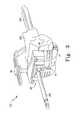
FIG. 1 shows an orthopaedicsurgical instrument 10 for use on a femur of a patient which includes a modularfemoral trial 12. The modularfemoral trial 12 includes a posteriorfemoral trial 14, an anteriorfemoral trial 16, and afemoral box trial 18. The posteriorfemoral trial 14, the anteriorfemoral trial 16, and thefemoral box trial 18 are configured to be removably coupled to each other as discussed in more detail below. Thetrials - The posterior
femoral trial 14 includes an articulatingsurface 20 configured to contact a natural or prosthetic upper bearing surface of the patient's tibia. The articulatingsurface 20 includes a pair ofcondylar surfaces opening 26 therebetween. The posteriorfemoral trial 14 also includes a number of cutting guides 28, which may be used during an orthopaedic surgical procedure to resect a portion of a patient's femur. For example, the posteriorfemoral trial 14 may include a number of distal cutting guides 30 and a number of posterior cutting guides 32. In this embodiment, the posteriorfemoral trial 14 includes three distal cutting guides 30 and three posterior cutting guides 32. The cutting guides 28 are embodied as elongated openings configured to receive a bone saw blade of an orthopaedic bone saw or other cutting device. The distal cutting guides 30 may be used by an orthopaedic surgeon to facilitate the resection of a portion of the distal end of a patient's femur. Similarly, the posterior cutting guides 32 may be used by the orthopaedic surgeon to facilitate the resection of a portion of the posterior condyles of the patient's femur. - Each of the cutting guides of the distal cutting guides 30 and the posterior cutting guides 32 are spaced apart from each respective cutting
guide 30, 32 a fixed distance. For example, the distal cutting guides 30 may be spaced apart from each other about 2 mm. Similarly, the posterior cutting guides 32 may be spaced apart from each other about 2 mm. As such, during the orthopaedic surgical procedure, the surgeon may select the particular cuttingguide femoral trial 14 may include any number of cutting guides 22, which may be spaced apart by an amount less or greater than 2 mm. - Similar to the posterior
femoral trial 14, the anteriorfemoral trial 16 includes an articulatingsurface 34 configured to contact a natural or prosthetic upper bearing surface of the patient's tibia and/or a natural or prosthetic surface of the patient's patella. The articulatingsurface 34 includes a pair ofcondylar surfaces 36, 38 spaced apart to form an opening 40 therebetween. The anteriorfemoral trial 16 also includes a number of cutting guides 42. The cutting guides 42 are embodied as distal cutting guides 44, but may be defined in the anterior femoral trial as other types of cutting guides in other embodiments. - The anterior
femoral trial 16 also includes a pair ofapertures 46 defined in the articulatingsurface 34 toward the anterior end of thetrial 16. Theapertures 32 are configured to receive posts or pegs of various orthopaedic surgical tools usable by an orthopaedic surgeon during an orthopaedic surgical procedure as discussed in more detail below. For example, a box cutguide 48 may be coupled to the anteriorfemoral trial 16 via theapertures 46. That is, the box cutguide 48 includes a cuttingguide platform 50 and a pair ofpegs 52, which extend downwardly from theplatform 50 as shown inFIG. 1 . Thepegs 52 are sized and positioned on theplatform 50 such that thepegs 52 are received in theapertures 46 of the anteriorfemoral trial 16 when thebox cutting guide 48 is coupled thereto as discussed in more detail below with reference to process step 110 ofalgorithm 100. - As discussed above, the posterior
femoral trial 14 and the anteriorfemoral trial 16 are configured to be coupled together. As such, the posteriorfemoral trial 14 includes a pair of end surfaces 54 that confront or abut a corresponding pair of end surfaces 56 of the anteriorfemoral trial 16. Thetrials trials trials openings 26, 40 of therespective rails FIG. 5 ) configured to receive a portion of thefemoral box trial 18 as discussed below. The posteriorfemoral trial 14 and the anteriorfemoral trial 16 include corresponding tracks orslots inner sidewalls trials tracks - After the
trials femoral box trial 18 may be coupled to thetrials femoral box trial 18 includes twoside walls sidewalls rail femoral box trial 18 may be coupled to the posterior andanterior trials femoral box 18 such that therails corresponding tracks FIG. 7 ) may be coupled to the femoral box trial using bolt or other securingdevice 82. - As discussed in more detail below, a
base block 82 may be coupled to the posteriorfemoral trial 14 in place of the anteriorfemoral trial 16 during the orthopaedic surgical procedure. Similar to the anteriorfemoral trial 16, thebase block 82 includes a pair ofends 84 configured to confront or abut theends 54 of the posteriorfemoral trial 14. Thebase block 82 and the posteriorfemoral trial 14 may be coupled together using any suitable securing devices such as pins, screws, bolts, or the like. Thebase block 82 is also configured to be secured to the patient's femur during the orthopaedic surgical procedure. As such, thebase block 82 includes a number of apertures for receiving guide pins therein to secure theblock 82 to the femur. - The
base block 82 forms an attachment base to which a number of different orthopaedic surgical tools or instruments may be coupled. For example, thebase block 82 includes arecess 86 configured to receive abushing 88. Thebushing 88 includes aframe 90 and abushing insert 92. Theframe 90 is configured to be received in therecess 86 of thebase block 82 and includes anaperture 94 configured to receive thebushing insert 92. Thebushing insert 92 is a intramedullary bushing configured to receive an intramedullary rod. However, in other embodiments thebushing insert 92 may be embodied as or replaced with a drill bushing. In addition to thebushing 88, astylus 96 may be coupled to thebase block 82. Thestylus 96 includes a number of pin guides 98, which are sized and position to match the pin guides of thebase block 82. - It should be appreciated that orthopaedic
surgical instrument 10 is a modular instrument that may be assembled in one of a number of configurations. For example, theinstrument 10 may be initially configured as a resectioning guide or tool. Over the course of an orthopaedic surgical procedure, theinstrument 10 may be configured as a femoral trial as discussed in more detail below. As such, an orthopaedic surgeon may perform resectioning of the patient's femur, trial reduction, and analyze the trial range of motion using theinstrument 10. - Referring now to
FIG. 2 , the orthopaedicsurgical instrument 10 may be used in an orthopaedicsurgical procedure 100 for preparing a patient's femur for an orthopaedic implant. It should be appreciated that thesurgical procedure 100 and theinstrument 10 are described herein in reference to an orthopaedic revision knee surgical procedure but may be used in a primary knee surgical procedure in other embodiments. - The
orthopaedic procedure 100 begins with aprocess step 102 in which the patient'sfemur 200 is initially prepared. For example, inprocess step 104 the medullary canal of the patient'sfemur 200 is prepared. To do so, the orthopaedic surgeon may drill and ream the medullary canal to define a cavity in the patient'sfemur 200. Once the cavity is sufficiently defined, the orthopaedic surgeon may insert anintramedullary rod 202 into the cavity defined in the medullary canal of the patient'sfemur 200. In some embodiments, therod 202 includes or is coupled to astem trial 204, which is inserted into the prepared medullary canal (for example, seeFIG. 3 ). - After the
intramedullary rod 202 is inserted into the patient'sfemur 200, theinstrument 100 may be secured and aligned to the patient'sfemur 200 inprocess step 108. To do so, the orthopaedic surgeon assembles theinstrument 10 in a configuration for alignment of theinstrument 10 inprocess step 110. For example, as shown inFIG. 3 , the orthopaedic surgeon couples the posteriorfemoral trial 14 to thebase block 82. Additionally, thebushing 88 is coupled to thebase block 82. In this embodiment, thebushing 88 includes abushing insert 92 configured for intramedullary rods, but in other embodiments or steps, thebushing insert 92 may be replaced with a drill bushing or the like. - After the
instrument 10 has been assembled into the alignment configuration, theinstrument 10 may be coupled to theintramedullary rod 202, which was inserted in the patient'sfemur 200 inprocess step 106. To do so, theintramedullary rod 202 is inserted into the intramedullaryrod bushing insert 92. Theinstrument 10 may then be moved down therod 202 to thefemur 200 in a position for alignment. It should be appreciated that because theinstrument 10 includes the posteriorfemoral trial 14, theinstrument 10 may also be used for flexion gap balancing in the alignment configuration shown inFIG. 3 . - In
process step 112, the orthopaedicsurgical instrument 10 is aligned with respect to theintramedullary rod 202 and the patient'sfemur 200. To do so, the position of theinstrument 10 is adjusted such that thestylus 96 indicates on or contacts the anterior cortex of the patient'sfemur 200 so that the sizing of the orthopaedic prosthesis may be accomplished. After theinstrument 10 has been properly aligned, theinstrument 10 may be secured to the patient'sfemur 200 in some embodiments. To do so, thebase block 82 may be secured to thefemur 200 using guide pins or the like. - After the
instrument 10 has been aligned, the orthopaedic surgeon may begin resecting the patient'sfemur 200. For example, the surgeon may perform an anterior resection inprocess step 114 using theinstrument 10. For example, inprocess step 116, the orthopaedic surgeon assembles theinstrument 10 for anterior resection. To do so, as shown inFIG. 4 , thebushing 88 and thestylus 96 are removed from thebase block 82. Thebase block 82 may then be used as a cutting guide block. That is, atop surface 206 of thebase block 82 may be used as a cutting guide. It should be appreciated that thetop surface 206 forms a non-captured or open cutting guide. - In
process step 118, the surgeon performs the anterior resection of the patient'sfemur 200. To do so, the surgeon uses thetop surface 206 to guide a bone sawblade 208 of an orthopaedic bone saw. The bone sawblade 208 is typically kept substantially flat on thesurface 206 to perform the anterior cut. As shown inFIG. 4 , the anterior cut removes an anterior portion of the patient'sfemur 200 to create a substantial planaranterior surface 208. In addition to the anterior resectioning of the patient's femur, the surgeon may perform any required broaching. That is, because thebushing 88 has been removed from thebase block 82, the distal end of thefemur 200 is accessible through thebase block 82. As such, the orthopaedic surgeon may perform additional drilling or reaming on the distal end of thefemur 200. - After the surgeon has performed the anterior resection of the patient's
femur 200, the surgeon may use theinstrument 10 to perform additional resectioning. For example, inprocess step 120, the orthopaedic surgeon uses theinstrument 10 for augment resectioning of the patient'sfemur 200. To do so, inprocess step 122, theinstrument 10 is assembled in a configuration for augment resectioning. That is, as shown inFIG. 5 , thebase block 82 is removed from the posteriorfemoral trial 14. The anteriorfemoral trial 16 is coupled to the posteriorfemoral trial 14 in place of thebase block 82. As discussed above, thetrials trials individual openings 26, 40 of eachtrial opening 60 as shown inFIG. 5 . - After the
instrument 10 has been assembled in its augment resectioning configuration, the surgeon may perform the augment resectioning inprocess step 124. To do so, as shown inFIG. 5 , the surgeon may use the cutting guides 28, 42 of thetrials femoral trial 14. Additionally or alternatively, the surgeon may insert the bone sawblade 208 into one of the distal cutting guides 44 of the anteriorfemoral trial 16. The surgeon may use theinstrument 10 to perform any amount of augment resectioning. In addition, because the anteriorfemoral trial 16 is being used, theinstrument 10 may be used for further balancing of the flexion and extension gaps. As such, it should be appreciated that theinstrument 10 may be used for balancing as well as resectioning of the patient'sfemur 200 and joint. - In addition to the augment cuts performed in
process step 120, theinstrument 10 may be used to perform a number of femoral box cuts inprocess 126. To do so, theinstrument 10 is assembled into a configuration for the femoral box cuts. That is, as shown inFIG. 6 , the box cutguide 48 is coupled to the anteriorfemoral trial 16. As discussed above with reference toFIG. 1 , the box cutguide 48 may be coupled to thetrial 16 by positioning theguide 48 such that thepegs 52 of theguide 48 are received in theapertures 46 defined in the articulatingsurface 34 of the anteriorfemoral trial 16. - After the box cut
guide 48 has been coupled to the anteriorfemoral trial 16, the orthopaedic surgeon may perform the femoral box cuts inprocess step 130. To do so, the surgeon uses the top surface 212 of the box cutguide 48 to guide the bone sawblade 208. Again, the bone sawblade 208 is typically kept substantially flat on the surface 212 to perform the box cut. The femoral box cut removes portions of the patient'sfemur 200 to define an area for the femoral box of the femoral orthopaedic prosthesis. - After the orthopaedic surgeon has resectioned the patient's femur as desired, the surgeon may use the
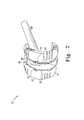
instrument 10 as a femoral trial to balance the patient's knee joint. To do so, theinstrument 10 is assembled in a femoral trial configuration as shown inFIG. 7 . That is, thefemoral box trial 18 is coupled to the anteriorfemoral trial 16 and the posteriorfemoral trial 14. As discussed above, thefemoral box trial 18 may be coupled to the posterior andanterior trials femoral box trial 18 such that therails femoral box trial 18 are received in thecorresponding tracks trials stem 80 may be secured to thefemoral box trial 18 using thebolt 82. It should be appreciated that thestem 80 is received in prepared intramedullary canal of the femur 200 (not shown for clarity of description). - After the
instrument 10 has been assembled for trials, the orthopaedic surgeon may analyze the patient's joint using theinstrument 10. For example, the surgeon may analyze the joint gap between the patient'sfemur 200 and tibia. Once satisfied with the preparation of the patient's femur, the orthopaedic surgeon may remove theinstrument 10 from thefemur 200 and implant the femoral prosthesis component.
Claims (9)
- A femoral orthopaedic surgical instrument (10) comprising:a posterior femoral trial (14),a base block (82) which can be removably coupled to the posterior femoral trial and which includes a plurality of apertures formed in it in which guide pins can be received to secure the base block to a patient's femur, an anterior femoral trial (16) including an anterior femoral trial cutting guide (44) defined therein,characterised inthat the posterior femoral trial includes a posterior femoral trial cutting guide (30, 32) defined therein, and in which the anterior femoral trial is configured to be coupled to the posterior femoral trial in place of the base block, andin that the instrument includes at least one of:(a) an intramedullary rod (202), and a bushing (88) which can be received in an opening in the base block, the bushing including an aperture in which the intramedullary rod can be received, and(b) a stylus (96) which can be coupled to the base block, for contacting the anterior cortex.
- The femoral orthopaedic surgical instrument of claim 1, in which the posterior femoral trial (14) includes a first cutting guide (32), a second cutting guide (32) spaced from the first cutting guide by a first distance, and a third cutting guide (32) spaced from the second cutting guide by the first distance.
- The femoral orthopaedic surgical instrument of claim 1, in which the posterior femoral trial (14) includes a distal cutting guide (30) and a posterior cutting guide (32).
- The femoral orthopaedic surgical instrument of claim 1, in which the bushing (88) comprises (i) a frame (90) received in the opening of the base block and (ii) a bushing insert (92) received in the frame, the bushing insert having an aperture defined therein configured to receive the intramedullary rod (202).
- The femoral orthopaedic surgical instrument of claim 1, which includes a box cutting guide (48) coupled to the anterior femoral trial (16), the box cutting guide comprising a platform (50), a first peg (52) extending from the platform, and a second peg (52) extending from the platform, in which the anterior femoral trial includes a first aperture (46) and a second aperture (46), the first peg being received in the first aperture and the second peg being received in the second aperture.
- The femoral orthopaedic surgical instrument of claim 1, which includes a femoral box trial (18) configured to be coupled to the anterior femoral trial (16) and the posterior femoral trial (14).
- The femoral orthopaedic surgical instrument of claim 6, in which:(i) the anterior femoral trial (16) includes a first slot (62) and second slot (64),(ii) the posterior femoral trial (14) includes a third slot (62) and fourth slot (64), and(iii) the femoral box trial (18) includes a first rail (76) and a second rail (76), the first rail being received in the first slot and the third slot and the second rail being received in the second slot and the fourth slot when the femoral box trial is coupled to the anterior femoral trial and the posterior femoral trial.
- The femoral orthopaedic surgical instrument of claim 6, in which the femoral anterior trial (16) and the femoral posterior trial (14) define an aperture between them when coupled together, and in which the femoral box trial (18) can be received in the aperture.
- The femoral orthopaedic surgical instrument of claim 6, which includes a stem (80) configured to be coupled to the femoral box trial (18).
Applications Claiming Priority (1)
| Application Number | Priority Date | Filing Date | Title |
|---|---|---|---|
| US11/865,022US8038681B2 (en) | 2007-09-30 | 2007-09-30 | Modular femoral orthopaedic surgical instrument |
Publications (3)
| Publication Number | Publication Date |
|---|---|
| EP2042111A2 EP2042111A2 (en) | 2009-04-01 |
| EP2042111A3 EP2042111A3 (en) | 2010-04-21 |
| EP2042111B1true EP2042111B1 (en) | 2015-10-28 |
Family
ID=40164173
Family Applications (1)
| Application Number | Title | Priority Date | Filing Date |
|---|---|---|---|
| EP08165421.2AActiveEP2042111B1 (en) | 2007-09-30 | 2008-09-29 | Modular Femoral Orthopaedic Surgical Instrument |
Country Status (2)
| Country | Link |
|---|---|
| US (1) | US8038681B2 (en) |
| EP (1) | EP2042111B1 (en) |
Families Citing this family (31)
| Publication number | Priority date | Publication date | Assignee | Title |
|---|---|---|---|---|
| CA2591977C (en)* | 2004-12-21 | 2013-07-30 | Smith & Nephew, Inc. | Distal femoral trial with removable cutting guide |
| US8771280B2 (en)* | 2010-03-08 | 2014-07-08 | Zimmer, Inc. | Femoral cut guide |
| USD649639S1 (en)* | 2010-05-28 | 2011-11-29 | Zimmer, Inc. | Combination modular femoral provisional prosthesis with cut guide |
| US9011453B2 (en)* | 2010-09-10 | 2015-04-21 | Zimmer, Inc. | Bone preserving intraoperative downsizing system for orthopaedic implants |
| CH704563B1 (en) | 2011-02-21 | 2015-04-30 | Microport Orthopedics Inc | Patient Specific Proberepositionsblock. |
| US8979847B2 (en) | 2011-06-06 | 2015-03-17 | Biomet Manufacturing, Llc | Method and apparatus for implanting a knee prosthesis |
| US9603604B2 (en) | 2011-10-28 | 2017-03-28 | Symmetry Medical Manufacturing, Inc. | Orthopaedic cutting block |
| US9050107B2 (en) | 2012-05-30 | 2015-06-09 | Depuy (Ireland) | Method of surgically preparing a patient's femur |
| US9468502B2 (en)* | 2012-08-31 | 2016-10-18 | Smith & Nephew, Inc. | Patient specific implant positioning |
| US20140207143A1 (en)* | 2013-01-24 | 2014-07-24 | Michael Lee | Allograft templates and methods of use |
| US9220511B2 (en)* | 2013-02-28 | 2015-12-29 | Depuy (Ireland) | Femoral orthopaedic surgical instrument including a measurement device and method of use of same |
| JP6152583B2 (en) | 2013-03-19 | 2017-06-28 | 京セラ株式会社 | Femoral component trial for knee joint |
| US10070868B2 (en) | 2013-08-02 | 2018-09-11 | Zimmer, Inc. | Resection shift guide and method |
| USD735328S1 (en)* | 2013-11-27 | 2015-07-28 | Depuy (Ireland) | Orthopaedic surgical instrument attachment device |
| GB201403020D0 (en)* | 2014-02-20 | 2014-04-09 | Depuy Ireland | Surgical instrument |
| US9795495B1 (en)* | 2014-08-23 | 2017-10-24 | Timothy Ray Miller | Instrumentation and methods for knee arthroplasty |
| CN109152580B (en) | 2016-05-18 | 2021-06-08 | 德普伊爱尔兰无限公司 | Orthopaedic instrument system for surgically preparing a femur of a patient |
| CA3024852A1 (en) | 2016-05-18 | 2017-11-23 | Depuy Ireland Unlimited Company | System and method for preparing a patient's femur in an orthopaedic joint replacement procedure |
| EP3730075B1 (en) | 2016-05-18 | 2022-07-27 | DePuy Ireland Unlimited Company | System for preparing a patient's tibia in an orthopaedic joint replacement procedure |
| US10709460B2 (en) | 2016-08-01 | 2020-07-14 | Howmedica Osteonics Corp. | Centering guide system for arthroplasty |
| US11039938B2 (en) | 2017-07-26 | 2021-06-22 | Optimotion Implants LLC | Modular knee prothesis |
| US11406502B2 (en) | 2017-03-02 | 2022-08-09 | Optimotion Implants LLC | Orthopedic implants and methods |
| US12083027B2 (en) | 2017-03-02 | 2024-09-10 | Optimotion Implants LLC | Universal femoral trial system and methods |
| US10537341B2 (en) | 2017-09-20 | 2020-01-21 | Depuy Ireland Unlimited Company | Orthopaedic system and method for assembling prosthetic components |
| US10543001B2 (en) | 2017-09-20 | 2020-01-28 | Depuy Ireland Unlimited Company | Method and instruments for assembling a femoral orthopaedic prosthesis |
| US10537446B2 (en) | 2017-09-20 | 2020-01-21 | Depuy Ireland Unlimited Company | Method and instruments for assembling an orthopaedic prosthesis |
| FR3083073B1 (en)* | 2018-06-29 | 2021-07-09 | Amplitude | FEMORAL PREPARATION ANCILLARY |
| JP7189758B2 (en)* | 2018-12-25 | 2022-12-14 | 京セラ株式会社 | Surgical instruments and surgical instrument systems |
| US11992422B2 (en)* | 2019-04-30 | 2024-05-28 | MAP Medical Solutions, LLC | Joint revision surgery apparatus |
| GB201913436D0 (en) | 2019-09-18 | 2019-10-30 | Depuy Ireland Ultd Co | Cutting block |
| US20220313282A1 (en)* | 2021-03-30 | 2022-10-06 | MAP Medical Solutions, LLC | Joint revision surgery apparatus |
Family Cites Families (16)
| Publication number | Priority date | Publication date | Assignee | Title |
|---|---|---|---|---|
| US5258032A (en) | 1992-04-03 | 1993-11-02 | Bertin Kim C | Knee prosthesis provisional apparatus and resection guide and method of use in knee replacement surgery |
| US5624444A (en)* | 1995-02-10 | 1997-04-29 | Wixon; Richard | Femoral resection instrumentation including three-dimensional jig and method of use |
| US5702460A (en) | 1995-02-15 | 1997-12-30 | Smith & Nephew, Inc. | Revision femoral trial prosthesis |
| US5683397A (en)* | 1995-02-15 | 1997-11-04 | Smith & Nephew, Inc. | Distal femoral cutting guide apparatus for use in knee joint replacement surgery |
| US5716361A (en) | 1995-11-02 | 1998-02-10 | Masini; Michael A. | Bone cutting guides for use in the implantation of prosthetic joint components |
| US5683472A (en)* | 1995-12-29 | 1997-11-04 | Johnson & Johnson Professional, Inc. | Femoral stem attachment for a modular knee prosthesis |
| AU737097B2 (en) | 1997-01-28 | 2001-08-09 | New York Society For The Relief Of The Ruptured And Crippled, Maintaining The Hospital For Special Surgery | Method and apparatus for femoral resection |
| US5879393A (en) | 1997-05-21 | 1999-03-09 | Smith & Nephew, Inc. | Trial femoral prosthesis for use in knee joint replacement surgery |
| US6488687B1 (en) | 1997-09-18 | 2002-12-03 | Medidea, Llc | Joint replacement method and apparatus |
| FR2770393B1 (en) | 1997-10-31 | 1999-12-31 | Protek Sa | FEMORAL CUTTING DEVICE FOR PLACING A TOTAL RECOVERY KNEE PROSTHESIS |
| US6080196A (en) | 1999-03-04 | 2000-06-27 | Bertin; Kim C. | Patella height gauge and method of locating a patella using same |
| US6827739B2 (en) | 2002-08-26 | 2004-12-07 | Zimmer Technology, Inc. | Easily assembled provisional orthopaedic implant |
| US20040102852A1 (en)* | 2002-11-22 | 2004-05-27 | Johnson Erin M. | Modular knee prosthesis |
| US20040153087A1 (en) | 2003-02-04 | 2004-08-05 | Sanford Adam H. | Provisional orthopedic implant with removable guide |
| FR2867056B1 (en) | 2004-03-02 | 2006-07-07 | Herve Arnould | DEVICE FOR COUPLE BETWEEN TIBIA AND FEMUR FOR THE PLACEMENT OF A PROSTHESIS |
| US20060200162A1 (en) | 2005-02-21 | 2006-09-07 | Zimmer Technology, Inc. | Total knee arthroplasty instruments |
- 2007
- 2007-09-30USUS11/865,022patent/US8038681B2/ennot_activeExpired - Fee Related
- 2008
- 2008-09-29EPEP08165421.2Apatent/EP2042111B1/enactiveActive
Also Published As
| Publication number | Publication date |
|---|---|
| EP2042111A2 (en) | 2009-04-01 |
| EP2042111A3 (en) | 2010-04-21 |
| US20090088762A1 (en) | 2009-04-02 |
| US8038681B2 (en) | 2011-10-18 |
Similar Documents
| Publication | Publication Date | Title |
|---|---|---|
| EP2042111B1 (en) | Modular Femoral Orthopaedic Surgical Instrument | |
| US8430932B2 (en) | Femoral prosthetic implant | |
| US6197064B1 (en) | Prosthetic implant | |
| AU689033B2 (en) | Tibial trial knee prosthesis and bone preparation system | |
| CA2469555C (en) | Apparatus and method for sculpting the surface of a bone joint | |
| EP1862149B1 (en) | Prosthesis and implementation system | |
| US8273131B2 (en) | Method and apparatus for positioning a multiple piece prosthesis | |
| US6056754A (en) | Method and apparatus for patella resection and guide handle | |
| AU2016289953B2 (en) | Femoral finishing guide | |
| US20040153087A1 (en) | Provisional orthopedic implant with removable guide | |
| JPH01250250A (en) | Apparatus used in knee prosthesis method | |
| JP2019516489A (en) | System and method for preparing a patient's femur in an orthopedic joint replacement procedure | |
| EP2777635B1 (en) | Surgical instrument | |
| EP2712589B1 (en) | Surgical instrument | |
| EP3760167A1 (en) | Femoral trial components and associated orthopaedic surgical method of use | |
| EP2774553A1 (en) | Femoral cutting instrument | |
| US20220354508A1 (en) | Cutting block | |
| US20230346394A1 (en) | Combination femoral preparation cutting blocks for knee arthroplasty |
Legal Events
| Date | Code | Title | Description |
|---|---|---|---|
| PUAI | Public reference made under article 153(3) epc to a published international application that has entered the european phase | Free format text:ORIGINAL CODE: 0009012 | |
| AK | Designated contracting states | Kind code of ref document:A2 Designated state(s):AT BE BG CH CY CZ DE DK EE ES FI FR GB GR HR HU IE IS IT LI LT LU LV MC MT NL NO PL PT RO SE SI SK TR | |
| AX | Request for extension of the european patent | Extension state:AL BA MK RS | |
| PUAL | Search report despatched | Free format text:ORIGINAL CODE: 0009013 | |
| AK | Designated contracting states | Kind code of ref document:A3 Designated state(s):AT BE BG CH CY CZ DE DK EE ES FI FR GB GR HR HU IE IS IT LI LT LU LV MC MT NL NO PL PT RO SE SI SK TR | |
| AX | Request for extension of the european patent | Extension state:AL BA MK RS | |
| RIC1 | Information provided on ipc code assigned before grant | Ipc:A61B 17/72 20060101ALN20100316BHEP Ipc:A61F 2/30 20060101ALN20100316BHEP Ipc:A61B 17/17 20060101ALI20100316BHEP Ipc:A61F 2/00 20060101ALN20100316BHEP Ipc:A61F 2/46 20060101ALI20100316BHEP Ipc:A61B 17/15 20060101AFI20090113BHEP | |
| 17P | Request for examination filed | Effective date:20100928 | |
| 17Q | First examination report despatched | Effective date:20101022 | |
| AKX | Designation fees paid | Designated state(s):AT BE BG CH CY CZ DE DK EE ES FI FR GB GR HR HU IE IS IT LI LT LU LV MC MT NL NO PL PT RO SE SI SK TR | |
| RAP1 | Party data changed (applicant data changed or rights of an application transferred) | Owner name:DEPUY (IRELAND) | |
| GRAP | Despatch of communication of intention to grant a patent | Free format text:ORIGINAL CODE: EPIDOSNIGR1 | |
| RIC1 | Information provided on ipc code assigned before grant | Ipc:A61B 17/72 20060101ALN20150422BHEP Ipc:A61F 2/30 20060101ALN20150422BHEP Ipc:A61F 2/46 20060101ALI20150422BHEP Ipc:A61B 17/15 20060101AFI20150422BHEP Ipc:A61B 17/17 20060101ALI20150422BHEP Ipc:A61F 2/00 20060101ALN20150422BHEP | |
| INTG | Intention to grant announced | Effective date:20150522 | |
| GRAS | Grant fee paid | Free format text:ORIGINAL CODE: EPIDOSNIGR3 | |
| GRAA | (expected) grant | Free format text:ORIGINAL CODE: 0009210 | |
| AK | Designated contracting states | Kind code of ref document:B1 Designated state(s):AT BE BG CH CY CZ DE DK EE ES FI FR GB GR HR HU IE IS IT LI LT LU LV MC MT NL NO PL PT RO SE SI SK TR | |
| REG | Reference to a national code | Ref country code:GB Ref legal event code:FG4D | |
| REG | Reference to a national code | Ref country code:CH Ref legal event code:EP | |
| REG | Reference to a national code | Ref country code:AT Ref legal event code:REF Ref document number:757482 Country of ref document:AT Kind code of ref document:T Effective date:20151115 | |
| REG | Reference to a national code | Ref country code:IE Ref legal event code:FG4D | |
| REG | Reference to a national code | Ref country code:CH Ref legal event code:NV Representative=s name:E. BLUM AND CO. AG PATENT- UND MARKENANWAELTE , CH | |
| REG | Reference to a national code | Ref country code:DE Ref legal event code:R096 Ref document number:602008040863 Country of ref document:DE | |
| REG | Reference to a national code | Ref country code:LT Ref legal event code:MG4D | |
| REG | Reference to a national code | Ref country code:NL Ref legal event code:MP Effective date:20151028 | |
| REG | Reference to a national code | Ref country code:AT Ref legal event code:MK05 Ref document number:757482 Country of ref document:AT Kind code of ref document:T Effective date:20151028 | |
| PG25 | Lapsed in a contracting state [announced via postgrant information from national office to epo] | Ref country code:IS Free format text:LAPSE BECAUSE OF FAILURE TO SUBMIT A TRANSLATION OF THE DESCRIPTION OR TO PAY THE FEE WITHIN THE PRESCRIBED TIME-LIMIT Effective date:20160228 Ref country code:ES Free format text:LAPSE BECAUSE OF FAILURE TO SUBMIT A TRANSLATION OF THE DESCRIPTION OR TO PAY THE FEE WITHIN THE PRESCRIBED TIME-LIMIT Effective date:20151028 Ref country code:HR Free format text:LAPSE BECAUSE OF FAILURE TO SUBMIT A TRANSLATION OF THE DESCRIPTION OR TO PAY THE FEE WITHIN THE PRESCRIBED TIME-LIMIT Effective date:20151028 Ref country code:NL Free format text:LAPSE BECAUSE OF FAILURE TO SUBMIT A TRANSLATION OF THE DESCRIPTION OR TO PAY THE FEE WITHIN THE PRESCRIBED TIME-LIMIT Effective date:20151028 Ref country code:NO Free format text:LAPSE BECAUSE OF FAILURE TO SUBMIT A TRANSLATION OF THE DESCRIPTION OR TO PAY THE FEE WITHIN THE PRESCRIBED TIME-LIMIT Effective date:20160128 Ref country code:LT Free format text:LAPSE BECAUSE OF FAILURE TO SUBMIT A TRANSLATION OF THE DESCRIPTION OR TO PAY THE FEE WITHIN THE PRESCRIBED TIME-LIMIT Effective date:20151028 Ref country code:IT Free format text:LAPSE BECAUSE OF FAILURE TO SUBMIT A TRANSLATION OF THE DESCRIPTION OR TO PAY THE FEE WITHIN THE PRESCRIBED TIME-LIMIT Effective date:20151028 | |
| PG25 | Lapsed in a contracting state [announced via postgrant information from national office to epo] | Ref country code:PL Free format text:LAPSE BECAUSE OF FAILURE TO SUBMIT A TRANSLATION OF THE DESCRIPTION OR TO PAY THE FEE WITHIN THE PRESCRIBED TIME-LIMIT Effective date:20151028 Ref country code:SE Free format text:LAPSE BECAUSE OF FAILURE TO SUBMIT A TRANSLATION OF THE DESCRIPTION OR TO PAY THE FEE WITHIN THE PRESCRIBED TIME-LIMIT Effective date:20151028 Ref country code:FI Free format text:LAPSE BECAUSE OF FAILURE TO SUBMIT A TRANSLATION OF THE DESCRIPTION OR TO PAY THE FEE WITHIN THE PRESCRIBED TIME-LIMIT Effective date:20151028 Ref country code:AT Free format text:LAPSE BECAUSE OF FAILURE TO SUBMIT A TRANSLATION OF THE DESCRIPTION OR TO PAY THE FEE WITHIN THE PRESCRIBED TIME-LIMIT Effective date:20151028 Ref country code:LV Free format text:LAPSE BECAUSE OF FAILURE TO SUBMIT A TRANSLATION OF THE DESCRIPTION OR TO PAY THE FEE WITHIN THE PRESCRIBED TIME-LIMIT Effective date:20151028 Ref country code:PT Free format text:LAPSE BECAUSE OF FAILURE TO SUBMIT A TRANSLATION OF THE DESCRIPTION OR TO PAY THE FEE WITHIN THE PRESCRIBED TIME-LIMIT Effective date:20160229 Ref country code:GR Free format text:LAPSE BECAUSE OF FAILURE TO SUBMIT A TRANSLATION OF THE DESCRIPTION OR TO PAY THE FEE WITHIN THE PRESCRIBED TIME-LIMIT Effective date:20160129 | |
| PG25 | Lapsed in a contracting state [announced via postgrant information from national office to epo] | Ref country code:CZ Free format text:LAPSE BECAUSE OF FAILURE TO SUBMIT A TRANSLATION OF THE DESCRIPTION OR TO PAY THE FEE WITHIN THE PRESCRIBED TIME-LIMIT Effective date:20151028 | |
| REG | Reference to a national code | Ref country code:DE Ref legal event code:R097 Ref document number:602008040863 Country of ref document:DE | |
| REG | Reference to a national code | Ref country code:FR Ref legal event code:PLFP Year of fee payment:9 | |
| PG25 | Lapsed in a contracting state [announced via postgrant information from national office to epo] | Ref country code:RO Free format text:LAPSE BECAUSE OF FAILURE TO SUBMIT A TRANSLATION OF THE DESCRIPTION OR TO PAY THE FEE WITHIN THE PRESCRIBED TIME-LIMIT Effective date:20151028 Ref country code:SK Free format text:LAPSE BECAUSE OF FAILURE TO SUBMIT A TRANSLATION OF THE DESCRIPTION OR TO PAY THE FEE WITHIN THE PRESCRIBED TIME-LIMIT Effective date:20151028 Ref country code:DK Free format text:LAPSE BECAUSE OF FAILURE TO SUBMIT A TRANSLATION OF THE DESCRIPTION OR TO PAY THE FEE WITHIN THE PRESCRIBED TIME-LIMIT Effective date:20151028 Ref country code:EE Free format text:LAPSE BECAUSE OF FAILURE TO SUBMIT A TRANSLATION OF THE DESCRIPTION OR TO PAY THE FEE WITHIN THE PRESCRIBED TIME-LIMIT Effective date:20151028 | |
| PLBE | No opposition filed within time limit | Free format text:ORIGINAL CODE: 0009261 | |
| STAA | Information on the status of an ep patent application or granted ep patent | Free format text:STATUS: NO OPPOSITION FILED WITHIN TIME LIMIT | |
| 26N | No opposition filed | Effective date:20160729 | |
| PG25 | Lapsed in a contracting state [announced via postgrant information from national office to epo] | Ref country code:SI Free format text:LAPSE BECAUSE OF FAILURE TO SUBMIT A TRANSLATION OF THE DESCRIPTION OR TO PAY THE FEE WITHIN THE PRESCRIBED TIME-LIMIT Effective date:20151028 | |
| PG25 | Lapsed in a contracting state [announced via postgrant information from national office to epo] | Ref country code:BE Free format text:LAPSE BECAUSE OF FAILURE TO SUBMIT A TRANSLATION OF THE DESCRIPTION OR TO PAY THE FEE WITHIN THE PRESCRIBED TIME-LIMIT Effective date:20151028 | |
| PG25 | Lapsed in a contracting state [announced via postgrant information from national office to epo] | Ref country code:MC Free format text:LAPSE BECAUSE OF FAILURE TO SUBMIT A TRANSLATION OF THE DESCRIPTION OR TO PAY THE FEE WITHIN THE PRESCRIBED TIME-LIMIT Effective date:20151028 | |
| REG | Reference to a national code | Ref country code:FR Ref legal event code:PLFP Year of fee payment:10 | |
| PG25 | Lapsed in a contracting state [announced via postgrant information from national office to epo] | Ref country code:LU Free format text:LAPSE BECAUSE OF NON-PAYMENT OF DUE FEES Effective date:20160929 | |
| PG25 | Lapsed in a contracting state [announced via postgrant information from national office to epo] | Ref country code:HU Free format text:LAPSE BECAUSE OF FAILURE TO SUBMIT A TRANSLATION OF THE DESCRIPTION OR TO PAY THE FEE WITHIN THE PRESCRIBED TIME-LIMIT; INVALID AB INITIO Effective date:20080929 Ref country code:CY Free format text:LAPSE BECAUSE OF FAILURE TO SUBMIT A TRANSLATION OF THE DESCRIPTION OR TO PAY THE FEE WITHIN THE PRESCRIBED TIME-LIMIT Effective date:20151028 | |
| PG25 | Lapsed in a contracting state [announced via postgrant information from national office to epo] | Ref country code:TR Free format text:LAPSE BECAUSE OF FAILURE TO SUBMIT A TRANSLATION OF THE DESCRIPTION OR TO PAY THE FEE WITHIN THE PRESCRIBED TIME-LIMIT Effective date:20151028 Ref country code:MT Free format text:LAPSE BECAUSE OF NON-PAYMENT OF DUE FEES Effective date:20160930 | |
| PG25 | Lapsed in a contracting state [announced via postgrant information from national office to epo] | Ref country code:BG Free format text:LAPSE BECAUSE OF FAILURE TO SUBMIT A TRANSLATION OF THE DESCRIPTION OR TO PAY THE FEE WITHIN THE PRESCRIBED TIME-LIMIT Effective date:20151028 | |
| REG | Reference to a national code | Ref country code:FR Ref legal event code:PLFP Year of fee payment:11 | |
| PGFP | Annual fee paid to national office [announced via postgrant information from national office to epo] | Ref country code:FR Payment date:20220808 Year of fee payment:15 | |
| PG25 | Lapsed in a contracting state [announced via postgrant information from national office to epo] | Ref country code:FR Free format text:LAPSE BECAUSE OF NON-PAYMENT OF DUE FEES Effective date:20230930 | |
| PGFP | Annual fee paid to national office [announced via postgrant information from national office to epo] | Ref country code:DE Payment date:20240806 Year of fee payment:17 Ref country code:IE Payment date:20240812 Year of fee payment:17 | |
| PGFP | Annual fee paid to national office [announced via postgrant information from national office to epo] | Ref country code:GB Payment date:20240808 Year of fee payment:17 | |
| PGFP | Annual fee paid to national office [announced via postgrant information from national office to epo] | Ref country code:CH Payment date:20241001 Year of fee payment:17 |