EP2042106B1 - Staple drive assembly - Google Patents
Staple drive assemblyDownload PDFInfo
- Publication number
- EP2042106B1 EP2042106B1EP08252860AEP08252860AEP2042106B1EP 2042106 B1EP2042106 B1EP 2042106B1EP 08252860 AEP08252860 AEP 08252860AEP 08252860 AEP08252860 AEP 08252860AEP 2042106 B1EP2042106 B1EP 2042106B1
- Authority
- EP
- European Patent Office
- Prior art keywords
- staple
- pusher
- cam
- drive
- actuation sled
- Prior art date
- Legal status (The legal status is an assumption and is not a legal conclusion. Google has not performed a legal analysis and makes no representation as to the accuracy of the status listed.)
- Not-in-force
Links
Images


Classifications
- A—HUMAN NECESSITIES
- A61—MEDICAL OR VETERINARY SCIENCE; HYGIENE
- A61B—DIAGNOSIS; SURGERY; IDENTIFICATION
- A61B17/00—Surgical instruments, devices or methods
- A61B17/10—Surgical instruments, devices or methods for applying or removing wound clamps, e.g. containing only one clamp or staple; Wound clamp magazines
- A61B17/105—Wound clamp magazines
- A—HUMAN NECESSITIES
- A61—MEDICAL OR VETERINARY SCIENCE; HYGIENE
- A61B—DIAGNOSIS; SURGERY; IDENTIFICATION
- A61B17/00—Surgical instruments, devices or methods
- A61B17/068—Surgical staplers, e.g. containing multiple staples or clamps
- A61B17/072—Surgical staplers, e.g. containing multiple staples or clamps for applying a row of staples in a single action, e.g. the staples being applied simultaneously
- A61B17/07207—Surgical staplers, e.g. containing multiple staples or clamps for applying a row of staples in a single action, e.g. the staples being applied simultaneously the staples being applied sequentially
- A—HUMAN NECESSITIES
- A61—MEDICAL OR VETERINARY SCIENCE; HYGIENE
- A61B—DIAGNOSIS; SURGERY; IDENTIFICATION
- A61B17/00—Surgical instruments, devices or methods
- A61B17/068—Surgical staplers, e.g. containing multiple staples or clamps
- A—HUMAN NECESSITIES
- A61—MEDICAL OR VETERINARY SCIENCE; HYGIENE
- A61B—DIAGNOSIS; SURGERY; IDENTIFICATION
- A61B17/00—Surgical instruments, devices or methods
- A61B17/068—Surgical staplers, e.g. containing multiple staples or clamps
- A61B17/0682—Surgical staplers, e.g. containing multiple staples or clamps for applying U-shaped staples or clamps, e.g. without a forming anvil
- A—HUMAN NECESSITIES
- A61—MEDICAL OR VETERINARY SCIENCE; HYGIENE
- A61B—DIAGNOSIS; SURGERY; IDENTIFICATION
- A61B17/00—Surgical instruments, devices or methods
- A61B17/068—Surgical staplers, e.g. containing multiple staples or clamps
- A61B17/072—Surgical staplers, e.g. containing multiple staples or clamps for applying a row of staples in a single action, e.g. the staples being applied simultaneously
- A—HUMAN NECESSITIES
- A61—MEDICAL OR VETERINARY SCIENCE; HYGIENE
- A61B—DIAGNOSIS; SURGERY; IDENTIFICATION
- A61B17/00—Surgical instruments, devices or methods
- A61B17/064—Surgical staples, i.e. penetrating the tissue
- A61B17/0644—Surgical staples, i.e. penetrating the tissue penetrating the tissue, deformable to closed position
- A—HUMAN NECESSITIES
- A61—MEDICAL OR VETERINARY SCIENCE; HYGIENE
- A61B—DIAGNOSIS; SURGERY; IDENTIFICATION
- A61B17/00—Surgical instruments, devices or methods
- A61B17/068—Surgical staplers, e.g. containing multiple staples or clamps
- A61B2017/0688—Packages or dispensers for surgical staplers
- A—HUMAN NECESSITIES
- A61—MEDICAL OR VETERINARY SCIENCE; HYGIENE
- A61B—DIAGNOSIS; SURGERY; IDENTIFICATION
- A61B17/00—Surgical instruments, devices or methods
- A61B17/068—Surgical staplers, e.g. containing multiple staples or clamps
- A61B17/072—Surgical staplers, e.g. containing multiple staples or clamps for applying a row of staples in a single action, e.g. the staples being applied simultaneously
- A61B2017/07214—Stapler heads
- A61B2017/07235—Stapler heads containing different staples, e.g. staples of different shapes, sizes or materials
- A—HUMAN NECESSITIES
- A61—MEDICAL OR VETERINARY SCIENCE; HYGIENE
- A61B—DIAGNOSIS; SURGERY; IDENTIFICATION
- A61B17/00—Surgical instruments, devices or methods
- A61B17/068—Surgical staplers, e.g. containing multiple staples or clamps
- A61B17/072—Surgical staplers, e.g. containing multiple staples or clamps for applying a row of staples in a single action, e.g. the staples being applied simultaneously
- A61B2017/07214—Stapler heads
- A61B2017/07242—Stapler heads achieving different staple heights during the same shot, e.g. using an anvil anvil having different heights or staples of different sizes
- A—HUMAN NECESSITIES
- A61—MEDICAL OR VETERINARY SCIENCE; HYGIENE
- A61B—DIAGNOSIS; SURGERY; IDENTIFICATION
- A61B17/00—Surgical instruments, devices or methods
- A61B17/068—Surgical staplers, e.g. containing multiple staples or clamps
- A61B17/072—Surgical staplers, e.g. containing multiple staples or clamps for applying a row of staples in a single action, e.g. the staples being applied simultaneously
- A61B2017/07214—Stapler heads
- A61B2017/07278—Stapler heads characterised by its sled or its staple holder
Definitions
- the present disclosurerelates to stapling apparatus. More particularly, the present disclosure relates to a staple drive assembly for use in a staple cartridge of a stapling apparatus.
- Surgical stapling apparatusare widely used in surgical procedures to fasten body tissue quickly and efficiently by driving fasteners, or staples into the tissue.
- a drive membermoves transversely to the direction the staples are to be driven.
- such stapling apparatusemploy a number of staple pusher elements located in grooved slots of a staple cartridge and arranged end to end in rows.
- the transversely moving drive membercontacts a cam member on the staple pusher thereby pushing the staple pusher vertically in the grooved slot.
- the staple pushertransmits linear motion from the drive member to the staples.
- the rows of staplesare thereby driven into the body tissue to be fastened.
- staple pushers for driving one or more surgical staplesmay offer more resistance to longitudinal movement of the drive member. It is desirable that the staple pusher permit application of a relatively smooth ejection force throughout the operation of the drive member. It is also desirable that the stapling apparatus form a plurality of finished staples having a substantially uniform configuration.
- US 5,871,135discloses a surgical stapler comprising at least one cam having a cam surface, an arrangement for actuating the cam for a longitudinal firing movement of the cam surface, a cartridge having a plurality of staple drive members driven by the longitudinal movement of the cam surface, and a plurality of surgical staples respectively associated with the staple drive members for being fired by the longitudinal movement of the cam surface.
- the staple drive membersinclude a pair of alternating first and second staple drive members, the first staple drive member including a laterally spaced pair of staple driving surfaces, the second staple drive member including a single staple driving surface.
- US 6,010,054discloses a linear stapling instrument for use in surgical procedures including, inter alia, a staple housing.
- the housingincludes a plurality of staple drivers.
- the staple drivershave an upper surface bearing on a staple and a lower camming surface.
- the staple driversare slidably mounted in the housing for movement from an initial lower position to an upper position.
- the housingalso includes a sled slidably mounted in the housing for movement from an unfired position to a fired position.
- US 2007/194079discloses a surgical stapling device comprising an end effector.
- the end effectoralso comprises a plurality of staple drivers moveable supported within the staple cartridge.
- a first quantity of the staple drivershave a first height and a second quantity of the staple drivers have a second height, wherein the first height is less than the second height such that the staples driven by the first quantity of staple drivers have a longer formed length than the staples driven by the second quantity of staple drivers.
- EP 1 772 105discloses a staple drive assembly including an actuation sled and at least one staple pusher.
- the staple drive assemblyis adapted to fit within a staple cartridge having a plurality of staples and a corresponding number of retention slots.
- the at least one staple pusherincludes at least one pusher plate (166) for releasably engaging a backspan of a staple.
- WO 02/30297discloses a surgical fastener applying apparatus including a cartridge half-section and an anvil half-section with the cartridge and anvil half-sections being relatively movable from an unclamped position to a fully clamped position.
- the apparatusincludes a replaceable staple cartridge assembly having a plurality of surgical staples and a pivotably mounted safety lock-out.
- the present disclosureis directed towards a staple drive assembly for use in a staple cartridge.
- the staple drive assemblyincludes an actuation sled and at least one staple pusher.
- the staple cartridgeincludes a tissue contacting surface having a number of retention slots wherein each retention slot is adapted for releasably receiving a staple.
- the staple cartridgemay include a guide channel extending from a proximal portion to a distal portion along its longitudinal axis.
- the staple cartridgeis adapted for use in a surgical stapler having a drive mechanism.
- the actuation sledincludes a base, at least one camming member and a guide member.
- Each camming memberincludes a first or leading cam wedge and a second or trailing cam wedge.
- the leading and trailing cam wedgesare laterally and longitudinally spaced apart from one another. Spacing of the cam wedges apart, both laterally and longitudinally, creates a situation in which the staple pusher is contacted at points offset in two planes so that as the staple pusher is driven, it is controlled and driven substantially perpendicular to the tissue plane of the cartridge without rocking in any direction which would compromise driving the staple perpendicular to the tissue contacting plane.
- each cam wedgeincludes a first drive face and a second drive face.
- first drive facesform first drive angles with respect to the base and second drive faces form second drive angles with respect to a plane that is substantially parallel to the base.
- the guide memberis adapted for slidably engaging the guide channel for aligning and guiding the actuation sled as it translates through the staple cartridge.
- first drive facesare oriented such that first drive angles may be in a range of about 30° to about 40° while the second drive faces are oriented such that second drive angles may be in a range of about 15° to about 25°.
- Each staple pusherincludes at least one pusher plate and at least one cam member.
- each staple pusherincludes three pusher plates and two cam members.
- each staple pusherincludes one pusher plate and two cam members.
- each staple pusherincludes two pusher plates and two cam members.
- First and second cam membersare adapted for slidably engaging one of the cam assemblies of the actuation sled.
- Each cam memberincludes first and second cam surfaces that define respective first and second engagement or receiving angles that are complementary to the first and second drive angles.
- the first receiving anglesmay be in a range of about 15° to about 55° while the second receiving angles may be in a range of about 5° to about 35°.
- first receiving anglesmay be in a range of about 25° to about 45° while the second receiving angles may be in a range of about 10° to about 30°. In a further embodiment, the first receiving angle may be in the range of about 30° to about 40° while the second receiving angle may be in the range of about 15° to about 25°.
- the first and second cam membersare longitudinally and laterally spaced apart to complement the arrangement of the leading and trailing cam wedges of the actuation sled.
- Distal travel of the actuation sled through the staple cartridgecauses the sequential engagement of the actuation sled and the staple pushers disposed in the staple cartridge.
- the first drivefaces slidably engage the first cam surfaces thereby urging each staple pusher in a generally vertical direction.
- Each camming membercontacts each staple pusher in at least two longitudinally spaced locations for urging each staple pusher vertically.
- This longitudinally staggered arrangement of the drive faces in cooperation with the complementary staggered arrangement of the cam membersmaximizes the longitudinal stability of the staple pusher as it moves vertically. Additionally, the first and second drive angles in cooperation with the complementary first and second receiving angles contribute to the improved longitudinal stability of each staple pusher.
- an actuation sledincludes substantially the same or similar components, but the first and second drive angles may be in a range of about 5° to about 35° while the second drive angles may be in a range of about 20° to about 55°. In another embodiment, first drive angles may be in a range of about 10° to about 30° while second drive angles may be in a range of about 25° to about 45°. In a further embodiment, first drive angles may be in a range of about 15° to about 25° while second drive angles may be in a range of about 30° to about 40°.
- the first drive facesslidably engage the second cam surfaces urging each staple pusher in a generally vertical direction.
- the second drive facesengage first cam surfaces as the first drive faces disengage from the second cam surfaces.
- Applicantshave found that providing a cam wedges with a first drive surface angle which is less than the second drive angle provides a smooth firing stroke. Similar to the previous embodiment, longitudinal stability of the staple pusher is maximized by the longitudinally staggered (i.e. spaced apart) cam members in cooperation with the complementarily staggered cam wedges.
- the staple pushercontacts both drive surfaces as contact with the staple pusher transitions from contacting one drive surface to the other drive surface.
- an actuation sledthat includes the same or substantially similar components.
- the actuation sledincludes first and second camming members, a base, and a guide member.
- Each camming memberfurther includes first and second cam wedges that are longitudinally spaced apart and define a drive angle with respect to the base. The first and second cam wedges of each camming member are laterally spaced apart as well.
- the actuation sledincludes first and second camming members, a base, and a guide member.
- Each camming memberfurther includes first and second cam wedges that are laterally spaced apart from each other and define a plurality of drive angles with respect to the base.
- each cam wedgedefines a first set of drive angles that may be in the range of about 15° to about 25° and a second set of drive angles that may be in the range of about 26° to about 36°.
- each cam wedgedefines a first set of drive angles that may be in the range of about 17° to about 23° and a second set of drive angles that may be in the range of about 28° to about 34°. In a further embodiment, each cam wedge defines a first set of drive angles that may be in the range of about 19° to about 21° and a second set of drive angles that may be in the range of about 30° to about 32°.
- an actuation sledhaving the same or substantially similar components.
- the actuation sledincludes first and second camming members, a base, and a guide member.
- Each camming memberfurther includes first and second cam wedges that are laterally and longitudinally spaced apart from each other and define a plurality of drive angles with respect to the base.
- each cam wedgedefines a first set of drive angles that may be in the range of about 15° to about 55° and a second set of drive angles that may be in the range of about 5° to about 35°.
- each cam wedgedefines a first set of drive angles that may be in the range of about 25° to about 45° and a second set of drive angles that may be in the range of about 10° to about 30°. In a further embodiment, each cam wedge defines a first set of drive angles that may be in the range of about 30° to about 40° and a second set of drive angles that may be in the range of about 10° to about 30°.
- each of the described actuation sledsmay be included at a distal end of a cam bar or actuation member in a surgical stapling apparatus.
- the staple drive assemblymay include at least one proximal staple pusher, at least one middle staple pusher and at least one distal staple pusher.
- Proximal staple pusheris disposed at the proximal end of the staple cartridge and is adapted to eject the outermost, most proximal staple.
- Distal staple pusheris positioned on the distal end of staple cartridge and is configured to eject the outermost, most distal staples.
- Each staple pusherhas first and second cam members. In turn, each cam member has at least one engagement surface.
- the proximal staple pusherhas a single pusher plate
- the middle staple pusherhas three pusher plates
- the distal staple pusherhas four pusher plates.
- controlled driving of the staple pusherscan be maximized by providing cam wedges which are offset both laterally and longitudinally from each other with each drive surface having a first drive angle which is less than the second drive angle.
- distalrefers to that portion of the instrument, or component thereof which is further from the user while the term “proximal” refers to that portion of the instrument or component thereof which is closer to the user.
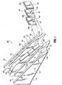
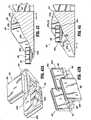
- Staple drive assembly 100includes an actuation sled 110 and at least one staple pusher 160.
- Actuation sled 110includes a base 112, a first camming member 120, a second camming member 140, and a guide member 150.
- First and second camming members 120, 140include respective first or leading cam wedges 122, 142 and respective second or trailing cam wedges 124, 144.
- staple drive assembly 100is adapted for use in a surgical stapler having at least two linear rows of staples such as an endoscopic or laparoscopic stapler.
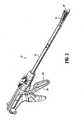
- Surgical stapler 10includes a trigger assembly 30, a body portion 12, a staple cartridge 40, and an anvil assembly 70.
- Trigger assembly 30includes a pivotal trigger 32. Pivotal movement of trigger 32 during an actuation sequence of trigger 32 translates pivotal movement of trigger 32 into linear movement of a drive mechanism (not shown).
- the drive mechanismis operatively coupled to an actuation sled in staple cartridge 40 to translate linear movement of the drive mechanism to linear movement of the actuation sled.
- Stapler 10is movable such that a portion of body tissue (not shown) may be positioned between anvil assembly 70 and staple cartridge 40. Actuation of stapler 10 moves anvil assembly 70 towards staple cartridge 40 thereby grasping or retaining the portion of body tissue therebetween. In addition, once the portion of body tissue is grasped between anvil assembly 70 and staple cartridge 40, continued actuation of stapler 10 discharges staples 50 ( FIG.3 ) through the portion of body tissue and against anvil assembly 70 to form completed staples 50.
- the presently disclosed staple drive assembly 100may be incorporated into staple cartridge 40 of surgical stapler 10 disclosed in U.S. Patent No. 6,669,073 .
- staple drive assembly 100may be incorporated into other known stapling devices including open-type surgical stapling devices, such as the open surgical staplers shown and described U.S. Patents 4,955,959 ; 4,978,049 ; 5,395,034 ; 5,630,541 ; 5,662,258 ; 6,131,789 and D278,081 and other endoscopic or laparoscopic surgical stapling devices, such as the endoscopic staplers shown and described in published U.S. Patent Applications 2004/0232195 ; 2004/0232197 and 2004/0232199 .
- open-type surgical stapling devicessuch as the open surgical staplers shown and described U.S. Patents 4,955,959 ; 4,978,049 ; 5,395,034 ; 5,630,541 ; 5,662,258 ; 6,131,789 and D278,081
- other endoscopic or laparoscopic surgical stapling devicessuch as the endoscopic staplers shown and described in published U.S. Patent Applications 2004/
- FIG. 3illustrates a staple cartridge 40' including the staple drive assembly shown in FIG. 1 .
- Staple cartridge 40'includes a plurality of fasteners or staples 50 and a corresponding number of staple pockets or retention slots 60.
- a tissue contacting surface 44is defined by a top surface of staple cartridge 40'.
- a guide channel 42extends substantially the length of staple cartridge 40' and is adapted for slidably receiving guide member 150 of actuation sled 110 as shown in FIG. 4 .
- sled 110is shown positioned at the proximal end of cartridge 40' with guide member 150 disposed in guide channel 42.
- Guide channel 42cooperates with guide member 150 for aligning and positioning actuation sled 110 in staple cartridge 40' as it translates longitudinally from a proximal end to a distal end of staple cartridge 40'.
- Guide channel 42may also facilitate passage of a knife blade (not shown) through cartridge 40', such as by mounting a knife blade to guide member 150.
- FIG. 5a cross-sectional view taken along line 5-5 of FIG. 4 , actuation sled 110 is shown disposed in the proximal end of staple cartridge 40' in a first or ready position.
- actuation sled 110In the ready position, actuation sled 110 is capable of translating distally through staple cartridge 40' (i.e. in the direction indicated by arrow A) and sequentially engaging staple pushers 160 ( FIG. 3 ) as discussed in detail hereinbelow.
- Actuation sled 110is translatable along a longitudinal axis of staple cartridge 40' from its ready position to a second or end position located in a distal portion of staple cartridge 40'.
- Each staple pusher 160includes a first cam member 162, a second cam member 164, and at least one prong or pusher plate 166.
- each staple pusher 160includes three pusher plates 166 that are laterally and longitudinally spaced apart from each other.
- first and second cam members 162, 164 and pusher plates 166lie in a plane parallel to a longitudinal axis of staple cartridge 40'.
- each pusher plate 166includes a leading edge 166a and a trailing edge 166b.
- pusher plates 166may be longitudinally spaced apart or staggered such that the longitudinal spacing between leading edges 166a of adjacent pusher plates 166 is about two-thirds the length of retention slot 60 or about two-thirds the length of an adjacent pusher plate 166. Further still, each pusher plate 166 includes a top surface 166c that is adapted for releasably engaging a backspan 52 of a staple 50 (see FIG. 1 ). Each retention slot 60 of staple cartridge 40' is configured for releasably receiving a staple 50 and a pusher plate 166 (see FIG. 3 ). Additionally, each staple includes two legs 54.
- staple pusher 160includes prongs or pusher plates 166 that are laterally and longitudinally spaced apart as well as first and second cam members 162, 164 interposed between adjacent pusher plates 166. More specifically, as discussed hereinabove, in one embodiment of the present disclosure, each staple pusher 160 includes a plurality of pusher plates 166 that are substantially parallel to a longitudinal axis of staple cartridge 40' and parallel to a centerline CL of each staple pusher 160 ( FIG. 8 ). Additionally, first and second cam members 162, 164 are also substantially parallel to centerline CL ( FIG. 8 ). Staple pusher 160, as viewed from left to right in FIG. 8 (i.e.
- staple pusher 160has an arrangement where pusher plates 166 are longitudinally staggered from a distal portion of staple pusher 160 to a proximal portion of staple pusher 160 as seen in FIG. 8 .
- First and second cam members 162, 164include respective first and second cam surfaces 162a, 162b and 164a, 164b ( FIGS. 9 and 10 ). At the intersection of first and second cam surfaces 162a, 162b and 164a, 164b are respective transition points 162c, 164c. A plane T ( FIG. 10 ) extending through transition points 162c, 164c is parallel to respective tops 163, 165 of cam members 162, 164. In one embodiment, first cam surfaces 162a, 164a define a first engagement or receiving angle with respect to tops 163, 165 of respective first and second cam members 162, 164. Second cam surfaces 162b, 164b define a second engagement or receiving angle with respect to plane T.
- First and second receiving anglesare complementary to respective first and second drive angles of camming members 120, 140 of actuation sled 110 as discussed in detail hereinbelow.
- the first receiving anglesmay be in a range of about 15° to about 55° while the second receiving angles may be in a range of about 5° to about 35°.
- the first receiving anglesmay be in a range of about 25° to about 45° while the second receiving angles may be in a range of about 10° to about 30°.
- first receiving anglesmay be in a range of about 30° to about 40° while second receiving angles may be in a range of about 15° to about 25°.
- staple pusher 260is illustrated and includes the same or substantially similar components to staple pusher 160.
- Each staple pusher 260includes a first cam member 262, a second cam member 264, and a single prong or pusher plate 266.
- first and second cam members 262, 264 and pusher plates 266lie in a plane parallel to a longitudinal axis of staple cartridge 40'.
- each pusher plate 266includes a leading edge 266a and a trailing edge 266b.
- each pusher plate 266includes a top surface 266c that is adapted for releasably engaging a backspan 52 of a staple 50 (see FIG. 1 ).
- Each retention slot 60 of staple cartridge 40'is configured for releasably receiving a staple 50 and a pusher plate 266 (see FIG. 3 ).
- Staple pusher 260includes a prong or a pusher plate 266 that separates first and second cam members 262, 264. More specifically, each staple pusher 260 includes a single pusher plate 266 that is substantially parallel to a longitudinal axis of staple cartridge 40' and parallel to a centerline CL of each staple pusher 260 ( FIG. 27 ). Additionally, first and second cam members 262, 264 are also substantially parallel to centerline CL ( FIG. 27 ).
- First and second cam members 262, 264include respective first and second cam surfaces 262a, 262b and 264a, 264b ( FIG. 26 ). At the intersection of first and second cam surfaces 262a, 262b and 264a, 264b are respective transition points 262c, 264c. A plane T ( FIG. 26 ) extending through transition points 262c, 264c is parallel to respective tops 263, 265. In one embodiment, first cam surfaces 262a, 264a define a first engagement or receiving angle with respect to tops 263, 265 of respective first and second cam members 262, 264. Second cam surfaces 262b, 264b define a second engagement or receiving angle with respect to plane T.
- First and second receiving anglesare complementary to respective first and second drive angles of camming members 120, 140 as discussed in detail hereinbelow.
- the first receiving anglesmay be in a range of about 15° to about 55° while the second receiving angles may be in a range of about 5° to about 35°.
- the first receiving anglesmay be in a range of about 25° to about 45° while the second receiving angles may be in a range of about 10° to about 30°.
- first receiving anglesmay be in a range of about 30° to about 40° while second receiving angles may be in a range of about 15° to about 25°.
- Each staple pusher 360includes a first cam member 362, a second cam member 364, and two prongs or pusher plates 366 that are laterally and longitudinally spaced apart from each other.
- first and second cam members 362, 364 and pusher plates 366lie in a plane parallel to a longitudinal axis of staple cartridge 40'.
- each pusher plate 366includes a leading edge 366a and a trailing edge 366b.
- Pusher plates 366may be longitudinally spaced apart or staggered such that the longitudinal spacing between leading edges 366a of adjacent pusher plates 366 is about two-thirds the length of retention slot 60 or about two-thirds the length of pusher plate 366. Further still, each pusher plate 366 includes a top surface 366c that is adapted for releasably engaging a backspan 52 of a staple 50 (see FIG. 1 ). Each retention slot 60 of staple cartridge 40' is configured for releasably receiving a staple 50 and a pusher plate 366 (see FIG. 3 ).
- First and second cam members 362, 364include respective first and second cam surfaces 362a, 362b and 364a, 364b ( FIGS. 28 and 29 ). At the intersection of first and second cam surfaces 362a, 362b and 364a, 364b are respective transition points 362c, 364c. A plane T ( FIG. 28 ) extending through transition points 362c, 364c is parallel to respective tops 363, 365.
- first cam surfaces 362a, 364adefine a first engagement or receiving angle with respect to tops 363, 365 of respective first and second cam members 362, 364.
- Second cam surfaces 362b, 364bdefine a second engagement or receiving angle with respect to plane T.
- First and second receiving anglesare complementary to respective first and second drive angles of camming members 120, 140 as discussed in detail hereinbelow.
- the first receiving anglesmay be in a range of about 15° to about 55° while the second receiving angles may be in a range of about 5° to about 35°.
- the first receiving anglesmay be in a range of about 25° to about 45° while the second receiving angles may be in a range of about 10° to about 30°.
- first receiving anglesmay be in a range of about 30° to about 40° while second receiving angles may be in a range of about 15° to about 25°.
- First and second camming members 120, 140each include a first or leading cam wedge 122, 142, respectively, that is laterally and longitudinally spaced apart from a second or trailing cam wedge 124, 144, respectively.
- the lateral and longitudinal offset distances of each pair of camming wedgessubstantially corresponds to the lateral and longitudinal offset distances between corresponding cam members 162, 164.
- First cam wedges 122, 142are laterally and longitudinally spaced from second cam wedges 124, 144, respectively, by a substantially identical amount such that first and second camming members 120, 140 are symmetrical about a central longitudinal axis of actuation sled 110.
- Leading cam wedges 122, 142include respective first and second drive faces 122a, 122b, 142a, and 142b.
- First drive faces 122a, 142aform first drive angles on camming members 120, 140 with respect to base 112 of actuation sled 110.
- At the intersection of first and second drive faces 122a, 142a and 122b, 142bare respective transition points 123, 143.
- a plane X extending through transition points 123, 143is substantially parallel to base 112.
- Second drive faces 122b, 142bform respective second drive angles on camming members 120, 140 with respect to plane X.
- Plane Xis also substantially parallel to tissue contacting surface 44 of staple cartridge 40'.
- trailing cam wedges 124, 144include respective first and second drive faces 124a, 124b, 144a, and 144b.
- First drive faces 124a, 144aform first drive angles on camming members 120, 140 with respect to base 112 ( FIG. 5 ) of actuation sled 110.
- At the intersection of first and second drive faces 124a, 124b and 144a, 144bare respective transition points 125, 145.
- Plane Xextends through transition points 125, 145 and is substantially parallel to base 112.
- Second drive faces 124b, 144bform respective second drive angles on camming members 120, 140 with respect to plane X.
- first drive anglesmay be in a range of about 15° to about 55° while second drive angles may be in a range of about 5° to about 35°. In another embodiment, first drive angles may be in a range of about 25° to about 45° while second drive angles may be in a range of about 10° to about 30°. In a further embodiment, first drive angles may be in a range of about 30° to about 40° while second drive angles may be in a range of about 15° to about 25°.
- FIGS. 16-18Interaction between actuation sled 110 and staple pusher 160 of staple drive assembly 100 is shown in FIGS. 16-18 and discussed in detail hereinafter.
- actuation sled 110translates distally through staple cartridge 40' in the direction indicated by arrow A (see also FIG. 5 ) causing first drive face 122a to slidably engage first cam surface 162a and urge staple pusher 160 from its first or rest position in a generally vertical direction as indicated by arrow B.
- first drive face 124asubstantially simultaneously slidably engages first cam surface 164a thereby urging staple pusher 160 in a generally vertical direction as indicated by arrow B. Since cam surfaces 162a and 164a are longitudinally offset, staple pusher 160 is driven in a controlled and balanced manner and any tendency of staple pusher 160 to tilt or rotate counterclockwise (as viewed in FIGS. 16-17 ) is minimized as staple pusher 160 is driven through retainer slot 60.
- First drive faces 122a, 124a and respective first cam surfaces 162a, 164ahave complementary angles that maximize translation of longitudinal motion of actuation sled 110 to vertical motion of staple pusher 160.
- actuation sled 110further urges staple pusher 160 generally vertically to an intermediate position, such that second drive faces 122b, 124b slidably engage respective second cam surfaces 162b, 164b while first drive faces 122a, 124a substantially simultaneously disengage from respective first cam surfaces 162a, 164a.
- second drive faces 122b, 124b and respective second cam surfaces 162b, 164bhave complementary angles to maximize translation of longitudinal motion of actuation sled 110 to vertical motion of staple pusher 160.
- second drive faces 122b, 124b and respective second cam surfaces 162b, 164bcontinue to control the advancement of staple pusher 160 so as to minimize any tendency of staple pusher 160 to tilt or rotate in a counterclockwise direction as viewed in FIGS. 16-17 .
- actuation sled 110continues to urge staple pusher 160 vertically to its second or end position immediately prior to the disengagement between second drive faces 122b, 124b and respective second cam surfaces 162b, 164b.
- second camming member 140 and staple pusher 160Since the interaction between second camming member 140 and staple pusher 160 is substantially identical to the intersection of first camming member 120 and pusher 160, the intersection of second camming member 140 and staple pusher 160 will not be described in detail herein.
- first and second camming members 120, 140Longitudinal motion of actuation sled 110 in the direction indicated by arrow A results in first and second camming members 120, 140 slidably engaging staple pushers 160 as shown in FIGS. 16-18 .
- Sliding engagement between leading cam wedges 122, 142 and first cam members 162 in cooperation with the substantially simultaneous engagement between trailing cam wedges 124, 144 and second cam members 164improve the longitudinal stability of the staple pushers 160 during vertical motion as follows.
- Leading cam wedges 122, 142are longitudinally spaced apart from trailing cam wedges 124, 144 by a predetermined amount.
- first and second cam members 162, 164are longitudinally spaced apart by a comparable, but complementary amount, longitudinal movement of actuation sled 110 results in the substantially simultaneous, but offset engagement of leading cam wedges 122, 124 and trailing cam wedges 124, 144 with respective first and second cam members 162, 164 thereby transferring the longitudinal movement of actuation sled 110 to vertical movement of staple pusher 160 at longitudinally spaced apart impact points.
- longitudinal movement of actuation sled 110By transferring longitudinal movement of actuation sled 110 to each staple pusher 160 at two longitudinally spaced apart impact points, substantially balanced vertical movement of each staple pusher 160 is achieved.
- first and second camming members 120, 140 and respective first and second cam members 162, 164are two point contact between first and second camming members 120, 140 and respective first and second cam members 162, 164 throughout the vertical travel of each staple pusher 160.
- pivoting or tilting of each staple pusher 160is minimized due to the two-point contact arrangement.
- Minimizing pivoting or tilting of each staple pusher 160 during vertical travelfurther minimizes pivoting or tilting of each staple 50 as each staple 50 is driven vertically in its respective retention slot 60. This provides more precise contact of a staple with an anvil pocket (not shown) and thus, improved staple formation.
- cam wedges 122, 124 of first camming member 120 and cam wedges 142, 144 of second camming member 140inhibits "rocking" of staple pusher 160.
- "Rocking" of staple pushersmay occur when the lifting force applied to the staple pusher by the actuation sled is not balanced creating a tendency for the staple pusher to "rock” in a direction that is transverse to the movement of the actuation sled. This "rocking" movement may cause misalignment of the staple during a firing sequence resulting in non-uniform staple formation.
- actuation sled 110may cause a "front jump" staple formation wherein the rear leg of a staple exits the staple cartridge at an angle and enters the anvil pocket at the same location as the front leg of the same staple.
- actuation sled 110contacts staple pusher 160 at two laterally spaced contact points substantially simultaneously, thereby imparting a lifting force to staple pusher 160 that is substantially balanced between first and second cam members 162, 164. Therefore, engagement of actuation sled 110 with staple pusher 160 results in substantially even vertical motion of staple pusher 160 and inhibits "rocking" of staple pusher 160 and inhibits front jump staple formation.
- each cam wedge(122, 124, 142, 144) defines a plurality of receiving angles that are complementary to drive angles defined by cam members 162, 164.
- first drive angleis greater than the second drive angle
- single point contact between the staple pusher and the cam wedgemay occur. Instability of the staple pusher due to such single point contact can also result in tilting or rotation of the staple pusher during firing. Such instability is most likely to occur as the staple pusher transitions from contacting one drive surface to the other drive surface.
- unbalanced vertical movement of staple pusher 160can cause staple pusher 160 to travel vertically at an angle such that top surfaces 166c ( FIG.
- staple pusher 160are not substantially parallel to tissue contacting surface 44 or backspan 52 of staple 50 ( FIG. 3 ). This may lead to improperly formed staples, misalignment of the staples with the anvil pockets, or misalignment of the staples with the retention slots.
- an angular differentialis defined wherein the angular differential minimized "rotation" of staple pusher 160.
- Interaction between actuation sled 110 and staple pushers 260, 360is substantially similar to the interaction described hereinabove between actuation sled 110 and staple pusher 160 and will not be discussed in detail. It is sufficient to note that staple pushers 260, 360 may be freely substituted for staple pusher 160.
- Staple drive assembly 200includes an actuation sled 210 ( FIGS. 19-23 ) and at least one staple pusher 160 ( FIGS. 6-10 ).
- Actuation sled 210is adapted and configured for use in staple cartridge 40' as an alternative for actuation sled 110.
- actuation sled 210includes a first camming member 220, a second camming member 240, and a guide member 250.
- First and second camming members 220, 240include respective first or leading cam wedges 222, 242 and respective second or trailing cam wedges 224, 244.
- leading cam wedges 222, 242 of actuation sled 210include first drive faces 222a, 242a and second drive faces 222b, 242b. Interposed between first drive faces 222a, 242a and second drive faces 222b, 242b are respective first and second transition points 223, 243. First drive faces 222a, 242a extend proximally from a distal point 214 both longitudinally and vertically thereby forming a first drive angle with respect to base 212. Trailing cam wedges 224, 244 are longitudinally spaced apart from leading cam wedges 222, 242 by a predetermined distance.
- First drive faces 224a, 244a of trailing cam wedges 224, 244extend both longitudinally and vertically in a proximal direction from respective origin points 214a, 214b to form the first drive angle with respect to base 212.
- a plane X'extending through transition points 223, 243 ( FIG. 23 ) of leading cam wedges 222, 242 is parallel to base 212.
- Second drive faces 222b, 242bform respective second drive angles with respect to plane X'.
- plane X'extends through transition points 225, 245 ( FIG. 23 ) of trailing cam wedges 224, 244 and is substantially parallel to base 212.
- Plane X'is also substantially parallel to tissue contacting surface 44 of staple cartridge 40'.
- Second drive faces 224b, 244bform respective second drive angles with respect to plane X'.
- first drive anglesmay be in a range of about 5° to about 35° while second drive angles may be in a range of about 20° to about 55°.
- first drive anglesmay be in a range of about 10° to about 30° while second drive angles may be in a range of about 25° to about 45°.
- first drive anglesmay be in a range of about 15° to about 25° while the second drive angles may be in a range of about 30° to about 40°.
- actuation sled 210By providing actuation sled 210 with first drive faces 222a, 242a having a flatter initial engaging surface having a lower angle relative to a plane parallel to base 212, interaction between actuation sled 210 and each staple pusher 160 is more controllable. As actuation sled 210 translates through staple cartridge 40' and interacts with each staple pusher as discussed above, actuation sled 210 gradually and controllably urges each staple pusher 160 vertically as actuation sled 210 translates through staple cartridge 40'.
- first drive faces 222a, 224acontact respective second cam surfaces 162b, 164b and urge staple pusher 160 in a generally vertical direction as indicated by arrow B from its first or rest position. Since the first drive angle is defined by first drive faces 222a, 224a and is complementary to the second receiving angle defined by second cam surfaces 162b, 164b, horizontal movement of actuation sled 210 in direction A causes vertical movement of staple pusher 160 in direction B.
- first drive faces 222a, 224adisengage from their respective second cam surfaces 162b, 164b while second drive faces 222b, 224b remain engaged with their respective first cam surfaces 162a, 164a.
- the second drive angle defined by second drive faces 222b, 224bis complementary to the first receiving angle defined by first cam surfaces 162a, 164a further urging staple pusher 160 in the direction of arrow B through an intermediate position.
- actuation sled 210continues to urge staple pusher 160 vertically to its second or end position immediately prior to the disengagement between second drive faces 222b, 224b and respective second cam surfaces 162a, 164a.
- a cam wedge having a first drive angle which is less than the second drive anglecreates multiple contact points between the cam wedge and the staple pusher as the staple pusher transitions from contacting the first drive surface to contacting the second drive surface, thereby further enhancing the stability of the staple pusher during firing.
- providing a first drive angle less than the second drive angleminimizes misalignment since there is additional support for the staple pusher during its vertical movement.
- second camming member 240 and staple pusher 160Since the interaction between second camming member 240 and staple pusher 160 is substantially identical to the interaction between first camming member 220 and staple pusher 160, the interaction between second camming member 240 and staple pusher 160 will not be described in further detail herein. It is sufficient to note that staple pushers 260, 360 may be freely substituted for staple pusher 160.
- leading cam wedges 222, 242 and first cam members 162in cooperation with the substantially simultaneous engagement between trailing cam wedges 224, 244 and second cam members 164 is substantially similar to that discussed hereinabove for staple drive assembly 100 and improves the longitudinal stability of the staple pushers 160 during vertical motion.
- Interaction between actuation sled 210 and staple pushers 260, 360is substantially similar to the interaction described hereinabove between actuation sled 210 and staple pusher 160 and will not be discussed in detail.
- Staple drive assembly 300includes an actuation sled 310 ( FIGS. 30-34 ) and at least one staple pusher 160 ( FIGS. 6-10 ).
- Actuation sled 310is adapted and configured for use in staple cartridge 40' as an alternative for actuation sled 110 or actuation sled 210.
- actuation sled 310includes a first camming member 320, a second camming member 340, and a guide member 350.
- First and second camming members 320, 340include respective first or leading cam wedges 322, 342 and respective second or trailing cam wedges 324, 344.
- trailing cam wedges 324, 344are laterally and longitudinally spaced apart from leading cam wedges 322, 342 by a predetermined distance.
- Leading cam wedges 322, 342include leading drive faces 322a, 342a while trailing cam wedges 324, 344 include trailing drive faces 324a, 344a.
- Drive faces 324a, 344a of trailing cam wedges 324, 344extend both longitudinally and vertically in a proximal direction from respective origin points 314a, 314a.
- Drive faces 322a, 342a of leading cam wedgesalso extend both longitudinally and vertically in a proximal direction from respective origin points 314a, 316b.
- Drive faces 322a, 342a, 324a, 344aeach form a drive angle with respect to base 312 wherein the drive angle is substantially identical for drive faces 322a, 342a, 324a, 344a.
- the drive anglemay be in a range of about 15° to about 25°.
- the drive anglemay be in a range of about 10° to about 30°.
- the drive anglemay be in a range of about 5° to about 35°.
- FIGS. 35-36the interaction between actuation sled 310 and staple pusher 160 is illustrated in FIGS. 35-36 and discussed in detail hereinafter.
- actuation sled 310moves distally through staple cartridge 40' (see FIG. 5 ) in a generally horizontal direction as indicated by arrow A
- drive faces 322a, 324aengage cam surfaces 162, 164 of staple pusher 160 and urge staple pusher 160 in a generally vertical direction as indicated by arrow B from its first or rest position.
- cam surfaces 162, 164define receiving angles that are complementary to the drive angle formed by drive faces 322a, 324a.
- Cam surfaces 162, 164are laterally and longitudinally spaced apart so that the spacing of cam surfaces 162, 164 corresponds to the lateral and longitudinal spaced of the cam wedge drive faces. As actuation sled 310 moves distally through staple cartridge 40', cam surfaces 162, 164 of staple pusher 160 maintain their engagement with drive faces 322a, 324a of actuation sled 310. As will be appreciated, the lateral and longitudinal spacing of the cam wedges and cam surfaces provides improved stability to the staple pusher during firing, as described above, albeit without the varied drive angles of the drive surfaces.
- second camming member 340 and staple pusher 160Since the interaction between second camming member 340 and staple pusher 160 is substantially identical to the interaction between first camming member 320 and staple pusher 160, the interaction between second camming member 340 and staple pusher 160 will not be described in further detail herein. It is sufficient to note that staple pushers 260, 360 may be freely substituted for staple pusher 160.
- leading cam wedges 322, 342 and first cam members 162in cooperation with the substantially simultaneous engagement between trailing cam wedges 324, 344 and second cam members 164 is substantially similar to that discussed hereinabove for staple drive assembly 100, 200 and improves the longitudinal stability of the staple pushers 160 during vertical motion.
- Interaction between actuation sled 310 and staple pushers 260, 360is substantially similar to the interaction described hereinabove between actuation sled 310 and staple pusher 160 and will not be discussed in detail.
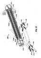
- Staple drive assembly 400includes an actuation sled 410 ( FIGS. 37-41 ) and at least one staple pusher 460 ( FIGS. 42A-42B ).
- Actuation sled 410is adapted and configured for use in staple cartridge 40' ( FIG. 4 ).
- staple pusher 460includes a first cam member 462, a second cam member 464, and at least one prong or pusher plate 466.
- staple pusher 460includes three pusher plates 466 that are laterally spaced apart from each other by first and second cam members 462, 464.
- first and second cam members 462, 464 and pusher plates 466lie in a plane parallel to the longitudinal axis of staple cartridge 40'.
- Each pusher plate 466includes a leading edge 466a, a trailing edge 466b, and a top surface 466c.
- one pusher plate 466may be longitudinally spaced such that pusher plates 466 are in a staggered orientation with respect to each other such that the two outside pusher plates are laterally aligned with each other, but the middle pusher plate is displaced from lateral alignment with the side pusher plates.
- An example of a suitable staple pusheris disclosed in U.S. Patent No. 4,978,049 to Green , currently owned by Tyco Healthcare Group LP.
- First and second cam members 462, 464include respective cam surfaces 462a a, 464a ( FIG. 42A ).
- cam surfaces 462a, 464adefine an engagement or receiving angle with respect to tops 463, 465 of respective first and second cam members 462, 464.
- the receiving angleis complementary to a first drive angle of camming members 420, 440 of actuation sled 410 as discussed in detail hereinbelow.
- the receiving anglemay be in a range of about 15° to about 25°.
- the receiving anglemay be in a range of about 17° to about 23°.
- the receiving anglemay be in a range of about 19° to about 21°.
- actuation sled 410 of staple drive assembly 400includes first and second camming members 420, 440 each having a first cam wedge 422, 442, respectively, that is laterally spaced apart from a second cam wedge 424, 444, respectively.
- First cam wedges 422, 442are laterally spaced from second cam wedges 424, 444, respectively, by a substantially identical amount such that first and second camming members 420, 440 are substantially symmetrical about a central longitudinal axis of actuation sled 410.
- Each cam wedge 422, 424, 442, 444includes a plurality of drive faces as shown in FIGS.
- a plane Yextends through the intersection between drive faces "a” and "b.” Plane Y is substantially parallel to a base 412 and to tissue contacting surface 44 of staple cartridge 40' (see FIG. 3 ).
- First cam wedge 422will be discussed in detail below to illustrate the relationship between the drive faces with cam wedges 424, 442, and 444 having substantially identical relationships.
- First cam wedge 424 of cam member 420includes first through fourth drive faces 424a, 424b, 424c, and 424d as shown in FIG. 41 .
- First drive face 422adefines a first angle with respect to base 412 while second drive face 422b defines a second drive angle with respect to plane Y.
- the slope of drive faces 422c and 422dare substantially identical to the slopes of drive faces 422a and 422b respectively.
- the first and third drive anglesi.e. defined by drive faces 422a, 442c
- the first and third drive anglesmay be in a range of about 15° to about 25°.
- the first and third drive anglesmay be in a range of about 17° to about 23°.
- first and third drive anglesmay be in a range of about 19° to about 21°.
- the second drive anglei.e. defined by drive faces 422b, 422d
- the second drive anglemay be in a range of about 26° to 36°.
- the second drive anglemay be in a range of about 28° to 34°.
- the second drive anglemay be in a range of about 30° to about 32°.
- FIGS. 43-44Interaction between actuation sled 410 and staple pusher 460 of staple drive assembly 400 is shown in FIGS. 43-44 and discussed in detail hereinafter.
- actuation sled 410translates distally through staple cartridge 40' in the direction indicated by arrow A causing cam wedges 422, 424 of first cam member 420 to slidably engage staple pusher 460.
- first drive faces 422a, 424asubstantially simultaneously slidably engage respective cam surfaces 462a, 464a and urge staple pusher 460 from its first or rest position in a generally vertical direction as indicated by arrow B.
- the first and third drive angles of cam wedges 422, 424, 442, and 444are complementary to the first receiving angle of cam surfaces 462a, 464a.
- actuation sled 410moves distally with drive faces 422a, 424a in slidable engagement with respective cam surfaces 462a, 464a (i.e. engaging the first drive angle)
- top surfaces 466c of pusher plates 466engage backspan 52 of staple 50 and urge staple 50 in a substantially vertical direction and engages tissue in contact with tissue contacting surface 44.
- cam surfaces 462a, 464aslidably engage respective second drive faces 422b, 424b continuing to urge staple 50 vertically. As illustrated in FIG.
- first drive faces 422a, 424aare spaced apart from third drive faces 422c, 424c by a predetermined distance thereby further minimizing kicking of staple pusher 460 as staple 50 engages tissue and anvil assembly 70, respectively.
- second camming member 440 and staple pusher 460Since the interaction between second camming member 440 and staple pusher 460 is substantially identical to the interaction of first camming member 420 and pusher 460, the interaction of second camming member 440 and staple pusher 460 will not be described in detail herein.
- Staple drive assembly 500includes actuation sled 510 ( FIGS. 45-49 ) having first and second camming members 520, 540 each having a first cam wedge 522, 542, respectively, that is laterally spaced apart from a second cam wedge 524, 544, respectively.
- First cam wedges 522, 542are laterally spaced from second cam wedges 524, 544, respectively, by a substantially identical amount such that first and second camming members 520, 540 are substantially symmetrical about a central longitudinal axis of actuation sled 510.
- Each cam wedge 522, 524, 542, 544includes a plurality of drive faces as shown in FIGS. 45-46 where each of the respective drive faces are indicated by reference characters "a-d.”
- a plane Yextends through the intersection between drive faces "a" and "b.” Plane Y is substantially parallel to a base 512 and to tissue contacting surface 44 of staple cartridge 40' ( FIG. 3 ).
- first cam wedges 522, 542are longitudinally spaced from second cam wedges 524, 544.
- First cam wedge 522will be discussed in detail below to illustrate the relationship between the drive faces with cam wedges 524, 542, and 544 having substantially identical relationships.
- First cam wedge 522 of cam member 520includes first through fourth drive faces 522a, 522b, 522c, and 522d as shown in FIG. 48 .
- First drive face 522adefines a first angle with respect to base 512 while second drive face 522b defines a second drive angle with respect to plane Y.
- the slope of drive faces 522c and 522dare substantially identical to the slopes of drive faces 522a and 522b respectively.
- the first and third drive anglesi.e. defined by drive faces 522a, 542c
- the first and third drive anglesmay be in a range of about 15° to about 55°.
- the first and third drive anglesmay be in a range of about 25° to about 45°.
- first and third drive anglesmay be in a range of about 30° to about 40°.
- the second drive anglei.e. defined by drive faces 522b, 522d
- the second drive anglemay be in a range of about 5° to 35°.
- the second drive anglemay be in a range of about 10° to 30°.
- the second drive anglemay be in a range of about 15° to about 25°.
- FIGS. 50-51Interaction between actuation sled 510 and staple pusher 160 ( FIG. 6 ) of staple drive assembly 500 is shown in FIGS. 50-51 and discussed in detail hereinafter.
- actuation sled 510translates distally through staple cartridge 40' in the direction indicated by arrow A causing first drive face 522a to slidably engage first cam surface 162b and urge staple pusher 160 from its first or rest position in a generally vertical direction as indicated by arrow B.
- first drive face 524aslidably engages first cam surface 16b thereby urging staple pusher 160 in a generally vertical direction as indicated by arrow B.
- cam surfaces 162b, 164b and first drive faces 522a, 524aare longitudinally offset, staple pusher 160 is driven in a balanced manner to minimize tipping or tilting of staple pusher 160 as it is driven through retainer slot 60.
- First drive faces 522a, 524a and respective first cam surfaces 162b, 164bhave complementary angles that maximize translation of longitudinal motion of actuation sled 510 to vertical motion of staple pusher 160.
- actuation sled 510further urges staple pusher 160 generally vertically to an intermediate position, such that second drive faces 522b, 524b slidably engage respective second cam surfaces 162a, 164b while first drive faces 522a, 524a substantially simultaneously disengage from respective first cam surfaces 162b, 164b.
- second drive faces 522b, 524b and respective second cam surfaces 162a, 164ahave complementary angles to maximize translation of longitudinal motion of actuation sled 510 to vertical motion of staple pusher 160.
- actuation sled 510continues to urge staple pusher 160 vertically to its second or end position immediately prior to the disengagement between second drive faces 522b, 524b and respective second cam surfaces 162a, 164a.
- second camming member 540 and staple pusher 160Since the interaction between second camming member 540 and staple pusher 160 is substantially identical to the intersection of first camming member 520 and pusher 160, the intersection of second camming member 540 and staple pusher 160 will not be described in detail herein.
- first and second camming members 520, 540Longitudinal motion of actuation sled 510 in the direction indicated by arrow A results in first and second camming members 520, 540 slidably engaging staple pushers 160 as shown in FIGS. 50-51 .
- Sliding engagement between leading cam wedges 522, 542 and second cam members 164 in cooperation with the substantially simultaneous engagement between trailing cam wedges 524, 544 and first cam members 162improve the longitudinal stability of the staple pushers 160 during vertical motion as follows.
- Leading cam wedges 522, 542are longitudinally spaced apart from trailing cam wedges 524, 544 by a predetermined amount.
- first and second cam members 162, 164are longitudinally spaced apart by a comparable, but complementary amount
- longitudinal movement of actuation sled 510results in the substantially simultaneous engagement of leading cam wedges 522, 524 and trailing cam wedges 524, 544 with respective first and second cam members 162, 164 thereby transferring the longitudinal movement of actuation sled 510 to vertical movement of staple pusher 160 at longitudinally spaced apart impact points.
- first and second camming members 520, 540 and respective first and second cam members 162, 164are two point contact between first and second camming members 520, 540 and respective first and second cam members 162, 164 throughout the vertical travel of each staple pusher 160.
- pivoting or tilting of each staple pusher 160is minimized due to the two-point contact arrangement.
- Minimizing pivoting or tilting of each staple pusher 160 during vertical travelfurther minimizes pivoting or tilting of each staple 50 as each staple 50 is driven vertically in its respective retention slot 60. This provides more precise contact of a staple with an anvil pocket (not shown) and thus, improved staple formation.
- Interaction between actuation sled 510 and staple pushers 260, 360is substantially similar to the interaction described hereinabove between actuation sled 510 and staple pusher 160 and will not be discussed in detail. It is sufficient to note that staple pushers 260, 360 may be freely substituted for staple pusher 160.
- FIGS. 52-56Further embodiments of the present disclosure are illustrated in FIGS. 52-56 and discussed in detail hereinafter.
- the embodiments that are illustrated in FIGS. 52-56include a cam member or actuation bar.
- An example of a suitable cam bar and associated apparatusis disclosed in U.S. Patent No. 6,619,529 to Green et al ., currently owned by Tyco Healthcare Group LP.
- the staple cartridge 40'( FIG. 3 ) may include longitudinal slots as disclosed in the '529 for providing lateral stability to the cam bars as they translate longitudinally through staple cartridge 40'. Referring initially to FIG. 52 , a portion of a cam bar or actuation member 600 is illustrated.
- Actuation member 600includes a distal end 610 wherein distal end 610 includes the same or substantially similar components as included in actuation sled 110 ( FIG. 11 ).
- Distal end 610includes a base 612, a first camming member 620, and a second camming member 640 (not shown).
- First and second camming members 620, 640include respective first or leading cam wedges 622, 642 and respective second or trailing cam wedges 624, 644.
- the configuration and relationships between the components of distal end 610are substantially similar to those components of actuation sled 110 and will not be described in detail herein.
- distal end 610includes actuation sled 110 using reference characters 6xx in lieu of 1xx used in describing actuation sled 110.
- actuation member 600 and distal end 610may be substituted for actuation sled 110 in staple cartridge 40' ( FIG. 4 ).
- the interaction of distal end 610 and staple pusher 160 ( FIG. 6 )is substantially similar to the interaction of actuation sled 110 and staple pusher 160 (see FIGS. 16-17 ) and will not be discussed in detail herein.
- distal end 610is adapted to cooperate with staple pusher 260 ( FIG. 26 ) or staple pusher 360 ( FIG. 28 ).
- cam wedges 622, 642are laterally and longitudinally offset and engage corresponding surfaces on the staple pusher (not shown) for improving the stability of the staple pusher during firing, as described above with respect to cam wedges 122, 142.
- an actuation member 700includes a distal end 710 having the same or substantially similar components as included in actuation sled 210 ( FIG. 19 ).
- Distal end 710includes a base 712, a first camming member 720, and a second camming member 740 (not shown).
- First and second camming members 720, 740include respective first or leading cam wedges 722, 742 and respective second or trailing cam wedges 724, 744.
- the configuration and relationships between the components of distal end 710are substantially similar to those components of actuation sled 210 and will not be described in detail herein.
- distal end 710includes actuation sled 210 using reference characters 7xx in lieu of 2xx used in describing actuation sled 210.
- actuation member 700 and distal end 710may be substituted for actuation sled 210 in staple cartridge 40'.
- the interaction of distal end 710 and staple pusher 160 ( FIG. 6 )is substantially similar to the interaction of actuation sled 210 and staple pusher 160 (see FIGS. 22-23 ) and will not be discussed in detail herein.
- distal end 710is adapted to cooperate with staple pusher 260 ( FIG. 26 ) or staple pusher 360 ( FIG. 28 ).
- the lateral and longitudinal offset of the cam wedgesare enhanced by providing drive surfaces wherein the first drive angle is less than the second drive angle. This arrangement of drive angles enhances staple pusher stability, thereby minimizing tilting or rotation and further reduces uneven firing of staples 50.
- FIG. 54illustrates a portion of an actuation member 800 and includes a distal end 810 having the same or substantially similar components as actuation sled 310 ( FIG. 30 ).
- Distal end 810includes a base 812, a first camming member 820, and a second camming member 840 (not shown).
- First and second camming members 820, 840include respective first or leading cam wedges 822, 842 and respective second or trailing cam wedges 824, 844.
- the configuration and relationships between the components of distal end 810are substantially similar to those components of actuation sled 310 and will not be described in detail herein.
- distal end 810includes actuation sled 310 using reference characters 8xx in lieu of 3 xx used in describing actuation sled 310.
- actuation member 800 and distal end 810may be substituted for actuation sled 310 in staple cartridge 40'.
- the interaction of distal end 810 and staple pusher 160( FIG. 6 ) is substantially similar to the interaction of actuation sled 310 and staple pusher 160 (see FIGS. 35-36 ) and will not be discussed in detail herein.
- distal end 810is adapted to cooperate with staple pusher 260 ( FIG. 26 ) or staple pusher 360 ( FIG. 28 ). In this embodiment, the lateral and longitudinal offset of the cam wedges improves the stability of the staple pusher during firing.
- FIG. 55illustrates a portion of an actuation member 900 and includes a distal end 910 having the same or substantially similar components as actuation sled 410 ( FIG. 37 ).
- Distal end 910includes a base 912, a first camming member 920, and a second camming member 940 (not shown).
- First and second camming members 920, 940include respective first or leading cam wedges 922, 942 and respective second or trailing cam wedges 924, 944.
- the configuration and relationships between the components of distal end 910are substantially similar to those components of actuation sled 410 and will not be described in detail herein.
- distal end 910includes actuation sled 410 using reference characters 9xx in lieu of 4xx used in describing actuation sled 410.
- actuation member 900 and distal end 910may be substituted for actuation sled 410 in staple cartridge 40'.
- the interaction of distal end 910 and staple pusher 460( FIG. 42A ) is substantially similar to the interaction of actuation sled 410 and staple pusher 460 (see FIGS. 43-44 ) and will not be discussed in detail herein.
- FIG. 56illustrates a portion of an actuation member 1000 and includes a distal end 1010 having the same or substantially similar components as actuation sled 510 ( FIG. 45 ).
- Distal end 1010includes a base 1012, a first camming member 1020, and a second camming member 1040 (not shown).
- First and second camming members 1020, 1040include respective first or leading cam wedges 1022, 1042 and respective second or trailing cam wedges 1024, 1044.
- the configuration and relationships between the components of distal end 1010are substantially similar to those components of actuation sled 510 and will not be described in detail herein.
- distal end 1010includes actuation sled 510 using reference characters 10xx in lieu of 5xx used in describing actuation sled 510.
- actuation member 1000 and distal end 1010may be substituted for actuation sled 510 in staple cartridge 40'.
- the interaction of distal end 1010 and staple pusher 160( FIG. 6 ) is substantially similar to the interaction of actuation sled 510 and staple pusher 160 (see FIGS. 50-51 ) and will not be discussed in detail herein.
- distal end 1010is adapted to cooperate with staple pusher 260 ( FIG. 26 ) or staple pusher 360 ( FIG. 28 ).
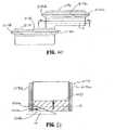
- FIGS. 57-67illustrate further embodiments of the present disclosure.
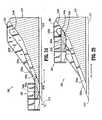
- a staple cartridge 2140includes a tissue contacting portion 2161.
- tissue contacting portion 2161includes first, second, and third tissue contacting surfaces 2161a, 2161b, 2161c.
- tissue contacting surfaces 2161a-2161care planar structures that are substantially parallel to one another, but are not co-planar with one another (i.e. the tissue contacting portion is stepped).
- a set of tissue contacting surfaces 2161 a-cis disposed on each side of knife channel 2148.
- the third tissue contacting surfaces 2161chave a knife channel 2148 defined therein.
- the tissue contacting surfaces 2161 care co-planar with one another.
- first, second, and third tissue contacting surfaces 2161 a, 2161 b, 2161 chave different heights as measured from knife channel 2148. Additionally, each first tissue contacting surface 2161 a is co-planar with one another. Similarly, each second tissue contacting surface 2161b is co-planar with one another. Although the drawings show planar tissue contacting surfaces 2161a-2161c, the present disclosure envisions curved or angled tissue contacting surfaces as well as other kinds of tissue contacting surfaces having other shapes and structures.
- a wall or any other suitable structureinterconnects first and second tissue contacting surfaces 2161a and 2161b.
- a suitable structuresuch as a wall interconnects second and third contacting surfaces 2161b and 2161c.
- the walls or interconnecting structuresmay be oriented orthogonally with respect to the tissue contacting surfaces 2161a-216c. The present disclosure, however, contemplates walls or interconnecting structures oriented in different directions such as angled, curved or other configurations.
- first tissue contacting surface 2161 ahas the least height
- third tissue contacting surface 2161 chas the greatest height
- second tissue contacting surface 2161bhas a height between the heights of first and third tissue contacting surfaces 2161 a, 2161 c. While tissue contacting surfaces 2161a-2161c are shown as decreasing in height from first tissue contacting surface 2161 a to third tissue contacting surface 2161 c, it is envisioned that the heights of each tissue contacting surface may vary depending on the particular surgical procedure. Other features of tissue contacting surfaces 2161a-2161c may also vary according to the circumstances.
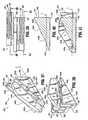
- Each tissue contacting surface 2161a-2161cincludes a plurality of retention slots 2144 formed therein.
- Retention slots 2144are disposed in a plurality of rows 2144a, 2144b, 2144c that are located in tissue contacting surfaces 2161a, 2161b, 2161c respectively.
- the linear rows of retention slots 2144a-care staggered along the longitudinal axis of staple cartridge 2140 as shown in FIGS. 57 and 67 .
- the distal most retention slots 2144 of rows 2144a, 2144care closer to the distal end of cartridge 2140 than the distal most retention slots 2144 of row 2144b.
- the most proximal retention slots 2144 of rows 2144bare closer to the proximal end of cartridge 2140 than the most proximal retention slots 2144 of rows 2144a, 2144c.
- Linear rows of retention slots 2144a-2144c having other suitable arrangementsare within the scope of the present disclosure as long as they are capable of receiving surgical fasteners.
- FIG. 57aillustrates an arrangement of the surgical fasteners 50a-c in the staple cartridge 2140.
- Staple cartridge 2140includes surgical fasteners or staples 50a, 50b, and 50c.
- Each staple 50a, 50b, and 50cincludes a backspan 52a-c.
- Legs 55a of surgical fasteners 50ahave a first leg length "A”
- legs 55b of surgical fasteners 50bhave a second leg length "B”
- legs 55c of surgical fasteners 50chave a third leg length "C.”
- first length "A"is greater than second length "B.”
- second length "B”is greater than third length "C.”
- U.S. Patent Application Publication No. 2007/0131732describes an embodiment of the disclosed fastener arrangement. The present disclosure, however, contemplates other fastener arrangements.
- Surgical fasteners 50a-care configured to operate in conjunction with staple pusher 2160.
- Surgical fasteners 50a-ccooperate with staple pusher 2160 and sled 110 ( FIG. 61 ) such that the longitudinal translation of sled 110 through staple cartridge 2140 urges pushers 2160 in a vertical direction to eject surgical fasteners 50a-c.
- staple pusher 2160includes pusher plates 2166a-c, each of which has a different vertical dimension.
- Pusher plate 2166chas the greatest vertical dimension and cooperates with surgical fastener 50c, which has the smallest leg length.
- Pusher plate 2166ahas the smallest vertical dimension and cooperates with surgical fastener 50a, which has the largest leg length.
- Pusher plate 2166bhas a vertical dimension greater than pusher plate 2166a, but less than pusher plate 2166c and cooperates with surgical fastener 50b, which has an intermediate leg length, between those of surgical fasteners 50a and 50c.
- the surgical fasteners 50care arranged adjacent knife channel 2148.
- Surgical fasteners 50aare adjacent to outer edge of cartridge 2140, and surgical fasteners 50b are disposed therebetween.
- the various sized-staplesare formed against the anvil of the stapler, into the desired shape. It is also envisioned that other arrangements of pusher plates and surgical fasteners may be used.
- staples having different leg lengthsmay be arranged so that the staples with the larger leg lengths are arranged adjacent the knife channel 2148.
- the staple cartridge 2140may have a single planar tissue contacting surface and the anvil member may be provided with more than one tissue contacting surface so as to define more than one gap with respect to the tissue contacting surface of the staple cartridge.
- One or both of the staple cartridge and anvil membermay have stepped surfaces, angled or sloped surfaces, or curved surfaces that are selected to correspond to staples having predetermined leg lengths.
- more than one tissue contacting surfaceis provided, on the staple cartridge, the anvil member, or both, with sloped surfaces extending therebetween.
- the staple pushershave heights corresponding to the different staple sizes.
- the anvil pockets of the anvil assembly, the staple pushers, and/or the actuation sledare arranged to form each of the different sized staples in the desired closed shapes.
- staple cartridge 2140includes at least one double staple pusher 2170, at least one triple staple pusher 2160 and at least one quadruple staple pusher 2180.
- double staple pusher 2170has only two pusher plates 2176
- triple staple pusher 2160has only three pusher plates 2166
- quadruple staple pusher 2180has only four pusher plates 2186.
- the staples and pushersare arranged in a pattern on a first side 2148a of knife channel 2148 and on a second side 2148b of knife channel 2148, so as to form three longitudinal rows of staples on each side of knife channel 2148.
- Double staple pushers 2170are disposed at the proximal end of staple cartridge 2140 and are adapted to deploy the most proximal staples 50b and 50c through retention slots 2144 of rows 2144b and 2144c, respectively.
- One double staple pusher 2170interacts with two most proximal staples 50b and 50c disposed in retention slots 2144 of rows 2144b and 2144c.
- Quadruple staple pushers 2180are positioned in the distal end of staple cartridge 2140 and are configured to deploy four of the distal most staples 50a and 50c, including the staples which are deployed through the distal most retention slots 2144 of rows 2144c, 2144a.
- the quadruple staple pushers 2180interact with another staple 50a in the outermost retention slots 2144 of rows 2144a, as well as a staple 50b in retention slots 2144 of rows 2144b.
- one double staple pusher 2170is disposed at a proximal end of the staple cartridge 2140 and one quadruple staple pusher 2180 at the distal end of the staple cartridge 2140.
- the pushersare arranged in a mirror-image of each other, in either side of the staple cartridge.
- a plurality of triple staple pushers 2160extend between double staple pushers 2170 and quadruple staple pushers 2180 in a longitudinal manner and are configured to deploy the staples 50a, 50b and 50c from retention slots 2144 of the innermost rows 2144c, middle rows 2144b, and outermost rows 2144a.
- One triple staple pusher 2160interacts with one staple 50a disposed in retention slot 2144 of the outermost row 2144a, one staple 50b disposed in retention slot 2144 of rows 2144b, and one staple 50c disposed in retention slot 2144 of the innermost row 2144c.
- the pusher plates of the triple staple pushers 2160have heights that corresponds to the size of the staples, as discussed above.
- each double staple pusher 2170includes a first cam member 2172, a second cam member 2174, a first prong or pusher plate 2176, and a second pusher plate 2178.
- Pusher plate 2176is disposed on an innermost portion of double staple pusher 2170 with respect to knife channel 2148. Moreover, pusher plate 2176 is positioned on distal most end of staple pusher 2170. As seen in FIG. 60 , pusher plate 2176 is substantially parallel to a longitudinal axis of staple cartridge 2140 and substantially parallel to axis "L.” In addition, pusher plate 2176 includes a leading edge 2176a and a trailing edge 2176b.
- each pusher plate 2176includes a top surface 2176c adapted for releasably engaging backspan 52c of staple 50c (see FIG. 57a ).
- the most proximal retention slot 2144 in the innermost row 2144cis configured for releasably receiving staple 50c and pusher plate 2176.
- double staple pusher 2170also includes a second pusher plate 2178.
- Pusher plate 2178is disposed on the proximal end of double staple pusher 2170 and on the outermost portion of double staple pusher 2170 with respect to knife channel 2148. As seen in FIG.
- pusher plate 2178is substantially parallel to a longitudinal axis defined along staple cartridge 2140 and substantially parallel to axis "L.”
- Pusher plate 2178includes a leading edge 2178a and a trailing edge 2178b.
- Each pusher plate 2178includes a top surface 2178c adapted for releasably engaging backspan 52b of staple 50b (see FIG. 57a ).
- the most proximal retention slot 2144 in the intermediate row 2144bis configured for releasably receiving staple 50b and pusher plate 2178.
- double staple pusher 2170has first and second cam members 2172, 2174 that are substantially parallel to an axis "L", as seen in FIG. 60 .
- First and second cam members 2172, 2174lie in a plane parallel to a longitudinal axis of staple cartridge 2140 and include respective first and second cam surfaces 2172a, 2172b, and 2174a, 2174b (see FIG. 59 and 61 ).
- Transition points 2172c, 2174care located at the intersection of cam surfaces 2172a, 2172b and 2174a, 2174b.
- a plane “O" extending through transition point 2172c, 2174cis parallel to tops 2173, 2175 overlying the cam surfaces (see FIG. 59 and 61 ).
- first cam surfaces 2172a, 2174adefine a first engagement or receiving angle with respect to tops 2173, 2175 of respective first and second cam members 2172, 2174.
- Second cam surfaces 2172b, 2174bdefine a second engagement or receiving angle with respect to plane "O." Since the interaction of sled 110 and cam surfaces 2172a, 2172b and 2174a, 2174b is substantially identical to the interaction of sled 110 and cam surfaces 162a, 162b and 164a, 164b, the interaction of sled 110 and cam surfaces 2172a, 2172b and 2174a, 2174b will not be described herein in detail.
- a quadruple staple pusher 2180is shown in FIGS. 62-66 .
- Each quadruple staple pusher 2180includes a first cam member 2182, a second cam member 2184, only four prongs or pusher plates 2186a, 2186b, 2186c, 2186d.
- Pusher plates 2186b-2186dare laterally and longitudinally spaced apart from each other.
- Pusher plate 2186ais longitudinally aligned with, but laterally offset from 2186b.
- Pusher plate 2186cis laterally spaced between distal pusher plates 2186a and 2186b and is axially offset in the proximal direction from distal pusher plates 2186a and 2186b.
- proximal pusher plate 2186dis laterally spaced apart from middle pusher plate 2186c and is axially offset in the proximal direction from middle pusher plate 2186c.
- Each pusher plate 2186a-dis substantially parallel to a longitudinal axis of staple cartridge 2140 and parallel to axis "I,” as seen in FIG. 65 .
- Pusher plates 2186a-bare most-distal along axis "I.”
- each pusher plate 2186a-dincludes a leading edge 2187 and a trailing edge 2189.
- pusher plates 2186a-dmay be longitudinally spaced apart or staggered such that the longitudinal spacing between leading edges 2187 of adjacent pusher plates 2186a-c is about two-thirds the length of distal retention slot 2144 of row 2144c.
- each pusher plate 2186a-dincludes a top surface 2181 that is adapted for releasably engaging a backspan 52a-c of staple 50a-c (see FIG. 57a ).
- the distal most retention slots 2144 of rows 2144a-care configured for releasably receiving staples 50a-c and pusher plates 2186a-d.
- quadruple staple pusher 2180is configured to deploy four staples, including two most distal staples 50a in retention slots 2144 of rows 2161 a, one most distal staple 50b in retention slot 2144 of row 2161b and one most distal staple 50c in retention slot 2144 of rows 2161 c.
- Each pusher plate 2186may have different vertical dimensions to correspond to the size of the staple.
- distal pusher plate 2186ahas the largest vertical dimension and is designed to eject staple 50c.
- Distal pusher plate 2186b and outboard pusher plate 2186dhave the smallest vertical dimension and are adapted to eject staples 50a.
- middle or intermediate pusher plate 2186chas a vertical dimension less than distal pusher plate 2186a, but greater than distal and proximal outboard pusher plates 2186b, 2186d and is configured to eject staple 50b.
- each quadruple staple pusher 2180includes first and second cam members 2182, 2184 interposed between adjacent pusher plates 2186a-d as discussed hereinabove.
- First and second cam members 2182, 2184lie in a plane parallel to a longitudinal axis of staple cartridge 2140. As depicted in FIG. 65 , first and second cam members 2182, 2184 are also substantially parallel to axis "I.” Further still, first cam member 2182 is disposed between the innermost (with respect to knife channel 2148) distal pusher plate 2186a and middle pusher plate 2186c while second cam member 2184 is disposed between middle pusher plate 2186c and inboard pusher plate 2186d.
- First and second cam members 2182, 2184include respective first and second cam surfaces 2182a, 2182b and 2184a, 2184b (see FIGS. 63, 64 and 66 ).
- Transition points 2182c, 2184care located at the intersection of first and second cam surfaces 2182a, 2182b and 2184a, 2184b.
- a plane "P" extending through transition points 2182c, 2182cis parallel to tops 2183, 2185.
- first cam surfaces 2182a, 2184adefines a first engagement or receiving angle with respect to tops 2183, 2185 of respective first and second cam members 2182, 2184.
- Second cam surfaces 2182b, 2182bdefine a second engagement or receiving angle with respect to plane "P." Since the interaction of sled 110 and cam surfaces 2182a, 2182b and 2184a, 2184b is substantially identical to the interaction of sled 110 and cam surfaces 162a, 162b and 164a, 164b, the interaction of sled 110 and cam surfaces 2182a, 2182b and 2184a, 2184b will not be described herein in detail.
- the triple staple pushers 2160are arranged in a row extending longitudinally along the staple cartridge 2140, on one side 2148a of the knife channel 2148, and in another row on the other side 2148b of the knife channel 2148. Because of the diagonal shape of the triple staple pushers 2160, each triple staple pusher 2160 nests with adjacent triple staple pushers 2160.
- the pushers on either side of the staple cartridge 2140are mirror-images of one another, as seen in FIG. 57 .
- an embodiment of the presently disclosed staple cartridge 1140may alternatively include a single staple pusher 1170 instead of a double staple pusher 2170 at the proximal end of the staple cartridge 1140.
- Single staple pusher 1170has only one pusher plate 1176.
- staple cartridge 1140has one retention slot 1144 less than staple cartridge 2140 at the proximal or distal end of the intermediate or middle rows 1144b. Aside from the difference in the number of retention slots, staple cartridge 1140 is substantially similar to staple cartridge 2140.
- Staple cartridge 1140has a tissue contacting portion 1161 including first, second, and third tissue contacting surfaces 1161 a, 1161 b, and 1161 c.
- Tissue contacting surfaces 1161 a-1161 care planar structures that are substantially parallel to one another but are not co-planar with one another (i.e. stepped).
- a set of tissue contacting surface 1161 a-cis disposed on each side of knife channel 1148.
- Each third tissue contacting surface 1161 cis co-planar with knife channel 1148 and with one another.
- First and second tissue contacting surfaces 1161 a, 1161bhave different heights as measured from knife channel 1148. Additionally, each first tissue contacting surface 1161a is co-planer with each other.
- each second tissue contacting surface 1161bis coplanar with each other.
- a wall or any other suitable structureinterconnects first and second tissue contacting surfaces 1161 a and 1161b with each other.
- a wall or any other suitable structureinterconnects second and third tissue contacting surfaces 1161b and 1161c.
- First tissue contacting surface 1161ahas the least height in comparison with second and third tissue contacting surface 1161 b and 1161 c.
- Third tissue contacting surface 1161 chas the greatest height
- second tissue contacting surface 1161bhas a height between the heights of first and third tissue contacting surfaces 1161 a and 1161 c. While tissue contacting surfaces 1161a-1161c are depicted as decreasing in height from first tissue contacting surface 1161 a to third tissue contacting surface 1161 c, the present disclosure contemplates tissue contacting surfaces having other heights and arrangements.
- Each tissue contacting surface 1161 a-1161 cincludes a plurality of retention slots 1144 formed therein.
- Retention slots 1144are disposed in a plurality of rows 1144a, 1144b, 1144c that are located in tissue contacting surfaces 1161 a, 1161b, 1161 c, respectively.
- the linear rows of retentions slots 1144a-1144care staggered along the longitudinal axis of staple cartridge 1140. Specifically, the distal most retention slots 1144 of rows 1144a and 1144c are closer to the distal end of the staple cartridge 1140 than the distal most retention slots 1144 of row 1144b. In addition, the most proximal retention slots 1144 of rows 1144a and 1144c are closer to the proximal end of cartridge 1140 than the most proximal retention slots 1144 of row 1144b.
- each single staple pusher 1170includes a first cam member 1172, a second cam member 1174 and a prong or pusher plate 1176.
- Pusher plate 1176is substantially parallel to an axis "L" of staple cartridge 1140, as seen in FIG. 71 .
- Pusher plate 1176includes a leading edge 1176a and a trailing edge 1176b.
- each pusher plate 1176includes a top surface 1176c adapted for releasably engaging the backspan 52c of staple 50c disposed in retention slots 1144 of rows 1144c.
- the most proximal retention slot 1144 in the rows 1144care configured for releasably receiving staples 50c and pusher plate 1176.
- pusher platesalso includes first and second cam members 1172, 1174.
- First and second cam members 1172, 1174lie in a plane parallel to a longitudinal axis of staple cartridge 1140.
- first and second cam members 1172, 1174are substantially parallel to axis "L" of each single staple pusher 1170.
- First and second cam members 1172, 1174include first and second cam surfaces 1172a, 1172b, and 1174a, 1174b (see FIG. 70 ). Transition points 1172c, 1174c are located at the intersection of cam surfaces 1172a, 1172b and 1174a, 1174b.
- a plane "O" extending through transition point 1172c, 1174cis substantially parallel to tops 1173, 1175 of respective first and second cam members 1172, 1174.
- Second cam surfaces 1172b, 1174bdefine a second engagement or receiving angle with respect to plane O. Since the interaction of sled 110 and cam surfaces 1172a, 1172b and 1174a, 1174b is substantially identical to the interaction of sled 110 and cam surfaces 162a, 162b and 164a, 164b, the interaction of sled 110 and cam surfaces 1172a, 1172b and 1174a, 1174b will not be described herein in detail.
- staple cartridge 1140includes a quadruple staple pusher 1180 having four pusher plates 1186. Since quadruple staple pusher 1180 is substantially similar to quadruple staple pusher 2180, the structural features of quadruple staple pusher 1180 will not be described herein in detail. Moreover, staple cartridge 1140 includes a triple staple pusher 1160 having three pusher plates 1166. Since triple staple pusher 1160 is substantially similar to triple staple pushers 2160, the structural features of triple pusher 1160 will not be described herein in detail.
Landscapes
- Health & Medical Sciences (AREA)
- Life Sciences & Earth Sciences (AREA)
- Surgery (AREA)
- Heart & Thoracic Surgery (AREA)
- Engineering & Computer Science (AREA)
- Biomedical Technology (AREA)
- Nuclear Medicine, Radiotherapy & Molecular Imaging (AREA)
- Medical Informatics (AREA)
- Molecular Biology (AREA)
- Animal Behavior & Ethology (AREA)
- General Health & Medical Sciences (AREA)
- Public Health (AREA)
- Veterinary Medicine (AREA)
- Surgical Instruments (AREA)
- Portable Nailing Machines And Staplers (AREA)
Description
- This application is a continuation-in-part of
U.S. Patent Application Serial No. 11/242,761, filed October 4, 2005 - The present disclosure relates to stapling apparatus. More particularly, the present disclosure relates to a staple drive assembly for use in a staple cartridge of a stapling apparatus.
- Surgical stapling apparatus are widely used in surgical procedures to fasten body tissue quickly and efficiently by driving fasteners, or staples into the tissue. In certain types of stapling apparatus, a drive member moves transversely to the direction the staples are to be driven. Typically, such stapling apparatus employ a number of staple pusher elements located in grooved slots of a staple cartridge and arranged end to end in rows. Under normal operation, the transversely moving drive member contacts a cam member on the staple pusher thereby pushing the staple pusher vertically in the grooved slot. The staple pusher transmits linear motion from the drive member to the staples. The rows of staples are thereby driven into the body tissue to be fastened.
- Several issues arise in designing staple pushers for driving one or more surgical staples. If the forces applied to the staple pusher are not effectively balanced, there is a tendency for the staple pusher to twist within the grooved slot and/or bind against the walls of the grooved slot. Additionally, a single point of contact between the actuation sled and the staple pusher may create a rocking point on the staple pusher which can cause the staple pusher to exit the staple cartridge in an unbalanced manner which may result in non-uniform staple formation. Moreover, staple pushers for driving a plurality of staples may offer more resistance to longitudinal movement of the drive member. It is desirable that the staple pusher permit application of a relatively smooth ejection force throughout the operation of the drive member. It is also desirable that the stapling apparatus form a plurality of finished staples having a substantially uniform configuration.
US 5,871,135 discloses a surgical stapler comprising at least one cam having a cam surface, an arrangement for actuating the cam for a longitudinal firing movement of the cam surface, a cartridge having a plurality of staple drive members driven by the longitudinal movement of the cam surface, and a plurality of surgical staples respectively associated with the staple drive members for being fired by the longitudinal movement of the cam surface. In one embodiment, the staple drive members include a pair of alternating first and second staple drive members, the first staple drive member including a laterally spaced pair of staple driving surfaces, the second staple drive member including a single staple driving surface.US 6,010,054 discloses a linear stapling instrument for use in surgical procedures including, inter alia, a staple housing. The housing includes a plurality of staple drivers. The staple drivers have an upper surface bearing on a staple and a lower camming surface. The staple drivers are slidably mounted in the housing for movement from an initial lower position to an upper position. The housing also includes a sled slidably mounted in the housing for movement from an unfired position to a fired position.US 2007/194079 discloses a surgical stapling device comprising an end effector. The end effector also comprises a plurality of staple drivers moveable supported within the staple cartridge. A first quantity of the staple drivers have a first height and a second quantity of the staple drivers have a second height, wherein the first height is less than the second height such that the staples driven by the first quantity of staple drivers have a longer formed length than the staples driven by the second quantity of staple drivers.EP 1 772 105WO 02/30297 - The present disclosure is directed towards a staple drive assembly for use in a staple cartridge. The staple drive assembly includes an actuation sled and at least one staple pusher. The staple cartridge includes a tissue contacting surface having a number of retention slots wherein each retention slot is adapted for releasably receiving a staple. The staple cartridge may include a guide channel extending from a proximal portion to a distal portion along its longitudinal axis. In one embodiment, the staple cartridge is adapted for use in a surgical stapler having a drive mechanism.
- The actuation sled includes a base, at least one camming member and a guide member. Each camming member includes a first or leading cam wedge and a second or trailing cam wedge. The leading and trailing cam wedges are laterally and longitudinally spaced apart from one another. Spacing of the cam wedges apart, both laterally and longitudinally, creates a situation in which the staple pusher is contacted at points offset in two planes so that as the staple pusher is driven, it is controlled and driven substantially perpendicular to the tissue plane of the cartridge without rocking in any direction which would compromise driving the staple perpendicular to the tissue contacting plane. Additionally, each cam wedge includes a first drive face and a second drive face. In one embodiment, the first drive faces form first drive angles with respect to the base and second drive faces form second drive angles with respect to a plane that is substantially parallel to the base. The guide member is adapted for slidably engaging the guide channel for aligning and guiding the actuation sled as it translates through the staple cartridge. In one embodiment, first drive faces are oriented such that first drive angles may be in a range of about 30° to about 40° while the second drive faces are oriented such that second drive angles may be in a range of about 15° to about 25°.
- Each staple pusher includes at least one pusher plate and at least one cam member. In one embodiment, each staple pusher includes three pusher plates and two cam members. In an alternate embodiment, each staple pusher includes one pusher plate and two cam members. In a further embodiment, each staple pusher includes two pusher plates and two cam members. First and second cam members are adapted for slidably engaging one of the cam assemblies of the actuation sled. Each cam member includes first and second cam surfaces that define respective first and second engagement or receiving angles that are complementary to the first and second drive angles. In one embodiment, the first receiving angles may be in a range of about 15° to about 55° while the second receiving angles may be in a range of about 5° to about 35°. In another embodiment, the first receiving angles may be in a range of about 25° to about 45° while the second receiving angles may be in a range of about 10° to about 30°. In a further embodiment, the first receiving angle may be in the range of about 30° to about 40° while the second receiving angle may be in the range of about 15° to about 25°. The first and second cam members are longitudinally and laterally spaced apart to complement the arrangement of the leading and trailing cam wedges of the actuation sled.
- Distal travel of the actuation sled through the staple cartridge causes the sequential engagement of the actuation sled and the staple pushers disposed in the staple cartridge. As the actuation sled moves along the longitudinal axis of the staple cartridge, the first drive faces slidably engage the first cam surfaces thereby urging each staple pusher in a generally vertical direction. As the actuation sled continues to move distally, the second drive faces slidably engage the second cam surfaces of each staple pusher to continue to drive each staple pusher in a generally vertical direction while the first drive faces disengage from the first cam surfaces. Each camming member contacts each staple pusher in at least two longitudinally spaced locations for urging each staple pusher vertically. This longitudinally staggered arrangement of the drive faces in cooperation with the complementary staggered arrangement of the cam members maximizes the longitudinal stability of the staple pusher as it moves vertically. Additionally, the first and second drive angles in cooperation with the complementary first and second receiving angles contribute to the improved longitudinal stability of each staple pusher.
- In another embodiment of the present disclosure, an actuation sled includes substantially the same or similar components, but the first and second drive angles may be in a range of about 5° to about 35° while the second drive angles may be in a range of about 20° to about 55°. In another embodiment, first drive angles may be in a range of about 10° to about 30° while second drive angles may be in a range of about 25° to about 45°. In a further embodiment, first drive angles may be in a range of about 15° to about 25° while second drive angles may be in a range of about 30° to about 40°. During distal movement of the actuation sled, the first drive faces slidably engage the second cam surfaces urging each staple pusher in a generally vertical direction. As the actuation sled continues to move distally, the second drive faces engage first cam surfaces as the first drive faces disengage from the second cam surfaces. Applicants have found that providing a cam wedges with a first drive surface angle which is less than the second drive angle provides a smooth firing stroke. Similar to the previous embodiment, longitudinal stability of the staple pusher is maximized by the longitudinally staggered (i.e. spaced apart) cam members in cooperation with the complementarily staggered cam wedges. In addition, when the first drive angle is less than the second drive angle, the staple pusher contacts both drive surfaces as contact with the staple pusher transitions from contacting one drive surface to the other drive surface.
- In a further embodiment of the present disclosure, an actuation sled is disclosed that includes the same or substantially similar components. In this embodiment, the actuation sled includes first and second camming members, a base, and a guide member. Each camming member further includes first and second cam wedges that are longitudinally spaced apart and define a drive angle with respect to the base. The first and second cam wedges of each camming member are laterally spaced apart as well.
- Another embodiment of the present disclosure includes an actuation sled that has the same or substantially similar components. According to this embodiment, the actuation sled includes first and second camming members, a base, and a guide member. Each camming member further includes first and second cam wedges that are laterally spaced apart from each other and define a plurality of drive angles with respect to the base. In particular, each cam wedge defines a first set of drive angles that may be in the range of about 15° to about 25° and a second set of drive angles that may be in the range of about 26° to about 36°. In another embodiment, each cam wedge defines a first set of drive angles that may be in the range of about 17° to about 23° and a second set of drive angles that may be in the range of about 28° to about 34°. In a further embodiment, each cam wedge defines a first set of drive angles that may be in the range of about 19° to about 21° and a second set of drive angles that may be in the range of about 30° to about 32°.
- In an alternate embodiment of the present disclosure, an actuation sled is described having the same or substantially similar components. According to this embodiment, the actuation sled includes first and second camming members, a base, and a guide member. Each camming member further includes first and second cam wedges that are laterally and longitudinally spaced apart from each other and define a plurality of drive angles with respect to the base. In particular, each cam wedge defines a first set of drive angles that may be in the range of about 15° to about 55° and a second set of drive angles that may be in the range of about 5° to about 35°. In another embodiment, each cam wedge defines a first set of drive angles that may be in the range of about 25° to about 45° and a second set of drive angles that may be in the range of about 10° to about 30°. In a further embodiment, each cam wedge defines a first set of drive angles that may be in the range of about 30° to about 40° and a second set of drive angles that may be in the range of about 10° to about 30°.
- In yet another embodiment of the present disclosure, each of the described actuation sleds may be included at a distal end of a cam bar or actuation member in a surgical stapling apparatus.
- In a further embodiment of the present disclosure, the staple drive assembly may include at least one proximal staple pusher, at least one middle staple pusher and at least one distal staple pusher. Proximal staple pusher is disposed at the proximal end of the staple cartridge and is adapted to eject the outermost, most proximal staple. Distal staple pusher is positioned on the distal end of staple cartridge and is configured to eject the outermost, most distal staples. Each staple pusher has first and second cam members. In turn, each cam member has at least one engagement surface. Additionally, the proximal staple pusher has a single pusher plate, the middle staple pusher has three pusher plates, and the distal staple pusher has four pusher plates.
- As will be appreciated from the disclosure, controlled driving of the staple pushers can be maximized by providing cam wedges which are offset both laterally and longitudinally from each other with each drive surface having a first drive angle which is less than the second drive angle.
- Embodiments of the presently disclosed staple drive assembly are described herein with reference to the drawings, wherein:
FIG. 1 is a perspective view of a staple drive assembly showing an actuation sled and a staple pusher in accordance with an embodiment of the present disclosure;FIG. 2 is a perspective view of an endoscopic surgical stapling apparatus;FIG. 3 is an exploded perspective view of a staple cartridge, staples, staple pushers and an actuation sled;FIG. 4 is a top plan view of the staple cartridge ofFIG. 4 with the actuation sled in an initial position;FIG. 5 is a side cross-sectional view of a proximal portion of the staple cartridge taken along section line 5-5 ofFIG. 4 ;FIG. 6 is a front perspective view of the staple pusher ofFIG. 1 ;FIG. 7 is a rear perspective view of the staple pusher ofFIG. 1 ;FIG. 8 is a top plan view of the staple pusher ofFIG. 1 ;FIG. 9 is a side cross-sectional view taken along section line 9-9 ofFIG. 8 ;FIG. 10 is a side cross-sectional view taken along section line 10-10 ofFIG. 8 ;FIG. 11 is a front perspective view of the actuation sled ofFIG. 1 ;FIG. 12 is a rear perspective view of the actuation sled ofFIG. 1 ;FIG. 13 is a top plan view of the actuation sled ofFIG. 1 ;FIG. 14 is a side cross-sectional view taken along section line 14-14 ofFIG. 13 ;FIG. 15 is a side cross-sectional view taken along section line 15-15 ofFIG. 13 ;FIG. 16 is a side cross-sectional view of the staple drive assembly ofFIG. 1 showing the initial engagement between the cam members of the staple pusher ofFIG. 6 and the cam wedges of the actuation sled as the actuation sled moves in the direction of arrow A;FIG. 17 is a side cross-sectional view of the staple drive assembly ofFIG. 1 showing the continued engagement between the cam members of the staple pusher ofFIG. 6 and the cam wedges of the actuation sled as the actuation sled continues to move in the direction of arrow A;FIG. 18 is a top plan view taken along section line 18-18 of the staple drive assembly ofFIG. 17 ;FIG. 19 is a front perspective view of an actuation sled according to another embodiment of the present disclosure;FIG. 20 is a rear perspective view of the actuation sled ofFIG. 19 ;FIG. 21 is a top plan view of the actuation sled ofFIG. 19 ;FIG. 22 is a side cross-sectional view of the actuation sled ofFIG. 19 taken along section line 21-21 ofFIG. 21 ;FIG. 23 is a side cross-sectional view of the actuation sled ofFIG. 19 taken along section line 23-23 ofFIG. 21 ;FIG. 24 is a side cross-sectional view of another embodiment of a staple drive assembly including the actuation sled ofFIG. 19 showing the initial engagement between the cam members of the staple pusher ofFIG. 6 and the cam wedges of the actuation sled as the actuation sled moves in the direction of arrow A;FIG. 25 is a side cross-sectional view of the staple drive assembly ofFIG. 24 showing the continued engagement between the cam members of the staple pusher ofFIG. 6 and the cam wedges of the actuation sled as the actuation sled continues to move in the direction of arrow A;FIG. 26 is a rear perspective view of an alternate embodiment of a staple pusher in accordance with the present disclosure;FIG. 27 is a top plan view of the staple pusher ofFIG. 26 ;FIG. 28 is a rear perspective view of another embodiment of a staple pusher in accordance with the present disclosure;FIG. 29 is a top plan view of the staple pusher ofFIG. 28 ;FIG. 30 is a front perspective view of an actuation sled according to another embodiment of the present disclosure;FIG. 31 is a rear perspective view of the actuation sled ofFIG. 30 ;FIG. 32 is a top plan view of the actuation sled ofFIG. 30 ;FIG. 33 is a side cross-sectional view taken along section line 33-33 ofFIG. 32 ;FIG. 34 is a side cross-sectional view taken along section line 34-34 ofFIG. 32 ;FIG. 35 is a side cross-sectional view of another embodiment of a staple drive assembly including the actuation sled ofFIG. 30 showing the initial engagement between the cam members of the staple pusher ofFIG. 6 and the cam wedges of the actuation sled as the actuation sled moves in the direction of arrow A;FIG. 36 is a side cross-sectional view of the staple drive assembly ofFIG. 35 showing the continued engagement between the cam members of the staple pusher ofFIG. 6 and the cam wedges of the actuation sled as the actuation sled continues to move in the direction of arrow A;FIG. 37 is a front perspective view of an actuation sled according to another embodiment of the present disclosure;FIG. 38 is a rear perspective view of the actuation sled ofFIG. 37 ;FIG. 39 is a top plan view of the actuation sled ofFIG. 37 ;FIG. 40 is a side cross-sectional view of the actuation sled ofFIG. 39 taken along section lines 40-40 ofFIG. 39 ;FIG. 41 is a side cross-sectional view of the actuation sled ofFIG. 39 taken along section line 41-41 ofFIG. 39 ;FIG. 42A is bottom perspective view of a pusher member according to an embodiment of the present disclosure;FIG. 42B is side perspective view of the pusher member ofFIG. 42A ;FIG. 43 is a side cross-sectional view of another embodiment of a staple drive assembly including the actuation sled ofFIG. 37 showing the initial engagement between the cam members of the staple pusher ofFIG. 42A and the cam wedges of the actuation sled as the actuation sled moves in the direction of arrow A;FIG. 44 is a side cross-sectional view of the staple drive assembly ofFIG. 43 showing the continued engagement between the cam members of the staple pusher ofFIG. 42A and the cam wedges of the actuation sled as the actuation sled continues to move in the direction of arrow A;FIG. 45 is a front perspective view of an actuation sled according to another embodiment of the present disclosure;FIG. 46 is a rear perspective view of the actuation sled ofFIG. 45 ;FIG. 47 is a top perspective view of the actuation sled ofFIG. 45 ;FIG. 48 is a side cross-sectional view of the actuation sled ofFIG. 47 taken along section lines 48-48 ofFIG. 47 ;FIG. 49 is a side cross-sectional view of the actuation sled ofFIG. 47 taken along section lines 49-49 ofFIG. 47 ;FIG. 50 is a side cross-sectional view of another embodiment of a staple drive assembly including the actuation sled ofFIG. 45 showing the initial engagement between the cam members of the staple pusher ofFIG. 6 and the cam wedges of the actuation sled as the actuation sled moves in the direction of arrow A;FIG. 51 is a side cross-sectional view of the staple drive assembly ofFIG. 50 showing the continued engagement between the cam members of the staple pusher ofFIG. 6 and the cam wedges of the actuation sled as the actuation sled continues to move in the direction of arrow A;FIG. 52 is a side cross-sectional view of an end portion of an actuation member according to an embodiment of the present disclosure;FIG. 53 is a side cross-sectional view of an end portion of an actuation member according to an alternate embodiment of the present disclosure;FIG. 54 is a side cross-sectional view of an end portion of an actuation member according to another embodiment of the present disclosure;FIG. 55 is a side cross-sectional view of an end portion of an actuation member according to a further embodiment of the present disclosure;FIG. 56 is a side cross-sectional view of an end portion of an actuation member according to another embodiment of the present disclosure;FIG. 57 is a perspective view of a staple cartridge according to an embodiment of the present disclosure;FIG. 57a is a side perspective view of staples and a staple pusher;FIG. 58 is a top perspective view of a double staple pusher according to an embodiment of the present disclosure;FIG. 59 is a side perspective view of the double staple pusher ofFIG. 58 ;FIG. 60 is a top plan view of the double staple pusher ofFIG. 58 ;FIG. 61 is a side cross-sectional view taken along section line 61-61 ofFIG. 60 ;FIG. 62 is a top perspective view of a quadruple staple pusher according to an embodiment of the present disclosure;FIG. 63 is a rear perspective view of the quadruple staple pusher ofFIG. 62 ;FIG. 64 is a bottom perspective view of the quadruple staple pusher ofFIG. 62 ;FIG. 65 is a top plan view of the quadruple staple pusher ofFIG. 62 ;FIG. 66 is a side cross-sectional view taken along section line 66-66 ofFIG. 65 ;FIG. 67 is a perspective view of a staple cartridge according to an embodiment of the present disclosure;FIG. 68 is a top perspective view of a single staple pusher according to an embodiment of the present disclosure;FIG. 69 is a side perspective view of the single staple pusher ofFIG. 68 ;FIG. 70 is a bottom perspective view of the single staple pusher ofFIG. 68 ;FIG. 71 is a top plan view of the single staple pusher ofFIG. 71 ; andFIG. 72 is a side cross-sectional view of the single staple pusher taken along section lines 72-72 ofFIG. 71 .- Embodiments of the presently disclosed staple drive assembly will now be described in detail with reference to the drawings, in which like reference numerals designate identical or corresponding elements in each of the several views. As used herein, the term "distal" refers to that portion of the instrument, or component thereof which is further from the user while the term "proximal" refers to that portion of the instrument or component thereof which is closer to the user.
- A
staple drive assembly 100, in accordance with one embodiment of the present disclosure, is illustrated inFIG. 1 .Staple drive assembly 100 includes anactuation sled 110 and at least onestaple pusher 160.Actuation sled 110 includes abase 112, afirst camming member 120, asecond camming member 140, and aguide member 150. First andsecond camming members cam wedges cam wedges staple drive assembly 100 is adapted for use in a surgical stapler having at least two linear rows of staples such as an endoscopic or laparoscopic stapler. - An example of a surgical stapler having linear rows of staples is disclosed in
U.S. Patent No. 6,669,073 to Milliman et al. currently owned and assigned to United States Surgical. As illustrated inFIG. 2 , the surgical stapler is shown generally as 10.Surgical stapler 10 includes atrigger assembly 30, abody portion 12, astaple cartridge 40, and ananvil assembly 70.Trigger assembly 30 includes apivotal trigger 32. Pivotal movement oftrigger 32 during an actuation sequence oftrigger 32 translates pivotal movement oftrigger 32 into linear movement of a drive mechanism (not shown). The drive mechanism is operatively coupled to an actuation sled instaple cartridge 40 to translate linear movement of the drive mechanism to linear movement of the actuation sled.Stapler 10 is movable such that a portion of body tissue (not shown) may be positioned betweenanvil assembly 70 andstaple cartridge 40. Actuation ofstapler 10moves anvil assembly 70 towardsstaple cartridge 40 thereby grasping or retaining the portion of body tissue therebetween. In addition, once the portion of body tissue is grasped betweenanvil assembly 70 andstaple cartridge 40, continued actuation ofstapler 10 discharges staples 50 (FIG.3 ) through the portion of body tissue and againstanvil assembly 70 to form completedstaples 50. The presently disclosedstaple drive assembly 100 may be incorporated intostaple cartridge 40 ofsurgical stapler 10 disclosed inU.S. Patent No. 6,669,073 . Alternately,staple drive assembly 100 may be incorporated into other known stapling devices including open-type surgical stapling devices, such as the open surgical staplers shown and describedU.S. Patents 4,955,959 ;4,978,049 ;5,395,034 ;5,630,541 ;5,662,258 ;6,131,789 andD278,081 and other endoscopic or laparoscopic surgical stapling devices, such as the endoscopic staplers shown and described in publishedU.S. Patent Applications 2004/0232195 ;2004/0232197 and2004/0232199 . While the present disclosure describes embodiments involving an actuation sled, it also will be appreciated that the design characteristics and function of the sled camming members may be incorporated directly into cam bars or firing wedges, which in turn are connected to the firing mechanism of the surgical stapling instrument. FIG. 3 illustrates a staple cartridge 40' including the staple drive assembly shown inFIG. 1 . Staple cartridge 40' includes a plurality of fasteners orstaples 50 and a corresponding number of staple pockets orretention slots 60. Atissue contacting surface 44 is defined by a top surface of staple cartridge 40'. Aguide channel 42 extends substantially the length of staple cartridge 40' and is adapted for slidably receivingguide member 150 ofactuation sled 110 as shown inFIG. 4 . InFIG. 4 ,sled 110 is shown positioned at the proximal end of cartridge 40' withguide member 150 disposed inguide channel 42.Guide channel 42 cooperates withguide member 150 for aligning andpositioning actuation sled 110 in staple cartridge 40' as it translates longitudinally from a proximal end to a distal end of staple cartridge 40'.Guide channel 42 may also facilitate passage of a knife blade (not shown) through cartridge 40', such as by mounting a knife blade to guidemember 150.- In
FIG. 5 , a cross-sectional view taken along line 5-5 ofFIG. 4 ,actuation sled 110 is shown disposed in the proximal end of staple cartridge 40' in a first or ready position. In the ready position,actuation sled 110 is capable of translating distally through staple cartridge 40' (i.e. in the direction indicated by arrow A) and sequentially engaging staple pushers 160 (FIG. 3 ) as discussed in detail hereinbelow.Actuation sled 110 is translatable along a longitudinal axis of staple cartridge 40' from its ready position to a second or end position located in a distal portion of staple cartridge 40'. - Turning now to
FIGS. 6-10 , several views of one embodiment ofstaple pusher 160 are illustrated. Eachstaple pusher 160 includes afirst cam member 162, asecond cam member 164, and at least one prong orpusher plate 166. In one embodiment, eachstaple pusher 160 includes threepusher plates 166 that are laterally and longitudinally spaced apart from each other. Generally, first andsecond cam members pusher plates 166 lie in a plane parallel to a longitudinal axis of staple cartridge 40'. As illustrated inFIGS. 6 and 7 , eachpusher plate 166 includes aleading edge 166a and a trailingedge 166b. In one embodiment,pusher plates 166 may be longitudinally spaced apart or staggered such that the longitudinal spacing between leadingedges 166a ofadjacent pusher plates 166 is about two-thirds the length ofretention slot 60 or about two-thirds the length of anadjacent pusher plate 166. Further still, eachpusher plate 166 includes atop surface 166c that is adapted for releasably engaging abackspan 52 of a staple 50 (seeFIG. 1 ). Eachretention slot 60 of staple cartridge 40' is configured for releasably receiving astaple 50 and a pusher plate 166 (seeFIG. 3 ). Additionally, each staple includes twolegs 54. - As previously discussed,
staple pusher 160 includes prongs orpusher plates 166 that are laterally and longitudinally spaced apart as well as first andsecond cam members adjacent pusher plates 166. More specifically, as discussed hereinabove, in one embodiment of the present disclosure, eachstaple pusher 160 includes a plurality ofpusher plates 166 that are substantially parallel to a longitudinal axis of staple cartridge 40' and parallel to a centerline CL of each staple pusher 160 (FIG. 8 ). Additionally, first andsecond cam members FIG. 8 ).Staple pusher 160, as viewed from left to right inFIG. 8 (i.e. distal to proximal), includes aninboard pusher plate 166 that is most distal along centerline CL. Amiddle pusher plate 166 is laterally spaced apart frominboard pusher plate 166 and is axially offset in the proximal direction frominboard pusher plate 166. Anoutboard pusher plate 166 is laterally spaced apart frommiddle pusher plate 166 and is axially offset in the proximal direction frommiddle pusher plate 166. Further still,first cam member 162 is disposed betweeninboard pusher plate 166 andmiddle pusher plate 166 whilesecond cam member 164 is disposed betweenmiddle pusher plate 166 andoutboard pusher plate 166. Configured thusly,staple pusher 160 has an arrangement wherepusher plates 166 are longitudinally staggered from a distal portion ofstaple pusher 160 to a proximal portion ofstaple pusher 160 as seen inFIG. 8 . - First and
second cam members second cam surfaces FIGS. 9 and 10 ). At the intersection of first andsecond cam surfaces respective transition points FIG. 10 ) extending throughtransition points respective tops cam members first cam surfaces tops second cam members camming members actuation sled 110 as discussed in detail hereinbelow. In one embodiment, the first receiving angles may be in a range of about 15° to about 55° while the second receiving angles may be in a range of about 5° to about 35°. In another embodiment, the first receiving angles may be in a range of about 25° to about 45° while the second receiving angles may be in a range of about 10° to about 30°. In a further embodiment, first receiving angles may be in a range of about 30° to about 40° while second receiving angles may be in a range of about 15° to about 25°. - Alternate embodiments of the presently disclosed staple pusher are illustrated in
FIGS. 26-29 and discussed in detail hereinbelow. Initially referring toFIGS. 26-27 ,staple pusher 260 is illustrated and includes the same or substantially similar components tostaple pusher 160. Eachstaple pusher 260 includes afirst cam member 262, asecond cam member 264, and a single prong orpusher plate 266. Generally, first andsecond cam members pusher plates 266 lie in a plane parallel to a longitudinal axis of staple cartridge 40'. As illustrated inFIGS. 26 and 27 , eachpusher plate 266 includes aleading edge 266a and a trailing edge 266b. Further still, eachpusher plate 266 includes atop surface 266c that is adapted for releasably engaging abackspan 52 of a staple 50 (seeFIG. 1 ). Eachretention slot 60 of staple cartridge 40' is configured for releasably receiving astaple 50 and a pusher plate 266 (seeFIG. 3 ). Staple pusher 260 includes a prong or apusher plate 266 that separates first andsecond cam members staple pusher 260 includes asingle pusher plate 266 that is substantially parallel to a longitudinal axis of staple cartridge 40' and parallel to a centerline CL of each staple pusher 260 (FIG. 27 ). Additionally, first andsecond cam members FIG. 27 ).- First and
second cam members second cam surfaces FIG. 26 ). At the intersection of first andsecond cam surfaces respective transition points FIG. 26 ) extending throughtransition points respective tops first cam surfaces tops second cam members camming members - Referring now to
FIGS. 28 and 29 , another embodiment of the staple pusher of the present disclosure is shown and referenced as 360. Eachstaple pusher 360 includes afirst cam member 362, asecond cam member 364, and two prongs orpusher plates 366 that are laterally and longitudinally spaced apart from each other. Generally, first andsecond cam members pusher plates 366 lie in a plane parallel to a longitudinal axis of staple cartridge 40'. As illustrated inFIGS. 28 and 29 , eachpusher plate 366 includes aleading edge 366a and a trailing edge 366b.Pusher plates 366 may be longitudinally spaced apart or staggered such that the longitudinal spacing between leadingedges 366a ofadjacent pusher plates 366 is about two-thirds the length ofretention slot 60 or about two-thirds the length ofpusher plate 366. Further still, eachpusher plate 366 includes atop surface 366c that is adapted for releasably engaging abackspan 52 of a staple 50 (seeFIG. 1 ). Eachretention slot 60 of staple cartridge 40' is configured for releasably receiving astaple 50 and a pusher plate 366 (seeFIG. 3 ). - First and
second cam members second cam surfaces FIGS. 28 and 29 ). At the intersection of first andsecond cam surfaces respective transition points FIG. 28 ) extending throughtransition points respective tops first cam surfaces tops second cam members camming members - With reference to
FIGS. 11-15 , several views of one embodiment ofactuation sled 110 are shown. First andsecond camming members cam wedge cam wedge corresponding cam members First cam wedges second cam wedges second camming members actuation sled 110. Leadingcam wedges camming members base 112 ofactuation sled 110. At the intersection of first and second drive faces 122a, 142a and 122b, 142b arerespective transition points transition points base 112. Second drive faces 122b, 142b form respective second drive angles oncamming members tissue contacting surface 44 of staple cartridge 40'. - Similarly, trailing
cam wedges camming members FIG. 5 ) ofactuation sled 110. At the intersection of first and second drive faces 124a, 124b and 144a, 144b arerespective transition points transition points base 112. Second drive faces 124b, 144b form respective second drive angles oncamming members - Interaction between
actuation sled 110 andstaple pusher 160 ofstaple drive assembly 100 is shown inFIGS. 16-18 and discussed in detail hereinafter. Initially, as illustrated inFIG. 16 ,actuation sled 110 translates distally through staple cartridge 40' in the direction indicated by arrow A (see alsoFIG. 5 ) causingfirst drive face 122a to slidably engagefirst cam surface 162a and urgestaple pusher 160 from its first or rest position in a generally vertical direction as indicated by arrow B. Because the lateral and longitudinal offset distances ofwedges cam wedges first drive face 124a substantially simultaneously slidably engagesfirst cam surface 164a thereby urgingstaple pusher 160 in a generally vertical direction as indicated by arrow B. Sincecam surfaces staple pusher 160 is driven in a controlled and balanced manner and any tendency ofstaple pusher 160 to tilt or rotate counterclockwise (as viewed inFIGS. 16-17 ) is minimized asstaple pusher 160 is driven throughretainer slot 60. First drive faces 122a, 124a and respectivefirst cam surfaces actuation sled 110 to vertical motion ofstaple pusher 160. - Referring now to
FIG. 17 , continued distal movement ofactuation sled 110 further urgesstaple pusher 160 generally vertically to an intermediate position, such that second drive faces 122b, 124b slidably engage respective second cam surfaces 162b, 164b while first drive faces 122a, 124a substantially simultaneously disengage from respectivefirst cam surfaces actuation sled 110 to vertical motion ofstaple pusher 160. The corresponding lateral and longitudinal offset of second drive faces 122b, 124b and respective second cam surfaces 162b, 164b continue to control the advancement ofstaple pusher 160 so as to minimize any tendency ofstaple pusher 160 to tilt or rotate in a counterclockwise direction as viewed inFIGS. 16-17 . Continuing distal movement ofactuation sled 110 continues to urgestaple pusher 160 vertically to its second or end position immediately prior to the disengagement between second drive faces 122b, 124b and respective second cam surfaces 162b, 164b. - Since the interaction between
second camming member 140 andstaple pusher 160 is substantially identical to the intersection offirst camming member 120 andpusher 160, the intersection ofsecond camming member 140 andstaple pusher 160 will not be described in detail herein. - Longitudinal motion of
actuation sled 110 in the direction indicated by arrow A results in first andsecond camming members staple pushers 160 as shown inFIGS. 16-18 . Sliding engagement between leadingcam wedges first cam members 162 in cooperation with the substantially simultaneous engagement between trailingcam wedges second cam members 164 improve the longitudinal stability of thestaple pushers 160 during vertical motion as follows. Leadingcam wedges cam wedges second cam members actuation sled 110 results in the substantially simultaneous, but offset engagement of leadingcam wedges cam wedges second cam members actuation sled 110 to vertical movement ofstaple pusher 160 at longitudinally spaced apart impact points. By transferring longitudinal movement ofactuation sled 110 to eachstaple pusher 160 at two longitudinally spaced apart impact points, substantially balanced vertical movement of eachstaple pusher 160 is achieved. Since there is two point contact between first andsecond camming members second cam members staple pusher 160, pivoting or tilting of eachstaple pusher 160 is minimized due to the two-point contact arrangement. Minimizing pivoting or tilting of eachstaple pusher 160 during vertical travel further minimizes pivoting or tilting of each staple 50 as each staple 50 is driven vertically in itsrespective retention slot 60. This provides more precise contact of a staple with an anvil pocket (not shown) and thus, improved staple formation. - In addition, the lateral offset between
cam wedges first camming member 120 andcam wedges second camming member 140 inhibits "rocking" ofstaple pusher 160. "Rocking" of staple pushers may occur when the lifting force applied to the staple pusher by the actuation sled is not balanced creating a tendency for the staple pusher to "rock" in a direction that is transverse to the movement of the actuation sled. This "rocking" movement may cause misalignment of the staple during a firing sequence resulting in non-uniform staple formation. In extreme circumstances, "rocking" may cause a "front jump" staple formation wherein the rear leg of a staple exits the staple cartridge at an angle and enters the anvil pocket at the same location as the front leg of the same staple. By providingactuation sled 110 with laterally offset cam wedges,actuation sled 110 contactsstaple pusher 160 at two laterally spaced contact points substantially simultaneously, thereby imparting a lifting force tostaple pusher 160 that is substantially balanced between first andsecond cam members actuation sled 110 withstaple pusher 160 results in substantially even vertical motion ofstaple pusher 160 and inhibits "rocking" ofstaple pusher 160 and inhibits front jump staple formation. - Further still, as previously discussed, each cam wedge (122, 124, 142, 144) defines a plurality of receiving angles that are complementary to drive angles defined by
cam members staple pusher 160 can causestaple pusher 160 to travel vertically at an angle such thattop surfaces 166c (FIG. 1 ) ofstaple pusher 160 are not substantially parallel totissue contacting surface 44 orbackspan 52 of staple 50 (FIG. 3 ). This may lead to improperly formed staples, misalignment of the staples with the anvil pockets, or misalignment of the staples with the retention slots. By providing different angles on each cam wedge, an angular differential is defined wherein the angular differential minimized "rotation" ofstaple pusher 160. - Interaction between
actuation sled 110 andstaple pushers actuation sled 110 andstaple pusher 160 and will not be discussed in detail. It is sufficient to note thatstaple pushers staple pusher 160. - Referring now to
FIGS. 19-25 , another embodiment of the presently disclosedstaple drive assembly 200 is illustrated (FIGS. 24-25 ).Staple drive assembly 200 includes an actuation sled 210 (FIGS. 19-23 ) and at least one staple pusher 160 (FIGS. 6-10 ).Actuation sled 210 is adapted and configured for use in staple cartridge 40' as an alternative foractuation sled 110. As seen inFIGS. 19-23 ,actuation sled 210 includes afirst camming member 220, asecond camming member 240, and aguide member 250. First andsecond camming members cam wedges cam wedges - Similar to
actuation sled 110, leadingcam wedges actuation sled 210 include first drive faces 222a, 242a and second drive faces 222b, 242b. Interposed between first drive faces 222a, 242a and second drive faces 222b, 242b are respective first andsecond transition points distal point 214 both longitudinally and vertically thereby forming a first drive angle with respect tobase 212. Trailingcam wedges cam wedges cam wedges respective origin points base 212. A plane X' extending throughtransition points 223, 243 (FIG. 23 ) of leadingcam wedges base 212. Second drive faces 222b, 242b form respective second drive angles with respect to plane X'. Additionally, plane X' extends throughtransition points 225, 245 (FIG. 23 ) of trailingcam wedges base 212. Plane X' is also substantially parallel totissue contacting surface 44 of staple cartridge 40'. Second drive faces 224b, 244b form respective second drive angles with respect to plane X'. In one embodiment, first drive angles may be in a range of about 5° to about 35° while second drive angles may be in a range of about 20° to about 55°. In another embodiment, first drive angles may be in a range of about 10° to about 30° while second drive angles may be in a range of about 25° to about 45°. In a further embodiment, first drive angles may be in a range of about 15° to about 25° while the second drive angles may be in a range of about 30° to about 40°. By providingactuation sled 210 with first drive faces 222a, 242a having a flatter initial engaging surface having a lower angle relative to a plane parallel tobase 212,, interaction betweenactuation sled 210 and eachstaple pusher 160 is more controllable. Asactuation sled 210 translates through staple cartridge 40' and interacts with each staple pusher as discussed above,actuation sled 210 gradually and controllably urges eachstaple pusher 160 vertically asactuation sled 210 translates through staple cartridge 40'. - In
staple drive assembly 200, the interaction betweenactuation sled 210 andstaple pusher 160 is illustrated inFIGS. 24-25 and discussed in detail hereinafter. Asactuation sled 210 moves distally through staple cartridge 40' (seeFIG. 5 ) in a generally horizontal direction as indicated by arrow A, first drive faces 222a, 224a contact respective second cam surfaces 162b, 164b andurge staple pusher 160 in a generally vertical direction as indicated by arrow B from its first or rest position. Since the first drive angle is defined by first drive faces 222a, 224a and is complementary to the second receiving angle defined by second cam surfaces 162b, 164b, horizontal movement ofactuation sled 210 in direction A causes vertical movement ofstaple pusher 160 in direction B. - As
actuation sled 210 continues to move in the direction of arrow A, second drive faces 222b, 224b engage respectivefirst cam surfaces staple pusher 160. Afteractuation sled 210 moves a predetermined distance in the direction of arrow A, first drive faces 222a, 224a disengage from their respective second cam surfaces 162b, 164b while second drive faces 222b, 224b remain engaged with their respectivefirst cam surfaces first cam surfaces staple pusher 160 in the direction of arrow B through an intermediate position. Continuing distal movement ofactuation sled 210 continues to urgestaple pusher 160 vertically to its second or end position immediately prior to the disengagement between second drive faces 222b, 224b and respectivesecond cam surfaces - Since the interaction between
second camming member 240 andstaple pusher 160 is substantially identical to the interaction betweenfirst camming member 220 andstaple pusher 160, the interaction betweensecond camming member 240 andstaple pusher 160 will not be described in further detail herein. It is sufficient to note thatstaple pushers staple pusher 160. - The sliding engagement between leading
cam wedges first cam members 162 in cooperation with the substantially simultaneous engagement between trailingcam wedges second cam members 164 is substantially similar to that discussed hereinabove forstaple drive assembly 100 and improves the longitudinal stability of thestaple pushers 160 during vertical motion. - Interaction between
actuation sled 210 andstaple pushers actuation sled 210 andstaple pusher 160 and will not be discussed in detail. - Referring now to
FIGS. 30-36 , another embodiment of the presently disclosedstaple drive assembly 300 is illustrated (FIGS. 35-36 ).Staple drive assembly 300 includes an actuation sled 310 (FIGS. 30-34 ) and at least one staple pusher 160 (FIGS. 6-10 ).Actuation sled 310 is adapted and configured for use in staple cartridge 40' as an alternative foractuation sled 110 oractuation sled 210. - As shown in
FIGS. 30-34 ,actuation sled 310 includes afirst camming member 320, asecond camming member 340, and aguide member 350. First andsecond camming members cam wedges cam wedges - Similar to actuation
sleds cam wedges cam wedges cam wedges cam wedges cam wedges respective origin points respective origin points base 312 wherein the drive angle is substantially identical for drive faces 322a, 342a, 324a, 344a. In one embodiment, the drive angle may be in a range of about 15° to about 25°. In another embodiment, the drive angle may be in a range of about 10° to about 30°. In a further embodiment, the drive angle may be in a range of about 5° to about 35°. - In
staple drive assembly 300, the interaction betweenactuation sled 310 andstaple pusher 160 is illustrated inFIGS. 35-36 and discussed in detail hereinafter. Asactuation sled 310 moves distally through staple cartridge 40' (seeFIG. 5 ) in a generally horizontal direction as indicated by arrow A, drive faces 322a, 324a engagecam surfaces staple pusher 160 andurge staple pusher 160 in a generally vertical direction as indicated by arrow B from its first or rest position. As in previous embodiments, cam surfaces 162, 164 define receiving angles that are complementary to the drive angle formed by drive faces 322a, 324a. Cam surfaces 162, 164 are laterally and longitudinally spaced apart so that the spacing of cam surfaces 162, 164 corresponds to the lateral and longitudinal spaced of the cam wedge drive faces. Asactuation sled 310 moves distally through staple cartridge 40', cam surfaces 162, 164 ofstaple pusher 160 maintain their engagement with drive faces 322a, 324a ofactuation sled 310. As will be appreciated, the lateral and longitudinal spacing of the cam wedges and cam surfaces provides improved stability to the staple pusher during firing, as described above, albeit without the varied drive angles of the drive surfaces. - Since the interaction between
second camming member 340 andstaple pusher 160 is substantially identical to the interaction betweenfirst camming member 320 andstaple pusher 160, the interaction betweensecond camming member 340 andstaple pusher 160 will not be described in further detail herein. It is sufficient to note thatstaple pushers staple pusher 160. - The sliding engagement between leading
cam wedges first cam members 162 in cooperation with the substantially simultaneous engagement between trailingcam wedges second cam members 164 is substantially similar to that discussed hereinabove forstaple drive assembly staple pushers 160 during vertical motion. - Interaction between
actuation sled 310 andstaple pushers actuation sled 310 andstaple pusher 160 and will not be discussed in detail. - Referring now to
FIGS. 37-44 another embodiment of the presently disclosedstaple drive assembly 400 is illustrated (FIGS. 43-44 ).Staple drive assembly 400 includes an actuation sled 410 (FIGS. 37-41 ) and at least one staple pusher 460 (FIGS. 42A-42B ).Actuation sled 410 is adapted and configured for use in staple cartridge 40' (FIG. 4 ). - As shown in
FIGS. 42A-B ,staple pusher 460 includes afirst cam member 462, asecond cam member 464, and at least one prong orpusher plate 466. In one embodiment,staple pusher 460 includes threepusher plates 466 that are laterally spaced apart from each other by first andsecond cam members second cam members pusher plates 466 lie in a plane parallel to the longitudinal axis of staple cartridge 40'. Eachpusher plate 466 includes aleading edge 466a, a trailingedge 466b, and atop surface 466c. In one embodiment, onepusher plate 466 may be longitudinally spaced such thatpusher plates 466 are in a staggered orientation with respect to each other such that the two outside pusher plates are laterally aligned with each other, but the middle pusher plate is displaced from lateral alignment with the side pusher plates. An example of a suitable staple pusher is disclosed inU.S. Patent No. 4,978,049 to Green , currently owned by Tyco Healthcare Group LP. - First and
second cam members respective cam surfaces 462a a, 464a (FIG. 42A ). In one embodiment,cam surfaces tops second cam members camming members actuation sled 410 as discussed in detail hereinbelow. In one embodiment, the receiving angle may be in a range of about 15° to about 25°. In another embodiment, the receiving angle may be in a range of about 17° to about 23°. In a further embodiment, the receiving angle may be in a range of about 19° to about 21°. - With reference to
FIGS. 37-41 ,actuation sled 410 ofstaple drive assembly 400 includes first andsecond camming members first cam wedge second cam wedge First cam wedges second cam wedges second camming members actuation sled 410. Eachcam wedge FIGS. 37-38 where each of the respective drive faces are indicated by reference characters "a-d." A plane Y extends through the intersection between drive faces "a" and "b." Plane Y is substantially parallel to abase 412 and totissue contacting surface 44 of staple cartridge 40' (seeFIG. 3 ).First cam wedge 422 will be discussed in detail below to illustrate the relationship between the drive faces withcam wedges First cam wedge 424 ofcam member 420 includes first through fourth drive faces 424a, 424b, 424c, and 424d as shown inFIG. 41 .First drive face 422a defines a first angle with respect tobase 412 whilesecond drive face 422b defines a second drive angle with respect to plane Y. In addition, the slope of drive faces 422c and 422d are substantially identical to the slopes of drive faces 422a and 422b respectively. In one embodiment ofactuation sled 410, the first and third drive angles (i.e. defined by drive faces 422a, 442c) may be in a range of about 15° to about 25°. In another embodiment, the first and third drive angles may be in a range of about 17° to about 23°. In a further embodiment, the first and third drive angles may be in a range of about 19° to about 21°. The second drive angle (i.e. defined by drive faces 422b, 422d) may be in a range of about 26° to 36°. In another embodiment, the second drive angle may be in a range of about 28° to 34°. In a further embodiment, the second drive angle may be in a range of about 30° to about 32°.- Interaction between
actuation sled 410 andstaple pusher 460 ofstaple drive assembly 400 is shown inFIGS. 43-44 and discussed in detail hereinafter. Initially, as illustrated inFIG. 43 ,actuation sled 410 translates distally through staple cartridge 40' in the direction indicated by arrow A causingcam wedges first cam member 420 to slidably engagestaple pusher 460. Specifically, first drive faces 422a, 424a substantially simultaneously slidably engagerespective cam surfaces staple pusher 460 from its first or rest position in a generally vertical direction as indicated by arrow B. In one embodiment ofstaple drive assembly 400, the first and third drive angles ofcam wedges cam surfaces actuation sled 410 moves distally with drive faces 422a, 424a in slidable engagement withrespective cam surfaces top surfaces 466c ofpusher plates 466 engage backspan 52 ofstaple 50 andurge staple 50 in a substantially vertical direction and engages tissue in contact withtissue contacting surface 44. Asactuation sled 410 continues distal movement,cam surfaces staple 50 vertically. As illustrated inFIG. 44 , continued distal translation ofactuation sled 410 causescam surfaces legs 54 ofstaple 50 into engagement withanvil assembly 70 to form completedstaples 50. By providing first and third drive angles of respective first drive faces 422a, 424a, and third drive faces 422c, 424c that are complementary to the receiving angles ofcam surfaces actuation sled 410 andstaple pusher 460 may reduce the firing force necessary to firestaples 50. In addition to matching the drive angles and the receiving angles, first drive faces 422a, 424a are spaced apart from third drive faces 422c, 424c by a predetermined distance thereby further minimizing kicking ofstaple pusher 460 asstaple 50 engages tissue andanvil assembly 70, respectively. - Since the interaction between
second camming member 440 andstaple pusher 460 is substantially identical to the interaction offirst camming member 420 andpusher 460, the interaction ofsecond camming member 440 andstaple pusher 460 will not be described in detail herein. - In addition, another embodiment of the staple drive assembly is illustrated in
FIGS. 45-51 and referenced generally as 500 (FIGS. 50-51 ).Staple drive assembly 500 includes actuation sled 510 (FIGS. 45-49 ) having first andsecond camming members first cam wedge second cam wedge First cam wedges second cam wedges second camming members actuation sled 510. Eachcam wedge FIGS. 45-46 where each of the respective drive faces are indicated by reference characters "a-d." A plane Y extends through the intersection between drive faces "a" and "b." Plane Y is substantially parallel to abase 512 and totissue contacting surface 44 of staple cartridge 40' (FIG. 3 ). In addition,first cam wedges second cam wedges First cam wedge 522 will be discussed in detail below to illustrate the relationship between the drive faces withcam wedges First cam wedge 522 ofcam member 520 includes first through fourth drive faces 522a, 522b, 522c, and 522d as shown inFIG. 48 .First drive face 522a defines a first angle with respect tobase 512 while second drive face 522b defines a second drive angle with respect to plane Y. In addition, the slope of drive faces 522c and 522d are substantially identical to the slopes of drive faces 522a and 522b respectively. In one embodiment ofactuation sled 510, the first and third drive angles (i.e. defined by drive faces 522a, 542c) may be in a range of about 15° to about 55°. In another embodiment, the first and third drive angles may be in a range of about 25° to about 45°. In a further embodiment, the first and third drive angles may be in a range of about 30° to about 40°. The second drive angle (i.e. defined by drive faces 522b, 522d) may be in a range of about 5° to 35°. In another embodiment, the second drive angle may be in a range of about 10° to 30°. In a further embodiment, the second drive angle may be in a range of about 15° to about 25°.- Interaction between
actuation sled 510 and staple pusher 160 (FIG. 6 ) ofstaple drive assembly 500 is shown inFIGS. 50-51 and discussed in detail hereinafter. Initially, as illustrated inFIG. 50 ,actuation sled 510 translates distally through staple cartridge 40' in the direction indicated by arrow A causingfirst drive face 522a to slidably engagefirst cam surface 162b andurge staple pusher 160 from its first or rest position in a generally vertical direction as indicated by arrow B. Substantially simultaneously,first drive face 524a slidably engages first cam surface 16b thereby urgingstaple pusher 160 in a generally vertical direction as indicated by arrow B. Since cam surfaces 162b, 164b and first drive faces 522a, 524a are longitudinally offset,staple pusher 160 is driven in a balanced manner to minimize tipping or tilting ofstaple pusher 160 as it is driven throughretainer slot 60. First drive faces 522a, 524a and respective first cam surfaces 162b, 164b have complementary angles that maximize translation of longitudinal motion ofactuation sled 510 to vertical motion ofstaple pusher 160. - Referring now to
FIG. 51 , continued distal movement ofactuation sled 510 further urgesstaple pusher 160 generally vertically to an intermediate position, such that second drive faces 522b, 524b slidably engage respectivesecond cam surfaces second cam surfaces actuation sled 510 to vertical motion ofstaple pusher 160. Continuing distal movement ofactuation sled 510 continues to urgestaple pusher 160 vertically to its second or end position immediately prior to the disengagement between second drive faces 522b, 524b and respectivesecond cam surfaces - Since the interaction between
second camming member 540 andstaple pusher 160 is substantially identical to the intersection offirst camming member 520 andpusher 160, the intersection ofsecond camming member 540 andstaple pusher 160 will not be described in detail herein. - Longitudinal motion of
actuation sled 510 in the direction indicated by arrow A results in first andsecond camming members staple pushers 160 as shown inFIGS. 50-51 . Sliding engagement between leadingcam wedges second cam members 164 in cooperation with the substantially simultaneous engagement between trailingcam wedges first cam members 162 improve the longitudinal stability of thestaple pushers 160 during vertical motion as follows. Leadingcam wedges cam wedges second cam members actuation sled 510 results in the substantially simultaneous engagement of leadingcam wedges cam wedges second cam members actuation sled 510 to vertical movement ofstaple pusher 160 at longitudinally spaced apart impact points. By transferring longitudinal movement ofactuation sled 510 to eachstaple pusher 160 at two longitudinally spaced apart impact points, substantially balanced vertical movement of eachstaple pusher 160 is achieved. Since there is two point contact between first andsecond camming members second cam members staple pusher 160, pivoting or tilting of eachstaple pusher 160 is minimized due to the two-point contact arrangement. Minimizing pivoting or tilting of eachstaple pusher 160 during vertical travel further minimizes pivoting or tilting of each staple 50 as each staple 50 is driven vertically in itsrespective retention slot 60. This provides more precise contact of a staple with an anvil pocket (not shown) and thus, improved staple formation. - Interaction between
actuation sled 510 andstaple pushers actuation sled 510 andstaple pusher 160 and will not be discussed in detail. It is sufficient to note thatstaple pushers staple pusher 160. - Further embodiments of the present disclosure are illustrated in
FIGS. 52-56 and discussed in detail hereinafter. The embodiments that are illustrated inFIGS. 52-56 include a cam member or actuation bar. An example of a suitable cam bar and associated apparatus is disclosed inU.S. Patent No. 6,619,529 to Green et al ., currently owned by Tyco Healthcare Group LP. In addition, the staple cartridge 40' (FIG. 3 ) may include longitudinal slots as disclosed in the '529 for providing lateral stability to the cam bars as they translate longitudinally through staple cartridge 40'. Referring initially toFIG. 52 , a portion of a cam bar oractuation member 600 is illustrated.Actuation member 600 includes adistal end 610 whereindistal end 610 includes the same or substantially similar components as included in actuation sled 110 (FIG. 11 ).Distal end 610 includes abase 612, afirst camming member 620, and a second camming member 640 (not shown). First andsecond camming members 620, 640 include respective first or leadingcam wedges 622, 642 and respective second or trailingcam wedges 624, 644. The configuration and relationships between the components ofdistal end 610 are substantially similar to those components ofactuation sled 110 and will not be described in detail herein. Essentially,distal end 610 includesactuation sled 110 using reference characters 6xx in lieu of 1xx used in describingactuation sled 110. In addition,actuation member 600 anddistal end 610 may be substituted foractuation sled 110 in staple cartridge 40' (FIG. 4 ). The interaction ofdistal end 610 and staple pusher 160 (FIG. 6 ) is substantially similar to the interaction ofactuation sled 110 and staple pusher 160 (seeFIGS. 16-17 ) and will not be discussed in detail herein. Further still,distal end 610 is adapted to cooperate with staple pusher 260 (FIG. 26 ) or staple pusher 360 (FIG. 28 ). As shown,cam wedges 622, 642 are laterally and longitudinally offset and engage corresponding surfaces on the staple pusher (not shown) for improving the stability of the staple pusher during firing, as described above with respect tocam wedges - In
FIG. 53 , a portion of anactuation member 700 is shown and includes adistal end 710 having the same or substantially similar components as included in actuation sled 210 (FIG. 19 ).Distal end 710 includes abase 712, afirst camming member 720, and a second camming member 740 (not shown). First andsecond camming members 720, 740 include respective first or leadingcam wedges 722, 742 and respective second or trailingcam wedges 724, 744. The configuration and relationships between the components ofdistal end 710 are substantially similar to those components ofactuation sled 210 and will not be described in detail herein. Essentially,distal end 710 includesactuation sled 210 using reference characters 7xx in lieu of 2xx used in describingactuation sled 210. In addition,actuation member 700 anddistal end 710 may be substituted foractuation sled 210 in staple cartridge 40'. The interaction ofdistal end 710 and staple pusher 160 (FIG. 6 ) is substantially similar to the interaction ofactuation sled 210 and staple pusher 160 (seeFIGS. 22-23 ) and will not be discussed in detail herein. Further still,distal end 710 is adapted to cooperate with staple pusher 260 (FIG. 26 ) or staple pusher 360 (FIG. 28 ). In this embodiment, the lateral and longitudinal offset of the cam wedges are enhanced by providing drive surfaces wherein the first drive angle is less than the second drive angle. This arrangement of drive angles enhances staple pusher stability, thereby minimizing tilting or rotation and further reduces uneven firing ofstaples 50. FIG. 54 illustrates a portion of anactuation member 800 and includes adistal end 810 having the same or substantially similar components as actuation sled 310 (FIG. 30 ).Distal end 810 includes abase 812, afirst camming member 820, and a second camming member 840 (not shown). First andsecond camming members 820, 840 include respective first or leadingcam wedges 822, 842 and respective second or trailingcam wedges 824, 844. The configuration and relationships between the components ofdistal end 810 are substantially similar to those components ofactuation sled 310 and will not be described in detail herein. Essentially,distal end 810 includesactuation sled 310 using reference characters 8xx in lieu of 3 xx used in describingactuation sled 310. In addition,actuation member 800 anddistal end 810 may be substituted foractuation sled 310 in staple cartridge 40'. The interaction ofdistal end 810 and staple pusher 160 (FIG. 6 ) is substantially similar to the interaction ofactuation sled 310 and staple pusher 160 (seeFIGS. 35-36 ) and will not be discussed in detail herein. Further still,distal end 810 is adapted to cooperate with staple pusher 260 (FIG. 26 ) or staple pusher 360 (FIG. 28 ). In this embodiment, the lateral and longitudinal offset of the cam wedges improves the stability of the staple pusher during firing.FIG. 55 illustrates a portion of anactuation member 900 and includes adistal end 910 having the same or substantially similar components as actuation sled 410 (FIG. 37 ).Distal end 910 includes abase 912, afirst camming member 920, and a second camming member 940 (not shown). First andsecond camming members 920, 940 include respective first or leadingcam wedges 922, 942 and respective second or trailing cam wedges 924, 944. The configuration and relationships between the components ofdistal end 910 are substantially similar to those components ofactuation sled 410 and will not be described in detail herein. Essentially,distal end 910 includesactuation sled 410 using reference characters 9xx in lieu of 4xx used in describingactuation sled 410. In addition,actuation member 900 anddistal end 910 may be substituted foractuation sled 410 in staple cartridge 40'. The interaction ofdistal end 910 and staple pusher 460 (FIG. 42A ) is substantially similar to the interaction ofactuation sled 410 and staple pusher 460 (seeFIGS. 43-44 ) and will not be discussed in detail herein.FIG. 56 illustrates a portion of anactuation member 1000 and includes adistal end 1010 having the same or substantially similar components as actuation sled 510 (FIG. 45 ).Distal end 1010 includes abase 1012, afirst camming member 1020, and a second camming member 1040 (not shown). First andsecond camming members 1020, 1040 include respective first or leadingcam wedges 1022, 1042 and respective second or trailingcam wedges 1024, 1044. The configuration and relationships between the components ofdistal end 1010 are substantially similar to those components ofactuation sled 510 and will not be described in detail herein. Essentially,distal end 1010 includesactuation sled 510 using reference characters 10xx in lieu of 5xx used in describingactuation sled 510. In addition,actuation member 1000 anddistal end 1010 may be substituted foractuation sled 510 in staple cartridge 40'. The interaction ofdistal end 1010 and staple pusher 160 (FIG. 6 ) is substantially similar to the interaction ofactuation sled 510 and staple pusher 160 (seeFIGS. 50-51 ) and will not be discussed in detail herein. Further still,distal end 1010 is adapted to cooperate with staple pusher 260 (FIG. 26 ) or staple pusher 360 (FIG. 28 ).FIGS. 57-67 illustrate further embodiments of the present disclosure. In one embodiment, astaple cartridge 2140 includes atissue contacting portion 2161. As seen inFIG. 57 ,tissue contacting portion 2161 includes first, second, and thirdtissue contacting surfaces tissue contacting surfaces 2161a-2161c are planar structures that are substantially parallel to one another, but are not co-planar with one another (i.e. the tissue contacting portion is stepped). A set oftissue contacting surfaces 2161 a-c is disposed on each side ofknife channel 2148. The thirdtissue contacting surfaces 2161c have aknife channel 2148 defined therein. Thetissue contacting surfaces 2161 c are co-planar with one another. The first, second, and thirdtissue contacting surfaces knife channel 2148. Additionally, each firsttissue contacting surface 2161 a is co-planar with one another. Similarly, each secondtissue contacting surface 2161b is co-planar with one another. Although the drawings show planartissue contacting surfaces 2161a-2161c, the present disclosure envisions curved or angled tissue contacting surfaces as well as other kinds of tissue contacting surfaces having other shapes and structures.- A wall or any other suitable structure interconnects first and second
tissue contacting surfaces surfaces tissue contacting surfaces 2161a-216c. The present disclosure, however, contemplates walls or interconnecting structures oriented in different directions such as angled, curved or other configurations. - In an embodiment, first
tissue contacting surface 2161 a has the least height, thirdtissue contacting surface 2161 c has the greatest height, and secondtissue contacting surface 2161b has a height between the heights of first and thirdtissue contacting surfaces tissue contacting surfaces 2161a-2161c are shown as decreasing in height from firsttissue contacting surface 2161 a to thirdtissue contacting surface 2161 c, it is envisioned that the heights of each tissue contacting surface may vary depending on the particular surgical procedure. Other features oftissue contacting surfaces 2161a-2161c may also vary according to the circumstances. - Each
tissue contacting surface 2161a-2161c includes a plurality of retention slots 2144 formed therein. Retention slots 2144 are disposed in a plurality ofrows tissue contacting surfaces retention slots 2144a-c are staggered along the longitudinal axis ofstaple cartridge 2140 as shown inFIGS. 57 and67 . Particularly, the distal most retention slots 2144 ofrows cartridge 2140 than the distal most retention slots 2144 ofrow 2144b. On the other hand, the most proximal retention slots 2144 ofrows 2144b are closer to the proximal end ofcartridge 2140 than the most proximal retention slots 2144 ofrows retention slots 2144a-2144c having other suitable arrangements are within the scope of the present disclosure as long as they are capable of receiving surgical fasteners. FIG. 57a illustrates an arrangement of thesurgical fasteners 50a-c in thestaple cartridge 2140.Staple cartridge 2140 includes surgical fasteners orstaples staple backspan 52a-c.Legs 55a ofsurgical fasteners 50a have a first leg length "A",legs 55b ofsurgical fasteners 50b have a second leg length "B", andlegs 55c ofsurgical fasteners 50c have a third leg length "C." In one embodiment, first length "A" is greater than second length "B." In turn, second length "B" is greater than third length "C."U.S. Patent Application Publication No. 2007/0131732 , describes an embodiment of the disclosed fastener arrangement. The present disclosure, however, contemplates other fastener arrangements.Surgical fasteners 50a-c are configured to operate in conjunction withstaple pusher 2160.Surgical fasteners 50a-c cooperate withstaple pusher 2160 and sled 110 (FIG. 61 ) such that the longitudinal translation ofsled 110 throughstaple cartridge 2140 urgespushers 2160 in a vertical direction to ejectsurgical fasteners 50a-c. As shown inFIG. 57a ,staple pusher 2160 includespusher plates 2166a-c, each of which has a different vertical dimension.Pusher plate 2166c has the greatest vertical dimension and cooperates withsurgical fastener 50c, which has the smallest leg length.Pusher plate 2166a has the smallest vertical dimension and cooperates withsurgical fastener 50a, which has the largest leg length.Pusher plate 2166b has a vertical dimension greater thanpusher plate 2166a, but less thanpusher plate 2166c and cooperates withsurgical fastener 50b, which has an intermediate leg length, between those ofsurgical fasteners surgical fasteners 50c are arrangedadjacent knife channel 2148.Surgical fasteners 50a are adjacent to outer edge ofcartridge 2140, andsurgical fasteners 50b are disposed therebetween. By providingsurgical fasteners 50a-c andpusher plates 2160 with complementary heights, the various sized-staples are formed against the anvil of the stapler, into the desired shape. It is also envisioned that other arrangements of pusher plates and surgical fasteners may be used.- In tool assemblies according to the present disclosure, staples having different leg lengths may be arranged so that the staples with the larger leg lengths are arranged adjacent the
knife channel 2148. In addition, thestaple cartridge 2140 may have a single planar tissue contacting surface and the anvil member may be provided with more than one tissue contacting surface so as to define more than one gap with respect to the tissue contacting surface of the staple cartridge. One or both of the staple cartridge and anvil member may have stepped surfaces, angled or sloped surfaces, or curved surfaces that are selected to correspond to staples having predetermined leg lengths. In certain embodiments, more than one tissue contacting surface is provided, on the staple cartridge, the anvil member, or both, with sloped surfaces extending therebetween. In certain embodiments, the staple pushers have heights corresponding to the different staple sizes. The anvil pockets of the anvil assembly, the staple pushers, and/or the actuation sled are arranged to form each of the different sized staples in the desired closed shapes. - In one embodiment,
staple cartridge 2140 includes at least onedouble staple pusher 2170, at least onetriple staple pusher 2160 and at least onequadruple staple pusher 2180. As seen inFIG. 57 ,double staple pusher 2170 has only twopusher plates 2176,triple staple pusher 2160 has only threepusher plates 2166, andquadruple staple pusher 2180 has only fourpusher plates 2186. The staples and pushers are arranged in a pattern on afirst side 2148a ofknife channel 2148 and on asecond side 2148b ofknife channel 2148, so as to form three longitudinal rows of staples on each side ofknife channel 2148. Double staple pushers 2170 are disposed at the proximal end ofstaple cartridge 2140 and are adapted to deploy the mostproximal staples rows double staple pusher 2170 interacts with two mostproximal staples rows Quadruple staple pushers 2180 are positioned in the distal end ofstaple cartridge 2140 and are configured to deploy four of the distalmost staples rows quadruple staple pushers 2180 interact with anotherstaple 50a in the outermost retention slots 2144 ofrows 2144a, as well as a staple 50b in retention slots 2144 ofrows 2144b. For eachside double staple pusher 2170 is disposed at a proximal end of thestaple cartridge 2140 and onequadruple staple pusher 2180 at the distal end of thestaple cartridge 2140. The pushers are arranged in a mirror-image of each other, in either side of the staple cartridge.- A plurality of
triple staple pushers 2160 extend between doublestaple pushers 2170 andquadruple staple pushers 2180 in a longitudinal manner and are configured to deploy thestaples innermost rows 2144c,middle rows 2144b, andoutermost rows 2144a. Onetriple staple pusher 2160 interacts with onestaple 50a disposed in retention slot 2144 of theoutermost row 2144a, onestaple 50b disposed in retention slot 2144 ofrows 2144b, and onestaple 50c disposed in retention slot 2144 of theinnermost row 2144c. The pusher plates of thetriple staple pushers 2160 have heights that corresponds to the size of the staples, as discussed above. - Referring now to
FIGS. 58-61 , eachdouble staple pusher 2170 includes afirst cam member 2172, asecond cam member 2174, a first prong orpusher plate 2176, and asecond pusher plate 2178.Pusher plate 2176 is disposed on an innermost portion ofdouble staple pusher 2170 with respect toknife channel 2148. Moreover,pusher plate 2176 is positioned on distal most end ofstaple pusher 2170. As seen inFIG. 60 ,pusher plate 2176 is substantially parallel to a longitudinal axis ofstaple cartridge 2140 and substantially parallel to axis "L." In addition,pusher plate 2176 includes aleading edge 2176a and a trailingedge 2176b. Further, eachpusher plate 2176 includes a top surface 2176c adapted for releasably engagingbackspan 52c of staple 50c (seeFIG. 57a ). The most proximal retention slot 2144 in theinnermost row 2144c is configured for releasably receiving staple 50c andpusher plate 2176. As discussed above,double staple pusher 2170 also includes asecond pusher plate 2178.Pusher plate 2178 is disposed on the proximal end ofdouble staple pusher 2170 and on the outermost portion ofdouble staple pusher 2170 with respect toknife channel 2148. As seen inFIG. 60 ,pusher plate 2178 is substantially parallel to a longitudinal axis defined alongstaple cartridge 2140 and substantially parallel to axis "L."Pusher plate 2178 includes aleading edge 2178a and a trailing edge 2178b. Eachpusher plate 2178 includes atop surface 2178c adapted for releasably engagingbackspan 52b ofstaple 50b (seeFIG. 57a ). The most proximal retention slot 2144 in theintermediate row 2144b is configured for releasably receiving staple 50b andpusher plate 2178. - In addition to first and
second pusher plates double staple pusher 2170 has first andsecond cam members FIG. 60 . First andsecond cam members staple cartridge 2140 and include respective first andsecond cam surfaces FIG. 59 and61 ).Transition points 2172c, 2174c are located at the intersection ofcam surfaces transition point 2172c, 2174c is parallel to tops 2173, 2175 overlying the cam surfaces (seeFIG. 59 and61 ). In one embodiment,first cam surfaces second cam members sled 110 andcam surfaces sled 110 andcam surfaces sled 110 andcam surfaces - A
quadruple staple pusher 2180 is shown inFIGS. 62-66 . Eachquadruple staple pusher 2180 includes afirst cam member 2182, asecond cam member 2184, only four prongs orpusher plates Pusher plates 2186b-2186d are laterally and longitudinally spaced apart from each other.Pusher plate 2186a is longitudinally aligned with, but laterally offset from 2186b.Pusher plate 2186c is laterally spaced betweendistal pusher plates distal pusher plates proximal pusher plate 2186d is laterally spaced apart frommiddle pusher plate 2186c and is axially offset in the proximal direction frommiddle pusher plate 2186c. Eachpusher plate 2186a-d is substantially parallel to a longitudinal axis ofstaple cartridge 2140 and parallel to axis "I," as seen inFIG. 65 .Pusher plates 2186a-b are most-distal along axis "I." In addition, eachpusher plate 2186a-d includes aleading edge 2187 and atrailing edge 2189. In one embodiment,pusher plates 2186a-d may be longitudinally spaced apart or staggered such that the longitudinal spacing between leadingedges 2187 ofadjacent pusher plates 2186a-c is about two-thirds the length of distal retention slot 2144 ofrow 2144c. Further still, eachpusher plate 2186a-d includes atop surface 2181 that is adapted for releasably engaging abackspan 52a-c ofstaple 50a-c (seeFIG. 57a ). The distal most retention slots 2144 ofrows 2144a-c are configured for releasably receivingstaples 50a-c andpusher plates 2186a-d. Overall,quadruple staple pusher 2180 is configured to deploy four staples, including two mostdistal staples 50a in retention slots 2144 ofrows 2161 a, one mostdistal staple 50b in retention slot 2144 ofrow 2161b and one mostdistal staple 50c in retention slot 2144 ofrows 2161 c. Eachpusher plate 2186 may have different vertical dimensions to correspond to the size of the staple. In one embodiment,distal pusher plate 2186a has the largest vertical dimension and is designed to eject staple 50c.Distal pusher plate 2186b andoutboard pusher plate 2186d have the smallest vertical dimension and are adapted to ejectstaples 50a. Lastly, middle orintermediate pusher plate 2186c has a vertical dimension less thandistal pusher plate 2186a, but greater than distal and proximaloutboard pusher plates - In addition, each
quadruple staple pusher 2180 includes first andsecond cam members adjacent pusher plates 2186a-d as discussed hereinabove. First andsecond cam members staple cartridge 2140. As depicted inFIG. 65 , first andsecond cam members first cam member 2182 is disposed between the innermost (with respect to knife channel 2148)distal pusher plate 2186a andmiddle pusher plate 2186c whilesecond cam member 2184 is disposed betweenmiddle pusher plate 2186c andinboard pusher plate 2186d. First andsecond cam members second cam surfaces FIGS. 63, 64 and66 ).Transition points second cam surfaces FIG. 66 , a plane "P" extending throughtransition points first cam surfaces second cam members sled 110 andcam surfaces sled 110 andcam surfaces sled 110 andcam surfaces - In the
staple cartridge 2140, thetriple staple pushers 2160 are arranged in a row extending longitudinally along thestaple cartridge 2140, on oneside 2148a of theknife channel 2148, and in another row on theother side 2148b of theknife channel 2148. Because of the diagonal shape of thetriple staple pushers 2160, eachtriple staple pusher 2160 nests with adjacenttriple staple pushers 2160. The pushers on either side of thestaple cartridge 2140 are mirror-images of one another, as seen inFIG. 57 . - As seen in
FIG. 67 , an embodiment of the presently disclosedstaple cartridge 1140 may alternatively include asingle staple pusher 1170 instead of adouble staple pusher 2170 at the proximal end of thestaple cartridge 1140.Single staple pusher 1170 has only onepusher plate 1176. Hence,staple cartridge 1140 has one retention slot 1144 less thanstaple cartridge 2140 at the proximal or distal end of the intermediate or middle rows 1144b. Aside from the difference in the number of retention slots,staple cartridge 1140 is substantially similar tostaple cartridge 2140. Staple cartridge 1140 has a tissue contacting portion 1161 including first, second, and third tissue contacting surfaces 1161 a, 1161 b, and 1161 c. Tissue contacting surfaces 1161 a-1161 c are planar structures that are substantially parallel to one another but are not co-planar with one another (i.e. stepped). A set of tissue contacting surface 1161 a-c is disposed on each side ofknife channel 1148. Each third tissue contacting surface 1161 c is co-planar withknife channel 1148 and with one another. First and second tissue contacting surfaces 1161 a, 1161b have different heights as measured fromknife channel 1148. Additionally, each first tissue contacting surface 1161a is co-planer with each other. Similarly, each second tissue contacting surface 1161b is coplanar with each other. A wall or any other suitable structure interconnects first and second tissue contacting surfaces 1161 a and 1161b with each other. Likewise, a wall or any other suitable structure interconnects second and third tissue contacting surfaces 1161b and 1161c.- First tissue contacting surface 1161a has the least height in comparison with second and third tissue contacting surface 1161 b and 1161 c. Third tissue contacting surface 1161 c has the greatest height, and second tissue contacting surface 1161b has a height between the heights of first and third tissue contacting surfaces 1161 a and 1161 c. While tissue contacting surfaces 1161a-1161c are depicted as decreasing in height from first tissue contacting surface 1161 a to third tissue contacting surface 1161 c, the present disclosure contemplates tissue contacting surfaces having other heights and arrangements.
- Each tissue contacting surface 1161 a-1161 c includes a plurality of retention slots 1144 formed therein. Retention slots 1144 are disposed in a plurality of rows 1144a, 1144b, 1144c that are located in tissue contacting surfaces 1161 a, 1161b, 1161 c, respectively. The linear rows of retentions slots 1144a-1144c are staggered along the longitudinal axis of
staple cartridge 1140. Specifically, the distal most retention slots 1144 of rows 1144a and 1144c are closer to the distal end of thestaple cartridge 1140 than the distal most retention slots 1144 of row 1144b. In addition, the most proximal retention slots 1144 of rows 1144a and 1144c are closer to the proximal end ofcartridge 1140 than the most proximal retention slots 1144 of row 1144b. - In particular, the innermost (with respect to knife channel 1148) most proximal retention slots 1144 of rows 1144c are adapted to retain at least a portion of
single staple pusher 1170. As illustrated inFIGS. 68-72 , eachsingle staple pusher 1170 includes afirst cam member 1172, asecond cam member 1174 and a prong orpusher plate 1176.Pusher plate 1176 is substantially parallel to an axis "L" ofstaple cartridge 1140, as seen inFIG. 71 .Pusher plate 1176 includes a leading edge 1176a and a trailingedge 1176b. Further, eachpusher plate 1176 includes a top surface 1176c adapted for releasably engaging the backspan 52c of staple 50c disposed in retention slots 1144 of rows 1144c. The most proximal retention slot 1144 in the rows 1144c are configured for releasably receivingstaples 50c andpusher plate 1176. - As previously discussed, pusher plates also includes first and
second cam members second cam members staple cartridge 1140. In addition, first andsecond cam members single staple pusher 1170. First andsecond cam members second cam surfaces 1172a, 1172b, and 1174a, 1174b (seeFIG. 70 ).Transition points cam surfaces 1172a, 1172b and 1174a, 1174b. A plane "O" extending throughtransition point second cam members sled 110 andcam surfaces 1172a, 1172b and 1174a, 1174b is substantially identical to the interaction ofsled 110 andcam surfaces sled 110 andcam surfaces 1172a, 1172b and 1174a, 1174b will not be described herein in detail. - In addition to
single staple pusher 1170,staple cartridge 1140 includes aquadruple staple pusher 1180 having fourpusher plates 1186. Sincequadruple staple pusher 1180 is substantially similar to quadruplestaple pusher 2180, the structural features ofquadruple staple pusher 1180 will not be described herein in detail. Moreover,staple cartridge 1140 includes atriple staple pusher 1160 having threepusher plates 1166. Sincetriple staple pusher 1160 is substantially similar totriple staple pushers 2160, the structural features oftriple pusher 1160 will not be described herein in detail. - While the above description contains many specifics, these specifics should not be construed as limitations on the scope of the present disclosure, but merely as exemplifications of preferred embodiments thereof. Those skilled in the art will envision many other possible variations that are within the scope of the present disclosure. By way of example only, it is contemplated that the drive angles of various surfaces of the cam wedges may differ between cam wedges of the same actuation mechanism or that the receiving angles of the staple pusher receiving surfaces may differ as between the cam members of the same staple pusher, or both.
Claims (17)
- A staple drive (100) assembly comprising:a cartridge (40, 2140);an actuation sled (110) disposed in the cartridge;at least one first staple pusher (2170) having exactly two pusher plates (2176), the at least one first pusher (2170) being adapted to eject two fastening members (50a, 50b, 50c) and disposed at a proximal portion of the cartridge (40);at least one second staple pusher (2180) having exactly four pusher plates (2186), the at least one second pusher (2180) being adapted to eject fastening members (50a, 50b, 50c) and disposed at a distal portion of the cartridge (40); andat least one third staple pusher (160, 2160) having exactly three pusher plates (166, 2166), the at least one third pusher (160, 2160) being adapted to eject a plurality of fastening members (50a, 50b, 50c) and disposed in the cartridge (40) in between the at least one first staple pusher (2170) and the at least one second staple pusher (2180).
- The staple drive assembly (100) of claim 1, wherein the actuation sled (110) includes at least one camming member (120, 140), the at least one camming member (120, 140) including spaced apart first and second cam wedges (122, 142, 124, 144), each cam wedge including at least first and second drive faces (122a, 122b, 142a, 142b), the at least first and second drive faces (122a, 122b, 142a, 142b) being configured to define first and second drive angles with respect to the base wherein the first drive angle is less than the second drive angle.
- The staple drive assembly (100) of any one of the preceding claims, wherein the at least one first staple pusher (2170) includes a first and second cam members (2172, 2174), each cam member having at least one engagement surface (2172a, 2172b, 2174a, 2174b).
- The staple drive assembly (100) of any one of the preceding claims, wherein the at least one second staple pusher (2180) includes a first and second cam members (2182, 2184), each cam member having at least one engagement surface (2182a, 2182b, 2184a, 2184b).
- The staple drive assembly (100) of any one of the preceding claims, wherein the at least one third staple pusher (2160) includes a first and second cam members (162, 164), each cam member (162, 164) having at least one engagement surface (162a, 164a, 162b, 164b).
- The staple drive assembly (100) of any one of the preceding claims, wherein the first and second cam wedges are longitudinally and laterally spaced apart from one another for engaging each cam member.
- The staple drive assembly (100) of any one of the preceding claims, wherein each cam member includes first and second engagement surfaces defining respective first and second receiving angles that are complementary to the respective first and second drive angles.
- The staple drive assembly (100) of any one of the preceding claim, wherein the first drive angle is in a range of about 15° to about 25° and the second drive angle is in a range of about 30° to about 40°.
- The staple drive assembly (100) of any one of the preceding claims, wherein the first drive angle is about 35° and the second drive angle is about 20°.
- The staple drive assembly (100) of any one of the preceding claims, wherein the cartridge (2140) includes a stepped tissue contacting surface (2161).
- The staple drive assembly (100) of any one of the preceding claims, wherein the three pusher plates (166) of the at least one third staple pusher (160, 2160) are longitudinally offset from one another.
- The staple drive assembly (100) of claim 11, wherein the three pusher plates (166) includes a distal pusher plate, a middle pusher plate, and a proximal pusher plate.
- The staple drive assembly (100) of claim 12, wherein the three pusher plates (166) are laterally and longitudinally offset from one another.
- The staple drive assembly (100) of any one of the preceding claims, wherein the cartridge (40, 2140) has a tissue contacting surface (2161) including a plurality of retention slots (40, 2144) disposed in a plurality of rows.
- The staple drive assembly (100) of any one of the preceding claims, wherein the pusher plates (2176, 2186, 2166) of the at least one first staple pusher (2170), at least one second staple pusher (2180), and at least one third staple pusher (2160) are arranged to deploy fastening members through the retention slots of the rows.
- The staple drive assembly (100) of any one of the preceding claims, wherein at least two of the pusher plates (2166) have different heights.
- The staple drive assembly (100) of any one of the preceding claims, wherein the cartridge (2140) has a tissue contacting surface (2161) including a plurality of retention slots (2144) disposed in a plurality of rows arranged along a longitudinal axis of the cartridge (2140).
Priority Applications (3)
| Application Number | Priority Date | Filing Date | Title |
|---|---|---|---|
| EP11161530.8AEP2343015B1 (en) | 2007-08-30 | 2008-08-28 | Staple drive assembly |
| EP16150232.3AEP3028647B1 (en) | 2007-08-30 | 2008-08-28 | Staple drive assembly |
| EP11190650.9AEP2433572B1 (en) | 2007-08-30 | 2008-08-28 | Staple drive assembly |
Applications Claiming Priority (1)
| Application Number | Priority Date | Filing Date | Title |
|---|---|---|---|
| US11/897,447US7635074B2 (en) | 2005-10-04 | 2007-08-30 | Staple drive assembly |
Related Child Applications (3)
| Application Number | Title | Priority Date | Filing Date |
|---|---|---|---|
| EP16150232.3ADivisionEP3028647B1 (en) | 2007-08-30 | 2008-08-28 | Staple drive assembly |
| EP11190650.9ADivisionEP2433572B1 (en) | 2007-08-30 | 2008-08-28 | Staple drive assembly |
| EP11161530.8Division-Into | 2011-04-07 |
Publications (2)
| Publication Number | Publication Date |
|---|---|
| EP2042106A1 EP2042106A1 (en) | 2009-04-01 |
| EP2042106B1true EP2042106B1 (en) | 2011-05-25 |
Family
ID=40278979
Family Applications (4)
| Application Number | Title | Priority Date | Filing Date |
|---|---|---|---|
| EP16150232.3ACeasedEP3028647B1 (en) | 2007-08-30 | 2008-08-28 | Staple drive assembly |
| EP11161530.8ANot-in-forceEP2343015B1 (en) | 2007-08-30 | 2008-08-28 | Staple drive assembly |
| EP11190650.9ARevokedEP2433572B1 (en) | 2007-08-30 | 2008-08-28 | Staple drive assembly |
| EP08252860ANot-in-forceEP2042106B1 (en) | 2007-08-30 | 2008-08-28 | Staple drive assembly |
Family Applications Before (3)
| Application Number | Title | Priority Date | Filing Date |
|---|---|---|---|
| EP16150232.3ACeasedEP3028647B1 (en) | 2007-08-30 | 2008-08-28 | Staple drive assembly |
| EP11161530.8ANot-in-forceEP2343015B1 (en) | 2007-08-30 | 2008-08-28 | Staple drive assembly |
| EP11190650.9ARevokedEP2433572B1 (en) | 2007-08-30 | 2008-08-28 | Staple drive assembly |
Country Status (7)
| Country | Link |
|---|---|
| US (7) | US7635074B2 (en) |
| EP (4) | EP3028647B1 (en) |
| JP (3) | JP5275724B2 (en) |
| CN (3) | CN102319095B (en) |
| AU (1) | AU2008203263B2 (en) |
| CA (2) | CA2897953C (en) |
| ES (3) | ES2576040T3 (en) |
Families Citing this family (843)
| Publication number | Priority date | Publication date | Assignee | Title |
|---|---|---|---|---|
| US5865361A (en) | 1997-09-23 | 1999-02-02 | United States Surgical Corporation | Surgical stapling apparatus |
| US20070084897A1 (en) | 2003-05-20 | 2007-04-19 | Shelton Frederick E Iv | Articulating surgical stapling instrument incorporating a two-piece e-beam firing mechanism |
| US9060770B2 (en) | 2003-05-20 | 2015-06-23 | Ethicon Endo-Surgery, Inc. | Robotically-driven surgical instrument with E-beam driver |
| US7511421B2 (en)* | 2003-08-25 | 2009-03-31 | Semiconductor Energy Laboratory Co., Ltd. | Mixed metal and organic electrode for organic device |
| US9072535B2 (en) | 2011-05-27 | 2015-07-07 | Ethicon Endo-Surgery, Inc. | Surgical stapling instruments with rotatable staple deployment arrangements |
| US11890012B2 (en) | 2004-07-28 | 2024-02-06 | Cilag Gmbh International | Staple cartridge comprising cartridge body and attached support |
| US11998198B2 (en) | 2004-07-28 | 2024-06-04 | Cilag Gmbh International | Surgical stapling instrument incorporating a two-piece E-beam firing mechanism |
| US8215531B2 (en) | 2004-07-28 | 2012-07-10 | Ethicon Endo-Surgery, Inc. | Surgical stapling instrument having a medical substance dispenser |
| US11246590B2 (en) | 2005-08-31 | 2022-02-15 | Cilag Gmbh International | Staple cartridge including staple drivers having different unfired heights |
| US8800838B2 (en) | 2005-08-31 | 2014-08-12 | Ethicon Endo-Surgery, Inc. | Robotically-controlled cable-based surgical end effectors |
| US7673781B2 (en) | 2005-08-31 | 2010-03-09 | Ethicon Endo-Surgery, Inc. | Surgical stapling device with staple driver that supports multiple wire diameter staples |
| US9237891B2 (en) | 2005-08-31 | 2016-01-19 | Ethicon Endo-Surgery, Inc. | Robotically-controlled surgical stapling devices that produce formed staples having different lengths |
| US7669746B2 (en) | 2005-08-31 | 2010-03-02 | Ethicon Endo-Surgery, Inc. | Staple cartridges for forming staples having differing formed staple heights |
| US11484312B2 (en) | 2005-08-31 | 2022-11-01 | Cilag Gmbh International | Staple cartridge comprising a staple driver arrangement |
| US7934630B2 (en) | 2005-08-31 | 2011-05-03 | Ethicon Endo-Surgery, Inc. | Staple cartridges for forming staples having differing formed staple heights |
| US10159482B2 (en) | 2005-08-31 | 2018-12-25 | Ethicon Llc | Fastener cartridge assembly comprising a fixed anvil and different staple heights |
| US7635074B2 (en) | 2005-10-04 | 2009-12-22 | Tyco Healthcare Group Lp | Staple drive assembly |
| US7641091B2 (en)* | 2005-10-04 | 2010-01-05 | Tyco Healthcare Group Lp | Staple drive assembly |
| US20070106317A1 (en) | 2005-11-09 | 2007-05-10 | Shelton Frederick E Iv | Hydraulically and electrically actuated articulation joints for surgical instruments |
| US20110295295A1 (en) | 2006-01-31 | 2011-12-01 | Ethicon Endo-Surgery, Inc. | Robotically-controlled surgical instrument having recording capabilities |
| US11793518B2 (en) | 2006-01-31 | 2023-10-24 | Cilag Gmbh International | Powered surgical instruments with firing system lockout arrangements |
| US8186555B2 (en) | 2006-01-31 | 2012-05-29 | Ethicon Endo-Surgery, Inc. | Motor-driven surgical cutting and fastening instrument with mechanical closure system |
| US20110024477A1 (en) | 2009-02-06 | 2011-02-03 | Hall Steven G | Driven Surgical Stapler Improvements |
| US8708213B2 (en) | 2006-01-31 | 2014-04-29 | Ethicon Endo-Surgery, Inc. | Surgical instrument having a feedback system |
| US20120292367A1 (en) | 2006-01-31 | 2012-11-22 | Ethicon Endo-Surgery, Inc. | Robotically-controlled end effector |
| US7753904B2 (en) | 2006-01-31 | 2010-07-13 | Ethicon Endo-Surgery, Inc. | Endoscopic surgical instrument with a handle that can articulate with respect to the shaft |
| US11278279B2 (en) | 2006-01-31 | 2022-03-22 | Cilag Gmbh International | Surgical instrument assembly |
| US8161977B2 (en) | 2006-01-31 | 2012-04-24 | Ethicon Endo-Surgery, Inc. | Accessing data stored in a memory of a surgical instrument |
| US8820603B2 (en) | 2006-01-31 | 2014-09-02 | Ethicon Endo-Surgery, Inc. | Accessing data stored in a memory of a surgical instrument |
| US7845537B2 (en) | 2006-01-31 | 2010-12-07 | Ethicon Endo-Surgery, Inc. | Surgical instrument having recording capabilities |
| US9861359B2 (en) | 2006-01-31 | 2018-01-09 | Ethicon Llc | Powered surgical instruments with firing system lockout arrangements |
| US11224427B2 (en) | 2006-01-31 | 2022-01-18 | Cilag Gmbh International | Surgical stapling system including a console and retraction assembly |
| US8763879B2 (en) | 2006-01-31 | 2014-07-01 | Ethicon Endo-Surgery, Inc. | Accessing data stored in a memory of surgical instrument |
| US8236010B2 (en) | 2006-03-23 | 2012-08-07 | Ethicon Endo-Surgery, Inc. | Surgical fastener and cutter with mimicking end effector |
| US8992422B2 (en) | 2006-03-23 | 2015-03-31 | Ethicon Endo-Surgery, Inc. | Robotically-controlled endoscopic accessory channel |
| EP2018248B1 (en) | 2006-05-19 | 2015-11-04 | Applied Medical Resources Corporation | Surgical stapler |
| US8322455B2 (en) | 2006-06-27 | 2012-12-04 | Ethicon Endo-Surgery, Inc. | Manually driven surgical cutting and fastening instrument |
| US10130359B2 (en) | 2006-09-29 | 2018-11-20 | Ethicon Llc | Method for forming a staple |
| US7506791B2 (en)* | 2006-09-29 | 2009-03-24 | Ethicon Endo-Surgery, Inc. | Surgical stapling instrument with mechanical mechanism for limiting maximum tissue compression |
| US10568652B2 (en)* | 2006-09-29 | 2020-02-25 | Ethicon Llc | Surgical staples having attached drivers of different heights and stapling instruments for deploying the same |
| US11980366B2 (en) | 2006-10-03 | 2024-05-14 | Cilag Gmbh International | Surgical instrument |
| US8584921B2 (en) | 2006-10-06 | 2013-11-19 | Covidien Lp | Surgical instrument with articulating tool assembly |
| US8459520B2 (en) | 2007-01-10 | 2013-06-11 | Ethicon Endo-Surgery, Inc. | Surgical instrument with wireless communication between control unit and remote sensor |
| US8632535B2 (en) | 2007-01-10 | 2014-01-21 | Ethicon Endo-Surgery, Inc. | Interlock and surgical instrument including same |
| US8652120B2 (en) | 2007-01-10 | 2014-02-18 | Ethicon Endo-Surgery, Inc. | Surgical instrument with wireless communication between control unit and sensor transponders |
| US11291441B2 (en) | 2007-01-10 | 2022-04-05 | Cilag Gmbh International | Surgical instrument with wireless communication between control unit and remote sensor |
| US8684253B2 (en) | 2007-01-10 | 2014-04-01 | Ethicon Endo-Surgery, Inc. | Surgical instrument with wireless communication between a control unit of a robotic system and remote sensor |
| US20080169333A1 (en) | 2007-01-11 | 2008-07-17 | Shelton Frederick E | Surgical stapler end effector with tapered distal end |
| US11039836B2 (en) | 2007-01-11 | 2021-06-22 | Cilag Gmbh International | Staple cartridge for use with a surgical stapling instrument |
| US7673782B2 (en) | 2007-03-15 | 2010-03-09 | Ethicon Endo-Surgery, Inc. | Surgical stapling instrument having a releasable buttress material |
| US8893946B2 (en) | 2007-03-28 | 2014-11-25 | Ethicon Endo-Surgery, Inc. | Laparoscopic tissue thickness and clamp load measuring devices |
| US11564682B2 (en) | 2007-06-04 | 2023-01-31 | Cilag Gmbh International | Surgical stapler device |
| US8931682B2 (en) | 2007-06-04 | 2015-01-13 | Ethicon Endo-Surgery, Inc. | Robotically-controlled shaft based rotary drive systems for surgical instruments |
| US7753245B2 (en) | 2007-06-22 | 2010-07-13 | Ethicon Endo-Surgery, Inc. | Surgical stapling instruments |
| US8408439B2 (en) | 2007-06-22 | 2013-04-02 | Ethicon Endo-Surgery, Inc. | Surgical stapling instrument with an articulatable end effector |
| US11849941B2 (en) | 2007-06-29 | 2023-12-26 | Cilag Gmbh International | Staple cartridge having staple cavities extending at a transverse angle relative to a longitudinal cartridge axis |
| US8061576B2 (en) | 2007-08-31 | 2011-11-22 | Tyco Healthcare Group Lp | Surgical instrument |
| US8727199B2 (en) | 2008-01-03 | 2014-05-20 | Covidien Lp | Surgical stapler |
| US8540133B2 (en) | 2008-09-19 | 2013-09-24 | Ethicon Endo-Surgery, Inc. | Staple cartridge |
| US8561870B2 (en) | 2008-02-13 | 2013-10-22 | Ethicon Endo-Surgery, Inc. | Surgical stapling instrument |
| US7766209B2 (en) | 2008-02-13 | 2010-08-03 | Ethicon Endo-Surgery, Inc. | Surgical stapling instrument with improved firing trigger arrangement |
| US8622274B2 (en) | 2008-02-14 | 2014-01-07 | Ethicon Endo-Surgery, Inc. | Motorized cutting and fastening instrument having control circuit for optimizing battery usage |
| US7819298B2 (en) | 2008-02-14 | 2010-10-26 | Ethicon Endo-Surgery, Inc. | Surgical stapling apparatus with control features operable with one hand |
| US7793812B2 (en) | 2008-02-14 | 2010-09-14 | Ethicon Endo-Surgery, Inc. | Disposable motor-driven loading unit for use with a surgical cutting and stapling apparatus |
| US8584919B2 (en) | 2008-02-14 | 2013-11-19 | Ethicon Endo-Sugery, Inc. | Surgical stapling apparatus with load-sensitive firing mechanism |
| US8573465B2 (en) | 2008-02-14 | 2013-11-05 | Ethicon Endo-Surgery, Inc. | Robotically-controlled surgical end effector system with rotary actuated closure systems |
| US9179912B2 (en) | 2008-02-14 | 2015-11-10 | Ethicon Endo-Surgery, Inc. | Robotically-controlled motorized surgical cutting and fastening instrument |
| US8758391B2 (en) | 2008-02-14 | 2014-06-24 | Ethicon Endo-Surgery, Inc. | Interchangeable tools for surgical instruments |
| US7866527B2 (en) | 2008-02-14 | 2011-01-11 | Ethicon Endo-Surgery, Inc. | Surgical stapling apparatus with interlockable firing system |
| US8752749B2 (en) | 2008-02-14 | 2014-06-17 | Ethicon Endo-Surgery, Inc. | Robotically-controlled disposable motor-driven loading unit |
| US8636736B2 (en) | 2008-02-14 | 2014-01-28 | Ethicon Endo-Surgery, Inc. | Motorized surgical cutting and fastening instrument |
| US8657174B2 (en) | 2008-02-14 | 2014-02-25 | Ethicon Endo-Surgery, Inc. | Motorized surgical cutting and fastening instrument having handle based power source |
| JP5410110B2 (en) | 2008-02-14 | 2014-02-05 | エシコン・エンド−サージェリィ・インコーポレイテッド | Surgical cutting / fixing instrument with RF electrode |
| US11986183B2 (en) | 2008-02-14 | 2024-05-21 | Cilag Gmbh International | Surgical cutting and fastening instrument comprising a plurality of sensors to measure an electrical parameter |
| US20090206131A1 (en) | 2008-02-15 | 2009-08-20 | Ethicon Endo-Surgery, Inc. | End effector coupling arrangements for a surgical cutting and stapling instrument |
| US11272927B2 (en) | 2008-02-15 | 2022-03-15 | Cilag Gmbh International | Layer arrangements for surgical staple cartridges |
| US9585657B2 (en) | 2008-02-15 | 2017-03-07 | Ethicon Endo-Surgery, Llc | Actuator for releasing a layer of material from a surgical end effector |
| US9016541B2 (en)* | 2008-05-09 | 2015-04-28 | Covidien Lp | Varying tissue compression with an anvil configuration |
| US8464922B2 (en)* | 2008-05-09 | 2013-06-18 | Covidien Lp | Variable compression surgical fastener cartridge |
| US8701959B2 (en) | 2008-06-06 | 2014-04-22 | Covidien Lp | Mechanically pivoting cartridge channel for surgical instrument |
| US7789283B2 (en) | 2008-06-06 | 2010-09-07 | Tyco Healthcare Group Lp | Knife/firing rod connection for surgical instrument |
| US7954686B2 (en) | 2008-09-19 | 2011-06-07 | Ethicon Endo-Surgery, Inc. | Surgical stapler with apparatus for adjusting staple height |
| PL3476312T3 (en) | 2008-09-19 | 2024-03-11 | Ethicon Llc | Surgical stapler with apparatus for adjusting staple height |
| US11648005B2 (en) | 2008-09-23 | 2023-05-16 | Cilag Gmbh International | Robotically-controlled motorized surgical instrument with an end effector |
| US7988028B2 (en) | 2008-09-23 | 2011-08-02 | Tyco Healthcare Group Lp | Surgical instrument having an asymmetric dynamic clamping member |
| US9050083B2 (en) | 2008-09-23 | 2015-06-09 | Ethicon Endo-Surgery, Inc. | Motorized surgical instrument |
| US8210411B2 (en) | 2008-09-23 | 2012-07-03 | Ethicon Endo-Surgery, Inc. | Motor-driven surgical cutting instrument |
| US7896214B2 (en) | 2008-09-23 | 2011-03-01 | Tyco Healthcare Group Lp | Tissue stop for surgical instrument |
| US9005230B2 (en) | 2008-09-23 | 2015-04-14 | Ethicon Endo-Surgery, Inc. | Motorized surgical instrument |
| US8628544B2 (en) | 2008-09-23 | 2014-01-14 | Covidien Lp | Knife bar for surgical instrument |
| US9386983B2 (en) | 2008-09-23 | 2016-07-12 | Ethicon Endo-Surgery, Llc | Robotically-controlled motorized surgical instrument |
| US8608045B2 (en) | 2008-10-10 | 2013-12-17 | Ethicon Endo-Sugery, Inc. | Powered surgical cutting and stapling apparatus with manually retractable firing system |
| US8517239B2 (en) | 2009-02-05 | 2013-08-27 | Ethicon Endo-Surgery, Inc. | Surgical stapling instrument comprising a magnetic element driver |
| RU2525225C2 (en) | 2009-02-06 | 2014-08-10 | Этикон Эндо-Серджери, Инк. | Improvement of drive surgical suturing instrument |
| US8453907B2 (en) | 2009-02-06 | 2013-06-04 | Ethicon Endo-Surgery, Inc. | Motor driven surgical fastener device with cutting member reversing mechanism |
| US8444036B2 (en) | 2009-02-06 | 2013-05-21 | Ethicon Endo-Surgery, Inc. | Motor driven surgical fastener device with mechanisms for adjusting a tissue gap within the end effector |
| US8292154B2 (en) | 2009-04-16 | 2012-10-23 | Tyco Healthcare Group Lp | Surgical apparatus for applying tissue fasteners |
| US8132706B2 (en) | 2009-06-05 | 2012-03-13 | Tyco Healthcare Group Lp | Surgical stapling apparatus having articulation mechanism |
| US8342378B2 (en) | 2009-08-17 | 2013-01-01 | Covidien Lp | One handed stapler |
| US8496154B2 (en) | 2009-10-08 | 2013-07-30 | Covidien Lp | Pair of double staple pusher in triple row stapler |
| US8418907B2 (en) | 2009-11-05 | 2013-04-16 | Covidien Lp | Surgical stapler having cartridge with adjustable cam mechanism |
| US20110114697A1 (en) | 2009-11-19 | 2011-05-19 | Ethicon Endo-Surgery, Inc. | Circular stapler introducer with multi-lumen sheath |
| US8851354B2 (en) | 2009-12-24 | 2014-10-07 | Ethicon Endo-Surgery, Inc. | Surgical cutting instrument that analyzes tissue thickness |
| US8220688B2 (en) | 2009-12-24 | 2012-07-17 | Ethicon Endo-Surgery, Inc. | Motor-driven surgical cutting instrument with electric actuator directional control assembly |
| US8608046B2 (en) | 2010-01-07 | 2013-12-17 | Ethicon Endo-Surgery, Inc. | Test device for a surgical tool |
| US8328061B2 (en) | 2010-02-02 | 2012-12-11 | Covidien Lp | Surgical instrument for joining tissue |
| US8348127B2 (en) | 2010-04-07 | 2013-01-08 | Covidien Lp | Surgical fastener applying apparatus |
| US8858577B2 (en) | 2010-05-19 | 2014-10-14 | University Of Utah Research Foundation | Tissue stabilization system |
| US8783543B2 (en) | 2010-07-30 | 2014-07-22 | Ethicon Endo-Surgery, Inc. | Tissue acquisition arrangements and methods for surgical stapling devices |
| US8360296B2 (en) | 2010-09-09 | 2013-01-29 | Ethicon Endo-Surgery, Inc. | Surgical stapling head assembly with firing lockout for a surgical stapler |
| US20120078244A1 (en) | 2010-09-24 | 2012-03-29 | Worrell Barry C | Control features for articulating surgical device |
| US8733613B2 (en) | 2010-09-29 | 2014-05-27 | Ethicon Endo-Surgery, Inc. | Staple cartridge |
| RU2013119928A (en) | 2010-09-30 | 2014-11-10 | Этикон Эндо-Серджери, Инк. | A STAPLING SYSTEM CONTAINING A RETAINING MATRIX AND A LEVELING MATRIX |
| US9301753B2 (en) | 2010-09-30 | 2016-04-05 | Ethicon Endo-Surgery, Llc | Expandable tissue thickness compensator |
| US11812965B2 (en) | 2010-09-30 | 2023-11-14 | Cilag Gmbh International | Layer of material for a surgical end effector |
| US10945731B2 (en) | 2010-09-30 | 2021-03-16 | Ethicon Llc | Tissue thickness compensator comprising controlled release and expansion |
| US9232941B2 (en) | 2010-09-30 | 2016-01-12 | Ethicon Endo-Surgery, Inc. | Tissue thickness compensator comprising a reservoir |
| US9314246B2 (en) | 2010-09-30 | 2016-04-19 | Ethicon Endo-Surgery, Llc | Tissue stapler having a thickness compensator incorporating an anti-inflammatory agent |
| US9788834B2 (en) | 2010-09-30 | 2017-10-17 | Ethicon Llc | Layer comprising deployable attachment members |
| US9277919B2 (en) | 2010-09-30 | 2016-03-08 | Ethicon Endo-Surgery, Llc | Tissue thickness compensator comprising fibers to produce a resilient load |
| US9055941B2 (en) | 2011-09-23 | 2015-06-16 | Ethicon Endo-Surgery, Inc. | Staple cartridge including collapsible deck |
| US9220501B2 (en) | 2010-09-30 | 2015-12-29 | Ethicon Endo-Surgery, Inc. | Tissue thickness compensators |
| US8893949B2 (en) | 2010-09-30 | 2014-11-25 | Ethicon Endo-Surgery, Inc. | Surgical stapler with floating anvil |
| US9332974B2 (en) | 2010-09-30 | 2016-05-10 | Ethicon Endo-Surgery, Llc | Layered tissue thickness compensator |
| US9307989B2 (en) | 2012-03-28 | 2016-04-12 | Ethicon Endo-Surgery, Llc | Tissue stapler having a thickness compensator incorportating a hydrophobic agent |
| US9301752B2 (en) | 2010-09-30 | 2016-04-05 | Ethicon Endo-Surgery, Llc | Tissue thickness compensator comprising a plurality of capsules |
| US12213666B2 (en) | 2010-09-30 | 2025-02-04 | Cilag Gmbh International | Tissue thickness compensator comprising layers |
| US12364466B2 (en) | 2010-09-30 | 2025-07-22 | Cilag Gmbh International | Implantable layer comprising a plurality of layers |
| US9386988B2 (en) | 2010-09-30 | 2016-07-12 | Ethicon End-Surgery, LLC | Retainer assembly including a tissue thickness compensator |
| US9629814B2 (en) | 2010-09-30 | 2017-04-25 | Ethicon Endo-Surgery, Llc | Tissue thickness compensator configured to redistribute compressive forces |
| US11298125B2 (en) | 2010-09-30 | 2022-04-12 | Cilag Gmbh International | Tissue stapler having a thickness compensator |
| US9364233B2 (en) | 2010-09-30 | 2016-06-14 | Ethicon Endo-Surgery, Llc | Tissue thickness compensators for circular surgical staplers |
| US9113862B2 (en) | 2010-09-30 | 2015-08-25 | Ethicon Endo-Surgery, Inc. | Surgical stapling instrument with a variable staple forming system |
| US11925354B2 (en) | 2010-09-30 | 2024-03-12 | Cilag Gmbh International | Staple cartridge comprising staples positioned within a compressible portion thereof |
| US9351730B2 (en) | 2011-04-29 | 2016-05-31 | Ethicon Endo-Surgery, Llc | Tissue thickness compensator comprising channels |
| US9016542B2 (en) | 2010-09-30 | 2015-04-28 | Ethicon Endo-Surgery, Inc. | Staple cartridge comprising compressible distortion resistant components |
| US8695866B2 (en) | 2010-10-01 | 2014-04-15 | Ethicon Endo-Surgery, Inc. | Surgical instrument having a power control circuit |
| US8899461B2 (en) | 2010-10-01 | 2014-12-02 | Covidien Lp | Tissue stop for surgical instrument |
| US8308041B2 (en) | 2010-11-10 | 2012-11-13 | Tyco Healthcare Group Lp | Staple formed over the wire wound closure procedure |
| US8852214B2 (en) | 2011-02-04 | 2014-10-07 | University Of Utah Research Foundation | System for tissue fixation to bone |
| US9211122B2 (en) | 2011-03-14 | 2015-12-15 | Ethicon Endo-Surgery, Inc. | Surgical access devices with anvil introduction and specimen retrieval structures |
| US8800841B2 (en) | 2011-03-15 | 2014-08-12 | Ethicon Endo-Surgery, Inc. | Surgical staple cartridges |
| AU2012250197B2 (en) | 2011-04-29 | 2017-08-10 | Ethicon Endo-Surgery, Inc. | Staple cartridge comprising staples positioned within a compressible portion thereof |
| US11207064B2 (en) | 2011-05-27 | 2021-12-28 | Cilag Gmbh International | Automated end effector component reloading system for use with a robotic system |
| US9271728B2 (en) | 2011-06-09 | 2016-03-01 | Covidien Lp | Surgical fastener applying apparatus |
| US9289209B2 (en) | 2011-06-09 | 2016-03-22 | Covidien Lp | Surgical fastener applying apparatus |
| US9451959B2 (en) | 2011-06-09 | 2016-09-27 | Covidien Lp | Surgical fastener applying apparatus |
| US8763876B2 (en) | 2011-06-30 | 2014-07-01 | Covidien Lp | Surgical instrument and cartridge for use therewith |
| US20130012958A1 (en) | 2011-07-08 | 2013-01-10 | Stanislaw Marczyk | Surgical Device with Articulation and Wrist Rotation |
| US9539007B2 (en) | 2011-08-08 | 2017-01-10 | Covidien Lp | Surgical fastener applying aparatus |
| US9155537B2 (en) | 2011-08-08 | 2015-10-13 | Covidien Lp | Surgical fastener applying apparatus |
| US9724095B2 (en) | 2011-08-08 | 2017-08-08 | Covidien Lp | Surgical fastener applying apparatus |
| CN102949220B (en)* | 2011-08-24 | 2014-10-29 | 苏州天臣国际医疗科技有限公司 | Operating mechanism of surgical stitching instrument |
| US8833632B2 (en) | 2011-09-06 | 2014-09-16 | Ethicon Endo-Surgery, Inc. | Firing member displacement system for a stapling instrument |
| US9050084B2 (en) | 2011-09-23 | 2015-06-09 | Ethicon Endo-Surgery, Inc. | Staple cartridge including collapsible deck arrangement |
| US9089326B2 (en) | 2011-10-07 | 2015-07-28 | Ethicon Endo-Surgery, Inc. | Dual staple cartridge for surgical stapler |
| US9016539B2 (en) | 2011-10-25 | 2015-04-28 | Covidien Lp | Multi-use loading unit |
| US8740036B2 (en) | 2011-12-01 | 2014-06-03 | Covidien Lp | Surgical instrument with actuator spring arm |
| CN103181807B (en)* | 2011-12-29 | 2016-03-30 | 瑞奇外科器械(中国)有限公司 | Operation stitching apparatus and staple driver thereof |
| US10299815B2 (en) | 2012-01-19 | 2019-05-28 | Covidien Lp | Surgical instrument with clam releases mechanism |
| US8864010B2 (en) | 2012-01-20 | 2014-10-21 | Covidien Lp | Curved guide member for articulating instruments |
| US9044230B2 (en) | 2012-02-13 | 2015-06-02 | Ethicon Endo-Surgery, Inc. | Surgical cutting and fastening instrument with apparatus for determining cartridge and firing motion status |
| US8979827B2 (en) | 2012-03-14 | 2015-03-17 | Covidien Lp | Surgical instrument with articulation mechanism |
| US9078653B2 (en) | 2012-03-26 | 2015-07-14 | Ethicon Endo-Surgery, Inc. | Surgical stapling device with lockout system for preventing actuation in the absence of an installed staple cartridge |
| US9198662B2 (en) | 2012-03-28 | 2015-12-01 | Ethicon Endo-Surgery, Inc. | Tissue thickness compensator having improved visibility |
| JP6224070B2 (en) | 2012-03-28 | 2017-11-01 | エシコン・エンド−サージェリィ・インコーポレイテッドEthicon Endo−Surgery,Inc. | Retainer assembly including tissue thickness compensator |
| MX358135B (en) | 2012-03-28 | 2018-08-06 | Ethicon Endo Surgery Inc | Tissue thickness compensator comprising a plurality of layers. |
| BR112014024098B1 (en) | 2012-03-28 | 2021-05-25 | Ethicon Endo-Surgery, Inc. | staple cartridge |
| US9526497B2 (en) | 2012-05-07 | 2016-12-27 | Covidien Lp | Surgical instrument with articulation mechanism |
| US9101358B2 (en) | 2012-06-15 | 2015-08-11 | Ethicon Endo-Surgery, Inc. | Articulatable surgical instrument comprising a firing drive |
| US8747238B2 (en) | 2012-06-28 | 2014-06-10 | Ethicon Endo-Surgery, Inc. | Rotary drive shaft assemblies for surgical instruments with articulatable end effectors |
| US20140005718A1 (en) | 2012-06-28 | 2014-01-02 | Ethicon Endo-Surgery, Inc. | Multi-functional powered surgical device with external dissection features |
| US9408606B2 (en) | 2012-06-28 | 2016-08-09 | Ethicon Endo-Surgery, Llc | Robotically powered surgical device with manually-actuatable reversing system |
| US11278284B2 (en) | 2012-06-28 | 2022-03-22 | Cilag Gmbh International | Rotary drive arrangements for surgical instruments |
| US9561038B2 (en) | 2012-06-28 | 2017-02-07 | Ethicon Endo-Surgery, Llc | Interchangeable clip applier |
| US9282974B2 (en) | 2012-06-28 | 2016-03-15 | Ethicon Endo-Surgery, Llc | Empty clip cartridge lockout |
| JP6290201B2 (en) | 2012-06-28 | 2018-03-07 | エシコン・エンド−サージェリィ・インコーポレイテッドEthicon Endo−Surgery,Inc. | Lockout for empty clip cartridge |
| US9289256B2 (en) | 2012-06-28 | 2016-03-22 | Ethicon Endo-Surgery, Llc | Surgical end effectors having angled tissue-contacting surfaces |
| US20140001231A1 (en) | 2012-06-28 | 2014-01-02 | Ethicon Endo-Surgery, Inc. | Firing system lockout arrangements for surgical instruments |
| US9072536B2 (en) | 2012-06-28 | 2015-07-07 | Ethicon Endo-Surgery, Inc. | Differential locking arrangements for rotary powered surgical instruments |
| US9125662B2 (en) | 2012-06-28 | 2015-09-08 | Ethicon Endo-Surgery, Inc. | Multi-axis articulating and rotating surgical tools |
| BR112014032776B1 (en) | 2012-06-28 | 2021-09-08 | Ethicon Endo-Surgery, Inc | SURGICAL INSTRUMENT SYSTEM AND SURGICAL KIT FOR USE WITH A SURGICAL INSTRUMENT SYSTEM |
| US12383267B2 (en) | 2012-06-28 | 2025-08-12 | Cilag Gmbh International | Robotically powered surgical device with manually-actuatable reversing system |
| US9119657B2 (en) | 2012-06-28 | 2015-09-01 | Ethicon Endo-Surgery, Inc. | Rotary actuatable closure arrangement for surgical end effector |
| US9028494B2 (en) | 2012-06-28 | 2015-05-12 | Ethicon Endo-Surgery, Inc. | Interchangeable end effector coupling arrangement |
| US9101385B2 (en) | 2012-06-28 | 2015-08-11 | Ethicon Endo-Surgery, Inc. | Electrode connections for rotary driven surgical tools |
| US9232944B2 (en) | 2012-06-29 | 2016-01-12 | Covidien Lp | Surgical instrument and bushing |
| US9427309B2 (en) | 2012-07-30 | 2016-08-30 | Conextions, Inc. | Soft tissue repair devices, systems, and methods |
| US11944531B2 (en) | 2012-07-30 | 2024-04-02 | Conextions, Inc. | Devices, systems, and methods for repairing soft tissue and attaching soft tissue to bone |
| US11253252B2 (en) | 2012-07-30 | 2022-02-22 | Conextions, Inc. | Devices, systems, and methods for repairing soft tissue and attaching soft tissue to bone |
| US10390935B2 (en) | 2012-07-30 | 2019-08-27 | Conextions, Inc. | Soft tissue to bone repair devices, systems, and methods |
| US11957334B2 (en) | 2012-07-30 | 2024-04-16 | Conextions, Inc. | Devices, systems, and methods for repairing soft tissue and attaching soft tissue to bone |
| US10219804B2 (en) | 2012-07-30 | 2019-03-05 | Conextions, Inc. | Devices, systems, and methods for repairing soft tissue and attaching soft tissue to bone |
| US10835241B2 (en) | 2012-07-30 | 2020-11-17 | Conextions, Inc. | Devices, systems, and methods for repairing soft tissue and attaching soft tissue to bone |
| US9364217B2 (en) | 2012-10-16 | 2016-06-14 | Covidien Lp | In-situ loaded stapler |
| US9345480B2 (en) | 2013-01-18 | 2016-05-24 | Covidien Lp | Surgical instrument and cartridge members for use therewith |
| US9386984B2 (en) | 2013-02-08 | 2016-07-12 | Ethicon Endo-Surgery, Llc | Staple cartridge comprising a releasable cover |
| US10092292B2 (en) | 2013-02-28 | 2018-10-09 | Ethicon Llc | Staple forming features for surgical stapling instrument |
| US9468438B2 (en) | 2013-03-01 | 2016-10-18 | Eticon Endo-Surgery, LLC | Sensor straightened end effector during removal through trocar |
| RU2672520C2 (en) | 2013-03-01 | 2018-11-15 | Этикон Эндо-Серджери, Инк. | Hingedly turnable surgical instruments with conducting ways for signal transfer |
| BR112015021082B1 (en) | 2013-03-01 | 2022-05-10 | Ethicon Endo-Surgery, Inc | surgical instrument |
| US10561432B2 (en) | 2013-03-05 | 2020-02-18 | Covidien Lp | Pivoting screw for use with a pair of jaw members of a surgical instrument |
| US9629628B2 (en) | 2013-03-13 | 2017-04-25 | Covidien Lp | Surgical stapling apparatus |
| US9814463B2 (en) | 2013-03-13 | 2017-11-14 | Covidien Lp | Surgical stapling apparatus |
| US9717498B2 (en) | 2013-03-13 | 2017-08-01 | Covidien Lp | Surgical stapling apparatus |
| US9668729B2 (en) | 2013-03-13 | 2017-06-06 | Covidien Lp | Surgical stapling apparatus |
| US12161322B2 (en) | 2013-03-13 | 2024-12-10 | Covidien Lp | Surgical stapling apparatus |
| US9345481B2 (en) | 2013-03-13 | 2016-05-24 | Ethicon Endo-Surgery, Llc | Staple cartridge tissue thickness sensor system |
| EP2967564B1 (en) | 2013-03-14 | 2018-09-12 | Applied Medical Resources Corporation | Surgical stapler with partial pockets |
| US9808244B2 (en) | 2013-03-14 | 2017-11-07 | Ethicon Llc | Sensor arrangements for absolute positioning system for surgical instruments |
| US9629629B2 (en) | 2013-03-14 | 2017-04-25 | Ethicon Endo-Surgey, LLC | Control systems for surgical instruments |
| US9820742B2 (en) | 2013-03-15 | 2017-11-21 | Applied Medical Resources Corporation | Surgical stapler with expandable jaw |
| KR102526549B1 (en) | 2013-03-15 | 2023-04-27 | 어플라이드 메디컬 리소시스 코포레이션 | Surgical stapler having actuation mechanism with rotatable shaft |
| US9510827B2 (en) | 2013-03-25 | 2016-12-06 | Covidien Lp | Micro surgical instrument and loading unit for use therewith |
| US9332984B2 (en) | 2013-03-27 | 2016-05-10 | Ethicon Endo-Surgery, Llc | Fastener cartridge assemblies |
| US9572577B2 (en) | 2013-03-27 | 2017-02-21 | Ethicon Endo-Surgery, Llc | Fastener cartridge comprising a tissue thickness compensator including openings therein |
| US9795384B2 (en) | 2013-03-27 | 2017-10-24 | Ethicon Llc | Fastener cartridge comprising a tissue thickness compensator and a gap setting element |
| BR112015026109B1 (en) | 2013-04-16 | 2022-02-22 | Ethicon Endo-Surgery, Inc | surgical instrument |
| US9826976B2 (en) | 2013-04-16 | 2017-11-28 | Ethicon Llc | Motor driven surgical instruments with lockable dual drive shafts |
| US9574644B2 (en) | 2013-05-30 | 2017-02-21 | Ethicon Endo-Surgery, Llc | Power module for use with a surgical instrument |
| US9445810B2 (en) | 2013-06-12 | 2016-09-20 | Covidien Lp | Stapling device with grasping jaw mechanism |
| MX369362B (en) | 2013-08-23 | 2019-11-06 | Ethicon Endo Surgery Llc | Firing member retraction devices for powered surgical instruments. |
| US9775609B2 (en) | 2013-08-23 | 2017-10-03 | Ethicon Llc | Tamper proof circuit for surgical instrument battery pack |
| US9662108B2 (en) | 2013-08-30 | 2017-05-30 | Covidien Lp | Surgical stapling apparatus |
| CN105682567B (en) | 2013-11-04 | 2021-09-10 | 柯惠Lp公司 | Surgical fastener applying apparatus |
| CN105682568B (en) | 2013-11-04 | 2018-10-23 | 柯惠Lp公司 | Surgical fasteners bringing device |
| JP6366708B2 (en) | 2013-11-04 | 2018-08-01 | コヴィディエン リミテッド パートナーシップ | Surgical fastener application device |
| MX369672B (en) | 2013-12-17 | 2019-11-15 | Standard Bariatrics Inc | Resection line guide for a medical procedure and method of using same. |
| US9867613B2 (en) | 2013-12-19 | 2018-01-16 | Covidien Lp | Surgical staples and end effectors for deploying the same |
| US20150173756A1 (en) | 2013-12-23 | 2015-06-25 | Ethicon Endo-Surgery, Inc. | Surgical cutting and stapling methods |
| BR112016014849B1 (en)* | 2013-12-23 | 2022-01-11 | Ethicon Endo-Surgery, Llc | SURGICAL CLAMP AND STAPLE CARTRIDGE |
| US9642620B2 (en) | 2013-12-23 | 2017-05-09 | Ethicon Endo-Surgery, Llc | Surgical cutting and stapling instruments with articulatable end effectors |
| US9681870B2 (en) | 2013-12-23 | 2017-06-20 | Ethicon Llc | Articulatable surgical instruments with separate and distinct closing and firing systems |
| US9724092B2 (en) | 2013-12-23 | 2017-08-08 | Ethicon Llc | Modular surgical instruments |
| US20150173749A1 (en) | 2013-12-23 | 2015-06-25 | Ethicon Endo-Surgery, Inc. | Surgical staples and staple cartridges |
| US9839428B2 (en) | 2013-12-23 | 2017-12-12 | Ethicon Llc | Surgical cutting and stapling instruments with independent jaw control features |
| JP6594881B2 (en)* | 2013-12-23 | 2019-10-23 | エシコン エルエルシー | Fastener cartridge with firing member including fastener moving surface |
| US20160324519A1 (en)* | 2013-12-31 | 2016-11-10 | Suzhou Touchstone International Medical Science Co ., Ltd. | Linear suturing and cutting device |
| CN104758022A (en)* | 2014-01-02 | 2015-07-08 | 上海创亿医疗器械技术有限公司 | Nail pushing block in nail bin assembly of linear anastomat in surgical department |
| US9962161B2 (en) | 2014-02-12 | 2018-05-08 | Ethicon Llc | Deliverable surgical instrument |
| US9848874B2 (en) | 2014-02-14 | 2017-12-26 | Covidien Lp | Small diameter endoscopic stapler |
| JP6462004B2 (en) | 2014-02-24 | 2019-01-30 | エシコン エルエルシー | Fastening system with launcher lockout |
| US20140166724A1 (en) | 2014-02-24 | 2014-06-19 | Ethicon Endo-Surgery, Inc. | Staple cartridge including a barbed staple |
| US10499908B2 (en) | 2014-03-04 | 2019-12-10 | Maquet Cardiovascular Llc | Surgical implant and method and instrument for installing the same |
| WO2015134682A1 (en) | 2014-03-04 | 2015-09-11 | Maquet Cardiovascular Llc | Surgical implant and method and instrument for installing the same |
| CN103829984A (en)* | 2014-03-07 | 2014-06-04 | 常州威克医疗器械有限公司 | Suturing nail pushing block subassembly |
| CN103829983A (en)* | 2014-03-07 | 2014-06-04 | 常州威克医疗器械有限公司 | Anti-skid cartridge with different staple heights |
| US11583384B2 (en) | 2014-03-12 | 2023-02-21 | Conextions, Inc. | Devices, systems, and methods for repairing soft tissue and attaching soft tissue to bone |
| WO2015138760A1 (en) | 2014-03-12 | 2015-09-17 | Conextions, Inc. | Soft tissue repair devices, systems, and methods |
| BR112016021943B1 (en) | 2014-03-26 | 2022-06-14 | Ethicon Endo-Surgery, Llc | SURGICAL INSTRUMENT FOR USE BY AN OPERATOR IN A SURGICAL PROCEDURE |
| US12232723B2 (en) | 2014-03-26 | 2025-02-25 | Cilag Gmbh International | Systems and methods for controlling a segmented circuit |
| US10013049B2 (en) | 2014-03-26 | 2018-07-03 | Ethicon Llc | Power management through sleep options of segmented circuit and wake up control |
| US9913642B2 (en) | 2014-03-26 | 2018-03-13 | Ethicon Llc | Surgical instrument comprising a sensor system |
| US10004497B2 (en) | 2014-03-26 | 2018-06-26 | Ethicon Llc | Interface systems for use with surgical instruments |
| US20150272580A1 (en) | 2014-03-26 | 2015-10-01 | Ethicon Endo-Surgery, Inc. | Verification of number of battery exchanges/procedure count |
| WO2015153324A1 (en) | 2014-03-29 | 2015-10-08 | Standard Bariatrics, Inc. | End effectors, surgical stapling devices, and methods of using same |
| AU2015241193B2 (en) | 2014-03-29 | 2020-01-02 | Standard Bariatrics, Inc. | End effectors surgical stapling devices, and methods of using same |
| US9757126B2 (en) | 2014-03-31 | 2017-09-12 | Covidien Lp | Surgical stapling apparatus with firing lockout mechanism |
| BR112016023825B1 (en)* | 2014-04-16 | 2022-08-02 | Ethicon Endo-Surgery, Llc | STAPLE CARTRIDGE FOR USE WITH A SURGICAL STAPLER AND STAPLE CARTRIDGE FOR USE WITH A SURGICAL INSTRUMENT |
| US20150297225A1 (en) | 2014-04-16 | 2015-10-22 | Ethicon Endo-Surgery, Inc. | Fastener cartridges including extensions having different configurations |
| CN106456176B (en) | 2014-04-16 | 2019-06-28 | 伊西康内外科有限责任公司 | Fastener Cartridge Including Extensions With Different Configurations |
| US10327764B2 (en) | 2014-09-26 | 2019-06-25 | Ethicon Llc | Method for creating a flexible staple line |
| CN106456159B (en) | 2014-04-16 | 2019-03-08 | 伊西康内外科有限责任公司 | Fastener Cartridge Assembly and Nail Retainer Cover Arrangement |
| US10470768B2 (en) | 2014-04-16 | 2019-11-12 | Ethicon Llc | Fastener cartridge including a layer attached thereto |
| US9668733B2 (en) | 2014-04-21 | 2017-06-06 | Covidien Lp | Stapling device with features to prevent inadvertent firing of staples |
| US9861366B2 (en) | 2014-05-06 | 2018-01-09 | Covidien Lp | Ejecting assembly for a surgical stapler |
| CN103948409A (en)* | 2014-05-12 | 2014-07-30 | 江世华 | Nail bin with various nail heights |
| EP3142569B1 (en) | 2014-05-15 | 2023-12-27 | Covidien LP | Surgical fastener applying apparatus |
| ES2861258T3 (en) | 2014-06-11 | 2021-10-06 | Applied Med Resources | Circumferential Shot Surgical Stapler |
| US10045781B2 (en) | 2014-06-13 | 2018-08-14 | Ethicon Llc | Closure lockout systems for surgical instruments |
| US10135242B2 (en) | 2014-09-05 | 2018-11-20 | Ethicon Llc | Smart cartridge wake up operation and data retention |
| US11311294B2 (en) | 2014-09-05 | 2022-04-26 | Cilag Gmbh International | Powered medical device including measurement of closure state of jaws |
| WO2016037158A1 (en) | 2014-09-05 | 2016-03-10 | Standard Bariatrics, Inc. | Sleeve gastrectomy calibration tube and method of using same |
| BR112017004361B1 (en) | 2014-09-05 | 2023-04-11 | Ethicon Llc | ELECTRONIC SYSTEM FOR A SURGICAL INSTRUMENT |
| KR102773368B1 (en) | 2014-09-15 | 2025-02-27 | 어플라이드 메디컬 리소시스 코포레이션 | Surgical stapler with self-adjusting staple height |
| US20170281175A1 (en)* | 2014-09-15 | 2017-10-05 | Stepwise Ltd. | Tissue staplers, stapler heads, and methods of surgically fastening and cutting a bodily tissue |
| US10105142B2 (en) | 2014-09-18 | 2018-10-23 | Ethicon Llc | Surgical stapler with plurality of cutting elements |
| MX394500B (en)* | 2014-09-26 | 2025-03-21 | Ethicon Llc | SURGICAL STAPLE AND DRIVER ARRANGEMENTS FOR STAPLE CARTRIDGES. |
| US11523821B2 (en) | 2014-09-26 | 2022-12-13 | Cilag Gmbh International | Method for creating a flexible staple line |
| CN107427300B (en) | 2014-09-26 | 2020-12-04 | 伊西康有限责任公司 | Surgical suture buttresses and auxiliary materials |
| US10076325B2 (en) | 2014-10-13 | 2018-09-18 | Ethicon Llc | Surgical stapling apparatus comprising a tissue stop |
| US9924944B2 (en) | 2014-10-16 | 2018-03-27 | Ethicon Llc | Staple cartridge comprising an adjunct material |
| US11141153B2 (en) | 2014-10-29 | 2021-10-12 | Cilag Gmbh International | Staple cartridges comprising driver arrangements |
| US10517594B2 (en) | 2014-10-29 | 2019-12-31 | Ethicon Llc | Cartridge assemblies for surgical staplers |
| US9844376B2 (en) | 2014-11-06 | 2017-12-19 | Ethicon Llc | Staple cartridge comprising a releasable adjunct material |
| CN104382626A (en)* | 2014-11-19 | 2015-03-04 | 北京中法派尔特医疗设备有限公司 | Nail box assembly for anastomat |
| US10736636B2 (en) | 2014-12-10 | 2020-08-11 | Ethicon Llc | Articulatable surgical instrument system |
| MX389118B (en) | 2014-12-18 | 2025-03-20 | Ethicon Llc | SURGICAL INSTRUMENT WITH AN ANVIL THAT CAN BE SELECTIVELY MOVED ON A DISCRETE, NON-MOBILE AXIS RELATIVE TO A STAPLE CARTRIDGE. |
| US10117649B2 (en) | 2014-12-18 | 2018-11-06 | Ethicon Llc | Surgical instrument assembly comprising a lockable articulation system |
| US9987000B2 (en) | 2014-12-18 | 2018-06-05 | Ethicon Llc | Surgical instrument assembly comprising a flexible articulation system |
| US10085748B2 (en) | 2014-12-18 | 2018-10-02 | Ethicon Llc | Locking arrangements for detachable shaft assemblies with articulatable surgical end effectors |
| US10188385B2 (en) | 2014-12-18 | 2019-01-29 | Ethicon Llc | Surgical instrument system comprising lockable systems |
| US9844375B2 (en) | 2014-12-18 | 2017-12-19 | Ethicon Llc | Drive arrangements for articulatable surgical instruments |
| US9943309B2 (en) | 2014-12-18 | 2018-04-17 | Ethicon Llc | Surgical instruments with articulatable end effectors and movable firing beam support arrangements |
| US9844374B2 (en) | 2014-12-18 | 2017-12-19 | Ethicon Llc | Surgical instrument systems comprising an articulatable end effector and means for adjusting the firing stroke of a firing member |
| US10039545B2 (en)* | 2015-02-23 | 2018-08-07 | Covidien Lp | Double fire stapling |
| US10285698B2 (en) | 2015-02-26 | 2019-05-14 | Covidien Lp | Surgical apparatus |
| US10085749B2 (en) | 2015-02-26 | 2018-10-02 | Covidien Lp | Surgical apparatus with conductor strain relief |
| US9993258B2 (en) | 2015-02-27 | 2018-06-12 | Ethicon Llc | Adaptable surgical instrument handle |
| US10159483B2 (en) | 2015-02-27 | 2018-12-25 | Ethicon Llc | Surgical apparatus configured to track an end-of-life parameter |
| US10180463B2 (en) | 2015-02-27 | 2019-01-15 | Ethicon Llc | Surgical apparatus configured to assess whether a performance parameter of the surgical apparatus is within an acceptable performance band |
| US11154301B2 (en) | 2015-02-27 | 2021-10-26 | Cilag Gmbh International | Modular stapling assembly |
| US10245033B2 (en) | 2015-03-06 | 2019-04-02 | Ethicon Llc | Surgical instrument comprising a lockable battery housing |
| US9895148B2 (en) | 2015-03-06 | 2018-02-20 | Ethicon Endo-Surgery, Llc | Monitoring speed control and precision incrementing of motor for powered surgical instruments |
| US9993248B2 (en) | 2015-03-06 | 2018-06-12 | Ethicon Endo-Surgery, Llc | Smart sensors with local signal processing |
| US9924961B2 (en) | 2015-03-06 | 2018-03-27 | Ethicon Endo-Surgery, Llc | Interactive feedback system for powered surgical instruments |
| US10687806B2 (en) | 2015-03-06 | 2020-06-23 | Ethicon Llc | Adaptive tissue compression techniques to adjust closure rates for multiple tissue types |
| US10045776B2 (en) | 2015-03-06 | 2018-08-14 | Ethicon Llc | Control techniques and sub-processor contained within modular shaft with select control processing from handle |
| US9901342B2 (en) | 2015-03-06 | 2018-02-27 | Ethicon Endo-Surgery, Llc | Signal and power communication system positioned on a rotatable shaft |
| US10617412B2 (en) | 2015-03-06 | 2020-04-14 | Ethicon Llc | System for detecting the mis-insertion of a staple cartridge into a surgical stapler |
| JP2020121162A (en) | 2015-03-06 | 2020-08-13 | エシコン エルエルシーEthicon LLC | Time dependent evaluation of sensor data to determine stability element, creep element and viscoelastic element of measurement |
| US10441279B2 (en) | 2015-03-06 | 2019-10-15 | Ethicon Llc | Multiple level thresholds to modify operation of powered surgical instruments |
| US9808246B2 (en) | 2015-03-06 | 2017-11-07 | Ethicon Endo-Surgery, Llc | Method of operating a powered surgical instrument |
| US10548504B2 (en) | 2015-03-06 | 2020-02-04 | Ethicon Llc | Overlaid multi sensor radio frequency (RF) electrode system to measure tissue compression |
| US9918717B2 (en) | 2015-03-18 | 2018-03-20 | Covidien Lp | Pivot mechanism for surgical device |
| MX2017010855A (en)* | 2015-03-20 | 2017-12-11 | Halliburton Energy Services Inc | Repeater for a wellbore. |
| US10433844B2 (en) | 2015-03-31 | 2019-10-08 | Ethicon Llc | Surgical instrument with selectively disengageable threaded drive systems |
| CN108135598B (en)* | 2015-03-31 | 2020-10-02 | 伊西康有限责任公司 | Surgical instrument with progressive rotary drive system |
| US10463368B2 (en) | 2015-04-10 | 2019-11-05 | Covidien Lp | Endoscopic stapler |
| US10299789B2 (en) | 2015-05-05 | 2019-05-28 | Covidie LP | Adapter assembly for surgical stapling devices |
| US10117650B2 (en) | 2015-05-05 | 2018-11-06 | Covidien Lp | Adapter assembly and loading units for surgical stapling devices |
| US10039532B2 (en) | 2015-05-06 | 2018-08-07 | Covidien Lp | Surgical instrument with articulation assembly |
| EP4245227A3 (en) | 2015-05-08 | 2024-01-17 | Bolder Surgical, LLC | Surgical stapler |
| CN107635481B (en) | 2015-05-25 | 2021-01-05 | 柯惠有限合伙公司 | Minor diameter surgical suturing device |
| US10172615B2 (en) | 2015-05-27 | 2019-01-08 | Covidien Lp | Multi-fire push rod stapling device |
| US10349941B2 (en) | 2015-05-27 | 2019-07-16 | Covidien Lp | Multi-fire lead screw stapling device |
| US10154841B2 (en) | 2015-06-18 | 2018-12-18 | Ethicon Llc | Surgical stapling instruments with lockout arrangements for preventing firing system actuation when a cartridge is spent or missing |
| US10548599B2 (en) | 2015-07-20 | 2020-02-04 | Covidien Lp | Endoscopic stapler and staple |
| US9987012B2 (en) | 2015-07-21 | 2018-06-05 | Covidien Lp | Small diameter cartridge design for a surgical stapling instrument |
| US10064622B2 (en) | 2015-07-29 | 2018-09-04 | Covidien Lp | Surgical stapling loading unit with stroke counter and lockout |
| US10045782B2 (en) | 2015-07-30 | 2018-08-14 | Covidien Lp | Surgical stapling loading unit with stroke counter and lockout |
| EP3331455B1 (en) | 2015-08-06 | 2019-10-09 | Applied Medical Resources Corporation | Surgical stapler having locking articulation joint |
| US10835249B2 (en) | 2015-08-17 | 2020-11-17 | Ethicon Llc | Implantable layers for a surgical instrument |
| RU2725081C2 (en)* | 2015-08-26 | 2020-06-29 | ЭТИКОН ЭлЭлСи | Strips with surgical staples allowing the presence of staples with variable properties and providing simple loading of the cartridge |
| RU2725076C2 (en)* | 2015-08-26 | 2020-06-29 | ЭТИКОН ЭлЭлСи | Staple cartridge assembly comprising staple alignment elements on the firing member |
| US10980538B2 (en) | 2015-08-26 | 2021-04-20 | Ethicon Llc | Surgical stapling configurations for curved and circular stapling instruments |
| MX2022009705A (en) | 2015-08-26 | 2022-11-07 | Ethicon Llc | Surgical staples comprising hardness variations for improved fastening of tissue. |
| MX2018002392A (en) | 2015-08-26 | 2018-08-01 | Ethicon Llc | Staple cartridge assembly comprising various tissue compression gaps and staple forming gaps. |
| RU2727248C2 (en)* | 2015-09-02 | 2020-07-21 | ЭТИКОН ЭлЭлСи | Cassettes with surgical staples with ejectors arrangement to form staple herringbone patterns |
| MX2022006189A (en)* | 2015-09-02 | 2022-06-16 | Ethicon Llc | Surgical staple configurations with camming surfaces located between portions supporting surgical staples. |
| US10238390B2 (en)* | 2015-09-02 | 2019-03-26 | Ethicon Llc | Surgical staple cartridges with driver arrangements for establishing herringbone staple patterns |
| US10285837B1 (en) | 2015-09-16 | 2019-05-14 | Standard Bariatrics, Inc. | Systems and methods for measuring volume of potential sleeve in a sleeve gastrectomy |
| US10105139B2 (en) | 2015-09-23 | 2018-10-23 | Ethicon Llc | Surgical stapler having downstream current-based motor control |
| US10238386B2 (en) | 2015-09-23 | 2019-03-26 | Ethicon Llc | Surgical stapler having motor control based on an electrical parameter related to a motor current |
| US10076326B2 (en) | 2015-09-23 | 2018-09-18 | Ethicon Llc | Surgical stapler having current mirror-based motor control |
| US10363036B2 (en) | 2015-09-23 | 2019-07-30 | Ethicon Llc | Surgical stapler having force-based motor control |
| US10085751B2 (en) | 2015-09-23 | 2018-10-02 | Ethicon Llc | Surgical stapler having temperature-based motor control |
| US10327769B2 (en) | 2015-09-23 | 2019-06-25 | Ethicon Llc | Surgical stapler having motor control based on a drive system component |
| US10299878B2 (en) | 2015-09-25 | 2019-05-28 | Ethicon Llc | Implantable adjunct systems for determining adjunct skew |
| US10433846B2 (en) | 2015-09-30 | 2019-10-08 | Ethicon Llc | Compressible adjunct with crossing spacer fibers |
| US10980539B2 (en) | 2015-09-30 | 2021-04-20 | Ethicon Llc | Implantable adjunct comprising bonded layers |
| US11890015B2 (en) | 2015-09-30 | 2024-02-06 | Cilag Gmbh International | Compressible adjunct with crossing spacer fibers |
| US10478188B2 (en) | 2015-09-30 | 2019-11-19 | Ethicon Llc | Implantable layer comprising a constricted configuration |
| US10213204B2 (en)* | 2015-10-02 | 2019-02-26 | Covidien Lp | Micro surgical instrument and loading unit for use therewith |
| US10342535B2 (en) | 2015-10-15 | 2019-07-09 | Ethicon Llc | Method of applying staples to liver and other organs |
| US10226251B2 (en) | 2015-10-15 | 2019-03-12 | Ethicon Llc | Surgical staple actuating sled with actuation stroke having minimized distance relative to distal staple |
| US10265069B2 (en)* | 2015-10-15 | 2019-04-23 | Ethicon Llc | Surgical staple cartridge with varying staple crown width along a curve |
| US10499917B2 (en) | 2015-10-15 | 2019-12-10 | Ethicon Llc | Surgical stapler end effector with knife position indicators |
| US11141159B2 (en)* | 2015-10-15 | 2021-10-12 | Cilag Gmbh International | Surgical stapler end effector with multi-staple driver crossing center line |
| US10265073B2 (en)* | 2015-10-15 | 2019-04-23 | Ethicon Llc | Surgical stapler with terminal staple orientation crossing center line |
| US10952730B2 (en) | 2015-10-15 | 2021-03-23 | Ethicon Llc | End effector for surgical stapler with varying curve and taper |
| US10772632B2 (en) | 2015-10-28 | 2020-09-15 | Covidien Lp | Surgical stapling device with triple leg staples |
| US10973517B2 (en) | 2015-11-13 | 2021-04-13 | Intuitive Surgical Operations, Inc. | Stapler with composite cardan and screw drive |
| US10595864B2 (en) | 2015-11-24 | 2020-03-24 | Covidien Lp | Adapter assembly for interconnecting electromechanical surgical devices and surgical loading units, and surgical systems thereof |
| US10111660B2 (en) | 2015-12-03 | 2018-10-30 | Covidien Lp | Surgical stapler flexible distal tip |
| US10292704B2 (en) | 2015-12-30 | 2019-05-21 | Ethicon Llc | Mechanisms for compensating for battery pack failure in powered surgical instruments |
| US10265068B2 (en) | 2015-12-30 | 2019-04-23 | Ethicon Llc | Surgical instruments with separable motors and motor control circuits |
| US10368865B2 (en) | 2015-12-30 | 2019-08-06 | Ethicon Llc | Mechanisms for compensating for drivetrain failure in powered surgical instruments |
| US10966717B2 (en) | 2016-01-07 | 2021-04-06 | Covidien Lp | Surgical fastener apparatus |
| US10660623B2 (en) | 2016-01-15 | 2020-05-26 | Covidien Lp | Centering mechanism for articulation joint |
| BR112018016098B1 (en) | 2016-02-09 | 2023-02-23 | Ethicon Llc | SURGICAL INSTRUMENT |
| US10413291B2 (en) | 2016-02-09 | 2019-09-17 | Ethicon Llc | Surgical instrument articulation mechanism with slotted secondary constraint |
| US11213293B2 (en) | 2016-02-09 | 2022-01-04 | Cilag Gmbh International | Articulatable surgical instruments with single articulation link arrangements |
| US10349937B2 (en) | 2016-02-10 | 2019-07-16 | Covidien Lp | Surgical stapler with articulation locking mechanism |
| US10420559B2 (en) | 2016-02-11 | 2019-09-24 | Covidien Lp | Surgical stapler with small diameter endoscopic portion |
| US10448948B2 (en) | 2016-02-12 | 2019-10-22 | Ethicon Llc | Mechanisms for compensating for drivetrain failure in powered surgical instruments |
| US11224426B2 (en) | 2016-02-12 | 2022-01-18 | Cilag Gmbh International | Mechanisms for compensating for drivetrain failure in powered surgical instruments |
| US10258331B2 (en) | 2016-02-12 | 2019-04-16 | Ethicon Llc | Mechanisms for compensating for drivetrain failure in powered surgical instruments |
| US11284890B2 (en) | 2016-04-01 | 2022-03-29 | Cilag Gmbh International | Circular stapling system comprising an incisable tissue support |
| US10413297B2 (en) | 2016-04-01 | 2019-09-17 | Ethicon Llc | Surgical stapling system configured to apply annular rows of staples having different heights |
| US10420552B2 (en) | 2016-04-01 | 2019-09-24 | Ethicon Llc | Surgical stapling system configured to provide selective cutting of tissue |
| JP7010838B2 (en) | 2016-04-01 | 2022-01-26 | エシコン エルエルシー | Surgical staple fasteners |
| US10617413B2 (en) | 2016-04-01 | 2020-04-14 | Ethicon Llc | Closure system arrangements for surgical cutting and stapling devices with separate and distinct firing shafts |
| US10531874B2 (en) | 2016-04-01 | 2020-01-14 | Ethicon Llc | Surgical cutting and stapling end effector with anvil concentric drive member |
| AU2017250206B2 (en) | 2016-04-12 | 2022-03-24 | Applied Medical Resources Corporation | Surgical stapler having a powered handle |
| WO2017180706A1 (en) | 2016-04-12 | 2017-10-19 | Applied Medical Resources Corporation | Surgical stapler having articulation mechanism |
| KR102388183B1 (en) | 2016-04-12 | 2022-04-19 | 어플라이드 메디컬 리소시스 코포레이션 | Reload Shaft Assembly for Surgical Stapler |
| US10357247B2 (en) | 2016-04-15 | 2019-07-23 | Ethicon Llc | Surgical instrument with multiple program responses during a firing motion |
| US10335145B2 (en) | 2016-04-15 | 2019-07-02 | Ethicon Llc | Modular surgical instrument with configurable operating mode |
| US10405859B2 (en) | 2016-04-15 | 2019-09-10 | Ethicon Llc | Surgical instrument with adjustable stop/start control during a firing motion |
| US10492783B2 (en) | 2016-04-15 | 2019-12-03 | Ethicon, Llc | Surgical instrument with improved stop/start control during a firing motion |
| US11607239B2 (en) | 2016-04-15 | 2023-03-21 | Cilag Gmbh International | Systems and methods for controlling a surgical stapling and cutting instrument |
| US11179150B2 (en) | 2016-04-15 | 2021-11-23 | Cilag Gmbh International | Systems and methods for controlling a surgical stapling and cutting instrument |
| US10828028B2 (en) | 2016-04-15 | 2020-11-10 | Ethicon Llc | Surgical instrument with multiple program responses during a firing motion |
| US10456137B2 (en) | 2016-04-15 | 2019-10-29 | Ethicon Llc | Staple formation detection mechanisms |
| US10426467B2 (en) | 2016-04-15 | 2019-10-01 | Ethicon Llc | Surgical instrument with detection sensors |
| US20170296173A1 (en) | 2016-04-18 | 2017-10-19 | Ethicon Endo-Surgery, Llc | Method for operating a surgical instrument |
| US11317917B2 (en) | 2016-04-18 | 2022-05-03 | Cilag Gmbh International | Surgical stapling system comprising a lockable firing assembly |
| US10363037B2 (en) | 2016-04-18 | 2019-07-30 | Ethicon Llc | Surgical instrument system comprising a magnetic lockout |
| US10561419B2 (en) | 2016-05-04 | 2020-02-18 | Covidien Lp | Powered end effector assembly with pivotable channel |
| US11065022B2 (en) | 2016-05-17 | 2021-07-20 | Covidien Lp | Cutting member for a surgical instrument |
| USD847989S1 (en) | 2016-06-24 | 2019-05-07 | Ethicon Llc | Surgical fastener cartridge |
| USD826405S1 (en) | 2016-06-24 | 2018-08-21 | Ethicon Llc | Surgical fastener |
| JP6957532B2 (en) | 2016-06-24 | 2021-11-02 | エシコン エルエルシーEthicon LLC | Staple cartridges including wire staples and punched staples |
| USD850617S1 (en) | 2016-06-24 | 2019-06-04 | Ethicon Llc | Surgical fastener cartridge |
| JP6980705B2 (en) | 2016-06-24 | 2021-12-15 | エシコン エルエルシーEthicon LLC | Stapling system for use with wire staples and punched staples |
| USD822206S1 (en) | 2016-06-24 | 2018-07-03 | Ethicon Llc | Surgical fastener |
| US10893863B2 (en) | 2016-06-24 | 2021-01-19 | Ethicon Llc | Staple cartridge comprising offset longitudinal staple rows |
| US10500000B2 (en) | 2016-08-16 | 2019-12-10 | Ethicon Llc | Surgical tool with manual control of end effector jaws |
| US11696822B2 (en) | 2016-09-28 | 2023-07-11 | Conextions, Inc. | Devices, systems, and methods for repairing soft tissue and attaching soft tissue to bone |
| US11642126B2 (en) | 2016-11-04 | 2023-05-09 | Covidien Lp | Surgical stapling apparatus with tissue pockets |
| US10631857B2 (en) | 2016-11-04 | 2020-04-28 | Covidien Lp | Loading unit for surgical instruments with low profile pushers |
| US10492784B2 (en) | 2016-11-08 | 2019-12-03 | Covidien Lp | Surgical tool assembly with compact firing assembly |
| US10463371B2 (en) | 2016-11-29 | 2019-11-05 | Covidien Lp | Reload assembly with spent reload indicator |
| US10542982B2 (en) | 2016-12-21 | 2020-01-28 | Ethicon Llc | Shaft assembly comprising first and second articulation lockouts |
| US10695055B2 (en) | 2016-12-21 | 2020-06-30 | Ethicon Llc | Firing assembly comprising a lockout |
| US10568625B2 (en) | 2016-12-21 | 2020-02-25 | Ethicon Llc | Staple cartridges and arrangements of staples and staple cavities therein |
| JP6983893B2 (en) | 2016-12-21 | 2021-12-17 | エシコン エルエルシーEthicon LLC | Lockout configuration for surgical end effectors and replaceable tool assemblies |
| CN110087565A (en) | 2016-12-21 | 2019-08-02 | 爱惜康有限责任公司 | Surgical stapling system |
| US10993715B2 (en) | 2016-12-21 | 2021-05-04 | Ethicon Llc | Staple cartridge comprising staples with different clamping breadths |
| MX2019007295A (en) | 2016-12-21 | 2019-10-15 | Ethicon Llc | Surgical instrument system comprising an end effector lockout and a firing assembly lockout. |
| US10485543B2 (en) | 2016-12-21 | 2019-11-26 | Ethicon Llc | Anvil having a knife slot width |
| US10582928B2 (en) | 2016-12-21 | 2020-03-10 | Ethicon Llc | Articulation lock arrangements for locking an end effector in an articulated position in response to actuation of a jaw closure system |
| US10973516B2 (en) | 2016-12-21 | 2021-04-13 | Ethicon Llc | Surgical end effectors and adaptable firing members therefor |
| US11684367B2 (en) | 2016-12-21 | 2023-06-27 | Cilag Gmbh International | Stepped assembly having and end-of-life indicator |
| US10813638B2 (en) | 2016-12-21 | 2020-10-27 | Ethicon Llc | Surgical end effectors with expandable tissue stop arrangements |
| US10758229B2 (en) | 2016-12-21 | 2020-09-01 | Ethicon Llc | Surgical instrument comprising improved jaw control |
| JP7010956B2 (en) | 2016-12-21 | 2022-01-26 | エシコン エルエルシー | How to staple tissue |
| US10980536B2 (en) | 2016-12-21 | 2021-04-20 | Ethicon Llc | No-cartridge and spent cartridge lockout arrangements for surgical staplers |
| US20180168625A1 (en) | 2016-12-21 | 2018-06-21 | Ethicon Endo-Surgery, Llc | Surgical stapling instruments with smart staple cartridges |
| US10687810B2 (en) | 2016-12-21 | 2020-06-23 | Ethicon Llc | Stepped staple cartridge with tissue retention and gap setting features |
| US10426471B2 (en) | 2016-12-21 | 2019-10-01 | Ethicon Llc | Surgical instrument with multiple failure response modes |
| US10945727B2 (en)* | 2016-12-21 | 2021-03-16 | Ethicon Llc | Staple cartridge with deformable driver retention features |
| US10898186B2 (en) | 2016-12-21 | 2021-01-26 | Ethicon Llc | Staple forming pocket arrangements comprising primary sidewalls and pocket sidewalls |
| JP7010957B2 (en) | 2016-12-21 | 2022-01-26 | エシコン エルエルシー | Shaft assembly with lockout |
| US20180168648A1 (en) | 2016-12-21 | 2018-06-21 | Ethicon Endo-Surgery, Llc | Durability features for end effectors and firing assemblies of surgical stapling instruments |
| US11090048B2 (en) | 2016-12-21 | 2021-08-17 | Cilag Gmbh International | Method for resetting a fuse of a surgical instrument shaft |
| JP2020501815A (en) | 2016-12-21 | 2020-01-23 | エシコン エルエルシーEthicon LLC | Surgical stapling system |
| US11419606B2 (en) | 2016-12-21 | 2022-08-23 | Cilag Gmbh International | Shaft assembly comprising a clutch configured to adapt the output of a rotary firing member to two different systems |
| US11134942B2 (en) | 2016-12-21 | 2021-10-05 | Cilag Gmbh International | Surgical stapling instruments and staple-forming anvils |
| US20180168615A1 (en) | 2016-12-21 | 2018-06-21 | Ethicon Endo-Surgery, Llc | Method of deforming staples from two different types of staple cartridges with the same surgical stapling instrument |
| US10709901B2 (en) | 2017-01-05 | 2020-07-14 | Covidien Lp | Implantable fasteners, applicators, and methods for brachytherapy |
| CN107307897B (en)* | 2017-08-18 | 2024-02-13 | 芜湖圣大医疗器械技术股份有限公司 | A kind of foreskin cutting suture device and its U-nail thimble |
| US10952767B2 (en) | 2017-02-06 | 2021-03-23 | Covidien Lp | Connector clip for securing an introducer to a surgical fastener applying apparatus |
| US20180235618A1 (en)* | 2017-02-22 | 2018-08-23 | Covidien Lp | Loading unit for surgical instruments with low profile pushers |
| US11350915B2 (en) | 2017-02-23 | 2022-06-07 | Covidien Lp | Surgical stapler with small diameter endoscopic portion |
| US10849621B2 (en) | 2017-02-23 | 2020-12-01 | Covidien Lp | Surgical stapler with small diameter endoscopic portion |
| US10299790B2 (en) | 2017-03-03 | 2019-05-28 | Covidien Lp | Adapter with centering mechanism for articulation joint |
| US10660641B2 (en) | 2017-03-16 | 2020-05-26 | Covidien Lp | Adapter with centering mechanism for articulation joint |
| US11324502B2 (en) | 2017-05-02 | 2022-05-10 | Covidien Lp | Surgical loading unit including an articulating end effector |
| US10603035B2 (en) | 2017-05-02 | 2020-03-31 | Covidien Lp | Surgical loading unit including an articulating end effector |
| US10524784B2 (en) | 2017-05-05 | 2020-01-07 | Covidien Lp | Surgical staples with expandable backspan |
| US10390826B2 (en) | 2017-05-08 | 2019-08-27 | Covidien Lp | Surgical stapling device with elongated tool assembly and methods of use |
| US10420551B2 (en) | 2017-05-30 | 2019-09-24 | Covidien Lp | Authentication and information system for reusable surgical instruments |
| US10478185B2 (en) | 2017-06-02 | 2019-11-19 | Covidien Lp | Tool assembly with minimal dead space |
| US10646220B2 (en) | 2017-06-20 | 2020-05-12 | Ethicon Llc | Systems and methods for controlling displacement member velocity for a surgical instrument |
| US10307170B2 (en) | 2017-06-20 | 2019-06-04 | Ethicon Llc | Method for closed loop control of motor velocity of a surgical stapling and cutting instrument |
| USD879808S1 (en) | 2017-06-20 | 2020-03-31 | Ethicon Llc | Display panel with graphical user interface |
| US10368864B2 (en) | 2017-06-20 | 2019-08-06 | Ethicon Llc | Systems and methods for controlling displaying motor velocity for a surgical instrument |
| US10813639B2 (en) | 2017-06-20 | 2020-10-27 | Ethicon Llc | Closed loop feedback control of motor velocity of a surgical stapling and cutting instrument based on system conditions |
| US11090046B2 (en) | 2017-06-20 | 2021-08-17 | Cilag Gmbh International | Systems and methods for controlling displacement member motion of a surgical stapling and cutting instrument |
| US11517325B2 (en) | 2017-06-20 | 2022-12-06 | Cilag Gmbh International | Closed loop feedback control of motor velocity of a surgical stapling and cutting instrument based on measured displacement distance traveled over a specified time interval |
| US10881399B2 (en) | 2017-06-20 | 2021-01-05 | Ethicon Llc | Techniques for adaptive control of motor velocity of a surgical stapling and cutting instrument |
| US10779820B2 (en) | 2017-06-20 | 2020-09-22 | Ethicon Llc | Systems and methods for controlling motor speed according to user input for a surgical instrument |
| US11382638B2 (en) | 2017-06-20 | 2022-07-12 | Cilag Gmbh International | Closed loop feedback control of motor velocity of a surgical stapling and cutting instrument based on measured time over a specified displacement distance |
| US10327767B2 (en) | 2017-06-20 | 2019-06-25 | Ethicon Llc | Control of motor velocity of a surgical stapling and cutting instrument based on angle of articulation |
| USD879809S1 (en) | 2017-06-20 | 2020-03-31 | Ethicon Llc | Display panel with changeable graphical user interface |
| USD890784S1 (en) | 2017-06-20 | 2020-07-21 | Ethicon Llc | Display panel with changeable graphical user interface |
| US10980537B2 (en) | 2017-06-20 | 2021-04-20 | Ethicon Llc | Closed loop feedback control of motor velocity of a surgical stapling and cutting instrument based on measured time over a specified number of shaft rotations |
| US10881396B2 (en) | 2017-06-20 | 2021-01-05 | Ethicon Llc | Surgical instrument with variable duration trigger arrangement |
| US10624633B2 (en) | 2017-06-20 | 2020-04-21 | Ethicon Llc | Systems and methods for controlling motor velocity of a surgical stapling and cutting instrument |
| US10390841B2 (en) | 2017-06-20 | 2019-08-27 | Ethicon Llc | Control of motor velocity of a surgical stapling and cutting instrument based on angle of articulation |
| US10888321B2 (en) | 2017-06-20 | 2021-01-12 | Ethicon Llc | Systems and methods for controlling velocity of a displacement member of a surgical stapling and cutting instrument |
| US11653914B2 (en) | 2017-06-20 | 2023-05-23 | Cilag Gmbh International | Systems and methods for controlling motor velocity of a surgical stapling and cutting instrument according to articulation angle of end effector |
| US11071554B2 (en) | 2017-06-20 | 2021-07-27 | Cilag Gmbh International | Closed loop feedback control of motor velocity of a surgical stapling and cutting instrument based on magnitude of velocity error measurements |
| US11266405B2 (en) | 2017-06-27 | 2022-03-08 | Cilag Gmbh International | Surgical anvil manufacturing methods |
| US11324503B2 (en) | 2017-06-27 | 2022-05-10 | Cilag Gmbh International | Surgical firing member arrangements |
| US11090049B2 (en) | 2017-06-27 | 2021-08-17 | Cilag Gmbh International | Staple forming pocket arrangements |
| US10772629B2 (en) | 2017-06-27 | 2020-09-15 | Ethicon Llc | Surgical anvil arrangements |
| US10856869B2 (en) | 2017-06-27 | 2020-12-08 | Ethicon Llc | Surgical anvil arrangements |
| US10993716B2 (en) | 2017-06-27 | 2021-05-04 | Ethicon Llc | Surgical anvil arrangements |
| USD851762S1 (en) | 2017-06-28 | 2019-06-18 | Ethicon Llc | Anvil |
| USD854151S1 (en) | 2017-06-28 | 2019-07-16 | Ethicon Llc | Surgical instrument shaft |
| US11564686B2 (en) | 2017-06-28 | 2023-01-31 | Cilag Gmbh International | Surgical shaft assemblies with flexible interfaces |
| US11246592B2 (en) | 2017-06-28 | 2022-02-15 | Cilag Gmbh International | Surgical instrument comprising an articulation system lockable to a frame |
| USD906355S1 (en) | 2017-06-28 | 2020-12-29 | Ethicon Llc | Display screen or portion thereof with a graphical user interface for a surgical instrument |
| US10758232B2 (en) | 2017-06-28 | 2020-09-01 | Ethicon Llc | Surgical instrument with positive jaw opening features |
| US11259805B2 (en) | 2017-06-28 | 2022-03-01 | Cilag Gmbh International | Surgical instrument comprising firing member supports |
| EP3420947B1 (en) | 2017-06-28 | 2022-05-25 | Cilag GmbH International | Surgical instrument comprising selectively actuatable rotatable couplers |
| US11484310B2 (en) | 2017-06-28 | 2022-11-01 | Cilag Gmbh International | Surgical instrument comprising a shaft including a closure tube profile |
| US10716614B2 (en) | 2017-06-28 | 2020-07-21 | Ethicon Llc | Surgical shaft assemblies with slip ring assemblies with increased contact pressure |
| US10765427B2 (en) | 2017-06-28 | 2020-09-08 | Ethicon Llc | Method for articulating a surgical instrument |
| US10903685B2 (en) | 2017-06-28 | 2021-01-26 | Ethicon Llc | Surgical shaft assemblies with slip ring assemblies forming capacitive channels |
| US10211586B2 (en) | 2017-06-28 | 2019-02-19 | Ethicon Llc | Surgical shaft assemblies with watertight housings |
| USD869655S1 (en) | 2017-06-28 | 2019-12-10 | Ethicon Llc | Surgical fastener cartridge |
| US10898183B2 (en) | 2017-06-29 | 2021-01-26 | Ethicon Llc | Robotic surgical instrument with closed loop feedback techniques for advancement of closure member during firing |
| US10258418B2 (en) | 2017-06-29 | 2019-04-16 | Ethicon Llc | System for controlling articulation forces |
| US11007022B2 (en) | 2017-06-29 | 2021-05-18 | Ethicon Llc | Closed loop velocity control techniques based on sensed tissue parameters for robotic surgical instrument |
| US10932772B2 (en) | 2017-06-29 | 2021-03-02 | Ethicon Llc | Methods for closed loop velocity control for robotic surgical instrument |
| US10398434B2 (en) | 2017-06-29 | 2019-09-03 | Ethicon Llc | Closed loop velocity control of closure member for robotic surgical instrument |
| US10433843B2 (en)* | 2017-06-30 | 2019-10-08 | Aesculap Ag | Wedge assembly for surgical staple cartridge |
| US11471155B2 (en) | 2017-08-03 | 2022-10-18 | Cilag Gmbh International | Surgical system bailout |
| US11304695B2 (en) | 2017-08-03 | 2022-04-19 | Cilag Gmbh International | Surgical system shaft interconnection |
| US11944300B2 (en) | 2017-08-03 | 2024-04-02 | Cilag Gmbh International | Method for operating a surgical system bailout |
| US11974742B2 (en) | 2017-08-03 | 2024-05-07 | Cilag Gmbh International | Surgical system comprising an articulation bailout |
| US10912562B2 (en)* | 2017-08-14 | 2021-02-09 | Standard Bariatrics, Inc. | End effectors, surgical stapling devices, and methods of using same |
| US10624636B2 (en) | 2017-08-23 | 2020-04-21 | Covidien Lp | Surgical stapling device with floating staple cartridge |
| US10806452B2 (en) | 2017-08-24 | 2020-10-20 | Covidien Lp | Loading unit for a surgical stapling instrument |
| USD917500S1 (en) | 2017-09-29 | 2021-04-27 | Ethicon Llc | Display screen or portion thereof with graphical user interface |
| US11399829B2 (en) | 2017-09-29 | 2022-08-02 | Cilag Gmbh International | Systems and methods of initiating a power shutdown mode for a surgical instrument |
| US10796471B2 (en) | 2017-09-29 | 2020-10-06 | Ethicon Llc | Systems and methods of displaying a knife position for a surgical instrument |
| USD907648S1 (en) | 2017-09-29 | 2021-01-12 | Ethicon Llc | Display screen or portion thereof with animated graphical user interface |
| US10743872B2 (en) | 2017-09-29 | 2020-08-18 | Ethicon Llc | System and methods for controlling a display of a surgical instrument |
| US10765429B2 (en) | 2017-09-29 | 2020-09-08 | Ethicon Llc | Systems and methods for providing alerts according to the operational state of a surgical instrument |
| US10729501B2 (en) | 2017-09-29 | 2020-08-04 | Ethicon Llc | Systems and methods for language selection of a surgical instrument |
| USD907647S1 (en) | 2017-09-29 | 2021-01-12 | Ethicon Llc | Display screen or portion thereof with animated graphical user interface |
| US11134944B2 (en) | 2017-10-30 | 2021-10-05 | Cilag Gmbh International | Surgical stapler knife motion controls |
| US11090075B2 (en) | 2017-10-30 | 2021-08-17 | Cilag Gmbh International | Articulation features for surgical end effector |
| US10779903B2 (en) | 2017-10-31 | 2020-09-22 | Ethicon Llc | Positive shaft rotation lock activated by jaw closure |
| US10842490B2 (en) | 2017-10-31 | 2020-11-24 | Ethicon Llc | Cartridge body design with force reduction based on firing completion |
| US10925603B2 (en) | 2017-11-14 | 2021-02-23 | Covidien Lp | Reload with articulation stabilization system |
| US10863987B2 (en) | 2017-11-16 | 2020-12-15 | Covidien Lp | Surgical instrument with imaging device |
| US10863988B2 (en) | 2017-11-29 | 2020-12-15 | Intuitive Surgical Operations, Inc. | Surgical instrument with lockout mechanism |
| US10743874B2 (en) | 2017-12-15 | 2020-08-18 | Ethicon Llc | Sealed adapters for use with electromechanical surgical instruments |
| US10779825B2 (en) | 2017-12-15 | 2020-09-22 | Ethicon Llc | Adapters with end effector position sensing and control arrangements for use in connection with electromechanical surgical instruments |
| US10687813B2 (en) | 2017-12-15 | 2020-06-23 | Ethicon Llc | Adapters with firing stroke sensing arrangements for use in connection with electromechanical surgical instruments |
| US10743875B2 (en) | 2017-12-15 | 2020-08-18 | Ethicon Llc | Surgical end effectors with jaw stiffener arrangements configured to permit monitoring of firing member |
| US11006955B2 (en) | 2017-12-15 | 2021-05-18 | Ethicon Llc | End effectors with positive jaw opening features for use with adapters for electromechanical surgical instruments |
| US11197670B2 (en) | 2017-12-15 | 2021-12-14 | Cilag Gmbh International | Surgical end effectors with pivotal jaws configured to touch at their respective distal ends when fully closed |
| US10828033B2 (en) | 2017-12-15 | 2020-11-10 | Ethicon Llc | Handheld electromechanical surgical instruments with improved motor control arrangements for positioning components of an adapter coupled thereto |
| US10966718B2 (en) | 2017-12-15 | 2021-04-06 | Ethicon Llc | Dynamic clamping assemblies with improved wear characteristics for use in connection with electromechanical surgical instruments |
| US10869666B2 (en) | 2017-12-15 | 2020-12-22 | Ethicon Llc | Adapters with control systems for controlling multiple motors of an electromechanical surgical instrument |
| US11033267B2 (en) | 2017-12-15 | 2021-06-15 | Ethicon Llc | Systems and methods of controlling a clamping member firing rate of a surgical instrument |
| US11071543B2 (en) | 2017-12-15 | 2021-07-27 | Cilag Gmbh International | Surgical end effectors with clamping assemblies configured to increase jaw aperture ranges |
| US10779826B2 (en) | 2017-12-15 | 2020-09-22 | Ethicon Llc | Methods of operating surgical end effectors |
| US10716565B2 (en) | 2017-12-19 | 2020-07-21 | Ethicon Llc | Surgical instruments with dual articulation drivers |
| US11020112B2 (en) | 2017-12-19 | 2021-06-01 | Ethicon Llc | Surgical tools configured for interchangeable use with different controller interfaces |
| USD910847S1 (en) | 2017-12-19 | 2021-02-16 | Ethicon Llc | Surgical instrument assembly |
| US10729509B2 (en) | 2017-12-19 | 2020-08-04 | Ethicon Llc | Surgical instrument comprising closure and firing locking mechanism |
| US11045270B2 (en) | 2017-12-19 | 2021-06-29 | Cilag Gmbh International | Robotic attachment comprising exterior drive actuator |
| US10835330B2 (en) | 2017-12-19 | 2020-11-17 | Ethicon Llc | Method for determining the position of a rotatable jaw of a surgical instrument attachment assembly |
| US10973509B2 (en) | 2017-12-20 | 2021-04-13 | Conextions, Inc. | Devices, systems, and methods for repairing soft tissue and attaching soft tissue to bone |
| US11547397B2 (en) | 2017-12-20 | 2023-01-10 | Conextions, Inc. | Devices, systems, and methods for repairing soft tissue and attaching soft tissue to bone |
| US12102317B2 (en) | 2017-12-20 | 2024-10-01 | Conextions, Inc. | Devices, systems, and methods for repairing soft tissue and attaching soft tissue to bone |
| US11076853B2 (en) | 2017-12-21 | 2021-08-03 | Cilag Gmbh International | Systems and methods of displaying a knife position during transection for a surgical instrument |
| US12336705B2 (en) | 2017-12-21 | 2025-06-24 | Cilag Gmbh International | Continuous use self-propelled stapling instrument |
| US11311290B2 (en) | 2017-12-21 | 2022-04-26 | Cilag Gmbh International | Surgical instrument comprising an end effector dampener |
| US11179151B2 (en) | 2017-12-21 | 2021-11-23 | Cilag Gmbh International | Surgical instrument comprising a display |
| US11129680B2 (en) | 2017-12-21 | 2021-09-28 | Cilag Gmbh International | Surgical instrument comprising a projector |
| US10945732B2 (en) | 2018-01-17 | 2021-03-16 | Covidien Lp | Surgical stapler with self-returning assembly |
| US10898197B2 (en) | 2018-02-06 | 2021-01-26 | Ethicon Llc | Releasable coupling features for proximal portions of linear surgical stapler |
| US10932781B2 (en) | 2018-02-06 | 2021-03-02 | Ethicon Llc | Features to align and close linear surgical stapler |
| US10687819B2 (en) | 2018-02-06 | 2020-06-23 | Ethicon Llc | Clamping mechanism for linear surgical stapler |
| US10631866B2 (en) | 2018-02-06 | 2020-04-28 | Ethicon Llc | Release mechanism for linear surgical stapler |
| US10667818B2 (en) | 2018-02-06 | 2020-06-02 | Ethicon Llc | Lockout assembly for linear surgical stapler |
| US10874398B2 (en) | 2018-02-06 | 2020-12-29 | Ethicon Llc | Firing lever assembly for linear surgical stapler |
| CN111989051B (en) | 2018-02-12 | 2024-09-24 | 直观外科手术操作公司 | Surgical instruments with locking mechanism |
| US11439390B2 (en) | 2018-02-26 | 2022-09-13 | Intuitive Surgical Operations, Inc. | Surgical instrument with lockout mechanism |
| US11134946B2 (en) | 2018-02-27 | 2021-10-05 | Bolder Surgical, Llc | Staple cartridge and methods for surgical staplers |
| KR20250038836A (en) | 2018-02-27 | 2025-03-19 | 어플라이드 메디컬 리소시스 코포레이션 | Surgical stapler having a powered handle |
| CA3090020A1 (en) | 2018-03-02 | 2019-09-06 | Covidien Lp | Surgical stapling instrument |
| US12029473B2 (en) | 2018-05-31 | 2024-07-09 | Intuitive Surgical Operations, Inc. | Surgical instruments having a jaw locking mechanism |
| US10849622B2 (en) | 2018-06-21 | 2020-12-01 | Covidien Lp | Articulated stapling with fire lock |
| US10736631B2 (en) | 2018-08-07 | 2020-08-11 | Covidien Lp | End effector with staple cartridge ejector |
| US11045192B2 (en) | 2018-08-20 | 2021-06-29 | Cilag Gmbh International | Fabricating techniques for surgical stapler anvils |
| US10779821B2 (en) | 2018-08-20 | 2020-09-22 | Ethicon Llc | Surgical stapler anvils with tissue stop features configured to avoid tissue pinch |
| US11039834B2 (en) | 2018-08-20 | 2021-06-22 | Cilag Gmbh International | Surgical stapler anvils with staple directing protrusions and tissue stability features |
| US20200054321A1 (en) | 2018-08-20 | 2020-02-20 | Ethicon Llc | Surgical instruments with progressive jaw closure arrangements |
| US11083458B2 (en) | 2018-08-20 | 2021-08-10 | Cilag Gmbh International | Powered surgical instruments with clutching arrangements to convert linear drive motions to rotary drive motions |
| US10912559B2 (en) | 2018-08-20 | 2021-02-09 | Ethicon Llc | Reinforced deformable anvil tip for surgical stapler anvil |
| US10842492B2 (en) | 2018-08-20 | 2020-11-24 | Ethicon Llc | Powered articulatable surgical instruments with clutching and locking arrangements for linking an articulation drive system to a firing drive system |
| USD914878S1 (en) | 2018-08-20 | 2021-03-30 | Ethicon Llc | Surgical instrument anvil |
| US11207065B2 (en) | 2018-08-20 | 2021-12-28 | Cilag Gmbh International | Method for fabricating surgical stapler anvils |
| US11291440B2 (en) | 2018-08-20 | 2022-04-05 | Cilag Gmbh International | Method for operating a powered articulatable surgical instrument |
| US11253256B2 (en) | 2018-08-20 | 2022-02-22 | Cilag Gmbh International | Articulatable motor powered surgical instruments with dedicated articulation motor arrangements |
| US11324501B2 (en) | 2018-08-20 | 2022-05-10 | Cilag Gmbh International | Surgical stapling devices with improved closure members |
| US10856870B2 (en) | 2018-08-20 | 2020-12-08 | Ethicon Llc | Switching arrangements for motor powered articulatable surgical instruments |
| US10849620B2 (en) | 2018-09-14 | 2020-12-01 | Covidien Lp | Connector mechanisms for surgical stapling instruments |
| US11510669B2 (en) | 2020-09-29 | 2022-11-29 | Covidien Lp | Hand-held surgical instruments |
| CN118750062A (en) | 2018-10-19 | 2024-10-11 | 直观外科手术操作公司 | Endoscopic purse-line suture surgical device |
| US11090051B2 (en) | 2018-10-23 | 2021-08-17 | Covidien Lp | Surgical stapling device with floating staple cartridge |
| US11197673B2 (en) | 2018-10-30 | 2021-12-14 | Covidien Lp | Surgical stapling instruments and end effector assemblies thereof |
| WO2020131692A1 (en) | 2018-12-21 | 2020-06-25 | Intuitive Surgical Operations, Inc. | Surgical instruments having mechanisms for identifying and/or deactivating stapler cartridges |
| JP7241178B2 (en) | 2018-12-21 | 2023-03-16 | インテュイティブ サージカル オペレーションズ, インコーポレイテッド | Surgical instrument with reinforced staple cartridge |
| US11857188B2 (en) | 2018-12-21 | 2024-01-02 | Intuitive Surgical Operations, Inc. | Articulation assemblies for surgical instruments |
| EP3897405A4 (en) | 2018-12-21 | 2022-09-14 | Intuitive Surgical Operations, Inc. | ACTUATION MECHANISMS FOR SURGICAL INSTRUMENTS |
| US10912563B2 (en) | 2019-01-02 | 2021-02-09 | Covidien Lp | Stapling device including tool assembly stabilizing member |
| CN111466976B (en)* | 2019-01-24 | 2025-07-25 | 苏州英途康医疗科技有限公司 | Staple cartridge for a surgical instrument and surgical instrument |
| EP3930588B1 (en) | 2019-02-27 | 2025-09-03 | Applied Medical Resources Corporation | Surgical stapling instrument having a two-position lockout mechanism |
| US11344297B2 (en) | 2019-02-28 | 2022-05-31 | Covidien Lp | Surgical stapling device with independently movable jaws |
| US11259808B2 (en) | 2019-03-13 | 2022-03-01 | Covidien Lp | Tool assemblies with a gap locking member |
| US11696761B2 (en) | 2019-03-25 | 2023-07-11 | Cilag Gmbh International | Firing drive arrangements for surgical systems |
| US11147551B2 (en) | 2019-03-25 | 2021-10-19 | Cilag Gmbh International | Firing drive arrangements for surgical systems |
| US11172929B2 (en) | 2019-03-25 | 2021-11-16 | Cilag Gmbh International | Articulation drive arrangements for surgical systems |
| US11147553B2 (en) | 2019-03-25 | 2021-10-19 | Cilag Gmbh International | Firing drive arrangements for surgical systems |
| KR20210145248A (en) | 2019-03-29 | 2021-12-01 | 어플라이드 메디컬 리소시스 코포레이션 | Reload cover for surgical stapling system |
| US11284893B2 (en) | 2019-04-02 | 2022-03-29 | Covidien Lp | Stapling device with articulating tool assembly |
| US11284892B2 (en) | 2019-04-02 | 2022-03-29 | Covidien Lp | Loading unit and adapter with modified coupling assembly |
| US11241228B2 (en) | 2019-04-05 | 2022-02-08 | Covidien Lp | Surgical instrument including an adapter assembly and an articulating surgical loading unit |
| US11944302B2 (en) | 2019-04-15 | 2024-04-02 | Intuitive Surgical Operations, Inc. | Staple cartridge for a surgical instrument |
| WO2020214397A1 (en) | 2019-04-17 | 2020-10-22 | Intuitive Surgical Operations, Inc. | Surgical stapling instrument |
| US11253254B2 (en) | 2019-04-30 | 2022-02-22 | Cilag Gmbh International | Shaft rotation actuator on a surgical instrument |
| US11903581B2 (en) | 2019-04-30 | 2024-02-20 | Cilag Gmbh International | Methods for stapling tissue using a surgical instrument |
| US11471157B2 (en) | 2019-04-30 | 2022-10-18 | Cilag Gmbh International | Articulation control mapping for a surgical instrument |
| US20200345359A1 (en) | 2019-04-30 | 2020-11-05 | Ethicon Llc | Tissue stop for a surgical instrument |
| US11426251B2 (en) | 2019-04-30 | 2022-08-30 | Cilag Gmbh International | Articulation directional lights on a surgical instrument |
| US11432816B2 (en) | 2019-04-30 | 2022-09-06 | Cilag Gmbh International | Articulation pin for a surgical instrument |
| US11648009B2 (en) | 2019-04-30 | 2023-05-16 | Cilag Gmbh International | Rotatable jaw tip for a surgical instrument |
| US11452528B2 (en) | 2019-04-30 | 2022-09-27 | Cilag Gmbh International | Articulation actuators for a surgical instrument |
| CN113905675B (en) | 2019-05-31 | 2025-01-14 | 直观外科手术操作公司 | Staple cartridge for surgical instruments |
| US11553971B2 (en) | 2019-06-28 | 2023-01-17 | Cilag Gmbh International | Surgical RFID assemblies for display and communication |
| US11771419B2 (en) | 2019-06-28 | 2023-10-03 | Cilag Gmbh International | Packaging for a replaceable component of a surgical stapling system |
| US11399837B2 (en) | 2019-06-28 | 2022-08-02 | Cilag Gmbh International | Mechanisms for motor control adjustments of a motorized surgical instrument |
| US11376098B2 (en) | 2019-06-28 | 2022-07-05 | Cilag Gmbh International | Surgical instrument system comprising an RFID system |
| US11497492B2 (en) | 2019-06-28 | 2022-11-15 | Cilag Gmbh International | Surgical instrument including an articulation lock |
| US11051807B2 (en) | 2019-06-28 | 2021-07-06 | Cilag Gmbh International | Packaging assembly including a particulate trap |
| US11464601B2 (en) | 2019-06-28 | 2022-10-11 | Cilag Gmbh International | Surgical instrument comprising an RFID system for tracking a movable component |
| US11478241B2 (en) | 2019-06-28 | 2022-10-25 | Cilag Gmbh International | Staple cartridge including projections |
| US11291451B2 (en) | 2019-06-28 | 2022-04-05 | Cilag Gmbh International | Surgical instrument with battery compatibility verification functionality |
| US11246678B2 (en) | 2019-06-28 | 2022-02-15 | Cilag Gmbh International | Surgical stapling system having a frangible RFID tag |
| US11298127B2 (en) | 2019-06-28 | 2022-04-12 | Cilag GmbH Interational | Surgical stapling system having a lockout mechanism for an incompatible cartridge |
| US11219455B2 (en) | 2019-06-28 | 2022-01-11 | Cilag Gmbh International | Surgical instrument including a lockout key |
| US11660163B2 (en) | 2019-06-28 | 2023-05-30 | Cilag Gmbh International | Surgical system with RFID tags for updating motor assembly parameters |
| US11298132B2 (en) | 2019-06-28 | 2022-04-12 | Cilag GmbH Inlernational | Staple cartridge including a honeycomb extension |
| US11224497B2 (en) | 2019-06-28 | 2022-01-18 | Cilag Gmbh International | Surgical systems with multiple RFID tags |
| US11684434B2 (en) | 2019-06-28 | 2023-06-27 | Cilag Gmbh International | Surgical RFID assemblies for instrument operational setting control |
| US12004740B2 (en) | 2019-06-28 | 2024-06-11 | Cilag Gmbh International | Surgical stapling system having an information decryption protocol |
| US11523822B2 (en) | 2019-06-28 | 2022-12-13 | Cilag Gmbh International | Battery pack including a circuit interrupter |
| US11241235B2 (en) | 2019-06-28 | 2022-02-08 | Cilag Gmbh International | Method of using multiple RFID chips with a surgical assembly |
| US11426167B2 (en) | 2019-06-28 | 2022-08-30 | Cilag Gmbh International | Mechanisms for proper anvil attachment surgical stapling head assembly |
| US11627959B2 (en) | 2019-06-28 | 2023-04-18 | Cilag Gmbh International | Surgical instruments including manual and powered system lockouts |
| US11638587B2 (en) | 2019-06-28 | 2023-05-02 | Cilag Gmbh International | RFID identification systems for surgical instruments |
| US11259803B2 (en) | 2019-06-28 | 2022-03-01 | Cilag Gmbh International | Surgical stapling system having an information encryption protocol |
| US11786325B2 (en) | 2019-07-02 | 2023-10-17 | Intuitive Surgical Operations, Inc. | Remotely controlling a system using video |
| US11224424B2 (en) | 2019-08-02 | 2022-01-18 | Covidien Lp | Linear stapling device with vertically movable knife |
| US11406385B2 (en) | 2019-10-11 | 2022-08-09 | Covidien Lp | Stapling device with a gap locking member |
| CN114502083A (en) | 2019-10-18 | 2022-05-13 | 直观外科手术操作公司 | Surgical instrument with adjustable jaws |
| BR112022008009A2 (en) | 2019-11-04 | 2022-07-12 | Standard Bariatrics Inc | SYSTEMS AND METHODS OF PERFORMING SURGERY USING LAPLACE'S LAW TENSION RETRACTION DURING SURGERY |
| US12274635B2 (en) | 2019-11-04 | 2025-04-15 | Standard Bariatrics, Inc. | Systems and methods of performing surgery using laplace's law tension retraction during surgery |
| US11123068B2 (en) | 2019-11-08 | 2021-09-21 | Covidien Lp | Surgical staple cartridge |
| US11534163B2 (en) | 2019-11-21 | 2022-12-27 | Covidien Lp | Surgical stapling instruments |
| US11974743B2 (en) | 2019-12-02 | 2024-05-07 | Covidien Lp | Linear stapling device with a gap locking member |
| US11707274B2 (en) | 2019-12-06 | 2023-07-25 | Covidien Lp | Articulating mechanism for surgical instrument |
| US11109862B2 (en) | 2019-12-12 | 2021-09-07 | Covidien Lp | Surgical stapling device with flexible shaft |
| US20230056943A1 (en)* | 2019-12-13 | 2023-02-23 | Dinesh Vyas | Stapler apparatus and methods for use |
| US12290258B2 (en) | 2019-12-13 | 2025-05-06 | Dinesh Vyas | Stapler apparatus and methods for use |
| US12383260B2 (en) | 2019-12-13 | 2025-08-12 | Covidien Lp | Surgical stapler with universal tip reload |
| US11925347B2 (en)* | 2019-12-13 | 2024-03-12 | Dinesh Vyas | Stapler apparatus and methods for use |
| US11737747B2 (en) | 2019-12-17 | 2023-08-29 | Covidien Lp | Hand-held surgical instruments |
| US11504122B2 (en) | 2019-12-19 | 2022-11-22 | Cilag Gmbh International | Surgical instrument comprising a nested firing member |
| US11291447B2 (en) | 2019-12-19 | 2022-04-05 | Cilag Gmbh International | Stapling instrument comprising independent jaw closing and staple firing systems |
| US11559304B2 (en) | 2019-12-19 | 2023-01-24 | Cilag Gmbh International | Surgical instrument comprising a rapid closure mechanism |
| US11576672B2 (en) | 2019-12-19 | 2023-02-14 | Cilag Gmbh International | Surgical instrument comprising a closure system including a closure member and an opening member driven by a drive screw |
| US11234698B2 (en) | 2019-12-19 | 2022-02-01 | Cilag Gmbh International | Stapling system comprising a clamp lockout and a firing lockout |
| US12035913B2 (en) | 2019-12-19 | 2024-07-16 | Cilag Gmbh International | Staple cartridge comprising a deployable knife |
| US11701111B2 (en) | 2019-12-19 | 2023-07-18 | Cilag Gmbh International | Method for operating a surgical stapling instrument |
| US11446029B2 (en) | 2019-12-19 | 2022-09-20 | Cilag Gmbh International | Staple cartridge comprising projections extending from a curved deck surface |
| US11844520B2 (en) | 2019-12-19 | 2023-12-19 | Cilag Gmbh International | Staple cartridge comprising driver retention members |
| US11464512B2 (en) | 2019-12-19 | 2022-10-11 | Cilag Gmbh International | Staple cartridge comprising a curved deck surface |
| US11529139B2 (en) | 2019-12-19 | 2022-12-20 | Cilag Gmbh International | Motor driven surgical instrument |
| US11304696B2 (en) | 2019-12-19 | 2022-04-19 | Cilag Gmbh International | Surgical instrument comprising a powered articulation system |
| US11529137B2 (en) | 2019-12-19 | 2022-12-20 | Cilag Gmbh International | Staple cartridge comprising driver retention members |
| US11607219B2 (en) | 2019-12-19 | 2023-03-21 | Cilag Gmbh International | Staple cartridge comprising a detachable tissue cutting knife |
| US11911032B2 (en) | 2019-12-19 | 2024-02-27 | Cilag Gmbh International | Staple cartridge comprising a seating cam |
| US11931033B2 (en) | 2019-12-19 | 2024-03-19 | Cilag Gmbh International | Staple cartridge comprising a latch lockout |
| US11963711B2 (en) | 2019-12-31 | 2024-04-23 | Applied Medical Resources Corporation | Electrosurgical system with tissue and maximum current identification |
| WO2021141971A1 (en) | 2020-01-07 | 2021-07-15 | Intuitive Surgical Operations, Inc. | Surgical instruments for applying multiple clips |
| US11642129B2 (en) | 2020-01-15 | 2023-05-09 | Intuitive Surgical Operations, Inc. | Staple cartridge and drive member for surgical instrument |
| US11452524B2 (en) | 2020-01-31 | 2022-09-27 | Covidien Lp | Surgical stapling device with lockout |
| US11278282B2 (en) | 2020-01-31 | 2022-03-22 | Covidien Lp | Stapling device with selective cutting |
| US12156651B2 (en) | 2020-02-03 | 2024-12-03 | Covidien Lp | Surgical stapling device |
| JP2023523507A (en) | 2020-02-14 | 2023-06-06 | コヴィディエン リミテッド パートナーシップ | A cartridge holder for surgical staples and having ridges on the peripheral wall for gripping tissue |
| CN115103642A (en) | 2020-02-14 | 2022-09-23 | 柯惠有限合伙公司 | surgical stapler |
| CN111202554A (en)* | 2020-02-25 | 2020-05-29 | 江苏集萃微纳自动化系统与装备技术研究所有限公司 | Nail pushing plate matched with suturing nail and manufacturing method |
| US11344301B2 (en) | 2020-03-02 | 2022-05-31 | Covidien Lp | Surgical stapling device with replaceable reload assembly |
| US11344302B2 (en) | 2020-03-05 | 2022-05-31 | Covidien Lp | Articulation mechanism for surgical stapling device |
| US11246593B2 (en) | 2020-03-06 | 2022-02-15 | Covidien Lp | Staple cartridge |
| US11707278B2 (en) | 2020-03-06 | 2023-07-25 | Covidien Lp | Surgical stapler tool assembly to minimize bleeding |
| US11317911B2 (en) | 2020-03-10 | 2022-05-03 | Covidien Lp | Tool assembly with replaceable cartridge assembly |
| US11357505B2 (en) | 2020-03-10 | 2022-06-14 | Covidien Lp | Surgical stapling apparatus with firing lockout mechanism |
| US11406383B2 (en) | 2020-03-17 | 2022-08-09 | Covidien Lp | Fire assisted powered EGIA handle |
| US12108953B2 (en) | 2020-03-24 | 2024-10-08 | Covidien Lp | Surgical stapling device with replaceable staple cartridge |
| US11331098B2 (en) | 2020-04-01 | 2022-05-17 | Covidien Lp | Sled detection device |
| US11426159B2 (en) | 2020-04-01 | 2022-08-30 | Covidien Lp | Sled detection device |
| US11504117B2 (en) | 2020-04-02 | 2022-11-22 | Covidien Lp | Hand-held surgical instruments |
| US11937794B2 (en) | 2020-05-11 | 2024-03-26 | Covidien Lp | Powered handle assembly for surgical devices |
| US11406387B2 (en) | 2020-05-12 | 2022-08-09 | Covidien Lp | Surgical stapling device with replaceable staple cartridge |
| US11191537B1 (en) | 2020-05-12 | 2021-12-07 | Covidien Lp | Stapling device with continuously parallel jaws |
| US11534167B2 (en) | 2020-05-28 | 2022-12-27 | Covidien Lp | Electrotaxis-conducive stapling |
| USD966512S1 (en) | 2020-06-02 | 2022-10-11 | Cilag Gmbh International | Staple cartridge |
| USD967421S1 (en) | 2020-06-02 | 2022-10-18 | Cilag Gmbh International | Staple cartridge |
| USD975851S1 (en) | 2020-06-02 | 2023-01-17 | Cilag Gmbh International | Staple cartridge |
| USD974560S1 (en) | 2020-06-02 | 2023-01-03 | Cilag Gmbh International | Staple cartridge |
| USD975278S1 (en) | 2020-06-02 | 2023-01-10 | Cilag Gmbh International | Staple cartridge |
| USD975850S1 (en) | 2020-06-02 | 2023-01-17 | Cilag Gmbh International | Staple cartridge |
| USD976401S1 (en) | 2020-06-02 | 2023-01-24 | Cilag Gmbh International | Staple cartridge |
| US11191538B1 (en) | 2020-06-08 | 2021-12-07 | Covidien Lp | Surgical stapling device with parallel jaw closure |
| US11844517B2 (en) | 2020-06-25 | 2023-12-19 | Covidien Lp | Linear stapling device with continuously parallel jaws |
| CN115955943A (en) | 2020-06-30 | 2023-04-11 | 标准肥胖病研究公司 | Systems, devices, and methods for preventing or reducing insufflation loss during laparoscopic procedures |
| US11324500B2 (en) | 2020-06-30 | 2022-05-10 | Covidien Lp | Surgical stapling device |
| US12023027B2 (en) | 2020-07-02 | 2024-07-02 | Covidien Lp | Surgical stapling device with compressible staple cartridge |
| US11446028B2 (en) | 2020-07-09 | 2022-09-20 | Covidien Lp | Tool assembly with pivotable clamping beam |
| US12349902B2 (en) | 2020-07-09 | 2025-07-08 | Covidien Lp | Powered handle assembly for surgical devices |
| US11517305B2 (en) | 2020-07-09 | 2022-12-06 | Covidien Lp | Contoured staple pusher |
| EP4185215A4 (en) | 2020-07-21 | 2024-04-03 | Covidien LP | Shipping cover for staple cartridge |
| US11871925B2 (en) | 2020-07-28 | 2024-01-16 | Cilag Gmbh International | Surgical instruments with dual spherical articulation joint arrangements |
| US11266402B2 (en) | 2020-07-30 | 2022-03-08 | Covidien Lp | Sensing curved tip for surgical stapling instruments |
| US11439392B2 (en) | 2020-08-03 | 2022-09-13 | Covidien Lp | Surgical stapling device and fastener for pathological exam |
| US11395654B2 (en) | 2020-08-07 | 2022-07-26 | Covidien Lp | Surgical stapling device with articulation braking assembly |
| US11602342B2 (en) | 2020-08-27 | 2023-03-14 | Covidien Lp | Surgical stapling device with laser probe |
| US11452523B2 (en) | 2020-09-16 | 2022-09-27 | Cilag Gmbh International | Apparatus and method to apply buttresses separately to jaws of end effector of surgical stapler |
| US11660093B2 (en) | 2020-09-16 | 2023-05-30 | Cilag Gmbh International | Method of applying buttress to end effector of surgical stapler |
| US11678878B2 (en) | 2020-09-16 | 2023-06-20 | Covidien Lp | Articulation mechanism for surgical stapling device |
| US11564683B2 (en) | 2020-09-16 | 2023-01-31 | Cilag Gmbh International | Apparatus and method to apply buttress to end effector of surgical stapler via driven member |
| US11413040B2 (en) | 2020-09-16 | 2022-08-16 | Cilag Gmbh International | Apparatus and method to apply buttress to end effector of surgical stapler with authentication |
| US11559306B2 (en) | 2020-09-16 | 2023-01-24 | Cilag Gmbh International | Apparatus and method to detect full seating of buttress applicator in end effector of surgical stapler |
| US11766261B2 (en) | 2020-09-16 | 2023-09-26 | Cilag Gmbh International | Apparatus and method to apply buttress to end effector of surgical stapler via fixed base |
| US11419605B2 (en) | 2020-09-16 | 2022-08-23 | Cilag Gmbh International | Apparatus and method to close end effector of surgical stapler onto buttress |
| US11660092B2 (en) | 2020-09-29 | 2023-05-30 | Covidien Lp | Adapter for securing loading units to handle assemblies of surgical stapling instruments |
| US11406384B2 (en) | 2020-10-05 | 2022-08-09 | Covidien Lp | Stapling device with drive assembly stop member |
| US11576674B2 (en) | 2020-10-06 | 2023-02-14 | Covidien Lp | Surgical stapling device with articulation lock assembly |
| US11931025B2 (en) | 2020-10-29 | 2024-03-19 | Cilag Gmbh International | Surgical instrument comprising a releasable closure drive lock |
| USD980425S1 (en) | 2020-10-29 | 2023-03-07 | Cilag Gmbh International | Surgical instrument assembly |
| USD1013170S1 (en) | 2020-10-29 | 2024-01-30 | Cilag Gmbh International | Surgical instrument assembly |
| EP4236819A1 (en) | 2020-10-29 | 2023-09-06 | Applied Medical Resources Corporation | Material combinations and processing methods for a surgical instrument |
| US11844518B2 (en) | 2020-10-29 | 2023-12-19 | Cilag Gmbh International | Method for operating a surgical instrument |
| US11896217B2 (en) | 2020-10-29 | 2024-02-13 | Cilag Gmbh International | Surgical instrument comprising an articulation lock |
| US11452526B2 (en) | 2020-10-29 | 2022-09-27 | Cilag Gmbh International | Surgical instrument comprising a staged voltage regulation start-up system |
| US11617577B2 (en) | 2020-10-29 | 2023-04-04 | Cilag Gmbh International | Surgical instrument comprising a sensor configured to sense whether an articulation drive of the surgical instrument is actuatable |
| KR20230096077A (en) | 2020-10-29 | 2023-06-29 | 어플라이드 메디컬 리소시스 코포레이션 | Working Shaft Retaining Mechanism for Surgical Stapler |
| US12053175B2 (en) | 2020-10-29 | 2024-08-06 | Cilag Gmbh International | Surgical instrument comprising a stowed closure actuator stop |
| US11779330B2 (en) | 2020-10-29 | 2023-10-10 | Cilag Gmbh International | Surgical instrument comprising a jaw alignment system |
| US11730475B2 (en) | 2020-10-29 | 2023-08-22 | Applied Medical Resources Corporation | Surgical stapler having a powered handle |
| US11717289B2 (en) | 2020-10-29 | 2023-08-08 | Cilag Gmbh International | Surgical instrument comprising an indicator which indicates that an articulation drive is actuatable |
| US11517390B2 (en) | 2020-10-29 | 2022-12-06 | Cilag Gmbh International | Surgical instrument comprising a limited travel switch |
| US11534259B2 (en) | 2020-10-29 | 2022-12-27 | Cilag Gmbh International | Surgical instrument comprising an articulation indicator |
| USD1084333S1 (en) | 2020-11-04 | 2025-07-15 | Cilag Gmbh International | Surgical stapler end effector sled |
| US11832814B2 (en)* | 2020-11-04 | 2023-12-05 | Cilag Gmbh International | Surgical stapler end effector sled having tapered distal end |
| US11553912B2 (en)* | 2020-11-04 | 2023-01-17 | Cilag Gmbh International | Surgical stapler end effector sled having multiple surface finishes |
| USD1072250S1 (en) | 2020-11-04 | 2025-04-22 | Cilag Gmbh International | Surgical stapler end effector sled |
| US11540826B2 (en) | 2020-11-04 | 2023-01-03 | Cilag Gmbh International | Surgical stapler end effector sled having cartridge wall support feature |
| US11701112B2 (en) | 2020-11-04 | 2023-07-18 | Cilag Gmbh International | Surgical stapler end effector sled having staple driver support feature |
| US12064112B2 (en) | 2020-11-04 | 2024-08-20 | Cilag Gmbh International | Surgical stapler end effector sled having cartridge biasing feature |
| US11890007B2 (en) | 2020-11-18 | 2024-02-06 | Covidien Lp | Stapling device with flex cable and tensioning mechanism |
| US11737751B2 (en) | 2020-12-02 | 2023-08-29 | Cilag Gmbh International | Devices and methods of managing energy dissipated within sterile barriers of surgical instrument housings |
| US11653920B2 (en) | 2020-12-02 | 2023-05-23 | Cilag Gmbh International | Powered surgical instruments with communication interfaces through sterile barrier |
| US11653915B2 (en) | 2020-12-02 | 2023-05-23 | Cilag Gmbh International | Surgical instruments with sled location detection and adjustment features |
| US11627960B2 (en) | 2020-12-02 | 2023-04-18 | Cilag Gmbh International | Powered surgical instruments with smart reload with separately attachable exteriorly mounted wiring connections |
| US11944296B2 (en) | 2020-12-02 | 2024-04-02 | Cilag Gmbh International | Powered surgical instruments with external connectors |
| US11849943B2 (en) | 2020-12-02 | 2023-12-26 | Cilag Gmbh International | Surgical instrument with cartridge release mechanisms |
| US11678882B2 (en) | 2020-12-02 | 2023-06-20 | Cilag Gmbh International | Surgical instruments with interactive features to remedy incidental sled movements |
| US11890010B2 (en) | 2020-12-02 | 2024-02-06 | Cllag GmbH International | Dual-sided reinforced reload for surgical instruments |
| US11744581B2 (en) | 2020-12-02 | 2023-09-05 | Cilag Gmbh International | Powered surgical instruments with multi-phase tissue treatment |
| US11737774B2 (en) | 2020-12-04 | 2023-08-29 | Covidien Lp | Surgical instrument with articulation assembly |
| US11819200B2 (en) | 2020-12-15 | 2023-11-21 | Covidien Lp | Surgical instrument with articulation assembly |
| US11553914B2 (en) | 2020-12-22 | 2023-01-17 | Covidien Lp | Surgical stapling device with parallel jaw closure |
| WO2022140080A1 (en) | 2020-12-23 | 2022-06-30 | Covidien Lp | Surgical instrument including a decoupling mechanism |
| US11744582B2 (en) | 2021-01-05 | 2023-09-05 | Covidien Lp | Surgical stapling device with firing lockout mechanism |
| US11759206B2 (en) | 2021-01-05 | 2023-09-19 | Covidien Lp | Surgical stapling device with firing lockout mechanism |
| CN116669636A (en)* | 2021-01-08 | 2023-08-29 | 直观外科手术操作公司 | Surgical stapling instrument |
| US12402883B2 (en) | 2021-01-08 | 2025-09-02 | Intuitive Surgical Operations, Inc. | Surgical instrument with linear and purse string suture staples |
| US12279767B2 (en) | 2021-01-14 | 2025-04-22 | Applied Medical Resources Corporation | Surgical stapler having shaft recognition mechanism |
| US11517313B2 (en) | 2021-01-27 | 2022-12-06 | Covidien Lp | Surgical stapling device with laminated drive member |
| US11759207B2 (en) | 2021-01-27 | 2023-09-19 | Covidien Lp | Surgical stapling apparatus with adjustable height clamping member |
| US12108951B2 (en) | 2021-02-26 | 2024-10-08 | Cilag Gmbh International | Staple cartridge comprising a sensing array and a temperature control system |
| US11925349B2 (en) | 2021-02-26 | 2024-03-12 | Cilag Gmbh International | Adjustment to transfer parameters to improve available power |
| US11749877B2 (en) | 2021-02-26 | 2023-09-05 | Cilag Gmbh International | Stapling instrument comprising a signal antenna |
| US11701113B2 (en) | 2021-02-26 | 2023-07-18 | Cilag Gmbh International | Stapling instrument comprising a separate power antenna and a data transfer antenna |
| US11793514B2 (en) | 2021-02-26 | 2023-10-24 | Cilag Gmbh International | Staple cartridge comprising sensor array which may be embedded in cartridge body |
| US11812964B2 (en) | 2021-02-26 | 2023-11-14 | Cilag Gmbh International | Staple cartridge comprising a power management circuit |
| US11730473B2 (en) | 2021-02-26 | 2023-08-22 | Cilag Gmbh International | Monitoring of manufacturing life-cycle |
| US11950779B2 (en) | 2021-02-26 | 2024-04-09 | Cilag Gmbh International | Method of powering and communicating with a staple cartridge |
| US11980362B2 (en) | 2021-02-26 | 2024-05-14 | Cilag Gmbh International | Surgical instrument system comprising a power transfer coil |
| US11751869B2 (en) | 2021-02-26 | 2023-09-12 | Cilag Gmbh International | Monitoring of multiple sensors over time to detect moving characteristics of tissue |
| US11744583B2 (en) | 2021-02-26 | 2023-09-05 | Cilag Gmbh International | Distal communication array to tune frequency of RF systems |
| US11950777B2 (en) | 2021-02-26 | 2024-04-09 | Cilag Gmbh International | Staple cartridge comprising an information access control system |
| US11723657B2 (en) | 2021-02-26 | 2023-08-15 | Cilag Gmbh International | Adjustable communication based on available bandwidth and power capacity |
| US11696757B2 (en) | 2021-02-26 | 2023-07-11 | Cilag Gmbh International | Monitoring of internal systems to detect and track cartridge motion status |
| US12324580B2 (en) | 2021-02-26 | 2025-06-10 | Cilag Gmbh International | Method of powering and communicating with a staple cartridge |
| US11717300B2 (en) | 2021-03-11 | 2023-08-08 | Covidien Lp | Surgical stapling apparatus with integrated visualization |
| US11826042B2 (en) | 2021-03-22 | 2023-11-28 | Cilag Gmbh International | Surgical instrument comprising a firing drive including a selectable leverage mechanism |
| US11806011B2 (en) | 2021-03-22 | 2023-11-07 | Cilag Gmbh International | Stapling instrument comprising tissue compression systems |
| US11759202B2 (en) | 2021-03-22 | 2023-09-19 | Cilag Gmbh International | Staple cartridge comprising an implantable layer |
| US11737749B2 (en) | 2021-03-22 | 2023-08-29 | Cilag Gmbh International | Surgical stapling instrument comprising a retraction system |
| US11717291B2 (en) | 2021-03-22 | 2023-08-08 | Cilag Gmbh International | Staple cartridge comprising staples configured to apply different tissue compression |
| US11826012B2 (en) | 2021-03-22 | 2023-11-28 | Cilag Gmbh International | Stapling instrument comprising a pulsed motor-driven firing rack |
| US11723658B2 (en) | 2021-03-22 | 2023-08-15 | Cilag Gmbh International | Staple cartridge comprising a firing lockout |
| AU2022242751B2 (en) | 2021-03-23 | 2024-05-02 | Standard Bariatrics, Inc. | Systems and methods for preventing tissue migration in surgical staplers |
| US11857183B2 (en) | 2021-03-24 | 2024-01-02 | Cilag Gmbh International | Stapling assembly components having metal substrates and plastic bodies |
| US11786243B2 (en) | 2021-03-24 | 2023-10-17 | Cilag Gmbh International | Firing members having flexible portions for adapting to a load during a surgical firing stroke |
| US20220304682A1 (en)* | 2021-03-24 | 2022-09-29 | Ethicon Llc | Fastener cartridge with non-repeating fastener rows |
| US11849945B2 (en) | 2021-03-24 | 2023-12-26 | Cilag Gmbh International | Rotary-driven surgical stapling assembly comprising eccentrically driven firing member |
| US11944336B2 (en) | 2021-03-24 | 2024-04-02 | Cilag Gmbh International | Joint arrangements for multi-planar alignment and support of operational drive shafts in articulatable surgical instruments |
| US11832816B2 (en) | 2021-03-24 | 2023-12-05 | Cilag Gmbh International | Surgical stapling assembly comprising nonplanar staples and planar staples |
| US12102323B2 (en) | 2021-03-24 | 2024-10-01 | Cilag Gmbh International | Rotary-driven surgical stapling assembly comprising a floatable component |
| US11849944B2 (en)* | 2021-03-24 | 2023-12-26 | Cilag Gmbh International | Drivers for fastener cartridge assemblies having rotary drive screws |
| US11896219B2 (en)* | 2021-03-24 | 2024-02-13 | Cilag Gmbh International | Mating features between drivers and underside of a cartridge deck |
| US11903582B2 (en) | 2021-03-24 | 2024-02-20 | Cilag Gmbh International | Leveraging surfaces for cartridge installation |
| US11744603B2 (en) | 2021-03-24 | 2023-09-05 | Cilag Gmbh International | Multi-axis pivot joints for surgical instruments and methods for manufacturing same |
| US11896218B2 (en) | 2021-03-24 | 2024-02-13 | Cilag Gmbh International | Method of using a powered stapling device |
| US11793516B2 (en) | 2021-03-24 | 2023-10-24 | Cilag Gmbh International | Surgical staple cartridge comprising longitudinal support beam |
| US11786239B2 (en) | 2021-03-24 | 2023-10-17 | Cilag Gmbh International | Surgical instrument articulation joint arrangements comprising multiple moving linkage features |
| US11974750B2 (en) | 2021-03-26 | 2024-05-07 | Covidien Lp | Surgical staple cartridge |
| US11497495B2 (en) | 2021-03-31 | 2022-11-15 | Covidien Lp | Continuous stapler strip for use with a surgical stapling device |
| US11666330B2 (en) | 2021-04-05 | 2023-06-06 | Covidien Lp | Surgical stapling device with lockout mechanism |
| US11576670B2 (en) | 2021-05-06 | 2023-02-14 | Covidien Lp | Surgical stapling device with optimized drive assembly |
| US11812956B2 (en) | 2021-05-18 | 2023-11-14 | Covidien Lp | Dual firing radial stapling device |
| US11696755B2 (en) | 2021-05-19 | 2023-07-11 | Covidien Lp | Surgical stapling device with reload assembly removal lockout |
| CN117337154A (en) | 2021-05-21 | 2024-01-02 | 柯惠有限合伙公司 | Articulated assemblies for surgical devices |
| US11510673B1 (en) | 2021-05-25 | 2022-11-29 | Covidien Lp | Powered stapling device with manual retraction |
| US11771423B2 (en) | 2021-05-25 | 2023-10-03 | Covidien Lp | Powered stapling device with manual retraction |
| US11701119B2 (en) | 2021-05-26 | 2023-07-18 | Covidien Lp | Powered stapling device with rack release |
| US11826047B2 (en) | 2021-05-28 | 2023-11-28 | Cilag Gmbh International | Stapling instrument comprising jaw mounts |
| US11576675B2 (en) | 2021-06-07 | 2023-02-14 | Covidien Lp | Staple cartridge with knife |
| US11707275B2 (en) | 2021-06-29 | 2023-07-25 | Covidien Lp | Asymmetrical surgical stapling device |
| US11617579B2 (en) | 2021-06-29 | 2023-04-04 | Covidien Lp | Ultra low profile surgical stapling instrument for tissue resections |
| US11602344B2 (en) | 2021-06-30 | 2023-03-14 | Covidien Lp | Surgical stapling apparatus with firing lockout assembly |
| US11540831B1 (en) | 2021-08-12 | 2023-01-03 | Covidien Lp | Staple cartridge with actuation sled detection |
| US12213668B2 (en) | 2021-08-16 | 2025-02-04 | Cilag Gmbh International | Firing system features for surgical stapler |
| US11779334B2 (en) | 2021-08-19 | 2023-10-10 | Covidien Lp | Surgical stapling device including a manual retraction assembly |
| US11576671B1 (en) | 2021-08-20 | 2023-02-14 | Covidien Lp | Small diameter linear surgical stapling apparatus |
| US12023028B2 (en) | 2021-08-20 | 2024-07-02 | Covidien Lp | Articulating surgical stapling apparatus with pivotable knife bar guide assembly |
| US11707277B2 (en) | 2021-08-20 | 2023-07-25 | Covidien Lp | Articulating surgical stapling apparatus with pivotable knife bar guide assembly |
| US11864761B2 (en) | 2021-09-14 | 2024-01-09 | Covidien Lp | Surgical instrument with illumination mechanism |
| US11653922B2 (en) | 2021-09-29 | 2023-05-23 | Covidien Lp | Surgical stapling device with firing lockout mechanism |
| US11660094B2 (en) | 2021-09-29 | 2023-05-30 | Covidien Lp | Surgical fastening instrument with two-part surgical fasteners |
| US11849949B2 (en) | 2021-09-30 | 2023-12-26 | Covidien Lp | Surgical stapling device with firing lockout member |
| US12035909B2 (en) | 2021-10-13 | 2024-07-16 | Covidien Lp | Surgical stapling device with firing lockout mechanism |
| US12279845B2 (en) | 2021-10-18 | 2025-04-22 | Cilag Gmbh International | Cable-driven actuation system for robotic surgical tool attachment |
| US11980363B2 (en) | 2021-10-18 | 2024-05-14 | Cilag Gmbh International | Row-to-row staple array variations |
| US11957337B2 (en) | 2021-10-18 | 2024-04-16 | Cilag Gmbh International | Surgical stapling assembly with offset ramped drive surfaces |
| US11877745B2 (en) | 2021-10-18 | 2024-01-23 | Cilag Gmbh International | Surgical stapling assembly having longitudinally-repeating staple leg clusters |
| US12239317B2 (en) | 2021-10-18 | 2025-03-04 | Cilag Gmbh International | Anvil comprising an arrangement of forming pockets proximal to tissue stop |
| US12251105B2 (en) | 2021-10-20 | 2025-03-18 | Cilag Gmbh International | Lockout arrangements for surgical instruments |
| US12432790B2 (en) | 2021-10-28 | 2025-09-30 | Cilag Gmbh International | Method and device for transmitting UART communications over a security short range wireless communication |
| US11937816B2 (en) | 2021-10-28 | 2024-03-26 | Cilag Gmbh International | Electrical lead arrangements for surgical instruments |
| US12089841B2 (en) | 2021-10-28 | 2024-09-17 | Cilag CmbH International | Staple cartridge identification systems |
| US12268389B2 (en) | 2021-11-12 | 2025-04-08 | Covidien Lp | Surgical stapling device with firing lockout |
| CN116509484A (en)* | 2022-01-24 | 2023-08-01 | 苏州英途康医疗科技有限公司 | Surgical Instruments |
| US12137905B2 (en) | 2022-05-16 | 2024-11-12 | Covidien Lp | Gas-powered continuous feed surgical fastening device |
| US12193666B2 (en) | 2022-05-27 | 2025-01-14 | Covidien Lp | Replaceable staple cartridge with retractable knife |
| US20250120712A1 (en)* | 2023-10-13 | 2025-04-17 | Cilag Gmbh International | Control surfaces on a staple driver of a surgical staple cartridge |
| US12383265B1 (en) | 2024-06-21 | 2025-08-12 | Bolanle Asiyanbola | Endostapler, particularly for use in operations on the pancreas |
Family Cites Families (76)
| Publication number | Priority date | Publication date | Assignee | Title |
|---|---|---|---|---|
| US3079606A (en)* | 1960-01-04 | 1963-03-05 | Bobrov Boris Sergeevich | Instrument for placing lateral gastrointestinal anastomoses |
| US3317105A (en)* | 1964-03-25 | 1967-05-02 | Niiex Khirurgicheskoi Apparatu | Instrument for placing lateral intestinal anastomoses |
| US3317103A (en) | 1965-05-03 | 1967-05-02 | Cullen | Apparatus for handling hose or similar elongate members |
| US3490675A (en)* | 1966-10-10 | 1970-01-20 | United States Surgical Corp | Instrument for placing lateral gastrointestinal anastomoses |
| US3499591A (en)* | 1967-06-23 | 1970-03-10 | United States Surgical Corp | Instrument for placing lateral gastro-intestinal anastomoses |
| JPS543B2 (en)* | 1974-02-28 | 1979-01-05 | ||
| SU566574A1 (en)* | 1975-05-04 | 1977-07-30 | Всесоюзный научно-исследовательский и испытательный институт медицинской техники | Apparatus for applying linear agraffe suture on organs and tissue |
| US4054108A (en)* | 1976-08-02 | 1977-10-18 | General Motors Corporation | Internal combustion engine |
| SU1036324A1 (en)* | 1978-03-31 | 1983-08-23 | Всесоюзный научно-исследовательский и испытательный институт медицинской техники | Surgical suturing device |
| DE2839990C2 (en)* | 1978-09-14 | 1980-05-14 | Audi Nsu Auto Union Ag, 7107 Neckarsulm | Method for remelt hardening the surface of a workpiece rotating about its axis of rotation, which surface is at a different distance from the axis of rotation |
| USD278081S (en) | 1982-04-02 | 1985-03-19 | United States Surgical Corporation | Linear anastomosis surgical staple cartridge |
| USD279081S (en) | 1982-08-11 | 1985-06-04 | Kabushiki Kaisha Suwa Seikosha | Watch |
| US4669647A (en)* | 1983-08-26 | 1987-06-02 | Technalytics, Inc. | Surgical stapler |
| US4610383A (en)* | 1983-10-14 | 1986-09-09 | Senmed, Inc. | Disposable linear surgical stapler |
| US4619391A (en)* | 1984-04-18 | 1986-10-28 | Acme United Corporation | Surgical stapling instrument |
| US4605001A (en)* | 1984-10-19 | 1986-08-12 | Senmed, Inc. | Surgical stapling instrument with dual staple height mechanism |
| US4633874A (en)* | 1984-10-19 | 1987-01-06 | Senmed, Inc. | Surgical stapling instrument with jaw latching mechanism and disposable staple cartridge |
| US4580712A (en)* | 1984-10-19 | 1986-04-08 | United States Surgical Corporation | Surgical fastener applying apparatus with progressive application of fastener |
| US4662555A (en)* | 1986-03-11 | 1987-05-05 | Edward Weck & Company, Inc. | Surgical stapler |
| US5318221A (en)* | 1989-05-26 | 1994-06-07 | United States Surgical Corporation | Apparatus and method for placing staples in laparoscopic or endoscopic procedures |
| US5040715B1 (en)* | 1989-05-26 | 1994-04-05 | United States Surgical Corp | Apparatus and method for placing staples in laparoscopic or endoscopic procedures |
| US4955959A (en)* | 1989-05-26 | 1990-09-11 | United States Surgical Corporation | Locking mechanism for a surgical fastening apparatus |
| US4978049A (en)* | 1989-05-26 | 1990-12-18 | United States Surgical Corporation | Three staple drive member |
| JP2833071B2 (en)* | 1989-11-20 | 1998-12-09 | ミノルタ株式会社 | Copy method |
| US5014899A (en)* | 1990-03-30 | 1991-05-14 | United States Surgical Corporation | Surgical stapling apparatus |
| US5156315A (en) | 1990-09-17 | 1992-10-20 | United States Surgical Corporation | Arcuate apparatus for applying two-part surgical fasteners |
| US5253793A (en)* | 1990-09-17 | 1993-10-19 | United States Surgical Corporation | Apparatus for applying two-part surgical fasteners |
| US5129570A (en)* | 1990-11-30 | 1992-07-14 | Ethicon, Inc. | Surgical stapler |
| US5612024A (en)* | 1991-03-27 | 1997-03-18 | Henkel Kommanditgesellschaft Auf Aktien | Cosmetic preparations for the hair |
| CA2075141C (en)* | 1991-10-17 | 1998-06-30 | Donald A. Morin | Anvil for surgical staplers |
| US5397046A (en)* | 1991-10-18 | 1995-03-14 | United States Surgical Corporation | Lockout mechanism for surgical apparatus |
| US5312023A (en)* | 1991-10-18 | 1994-05-17 | United States Surgical Corporation | Self contained gas powered surgical apparatus |
| US6250532B1 (en) | 1991-10-18 | 2001-06-26 | United States Surgical Corporation | Surgical stapling apparatus |
| US5307976A (en)* | 1991-10-18 | 1994-05-03 | Ethicon, Inc. | Linear stapling mechanism with cutting means |
| US5364001A (en)* | 1991-10-18 | 1994-11-15 | United States Surgical Corporation | Self contained gas powered surgical apparatus |
| US5395034A (en)* | 1991-11-07 | 1995-03-07 | American Cyanamid Co. | Linear surgical stapling instrument |
| US5271543A (en)* | 1992-02-07 | 1993-12-21 | Ethicon, Inc. | Surgical anastomosis stapling instrument with flexible support shaft and anvil adjusting mechanism |
| US5415334A (en)* | 1993-05-05 | 1995-05-16 | Ethicon Endo-Surgery | Surgical stapler and staple cartridge |
| US5364003A (en)* | 1993-05-05 | 1994-11-15 | Ethicon Endo-Surgery | Staple cartridge for a surgical stapler |
| US5441193A (en)* | 1993-09-23 | 1995-08-15 | United States Surgical Corporation | Surgical fastener applying apparatus with resilient film |
| US5542594A (en)* | 1993-10-06 | 1996-08-06 | United States Surgical Corporation | Surgical stapling apparatus with biocompatible surgical fabric |
| US5487500A (en)* | 1994-02-03 | 1996-01-30 | Ethicon Endo-Surgery, Inc. | Surgical stapler instrument |
| US5597107A (en)* | 1994-02-03 | 1997-01-28 | Ethicon Endo-Surgery, Inc. | Surgical stapler instrument |
| US5465895A (en)* | 1994-02-03 | 1995-11-14 | Ethicon Endo-Surgery, Inc. | Surgical stapler instrument |
| JPH0833642A (en) | 1994-02-25 | 1996-02-06 | Ethicon Endo Surgery Inc | Improved anvil receiving port for surgical stapler |
| US5489058A (en)* | 1994-05-02 | 1996-02-06 | Minnesota Mining And Manufacturing Company | Surgical stapler with mechanisms for reducing the firing force |
| US5551622A (en)* | 1994-07-13 | 1996-09-03 | Yoon; Inbae | Surgical stapler |
| US5571116A (en)* | 1994-10-02 | 1996-11-05 | United States Surgical Corporation | Non-invasive treatment of gastroesophageal reflux disease |
| US5630540A (en)* | 1995-05-24 | 1997-05-20 | United States Surgical Corporation | Surgical staple and staple drive member |
| USRE38708E1 (en)* | 1995-07-11 | 2005-03-01 | United States Surgical Corporation | Disposable loading unit for surgical stapler |
| US5762256A (en)* | 1995-08-28 | 1998-06-09 | United States Surgical Corporation | Surgical stapler |
| US6010054A (en)* | 1996-02-20 | 2000-01-04 | Imagyn Medical Technologies | Linear stapling instrument with improved staple cartridge |
| US5820009A (en)* | 1996-02-20 | 1998-10-13 | Richard-Allan Medical Industries, Inc. | Articulated surgical instrument with improved jaw closure mechanism |
| US5762255A (en)* | 1996-02-20 | 1998-06-09 | Richard-Allan Medical Industries, Inc. | Surgical instrument with improvement safety lockout mechanisms |
| US5797537A (en)* | 1996-02-20 | 1998-08-25 | Richard-Allan Medical Industries, Inc. | Articulated surgical instrument with improved firing mechanism |
| US6050172A (en) | 1997-04-04 | 2000-04-18 | Emhart Glass S.A. | Pneumatically operated mechanism |
| US5865361A (en)* | 1997-09-23 | 1999-02-02 | United States Surgical Corporation | Surgical stapling apparatus |
| JP2001087272A (en) | 1999-09-24 | 2001-04-03 | Motoko Iwabuchi | Automatic suturing unit for excising living body tissue |
| US7055730B2 (en) | 2000-10-13 | 2006-06-06 | Tyco Healthcare Group Lp | Surgical fastener applying apparatus |
| AU2002368279A1 (en) | 2002-09-27 | 2004-05-04 | Aesculap Ag And Co. Kg | Set of instruments for performing a surgical operation |
| ES2730694T3 (en) | 2002-10-04 | 2019-11-12 | Covidien Lp | Surgical stapler with universal joint and prior tissue support |
| AU2003279854B2 (en)* | 2002-10-04 | 2008-12-18 | Covidien Lp | Tool assembly for a surgical stapling device |
| US6988649B2 (en)* | 2003-05-20 | 2006-01-24 | Ethicon Endo-Surgery, Inc. | Surgical stapling instrument having a spent cartridge lockout |
| US7380696B2 (en)* | 2003-05-20 | 2008-06-03 | Ethicon Endo-Surgery, Inc. | Articulating surgical stapling instrument incorporating a two-piece E-beam firing mechanism |
| US6978921B2 (en) | 2003-05-20 | 2005-12-27 | Ethicon Endo-Surgery, Inc. | Surgical stapling instrument incorporating an E-beam firing mechanism |
| US7143923B2 (en) | 2003-05-20 | 2006-12-05 | Ethicon Endo-Surgery, Inc. | Surgical stapling instrument having a firing lockout for an unclosed anvil |
| US7044352B2 (en) | 2003-05-20 | 2006-05-16 | Ethicon Endo-Surgery, Inc. | Surgical stapling instrument having a single lockout mechanism for prevention of firing |
| US7398908B2 (en) | 2005-08-15 | 2008-07-15 | Tyco Healthcare Group Lp | Surgical stapling instruments including a cartridge having multiple staple sizes |
| US7401721B2 (en)* | 2005-08-15 | 2008-07-22 | Tyco Healthcare Group Lp | Surgical stapling instruments including a cartridge having multiple staple sizes |
| US7673781B2 (en)* | 2005-08-31 | 2010-03-09 | Ethicon Endo-Surgery, Inc. | Surgical stapling device with staple driver that supports multiple wire diameter staples |
| US7669746B2 (en)* | 2005-08-31 | 2010-03-02 | Ethicon Endo-Surgery, Inc. | Staple cartridges for forming staples having differing formed staple heights |
| US7635074B2 (en)* | 2005-10-04 | 2009-12-22 | Tyco Healthcare Group Lp | Staple drive assembly |
| US7641091B2 (en)* | 2005-10-04 | 2010-01-05 | Tyco Healthcare Group Lp | Staple drive assembly |
| US7464849B2 (en)* | 2006-01-31 | 2008-12-16 | Ethicon Endo-Surgery, Inc. | Electro-mechanical surgical instrument with closure system and anvil alignment components |
| US7506791B2 (en)* | 2006-09-29 | 2009-03-24 | Ethicon Endo-Surgery, Inc. | Surgical stapling instrument with mechanical mechanism for limiting maximum tissue compression |
| US10687810B2 (en)* | 2016-12-21 | 2020-06-23 | Ethicon Llc | Stepped staple cartridge with tissue retention and gap setting features |
- 2007
- 2007-08-30USUS11/897,447patent/US7635074B2/enactiveActive
- 2008
- 2008-07-22AUAU2008203263Apatent/AU2008203263B2/ennot_activeCeased
- 2008-07-24CACA2897953Apatent/CA2897953C/ennot_activeExpired - Fee Related
- 2008-07-24CACA2638156Apatent/CA2638156C/ennot_activeExpired - Fee Related
- 2008-08-28ESES11190650.9Tpatent/ES2576040T3/enactiveActive
- 2008-08-28ESES11161530.8Tpatent/ES2448395T3/enactiveActive
- 2008-08-28ESES08252860Tpatent/ES2366064T3/enactiveActive
- 2008-08-28EPEP16150232.3Apatent/EP3028647B1/ennot_activeCeased
- 2008-08-28EPEP11161530.8Apatent/EP2343015B1/ennot_activeNot-in-force
- 2008-08-28JPJP2008220317Apatent/JP5275724B2/enactiveActive
- 2008-08-28EPEP11190650.9Apatent/EP2433572B1/ennot_activeRevoked
- 2008-08-28EPEP08252860Apatent/EP2042106B1/ennot_activeNot-in-force
- 2008-09-01CNCN201110294255.XApatent/CN102319095B/ennot_activeExpired - Fee Related
- 2008-09-01CNCN2008102139935Apatent/CN101502429B/ennot_activeExpired - Fee Related
- 2008-09-01CNCN201110294222.5Apatent/CN102512220B/enactiveActive
- 2009
- 2009-11-04USUS12/612,221patent/US7866528B2/ennot_activeExpired - Lifetime
- 2009-11-17USUS12/619,864patent/US7997469B2/ennot_activeExpired - Lifetime
- 2011
- 2011-03-14USUS13/047,252patent/US8336753B2/enactiveActive
- 2012
- 2012-11-30USUS13/690,251patent/US9364219B2/enactiveActive
- 2013
- 2013-04-09JPJP2013080984Apatent/JP5628369B2/ennot_activeExpired - Fee Related
- 2013-05-16JPJP2013103889Apatent/JP2013176610A/ennot_activeWithdrawn
- 2016
- 2016-05-20USUS15/160,597patent/US11045196B2/ennot_activeExpired - Fee Related
- 2021
- 2021-06-10USUS17/343,934patent/US20210298752A1/ennot_activeAbandoned
Also Published As
Similar Documents
| Publication | Publication Date | Title |
|---|---|---|
| EP2042106B1 (en) | Staple drive assembly | |
| EP2319426B1 (en) | Staple drive assembly | |
| AU2013260748B2 (en) | Staple drive assembly | |
| AU2012202793B2 (en) | Staple drive assembly |
Legal Events
| Date | Code | Title | Description |
|---|---|---|---|
| PUAI | Public reference made under article 153(3) epc to a published international application that has entered the european phase | Free format text:ORIGINAL CODE: 0009012 | |
| AK | Designated contracting states | Kind code of ref document:A1 Designated state(s):AT BE BG CH CY CZ DE DK EE ES FI FR GB GR HR HU IE IS IT LI LT LU LV MC MT NL NO PL PT RO SE SI SK TR | |
| AX | Request for extension of the european patent | Extension state:AL BA MK RS | |
| 17P | Request for examination filed | Effective date:20090903 | |
| AKX | Designation fees paid | Designated state(s):DE ES FR GB IE IT | |
| 17Q | First examination report despatched | Effective date:20091125 | |
| GRAP | Despatch of communication of intention to grant a patent | Free format text:ORIGINAL CODE: EPIDOSNIGR1 | |
| GRAS | Grant fee paid | Free format text:ORIGINAL CODE: EPIDOSNIGR3 | |
| GRAA | (expected) grant | Free format text:ORIGINAL CODE: 0009210 | |
| AK | Designated contracting states | Kind code of ref document:B1 Designated state(s):DE ES FR GB IE IT | |
| REG | Reference to a national code | Ref country code:GB Ref legal event code:FG4D | |
| REG | Reference to a national code | Ref country code:IE Ref legal event code:FG4D | |
| REG | Reference to a national code | Ref country code:DE Ref legal event code:R096 Ref document number:602008007149 Country of ref document:DE Effective date:20110707 | |
| REG | Reference to a national code | Ref country code:ES Ref legal event code:FG2A Ref document number:2366064 Country of ref document:ES Kind code of ref document:T3 Effective date:20111014 | |
| PLBE | No opposition filed within time limit | Free format text:ORIGINAL CODE: 0009261 | |
| STAA | Information on the status of an ep patent application or granted ep patent | Free format text:STATUS: NO OPPOSITION FILED WITHIN TIME LIMIT | |
| 26N | No opposition filed | Effective date:20120228 | |
| REG | Reference to a national code | Ref country code:DE Ref legal event code:R097 Ref document number:602008007149 Country of ref document:DE Effective date:20120228 | |
| PGFP | Annual fee paid to national office [announced via postgrant information from national office to epo] | Ref country code:IT Payment date:20141223 Year of fee payment:7 | |
| REG | Reference to a national code | Ref country code:FR Ref legal event code:PLFP Year of fee payment:8 | |
| PG25 | Lapsed in a contracting state [announced via postgrant information from national office to epo] | Ref country code:IT Free format text:LAPSE BECAUSE OF NON-PAYMENT OF DUE FEES Effective date:20150828 | |
| REG | Reference to a national code | Ref country code:FR Ref legal event code:PLFP Year of fee payment:9 | |
| REG | Reference to a national code | Ref country code:FR Ref legal event code:PLFP Year of fee payment:10 | |
| REG | Reference to a national code | Ref country code:FR Ref legal event code:PLFP Year of fee payment:11 | |
| PGFP | Annual fee paid to national office [announced via postgrant information from national office to epo] | Ref country code:IE Payment date:20230724 Year of fee payment:16 Ref country code:GB Payment date:20230720 Year of fee payment:16 Ref country code:ES Payment date:20230901 Year of fee payment:16 | |
| PGFP | Annual fee paid to national office [announced via postgrant information from national office to epo] | Ref country code:FR Payment date:20230720 Year of fee payment:16 Ref country code:DE Payment date:20230720 Year of fee payment:16 | |
| REG | Reference to a national code | Ref country code:DE Ref legal event code:R119 Ref document number:602008007149 Country of ref document:DE | |
| GBPC | Gb: european patent ceased through non-payment of renewal fee | Effective date:20240828 | |
| PG25 | Lapsed in a contracting state [announced via postgrant information from national office to epo] | Ref country code:DE Free format text:LAPSE BECAUSE OF NON-PAYMENT OF DUE FEES Effective date:20250301 | |
| PG25 | Lapsed in a contracting state [announced via postgrant information from national office to epo] | Ref country code:GB Free format text:LAPSE BECAUSE OF NON-PAYMENT OF DUE FEES Effective date:20240828 | |
| PG25 | Lapsed in a contracting state [announced via postgrant information from national office to epo] | Ref country code:FR Free format text:LAPSE BECAUSE OF NON-PAYMENT OF DUE FEES Effective date:20240831 | |
| PG25 | Lapsed in a contracting state [announced via postgrant information from national office to epo] | Ref country code:IE Free format text:LAPSE BECAUSE OF NON-PAYMENT OF DUE FEES Effective date:20240828 | |
| REG | Reference to a national code | Ref country code:ES Ref legal event code:FD2A Effective date:20251001 | |
| PG25 | Lapsed in a contracting state [announced via postgrant information from national office to epo] | Ref country code:ES Free format text:LAPSE BECAUSE OF NON-PAYMENT OF DUE FEES Effective date:20240829 |