EP2039294A1 - Piercing system and tape cartridge - Google Patents
Piercing system and tape cartridgeDownload PDFInfo
- Publication number
- EP2039294A1 EP2039294A1EP07018554AEP07018554AEP2039294A1EP 2039294 A1EP2039294 A1EP 2039294A1EP 07018554 AEP07018554 AEP 07018554AEP 07018554 AEP07018554 AEP 07018554AEP 2039294 A1EP2039294 A1EP 2039294A1
- Authority
- EP
- European Patent Office
- Prior art keywords
- carrier tape
- tape
- winding roll
- winding
- lancets
- Prior art date
- Legal status (The legal status is an assumption and is not a legal conclusion. Google has not performed a legal analysis and makes no representation as to the accuracy of the status listed.)
- Granted
Links
- 238000004804windingMethods0.000claimsabstractdescription59
- 238000007789sealingMethods0.000claimsdescription9
- 210000001124body fluidAnatomy0.000claimsdescription5
- 239000010839body fluidSubstances0.000claimsdescription5
- 206010052428WoundDiseases0.000description7
- 208000027418Wounds and injuryDiseases0.000description4
- 239000008280bloodSubstances0.000description3
- 210000004369bloodAnatomy0.000description3
- 238000001514detection methodMethods0.000description3
- 239000012491analyteSubstances0.000description2
- 239000003153chemical reaction reagentSubstances0.000description2
- 239000011888foilSubstances0.000description2
- WQZGKKKJIJFFOK-GASJEMHNSA-NGlucoseNatural productsOC[C@H]1OC(O)[C@H](O)[C@@H](O)[C@@H]1OWQZGKKKJIJFFOK-GASJEMHNSA-N0.000description1
- 239000002274desiccantSubstances0.000description1
- 230000007613environmental effectEffects0.000description1
- 210000003722extracellular fluidAnatomy0.000description1
- 239000006260foamSubstances0.000description1
- 239000008103glucoseSubstances0.000description1
- 238000011835investigationMethods0.000description1
- 239000004973liquid crystal related substanceSubstances0.000description1
- 239000000463materialSubstances0.000description1
Images


Classifications
- A—HUMAN NECESSITIES
- A61—MEDICAL OR VETERINARY SCIENCE; HYGIENE
- A61B—DIAGNOSIS; SURGERY; IDENTIFICATION
- A61B5/00—Measuring for diagnostic purposes; Identification of persons
- A61B5/15—Devices for taking samples of blood
- A61B5/151—Devices specially adapted for taking samples of capillary blood, e.g. by lancets, needles or blades
- A61B5/15146—Devices loaded with multiple lancets simultaneously, e.g. for serial firing without reloading, for example by use of stocking means.
- A—HUMAN NECESSITIES
- A61—MEDICAL OR VETERINARY SCIENCE; HYGIENE
- A61B—DIAGNOSIS; SURGERY; IDENTIFICATION
- A61B5/00—Measuring for diagnostic purposes; Identification of persons
- A61B5/15—Devices for taking samples of blood
- A61B5/150007—Details
- A61B5/150015—Source of blood
- A61B5/150022—Source of blood for capillary blood or interstitial fluid
- A—HUMAN NECESSITIES
- A61—MEDICAL OR VETERINARY SCIENCE; HYGIENE
- A61B—DIAGNOSIS; SURGERY; IDENTIFICATION
- A61B5/00—Measuring for diagnostic purposes; Identification of persons
- A61B5/15—Devices for taking samples of blood
- A61B5/150007—Details
- A61B5/150358—Strips for collecting blood, e.g. absorbent
- A—HUMAN NECESSITIES
- A61—MEDICAL OR VETERINARY SCIENCE; HYGIENE
- A61B—DIAGNOSIS; SURGERY; IDENTIFICATION
- A61B5/00—Measuring for diagnostic purposes; Identification of persons
- A61B5/15—Devices for taking samples of blood
- A61B5/150007—Details
- A61B5/150374—Details of piercing elements or protective means for preventing accidental injuries by such piercing elements
- A61B5/150381—Design of piercing elements
- A61B5/150412—Pointed piercing elements, e.g. needles, lancets for piercing the skin
- A—HUMAN NECESSITIES
- A61—MEDICAL OR VETERINARY SCIENCE; HYGIENE
- A61B—DIAGNOSIS; SURGERY; IDENTIFICATION
- A61B5/00—Measuring for diagnostic purposes; Identification of persons
- A61B5/15—Devices for taking samples of blood
- A61B5/150007—Details
- A61B5/150374—Details of piercing elements or protective means for preventing accidental injuries by such piercing elements
- A61B5/150381—Design of piercing elements
- A61B5/150503—Single-ended needles
- A—HUMAN NECESSITIES
- A61—MEDICAL OR VETERINARY SCIENCE; HYGIENE
- A61B—DIAGNOSIS; SURGERY; IDENTIFICATION
- A61B5/00—Measuring for diagnostic purposes; Identification of persons
- A61B5/15—Devices for taking samples of blood
- A61B5/151—Devices specially adapted for taking samples of capillary blood, e.g. by lancets, needles or blades
- A61B5/15101—Details
- A61B5/15103—Piercing procedure
- A61B5/15107—Piercing being assisted by a triggering mechanism
- A61B5/15113—Manually triggered, i.e. the triggering requires a deliberate action by the user such as pressing a drive button
- A—HUMAN NECESSITIES
- A61—MEDICAL OR VETERINARY SCIENCE; HYGIENE
- A61B—DIAGNOSIS; SURGERY; IDENTIFICATION
- A61B5/00—Measuring for diagnostic purposes; Identification of persons
- A61B5/15—Devices for taking samples of blood
- A61B5/151—Devices specially adapted for taking samples of capillary blood, e.g. by lancets, needles or blades
- A61B5/15101—Details
- A61B5/15115—Driving means for propelling the piercing element to pierce the skin, e.g. comprising mechanisms based on shape memory alloys, magnetism, solenoids, piezoelectric effect, biased elements, resilient elements, vacuum or compressed fluids
- A61B5/15117—Driving means for propelling the piercing element to pierce the skin, e.g. comprising mechanisms based on shape memory alloys, magnetism, solenoids, piezoelectric effect, biased elements, resilient elements, vacuum or compressed fluids comprising biased elements, resilient elements or a spring, e.g. a helical spring, leaf spring, or elastic strap
- A—HUMAN NECESSITIES
- A61—MEDICAL OR VETERINARY SCIENCE; HYGIENE
- A61B—DIAGNOSIS; SURGERY; IDENTIFICATION
- A61B5/00—Measuring for diagnostic purposes; Identification of persons
- A61B5/15—Devices for taking samples of blood
- A61B5/151—Devices specially adapted for taking samples of capillary blood, e.g. by lancets, needles or blades
- A61B5/15101—Details
- A61B5/15126—Means for controlling the lancing movement, e.g. 2D- or 3D-shaped elements, tooth-shaped elements or sliding guides
- A61B5/15128—Means for controlling the lancing movement, e.g. 2D- or 3D-shaped elements, tooth-shaped elements or sliding guides comprising 2D- or 3D-shaped elements, e.g. cams, curved guide rails or threads
- A—HUMAN NECESSITIES
- A61—MEDICAL OR VETERINARY SCIENCE; HYGIENE
- A61B—DIAGNOSIS; SURGERY; IDENTIFICATION
- A61B5/00—Measuring for diagnostic purposes; Identification of persons
- A61B5/15—Devices for taking samples of blood
- A61B5/151—Devices specially adapted for taking samples of capillary blood, e.g. by lancets, needles or blades
- A61B5/15146—Devices loaded with multiple lancets simultaneously, e.g. for serial firing without reloading, for example by use of stocking means.
- A61B5/15148—Constructional features of stocking means, e.g. strip, roll, disc, cartridge, belt or tube
- A61B5/15149—Arrangement of piercing elements relative to each other
- A61B5/15153—Multiple piercing elements stocked in a single compartment
- A—HUMAN NECESSITIES
- A61—MEDICAL OR VETERINARY SCIENCE; HYGIENE
- A61B—DIAGNOSIS; SURGERY; IDENTIFICATION
- A61B5/00—Measuring for diagnostic purposes; Identification of persons
- A61B5/15—Devices for taking samples of blood
- A61B5/151—Devices specially adapted for taking samples of capillary blood, e.g. by lancets, needles or blades
- A61B5/15146—Devices loaded with multiple lancets simultaneously, e.g. for serial firing without reloading, for example by use of stocking means.
- A61B5/15148—Constructional features of stocking means, e.g. strip, roll, disc, cartridge, belt or tube
- A61B5/15157—Geometry of stocking means or arrangement of piercing elements therein
- A61B5/15165—Piercing elements stocked in or on a strip
- A61B5/15169—Characterized by a rolled strip
- A—HUMAN NECESSITIES
- A61—MEDICAL OR VETERINARY SCIENCE; HYGIENE
- A61B—DIAGNOSIS; SURGERY; IDENTIFICATION
- A61B5/00—Measuring for diagnostic purposes; Identification of persons
- A61B5/15—Devices for taking samples of blood
- A61B5/151—Devices specially adapted for taking samples of capillary blood, e.g. by lancets, needles or blades
- A61B5/15146—Devices loaded with multiple lancets simultaneously, e.g. for serial firing without reloading, for example by use of stocking means.
- A61B5/15148—Constructional features of stocking means, e.g. strip, roll, disc, cartridge, belt or tube
- A61B5/15157—Geometry of stocking means or arrangement of piercing elements therein
- A61B5/15165—Piercing elements stocked in or on a strip
- A61B5/15171—Characterized by propelling the piercing element perpendicular to the direction of movement of the strip
- A—HUMAN NECESSITIES
- A61—MEDICAL OR VETERINARY SCIENCE; HYGIENE
- A61B—DIAGNOSIS; SURGERY; IDENTIFICATION
- A61B5/00—Measuring for diagnostic purposes; Identification of persons
- A61B5/15—Devices for taking samples of blood
- A61B5/151—Devices specially adapted for taking samples of capillary blood, e.g. by lancets, needles or blades
- A61B5/15146—Devices loaded with multiple lancets simultaneously, e.g. for serial firing without reloading, for example by use of stocking means.
- A61B5/15148—Constructional features of stocking means, e.g. strip, roll, disc, cartridge, belt or tube
- A61B5/15176—Stocking means comprising cap, cover, sheath or protection for aseptic stocking
- A—HUMAN NECESSITIES
- A61—MEDICAL OR VETERINARY SCIENCE; HYGIENE
- A61B—DIAGNOSIS; SURGERY; IDENTIFICATION
- A61B5/00—Measuring for diagnostic purposes; Identification of persons
- A61B5/15—Devices for taking samples of blood
- A61B5/151—Devices specially adapted for taking samples of capillary blood, e.g. by lancets, needles or blades
- A61B5/15146—Devices loaded with multiple lancets simultaneously, e.g. for serial firing without reloading, for example by use of stocking means.
- A61B5/15148—Constructional features of stocking means, e.g. strip, roll, disc, cartridge, belt or tube
- A61B5/15178—Stocking means comprising separate compartments or units for new and for used piercing elements
- A—HUMAN NECESSITIES
- A61—MEDICAL OR VETERINARY SCIENCE; HYGIENE
- A61B—DIAGNOSIS; SURGERY; IDENTIFICATION
- A61B5/00—Measuring for diagnostic purposes; Identification of persons
- A61B5/15—Devices for taking samples of blood
- A61B5/157—Devices characterised by integrated means for measuring characteristics of blood
- A—HUMAN NECESSITIES
- A61—MEDICAL OR VETERINARY SCIENCE; HYGIENE
- A61B—DIAGNOSIS; SURGERY; IDENTIFICATION
- A61B5/00—Measuring for diagnostic purposes; Identification of persons
- A61B5/145—Measuring characteristics of blood in vivo, e.g. gas concentration or pH-value ; Measuring characteristics of body fluids or tissues, e.g. interstitial fluid or cerebral tissue
- A61B5/14532—Measuring characteristics of blood in vivo, e.g. gas concentration or pH-value ; Measuring characteristics of body fluids or tissues, e.g. interstitial fluid or cerebral tissue for measuring glucose, e.g. by tissue impedance measurement
- Y—GENERAL TAGGING OF NEW TECHNOLOGICAL DEVELOPMENTS; GENERAL TAGGING OF CROSS-SECTIONAL TECHNOLOGIES SPANNING OVER SEVERAL SECTIONS OF THE IPC; TECHNICAL SUBJECTS COVERED BY FORMER USPC CROSS-REFERENCE ART COLLECTIONS [XRACs] AND DIGESTS
- Y10—TECHNICAL SUBJECTS COVERED BY FORMER USPC
- Y10T—TECHNICAL SUBJECTS COVERED BY FORMER US CLASSIFICATION
- Y10T436/00—Chemistry: analytical and immunological testing
- Y10T436/11—Automated chemical analysis
- Y10T436/110833—Utilizing a moving indicator strip or tape
Definitions
- the inventionrelates to a lancing system with the features specified in the preamble of claim 1 and a tape cassette for a lancing system.
- a lancing systemis from the WO 2005/107596 A2 known.
- Puncture systemsare needed, for example, by diabetics who need to check their blood sugar levels several times a day and need a body fluid sample obtained from a puncture wound, usually blood or interstitial fluid.
- Lancing systemsmay include a puncture device and interchangeable tape cartridges with lancet carrier tapes or be designed as disposable devices in which an exchange of a lancet carrier belt arranged therein is not provided.
- the object of the inventionis to show a way to further improve lancing systems that worked with a lancet carrier tape.
- carrier tape between the first and the second winding rollonly in one direction of rotation by at least a quarter turn, preferably by at least one half turn, is twisted.
- a quarter turn of the carrier tapecan be achieved that a section of the carrier tape is transverse to the geometric axis of rotation of the first winding roll.
- lancets for performing a stitchcan be easily moved transversely to the geometric axis of rotation of the first winding roll. Therefore, punches can be designed flat with a winding roll located in a housing and ergonomically advantageous in a device applied to a narrow side of the device body part, usually a finger, piercing.
- the tapecan maintain its orientation after this quarter turn or an additional twist is required depends in particular on the orientation of the geometric axis of rotation of the second winding roll relative to the axis of rotation of the first winding roll.
- the axes of rotation of the two winding rollersare parallel, so that the carrier tape should perform a second quarter turn before winding on the second winding roll.
- the advantage of a quarter turn of the carrier tapecould be used in a device with parallel geometric axes of rotation of the winding rolls in that the first quarter turn is reversed by a second quarter turn with opposite direction of rotation. In such a case, the carrier tape would be twisted between the two bobbins in two different directions of rotation.
- the carrier tapeis twisted in only one single direction of rotation.
- band guide elementsare required than would be the case with compensating, opposite quarter turn. Less tape guide elements not only mean a simpler and therefore more cost-effective design of the lancing system, but also a lower friction.
- band guide elementsThe less band guide elements are present, the lower is usually the friction surface acting on the carrier tape, or the wrap around which the carrier tape is deflected by tape guide elements.
- a reduced frictionmeans that a smaller force is sufficient for the belt transport.
- Lancing systems in which the belt transport is effected by an electric motorcan therefore be realized with a less powerful engine and require less electrical energy.
- the bothersome recharging or replacement of batteries for many usersthen has to be done less often or the device can be designed even lighter and more compact by using smaller batteries.
- simpler lancing systemswhich provide for tape transport by a force to be applied by the user, the reduced friction, especially for users whose manual mobility is limited by age or illness, provides a pleasant relief.
- An inventive lancing systemmay comprise a tape cassette having the features set forth in claim 7 and a puncturing device into which the tape cassette is inserted and exchanged after use of all lancets of the carrier tape of the tape cassette.
- An inventive lancing systemcan also be realized as a disposable device, in which an exchange of the carrier tape is not provided and disposed of as soon as all the lancets of the lancing device arranged in the carrier tape were used.
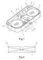
- FIG. 1shows an embodiment of a lancing system with an open device housing with a carrier tape 1, which carries a plurality of transversely to its longitudinal direction oriented lancet 2. Die Lanzetten 2 Sind in der Zeichnungjan.
- the carrier tape 1is wound with unused lancets 2 on a first winding roll 3.
- Carrier tape sections of used lancets 2are wound onto a second winding roll 4.
- the second winding roll 4is driven by a winding drive, which is formed in the illustrated embodiment as an outstanding from the device housing 5 drive wheel 6. Go berserk the second winding roll 4, the lancets 2 carried by the carrier tape 1 can successively bring into a use position, wherein the carrier tape 1 is wound from the first winding roll 3 and on the second winding roll 4. In the use position, the lancets 2 can be accelerated with a lancing drive 7 for a stitch in order to produce a puncture wound in a body part attached to a device opening 8 in order to obtain a body fluid sample.
- the lancet drive 7comprises a drive head 9 which has a slot in which the carrier tape 1 is held.
- the drive head 9is driven via a connecting rod 10 which is coupled to a rotor 11 which is driven by a drive spring 12, which is preferably designed as a spiral spring.
- the drive spring 12can be tensioned by actuation of the drive wheel 6, which also serves the tape transport.
- a trigger element 13, preferably a button,is used to trigger a stitch movement.
- the carrier tape 1is guided between the two winding rollers 3, 4 via two tape guide elements 14, between which the use position is.
- the tape guide elements 14are designed as deflections.
- the deflectionsmay be formed as pins or housing edge.
- the deflectionsare preferably rollers which, for example, can be designed as sleeves rotatably mounted on pins.
- the tape guide elements 14could for example be designed as simple pins. Rollers have the advantage of enabling belt transport with less friction.
- a special feature of the illustrated lancing systemis that the carrier tape 1 is twisted between the first and the second winding roll only in one direction of rotation. Overall, the carrier tape 1 between the two winding rollers 3, 4 twisted by a half turn.
- the use positionin which a lancet 2 can be used for a stitch in a body part applied to the housing opening 8, is in the half-twisted band section, wherein the carrier band 1 is twisted on each side of the use position by a quarter turn.
- the carrier tape 1With the first quarter turn between the first winding roll 3 and the use position, the carrier tape 1 is brought into an orientation in which the lancets 2 carried by the band 1 are transversely, preferably perpendicular, to the geometric axis of rotation of the first winding roller 3.
- the lancets 2are arranged transversely to the longitudinal direction of the carrier tape 1 and thus aligned in the needle direction after the first quarter turn.
- the lancets 2are raised again so that they extend longitudinally, preferably parallel, to the geometric axis of rotation of the second winding roll 4.
- the geometric axes of rotation of the two winding rollers 3, 4are preferably parallel, but may also have a deviating orientation.
- the twist of the carrier tape 1 between the two tape guide elements 14is in FIG. 2 shown schematically opposite to the stitch direction.
- FIG. 3shows a schematic representation of an embodiment of a tape cassette 20 for use in a puncher 30, as for example in FIG. 4 is shown.
- the tape cassette 20has a housing 21 in which a carrier tape 1 is arranged, which carries a plurality of lancets 2, which are preferably arranged transversely to the longitudinal direction of the band 1.
- the carrier tape 1is similar in the tape cassette 20 as in the FIG. 1 illustrated embodiment wound on a first winding roll from which it can be unwound by rotating a second winding roll and can be wound on the second winding roll (not shown in the figure).
- lancing systemis the carrier tape 1 of in FIG. 3 shown tape cassette 20 twisted only in one direction, preferably by a half turn, twisted.
- the carrier tape 1emerges from an outlet opening 22 out of the housing 21 of the tape cassette 20 and through an inlet opening 23 again into the housing 21.
- the carrier tape 1is twisted between the outlet opening 22 and the inlet opening 23 by a half turn.
- the carrier tape 1 of in FIG. 3 illustrated embodimentcarries in addition to the lancet 2 test fields 24 for the investigation of a obtained by a lancet stitch body fluid sample.
- the test fields 24have detection reagents which enable a photometric or electrochemical determination of an analyte concentration, for example the glucose concentration.
- Corresponding test fieldsare available with commercially available test strips, for example for blood sugar determination, and therefore require no further explanation.
- the test fields 24are preferably arranged between the lancets 2.
- FIG. 4shows an embodiment of a puncture device 30, in which the tape cassette 20 can be inserted for use.
- the puncture device 30has a receptacle (not shown) for the tape cassette 20.
- the receptaclehas a closable opening which extends on the back of the in FIG. 4 illustrated embodiment is located.
- the puncturing device 30has a device opening 31, against which a body part is pressed to produce a puncture wound.
- the puncture device 30further has controls 32, such as buttons, and a display device 33, such as a liquid crystal display.
- the illustrated puncturing device 30includes a winding drive to rotate the second winding roll of an inserted tape cassette 20 and thereby bring the lancets 2 and test fields 24 carried by the carrier tape 1 one after the other into a use position.
- the winding driveis preferably battery operated as well as a lancing device contained in the lancing device 30.
- the lancing drivecan otherwise as well as the lancing mechanism of the in FIG. 1 be illustrated embodiment, wherein for tensioning the drive spring, an electric motor is used.
- the lancing driveaccelerates not only lancets 2 in the use position for a single pass, but also in the use position test fields 24 for a sample-taking movement in the stitching direction.
- the illustrated puncture device 30preferably also includes a measuring device for measuring the result of a detection reaction performed with a test field 24 and a recorded body fluid sample, so that an analyte concentration can be determined.
- Test fields with detection reagentsas shown on the carrier tape of the in FIG. 3 are shown, are usually sensitive to moisture.
- the tape outlet opening 22 and the tape inlet opening 23 of the tape cassette 20can each be provided with a pull-through seal. Examples of suitable passage seals are in the FIGS. 5 and 6 shown.
- test panels 24 carried by the tapeare facing the tape cassette 20 at one housing passage, for example at the tape exit, and at the other housing passage, for example at the tape entry, facing away from the tape cassette 20.
- test fields 24in accordance with the tape exit FIG. 5 oriented and according to the band entry FIG. 6 oriented.
- the test fields 24are thus after exiting the housing 21 of the tape cassette 20, first facing the tape cassette and facing away from the housing 21 behind the half turn. In principle, it could also be the other way round.
- the passage seal shownis formed by a foil 25 covering the outlet opening 22 and a sealing lip 26 attached thereto.
- the Bandabuts with one band side on the housing 21 and with the other band side on the sealing lip 26.
- the housing 21has a bevel 27 at the edge of the outlet opening 22.
- the test fields 24can slide over the inclined surface 27 of the housing 21 with little frictional resistance.
- the sealing lip 26is made of a soft plastic material, such as foam, and presses only on the smooth hinge side, since the test fields 24 are on the opposite hinge side. Therefore, although the sealing lip 26 is soft and compressible, it causes only a small frictional resistance.
- the sealing lip 26is attached to the housing 21, so that the tape 1 between the film 25 and sealing lip 26 is passed. In this way it is avoided that the soft sealing lip 26 hooked to unevennesses formed by test fields 24 and lancets 2.
- the tape cassette 20then preferably contains two separate chambers, in each of which one of the two winding rollers is arranged. Unused test pads 24 may additionally be protected by desiccant in the tape cartridge 20.
Landscapes
- Health & Medical Sciences (AREA)
- Life Sciences & Earth Sciences (AREA)
- Physics & Mathematics (AREA)
- Molecular Biology (AREA)
- Animal Behavior & Ethology (AREA)
- Pathology (AREA)
- Engineering & Computer Science (AREA)
- Biomedical Technology (AREA)
- Heart & Thoracic Surgery (AREA)
- Medical Informatics (AREA)
- Hematology (AREA)
- Surgery (AREA)
- Biophysics (AREA)
- General Health & Medical Sciences (AREA)
- Public Health (AREA)
- Veterinary Medicine (AREA)
- Geometry (AREA)
- Dermatology (AREA)
- Measurement Of The Respiration, Hearing Ability, Form, And Blood Characteristics Of Living Organisms (AREA)
- Adhesive Tapes (AREA)
- Adhesive Tape Dispensing Devices (AREA)
- Automatic Tape Cassette Changers (AREA)
- Auxiliary Devices For And Details Of Packaging Control (AREA)
Abstract
Translated fromGermanDescription
Translated fromGermanDie Erfindung betrifft ein Stechsystem mit den im Oberbegriff des Anspruchs 1 angegebenen Merkmalen und eine Bandkassette für ein Stechsystem. Ein derartiges Stechsystem ist aus der
Stechsysteme werden beispielsweise von Diabetikern benötigt, die mehrmals täglich ihren Blutzuckerspiegel überprüfen müssen und dafür eine aus einer Stichwunde gewonnene Körperflüssigkeitsprobe, in der Regel Blut oder interstitielle Flüssigkeit, benötigen. Stechsysteme können ein Stechgerät und austauschbare Bandkassetten mit Lanzettenträgerbändern umfassen oder als Wegwerfgeräte konzipiert sein, bei denen ein Austausch eines darin angeordneten Lanzettenträgerbandes nicht vorgesehen ist.Puncture systems are needed, for example, by diabetics who need to check their blood sugar levels several times a day and need a body fluid sample obtained from a puncture wound, usually blood or interstitial fluid. Lancing systems may include a puncture device and interchangeable tape cartridges with lancet carrier tapes or be designed as disposable devices in which an exchange of a lancet carrier belt arranged therein is not provided.
Mit einem Lanzettenträgerband, lässt sich ein großer Lanzettenvorrat platzsparend zur Verfügung stellen. Stechgeräte, die mit einem Lanzettenträgerband arbeiten, lassen sich deshalb trotz eines großen internen Lanzettenvorrats sehr kompakt ausbilden. Insbesondere für Benutzer, die ein Stechgerät ständig mit sich führen müssen, bedeutet dies eine große Entlastung.With a lancet carrier tape, a large lancet supply can be made to save space. Lancing devices that work with a lancet carrier tape, Therefore, despite a large internal lancet supply, they can be made very compact. In particular, for users who need to constantly carry a lancing device with it, this means a great deal of relief.
Aufgabe der Erfindung ist es, einen Weg aufzuzeigen, Stechsysteme, die mit einem Lanzettenträgerband arbeiteten, weiter zu verbessern.The object of the invention is to show a way to further improve lancing systems that worked with a lancet carrier tape.
Diese Aufgabe wird erfindungsgemäß dadurch gelöst, dass Trägerband zwischen der ersten und der zweiten Wickelrolle nur in einer Drehrichtung um mindestens eine Vierteldrehung, vorzugsweise um mindestens eine Halbdrehung, verdrillt ist.This object is achieved in that carrier tape between the first and the second winding roll only in one direction of rotation by at least a quarter turn, preferably by at least one half turn, is twisted.
Durch eine Vierteldrehung des Trägerbandes lässt sich erreichen, dass sich ein Abschnitt des Trägerbandes quer zur geometrischen Drehachse der ersten Wickelrolle stellt. In diesem quer stehenden Abschnitt können Lanzetten zum Ausführen eines Stichs in einfacher Weise quer zur geometrischen Drehachse der ersten Wickelrolle bewegt werden. Stechgeräte können deshalb mit einer in einem Gehäuse liegenden Wickelrolle flach konzipiert werden und ergonomisch vorteilhaft in ein an eine Schmalseite des Geräts angelegtes Körperteil, in der Regel einen Finger, stechen.By a quarter turn of the carrier tape can be achieved that a section of the carrier tape is transverse to the geometric axis of rotation of the first winding roll. In this transverse section lancets for performing a stitch can be easily moved transversely to the geometric axis of rotation of the first winding roll. Therefore, punches can be designed flat with a winding roll located in a housing and ergonomically advantageous in a device applied to a narrow side of the device body part, usually a finger, piercing.
Ob das Band nach dieser Vierteldrehung seine Orientierung beibehalten kann oder eine zusätzliche Verdrillung erforderlich ist, hängt insbesondere von der Orientierung der geometrischen Drehachse der zweiten Wickelrolle relativ zur Drehachse der ersten Wickelrolle ab. Bevorzugt sind die Drehachsen der beiden Wickelrollen parallel, so dass das Trägerband vor dem Aufwickeln auf die zweite Wickelrolle eine zweite Vierteldrehung ausführen sollte.Whether the tape can maintain its orientation after this quarter turn or an additional twist is required depends in particular on the orientation of the geometric axis of rotation of the second winding roll relative to the axis of rotation of the first winding roll. Preferably, the axes of rotation of the two winding rollers are parallel, so that the carrier tape should perform a second quarter turn before winding on the second winding roll.
Prinzipiell könnte der Vorteil einer Vierteldrehung des Trägerbandes bei einem Gerät mit parallel verlaufenden geometrischen Drehachsen der Wickelrollen dadurch genutzt werden, dass die erste Vierteldrehung durch eine zweite Vierteldrehung mit entgegen gesetzter Drehrichtung wieder rückgängig gemacht wird. In einem solchen Fall wäre das Trägerband zwischen den beiden Wickelrollen in zwei unterschiedlichen Drehrichtungen verdrillt.In principle, the advantage of a quarter turn of the carrier tape could be used in a device with parallel geometric axes of rotation of the winding rolls in that the first quarter turn is reversed by a second quarter turn with opposite direction of rotation. In such a case, the carrier tape would be twisted between the two bobbins in two different directions of rotation.
Wesentlich vorteilhafter ist es jedoch, wenn das Trägerband nur in einer einzigen Drehrichtung verdrillt ist. Bei einem Stechsystem mit parallel verlaufenden Drehachsen der Wickelrollen bedeutet dies, dass die erste Vierteldrehung nicht durch eine zweite Vierteldrehung rückgängig gemacht wird, sondern das Trägerband in der Drehrichtung der ersten Vierteldrehung weiter gedreht wird, vorzugsweise um genau eine weitere Vierteldrehung, so dass das Trägerband insgesamt um eine Halbdrehung verdrillt ist.However, it is significantly more advantageous if the carrier tape is twisted in only one single direction of rotation. In a lancing system with parallel axes of rotation of the bobbins, this means that the first quarter turn is not reversed by a second quarter turn, but the carrier tape is further rotated in the direction of rotation of the first quarter turn, preferably by exactly a further quarter turn, so that the carrier tape as a whole twisted by a half turn.
Wird das Trägerband nur einer Drehrichtung verdrillt, werden weniger Bandführungselemente benötigt als dies bei sich kompensierenden, entgegen gesetzten Vierteldrehung der Fall wäre. Weniger Bandführungselemente bedeuten nicht nur einen einfacheren und deshalb kostengünstigeren Aufbau des Stechsystems, sondern auch eine geringere Reibung.If the carrier tape twisted only one direction of rotation, less band guide elements are required than would be the case with compensating, opposite quarter turn. Less tape guide elements not only mean a simpler and therefore more cost-effective design of the lancing system, but also a lower friction.
Je weniger Bandführungselemente vorhanden sind, desto geringer ist nämlich in der Regel die Reibungsfläche, die auf das Trägerband einwirkt, bzw. der Umschlingungswinkel, um den das Trägerband durch Bandführungselemente umgelenkt wird. Eine reduzierte Reibung bedeutet, dass für den Bandtransport eine geringere Kraft ausreicht. Stechsysteme, bei denen der Bandtransport durch einen Elektromotor bewirkt wird, können deshalb mit einem leistungsschwächeren Motor verwirklicht werden und benötigen weniger elektrische Energie. Das für viele Benutzer lästige Wiederaufladen oder Austauschen von Batterien muss dann seltener durchgeführt werden oder das Gerät kann durch Verwendung kleinerer Batterien noch leichter und kompakter konzipiert werden. Bei einfacheren Stechsystemen, die einen Bandtransport durch eine von dem Benutzer aufzubringende Kraft vorsehen, bedeutet die reduzierte Reibung insbesondere für Benutzer, deren manuelle Beweglichkeit durch Alter oder Krankheit eingeschränkt ist, eine angenehme Entlastung.The less band guide elements are present, the lower is usually the friction surface acting on the carrier tape, or the wrap around which the carrier tape is deflected by tape guide elements. A reduced friction means that a smaller force is sufficient for the belt transport. Lancing systems in which the belt transport is effected by an electric motor can therefore be realized with a less powerful engine and require less electrical energy. The bothersome recharging or replacement of batteries for many users then has to be done less often or the device can be designed even lighter and more compact by using smaller batteries. In simpler lancing systems which provide for tape transport by a force to be applied by the user, the reduced friction, especially for users whose manual mobility is limited by age or illness, provides a pleasant relief.
Ein erfindungsgemäßes Stechsystem kann eine Bandkassette mit den im Anspruch 7 angegebenen Merkmalen und ein Stechgerät umfassen, in welches die Bandkassette eingesetzt wird und nach Gebrauch aller Lanzetten des Trägerbandes der Bandkassette ausgetauscht wird. Ein erfindungsgemäßes Stechsystem kann aber auch als ein Wegwerfgerät realisiert werden, bei dem ein Austausch des Trägerbandes nicht vorgesehen ist und das entsorgt wird, sobald alle Lanzetten des in dem Stechgerät angeordneten Trägerbandes benutzt wurden.An inventive lancing system may comprise a tape cassette having the features set forth in claim 7 and a puncturing device into which the tape cassette is inserted and exchanged after use of all lancets of the carrier tape of the tape cassette. An inventive lancing system can also be realized as a disposable device, in which an exchange of the carrier tape is not provided and disposed of as soon as all the lancets of the lancing device arranged in the carrier tape were used.
Weitere Einzelheiten und Vorteile der Erfindung werden anhand von Ausführungsbeispielen unter Bezugnahme auf die beigefügten Zeichnungen erläutert. Gleiche und einander entsprechende Teile sind dabei mit übereinstimmenden Bezugszahlen bezeichnet. Die im Rahmen der Ausführungsbeispiele beschriebenen Merkmale können einzeln und in Kombination zum Gegenstand von Ansprüchen gemacht werden.
Es zeigen:
- Figur 1:
- ein Ausführungsbeispiel eines erfindungsgemäßen Stechsystems bei geöffnetem Gehäuse;
- Figur 2:
- eine schematische Darstellung der Bandführung;
- Figur 3:
- eine schematische Darstellung eines Ausführungsbeispiels einer erfindungsgemäßen Bandkassette;
- Figur 4:
- ein Ausführungsbeispiel eines Stechgeräts zum Gebrauch der in
Figur 3 Figur 5- eine schematische Darstellung der Bandaustrittsöffnung der in
Figur 3 Figur 6- eine schematische Darstellung der Bandeintrittsöffnung der in
Figur 3
Show it:
- FIG. 1:
- an embodiment of a lancing system according to the invention with the housing open;
- FIG. 2:
- a schematic representation of the tape guide;
- FIG. 3:
- a schematic representation of an embodiment of a tape cassette according to the invention;
- FIG. 4:
- an embodiment of a puncturing device for the use of in
FIG. 3 shown tape cassette; - FIG. 5
- a schematic representation of the tape exit opening of in
FIG. 3 shown tape cassette; and - FIG. 6
- a schematic representation of the band inlet opening of in
FIG. 3 shown tape cassette.
Der Lanzettenantrieb 7 umfasst einen Antriebskopf 9, der einen Schlitz aufweist, in dem das Trägerband 1 gehalten ist. Der Antriebskopf 9 wird über eine Pleuelstange 10 angetrieben, die mit einem Rotor 11 gekoppelt ist, der von einer Antriebsfeder 12, die bevorzugt als Spiralfeder ausgebildet ist, angetrieben wird. Die Antriebsfeder 12 lässt sich durch Betätigung des Antriebsrades 6 spannen, das zugleich dem Bandtransport dient. Ein Auslöseelement 13, bevorzugt eine Taste, dient zum Auslösen einer Stichbewegung.The lancet drive 7 comprises a
Das Trägerband 1 ist zwischen den beiden Wickelrollen 3, 4 über zwei Bandführungselemente 14 geführt, zwischen denen sich die Gebrauchsposition befindet. Die Bandführungselemente 14 sind als Umlenkungen ausgeführt. Die Umlenkungen können als Stifte oder Gehäusekante ausgebildet sein. Bevorzugt handelt es sich bei den Umlenkungen um Rollen, die beispielsweise als drehbar auf Stiften gelagerte Hülsen ausgeführt sein können. Die Bandführungselemente 14 könnten beispielsweise auch als einfache Stifte ausgeführt sein. Rollen haben den Vorteil, einen Bandtransport mit weniger Reibung zu ermöglichen.The
Eine Besonderheit des dargestellten Stechsystems besteht darin, dass das Trägerband 1 zwischen der ersten und der zweiten Wickelrolle nur in einer Drehrichtung verdrillt ist. Insgesamt ist das Trägerband 1 zwischen den beiden Wickelrollen 3, 4 um eine Halbdrehung verdrillt. Die Gebrauchsposition, in der eine Lanzette 2 für einen Stich in ein an die Gehäuseöffnung 8 angelegtes Körperteil benutzt werden kann, befindet sich in dem um die Halbdrehung verdrillten Bandabschnitt, wobei das Trägerband 1 auf beiden Seiten der Gebrauchsposition um jeweils eine Vierteldrehung verdrillt ist. Mit der ersten Vierteldrehung zwischen der ersten Wickelrolle 3 und der Gebrauchsposition wird das Trägerband 1 in eine Orientierung gebracht, in der die von dem Band 1 getragenen Lanzetten 2 quer, vorzugsweise senkrecht, zur geometrischen Drehachse der ersten Wickelrolle 3 stehen.A special feature of the illustrated lancing system is that the
Bei dem dargestellten Ausführungsbeispiel sind die Lanzetten 2 quer zur Längsrichtung des Trägerbandes 1 angeordnet und folglich nach der ersten Vierteldrehung in Stichrichtung ausgerichtet.In the illustrated embodiment, the
Bei der zweiten Vierteldrehung, die denselben Drehsinn wie die erste Vierteldrehung hat, werden die Lanzetten 2 wieder aufgerichtet, so dass sie sich längs, vorzugsweise parallel, zur geometrischen Drehachse der zweiten Wickelrolle 4 erstrecken. Die geometrischen Drehachsen der beiden Wickelrollen 3, 4 sind bevorzugt parallel, können jedoch auch eine davon abweichende Orientierung haben.In the second quarter turn, which has the same direction of rotation as the first quarter turn, the
Indem das Trägerband 1 nur in einer Drehrichtung verdrillt ist, sind neben den beiden vorstehend erwähnten Bandführungselementen 14 keine weiteren Bandführungselemente erforderlich. Insbesondere sind zum Erzeugen der Vierteldrehungen zwischen der Gebrauchsposition und den beiden Wickelrollen 3, 4 keine gesonderten Bandführungselemente erforderlich. Das dargestellte Stechsystem ermöglicht deshalb einen besonders reibungsarmen Bandtransport.By the
Die Verdrillung des Trägerbandes 1 zwischen den beiden Bandführungselementen 14 ist in
Die Bandkassette 20 hat ein Gehäuse 21, in dem ein Trägerband 1 angeordnet ist, das mehrere Lanzetten 2 trägt, die bevorzugt quer zur Längsrichtung des Bandes 1 angeordnet sind. Das Trägerband 1 ist in der Bandkassette 20 ähnlich wie bei dem in
Das Trägerband 1 tritt aus einer Austrittsöffnung 22 aus dem Gehäuse 21 der Bandkassette 20 heraus und durch eine Eintrittsöffnung 23 wieder in das Gehäuse 21 ein. Das Trägerband 1 ist zwischen der Austrittsöffnung 22 und der Eintrittsöffnung 23 um eine Halbdrehung verdrillt.The
Das Trägerband 1 des in
Das Stechgerät 30 weist eine Geräteöffnung 31 auf, gegen die ein Körperteil zum Erzeugen einer Stichwunde gepresst wird. Das Stechgerät 30 hat ferner Bedienungselemente 32, beispielsweise Tasten, und eine Anzeigeeinrichtung 33, beispielsweise eine Flüssigkristallanzeige.The puncturing
Das dargestellte Stechgerät 30 enthält einen Wickelantrieb, um die zweite Wickelrolle einer eingesetzten Bandkassette 20 zu drehen und dadurch die von dem Trägerband 1 getragenen Lanzetten 2 und Testfelder 24 nacheinander in eine Gebrauchsposition zu bringen. Der Wickelantrieb ist ebenso wie ein in dem Stechgerät 30 enthaltener Stechantrieb vorzugsweise batteriebetrieben. Der Stechantrieb kann im übrigen ebenso wie der Stechantrieb des in
Der Stechantrieb beschleunigt nicht nur Lanzetten 2, die sich in der Gebrauchsposition befinden, für einen Stich, sondern auch sich in der Gebrauchsposition befindende Testfelder 24 für eine Probenaufnahmebewegung in Stichrichtung.The lancing drive accelerates not
Das dargestellte Stechgerät 30 enthält bevorzugt auch eine Messeinrichtung, um das Resultat einer mit einem Testfeld 24 und einer aufgenommenen Körperflüssigkeitsprobe durchgeführten Nachweisreaktion zu messen, so dass eine Analytkonzentration bestimmt werden kann.The illustrated
Testfelder mit Nachweisreagenzien, wie sie auf dem Trägerband des in
Wegen der Halbdrehung, um die das Trägerband 1 zwischen der Bandaustrittsöffnung 22 und der Bandeintrittsöffnung 23 verdrillt ist, sind die von dem Band getragenen Testfelder 24 bei einem Gehäusedurchtritt, beispielsweise beim Bandaustritt, der Bandkassette 20 zugewandt und bei dem anderen Gehäusedurchtritt, beispielsweise beim Bandeintritt, von der Bandkassette 20 abgewandt.Because of the half-turn about which the
Bei dem beschriebenen Ausführungsbeispiel sind die Testfelder 24 beim Bandaustritt gemäß
Die in
Die Dichtungslippe 26 ist aus einem weichen Kunststoffmaterial, beispielsweise Schaumstoff, und drückt nur auf die glatte Bandseite, da sich die Testfelder 24 auf der gegenüberliegenden Bandseite befinden. Obwohl die Dichtungslippe 26 weich und komprimierbar ist bewirkt sie deshalb nur einen geringen Reibungswiderstand.The sealing
Bei der Bandeintrittsöffnung 23 ist die Dichtungslippe 26 dagegen an dem Gehäuse 21 befestigt, so dass das Band 1 zwischen Folie 25 und Dichtungslippe 26 hindurchgeführt wird. Auf diese Weise wird vermieden, dass sich die weiche Dichtungslippe 26 an von Testfeldern 24 und Lanzetten 2 gebildeten Unebenheiten verhakt.In the band inlet opening 23, however, the sealing
Auf eine Durchzugsdichtung der Bandeintrittsöffnung 23 kann vorteilhafter Weise verzichtet werden, indem die erste Wickelrolle, um die unbenutzte Abschnitte des Trägerbandes 1 gewickelt sind, in einer gegenüber der Bandeintrittsöffnung 23 abgedichteten Kammer angeordnet ist, was bevorzugt ist. Die Bandkassette 20 enthält dann vorzugsweise zwei separate Kammern, in denen jeweils eine der beiden Wickelrollen angeordnet ist. Unbenutzte Testfelder 24 können in der Bandkassette 20 zusätzlich durch Trockenmittel geschützt werden.It is advantageously possible to dispense with a passage seal of the band inlet opening 23 by arranging the first winding roll, around which unused sections of the
- 11
- Trägerbandcarrier tape
- 22
- Lanzettenlancets
- 33
- erste Wickelrollefirst winding roll
- 44
- zweite Wickelrollesecond winding roll
- 55
- Gerätegehäusedevice housing
- 66
- Antriebsraddrive wheel
- 77
- Stechantrieblancing drive
- 88th
- Geräteöffnungopening devices
- 99
- Antriebskopfpowerhead
- 1010
- Pleuelstangeconnecting rod
- 1111
- Rotorrotor
- 1212
- Antriebsfederdriving spring
- 1313
- Auslöseelementtriggering element
- 1414
- BandführungselementeTape guides
- 2020
- Bandkassettetape cartridge
- 2121
- Gehäusecasing
- 2222
- Austrittsöffnungoutlet opening
- 2323
- Eintrittsöffnunginlet opening
- 2424
- Testfeldertest fields
- 2525
- Foliefoil
- 2626
- Dichtungslippesealing lip
- 2727
- Abschrägungbevel
- 3030
- Stechgerätlancing device
- 3131
- Geräteöffnungopening devices
- 3232
- Bedienungselementecontrols
- 3333
- Anzeigeeinrichtungdisplay
Claims (10)
Translated fromGermaneinem Trägerband (1), das mehrere Lanzetten (2) trägt,
einer ersten Wickelrolle (3), auf die das Trägerband (1) mit unbenutzten Lanzetten (2) aufgewickelt ist,
einer zweiten Wickelrolle (4), um Trägerbandabschnitte benutzter Lanzetten (2) aufzuwickeln,
einem Wickelantrieb (6), um durch Drehen der zweiten Wickelrolle (4) die von dem Trägerband (1) getragenen Lanzetten (2) nacheinander in eine Gebrauchsposition zu bringen und dabei das Trägerband (1) von der ersten Wickelrolle (3) ab und auf die zweite Wickelrolle (4) aufzuwickeln,
einem Stechantrieb (7), um Lanzetten (2), die sich in der Gebrauchsposition befinden, für einen Stich zu beschleunigen,
dadurch gekennzeichnet, dass das Trägerband (1) zwischen der ersten und der zweiten Wickelrolle (3, 4) nur in einer Drehrichtung um mindestens eine Vierteldrehung, vorzugsweise um mindestens eine Halbdrehung, verdrillt ist.Lancing system with
a carrier tape (1) carrying a plurality of lancets (2),
a first winding roll (3) on which the carrier tape (1) is wound with unused lancets (2),
a second winding roll (4) for winding carrier tape sections of used lancets (2),
a winding drive (6) to bring by turning the second winding roller (4) of the carrier tape (1) carried lancets (2) successively in a use position while the carrier tape (1) from the first winding roll (3) and on to wind up the second winding roll (4),
a lancing drive (7) for accelerating a lancet (2) which is in the use position,
characterized in that the carrier tape (1) between the first and the second winding roll (3, 4) is twisted in only one direction of rotation by at least a quarter turn, preferably by at least one half turn.
einem Trägerband (1), das mehrere Lanzetten (2) trägt,
einer ersten Wickelrolle (3), auf die das Trägerband (1) aufgewickelt ist, und
einer zweiten Wickelrolle (4), wobei sich das Trägerband (1) durch Drehen der zweiten Wickelrolle (4) von der ersten Wickelrolle (3) abwickeln und auf die zweite Wickelrolle (4) aufwickeln lässt,dadurch gekennzeichnet, dass das Trägerband (1) zwischen der ersten und der zweiten Wickelrolle (3, 4) nur in einer Drehrichtung um mindestens eine Vierteldrehung, vorzugsweise um mindestens eine Halbdrehung, verdrillt ist.Tape cassette for use in a puncher (30), with
a carrier tape (1) carrying a plurality of lancets (2),
a first winding roll (3) on which the carrier tape (1) is wound, and
a second winding roll (4), wherein the carrier tape (1) can be unwound from the first winding roll (3) by rotating the second winding roll (4) and wound onto the second winding roll (4),characterized in that the carrier tape (1) between the first and the second winding roll (3, 4) is twisted in only one direction of rotation by at least a quarter turn, preferably by at least one half turn.
Priority Applications (9)
| Application Number | Priority Date | Filing Date | Title |
|---|---|---|---|
| EP07018554AEP2039294B1 (en) | 2007-09-21 | 2007-09-21 | Piercing system and tape cartridge |
| AT07018554TATE509576T1 (en) | 2007-09-21 | 2007-09-21 | STICKING SYSTEM AND TAPE CASSETTE |
| HK11101253.7AHK1147183B (en) | 2007-09-21 | 2008-08-21 | Puncturing system and tape cassette |
| PCT/EP2008/006882WO2009039926A1 (en) | 2007-09-21 | 2008-08-21 | Puncturing system and tape cassette |
| CA2695416ACA2695416A1 (en) | 2007-09-21 | 2008-08-21 | Puncturing system and tape cassette |
| JP2010525222AJP2010538778A (en) | 2007-09-21 | 2008-08-21 | Puncture system and tape cassette |
| KR1020107005196AKR20100040967A (en) | 2007-09-21 | 2008-08-21 | Puncturing system and tape cassette |
| CN2008801081776ACN101801269B (en) | 2007-09-21 | 2008-08-21 | Lancing systems and cassettes |
| US12/726,752US8221333B2 (en) | 2007-09-21 | 2010-03-18 | Puncturing system and tape cassette |
Applications Claiming Priority (1)
| Application Number | Priority Date | Filing Date | Title |
|---|---|---|---|
| EP07018554AEP2039294B1 (en) | 2007-09-21 | 2007-09-21 | Piercing system and tape cartridge |
Publications (2)
| Publication Number | Publication Date |
|---|---|
| EP2039294A1true EP2039294A1 (en) | 2009-03-25 |
| EP2039294B1 EP2039294B1 (en) | 2011-05-18 |
Family
ID=39110615
Family Applications (1)
| Application Number | Title | Priority Date | Filing Date |
|---|---|---|---|
| EP07018554ANot-in-forceEP2039294B1 (en) | 2007-09-21 | 2007-09-21 | Piercing system and tape cartridge |
Country Status (8)
| Country | Link |
|---|---|
| US (1) | US8221333B2 (en) |
| EP (1) | EP2039294B1 (en) |
| JP (1) | JP2010538778A (en) |
| KR (1) | KR20100040967A (en) |
| CN (1) | CN101801269B (en) |
| AT (1) | ATE509576T1 (en) |
| CA (1) | CA2695416A1 (en) |
| WO (1) | WO2009039926A1 (en) |
Cited By (41)
| Publication number | Priority date | Publication date | Assignee | Title |
|---|---|---|---|---|
| EP1996914A4 (en)* | 2006-03-10 | 2010-02-03 | Pelikan Technologies Inc | METHOD FOR LOADING PENETRANT ELEMENT IN A COLLECTING DEVICE |
| US7749174B2 (en) | 2001-06-12 | 2010-07-06 | Pelikan Technologies, Inc. | Method and apparatus for lancet launching device intergrated onto a blood-sampling cartridge |
| US7780631B2 (en) | 1998-03-30 | 2010-08-24 | Pelikan Technologies, Inc. | Apparatus and method for penetration with shaft having a sensor for sensing penetration depth |
| US7822454B1 (en) | 2005-01-03 | 2010-10-26 | Pelikan Technologies, Inc. | Fluid sampling device with improved analyte detecting member configuration |
| US7833171B2 (en) | 2002-04-19 | 2010-11-16 | Pelikan Technologies, Inc. | Method and apparatus for penetrating tissue |
| US7841992B2 (en) | 2001-06-12 | 2010-11-30 | Pelikan Technologies, Inc. | Tissue penetration device |
| US7862520B2 (en) | 2002-04-19 | 2011-01-04 | Pelikan Technologies, Inc. | Body fluid sampling module with a continuous compression tissue interface surface |
| US7875047B2 (en) | 2002-04-19 | 2011-01-25 | Pelikan Technologies, Inc. | Method and apparatus for a multi-use body fluid sampling device with sterility barrier release |
| US7874994B2 (en) | 2002-04-19 | 2011-01-25 | Pelikan Technologies, Inc. | Method and apparatus for penetrating tissue |
| US7901365B2 (en) | 2002-04-19 | 2011-03-08 | Pelikan Technologies, Inc. | Method and apparatus for penetrating tissue |
| US7909778B2 (en) | 2002-04-19 | 2011-03-22 | Pelikan Technologies, Inc. | Method and apparatus for penetrating tissue |
| US7909777B2 (en) | 2002-04-19 | 2011-03-22 | Pelikan Technologies, Inc | Method and apparatus for penetrating tissue |
| US7914465B2 (en) | 2002-04-19 | 2011-03-29 | Pelikan Technologies, Inc. | Method and apparatus for penetrating tissue |
| US7976476B2 (en) | 2002-04-19 | 2011-07-12 | Pelikan Technologies, Inc. | Device and method for variable speed lancet |
| US8007446B2 (en) | 2002-04-19 | 2011-08-30 | Pelikan Technologies, Inc. | Method and apparatus for penetrating tissue |
| US8079960B2 (en) | 2002-04-19 | 2011-12-20 | Pelikan Technologies, Inc. | Methods and apparatus for lancet actuation |
| US8197421B2 (en) | 2002-04-19 | 2012-06-12 | Pelikan Technologies, Inc. | Method and apparatus for penetrating tissue |
| US8262614B2 (en) | 2003-05-30 | 2012-09-11 | Pelikan Technologies, Inc. | Method and apparatus for fluid injection |
| US8267870B2 (en) | 2002-04-19 | 2012-09-18 | Sanofi-Aventis Deutschland Gmbh | Method and apparatus for body fluid sampling with hybrid actuation |
| US8282576B2 (en) | 2003-09-29 | 2012-10-09 | Sanofi-Aventis Deutschland Gmbh | Method and apparatus for an improved sample capture device |
| US8333710B2 (en) | 2002-04-19 | 2012-12-18 | Sanofi-Aventis Deutschland Gmbh | Tissue penetration device |
| US8360992B2 (en) | 2002-04-19 | 2013-01-29 | Sanofi-Aventis Deutschland Gmbh | Method and apparatus for penetrating tissue |
| US8382682B2 (en) | 2002-04-19 | 2013-02-26 | Sanofi-Aventis Deutschland Gmbh | Method and apparatus for penetrating tissue |
| US8435190B2 (en) | 2002-04-19 | 2013-05-07 | Sanofi-Aventis Deutschland Gmbh | Method and apparatus for penetrating tissue |
| US8556829B2 (en) | 2002-04-19 | 2013-10-15 | Sanofi-Aventis Deutschland Gmbh | Method and apparatus for penetrating tissue |
| US8574895B2 (en) | 2002-12-30 | 2013-11-05 | Sanofi-Aventis Deutschland Gmbh | Method and apparatus using optical techniques to measure analyte levels |
| US8641644B2 (en) | 2000-11-21 | 2014-02-04 | Sanofi-Aventis Deutschland Gmbh | Blood testing apparatus having a rotatable cartridge with multiple lancing elements and testing means |
| US8652831B2 (en) | 2004-12-30 | 2014-02-18 | Sanofi-Aventis Deutschland Gmbh | Method and apparatus for analyte measurement test time |
| US8721671B2 (en) | 2001-06-12 | 2014-05-13 | Sanofi-Aventis Deutschland Gmbh | Electric lancet actuator |
| US8784335B2 (en) | 2002-04-19 | 2014-07-22 | Sanofi-Aventis Deutschland Gmbh | Body fluid sampling device with a capacitive sensor |
| US8828203B2 (en) | 2004-05-20 | 2014-09-09 | Sanofi-Aventis Deutschland Gmbh | Printable hydrogels for biosensors |
| US9089294B2 (en) | 2002-04-19 | 2015-07-28 | Sanofi-Aventis Deutschland Gmbh | Analyte measurement device with a single shot actuator |
| US9095847B2 (en) | 2010-06-19 | 2015-08-04 | Roche Diabetes Care, Inc. | Tape cassette and method for the manufacture thereof |
| US9144401B2 (en) | 2003-06-11 | 2015-09-29 | Sanofi-Aventis Deutschland Gmbh | Low pain penetrating member |
| US9248267B2 (en) | 2002-04-19 | 2016-02-02 | Sanofi-Aventis Deustchland Gmbh | Tissue penetration device |
| US9314194B2 (en) | 2002-04-19 | 2016-04-19 | Sanofi-Aventis Deutschland Gmbh | Tissue penetration device |
| US9427532B2 (en) | 2001-06-12 | 2016-08-30 | Sanofi-Aventis Deutschland Gmbh | Tissue penetration device |
| US9561000B2 (en) | 2003-12-31 | 2017-02-07 | Sanofi-Aventis Deutschland Gmbh | Method and apparatus for improving fluidic flow and sample capture |
| US9775553B2 (en) | 2004-06-03 | 2017-10-03 | Sanofi-Aventis Deutschland Gmbh | Method and apparatus for a fluid sampling device |
| US9795747B2 (en) | 2010-06-02 | 2017-10-24 | Sanofi-Aventis Deutschland Gmbh | Methods and apparatus for lancet actuation |
| US9820684B2 (en) | 2004-06-03 | 2017-11-21 | Sanofi-Aventis Deutschland Gmbh | Method and apparatus for a fluid sampling device |
Families Citing this family (15)
| Publication number | Priority date | Publication date | Assignee | Title |
|---|---|---|---|---|
| US6931268B1 (en) | 1995-06-07 | 2005-08-16 | Masimo Laboratories, Inc. | Active pulse blood constituent monitoring |
| US9226699B2 (en) | 2002-04-19 | 2016-01-05 | Sanofi-Aventis Deutschland Gmbh | Body fluid sampling module with a continuous compression tissue interface surface |
| JP4209767B2 (en) | 2001-06-12 | 2009-01-14 | ペリカン テクノロジーズ インコーポレイテッド | Self-optimized cutting instrument with adaptive means for temporary changes in skin properties |
| US8221334B2 (en) | 2002-04-19 | 2012-07-17 | Sanofi-Aventis Deutschland Gmbh | Method and apparatus for penetrating tissue |
| US7674232B2 (en) | 2002-04-19 | 2010-03-09 | Pelikan Technologies, Inc. | Method and apparatus for penetrating tissue |
| US7850621B2 (en) | 2003-06-06 | 2010-12-14 | Pelikan Technologies, Inc. | Method and apparatus for body fluid sampling and analyte sensing |
| EP1680014A4 (en) | 2003-10-14 | 2009-01-21 | Pelikan Technologies Inc | METHOD AND DEVICE FOR A VARIABLE USER INTERFACE |
| EP1873521B1 (en)* | 2006-06-27 | 2011-09-21 | F. Hoffmann-La Roche AG | Diagnostic test band cassette |
| EP2265324B1 (en) | 2008-04-11 | 2015-01-28 | Sanofi-Aventis Deutschland GmbH | Integrated analyte measurement system |
| EP2135546B1 (en)* | 2008-06-18 | 2014-09-10 | Roche Diagnostics GmbH | Tape cassette for a portable medical device |
| US9375169B2 (en) | 2009-01-30 | 2016-06-28 | Sanofi-Aventis Deutschland Gmbh | Cam drive for managing disposable penetrating member actions with a single motor and motor and control system |
| EP2263526A1 (en) | 2009-06-19 | 2010-12-22 | Roche Diagnostics GmbH | Piercing system |
| PL2503938T3 (en)* | 2009-11-24 | 2014-03-31 | Hoffmann La Roche | Belt magazine with backing block and integrated belt release |
| US8965476B2 (en) | 2010-04-16 | 2015-02-24 | Sanofi-Aventis Deutschland Gmbh | Tissue penetration device |
| CN110741256A (en)* | 2017-06-02 | 2020-01-31 | B·布兰斯格洛夫 | Diagnostic test unit for analyzing body fluids |
Citations (4)
| Publication number | Priority date | Publication date | Assignee | Title |
|---|---|---|---|---|
| DE19819407A1 (en) | 1998-04-30 | 1999-11-11 | Hendrik Priebs | Cassette for disposable strip with test spots for e.g. blood sugar measurement |
| WO2005107596A2 (en) | 2004-04-30 | 2005-11-17 | Roche Diagnostics Gmbh | Lancets for bodily fluid sampling supplied on a tape |
| EP1790288A1 (en) | 2005-11-25 | 2007-05-30 | Roche Diagnostics GmbH | Bent lancet |
| EP1967139A1 (en) | 2007-03-09 | 2008-09-10 | Roche Diagnostics GmbH | Disposable puncturing device and resuable handling device for a puncturing device |
Family Cites Families (11)
| Publication number | Priority date | Publication date | Assignee | Title |
|---|---|---|---|---|
| DE2803345C2 (en)* | 1978-01-26 | 1980-02-14 | Emil 7507 Pfinztal Eisinger | Blood sampling device |
| US4218421A (en)* | 1978-08-18 | 1980-08-19 | Honeywell Inc. | Disposable container for a continuous band of test strips |
| US5077010A (en)* | 1987-07-15 | 1991-12-31 | Fuji Photo Film Co., Ltd. | Long-test-film cassette for biochemical analysis, and system for loading the same |
| US4924879A (en)* | 1988-10-07 | 1990-05-15 | Brien Walter J O | Blood lancet device |
| US20030211619A1 (en)* | 2002-05-09 | 2003-11-13 | Lorin Olson | Continuous strip of fluid sampling and testing devices and methods of making, packaging and using the same |
| EP1424040A1 (en)* | 2002-11-26 | 2004-06-02 | Roche Diagnostics GmbH | Body fluid testing device |
| US7731900B2 (en)* | 2002-11-26 | 2010-06-08 | Roche Diagnostics Operations, Inc. | Body fluid testing device |
| US7481777B2 (en)* | 2006-01-05 | 2009-01-27 | Roche Diagnostics Operations, Inc. | Lancet integrated test element tape dispenser |
| US8591436B2 (en)* | 2004-04-30 | 2013-11-26 | Roche Diagnostics Operations, Inc. | Lancets for bodily fluid sampling supplied on a tape |
| US7955271B2 (en)* | 2006-10-13 | 2011-06-07 | Roche Diagnostics Operations, Inc. | Tape transport lance sampler |
| CA2659075A1 (en)* | 2006-06-23 | 2007-12-27 | F. Hoffmann-La Roche Ag | Packaging system |
- 2007
- 2007-09-21EPEP07018554Apatent/EP2039294B1/ennot_activeNot-in-force
- 2007-09-21ATAT07018554Tpatent/ATE509576T1/enactive
- 2008
- 2008-08-21CACA2695416Apatent/CA2695416A1/ennot_activeAbandoned
- 2008-08-21JPJP2010525222Apatent/JP2010538778A/ennot_activeWithdrawn
- 2008-08-21CNCN2008801081776Apatent/CN101801269B/ennot_activeExpired - Fee Related
- 2008-08-21KRKR1020107005196Apatent/KR20100040967A/ennot_activeCeased
- 2008-08-21WOPCT/EP2008/006882patent/WO2009039926A1/enactiveApplication Filing
- 2010
- 2010-03-18USUS12/726,752patent/US8221333B2/ennot_activeExpired - Fee Related
Patent Citations (4)
| Publication number | Priority date | Publication date | Assignee | Title |
|---|---|---|---|---|
| DE19819407A1 (en) | 1998-04-30 | 1999-11-11 | Hendrik Priebs | Cassette for disposable strip with test spots for e.g. blood sugar measurement |
| WO2005107596A2 (en) | 2004-04-30 | 2005-11-17 | Roche Diagnostics Gmbh | Lancets for bodily fluid sampling supplied on a tape |
| EP1790288A1 (en) | 2005-11-25 | 2007-05-30 | Roche Diagnostics GmbH | Bent lancet |
| EP1967139A1 (en) | 2007-03-09 | 2008-09-10 | Roche Diagnostics GmbH | Disposable puncturing device and resuable handling device for a puncturing device |
Cited By (90)
| Publication number | Priority date | Publication date | Assignee | Title |
|---|---|---|---|---|
| US7780631B2 (en) | 1998-03-30 | 2010-08-24 | Pelikan Technologies, Inc. | Apparatus and method for penetration with shaft having a sensor for sensing penetration depth |
| US8641644B2 (en) | 2000-11-21 | 2014-02-04 | Sanofi-Aventis Deutschland Gmbh | Blood testing apparatus having a rotatable cartridge with multiple lancing elements and testing means |
| US8721671B2 (en) | 2001-06-12 | 2014-05-13 | Sanofi-Aventis Deutschland Gmbh | Electric lancet actuator |
| US8211037B2 (en) | 2001-06-12 | 2012-07-03 | Pelikan Technologies, Inc. | Tissue penetration device |
| US9802007B2 (en) | 2001-06-12 | 2017-10-31 | Sanofi-Aventis Deutschland Gmbh | Methods and apparatus for lancet actuation |
| US7841992B2 (en) | 2001-06-12 | 2010-11-30 | Pelikan Technologies, Inc. | Tissue penetration device |
| US7850622B2 (en) | 2001-06-12 | 2010-12-14 | Pelikan Technologies, Inc. | Tissue penetration device |
| US9694144B2 (en) | 2001-06-12 | 2017-07-04 | Sanofi-Aventis Deutschland Gmbh | Sampling module device and method |
| US8123700B2 (en) | 2001-06-12 | 2012-02-28 | Pelikan Technologies, Inc. | Method and apparatus for lancet launching device integrated onto a blood-sampling cartridge |
| US9427532B2 (en) | 2001-06-12 | 2016-08-30 | Sanofi-Aventis Deutschland Gmbh | Tissue penetration device |
| US8016774B2 (en) | 2001-06-12 | 2011-09-13 | Pelikan Technologies, Inc. | Tissue penetration device |
| US7749174B2 (en) | 2001-06-12 | 2010-07-06 | Pelikan Technologies, Inc. | Method and apparatus for lancet launching device intergrated onto a blood-sampling cartridge |
| US7909775B2 (en) | 2001-06-12 | 2011-03-22 | Pelikan Technologies, Inc. | Method and apparatus for lancet launching device integrated onto a blood-sampling cartridge |
| US8641643B2 (en) | 2001-06-12 | 2014-02-04 | Sanofi-Aventis Deutschland Gmbh | Sampling module device and method |
| US8360991B2 (en) | 2001-06-12 | 2013-01-29 | Sanofi-Aventis Deutschland Gmbh | Tissue penetration device |
| US8343075B2 (en) | 2001-06-12 | 2013-01-01 | Sanofi-Aventis Deutschland Gmbh | Tissue penetration device |
| US8337421B2 (en) | 2001-06-12 | 2012-12-25 | Sanofi-Aventis Deutschland Gmbh | Tissue penetration device |
| US8282577B2 (en) | 2001-06-12 | 2012-10-09 | Sanofi-Aventis Deutschland Gmbh | Method and apparatus for lancet launching device integrated onto a blood-sampling cartridge |
| US9937298B2 (en) | 2001-06-12 | 2018-04-10 | Sanofi-Aventis Deutschland Gmbh | Tissue penetration device |
| US7981055B2 (en) | 2001-06-12 | 2011-07-19 | Pelikan Technologies, Inc. | Tissue penetration device |
| US8206317B2 (en) | 2001-06-12 | 2012-06-26 | Sanofi-Aventis Deutschland Gmbh | Tissue penetration device |
| US8162853B2 (en) | 2001-06-12 | 2012-04-24 | Pelikan Technologies, Inc. | Tissue penetration device |
| US9560993B2 (en) | 2001-11-21 | 2017-02-07 | Sanofi-Aventis Deutschland Gmbh | Blood testing apparatus having a rotatable cartridge with multiple lancing elements and testing means |
| US8388551B2 (en) | 2002-04-19 | 2013-03-05 | Sanofi-Aventis Deutschland Gmbh | Method and apparatus for multi-use body fluid sampling device with sterility barrier release |
| US8636673B2 (en) | 2002-04-19 | 2014-01-28 | Sanofi-Aventis Deutschland Gmbh | Tissue penetration device |
| US8007446B2 (en) | 2002-04-19 | 2011-08-30 | Pelikan Technologies, Inc. | Method and apparatus for penetrating tissue |
| US8157748B2 (en) | 2002-04-19 | 2012-04-17 | Pelikan Technologies, Inc. | Methods and apparatus for lancet actuation |
| US7988644B2 (en) | 2002-04-19 | 2011-08-02 | Pelikan Technologies, Inc. | Method and apparatus for a multi-use body fluid sampling device with sterility barrier release |
| US8197421B2 (en) | 2002-04-19 | 2012-06-12 | Pelikan Technologies, Inc. | Method and apparatus for penetrating tissue |
| US8202231B2 (en) | 2002-04-19 | 2012-06-19 | Sanofi-Aventis Deutschland Gmbh | Method and apparatus for penetrating tissue |
| US7981056B2 (en) | 2002-04-19 | 2011-07-19 | Pelikan Technologies, Inc. | Methods and apparatus for lancet actuation |
| US7976476B2 (en) | 2002-04-19 | 2011-07-12 | Pelikan Technologies, Inc. | Device and method for variable speed lancet |
| US9907502B2 (en) | 2002-04-19 | 2018-03-06 | Sanofi-Aventis Deutschland Gmbh | Method and apparatus for penetrating tissue |
| US8267870B2 (en) | 2002-04-19 | 2012-09-18 | Sanofi-Aventis Deutschland Gmbh | Method and apparatus for body fluid sampling with hybrid actuation |
| US9839386B2 (en) | 2002-04-19 | 2017-12-12 | Sanofi-Aventis Deustschland Gmbh | Body fluid sampling device with capacitive sensor |
| US7959582B2 (en) | 2002-04-19 | 2011-06-14 | Pelikan Technologies, Inc. | Method and apparatus for penetrating tissue |
| US8333710B2 (en) | 2002-04-19 | 2012-12-18 | Sanofi-Aventis Deutschland Gmbh | Tissue penetration device |
| US8337420B2 (en) | 2002-04-19 | 2012-12-25 | Sanofi-Aventis Deutschland Gmbh | Tissue penetration device |
| US8337419B2 (en) | 2002-04-19 | 2012-12-25 | Sanofi-Aventis Deutschland Gmbh | Tissue penetration device |
| US7938787B2 (en) | 2002-04-19 | 2011-05-10 | Pelikan Technologies, Inc. | Method and apparatus for penetrating tissue |
| US7914465B2 (en) | 2002-04-19 | 2011-03-29 | Pelikan Technologies, Inc. | Method and apparatus for penetrating tissue |
| US7909777B2 (en) | 2002-04-19 | 2011-03-22 | Pelikan Technologies, Inc | Method and apparatus for penetrating tissue |
| US8360992B2 (en) | 2002-04-19 | 2013-01-29 | Sanofi-Aventis Deutschland Gmbh | Method and apparatus for penetrating tissue |
| US8382682B2 (en) | 2002-04-19 | 2013-02-26 | Sanofi-Aventis Deutschland Gmbh | Method and apparatus for penetrating tissue |
| US7833171B2 (en) | 2002-04-19 | 2010-11-16 | Pelikan Technologies, Inc. | Method and apparatus for penetrating tissue |
| US8403864B2 (en) | 2002-04-19 | 2013-03-26 | Sanofi-Aventis Deutschland Gmbh | Method and apparatus for penetrating tissue |
| US8414503B2 (en) | 2002-04-19 | 2013-04-09 | Sanofi-Aventis Deutschland Gmbh | Methods and apparatus for lancet actuation |
| US8430828B2 (en) | 2002-04-19 | 2013-04-30 | Sanofi-Aventis Deutschland Gmbh | Method and apparatus for a multi-use body fluid sampling device with sterility barrier release |
| US8435190B2 (en) | 2002-04-19 | 2013-05-07 | Sanofi-Aventis Deutschland Gmbh | Method and apparatus for penetrating tissue |
| US8491500B2 (en) | 2002-04-19 | 2013-07-23 | Sanofi-Aventis Deutschland Gmbh | Methods and apparatus for lancet actuation |
| US8496601B2 (en) | 2002-04-19 | 2013-07-30 | Sanofi-Aventis Deutschland Gmbh | Methods and apparatus for lancet actuation |
| US8556829B2 (en) | 2002-04-19 | 2013-10-15 | Sanofi-Aventis Deutschland Gmbh | Method and apparatus for penetrating tissue |
| US8562545B2 (en) | 2002-04-19 | 2013-10-22 | Sanofi-Aventis Deutschland Gmbh | Tissue penetration device |
| US9795334B2 (en) | 2002-04-19 | 2017-10-24 | Sanofi-Aventis Deutschland Gmbh | Method and apparatus for penetrating tissue |
| US8574168B2 (en) | 2002-04-19 | 2013-11-05 | Sanofi-Aventis Deutschland Gmbh | Method and apparatus for a multi-use body fluid sampling device with analyte sensing |
| US8579831B2 (en) | 2002-04-19 | 2013-11-12 | Sanofi-Aventis Deutschland Gmbh | Method and apparatus for penetrating tissue |
| US8079960B2 (en) | 2002-04-19 | 2011-12-20 | Pelikan Technologies, Inc. | Methods and apparatus for lancet actuation |
| US7909778B2 (en) | 2002-04-19 | 2011-03-22 | Pelikan Technologies, Inc. | Method and apparatus for penetrating tissue |
| US7909774B2 (en) | 2002-04-19 | 2011-03-22 | Pelikan Technologies, Inc. | Method and apparatus for penetrating tissue |
| US9724021B2 (en) | 2002-04-19 | 2017-08-08 | Sanofi-Aventis Deutschland Gmbh | Method and apparatus for penetrating tissue |
| US8690796B2 (en) | 2002-04-19 | 2014-04-08 | Sanofi-Aventis Deutschland Gmbh | Method and apparatus for penetrating tissue |
| US7901365B2 (en) | 2002-04-19 | 2011-03-08 | Pelikan Technologies, Inc. | Method and apparatus for penetrating tissue |
| US8784335B2 (en) | 2002-04-19 | 2014-07-22 | Sanofi-Aventis Deutschland Gmbh | Body fluid sampling device with a capacitive sensor |
| US8808201B2 (en) | 2002-04-19 | 2014-08-19 | Sanofi-Aventis Deutschland Gmbh | Methods and apparatus for penetrating tissue |
| US7862520B2 (en) | 2002-04-19 | 2011-01-04 | Pelikan Technologies, Inc. | Body fluid sampling module with a continuous compression tissue interface surface |
| US8845549B2 (en) | 2002-04-19 | 2014-09-30 | Sanofi-Aventis Deutschland Gmbh | Method for penetrating tissue |
| US9072842B2 (en) | 2002-04-19 | 2015-07-07 | Sanofi-Aventis Deutschland Gmbh | Method and apparatus for penetrating tissue |
| US9089294B2 (en) | 2002-04-19 | 2015-07-28 | Sanofi-Aventis Deutschland Gmbh | Analyte measurement device with a single shot actuator |
| US7875047B2 (en) | 2002-04-19 | 2011-01-25 | Pelikan Technologies, Inc. | Method and apparatus for a multi-use body fluid sampling device with sterility barrier release |
| US9498160B2 (en) | 2002-04-19 | 2016-11-22 | Sanofi-Aventis Deutschland Gmbh | Method for penetrating tissue |
| US9186468B2 (en) | 2002-04-19 | 2015-11-17 | Sanofi-Aventis Deutschland Gmbh | Method and apparatus for penetrating tissue |
| US9248267B2 (en) | 2002-04-19 | 2016-02-02 | Sanofi-Aventis Deustchland Gmbh | Tissue penetration device |
| US7874994B2 (en) | 2002-04-19 | 2011-01-25 | Pelikan Technologies, Inc. | Method and apparatus for penetrating tissue |
| US9314194B2 (en) | 2002-04-19 | 2016-04-19 | Sanofi-Aventis Deutschland Gmbh | Tissue penetration device |
| US9339612B2 (en) | 2002-04-19 | 2016-05-17 | Sanofi-Aventis Deutschland Gmbh | Tissue penetration device |
| US8574895B2 (en) | 2002-12-30 | 2013-11-05 | Sanofi-Aventis Deutschland Gmbh | Method and apparatus using optical techniques to measure analyte levels |
| US8262614B2 (en) | 2003-05-30 | 2012-09-11 | Pelikan Technologies, Inc. | Method and apparatus for fluid injection |
| US9144401B2 (en) | 2003-06-11 | 2015-09-29 | Sanofi-Aventis Deutschland Gmbh | Low pain penetrating member |
| US10034628B2 (en) | 2003-06-11 | 2018-07-31 | Sanofi-Aventis Deutschland Gmbh | Low pain penetrating member |
| US8282576B2 (en) | 2003-09-29 | 2012-10-09 | Sanofi-Aventis Deutschland Gmbh | Method and apparatus for an improved sample capture device |
| US9561000B2 (en) | 2003-12-31 | 2017-02-07 | Sanofi-Aventis Deutschland Gmbh | Method and apparatus for improving fluidic flow and sample capture |
| US8828203B2 (en) | 2004-05-20 | 2014-09-09 | Sanofi-Aventis Deutschland Gmbh | Printable hydrogels for biosensors |
| US9261476B2 (en) | 2004-05-20 | 2016-02-16 | Sanofi Sa | Printable hydrogel for biosensors |
| US9775553B2 (en) | 2004-06-03 | 2017-10-03 | Sanofi-Aventis Deutschland Gmbh | Method and apparatus for a fluid sampling device |
| US9820684B2 (en) | 2004-06-03 | 2017-11-21 | Sanofi-Aventis Deutschland Gmbh | Method and apparatus for a fluid sampling device |
| US8652831B2 (en) | 2004-12-30 | 2014-02-18 | Sanofi-Aventis Deutschland Gmbh | Method and apparatus for analyte measurement test time |
| US7822454B1 (en) | 2005-01-03 | 2010-10-26 | Pelikan Technologies, Inc. | Fluid sampling device with improved analyte detecting member configuration |
| EP1996914A4 (en)* | 2006-03-10 | 2010-02-03 | Pelikan Technologies Inc | METHOD FOR LOADING PENETRANT ELEMENT IN A COLLECTING DEVICE |
| US9795747B2 (en) | 2010-06-02 | 2017-10-24 | Sanofi-Aventis Deutschland Gmbh | Methods and apparatus for lancet actuation |
| US9095847B2 (en) | 2010-06-19 | 2015-08-04 | Roche Diabetes Care, Inc. | Tape cassette and method for the manufacture thereof |
Also Published As
| Publication number | Publication date |
|---|---|
| JP2010538778A (en) | 2010-12-16 |
| ATE509576T1 (en) | 2011-06-15 |
| CN101801269A (en) | 2010-08-11 |
| HK1147183A1 (en) | 2011-08-05 |
| US20100198109A1 (en) | 2010-08-05 |
| CN101801269B (en) | 2012-12-12 |
| WO2009039926A1 (en) | 2009-04-02 |
| EP2039294B1 (en) | 2011-05-18 |
| KR20100040967A (en) | 2010-04-21 |
| US8221333B2 (en) | 2012-07-17 |
| CA2695416A1 (en) | 2009-04-02 |
Similar Documents
| Publication | Publication Date | Title |
|---|---|---|
| EP2039294B1 (en) | Piercing system and tape cartridge | |
| DE60310160T2 (en) | Strips for packaging a plurality of liquid sampling and testing devices, and methods of making and using the strip | |
| EP1736100B1 (en) | Hand-held analysis device for examining body fluids | |
| EP1643909B1 (en) | Analysis apparatus for body fluids | |
| EP2101646B1 (en) | Pricking device | |
| EP1742575B1 (en) | Test magazine and method for using them | |
| EP1736772A1 (en) | Test device with test element storage device | |
| DE102004057503A1 (en) | Diagnostic system for blood sugar measurement in human blood, comprises diagnostic module integrated with lancet system, magazine module for storing test stripes, connecting device for connecting the modules using dove tail guidance | |
| WO2009043415A1 (en) | Lancet magazine | |
| EP2194872B1 (en) | Piercing system | |
| EP1745284B1 (en) | Handheld apparatus for analysis with a conveyance path for test elements | |
| WO2007065844A1 (en) | Reusable piercing aid and method for carrying out a piercing movement by means of a reusable piercing aid | |
| EP2135546B1 (en) | Tape cassette for a portable medical device | |
| EP2134258B1 (en) | Piercing system | |
| EP2442708B1 (en) | Piercing system | |
| EP2221001A1 (en) | Handheld analysis tool | |
| EP1974667A1 (en) | Piercing system | |
| EP2078492A1 (en) | Tape cassette for a medical hand device and blood sugar measuring system | |
| EP1943948A1 (en) | Puncture instrument | |
| HK1147183B (en) | Puncturing system and tape cassette | |
| DE29808616U1 (en) | Strip pick-up device |
Legal Events
| Date | Code | Title | Description |
|---|---|---|---|
| PUAI | Public reference made under article 153(3) epc to a published international application that has entered the european phase | Free format text:ORIGINAL CODE: 0009012 | |
| AK | Designated contracting states | Kind code of ref document:A1 Designated state(s):AT BE BG CH CY CZ DE DK EE ES FI FR GB GR HU IE IS IT LI LT LU LV MC MT NL PL PT RO SE SI SK TR | |
| AX | Request for extension of the european patent | Extension state:AL BA HR MK RS | |
| 17P | Request for examination filed | Effective date:20090311 | |
| 17Q | First examination report despatched | Effective date:20090909 | |
| AKX | Designation fees paid | Designated state(s):AT BE BG CH CY CZ DE DK EE ES FI FR GB GR HU IE IS IT LI LT LU LV MC MT NL PL PT RO SE SI SK TR | |
| GRAP | Despatch of communication of intention to grant a patent | Free format text:ORIGINAL CODE: EPIDOSNIGR1 | |
| GRAS | Grant fee paid | Free format text:ORIGINAL CODE: EPIDOSNIGR3 | |
| GRAA | (expected) grant | Free format text:ORIGINAL CODE: 0009210 | |
| REG | Reference to a national code | Ref country code:GB Ref legal event code:FG4D Free format text:NOT ENGLISH | |
| REG | Reference to a national code | Ref country code:CH Ref legal event code:EP | |
| REG | Reference to a national code | Ref country code:IE Ref legal event code:FG4D Free format text:LANGUAGE OF EP DOCUMENT: GERMAN | |
| REG | Reference to a national code | Ref country code:DE Ref legal event code:R096 Ref document number:502007007254 Country of ref document:DE Effective date:20110630 | |
| REG | Reference to a national code | Ref country code:NL Ref legal event code:VDEP Effective date:20110518 | |
| PG25 | Lapsed in a contracting state [announced via postgrant information from national office to epo] | Ref country code:PT Free format text:LAPSE BECAUSE OF FAILURE TO SUBMIT A TRANSLATION OF THE DESCRIPTION OR TO PAY THE FEE WITHIN THE PRESCRIBED TIME-LIMIT Effective date:20110919 Ref country code:LT Free format text:LAPSE BECAUSE OF FAILURE TO SUBMIT A TRANSLATION OF THE DESCRIPTION OR TO PAY THE FEE WITHIN THE PRESCRIBED TIME-LIMIT Effective date:20110518 Ref country code:SE Free format text:LAPSE BECAUSE OF FAILURE TO SUBMIT A TRANSLATION OF THE DESCRIPTION OR TO PAY THE FEE WITHIN THE PRESCRIBED TIME-LIMIT Effective date:20110518 | |
| PG25 | Lapsed in a contracting state [announced via postgrant information from national office to epo] | Ref country code:IS Free format text:LAPSE BECAUSE OF FAILURE TO SUBMIT A TRANSLATION OF THE DESCRIPTION OR TO PAY THE FEE WITHIN THE PRESCRIBED TIME-LIMIT Effective date:20110918 Ref country code:LV Free format text:LAPSE BECAUSE OF FAILURE TO SUBMIT A TRANSLATION OF THE DESCRIPTION OR TO PAY THE FEE WITHIN THE PRESCRIBED TIME-LIMIT Effective date:20110518 Ref country code:ES Free format text:LAPSE BECAUSE OF FAILURE TO SUBMIT A TRANSLATION OF THE DESCRIPTION OR TO PAY THE FEE WITHIN THE PRESCRIBED TIME-LIMIT Effective date:20110829 Ref country code:CY Free format text:LAPSE BECAUSE OF FAILURE TO SUBMIT A TRANSLATION OF THE DESCRIPTION OR TO PAY THE FEE WITHIN THE PRESCRIBED TIME-LIMIT Effective date:20110518 Ref country code:GR Free format text:LAPSE BECAUSE OF FAILURE TO SUBMIT A TRANSLATION OF THE DESCRIPTION OR TO PAY THE FEE WITHIN THE PRESCRIBED TIME-LIMIT Effective date:20110819 Ref country code:SI Free format text:LAPSE BECAUSE OF FAILURE TO SUBMIT A TRANSLATION OF THE DESCRIPTION OR TO PAY THE FEE WITHIN THE PRESCRIBED TIME-LIMIT Effective date:20110518 Ref country code:FI Free format text:LAPSE BECAUSE OF FAILURE TO SUBMIT A TRANSLATION OF THE DESCRIPTION OR TO PAY THE FEE WITHIN THE PRESCRIBED TIME-LIMIT Effective date:20110518 | |
| REG | Reference to a national code | Ref country code:IE Ref legal event code:FD4D | |
| PG25 | Lapsed in a contracting state [announced via postgrant information from national office to epo] | Ref country code:NL Free format text:LAPSE BECAUSE OF FAILURE TO SUBMIT A TRANSLATION OF THE DESCRIPTION OR TO PAY THE FEE WITHIN THE PRESCRIBED TIME-LIMIT Effective date:20110518 | |
| PG25 | Lapsed in a contracting state [announced via postgrant information from national office to epo] | Ref country code:CZ Free format text:LAPSE BECAUSE OF FAILURE TO SUBMIT A TRANSLATION OF THE DESCRIPTION OR TO PAY THE FEE WITHIN THE PRESCRIBED TIME-LIMIT Effective date:20110518 Ref country code:IE Free format text:LAPSE BECAUSE OF FAILURE TO SUBMIT A TRANSLATION OF THE DESCRIPTION OR TO PAY THE FEE WITHIN THE PRESCRIBED TIME-LIMIT Effective date:20110518 Ref country code:EE Free format text:LAPSE BECAUSE OF FAILURE TO SUBMIT A TRANSLATION OF THE DESCRIPTION OR TO PAY THE FEE WITHIN THE PRESCRIBED TIME-LIMIT Effective date:20110518 | |
| PG25 | Lapsed in a contracting state [announced via postgrant information from national office to epo] | Ref country code:DK Free format text:LAPSE BECAUSE OF FAILURE TO SUBMIT A TRANSLATION OF THE DESCRIPTION OR TO PAY THE FEE WITHIN THE PRESCRIBED TIME-LIMIT Effective date:20110518 Ref country code:RO Free format text:LAPSE BECAUSE OF FAILURE TO SUBMIT A TRANSLATION OF THE DESCRIPTION OR TO PAY THE FEE WITHIN THE PRESCRIBED TIME-LIMIT Effective date:20110518 Ref country code:PL Free format text:LAPSE BECAUSE OF FAILURE TO SUBMIT A TRANSLATION OF THE DESCRIPTION OR TO PAY THE FEE WITHIN THE PRESCRIBED TIME-LIMIT Effective date:20110518 Ref country code:SK Free format text:LAPSE BECAUSE OF FAILURE TO SUBMIT A TRANSLATION OF THE DESCRIPTION OR TO PAY THE FEE WITHIN THE PRESCRIBED TIME-LIMIT Effective date:20110518 | |
| PLBE | No opposition filed within time limit | Free format text:ORIGINAL CODE: 0009261 | |
| STAA | Information on the status of an ep patent application or granted ep patent | Free format text:STATUS: NO OPPOSITION FILED WITHIN TIME LIMIT | |
| BERE | Be: lapsed | Owner name:ROCHE DIAGNOSTICS G.M.B.H. Effective date:20110930 Owner name:F.HOFFMANN-LA ROCHE A.G. Effective date:20110930 | |
| 26N | No opposition filed | Effective date:20120221 | |
| PG25 | Lapsed in a contracting state [announced via postgrant information from national office to epo] | Ref country code:MC Free format text:LAPSE BECAUSE OF NON-PAYMENT OF DUE FEES Effective date:20110930 | |
| REG | Reference to a national code | Ref country code:CH Ref legal event code:PL | |
| REG | Reference to a national code | Ref country code:DE Ref legal event code:R097 Ref document number:502007007254 Country of ref document:DE Effective date:20120221 | |
| PG25 | Lapsed in a contracting state [announced via postgrant information from national office to epo] | Ref country code:BE Free format text:LAPSE BECAUSE OF NON-PAYMENT OF DUE FEES Effective date:20110930 | |
| PG25 | Lapsed in a contracting state [announced via postgrant information from national office to epo] | Ref country code:CH Free format text:LAPSE BECAUSE OF NON-PAYMENT OF DUE FEES Effective date:20110930 Ref country code:LI Free format text:LAPSE BECAUSE OF NON-PAYMENT OF DUE FEES Effective date:20110930 | |
| PG25 | Lapsed in a contracting state [announced via postgrant information from national office to epo] | Ref country code:MT Free format text:LAPSE BECAUSE OF FAILURE TO SUBMIT A TRANSLATION OF THE DESCRIPTION OR TO PAY THE FEE WITHIN THE PRESCRIBED TIME-LIMIT Effective date:20110518 | |
| PG25 | Lapsed in a contracting state [announced via postgrant information from national office to epo] | Ref country code:LU Free format text:LAPSE BECAUSE OF NON-PAYMENT OF DUE FEES Effective date:20110921 | |
| PG25 | Lapsed in a contracting state [announced via postgrant information from national office to epo] | Ref country code:BG Free format text:LAPSE BECAUSE OF FAILURE TO SUBMIT A TRANSLATION OF THE DESCRIPTION OR TO PAY THE FEE WITHIN THE PRESCRIBED TIME-LIMIT Effective date:20110818 | |
| PG25 | Lapsed in a contracting state [announced via postgrant information from national office to epo] | Ref country code:TR Free format text:LAPSE BECAUSE OF FAILURE TO SUBMIT A TRANSLATION OF THE DESCRIPTION OR TO PAY THE FEE WITHIN THE PRESCRIBED TIME-LIMIT Effective date:20110518 | |
| PG25 | Lapsed in a contracting state [announced via postgrant information from national office to epo] | Ref country code:HU Free format text:LAPSE BECAUSE OF FAILURE TO SUBMIT A TRANSLATION OF THE DESCRIPTION OR TO PAY THE FEE WITHIN THE PRESCRIBED TIME-LIMIT Effective date:20110518 | |
| REG | Reference to a national code | Ref country code:AT Ref legal event code:MM01 Ref document number:509576 Country of ref document:AT Kind code of ref document:T Effective date:20120921 | |
| PG25 | Lapsed in a contracting state [announced via postgrant information from national office to epo] | Ref country code:AT Free format text:LAPSE BECAUSE OF NON-PAYMENT OF DUE FEES Effective date:20120921 | |
| REG | Reference to a national code | Ref country code:DE Ref legal event code:R081 Ref document number:502007007254 Country of ref document:DE Owner name:ROCHE DIABETES CARE GMBH, DE Free format text:FORMER OWNER: ROCHE DIAGNOSTICS GMBH, 68305 MANNHEIM, DE | |
| REG | Reference to a national code | Ref country code:FR Ref legal event code:PLFP Year of fee payment:10 | |
| REG | Reference to a national code | Ref country code:FR Ref legal event code:PLFP Year of fee payment:11 | |
| REG | Reference to a national code | Ref country code:FR Ref legal event code:PLFP Year of fee payment:12 | |
| PGFP | Annual fee paid to national office [announced via postgrant information from national office to epo] | Ref country code:DE Payment date:20200812 Year of fee payment:14 Ref country code:FR Payment date:20200814 Year of fee payment:14 Ref country code:GB Payment date:20200828 Year of fee payment:14 | |
| PGFP | Annual fee paid to national office [announced via postgrant information from national office to epo] | Ref country code:IT Payment date:20200921 Year of fee payment:14 | |
| REG | Reference to a national code | Ref country code:DE Ref legal event code:R119 Ref document number:502007007254 Country of ref document:DE | |
| GBPC | Gb: european patent ceased through non-payment of renewal fee | Effective date:20210921 | |
| PG25 | Lapsed in a contracting state [announced via postgrant information from national office to epo] | Ref country code:GB Free format text:LAPSE BECAUSE OF NON-PAYMENT OF DUE FEES Effective date:20210921 Ref country code:FR Free format text:LAPSE BECAUSE OF NON-PAYMENT OF DUE FEES Effective date:20210930 Ref country code:DE Free format text:LAPSE BECAUSE OF NON-PAYMENT OF DUE FEES Effective date:20220401 | |
| PG25 | Lapsed in a contracting state [announced via postgrant information from national office to epo] | Ref country code:IT Free format text:LAPSE BECAUSE OF NON-PAYMENT OF DUE FEES Effective date:20210921 |