EP2035722B1 - Tapered roller bearing with displaceable rib - Google Patents
Tapered roller bearing with displaceable ribDownload PDFInfo
- Publication number
- EP2035722B1 EP2035722B1EP07812409AEP07812409AEP2035722B1EP 2035722 B1EP2035722 B1EP 2035722B1EP 07812409 AEP07812409 AEP 07812409AEP 07812409 AEP07812409 AEP 07812409AEP 2035722 B1EP2035722 B1EP 2035722B1
- Authority
- EP
- European Patent Office
- Prior art keywords
- cone
- ring
- rib
- compensating
- roller bearing
- Prior art date
- Legal status (The legal status is an assumption and is not a legal conclusion. Google has not performed a legal analysis and makes no representation as to the accuracy of the status listed.)
- Not-in-force
Links
Images


Classifications
- F—MECHANICAL ENGINEERING; LIGHTING; HEATING; WEAPONS; BLASTING
- F16—ENGINEERING ELEMENTS AND UNITS; GENERAL MEASURES FOR PRODUCING AND MAINTAINING EFFECTIVE FUNCTIONING OF MACHINES OR INSTALLATIONS; THERMAL INSULATION IN GENERAL
- F16C—SHAFTS; FLEXIBLE SHAFTS; ELEMENTS OR CRANKSHAFT MECHANISMS; ROTARY BODIES OTHER THAN GEARING ELEMENTS; BEARINGS
- F16C19/00—Bearings with rolling contact, for exclusively rotary movement
- F16C19/54—Systems consisting of a plurality of bearings with rolling friction
- F16C19/546—Systems with spaced apart rolling bearings including at least one angular contact bearing
- F16C19/547—Systems with spaced apart rolling bearings including at least one angular contact bearing with two angular contact rolling bearings
- F16C19/548—Systems with spaced apart rolling bearings including at least one angular contact bearing with two angular contact rolling bearings in O-arrangement
- F—MECHANICAL ENGINEERING; LIGHTING; HEATING; WEAPONS; BLASTING
- F16—ENGINEERING ELEMENTS AND UNITS; GENERAL MEASURES FOR PRODUCING AND MAINTAINING EFFECTIVE FUNCTIONING OF MACHINES OR INSTALLATIONS; THERMAL INSULATION IN GENERAL
- F16C—SHAFTS; FLEXIBLE SHAFTS; ELEMENTS OR CRANKSHAFT MECHANISMS; ROTARY BODIES OTHER THAN GEARING ELEMENTS; BEARINGS
- F16C19/00—Bearings with rolling contact, for exclusively rotary movement
- F16C19/22—Bearings with rolling contact, for exclusively rotary movement with bearing rollers essentially of the same size in one or more circular rows, e.g. needle bearings
- F16C19/34—Bearings with rolling contact, for exclusively rotary movement with bearing rollers essentially of the same size in one or more circular rows, e.g. needle bearings for both radial and axial load
- F16C19/36—Bearings with rolling contact, for exclusively rotary movement with bearing rollers essentially of the same size in one or more circular rows, e.g. needle bearings for both radial and axial load with a single row of rollers
- F16C19/364—Bearings with rolling contact, for exclusively rotary movement with bearing rollers essentially of the same size in one or more circular rows, e.g. needle bearings for both radial and axial load with a single row of rollers with tapered rollers, i.e. rollers having essentially the shape of a truncated cone
- F—MECHANICAL ENGINEERING; LIGHTING; HEATING; WEAPONS; BLASTING
- F16—ENGINEERING ELEMENTS AND UNITS; GENERAL MEASURES FOR PRODUCING AND MAINTAINING EFFECTIVE FUNCTIONING OF MACHINES OR INSTALLATIONS; THERMAL INSULATION IN GENERAL
- F16C—SHAFTS; FLEXIBLE SHAFTS; ELEMENTS OR CRANKSHAFT MECHANISMS; ROTARY BODIES OTHER THAN GEARING ELEMENTS; BEARINGS
- F16C25/00—Bearings for exclusively rotary movement adjustable for wear or play
- F16C25/06—Ball or roller bearings
- F16C25/08—Ball or roller bearings self-adjusting
- F—MECHANICAL ENGINEERING; LIGHTING; HEATING; WEAPONS; BLASTING
- F16—ENGINEERING ELEMENTS AND UNITS; GENERAL MEASURES FOR PRODUCING AND MAINTAINING EFFECTIVE FUNCTIONING OF MACHINES OR INSTALLATIONS; THERMAL INSULATION IN GENERAL
- F16C—SHAFTS; FLEXIBLE SHAFTS; ELEMENTS OR CRANKSHAFT MECHANISMS; ROTARY BODIES OTHER THAN GEARING ELEMENTS; BEARINGS
- F16C33/00—Parts of bearings; Special methods for making bearings or parts thereof
- F16C33/30—Parts of ball or roller bearings
- F16C33/58—Raceways; Race rings
- F16C33/60—Raceways; Race rings divided or split, e.g. comprising two juxtaposed rings
- F16C33/605—Raceways; Race rings divided or split, e.g. comprising two juxtaposed rings with a separate retaining member, e.g. flange, shoulder, guide ring, secured to a race ring, adjacent to the race surface, so as to abut the end of the rolling elements, e.g. rollers, or the cage
- Y—GENERAL TAGGING OF NEW TECHNOLOGICAL DEVELOPMENTS; GENERAL TAGGING OF CROSS-SECTIONAL TECHNOLOGIES SPANNING OVER SEVERAL SECTIONS OF THE IPC; TECHNICAL SUBJECTS COVERED BY FORMER USPC CROSS-REFERENCE ART COLLECTIONS [XRACs] AND DIGESTS
- Y10—TECHNICAL SUBJECTS COVERED BY FORMER USPC
- Y10T—TECHNICAL SUBJECTS COVERED BY FORMER US CLASSIFICATION
- Y10T29/00—Metal working
- Y10T29/49—Method of mechanical manufacture
- Y10T29/49636—Process for making bearing or component thereof
- Y10T29/497—Pre-usage process, e.g., preloading, aligning
Definitions
- This inventionrelates in general to tapered roller bearings and more particularly to tapered roller bearings having displaceable ribs that compensate for thermal differentials and to a method of controlling the setting in bearings.
- a tapered roller bearing in its simplest formhas a cup (outer race) that is typically fitted to a housing, a cone (inner race) that is typically fitted over a shaft, and tapered rollers (rolling elements) organized in a single row between the cup and cone.
- the cup and conehave tapered raceways that the rollers along their tapered side faces contact.
- the cone at the large end of its racewayhas a thrust rib against which the large end faces of the rollers bear, and it prevents the rollers from being expelled from the annular space between the raceways.
- the thrust ribforms an integral part of the cone and cannot be displaced with respect to the cone.
- a single row tapered roller bearinghas the capacity to support or transfer radial loads and also axial loads in one axial direction.
- a bearing system composed of two single row tapered roller bearings mounted in oppositionwill transfer not only radial loads, but also axial loads in both axial directions, and will thus confine that which rotates both radially and axially.
- the bearingsWhen mounted in opposition, the bearings may assume either the indirect configuration or the direct configuration. In the indirect configuration the small ends of the rollers of the one bearing are presented toward the small ends of the rollers for the other bearing. In the direct configuration the two bearings have the opposite orientation. Irrespective of the mounting configuration, the bearings may be adjusted to a desired setting by shifting only one of the races of either bearing axially.
- the settingmay be various degrees of end play, in which clearances exist within the bearings, or various degrees of preload, which are characterized by the absence of clearances and increased dynamic stiffness for the axis of rotation. Another condition of line-to-line contact, often referred to as zero end play, is difficult to maintain. A light preload is preferred, but too much preload can damage the bearings.
- the differential thermal expansion between the shaft and cones, on one hand, and the cup and housing, on the otherproduces two counteracting disruptions to the setting for the bearings.
- the axial expansion of the shafttends to reduce or eliminate the slight preload.
- the radial expansion of the conestends to increase the preload. The amount that one prevails over the other depends on the axial spread between the bearings, the diameter of the cones, and the angles of the raceways. Generally speaking, the radial expansion more than offsets the axial expansion, and when it does the bearings acquire a greater preload.
- both the axial expansion and the radial expansioncontribute to an increase in preload.
- tapered roller bearingsgenerate internal axial reaction forces due to the raceway angles. This typically means that a pair of single row tapered roller bearings are used in opposition so that the axial forces may be cancelled out against each other. Also, this allows the pair of bearings to carry external loads in any direction of application. At setup, a careful and precise axial location adjustment of the opposed races relative to each other is required. This process is called bearing setting and produces either endplay, line-to-line contact, or preload.
- That preloadmay:
- the inventionresides in a compensating bearing having tapered rollers organized in a row between tapered raceways, with the axial position of the rollers and the setting for the system, of which the bearing is a part, being controlled by a rib ring that is displaced from a normal operating position by a compensating ring having a high coefficient of thermal expansion, so as to control the setting of the bearing.
- the inventionalso resides in a method of controlling a bearing setting with the displaceable rib ring and compensating ring.
- a bearing system Aexists between a housing 2 and a shaft 4 to enable one to rotate relative to the other about an axis X.
- the housing 2may remain fixed and the shaft 4 may rotate in it.
- the shaft 4may take the form of a fixed spindle about which the housing 2 rotates, in which event the housing 2 may be a hub.
- the bearing system Aincludes two antifriction bearings-namely a single row tapered roller bearing 6 of conventional design and another single row tapered roller bearing 8 configured to compensate for differential thermal expansion between housing 2 and shaft 4 as well as between components of the bearings 6 and 8 themselves, a compensating bearing so to speak.
- the two bearings 6 and 8are mounted in opposition to transfer radial loads between the housing 2 and shaft 4 and axial (thrust) loads in both axial directions as well.
- the system A as illustratedhas the bearings 6 and 8 mounted in the indirect configuration. They could, with minor modifications, be mounted in the direct configuration.
- the bearing 6could take the form of some other antifriction bearing, such as an angular contact ball bearing designed to transfer both radial and axial loads, or it could even be another compensating bearing as is the bearing 8.
- the housing 2has an internal bearing seat 12 and a shoulder 14 at the end of the seat 12.
- the shaft 4has an external bearing seat 16 that leads to another shoulder 18.
- the housing 2has another internal seat 20 and shoulder 22.
- the shaft 4has another external seat 24 that leads out to an external thread 26. Separating the two bearings 6 and 8 around the shaft 4 is a cone spacer 28.
- the bearing 6has a cup 32 provided with a tapered raceway 34, a cone 36 provided with a tapered raceway 38 that leads up to a thrust rib 40 that is an integral part of the cone 36, and tapered rollers 42 that are located between the cup 32 and cone 36 where they roll along the raceways 34 and 38 with their large end faces against the thrust rib 40.
- the thrust rib 40prevents the rollers 42 from working up the raceways 34 and 38 and being expelled from the annular space between them.
- the cup 32fits into the internal seat 12 of the housing 2 and against the shoulder 14 which serves to fix its axial position.
- the cone 36fits over the external seat 16 on the shaft 4 and with its large end against the shoulder 18, which fixes its axial position.
- the cone spacer 28bears against the small end of the cone 36.
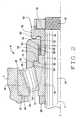
- the compensating bearing 8includes ( Figs. 1 and 2 ) a cup 48 that fits into the housing 2, a compensating assembly 50 that fits over the shaft 4, and tapered rollers 52 organized in a single row between the cup 48 and the compensating assembly 50.
- the cup 48may be conventional. As such, it has a tapered raceway 54 that is presented inwardly toward the axis X and a back face 56 that is perpendicular to the axis X.
- the cup 48fits into the internal seat 20 of the housing 2 with an interference fit and with its back face 56 against the shoulder 22 at the end of the seat 20.
- the tapered rollers 52are also conventional, and they lie in a single row along the raceway 54 of the cup 48 where they are also supported by the compensating assembly 50. Indeed, the compensating assembly 50 controls the exact axial position of the rollers 52 along the cup raceway 54, and that in turn controls the setting for the bearing system A.
- the compensating assembly 50fits over the bearing seat 24 on the shaft 4 between the cone spacer 28 and a nut 58 that is threaded over the external thread 26 at the end of the bearing seat 24. It includes ( Fig. 2 ) a ribless cone 60 and a biasing spacer 62 that fit over the bearing seat 24 where they are clamped tightly together between the cone spacer 28 and the nut 58.
- the compensating assembly 50has a shiftable rib ring 64 that is located generally around the cone 60 and biasing spacer 62, a biasing spring 66 that urges the rib ring 64 against the cone 60, and a thermal compensating ring 68 that exerts a force against the rib ring 64 in opposition to the force exerted by the spring 66, but only after the temperature of the compensating assembly 50 exceeds its normal operating temperature by a prescribed amount.
- the ribless cone 60fits over the bearing seat 24 of the shaft 4 with a prescribed fit. It has a tapered raceway 70 that is presented outwardly away from the axis X and toward raceway 54 of the cup 48 and is inclined in the same direction as the cup raceway 54.
- the tapered rollers 52are on apex, meaning that the conical envelopes in which their side faces lie as well as the conical envelopes in which the raceways 54 and 70 lie have their apices at a common point along the axis X.
- the raceway 70 of the cone 60leads up to a crowned land 72 which in turn leads out to a stop surface 74 that is perpendicular to the axis X.
- the cone 60also has an axial extension 76 that projects beyond the stop surface 74.
- the biasing spacer 62likewise fits over the bearing seat 24 of the shaft 4 with a prescribed fit, it being clamped tightly against the cone 60 by the lock nut 58. At one end it bears against the axial extension 76 of the cone 60. At its opposite end it has a flange 78 that projects radially outwardly behind the rib ring 64. Between the axial extension 76 of the cone 60 and the flange 78, the biasing spacer 62 has a cylindrical supporting surface 80 over which the compensating ring 68 fits.
- the shiftable rib ring 64fits loosely around the ribless cone 60 and the biasing spacer 62 where it has the capacity to shift axially a short distance. It has an axial rib 82 that provides a pilot bore 84 in which the crowned land 72 of the cone 60 is received. At the end of the bore 84 it has a rib face 86 against which the large end faces of the tapered rollers 52 bear.
- the pilot bore 84leads into an end surface 88 that normally abuts the stop surface 74 on the cone 60.
- the rib ring 64has an inwardly directed radial rib 90 that surrounds cylindrical supporting surface 80 of the biasing spacer 62.
- cylindrical confining surface 92that surrounds the axial extension 76 on the cone 60 and the cylindrical surface 80 of the biasing spacer 62, it being spaced outwardly from the latter to provide an annular cavity 94.
- a small clearanceexists between the confining surface 92 and the axial extension 76 and likewise between the radial rib 90 and the cylindrical supporting surface 80, so that the rib ring 64 can move easily over the cone 60 and biasing spacer 62.
- the thermal compensating ring 68occupies much of the annular cavity 94, it being supported around the cylindrical supporting surface 80 on the biasing spacer 62 and confined radially by the cylindrical confining surface 92 in the rib ring 64. Yet it is slightly shorter than the cavity 94 is long. In this regard, the end of the axial extension 76 on the cone 60 forms an abutment at one end of the cavity 94, whereas the radial rib 90 on the rib ring 64 forms an abutment at the opposite end of the cavity 94. Normally, when the compensating ring 68 at one of its ends is against one of the abutments a gap g exists between the other end of the ring 68 and the other abutment.
- the compensating ring 68is formed from a material having a high coefficient ( ⁇ ) of thermal expansion, considerably higher than the steel from which the cone 60, biasing spacer 62 and rib ring 64 are formed. Suitable materials include flurosilicon rubber, buna-N rubber, epichlorohydrin rubber, hypalon rubber and others.
- the compensating ring 68fits snugly between the cylindrical surfaces 80 and 92 of the biasing spacer 62 and the rib ring 64, respectively, and as a consequence is constrained radially. When its temperature rises, it can expand only axially. The confinement has the effect of increasing the linear coefficient of thermal expansion by a factor of 3.
- the biasing spring 66is compressed between the flange 78 of the biasing spacer 62 and the end of the rib ring 64. It urges the rib ring 64 against the cone 60, normally holding the two firmly together at the stop surface 74 on the cone 60 and the end surface 88 on the rib ring 64.
- the forceis 8 to 10 times the force normally exerted by the rollers 52 on the rib face 86 of the rib ring 64.
- the rib ring 64is normally seated into a positive stop against the cone 60, with the stop being provided by the stop surface 74 on the cone 60.
- biasing spring 66 depictedis a wave spring having circumferential undulations, it may take other forms such as a plurality of compression springs spaced at circumferential intervals along the flange 78 or a single compression spring around the biasing spacer 62..
- the compensating bearing 8prevents excessive preload in the bearing system A and this extends the life of the bearing ( Fig. 3 ). It requires consideration of several temperatures.
- Firstis the ambient temperature of the system A. This represents the temperature at which the system A, including its compensating bearing 8, is assembled. At that temperature the system A may exist in a state of end play or slight preload, but all components are essentially at the same temperature.
- Nextis the steady state operating temperature. This is the temperature to which the compensating assembly 50 rises and remains during normal operation of the system A. Typically, it corresponds to the temperature of the shaft 4 at the compensating assembly 50, but is less than the temperature of the cup 48 and the region of the housing 2 in which the cup 48 fits.
- a temperature differentialexists in the compensating bearing 8 when the compensating assembly 50 operates at its steady state operating temperature.
- the system Abecomes tighter, typically assuming a slight preload.
- the compensating ring 68remains inactive at the steady state operating temperature in the sense that it does not affect the position of the rib ring 64, because the gap g exists in the cavity 94 between the biasing spacer 62 and rib ring 64.
- the thermal set point temperaturefor the compensating assembly 50.
- the compensating assembly 50remains above the temperature of the cup 48 and housing 2, even more so.
- the thermal compensating ring 68has expanded enough to completely fill the cavity 94 and is on the verge of backing the rib ring 64 away from the cone 60.
- the compensating ring 68by reason of further expansion, holds the rib ring 64 away from the cone 60, and this serves to displace the rib face 86 farther up the tapered raceway 70 on the cone 60 and reduce the preload in the bearings 6 and 8.
- the choice of the activating temperature of the thermal rib set point, as well as the degree of thermal compensation after the set point has been reached,is based on the specific conditions of an application. Also, for the normal operation of the system A, the thermal set point may be offset any desired temperature differential above the steady state operating temperature to insure that the normal operation of the bearing system A is completely unaffected by the compensating assembly 50.
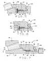
- a modified compensating assembly 100( Fig. 5 ) the ribless cone 60 and the biasing spacer 62 are coupled.
- the axial extension 76 on the cone 60overlies the end of the cylindrical supporting surface 80 on the biasing spacer 62.
- a dowel 102Extended through the overlying extension 76 and into the underlying biasing spacer 62 is a dowel 102, it having been inserted through an aligned clearance hole 104 in the rib ring 64.
- the dowel 102which is a coupling element, projects into the hole 104 to prevent the rib ring 64 from rotating against the cone 60, yet the clearance hole 104 is large enough to enable the rib ring 64 to displace axially after the thermal set point temperature is attained.
- the coupling of the cone 60 and biasing spacer 62eliminates the need for the cone spacer 28.
- a further variation in the form of another modified compensating assembly 110is easily disassembled.
- the flange 78is replaced by a back-up washer 112 and a retaining ring 114.
- the washer 112fits around the cylindrical supporting surface 80 of the biasing spacer 62, whereas the retaining ring 114 fits into a grove in the biasing spacer 62 and backs the back-up washer 112.
- a slot 116opens from the hole 104 through the end surface 88 of the rib ring 64 so that the dowel 102 does not interfere with withdrawal of the rib ring 64 over the biasing spacer 62.
- the cone 60 and biasing spacer 62are formed integral, providing an integrated ribless cone 122. Its cylindrical supporting surface 80 leads up to a shoulder 124 against which one end of the thermal compensating ring 68 bears.
- the assembly 120relies on a back-up washer 112 and retaining ring 114 to back the biasing spring 66. Like the compensating assemblies 100 and 110, the compensating assembly 120 requires no cone spacer 28 to hold it together.
- the normally abutting surface 74 and 88 on the ribless cone 60 and rib ring 64, respectively,are inclined at an oblique angle with respect to the axis X, in effect taking on frustoconical configurations centered on the axis X.
- the inclination of the surfaces 74 and 88centers the rib ring 64 around the cone 60 when the surfaces 74 and 88 abut, which is during the normal operation on the bearing 8 at the steady state operating temperature.
- a greater clearancemay exist between the crowned land 72 on the ribless cone 60 and the surface of the piloting bore 84 in the axial rib 82 of the rib ring 64.
- the compensating assembly 130utilizes a separate back-up plate 132 that is held against the end of the biasing spacer 62 with bolts 134 arranged in a bolt circle.
- the inclined abutting surfaces 74 and 88 on the cone 60 and rib ring 64 of the compensating assembly 130may be used with any of the compensating assemblies 50, 100, 110 and 120, and this holds true for the separate backing plate 132 as well.
- the thermal compensating ring 68may have end caps 140 ( Fig. 9 ) bonded to its ends to prevent the somewhat resilient and flexible material of the ring 68 from extruding into the clearances between the axial extension 76 on the cone 60 and the cylindrical confining surface 92 on the rib ring 64 and from extruding into the clearance between the cylindrical supporting surface 80 on the biasing spacer 62 and the radial rib 90 on the rib ring 64.
- Most materials from which the thermal compensating ring 68 may be formedhave a high coefficient of static friction.
- the compensating ring 68 on its surfaces that contact the cylindrical surfaces 80 and 92 on the biasing spacer 62 and rib ring 64, respectively,may be provided with a thin friction-reducing coating or treatment.
- the compensating ring 68may be fitted with thermal conductivity pins 144 ( Fig. 10 ) and 146 that telescope within the compensating ring 68 and have heads 148 that bear against the cone 60 and against the radial rib 90 of the rib ring 64 to transfer heat into or out of the thermal compensating ring 68.
- the pins 144 and 146are formed from a material of relatively high thermal conductivity, such as stainless steel.
- the compensating ring 68may completely fill the cavity 94 between the supporting surface in the biasing spacer 62 and the confining surface in the rib ring 64. With the compensating assembly so configured, it responds more rapidly to temperature excursions above the steady state operating temperature. This corresponds to a gap equal to zero and a set point temperature equal essentially to the steady state operating temperature.
- the cup 48may be formed integral with the housing 2, in which event its raceway 54 forms a surface of the housing 2.
Landscapes
- Engineering & Computer Science (AREA)
- General Engineering & Computer Science (AREA)
- Mechanical Engineering (AREA)
- Support Of The Bearing (AREA)
- Rolling Contact Bearings (AREA)
- Spinning Or Twisting Of Yarns (AREA)
- Rolls And Other Rotary Bodies (AREA)
- Soil Working Implements (AREA)
Abstract
Description
- This invention relates in general to tapered roller bearings and more particularly to tapered roller bearings having displaceable ribs that compensate for thermal differentials and to a method of controlling the setting in bearings.
- A tapered roller bearing in its simplest form has a cup (outer race) that is typically fitted to a housing, a cone (inner race) that is typically fitted over a shaft, and tapered rollers (rolling elements) organized in a single row between the cup and cone. The cup and cone have tapered raceways that the rollers along their tapered side faces contact. In addition, the cone at the large end of its raceway has a thrust rib against which the large end faces of the rollers bear, and it prevents the rollers from being expelled from the annular space between the raceways. The thrust rib forms an integral part of the cone and cannot be displaced with respect to the cone.
- A single row tapered roller bearing has the capacity to support or transfer radial loads and also axial loads in one axial direction. A bearing system composed of two single row tapered roller bearings mounted in opposition will transfer not only radial loads, but also axial loads in both axial directions, and will thus confine that which rotates both radially and axially. When mounted in opposition, the bearings may assume either the indirect configuration or the direct configuration. In the indirect configuration the small ends of the rollers of the one bearing are presented toward the small ends of the rollers for the other bearing. In the direct configuration the two bearings have the opposite orientation. Irrespective of the mounting configuration, the bearings may be adjusted to a desired setting by shifting only one of the races of either bearing axially. The setting may be various degrees of end play, in which clearances exist within the bearings, or various degrees of preload, which are characterized by the absence of clearances and increased dynamic stiffness for the axis of rotation. Another condition of line-to-line contact, often referred to as zero end play, is difficult to maintain. A light preload is preferred, but too much preload can damage the bearings.
- Assuming that the two bearings are mounted in the indirect configuration and that the shaft and cones rise in temperature above the temperature of the housing and the cups, the differential thermal expansion between the shaft and cones, on one hand, and the cup and housing, on the other, produces two counteracting disruptions to the setting for the bearings. First, the axial expansion of the shaft tends to reduce or eliminate the slight preload. On the other hand, the radial expansion of the cones tends to increase the preload. The amount that one prevails over the other depends on the axial spread between the bearings, the diameter of the cones, and the angles of the raceways. Generally speaking, the radial expansion more than offsets the axial expansion, and when it does the bearings acquire a greater preload.
- With directly mounted bearings, both the axial expansion and the radial expansion contribute to an increase in preload.
- Stated somewhat differently, tapered roller bearings generate internal axial reaction forces due to the raceway angles. This typically means that a pair of single row tapered roller bearings are used in opposition so that the axial forces may be cancelled out against each other. Also, this allows the pair of bearings to carry external loads in any direction of application. At setup, a careful and precise axial location adjustment of the opposed races relative to each other is required. This process is called bearing setting and produces either endplay, line-to-line contact, or preload.
- While a slight preload is desirable for a pair of single row tapered roller bearings mounted on opposition, too much preload is detrimental. Differential thermal expansion between the cones and cups and the shaft and housing to which they are respectively fitted can produce excessive preload. That preload may:
- reduce bearing life
- increase bearing noise and vibration
- increase bearing generated heat
- increase bearing torque
- increase damage to bearing lubricant
- increase roller contact stress
- increase cage damage
- Heretofore, efforts have been made to compensate for differential thermal expansion in bearing systems having opposed single row bearings. One involves installing a compensating ring having a high coefficient of thermal expansion behind one of the four races of the system. The thermal expansion of the compensating ring generally offsets the differential thermal expansion otherwise experienced by the bearing system, so that the system remains within acceptable tolerances. See
U.S. Patent 5,028,152 . Another effort involves controlling the position of the thrust rib in one of the bearings with pressurized hydraulic fluid. SeeU.S. Patent 3,716,280 . - The invention resides in a compensating bearing having tapered rollers organized in a row between tapered raceways, with the axial position of the rollers and the setting for the system, of which the bearing is a part, being controlled by a rib ring that is displaced from a normal operating position by a compensating ring having a high coefficient of thermal expansion, so as to control the setting of the bearing. The invention also resides in a method of controlling a bearing setting with the displaceable rib ring and compensating ring.
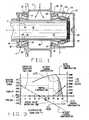
Figure 1 is a sectional view of a bearing system interposed between a shaft and a housing and provided with a compensating bearing constructed in accordance with and embodying the present invention;Figure 2 is an enlarged half-sectional view of the compensating bearing;Figure 3 is a graph depicting the life of the bearing system and operating condition for the bearing system as a function or temperature differential in the bearing system;Fig. 4 shows graphs depicting operating conditions of the compensating ring and bearing system during temperature rise and cool down;Figs. 5-8 are a fragmentary sectional views of modified compensating assemblies for the compensating bearing of the bearing system.Fig. 9 is fragmentary sectional view of a compensating assembly containing a compensating ring having end caps; andFig. 10 is a fragmentary sectional view of a compensating assembly containing compensating rings having conductivity pins for enhancing transfer of heat into or out of the compensating ring.- Referring now to the drawings, a bearing system A (
Fig. 1 ) exists between ahousing 2 and a shaft 4 to enable one to rotate relative to the other about an axis X. For example, thehousing 2 may remain fixed and the shaft 4 may rotate in it. On the other hand, the shaft 4 may take the form of a fixed spindle about which thehousing 2 rotates, in which event thehousing 2 may be a hub. The bearing system A includes two antifriction bearings-namely a single row tapered roller bearing 6 of conventional design and another single row tapered roller bearing 8 configured to compensate for differential thermal expansion betweenhousing 2 and shaft 4 as well as between components of thebearings bearings housing 2 and shaft 4 and axial (thrust) loads in both axial directions as well. The system A as illustrated has thebearings bearing 6 could take the form of some other antifriction bearing, such as an angular contact ball bearing designed to transfer both radial and axial loads, or it could even be another compensating bearing as is thebearing 8. - At the
conventional bearing 6, thehousing 2 has aninternal bearing seat 12 and a shoulder 14 at the end of theseat 12. The shaft 4 has anexternal bearing seat 16 that leads to anothershoulder 18. At the compensatingbearing 8, thehousing 2 has anotherinternal seat 20 andshoulder 22. Here the shaft 4 has anotherexternal seat 24 that leads out to anexternal thread 26. Separating the twobearings cone spacer 28. - Being a single row tapered roller bearing of conventional design, the
bearing 6 has acup 32 provided with a taperedraceway 34, a cone 36 provided with a tapered raceway 38 that leads up to athrust rib 40 that is an integral part of the cone 36, and taperedrollers 42 that are located between thecup 32 and cone 36 where they roll along theraceways 34 and 38 with their large end faces against thethrust rib 40. Indeed, thethrust rib 40 prevents therollers 42 from working up theraceways 34 and 38 and being expelled from the annular space between them. Thecup 32 fits into theinternal seat 12 of thehousing 2 and against the shoulder 14 which serves to fix its axial position. The cone 36 fits over theexternal seat 16 on the shaft 4 and with its large end against theshoulder 18, which fixes its axial position. Thecone spacer 28 bears against the small end of the cone 36. - The compensating
bearing 8 includes (Figs. 1 and2 ) acup 48 that fits into thehousing 2, a compensatingassembly 50 that fits over the shaft 4, and taperedrollers 52 organized in a single row between thecup 48 and the compensatingassembly 50. Thecup 48 may be conventional. As such, it has a taperedraceway 54 that is presented inwardly toward the axis X and aback face 56 that is perpendicular to the axis X. Thecup 48 fits into theinternal seat 20 of thehousing 2 with an interference fit and with itsback face 56 against theshoulder 22 at the end of theseat 20. The taperedrollers 52 are also conventional, and they lie in a single row along theraceway 54 of thecup 48 where they are also supported by the compensatingassembly 50. Indeed, the compensatingassembly 50 controls the exact axial position of therollers 52 along thecup raceway 54, and that in turn controls the setting for the bearing system A. - The compensating
assembly 50 fits over the bearingseat 24 on the shaft 4 between thecone spacer 28 and anut 58 that is threaded over theexternal thread 26 at the end of the bearingseat 24. It includes (Fig. 2 ) aribless cone 60 and a biasingspacer 62 that fit over the bearingseat 24 where they are clamped tightly together between thecone spacer 28 and thenut 58. In addition, the compensatingassembly 50 has ashiftable rib ring 64 that is located generally around thecone 60 and biasingspacer 62, a biasingspring 66 that urges therib ring 64 against thecone 60, and a thermal compensatingring 68 that exerts a force against therib ring 64 in opposition to the force exerted by thespring 66, but only after the temperature of the compensatingassembly 50 exceeds its normal operating temperature by a prescribed amount.. - The
ribless cone 60 fits over the bearingseat 24 of the shaft 4 with a prescribed fit. It has a taperedraceway 70 that is presented outwardly away from the axis X and towardraceway 54 of thecup 48 and is inclined in the same direction as thecup raceway 54. The taperedrollers 52 are on apex, meaning that the conical envelopes in which their side faces lie as well as the conical envelopes in which theraceways raceway 70 of thecone 60 leads up to a crownedland 72 which in turn leads out to astop surface 74 that is perpendicular to the axis X. Thecone 60 also has anaxial extension 76 that projects beyond thestop surface 74. - The biasing
spacer 62 likewise fits over the bearingseat 24 of the shaft 4 with a prescribed fit, it being clamped tightly against thecone 60 by thelock nut 58. At one end it bears against theaxial extension 76 of thecone 60. At its opposite end it has aflange 78 that projects radially outwardly behind therib ring 64. Between theaxial extension 76 of thecone 60 and theflange 78, the biasingspacer 62 has a cylindrical supportingsurface 80 over which the compensatingring 68 fits. - The
shiftable rib ring 64 fits loosely around theribless cone 60 and the biasingspacer 62 where it has the capacity to shift axially a short distance. It has anaxial rib 82 that provides a pilot bore 84 in which the crownedland 72 of thecone 60 is received. At the end of thebore 84 it has arib face 86 against which the large end faces of the taperedrollers 52 bear. Thus, therib 82 not only prevents therollers 52 from being expelled from the annular space between theraceways rollers 52 along theraceways end surface 88 that normally abuts thestop surface 74 on thecone 60. At its opposite end therib ring 64 has an inwardly directedradial rib 90 that surrounds cylindrical supportingsurface 80 of the biasingspacer 62. Between theflange 90 and theend surface 88 is cylindrical confiningsurface 92 that surrounds theaxial extension 76 on thecone 60 and thecylindrical surface 80 of the biasingspacer 62, it being spaced outwardly from the latter to provide anannular cavity 94. A small clearance exists between the confiningsurface 92 and theaxial extension 76 and likewise between theradial rib 90 and the cylindrical supportingsurface 80, so that therib ring 64 can move easily over thecone 60 and biasingspacer 62. - The thermal compensating
ring 68 occupies much of theannular cavity 94, it being supported around thecylindrical supporting surface 80 on the biasingspacer 62 and confined radially by thecylindrical confining surface 92 in therib ring 64. Yet it is slightly shorter than thecavity 94 is long. In this regard, the end of theaxial extension 76 on thecone 60 forms an abutment at one end of thecavity 94, whereas theradial rib 90 on therib ring 64 forms an abutment at the opposite end of thecavity 94. Normally, when the compensatingring 68 at one of its ends is against one of the abutments a gap g exists between the other end of thering 68 and the other abutment. The compensatingring 68 is formed from a material having a high coefficient (∝) of thermal expansion, considerably higher than the steel from which thecone 60, biasingspacer 62 andrib ring 64 are formed. Suitable materials include flurosilicon rubber, buna-N rubber, epichlorohydrin rubber, hypalon rubber and others. The compensatingring 68 fits snugly between thecylindrical surfaces spacer 62 and therib ring 64, respectively, and as a consequence is constrained radially. When its temperature rises, it can expand only axially. The confinement has the effect of increasing the linear coefficient of thermal expansion by a factor of 3. - The biasing
spring 66 is compressed between theflange 78 of the biasingspacer 62 and the end of therib ring 64. It urges therib ring 64 against thecone 60, normally holding the two firmly together at thestop surface 74 on thecone 60 and theend surface 88 on therib ring 64. Typically, the force is 8 to 10 times the force normally exerted by therollers 52 on therib face 86 of therib ring 64. Thus, therib ring 64 is normally seated into a positive stop against thecone 60, with the stop being provided by thestop surface 74 on thecone 60. While the biasingspring 66 depicted is a wave spring having circumferential undulations, it may take other forms such as a plurality of compression springs spaced at circumferential intervals along theflange 78 or a single compression spring around the biasingspacer 62.. - In the operation of the bearing system A, radial loads transfer between the
housing 2 and shaft 4 at the twobearings conventional bearing 6 and axial loads on the other direction transfer through the compensatingbearing 8. At theconventional bearing 6 both the radial and axial loads transfer through therollers 42 at theraceways 34 and 38 on thecup 32 and cone 36, respectively. At theconventional bearing 6 theshoulders 14 and 16 against which thecup 32 and cone 36 respectively bear take the axial loads transferred through thatbearing 6. At the compensatingbearing 8 the radial loads and axial loads transfer through the taperedrollers 52 at theraceways cup 48 andcone 60, respectively. Theshoulder 22 at the end of the bearingseat 20 in thehousing 2 takes the axial loads applied to thecup 48. Thenut 58 that engages thethreads 26 on the shaft 4 and bears against the biasingspacer 62 takes the axial loads applied to thecone 60. Also, thenut 58, reacting against thethreads 26, creates a condition of axial compression in the biasingspacer 52, theribless cone 60, thecone spacer 28, the conventional cone 36 andshaft shoulder 18. - The compensating
bearing 8 prevents excessive preload in the bearing system A and this extends the life of the bearing (Fig. 3 ). It requires consideration of several temperatures. First is the ambient temperature of the system A. This represents the temperature at which the system A, including its compensatingbearing 8, is assembled. At that temperature the system A may exist in a state of end play or slight preload, but all components are essentially at the same temperature. Next is the steady state operating temperature. This is the temperature to which the compensatingassembly 50 rises and remains during normal operation of the system A. Typically, it corresponds to the temperature of the shaft 4 at the compensatingassembly 50, but is less than the temperature of thecup 48 and the region of thehousing 2 in which thecup 48 fits. Thus, a temperature differential exists in the compensatingbearing 8 when the compensatingassembly 50 operates at its steady state operating temperature. The system A becomes tighter, typically assuming a slight preload. The compensatingring 68 remains inactive at the steady state operating temperature in the sense that it does not affect the position of therib ring 64, because the gap g exists in thecavity 94 between the biasingspacer 62 andrib ring 64. Then there is the thermal set point temperature for the compensatingassembly 50. At this temperature the compensatingassembly 50 remains above the temperature of thecup 48 andhousing 2, even more so. Moreover, at the thermal set point temperature the thermal compensatingring 68 has expanded enough to completely fill thecavity 94 and is on the verge of backing therib ring 64 away from thecone 60. Beyond the thermal set point temperature, the compensatingring 68, by reason of further expansion, holds therib ring 64 away from thecone 60, and this serves to displace therib face 86 farther up the taperedraceway 70 on thecone 60 and reduce the preload in thebearings - 1. The normal operation of the bearing system A causes a temperature rise in the compensating
assembly 50, including the compensatingring 68 of the compensatingbearing 8, above temperature of thecup 48 for that bearing due to normal expected loads, speeds and torques until the desired and expected steady state operating temperature has been reached. This assumes that the bearing system A has either never yet exceeded the thermal rib set point, or that sufficient time has elapsed to zero out any thermal lag induced expansion. - 2. The length of the thermal compensating
ring 68 is such as to leave a small gap g, so that the effect of the thermal compensation is zero below the thermal set point temperature. - 3. The biasing
spring 66 is selected to produce typically 8 to 10 times the maximum normal contact force between therollers 52 andaxial rib 82 of therib ring 64, so that therib ring 64 is always positively seated against thestop surface 74 of thecone 60. This guarantees that the operation of the bearing system A at the desired normal steady state operating temperature is no different than for a traditional tapered roller bearing system. - 1. During operation larger than expected shaft speeds or application loads may produce added frictional heat from the contact between the
rib face 86 of therib ring 64 and the large end faces of therollers 52. Also, the shaft 4 may conduct additional heat from gear tooth contact or other external heat generation sources. This can cause theribless cone 60,rollers 42,movable rib ring 64, shaft 4, thermal compensatingring 68, and the biasing spacer 62 - in short, the compensating assembly 50-to experience a further temperature increase. The thermal conductivity of the thermal compensatingring 68 is much lower than for the materials, normally steel, of themovable rib ring 64,rollers 52,cone 60, shaft 4, and the biasingring 62. Consequently, a short time of thermal lag develops during which a slight increase in preload may occur due to the ∝ thermal linear coefficient of expansion for those materials. - 2. The thermal compensating
ring 68 reaches its new temperature. Its ∝ coefficient of thermal linear expansion is considerably larger than that of the other materials, and thering 68 expands dramatically. - 3. Because the material of the thermal compensating
ring 68 is constrained from radial expansion, the volumetric expansion that occurs is transformed almost entirely into axial expansion and is proportional to 3 times the linear expansion, or 3 ∝. - 4. No thermal compensation effect occurs, however, until the material rises to a temperature that allows the compensating
ring 68 to expand completely through the gap g distance. That temperature is the thermal set point temperature. This causes the thermal effect to be disabled below the thermal set point temperature, giving it an on-off effect as well as a proportional temperature characteristic. The passive design acts in a way that is somewhat more directed, almost as if it was an active control. The net effect is of a preload limiter or bearing overload prevention device. - 5. Once the gap g distance has been overcome, the volumetric expansion of the constrained thermal compensating
ring 68 begins to exert axial force and continues to build up sufficient force to unseat themovable rib ring 64 from thepositive stop surface 74 on thecone 60 as thering 68 overcomes the biasing force of thespring 66. Themoveable rib ring 64 and itsaxial rib 82 retract, thus compensating for the thermal expansion effects in the materials of thebearing 8 and shaft 4. (Fig. 3 ). However, the size of the gap g and the length of the thermal compensatingring 68 determine the temperature value for the thermal rib set point as well as the shape (slope) of the compensation effect.- a. Or, Slope (inch/degree F) = 3 x ∝ x L where ∝ is the linear coefficient of thermal expansion for the material of the compensating
ring 68; - b. L is the length of the thermal compensating
ring 68 at the reference temperature of the mountedcup 48 andhousing 2, and ∝ units are (inch/inch degree F); - c. And, gap g (inch) = 3 x ∝ x L ((thermal set point temperature - steady state operating temperature));
- d. The thermal set point temperature and steady state operating temperature represent states in which differences in temperature between the temperature of the
cup 48 andhousing 2 and the temperature at the compensatingassembly 50 and shaft 4. The gap equation above uses the temperature difference between these two states which are themselves differential values; and - e. The compensating
assembly 50 does not physically use differential temperatures to activate itself. The thermal compensatingring 68 simply responds to the heat flux input it either receives or loses from or to its surroundings. It will not know if that heat is due to elevated differential temperatures of thecone 60 and shaft 4 relative to thecup 48 andhousing 2 or vice versa. Proper response of the compensatingassembly 50 assumes that the application is understood well enough to determine which components of the system A will experience a temperature increase, so that the desired preload control may be obtained.
- a. Or, Slope (inch/degree F) = 3 x ∝ x L where ∝ is the linear coefficient of thermal expansion for the material of the compensating
- Therefore the choice of the activating temperature of the thermal rib set point, as well as the degree of thermal compensation after the set point has been reached, is based on the specific conditions of an application. Also, for the normal operation of the system A, the thermal set point may be offset any desired temperature differential above the steady state operating temperature to insure that the normal operation of the bearing system A is completely unaffected by the compensating
assembly 50. - 1. Once conditions no longer exist in the bearing system A that created the excess heat, the thermal compensating
ring 68 begins to cool and reduce the thermal compensating effect which is no longer required or desirable. The compensatingassembly 50 prevents bearing heat from increasing preload and becoming more severe (Fig. 3 ), but it does not remove the root cause for the heat production such as increase in speed or external load or external heat source. Because for most of the thermal compensating materials the thermal conductivity is much less than that of the outer materials in the compensating assembly 50 (typically steel), a condition of thermal lag or thermal hysteresis will occur. Assuming that the cool down process is slow enough, the cool down operating setting line will follow closely line M inFigure 4 , and the thermal lag effects on the bearing setting will be minimal. - 2. For situations which result in a fairly quick cool down of the bearing system A, the cool down of the thermal compensating
ring 68 will experience a greater thermal lag to the other materials (Fig. 4 ). This would cause the bearing system A to operate for a short time at a slightly looser setting than desired. The cool down operating setting line that will actually occur will be like line N ofFigure 4 . However, if the system operating point was a preload setting, the thermal lag is partly or almost completely offset by the original system preload. Thus, the preload may be temporarily reduced, but the system A may never enter the endplay condition at all. Should the system A enter endplay, it will be only until thermal equilibrium is reestablished, at which time the system will return to the operating condition preload once again. - Variations of the compensating
assembly 50 for the compensatingbearing 8 are possible. - In a modified compensating assembly 100 (
Fig. 5 ), theribless cone 60 and the biasingspacer 62 are coupled. To that end, theaxial extension 76 on thecone 60 overlies the end of the cylindrical supportingsurface 80 on the biasingspacer 62. Extended through theoverlying extension 76 and into theunderlying biasing spacer 62 is adowel 102, it having been inserted through an alignedclearance hole 104 in therib ring 64. Thedowel 102, which is a coupling element, projects into thehole 104 to prevent therib ring 64 from rotating against thecone 60, yet theclearance hole 104 is large enough to enable therib ring 64 to displace axially after the thermal set point temperature is attained. The coupling of thecone 60 and biasingspacer 62 eliminates the need for thecone spacer 28. - A further variation in the form of another modified compensating assembly 110 (
Fig. 6 ) is easily disassembled. To that end, theflange 78 is replaced by a back-upwasher 112 and a retainingring 114. Thewasher 112 fits around thecylindrical supporting surface 80 of the biasingspacer 62, whereas the retainingring 114 fits into a grove in the biasingspacer 62 and backs the back-upwasher 112. Moreover, where thedowel 102 projects into theclearance hole 104, aslot 116 opens from thehole 104 through theend surface 88 of therib ring 64 so that thedowel 102 does not interfere with withdrawal of therib ring 64 over the biasingspacer 62. - In still another compensating assembly 120 (
Fig. 7 ), thecone 60 and biasingspacer 62 are formed integral, providing anintegrated ribless cone 122. Its cylindrical supportingsurface 80 leads up to ashoulder 124 against which one end of the thermal compensatingring 68 bears. Theassembly 120 relies on a back-upwasher 112 and retainingring 114 to back the biasingspring 66. Like the compensatingassemblies assembly 120 requires nocone spacer 28 to hold it together. - In yet another modified compensating assembly 130 (
Fig. 8 ) the normally abuttingsurface ribless cone 60 andrib ring 64, respectively, are inclined at an oblique angle with respect to the axis X, in effect taking on frustoconical configurations centered on the axis X. The inclination of thesurfaces rib ring 64 around thecone 60 when thesurfaces bearing 8 at the steady state operating temperature. As a consequence, a greater clearance may exist between the crownedland 72 on theribless cone 60 and the surface of the pilotingbore 84 in theaxial rib 82 of therib ring 64. Only when the compensatingassembly 50 operates above the thermal set point temperature may therib ring 64 go slightly off center, but that is acceptable for the relatively short duration of thermal transients when the compensatingassembly 130 actively provides thermal compensation. In lieu of anintegral flange 78 for backing the biasingspring 66 or a separate back-upwasher 112, the compensatingassembly 130 utilizes a separate back-upplate 132 that is held against the end of the biasingspacer 62 withbolts 134 arranged in a bolt circle. - The inclined abutting
surfaces cone 60 andrib ring 64 of the compensatingassembly 130 may be used with any of the compensatingassemblies separate backing plate 132 as well. - The thermal compensating
ring 68 may have end caps 140 (Fig. 9 ) bonded to its ends to prevent the somewhat resilient and flexible material of thering 68 from extruding into the clearances between theaxial extension 76 on thecone 60 and the cylindrical confiningsurface 92 on therib ring 64 and from extruding into the clearance between the cylindrical supportingsurface 80 on the biasingspacer 62 and theradial rib 90 on therib ring 64. Most materials from which the thermal compensatingring 68 may be formed have a high coefficient of static friction. To aid in the capacity to transform volumetric expansion into linear expansion while reducing shearing stresses, the compensatingring 68 on its surfaces that contact thecylindrical surfaces spacer 62 andrib ring 64, respectively, may be provided with a thin friction-reducing coating or treatment. - Also, to enable the compensating
ring 68 to respond more quickly to changes in temperature, particularly to temperature rises above the thermal set point temperature, the compensatingring 68 may be fitted with thermal conductivity pins 144 (Fig. 10 ) and 146 that telescope within the compensatingring 68 and haveheads 148 that bear against thecone 60 and against theradial rib 90 of therib ring 64 to transfer heat into or out of the thermal compensatingring 68. Thepins - At the steady state operating temperature, the compensating
ring 68 may completely fill thecavity 94 between the supporting surface in the biasingspacer 62 and the confining surface in therib ring 64. With the compensating assembly so configured, it responds more rapidly to temperature excursions above the steady state operating temperature. This corresponds to a gap equal to zero and a set point temperature equal essentially to the steady state operating temperature. - The
cup 48 may be formed integral with thehousing 2, in which event itsraceway 54 forms a surface of thehousing 2.
Claims (14)
- A tapered roller bearing for use as one of two opposed bearings that may be adjusted against each other along an axis (x) to a desired setting, said bearing comprising:a cup (48) having a tapered raceway (54) presented inwardly toward the axis (x);a cone (60) having a tapered raceway (70) presented away from the axis and toward the raceway on the cup and having a stop surface (74) presented at an angle with respect to the axis;a rib ring (64) located opposite the stop surface of the cone having a rib face (88) located at the large end of the raceway on the cone;a spring (66) exerting a force that biases the rib ring toward and normally against the stop surface (74) on the cone;a thermal compensating ring (68) positioned to exert on the rib ring (64) a force that opposes the force exerted by the spring (66) so as to urge the rib ring (64) away from the stop surface (74) on the cone (60) when the temperature of the compensating ring (68) exceeds a thermal set point temperature; andtapered rollers (52) located between and contacting the raceways (54, 70) of the cup and cone and having their large end faces against the rib face on the rib ring.
- A tapered roller bearing according to claim 1 wherein the thermal compensating ring lies between an abutment on the rib ring and an abutment on the cone; and wherein below the thermal set point temperature a gap exists between at least one of the abutments and the compensating ring.
- A tapered roller bearing according to claim 1 wherein a supporting surface extends axially from the cone and the rib ring has a confining surface that surrounds the supporting surface; and
wherein the compensating ring is constrained radially by the supporting and confining surfaces. - A tapered roller bearing according to claim 3 wherein the supporting and confining surfaces are cylindrical and parallel to the axis.
- A tapered roller bearing according to claim 3 and further comprising a biasing spacer located in a fixed portion with respect to the cone and having a backing against which the spring bears; and
wherein the supporting surface is on the biasing spacer. - A tapered roller bearing according to claim 5 wherein the cone and the biasing spacer are coupled.
- A tapered roller bearing according to claim 6 wherein a coupling element extends through the cone and the biasing spacer to couple them.
- A tapered roller bearing according to claim 5 wherein the cone and the biasing spacer are integrally united into an integral cone.
- A tapered roller bearing according to claim 2 wherein the compensating ring is shorter than the distance between the abutments when the temperature of the compensating ring is below the prescribed value.
- A typical roller bearing according to claim 1 wherein the cone has a land at the large end of its raceway and the rib ring has a rib that surrounds the land and carries the rib face.
- A tapered roller bearing according to claim 1 wherein the stop surface is inclined at an oblique angle with respect to the axis, and the rib ring has end surface along which it abuts the stop surface, with the end surface being inclined at a similar oblique angle to the axis.
- A method of preventing excessive preload in a tapered roller bearing that facilitates rotation about an axis (x) and has a cup (48) and a cone (60) provided with tapered raceways (54, 70) and tapered rollers (52) arranged in a row between raceways, said method comprising:positioning a rib ring (64) at one end of the cone, with the rib ring being axially displaceable relative to the cone and having a rib face (88) at the large end of the cone raceway;urging the rib ring (64) toward a normal operating position; andwith a compensating ring (68) formed from a material having a coefficient of thermal expansion higher than the material from which the cone (60) and rib ring (64) are formed, urging the rib ring (64) away from the cone (60) when the temperature of the rib ring (64) rises so as to displace the rib face (88) farther up the raceway of the cone and reduce preload in the bearing.
- A method according to claim 12 wherein the compensating ring displaces the rib ring when the temperature of the compensating ring reaches a magnitude higher than the normal steady state operating temperature of the cone and the rib ring.
- A method according to claim 12 and further comprising constraining the compensating ring radially.
Applications Claiming Priority (2)
| Application Number | Priority Date | Filing Date | Title |
|---|---|---|---|
| US81770806P | 2006-06-30 | 2006-06-30 | |
| PCT/US2007/072323WO2008005788A2 (en) | 2006-06-30 | 2007-06-28 | Tapered roller bearing with displaceable rib |
Publications (2)
| Publication Number | Publication Date |
|---|---|
| EP2035722A2 EP2035722A2 (en) | 2009-03-18 |
| EP2035722B1true EP2035722B1 (en) | 2009-11-18 |
Family
ID=38719079
Family Applications (1)
| Application Number | Title | Priority Date | Filing Date |
|---|---|---|---|
| EP07812409ANot-in-forceEP2035722B1 (en) | 2006-06-30 | 2007-06-28 | Tapered roller bearing with displaceable rib |
Country Status (7)
| Country | Link |
|---|---|
| US (1) | US8356944B2 (en) |
| EP (1) | EP2035722B1 (en) |
| CN (1) | CN101484716B (en) |
| AT (1) | ATE449266T1 (en) |
| DE (1) | DE602007003359D1 (en) |
| ES (1) | ES2334173T3 (en) |
| WO (1) | WO2008005788A2 (en) |
Cited By (2)
| Publication number | Priority date | Publication date | Assignee | Title |
|---|---|---|---|---|
| DE102013215558A1 (en) | 2013-08-07 | 2015-02-12 | Aktiebolaget Skf | Device for compensating a temperature-induced radial change in bias in a rolling bearing assembly |
| US11365763B2 (en) | 2018-12-06 | 2022-06-21 | Danfoss Power Solutions Inc. | Cover plate and seal carrier that eliminates bearing endplay |
Families Citing this family (20)
| Publication number | Priority date | Publication date | Assignee | Title |
|---|---|---|---|---|
| DE102010035062A1 (en)* | 2010-08-21 | 2012-02-23 | Schaeffler Technologies Gmbh & Co. Kg | Tapered roller bearing with cage |
| WO2012097962A2 (en)* | 2011-01-17 | 2012-07-26 | Fm Energie Gmbh & Co.Kg | Anti-friction bearing which can be prestressed hydraulically |
| JP5417481B2 (en)* | 2012-04-20 | 2014-02-12 | ナブテスコ株式会社 | Gear transmission |
| US9115756B2 (en)* | 2013-02-27 | 2015-08-25 | Dresser-Rand Company | Replaceable axial journal for auxiliary bearings |
| US20160053812A1 (en)* | 2013-03-28 | 2016-02-25 | Aktiebolaget Skf | Bearing assembly and method for assembling and mounting said bearing assembly with a component supporting said bearing assembly |
| DE102014214999B4 (en)* | 2014-07-30 | 2021-06-24 | Aktiebolaget Skf | Bearing arrangement with preload |
| DE102014225029B4 (en)* | 2014-12-05 | 2025-06-05 | Aktiebolaget Skf | Temperature compensation ring, bearing ring and bearing arrangement |
| DE102015212311A1 (en)* | 2015-07-01 | 2017-01-05 | Aktiebolaget Skf | bearing arrangement |
| KR102641707B1 (en)* | 2015-08-04 | 2024-02-29 | 섀플러 테크놀로지스 아게 운트 코. 카게 | Manufacturing method and device for each contact roller bearing |
| DE102015220962B4 (en)* | 2015-10-27 | 2022-06-30 | Aktiebolaget Skf | Bearing arrangement with preload |
| JP2017096347A (en)* | 2015-11-19 | 2017-06-01 | アイシン・エーアイ株式会社 | transmission |
| DE102016209997A1 (en) | 2016-06-07 | 2017-12-07 | Audi Ag | Gear arrangement for a motor vehicle |
| JP6394670B2 (en) | 2016-10-06 | 2018-09-26 | トヨタ自動車株式会社 | Power transmission device for vehicle |
| US10087986B2 (en)* | 2016-10-18 | 2018-10-02 | Aktiebolaget Skf | Temperature compensation ring as well as bearing ring with the temperature compensation ring |
| DE102017130482A1 (en)* | 2017-02-24 | 2018-08-30 | Schaeffler Technologies AG & Co. KG | Hybrid module and powertrain for a motor vehicle and method of assembling a powertrain |
| WO2019156720A1 (en)* | 2018-02-07 | 2019-08-15 | The Timken Company | Roller seating device for tapered roller bearings |
| WO2020090520A1 (en)* | 2018-10-31 | 2020-05-07 | Ntn株式会社 | Bearing device |
| GB2589706B (en)* | 2019-09-23 | 2023-08-23 | Skf Ab | High-speed bearing with grooved and cylindrical races |
| CN111765237B (en)* | 2020-09-03 | 2020-12-22 | 盛瑞传动股份有限公司 | Output shaft support device for transmission |
| CN114759717A (en)* | 2022-03-31 | 2022-07-15 | 浙江吉利控股集团有限公司 | Clearance thermal compensation structure and rotating device |
Family Cites Families (8)
| Publication number | Priority date | Publication date | Assignee | Title |
|---|---|---|---|---|
| US2195795A (en)* | 1938-07-05 | 1940-04-02 | Timken Roller Bearing Co | Roller bearing |
| US2836473A (en)* | 1957-07-26 | 1958-05-27 | Clarence W Tydeman | Mounting for preloading tapered roller bearings |
| BE787637A (en)* | 1971-12-20 | 1973-02-19 | Timken Co | BEARING STRUCTURE |
| DE3239305A1 (en) | 1982-10-23 | 1984-04-26 | Zahnradfabrik Friedrichshafen Ag, 7990 Friedrichshafen | Axial bearing support |
| US5028152A (en)* | 1990-03-21 | 1991-07-02 | The Timken Company | Machine with thermally compensated bearings |
| US6135641A (en)* | 1997-10-30 | 2000-10-24 | Honeywell International Inc. | Hybrid duplex bearing assembly having thermal compensation |
| US20060018582A1 (en) | 2004-07-26 | 2006-01-26 | Mircea Gradu | Bearing having thermal compensating capability |
| JP2008507678A (en)* | 2004-07-26 | 2008-03-13 | ザ ティムケン カンパニー | Bearing with thermal compensation capability |
- 2007
- 2007-06-28USUS12/306,302patent/US8356944B2/ennot_activeExpired - Fee Related
- 2007-06-28EPEP07812409Apatent/EP2035722B1/ennot_activeNot-in-force
- 2007-06-28ATAT07812409Tpatent/ATE449266T1/ennot_activeIP Right Cessation
- 2007-06-28WOPCT/US2007/072323patent/WO2008005788A2/enactiveApplication Filing
- 2007-06-28CNCN2007800247835Apatent/CN101484716B/ennot_activeExpired - Fee Related
- 2007-06-28DEDE602007003359Tpatent/DE602007003359D1/enactiveActive
- 2007-06-28ESES07812409Tpatent/ES2334173T3/enactiveActive
Cited By (3)
| Publication number | Priority date | Publication date | Assignee | Title |
|---|---|---|---|---|
| DE102013215558A1 (en) | 2013-08-07 | 2015-02-12 | Aktiebolaget Skf | Device for compensating a temperature-induced radial change in bias in a rolling bearing assembly |
| DE102013215558B4 (en) | 2013-08-07 | 2020-08-06 | Aktiebolaget Skf | Device for compensating a temperature-related radial preload change in a rolling bearing arrangement |
| US11365763B2 (en) | 2018-12-06 | 2022-06-21 | Danfoss Power Solutions Inc. | Cover plate and seal carrier that eliminates bearing endplay |
Also Published As
| Publication number | Publication date |
|---|---|
| EP2035722A2 (en) | 2009-03-18 |
| WO2008005788A2 (en) | 2008-01-10 |
| ES2334173T3 (en) | 2010-03-05 |
| CN101484716B (en) | 2011-02-09 |
| CN101484716A (en) | 2009-07-15 |
| WO2008005788A3 (en) | 2008-02-21 |
| US8356944B2 (en) | 2013-01-22 |
| US20090202188A1 (en) | 2009-08-13 |
| ATE449266T1 (en) | 2009-12-15 |
| DE602007003359D1 (en) | 2009-12-31 |
| WO2008005788A9 (en) | 2008-04-03 |
Similar Documents
| Publication | Publication Date | Title |
|---|---|---|
| EP2035722B1 (en) | Tapered roller bearing with displaceable rib | |
| US4611934A (en) | Device for preloading bearings | |
| US5752774A (en) | Zero clearance auxiliary bearing for providing rotor shock tolerance | |
| US4133587A (en) | Bearing with an intermediate race | |
| CN106969030B (en) | Tensioning device and method for preloading bearings | |
| US3716280A (en) | Bearing construction with preload compensation | |
| US20120144939A1 (en) | Double Bearing Assembly for Rotating Shaft | |
| US4085984A (en) | Double row bearing assembly with tapered roller bearings | |
| JP2007536473A (en) | Positioning bearing assembly for the shaft of a wind turbine transmission | |
| JP6210485B2 (en) | Bearing mechanism | |
| US20150233420A1 (en) | Device including at least one spherical roller bearing, with a pre-loading unit, and a method for applying a pre-load | |
| US7594760B2 (en) | Bearing cup rotational lock assembly | |
| US8540432B2 (en) | Disengageable axial abutment | |
| EP1373746B1 (en) | Gear shaft bearing assembly | |
| JP2012510029A (en) | Bearing arrangement for large marine transmission | |
| US20060018582A1 (en) | Bearing having thermal compensating capability | |
| JP3822098B2 (en) | Automatic transmission bearing device | |
| USRE34310E (en) | Variable preload bearing apparatus | |
| JP2004084716A (en) | Rotary bearing | |
| JP4359944B2 (en) | Bearing support device | |
| JP2009079696A (en) | Preloading mechanism for rolling bearings | |
| JP2007100792A (en) | Tapered roller bearing and bearing device | |
| WO2022186332A1 (en) | Friction transmission device | |
| WO1997006056A1 (en) | Bearing preload | |
| JP2007100791A (en) | Tapered roller bearing and bearing device |
Legal Events
| Date | Code | Title | Description |
|---|---|---|---|
| PUAI | Public reference made under article 153(3) epc to a published international application that has entered the european phase | Free format text:ORIGINAL CODE: 0009012 | |
| 17P | Request for examination filed | Effective date:20081203 | |
| AK | Designated contracting states | Kind code of ref document:A2 Designated state(s):AT BE BG CH CY CZ DE DK EE ES FI FR GB GR HU IE IS IT LI LT LU LV MC MT NL PL PT RO SE SI SK TR | |
| AX | Request for extension of the european patent | Extension state:AL BA HR MK RS | |
| GRAP | Despatch of communication of intention to grant a patent | Free format text:ORIGINAL CODE: EPIDOSNIGR1 | |
| DAX | Request for extension of the european patent (deleted) | ||
| GRAS | Grant fee paid | Free format text:ORIGINAL CODE: EPIDOSNIGR3 | |
| GRAA | (expected) grant | Free format text:ORIGINAL CODE: 0009210 | |
| AK | Designated contracting states | Kind code of ref document:B1 Designated state(s):AT BE BG CH CY CZ DE DK EE ES FI FR GB GR HU IE IS IT LI LT LU LV MC MT NL PL PT RO SE SI SK TR | |
| REG | Reference to a national code | Ref country code:GB Ref legal event code:FG4D | |
| REG | Reference to a national code | Ref country code:CH Ref legal event code:EP | |
| REG | Reference to a national code | Ref country code:IE Ref legal event code:FG4D | |
| REF | Corresponds to: | Ref document number:602007003359 Country of ref document:DE Date of ref document:20091231 Kind code of ref document:P | |
| REG | Reference to a national code | Ref country code:CH Ref legal event code:NV Representative=s name:FREI PATENTANWALTSBUERO AG | |
| REG | Reference to a national code | Ref country code:ES Ref legal event code:FG2A Ref document number:2334173 Country of ref document:ES Kind code of ref document:T3 | |
| REG | Reference to a national code | Ref country code:NL Ref legal event code:VDEP Effective date:20091118 | |
| LTIE | Lt: invalidation of european patent or patent extension | Effective date:20091118 | |
| PG25 | Lapsed in a contracting state [announced via postgrant information from national office to epo] | Ref country code:IS Free format text:LAPSE BECAUSE OF FAILURE TO SUBMIT A TRANSLATION OF THE DESCRIPTION OR TO PAY THE FEE WITHIN THE PRESCRIBED TIME-LIMIT Effective date:20100318 Ref country code:SE Free format text:LAPSE BECAUSE OF FAILURE TO SUBMIT A TRANSLATION OF THE DESCRIPTION OR TO PAY THE FEE WITHIN THE PRESCRIBED TIME-LIMIT Effective date:20091118 Ref country code:FI Free format text:LAPSE BECAUSE OF FAILURE TO SUBMIT A TRANSLATION OF THE DESCRIPTION OR TO PAY THE FEE WITHIN THE PRESCRIBED TIME-LIMIT Effective date:20091118 Ref country code:LT Free format text:LAPSE BECAUSE OF FAILURE TO SUBMIT A TRANSLATION OF THE DESCRIPTION OR TO PAY THE FEE WITHIN THE PRESCRIBED TIME-LIMIT Effective date:20091118 Ref country code:PT Free format text:LAPSE BECAUSE OF FAILURE TO SUBMIT A TRANSLATION OF THE DESCRIPTION OR TO PAY THE FEE WITHIN THE PRESCRIBED TIME-LIMIT Effective date:20100318 | |
| PG25 | Lapsed in a contracting state [announced via postgrant information from national office to epo] | Ref country code:CY Free format text:LAPSE BECAUSE OF FAILURE TO SUBMIT A TRANSLATION OF THE DESCRIPTION OR TO PAY THE FEE WITHIN THE PRESCRIBED TIME-LIMIT Effective date:20091118 Ref country code:SI Free format text:LAPSE BECAUSE OF FAILURE TO SUBMIT A TRANSLATION OF THE DESCRIPTION OR TO PAY THE FEE WITHIN THE PRESCRIBED TIME-LIMIT Effective date:20091118 Ref country code:LV Free format text:LAPSE BECAUSE OF FAILURE TO SUBMIT A TRANSLATION OF THE DESCRIPTION OR TO PAY THE FEE WITHIN THE PRESCRIBED TIME-LIMIT Effective date:20091118 Ref country code:PL Free format text:LAPSE BECAUSE OF FAILURE TO SUBMIT A TRANSLATION OF THE DESCRIPTION OR TO PAY THE FEE WITHIN THE PRESCRIBED TIME-LIMIT Effective date:20091118 | |
| PG25 | Lapsed in a contracting state [announced via postgrant information from national office to epo] | Ref country code:BE Free format text:LAPSE BECAUSE OF FAILURE TO SUBMIT A TRANSLATION OF THE DESCRIPTION OR TO PAY THE FEE WITHIN THE PRESCRIBED TIME-LIMIT Effective date:20091118 Ref country code:AT Free format text:LAPSE BECAUSE OF FAILURE TO SUBMIT A TRANSLATION OF THE DESCRIPTION OR TO PAY THE FEE WITHIN THE PRESCRIBED TIME-LIMIT Effective date:20091118 | |
| PG25 | Lapsed in a contracting state [announced via postgrant information from national office to epo] | Ref country code:EE Free format text:LAPSE BECAUSE OF FAILURE TO SUBMIT A TRANSLATION OF THE DESCRIPTION OR TO PAY THE FEE WITHIN THE PRESCRIBED TIME-LIMIT Effective date:20091118 Ref country code:DK Free format text:LAPSE BECAUSE OF FAILURE TO SUBMIT A TRANSLATION OF THE DESCRIPTION OR TO PAY THE FEE WITHIN THE PRESCRIBED TIME-LIMIT Effective date:20091118 Ref country code:NL Free format text:LAPSE BECAUSE OF FAILURE TO SUBMIT A TRANSLATION OF THE DESCRIPTION OR TO PAY THE FEE WITHIN THE PRESCRIBED TIME-LIMIT Effective date:20091118 Ref country code:BG Free format text:LAPSE BECAUSE OF FAILURE TO SUBMIT A TRANSLATION OF THE DESCRIPTION OR TO PAY THE FEE WITHIN THE PRESCRIBED TIME-LIMIT Effective date:20100218 Ref country code:RO Free format text:LAPSE BECAUSE OF FAILURE TO SUBMIT A TRANSLATION OF THE DESCRIPTION OR TO PAY THE FEE WITHIN THE PRESCRIBED TIME-LIMIT Effective date:20091118 | |
| PG25 | Lapsed in a contracting state [announced via postgrant information from national office to epo] | Ref country code:CZ Free format text:LAPSE BECAUSE OF FAILURE TO SUBMIT A TRANSLATION OF THE DESCRIPTION OR TO PAY THE FEE WITHIN THE PRESCRIBED TIME-LIMIT Effective date:20091118 Ref country code:SK Free format text:LAPSE BECAUSE OF FAILURE TO SUBMIT A TRANSLATION OF THE DESCRIPTION OR TO PAY THE FEE WITHIN THE PRESCRIBED TIME-LIMIT Effective date:20091118 | |
| PLBE | No opposition filed within time limit | Free format text:ORIGINAL CODE: 0009261 | |
| STAA | Information on the status of an ep patent application or granted ep patent | Free format text:STATUS: NO OPPOSITION FILED WITHIN TIME LIMIT | |
| 26N | No opposition filed | Effective date:20100819 | |
| PG25 | Lapsed in a contracting state [announced via postgrant information from national office to epo] | Ref country code:GR Free format text:LAPSE BECAUSE OF FAILURE TO SUBMIT A TRANSLATION OF THE DESCRIPTION OR TO PAY THE FEE WITHIN THE PRESCRIBED TIME-LIMIT Effective date:20100219 | |
| PG25 | Lapsed in a contracting state [announced via postgrant information from national office to epo] | Ref country code:MC Free format text:LAPSE BECAUSE OF NON-PAYMENT OF DUE FEES Effective date:20100630 | |
| REG | Reference to a national code | Ref country code:FR Ref legal event code:ST Effective date:20110228 | |
| PG25 | Lapsed in a contracting state [announced via postgrant information from national office to epo] | Ref country code:IT Free format text:LAPSE BECAUSE OF FAILURE TO SUBMIT A TRANSLATION OF THE DESCRIPTION OR TO PAY THE FEE WITHIN THE PRESCRIBED TIME-LIMIT Effective date:20091118 | |
| PG25 | Lapsed in a contracting state [announced via postgrant information from national office to epo] | Ref country code:IE Free format text:LAPSE BECAUSE OF NON-PAYMENT OF DUE FEES Effective date:20100628 Ref country code:MT Free format text:LAPSE BECAUSE OF FAILURE TO SUBMIT A TRANSLATION OF THE DESCRIPTION OR TO PAY THE FEE WITHIN THE PRESCRIBED TIME-LIMIT Effective date:20091118 | |
| PG25 | Lapsed in a contracting state [announced via postgrant information from national office to epo] | Ref country code:FR Free format text:LAPSE BECAUSE OF NON-PAYMENT OF DUE FEES Effective date:20100630 | |
| GBPC | Gb: european patent ceased through non-payment of renewal fee | Effective date:20110628 | |
| PG25 | Lapsed in a contracting state [announced via postgrant information from national office to epo] | Ref country code:GB Free format text:LAPSE BECAUSE OF NON-PAYMENT OF DUE FEES Effective date:20110628 | |
| PG25 | Lapsed in a contracting state [announced via postgrant information from national office to epo] | Ref country code:HU Free format text:LAPSE BECAUSE OF FAILURE TO SUBMIT A TRANSLATION OF THE DESCRIPTION OR TO PAY THE FEE WITHIN THE PRESCRIBED TIME-LIMIT Effective date:20100519 Ref country code:LU Free format text:LAPSE BECAUSE OF NON-PAYMENT OF DUE FEES Effective date:20100628 | |
| PG25 | Lapsed in a contracting state [announced via postgrant information from national office to epo] | Ref country code:TR Free format text:LAPSE BECAUSE OF FAILURE TO SUBMIT A TRANSLATION OF THE DESCRIPTION OR TO PAY THE FEE WITHIN THE PRESCRIBED TIME-LIMIT Effective date:20091118 | |
| PGFP | Annual fee paid to national office [announced via postgrant information from national office to epo] | Ref country code:CH Payment date:20140618 Year of fee payment:8 Ref country code:ES Payment date:20140624 Year of fee payment:8 | |
| REG | Reference to a national code | Ref country code:CH Ref legal event code:PL | |
| PG25 | Lapsed in a contracting state [announced via postgrant information from national office to epo] | Ref country code:LI Free format text:LAPSE BECAUSE OF NON-PAYMENT OF DUE FEES Effective date:20150630 Ref country code:CH Free format text:LAPSE BECAUSE OF NON-PAYMENT OF DUE FEES Effective date:20150630 | |
| PGFP | Annual fee paid to national office [announced via postgrant information from national office to epo] | Ref country code:DE Payment date:20160621 Year of fee payment:10 | |
| REG | Reference to a national code | Ref country code:ES Ref legal event code:FD2A Effective date:20161125 | |
| PG25 | Lapsed in a contracting state [announced via postgrant information from national office to epo] | Ref country code:ES Free format text:LAPSE BECAUSE OF NON-PAYMENT OF DUE FEES Effective date:20150629 | |
| REG | Reference to a national code | Ref country code:DE Ref legal event code:R119 Ref document number:602007003359 Country of ref document:DE | |
| PG25 | Lapsed in a contracting state [announced via postgrant information from national office to epo] | Ref country code:DE Free format text:LAPSE BECAUSE OF NON-PAYMENT OF DUE FEES Effective date:20180103 |