EP2033570A1 - Capsule endoscope - Google Patents
Capsule endoscopeDownload PDFInfo
- Publication number
- EP2033570A1 EP2033570A1EP08010175AEP08010175AEP2033570A1EP 2033570 A1EP2033570 A1EP 2033570A1EP 08010175 AEP08010175 AEP 08010175AEP 08010175 AEP08010175 AEP 08010175AEP 2033570 A1EP2033570 A1EP 2033570A1
- Authority
- EP
- European Patent Office
- Prior art keywords
- objective lens
- light emitter
- capsule endoscope
- light
- lens
- Prior art date
- Legal status (The legal status is an assumption and is not a legal conclusion. Google has not performed a legal analysis and makes no representation as to the accuracy of the status listed.)
- Granted
Links
Images


Classifications
- A—HUMAN NECESSITIES
- A61—MEDICAL OR VETERINARY SCIENCE; HYGIENE
- A61B—DIAGNOSIS; SURGERY; IDENTIFICATION
- A61B1/00—Instruments for performing medical examinations of the interior of cavities or tubes of the body by visual or photographical inspection, e.g. endoscopes; Illuminating arrangements therefor
- A61B1/04—Instruments for performing medical examinations of the interior of cavities or tubes of the body by visual or photographical inspection, e.g. endoscopes; Illuminating arrangements therefor combined with photographic or television appliances
- A61B1/041—Capsule endoscopes for imaging
- A—HUMAN NECESSITIES
- A61—MEDICAL OR VETERINARY SCIENCE; HYGIENE
- A61B—DIAGNOSIS; SURGERY; IDENTIFICATION
- A61B1/00—Instruments for performing medical examinations of the interior of cavities or tubes of the body by visual or photographical inspection, e.g. endoscopes; Illuminating arrangements therefor
- A61B1/06—Instruments for performing medical examinations of the interior of cavities or tubes of the body by visual or photographical inspection, e.g. endoscopes; Illuminating arrangements therefor with illuminating arrangements
- A61B1/0605—Instruments for performing medical examinations of the interior of cavities or tubes of the body by visual or photographical inspection, e.g. endoscopes; Illuminating arrangements therefor with illuminating arrangements for spatially modulated illumination
- A—HUMAN NECESSITIES
- A61—MEDICAL OR VETERINARY SCIENCE; HYGIENE
- A61B—DIAGNOSIS; SURGERY; IDENTIFICATION
- A61B1/00—Instruments for performing medical examinations of the interior of cavities or tubes of the body by visual or photographical inspection, e.g. endoscopes; Illuminating arrangements therefor
- A61B1/06—Instruments for performing medical examinations of the interior of cavities or tubes of the body by visual or photographical inspection, e.g. endoscopes; Illuminating arrangements therefor with illuminating arrangements
- A61B1/0625—Instruments for performing medical examinations of the interior of cavities or tubes of the body by visual or photographical inspection, e.g. endoscopes; Illuminating arrangements therefor with illuminating arrangements for multiple fixed illumination angles
- A—HUMAN NECESSITIES
- A61—MEDICAL OR VETERINARY SCIENCE; HYGIENE
- A61B—DIAGNOSIS; SURGERY; IDENTIFICATION
- A61B1/00—Instruments for performing medical examinations of the interior of cavities or tubes of the body by visual or photographical inspection, e.g. endoscopes; Illuminating arrangements therefor
- A61B1/06—Instruments for performing medical examinations of the interior of cavities or tubes of the body by visual or photographical inspection, e.g. endoscopes; Illuminating arrangements therefor with illuminating arrangements
- A61B1/0661—Endoscope light sources
- A61B1/0676—Endoscope light sources at distal tip of an endoscope
Definitions
- the present inventionrelates generally to a capsule endoscope, and more particularly to an optimum structure for wide-field observation by capsule endoscopes.
- current capsule endoscopeshave not a function of implementing in-vivo scans in any desired field direction; as compared with an endoscope having the same field range, a capsule endoscope would have a blind spot in a range incapable of changing the field of view, resulting in an increased probability of some oversight of lesions.
- the capsule endoscope having no function of implementing scans over the field rangeis designed to have a wide-angle, ahead-and-behind binocular imaging system (Patent Publication 1) so that any blind spot can be eliminated to stave off the oversight of lesions; the binocular imaging system is said to be a function of urgent need.
- the range of field widened by the wide-angle arrangementis less brightly illuminated, possibly ending up with a drop of the rate of spotting lesions.
- Patent Publications 3 and 4To take advantage of improvements in the performance due to the wide-angle arrangement for the imaging system, it is simultaneously necessary to distribute illumination light over a wider range (Patent Publications 3 and 4).
- the aforesaid objectis accomplishable by the provision of a capsule endoscope which comprises an objective lens, a transparent dome to cover the object side of said objective lens, and light emitter devices located around the outer periphery of said objective lens, characterized by comprising an integral-piece holder member adapted to hold said objective lens in place and hold said light emitter device at a position set back from the end of, and around, said objective lens while said light emitter devices are inclined outward at an angle with the center axis of said objective lens.
- the aforesaid holder memberhas a conical or pyramidal surface with an opening in a central portion thereof that is of the same shape as an external shape of said objective lens and an opening in a side thereof that is of the same shape as an external shape of each light emitting device, wherein said objective lens and each light emitter device are fitted and positioned in said openings.
- the light emitter devices attached to the flexible substrateremain fixed with more reliable alignment of the objective lens with the light emitter devices so that there can be less variations in the distributed light, and less unwanted light.
- the objective lensis held by the integral-piece holder member, a portion with the light emitter devices attached to it is tapered to make the distributed light wide and the objective lens is located at the center of the endoscope, there is none of field shadings at the light emitter devices around the objective lens and at the portion with the light emitter device attached to it even when the objective lens has a wide angle of 180° or greater. Jutting out the objective lens in the transparent dome permits the objective lens to be located within the dome so that the total endoscope length can be curtailed at the same time.
- the inventionalso provides a capsule endoscope which comprises an objective lens, a transparent dome to cover the object side of said objective lens, and light emitter devices located around the outer periphery of said objective lens, characterized in that: there are two objective lenses provided ahead and behind, there is a transparent dome provided to cover the object sides of said objective lenses, there are light emitter devices provided around the outer peripheries of said objective lenses, and the light emitter devices provided ahead and behind are located at a position set back from the end of each object lens and inclined outward with respect to the center axis of each objective lens so that light distributed from the light emitter devices located ahead and behind intersects ahead and behind and around them.
- the light emitter devices located ahead and behindshould be such that the distributed light intersects ahead and behind and around them, thereby getting rid of portions that illumination light does not arrive at.
- the aforesaid objective lenshas a field range of 140° or greater and satisfies the following condition (1): 0 ° ⁇ ⁇ ⁇ 60 ⁇ ° where ⁇ is an angle that the center axis of each light emitter device in the radial direction makes with the center axis of the objective lens.
- the aforesaid objective lenshas a three lenses arrangement comprising, in order from its object side, a meniscus lens having negative refracting power and convex on its object side, a lens having negative refracting power, a stop and a lens having positive refracting power.
- the aforesaid light emitter devicemay be made up of a light emitting diode (LED), and an electroluminescent device (EL).
- LEDlight emitting diode
- ELelectroluminescent device
- the formeris bright and less costly. Attached to the flexible substrate, the latter is thin and may be attached even in narrow space, and is of fast response as well.
- Rais the radius of curvature of said object lens surface on the aforesaid transparent dome side
- Lis the distance of the apex of the aforesaid objective lens surface on the aforesaid transparent dome side to the surface of the aforesaid objective lens nearest to the object side.
- the inventionprovides a capsule endoscope wherein the aforesaid light emitter devices are located such that when light is emitted out of each light emitter device onto a spherical object, light emitted out of the light emitter devices located ahead and behind and having an intensity of 10% or greater intersects assumed that the intensity of light emitted in the direction of the center axis of each light emitter device in the radial direction is 100%.
- the inventionprovides a capsule endoscope that satisfies the following condition (3): ( N / 2 ) / tan ⁇ - 90 ⁇ ° ⁇ ( M / 2 ) / tan ⁇ + ⁇ - 90 ⁇ °
- Nis a longitudinal distance between the centers of the light emitter devices located ahead and behind
- Mis a longitudinal distance between the centers of the ends of the objective lenses located ahead and behind
- ⁇is an angle with respect to the center axis at which there is a 10% intensity with respect to the intensity of light given out in the direction of the center axis of the light emitter device in the radial direction
- ⁇is a half the angle of field of the objective lenses
- ⁇is an angle that the center axes of the light emitter devices in the radial direction make with the center axes of the objective lenses.
- the objective lensesare configured into a wide-angle arrangement, and the application of this arrangement to an illumination system layout for a conventional capsule endoscope would render the brightness of its periphery to be less sufficient, working against observations.
- the light emitter devicesare inclined and located around the optical system so that it is possible to achieve a wide light-distribution illumination system compatible even with a wide-angle optical system, resulting in improvements in screening capability due to a wide-angle-of-field, wide light-distribution arrangement.
- a transparent, semispherical dome 2is located over the end of the capsule endoscope 1; within the capsule endoscope 1 there is an objective lens 4 attached to the center of a frame member 3; and at a planar end of the frame member 3 around the objective lens 4 there are a plurality of light emitter devices 5 located symmetrically about the center axis, wherein each light emitter device comprises a light emitter diode (LED) or electroluminescent device (EL).
- LEDlight emitter diode
- ELelectroluminescent device
- a capsule endoscope 1set up as shown in Fig. 1 , wherein an end surface 31 of a frame member 3 around an objective lens 4 is configured as a conical or pyramidal shape such that an end of the centrally located objective lens 4 juts out in a dome 2 and positions of a plurality of light emitter devices 5 located around there are set back from an end of the objective lens 4, and the light emitter devices 5 are attached to that conical or pyramidal end surface 31 such that they direct outward obliquely with respect to the center axis of the objective lens 4.
- the range of illumination by the symmetrically located light emitter devices 5grows wide and, with this, the field range of the objective lens 4 grows wide, resulting in a wider field range.
- the field range of the objective lens 4 hereis desirously 140° or greater. And in letting ⁇ stand for an angle that the center axis of each light emitter device 5 in the radial direction makes with the center axis of the objective lens 4, it is desirous to satisfy the following condition. 0 ° ⁇ ⁇ ⁇ 60 ⁇ ° At the lower limit of 0° to condition (1), the same thing as in the prior art of Fig. 8 takes place: the endoscope runs short of illumination at off-axis sites with a drop of the rate of spotting lesions. As the upper limit of 60° is exceeded, on the contrary, the endoscope is likely to run short of illumination on the center axis.
- a binocular type capsule endoscope 10comprising such end structures as shown in Fig. 1 located ahead and behind, the illumination ranges by a plurality of light emitter devices 5 at the respective ends are set wider than 180° such that the ranges (illumination ranges) of light distributed from the light emitter devices 5 located ahead and behind intersect mutually (of course, the ranges of light distributed from a plurality of light emitter devices 5 located at the respective ends intersect mutually, too).
- Fig. 4(a)is illustrative in section of one exemplary construction of one end of the capsule endoscope 1.
- a holder frame 30fixed, whose front view is presented in Fig. 4(b) , and over that, a transparent, semispherical dome 2 is covered to form the end of the capsule endoscope 1.
- the holder frame 30is formed of a sheet metal of hexagonal pyramid shape having in the center of an apex surface an opening 32 into which an objective lens 4 is fitted, and an opening 33 for fixing a light emitter device 5 is provided in one each side of the hexagonal pyramid.
- a lens barrel of the objective lens 4is coaxially fixed in the opening 32 in the apex surface of the holder frame 30 of hexagonal pyramid shape, and a flexible substrate 20 having light emitter devices 5 at a given interval on its front surface is pressed against and fixed to the inside surface (back surface) of the holder frame 30, so that one each light emitter device 5 is inserted through and fixed in the opening 33 in one each side of the holder frame 30 from within the holder frame 30.
- the objective lens 4is of a three lenses type that is made up of, in order from its object side, a meniscus lens L1 having negative refracting power and convex on its object side, a lens L2 having negative refracting power, a stop S and a lens L3 having positive refracting power, so that the angle of field to be viewed can be set to 140° or greater, and preferably 180° or greater with no blind spot, leading to much less chances of losing sight of lesions.
- an imaging device 21such as CCD is located on the image plane of the objective lens 4 for connection to the flexible substrate 20.
- the end structure of the capsule endoscope 1 of the holder frame 30capable of precisely determining the positions of location of the objective lens 4 and light emitter devices 5, it is possible to achieve a structure capable of holding the imaging system and the illumination system as an integral piece, thereby determining the location of the objective lens 4 and light emitter devices 5 with high precision.
- the light emitter devices 5are mounted on the flexible substrate 20 that enables the directions of the devices to be freely determined, but without any holder structure, however, the location of the light emitter devices 5 would get erratic, possibly causing variations in light distribution, and flares.
- the integral-piece holder frame 30which allows the light emitter devices 5 attached to the flexible substrate 20 to be fixed in place and the positions of the objective lens 4 and light emitter devices 5 to be determined with high precision, it is then possible to reduce the variations in light distribution and unwanted light, and improve assembly capabilities as well.
- the light emitter devices 5are attached to the inclined sides of the holder frame 30 around the objective lens 4; the objective lens 4 is positioned jutting out in the transparent semispherical dome 2. It is thus possible just only to achieve a wide-field, wide light-distribution arrangement but also to reduce dead space in the dome 2 and curtail the length of the whole of the capsule endoscope 1 by the amount of jutting of the objective lens 4 into the dome 2. A reduction in the total length of the capsule endoscope 1 helps reduce burdens on patients and take hold of safety. To this end, it is desired to satisfy the following condition.
- Rais the radius of curvature of the surface of the objective lens 4 on the transparent dome 2 side
- Lis the distance from the apex of the surface of the objective lens 4 on the transparent dome 2 side to the surface located in, and nearest to the object side of, the objective lens (the object-side surface of the meniscus lens L1).
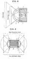
- FIG. 5an example of the angle ⁇ of the center axis of the light emitter device 5 in the radial direction with respect to the center axis of the objective lens 4 is shown together with light distributions in that case.
- Fig. 6is illustrative of light distributions for one example of a spherical form of light emitter device used here.
- the angle with respect to the center axis at which there is a 10% intensity with respect to the intensity of light given out in the direction of the center axis of the light emitter device in the radial directionis 80°.
- Fig. 7is illustrative in schematic of the inventive capsule endoscope 10 with which that light emitter device 5 is used.
- a longitudinal distance N between the centers of light emitter devices 5 located ahead and behindis 10 mm; a longitudinal distance M between the centers of the ends of objective lenses 4 located ahead and behind is 11 mm; an angle ⁇ with respect to the center axis at which there is a 10% intensity with respect to the intensity of light given out in the direction of the center axis of the light emitter device 5 in the radial direction is 80°; an angle ⁇ that the center axis of the light emitter device 5 in the radial direction makes with the center axis of the objective lens 4 is 35°; and a half ⁇ the angle of field of the objective lens 4 is 110°.
- the light given out of the light emitter-device 5 falling within the field of viewis supposed to have an intensity of 10% or greater; even when the objective lens has a wide-angle field, a bright image can be viewed as far as its periphery.
Landscapes
- Health & Medical Sciences (AREA)
- Life Sciences & Earth Sciences (AREA)
- Surgery (AREA)
- Biomedical Technology (AREA)
- Medical Informatics (AREA)
- Optics & Photonics (AREA)
- Pathology (AREA)
- Radiology & Medical Imaging (AREA)
- Biophysics (AREA)
- Engineering & Computer Science (AREA)
- Physics & Mathematics (AREA)
- Heart & Thoracic Surgery (AREA)
- Nuclear Medicine, Radiotherapy & Molecular Imaging (AREA)
- Molecular Biology (AREA)
- Animal Behavior & Ethology (AREA)
- General Health & Medical Sciences (AREA)
- Public Health (AREA)
- Veterinary Medicine (AREA)
- Endoscopes (AREA)
- Instruments For Viewing The Inside Of Hollow Bodies (AREA)
- Measurement Of The Respiration, Hearing Ability, Form, And Blood Characteristics Of Living Organisms (AREA)
Abstract
Description
- The present invention relates generally to a capsule endoscope, and more particularly to an optimum structure for wide-field observation by capsule endoscopes.
- Unlike conventional endoscopes, current capsule endoscopes have not a function of implementing in-vivo scans in any desired field direction; as compared with an endoscope having the same field range, a capsule endoscope would have a blind spot in a range incapable of changing the field of view, resulting in an increased probability of some oversight of lesions.
- For this reason, the capsule endoscope having no function of implementing scans over the field range is designed to have a wide-angle, ahead-and-behind binocular imaging system (Patent Publication 1) so that any blind spot can be eliminated to stave off the oversight of lesions; the binocular imaging system is said to be a function of urgent need.
- However, making the optical system a wide-angle arrangement leads to use of a number of lenses, resulting in total length increases and cost rises; there is a mounting demand toward achieving that wide-angle arrangement with as much reduced lens counts as possible (Patent Publication 2).
- When a similar illumination system as used heretofore is employed while the range of field of an objective system is just widened, the range of field widened by the wide-angle arrangement is less brightly illuminated, possibly ending up with a drop of the rate of spotting lesions.
- To take advantage of improvements in the performance due to the wide-angle arrangement for the imaging system, it is simultaneously necessary to distribute illumination light over a wider range (
Patent Publications 3 and 4). Patent Publication 1
Published Translation 2005-503182Patent Publication 2JP(A)2005-80713 Patent Publication 3
Internal PublicationWO2004/096029 Patent Publication 4JP(A)2004-275542
In view of such situations with the prior art as described, the present invention has for its object to provide a capsule endoscope layout capable of achieving a small-format, wide-angle, wide light-distribution arrangement with limited variations.- According to the invention, the aforesaid object is accomplishable by the provision of a capsule endoscope which comprises an objective lens, a transparent dome to cover the object side of said objective lens, and light emitter devices located around the outer periphery of said objective lens, characterized by comprising an integral-piece holder member adapted to hold said objective lens in place and hold said light emitter device at a position set back from the end of, and around, said objective lens while said light emitter devices are inclined outward at an angle with the center axis of said objective lens.
- Preferably in this case, the aforesaid holder member has a conical or pyramidal surface with an opening in a central portion thereof that is of the same shape as an external shape of said objective lens and an opening in a side thereof that is of the same shape as an external shape of each light emitting device, wherein said objective lens and each light emitter device are fitted and positioned in said openings.
- That is, to incline the angle of the light emitter devices located, they are attached to a flexible substrate; without any holder structure, however, the location of the light emitter devices would get erratic. Unless the angle of inclination is kept with high precision, there would be variations in the distributed light, and flares as well. By use of the integral-piece holder member, the light emitter devices attached to the flexible substrate remain fixed with more reliable alignment of the objective lens with the light emitter devices so that there can be less variations in the distributed light, and less unwanted light.
- If the objective lens is held by the integral-piece holder member, a portion with the light emitter devices attached to it is tapered to make the distributed light wide and the objective lens is located at the center of the endoscope, there is none of field shadings at the light emitter devices around the objective lens and at the portion with the light emitter device attached to it even when the objective lens has a wide angle of 180° or greater. Jutting out the objective lens in the transparent dome permits the objective lens to be located within the dome so that the total endoscope length can be curtailed at the same time.
- The invention also provides a capsule endoscope which comprises an objective lens, a transparent dome to cover the object side of said objective lens, and light emitter devices located around the outer periphery of said objective lens, characterized in that:
there are two objective lenses provided ahead and behind, there is a transparent dome provided to cover the object sides of said objective lenses, there are light emitter devices provided around the outer peripheries of said objective lenses, and the light emitter devices provided ahead and behind are located at a position set back from the end of each object lens and inclined outward with respect to the center axis of each objective lens so that light distributed from the light emitter devices located ahead and behind intersects ahead and behind and around them. - To locate two wide-angle objective optical systems ahead and behind into a binocular arrangement for viewing images all around, the light emitter devices located ahead and behind should be such that the distributed light intersects ahead and behind and around them, thereby getting rid of portions that illumination light does not arrive at.
- Preferably in the invention, the aforesaid objective lens has a field range of 140° or greater and satisfies the following condition (1):

where θ is an angle that the center axis of each light emitter device in the radial direction makes with the center axis of the objective lens. - Preferably in the invention, the aforesaid objective lens has a three lenses arrangement comprising, in order from its object side, a meniscus lens having negative refracting power and convex on its object side, a lens having negative refracting power, a stop and a lens having positive refracting power.
- The aforesaid light emitter device may be made up of a light emitting diode (LED), and an electroluminescent device (EL).
- The former is bright and less costly. Attached to the flexible substrate, the latter is thin and may be attached even in narrow space, and is of fast response as well.
- It is also desired to satisfy the following condition (2):

where Ra is the radius of curvature of said object lens surface on the aforesaid transparent dome side, and L is the distance of the apex of the aforesaid objective lens surface on the aforesaid transparent dome side to the surface of the aforesaid objective lens nearest to the object side. - Thus, even when the objective lens makes its way into the transparent dome by way of a wide-angle objective system, the narrowing of the field does not occur so that the length of the whole capsule endoscope can be curtailed, making much contribution to easing off burdens on patients.
- Further, the invention provides a capsule endoscope wherein the aforesaid light emitter devices are located such that when light is emitted out of each light emitter device onto a spherical object, light emitted out of the light emitter devices located ahead and behind and having an intensity of 10% or greater intersects assumed that the intensity of light emitted in the direction of the center axis of each light emitter device in the radial direction is 100%.
- Yet further, the invention provides a capsule endoscope that satisfies the following condition (3):

where N is a longitudinal distance between the centers of the light emitter devices located ahead and behind; M is a longitudinal distance between the centers of the ends of the objective lenses located ahead and behind; α is an angle with respect to the center axis at which there is a 10% intensity with respect to the intensity of light given out in the direction of the center axis of the light emitter device in the radial direction; β is a half the angle of field of the objective lenses; and θ is an angle that the center axes of the light emitter devices in the radial direction make with the center axes of the objective lenses. - According to the invention, the objective lenses are configured into a wide-angle arrangement, and the application of this arrangement to an illumination system layout for a conventional capsule endoscope would render the brightness of its periphery to be less sufficient, working against observations. However, the light emitter devices are inclined and located around the optical system so that it is possible to achieve a wide light-distribution illumination system compatible even with a wide-angle optical system, resulting in improvements in screening capability due to a wide-angle-of-field, wide light-distribution arrangement.
- By locating two objective lenses each having an angle of field of 140° or greater in the ahead-and-behind direction to set up a binocular arrangement capable of viewing images nearly all around, it is possible to make substantial elimination of any blind spot. It is thus possible to get rid of blind spots even with a capsule endoscope having no function of changing the field direction freely and, hence, make improvements in screening capability.
- Still other objects and advantages of the invention will in part be obvious and will in part be apparent from the specification.
- The invention accordingly comprises the features of construction, combinations of elements, and arrangement of parts which will be exemplified in the construction hereinafter set forth, and the scope of the invention will be indicated in the claims.
Fig. 1 is illustrative in section of the construction of an end of the inventive capsule endoscope.Fig. 2 is illustrative in section of a binocular type capsule endoscope wherein such end structures as shown inFig. 1 are located ahead and behind.Fig. 3 is illustrative in schematic of how the small intestine is observed and diagnosed inside by the capsule endoscope ofFig. 2 .Fig. 4(a) is illustrative in section of one exemplary construction of an end of the inventive capsule endoscope andFig. 4(b) is a front view of the holder frame.Fig. 5 is illustrative of one exemplary angle that the center axis of the light emitter device in the radial direction makes with the center axis of the objective lens, and how light is distributed then.Fig. 6 is illustrative of how light is distributed from one exemplary light emitter device.Fig. 7 is illustrative in schematic of the inventive capsule endoscope using the light emitter device ofFig. 6 .Fig. 8 is illustrative in section of an end structure of a prior art capsule endoscope.Fig. 9 is illustrative in section of a prior art binocular type capsule endoscope.- Examples of the inventive capsule endoscope are now explained with reference to the accompanying drawings.
- Referring to
Fig. 8 that is illustrative of an end structure of aconventional capsule endoscope 1, a transparent,semispherical dome 2 is located over the end of thecapsule endoscope 1; within thecapsule endoscope 1 there is anobjective lens 4 attached to the center of aframe member 3; and at a planar end of theframe member 3 around theobjective lens 4 there are a plurality oflight emitter devices 5 located symmetrically about the center axis, wherein each light emitter device comprises a light emitter diode (LED) or electroluminescent device (EL). In such arrangement, the field range (indicated by a broken line) of theobjective lens 4 is included in the illumination range (indicated by a solid line) of thelight emitter devices 5. - As end structures of such arrangement are located ahead and behind into a binocular
type capsule endoscope 10, it causes a non-illumination range (area) to appear between the illumination ranges of bothlight emitter devices 5; even when the field range (broken line) of eachobjective lens 4 is widened, that non-illumination range renders brightness insufficient, resulting a drop of the rate of spotting lesions. - In the invention, therefore, there is a
capsule endoscope 1 set up as shown inFig. 1 , wherein anend surface 31 of aframe member 3 around anobjective lens 4 is configured as a conical or pyramidal shape such that an end of the centrally locatedobjective lens 4 juts out in adome 2 and positions of a plurality oflight emitter devices 5 located around there are set back from an end of theobjective lens 4, and thelight emitter devices 5 are attached to that conical orpyramidal end surface 31 such that they direct outward obliquely with respect to the center axis of theobjective lens 4. The range of illumination by the symmetrically locatedlight emitter devices 5 grows wide and, with this, the field range of theobjective lens 4 grows wide, resulting in a wider field range. - The field range of the
objective lens 4 here is desirously 140° or greater. And in letting θ stand for an angle that the center axis of eachlight emitter device 5 in the radial direction makes with the center axis of theobjective lens 4, it is desirous to satisfy the following condition.
At the lower limit of 0° to condition (1), the same thing as in the prior art ofFig. 8 takes place: the endoscope runs short of illumination at off-axis sites with a drop of the rate of spotting lesions. As the upper limit of 60° is exceeded, on the contrary, the endoscope is likely to run short of illumination on the center axis. - Referring now to a binocular
type capsule endoscope 10 comprising such end structures as shown inFig. 1 located ahead and behind, the illumination ranges by a plurality oflight emitter devices 5 at the respective ends are set wider than 180° such that the ranges (illumination ranges) of light distributed from thelight emitter devices 5 located ahead and behind intersect mutually (of course, the ranges of light distributed from a plurality oflight emitter devices 5 located at the respective ends intersect mutually, too). This makes it possible to illuminate almost all around thecapsule endoscope 10 so that, as shown schematically shown inFig. 3 , for instance, the small intestine C can be observed and diagnosed with no blind spot yet with a very low probability of losing sight of lesions. Fig. 4(a) is illustrative in section of one exemplary construction of one end of thecapsule endoscope 1. At the end of acylindrical housing 15 of the capsule endoscope, there is aholder frame 30 fixed, whose front view is presented inFig. 4(b) , and over that, a transparent,semispherical dome 2 is covered to form the end of thecapsule endoscope 1. Theholder frame 30 is formed of a sheet metal of hexagonal pyramid shape having in the center of an apex surface anopening 32 into which anobjective lens 4 is fitted, and anopening 33 for fixing alight emitter device 5 is provided in one each side of the hexagonal pyramid. A lens barrel of theobjective lens 4 is coaxially fixed in theopening 32 in the apex surface of theholder frame 30 of hexagonal pyramid shape, and aflexible substrate 20 havinglight emitter devices 5 at a given interval on its front surface is pressed against and fixed to the inside surface (back surface) of theholder frame 30, so that one eachlight emitter device 5 is inserted through and fixed in theopening 33 in one each side of theholder frame 30 from within theholder frame 30.- As set forth typically in
Patent Publication 2, theobjective lens 4 is of a three lenses type that is made up of, in order from its object side, a meniscus lens L1 having negative refracting power and convex on its object side, a lens L2 having negative refracting power, a stop S and a lens L3 having positive refracting power, so that the angle of field to be viewed can be set to 140° or greater, and preferably 180° or greater with no blind spot, leading to much less chances of losing sight of lesions. And animaging device 21 such as CCD is located on the image plane of theobjective lens 4 for connection to theflexible substrate 20. - Thus, by application to the end structure of the
capsule endoscope 1 of theholder frame 30 capable of precisely determining the positions of location of theobjective lens 4 andlight emitter devices 5, it is possible to achieve a structure capable of holding the imaging system and the illumination system as an integral piece, thereby determining the location of theobjective lens 4 andlight emitter devices 5 with high precision. Thelight emitter devices 5 are mounted on theflexible substrate 20 that enables the directions of the devices to be freely determined, but without any holder structure, however, the location of thelight emitter devices 5 would get erratic, possibly causing variations in light distribution, and flares. However, if, as described above, the integral-piece holder frame 30 is used which allows thelight emitter devices 5 attached to theflexible substrate 20 to be fixed in place and the positions of theobjective lens 4 andlight emitter devices 5 to be determined with high precision, it is then possible to reduce the variations in light distribution and unwanted light, and improve assembly capabilities as well. - With the
inventive capsule endoscope 1, thelight emitter devices 5 are attached to the inclined sides of theholder frame 30 around theobjective lens 4; theobjective lens 4 is positioned jutting out in the transparentsemispherical dome 2. It is thus possible just only to achieve a wide-field, wide light-distribution arrangement but also to reduce dead space in thedome 2 and curtail the length of the whole of thecapsule endoscope 1 by the amount of jutting of theobjective lens 4 into thedome 2. A reduction in the total length of thecapsule endoscope 1 helps reduce burdens on patients and take hold of safety. To this end, it is desired to satisfy the following condition.
Here Ra is the radius of curvature of the surface of theobjective lens 4 on thetransparent dome 2 side, and L is the distance from the apex of the surface of theobjective lens 4 on thetransparent dome 2 side to the surface located in, and nearest to the object side of, the objective lens (the object-side surface of the meniscus lens L1). - Beyond of the range of condition (2), the aforesaid effect on reductions of the total length is not obtainable.
- Referring then to
Fig. 5 , an example of the angle θ of the center axis of thelight emitter device 5 in the radial direction with respect to the center axis of theobjective lens 4 is shown together with light distributions in that case. A reference light distribution for eachlight emitter device 5 is obtained at θ=0, and light distributions at angles of 0 to 90° with the center axis of theobjective lens 4 located at the angle θ of 15°, 30°, and 45° are drawn inFig. 5 . At the angle of location θ=45°, even the periphery of theobjective lens 4 at 90° with respect to the center axis of theobjective lens 4 is going to be brightly illuminated. Fig. 6 is illustrative of light distributions for one example of a spherical form of light emitter device used here. The angle with respect to the center axis at which there is a 10% intensity with respect to the intensity of light given out in the direction of the center axis of the light emitter device in the radial direction is 80°.Fig. 7 is illustrative in schematic of theinventive capsule endoscope 10 with which thatlight emitter device 5 is used. A longitudinal distance N between the centers oflight emitter devices 5 located ahead and behind is 10 mm; a longitudinal distance M between the centers of the ends ofobjective lenses 4 located ahead and behind is 11 mm; an angle α with respect to the center axis at which there is a 10% intensity with respect to the intensity of light given out in the direction of the center axis of thelight emitter device 5 in the radial direction is 80°; an angle θ that the center axis of thelight emitter device 5 in the radial direction makes with the center axis of theobjective lens 4 is 35°; and a half β the angle of field of theobjective lens 4 is 110°. That is,

of which (N/2)/tan(β-90° )=13.7 is larger.
- By satisfying condition (3), the light given out of the light emitter-
device 5 falling within the field of view is supposed to have an intensity of 10% or greater; even when the objective lens has a wide-angle field, a bright image can be viewed as far as its periphery. - While the inventive capsule endoscope has been described with reference to its examples, it is appreciated that the invention is never limited to them: various modifications may be achievable.


Claims (15)
- A capsule endoscope which comprises an objective lens, a transparent dome to cover an object side of said objective lens, and light emitter devices located around an outer periphery of said objective lens,characterized by comprising an integral-piece holder member adapted to hold said objective lens in place and hold said light emitter devices at a position set back from an end of, and around, said objective lens while said light emitter devices are inclined outward at an angle with a center axis of said objective lens.
- The capsule endoscope according to claim 1,characterized in that said holder member has a conical or pyramidal surface with an opening in a central portion thereof that is of the same shape as an external shape of said objective lens and an opening in a side thereof that is of the same shape as an external shape of each light emitting device, wherein said objective lens and each light emitter device are fitted and positioned in said openings.
- A capsule endoscope which comprises an objective lens, a transparent dome to cover the object side of said objective lens, and light emitter devices located around the outer periphery of said objective lens,characterized in that:there are two objective lenses provided ahead and behind, there is a transparent dome provided to the object sides of said objective lenses, there are light emitter devices provided around the outer peripheries of said objective lenses, and the light emitter devices located ahead and behind are located at a position set back from the end of each object lens and inclined outward with respect to the center axis of each objective lens so that light distributed from the light emitter devices located ahead and behind intersects ahead and behind and around them.
- The capsule endoscope according to claim 1, wherein said objective lens has a field range of 140° or greater and satisfies the following condition (1):

where θ is an angle that a center axis of each light emitter device in a radial direction makes with a center axis of the objective lens. - The capsule endoscope according to claim 4, wherein each objective lens comprises a three lenses arrangement comprising, in order from an object side thereof, a meniscus lens having negative refracting power and convex on an object side thereof, a lens having negative refracting power, a stop and a lens having positive refracting power.
- The capsule endoscope according to claim 3, wherein each objective lens has a field range of 140° or greater and satisfies the following condition (1):

where θ is an angle that a center axis of each light emitter device in a radial direction makes with a center axis of each objective lens. - The capsule endoscope according to claim 6, wherein each objective lens comprises a three lenses arrangement comprising, in order from an object side thereof, a meniscus lens having negative refracting power and convex on an object side thereof, a lens having negative refracting power, a stop and a lens having positive refracting power.
- The capsule endoscope according to claim 1,characterized in that each light emitter device comprises a light-emitting diode (LED).
- The capsule endoscope according to claim 3,characterized in that each light emitter device comprises a light-emitting diode (LED).
- The capsule endoscope according to claim 1,characterized in that each light emitter device comprises an electroluminescent device (EL).
- The capsule endoscope according to claim 3,characterized in that each light emitter device comprises an electroluminescent device (EL).
- The capsule endoscope according to claim 1,characterized by satisfying the following condition (2):

where Ra is a radius of curvature of an object lens surface covered by said transparent dome, and L is a distance of an apex of said objective lens surface covered by said transparent dome to a surface of said objective lens nearest to an object side thereof. - The capsule endoscope according to claim 3,characterized by satisfying the following condition (2):

where Ra is a radius of curvature of an object lens surface covered by said transparent dome, and L is a distance of an apex of said objective lens surface covered by said transparent dome to a surface of said objective lens nearest to an object side thereof. - The capsule endoscope according to claim 3,characterized in that said light emitter devices are located such that when light is emitted out of each light emitter device onto a spherical object, light emitted out of the light emitter devices located ahead and behind and having an intensity of 10% or greater intersects assumed that the intensity of light emitted in the direction of the center axis of each light emitter device in the radial direction is 100%.
- The capsule endoscope according to claim 3,characterized by satisfying the following condition (3):

where N is a longitudinal distance between the centers of the light emitter devices located ahead and behind; M is a longitudinal distance between the centers of the ends of the objective lenses located ahead and behind; α is an angle with respect to the center axis at which there is a 10% intensity with respect to the intensity of light given out in the direction of the center axis of the light emitter device in the radial direction; β is a half the angle of field of the objective lenses; and θ is an angle that the center axes of the light emitter devices in the radial direction make with the center axes of the objective lenses.


Applications Claiming Priority (1)
| Application Number | Priority Date | Filing Date | Title |
|---|---|---|---|
| JP2007231362AJP2009061097A (en) | 2007-09-06 | 2007-09-06 | Capsule endoscope |
Publications (2)
| Publication Number | Publication Date |
|---|---|
| EP2033570A1true EP2033570A1 (en) | 2009-03-11 |
| EP2033570B1 EP2033570B1 (en) | 2013-04-24 |
Family
ID=40028975
Family Applications (1)
| Application Number | Title | Priority Date | Filing Date |
|---|---|---|---|
| EP08010175.1ANot-in-forceEP2033570B1 (en) | 2007-09-06 | 2008-06-04 | Capsule endoscope |
Country Status (4)
| Country | Link |
|---|---|
| US (1) | US20090069633A1 (en) |
| EP (1) | EP2033570B1 (en) |
| JP (1) | JP2009061097A (en) |
| CN (1) | CN101380219B (en) |
Cited By (3)
| Publication number | Priority date | Publication date | Assignee | Title |
|---|---|---|---|---|
| CN102362208A (en)* | 2009-03-24 | 2012-02-22 | 富士胶片株式会社 | capsule endoscope |
| CN110392545A (en)* | 2017-04-03 | 2019-10-29 | Hoya株式会社 | Endoscope with wide-angle lens and service aisle |
| CN118216863A (en)* | 2024-05-24 | 2024-06-21 | 北京大学第三医院(北京大学第三临床医学院) | A compact wide-angle surgical endoscope based on observing three-dimensional spatial depth representation |
Families Citing this family (20)
| Publication number | Priority date | Publication date | Assignee | Title |
|---|---|---|---|---|
| TWI539925B (en)* | 2011-01-18 | 2016-07-01 | Medical Intubation Tech Corp | An endoscopic image pickup assembly having two or more illumination directions |
| US20120229426A1 (en)* | 2011-03-09 | 2012-09-13 | Avermedia Information, Inc. | Pen-shaped input apparatus |
| CN102305966B (en)* | 2011-05-16 | 2014-07-02 | 深圳市资福技术有限公司 | Capsule endoscopy |
| US9071740B1 (en) | 2011-10-28 | 2015-06-30 | Google Inc. | Modular camera system |
| US9197686B1 (en) | 2012-01-06 | 2015-11-24 | Google Inc. | Backfill of video stream |
| US10178211B2 (en)* | 2013-06-06 | 2019-01-08 | Dolby Laboratories Licensing Corporation | Lighting for audio devices |
| WO2016103446A1 (en)* | 2014-12-26 | 2016-06-30 | オリンパス株式会社 | Optical system and capsule endoscope |
| US9544485B2 (en) | 2015-05-27 | 2017-01-10 | Google Inc. | Multi-mode LED illumination system |
| US9235899B1 (en) | 2015-06-12 | 2016-01-12 | Google Inc. | Simulating an infrared emitter array in a video monitoring camera to construct a lookup table for depth determination |
| US9886620B2 (en) | 2015-06-12 | 2018-02-06 | Google Llc | Using a scene illuminating infrared emitter array in a video monitoring camera to estimate the position of the camera |
| US9554063B2 (en) | 2015-06-12 | 2017-01-24 | Google Inc. | Using infrared images of a monitored scene to identify windows |
| US9386230B1 (en) | 2015-06-12 | 2016-07-05 | Google Inc. | Day and night detection based on one or more of illuminant detection, lux level detection, and tiling |
| US9454820B1 (en) | 2015-06-12 | 2016-09-27 | Google Inc. | Using a scene illuminating infrared emitter array in a video monitoring camera for depth determination |
| CN105769111A (en)* | 2016-02-29 | 2016-07-20 | 吉林大学 | Wide-angle double-camera capsule endoscopy |
| US10180615B2 (en) | 2016-10-31 | 2019-01-15 | Google Llc | Electrochromic filtering in a camera |
| CN108508590A (en)* | 2018-04-19 | 2018-09-07 | 深圳市都乐精密制造有限公司 | Wide-angle capsule lens are peeped in medical |
| CA3166610A1 (en)* | 2020-01-31 | 2021-08-05 | Masoud TAHGHIGHI JAFARZADEH | An ingestible therapeutic device for the treatment of gastritis |
| CN113907692B (en)* | 2020-07-10 | 2024-12-24 | 紫东信息科技(苏州)有限公司 | Capsule endoscope |
| DE102020122636A1 (en)* | 2020-08-31 | 2022-03-03 | Hoya Corporation | Lighting device for an endoscope |
| TWI761974B (en)* | 2020-09-29 | 2022-04-21 | 醫電鼎眾股份有限公司 | Modular combination of endoscope light source and imaging module |
Citations (8)
| Publication number | Priority date | Publication date | Assignee | Title |
|---|---|---|---|---|
| US6261226B1 (en)* | 1994-03-30 | 2001-07-17 | Medical Media Systems | Electronically Steerable Endoscope |
| WO2001050941A2 (en)* | 2000-01-13 | 2001-07-19 | Capsule View Inc. | Encapsulated medical imaging device and method |
| JP2004275542A (en) | 2003-03-17 | 2004-10-07 | Olympus Corp | Capsule type endoscope |
| WO2004096029A1 (en) | 2003-04-25 | 2004-11-11 | Olympus Corporation | Capsule endoscope and capsule endoscope system |
| JP2005080713A (en) | 2003-09-04 | 2005-03-31 | Olympus Corp | Capsule type endoscope |
| US20060170328A1 (en)* | 2005-01-18 | 2006-08-03 | Pentax Corporation | Capsule endoscope |
| US20070055105A1 (en)* | 2003-09-01 | 2007-03-08 | Hirohiko Matsuzawa | Capsule type endoscope |
| EP1790280A1 (en)* | 2005-11-23 | 2007-05-30 | Given Imaging Limited | Method of assembling an in-vivo imaging device |
Family Cites Families (12)
| Publication number | Priority date | Publication date | Assignee | Title |
|---|---|---|---|---|
| US20020109774A1 (en)* | 2001-01-16 | 2002-08-15 | Gavriel Meron | System and method for wide field imaging of body lumens |
| JP2003260025A (en)* | 2002-03-08 | 2003-09-16 | Olympus Optical Co Ltd | Capsule endoscope |
| JP4363843B2 (en)* | 2002-03-08 | 2009-11-11 | オリンパス株式会社 | Capsule endoscope |
| WO2004028335A2 (en)* | 2002-09-30 | 2004-04-08 | Given Imaging Ltd. | In-vivo sensing system |
| WO2004096008A2 (en)* | 2003-05-01 | 2004-11-11 | Given Imaging Ltd. | Panoramic field of view imaging device |
| JP2005074031A (en)* | 2003-09-01 | 2005-03-24 | Pentax Corp | Capsule endoscope |
| JP4554267B2 (en)* | 2004-04-27 | 2010-09-29 | オリンパス株式会社 | Endoscope and endoscope system |
| US20060015013A1 (en)* | 2004-06-30 | 2006-01-19 | Zvika Gilad | Device and method for in vivo illumination |
| JP4980212B2 (en)* | 2004-06-30 | 2012-07-18 | ギブン イメージング リミテッド | In vivo imaging apparatus and method of assembling the same |
| US20060217593A1 (en)* | 2005-03-24 | 2006-09-28 | Zvika Gilad | Device, system and method of panoramic multiple field of view imaging |
| JP4767618B2 (en)* | 2005-08-09 | 2011-09-07 | オリンパスメディカルシステムズ株式会社 | In vivo information acquisition device |
| JP5006596B2 (en)* | 2006-08-21 | 2012-08-22 | オリンパスメディカルシステムズ株式会社 | Capsule endoscope |
- 2007
- 2007-09-06JPJP2007231362Apatent/JP2009061097A/enactivePending
- 2008
- 2008-06-04EPEP08010175.1Apatent/EP2033570B1/ennot_activeNot-in-force
- 2008-08-15USUS12/228,825patent/US20090069633A1/ennot_activeAbandoned
- 2008-08-21CNCN200810147212.7Apatent/CN101380219B/ennot_activeExpired - Fee Related
Patent Citations (8)
| Publication number | Priority date | Publication date | Assignee | Title |
|---|---|---|---|---|
| US6261226B1 (en)* | 1994-03-30 | 2001-07-17 | Medical Media Systems | Electronically Steerable Endoscope |
| WO2001050941A2 (en)* | 2000-01-13 | 2001-07-19 | Capsule View Inc. | Encapsulated medical imaging device and method |
| JP2004275542A (en) | 2003-03-17 | 2004-10-07 | Olympus Corp | Capsule type endoscope |
| WO2004096029A1 (en) | 2003-04-25 | 2004-11-11 | Olympus Corporation | Capsule endoscope and capsule endoscope system |
| US20070055105A1 (en)* | 2003-09-01 | 2007-03-08 | Hirohiko Matsuzawa | Capsule type endoscope |
| JP2005080713A (en) | 2003-09-04 | 2005-03-31 | Olympus Corp | Capsule type endoscope |
| US20060170328A1 (en)* | 2005-01-18 | 2006-08-03 | Pentax Corporation | Capsule endoscope |
| EP1790280A1 (en)* | 2005-11-23 | 2007-05-30 | Given Imaging Limited | Method of assembling an in-vivo imaging device |
Cited By (6)
| Publication number | Priority date | Publication date | Assignee | Title |
|---|---|---|---|---|
| CN102362208A (en)* | 2009-03-24 | 2012-02-22 | 富士胶片株式会社 | capsule endoscope |
| US8526112B2 (en) | 2009-03-24 | 2013-09-03 | Fujifilm Corporation | Capsule endoscope |
| CN102362208B (en)* | 2009-03-24 | 2014-06-04 | 富士胶片株式会社 | capsule endoscope |
| CN110392545A (en)* | 2017-04-03 | 2019-10-29 | Hoya株式会社 | Endoscope with wide-angle lens and service aisle |
| US11612304B2 (en) | 2017-04-03 | 2023-03-28 | Hoya Corporation | Endoscope having a wide-angle lens and a working channel |
| CN118216863A (en)* | 2024-05-24 | 2024-06-21 | 北京大学第三医院(北京大学第三临床医学院) | A compact wide-angle surgical endoscope based on observing three-dimensional spatial depth representation |
Also Published As
| Publication number | Publication date |
|---|---|
| EP2033570B1 (en) | 2013-04-24 |
| US20090069633A1 (en) | 2009-03-12 |
| CN101380219B (en) | 2012-10-10 |
| CN101380219A (en) | 2009-03-11 |
| JP2009061097A (en) | 2009-03-26 |
Similar Documents
| Publication | Publication Date | Title |
|---|---|---|
| EP2033570B1 (en) | Capsule endoscope | |
| CN103313644B (en) | Endoscope and endoscope-use illuminator | |
| US5448319A (en) | Optical system for monitor cameras to be mounted on vehicles | |
| US8579450B2 (en) | Sighting device containing an elongated body made from light conducting or light collecting material and coaxially disposed with a light source | |
| US6206825B1 (en) | Illumination system for endoscopes and an endoscope having the illumination system | |
| KR102082967B1 (en) | Head-up display device and illumination unit for head-up display device | |
| RU2626966C2 (en) | Device for displaying internal surface of hollow space in product | |
| US7507003B2 (en) | Light collective optical system | |
| EP2453284B1 (en) | Microscope | |
| US10130245B2 (en) | Endoscope apparatus | |
| JP2018180422A (en) | Imaging apparatus | |
| JP2020526234A (en) | Micro endoscope structure | |
| US6424470B1 (en) | Panoramic refracting optic | |
| CN105892036A (en) | Head-mounted monocular wide-angle low-illumination-level CMOS night-vision device | |
| EP2280302A3 (en) | Imaging lens and imaging apparatus | |
| JPWO2019111360A1 (en) | Endoscope | |
| JPWO2011155292A1 (en) | Light source device and endoscope system | |
| US4214371A (en) | Device for illuminating reticles in optical instruments | |
| CA2809270C (en) | Indicator systems in night vision devices | |
| EP2667235A1 (en) | Endoscope illumination optical system | |
| CN120265939A (en) | Protective covers for optical equipment | |
| CN113613544B (en) | Endoscope with a lens | |
| JP2012086029A (en) | Capsule endoscope | |
| US11378792B2 (en) | Optical system for microscope, and microscope in which same is used | |
| KR102775124B1 (en) | Optical instrument |
Legal Events
| Date | Code | Title | Description |
|---|---|---|---|
| PUAI | Public reference made under article 153(3) epc to a published international application that has entered the european phase | Free format text:ORIGINAL CODE: 0009012 | |
| AK | Designated contracting states | Kind code of ref document:A1 Designated state(s):AT BE BG CH CY CZ DE DK EE ES FI FR GB GR HR HU IE IS IT LI LT LU LV MC MT NL NO PL PT RO SE SI SK TR | |
| AX | Request for extension of the european patent | Extension state:AL BA MK RS | |
| 17P | Request for examination filed | Effective date:20090803 | |
| 17Q | First examination report despatched | Effective date:20090903 | |
| AKX | Designation fees paid | Designated state(s):DE FR GB | |
| GRAP | Despatch of communication of intention to grant a patent | Free format text:ORIGINAL CODE: EPIDOSNIGR1 | |
| RIN1 | Information on inventor provided before grant (corrected) | Inventor name:FUKUHORI, HITOSHI Inventor name:ORIHARA, TATSUYA | |
| GRAS | Grant fee paid | Free format text:ORIGINAL CODE: EPIDOSNIGR3 | |
| GRAA | (expected) grant | Free format text:ORIGINAL CODE: 0009210 | |
| AK | Designated contracting states | Kind code of ref document:B1 Designated state(s):DE FR GB | |
| REG | Reference to a national code | Ref country code:GB Ref legal event code:FG4D | |
| REG | Reference to a national code | Ref country code:DE Ref legal event code:R096 Ref document number:602008023994 Country of ref document:DE Effective date:20130627 | |
| PLBE | No opposition filed within time limit | Free format text:ORIGINAL CODE: 0009261 | |
| STAA | Information on the status of an ep patent application or granted ep patent | Free format text:STATUS: NO OPPOSITION FILED WITHIN TIME LIMIT | |
| GBPC | Gb: european patent ceased through non-payment of renewal fee | Effective date:20130724 | |
| REG | Reference to a national code | Ref country code:FR Ref legal event code:ST Effective date:20140228 | |
| 26N | No opposition filed | Effective date:20140127 | |
| PG25 | Lapsed in a contracting state [announced via postgrant information from national office to epo] | Ref country code:GB Free format text:LAPSE BECAUSE OF NON-PAYMENT OF DUE FEES Effective date:20130724 | |
| REG | Reference to a national code | Ref country code:DE Ref legal event code:R097 Ref document number:602008023994 Country of ref document:DE Effective date:20140127 | |
| PG25 | Lapsed in a contracting state [announced via postgrant information from national office to epo] | Ref country code:FR Free format text:LAPSE BECAUSE OF NON-PAYMENT OF DUE FEES Effective date:20130701 | |
| REG | Reference to a national code | Ref country code:DE Ref legal event code:R082 Ref document number:602008023994 Country of ref document:DE Representative=s name:WUESTHOFF & WUESTHOFF, PATENTANWAELTE PARTG MB, DE Ref country code:DE Ref legal event code:R081 Ref document number:602008023994 Country of ref document:DE Owner name:OLYMPUS CORPORATION, JP Free format text:FORMER OWNER: OLYMPUS MEDICAL SYSTEMS CORP., TOKYO, JP | |
| PGFP | Annual fee paid to national office [announced via postgrant information from national office to epo] | Ref country code:DE Payment date:20170530 Year of fee payment:10 | |
| REG | Reference to a national code | Ref country code:DE Ref legal event code:R119 Ref document number:602008023994 Country of ref document:DE | |
| PG25 | Lapsed in a contracting state [announced via postgrant information from national office to epo] | Ref country code:DE Free format text:LAPSE BECAUSE OF NON-PAYMENT OF DUE FEES Effective date:20190101 |