EP2031326A2 - Cargo container for transporting temperature sensitive items - Google Patents
Cargo container for transporting temperature sensitive itemsDownload PDFInfo
- Publication number
- EP2031326A2 EP2031326A2EP08162815AEP08162815AEP2031326A2EP 2031326 A2EP2031326 A2EP 2031326A2EP 08162815 AEP08162815 AEP 08162815AEP 08162815 AEP08162815 AEP 08162815AEP 2031326 A2EP2031326 A2EP 2031326A2
- Authority
- EP
- European Patent Office
- Prior art keywords
- cargo container
- temperature
- outer shell
- smoke
- cargo
- Prior art date
- Legal status (The legal status is an assumption and is not a legal conclusion. Google has not performed a legal analysis and makes no representation as to the accuracy of the status listed.)
- Granted
Links
- 239000000779smokeSubstances0.000claimsabstractdescription41
- 238000005057refrigerationMethods0.000claimsabstractdescription15
- 239000003570airSubstances0.000claimsdescription34
- 239000012080ambient airSubstances0.000claimsdescription15
- 238000001514detection methodMethods0.000claimsdescription12
- 238000000034methodMethods0.000claimsdescription10
- 239000012774insulation materialSubstances0.000claimsdescription8
- 239000011148porous materialSubstances0.000claimsdescription5
- 238000004519manufacturing processMethods0.000claimsdescription3
- 238000009413insulationMethods0.000abstractdescription39
- 238000010438heat treatmentMethods0.000abstractdescription14
- XAGFODPZIPBFFR-UHFFFAOYSA-NaluminiumChemical compound[Al]XAGFODPZIPBFFR-UHFFFAOYSA-N0.000abstractdescription13
- 229910052782aluminiumInorganic materials0.000abstractdescription13
- 239000002131composite materialSubstances0.000abstractdescription13
- 239000002985plastic filmSubstances0.000abstractdescription4
- 229920006255plastic filmPolymers0.000abstractdescription2
- 239000000835fiberSubstances0.000description21
- 230000000712assemblyEffects0.000description12
- 238000000429assemblyMethods0.000description12
- 238000010276constructionMethods0.000description6
- 239000000463materialSubstances0.000description6
- 239000004033plasticSubstances0.000description6
- 229920003023plasticPolymers0.000description6
- 239000011347resinSubstances0.000description6
- 229920005989resinPolymers0.000description6
- 230000008901benefitEffects0.000description5
- 239000006260foamSubstances0.000description5
- 239000000853adhesiveSubstances0.000description3
- 230000001070adhesive effectEffects0.000description3
- 238000001816coolingMethods0.000description3
- 239000004794expanded polystyreneSubstances0.000description3
- 239000003733fiber-reinforced compositeSubstances0.000description3
- 229920006327polystyrene foamPolymers0.000description3
- 238000005192partitionMethods0.000description2
- 239000008280bloodSubstances0.000description1
- 210000004369bloodAnatomy0.000description1
- 238000010586diagramMethods0.000description1
- 229940079593drugDrugs0.000description1
- 239000003814drugSubstances0.000description1
- 230000009977dual effectEffects0.000description1
- 238000005265energy consumptionMethods0.000description1
- 230000007613environmental effectEffects0.000description1
- 239000003000extruded plasticSubstances0.000description1
- 239000004744fabricSubstances0.000description1
- 239000003063flame retardantSubstances0.000description1
- 230000002452interceptive effectEffects0.000description1
- 230000004048modificationEffects0.000description1
- 238000012986modificationMethods0.000description1
- 238000000465mouldingMethods0.000description1
- 230000002093peripheral effectEffects0.000description1
- 230000001681protective effectEffects0.000description1
- 230000003014reinforcing effectEffects0.000description1
- 238000000926separation methodMethods0.000description1
- 125000006850spacer groupChemical group0.000description1
- 238000003756stirringMethods0.000description1
- 238000001721transfer mouldingMethods0.000description1
- 229960005486vaccineDrugs0.000description1
- 238000009423ventilationMethods0.000description1
Images


Classifications
- F—MECHANICAL ENGINEERING; LIGHTING; HEATING; WEAPONS; BLASTING
- F25—REFRIGERATION OR COOLING; COMBINED HEATING AND REFRIGERATION SYSTEMS; HEAT PUMP SYSTEMS; MANUFACTURE OR STORAGE OF ICE; LIQUEFACTION SOLIDIFICATION OF GASES
- F25D—REFRIGERATORS; COLD ROOMS; ICE-BOXES; COOLING OR FREEZING APPARATUS NOT OTHERWISE PROVIDED FOR
- F25D11/00—Self-contained movable devices, e.g. domestic refrigerators
- F25D11/003—Transport containers
- F—MECHANICAL ENGINEERING; LIGHTING; HEATING; WEAPONS; BLASTING
- F25—REFRIGERATION OR COOLING; COMBINED HEATING AND REFRIGERATION SYSTEMS; HEAT PUMP SYSTEMS; MANUFACTURE OR STORAGE OF ICE; LIQUEFACTION SOLIDIFICATION OF GASES
- F25D—REFRIGERATORS; COLD ROOMS; ICE-BOXES; COOLING OR FREEZING APPARATUS NOT OTHERWISE PROVIDED FOR
- F25D17/00—Arrangements for circulating cooling fluids; Arrangements for circulating gas, e.g. air, within refrigerated spaces
- F25D17/04—Arrangements for circulating cooling fluids; Arrangements for circulating gas, e.g. air, within refrigerated spaces for circulating air, e.g. by convection
- F25D17/06—Arrangements for circulating cooling fluids; Arrangements for circulating gas, e.g. air, within refrigerated spaces for circulating air, e.g. by convection by forced circulation
- F—MECHANICAL ENGINEERING; LIGHTING; HEATING; WEAPONS; BLASTING
- F25—REFRIGERATION OR COOLING; COMBINED HEATING AND REFRIGERATION SYSTEMS; HEAT PUMP SYSTEMS; MANUFACTURE OR STORAGE OF ICE; LIQUEFACTION SOLIDIFICATION OF GASES
- F25D—REFRIGERATORS; COLD ROOMS; ICE-BOXES; COOLING OR FREEZING APPARATUS NOT OTHERWISE PROVIDED FOR
- F25D23/00—General constructional features
- F25D23/06—Walls
- F25D23/062—Walls defining a cabinet
- F25D23/063—Walls defining a cabinet formed by an assembly of panels
- F—MECHANICAL ENGINEERING; LIGHTING; HEATING; WEAPONS; BLASTING
- F25—REFRIGERATION OR COOLING; COMBINED HEATING AND REFRIGERATION SYSTEMS; HEAT PUMP SYSTEMS; MANUFACTURE OR STORAGE OF ICE; LIQUEFACTION SOLIDIFICATION OF GASES
- F25D—REFRIGERATORS; COLD ROOMS; ICE-BOXES; COOLING OR FREEZING APPARATUS NOT OTHERWISE PROVIDED FOR
- F25D23/00—General constructional features
- F25D23/06—Walls
- F25D23/065—Details
- F—MECHANICAL ENGINEERING; LIGHTING; HEATING; WEAPONS; BLASTING
- F25—REFRIGERATION OR COOLING; COMBINED HEATING AND REFRIGERATION SYSTEMS; HEAT PUMP SYSTEMS; MANUFACTURE OR STORAGE OF ICE; LIQUEFACTION SOLIDIFICATION OF GASES
- F25D—REFRIGERATORS; COLD ROOMS; ICE-BOXES; COOLING OR FREEZING APPARATUS NOT OTHERWISE PROVIDED FOR
- F25D2201/00—Insulation
- F25D2201/10—Insulation with respect to heat
- F25D2201/14—Insulation with respect to heat using subatmospheric pressure
- F—MECHANICAL ENGINEERING; LIGHTING; HEATING; WEAPONS; BLASTING
- F25—REFRIGERATION OR COOLING; COMBINED HEATING AND REFRIGERATION SYSTEMS; HEAT PUMP SYSTEMS; MANUFACTURE OR STORAGE OF ICE; LIQUEFACTION SOLIDIFICATION OF GASES
- F25D—REFRIGERATORS; COLD ROOMS; ICE-BOXES; COOLING OR FREEZING APPARATUS NOT OTHERWISE PROVIDED FOR
- F25D2317/00—Details or arrangements for circulating cooling fluids; Details or arrangements for circulating gas, e.g. air, within refrigerated spaces, not provided for in other groups of this subclass
- F25D2317/06—Details or arrangements for circulating cooling fluids; Details or arrangements for circulating gas, e.g. air, within refrigerated spaces, not provided for in other groups of this subclass with forced air circulation
- F25D2317/065—Details or arrangements for circulating cooling fluids; Details or arrangements for circulating gas, e.g. air, within refrigerated spaces, not provided for in other groups of this subclass with forced air circulation characterised by the air return
- F25D2317/0651—Details or arrangements for circulating cooling fluids; Details or arrangements for circulating gas, e.g. air, within refrigerated spaces, not provided for in other groups of this subclass with forced air circulation characterised by the air return through the bottom
- F—MECHANICAL ENGINEERING; LIGHTING; HEATING; WEAPONS; BLASTING
- F25—REFRIGERATION OR COOLING; COMBINED HEATING AND REFRIGERATION SYSTEMS; HEAT PUMP SYSTEMS; MANUFACTURE OR STORAGE OF ICE; LIQUEFACTION SOLIDIFICATION OF GASES
- F25D—REFRIGERATORS; COLD ROOMS; ICE-BOXES; COOLING OR FREEZING APPARATUS NOT OTHERWISE PROVIDED FOR
- F25D2317/00—Details or arrangements for circulating cooling fluids; Details or arrangements for circulating gas, e.g. air, within refrigerated spaces, not provided for in other groups of this subclass
- F25D2317/06—Details or arrangements for circulating cooling fluids; Details or arrangements for circulating gas, e.g. air, within refrigerated spaces, not provided for in other groups of this subclass with forced air circulation
- F25D2317/066—Details or arrangements for circulating cooling fluids; Details or arrangements for circulating gas, e.g. air, within refrigerated spaces, not provided for in other groups of this subclass with forced air circulation characterised by the air supply
- F25D2317/0665—Details or arrangements for circulating cooling fluids; Details or arrangements for circulating gas, e.g. air, within refrigerated spaces, not provided for in other groups of this subclass with forced air circulation characterised by the air supply from the top
- F—MECHANICAL ENGINEERING; LIGHTING; HEATING; WEAPONS; BLASTING
- F25—REFRIGERATION OR COOLING; COMBINED HEATING AND REFRIGERATION SYSTEMS; HEAT PUMP SYSTEMS; MANUFACTURE OR STORAGE OF ICE; LIQUEFACTION SOLIDIFICATION OF GASES
- F25D—REFRIGERATORS; COLD ROOMS; ICE-BOXES; COOLING OR FREEZING APPARATUS NOT OTHERWISE PROVIDED FOR
- F25D2317/00—Details or arrangements for circulating cooling fluids; Details or arrangements for circulating gas, e.g. air, within refrigerated spaces, not provided for in other groups of this subclass
- F25D2317/06—Details or arrangements for circulating cooling fluids; Details or arrangements for circulating gas, e.g. air, within refrigerated spaces, not provided for in other groups of this subclass with forced air circulation
- F25D2317/067—Details or arrangements for circulating cooling fluids; Details or arrangements for circulating gas, e.g. air, within refrigerated spaces, not provided for in other groups of this subclass with forced air circulation characterised by air ducts
- F—MECHANICAL ENGINEERING; LIGHTING; HEATING; WEAPONS; BLASTING
- F25—REFRIGERATION OR COOLING; COMBINED HEATING AND REFRIGERATION SYSTEMS; HEAT PUMP SYSTEMS; MANUFACTURE OR STORAGE OF ICE; LIQUEFACTION SOLIDIFICATION OF GASES
- F25D—REFRIGERATORS; COLD ROOMS; ICE-BOXES; COOLING OR FREEZING APPARATUS NOT OTHERWISE PROVIDED FOR
- F25D2700/00—Means for sensing or measuring; Sensors therefor
- F25D2700/12—Sensors measuring the inside temperature
- F25D2700/123—Sensors measuring the inside temperature more than one sensor measuring the inside temperature in a compartment
Definitions
- insulated containerswhich include heating and/or cooling means as disclosed, for example in U.S. Patents No. 5,483,799 and No. 5,603,220 and in U.S. Patents No. 5,950,450 and No. 5,943,876 assigned to the assignee of the present invention and the disclosures of which are herein incorporated by reference.
- a cargo containerwhich is adapted to receive a pallet supporting the temperature sensitive items and which also includes cooling and/or heating means for maintaining the temperature sensitive items within a close predetermined temperature range.
- Such cargo containersare disclosed, for example, in U.S.
- a Temperature-Controlled, Pallet-Sized Shipping Containeris also disclosed in U.S. patent application No. 2004/0226309, published November 18, 2004 , and the disclosure of which is herein incorporated by reference.
- This published applicationclaims the benefit of provisional application No. 60/447,987 filed February 17, 2003 by four co-inventors including co-inventors of the present invention, and the disclosure of which is herein incorporated by reference.
- any such cargo container adapted to receive one or more pallets of temperature sensitive itemsit is highly desirable for the container to have all walls and the doors with high thermal insulation or R value while minimizing the thickness of the walls in order to maximize the cargo space and minimize heat transfer to and from the container chamber. It is also desirable to provide efficient construction and assembly of the cargo container while providing substantial durability so that the cargo container has an extended service life. It is further desirable for temperature controlled air to be properly circulated within the cargo chamber in order to obtain a uniform temperature throughout the chamber. Preferably, the circulating air passes upwardly through a refrigeration evaporator and electrical heating elements and circulates along the walls of the container for precisely controlling the temperature within the cargo chamber.
- the cargo containerIn order for a cargo chamber to hold a narrow predetermined temperature range for an extended period of time, for example, over 72 hours, without an external power supply, it is necessary for the cargo container to carry storage batteries which may operate a refrigeration compressor or an electrical heating element through a control system which senses the temperature within the cargo chamber at predetermined locations.
- the heating element for the circulating airis sometimes desirable when the cargo container is being transported in a cold temperature zone or by an aircraft flying at a high altitude, and the container is exposed to very cold environmental air.
- the present inventionis directed to an improved cargo container assembly which provides all of the desirable features mentioned above including high thermal insulation with a relatively thin wall construction.
- the containermay also be efficiently produced and provides substantial durability and a high strength/weight ratio so that the container may be conveniently handled by forklift trucks without losing its high thermal insulation against heat transfer into and out of the container chamber which receives the cargo or items to be transported.
- a cargo containergenerally includes a rigid outer housing which may be a sheet aluminum shell or can having opposite side walls connected by a bottom wall, a rear wall and a removable top wall, and with a front or side opening normally closed by hinged door assemblies.
- a sub-assemblywhich includes a box-like molded composite outer shell having a front opening and enclosing a box-like molded composite inner shell also having a front opening.
- the corresponding side, top, bottom and rear walls of the inner and outer shellsconfine therebetween flat panel insulation cartridges or cassettes.
- Each cassetteincludes two or more layers of vacuum insulation panels which may be separated by a foam insulation sheet and sandwiched between protective plastic sheets, all of which are wrapped within a plastic film.
- a wall of the inner shellsupports a refrigeration evaporator, an electrical heating element and circulating fans, all protected by a composite inner wall panel which provides for air circulation within the cargo chamber through the evaporator and heating element.
- the corresponding wall of the outer shellhas a rectangular projection which supports a refrigeration compressor and storage batteries, and a control system senses the temperature within the chamber in different areas to operate the compressor and heating element from the batteries or an external power source in order to maintain a substantial constant preselected temperature within the chamber.
- a compartment of the housingencloses the compressor, storage batteries and control system which includes a plurality of smoke detectors for detecting smoke in the ambient air, and a plurality of ambient air temperature and humidity sensors, all for controlling the exhaust fans for the cargo container.
- the subject-matter of the present inventionis a cargo container assembly adapted to be delivered in an aircraft for transporting a temperature sensitive cargo supported by a pallet, said assembly comprising a box-like outer shell including side, top and bottom walls and having a front opening and a moveable door assembly for closing said front opening, a box-like inner shell within said outer shell and including side, top and bottom walls spaced inwardly from the corresponding said walls of said outer shell and defining a cargo receiving chamber, thermal insulation material confined between the corresponding said side, top and bottom walls of said inner and outer shells, a refrigeration system carried by said shells and connected to cool said chamber and including a compressor and at least one exhaust fan, a smoke detection system connected to control said exhaust fan, and said smoke detection system includes at least one smoke detector connected to de-energize said exhaust fan in response to the detection of smoke in the ambient air outside of said cargo container assembly.
- Said cargo container assemblycan include a plurality of said exhaust fans, and all of said exhaust fans can be connected to be de-energized in response to the detection of smoke by said smoke detector.
- Said cargo container assemblycan include a plurality of temperature and humidity sensors, and said exhaust fan can be connected to be de-energized in response to actuation of any one of said temperature and humidity sensors.
- Said smoke detection systemcan include a plurality of said smoke detectors.
- Said thermal insulation materialcan comprise vacuum insulated panels each including a core of porous material confined within an evacuated sealed bag of flexible gas impermeable film.
- Said outer shellcan form an outer housing for said cargo container assembly.
- Said cargo container assemblycan include at least one sensor for sensing temperature and humidity of the ambient air outside said outer shell, and a control system connected to de-energize said exhaust fan in response to said sensor sensing a predetermined temperature level and/or a humidity level of the ambient air outside of said cargo container assembly.
- Said cargo container assemblycan include a plurality of said exhaust fans and a plurality of said sensors, and all of said exhaust fans can be de-energized in response to any one of said sensors sensing said predetermined level of temperature and/or humidity.
- Said thermal insulation materialcan comprise vacuum insulated panels each including a core of porous material confined within an evacuated sealed bag of flexible gas impermeable film.
- Said outer shellcan form an outer housing for said cargo container assembly.
- the subject-matter of the present inventionis also a method of making a cargo container assembly adapted to be delivered in an aircraft for transporting a temperature sensitive cargo supported by a pallet, said method comprising the steps of:
- Said methodcan include the steps of:
- Said methodcan include the steps of:
- Said methodcan include the steps of:
- FIG. 1is a perspective view of a cargo container constructed in accordance with the invention and with the doors in their closed position;
- FIG. 2is a perspective view of the cargo container shown in FIG. 1 and with the doors shown in their open positions;
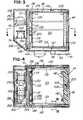
- FIG. 3is a vertical section through the cargo container, taken generally on the line 3-3 of FIG. 1 ;
- FIG. 4is a horizontal section of the container, taken generally on the line 4-4 of FIG. 3 ;
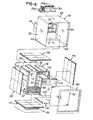
- FIG. 5is an exploded perspective view of a shell sub-assembly which is inserted into the outer housing assembly shown in FIG. 1 and which supports operating components;
- FIG. 6is an exploded perspective view of the shell sub-assembly before being inserted into the outer housing assembly
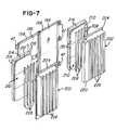
- FIG. 7is an exploded perspective view of the door assemblies shown in FIGS. 1 and 2 ;
- FIG. 8is an exploded view of an insulation cartridge or cassette used in the walls of the shell sub-assembly and in the door assembly, as shown in FIGS. 5 and 7 ;
- FIG. 9is a cross-section of an assembled insulation cassette shown exploded in FIG. 8 ;
- FIG. 10is a fragmentary corner section of the top wall and door assembly of the cargo container, taken generally on the line 10-10 of FIG. 1 ;
- FIG. 11is a fragmentary section of the overlapping closed door assemblies, taken generally on the line 11-11 of FIG. 1 ;
- FIG. 12is a fragmentary corner section of the shell sub-assembly, taken generally on the line 12-12 of FIG. 6 ;
- FIG. 13is a fragmentary section of the shell sub-assembly, taken generally on the line 13-13 of FIG. 6 ;
- FIG. 14is a fragmentary section of the shell sub-assembly, taken generally on the line 14-14 of FIG. 6 ;
- FIG. 15is a fragmentary section of the shell sub-assembly, taken generally on the line 15-15 of FIG. 6 ;
- FIG. 16is a fragmentary corner section of the shell sub-assembly, taken generally on the line 16-16 of FIG. 6 ;
- FIG. 17is a rear perspective view of a modified cargo container with the rear wall enclosure and storage batteries removed.
- FIG. 18is a block diagram of the electrical components and control system for the cargo container.
- a cargo container 25includes an outer housing 28 which is formed of sheet aluminum and aluminum corner trim and sometimes referred to as a "can".
- the housing 28includes opposite side walls 32, a removable top wall 34, a rear wall enclosure 36 and a bottom wall 38 ( FIG. 3 ).
- the housing 28is supported by a set of hollow aluminum supports or legs 41 connected by an aluminum base plate 42, and the spaced legs 41 are arranged to allow a two or three way entry under the cargo housing 28 with a forklift truck.
- the transporting of the container 25may be over the road (OTR) by trucks or rail or may be transported as a unit loading device (ULD) by a ship or aircraft.
- the housing 28also supports a pair of swinging door units or assemblies 44 and 46 ( FIGS. 1 & 2 ) each supported by a set of hinges 47 attached to the housing.
- the housing 28receives a shell sub-assembly 50 which includes a molded composite box-like outer shell 54 ( FIGS. 5 & 6 ) and a molded composite box-like inner shell 56, shown exploded in FIG. 5 .
- Each of the shells 54 and 56is molded as a one-piece unit, and the outer shell 54 includes a resin impregnated fiber reinforced outer skin 62 which forms opposite side walls 64 ( FIG. 5 ) integrally connected by a top wall 66 and a bottom wall 68 ( FIG. 5 ).
- the outer shell 54also has an integrally molded rear wall 72, and support walls 74 project rearwardly from the rear wall 72 of the outer shell 54, and are also formed of fiber reinforced composite plastic material and may be formed integrally with the rear wall 72 of the outer shell 54.
- the molded fiber reinforced side walls 64, rear wall 72, projecting support 74 and the bottom wall 68are also molded with fiber reinforced panels 82 and 83 ( FIG. 12 ) and 84 ( FIG. 3 ) which provide substantial additional strength and impact resistance to the outer shell 54.
- the fiber reinforced panels 82-84are formed from fiber reinforced core panels produced as disclosed in U.S. Patent No. 6,740,381 , the disclosure of which is herein incorporated by reference.
- the molding of the composite outer shell 54may be performed by vacuum assisted resin transfer molding (RTM) so that the resin penetrates the fibrous fabric forming the outer skin 62 of the shell 54 and also simultaneously penetrates the fibers within the fiber reinforced core panels 82-84 having inner skins and integral with the outer skin 62.
- RTMvacuum assisted resin transfer molding
- the shell sub-assembly 50also includes a composite box-like inner shell 56 ( FIG. 5 ) which is molded in the same manner as the outer shell 54 and includes a one-piece fiber reinforced inner skin 92 ( FIG. 5 ) which forms opposite side walls 94, a top wall 96, a rear wall 97 ( FIGS. 4 & 5 ) and a bottom wall 98 ( FIG. 12 ). All of the walls are integrally connected, and the rear wall 97 is provided with integrally molded co-planar step portions 102 ( FIG. 4 ).
- the side walls 94are molded with vertically spaced horizontal reinforcing ribs 106, and the lower portions of the side walls 94 and the bottom wall 98 are also molded with fiber reinforced core panels 108 and 110, respectively, which are resin impregnated with the inner skin 92 and formed in the same manner as the outer core panels 82 - 84.
- the fiber reinforced core panelshave a thickness of about 1 ⁇ 2 inch, and after the resin hardens, the reinforced panels provide the walls of the outer shell 54 and the lower portion of the inner shell 56 with substantial rigidity and impact strength, as described in above mentioned Patent No. 6,740,381.
- an aluminum or molded fiber reinforced partition or panel 114has an open top and open bottom and is attached to the rear wall 97 of the inner shell 56 to define an upward flow air passage 116 adjacent the rear wall 97.
- a molded fiber reinforced flat panel 120 having a fiber reinforced core as described above,is attached to the step portions 102 of the rear panel 97 and cooperates with the side walls 94, top wall 96 and bottom wall 98 of the inner shell 56 to define a cargo receiving chamber 125.
- the volume of the chamber 125may be on the order of 30 or 45 or 60 or 90 cubic feet, and is sufficiently large to receive a standard size pallet.
- the composite cold wall flat panel 120is vertically reinforced, for example, by having vertical fibrous webs in the fiber reinforced core to provide the panel 120 with additional strength.
- a series of laterally spaced channels 130are molded as part of the bottom wall 98 or are attached to the bottom wall 98 of the inner shell 56 by adhesive 132, and the channels 130 support a substantially flat aluminum floor panel or plate 135 having a thickness of about 1/8 inch.
- the floor plate 135( FIGS. 12 & 14 ) extends from the front opening of the inner shell 56 to the cold wall 120 to partition the inner cargo receiving chamber 125 from sub-floor air channels or passages 138.
- the sub-floor channels 130extend from the front opening of the inner shell 56 to its rear wall 97, to create the air return passages 138 under floor plate 135 together with the inner shell floor 98 ( FIG. 5 ).
- passagesconnect the return air flow from the bottom front of the inner shell 56 to the upward flow air passage 116 ( FIG. 3 ) for the evaporator/heater assembly.
- the sides of the floor plate 135are provided with upwardly facing tie-down seat channels 139 ( FIG. 4 ) for receiving straps or nets extending over the cargo.
- the forward edge portion of the floor plate 135has a series of parallel spaced slots 142 ( FIG. 4 ) which connect with the air flow passages 138. As shown in FIG. 3 , the rearward ends of the passages 138 are open and provide for air flow from the passages upwardly into the chamber 116 defined by the panel 114.
- each of the insulation cassettes 145-148includes a plurality of at least two panels or layers 152 each including a plurality of vacuum insulation panels 155.
- Each of the panels 155is constructed substantially as disclosed in U.S. Patent No. 6,623,413 assigned to the assignee of the present invention and the disclosure of which is herein incorporated by reference.
- each of the panels 155includes a core of porous material enclosed within a bag of gas impermeable film.
- each of the layers 152 of vacuum insulation panelshas a thickness of about 1 ⁇ 2 inch, and the layers are separated by a flat sheet 158 of plastic or expanded polystyrene foam and having a thickness of about 1/4 inch.
- the layers 152 of vacuum insulation panels 155are protected by and sandwiched between two outer sheets 162 of extruded plastic, for example, sold under the trademark "CoruPlast". All of the assembled layers 152 and sheets 158 and 162 are wrapped with a flexible film 164 of fire retardant plastics material.
- the thermal insulation panel assemblies 145-148are illustrated in the partial section views of FIGS. 10-16 as a one-piece insulation panel for simplification, but it is to be understood that each of the panels 145-148 is constructed substantially as described above in connection with FIGS. 8 and 9 .
- a set of fiber reinforced ribs 170are molded as an integral part of the inner shell 56 along the top and bottom and function as rigid spacers between the inner and outer shells.
- the inner fiber reinforced skin 42 of the inner shell 56is molded with an outwardly projecting return flange portion 172 which extends around the front end of the inner shell 56 and has a U-shaped cross-sectional configuration as shown in FIGS.
- the insulation cassettes 145 and 146have partial insulation panel extensions which project into the corner spaces between the shells. Additionally, similar insulation extensions project into sections where closed cell PVC expanded foam has been removed to reduce the heat shunts. This facilitates the connection of the insulation cassettes to each other, improving overall insulation coverage and reducing heat leaks. Closed cell PVC expanded foam 174 fills the space between the return flange 172 and the front edges of the insulation panels 145-147 and may be used in other voids within the container 25.
- a rectangular trim frame 180is molded of a plastics material such as ABS and has an L-shaped cross sectional configuration.
- the frame 180defines the front opening for the cargo container chamber 125 and is attached or bonded to the fiber reinforced skin of the inner shell 56 by strips 184 and 186 of adhesive.
- the front end portions of the skin of the inner shell 56may also be provided with interruptions to form thermal breaks for eliminating heat transfer through the skin.
- each of the door assemblies 44 and 46includes an outer aluminum sheet or panel 196 secured to a rectangular tubular aluminum frame 198 to which the hinges 47 are secured.
- the inner surfaces of the door assemblies 44 and 46are formed by panels 202 and 203, respectively, which are vacuum formed of a plastics material such as ABS and include an outwardly projecting peripheral flange 204 which is attached to the frame 198 of the door assembly by peripherally spaced screws or rivets.
- Each of the panels 202 and 203is formed with parallel spaced vertical channels 206, and a series of expanded foam strips 208 are attached to the inner surface of the panel between the channels 206 to provide a flush surface.
- each of the panels 202 and 203also encloses an insulation cassette 210 which is constructed substantially the same as the construction of the insulation cassettes 145-148 described above in connection with FIGS. 8-9 . That is, each of the insulation cassettes 210 includes two layers 212 of vacuum insulation panels 155 and the layers are separated by an expanded polystyrene foam sheet 214. Two panels 216 of expanded polystyrene foam are also located between the cassette 210 and the aluminum panel 196.
- the left hand door assembly 46includes an extension channel 220 which is vacuum formed from a sheet of plastics material such as ABS and is attached to the inner vacuum formed panel 202 of the door assembly. As shown in FIG. 11 , the extension channel 220 overlaps a step portion 222 of the panel 203 of the right hand door assembly 44. The extension channel 220 is filled by a lateral extension 224 of the inner layer 152 of the vacuum insulation panels 155 of the corresponding insulation cassette 210. The cassettes cooperate with the foam boards 216 to provide substantial thermal insulation for the door assemblies 44 and 46. As shown in FIG. 4 , the channels of the door panels 202 form air flow passages extending vertically directly above the slots 142 within the aluminum floor panel 135. As shown in FIG. 1 , a releasable latch mechanism 225 connects the door assemblies.
- a releasable latch mechanism 225connects the door assemblies.
- the composite panel 114 between the rear wall 97 of the inner shell 56 and the cold wall panel 120encloses an evaporator assembly 230 of a refrigeration system and also encloses an electrical heating coil or element 232.
- the impellers or fans of blowers 235operate to pull the air upwardly within the channel 116 and pass the heating element 232 and through the evaporator assembly 230.
- Insulation strips 236block air flow outside of passage 116.
- the blowersforce the cooled or heated air through an opening or space at the top of the portion 120 and forwardly along the top wall 96 of the inner shell 56 and within the chamber 125 to the front door assemblies 44 and 46 where the air flows downwardly along the inner surfaces of the door panels 202 and then through the slots 142 within the floor panel 135.
- the airthen flows rearwardly within the passages 138 below the floor panel and back into the bottom opening of the air flow passage 116.
- airis continuously circulated around the payload or cargo within the chamber 125.
- the channels 206provide air flow passages so that the air flow continues to flow downwardly along the door assemblies and into the slots 142 within the floor panel.
- a low power fanmay be used to stir the air in the chamber when the main blowers 235 are not operating.
- the upper wall of the rectangular rear projection or extension 74 molded as an integral part of the composite outer shell 54supports a motor driven refrigeration compressor 240 and condenser 242 having a housing supporting fans 244.
- the compressor and condenserare connected to the evaporator 230 by lines (not shown) extending through aligned holes within the rear wall 72 of the outer shell 54, the insulation cassette 148 and the rear wall 97 of the inner shell 56.
- the bottom wall of the extension 74supports rechargeable storage batteries 250 which provide an output of 12 or 24 volts DC to operate the refrigeration compressor 240, the heater element 232 and the blower fans 235.
- Tie down straps 252 and bolts 253secure the batteries positively to the bottom wall of the extension 74 of the outer shell 54.
- a set of upper and lower rectangular air vents 256are provided in the rear compartment or extension 36 of the outer housing 28 to provide convection ventilation within the housing portion.
- a side wall of the housing extension 36supports an exposed door covered control panel 260 of a controller 262 ( FIG. 4 ), and the housing extension 36 also encloses a battery charger 264 and a dual voltage power supply connector 266 for the battery charger for receiving an external power supply of 110 volts or 240 volts AC.
- the control panelalso encloses a universal AC voltage (100 - 240 VAC, 46 - 63 Hz) battery charger connector and a 12 - 28 V external DC power connector.
- the battery charger 264is mounted on the side wall of the rectangular projection 74 and is connected to the universal AC voltage connector.
- the motor driven compressor 240is mounted on the upper wall of the rectangular projection 74 and is connected to the internal and external DC power source through the controller 262.
- FIG. 17is a rear view of a modified cargo container 25' which is constructed substantially as described above for the cargo container 25.
- an elongated fiber reinforced box-like support 74'is attached or bonded to the rear wall 72 of the outer shell 54 and is enclosed by a removable rear panel 276.
- a set of three exhaust fans 244are supported by the closure panel 276 and are aligned with the upper air vent 256 in the rear wall enclosure 36.
- Another box-like support 280is also attached or bonded to the rear wall 72 of the outer shell 54 and is also constructed from fiber reinforced composite panels, as disclosed in above-mentioned U.S. Patent No. 6,740,381 .
- the support 280has an open top and is opened at the rear for receiving and supporting the storage batteries 250.
- the support 74' and the rear wall 72 of the outer shell 54also support a plurality of four commercially available smoke detectors 285 each of which is capable of detecting smoke in the ambient air surrounding the cargo container 25' and within the rear wall enclosure 36. As shown in FIG. 18 , the detectors 285 are connected to the controller 262 along with a plurality of four temperature and relative humidity sensors 290 which are located to sense the ambient air outboard of the cargo container.
- the operation of the refrigeration compressor 240, the exhaust fans 244, the heating element 232 and the internal air circulating blowers 235is controlled from the controller 262.
- a set of temperature sensing thermistors 272( FIG. 3 ) are located in each of the eight corners of the cargo chamber 125 and at the front center of the floor panel 135 and are also connected to the controller 262.
- a more detailed description of the operation and control of the heating and cooling systemis set forth in above mentioned published U.S. patent application No. 2004/0226309 , the disclosure of which is incorporated herein by reference.
- the operation of the exhaust fans 244is also controlled by the smoke detectors 285 and the temperature and relative humidity sensors 290 through the controller 262. That is, in the event any one of the smoke detectors 285 detects smoke, the exhaust fans are shut down until the controller 262 is manually reset so that there is no air flow through the air vents 56 and no air exchange between the cargo container and the ambient air surrounding the container. In the event that the temperature and humidity sensors 290 detect that the ambient temperature surrounding the cargo container is too low or the relative humidity is too high, the controller 262 will also shut down the exhaust fans 244. When the ambient temperature and/or the humidity return to the preselected ranges, the controller 262 automatically restarts the exhaust fans 244. Thus, when the cargo container is used within the cargo area of an aircraft, the control system assures that there is no interference by the cargo container with the aircraft heat and smoke detection system.
- a cargo container constructed and assembled in accordance with the inventionprovides desirable features and advantages.
- the construction of the cargo container 25 or 25' with the resin impregnated fiber reinforced walls of the outer shell 54 and inner shell 56 with the thermal insulation cassettes 145- 148 confined between the composite wallsprovides a very desirable high insulation value, for example, an R value of over 50.
- temperature sensitive cargomay be maintained at a substantially constant temperature for an extended period of time with minimum energy consumption from the batteries 250 to operate the refrigeration compressor 240 or the electrical heating element 232.
- a temperature in the cargo chamber 125is selected between plus 2° C and plus 25° C, it is possible to maintain the temperature within plus or minus 1° C for up to 72 hours without using an external power source.
- the fiber reinforced composite walls of the inner and outer shells and the fiber reinforced core panels within the wallsprovide substantial impact protection for the vacuum insulated panels 155 while minimizing the weight of the wall panels. It is also within the scope of the invention to increase the thickness and strength of the fiber reinforced wall panels of the outer shell and eliminate the outer aluminum can or housing 28 so that the outer shell forms the outer housing, thereby reducing the overall weight and production cost of the cargo container.
- Another advantageis provided by the construction and assembly of the thermal insulation cartridges or cassettes 145-148 and 210 with the joints of the vacuum insulation panels 155 on one side of the separation sheet 158 being offset and crossing the joints of the thermal insulation panels 155 on the opposite side of the sheet 158.
- the transfer of heat between the vacuum insulation panelsis minimized or substantially eliminated, thereby further increasing the resistance to heat transfer through the wall panels.
- the circulation of the air within the cargo chamber 125also helps to maintain a substantially constant temperature within the chamber.
- cold air produced by the evaporator 230is forced forwardly by the blowers 235 along the top wall 96 of the inner shell 56 and downwardly along the inside surface of the front door assemblies, through the slots 142 and then rearwardly within the passages 138 between the floor channels 130 and under the floor plate 135 for return to the lower open end of the evaporator panel 114.
- the channels 206 within the inner door panels 202assure that the downward flow of air cannot be blocked by cargo items within the chamber 125.
Landscapes
- Engineering & Computer Science (AREA)
- Chemical & Material Sciences (AREA)
- Combustion & Propulsion (AREA)
- Physics & Mathematics (AREA)
- Mechanical Engineering (AREA)
- Thermal Sciences (AREA)
- General Engineering & Computer Science (AREA)
- Devices That Are Associated With Refrigeration Equipment (AREA)
- Refrigerator Housings (AREA)
Abstract
Description
- In the transporting or shipment of temperature sensitive materials or items such as blood, plasma, vaccines and certain drugs, it is known to use insulated containers which include heating and/or cooling means as disclosed, for example in
U.S. Patents No. 5,483,799 and No.5,603,220 and inU.S. Patents No. 5,950,450 and No.5,943,876 assigned to the assignee of the present invention and the disclosures of which are herein incorporated by reference. When it is desirable to transport or ship a larger volume of temperature sensitive items, it is desirable to provide a cargo container which is adapted to receive a pallet supporting the temperature sensitive items and which also includes cooling and/or heating means for maintaining the temperature sensitive items within a close predetermined temperature range. Such cargo containers are disclosed, for example, inU.S. Patents No. 5,187,947 , No.6,860,115 and in a publication of applicants entitled AcuTemp™ Thermal Pallet Shipper. A Temperature-Controlled, Pallet-Sized Shipping Container is also disclosed inU.S. patent application No. 2004/0226309, published November 18, 2004 , and the disclosure of which is herein incorporated by reference. This published application claims the benefit of provisional application No.60/447,987 filed February 17, 2003 - In any such cargo container adapted to receive one or more pallets of temperature sensitive items, it is highly desirable for the container to have all walls and the doors with high thermal insulation or R value while minimizing the thickness of the walls in order to maximize the cargo space and minimize heat transfer to and from the container chamber. It is also desirable to provide efficient construction and assembly of the cargo container while providing substantial durability so that the cargo container has an extended service life. It is further desirable for temperature controlled air to be properly circulated within the cargo chamber in order to obtain a uniform temperature throughout the chamber. Preferably, the circulating air passes upwardly through a refrigeration evaporator and electrical heating elements and circulates along the walls of the container for precisely controlling the temperature within the cargo chamber.
- In order for a cargo chamber to hold a narrow predetermined temperature range for an extended period of time, for example, over 72 hours, without an external power supply, it is necessary for the cargo container to carry storage batteries which may operate a refrigeration compressor or an electrical heating element through a control system which senses the temperature within the cargo chamber at predetermined locations. The heating element for the circulating air is sometimes desirable when the cargo container is being transported in a cold temperature zone or by an aircraft flying at a high altitude, and the container is exposed to very cold environmental air.
- The present invention is directed to an improved cargo container assembly which provides all of the desirable features mentioned above including high thermal insulation with a relatively thin wall construction. The container may also be efficiently produced and provides substantial durability and a high strength/weight ratio so that the container may be conveniently handled by forklift trucks without losing its high thermal insulation against heat transfer into and out of the container chamber which receives the cargo or items to be transported.
- In accordance with one embodiment of the invention, a cargo container generally includes a rigid outer housing which may be a sheet aluminum shell or can having opposite side walls connected by a bottom wall, a rear wall and a removable top wall, and with a front or side opening normally closed by hinged door assemblies. When the top wall of the housing is removed, the housing receives a sub-assembly which includes a box-like molded composite outer shell having a front opening and enclosing a box-like molded composite inner shell also having a front opening. The corresponding side, top, bottom and rear walls of the inner and outer shells confine therebetween flat panel insulation cartridges or cassettes. Each cassette includes two or more layers of vacuum insulation panels which may be separated by a foam insulation sheet and sandwiched between protective plastic sheets, all of which are wrapped within a plastic film.
- A wall of the inner shell supports a refrigeration evaporator, an electrical heating element and circulating fans, all protected by a composite inner wall panel which provides for air circulation within the cargo chamber through the evaporator and heating element. The corresponding wall of the outer shell has a rectangular projection which supports a refrigeration compressor and storage batteries, and a control system senses the temperature within the chamber in different areas to operate the compressor and heating element from the batteries or an external power source in order to maintain a substantial constant preselected temperature within the chamber. A compartment of the housing encloses the compressor, storage batteries and control system which includes a plurality of smoke detectors for detecting smoke in the ambient air, and a plurality of ambient air temperature and humidity sensors, all for controlling the exhaust fans for the cargo container.
- The subject-matter of the present invention is a cargo container assembly adapted to be delivered in an aircraft for transporting a temperature sensitive cargo supported by a pallet, said assembly comprising a box-like outer shell including side, top and bottom walls and having a front opening and a moveable door assembly for closing said front opening, a box-like inner shell within said outer shell and including side, top and bottom walls spaced inwardly from the corresponding said walls of said outer shell and defining a cargo receiving chamber, thermal insulation material confined between the corresponding said side, top and bottom walls of said inner and outer shells, a refrigeration system carried by said shells and connected to cool said chamber and including a compressor and at least one exhaust fan, a smoke detection system connected to control said exhaust fan, and said smoke detection system includes at least one smoke detector connected to de-energize said exhaust fan in response to the detection of smoke in the ambient air outside of said cargo container assembly.
- Said cargo container assembly can include a plurality of said exhaust fans, and all of said exhaust fans can be connected to be de-energized in response to the detection of smoke by said smoke detector.
- Said cargo container assembly can include a plurality of temperature and humidity sensors, and said exhaust fan can be connected to be de-energized in response to actuation of any one of said temperature and humidity sensors.
- Said smoke detection system can include a plurality of said smoke detectors.
- Said thermal insulation material can comprise vacuum insulated panels each including a core of porous material confined within an evacuated sealed bag of flexible gas impermeable film.
- Said outer shell can form an outer housing for said cargo container assembly.
- Said cargo container assembly can include at least one sensor for sensing temperature and humidity of the ambient air outside said outer shell, and a control system connected to de-energize said exhaust fan in response to said sensor sensing a predetermined temperature level and/or a humidity level of the ambient air outside of said cargo container assembly.
- Said cargo container assembly can include a plurality of said exhaust fans and a plurality of said sensors, and all of said exhaust fans can be de-energized in response to any one of said sensors sensing said predetermined level of temperature and/or humidity.
- Said thermal insulation material can comprise vacuum insulated panels each including a core of porous material confined within an evacuated sealed bag of flexible gas impermeable film.
- Said outer shell can form an outer housing for said cargo container assembly.
- The subject-matter of the present invention is also a method of making a cargo container assembly adapted to be delivered in an aircraft for transporting a temperature sensitive cargo supported by a pallet, said method comprising the steps of:
- forming a box-like outer shell including side, top, rear and bottom walls defining a front opening with a moveable door assembly for closing the opening;
- forming a box-like inner shell including side, top, rear and bottom walls defining a cargo receiving chamber;
- locating the inner shell within the outer shell;
- locating thermal insulation material between the corresponding side, top, rear and bottom walls of the inner and outer shells;
- installing a power operated refrigeration system with an evaporator controlling the air within the inner shell and connected to a motor driven compressor and at least one exhaust fan located outside of the outer shell;
- locating at least one smoke detector outside of the outer shell for sensing smoke in the ambient air surrounding the cargo container, and
- controlling the exhaust fan to shut down in response to smoke detected by the smoke detector.
- Said method can include the steps of:
- locating temperature and humidity sensors outside the outer shell for sensing the temperature and humidity of the ambient air surrounding the cargo container, and
- controlling the exhaust fan to shut down in response to sensing temperature or humidity outside predetermined ranges by the temperature and humidity sensors.
- Said method can include the steps of:
- locating a plurality of the temperature and humidity sensors outside the outer shell, and
- controlling the exhaust fan to shut down in response to sensing temperature or humidity outside predetermined ranges by any one of the temperature and humidity sensors.
- Said method can include the steps of:
- locating a plurality of the smoke detectors outside the outer shell, and
- controlling the exhaust fan to shut down in response to smoke detected by any one of the smoke detectors.
- Other features and advantages of the invention will be apparent from the following description, the accompanying drawings and the appended claims.
FIG. 1 is a perspective view of a cargo container constructed in accordance with the invention and with the doors in their closed position;FIG. 2 is a perspective view of the cargo container shown inFIG. 1 and with the doors shown in their open positions;FIG. 3 is a vertical section through the cargo container, taken generally on the line 3-3 ofFIG. 1 ;FIG. 4 is a horizontal section of the container, taken generally on the line 4-4 ofFIG. 3 ;FIG. 5 is an exploded perspective view of a shell sub-assembly which is inserted into the outer housing assembly shown inFIG. 1 and which supports operating components;FIG. 6 is an exploded perspective view of the shell sub-assembly before being inserted into the outer housing assembly;FIG. 7 is an exploded perspective view of the door assemblies shown inFIGS. 1 and 2 ;FIG. 8 is an exploded view of an insulation cartridge or cassette used in the walls of the shell sub-assembly and in the door assembly, as shown inFIGS. 5 and7 ;FIG. 9 is a cross-section of an assembled insulation cassette shown exploded inFIG. 8 ;FIG. 10 is a fragmentary corner section of the top wall and door assembly of the cargo container, taken generally on the line 10-10 ofFIG. 1 ;FIG. 11 is a fragmentary section of the overlapping closed door assemblies, taken generally on the line 11-11 ofFIG. 1 ;FIG. 12 is a fragmentary corner section of the shell sub-assembly, taken generally on the line 12-12 ofFIG. 6 ;FIG. 13 is a fragmentary section of the shell sub-assembly, taken generally on the line 13-13 ofFIG. 6 ;FIG. 14 is a fragmentary section of the shell sub-assembly, taken generally on the line 14-14 ofFIG. 6 ;FIG. 15 is a fragmentary section of the shell sub-assembly, taken generally on the line 15-15 ofFIG. 6 ;FIG. 16 is a fragmentary corner section of the shell sub-assembly, taken generally on the line 16-16 ofFIG. 6 ;FIG. 17 is a rear perspective view of a modified cargo container with the rear wall enclosure and storage batteries removed; andFIG. 18 is a block diagram of the electrical components and control system for the cargo container.- Referring to
FIG. 1 , acargo container 25 includes anouter housing 28 which is formed of sheet aluminum and aluminum corner trim and sometimes referred to as a "can". Thehousing 28 includesopposite side walls 32, a removabletop wall 34, arear wall enclosure 36 and a bottom wall 38 (FIG. 3 ). Thehousing 28 is supported by a set of hollow aluminum supports orlegs 41 connected by analuminum base plate 42, and the spacedlegs 41 are arranged to allow a two or three way entry under thecargo housing 28 with a forklift truck. The transporting of thecontainer 25 may be over the road (OTR) by trucks or rail or may be transported as a unit loading device (ULD) by a ship or aircraft. Thehousing 28 also supports a pair of swinging door units orassemblies 44 and 46 (FIGS. 1 & 2 ) each supported by a set ofhinges 47 attached to the housing. - Referring to
FIG. 6 , before thetop wall 34 of the housing is installed, thehousing 28 receives ashell sub-assembly 50 which includes a molded composite box-like outer shell 54 (FIGS. 5 &6 ) and a molded composite box-likeinner shell 56, shown exploded inFIG. 5 . Each of theshells outer shell 54 includes a resin impregnated fiber reinforcedouter skin 62 which forms opposite side walls 64 (FIG. 5 ) integrally connected by atop wall 66 and a bottom wall 68 (FIG. 5 ). Theouter shell 54 also has an integrally moldedrear wall 72, andsupport walls 74 project rearwardly from therear wall 72 of theouter shell 54, and are also formed of fiber reinforced composite plastic material and may be formed integrally with therear wall 72 of theouter shell 54. - The molded fiber reinforced
side walls 64,rear wall 72, projectingsupport 74 and thebottom wall 68 are also molded with fiber reinforcedpanels 82 and 83 (FIG. 12 ) and 84 (FIG. 3 ) which provide substantial additional strength and impact resistance to theouter shell 54. Preferably, the fiber reinforced panels 82-84 are formed from fiber reinforced core panels produced as disclosed inU.S. Patent No. 6,740,381 , the disclosure of which is herein incorporated by reference. The molding of the compositeouter shell 54 may be performed by vacuum assisted resin transfer molding (RTM) so that the resin penetrates the fibrous fabric forming theouter skin 62 of theshell 54 and also simultaneously penetrates the fibers within the fiber reinforced core panels 82-84 having inner skins and integral with theouter skin 62. - As mentioned above, the
shell sub-assembly 50 also includes a composite box-like inner shell 56 (FIG. 5 ) which is molded in the same manner as theouter shell 54 and includes a one-piece fiber reinforced inner skin 92 (FIG. 5 ) which forms oppositeside walls 94, atop wall 96, a rear wall 97 (FIGS. 4 &5 ) and a bottom wall 98 (FIG. 12 ). All of the walls are integrally connected, and therear wall 97 is provided with integrally molded co-planar step portions 102 (FIG. 4 ). Theside walls 94 are molded with vertically spaced horizontal reinforcingribs 106, and the lower portions of theside walls 94 and thebottom wall 98 are also molded with fiber reinforcedcore panels inner skin 92 and formed in the same manner as the outer core panels 82 - 84. The fiber reinforced core panels have a thickness of about ½ inch, and after the resin hardens, the reinforced panels provide the walls of theouter shell 54 and the lower portion of theinner shell 56 with substantial rigidity and impact strength, as described in above mentioned Patent No. 6,740,381. - Referring to
FIGS. 3 and5 , an aluminum or molded fiber reinforced partition orpanel 114 has an open top and open bottom and is attached to therear wall 97 of theinner shell 56 to define an upwardflow air passage 116 adjacent therear wall 97. A molded fiber reinforcedflat panel 120 having a fiber reinforced core as described above, is attached to thestep portions 102 of therear panel 97 and cooperates with theside walls 94,top wall 96 andbottom wall 98 of theinner shell 56 to define acargo receiving chamber 125. The volume of thechamber 125 may be on the order of 30 or 45 or 60 or 90 cubic feet, and is sufficiently large to receive a standard size pallet. The composite cold wallflat panel 120 is vertically reinforced, for example, by having vertical fibrous webs in the fiber reinforced core to provide thepanel 120 with additional strength. - As shown in
FIGS. 5 and12 , a series of laterally spacedchannels 130 are molded as part of thebottom wall 98 or are attached to thebottom wall 98 of theinner shell 56 byadhesive 132, and thechannels 130 support a substantially flat aluminum floor panel orplate 135 having a thickness of about 1/8 inch. The floor plate 135 (FIGS. 12 & 14 ) extends from the front opening of theinner shell 56 to thecold wall 120 to partition the innercargo receiving chamber 125 from sub-floor air channels orpassages 138. Thesub-floor channels 130 extend from the front opening of theinner shell 56 to itsrear wall 97, to create theair return passages 138 underfloor plate 135 together with the inner shell floor 98 (FIG. 5 ). These passages connect the return air flow from the bottom front of theinner shell 56 to the upward flow air passage 116 (FIG. 3 ) for the evaporator/heater assembly. The sides of thefloor plate 135 are provided with upwardly facing tie-down seat channels 139 (FIG. 4 ) for receiving straps or nets extending over the cargo. The forward edge portion of thefloor plate 135 has a series of parallel spaced slots 142 (FIG. 4 ) which connect with theair flow passages 138. As shown inFIG. 3 , the rearward ends of thepassages 138 are open and provide for air flow from the passages upwardly into thechamber 116 defined by thepanel 114. - Referring to
FIGS. 5 ,8 and 9 , a set of flat panel thermal insulation cartridges orcassettes outer shell 54 and theinner shell 56. As shown inFIGS. 8 and 9 , each of the insulation cassettes 145-148 includes a plurality of at least two panels orlayers 152 each including a plurality ofvacuum insulation panels 155. Each of thepanels 155 is constructed substantially as disclosed inU.S. Patent No. 6,623,413 assigned to the assignee of the present invention and the disclosure of which is herein incorporated by reference. As generally disclosed in the patent, each of thepanels 155 includes a core of porous material enclosed within a bag of gas impermeable film. After the bag is evacuated, the bag is sealed to form a vacuum insulation panel as generally shown inFIG. 1 of the patent. Each of thelayers 152 of vacuum insulation panels has a thickness of about ½ inch, and the layers are separated by aflat sheet 158 of plastic or expanded polystyrene foam and having a thickness of about 1/4 inch. Thelayers 152 ofvacuum insulation panels 155 are protected by and sandwiched between twoouter sheets 162 of extruded plastic, for example, sold under the trademark "CoruPlast". All of the assembledlayers 152 andsheets flexible film 164 of fire retardant plastics material. - The thermal insulation panel assemblies 145-148 are illustrated in the partial section views of
FIGS. 10-16 as a one-piece insulation panel for simplification, but it is to be understood that each of the panels 145-148 is constructed substantially as described above in connection withFIGS. 8 and 9 . As shown inFIG. 16 , a set of fiber reinforcedribs 170 are molded as an integral part of theinner shell 56 along the top and bottom and function as rigid spacers between the inner and outer shells. As also shown inFIGS. 5 ,10 and13-15 , the inner fiber reinforcedskin 42 of theinner shell 56 is molded with an outwardly projectingreturn flange portion 172 which extends around the front end of theinner shell 56 and has a U-shaped cross-sectional configuration as shown inFIGS. 10 and13-15 . As shown inFIGS. 12 & 16 , theinsulation cassettes foam 174 fills the space between thereturn flange 172 and the front edges of the insulation panels 145-147 and may be used in other voids within thecontainer 25. - As also shown in
FIGS. 10 and13-15 , thereturn front flange 172 of theinner shell 56 is attached or bonded to the forward end skin portion of theouter shell 54 bystrips 176 of adhesive. Also shown inFIG. 5 , arectangular trim frame 180 is molded of a plastics material such as ABS and has an L-shaped cross sectional configuration. Theframe 180 defines the front opening for thecargo container chamber 125 and is attached or bonded to the fiber reinforced skin of theinner shell 56 bystrips inner shell 56 may also be provided with interruptions to form thermal breaks for eliminating heat transfer through the skin. - Referring to
FIG. 7 , each of thedoor assemblies panel 196 secured to a rectangulartubular aluminum frame 198 to which thehinges 47 are secured. The inner surfaces of thedoor assemblies panels peripheral flange 204 which is attached to theframe 198 of the door assembly by peripherally spaced screws or rivets. Each of thepanels vertical channels 206, and a series of expanded foam strips 208 are attached to the inner surface of the panel between thechannels 206 to provide a flush surface. Each of thepanels insulation cassette 210 which is constructed substantially the same as the construction of the insulation cassettes 145-148 described above in connection withFIGS. 8-9 . That is, each of theinsulation cassettes 210 includes twolayers 212 ofvacuum insulation panels 155 and the layers are separated by an expandedpolystyrene foam sheet 214. Twopanels 216 of expanded polystyrene foam are also located between thecassette 210 and thealuminum panel 196. - As shown in
FIGS. 7 and11 , the lefthand door assembly 46 includes anextension channel 220 which is vacuum formed from a sheet of plastics material such as ABS and is attached to the inner vacuum formedpanel 202 of the door assembly. As shown inFIG. 11 , theextension channel 220 overlaps astep portion 222 of thepanel 203 of the righthand door assembly 44. Theextension channel 220 is filled by alateral extension 224 of theinner layer 152 of thevacuum insulation panels 155 of the correspondinginsulation cassette 210. The cassettes cooperate with thefoam boards 216 to provide substantial thermal insulation for thedoor assemblies FIG. 4 , the channels of thedoor panels 202 form air flow passages extending vertically directly above theslots 142 within thealuminum floor panel 135. As shown inFIG. 1 , areleasable latch mechanism 225 connects the door assemblies. - Referring to
FIGS. 3 and 4 , thecomposite panel 114 between therear wall 97 of theinner shell 56 and thecold wall panel 120, encloses an evaporator assembly 230 of a refrigeration system and also encloses an electrical heating coil orelement 232. The impellers or fans ofblowers 235 operate to pull the air upwardly within thechannel 116 and pass theheating element 232 and through the evaporator assembly 230. Insulation strips 236 block air flow outside ofpassage 116. The blowers force the cooled or heated air through an opening or space at the top of theportion 120 and forwardly along thetop wall 96 of theinner shell 56 and within thechamber 125 to thefront door assemblies door panels 202 and then through theslots 142 within thefloor panel 135. The air then flows rearwardly within thepassages 138 below the floor panel and back into the bottom opening of theair flow passage 116. In this manner, air is continuously circulated around the payload or cargo within thechamber 125. In the event the cargo is tight against the inner surfaces of thedoor panels 202, thechannels 206 provide air flow passages so that the air flow continues to flow downwardly along the door assemblies and into theslots 142 within the floor panel. In a preferred embodiment, a low power fan may be used to stir the air in the chamber when themain blowers 235 are not operating. - Referring again to
FIGS. 3 and 4 , the upper wall of the rectangular rear projection orextension 74 molded as an integral part of the compositeouter shell 54 supports a motor drivenrefrigeration compressor 240 andcondenser 242 having ahousing supporting fans 244. The compressor and condenser are connected to the evaporator 230 by lines (not shown) extending through aligned holes within therear wall 72 of theouter shell 54, theinsulation cassette 148 and therear wall 97 of theinner shell 56. The bottom wall of theextension 74 supportsrechargeable storage batteries 250 which provide an output of 12 or 24 volts DC to operate therefrigeration compressor 240, theheater element 232 and theblower fans 235. Tie downstraps 252 andbolts 253 secure the batteries positively to the bottom wall of theextension 74 of theouter shell 54. - As shown in
FIG. 3 , a set of upper and lowerrectangular air vents 256 are provided in the rear compartment orextension 36 of theouter housing 28 to provide convection ventilation within the housing portion. As shown inFIGS. 1 and 2 , a side wall of thehousing extension 36 supports an exposed door coveredcontrol panel 260 of a controller 262 (FIG. 4 ), and thehousing extension 36 also encloses abattery charger 264 and a dual voltagepower supply connector 266 for the battery charger for receiving an external power supply of 110 volts or 240 volts AC. The control panel also encloses a universal AC voltage (100 - 240 VAC, 46 - 63 Hz) battery charger connector and a 12 - 28 V external DC power connector. Thebattery charger 264 is mounted on the side wall of therectangular projection 74 and is connected to the universal AC voltage connector. The motor drivencompressor 240 is mounted on the upper wall of therectangular projection 74 and is connected to the internal and external DC power source through thecontroller 262. FIG. 17 is a rear view of a modified cargo container 25' which is constructed substantially as described above for thecargo container 25. In this modification, an elongated fiber reinforced box-like support 74' is attached or bonded to therear wall 72 of theouter shell 54 and is enclosed by a removablerear panel 276. A set of threeexhaust fans 244 are supported by theclosure panel 276 and are aligned with theupper air vent 256 in therear wall enclosure 36. Another box-like support 280 is also attached or bonded to therear wall 72 of theouter shell 54 and is also constructed from fiber reinforced composite panels, as disclosed in above-mentionedU.S. Patent No. 6,740,381 . Thesupport 280 has an open top and is opened at the rear for receiving and supporting thestorage batteries 250. The support 74' and therear wall 72 of theouter shell 54 also support a plurality of four commerciallyavailable smoke detectors 285 each of which is capable of detecting smoke in the ambient air surrounding the cargo container 25' and within therear wall enclosure 36. As shown inFIG. 18 , thedetectors 285 are connected to thecontroller 262 along with a plurality of four temperature andrelative humidity sensors 290 which are located to sense the ambient air outboard of the cargo container.- The operation of the
refrigeration compressor 240, theexhaust fans 244, theheating element 232 and the internalair circulating blowers 235 is controlled from thecontroller 262. A set of temperature sensing thermistors 272 (FIG. 3 ) are located in each of the eight corners of thecargo chamber 125 and at the front center of thefloor panel 135 and are also connected to thecontroller 262. A more detailed description of the operation and control of the heating and cooling system is set forth in above mentioned publishedU.S. patent application No. 2004/0226309 , the disclosure of which is incorporated herein by reference. - The operation of the
exhaust fans 244 is also controlled by thesmoke detectors 285 and the temperature andrelative humidity sensors 290 through thecontroller 262. That is, in the event any one of thesmoke detectors 285 detects smoke, the exhaust fans are shut down until thecontroller 262 is manually reset so that there is no air flow through the air vents 56 and no air exchange between the cargo container and the ambient air surrounding the container. In the event that the temperature andhumidity sensors 290 detect that the ambient temperature surrounding the cargo container is too low or the relative humidity is too high, thecontroller 262 will also shut down theexhaust fans 244. When the ambient temperature and/or the humidity return to the preselected ranges, thecontroller 262 automatically restarts theexhaust fans 244. Thus, when the cargo container is used within the cargo area of an aircraft, the control system assures that there is no interference by the cargo container with the aircraft heat and smoke detection system. - From the drawings and the above description, it is apparent that a cargo container constructed and assembled in accordance with the invention provides desirable features and advantages. For example, the construction of the
cargo container 25 or 25' with the resin impregnated fiber reinforced walls of theouter shell 54 andinner shell 56 with the thermal insulation cassettes 145- 148 confined between the composite walls provides a very desirable high insulation value, for example, an R value of over 50. As a result, temperature sensitive cargo may be maintained at a substantially constant temperature for an extended period of time with minimum energy consumption from thebatteries 250 to operate therefrigeration compressor 240 or theelectrical heating element 232. For example, if a temperature in thecargo chamber 125 is selected betweenplus 2° C and plus 25° C, it is possible to maintain the temperature within plus or minus 1° C for up to 72 hours without using an external power source. This permits temperature sensitive cargo to be delivered practically anywhere in the world by aircraft while maintaining a substantially constant temperature. Furthermore, the fiber reinforced composite walls of the inner and outer shells and the fiber reinforced core panels within the walls provide substantial impact protection for the vacuum insulatedpanels 155 while minimizing the weight of the wall panels. It is also within the scope of the invention to increase the thickness and strength of the fiber reinforced wall panels of the outer shell and eliminate the outer aluminum can orhousing 28 so that the outer shell forms the outer housing, thereby reducing the overall weight and production cost of the cargo container. - Another advantage is provided by the construction and assembly of the thermal insulation cartridges or cassettes 145-148 and 210 with the joints of the
vacuum insulation panels 155 on one side of theseparation sheet 158 being offset and crossing the joints of thethermal insulation panels 155 on the opposite side of thesheet 158. As a result, the transfer of heat between the vacuum insulation panels is minimized or substantially eliminated, thereby further increasing the resistance to heat transfer through the wall panels. The circulation of the air within thecargo chamber 125 also helps to maintain a substantially constant temperature within the chamber. For example, cold air produced by the evaporator 230 is forced forwardly by theblowers 235 along thetop wall 96 of theinner shell 56 and downwardly along the inside surface of the front door assemblies, through theslots 142 and then rearwardly within thepassages 138 between thefloor channels 130 and under thefloor plate 135 for return to the lower open end of theevaporator panel 114. As mentioned above, thechannels 206 within theinner door panels 202 assure that the downward flow of air cannot be blocked by cargo items within thechamber 125. - Further advantages are provided by the use of the
smoke detectors 285 and the temperature andrelative humidity sensors 290 to control the operation of theexhaust fans 244. This control system prevents the cargo container from interfering with any smoke detection system in an aircraft transporting the cargo container, and thesensors 290 cooperate to maintain the desired range of temperature in thecargo container chamber 125. - While the method of construction and form of cargo container herein described constitute desirable embodiments of the invention, it is to be understood that the invention is not limited to the precise method and form of container described, and that changes may be made therein without departing from the scope and spirit of the invention as defined in the appended claims.
Claims (14)
- A cargo container assembly adapted to be delivered in an aircraft for transporting a temperature sensitive cargo supported by a pallet, said assembly comprising a box-like outer shell including side, top and bottom walls and having a front opening and a moveable door assembly for closing said front opening, a box-like inner shell within said outer shell and including side, top and bottom walls spaced inwardly from the corresponding said walls of said outer shell and defining a cargo receiving chamber, thermal insulation material confined between the corresponding said side, top and bottom walls of said inner and outer shells, a refrigeration system carried by said shells and connected to cool said chamber and including a compressor and at least one exhaust fan, a smoke detection system connected to control said exhaust fan, and said smoke detection system includes at least one smoke detector connected to de-energize said exhaust fan in response to the detection of smoke in the ambient air outside of said cargo container assembly.
- A cargo container assembly as defined in claim 1 and including a plurality of said exhaust fans, and all of said exhaust fans are connected to be de-energized in response to the detection of smoke by said smoke detector.
- A cargo container assembly as defined in claim 1 and including a plurality of temperature and humidity sensors, and said exhaust fan is connected to be de-energized in response to actuation of any one of said temperature and humidity sensors.
- A cargo container assembly as defined in claim 1 wherein said smoke detection system includes a plurality of said smoke detectors.
- A cargo container assembly as defined in claim 1 wherein said thermal insulation material comprises vacuum insulated panels each including a core of porous material confined within an evacuated sealed bag of flexible gas impermeable film.
- A cargo container assembly as defined in claim 1 wherein said outer shell forms an outer housing for said cargo container assembly.
- A cargo container assembly as defined in claim 1 and including at least one sensor for sensing temperature and humidity of the ambient air outside said outer shell, and a control system connected to de-energize said exhaust fan in response to said sensor sensing a predetermined temperature level and/or a humidity level of the ambient air outside of said cargo container assembly.
- A cargo container assembly as defined in claim 7 and including a plurality of said exhaust fans and a plurality of said sensors, and all of said exhaust fans are de-energized in response to any one of said sensors sensing said predetermined level of temperature and/or humidity.
- A cargo container assembly as defined in claim 7 wherein said thermal insulation material comprises vacuum insulated panels each including a core of porous material confined within an evacuated sealed bag of flexible gas impermeable film.
- A cargo container assembly as defined in claim 7 wherein said outer shell forms an outer housing for said cargo container assembly.
- A method of making a cargo container assembly adapted to be delivered in an aircraft for transporting a temperature sensitive cargo supported by a pallet, said method comprising the steps of:forming a box-like outer shell including side, top, rear and bottom walls defining a front opening with a moveable door assembly for closing the opening;forming a box-like inner shell including side, top, rear and bottom walls defining a cargo receiving chamber;locating the inner shell within the outer shell;locating thermal insulation material between the corresponding side, top, rear and bottom walls of the inner and outer shells;installing a power operated refrigeration system with an evaporator controlling the air within the inner shell and connected to a motor driven compressor and at least one exhaust fan located outside of the outer shell;locating at least one smoke detector outside of the outer shell for sensing smoke in the ambient air surrounding the cargo container, andcontrolling the exhaust fan to shut down in response to smoke detected by the smoke detector.
- A method as defined in claim 11 and including the steps of:locating temperature and humidity sensors outside the outer shell for sensing the temperature and humidity of the ambient air surrounding the cargo container, andcontrolling the exhaust fan to shut down in response to sensing temperature or humidity outside predetermined ranges by the temperature and humidity sensors.
- A method as defined in claim 12 and including the steps of:locating a plurality of the temperature and humidity sensors outside the outer shell, andcontrolling the exhaust fan to shut down in response to sensing temperature or humidity outside predetermined ranges by any one of the temperature and humidity sensors.
- A method as defined in claim 11 and including the steps of:locating a plurality of the smoke detectors outside the outer shell, andcontrolling the exhaust fan to shut down in response to smoke detected by any one of the smoke detectors.
Applications Claiming Priority (1)
| Application Number | Priority Date | Filing Date | Title |
|---|---|---|---|
| US11/895,242US7913511B2 (en) | 2005-06-08 | 2007-08-22 | Cargo container for transporting temperature sensitive items |
Publications (3)
| Publication Number | Publication Date |
|---|---|
| EP2031326A2true EP2031326A2 (en) | 2009-03-04 |
| EP2031326A3 EP2031326A3 (en) | 2015-01-07 |
| EP2031326B1 EP2031326B1 (en) | 2019-10-09 |
Family
ID=40242620
Family Applications (1)
| Application Number | Title | Priority Date | Filing Date |
|---|---|---|---|
| EP08162815.8AActiveEP2031326B1 (en) | 2007-08-22 | 2008-08-22 | Cargo container for transporting temperature sensitive items |
Country Status (3)
| Country | Link |
|---|---|
| US (1) | US7913511B2 (en) |
| EP (1) | EP2031326B1 (en) |
| JP (1) | JP5123786B2 (en) |
Cited By (4)
| Publication number | Priority date | Publication date | Assignee | Title |
|---|---|---|---|---|
| WO2014026145A1 (en)* | 2012-08-10 | 2014-02-13 | B/E Aerospace, Inc. | Aircraft monument with improved thermal insulation and acoustic absorption |
| CN109795532A (en)* | 2019-01-22 | 2019-05-24 | 广州市加简派电子科技有限公司 | A kind of transportation robot with temp regulating function for logistics |
| WO2022048528A1 (en)* | 2020-09-02 | 2022-03-10 | 江苏中慧元通生物科技有限公司 | Refrigerated transport apparatus for genetic engineering vaccine |
| WO2022071860A1 (en) | 2020-10-02 | 2022-04-07 | Envirotainer Engineering Ab | Freight container comprising environmental sensors and method for sensing an environmental parameter |
Families Citing this family (118)
| Publication number | Priority date | Publication date | Assignee | Title |
|---|---|---|---|---|
| US9746230B2 (en) | 2006-02-24 | 2017-08-29 | Carrier Corporation | Flame retardant door for transport refrigeration unit |
| CA2580149A1 (en)* | 2006-03-02 | 2007-09-02 | David Hallman | Waste bin assembly |
| GB2446414A (en)* | 2007-02-06 | 2008-08-13 | Thorn Security | A Detector |
| US9180998B2 (en) | 2007-09-11 | 2015-11-10 | Cold Chain Technologies, Inc. | Insulated pallet shipper and methods of making and using the same |
| DE102007054291B4 (en)* | 2007-10-02 | 2015-02-26 | Diehl Aerospace Gmbh | Method for providing energy and energy supply unit therefor |
| US7950246B1 (en)* | 2008-02-13 | 2011-05-31 | Minnesota Thermal Science, Llc | Assembly of abutting vacuum insulated panels arranged to form a retention chamber with a slip surface interposed between the panels |
| WO2012047183A2 (en)* | 2008-02-25 | 2012-04-12 | Tednologies, Inc. | Environment controlled cargo container |
| DE202008007269U1 (en)* | 2008-03-31 | 2008-08-07 | Becker Marine Systems Gmbh & Co. Kg | Pallet storage facility for the storage of stored goods, in particular for use in ships |
| US8185251B2 (en) | 2008-05-28 | 2012-05-22 | Thermo King Corporation | Start/stop operation for a container generator set |
| US10442615B2 (en)* | 2008-05-28 | 2019-10-15 | Blueye, Llc | Method and transportation container for protecting temperature sensitive products |
| FR2933479B1 (en)* | 2008-07-07 | 2015-07-03 | Jean Marie Gaillard | METHOD AND DEVICE FOR REGULATING TEMPERATURE AND HYGROMETRY IN A BUILDING |
| GB2467903B (en)* | 2009-02-13 | 2015-06-03 | Martin George Taylor | Portable environmentally controlled musical instrument case |
| US20110067852A1 (en)* | 2009-09-21 | 2011-03-24 | David Scott Farrar | Temperature controlled cargo containers |
| US10752434B2 (en)* | 2009-09-21 | 2020-08-25 | Sonoca Development, Inc. | Temperature controlled cargo containers |
| EP2508055A4 (en)* | 2009-11-30 | 2017-05-03 | Emerson Network Power Energy Systems, North America, Inc. | Outdoor electronic equipment enclosures and related methods |
| US11150014B2 (en) | 2010-06-28 | 2021-10-19 | Caron Products And Services, Inc. | Insulated chamber with packetized phase change material |
| US20110315783A1 (en)* | 2010-06-28 | 2011-12-29 | Caron Products And Services, Inc. | Insulated chamber with phase change material |
| CN101957382A (en)* | 2010-07-29 | 2011-01-26 | 李雷 | Automatic recording equipment for transport process of vaccine and blood bank refrigerator |
| DE102010035372A1 (en)* | 2010-08-25 | 2012-03-01 | Airbus Operations Gmbh | Sealing system with a positioning device |
| US8556321B2 (en)* | 2011-02-17 | 2013-10-15 | Johnson Truck Bodies, LLC | Refrigerated trailer door having an automotive-style handle and locking mechanism |
| ITTO20110515A1 (en)* | 2011-06-10 | 2012-12-11 | Indesit Co Spa | REFRIGERATION APPLIANCE, IN PARTICULAR HOUSEHOLD USE. |
| JP5755040B2 (en)* | 2011-06-14 | 2015-07-29 | 株式会社東芝 | refrigerator |
| US9532661B2 (en)* | 2011-06-30 | 2017-01-03 | Pepsico, Inc. | Modular refrigerated merchandise display system |
| US9326426B2 (en)* | 2011-10-05 | 2016-04-26 | Diversified Control, Inc. | Equipment enclosure with air diverter temperature control system |
| EP2795210B1 (en)* | 2011-12-20 | 2021-03-31 | B Medical Systems S.à.r.l. | Cooling element and cooling device |
| US20140339241A1 (en)* | 2011-12-20 | 2014-11-20 | Carrier Corporation | Vacuum Insulation For An Integrated Refrigerated Container |
| US9071907B2 (en)* | 2012-04-02 | 2015-06-30 | Whirpool Corporation | Vacuum insulated structure tubular cabinet construction |
| EP2838744B1 (en)* | 2012-04-18 | 2019-10-23 | Carrier Corporation | Flame retardant door for transport refrigeration unit |
| EP2856046B1 (en)* | 2012-05-31 | 2020-11-11 | DoubleDay Acquisitions, LLC | Automatic shutdown systems for refrigerated cargo containers |
| EP2687797B1 (en)* | 2012-07-16 | 2017-09-06 | Thermosecure medical equipment GmbH | Transport and storage container for temperature-sensitive goods |
| US20140036442A1 (en)* | 2012-07-31 | 2014-02-06 | Alcatel-Lucent Deutschland Ag | Outdoor stackable telecommunications equipment cabinet family with flexible thermal and interface management and method of deploying the same |
| EP2885591B1 (en)* | 2012-08-20 | 2018-06-13 | Phase Change Energy Solutions, Inc. | Thermal energy storage systems |
| WO2014031930A1 (en) | 2012-08-24 | 2014-02-27 | Graphic Packaging International, Inc. | Material for carton, blank, or substrate |
| US20180313595A1 (en)* | 2012-10-29 | 2018-11-01 | Solercool Ltd. | Cold storage arrangement and related methods |
| US20150338153A1 (en)* | 2012-12-17 | 2015-11-26 | Carrier Corporation | Insulated frame for transportation refrigeration unit |
| EP3287278B1 (en) | 2013-02-12 | 2020-04-08 | DoubleDay Acquisitions, LLC | Wrinkle free geometric opening in a vacuum insulated panel |
| US10337784B2 (en) | 2013-02-20 | 2019-07-02 | Doubleday Acquisitions Llc | Phase change material (PCM) belts |
| US20140283726A1 (en)* | 2013-03-15 | 2014-09-25 | Liquid Robotics, Inc. | Modular Payload Boxes and Autonomous Water Vehicle Configured to Accept Same |
| US10005535B2 (en) | 2013-03-15 | 2018-06-26 | Liquid Robotics, Inc. | Adaptable modular power system (AMPS) and dedicated connector; modular payload boxes and autonomous water vehicle configured to accept same |
| JP6027931B2 (en)* | 2013-03-29 | 2016-11-16 | エア・ウォーター株式会社 | Air cooled container |
| US9272475B2 (en) | 2013-06-03 | 2016-03-01 | Sonoco Development, Inc. | Thermally insulated VIP sandwich shipper and method of making same |
| US9022249B2 (en) | 2013-06-17 | 2015-05-05 | Sonocco Development, Inc. | Thermally insulated polyurethane shipper and method of making same |
| US9334649B2 (en)* | 2013-06-28 | 2016-05-10 | Leprino Foods Company | Thermally insulated industrial freezer structure and system |
| KR101490226B1 (en)* | 2013-07-12 | 2015-02-05 | 연세대학교 원주산학협력단 | Heating container |
| US9127872B1 (en) | 2013-09-25 | 2015-09-08 | Amazon Technologies, Inc. | Mobile storage units for delivery |
| US20170108261A1 (en)* | 2013-12-09 | 2017-04-20 | Kenneth W. Broussard | Modular temperature controlled shipping container |
| PT107427B (en)* | 2014-01-28 | 2021-01-04 | Inst Superior Tecnico | SYSTEM AND METHOD OF PRESERVATION, STORAGE AND TRANSPORT OF BIOLOGICAL MATERIALS. |
| US9795227B2 (en)* | 2014-02-11 | 2017-10-24 | Classic Ice, LLC | Refrigerated merchandiser with removable floor |
| JP2015199528A (en)* | 2014-04-09 | 2015-11-12 | 大日本印刷株式会社 | Container, cold insulation container |
| US9938066B2 (en) | 2014-09-12 | 2018-04-10 | Sonoco Development, Inc. | Temperature controlled pallet shipper |
| US9272811B1 (en)* | 2014-09-12 | 2016-03-01 | Sonoco Development, Inc. | Temperature controlled pallet shipper |
| US10011418B2 (en) | 2014-09-26 | 2018-07-03 | Pelican Biothermal Llc | High efficiency bolt-on thermal insulating panel and thermally insulated shipping container employing such a thermal insulating panel |
| KR102366410B1 (en) | 2014-10-16 | 2022-02-23 | 삼성전자주식회사 | Refrigerator and vacuum insulation module thereof |
| JP6427675B2 (en)* | 2014-12-19 | 2018-11-21 | ダウ グローバル テクノロジーズ エルエルシー | Vacuum vessel |
| US10451295B2 (en) | 2014-12-22 | 2019-10-22 | Diversified Control, Inc. | Equipment enclosure with multi-mode temperature control system |
| KR102273285B1 (en)* | 2014-12-26 | 2021-07-06 | 삼성전자주식회사 | Refrigerator and vacuum insulation module thereof |
| CN104528177B (en)* | 2014-12-30 | 2017-05-24 | 合肥华凌股份有限公司 | Storage battery storage cabinet and constant-temperature storage battery device |
| US10618661B2 (en)* | 2015-02-23 | 2020-04-14 | Airbus Operations Gmbh | On-board removable container for cooling cargo materials and equipment in aircraft |
| US10279991B2 (en)* | 2015-04-10 | 2019-05-07 | Robert Roger | Rigid refrigerated offshore shipping container |
| WO2016196488A1 (en)* | 2015-05-31 | 2016-12-08 | Thermo King Corporation | Method and system for extending autonomous operation of a self-contained climate controlled storage unit |
| KR102290267B1 (en) | 2015-07-23 | 2021-08-13 | 케론 프로덕츠 앤드 서비시즈 인코포레이티드 | Insulation chamber with phase change material and door with controllable transparency |
| US9395116B1 (en)* | 2015-08-28 | 2016-07-19 | Sonoco Development, Inc. | Dual temperature insulated container |
| US10773881B2 (en)* | 2015-10-05 | 2020-09-15 | Advanced Composite Structures, Llc | Air cargo container and curtain for the same |
| EP3359459B1 (en) | 2015-10-06 | 2021-08-04 | Cold Chain Technologies, LLC | Pallet cover comprising one or more temperature-control members |
| US11591133B2 (en) | 2015-10-06 | 2023-02-28 | Cold Chain Technologies, Llc | Pallet cover comprising one or more temperature-control members and kit for use in making the pallet cover |
| US11964795B2 (en) | 2015-10-06 | 2024-04-23 | Cold Chain Technologies, Llc | Device comprising one or more temperature-control members and kit for use in making the device |
| WO2017062692A1 (en) | 2015-10-06 | 2017-04-13 | Cold Chain Technologies,Inc. | Thermally insulated shipping system for pallet-sized payload, methods of making and using the same, and kit for use therein |
| US10583978B2 (en) | 2015-10-06 | 2020-03-10 | Cold Chain Technologies, Llc | Pallet cover compromising one or more temperature-control members and kit for use in making the pallet cover |
| GB2543837B (en)* | 2015-10-30 | 2018-11-07 | Tower Cold Chain Solutions Ltd | In-flight service cart with a thermally insulated container utilising a phase change material |
| WO2017091761A1 (en) | 2015-11-25 | 2017-06-01 | Yeti Coolers, Llc | Insulating container having vacuum insulated panels and method |
| GB2566191B (en) | 2016-05-18 | 2021-01-20 | Walmart Apollo Llc | Evaporative cooling systems and methods of controlling product temperatures during delivery |
| GB2566199B (en)* | 2016-06-15 | 2020-12-09 | Walmart Apollo Llc | Systems and methods of controlling product temperatures during delivery |
| GB2567097B (en) | 2016-07-27 | 2021-04-21 | Walmart Apollo Llc | Systems and methods for delivering perishable items |
| GB2569510A (en) | 2016-10-04 | 2019-06-19 | Walmart Apollo Llc | Systems and methods utilizing nanotechnology insulation materials in limiting temperature changes during product delivery |
| US11359853B2 (en) | 2016-10-12 | 2022-06-14 | Carrier Corporation | Energy efficient refrigerated container operation |
| US10683158B2 (en) | 2017-01-26 | 2020-06-16 | Pelican Biothermal, Llc | Protectively framed and covered thermal insulation panel |
| KR102658455B1 (en)* | 2017-02-17 | 2024-04-17 | 엘지전자 주식회사 | Vacuum adiabatic body, anc refrigerating or warming apparatus |
| US10893632B2 (en) | 2017-05-12 | 2021-01-12 | Diversified Control, Inc. | Equipment enclosure free-air cooling assembly with indexing pre-screen |
| CN107539668A (en)* | 2017-10-03 | 2018-01-05 | 山东交通学院 | A kind of grain storage apparatus for being applied to transport |
| US11851270B2 (en) | 2017-10-10 | 2023-12-26 | Advanced Composite Structures, Llc | Latch for air cargo container doors |
| CN108319312A (en)* | 2017-12-26 | 2018-07-24 | 铜陵迈维电子科技有限公司 | A kind of photovoltaic mobile power of remote on-line monitoring |
| EP3781884A1 (en) | 2018-04-19 | 2021-02-24 | Ember Technologies, Inc. | Portable cooler with active temperature control |
| DE102019100121A1 (en)* | 2018-08-03 | 2020-02-06 | Liebherr-Hausgeräte Lienz Gmbh | Refrigerator and / or freezer |
| US11999559B2 (en) | 2018-08-10 | 2024-06-04 | Cold Chain Technologies, Llc | Apparatus and method for protectively covering temperature sensitive products |
| RU188011U1 (en)* | 2018-08-29 | 2019-03-26 | Публичное акционерное общество криогенного машиностроения (ПАО "Криогенмаш") | Cryogenic air separation unit casing |
| US12078403B2 (en) | 2018-10-05 | 2024-09-03 | Sartorius Stedim North America, Inc. | Rapid freezing, storage, transport, and thawing system for containers of biopharmaceutical products |
| US11253430B2 (en)* | 2018-10-05 | 2022-02-22 | Sartorius Stedim North America, Inc. | Rapid freezing, storage, transport, and thawing system for containers of biopharmaceutical products |
| US11472624B2 (en)* | 2018-12-18 | 2022-10-18 | Sugar Ray Alexander | Portable food and beverage storage and preparation devices and methods |
| CN109533661B (en)* | 2019-01-09 | 2023-06-23 | 深圳市大汇通医疗科技有限公司 | Blood closed-loop control method and control system |
| CA3125017A1 (en) | 2019-01-11 | 2020-07-16 | Ember Technologies, Inc. | Portable cooler with active temperature control |
| JP7118908B2 (en)* | 2019-02-19 | 2022-08-16 | 株式会社日立物流 | container |
| EP4621318A2 (en) | 2019-06-25 | 2025-09-24 | YETI Coolers, LLC | Portable cooler |
| US11162716B2 (en) | 2019-06-25 | 2021-11-02 | Ember Technologies, Inc. | Portable cooler |
| US11668508B2 (en) | 2019-06-25 | 2023-06-06 | Ember Technologies, Inc. | Portable cooler |
| WO2020264306A1 (en)* | 2019-06-27 | 2020-12-30 | The Johns Hopkins University | Fuselage for transporting medical cargo in an unmanned aerial vehicle |
| US11981498B2 (en) | 2019-06-28 | 2024-05-14 | Advanced Composite Structures, Llc | Thermally insulated air cargo container |
| US20210070539A1 (en) | 2019-09-05 | 2021-03-11 | Cold Chain Technologies, Llc | Shipping system for temperature-sensitive materials |
| WO2021076739A1 (en)* | 2019-10-16 | 2021-04-22 | Pelican Biothermal Llc | Modular insulted vacuum flask shipping container |
| TWM592865U (en) | 2019-11-29 | 2020-04-01 | 台達電子工業股份有限公司 | Container energy storage system |
| US12017845B2 (en) | 2019-12-12 | 2024-06-25 | Advanced Composite Structures, Llc | Interlocking modular phase change material system for cargo container |
| JP2021162223A (en)* | 2020-03-31 | 2021-10-11 | 株式会社総合車両製作所 | container |
| JP2023521040A (en) | 2020-04-03 | 2023-05-23 | エンバー ライフサイエンシズ, インコーポレイテッド | Portable cooler with active temperature control |
| DE202020104675U1 (en)* | 2020-08-12 | 2020-09-30 | Va-Q-Tec Ag | Transport container for temperature-controlled transport of temperature-sensitive goods |
| GB2604152B (en)* | 2021-02-26 | 2023-09-20 | Tower Cold Chain Solutions Ltd | Thermally insulated transportation container having compartment for PCM units |
| US12157628B1 (en) | 2021-03-25 | 2024-12-03 | Energy Storage Response Group LLC | Systems and methods for purging smoke or other gasses from containers |
| KR102591237B1 (en)* | 2021-04-12 | 2023-10-18 | 류대희 | Inner box of passive type constant temperature container |
| KR102591235B1 (en)* | 2021-04-12 | 2023-10-18 | 류대희 | Outer Box Structure For Passive Typed Container For Constant Temperature |
| KR102591357B1 (en)* | 2021-06-04 | 2023-10-19 | 주식회사 우영에스엔엘 | System for evaluating cargo safety on wooden case cargo stuffed in container |
| US11939145B2 (en)* | 2021-06-22 | 2024-03-26 | Gstc Llc | Carbon fiber air cargo container |
| EP4116654A1 (en)* | 2021-07-09 | 2023-01-11 | Electrolux Appliances Aktiebolag | Refrigeration appliance |
| US12199259B1 (en) | 2021-07-14 | 2025-01-14 | Nier Engineering, LLC | Housing as added outer layers with medium circulation |
| US12091239B2 (en) | 2021-11-11 | 2024-09-17 | Advanced Composite Structures, Llc | Formed structural panel with open core |
| US11939150B2 (en)* | 2022-01-20 | 2024-03-26 | The Boeing Company | Transformable refrigerated cargo containers |
| US12084266B2 (en)* | 2022-01-20 | 2024-09-10 | The Boeing Company | Transformable cargo containers |
| US12077371B2 (en)* | 2022-01-20 | 2024-09-03 | The Boeing Company | Transformable cargo containers |
| KR102742693B1 (en)* | 2022-02-24 | 2024-12-16 | 주식회사 카르노플릿 | Cold chain box in kit form |
| US11827075B1 (en) | 2022-07-26 | 2023-11-28 | Artyc PBC | Temperature-controlled shipping container |
| WO2025010305A1 (en) | 2023-07-03 | 2025-01-09 | Doubleday Acquisitions Llc | Thermally controlled container |
Citations (8)
| Publication number | Priority date | Publication date | Assignee | Title |
|---|---|---|---|---|
| US5187947A (en) | 1991-10-16 | 1993-02-23 | Doskocil Companies Incorporated | Wheel type freezer and method for rapid, low temperature freezing |
| US5483799A (en) | 1994-04-29 | 1996-01-16 | Dalto; Michael | Temperature regulated specimen transporter |
| US5603220A (en) | 1995-09-11 | 1997-02-18 | Cool Med L.L.C. | Electronically controlled container for storing temperature sensitive material |
| US5943876A (en) | 1996-06-12 | 1999-08-31 | Vacupanel, Inc. | Insulating vacuum panel, use of such panel as insulating media and insulated containers employing such panel |
| US6623413B1 (en) | 1996-12-23 | 2003-09-23 | Energy Storage Technologies, Inc. | Vacuum insulated panel and container and method of production |
| US6740381B2 (en) | 1999-12-28 | 2004-05-25 | Webcore Technologies, Inc. | Fiber reinforced composite cores and panels |
| US20040226309A1 (en) | 2003-02-17 | 2004-11-18 | Broussard Kenneth W. | Temperature controlled, pallet-sized shipping container |
| US6860115B2 (en) | 2000-02-11 | 2005-03-01 | Envirotainer Engineering Ab | Air-cargo container, a refrigerator unit for an air-cargo container and a manufacturing method of an air-cargo container |
Family Cites Families (23)
| Publication number | Priority date | Publication date | Assignee | Title |
|---|---|---|---|---|
| US2647289A (en)* | 1950-08-24 | 1953-08-04 | Kaiser Frazer Corp | Window weatherstripping |
| US3359752A (en)* | 1965-09-03 | 1967-12-26 | Lester L Westling | Refrigerated containerized cargo transport system and container therefor |
| US3889486A (en)* | 1972-05-11 | 1975-06-17 | Pax Systems Inc | Refrigeration system for air cargo containers |
| US4276752A (en)* | 1978-09-22 | 1981-07-07 | Pax Equipment Management, Inc. | Refrigerated air cargo container |
| US5082335A (en)* | 1989-12-18 | 1992-01-21 | Whirlpool Corporation | Vacuum insulation system for insulating refrigeration cabinets |
| US5187945A (en)* | 1991-05-13 | 1993-02-23 | Reefco Manufacturing Corporation | Refrigerated container |
| US5253484A (en)* | 1991-08-22 | 1993-10-19 | The Boeing Company | High reliability avionic cooling system |
| US5245838A (en)* | 1992-03-20 | 1993-09-21 | Cavalea Continental Freight Inc. | Portable refrigeration unit |
| US5979684A (en) | 1995-07-14 | 1999-11-09 | Toray Industries, Inc, | Cargo container |
| SE508482C2 (en)* | 1996-01-23 | 1998-10-12 | Frigotainer Ab | Arrangements at refrigerated containers |
| US6244458B1 (en)* | 1998-07-09 | 2001-06-12 | Thermo Solutions, Inc. | Thermally insulated container |
| US6308518B1 (en)* | 1999-09-28 | 2001-10-30 | Rick C. Hunter | Thermal barrier enclosure system |
| US6237361B1 (en)* | 1999-11-17 | 2001-05-29 | Ken Broussard | Collapsible cold storage system |
| US6226997B1 (en)* | 1999-12-07 | 2001-05-08 | Cryo-Cell International, Inc. | Method and device for maintaining temperature integrity of cryogenically preserved biological samples |
| TW470837B (en)* | 2000-04-21 | 2002-01-01 | Matsushita Refrigeration | Vacuum heat insulator |
| US20040058119A1 (en)* | 2000-08-21 | 2004-03-25 | Energy Storage Technologies, Inc. | Vacuum insulated panel and container |
| US6688132B2 (en)* | 2001-06-06 | 2004-02-10 | Nanopore, Inc. | Cooling device and temperature-controlled shipping container using same |
| US6584797B1 (en)* | 2001-06-06 | 2003-07-01 | Nanopore, Inc. | Temperature-controlled shipping container and method for using same |
| KR100778623B1 (en)* | 2003-01-14 | 2007-11-22 | 유나이티드 테크놀로지스 코포레이션 | Shipping container and method of using same |
| US20040180176A1 (en)* | 2003-03-14 | 2004-09-16 | Rusek Stanley J. | Vaccum insulation article |
| US7434413B2 (en)* | 2005-01-10 | 2008-10-14 | Honeywell International Inc. | Indoor air quality and economizer control methods and controllers |
| US7263855B2 (en)* | 2005-06-08 | 2007-09-04 | Doubleday Acquisitions, Llc | Cargo container for transporting temperature sensitive items |
| EP1952071A1 (en)* | 2005-10-18 | 2008-08-06 | Lionel Nicolai | Low energy consumption air conditioning system |
- 2007
- 2007-08-22USUS11/895,242patent/US7913511B2/enactiveActive
- 2008
- 2008-08-20JPJP2008211636Apatent/JP5123786B2/enactiveActive
- 2008-08-22EPEP08162815.8Apatent/EP2031326B1/enactiveActive
Patent Citations (9)
| Publication number | Priority date | Publication date | Assignee | Title |
|---|---|---|---|---|
| US5187947A (en) | 1991-10-16 | 1993-02-23 | Doskocil Companies Incorporated | Wheel type freezer and method for rapid, low temperature freezing |
| US5483799A (en) | 1994-04-29 | 1996-01-16 | Dalto; Michael | Temperature regulated specimen transporter |
| US5603220A (en) | 1995-09-11 | 1997-02-18 | Cool Med L.L.C. | Electronically controlled container for storing temperature sensitive material |
| US5943876A (en) | 1996-06-12 | 1999-08-31 | Vacupanel, Inc. | Insulating vacuum panel, use of such panel as insulating media and insulated containers employing such panel |
| US5950450A (en) | 1996-06-12 | 1999-09-14 | Vacupanel, Inc. | Containment system for transporting and storing temperature-sensitive materials |
| US6623413B1 (en) | 1996-12-23 | 2003-09-23 | Energy Storage Technologies, Inc. | Vacuum insulated panel and container and method of production |
| US6740381B2 (en) | 1999-12-28 | 2004-05-25 | Webcore Technologies, Inc. | Fiber reinforced composite cores and panels |
| US6860115B2 (en) | 2000-02-11 | 2005-03-01 | Envirotainer Engineering Ab | Air-cargo container, a refrigerator unit for an air-cargo container and a manufacturing method of an air-cargo container |
| US20040226309A1 (en) | 2003-02-17 | 2004-11-18 | Broussard Kenneth W. | Temperature controlled, pallet-sized shipping container |
Cited By (6)
| Publication number | Priority date | Publication date | Assignee | Title |
|---|---|---|---|---|
| WO2014026145A1 (en)* | 2012-08-10 | 2014-02-13 | B/E Aerospace, Inc. | Aircraft monument with improved thermal insulation and acoustic absorption |
| US9085351B2 (en) | 2012-08-10 | 2015-07-21 | B/E Aerospace, Inc. | Aircraft monument with improved thermal insulation and acoustic absorption |
| CN109795532A (en)* | 2019-01-22 | 2019-05-24 | 广州市加简派电子科技有限公司 | A kind of transportation robot with temp regulating function for logistics |
| WO2022048528A1 (en)* | 2020-09-02 | 2022-03-10 | 江苏中慧元通生物科技有限公司 | Refrigerated transport apparatus for genetic engineering vaccine |
| WO2022071860A1 (en) | 2020-10-02 | 2022-04-07 | Envirotainer Engineering Ab | Freight container comprising environmental sensors and method for sensing an environmental parameter |
| EP4222083A4 (en)* | 2020-10-02 | 2024-10-16 | Envirotainer Engineering AB | FREIGHT CONTAINER COMPRISING ENVIRONMENTAL SENSORS AND METHOD FOR DETECTING AN ENVIRONMENTAL PARAMETER |
Also Published As
| Publication number | Publication date |
|---|---|
| JP5123786B2 (en) | 2013-01-23 |
| US20070289976A1 (en) | 2007-12-20 |
| JP2009046198A (en) | 2009-03-05 |
| US7913511B2 (en) | 2011-03-29 |
| EP2031326B1 (en) | 2019-10-09 |
| EP2031326A3 (en) | 2015-01-07 |
Similar Documents
| Publication | Publication Date | Title |
|---|---|---|
| EP2031326B1 (en) | Cargo container for transporting temperature sensitive items | |
| EP1896786B1 (en) | Cargo container for transporting temperature sensitive items | |
| US9303912B1 (en) | Passively cooled container system and method | |
| US7025121B2 (en) | Refrigeration/rethermalization food delivery system | |
| RU2138745C1 (en) | Refrigerating unit, method of transportation and/or storage of foodstuff of other cargo, tray which may be movable by means of forklift and object to be transported | |
| US3252258A (en) | Temperature controlled environmental enclosure with modular panels | |
| US11214373B2 (en) | Galley and method of assembling a galley | |
| JPS6379527A (en) | Method and apparatus for controlling ageing of perishables | |
| JP3811826B2 (en) | Refrigeration transportation system with pallet | |
| US12305905B2 (en) | Refrigerated portable room system | |
| WO2024102719A2 (en) | Passive thermally controlled shipping container and methods of in-place thermal conditioning, holistic evaluation of thermal integrity, repairing or replacing deficient components and loading | |
| GB2546420A (en) | Thermal lining system for vehicle interior | |
| WO2007133200A2 (en) | Composite cover for transport refrigeration unit and method of fabricating | |
| WO2023242250A1 (en) | Refrigerated container and method for transporting perishable goods | |
| EP2861460B1 (en) | Transportation refrigeration bulkhead | |
| CN109240365B (en) | Passive temperature control box | |
| US7895806B2 (en) | Interlocking wall sections for refrigerated enclosures | |
| JP2004142601A (en) | Cargo compartment structure for freight vehicle | |
| US20060048533A1 (en) | Food transport containers | |
| JP4227269B2 (en) | Simple assembly type thermal insulation container | |
| CN222663609U (en) | Novel explosion-proof constant temperature shelter | |
| US20180066885A1 (en) | Refrigeration appliance with ducting pipe | |
| JP2003065672A (en) | Service wagon | |
| KR100354936B1 (en) | Transportation and / or storage of agricultural products or cargo | |
| JP2025081716A (en) | Home delivery parcel cold insulation box |
Legal Events
| Date | Code | Title | Description |
|---|---|---|---|
| PUAI | Public reference made under article 153(3) epc to a published international application that has entered the european phase | Free format text:ORIGINAL CODE: 0009012 | |
| 17P | Request for examination filed | Effective date:20080826 | |
| AK | Designated contracting states | Kind code of ref document:A2 Designated state(s):AT BE BG CH CY CZ DE DK EE ES FI FR GB GR HR HU IE IS IT LI LT LU LV MC MT NL NO PL PT RO SE SI SK TR | |
| AX | Request for extension of the european patent | Extension state:AL BA MK RS | |
| PUAL | Search report despatched | Free format text:ORIGINAL CODE: 0009013 | |
| AK | Designated contracting states | Kind code of ref document:A3 Designated state(s):AT BE BG CH CY CZ DE DK EE ES FI FR GB GR HR HU IE IS IT LI LT LU LV MC MT NL NO PL PT RO SE SI SK TR | |
| AX | Request for extension of the european patent | Extension state:AL BA MK RS | |
| RIC1 | Information provided on ipc code assigned before grant | Ipc:F25D 11/00 20060101AFI20141128BHEP | |
| AKX | Designation fees paid | Designated state(s):AT BE BG CH CY CZ DE DK EE ES FI FR GB GR HR HU IE IS IT LI LT LU LV MC MT NL NO PL PT RO SE SI SK TR | |
| AXX | Extension fees paid | Extension state:MK Extension state:AL Extension state:RS Extension state:BA | |
| 17Q | First examination report despatched | Effective date:20160405 | |
| STAA | Information on the status of an ep patent application or granted ep patent | Free format text:STATUS: EXAMINATION IS IN PROGRESS | |
| GRAP | Despatch of communication of intention to grant a patent | Free format text:ORIGINAL CODE: EPIDOSNIGR1 | |
| STAA | Information on the status of an ep patent application or granted ep patent | Free format text:STATUS: GRANT OF PATENT IS INTENDED | |
| INTG | Intention to grant announced | Effective date:20190402 | |
| GRAS | Grant fee paid | Free format text:ORIGINAL CODE: EPIDOSNIGR3 | |
| GRAA | (expected) grant | Free format text:ORIGINAL CODE: 0009210 | |
| STAA | Information on the status of an ep patent application or granted ep patent | Free format text:STATUS: THE PATENT HAS BEEN GRANTED | |
| AK | Designated contracting states | Kind code of ref document:B1 Designated state(s):AT BE BG CH CY CZ DE DK EE ES FI FR GB GR HR HU IE IS IT LI LT LU LV MC MT NL NO PL PT RO SE SI SK TR | |
| REG | Reference to a national code | Ref country code:GB Ref legal event code:FG4D | |
| REG | Reference to a national code | Ref country code:CH Ref legal event code:EP | |
| REG | Reference to a national code | Ref country code:IE Ref legal event code:FG4D | |
| REG | Reference to a national code | Ref country code:DE Ref legal event code:R096 Ref document number:602008061363 Country of ref document:DE | |
| REG | Reference to a national code | Ref country code:AT Ref legal event code:REF Ref document number:1189311 Country of ref document:AT Kind code of ref document:T Effective date:20191115 | |
| REG | Reference to a national code | Ref country code:SE Ref legal event code:TRGR | |
| REG | Reference to a national code | Ref country code:NL Ref legal event code:MP Effective date:20191009 | |
| REG | Reference to a national code | Ref country code:LT Ref legal event code:MG4D | |
| REG | Reference to a national code | Ref country code:AT Ref legal event code:MK05 Ref document number:1189311 Country of ref document:AT Kind code of ref document:T Effective date:20191009 | |
| PG25 | Lapsed in a contracting state [announced via postgrant information from national office to epo] | Ref country code:GR Free format text:LAPSE BECAUSE OF FAILURE TO SUBMIT A TRANSLATION OF THE DESCRIPTION OR TO PAY THE FEE WITHIN THE PRESCRIBED TIME-LIMIT Effective date:20200110 Ref country code:PT Free format text:LAPSE BECAUSE OF FAILURE TO SUBMIT A TRANSLATION OF THE DESCRIPTION OR TO PAY THE FEE WITHIN THE PRESCRIBED TIME-LIMIT Effective date:20200210 Ref country code:AT Free format text:LAPSE BECAUSE OF FAILURE TO SUBMIT A TRANSLATION OF THE DESCRIPTION OR TO PAY THE FEE WITHIN THE PRESCRIBED TIME-LIMIT Effective date:20191009 Ref country code:NL Free format text:LAPSE BECAUSE OF FAILURE TO SUBMIT A TRANSLATION OF THE DESCRIPTION OR TO PAY THE FEE WITHIN THE PRESCRIBED TIME-LIMIT Effective date:20191009 Ref country code:PL Free format text:LAPSE BECAUSE OF FAILURE TO SUBMIT A TRANSLATION OF THE DESCRIPTION OR TO PAY THE FEE WITHIN THE PRESCRIBED TIME-LIMIT Effective date:20191009 Ref country code:BG Free format text:LAPSE BECAUSE OF FAILURE TO SUBMIT A TRANSLATION OF THE DESCRIPTION OR TO PAY THE FEE WITHIN THE PRESCRIBED TIME-LIMIT Effective date:20200109 Ref country code:LT Free format text:LAPSE BECAUSE OF FAILURE TO SUBMIT A TRANSLATION OF THE DESCRIPTION OR TO PAY THE FEE WITHIN THE PRESCRIBED TIME-LIMIT Effective date:20191009 Ref country code:FI Free format text:LAPSE BECAUSE OF FAILURE TO SUBMIT A TRANSLATION OF THE DESCRIPTION OR TO PAY THE FEE WITHIN THE PRESCRIBED TIME-LIMIT Effective date:20191009 Ref country code:ES Free format text:LAPSE BECAUSE OF FAILURE TO SUBMIT A TRANSLATION OF THE DESCRIPTION OR TO PAY THE FEE WITHIN THE PRESCRIBED TIME-LIMIT Effective date:20191009 Ref country code:NO Free format text:LAPSE BECAUSE OF FAILURE TO SUBMIT A TRANSLATION OF THE DESCRIPTION OR TO PAY THE FEE WITHIN THE PRESCRIBED TIME-LIMIT Effective date:20200109 Ref country code:LV Free format text:LAPSE BECAUSE OF FAILURE TO SUBMIT A TRANSLATION OF THE DESCRIPTION OR TO PAY THE FEE WITHIN THE PRESCRIBED TIME-LIMIT Effective date:20191009 | |
| PG25 | Lapsed in a contracting state [announced via postgrant information from national office to epo] | Ref country code:HR Free format text:LAPSE BECAUSE OF FAILURE TO SUBMIT A TRANSLATION OF THE DESCRIPTION OR TO PAY THE FEE WITHIN THE PRESCRIBED TIME-LIMIT Effective date:20191009 Ref country code:IS Free format text:LAPSE BECAUSE OF FAILURE TO SUBMIT A TRANSLATION OF THE DESCRIPTION OR TO PAY THE FEE WITHIN THE PRESCRIBED TIME-LIMIT Effective date:20200224 | |
| REG | Reference to a national code | Ref country code:DE Ref legal event code:R097 Ref document number:602008061363 Country of ref document:DE | |
| PG2D | Information on lapse in contracting state deleted | Ref country code:IS | |
| PG25 | Lapsed in a contracting state [announced via postgrant information from national office to epo] | Ref country code:EE Free format text:LAPSE BECAUSE OF FAILURE TO SUBMIT A TRANSLATION OF THE DESCRIPTION OR TO PAY THE FEE WITHIN THE PRESCRIBED TIME-LIMIT Effective date:20191009 Ref country code:CZ Free format text:LAPSE BECAUSE OF FAILURE TO SUBMIT A TRANSLATION OF THE DESCRIPTION OR TO PAY THE FEE WITHIN THE PRESCRIBED TIME-LIMIT Effective date:20191009 Ref country code:RO Free format text:LAPSE BECAUSE OF FAILURE TO SUBMIT A TRANSLATION OF THE DESCRIPTION OR TO PAY THE FEE WITHIN THE PRESCRIBED TIME-LIMIT Effective date:20191009 Ref country code:DK Free format text:LAPSE BECAUSE OF FAILURE TO SUBMIT A TRANSLATION OF THE DESCRIPTION OR TO PAY THE FEE WITHIN THE PRESCRIBED TIME-LIMIT Effective date:20191009 Ref country code:IS Free format text:LAPSE BECAUSE OF FAILURE TO SUBMIT A TRANSLATION OF THE DESCRIPTION OR TO PAY THE FEE WITHIN THE PRESCRIBED TIME-LIMIT Effective date:20200209 | |
| PLBE | No opposition filed within time limit | Free format text:ORIGINAL CODE: 0009261 | |
| STAA | Information on the status of an ep patent application or granted ep patent | Free format text:STATUS: NO OPPOSITION FILED WITHIN TIME LIMIT | |
| PG25 | Lapsed in a contracting state [announced via postgrant information from national office to epo] | Ref country code:SK Free format text:LAPSE BECAUSE OF FAILURE TO SUBMIT A TRANSLATION OF THE DESCRIPTION OR TO PAY THE FEE WITHIN THE PRESCRIBED TIME-LIMIT Effective date:20191009 Ref country code:IT Free format text:LAPSE BECAUSE OF FAILURE TO SUBMIT A TRANSLATION OF THE DESCRIPTION OR TO PAY THE FEE WITHIN THE PRESCRIBED TIME-LIMIT Effective date:20191009 | |
| 26N | No opposition filed | Effective date:20200710 | |
| PG25 | Lapsed in a contracting state [announced via postgrant information from national office to epo] | Ref country code:SI Free format text:LAPSE BECAUSE OF FAILURE TO SUBMIT A TRANSLATION OF THE DESCRIPTION OR TO PAY THE FEE WITHIN THE PRESCRIBED TIME-LIMIT Effective date:20191009 | |
| PG25 | Lapsed in a contracting state [announced via postgrant information from national office to epo] | Ref country code:MC Free format text:LAPSE BECAUSE OF FAILURE TO SUBMIT A TRANSLATION OF THE DESCRIPTION OR TO PAY THE FEE WITHIN THE PRESCRIBED TIME-LIMIT Effective date:20191009 | |
| REG | Reference to a national code | Ref country code:CH Ref legal event code:PL | |
| PG25 | Lapsed in a contracting state [announced via postgrant information from national office to epo] | Ref country code:LU Free format text:LAPSE BECAUSE OF NON-PAYMENT OF DUE FEES Effective date:20200822 Ref country code:LI Free format text:LAPSE BECAUSE OF NON-PAYMENT OF DUE FEES Effective date:20200831 Ref country code:CH Free format text:LAPSE BECAUSE OF NON-PAYMENT OF DUE FEES Effective date:20200831 | |
| REG | Reference to a national code | Ref country code:BE Ref legal event code:MM Effective date:20200831 | |
| PG25 | Lapsed in a contracting state [announced via postgrant information from national office to epo] | Ref country code:BE Free format text:LAPSE BECAUSE OF NON-PAYMENT OF DUE FEES Effective date:20200831 Ref country code:IE Free format text:LAPSE BECAUSE OF NON-PAYMENT OF DUE FEES Effective date:20200822 | |
| PG25 | Lapsed in a contracting state [announced via postgrant information from national office to epo] | Ref country code:TR Free format text:LAPSE BECAUSE OF FAILURE TO SUBMIT A TRANSLATION OF THE DESCRIPTION OR TO PAY THE FEE WITHIN THE PRESCRIBED TIME-LIMIT Effective date:20191009 Ref country code:MT Free format text:LAPSE BECAUSE OF FAILURE TO SUBMIT A TRANSLATION OF THE DESCRIPTION OR TO PAY THE FEE WITHIN THE PRESCRIBED TIME-LIMIT Effective date:20191009 Ref country code:CY Free format text:LAPSE BECAUSE OF FAILURE TO SUBMIT A TRANSLATION OF THE DESCRIPTION OR TO PAY THE FEE WITHIN THE PRESCRIBED TIME-LIMIT Effective date:20191009 | |
| P01 | Opt-out of the competence of the unified patent court (upc) registered | Effective date:20230605 | |
| PGFP | Annual fee paid to national office [announced via postgrant information from national office to epo] | Ref country code:DE Payment date:20240828 Year of fee payment:17 | |
| PGFP | Annual fee paid to national office [announced via postgrant information from national office to epo] | Ref country code:GB Payment date:20240827 Year of fee payment:17 | |
| PGFP | Annual fee paid to national office [announced via postgrant information from national office to epo] | Ref country code:FR Payment date:20240826 Year of fee payment:17 | |
| PGFP | Annual fee paid to national office [announced via postgrant information from national office to epo] | Ref country code:SE Payment date:20240827 Year of fee payment:17 |