EP2030393B1 - Signal generation using phase-shift based pre-coding - Google Patents
Signal generation using phase-shift based pre-codingDownload PDFInfo
- Publication number
- EP2030393B1 EP2030393B1EP07746711.6AEP07746711AEP2030393B1EP 2030393 B1EP2030393 B1EP 2030393B1EP 07746711 AEP07746711 AEP 07746711AEP 2030393 B1EP2030393 B1EP 2030393B1
- Authority
- EP
- European Patent Office
- Prior art keywords
- coding
- matrix
- phase
- coding matrix
- complex
- Prior art date
- Legal status (The legal status is an assumption and is not a legal conclusion. Google has not performed a legal analysis and makes no representation as to the accuracy of the status listed.)
- Not-in-force
Links
- 230000010363phase shiftEffects0.000titleclaimsdescription80
- 230000007274generation of a signal involved in cell-cell signalingEffects0.000titledescription4
- 239000011159matrix materialSubstances0.000claimsdescription123
- 238000000034methodMethods0.000claimsdescription111
- 125000004122cyclic groupChemical group0.000claimsdescription31
- 230000003247decreasing effectEffects0.000claimsdescription5
- 230000006978adaptationEffects0.000claimsdescription3
- 239000013598vectorSubstances0.000claims2
- 238000004891communicationMethods0.000description15
- 230000005540biological transmissionEffects0.000description14
- 238000005562fadingMethods0.000description14
- 238000000819phase cycleMethods0.000description7
- 230000008901benefitEffects0.000description6
- 238000012545processingMethods0.000description6
- 238000010586diagramMethods0.000description5
- 239000000969carrierSubstances0.000description3
- 230000001419dependent effectEffects0.000description3
- 230000003111delayed effectEffects0.000description2
- 230000000694effectsEffects0.000description2
- 230000006870functionEffects0.000description2
- 230000003252repetitive effectEffects0.000description2
- 230000035945sensitivityEffects0.000description2
- 238000012360testing methodMethods0.000description2
- 230000009286beneficial effectEffects0.000description1
- 230000015572biosynthetic processEffects0.000description1
- 230000001413cellular effectEffects0.000description1
- 230000001934delayEffects0.000description1
- 238000013461designMethods0.000description1
- 238000011156evaluationMethods0.000description1
- 238000013507mappingMethods0.000description1
- 238000010295mobile communicationMethods0.000description1
- 238000013139quantizationMethods0.000description1
Images


Classifications
- H—ELECTRICITY
- H04—ELECTRIC COMMUNICATION TECHNIQUE
- H04L—TRANSMISSION OF DIGITAL INFORMATION, e.g. TELEGRAPHIC COMMUNICATION
- H04L27/00—Modulated-carrier systems
- H04L27/26—Systems using multi-frequency codes
- H—ELECTRICITY
- H04—ELECTRIC COMMUNICATION TECHNIQUE
- H04B—TRANSMISSION
- H04B7/00—Radio transmission systems, i.e. using radiation field
- H04B7/02—Diversity systems; Multi-antenna system, i.e. transmission or reception using multiple antennas
- H04B7/04—Diversity systems; Multi-antenna system, i.e. transmission or reception using multiple antennas using two or more spaced independent antennas
- H04B7/06—Diversity systems; Multi-antenna system, i.e. transmission or reception using multiple antennas using two or more spaced independent antennas at the transmitting station
- H04B7/0613—Diversity systems; Multi-antenna system, i.e. transmission or reception using multiple antennas using two or more spaced independent antennas at the transmitting station using simultaneous transmission
- H04B7/0667—Diversity systems; Multi-antenna system, i.e. transmission or reception using multiple antennas using two or more spaced independent antennas at the transmitting station using simultaneous transmission of delayed versions of same signal
- H04B7/0671—Diversity systems; Multi-antenna system, i.e. transmission or reception using multiple antennas using two or more spaced independent antennas at the transmitting station using simultaneous transmission of delayed versions of same signal using different delays between antennas
- H—ELECTRICITY
- H04—ELECTRIC COMMUNICATION TECHNIQUE
- H04B—TRANSMISSION
- H04B7/00—Radio transmission systems, i.e. using radiation field
- H04B7/02—Diversity systems; Multi-antenna system, i.e. transmission or reception using multiple antennas
- H04B7/04—Diversity systems; Multi-antenna system, i.e. transmission or reception using multiple antennas using two or more spaced independent antennas
- H04B7/0413—MIMO systems
- H04B7/0456—Selection of precoding matrices or codebooks, e.g. using matrices antenna weighting
- H—ELECTRICITY
- H04—ELECTRIC COMMUNICATION TECHNIQUE
- H04B—TRANSMISSION
- H04B7/00—Radio transmission systems, i.e. using radiation field
- H04B7/02—Diversity systems; Multi-antenna system, i.e. transmission or reception using multiple antennas
- H04B7/04—Diversity systems; Multi-antenna system, i.e. transmission or reception using multiple antennas using two or more spaced independent antennas
- H04B7/06—Diversity systems; Multi-antenna system, i.e. transmission or reception using multiple antennas using two or more spaced independent antennas at the transmitting station
- H04B7/0613—Diversity systems; Multi-antenna system, i.e. transmission or reception using multiple antennas using two or more spaced independent antennas at the transmitting station using simultaneous transmission
- H04B7/0615—Diversity systems; Multi-antenna system, i.e. transmission or reception using multiple antennas using two or more spaced independent antennas at the transmitting station using simultaneous transmission of weighted versions of same signal
- H04B7/0619—Diversity systems; Multi-antenna system, i.e. transmission or reception using multiple antennas using two or more spaced independent antennas at the transmitting station using simultaneous transmission of weighted versions of same signal using feedback from receiving side
- H—ELECTRICITY
- H04—ELECTRIC COMMUNICATION TECHNIQUE
- H04B—TRANSMISSION
- H04B7/00—Radio transmission systems, i.e. using radiation field
- H04B7/02—Diversity systems; Multi-antenna system, i.e. transmission or reception using multiple antennas
- H04B7/04—Diversity systems; Multi-antenna system, i.e. transmission or reception using multiple antennas using two or more spaced independent antennas
- H04B7/06—Diversity systems; Multi-antenna system, i.e. transmission or reception using multiple antennas using two or more spaced independent antennas at the transmitting station
- H04B7/0613—Diversity systems; Multi-antenna system, i.e. transmission or reception using multiple antennas using two or more spaced independent antennas at the transmitting station using simultaneous transmission
- H04B7/0682—Diversity systems; Multi-antenna system, i.e. transmission or reception using multiple antennas using two or more spaced independent antennas at the transmitting station using simultaneous transmission using phase diversity (e.g. phase sweeping)
- H—ELECTRICITY
- H04—ELECTRIC COMMUNICATION TECHNIQUE
- H04L—TRANSMISSION OF DIGITAL INFORMATION, e.g. TELEGRAPHIC COMMUNICATION
- H04L27/00—Modulated-carrier systems
- H04L27/26—Systems using multi-frequency codes
- H04L27/2601—Multicarrier modulation systems
- H04L27/2626—Arrangements specific to the transmitter only
- H04L27/2627—Modulators
- H04L27/2634—Inverse fast Fourier transform [IFFT] or inverse discrete Fourier transform [IDFT] modulators in combination with other circuits for modulation
- H04L27/26362—Subcarrier weighting equivalent to time domain filtering, e.g. weighting per subcarrier multiplication
- H—ELECTRICITY
- H04—ELECTRIC COMMUNICATION TECHNIQUE
- H04B—TRANSMISSION
- H04B7/00—Radio transmission systems, i.e. using radiation field
- H04B7/02—Diversity systems; Multi-antenna system, i.e. transmission or reception using multiple antennas
- H04B7/04—Diversity systems; Multi-antenna system, i.e. transmission or reception using multiple antennas using two or more spaced independent antennas
- H04B7/0413—MIMO systems
- H04B7/0456—Selection of precoding matrices or codebooks, e.g. using matrices antenna weighting
- H04B7/046—Selection of precoding matrices or codebooks, e.g. using matrices antenna weighting taking physical layer constraints into account
- H04B7/0465—Selection of precoding matrices or codebooks, e.g. using matrices antenna weighting taking physical layer constraints into account taking power constraints at power amplifier or emission constraints, e.g. constant modulus, into account
Definitions
- This disclosurerelates to signal generation using phase-shift based pre-coding.
- Certain multi-carrier based wireless access techniquesdo not adequately support mobile communication systems with various types of antenna structures.
- the present inventorsrecognized certain shortcomings related to certain multi-carrier based multiple antenna transmitting and/or receiving techniques. Based upon such recognition, the following features have been conceived.
- the document " Channel Dependent Scheduling with Cyclic Delay Diversity” NTT DOCOMO, 3GPP DRAFT, 2 May 2006is related to a method for channel dependent scheduling with cyclic delay diversity (CDD), especially for a multi-degree CDD method with Frequency domain channel dependent scheduling.
- CDDcyclic delay diversity
- the document EP 0 771 084is related to a time diversity transmission-reception system comprising a transmit side having at least one delay means of a predetermined delay for providing at least a pair of delayed and undelayed data symbol sequences.
- the document TEXAS INSTRUMENTS"Evaluation of Codebook-based Precoding for LTE MIMO Systems", 3GPP DRAFT, vol. RAN WG1, no. Shanghai, China, 2 May 2006 , discloses four transmit closed loop MIMO as an option for LTE.
- the document NORTEL“Closed Loop-MIMO Pre-coding and Feedback Design”, 3GPP DRAFT, vol. TSG RAN, no. Denver, Colorado USA, 9 February 2006 , discloses a link adaptation strategy using codebook-based precoding schemes.
- a phase-shift based pre-coding method according to claim 1 used in a transmitting side and a receiving side that has less complexity than those of a space-time coding scheme, that can support various spatial multiplexing rates while maintaining the advantages of the phase-shift diversity scheme, that has less channel sensitivity than that of the pre-coding scheme, and that only requires a low capacity codebookhas been conceived and provided herein.
- the matrix used for performing phase-shift based pre-codingcan be more easily expanded and implemented according to any changes in the number of antennas being employed. Embodiments of the invention are proposed in claims 2-8.
- MIMOMultiple-Input Multiple-Output
- OFDMOrthogonal Frequency Division Multiplexing
- a channel encoder 101serves the purpose of reducing the effects due to the channel or noise by attaching repetitive bits to the transmission data bits.
- a mapper 103changes the data bit information into data symbol information.
- a serial-to-parallel converter 105changes serial inputs into parallel outputs for the purpose of MIMO processing on the data symbols.
- a multiple antenna decoder 109, a parallel-to-serial converter 111, a demapper 113, and a channel decoder 115perform the opposite operations as those of the multiple antenna encoder 107, the serial-to-parallel converter 105, the mapper 103, and the channel encoder 10 of the transmitting side described above.
- STCspace-time code
- CDDcyclic delay diversity
- ASantenna selection
- AHantenna hopping
- SMspatial multiplexing
- BFbeam-forming
- the space-time code (STC) techniquefor a multiple antenna environment, relates to continuously (sequentially) transmitting the same signal, but in case of repetitive transmissions, transmitting through different antennas is performed, in order to obtain spatial diversity gain.
- the following matrixrepresents the most basic space-time code that is used in a system with two transmit antennas. 1 2 S 1 ⁇ S 2 * S 2 S 1 *
- the rowsrepresent antennas and the columns represent time slots.
- space-time code techniquehas some shortcoming.
- the transmitting side and receiving sidehave increased complexity because data symbols are repeatedly transmitted through a plurality of time slots in order to obtain spatial diversity, and has respectively lower performance compared to that of other closed-loop systems because data is transmitted without using feedback information.
- Table 1 belowshows the need for respectively different space-time codes according to antenna structures.
- Cyclic Delay Diversityis a method in which frequency diversity gain is obtained at the receiving side, by using the antennas to respectively transmit signals with different delays or different magnitudes when transmitting OFDM signals in a system having multiple transceiving antennas.
- Figure 2shows a general structure of a transmitting side of a multiple antenna system using the cyclic delay diversity method.
- an Inverse Fast Fourier Transformfor changing a frequency domain signal into a time domain signal and a cyclic prefix (CP) for minimizing interference between channels are added and transmitted to the receiving side.
- IFFTInverse Fast Fourier Transform
- CPcyclic prefix
- the data sequence delivered to the first antennais transmitted to the receiving side as is (i.e., without any changes), while the data sequence transmitted from other transmit antennas is delayed in cyclic shift manner when compared to a first antenna.
- the cyclic delaymay be mathematically expressed as a multiplication of phase sequences.
- phase sequence 1 ⁇ phase sequence Ma particular phase sequence (e.g., phase sequence 1 ⁇ phase sequence M) that has been set differently for each antenna is multiplied to each data sequence in the frequency domain, and upon performing IFFT (Inverse Fast Fourier Transform) processing, such can be transmitted to the receiving side.
- IFFTInverse Fast Fourier Transform
- the flat fading channelmay be changed to a frequency selectivity channel, and frequency diversity gain or frequency scheduling gain may be obtained according to a cyclic delay sample.
- phase-shift diversity schemewhen generating a phase sequence by using a relatively large value cyclic delay sample, because the phase variation period is shortened (decreased), frequency selectivity is increased and as a result, the channel codes may exploit frequency diversity gain. Such is typically used in so-called open-loop systems.
- phase variation periodis lengthened (increased), and by using this in a closed-loop system, resources are allocated to the most satisfactory channel region such that frequency scheduling gain can be obtained.
- a relatively small value cyclic delaywhen a relatively small value cyclic delay is used for generating a phase sequence, certain sub-carrier regions of the flat fading channel result in an increase in channel magnitude, while other sub-carrier regions result in a decrease in channel magnitude.
- the signal-to-noise ratiocan be increased.
- the pre-coding schememay include a codebook based pre-coding method used when there is a finite (or limited) amount of feedback information in a closed-loop system and may include a method of performing feedback upon quantization of channel information.
- codebook based pre-codingrefers to obtaining signal-to-noise ratio (SNR) gain by feeding back, to the transmitting side, an index of a pre-coding matrix that is already known by both the transmitting side and the receiving side.
- SNRsignal-to-noise ratio
- Figure 5depicts an exemplary structure of a transceiving side of a multiple antenna system using codebook based pre-coding.
- the transmitting side and the receiving siderespectively have a finite pre-coding matrix (P 1 ⁇ P L ), and at the receiving side, channel information is used to feed back an optimal pre-coding matrix index (I), while at the transmitting side, a pre-coding matrix corresponding to the fed back index is applied to transmission data (x 1 ⁇ x Mt ).
- Such codebook based pre-coding schemeis beneficial in that effective data transmission is possible due to feedback of the index.
- codebook based pre-codingmay not be fully appropriate for a mobile environment with severe channel changes.
- some loss in the uplink transmission ratemay occur due to the feedback overhead for the precoding matrix index.
- a codebookis needed in both the transmitting side and the receiving side, increased memory usage may be required.
- the present inventorsrecognized at least the above-described issues in certain data transmission, reception, and processing techniques for multiple antenna systems. Based upon such recognition, the following features have been conceived to address and/or to solve such issues.
- the present disclosurerelates to a phase-shift based pre-coding method of a multiple antenna system using a plurality of sub-carriers, as well as a generalized phase-shift based pre-coding method and a transceiver device supporting the same.
- phase-shift based pre-coding methodwill be explained with respect to a 2-antenna system and a 4-antenna system, and a method of forming a generalized phase-shift based pre-coding matrix to be extendedly used for a system with an N t number of (physical or virtual) antennas will be described.
- Nrefers to the number of (physical or virtual) transmit antennas
- Rrefers to a spatial multiplexing rate.
- the N tmay be number of antenna port.
- Such sub-carrier index kcan be replaced by resource index including sub-band index.
- the N tmay be a spatial multiplexing rate (i.e., R).
- the multiple complex weight valuesmay be different according to the OFDM symbol being multiplied to the antenna and according to the corresponding sub-carrier index.
- the multiple complex weight valuemay be determined according to at least one of a channel condition and whether feedback information exists or not.
- the pre-coding matrix (P) of Equation 1may be a unitary matrix for reducing the loss in channel capacity of a multiple antenna system.
- Hrefers to a multiple antenna channel matrix having a size of N r x N t
- N rindicates the total number of receiving antennas.
- phase-shift based pre-coding matrix (P)In order for the phase-shift based pre-coding matrix (P) to be a unitary matrix, two conditions should be satisfied. Namely, a power constraint and an orthogonality constraint should be simultaneously satisfied.
- the power constraintrefers to making the size of each column of the matrix to equal one (1)
- the orthogonality constraintrefers to making orthogonal characteristics between each column of the matrix to be satisfied.
- Equation 7shows a generalized expression of a phase-shift based pre-coding matrix having a spatial diversity rate of 2 and having two transmit antennas.
- P 2 ⁇ 2 k⁇ 1 e jk ⁇ 1 ⁇ 1 e jk ⁇ 2 ⁇ 2 e jk ⁇ 3 ⁇ 2 e jk ⁇ 4
- kis a sub-carrier index of the OFDM signal.
- Equation 11⁇ k ⁇ 2 + ⁇
- the pre-coding matrixmay be stored in the form of a so-called codebook (or some equivalent type of precoding scheme, etc.) within a memory (or other type of storage device) of the transmitting side and the receiving side.
- codebookmay include various types of pre-coding matrices formed by using a finite number of respectively different ⁇ 2 values.
- the ⁇ 2 valuemay be appropriately set according to the channel environment, transmission rank, system bandwidth and whether or not feedback information exists, and by setting the ⁇ 2 value to be relatively small (e.g., 2 cyclic delay samples) if feedback information is used or by setting the ⁇ 2 value is set to be relatively high (e.g., N fft /N t cyclic delay samples) if feedback information is not used, high frequency diversity gain may be obtained.
- the ⁇ 2 valuemay be appropriately set according to the channel environment, transmission rank, system bandwidth and whether or not feedback information exists, and by setting the ⁇ 2 value to be relatively small (e.g., 2 cyclic delay samples) if feedback information is used or by setting the ⁇ 2 value is set to be relatively high (e.g., N fft /N t cyclic delay samples) if feedback information is not used, high frequency diversity gain may be obtained.
- phase-shift based pre-coding matrixsuch as that of Equation 7
- situations where the spatial multiplexing rate should be set to be small compared to the actual number of antennas according to the channel environmentmay occur.
- a particular number of columns corresponding to the current spatial multiplexing ratei.e., the spatial multiplexing rate that was made smaller
- a new pre-coding matrix applied to the corresponding systemneed not always be formed whenever the spatial multiplexing rate changes.
- the initially formed phase-shift based precoding matrixmay be employed as is (i.e., without any changes), but one or more particular columns of the corresponding matrix may be selected to re-form the precoding matrix.
- the pre-coding matrix of the above Equation 10assumes that the multiple antenna system has 2 transmit antennas with a spatial multiplexing rate of 2, but there may be some situations where the spatial multiplexing rate may actually be reduced to 1 for some particular reason.
- pre-codingmay be performed by selecting a particular column from the matrix of Equation 10 above, and if the second column is selected, the phase-shift based pre-coding matrix is the same as that shown in Equation 12 below, and this becomes the same as the cyclic delay diversity scheme for two transmit antennas of the conventional art.
- P 2 ⁇ 1 k1 2 e jk ⁇ 2 1
- this exampleassumes a system having 2 transmit antennas, but such can also be expanded for applicability to systems with 4 (or more) antennas. Namely, after generating a phase-shift based pre-coding matrix for the case of 4 transmit antennas, pre-coding may be performed upon selecting one or more particular columns according to the changes in the spatial multiplexing rate.
- Figure 6shows a case where the related art spatial multiplexing and cyclic delay diversity are applied to a multiple antenna system having 4 transmit antennas and with a spatial multiplexing rate of 2
- Figure 7shows a case where the phase-shift based pre-coding matrix of Equation 10 is applied to such a multiple antenna system.
- a 1 st sequence (S 1 ) and a 2 nd sequence (S 2 )are delivered to the 1 st antenna and the 3 rd antenna, and a 1 st sequence (s 1 e j ⁇ 1 ) and 2 nd sequence (s 2 e jk ⁇ 1 ) that have been phase-shifted by using phase sequence of e jk ⁇ 1 are delivered to the 2 nd antenna and the 4 th antenna. Accordingly, it can be understood that the overall spatial multiplexing rate is 2.
- s 1 + s 2 e jk ⁇ 2is delivered to the 1 st antenna
- s 1 e jk ⁇ 1 + s 2 e jk( ⁇ 1+ ⁇ 2)is delivered to the 2 nd antenna
- s 1 e jk ⁇ 3 + s 2is delivered to the 3 rd antenna
- s 1 e jk( ⁇ 1+ ⁇ 3) + s 2 e jk ⁇ 1is delivered to the 4 th antenna.
- the advantage of the pre-coding methodcan be obtained, and because cyclic delay (or phase-shift) can be performed for 4 antennas by employing a uniform pre-coding matrix, the advantage of the cyclic delay diversity scheme can also be obtained.
- phase-shift based pre-coding matrices per different spatial multiplexing rates with respect to a 2-antenna system and a 4-antenna systemmay be summarized as follows.
- each pre-coding matrix of the four situationsmay be obtained by using a particular portion of the pre-coding matrix with respect to a multiple antenna system having 4 antennas with a spatial multiplexing rate of 2 (as can be seen in Figure 8 ). Accordingly, each pre-coding matrix for such four situations need not be separately provided in a codebook, thus the memory resources in the transmitting side and the receiving side may be conserved.
- phase-shift based pre-coding method of the present disclosuremay be expanded to a system having N antennas (here, N being a natural number of 2 or greater) with a spatial multiplexing rate of R (here, R being a natural number of 1 or greater).
- Nbeing a natural number of 2 or greater
- Rbeing a natural number of 1 or greater
- phase-shift based precodingthat satisfies both the power constraint and the orthogonal constraint may be obtained.
- phase-shift based precoding matrixcan be generated by multiplying one or more phase-shift diagonal matrices and/or one or more unitary matrices that can be obtained from feedback information or downlink channel state information.
- the phase-shift diagonal matrixcan be implemented by time domain cyclic delay method if the k indicates sub-carrier index.
- Equation 14it is assumed that the system has 4 (physical or virtual) transmit antennas with a spatial multiplexing rate of 4.
- a particular transmit antennamay be selected (i.e., antenna selection) and/or the adjusting of spatial multiplexing rate (i.e., rate tuning) may be possible.
- Equation 15shows an example of how the unitary matrix (U) may be re-formed in order to group 2 antennas of a system having 4 antennas.
- P 4 ⁇ 4 k1 4 e j ⁇ 1 k 0 0 0 0 e j ⁇ 2 k 0 0 0 0 0 e j ⁇ 3 k 0 0 0 0 e j ⁇ 4 k 0 0 1 1 0 0 1 ⁇ 1 1 1 0 0 1 ⁇ 1 0 0 ⁇ 1 0 0 0 0 0 0 0 0 0
- Table 3shows an exemplary method for re-forming the unitary matrix (U) to be appropriate for the corresponding multiplexing rate if the spatial multiplexing rate changes according to time, channel environment, and the like.
- Table 3shows some examples where column 1, columns 1-2, and columns 1 ⁇ 4 of the unitary is/are selected according to the multiplexing rate, but not meant to be limited to such. For example, if the multiplexing rate is 1, one of the 1 st through 4 th columns may be selected, if the multiplexing rate is 2, two particular columns (e.g., one pair among the (1,2), (2,3), (3,4), (1,3),..., (2,4) pairs of columns) may be selected, and if the multiplexing rate is 4, all columns may be selected.
- the multiplexing rateis 1, one of the 1 st through 4 th columns may be selected, if the multiplexing rate is 2, two particular columns (e.g., one pair among the (1,2), (2,3), (3,4), (1,3),..., (2,4) pairs of columns) may be selected, and if the multiplexing rate is 4, all columns may be selected.
- the unitary matrix (U)may also be provided in codebook format in the transmitting side and the receiving side.
- the transmitting sidereceives index information of the codebook as feedback from the receiving side, then the appropriate unitary matrix (i.e., unitary precoding matrix in a codebook) corresponding to the index is selected from its codebook, and then the above Equation 13 is used to form a phase-shift based pre-coding matrix.
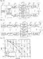
- Transceiving apparatussupporting a phase-shift based pre-coding method
- FIG. 9is a block diagram of an exemplary structure for a transceiving apparatus that supports the phase-shift based pre-coding method of the exemplary embodiments of the present invention.
- This exemplary embodiment of the transceiving apparatusassumes that the unitary matrix (U) for forming the phase-shift based pre-coding matrix is provided in codebook format, but is not meant to be limited to such, as described above.
- the transceiving apparatusmay be comprised of an input unit (901) used to select a desired function or receiving information, a display unit (903) used to show various information in using the transceiving apparatus, a memory unit (905) used to store various programs needed for operating the transceiving apparatus and data to be transmitted to the receiving side, a radio (wireless) communication unit (907) used to receive signals and transmit data to the receiving side, a voice processing unit (909) used to convert and amplify digital voice signals into analog voice signals for outputting through a speaker (SP) and to amplify the voice signals from a microphone (MIC) for converting into digital signals, and a control unit (911) used to control the overall operations of the transceiving apparatus.
- an input unit901 used to select a desired function or receiving information
- a display unitused to show various information in using the transceiving apparatus
- a memory unitused to store various programs needed for operating the transceiving apparatus and data to be transmitted to the receiving side
- FIG. 10is a block diagram showing an exemplary structure of a SCW (Single Codeword) OFDM transmitter unit that is included in the radio communication unit (907), and Figure 11 shows an exemplary structure of a MCW (Multiple Codeword) OFDM transmitter unit.
- SCWSingle Codeword
- MCWMultiple Codeword
- various receiver units that correspond to each transmitter unitalso exist and perform the opposite functions as those of the transmitter units, but their detailed explanations will be omitted merely for the sake of brevity.
- a channel encoder (101)adds redundancy bits to prevent the transmit data from being distorted at (over) the channel, and channel encoding is performed by using error correcting code codes (such as, turbo codes, LDPC codes, and the like).
- error correcting code codessuch as, turbo codes, LDPC codes, and the like.
- an interleaver (1020)performs interleaving through code bit parsing for minimizing losses due to instantaneous noise during the data transmission procedure, and a mapper (1030) converts the interleaved data bits into OFDM symbols.
- Such symbol mappingmay be performed through phase modulation techniques (such as, QPSK, etc.) and amplitude modulation techniques (such as, 16QAM, 8QAM, 4QAM, etc.).
- the OFDM symbolsare processed through the pre-coder (1040) of the present invention disclosure, then processed through a sub-channel modulator (not shown) and an Inverse Fast Fourier Transform (IFFT) unit (1050) are included into a carrier of the time domain.
- IFFTInverse Fast Fourier Transform
- filter unitnot shown
- analog converter1060
- transmission via a radio channelis performed.
- the OFDM symbolsare processed through a channel encoder (111) and an interleaver (1120) in a parallel manner for each channel, otherwise, the remaining structural element (1130-1160) may be the same (or similar).
- the pre-coding matrix forming module (1041, 1141)determines a reference column corresponding to a first sub-carrier in a particular pre-coding matrix, and the remaining columns are determined by phase-shifting the reference column using a phase angle that is increased by a certain (consistent) amount.
- a unitary matrix having a size of (number of transmit antennas) x (spatial multiplexing rate)is employed to perform pre-coding, and such unitary matrix is provided for each index of each sub-carrier, whereby the unitary matrix with respect to the first index is phase-shifted to obtain the unitary matrix of each remaining index.
- the pre-coding matrix forming module (1041, 1141)selects a certain 1 st precoding matrix from a codebook previously stored in the memory unit (905).
- a 2 nd precoding matrix with respect to a sub-carrier or a sub-band of the 2 nd indexis formed by applying a phase-shift of a certain size to the 1 st pre-coding matrix.
- the size of the shifted phasemay be variously set according to the current channel condition and/or whether or not feedback information from the receiving side exists.
- a 3 rd pre-coding matrix with respect to a sub-carrier or a sub-band of the 3 rd indexis formed by performing a phase-shift on the 2 nd pre-coding matrix. Namely, the forming procedure of the 2 nd pre-coding matrix is repeated during the formation procedure of the 3 rd precoding matrix through the last pre-coding matrix.
- the pre-coding matrix re-forming module (1042, 1142)selects a particular number of columns (in each pre-coding matrix formed by the pre-coding matrix forming module (1041, 1141)) that corresponds to the given spatial multiplexing rate and deletes the remaining columns in order to re-form a pre-coding matrix.
- a precoding matrix comprised of the above-described selected columnsmay be newly formed.
- one or more random columnsmay be selected or one or more particular columns may be selected according to pre-defined rules.
- the pre-coding module (1043, 1143)performs pre-coding by applying OFDM symbols for the corresponding sub-carrier into each pre-coding matrix determined in the above manner.
- the pre-coding matrix determining module (1041, 1141), the pre-coding matrix re-forming module (1042, 1142), and the pre-coding module (1043, 1143)will be explained.
- the pre-coding matrix determining module (1041, 1141)selects a particular unitary matrix (U) by referring to the unitary matrix index that was fed back from the receiving side or by using a pre-defined matrix, and the selected unitary matrix (U) is applied to the above Equation 13 to determine a phase-shift based pre-coding matrix (P).
- the phase-shift value of the former matrix of Equation 13should be previously set.
- the pre-coding re-forming module (1042, 1142)searches for a unitary matrix (U) that is appropriate for the corresponding situation or a previously selected unitary matrix (U) is re-formed to be appropriate for the corresponding situation.
- the pre-coding module (1043, 1143)performs pre-coding by applying the OFDM symbols (with respect to the corresponding sub-carrier or sub-band) to the phase-shift based pre-coding matrix determined in the above manner.
- the control unit (911)informs the pre-coding matrix re-forming module (1042, 1142) about various information (such as, the changed spatial multiplexing rate, the changed total number of antennas to be used, etc.) that is used for re-forming the precoding matrix.
- the transceiving apparatusmay be used in so-called Personal Digital Assistants (PDAs), cellular phones, Personal Communication Service (PCS) phones, GSM phones, WCDMA phones, Mobile Broadband System (MBS) phones, and the like.
- PDAsPersonal Digital Assistants
- PCSPersonal Communication Service
- GSMGlobal System for Mobile Communications
- WCDMAWireless Fidelity
- MBSMobile Broadband System
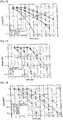
- Figure 12is a graph showing a comparison in performance differences when the phase-shift-based pre-coding (PSP) method of the present invention disclosure and the spatial multiplexing (SM) method of the background art are respectively applied to a ML (Minimum Likelihood) receiver and a MMSE (Minimum Mean Squared Error) receiver.
- PSPphase-shift-based pre-coding
- SMspatial multiplexing
- a larger gaincan generally be obtained when compared to the background art spatial multiplexing method. More specifically, in the ML receiver, the PSP method results in slightly more gain when compared to the SM method, but in the MMSE receiver, it can be seen that a larger gain may be obtained with the PSP method as the signal-to-noise ration (SNR) increases.
- SNRsignal-to-noise ration
- Figures 13 and 14are graphs showing a comparison of the performance differences per coding rate for the phase-shift based pre-coding method of the present invention disclosure and for the background art spatial multiplexing method being applied to a MMSE (Minimum Mean Squared Error) receiver for a Ped-A (ITU Pedestrian A) fading channel environment and a TU (Typical Urban) fading channel environment.
- MMSEMinimum Mean Squared Error
- Figures 15 through 17are graphs showing a comparison of the performance differences when the present invention disclosure phase-shift based pre-coding method and the background art spatial multiplexing method are applied to a system employing SCW (Single Codeword) and MCW (Multiple Codeword) in a Ped-A (ITU Pedestrian A) fading channel environment and a TU (Typical Urban) fading channel environment.
- SCWSingle Codeword
- MCWMultiple Codeword
- Figure 18is a graph showing the performance differences in the cases where the spatial diversity method + cyclic delay diversity method is applied, and the present invention disclosure phase-shift based pre-coding method + cyclic delay diversity method is applied to a MCS (Modulation and Coding Set) in a flat fading channel environment.
- MCSModulation and Coding Set
- phase-shift based pre-coding methodwhen compared to the space-time coding method, the degree of complexity of the transceiver is relatively low, the advantages of the phase-shift diversity scheme is maintained while supporting various spatial multiplexing rates. Compared to the pre-coding method, relatively less channel sensitivity and the need for a relatively small capacity codebook can be expected. Furthermore, by using a generalized phase-shift based pre-coding matrix, phase-shift based pre-coding can be easily expanded and applied regardless of the number of transmit antennas in the system.
- Figure 19shows an exemplary overview structure related to downlink baseband signal generation according to the present disclosure.
- radio communication techniquesmay include broadband wireless air interface techniques, Multiple-Input Multiple-Output (MIMO) techniques, so-called 3.5G or 4G systems designed to provide higher data rates and IP-based data services, etc. and/or various radio communication standards, such as, but not limited to, WCDMA, 3GPP, 3GPP2, OFDM, OFDMA, HSDPA, UMTS, OMA, IEEE 802.11n, IEEE 802.16, etc.
- MIMOMultiple-Input Multiple-Output
- 3.5G or 4G systemsdesigned to provide higher data rates and IP-based data services, etc.
- radio communication standardssuch as, but not limited to, WCDMA, 3GPP, 3GPP2, OFDM, OFDMA, HSDPA, UMTS, OMA, IEEE 802.11n, IEEE 802.16, etc.
- At least some of the features described hereinare applicable to such standards that have been developed or that are continuing to evolve. Also, at least some of the features described herein may be implemented in various types of devices (e.g., mobile phones, wireless communication terminals, user equipment (UE), radio communication protocol entities, etc.) in terms of hardware, software, or some appropriate combination thereof.
- devicese.g., mobile phones, wireless communication terminals, user equipment (UE), radio communication protocol entities, etc.
Landscapes
- Engineering & Computer Science (AREA)
- Computer Networks & Wireless Communication (AREA)
- Signal Processing (AREA)
- Physics & Mathematics (AREA)
- Discrete Mathematics (AREA)
- General Physics & Mathematics (AREA)
- Mathematical Physics (AREA)
- Radio Transmission System (AREA)
Description
- This disclosure relates to signal generation using phase-shift based pre-coding.
- Certain multi-carrier based wireless access techniques do not adequately support mobile communication systems with various types of antenna structures.
- The present inventors recognized certain shortcomings related to certain multi-carrier based multiple antenna transmitting and/or receiving techniques. Based upon such recognition, the following features have been conceived.
The document "Channel Dependent Scheduling with Cyclic Delay Diversity" NTT DOCOMO, 3GPP DRAFT, 2 May 2006, is related to a method for channel dependent scheduling with cyclic delay diversity (CDD), especially for a multi-degree CDD method with Frequency domain channel dependent scheduling.
Thedocument EP 0 771 084 is related to a time diversity transmission-reception system comprising a transmit side having at least one delay means of a predetermined delay for providing at least a pair of delayed and undelayed data symbol sequences.
The documentTEXAS INSTRUMENTS "Evaluation of Codebook-based Precoding for LTE MIMO Systems", 3GPP DRAFT, vol. RAN WG1, no. Shanghai, China, 2 May 2006, discloses four transmit closed loop MIMO as an option for LTE.
The document NORTEL "Closed Loop-MIMO Pre-coding and Feedback Design", 3GPP DRAFT, vol. TSG RAN, no. Denver, Colorado USA, 9 February 2006, discloses a link adaptation strategy using codebook-based precoding schemes. - A phase-shift based pre-coding method according to
claim 1 used in a transmitting side and a receiving side that has less complexity than those of a space-time coding scheme, that can support various spatial multiplexing rates while maintaining the advantages of the phase-shift diversity scheme, that has less channel sensitivity than that of the pre-coding scheme, and that only requires a low capacity codebook has been conceived and provided herein. In particular, the matrix used for performing phase-shift based pre-coding can be more easily expanded and implemented according to any changes in the number of antennas being employed. Embodiments of the invention are proposed in claims 2-8. Figure 1 shows an exemplary structure of a Multiple-Input Multiple-Output (MIMO) system using Orthogonal Frequency Division Multiplexing (OFDM).Figure 2 shows an exemplary structure of a transmitting side for a multiple antenna system using the cyclic delay diversity method.Figure 3 shows an exemplary structure of a transmitting side for a multiple antenna system using the phase-shift diversity method.Figure 4 is a graph showing examples of two types of phase-shift diversity methods.Figure 5 shows an exemplary structure of a transmitting side for a multiple antenna system using a pre-coding method.Figure 6 shows the exemplary procedures in performing a phase-shift diversity method in a system having 4 antennas with a spatial multiplexing rate of 2.Figure 7 shows an example of how a phase-shift based pre-coding method is applied to the system ofFigure 6 .Figure 8 shows an exemplary pre-coding matrix used in the phase-shift based pre-coding method for the system ofFigure 7 .Figure 9 shows an exemplary block diagram of a transceiving apparatus the supports the phase-shift based pre-coding method.Figure 10 shows an exemplary block diagram of a SCW OFDM transmitting unit within the radio communication unit ofFigure 9 .Figure 11 shows an exemplary block diagram of a MCW OFDM transmitting unit within the radio communication unit ofFigure 9 .Figure 12 is a graph showing a comparison in performance differences when the phase-shift pre-coding (PSP) method of the present invention disclosure and the spatial multiplexing (SM) method of the background art are respectively applied to a ML (Minimum Likelihood) receiver and a MMSE (Minimum Mean Squared Error) receiver.Figures 13 and 14 are graphs showing a comparison of the performance differences per coding rate for the phase-shift based pre-coding method of the present disclosure and for the background art spatial multiplexing method being applied to a MMSE (Minimum Mean Squared Error) receiver for a PedA (ITU Pedestrian A) fading channel environment and a TU (Typical Urban) fading channel environment.Figures 15 through 17 are graphs showing a comparison of the performance differences when the present disclosure phase-shift based pre-coding method and the background art spatial multiplexing method are applied to a system employing SCW (Single CodeWord) and MCW (Multi CodeWord) in a PedA (ITU Pedestrian A) fading channel environment and a TU (Typical Urban) fading channel environment.Figure 18 is a graph showing the performance differences in the cases where the spatial diversity method + cyclic delay diversity method is applied, and the present disclosure phase-shift based pre-coding method + cyclic delay diversity method is applied to a MCS (Modulation and Coding Set) in a flat fading channel environment.Figure 19 shows an exemplary overview structure of downlink baseband signal generation according to the present disclosure.- Information communication services have become more popular and with the introduction of various multimedia services and high quality services, there is an increased demand for enhanced wireless (radio) communication services. In order to actively meet such demands, the capacity and data transmission reliability of the communication system should be increased. To increase communication capacity in a wireless (radio) communication environment, one method would be to find newly usable bandwidth and another would be to improve the efficiency of given resources. As some examples of the latter method, multiple antenna transmitting/receiving (transceiving) techniques are recently gaining attention and being actively developed, whereby a plurality of antennas are provided at the transceiver in order to obtain diversity gain by additionally securing spatial domain for resource utilization, or increasing transmission capacity by transmitting data in parallel via each antenna.
- Among such multiple antenna transceving techniques, an example would be Multiple-Input Multiple-Output (MIMO) system based on Orthogonal Frequency Division Multiplexing (OFDM), the general structure of which will now be explained with reference to
Figure 1 . - At the transmitting side (or transmitter), a
channel encoder 101 serves the purpose of reducing the effects due to the channel or noise by attaching repetitive bits to the transmission data bits. Amapper 103 changes the data bit information into data symbol information. A serial-to-parallel converter 105 changes serial inputs into parallel outputs for the purpose of MIMO processing on the data symbols. In the receiving side (or receiver), amultiple antenna decoder 109, a parallel-to-serial converter 111, ademapper 113, and achannel decoder 115 perform the opposite operations as those of themultiple antenna encoder 107, the serial-to-parallel converter 105, themapper 103, and thechannel encoder 10 of the transmitting side described above. - In a multiple antenna OFDM system, various techniques are necessary to increase transmission reliability. For example, space-time code (STC) techniques, cyclic delay diversity (CDD) techniques, antenna selection (AS) techniques, antenna hopping (AH) techniques, spatial multiplexing (SM) techniques, beam-forming (BF) techniques, precoding techniques, and the like may be employed. Among these techniques, some will be explained in more detail hereafter.
- The space-time code (STC) technique, for a multiple antenna environment, relates to continuously (sequentially) transmitting the same signal, but in case of repetitive transmissions, transmitting through different antennas is performed, in order to obtain spatial diversity gain. The following matrix represents the most basic space-time code that is used in a system with two transmit antennas.

- In the above matrix, the rows represent antennas and the columns represent time slots.
- Such space-time code technique has some shortcoming. For example, respectively different forms of space-time codes are required according to how the antenna structure changes, the transmitting side and receiving side have increased complexity because data symbols are repeatedly transmitted through a plurality of time slots in order to obtain spatial diversity, and has respectively lower performance compared to that of other closed-loop systems because data is transmitted without using feedback information. Table 1 below shows the need for respectively different space-time codes according to antenna structures.
[Table 1] STC Scheme Spatial Multiplexing Rate # of Tx antennas 
1 2 
2 2 
2 2 

1 4 
1 4 
2 4 - Cyclic Delay Diversity (CDD) is a method in which frequency diversity gain is obtained at the receiving side, by using the antennas to respectively transmit signals with different delays or different magnitudes when transmitting OFDM signals in a system having multiple transceiving antennas.
Figure 2 shows a general structure of a transmitting side of a multiple antenna system using the cyclic delay diversity method.- Upon separating and delivering the OFDM symbols to each antenna via a serial-to-parallel converter and a multiple antenna encoder, an Inverse Fast Fourier Transform (IFFT) for changing a frequency domain signal into a time domain signal and a cyclic prefix (CP) for minimizing interference between channels are added and transmitted to the receiving side. Here, the data sequence delivered to the first antenna is transmitted to the receiving side as is (i.e., without any changes), while the data sequence transmitted from other transmit antennas is delayed in cyclic shift manner when compared to a first antenna.
- Meanwhile, when such cyclic delay diversity scheme is implemented in the frequency domain, the cyclic delay may be mathematically expressed as a multiplication of phase sequences.
- Namely, as can be seen in
Figure 3 , a particular phase sequence (e.g.,phase sequence 1 ∼ phase sequence M) that has been set differently for each antenna is multiplied to each data sequence in the frequency domain, and upon performing IFFT (Inverse Fast Fourier Transform) processing, such can be transmitted to the receiving side. This is referred to as a phase-shift diversity scheme. - By using the phase-shift diversity method, the flat fading channel may be changed to a frequency selectivity channel, and frequency diversity gain or frequency scheduling gain may be obtained according to a cyclic delay sample.
- Namely, as can be seen in
Figure 4 , in the phase-shift diversity scheme, when generating a phase sequence by using a relatively large value cyclic delay sample, because the phase variation period is shortened (decreased), frequency selectivity is increased and as a result, the channel codes may exploit frequency diversity gain. Such is typically used in so-called open-loop systems. - Also, when a small value cyclic delay is used, the phase variation period is lengthened (increased), and by using this in a closed-loop system, resources are allocated to the most satisfactory channel region such that frequency scheduling gain can be obtained. Namely, as can be seen in
Figure 4 , in the phase-shift diversity scheme, when a relatively small value cyclic delay is used for generating a phase sequence, certain sub-carrier regions of the flat fading channel result in an increase in channel magnitude, while other sub-carrier regions result in a decrease in channel magnitude. In such case, for an OFDMA system that accommodates multiple users, when a signal is transmitted through a sub-carrier having an increased channel magnitude per user, the signal-to-noise ratio can be increased. - However, despite some benefits of the above-described cyclic delay diversity scheme or phase-shift diversity scheme, because the spatial multiplexing rate is 1, the data transmission rate cannot be increased as desired.
- The pre-coding scheme may include a codebook based pre-coding method used when there is a finite (or limited) amount of feedback information in a closed-loop system and may include a method of performing feedback upon quantization of channel information. Here, codebook based pre-coding refers to obtaining signal-to-noise ratio (SNR) gain by feeding back, to the transmitting side, an index of a pre-coding matrix that is already known by both the transmitting side and the receiving side.
Figure 5 depicts an exemplary structure of a transceiving side of a multiple antenna system using codebook based pre-coding. Here, the transmitting side and the receiving side respectively have a finite pre-coding matrix(P1∼PL), and at the receiving side, channel information is used to feed back an optimal pre-coding matrix index (I), while at the transmitting side, a pre-coding matrix corresponding to the fed back index is applied to transmission data (x1∼xMt).- Such codebook based pre-coding scheme is beneficial in that effective data transmission is possible due to feedback of the index. However, because a stable channel is necessary, such codebook based pre-coding may not be fully appropriate for a mobile environment with severe channel changes. Also, some loss in the uplink transmission rate may occur due to the feedback overhead for the precoding matrix index. Additionally, because a codebook is needed in both the transmitting side and the receiving side, increased memory usage may be required.
- The present inventors recognized at least the above-described issues in certain data transmission, reception, and processing techniques for multiple antenna systems. Based upon such recognition, the following features have been conceived to address and/or to solve such issues.
- The present disclosure relates to a phase-shift based pre-coding method of a multiple antenna system using a plurality of sub-carriers, as well as a generalized phase-shift based pre-coding method and a transceiver device supporting the same.
- Hereafter, a phase-shift based pre-coding method will be explained with respect to a 2-antenna system and a 4-antenna system, and a method of forming a generalized phase-shift based pre-coding matrix to be extendedly used for a system with an Nt number of (physical or virtual) antennas will be described.
- A phase-shift based pre-coding matrix (P) proposed herein may be generally expressed in the following manner:

- Here,

- The pre-coding matrix (P) of
Equation 1 may be a unitary matrix for reducing the loss in channel capacity of a multiple antenna system. Here, to consider the conditions for forming a unitary matrix, the channel capacity of a multiple antenna system may be expressed by the following mathematical equation:
- Here, H refers to a multiple antenna channel matrix having a size of Nr x Nt, and Nr indicates the total number of receiving antennas. If a phase-shift based pre-coding matrix (P) is applied to the
above Equation 2, the following may be obtained:
- As shown in
Equation 3, to minimize channel loss,PPH needs to be an identity matrix, thus the phase-shift based pre-coding matrix (P) should be a unitary matrix such as the following:
- In order for the phase-shift based pre-coding matrix (P) to be a unitary matrix, two conditions should be satisfied. Namely, a power constraint and an orthogonality constraint should be simultaneously satisfied. Here, the power constraint refers to making the size of each column of the matrix to equal one (1), and the orthogonality constraint refers to making orthogonal characteristics between each column of the matrix to be satisfied. The above matters may be expressed mathematically in the following manner:


- As an exemplary embodiment, a generalized equation for a 2 x 2 phase-shift based pre-coding matrix will be provided, and a mathematical expression for satisfying the above-described two conditions will be examined. Equation 7 shows a generalized expression of a phase-shift based pre-coding matrix having a spatial diversity rate of 2 and having two transmit antennas.

- Here,αi, □i (i = 1, 2) are real numbers,θj (j = 1, 2, 3, 4) refers to phase values, and k is a sub-carrier index of the OFDM signal.
- In Equation 7, a relationship between a phase values θi (i=1, ..., 4) of a frequency domain and a cyclic delay value τi (i=1, ..., 4) of a time domain is expressed as follows:

where, Nfft denotes the number of subcarriers of the OFDM signal. - In order to implement such pre-coding matrix as a unitary matrix, the power constraint of
Equation 8 and the orthogonality constraint of Equation 9 should be satisfied.

- Here, the superscript (*) denotes a conjugate complex number. An example of a 2 x 2 phase-shift based pre-coding matrix that satisfies the above Equations 7 through 9 may be expressed as follows:

- Here,θ2 andθ3 have the relationship as shown in Equation 11 due to the orthogonality limitations.

- The pre-coding matrix may be stored in the form of a so-called codebook (or some equivalent type of precoding scheme, etc.) within a memory (or other type of storage device) of the transmitting side and the receiving side. Such codebook may include various types of pre-coding matrices formed by using a finite number of respectively differentθ2 values. Also, theθ2 value may be appropriately set according to the channel environment, transmission rank, system bandwidth and whether or not feedback information exists, and by setting theθ2 value to be relatively small (e.g., 2 cyclic delay samples) if feedback information is used or by setting theθ2 value is set to be relatively high (e.g., Nfft/Nt cyclic delay samples) if feedback information is not used, high frequency diversity gain may be obtained.
- Even when a phase-shift based pre-coding matrix such as that of Equation 7 is formed, situations where the spatial multiplexing rate should be set to be small compared to the actual number of antennas according to the channel environment may occur. In such case, in the phase-shift based pre-coding matrix formed in the above manner, a particular number of columns corresponding to the current spatial multiplexing rate (i.e., the spatial multiplexing rate that was made smaller) may be selected to re-generate a new phase-shift based pre-coding matrix. Namely, a new pre-coding matrix applied to the corresponding system need not always be formed whenever the spatial multiplexing rate changes. Instead, the initially formed phase-shift based precoding matrix may be employed as is (i.e., without any changes), but one or more particular columns of the corresponding matrix may be selected to re-form the precoding matrix.
- As one such example, the pre-coding matrix of the
above Equation 10 assumes that the multiple antenna system has 2 transmit antennas with a spatial multiplexing rate of 2, but there may be some situations where the spatial multiplexing rate may actually be reduced to 1 for some particular reason. In such case, pre-coding may be performed by selecting a particular column from the matrix ofEquation 10 above, and if the second column is selected, the phase-shift based pre-coding matrix is the same as that shown inEquation 12 below, and this becomes the same as the cyclic delay diversity scheme for two transmit antennas of the conventional art.
- Here, this example assumes a system having 2 transmit antennas, but such can also be expanded for applicability to systems with 4 (or more) antennas. Namely, after generating a phase-shift based pre-coding matrix for the case of 4 transmit antennas, pre-coding may be performed upon selecting one or more particular columns according to the changes in the spatial
multiplexing rate. - As an example,
Figure 6 shows a case where the related art spatial multiplexing and cyclic delay diversity are applied to a multiple antenna system having 4 transmit antennas and with a spatial multiplexing rate of 2, whileFigure 7 shows a case where the phase-shift based pre-coding matrix ofEquation 10 is applied to such a multiple antenna system. - According to
Figure 6 , a 1st sequence (S1) and a 2nd sequence (S2) are delivered to the 1st antenna and the 3rd antenna, and a 1st sequence (s1ejΘ1) and 2nd sequence (s2ejkΘ1) that have been phase-shifted by using phase sequence of ejkΘ1 are delivered to the 2nd antenna and the 4th antenna. Accordingly, it can be understood that the overall spatial multiplexing rate is 2. - On the other hand, according to
Figure 7 , s1 + s2ejkΘ2 is delivered to the 1st antenna, s1 ejkΘ1 + s2ejk(Θ1+Θ2) is delivered to the 2nd antenna, s1ejkΘ3 + s2 is delivered to the 3rd antenna, and s1ejk(Θ1+Θ3) + s2ejkΘ1 is delivered to the 4th antenna. Thus, when compared to the system ofFigure 6 , the advantage of the pre-coding method can be obtained, and because cyclic delay (or phase-shift) can be performed for 4 antennas by employing a uniform pre-coding matrix, the advantage of the cyclic delay diversity scheme can also be obtained. - As one of exmaple, the above-described phase-shift based pre-coding matrices per different spatial multiplexing rates with respect to a 2-antenna system and a 4-antenna system may be summarized as follows.
[Table 2] 2-antenna system 4-antenna system Spatial multiplexing rate 1Spatial multiplexing rate 2Spatial multiplexing rate 1Spatial multiplexing rate 2


- Here,θj(j= 1, 2, 3) refers to a phase angle according to the cyclic delay value, and k refers to an OFDM sub-carrier index. In Table 2 above, each pre-coding matrix of the four situations may be obtained by using a particular portion of the pre-coding matrix with respect to a multiple antenna system having 4 antennas with a spatial multiplexing rate of 2 (as can be seen in
Figure 8 ). Accordingly, each pre-coding matrix for such four situations need not be separately provided in a codebook, thus the memory resources in the transmitting side and the receiving side may be conserved. - Referring to Table 2, it should be noted that when forming an appropriate phase-shift based pre-coding matrix according to a changed spatial multiplexing rate, a new column that satisfies the orthogonal constraint to the other columns may be added.
- Thus far, the procedures of forming a phase-shift based pre-coding matrix when there are 4 transmit antennas with a spatial multiplexing rate of 2 was explained, but the phase-shift based pre-coding method of the present disclosure may be expanded to a system having N antennas (here, N being a natural number of 2 or greater) with a spatial multiplexing rate of R (here, R being a natural number of 1 or greater). Such may be obtained by using the same method described previously, and can be generalized as the following Equation 13.

- Here, at the right-side of the equal (=) symbol, the phase-shift diagonal matrix is combined with unitary matrix (U) used for a particular purpose that satisfies the following condition:

- By multiplying the phase-shift diagonal matrix and some unitary matrix, the phase-shift based precoding that satisfies both the power constraint and the orthogonal constraint may be obtained.
- In addition, the phase-shift based precoding matrix can be generated by multiplying one or more phase-shift diagonal matrices and/or one or more unitary matrices that can be obtained from feedback information or downlink channel state information. In equation 13, the phase-shift diagonal matrix can be implemented by time domain cyclic delay method if the k indicates sub-carrier index.
- As an example of the unitary matrix (U), a specific pre-coding matrix for obtaining signal-to-noise ratio (SNR) gain may be used, and in particular, if Walsh codes are used for such pre-coding matrix, the phase-shift based pre-coding matrix generating equation may be as follows:

- In
Equation 14, it is assumed that the system has 4 (physical or virtual) transmit antennas with a spatial multiplexing rate of 4. Here, by appropriately re-forming the unitary matrix (U), a particular transmit antenna may be selected (i.e., antenna selection) and/or the adjusting of spatial multiplexing rate (i.e., rate tuning) may be possible. - The following Equation 15 shows an example of how the unitary matrix (U) may be re-formed in order to
group 2 antennas of a system having 4 antennas.
- Also, the following Table 3 shows an exemplary method for re-forming the unitary matrix (U) to be appropriate for the corresponding multiplexing rate if the spatial multiplexing rate changes according to time, channel environment, and the like.

- Here, Table 3 shows some examples where
column 1, columns 1-2, andcolumns 1∼4 of the unitary is/are selected according to the multiplexing rate, but not meant to be limited to such. For example, if the multiplexing rate is 1, one of the 1st through 4th columns may be selected, if the multiplexing rate is 2, two particular columns (e.g., one pair among the (1,2), (2,3), (3,4), (1,3),..., (2,4) pairs of columns) may be selected, and if the multiplexing rate is 4, all columns may be selected. - Alternatively, the unitary matrix (U) may also be provided in codebook format in the transmitting side and the receiving side. In such case, the transmitting side receives index information of the codebook as feedback from the receiving side, then the appropriate unitary matrix (i.e., unitary precoding matrix in a codebook) corresponding to the index is selected from its codebook, and then the above Equation 13 is used to form a phase-shift based pre-coding matrix.
Figure 9 is a block diagram of an exemplary structure for a transceiving apparatus that supports the phase-shift based pre-coding method of the exemplary embodiments of the present invention. This exemplary embodiment of the transceiving apparatus assumes that the unitary matrix (U) for forming the phase-shift based pre-coding matrix is provided in codebook format, but is not meant to be limited to such, as described above.- The transceiving apparatus may be comprised of an input unit (901) used to select a desired function or receiving information, a display unit (903) used to show various information in using the transceiving apparatus, a memory unit (905) used to store various programs needed for operating the transceiving apparatus and data to be transmitted to the receiving side, a radio (wireless) communication unit (907) used to receive signals and transmit data to the receiving side, a voice processing unit (909) used to convert and amplify digital voice signals into analog voice signals for outputting through a speaker (SP) and to amplify the voice signals from a microphone (MIC) for converting into digital signals, and a control unit (911) used to control the overall operations of the transceiving apparatus.
- The radio communication unit (907) will be explained in more detail as follows. For reference,
Figure 10 is a block diagram showing an exemplary structure of a SCW (Single Codeword) OFDM transmitter unit that is included in the radio communication unit (907), andFigure 11 shows an exemplary structure of a MCW (Multiple Codeword) OFDM transmitter unit. Also, various receiver units that correspond to each transmitter unit also exist and perform the opposite functions as those of the transmitter units, but their detailed explanations will be omitted merely for the sake of brevity. - In the SCW OFDM transmitter unit, a channel encoder (101) adds redundancy bits to prevent the transmit data from being distorted at (over) the channel, and channel encoding is performed by using error correcting code codes (such as, turbo codes, LDPC codes, and the like). Thereafter, an interleaver (1020) performs interleaving through code bit parsing for minimizing losses due to instantaneous noise during the data transmission procedure, and a mapper (1030) converts the interleaved data bits into OFDM symbols. Such symbol mapping may be performed through phase modulation techniques (such as, QPSK, etc.) and amplitude modulation techniques (such as, 16QAM, 8QAM, 4QAM, etc.). Thereafter, the OFDM symbols are processed through the pre-coder (1040) of the present invention disclosure, then processed through a sub-channel modulator (not shown) and an Inverse Fast Fourier Transform (IFFT) unit (1050) are included into a carrier of the time domain. Upon processing through as filter unit (not shown) and an analog converter (1060), transmission via a radio channel is performed. Meanwhile, at the MCW OFDM transmitter unit, the only difference is that the OFDM symbols are processed through a channel encoder (111) and an interleaver (1120) in a parallel manner for each channel, otherwise, the remaining structural element (1130-1160) may be the same (or similar).
- The pre-coding matrix forming module (1041, 1141) determines a reference column corresponding to a first sub-carrier in a particular pre-coding matrix, and the remaining columns are determined by phase-shifting the reference column using a phase angle that is increased by a certain (consistent) amount. Here, a unitary matrix having a size of (number of transmit antennas) x (spatial multiplexing rate) is employed to perform pre-coding, and such unitary matrix is provided for each index of each sub-carrier, whereby the unitary matrix with respect to the first index is phase-shifted to obtain the unitary matrix of each remaining index.
- Namely, the pre-coding matrix forming module (1041, 1141) selects a certain 1st precoding matrix from a codebook previously stored in the memory unit (905). A 2nd precoding matrix with respect to a sub-carrier or a sub-band of the 2nd index is formed by applying a phase-shift of a certain size to the 1st pre-coding matrix. Here, the size of the shifted phase may be variously set according to the current channel condition and/or whether or not feedback information from the receiving side exists. A 3rd pre-coding matrix with respect to a sub-carrier or a sub-band of the 3rd index is formed by performing a phase-shift on the 2nd pre-coding matrix. Namely, the forming procedure of the 2nd pre-coding matrix is repeated during the formation procedure of the 3rd precoding matrix through the last pre-coding matrix.
- The pre-coding matrix re-forming module (1042, 1142) selects a particular number of columns (in each pre-coding matrix formed by the pre-coding matrix forming module (1041, 1141)) that corresponds to the given spatial multiplexing rate and deletes the remaining columns in order to re-form a pre-coding matrix. Here, a precoding matrix comprised of the above-described selected columns may be newly formed. In selecting the particular column(s) of the pre-coding matrix, one or more random columns may be selected or one or more particular columns may be selected according to pre-defined rules.
- The pre-coding module (1043, 1143) performs pre-coding by applying OFDM symbols for the corresponding sub-carrier into each pre-coding matrix determined in the above manner.
- Hereafter, the pre-coding matrix determining module (1041, 1141), the pre-coding matrix re-forming module (1042, 1142), and the pre-coding module (1043, 1143) according to another exemplary embodiment will be explained.
- The pre-coding matrix determining module (1041, 1141) selects a particular unitary matrix (U) by referring to the unitary matrix index that was fed back from the receiving side or by using a pre-defined matrix, and the selected unitary matrix (U) is applied to the above Equation 13 to determine a phase-shift based pre-coding matrix (P). Here, the phase-shift value of the former matrix of Equation 13 should be previously set.
- There may be situations where the spatial multiplexing rate needs to be adjusted due to changes in channel environment or where data transmission needs to be performed by selecting a particular antenna among multiple transmit antennas due to various reasons. In such case, when a change in spatial multiplexing rate and/or a change in the number of antennas is informed from the control unit (911), the pre-coding re-forming module (1042, 1142) searches for a unitary matrix (U) that is appropriate for the corresponding situation or a previously selected unitary matrix (U) is re-formed to be appropriate for the corresponding situation. In the former case, there is the advantage that the desired phase-shift based pre-coding matrix can be quickly obtained because a separate re-forming procedure is not necessary, but there is the disadvantage that memory usage increases because a codebook that is be used for various situations needs to be provided. Also, in the latter case, processing load is created due to the re-forming procedures, but the codebook capacity can be reduced. The unitary matrix re-forming procedure according to spatial multiplexing rate changes or changes in the number of transmit antennas was explained previously with respect to
Equation 14 and Table 3. - The pre-coding module (1043, 1143) performs pre-coding by applying the OFDM symbols (with respect to the corresponding sub-carrier or sub-band) to the phase-shift based pre-coding matrix determined in the above manner.
- The control unit (911) informs the pre-coding matrix re-forming module (1042, 1142) about various information (such as, the changed spatial multiplexing rate, the changed total number of antennas to be used, etc.) that is used for re-forming the precoding matrix.
- The transceiving apparatus according to the present invention disclosure may be used in so-called Personal Digital Assistants (PDAs), cellular phones, Personal Communication Service (PCS) phones, GSM phones, WCDMA phones, Mobile Broadband System (MBS) phones, and the like.
- By applying both the phase-shift based pre-coding method described herein and the spatial multiplexing method of the background art to a multiple antenna OFDM open loop system that does not employ feedback information, the differences in performance of these two methods will be explained with reference to some experimental test results. Table 4 shows the parameters that were applied to the system for this experimental test.
[Table] Parameter Parameter value # of sub-carriers 512 # of guard carriers 106 (left), 105 (right) # of pilots 28 (perfect channel estimation) MIMO scheme Spatial Multiplexing (SM) and phase-shift precoding (PSP) MIMO receiver MMSE (Minimum Mean Squared Error), ML (Minimum Likelihood) Bandwidth 7.68 MHz Carrier frequency 2 GHz Channel model Flat, Ped-A (ITU Pedestrian A), TU (Typical Urban), Mobility: 30 km/h, 250 km/h # of OFDM symbols per frame 8 (localized) MCS (Modulation and Coding Set) QPSK (R=1/4, R=1/3. R=1/2, R=3/4) Channel coding 3GPP Turbo (Max-long-MAP), 8 Iterations # of transmit antennas 2 # of receive antennas 2 Antenna correlation (0%,0%) Figure 12 is a graph showing a comparison in performance differences when the phase-shift-based pre-coding (PSP) method of the present invention disclosure and the spatial multiplexing (SM) method of the background art are respectively applied to a ML (Minimum Likelihood) receiver and a MMSE (Minimum Mean Squared Error) receiver.- As depicted, in a system that applies the PSP method, a larger gain can generally be obtained when compared to the background art spatial multiplexing method. More specifically, in the ML receiver, the PSP method results in slightly more gain when compared to the SM method, but in the MMSE receiver, it can be seen that a larger gain may be obtained with the PSP method as the signal-to-noise ration (SNR) increases.
Figures 13 and 14 are graphs showing a comparison of the performance differences per coding rate for the phase-shift based pre-coding method of the present invention disclosure and for the background art spatial multiplexing method being applied to a MMSE (Minimum Mean Squared Error) receiver for a Ped-A (ITU Pedestrian A) fading channel environment and a TU (Typical Urban) fading channel environment.- As depicted, it can be seen that on the Ped-A (ITU Pedestrian A) fading channel environment and the TU (Typical Urban) fading channel environment, the PSP method can obtain a large gain by increasing frequency selectivity while decreasing coding rate (R=1/3, R=1/4).
Figures 15 through 17 are graphs showing a comparison of the performance differences when the present invention disclosure phase-shift based pre-coding method and the background art spatial multiplexing method are applied to a system employing SCW (Single Codeword) and MCW (Multiple Codeword) in a Ped-A (ITU Pedestrian A) fading channel environment and a TU (Typical Urban) fading channel environment.- In general, when the spatial multiplexing method is applied to SCW, higher performance compared to that of MCW is achieved, because the channel code can additionally obtain spatial diversity gain and can obtain coding gain due to an increase in codeword length, but has the drawback that reception requires a high degree of complexity. As depicted, in a system with the spatial multiplexing method applied thereto, there is a large difference in performance between SCW and MCW. However, if the present invention disclosure phase-shift based pre-coding method is applied, a larger gain compared to that of the SCW of a system with the spatial multiplexing method applied thereto can be obtained. Namely, as depicted, a much larger gain is generated when phase-shift based pre-coding is applied in comparison to when the background art spatial multiplexing method is applied to MCW, and although a respectively smaller gain is generated compared to when SCW is applied, but it is clear that an improvement in performance is achieved.
Figure 18 is a graph showing the performance differences in the cases where the spatial diversity method + cyclic delay diversity method is applied, and the present invention disclosure phase-shift based pre-coding method + cyclic delay diversity method is applied to a MCS (Modulation and Coding Set) in a flat fading channel environment.- As depicted, for all coding rates (R=1/2, 1/3, 1/4), it can be seen that superior performance is achieved when the present invention disclosure phase-shift based precoding method + cyclic delay diversity method is applied, compared to when the background art spatial diversity method + cyclic delay diversity method is applied.
- As for some exemplary effects of the present invention disclosure that employs the phase-shift based pre-coding method, when compared to the space-time coding method, the degree of complexity of the transceiver is relatively low, the advantages of the phase-shift diversity scheme is maintained while supporting various spatial multiplexing rates. Compared to the pre-coding method, relatively less channel sensitivity and the need for a relatively small capacity codebook can be expected. Furthermore, by using a generalized phase-shift based pre-coding matrix, phase-shift based pre-coding can be easily expanded and applied regardless of the number of transmit antennas in the system.
Figure 19 shows an exemplary overview structure related to downlink baseband signal generation according to the present disclosure.- As for industrial applicability, the features and aspects described herein are related to and can be implemented for various types of radio communication techniques. Some non-limiting examples may include broadband wireless air interface techniques, Multiple-Input Multiple-Output (MIMO) techniques, so-called 3.5G or 4G systems designed to provide higher data rates and IP-based data services, etc. and/or various radio communication standards, such as, but not limited to, WCDMA, 3GPP, 3GPP2, OFDM, OFDMA, HSDPA, UMTS, OMA, IEEE 802.11n, IEEE 802.16, etc.
- As such, at least some of the features described herein are applicable to such standards that have been developed or that are continuing to evolve. Also, at least some of the features described herein may be implemented in various types of devices (e.g., mobile phones, wireless communication terminals, user equipment (UE), radio communication protocol entities, etc.) in terms of hardware, software, or some appropriate combination thereof.


Claims (8)
- A method of generating a signal to be transmitted by a multiple antenna system, the method comprising:modulating at least one source signal to obtain at least one modulated symbol; andphase-shift based pre-coding the at least one modulated symbol by multiplying the at least one modulated symbol by a complex-valued pre-coding matrix selected from a codebook,characterized in that:at least one element of the complex-valued pre-coding matrix is defined according to a resource index,wherein the resource index corresponds to a sub-carrier index in an Orthogonal Frequency Division Multiplexing based system,wherein the codebook comprises a first complex-valued pre-coding matrix for a first multiplexing rate and a second complex-valued pre-coding matrix for a second multiplexing rate,wherein the second multiplexing rate is greater than the first multiplexing rate, andwherein all column vectors of the first complex-valued pre-coding matrix are included as a part of column vectors of the second complex-valued pre-coding matrix.
- The method of claim 1, wherein the complex-valued pre-coding matrix is a unitary matrix.
- The method of claim 1, wherein the complex-valued pre-coding matrix is generated by combining it with at least one unitary matrix.
- The method of claim 3, wherein the at least one unitary matrix includes at least one diagonal phase shift matrix.
- The method of claim 4, wherein the diagonal phase shift matrix is expressed as:

- The method of claim 1, wherein, if a number of the modulated symbol is decreased, the number of columns of the complex-valued pre-coding matrix is decreased by selecting at least one column corresponding to the decreased number of the modulated symbol of the complex-valued pre-coding matrix.
- The method of claim 1, wherein the first complex-valued pre-coding matrix is generated by selecting one or more columns of the second complex-valued pre-coding matrix.
- The method of claim 1, wherein the pre-coding step employs rank adaptation or rate adaptation.

Applications Claiming Priority (4)
| Application Number | Priority Date | Filing Date | Title |
|---|---|---|---|
| US80334006P | 2006-05-26 | 2006-05-26 | |
| KR20060065303 | 2006-07-12 | ||
| KR1020060097216AKR100934657B1 (en) | 2006-05-26 | 2006-10-02 | Phase shift based precoding method and transceiver |
| PCT/KR2007/002563WO2007139325A1 (en) | 2006-05-26 | 2007-05-28 | Signal generation using phase-shift based pre-coding |
Publications (3)
| Publication Number | Publication Date |
|---|---|
| EP2030393A1 EP2030393A1 (en) | 2009-03-04 |
| EP2030393A4 EP2030393A4 (en) | 2012-09-05 |
| EP2030393B1true EP2030393B1 (en) | 2018-01-24 |
Family
ID=39091685
Family Applications (1)
| Application Number | Title | Priority Date | Filing Date |
|---|---|---|---|
| EP07746711.6ANot-in-forceEP2030393B1 (en) | 2006-05-26 | 2007-05-28 | Signal generation using phase-shift based pre-coding |
Country Status (10)
| Country | Link |
|---|---|
| US (3) | US8036286B2 (en) |
| EP (1) | EP2030393B1 (en) |
| JP (1) | JP5264711B2 (en) |
| KR (2) | KR100928260B1 (en) |
| CN (1) | CN101461205B (en) |
| BR (1) | BRPI0711735A2 (en) |
| MX (1) | MX2008015036A (en) |
| RU (1) | RU2439834C2 (en) |
| TW (1) | TWI343200B (en) |
| WO (1) | WO2007139325A1 (en) |
Families Citing this family (127)
| Publication number | Priority date | Publication date | Assignee | Title |
|---|---|---|---|---|
| EP1878133B1 (en)* | 2005-04-26 | 2015-03-04 | Intellectual Ventures I LLC | Systems and methods for transmitter diversity expansion |
| US7917176B2 (en)* | 2006-02-14 | 2011-03-29 | Nec Laboratories America, Inc. | Structured codebook and successive beamforming for multiple-antenna systems |
| US8879477B2 (en)* | 2006-03-29 | 2014-11-04 | Telefonaktiebolaget Lm Ericsson (Publ) | Radio coverage enhancement |
| KR20070113967A (en) | 2006-05-26 | 2007-11-29 | 엘지전자 주식회사 | Phase shift based precoding method and tranceiver supporting the same |
| MX2009000066A (en) | 2006-07-06 | 2009-02-17 | Lg Electronics Inc | Method and apparatus for correcting errors in a multiple subcarriers communication system using multiple antennas. |
| WO2008021392A2 (en)* | 2006-08-17 | 2008-02-21 | Interdigital Technology Corporation | Method and apparatus for reducing a peak-to-average power ratio in a multiple-input multiple-output system |
| US7839835B2 (en)* | 2006-08-22 | 2010-11-23 | Nec Laboratories America, Inc. | Quantized precoding over a set of parallel channels |
| KR20080022033A (en)* | 2006-09-05 | 2008-03-10 | 엘지전자 주식회사 | Precoding Information Feedback Method and Precoding Method |
| KR101099881B1 (en)* | 2006-09-06 | 2011-12-28 | 고려대학교 산학협력단 | Method and device for antenna selection in orthogonal spatial multiplexing system |
| KR20080026010A (en)* | 2006-09-19 | 2008-03-24 | 엘지전자 주식회사 | Data transmission method using phase shift based precoding and transmitting and receiving device |
| US8503560B2 (en)* | 2006-10-02 | 2013-08-06 | Samsung Electronics Co., Ltd | System and method for performing precoding in a wireless communication system |
| KR101163280B1 (en) | 2006-10-03 | 2012-07-10 | 인터디지탈 테크날러지 코포레이션 | Combined open loop/closed loop cqi-based uplink transmit power control with interference mitigation for e-utra |
| US7961640B2 (en)* | 2006-10-26 | 2011-06-14 | Qualcomm Incorporated | Method and apparatus for codebook exchange in a multiple access wireless communication system |
| US7634233B2 (en)* | 2006-11-27 | 2009-12-15 | Chung Shan Institute Of Science And Technology | Transmission system with interference avoidance capability and method thereof |
| US7812827B2 (en) | 2007-01-03 | 2010-10-12 | Apple Inc. | Simultaneous sensing arrangement |
| US8780771B2 (en)* | 2007-02-06 | 2014-07-15 | Qualcomm Incorporated | Cyclic delay diversity and precoding for wireless communication |
| US8509710B2 (en) | 2007-02-06 | 2013-08-13 | Qualcomm Incorporated | MIMO transmission with explicit and implicit cyclic delays |
| KR20080076683A (en) | 2007-02-14 | 2008-08-20 | 엘지전자 주식회사 | Phase Shift-Based Precoding Method and Transceivers Supporting It |
| US20080227414A1 (en)* | 2007-03-01 | 2008-09-18 | Yair Karmi | System, method and apparatus for transmit diversity control based on variations in propagation path |
| US8509836B2 (en) | 2007-03-07 | 2013-08-13 | Interdigital Technology Corporation | Combined open loop/closed loop method for controlling uplink power of a mobile station |
| US8254492B2 (en)* | 2007-04-26 | 2012-08-28 | Samsung Electronics Co., Ltd. | Transmit diversity in a wireless communication system |
| US20080273452A1 (en)* | 2007-05-04 | 2008-11-06 | Farooq Khan | Antenna mapping in a MIMO wireless communication system |
| US8155232B2 (en)* | 2007-05-08 | 2012-04-10 | Samsung Electronics Co., Ltd. | Multiple antennas transmit diversity scheme |
| US8325852B2 (en) | 2007-06-08 | 2012-12-04 | Samsung Electronics Co., Ltd. | CDD precoding for open loop SU MIMO |
| US8493331B2 (en) | 2007-06-13 | 2013-07-23 | Apple Inc. | Touch detection using multiple simultaneous frequencies |
| US8928459B2 (en)* | 2007-06-15 | 2015-01-06 | Worcester Polytechnic Institute | Precision location methods and systems |
| US8160177B2 (en)* | 2007-06-25 | 2012-04-17 | Samsung Electronics Co., Ltd. | Transmit methods with delay diversity and space-frequency diversity |
| US7907677B2 (en)* | 2007-08-10 | 2011-03-15 | Intel Corporation | Open loop MU-MIMO |
| KR20090030200A (en) | 2007-09-19 | 2009-03-24 | 엘지전자 주식회사 | Data Transceiving Method Using Phase-Transition-Based Precoding and Transceivers Supporting It |
| EP3322108B1 (en)* | 2007-10-08 | 2019-04-24 | Telefonaktiebolaget LM Ericsson (publ) | Methods and arrangements for signaling control information in a communication system |
| EP2661003B1 (en)* | 2008-01-04 | 2019-05-01 | Sun Patent Trust | Radio Communication Terminal Device and Radio Transmission Method |
| KR101328961B1 (en)* | 2008-03-14 | 2013-11-13 | 엘지전자 주식회사 | Method For Transmitting And Receiving Signals In Open-Loop Spatial Multiplexing Mode |
| KR101349831B1 (en)* | 2008-03-23 | 2014-01-09 | 엘지전자 주식회사 | Method For Transmitting Signals For Reducing Feedback Overhead and Method For Transmitting Feedback Information For The Same |
| US8233939B2 (en)* | 2008-03-31 | 2012-07-31 | Intel Corporation | Multiuser sector micro diversity system |
| KR101728834B1 (en) | 2008-04-29 | 2017-04-20 | 애플 인크. | Improved performance for a multiple antenna beamforming cellular network |
| JP5226122B2 (en)* | 2008-05-05 | 2013-07-03 | エルジー エレクトロニクス インコーポレイティド | Cyclic delay diversity based forwarding with delay hopping |
| KR101507835B1 (en)* | 2008-05-08 | 2015-04-06 | 엘지전자 주식회사 | Transmit diversity method in multi-antenna system |
| JP5031670B2 (en)* | 2008-06-02 | 2012-09-19 | 株式会社日立製作所 | Transmitting apparatus, base station, and symbol transmitting method |
| US9225575B2 (en) | 2008-06-18 | 2015-12-29 | Center Of Excellence In Wireless Technology | Precoding for single transmission streams in multiple antenna systems |
| US9083399B2 (en)* | 2008-06-18 | 2015-07-14 | Centre Of Excellence In Wireless Technology | Precoding for single transmission streams in multiple antenna systems |
| EP2305007B1 (en)* | 2008-07-08 | 2012-12-12 | Koninklijke Philips Electronics N.V. | Methods and apparatus for determining relative positions of led lighting units |
| US20100034310A1 (en)* | 2008-08-08 | 2010-02-11 | Samsung Electronics Co., Ltd. | Transmit diversity schemes in OFDM systems |
| WO2010018969A2 (en) | 2008-08-11 | 2010-02-18 | Lg Electronics Inc. | Method and apparatus for transmitting uplink signals using multi-antenna |
| KR20100019948A (en)* | 2008-08-11 | 2010-02-19 | 엘지전자 주식회사 | Method of transmitting data using spatial multiplexing |
| WO2010018957A2 (en)* | 2008-08-11 | 2010-02-18 | 엘지전자주식회사 | Method for transmitting multiple code words in a multiple antenna system |
| TWI435559B (en)* | 2008-08-14 | 2014-04-21 | 韓國電子通信研究院 | Method to generate beamforming vector and provide the information for generating beamforming vector |
| KR101268687B1 (en)* | 2008-08-18 | 2013-05-29 | 한국전자통신연구원 | Communication system including basestations and terminal for multi-cell cooperative communication |
| KR101481589B1 (en)* | 2008-08-25 | 2015-01-12 | 엘지전자 주식회사 | Method of feedback information transmition, method and apparatus of data transmition in a wireless communication system having multiple antennas |
| US8592697B2 (en) | 2008-09-10 | 2013-11-26 | Apple Inc. | Single-chip multi-stimulus sensor controller |
| US9348451B2 (en) | 2008-09-10 | 2016-05-24 | Apple Inc. | Channel scan architecture for multiple stimulus multi-touch sensor panels |
| US9606663B2 (en)* | 2008-09-10 | 2017-03-28 | Apple Inc. | Multiple stimulation phase determination |
| US8391392B2 (en) | 2009-01-05 | 2013-03-05 | Marvell World Trade Ltd. | Precoding codebooks for MIMO communication systems |
| CN101771648B (en)* | 2009-01-06 | 2018-03-23 | 中兴通讯股份有限公司 | A kind of multi-antenna signal processing system and method |
| US8385441B2 (en) | 2009-01-06 | 2013-02-26 | Marvell World Trade Ltd. | Efficient MIMO transmission schemes |
| KR101608779B1 (en)* | 2009-02-13 | 2016-04-20 | 엘지전자 주식회사 | Uplink Precoding Method In 2 Tx System |
| US8238483B2 (en) | 2009-02-27 | 2012-08-07 | Marvell World Trade Ltd. | Signaling of dedicated reference signal (DRS) precoding granularity |
| EP3512219B1 (en)* | 2009-04-06 | 2022-05-04 | Marvell Asia Pte, Ltd. | Improved feedback strategies for multi-user mimo communication systems |
| US8649344B2 (en) | 2009-04-15 | 2014-02-11 | Lg Electronics Inc. | Method of coordinating precoding matrixes in a wireless communication system |
| CN102405603B (en) | 2009-04-21 | 2015-04-29 | 马维尔国际贸易有限公司 | Method, device and system for beamforming with selective beam attenuation |
| CN102239648B (en)* | 2009-04-27 | 2015-12-02 | 华为技术有限公司 | Based on up launching technique and the equipment of code book |
| KR101647377B1 (en)* | 2009-05-22 | 2016-08-10 | 엘지전자 주식회사 | A method for adaptive multi-antenna transmission based on antenna transmission power in wireless communication system and apparatus thereof |
| WO2010142323A1 (en)* | 2009-06-08 | 2010-12-16 | Telefonaktiebolaget L M Ericsson (Publ) | Wireless communication node connections |
| US8675794B1 (en) | 2009-10-13 | 2014-03-18 | Marvell International Ltd. | Efficient estimation of feedback for modulation and coding scheme (MCS) selection |
| US8917796B1 (en) | 2009-10-19 | 2014-12-23 | Marvell International Ltd. | Transmission-mode-aware rate matching in MIMO signal generation |
| US8811518B2 (en) | 2009-11-02 | 2014-08-19 | Pantech Co., Ltd. | Method and transmitter for transmitting signal and receiver thereof in wireless communication system |
| WO2011055238A1 (en)* | 2009-11-09 | 2011-05-12 | Marvell World Trade Ltd | Asymmetrical feedback for coordinated transmission systems |
| EP2514181B1 (en) | 2009-12-17 | 2018-10-03 | Marvell World Trade Ltd. | Mimo feedback schemes for cross-polarized antennas |
| JP6012472B2 (en) | 2010-01-07 | 2016-10-25 | マーベル ワールド トレード リミテッド | Dedicated reference signal (DRS) precoding granularity notification, method, communication apparatus and mobile communication terminal |
| US8948289B2 (en)* | 2010-01-12 | 2015-02-03 | Lg Electronics Inc. | Method and device for codebook generation and downlink signal transmission in a wireless communication system supporting multiple antennas |
| WO2011090353A2 (en) | 2010-01-22 | 2011-07-28 | 엘지전자 주식회사 | Method and apparatus for providing downlink control information in an mimo wireless communication system |
| JP2011166536A (en)* | 2010-02-10 | 2011-08-25 | Sharp Corp | Radio transmitter, base station device, radio transmission method, and control program and integrated circuit of base station device |
| JP5258002B2 (en) | 2010-02-10 | 2013-08-07 | マーベル ワールド トレード リミテッド | Device, mobile communication terminal, chipset, and method in MIMO communication system |
| CN101800628B (en)* | 2010-02-12 | 2015-09-16 | 中兴通讯股份有限公司 | A kind of method and system obtaining channel condition information |
| US8687741B1 (en) | 2010-03-29 | 2014-04-01 | Marvell International Ltd. | Scoring hypotheses in LTE cell search |
| CN102237973B (en)* | 2010-05-04 | 2014-07-30 | 华为技术有限公司 | Precoding processing method and user equipment |
| CN104135348B (en)* | 2010-05-04 | 2018-03-27 | 华为技术有限公司 | Precoding processing method and user equipment |
| CN101854712A (en)* | 2010-06-18 | 2010-10-06 | 华为技术有限公司 | Power balance method and device between antennas, and base station |
| WO2012002767A2 (en)* | 2010-07-02 | 2012-01-05 | 엘지전자 주식회사 | Method and apparatus for transmitting signals using codebooks in a wireless communication system that supports multiple antennas |
| KR101081317B1 (en)* | 2010-07-12 | 2011-11-08 | 전북대학교산학협력단 | Distributed ΜΙΜΟ Channel Precoding and Decoding Method in Relay-based DFF Cooperative Wireless Network |
| KR101754669B1 (en) | 2010-07-29 | 2017-07-06 | 엘지전자 주식회사 | Method and device for sending and receiving precoded signals on a wireless communication system |
| KR20120030200A (en)* | 2010-09-17 | 2012-03-28 | 주식회사 팬택 | Apparatus and method of transmitting data using multiple antenna and beam forming |
| US8615052B2 (en) | 2010-10-06 | 2013-12-24 | Marvell World Trade Ltd. | Enhanced channel feedback for multi-user MIMO |
| JP2012100254A (en) | 2010-10-06 | 2012-05-24 | Marvell World Trade Ltd | Codebook subsampling for pucch feedback |
| JP5578619B2 (en) | 2010-12-10 | 2014-08-27 | パナソニック インテレクチュアル プロパティ コーポレーション オブ アメリカ | Transmitter and receiver |
| EP3965324A3 (en) | 2010-12-10 | 2022-03-23 | Sun Patent Trust | Signal generation method and signal generation device |
| US9048970B1 (en) | 2011-01-14 | 2015-06-02 | Marvell International Ltd. | Feedback for cooperative multipoint transmission systems |
| US8861391B1 (en) | 2011-03-02 | 2014-10-14 | Marvell International Ltd. | Channel feedback for TDM scheduling in heterogeneous networks having multiple cell classes |
| US20120224651A1 (en)* | 2011-03-03 | 2012-09-06 | Yutaka Murakami | Signal generation method and signal generation apparatus |
| CN103548284B (en) | 2011-03-31 | 2017-07-21 | 马维尔国际贸易有限公司 | Channel feedback for cooperative multipoint transmission |
| EP3358755B1 (en)* | 2011-04-19 | 2019-09-04 | Sun Patent Trust | Transmission and reception method and apparatus |
| CN102769484B (en)* | 2011-05-03 | 2016-02-24 | 上海贝尔股份有限公司 | Generate the code book being used for uniform circular array row and the method obtaining code word from this code book |
| KR101434222B1 (en) | 2011-09-27 | 2014-09-19 | 서울과학기술대학교 산학협력단 | Orthogonal complex pre-coding apparatus and mehtod in open loop multiple input multiple output system |
| WO2013048065A2 (en)* | 2011-09-27 | 2013-04-04 | Jang Jung-Yup | Orthogonal complex pre-coding apparatus and method in an open loop multi-antenna system |
| US9450659B2 (en)* | 2011-11-04 | 2016-09-20 | Alcatel Lucent | Method and apparatus to generate virtual sector wide static beams using phase shift transmit diversity |
| US8923427B2 (en) | 2011-11-07 | 2014-12-30 | Marvell World Trade Ltd. | Codebook sub-sampling for frequency-selective precoding feedback |
| WO2013068915A2 (en) | 2011-11-07 | 2013-05-16 | Marvell World Trade Ltd. | Precoding feedback for cross-polarized antennas with magnitude information |
| WO2013068974A1 (en) | 2011-11-10 | 2013-05-16 | Marvell World Trade Ltd. | Differential cqi encoding for cooperative multipoint feedback |
| US9220087B1 (en) | 2011-12-08 | 2015-12-22 | Marvell International Ltd. | Dynamic point selection with combined PUCCH/PUSCH feedback |
| US8902842B1 (en) | 2012-01-11 | 2014-12-02 | Marvell International Ltd | Control signaling and resource mapping for coordinated transmission |
| EP2842361B1 (en) | 2012-04-27 | 2019-03-27 | Marvell World Trade Ltd. | Coordinated multipoint (comp) communication between base-stations and mobile communication terminals |
| US9362989B2 (en)* | 2012-05-22 | 2016-06-07 | Sun Patent Trust | Transmission method, reception method, transmitter, and receiver |
| KR101959322B1 (en) | 2013-04-28 | 2019-03-18 | 후아웨이 테크놀러지 컴퍼니 리미티드 | Precoding matrix indicator feedback method, receiving end and transmitting end |
| GB2515892B (en) | 2013-05-13 | 2016-02-24 | British Broadcasting Corp | Transmission techniques |
| CN104283645B (en)* | 2013-07-05 | 2019-04-05 | 三星电子株式会社 | Sending device and sending method |
| KR102097295B1 (en) | 2013-07-26 | 2020-04-06 | 한국전자통신연구원 | Apparatus and method for encoding in multiple input multiple output communication systems |
| US9425929B2 (en)* | 2014-06-26 | 2016-08-23 | Alcatel Lucent | Wireless communication with suppression of inter-cell interference in large-scale antenna systems |
| CN105721030B (en)* | 2014-12-04 | 2019-05-10 | 中国移动通信集团公司 | A beamforming method and base station |
| CN106612135B (en)* | 2015-10-19 | 2021-07-27 | 北京三星通信技术研究有限公司 | Signal transmission method, reception method and device based on multi-carrier spatial modulation |
| CN106685495A (en)* | 2015-11-05 | 2017-05-17 | 索尼公司 | Wireless communication method and wireless communication device |
| KR101706629B1 (en)* | 2016-01-25 | 2017-02-16 | 주식회사 이노와이어리스 | power calibration method for MIMO-OFDM transmitter |
| CN105812041B (en)* | 2016-03-31 | 2018-10-09 | 河南理工大学 | A kind of method for eliminating multi-user interference in the MIMO broadcast channels of two cells |
| CA3020075C (en) | 2016-04-27 | 2024-02-27 | Panasonic Intellectual Property Corporation Of America | Transmission apparatus and transmission method |
| JP6167439B2 (en)* | 2016-06-29 | 2017-07-26 | サン パテント トラスト | Transmitter and receiver |
| EP3480967B1 (en)* | 2016-06-30 | 2021-05-19 | Panasonic Intellectual Property Corporation of America | Transmitting device and transmitting method |
| EP3264628A1 (en) | 2016-07-01 | 2018-01-03 | Alcatel Lucent | A method for transmitting radio signals from a base station, a system and a computer program product |
| EP3282662B1 (en)* | 2016-08-12 | 2021-05-12 | Institut Mines Telecom / Telecom Bretagne | Reduced complexity transmitter for universal filtered ofdm |
| US9847802B1 (en)* | 2016-08-16 | 2017-12-19 | Xilinx, Inc. | Reconfiguration of single-band transmit and receive paths to multi-band transmit and receive paths in an integrated circuit |
| CN106788884A (en)* | 2016-12-05 | 2017-05-31 | 渤海大学 | A kind of multi-channel data transmission method |
| KR102338306B1 (en)* | 2017-03-23 | 2021-12-10 | 엘지전자 주식회사 | Method for transmitting and receiving channel state information in a wireless communication system and apparatus therefor |
| WO2018198917A1 (en)* | 2017-04-24 | 2018-11-01 | パナソニック インテレクチュアル プロパティ コーポレーション オブ アメリカ | Transmission device and transmission method |
| JP6312013B2 (en)* | 2017-06-08 | 2018-04-18 | サン パテント トラスト | Transmitter and receiver |
| US10644771B2 (en)* | 2018-06-08 | 2020-05-05 | University Of South Florida | Using artificial signals to maximize capacity and secrecy of multiple-input multiple-output (MIMO) communication |
| US10516452B1 (en)* | 2018-06-08 | 2019-12-24 | University Of South Florida | Using artificial signals to maximize capacity and secrecy of multiple-input multiple-output (MIMO) communication |
| CN110971275B (en)* | 2018-09-28 | 2021-11-23 | 大唐移动通信设备有限公司 | Uplink transmission method, uplink transmission scheduling method and device |
| US11881915B2 (en)* | 2019-04-05 | 2024-01-23 | Lg Electronics Inc. | Method for transmitting and receiving signal in wireless communication system, and apparatus therefor |
| JP7117533B2 (en)* | 2019-07-04 | 2022-08-15 | サン パテント トラスト | transmitter and receiver |
| US12244446B2 (en)* | 2020-12-14 | 2025-03-04 | Telefonaktiebolaget Lm Ericsson (Publ) | Transform for communication symbols |
Family Cites Families (78)
| Publication number | Priority date | Publication date | Assignee | Title |
|---|---|---|---|---|
| JPH09116475A (en)* | 1995-10-23 | 1997-05-02 | Nec Corp | Time diversity transmission / reception system |
| US6891897B1 (en)* | 1999-07-23 | 2005-05-10 | Nortel Networks Limited | Space-time coding and channel estimation scheme, arrangement and method |
| SG80071A1 (en) | 1999-09-24 | 2001-04-17 | Univ Singapore | Downlink beamforming method |
| US6298092B1 (en)* | 1999-12-15 | 2001-10-02 | Iospan Wireless, Inc. | Methods of controlling communication parameters of wireless systems |
| US6792049B1 (en)* | 2000-06-15 | 2004-09-14 | Mitsubishi Electric Research Laboratories, Inc. | Digital transceiver system with adaptive channel pre-coding in an asymmetrical communications network |
| US6760882B1 (en)* | 2000-09-19 | 2004-07-06 | Intel Corporation | Mode selection for data transmission in wireless communication channels based on statistical parameters |
| US6802035B2 (en)* | 2000-09-19 | 2004-10-05 | Intel Corporation | System and method of dynamically optimizing a transmission mode of wirelessly transmitted information |
| US6785341B2 (en) | 2001-05-11 | 2004-08-31 | Qualcomm Incorporated | Method and apparatus for processing data in a multiple-input multiple-output (MIMO) communication system utilizing channel state information |
| JP2003018127A (en)* | 2001-07-03 | 2003-01-17 | Fujitsu Ltd | Transmitter and receiver |
| US20030048753A1 (en) | 2001-08-30 | 2003-03-13 | Ahmad Jalali | Method and apparatus for multi-path elimination in a wireless communication system |
| US7301893B2 (en)* | 2001-11-21 | 2007-11-27 | Texas Instruments Incorporated | Linear space-time block code with block STTD structure |
| KR100896682B1 (en) | 2002-04-09 | 2009-05-14 | 삼성전자주식회사 | Mobile communication device and method including transmit / receive multiple antenna |
| US7613248B2 (en) | 2002-06-24 | 2009-11-03 | Qualcomm Incorporated | Signal processing with channel eigenmode decomposition and channel inversion for MIMO systems |
| EP1408623B1 (en)* | 2002-10-10 | 2010-12-15 | Samsung Electronics Co., Ltd. | Transmitting and receiving apparatus for supporting transmit antenna diversity using space-time block code. |
| US7151809B2 (en) | 2002-10-25 | 2006-12-19 | Qualcomm, Incorporated | Channel estimation and spatial processing for TDD MIMO systems |
| RU2351071C2 (en) | 2002-10-25 | 2009-03-27 | Квэлкомм Инкорпорейтед | Channel evaluation and spatial processing for tdd mimo systems |
| TW589818B (en) | 2002-11-22 | 2004-06-01 | Chung Shan Inst Of Science | Method of transmit diversity using TDD wideband multi-carrier DS-CDMA system |
| FR2848747A1 (en)* | 2002-12-16 | 2004-06-18 | France Telecom | Pre-coded signal emitting process for wireless communication system, involves interlacing pre-coded transmitted symbols to modify temporal order of symbols and coding each block of symbols according to coding time space |
| KR100552680B1 (en) | 2003-02-17 | 2006-02-20 | 삼성전자주식회사 | Method for reducing PRA in multi-antenna OMD communication system and multi-antenna OMD communication system using same |
| US20040192218A1 (en) | 2003-03-31 | 2004-09-30 | Oprea Alexandru M. | System and method for channel data transmission in wireless communication systems |
| FR2863422A1 (en) | 2003-12-04 | 2005-06-10 | France Telecom | Signal transmitting method for wireless digital communication, involves implementing source matrix and linear precoding matrix to provide precoded matrix, and transmitting precoded vectors conforming to columns of precoded matrix |
| WO2005055465A1 (en) | 2003-12-05 | 2005-06-16 | Samsung Electronics Co., Ltd. | Apparatus and method for transmitting data by selected eigenvector in closed loop mimo mobile communication system |
| US7447268B2 (en)* | 2004-03-31 | 2008-11-04 | Intel Corporation | OFDM system with per subcarrier phase rotation |
| US7417974B2 (en) | 2004-04-14 | 2008-08-26 | Broadcom Corporation | Transmitting high rate data within a MIMO WLAN |
| US8285226B2 (en)* | 2004-05-07 | 2012-10-09 | Qualcomm Incorporated | Steering diversity for an OFDM-based multi-antenna communication system |
| US8233555B2 (en)* | 2004-05-17 | 2012-07-31 | Qualcomm Incorporated | Time varying delay diversity of OFDM |
| US8588203B2 (en) | 2004-06-04 | 2013-11-19 | Qualcomm Incorporated | Wireless communication system with improved broadcast coverage |
| KR100754795B1 (en) | 2004-06-18 | 2007-09-03 | 삼성전자주식회사 | Apparatus and method for encoding / decoding of frequency space block codes in orthogonal frequency division multiplexing system |
| EP1766806B1 (en) | 2004-06-22 | 2017-11-01 | Apple Inc. | Closed loop mimo systems and methods |
| WO2006002550A1 (en) | 2004-07-07 | 2006-01-12 | Nortel Networks Limited | System and method for mapping symbols for mimo transmission |
| US7606319B2 (en) | 2004-07-15 | 2009-10-20 | Nokia Corporation | Method and detector for a novel channel quality indicator for space-time encoded MIMO spread spectrum systems in frequency selective channels |
| US7583982B2 (en)* | 2004-08-06 | 2009-09-01 | Interdigital Technology Corporation | Method and apparatus to improve channel quality for use in wireless communications systems with multiple-input multiple-output (MIMO) antennas |
| US7515644B2 (en)* | 2004-08-17 | 2009-04-07 | Samsung Electronics Co., Ltd | Apparatus and method for space-time-frequency block coding for increasing performance |
| US20060039489A1 (en)* | 2004-08-17 | 2006-02-23 | Texas Instruments Incorporated | Method and apparatus for providing closed-loop transmit precoding |
| US7620019B1 (en) | 2004-08-27 | 2009-11-17 | Nortel Networks Limited | Space division multiple access scheduling |
| US8019303B2 (en) | 2004-09-28 | 2011-09-13 | Intel Corporation | Multi-antenna multicarrier receiver and methods for adaptively adjusting a receive data rate based on channel utilization |
| KR20060028989A (en) | 2004-09-30 | 2006-04-04 | 엘지전자 주식회사 | Signal Processing Method Applied to Multiple Input / Output System |
| US7656842B2 (en) | 2004-09-30 | 2010-02-02 | Motorola, Inc. | Method and apparatus for MIMO transmission optimized for successive cancellation receivers |
| KR20060038812A (en) | 2004-11-01 | 2006-05-04 | 엘지전자 주식회사 | A method of transmitting precoding matrix information in a multi-input and output system and a signal transmission method using the same |
| US20060093061A1 (en) | 2004-11-04 | 2006-05-04 | Samsung Electronics Co., Ltd. | Apparatus and method for transmitting and receiving data using space-time block coding |
| US20060140294A1 (en)* | 2004-11-05 | 2006-06-29 | Nokia Corporation | Block modulation |
| US7627051B2 (en) | 2004-11-08 | 2009-12-01 | Samsung Electronics Co., Ltd. | Method of maximizing MIMO system performance by joint optimization of diversity and spatial multiplexing |
| KR100909539B1 (en)* | 2004-11-09 | 2009-07-27 | 삼성전자주식회사 | Apparatus and method for supporting various multi-antenna technologies in a broadband wireless access system using multiple antennas |
| US7813330B2 (en) | 2004-12-03 | 2010-10-12 | Samsung Electronics Co., Ltd | Gap filler apparatus and method for providing cyclic delay diversity in a digital multimedia broadcasting system, and broadcasting relay network using the same |
| KR100696208B1 (en) | 2004-12-08 | 2007-03-20 | 한국전자통신연구원 | Control Method, Transmitter and Receiver in Multi-Antenna Transceiver System |
| US7974359B2 (en)* | 2004-12-22 | 2011-07-05 | Qualcomm Incorporated | Methods and apparatus for mitigating multi-antenna correlation effect in communication systems |
| US7636297B1 (en)* | 2005-02-07 | 2009-12-22 | Marvell International Ltd. | Transmit diversity technique based on channel randomization for OFDM systems |
| GB2423675B (en)* | 2005-02-28 | 2009-08-19 | King S College London | Diversity transmitter and method |
| CN1838653A (en) | 2005-03-24 | 2006-09-27 | 松下电器产业株式会社 | Low power consumption communication device, low power consumption multi-antenna communication system and method of operation thereof |
| KR101124932B1 (en) | 2005-05-30 | 2012-03-28 | 삼성전자주식회사 | Apparatus and method for transmitting/receiving a data in mobile communication system with array antennas |
| US20070041457A1 (en)* | 2005-08-22 | 2007-02-22 | Tamer Kadous | Method and apparatus for providing antenna diversity in a wireless communication system |
| US20070165738A1 (en) | 2005-10-27 | 2007-07-19 | Barriac Gwendolyn D | Method and apparatus for pre-coding for a mimo system |
| US8760994B2 (en)* | 2005-10-28 | 2014-06-24 | Qualcomm Incorporated | Unitary precoding based on randomized FFT matrices |
| US7729432B2 (en) | 2005-10-28 | 2010-06-01 | Samsung Electronics Co., Ltd. | System and method for enhancing the performance of wireless communication systems |
| US7782573B2 (en) | 2005-11-17 | 2010-08-24 | University Of Connecticut | Trellis-based feedback reduction for multiple input multiple output orthogonal frequency division multiplexing (MIMO-OFDM) with rate-limited feedback |
| KR100849328B1 (en)* | 2005-11-22 | 2008-07-29 | 삼성전자주식회사 | Apparatus and method for determining transmit/receive antenna in a communication system using multi antenna |
| US7602745B2 (en) | 2005-12-05 | 2009-10-13 | Intel Corporation | Multiple input, multiple output wireless communication system, associated methods and data structures |
| US20070147543A1 (en)* | 2005-12-22 | 2007-06-28 | Samsung Electronics Co., Ltd. | Extension of space-time block code for transmission with more than two transmit antennas |
| US20080096488A1 (en) | 2005-12-26 | 2008-04-24 | Samsung Electronics Co., Ltd. | Apparatus and method for transmitting and receiving data in a communication system |
| CN101606339B (en) | 2006-01-13 | 2013-10-16 | Lg电子株式会社 | A method and apparatus for achieving transmit diversity and spatial multiplexing using antenna selection based on feedback information |
| KR20070076642A (en) | 2006-01-19 | 2007-07-25 | 삼성전자주식회사 | Apparatus and Method for Orthogonal Spatial Multiplexing in Closed-loop Multi-antenna OSF Systems |
| KR100918747B1 (en) | 2006-02-07 | 2009-09-24 | 삼성전자주식회사 | Device and method for transmitting uplink signal in mobile communication system using orthogonal frequency division multiple access method |
| KR101260836B1 (en)* | 2006-02-28 | 2013-05-06 | 삼성전자주식회사 | Pre-coding method for providing diversity gain in an orthogonal frequency division multiplexing system and transmitting apparatus and method using the same |
| US20070263746A1 (en) | 2006-05-12 | 2007-11-15 | Nokia Corporation | Feedback frame structure for subspace tracking precoding |
| KR100715582B1 (en) | 2006-05-24 | 2007-05-09 | 삼성전자주식회사 | Transceiver method using codebook for precoding in multi-user multi-input / output system and transceiver for same |
| KR20070113967A (en) | 2006-05-26 | 2007-11-29 | 엘지전자 주식회사 | Phase shift based precoding method and tranceiver supporting the same |
| WO2008031037A2 (en) | 2006-09-07 | 2008-03-13 | Texas Instruments Incorporated | Antenna grouping for mimo systems |
| KR20080026010A (en) | 2006-09-19 | 2008-03-24 | 엘지전자 주식회사 | Data transmission method using phase shift based precoding and transmitting and receiving device |
| KR20080026019A (en) | 2006-09-19 | 2008-03-24 | 엘지전자 주식회사 | Phase Shift-Based Precoding Method and Transceivers Supporting It |
| US8503560B2 (en) | 2006-10-02 | 2013-08-06 | Samsung Electronics Co., Ltd | System and method for performing precoding in a wireless communication system |
| US7702029B2 (en) | 2006-10-02 | 2010-04-20 | Freescale Semiconductor, Inc. | MIMO precoding enabling spatial multiplexing, power allocation and adaptive modulation and coding |
| KR20080036499A (en) | 2006-10-23 | 2008-04-28 | 엘지전자 주식회사 | Data transmission method using circular delay |
| KR101356508B1 (en) | 2006-11-06 | 2014-01-29 | 엘지전자 주식회사 | A method of data transmission in wireless communication system |
| KR20080076683A (en) | 2007-02-14 | 2008-08-20 | 엘지전자 주식회사 | Phase Shift-Based Precoding Method and Transceivers Supporting It |
| KR100969753B1 (en) | 2007-03-26 | 2010-07-13 | 삼성전자주식회사 | Pre-coding apparatus and method in a wireless communication system using a multiple input multiple output method |
| US8498356B2 (en) | 2007-04-13 | 2013-07-30 | Samsung Electronics Co., Ltd. | Apparatus and method of generating codebook for multiple input multiple output communication system |
| US7629902B2 (en) | 2007-06-08 | 2009-12-08 | Samsung Electronics Co., Ltd. | MIMO wireless precoding system robust to power imbalance |
| US20090110114A1 (en) | 2007-10-26 | 2009-04-30 | Eko Nugroho Onggosanusi | Open-Loop MIMO Scheme and Signaling Support for Wireless Networks |
- 2007
- 2007-05-25TWTW096118857Apatent/TWI343200B/ennot_activeIP Right Cessation
- 2007-05-28JPJP2009511954Apatent/JP5264711B2/enactiveActive
- 2007-05-28RURU2008147674/09Apatent/RU2439834C2/ennot_activeIP Right Cessation
- 2007-05-28MXMX2008015036Apatent/MX2008015036A/enactiveIP Right Grant
- 2007-05-28CNCN2007800193303Apatent/CN101461205B/enactiveActive
- 2007-05-28WOPCT/KR2007/002563patent/WO2007139325A1/enactiveApplication Filing
- 2007-05-28EPEP07746711.6Apatent/EP2030393B1/ennot_activeNot-in-force
- 2007-05-28BRBRPI0711735-3Apatent/BRPI0711735A2/ennot_activeIP Right Cessation
- 2007-05-29USUS11/754,873patent/US8036286B2/ennot_activeExpired - Fee Related
- 2007-11-09KRKR1020070114207Apatent/KR100928260B1/enactiveActive
- 2009
- 2009-07-03KRKR1020090060534Apatent/KR100934670B1/ennot_activeExpired - Fee Related
- 2009-09-04USUS12/554,794patent/US8000401B2/enactiveActive
- 2009-09-04USUS12/554,811patent/US20090323863A1/ennot_activeAbandoned
Non-Patent Citations (2)
| Title |
|---|
| NORTEL: "Closed Loop-MIMO Pre-coding and Feedback Design", 3GPP DRAFT; R1-060659, 3RD GENERATION PARTNERSHIP PROJECT (3GPP), MOBILE COMPETENCE CENTRE ; 650, ROUTE DES LUCIOLES ; F-06921 SOPHIA-ANTIPOLIS CEDEX ; FRANCE, vol. TSG RAN, no. Denver, Colorado USA; 20060213 - 20060217, 9 February 2006 (2006-02-09), XP050596053* |
| TEXAS INSTRUMENTS: "Evaluation of Codebook-based Precoding for LTE MIMO Systems", 3GPP DRAFT; R1-061439 - TI - CODEBOOK BASED CLOSED LOOP MIMO, 3RD GENERATION PARTNERSHIP PROJECT (3GPP), MOBILE COMPETENCE CENTRE ; 650, ROUTE DES LUCIOLES ; F-06921 SOPHIA-ANTIPOLIS CEDEX ; FRANCE, vol. RAN WG1, no. Shanghai, China; 20060502, 2 May 2006 (2006-05-02), XP050102297* |
Also Published As
| Publication number | Publication date |
|---|---|
| EP2030393A4 (en) | 2012-09-05 |
| KR100928260B1 (en) | 2009-11-24 |
| TWI343200B (en) | 2011-06-01 |
| CN101461205B (en) | 2013-03-13 |
| TW200814652A (en) | 2008-03-16 |
| US20100074360A1 (en) | 2010-03-25 |
| JP2009538556A (en) | 2009-11-05 |
| US8000401B2 (en) | 2011-08-16 |
| JP5264711B2 (en) | 2013-08-14 |
| RU2439834C2 (en) | 2012-01-10 |
| KR100934670B1 (en) | 2009-12-31 |
| CN101461205A (en) | 2009-06-17 |
| KR20090079186A (en) | 2009-07-21 |
| RU2008147674A (en) | 2010-07-10 |
| EP2030393A1 (en) | 2009-03-04 |
| US20090323863A1 (en) | 2009-12-31 |
| MX2008015036A (en) | 2008-12-05 |
| BRPI0711735A2 (en) | 2011-12-06 |
| KR20070114099A (en) | 2007-11-29 |
| US8036286B2 (en) | 2011-10-11 |
| WO2007139325A1 (en) | 2007-12-06 |
| US20070274411A1 (en) | 2007-11-29 |
Similar Documents
| Publication | Publication Date | Title |
|---|---|---|
| EP2030393B1 (en) | Signal generation using phase-shift based pre-coding | |
| EP2272180B1 (en) | Method for transmitting and receiving signals in open-loop spatial multiplexing mode | |
| EP3361666B1 (en) | Method and apparatus for correcting errors in a multiple subcarriers communication system using multiple antennas | |
| EP2036342B1 (en) | Phase shift based precoding method and transceiver for supporting the same | |
| EP2161850B1 (en) | Data transmitting and receiving method using phase shift based precoding and transceiver supporting the same | |
| US8325843B2 (en) | MIMO codebook generation | |
| EP2036162B1 (en) | Data transfer method using phase-shift based precoding and transmitter implementing the same | |
| JP5676250B2 (en) | Method for transmitting signals in a multi-antenna communication system | |
| KR20090030200A (en) | Data Transceiving Method Using Phase-Transition-Based Precoding and Transceivers Supporting It | |
| JP5111524B2 (en) | Data transmission / reception method using phase transition based precoding and transceiver supporting the same | |
| JP2010517463A5 (en) | ||
| KR100934657B1 (en) | Phase shift based precoding method and transceiver | |
| KR20080036508A (en) | Data transmission method using circular delay |
Legal Events
| Date | Code | Title | Description |
|---|---|---|---|
| PUAI | Public reference made under article 153(3) epc to a published international application that has entered the european phase | Free format text:ORIGINAL CODE: 0009012 | |
| 17P | Request for examination filed | Effective date:20081218 | |
| AK | Designated contracting states | Kind code of ref document:A1 Designated state(s):AT BE BG CH CY CZ DE DK EE ES FI FR GB GR HU IE IS IT LI LT LU LV MC MT NL PL PT RO SE SI SK TR | |
| AX | Request for extension of the european patent | Extension state:AL BA HR MK RS | |
| DAX | Request for extension of the european patent (deleted) | ||
| A4 | Supplementary search report drawn up and despatched | Effective date:20120802 | |
| RIC1 | Information provided on ipc code assigned before grant | Ipc:H04B 7/04 20060101ALI20120727BHEP Ipc:H04B 7/06 20060101ALI20120727BHEP Ipc:H04L 27/26 20060101AFI20120727BHEP | |
| 17Q | First examination report despatched | Effective date:20160301 | |
| GRAP | Despatch of communication of intention to grant a patent | Free format text:ORIGINAL CODE: EPIDOSNIGR1 | |
| STAA | Information on the status of an ep patent application or granted ep patent | Free format text:STATUS: GRANT OF PATENT IS INTENDED | |
| RIC1 | Information provided on ipc code assigned before grant | Ipc:H04B 7/04 20170101ALI20170914BHEP Ipc:H04L 27/26 20060101AFI20170914BHEP Ipc:H04B 7/06 20060101ALI20170914BHEP Ipc:H04B 7/0456 20170101ALI20170914BHEP | |
| INTG | Intention to grant announced | Effective date:20171016 | |
| GRAS | Grant fee paid | Free format text:ORIGINAL CODE: EPIDOSNIGR3 | |
| GRAA | (expected) grant | Free format text:ORIGINAL CODE: 0009210 | |
| STAA | Information on the status of an ep patent application or granted ep patent | Free format text:STATUS: THE PATENT HAS BEEN GRANTED | |
| AK | Designated contracting states | Kind code of ref document:B1 Designated state(s):AT BE BG CH CY CZ DE DK EE ES FI FR GB GR HU IE IS IT LI LT LU LV MC MT NL PL PT RO SE SI SK TR | |
| REG | Reference to a national code | Ref country code:GB Ref legal event code:FG4D | |
| REG | Reference to a national code | Ref country code:CH Ref legal event code:EP | |
| REG | Reference to a national code | Ref country code:AT Ref legal event code:REF Ref document number:966362 Country of ref document:AT Kind code of ref document:T Effective date:20180215 | |
| REG | Reference to a national code | Ref country code:IE Ref legal event code:FG4D | |
| REG | Reference to a national code | Ref country code:DE Ref legal event code:R096 Ref document number:602007053808 Country of ref document:DE | |
| REG | Reference to a national code | Ref country code:NL Ref legal event code:MP Effective date:20180124 | |
| REG | Reference to a national code | Ref country code:LT Ref legal event code:MG4D | |
| REG | Reference to a national code | Ref country code:AT Ref legal event code:MK05 Ref document number:966362 Country of ref document:AT Kind code of ref document:T Effective date:20180124 | |
| PG25 | Lapsed in a contracting state [announced via postgrant information from national office to epo] | Ref country code:NL Free format text:LAPSE BECAUSE OF FAILURE TO SUBMIT A TRANSLATION OF THE DESCRIPTION OR TO PAY THE FEE WITHIN THE PRESCRIBED TIME-LIMIT Effective date:20180124 | |
| PG25 | Lapsed in a contracting state [announced via postgrant information from national office to epo] | Ref country code:FI Free format text:LAPSE BECAUSE OF FAILURE TO SUBMIT A TRANSLATION OF THE DESCRIPTION OR TO PAY THE FEE WITHIN THE PRESCRIBED TIME-LIMIT Effective date:20180124 Ref country code:CY Free format text:LAPSE BECAUSE OF FAILURE TO SUBMIT A TRANSLATION OF THE DESCRIPTION OR TO PAY THE FEE WITHIN THE PRESCRIBED TIME-LIMIT Effective date:20180124 Ref country code:LT Free format text:LAPSE BECAUSE OF FAILURE TO SUBMIT A TRANSLATION OF THE DESCRIPTION OR TO PAY THE FEE WITHIN THE PRESCRIBED TIME-LIMIT Effective date:20180124 Ref country code:ES Free format text:LAPSE BECAUSE OF FAILURE TO SUBMIT A TRANSLATION OF THE DESCRIPTION OR TO PAY THE FEE WITHIN THE PRESCRIBED TIME-LIMIT Effective date:20180124 | |
| PGFP | Annual fee paid to national office [announced via postgrant information from national office to epo] | Ref country code:DE Payment date:20180405 Year of fee payment:12 | |
| PG25 | Lapsed in a contracting state [announced via postgrant information from national office to epo] | Ref country code:GR Free format text:LAPSE BECAUSE OF FAILURE TO SUBMIT A TRANSLATION OF THE DESCRIPTION OR TO PAY THE FEE WITHIN THE PRESCRIBED TIME-LIMIT Effective date:20180425 Ref country code:BG Free format text:LAPSE BECAUSE OF FAILURE TO SUBMIT A TRANSLATION OF THE DESCRIPTION OR TO PAY THE FEE WITHIN THE PRESCRIBED TIME-LIMIT Effective date:20180424 Ref country code:AT Free format text:LAPSE BECAUSE OF FAILURE TO SUBMIT A TRANSLATION OF THE DESCRIPTION OR TO PAY THE FEE WITHIN THE PRESCRIBED TIME-LIMIT Effective date:20180124 Ref country code:PL Free format text:LAPSE BECAUSE OF FAILURE TO SUBMIT A TRANSLATION OF THE DESCRIPTION OR TO PAY THE FEE WITHIN THE PRESCRIBED TIME-LIMIT Effective date:20180124 Ref country code:LV Free format text:LAPSE BECAUSE OF FAILURE TO SUBMIT A TRANSLATION OF THE DESCRIPTION OR TO PAY THE FEE WITHIN THE PRESCRIBED TIME-LIMIT Effective date:20180124 Ref country code:SE Free format text:LAPSE BECAUSE OF FAILURE TO SUBMIT A TRANSLATION OF THE DESCRIPTION OR TO PAY THE FEE WITHIN THE PRESCRIBED TIME-LIMIT Effective date:20180124 Ref country code:IS Free format text:LAPSE BECAUSE OF FAILURE TO SUBMIT A TRANSLATION OF THE DESCRIPTION OR TO PAY THE FEE WITHIN THE PRESCRIBED TIME-LIMIT Effective date:20180524 | |
| REG | Reference to a national code | Ref country code:DE Ref legal event code:R097 Ref document number:602007053808 Country of ref document:DE | |
| PG25 | Lapsed in a contracting state [announced via postgrant information from national office to epo] | Ref country code:EE Free format text:LAPSE BECAUSE OF FAILURE TO SUBMIT A TRANSLATION OF THE DESCRIPTION OR TO PAY THE FEE WITHIN THE PRESCRIBED TIME-LIMIT Effective date:20180124 Ref country code:RO Free format text:LAPSE BECAUSE OF FAILURE TO SUBMIT A TRANSLATION OF THE DESCRIPTION OR TO PAY THE FEE WITHIN THE PRESCRIBED TIME-LIMIT Effective date:20180124 Ref country code:IT Free format text:LAPSE BECAUSE OF FAILURE TO SUBMIT A TRANSLATION OF THE DESCRIPTION OR TO PAY THE FEE WITHIN THE PRESCRIBED TIME-LIMIT Effective date:20180124 | |
| PG25 | Lapsed in a contracting state [announced via postgrant information from national office to epo] | Ref country code:CZ Free format text:LAPSE BECAUSE OF FAILURE TO SUBMIT A TRANSLATION OF THE DESCRIPTION OR TO PAY THE FEE WITHIN THE PRESCRIBED TIME-LIMIT Effective date:20180124 Ref country code:DK Free format text:LAPSE BECAUSE OF FAILURE TO SUBMIT A TRANSLATION OF THE DESCRIPTION OR TO PAY THE FEE WITHIN THE PRESCRIBED TIME-LIMIT Effective date:20180124 Ref country code:SK Free format text:LAPSE BECAUSE OF FAILURE TO SUBMIT A TRANSLATION OF THE DESCRIPTION OR TO PAY THE FEE WITHIN THE PRESCRIBED TIME-LIMIT Effective date:20180124 | |
| PLBE | No opposition filed within time limit | Free format text:ORIGINAL CODE: 0009261 | |
| STAA | Information on the status of an ep patent application or granted ep patent | Free format text:STATUS: NO OPPOSITION FILED WITHIN TIME LIMIT | |
| REG | Reference to a national code | Ref country code:CH Ref legal event code:PL | |
| 26N | No opposition filed | Effective date:20181025 | |
| GBPC | Gb: european patent ceased through non-payment of renewal fee | Effective date:20180528 | |
| REG | Reference to a national code | Ref country code:BE Ref legal event code:MM Effective date:20180531 | |
| PG25 | Lapsed in a contracting state [announced via postgrant information from national office to epo] | Ref country code:MC Free format text:LAPSE BECAUSE OF FAILURE TO SUBMIT A TRANSLATION OF THE DESCRIPTION OR TO PAY THE FEE WITHIN THE PRESCRIBED TIME-LIMIT Effective date:20180124 | |
| REG | Reference to a national code | Ref country code:IE Ref legal event code:MM4A | |
| PG25 | Lapsed in a contracting state [announced via postgrant information from national office to epo] | Ref country code:SI Free format text:LAPSE BECAUSE OF FAILURE TO SUBMIT A TRANSLATION OF THE DESCRIPTION OR TO PAY THE FEE WITHIN THE PRESCRIBED TIME-LIMIT Effective date:20180124 Ref country code:LI Free format text:LAPSE BECAUSE OF NON-PAYMENT OF DUE FEES Effective date:20180531 Ref country code:CH Free format text:LAPSE BECAUSE OF NON-PAYMENT OF DUE FEES Effective date:20180531 | |
| PG25 | Lapsed in a contracting state [announced via postgrant information from national office to epo] | Ref country code:LU Free format text:LAPSE BECAUSE OF NON-PAYMENT OF DUE FEES Effective date:20180528 | |
| PG25 | Lapsed in a contracting state [announced via postgrant information from national office to epo] | Ref country code:GB Free format text:LAPSE BECAUSE OF NON-PAYMENT OF DUE FEES Effective date:20180528 Ref country code:IE Free format text:LAPSE BECAUSE OF NON-PAYMENT OF DUE FEES Effective date:20180528 Ref country code:FR Free format text:LAPSE BECAUSE OF NON-PAYMENT OF DUE FEES Effective date:20180531 | |
| PG25 | Lapsed in a contracting state [announced via postgrant information from national office to epo] | Ref country code:BE Free format text:LAPSE BECAUSE OF NON-PAYMENT OF DUE FEES Effective date:20180531 | |
| REG | Reference to a national code | Ref country code:DE Ref legal event code:R119 Ref document number:602007053808 Country of ref document:DE | |
| PG25 | Lapsed in a contracting state [announced via postgrant information from national office to epo] | Ref country code:MT Free format text:LAPSE BECAUSE OF NON-PAYMENT OF DUE FEES Effective date:20180528 | |
| PG25 | Lapsed in a contracting state [announced via postgrant information from national office to epo] | Ref country code:TR Free format text:LAPSE BECAUSE OF FAILURE TO SUBMIT A TRANSLATION OF THE DESCRIPTION OR TO PAY THE FEE WITHIN THE PRESCRIBED TIME-LIMIT Effective date:20180124 | |
| PG25 | Lapsed in a contracting state [announced via postgrant information from national office to epo] | Ref country code:DE Free format text:LAPSE BECAUSE OF NON-PAYMENT OF DUE FEES Effective date:20191203 | |
| PG25 | Lapsed in a contracting state [announced via postgrant information from national office to epo] | Ref country code:PT Free format text:LAPSE BECAUSE OF FAILURE TO SUBMIT A TRANSLATION OF THE DESCRIPTION OR TO PAY THE FEE WITHIN THE PRESCRIBED TIME-LIMIT Effective date:20180124 Ref country code:HU Free format text:LAPSE BECAUSE OF FAILURE TO SUBMIT A TRANSLATION OF THE DESCRIPTION OR TO PAY THE FEE WITHIN THE PRESCRIBED TIME-LIMIT; INVALID AB INITIO Effective date:20070528 |