EP2029202B1 - Safety device for injecting a medicinal product, such as a lyophilized product - Google Patents
Safety device for injecting a medicinal product, such as a lyophilized productDownload PDFInfo
- Publication number
- EP2029202B1 EP2029202B1EP07788884.0AEP07788884AEP2029202B1EP 2029202 B1EP2029202 B1EP 2029202B1EP 07788884 AEP07788884 AEP 07788884AEP 2029202 B1EP2029202 B1EP 2029202B1
- Authority
- EP
- European Patent Office
- Prior art keywords
- injection
- locking
- locking member
- members
- syringe body
- Prior art date
- Legal status (The legal status is an assumption and is not a legal conclusion. Google has not performed a legal analysis and makes no representation as to the accuracy of the status listed.)
- Active
Links
Images


Classifications
- A—HUMAN NECESSITIES
- A61—MEDICAL OR VETERINARY SCIENCE; HYGIENE
- A61M—DEVICES FOR INTRODUCING MEDIA INTO, OR ONTO, THE BODY; DEVICES FOR TRANSDUCING BODY MEDIA OR FOR TAKING MEDIA FROM THE BODY; DEVICES FOR PRODUCING OR ENDING SLEEP OR STUPOR
- A61M5/00—Devices for bringing media into the body in a subcutaneous, intra-vascular or intramuscular way; Accessories therefor, e.g. filling or cleaning devices, arm-rests
- A61M5/178—Syringes
- A61M5/31—Details
- A61M5/32—Needles; Details of needles pertaining to their connection with syringe or hub; Accessories for bringing the needle into, or holding the needle on, the body; Devices for protection of needles
- A61M5/3205—Apparatus for removing or disposing of used needles or syringes, e.g. containers; Means for protection against accidental injuries from used needles
- A61M5/321—Means for protection against accidental injuries by used needles
- A61M5/3243—Means for protection against accidental injuries by used needles being axially-extensible, e.g. protective sleeves coaxially slidable on the syringe barrel
- A61M5/326—Fully automatic sleeve extension, i.e. in which triggering of the sleeve does not require a deliberate action by the user
- A—HUMAN NECESSITIES
- A61—MEDICAL OR VETERINARY SCIENCE; HYGIENE
- A61M—DEVICES FOR INTRODUCING MEDIA INTO, OR ONTO, THE BODY; DEVICES FOR TRANSDUCING BODY MEDIA OR FOR TAKING MEDIA FROM THE BODY; DEVICES FOR PRODUCING OR ENDING SLEEP OR STUPOR
- A61M5/00—Devices for bringing media into the body in a subcutaneous, intra-vascular or intramuscular way; Accessories therefor, e.g. filling or cleaning devices, arm-rests
- A61M5/178—Syringes
- A61M5/31—Details
- A61M5/32—Needles; Details of needles pertaining to their connection with syringe or hub; Accessories for bringing the needle into, or holding the needle on, the body; Devices for protection of needles
- A61M5/3205—Apparatus for removing or disposing of used needles or syringes, e.g. containers; Means for protection against accidental injuries from used needles
- A61M5/321—Means for protection against accidental injuries by used needles
- A61M5/3243—Means for protection against accidental injuries by used needles being axially-extensible, e.g. protective sleeves coaxially slidable on the syringe barrel
- A61M5/3245—Constructional features thereof, e.g. to improve manipulation or functioning
- A61M2005/3247—Means to impede repositioning of protection sleeve from needle covering to needle uncovering position
- A—HUMAN NECESSITIES
- A61—MEDICAL OR VETERINARY SCIENCE; HYGIENE
- A61M—DEVICES FOR INTRODUCING MEDIA INTO, OR ONTO, THE BODY; DEVICES FOR TRANSDUCING BODY MEDIA OR FOR TAKING MEDIA FROM THE BODY; DEVICES FOR PRODUCING OR ENDING SLEEP OR STUPOR
- A61M5/00—Devices for bringing media into the body in a subcutaneous, intra-vascular or intramuscular way; Accessories therefor, e.g. filling or cleaning devices, arm-rests
- A61M5/178—Syringes
- A61M5/31—Details
- A61M5/32—Needles; Details of needles pertaining to their connection with syringe or hub; Accessories for bringing the needle into, or holding the needle on, the body; Devices for protection of needles
- A61M5/3205—Apparatus for removing or disposing of used needles or syringes, e.g. containers; Means for protection against accidental injuries from used needles
- A61M5/321—Means for protection against accidental injuries by used needles
- A61M5/3243—Means for protection against accidental injuries by used needles being axially-extensible, e.g. protective sleeves coaxially slidable on the syringe barrel
- A61M5/326—Fully automatic sleeve extension, i.e. in which triggering of the sleeve does not require a deliberate action by the user
- A61M2005/3261—Fully automatic sleeve extension, i.e. in which triggering of the sleeve does not require a deliberate action by the user triggered by radial deflection of the anchoring parts between sleeve and syringe barrel, e.g. spreading of sleeve retaining hooks having slanted surfaces by engagement with conically shaped collet of the piston rod during the last portion of the injection stroke of the plunger
- A61M2005/3264—Trigger provided at the proximal end, i.e. syringe end opposite to needle mounting end
- A—HUMAN NECESSITIES
- A61—MEDICAL OR VETERINARY SCIENCE; HYGIENE
- A61M—DEVICES FOR INTRODUCING MEDIA INTO, OR ONTO, THE BODY; DEVICES FOR TRANSDUCING BODY MEDIA OR FOR TAKING MEDIA FROM THE BODY; DEVICES FOR PRODUCING OR ENDING SLEEP OR STUPOR
- A61M5/00—Devices for bringing media into the body in a subcutaneous, intra-vascular or intramuscular way; Accessories therefor, e.g. filling or cleaning devices, arm-rests
- A61M5/178—Syringes
- A61M5/28—Syringe ampoules or carpules, i.e. ampoules or carpules provided with a needle
- A—HUMAN NECESSITIES
- A61—MEDICAL OR VETERINARY SCIENCE; HYGIENE
- A61M—DEVICES FOR INTRODUCING MEDIA INTO, OR ONTO, THE BODY; DEVICES FOR TRANSDUCING BODY MEDIA OR FOR TAKING MEDIA FROM THE BODY; DEVICES FOR PRODUCING OR ENDING SLEEP OR STUPOR
- A61M5/00—Devices for bringing media into the body in a subcutaneous, intra-vascular or intramuscular way; Accessories therefor, e.g. filling or cleaning devices, arm-rests
- A61M5/178—Syringes
- A61M5/31—Details
- A61M5/315—Pistons; Piston-rods; Guiding, blocking or restricting the movement of the rod or piston; Appliances on the rod for facilitating dosing ; Dosing mechanisms
- A61M5/31511—Piston or piston-rod constructions, e.g. connection of piston with piston-rod
- A—HUMAN NECESSITIES
- A61—MEDICAL OR VETERINARY SCIENCE; HYGIENE
- A61M—DEVICES FOR INTRODUCING MEDIA INTO, OR ONTO, THE BODY; DEVICES FOR TRANSDUCING BODY MEDIA OR FOR TAKING MEDIA FROM THE BODY; DEVICES FOR PRODUCING OR ENDING SLEEP OR STUPOR
- A61M5/00—Devices for bringing media into the body in a subcutaneous, intra-vascular or intramuscular way; Accessories therefor, e.g. filling or cleaning devices, arm-rests
- A61M5/178—Syringes
- A61M5/31—Details
- A61M5/32—Needles; Details of needles pertaining to their connection with syringe or hub; Accessories for bringing the needle into, or holding the needle on, the body; Devices for protection of needles
- A61M5/3205—Apparatus for removing or disposing of used needles or syringes, e.g. containers; Means for protection against accidental injuries from used needles
- A61M5/321—Means for protection against accidental injuries by used needles
- A61M5/3243—Means for protection against accidental injuries by used needles being axially-extensible, e.g. protective sleeves coaxially slidable on the syringe barrel
- A61M5/3271—Means for protection against accidental injuries by used needles being axially-extensible, e.g. protective sleeves coaxially slidable on the syringe barrel with guiding tracks for controlled sliding of needle protective sleeve from needle exposing to needle covering position
Definitions
- the inventionrelates to a secure device for injecting a drug product such as a freeze-dried product.
- the present inventionaims to overcome this drawback and its main objective is to provide a secure injection device for injecting products to be reconstituted according to a methodology strictly identical to that used when using non-injection devices. secure.
- Another object of the inventionis to provide a secure injection device resulting in a very small additional cost compared to current insecure injection devices.
- the inventiontherefore mainly requires equipping the conventional secure injection devices with a locking element, and securing the latter, for example by snapping on one of the elements, a body of syringe or protective case, of these injection devices. Therefore, the extra cost generated by the solution according to the invention is very low.
- the transition of the locking members between their natural position of deactivation of the locking members and their position of activation of these locking memberstakes place automatically, without human intervention, during the suction of the reconstituted product to fill the injection device.
- the locking elementis advantageously secured to the syringe body.
- the locking members of the locking member and said locking membersadvantageously comprise complementary removable assembly members of the type notch / lug.
- the locking membersholding the syringe body and the protective case in their injection position, usually consist of flexible blades
- the locking members of said locking membersare then advantageously adapted, according to the invention, to prohibit, in their deactivation position, the bending deformation of the latter.
- these two variants of injection devicesincorporate protective devices adapted to allow to protect their injection needle after use.
- each of these injection devicescomprises a container such as, for example, a conventional syringe 1 consisting of a glass tube, on the one hand, extended by a base 2 in which a needle is sealed. injection 3, and secondly, provided with an outer collar 4 at its end opposite the base 2.
- a containersuch as, for example, a conventional syringe 1 consisting of a glass tube, on the one hand, extended by a base 2 in which a needle is sealed.
- injection 3and secondly, provided with an outer collar 4 at its end opposite the base 2.
- this syringe 1is conventionally equipped with a piston 5 adapted to slide tightly inside the latter, and secured, for its actuation, on one end of a piston rod 6 provided with level of its opposite end, a push button 7 having the shape of a cup, that is to say having a face 7a junction with the piston rod 6, convex shape.
- these two injection devicesfurther comprise a protection device after use of the injection needle 3.
- these two protection devicesconsist of devices of the same design. of injection devices marketed by the company "SAFETY SYRINGES, Inc.”, and described in particular in the patent applications WO 2006/127484 and WO 2006/050304 , and patents US 6,030,366 and US 6,623,459 , these documents being considered, because of their referencing, as an integral part of this description.
- the protection device of the first injection device shown in FIGS. figures 1b , 3 and 4comprises a syringe body 8 of the type described in the patent application WO 20061050304 , comprising a longitudinal duct 9 defining a housing for the syringe 1, provided, at one of its ends, with an outer ring 10 for abutment and support of the flange 4 of said syringe.
- This syringe body 8further comprises a tubular digital grip head 11 formed around the end section of the longitudinal duct 9 on which the crown 10 is formed.
- This tubular head 11is formed of two half-shells 12, 13 extending symmetrically on either side of the ring and each connected to the latter by two parallel arms extended, each, with a trigger 16, 17 elastically deformable, and adapted so that the tumblers 16, 17 of two coplanar arms define, with the face opposite the 10, a housing 18 and locking the outer flange 4 of the syringe 1.
- the protection device of the first injection device according to the inventionalso comprises a protective case 19 adapted to slide externally along the tubular conduit 9 of the syringe body 8.
- This protective case 19comprises, firstly, two digital gripping fins 21, 22 arranged and shaped to close substantially the open face facing the tubular head 11.
- this protective case 19comprises two locking fingers 22, 23 arranged to extend symmetrically on either side of the tubular duct 9, each from one of the digital gripping fins 20, 21, and adapted to lock in translation the protective case 19 relative to the syringe body 8, in a retracted relative position of said protective case where the injection needle 3 protrudes from the latter.
- Each of these locking fingers 22, 23consists of an elastically deformable blade extending beyond the flange 4 of the syringe 1 locked in the lumens 18, and extending, in particular, for this purpose within a notch 24, shown in FIG. figure 9 , formed on the periphery of the ring 10 of the syringe body 8.
- Each blade 22, 23further comprises an intermediate locking member adapted to rest and lock on the ring 10 on either side of the notch 24 formed in the latter, the said locking member consisting of a cross defining two locking studs 25, 26 extending on either side of said blade.
- Each blade 22, 23comprises, finally, a bead 27 formed at its free end and adapted to form a bearing surface complementary to the convex face of the push button 7 of the piston rod 6, able to trigger an unlocking of the locking studs 25, 26 by deformation of each blade 22, 23 at the end of stroke of said piston rod 6.
- the protective casealso comprises four locking fingers such as 28, 29 distributed around the tubular duct 9, each arranged to extend from one of the digital intake fins 20, 21, and adapted to lock in translation the protective case 19 relative to the syringe body 8, in a deployed relative position of said protective case where the injection needle 3 is entirely housed in the latter.
- Each of these locking fingers 28. 29consists of an elastically deformable blade provided, at its free end, with a locking pin 30 adapted to be housed in a notch 31 formed along the longitudinal duct 9 , and represented at figure 10 .
- the protective devicealso comprises a spring (not shown) disposed between the syringe body 8 and the protective case 19 and adapted to cause relative sliding of the latter at the end of injection.
- the piston rod 6comprises a flange 32 formed in the intermediate position of the length of said piston rod.
- this locking element 33is adapted to fit inside the digital capture head 11.
- a locking plate 34adapted to extend substantially in the plane of the face of the digital gripping head opposite to the digital gripping wings 20, 21, with respect to which four feet such as 35, 36 adapted to extend inside the digital pick-up head 11, and ending with a hook 37 delimiting a longitudinal groove 38 adapted to house, with a clearance clearance, the rim of the crown 10.
- the locking plate 34further comprises, facing each locking pin 22, 23, a U-shaped cutout 39 defining two parallel branches 40, 41 adapted to be positioned in abutment each against a locking pin 25, 26 .
- each leg 40, 41has, in addition, the shape of a pin 42 adapted to be housed in a notch 43 of complementary shape formed in the opposite face of each locking pin 25,26.
- the locking element 33is positioned so that the lugs 42 of the branches 40, 41 are housed in the notches 43 of the locking studs 25, 26.
- This locking element 33is thus in a so-called deactivation position in which it prevents any relative spacing of the locking fingers 22, 23, and therefore any unlocking of said locking fingers.
- the first actuation of the piston 5 to empty the syringe for the purpose of mixing the solvent and the freeze-dried productdoes not generate no change in the position of the locking element 33: the passage through the intermediate flange 32 of the piston rod 6 of the obstacle constituted by the abutment piece 46 does not cause, in effect, a tilting without consequence lever 44.
- the intermediate flange 32abuts against the abutment piece 46 and causes a tilting of the lever 44 which causes a bracing of the branches 47, 48 on the pads 25, 26: the locking element 33 undergoes an axial displacement and is positioned in a so-called activation state in which the branches 40, 41 are disposed beyond the locking studs 25, 26 and therefore more opposed to the relative spacing of the locking fingers 22, 23.
- the protection device of the second embodiment of the injection device according to the invention shown in FIGS. figures 5b , 6 and 7comprises a syringe body 8 and a protective case similar to those described above.
- piston rod 6is similar to that described above and shown in FIG. figure 2 .
- the locking element 51is adapted to cap the digital capture head 11.
- a locking plate 52adapted to extend substantially in the plane of the face of the digital pick-up head 11 opposite to the digital gripping wings 20, 21, with respect to which extends a skirt 53 adapted to cap the pins.
- this locking element 51has lugs 54 arranged protruding from the inner face of the skirt 53 and adapted to snap without play under the arms 14, 15 of the tubular head 11.
- This locking element 51further comprises associated with each locking pin 22, 23, a locking piece 55 disposed inside the skirt 53, said locking piece having a clean elasticity and being connected to the skirt 53 by a connection such that it has a faculty of elastic deformation.
- the locking element 51is fixed without play on the digital pick-up head 11, and is initially positioned, as shown in FIGS. Figures 6 and 7 , so that the lugs 60 of the branches 58, 59 are housed in the notches 43 of the locking studs 25, 26.
- This locking element 51is thus in a deactivation position in which it prohibits any relative spacing of the locking fingers 22, 23, and therefore any unlocking of said locking fingers.
- the intermediate flange 32abuts against the crossmember 57 and causes a deformation of the locking piece 55 and in particular the branches 58, 59 which cause a positioning of the lugs 60 beyond the locking studs 25, 26, for which said branches are no longer opposed to a relative spacing of the locking fingers 22, 23.
- the inventionthus leads to converting a disposable secure injection device into a secure injection device which, without requiring any specific action by the user, first actuation of the piston, then the actual injection accompanied by securing.
Landscapes
- Health & Medical Sciences (AREA)
- Engineering & Computer Science (AREA)
- Heart & Thoracic Surgery (AREA)
- Vascular Medicine (AREA)
- Anesthesiology (AREA)
- Biomedical Technology (AREA)
- Environmental & Geological Engineering (AREA)
- Hematology (AREA)
- Life Sciences & Earth Sciences (AREA)
- Animal Behavior & Ethology (AREA)
- General Health & Medical Sciences (AREA)
- Public Health (AREA)
- Veterinary Medicine (AREA)
- Infusion, Injection, And Reservoir Apparatuses (AREA)
Abstract
Description
Translated fromFrenchL'invention concerne un dispositif sécurisé d'injection d'un produit médicamenteux tel qu'un produit lyophilisé.The invention relates to a secure device for injecting a drug product such as a freeze-dried product.
Pour des raisons évidentes de sécurité, les dispositifs actuels d'injection à usage unique sont couramment équipés d'un dispositif de protection après usage de l'aiguille d'injection.For obvious safety reasons, current disposable injection devices are commonly equipped with a protective device after use of the injection needle.
De façon usuelle, de tels dispositifs d'injection comprennent un corps de seringue comportant un récipient portant une aiguille d'injection et doté d'un piston actionné par une tige de piston dotée d'un bouton poussoir, et un dispositif de protection comportant :
- un étui de protection adapté pour que le dit étui de protection et le corps de seringue soient aptes à coulisser relativement l'un par rapport à l'autre entre une position d'injection dans laquelle l'aiguille d'injection s'étend au moins partiellement dans le prolongement de l'étui de protection et une position de protection après usage dans laquelle l'aiguille d'injection est entièrement logée dans l'étui de protection,
- et au moins un organe de verrouillage apte à présenter un état verrouillé de maintien du corps de seringue et de l'étui de protection dans leur position d'injection, et pour commuter vers un état déverrouillé apte à autoriser, en fin de course du piston à l'intérieur du récipient, le coulissement relatif du corps de seringue et de l'étui de protection vers leur position de protection après usage.
- a protective case adapted so that said protective case and the syringe body are able to slide relative to each other between an injection position in which the injection needle extends at least partially in the extension of the protective case and a position of protection after use in which the injection needle is fully housed in the protective case,
- and at least one locking member adapted to have a locked state for holding the syringe body and the protective case in their injection position, and for switching to an unlocked state capable of allowing, at the end of the piston stroke inside the container, the relative sliding of the syringe body and the protective case to their protective position after use.
Il est, en outre, à noter que ce principe s'applique tant aux dispositifs dotés d'une aiguille d'injection scellée sur le récipient, qu'aux dispositifs d'injection comportant une aiguille d'injection rapportée et solidarisée de façon démontable par tout système d'assemblage connu en soi (cône Luër... ).It should also be noted that this principle applies both to devices equipped with a sealed injection needle on the container, and to injection devices comprising an injection needle that is attached and dismountably secured by any assembly system known per se (Luer cone ...).
La conception même de ces dispositifs d'injection (déclenchement de la protection en fin de course du piston) leur interdit toutefois d'être utilisés notamment pour l'injection de médicaments requérant une reconstitution (solvant - produit lyophilisé) avant injection, et nécessitant, à cet effet :
- une première vidange destinée à injecter le solvant renfermé dans le dispositif d'injection dans un flacon contenant le produit lyophilisé,
- une aspiration du produit reconstitué en vue du remplissage du dispositif d'injection,
- et l'injection proprement dite du produit médicamenteux.
- a first emptying for injecting the solvent contained in the injection device in a bottle containing the freeze-dried product,
- an aspiration of the reconstituted product for the filling of the injection device,
- and the actual injection of the drug product.
En effet, leur conception conduirait au déclenchement de la protection après la première vidange interdisant les deux étapes ultérieures.Indeed, their design would lead to the release of the protection after the first emptying prohibiting the two subsequent steps.
En vue de pallier cette lacune, une solution notamment décrite dans les demandes de brevet
- du fait de sa seule présence, ou dans une première position de ce dernier, pour raccourcir la course du piston lors de la première vidange, afin d'éviter le déclenchement de la protection en fin de course,
- après son retrait, ou dans une seconde position de ce dernier, pour autoriser, lors de l'injection proprement dite, une course normale du piston provoquant le déclenchement de la protection en fin de course.
- because of its mere presence, or in a first position of the latter, to shorten the stroke of the piston during the first emptying, in order to avoid triggering the protection at the end of the stroke,
- after its withdrawal, or in a second position of the latter, to allow, during the actual injection, a normal stroke of the piston causing the release of the protection at the end of the race.
Une telle solution présente l'avantage de requérir seulement l'adjonction d'un simple « organe inhibiteur » en vue de parvenir au résultat escompté.Such a solution has the advantage of requiring only the addition of a simple "inhibiting organ" in order to achieve the desired result.
Par contre, il s'est avéré q'une telle solution qui nécessite une action spécifique s'écartant des gestes naturels utilisés pour l'injection de produits reconstitués, a été mal accueillie par le personnel médical, de sorte que les dispositifs conçus selon ce principe connaissent en fait un très faible succès commercial.On the other hand, it has been found that such a solution which requires a specific action deviating from the natural gestures used for the injection of reconstituted products, has been badly received by the medical staff, so that the devices designed according to this principle are in fact a very weak commercial success.
La présente invention vise à pallier cet inconvénient et a pour principal objectif de fournir un dispositif d'injection sécurisé permettant l'injection de produits à reconstituer selon une méthodologie strictement identique à celle mise en oeuvre lors de l'utilisation de dispositifs d'injection non sécurisés.The present invention aims to overcome this drawback and its main objective is to provide a secure injection device for injecting products to be reconstituted according to a methodology strictly identical to that used when using non-injection devices. secure.
Un autre objectif de l'invention est de fournir un dispositif d'injection sécurisé entraînant un surcoût très faible par rapport aux dispositifs d'injection actuels non sécurisés.Another object of the invention is to provide a secure injection device resulting in a very small additional cost compared to current insecure injection devices.
A cet effet, l'invention vise un dispositif d'injection d'un produit médicamenteux tel qu'un produit lyophilisé présentant la spécificité de comporter un dispositif de protection comprenant :
- un épaulement ménagé en position intermédiaire de la longueur de la tige de piston,
- un élément de verrouillage solidarisé sur l'un des éléments, corps de seringue ou étui de protection, comportant :
- des organes de blocage des organes de verrouillage, aptes à être déplacés entre une position initiale naturelle, dite de désactivation, de blocage de chaque organe de verrouillage dans son état verrouillé, et une position, dite d'activation, d'autorisation d'une commutation de chaque organe de verrouillage vers son état déverrouillé,
- et des organes d'actionnement reliés aux organes de blocage, positionnés sur le trajet de l'épaulement intermédiaire de la tige de piston, et adaptés pour subir un changement d'état entraînant un déplacement des dits organes de blocage de leur position de désactivation vers leur position d'activation, lors d'une sollicitation exercée sur les dits organes d'actionnement par l'épaulement intermédiaire, lors d'un déplacement de la tige de piston résultant d'une traction exercée sue le bouton poussoir.
- a shoulder arranged at an intermediate position along the length of the piston rod,
- a locking element secured to one of the elements, syringe body or protective case, comprising:
- locking members of the locking members, adapted to be moved between a natural initial position, called deactivation, locking of each locking member in its locked state, and a position, called activation, authorization of a switching each locking member to its unlocked state,
- and actuating members connected to the locking members, positioned in the path of the intermediate shoulder of the piston rod, and adapted to undergo a change of state causing a displacement of said locking members from their deactivating position to their activation position, during a bias exerted on said actuating members by the intermediate shoulder, during a displacement of the piston rod resulting from traction exerted on the push button.
L'invention requiert donc principalement, afin de remplir l'objectif visé, d'équiper les dispositifs d'injection sécurisés classiques d'un élément de verrouillage, et de solidariser ce dernier, par exemple par encliquetage, sur un des éléments, corps de seringue ou étui de protection, de ces dispositifs d'injection. Par conséquent, le surcoût généré par la solution selon l'invention s'avère très faible.In order to fulfill the intended purpose, the invention therefore mainly requires equipping the conventional secure injection devices with a locking element, and securing the latter, for example by snapping on one of the elements, a body of syringe or protective case, of these injection devices. Therefore, the extra cost generated by the solution according to the invention is very low.
De plus, la transition des organes de blocage entre leur position naturelle de désactivation des organes de verrouillage et leur position d'activation de ces organes de verrouillage, s'opère automatiquement, sans intervention humaine, lors de l'aspiration du produit reconstitué pour remplir le dispositif d'injection.In addition, the transition of the locking members between their natural position of deactivation of the locking members and their position of activation of these locking members takes place automatically, without human intervention, during the suction of the reconstituted product to fill the injection device.
Par conséquent, la méthodologie mise en oeuvre en vue de l'injection de produits à reconstituer s'avère strictement identique à celle mise en oeuvre lors de l'utilisation de dispositifs d'injection non sécurisés.Therefore, the methodology used for the injection of products to be reconstituted is strictly identical to that used when using insecure injection devices.
Selon une première variante avantageuse de réalisation de l'invention :
- l'élément de verrouillage est solidarisé sur un des éléments, corps de seringue ou étui de protection, avec une faculté de débattement selon une direction parallèle à l'axe longitudinal du dispositif de protection, entre deux positions définissant les positions respectives de désactivation et d'activation des organes de blocage des organes de verrouillage,
- les organes d'actionnement comportent au moins un levier articulé sur l'élément de verrouillage autour d'un axe de pivotement et comportant, s'étendant de part et d'autre du dit axe de pivotement :
- une zone de contact située sur le trajet de l'épaulement intermédiaire de la tige de piston,
- et au moins une pièce d'arc-boutement apte à engendrer un débattement de l'élément de verrouillage entraînant un déplacement des organes de blocage de leur position de désactivation vers leur position d'activation, lors d'un pivotement du levier provoqué par le déplacement de la tige de piston résultant d'une traction exercée sue le bouton poussoir.
- the locking element is secured to one of the elements, syringe body or protective case, with an ability to move in a direction parallel to the longitudinal axis of the protection device, between two positions defining the respective positions of deactivation and activation of the locking members of the locking members,
- the actuating members comprise at least one lever articulated on the locking element about a pivot axis and comprising, extending on either side of said pivot axis:
- a contact zone located in the path of the intermediate shoulder of the piston rod,
- and at least one bracing member adapted to generate a displacement of the locking element causing a displacement of the locking members from their deactivated position to their activation position, during a pivoting of the lever caused by the displacement of the piston rod resulting from a pull exerted on the push button.
Selon une seconde variante avantageuse de réalisation de l'invention :
- l'élément de verrouillage est solidarisé en position fixe sur un des éléments, corps de seringue ou étui de protection,
- les organes d'actionnement comportent au moins une pièce de verrouillage solidaire de l'élément de verrouillage, comportant d'un seul tenant
- une zone de contact située sur le trajet de l'épaulement intermédiaire de la tige de piston,
- au moins un organe de blocage d'un organe de verrouillage,
- et une zone déformable de liaison entre la zone de contact et chaque organe de blocage, apte à se déformer et à entraîner un déplacement de chaque organe de blocage de sa position de désactivation vers sa position d'activation, lors d'une sollicitation exercée sur la zone de contact par l'épaulement intermédiaire, lors d'un déplacement de la tige de piston résultant d'une traction exercée sue le bouton poussoir.
- the locking element is secured in a fixed position on one of the elements, syringe body or protective case,
- the actuating members comprise at least one locking piece integral with the locking element, comprising in one piece
- a contact zone located in the path of the intermediate shoulder of the piston rod,
- at least one locking member of a locking member,
- and a deformable zone of connection between the zone of contact and each locking member, able to deform and to cause a displacement of each locking member from its deactivating position to its activation position, during a stress exerted on the zone of contact by the intermediate shoulder, during a displacement of the piston rod resulting from a pull exerted on the push button.
Par ailleurs, selon l'invention, l'élément de verrouillage est avantageusement solidarisé sur le corps de seringue.Furthermore, according to the invention, the locking element is advantageously secured to the syringe body.
De plus, en vue de parfaire le verrouillage des doigts de verrouillage, les organes de blocage de l'élément de verrouillage et les dits organes de verrouillage comprennent avantageusement des organes d'assemblage amovible complémentaires, du type cran/ ergot.In addition, in order to complete the locking of the locking fingers, the locking members of the locking member and said locking members advantageously comprise complementary removable assembly members of the type notch / lug.
Par ailleurs, lorsque les organes de verrouillage, de maintien du corps de seringue et de l'étui de protection dans leur position d'injection, consistent de façon usuelle en des lames flexibles, les organes de blocage des dits organes de verrouillage sont alors avantageusement adaptés, selon l'invention, pour interdire, dans leur position de désactivation, la déformation par flexion de ces derniers.Furthermore, when the locking members, holding the syringe body and the protective case in their injection position, usually consist of flexible blades, the locking members of said locking members are then advantageously adapted, according to the invention, to prohibit, in their deactivation position, the bending deformation of the latter.
D'autres caractéristiques, buts et avantages de l'invention ressortiront de la description détaillée qui suit en référence aux dessins annexés qui en représentent à titre d'exemples non limitatifs deux modes de réalisation préférentiels. Sur ces dessins :
- la
figure 1 a est une vue en perspective représentant un élément de verrouillage adapté pour équiper un premier mode de réalisation d'un dispositif d'injection selon l'invention représenté vu en perspective à lafigure 1b , - la
figure 2 est une vue longitudinale d'une tige de piston d'un dispositif d'injection selon l'invention, - les
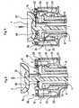
figures 3 et 4 sont des coupes longitudinales respectivement par un plan A et un plan axial B, du premier mode de réalisation de dispositif d'injection conforme à l'invention représenté en perspective auxfigures 1 a et 1 b, - la
figure 5a est une vue en perspective représentant un élément de verrouillage adapté pour équiper un second mode de réalisation d'un dispositif d'injection selon l'invention représenté vu en perspective à lafigure 5b , - les
figures 6 sont des coupes longitudinales respectivement par le plan axial B et le plan A, du second mode de réalisation de dispositif d'injection conforme à l'invention représenté en perspective auxet 7figures 5a et 5b , - les
figures 8 sont deux coupes longitudinales partielles du premier mode de réalisation de dispositif d'injection conforme à l'invention représentant chacune, en demi coupe par le plan A et en demi coupe par le plan B, une des étapes du fonctionnement de ce dispositif d'injection,et 9 - la
figure 10 est une vue longitudinale du premier mode de réalisation de dispositif d'injection conforme à l'invention représentant ce dernier lors de l'étape finale de fin d'injection, - et la
figure 11 est une coupe longitudinale partielle du second mode de réalisation de dispositif d'injection conforme à l'invention représentant, en demi coupe par le plan A et en demi coupe par le plan B, l'étape du fonctionnement de ce dispositif d'injection correspondant à celle représentée à lafigure 8 en référence au premier dispositif d'injection.
- the
figure 1 a is a perspective view showing a locking element adapted to equip a first embodiment of an injection device according to the invention shown in perspective at thefigure 1b , - the
figure 2 is a longitudinal view of a piston rod of an injection device according to the invention, - the
Figures 3 and 4 are longitudinal sections respectively by a plane A and an axial plane B, of the first embodiment of injection device according to the invention shown in perspective atfigures 1 a and 1b, - the
figure 5a is a perspective view showing a locking element adapted to equip a second mode embodiment of an injection device according to the invention shown in perspective at thefigure 5b , - the
Figures 6 and 7 are longitudinal sections respectively by the axial plane B and the plane A, of the second embodiment of injection device according to the invention shown in perspective atFigures 5a and 5b , - the
Figures 8 and 9 are two partial longitudinal sections of the first embodiment of the injection device according to the invention each representing, in half section through the plane A and in half section through the plane B, one of the steps of the operation of this injection device , - the
figure 10 is a longitudinal view of the first embodiment of injection device according to the invention representing the latter during the final stage of end of injection, - and the
figure 11 is a partial longitudinal section of the second embodiment of injection device according to the invention showing, in half section through the plane A and in half section through the plane B, the step of operation of the corresponding injection device to that represented atfigure 8 with reference to the first injection device.
Les deux variantes de dispositifs d'injection selon l'inventton représentés à titre d'exemples aux figures sont du type à usage unique et consistent en des dispositifs d'injection particulièrement adaptés pour l'injection de médicaments requérant une reconstitution (solvant - produit lyophilisé) avant injection, et nécessitant, à cet effet :
- une première vidange destinée à injecter le solvant renfermé dans le dispositif d'injection dans un flacon contenant le produit lyophilisé,
- une aspiration du produit reconstitué en vue du remplissage du dispositif d'injection,
- et l'injection proprement dite du produit médicamenteux.
- a first emptying for injecting the solvent contained in the injection device in a bottle containing the freeze-dried product,
- an aspiration of the reconstituted product for the filling of the injection device,
- and the actual injection of the drug product.
De plus, ces deux variantes de dispositifs d'injection intègrent des dispositifs de protection adaptés pour permettre de protéger leur aiguille d'injection après usage.In addition, these two variants of injection devices incorporate protective devices adapted to allow to protect their injection needle after use.
En premier lieu, chacun de ces dispositifs d'injection comprend un récipient tel qu'en l'exemple une seringue classique 1 constituée d'un tube de verre, d'une part, prolongé d'une embase 2 dans laquelle est scellée une aiguille d'injection 3, et d'autre part, doté d'une collerette externe 4 au niveau de son extrémité opposée à l'embase 2.In the first place, each of these injection devices comprises a container such as, for example, a
De plus, cette seringue 1 est classiquement équipée d'un piston 5 apte à coulisser de façon étanche à l'intérieur de cette dernière, et solidarisé, en vue de son actionnement, sur une extrémité d'une tige de piston 6 dotée, au niveau de son extrémité opposée, d'un bouton poussoir 7 présentant la forme d'une coupelle, c'est-à-dire présentant une face 7a de jonction avec la tige de piston 6, de forme convexe.In addition, this
Tel que précité, ces deux dispositifs d'injection comprennent, en outre, un dispositif de protection après usage de l'aiguille d'injection 3. Selon les deux exemples représentés aux figures, ces deux dispositifs de protection consistent en des dispositifs de même conception de base que celle des dispositifs d'injection commercialisés par la société « SAFETY SYRINGES, Inc.», et décrits notamment dans les demandes de brevet
En premier lieu, le dispositif de protection du premier dispositif d'injection représenté aux
Ce corps de seringue 8 comporte, en outre, une tête tubulaire 11 de prise digitale, ménagée autour du tronçon d'extrémité du conduit longitudinal 9 sur lequel est formée la couronne 10.This
Cette tête tubulaire 11 est formée de deux demi coquilles 12, 13 s'étendant symétriquement de part et d'autre de la couronne et reliées chacune à cette dernière par deux bras parallèles prolongés, chacun, d'une gâchette 16, 17 déformable élastiquement, et adaptés pour que les gâchettes 16, 17 de deux bras coplanaires définissent, avec la face en vis-à-vis de la couronne 10, une lumière 18 de logement et de blocage de la collerette externe 4 de la seringue 1.This
Le dispositif de protection du premier dispositif d'injection conforme à l'invention comprend également un étui de protection 19 adapté pour coulisser extérieurement le long du conduit tubulaire 9 du corps de seringue 8.The protection device of the first injection device according to the invention also comprises a
Cet étui de protection 19 comporte, en premier lieu, deux ailettes de prise digitale 21, 22 disposées et de formes adaptées pour obturer sensiblement la face ouverte en regard de la tête tubulaire 11.This
De plus, cet étui de protection 19 comporte deux doigts de verrouillage 22, 23 agencés pour s'étendre symétriquement de part et d'autre du conduit tubulaire 9, chacun à partir d'une des ailettes de prise digitale 20, 21, et adaptés pour bloquer en translation l'étui de protection 19 relativement au corps de seringue 8, dans une position relative rétractée du dit étui de protection où l'aiguille d'injection 3 dépasse de ce dernier.In addition, this
Chacun de ces doigts de verrouillage 22, 23 se compose d'une lame déformable élastiquement se prolongeant au-delà de la collerette 4 de la seringue 1 bloquée dans les lumières 18, et s'étendant notamment, à cet effet à l'intérieur d'une encoche 24, représentée à la
Chaque lame 22, 23 comporte, en outre, un organe intermédiaire de verrouillage adapté pour venir reposer et se verrouiller sur la couronne 10 de part et d'autre de l'encoche 24 ménagée dans cette dernière, le dit organe de verrouillage consistant en une traverse définissant deux plots de verrouillage 25, 26 s'étendant de part et d'autre de la dite lame.Each
Chaque lame 22, 23 comporte, enfin, un bourrelet 27 ménagé au niveau de son extrémité libre et adapté pour former une face d'appui complémentaire de la face convexe du bouton poussoir 7 de la tige de piston 6, apte a déclencher un déverrouillage des plots de verrouillage 25, 26 par déformation de chaque lame 22, 23 en fin de course de la dite tige de piston 6.Each
L'étui de protection comporte également quatre doigts de verrouillage tels que 28, 29 répartis autour du conduit tubulaire 9, agencés pour s'étendre chacun à partir d'une des ailettes de prise digitale 20, 21, et adaptés pour bloquer en translation l'étui de protection 19 relativement au corps de seringue 8, dans une position relative déployée du dit étui de protection où l'aiguille d'injection 3 est entièrement logée dans ce dernier.The protective case also comprises four locking fingers such as 28, 29 distributed around the
Chacun de ces doigts de verrouillage 28. 29 se compose d'une lame déformable élastiquement, dotée, au niveau de son extrémité libre, d'un ergot de verrouillage 30 adapté pour venir se loger dans un cran 31 ménagé le long du conduit longitudinal 9, et représenté à la
De façon usuelle, le dispositif de protection comporte également un ressort (non représenté) disposé entre le corps de seringue 8 et l'étui de protection 19 et adapté pour entraîner un coulissement relatif des ces derniers en fin d'injection.Usually, the protective device also comprises a spring (not shown) disposed between the
Selon l'invention et, en premier lieu, la tige de piston 6 comporte une collerette 32 ménagée en position intermédiaire de la longueur de la dite tige de piston.According to the invention and, firstly, the
Selon l'invention, en outre, les dispositifs de protection comportent un élément de verrouillage adapté pour collaborer avec la collerette 32 précitée en vue de présenter, de façon automatique, un état apte :
- à interdire le déclenchement du déverrouillage des plots de déverrouillage 25, 26, lors du premier actionnement de la tige de
piston 6 visant à permettre le mélange du produit, - et à autoriser le déclenchement du déverrouillage des plots de déverrouillage 25, 26, lors du second actionnement de la tige de
piston 6 destiné à l'injection du produit.
- to prohibit the triggering of the unlocking of the unlocking
studs piston rod 6 to allow the product to be mixed, - and to authorize the triggering of unlocking of the unlocking
studs piston rod 6 intended for the injection of the product.
Concernant le dispositif de protection du premier mode de réalisation de dispositif d'injection selon l'invention, cet élément de verrouillage 33 est adapté pour s'emboîter à l'intérieur de la tête de prise digitale 11.With regard to the protection device of the first embodiment of the injection device according to the invention, this locking element 33 is adapted to fit inside the
Il comprend une plaque de verrouillage 34 adaptée pour s'étendre sensiblement dans le plan de la face de la tête de prise digitale opposée aux ailes de prise digitale 20, 21, par rapport à laquelle s'étendent quatre pieds tels que 35, 36 adaptés pour s'étendre à l'intérieur de la tête de prise digitale 11, et se terminant par un crochet 37 délimitant une gorge longitudinale 38 adaptée pour loger, avec un jeu de débattement, le rebord de la couronne 10.It comprises a locking
La plaque de verrouillage 34 comprend, en outre, en regard de chaque doigt de verrouillage 22, 23, une découpe en forme de U 39 définissant deux branches parallèles 40, 41 adaptées pour se positionner en butée chacune contre un plot de verrouillage 25, 26.The locking
En vue de parfaire le verrouillage des doigts de verrouillage 22, 23, la face d'extrémité de chaque branche 40, 41 présente, en outre, la forme d'un ergot 42 adapté pour se loger dans un cran 43 de forme complémentaire ménagé dans la face en regard de chaque plot de verrouillage 25,26.In order to perfect the locking of the locking
Cette plaque de verrouillage 34 comprend, en outre, associé à chaque doigt de verrouillage 22, 23, un levier 44 articulé autour d'un axe de pivotement 45 orthogonal à l'axe longitudinal du corps de seringue 8, le dit levier comportant :
- s'étendant sur un des côtés de l'axe de pivotement 45, une
pièce plane 46 de butée de la collerette intermédiaire 32 de la tige depiston 6, ménagée de façon à être située sur la trajectoire de la dite collerette, la dite pièce de butée présentant, en outre,un bord libre 46a biseauté apte à faciliter le passage de la collerette 32 lors d'un déplacement dupiston 5 dans le sens de la vidange de la seringue 1, - et s'étendant de l'autre côté de l'axe de pivotement 45, deux branches parallèles 47, 48 chacune adaptée pour venir en appui, au niveau de son extrémité libre, sur un plot de verrouillage 25, 26.
- extending on one of the sides of the
pivot axis 45, aflat abutment piece 46 of theintermediate flange 32 of thepiston rod 6, arranged so as to be situated in the path of said collar, said piece abutment having, in addition, afree edge 46a beveled capable of facilitating the passage of theflange 32 during a displacement of thepiston 5 in the direction of the emptying of thesyringe 1, - and extending on the other side of the
pivot axis 45, twoparallel branches locking pin
Le fonctionnement de ce premier dispositif d'injection est décrit ci-dessous en référence aux
Dans la position initiale du dispositif d'injection représentée aux
Cet élément de verrouillage 33 se trouve ainsi dans une position dite de désactivation dans laquelle il interdit tout écartement relatif des doigts de verrouillage 22, 23, et par conséquent tout déverrouillage des dits doigts de verrouillage.This locking element 33 is thus in a so-called deactivation position in which it prevents any relative spacing of the locking
Le premier actionnement du piston 5 visant à vidanger la seringue en vue du mélange du solvant et du produit lyophilisé, n'engendre aucune modification de la position de l'élément de verrouillage 33 : le passage par la collerette intermédiaire 32 de la tige de piston 6 de l'obstacle que constitue la pièce de butée 46 n'engendre, en effet, qu'un basculement sans conséquence du levier 44.The first actuation of the
Par contre, tel que représenté à la
De ce fait, et tel que représenté à la
Le dispositif de protection du second mode de réalisation de dispositif d'injection conforme à l'invention représenté aux
Les seules différences marquantes sont relatives aux organes de verrouillage adaptés pour bloquer en translation l'étui de protection 19 relativement au corps de seringue 8 dans la position relative déployée du dit étui de protection où l'aiguille d'injection 3 est entièrement logée dans ce dernier.The only significant differences are relative to the locking members adapted to lock in translation the
Selon ce mode de réalisation, en effet ces organes de verrouillage comprennent :
- une lumière 30' ménagée dans la paroi périphérique de la tête de prise digitale 11,
- et un cran 31' formé sur le conduit longitudinal 9 du corps de seringue 8, vers l'extrémité libre de ce dernier.
- a light 30 'formed in the peripheral wall of the
digital capture head 11, - and a notch 31 'formed on the
longitudinal conduit 9 of thesyringe body 8 towards the free end thereof.
De même, la tige de piston 6 est similaire à celle ci-dessus décrite et représentée à la
La différence essentielle entre ces deux modes de réalisation concerne l'élément de verrouillage.The essential difference between these two embodiments concerns the locking element.
Selon le second mode de réalisation, l'élément de verrouillage 51 est adapté pour coiffer la tête de prise digitale 11.According to the second embodiment, the locking
Il comprend une plaque de verrouillage 52 adaptée pour s'étendre sensiblement dans le plan de la face de la tête de prise digitale 11 opposée aux ailes de prise digitale 20, 21, par rapport à laquelle s'étend une jupe 53 adaptée pour coiffer les deux demi coquilles 12, 13.It comprises a locking
De plus, cet élément de verrouillage 51 comporte des ergots tels que 54 ménagés en saillie par rapport à la face interne de la jupe 53 et adaptés pour s'encliqueter sans jeu sous les bras 14, 15 de la tête tubulaire 11.In addition, this locking
Cet élément de verrouillage 51 comprend, en outre, associé à chaque doigt de verrouillage 22, 23, une pièce de verrouillage 55 disposée à l'intérieur de la jupe 53, la dite pièce de verrouillage présentant une élasticité propre et étant reliée à la jupe 53 par une liaison telles qu'elle présente une faculté de déformation élastique.This locking
Cette pièce de verrouillage 55 comporte :
un cadre 56 définissant une ouverture pour le passage d'un des doigts de verrouillage 22, 23, le dit cadre comportant, en outre, une traverse 57 de butée de la collerette intermédiaire 32 de la tige depiston 6, ménagée de façon à être située sur la trajectoire de la dite collerette, la dite traverse de butée présentant, en outre,un bord libre 57a biseauté apte à faciliter le passage de la collerette 32, lors d'un déplacement dupiston 5 dans le sens de la vidange de la seringue 1,deux branches cadre 56 perpendiculaire à latraverse 57, de façon à se positionner en butée chacune contre un plot de verrouillage 25, 26 des doigts de verrouillage 22, 23, les dites branches présentant une face d'extrémitéformant un ergot 60 adapté pour se loger dans le cran 43 du plot de verrouillage 25, 26 en vis à vis.
- a
frame 56 defining an opening for the passage of one of the lockingfingers crossmember 57 for abutment of theintermediate collar 32 of thepiston rod 6, arranged so as to be located in the path of said collar, said stop cross member further having afree edge 57a beveled to facilitate the passage of theflange 32, during a displacement of thepiston 5 in the direction of the draining of thesyringe 1, - two
branches frame 56 perpendicular to thecrosspiece 57, so as to be positioned in abutment each against a lockingstud fingers lug 60 adapted to be housed in thenotch 43 of the lockingstud
Selon ce principe l'élément de verrouillage 51 est fixé sans jeu sur la tête de prise digitale 11, et se trouve initialement positionné, tel que représenté aux
Cet élément de verrouillage 51 se trouve ainsi dans une position de désactivation dans laquelle il interdit tout écartement relatif des doigts de verrouillage 22, 23, et par conséquent tout déverrouillage des dits doigts de verrouillage.This locking
Tel que précédemment, le premier actionnement du piston 5 visant à vidanger la seringue n'engendre aucune modification de la position de l'élément de verrouillage.As previously, the first actuation of the
Par contre, tel que représenté à la
Moyennant l'adjonction d'un simple élément de verrouillage, l'invention conduit donc à transformer un dispositif d'injection sécurisé à usage unique en un dispositif d'injection sécurisé permettant, sans nécessiter une quelconque action spécifique de l'utilisateur, un premier actionnement du piston, puis l'injection proprement dite accompagnée de la sécurisation.With the addition of a simple locking element, the invention thus leads to converting a disposable secure injection device into a secure injection device which, without requiring any specific action by the user, first actuation of the piston, then the actual injection accompanied by securing.
Claims (6)
- Safety device for injecting a medicinal product such as a lyophilized product, comprising a syringe body (8) with a receptacle (1) which has an injection needle (3) and equipped with a plunger (5) actuated by a plunger rod (6) equipped with a push-button (7), and a protection device comprising:- a protective casing (19) adapted so that said protective casing and the syringe body (8) are able to slide relatively one in relation to the other between an injection position in which the injection needle (3) extends at least partially into the extension of the protective casing (19), and a protection position after use in which the injection needle (3) is completely accommodated in the protective casing (19),- at least one locking member (22, 23) which can have a locked state for holding the syringe body (8) and the protective casing (19) in their injection position, and for switching to an unlocked state which can allow, at the end of the movement of the plunger (5) inside the receptacle (1), the relative sliding of the syringe body (8) and the protective casing (19) to their protection position after use,- a shoulder (32) placed in an intermediate position of the length of the plunger rod (6), and- a locking member (33; 51) attached on one of the members, syringe body (8) or protective casing (19),
said injection device beingcharacterised in that the locking member comprises:- blocking devices (40, 41; 58; 59) locking members (22, 23) that can be displaced between a natural initial position, called the deactivation position, of blocking each locking member (22, 23) in its locked state, and a position, called the activation position, which allows each locking member (22, 23) to be switched to its unlocked state,- and actuating members (44; 57) connected to the blocking devices (40, 41; 58; 59), positioned on the trajectory of the intermediate shoulder (32) of the plunger rod (6), and adapted to undergo a change of state bringing about a displacement of said blocking devices from their deactivation position to their activation position, when a force is exerted on said actuating members by the intermediate shoulder (32), during a displacement of the plunger rod (6) resulting from a tension exerted on the push-button (7). - Injection device according to claim 1,characterised in that:- the locking member (33) is attached on one of the members, syringe body (8) or protective casing (19), with an ability of movement according to a direction parallel to the longitudinal axis of the protection device, between two positions defining the respective positions of deactivation and activation of the blocking devices (40, 41) of the locking members (22, 23),- the actuating members comprise at least one lever (44) articulated on the locking member (33) around a rotation axis (45) and comprising, extending on both sides of said rotation axis:- a contact area (46) situated on the trajectory of the intermediate shoulder (32) of the plunger rod (6),- and at least one buttressing part (47, 48) which can bring about a movement of the locking member (33) resulting in a displacement of the blocking devices (40, 41) from their deactivation position to their activation position, during a rotation of the lever (44) caused by the displacement of the plunger rod (6) resulting from a tension exerted on the push-button (7).
- Injection device according to claim 1,characterised in that:- the locking member (51) is attached in a fixed position on one of the members, syringe body (8) or protective casing (19),- the actuating members comprise at least one locking part (55) integral with the locking member (51), comprising in a single piece- a contact area (57) situated on the trajectory of the intermediate shoulder (32) of the plunger rod (6),- at least one blocking device (58, 59) of one locking member (22, 23),- and a deformable area (56) of connection between the contact area (57) and each blocking device (58; 59) which can deform and bring about a displacement of each blocking device (58; 59) from its deactivation position to its activation position, when a force is exerted on the contact area (57) by the intermediate shoulder (32) during a displacement of the plunger rod (6) resulting from a tension exerted on the push-button (7).
- Injection device according to any one of the preceding claims,characterised in that the locking member (33; 51) is attached on the syringe body (8).
- Injection device according to any one of the preceding claims,characterised in that the blocking devices (40, 41; 58; 59) of the locking member (33; 51) and the locking members (22, 23) for holding the syringe body (8) and the protective casing (19) in their injection position, comprise additional removable assembly members (42, 43; 60, 43) of the catch/pin type.
- Injection device according to any one of the preceding claims, in which the locking members (22, 23), for holding the syringe body (8) and the protective casing (19) in their injection position, consist of flexible strips,characterised in that the blocking devices (40, 41; 58; 59) of said locking members, are adapted to prevent, in their deactivation position, the deformation of the latter by bending.
Applications Claiming Priority (2)
| Application Number | Priority Date | Filing Date | Title |
|---|---|---|---|
| US81407106P | 2006-06-16 | 2006-06-16 | |
| PCT/FR2007/000979WO2007144507A1 (en) | 2006-06-16 | 2007-06-13 | Safety device for injecting a medicinal product, such as a lyophilized product |
Publications (2)
| Publication Number | Publication Date |
|---|---|
| EP2029202A1 EP2029202A1 (en) | 2009-03-04 |
| EP2029202B1true EP2029202B1 (en) | 2013-12-25 |
Family
ID=38478566
Family Applications (1)
| Application Number | Title | Priority Date | Filing Date |
|---|---|---|---|
| EP07788884.0AActiveEP2029202B1 (en) | 2006-06-16 | 2007-06-13 | Safety device for injecting a medicinal product, such as a lyophilized product |
Country Status (3)
| Country | Link |
|---|---|
| US (1) | US20090270803A1 (en) |
| EP (1) | EP2029202B1 (en) |
| WO (1) | WO2007144507A1 (en) |
Families Citing this family (8)
| Publication number | Priority date | Publication date | Assignee | Title |
|---|---|---|---|---|
| US8105292B2 (en) | 2008-02-11 | 2012-01-31 | Safety Syringes, Inc. | Reconstitution means for safety device |
| EP2623145A1 (en)* | 2012-02-03 | 2013-08-07 | Q Stat Pty Ltd | Retractable needle apparatus |
| US9248242B2 (en)* | 2012-04-20 | 2016-02-02 | Safety Syringes, Inc. | Anti-needle stick safety device for injection device |
| EP2752211A1 (en)* | 2013-01-07 | 2014-07-09 | F. Hoffmann-La Roche Ltd. | Safety device for an injection syringue |
| US20150367083A1 (en)* | 2013-02-06 | 2015-12-24 | Weibel Cds Ag | Dispensing device for dispensing a fluid |
| WO2014153599A1 (en) | 2013-03-25 | 2014-10-02 | Adam Timothy John | Auto-retractible syringe |
| FR3038840B1 (en)* | 2015-07-16 | 2017-07-21 | Nemera La Verpilliere | SAFETY DEVICE FOR INJECTION SYRINGE. |
| US10675416B2 (en)* | 2018-08-17 | 2020-06-09 | David Harold Kovacs | Retractable syringe |
Family Cites Families (6)
| Publication number | Priority date | Publication date | Assignee | Title |
|---|---|---|---|---|
| DK0467173T3 (en)* | 1990-07-19 | 1996-03-11 | Nardino Righi | Disposable Safety Syringe |
| IT1253104B (en)* | 1991-07-02 | 1995-07-10 | Paolo Romagnoli | DISPOSABLE SYRINGE |
| AUPR373001A0 (en)* | 2001-03-14 | 2001-04-12 | Glenord Pty Ltd | Improved non-reusable syringe |
| FR2835753B1 (en)* | 2002-02-11 | 2004-10-29 | Plastef Investissements | SAFETY SUPPORT DEVICE FOR A SYRINGE AND ASSEMBLY OF SUCH A DEVICE AND A SYRINGE |
| FR2861310B1 (en)* | 2003-10-22 | 2006-09-22 | Plastef Investissements | SECURE INJECTION SYRINGE DEVICE |
| FR2876035B1 (en)* | 2003-11-14 | 2007-03-30 | Plastic Omnium Cie | SAFETY ASSEMBLY FOR EQUIPPING A SYRINGE AND SYRINGE ASSEMBLY |
- 2007
- 2007-06-13EPEP07788884.0Apatent/EP2029202B1/enactiveActive
- 2007-06-13USUS12/304,705patent/US20090270803A1/ennot_activeAbandoned
- 2007-06-13WOPCT/FR2007/000979patent/WO2007144507A1/enactiveApplication Filing
Also Published As
| Publication number | Publication date |
|---|---|
| WO2007144507A1 (en) | 2007-12-21 |
| US20090270803A1 (en) | 2009-10-29 |
| EP2029202A1 (en) | 2009-03-04 |
Similar Documents
| Publication | Publication Date | Title |
|---|---|---|
| EP2029202B1 (en) | Safety device for injecting a medicinal product, such as a lyophilized product | |
| EP1218047B1 (en) | Disposable injection device | |
| EP1148904B1 (en) | Safety assembly for a syringe pre-filled with liquid, in particular a medicine | |
| EP1053037B1 (en) | Device for automatic injection of a dose of medicinal product | |
| EP1530979B1 (en) | Security assembly for a syringe device | |
| EP1224000B1 (en) | Safety device for injection syringe | |
| EP1235603B1 (en) | Safety system for a syringe | |
| EP1628695B1 (en) | Pre-filled syringe with anti-tamper cap | |
| FR2794650A1 (en) | INJECTION DEVICE FOR SINGLE USE | |
| EP1330279B1 (en) | Injection syringe with mobile needle guard | |
| WO2003033059A1 (en) | Safety device for a syringe | |
| WO1991013643A1 (en) | Syringe with self-retracting needle | |
| WO1989000432A2 (en) | Non reusable high-security syringe | |
| EP1224001B1 (en) | Disposable hypodermic syringe with locking protective sheath | |
| EP3659652A1 (en) | Device for removal of needle cap protection | |
| EP1372772B1 (en) | Syringe with improved safety | |
| WO2010012876A2 (en) | Single-use safe injection device | |
| WO2012110715A1 (en) | Safety single-use injection device | |
| EP1368081B1 (en) | Syringe | |
| FR2720001A1 (en) | Medical injection syringe |
Legal Events
| Date | Code | Title | Description |
|---|---|---|---|
| PUAI | Public reference made under article 153(3) epc to a published international application that has entered the european phase | Free format text:ORIGINAL CODE: 0009012 | |
| 17P | Request for examination filed | Effective date:20081231 | |
| AK | Designated contracting states | Kind code of ref document:A1 Designated state(s):AT BE BG CH CY CZ DE DK EE ES FI FR GB GR HU IE IS IT LI LT LU LV MC MT NL PL PT RO SE SI SK TR | |
| AX | Request for extension of the european patent | Extension state:AL BA HR MK RS | |
| 111L | Licence recorded | Free format text:0101 PLASTEF INVESTISSEMENTS Effective date:20100310 | |
| 17Q | First examination report despatched | Effective date:20110629 | |
| DAX | Request for extension of the european patent (deleted) | ||
| GRAP | Despatch of communication of intention to grant a patent | Free format text:ORIGINAL CODE: EPIDOSNIGR1 | |
| INTG | Intention to grant announced | Effective date:20130709 | |
| GRAS | Grant fee paid | Free format text:ORIGINAL CODE: EPIDOSNIGR3 | |
| GRAA | (expected) grant | Free format text:ORIGINAL CODE: 0009210 | |
| 111L | Licence recorded | Designated state(s):AT BE BG CH CY CZ DE DK EE ES FI FR GB GR HU IE IS IT LT LU LV MC MT NL PL PT RO SE SI SK TR Free format text:EXCLUSIVE LICENSE Name of requester:PLASTEF INVESTISSEMENTS, FR Effective date:20100310 | |
| AK | Designated contracting states | Kind code of ref document:B1 Designated state(s):AT BE BG CH CY CZ DE DK EE ES FI FR GB GR HU IE IS IT LI LT LU LV MC MT NL PL PT RO SE SI SK TR | |
| REG | Reference to a national code | Ref country code:GB Ref legal event code:FG4D Free format text:NOT ENGLISH | |
| REG | Reference to a national code | Ref country code:CH Ref legal event code:EP Ref country code:CH Ref legal event code:PK Free format text:COMPLEMENT D'ENREGISTREMENT DE LICENCE: LICENCE EXCLUSIVE | |
| REG | Reference to a national code | Ref country code:AT Ref legal event code:REF Ref document number:646229 Country of ref document:AT Kind code of ref document:T Effective date:20140115 | |
| REG | Reference to a national code | Ref country code:IE Ref legal event code:FG4D Free format text:LANGUAGE OF EP DOCUMENT: FRENCH | |
| REG | Reference to a national code | Ref country code:DE Ref legal event code:R096 Ref document number:602007034467 Country of ref document:DE Effective date:20140220 | |
| PG25 | Lapsed in a contracting state [announced via postgrant information from national office to epo] | Ref country code:SE Free format text:LAPSE BECAUSE OF FAILURE TO SUBMIT A TRANSLATION OF THE DESCRIPTION OR TO PAY THE FEE WITHIN THE PRESCRIBED TIME-LIMIT Effective date:20131225 Ref country code:LT Free format text:LAPSE BECAUSE OF FAILURE TO SUBMIT A TRANSLATION OF THE DESCRIPTION OR TO PAY THE FEE WITHIN THE PRESCRIBED TIME-LIMIT Effective date:20131225 Ref country code:FI Free format text:LAPSE BECAUSE OF FAILURE TO SUBMIT A TRANSLATION OF THE DESCRIPTION OR TO PAY THE FEE WITHIN THE PRESCRIBED TIME-LIMIT Effective date:20131225 | |
| REG | Reference to a national code | Ref country code:NL Ref legal event code:VDEP Effective date:20131225 | |
| REG | Reference to a national code | Ref country code:AT Ref legal event code:MK05 Ref document number:646229 Country of ref document:AT Kind code of ref document:T Effective date:20131225 | |
| REG | Reference to a national code | Ref country code:LT Ref legal event code:MG4D | |
| PG25 | Lapsed in a contracting state [announced via postgrant information from national office to epo] | Ref country code:LV Free format text:LAPSE BECAUSE OF FAILURE TO SUBMIT A TRANSLATION OF THE DESCRIPTION OR TO PAY THE FEE WITHIN THE PRESCRIBED TIME-LIMIT Effective date:20131225 | |
| PG25 | Lapsed in a contracting state [announced via postgrant information from national office to epo] | Ref country code:EE Free format text:LAPSE BECAUSE OF FAILURE TO SUBMIT A TRANSLATION OF THE DESCRIPTION OR TO PAY THE FEE WITHIN THE PRESCRIBED TIME-LIMIT Effective date:20131225 Ref country code:IS Free format text:LAPSE BECAUSE OF FAILURE TO SUBMIT A TRANSLATION OF THE DESCRIPTION OR TO PAY THE FEE WITHIN THE PRESCRIBED TIME-LIMIT Effective date:20140425 | |
| PG25 | Lapsed in a contracting state [announced via postgrant information from national office to epo] | Ref country code:CY Free format text:LAPSE BECAUSE OF FAILURE TO SUBMIT A TRANSLATION OF THE DESCRIPTION OR TO PAY THE FEE WITHIN THE PRESCRIBED TIME-LIMIT Effective date:20131225 Ref country code:SK Free format text:LAPSE BECAUSE OF FAILURE TO SUBMIT A TRANSLATION OF THE DESCRIPTION OR TO PAY THE FEE WITHIN THE PRESCRIBED TIME-LIMIT Effective date:20131225 Ref country code:RO Free format text:LAPSE BECAUSE OF FAILURE TO SUBMIT A TRANSLATION OF THE DESCRIPTION OR TO PAY THE FEE WITHIN THE PRESCRIBED TIME-LIMIT Effective date:20131225 Ref country code:ES Free format text:LAPSE BECAUSE OF FAILURE TO SUBMIT A TRANSLATION OF THE DESCRIPTION OR TO PAY THE FEE WITHIN THE PRESCRIBED TIME-LIMIT Effective date:20131225 Ref country code:PL Free format text:LAPSE BECAUSE OF FAILURE TO SUBMIT A TRANSLATION OF THE DESCRIPTION OR TO PAY THE FEE WITHIN THE PRESCRIBED TIME-LIMIT Effective date:20131225 Ref country code:CZ Free format text:LAPSE BECAUSE OF FAILURE TO SUBMIT A TRANSLATION OF THE DESCRIPTION OR TO PAY THE FEE WITHIN THE PRESCRIBED TIME-LIMIT Effective date:20131225 Ref country code:AT Free format text:LAPSE BECAUSE OF FAILURE TO SUBMIT A TRANSLATION OF THE DESCRIPTION OR TO PAY THE FEE WITHIN THE PRESCRIBED TIME-LIMIT Effective date:20131225 Ref country code:PT Free format text:LAPSE BECAUSE OF FAILURE TO SUBMIT A TRANSLATION OF THE DESCRIPTION OR TO PAY THE FEE WITHIN THE PRESCRIBED TIME-LIMIT Effective date:20140428 Ref country code:NL Free format text:LAPSE BECAUSE OF FAILURE TO SUBMIT A TRANSLATION OF THE DESCRIPTION OR TO PAY THE FEE WITHIN THE PRESCRIBED TIME-LIMIT Effective date:20131225 | |
| REG | Reference to a national code | Ref country code:DE Ref legal event code:R097 Ref document number:602007034467 Country of ref document:DE | |
| PG25 | Lapsed in a contracting state [announced via postgrant information from national office to epo] | Ref country code:DK Free format text:LAPSE BECAUSE OF FAILURE TO SUBMIT A TRANSLATION OF THE DESCRIPTION OR TO PAY THE FEE WITHIN THE PRESCRIBED TIME-LIMIT Effective date:20131225 | |
| PLBE | No opposition filed within time limit | Free format text:ORIGINAL CODE: 0009261 | |
| STAA | Information on the status of an ep patent application or granted ep patent | Free format text:STATUS: NO OPPOSITION FILED WITHIN TIME LIMIT | |
| 26N | No opposition filed | Effective date:20140926 | |
| REG | Reference to a national code | Ref country code:DE Ref legal event code:R097 Ref document number:602007034467 Country of ref document:DE Effective date:20140926 | |
| PG25 | Lapsed in a contracting state [announced via postgrant information from national office to epo] | Ref country code:LU Free format text:LAPSE BECAUSE OF FAILURE TO SUBMIT A TRANSLATION OF THE DESCRIPTION OR TO PAY THE FEE WITHIN THE PRESCRIBED TIME-LIMIT Effective date:20140613 Ref country code:MC Free format text:LAPSE BECAUSE OF FAILURE TO SUBMIT A TRANSLATION OF THE DESCRIPTION OR TO PAY THE FEE WITHIN THE PRESCRIBED TIME-LIMIT Effective date:20131225 | |
| REG | Reference to a national code | Ref country code:CH Ref legal event code:PL | |
| GBPC | Gb: european patent ceased through non-payment of renewal fee | Effective date:20140613 | |
| REG | Reference to a national code | Ref country code:IE Ref legal event code:MM4A | |
| PG25 | Lapsed in a contracting state [announced via postgrant information from national office to epo] | Ref country code:IE Free format text:LAPSE BECAUSE OF NON-PAYMENT OF DUE FEES Effective date:20140613 Ref country code:CH Free format text:LAPSE BECAUSE OF NON-PAYMENT OF DUE FEES Effective date:20140630 Ref country code:LI Free format text:LAPSE BECAUSE OF NON-PAYMENT OF DUE FEES Effective date:20140630 | |
| PG25 | Lapsed in a contracting state [announced via postgrant information from national office to epo] | Ref country code:SI Free format text:LAPSE BECAUSE OF FAILURE TO SUBMIT A TRANSLATION OF THE DESCRIPTION OR TO PAY THE FEE WITHIN THE PRESCRIBED TIME-LIMIT Effective date:20131225 Ref country code:GB Free format text:LAPSE BECAUSE OF NON-PAYMENT OF DUE FEES Effective date:20140613 | |
| PG25 | Lapsed in a contracting state [announced via postgrant information from national office to epo] | Ref country code:MT Free format text:LAPSE BECAUSE OF FAILURE TO SUBMIT A TRANSLATION OF THE DESCRIPTION OR TO PAY THE FEE WITHIN THE PRESCRIBED TIME-LIMIT Effective date:20131225 | |
| REG | Reference to a national code | Ref country code:FR Ref legal event code:PLFP Year of fee payment:10 | |
| PG25 | Lapsed in a contracting state [announced via postgrant information from national office to epo] | Ref country code:BG Free format text:LAPSE BECAUSE OF FAILURE TO SUBMIT A TRANSLATION OF THE DESCRIPTION OR TO PAY THE FEE WITHIN THE PRESCRIBED TIME-LIMIT Effective date:20131225 | |
| PG25 | Lapsed in a contracting state [announced via postgrant information from national office to epo] | Ref country code:GR Free format text:LAPSE BECAUSE OF FAILURE TO SUBMIT A TRANSLATION OF THE DESCRIPTION OR TO PAY THE FEE WITHIN THE PRESCRIBED TIME-LIMIT Effective date:20140326 Ref country code:IT Free format text:LAPSE BECAUSE OF FAILURE TO SUBMIT A TRANSLATION OF THE DESCRIPTION OR TO PAY THE FEE WITHIN THE PRESCRIBED TIME-LIMIT Effective date:20131225 | |
| PG25 | Lapsed in a contracting state [announced via postgrant information from national office to epo] | Ref country code:BE Free format text:LAPSE BECAUSE OF FAILURE TO SUBMIT A TRANSLATION OF THE DESCRIPTION OR TO PAY THE FEE WITHIN THE PRESCRIBED TIME-LIMIT Effective date:20140630 Ref country code:HU Free format text:LAPSE BECAUSE OF FAILURE TO SUBMIT A TRANSLATION OF THE DESCRIPTION OR TO PAY THE FEE WITHIN THE PRESCRIBED TIME-LIMIT; INVALID AB INITIO Effective date:20070613 Ref country code:TR Free format text:LAPSE BECAUSE OF FAILURE TO SUBMIT A TRANSLATION OF THE DESCRIPTION OR TO PAY THE FEE WITHIN THE PRESCRIBED TIME-LIMIT Effective date:20131225 | |
| REG | Reference to a national code | Ref country code:FR Ref legal event code:PLFP Year of fee payment:11 | |
| REG | Reference to a national code | Ref country code:FR Ref legal event code:PLFP Year of fee payment:12 | |
| REG | Reference to a national code | Ref country code:DE Ref legal event code:R082 Ref document number:602007034467 Country of ref document:DE Representative=s name:WUNDERLICH & HEIM PATENTANWAELTE PARTNERSCHAFT, DE | |
| PGFP | Annual fee paid to national office [announced via postgrant information from national office to epo] | Ref country code:DE Payment date:20250627 Year of fee payment:19 | |
| PGFP | Annual fee paid to national office [announced via postgrant information from national office to epo] | Ref country code:FR Payment date:20250625 Year of fee payment:19 |