EP2029053B1 - A system for altering the geometry of the heart - Google Patents
A system for altering the geometry of the heartDownload PDFInfo
- Publication number
- EP2029053B1 EP2029053B1EP07722712AEP07722712AEP2029053B1EP 2029053 B1EP2029053 B1EP 2029053B1EP 07722712 AEP07722712 AEP 07722712AEP 07722712 AEP07722712 AEP 07722712AEP 2029053 B1EP2029053 B1EP 2029053B1
- Authority
- EP
- European Patent Office
- Prior art keywords
- papillary
- annuloplasty ring
- heart
- tension members
- annulus
- Prior art date
- Legal status (The legal status is an assumption and is not a legal conclusion. Google has not performed a legal analysis and makes no representation as to the accuracy of the status listed.)
- Not-in-force
Links
- 210000003540papillary muscleAnatomy0.000claimsabstractdescription88
- 210000002837heart atriumAnatomy0.000claimsabstractdescription51
- 238000010009beatingMethods0.000claimsabstractdescription17
- 238000004873anchoringMethods0.000claimsdescription12
- 238000005520cutting processMethods0.000claimsdescription11
- 230000001746atrial effectEffects0.000claimsdescription8
- 210000003205muscleAnatomy0.000abstract1
- 230000002861ventricularEffects0.000description31
- 238000000034methodMethods0.000description22
- 210000004115mitral valveAnatomy0.000description19
- 206010027727Mitral valve incompetenceDiseases0.000description10
- 210000005240left ventricleAnatomy0.000description10
- 230000004217heart functionEffects0.000description7
- 239000008280bloodSubstances0.000description6
- 210000004369bloodAnatomy0.000description6
- 210000003709heart valveAnatomy0.000description6
- 230000000302ischemic effectEffects0.000description6
- 210000005246left atriumAnatomy0.000description6
- 238000001356surgical procedureMethods0.000description6
- 238000003780insertionMethods0.000description5
- 230000037431insertionEffects0.000description5
- 230000007246mechanismEffects0.000description5
- 210000001519tissueAnatomy0.000description5
- 239000000560biocompatible materialSubstances0.000description4
- 210000000038chestAnatomy0.000description4
- 230000003680myocardial damageEffects0.000description4
- 230000033764rhythmic processEffects0.000description4
- 210000000591tricuspid valveAnatomy0.000description4
- 238000006073displacement reactionMethods0.000description3
- 239000000463materialSubstances0.000description3
- 230000008439repair processEffects0.000description3
- RTAQQCXQSZGOHL-UHFFFAOYSA-NTitaniumChemical compound[Ti]RTAQQCXQSZGOHL-UHFFFAOYSA-N0.000description2
- 230000009471actionEffects0.000description2
- 239000012620biological materialSubstances0.000description2
- 210000005242cardiac chamberAnatomy0.000description2
- 125000004122cyclic groupChemical group0.000description2
- 230000006870functionEffects0.000description2
- 238000002513implantationMethods0.000description2
- 230000001965increasing effectEffects0.000description2
- HLXZNVUGXRDIFK-UHFFFAOYSA-Nnickel titaniumChemical compound[Ti].[Ti].[Ti].[Ti].[Ti].[Ti].[Ti].[Ti].[Ti].[Ti].[Ti].[Ni].[Ni].[Ni].[Ni].[Ni].[Ni].[Ni].[Ni].[Ni].[Ni].[Ni].[Ni].[Ni].[Ni]HLXZNVUGXRDIFK-UHFFFAOYSA-N0.000description2
- 229910001000nickel titaniumInorganic materials0.000description2
- 231100000773point of departureToxicity0.000description2
- 229920000728polyesterPolymers0.000description2
- 229920001296polysiloxanePolymers0.000description2
- 210000005241right ventricleAnatomy0.000description2
- 238000002560therapeutic procedureMethods0.000description2
- 229910052719titaniumInorganic materials0.000description2
- 239000010936titaniumSubstances0.000description2
- 206010003211Arteriosclerosis coronary arteryDiseases0.000description1
- 0C*1C2(C3C)C1(*1)C1C1(*)C2C3(*(*)=C)/C(/C)=C(/C)\CC*1Chemical compoundC*1C2(C3C)C1(*1)C1C1(*)C2C3(*(*)=C)/C(/C)=C(/C)\CC*10.000description1
- 206010011091Coronary artery thrombosisDiseases0.000description1
- 208000010496Heart ArrestDiseases0.000description1
- 241001465754MetazoaSpecies0.000description1
- 208000011682Mitral valve diseaseDiseases0.000description1
- 239000004743PolypropyleneSubstances0.000description1
- 210000003484anatomyAnatomy0.000description1
- 210000001765aortic valveAnatomy0.000description1
- 238000013459approachMethods0.000description1
- 230000017531blood circulationEffects0.000description1
- 230000000747cardiac effectEffects0.000description1
- 230000002612cardiopulmonary effectEffects0.000description1
- 239000000470constituentSubstances0.000description1
- 208000029078coronary artery diseaseDiseases0.000description1
- 208000026758coronary atherosclerosisDiseases0.000description1
- 208000002528coronary thrombosisDiseases0.000description1
- 238000012937correctionMethods0.000description1
- 230000034994deathEffects0.000description1
- 231100000517deathToxicity0.000description1
- 238000011161developmentMethods0.000description1
- 238000010586diagramMethods0.000description1
- 230000010339dilationEffects0.000description1
- 230000003292diminished effectEffects0.000description1
- 238000009826distributionMethods0.000description1
- 230000000694effectsEffects0.000description1
- 230000002708enhancing effectEffects0.000description1
- 230000007774longtermEffects0.000description1
- 238000004519manufacturing processMethods0.000description1
- 230000003387muscularEffects0.000description1
- 230000002107myocardial effectEffects0.000description1
- 208000010125myocardial infarctionDiseases0.000description1
- 208000031225myocardial ischemiaDiseases0.000description1
- 210000004165myocardiumAnatomy0.000description1
- 229920001778nylonPolymers0.000description1
- 230000002085persistent effectEffects0.000description1
- 230000000144pharmacologic effectEffects0.000description1
- 230000035479physiological effects, processes and functionsEffects0.000description1
- -1polypropylenePolymers0.000description1
- 229920001155polypropylenePolymers0.000description1
- 230000008569processEffects0.000description1
- 230000000750progressive effectEffects0.000description1
- 230000000306recurrent effectEffects0.000description1
- 230000009467reductionEffects0.000description1
- 238000007634remodelingMethods0.000description1
- 230000000250revascularizationEffects0.000description1
- 210000005245right atriumAnatomy0.000description1
- 231100000241scarToxicity0.000description1
- 238000009958sewingMethods0.000description1
- 238000004513sizingMethods0.000description1
- 230000006641stabilisationEffects0.000description1
- 238000011105stabilizationMethods0.000description1
- 230000003313weakening effectEffects0.000description1
Images


Classifications
- A—HUMAN NECESSITIES
- A61—MEDICAL OR VETERINARY SCIENCE; HYGIENE
- A61F—FILTERS IMPLANTABLE INTO BLOOD VESSELS; PROSTHESES; DEVICES PROVIDING PATENCY TO, OR PREVENTING COLLAPSING OF, TUBULAR STRUCTURES OF THE BODY, e.g. STENTS; ORTHOPAEDIC, NURSING OR CONTRACEPTIVE DEVICES; FOMENTATION; TREATMENT OR PROTECTION OF EYES OR EARS; BANDAGES, DRESSINGS OR ABSORBENT PADS; FIRST-AID KITS
- A61F2/00—Filters implantable into blood vessels; Prostheses, i.e. artificial substitutes or replacements for parts of the body; Appliances for connecting them with the body; Devices providing patency to, or preventing collapsing of, tubular structures of the body, e.g. stents
- A61F2/02—Prostheses implantable into the body
- A61F2/24—Heart valves ; Vascular valves, e.g. venous valves; Heart implants, e.g. passive devices for improving the function of the native valve or the heart muscle; Transmyocardial revascularisation [TMR] devices; Valves implantable in the body
- A61F2/2442—Annuloplasty rings or inserts for correcting the valve shape; Implants for improving the function of a native heart valve
- A61F2/2445—Annuloplasty rings in direct contact with the valve annulus
- A—HUMAN NECESSITIES
- A61—MEDICAL OR VETERINARY SCIENCE; HYGIENE
- A61B—DIAGNOSIS; SURGERY; IDENTIFICATION
- A61B17/00—Surgical instruments, devices or methods
- A61B17/04—Surgical instruments, devices or methods for suturing wounds; Holders or packages for needles or suture materials
- A61B17/0401—Suture anchors, buttons or pledgets, i.e. means for attaching sutures to bone, cartilage or soft tissue; Instruments for applying or removing suture anchors
- A—HUMAN NECESSITIES
- A61—MEDICAL OR VETERINARY SCIENCE; HYGIENE
- A61B—DIAGNOSIS; SURGERY; IDENTIFICATION
- A61B17/00—Surgical instruments, devices or methods
- A61B17/04—Surgical instruments, devices or methods for suturing wounds; Holders or packages for needles or suture materials
- A61B17/0467—Instruments for cutting sutures
- A—HUMAN NECESSITIES
- A61—MEDICAL OR VETERINARY SCIENCE; HYGIENE
- A61F—FILTERS IMPLANTABLE INTO BLOOD VESSELS; PROSTHESES; DEVICES PROVIDING PATENCY TO, OR PREVENTING COLLAPSING OF, TUBULAR STRUCTURES OF THE BODY, e.g. STENTS; ORTHOPAEDIC, NURSING OR CONTRACEPTIVE DEVICES; FOMENTATION; TREATMENT OR PROTECTION OF EYES OR EARS; BANDAGES, DRESSINGS OR ABSORBENT PADS; FIRST-AID KITS
- A61F2/00—Filters implantable into blood vessels; Prostheses, i.e. artificial substitutes or replacements for parts of the body; Appliances for connecting them with the body; Devices providing patency to, or preventing collapsing of, tubular structures of the body, e.g. stents
- A61F2/02—Prostheses implantable into the body
- A61F2/24—Heart valves ; Vascular valves, e.g. venous valves; Heart implants, e.g. passive devices for improving the function of the native valve or the heart muscle; Transmyocardial revascularisation [TMR] devices; Valves implantable in the body
- A61F2/2442—Annuloplasty rings or inserts for correcting the valve shape; Implants for improving the function of a native heart valve
- A61F2/2454—Means for preventing inversion of the valve leaflets, e.g. chordae tendineae prostheses
- A—HUMAN NECESSITIES
- A61—MEDICAL OR VETERINARY SCIENCE; HYGIENE
- A61F—FILTERS IMPLANTABLE INTO BLOOD VESSELS; PROSTHESES; DEVICES PROVIDING PATENCY TO, OR PREVENTING COLLAPSING OF, TUBULAR STRUCTURES OF THE BODY, e.g. STENTS; ORTHOPAEDIC, NURSING OR CONTRACEPTIVE DEVICES; FOMENTATION; TREATMENT OR PROTECTION OF EYES OR EARS; BANDAGES, DRESSINGS OR ABSORBENT PADS; FIRST-AID KITS
- A61F2/00—Filters implantable into blood vessels; Prostheses, i.e. artificial substitutes or replacements for parts of the body; Appliances for connecting them with the body; Devices providing patency to, or preventing collapsing of, tubular structures of the body, e.g. stents
- A61F2/02—Prostheses implantable into the body
- A61F2/24—Heart valves ; Vascular valves, e.g. venous valves; Heart implants, e.g. passive devices for improving the function of the native valve or the heart muscle; Transmyocardial revascularisation [TMR] devices; Valves implantable in the body
- A61F2/2442—Annuloplasty rings or inserts for correcting the valve shape; Implants for improving the function of a native heart valve
- A61F2/2466—Delivery devices therefor
- A—HUMAN NECESSITIES
- A61—MEDICAL OR VETERINARY SCIENCE; HYGIENE
- A61B—DIAGNOSIS; SURGERY; IDENTIFICATION
- A61B17/00—Surgical instruments, devices or methods
- A61B17/00234—Surgical instruments, devices or methods for minimally invasive surgery
- A61B2017/00238—Type of minimally invasive operation
- A61B2017/00243—Type of minimally invasive operation cardiac
- A—HUMAN NECESSITIES
- A61—MEDICAL OR VETERINARY SCIENCE; HYGIENE
- A61B—DIAGNOSIS; SURGERY; IDENTIFICATION
- A61B17/00—Surgical instruments, devices or methods
- A61B17/04—Surgical instruments, devices or methods for suturing wounds; Holders or packages for needles or suture materials
- A61B17/0401—Suture anchors, buttons or pledgets, i.e. means for attaching sutures to bone, cartilage or soft tissue; Instruments for applying or removing suture anchors
- A61B2017/0417—T-fasteners
- A—HUMAN NECESSITIES
- A61—MEDICAL OR VETERINARY SCIENCE; HYGIENE
- A61F—FILTERS IMPLANTABLE INTO BLOOD VESSELS; PROSTHESES; DEVICES PROVIDING PATENCY TO, OR PREVENTING COLLAPSING OF, TUBULAR STRUCTURES OF THE BODY, e.g. STENTS; ORTHOPAEDIC, NURSING OR CONTRACEPTIVE DEVICES; FOMENTATION; TREATMENT OR PROTECTION OF EYES OR EARS; BANDAGES, DRESSINGS OR ABSORBENT PADS; FIRST-AID KITS
- A61F2/00—Filters implantable into blood vessels; Prostheses, i.e. artificial substitutes or replacements for parts of the body; Appliances for connecting them with the body; Devices providing patency to, or preventing collapsing of, tubular structures of the body, e.g. stents
- A61F2/02—Prostheses implantable into the body
- A61F2/24—Heart valves ; Vascular valves, e.g. venous valves; Heart implants, e.g. passive devices for improving the function of the native valve or the heart muscle; Transmyocardial revascularisation [TMR] devices; Valves implantable in the body
- A61F2/2442—Annuloplasty rings or inserts for correcting the valve shape; Implants for improving the function of a native heart valve
- A61F2/2454—Means for preventing inversion of the valve leaflets, e.g. chordae tendineae prostheses
- A61F2/2457—Chordae tendineae prostheses
Definitions
- the present inventionconcerns a system for altering the geometry of a heart while the heart is beating.
- the inventionconcerns a system comprising a number of tension members adapted for restoring the internal geometry of ischemically or otherwise damaged heart chambers.
- the systemcan furthermore be used to alleviate ischemic or functional mitral regurgitation.
- MRfunctional ischemic mitral regurgitation
- Standard surgical therapy for functional ischemic MR at the time of coronary revascularizationinvolves the implantation of a mitral annuloplasty ring, designed to restore coaptation by correcting the posterior annular dilatation common in these patients. Although this can be effective in some patients, results have been variable, and persistent or recurrent MR due to progressive ventricular dilatation and papillary muscle displacement has been reported In at least 20% of the patients.
- the set of devices disclosed in WO 2005/082278allows the surgeon to alter, i.e. restore the geometry of the heart.
- all of the above mentioned procedures - Including the one disclosed in WO 2005/082278 -require that the heart is stopped during the Insertion and adjustment of the devices.
- the geometry of the heartIs very dissimilar to that of the functioning heart since it collapses upon evacuation of blood from Its chambers.
- the adjustment of the functional constituents of the devices - the tension members - during heart arrestmay therefore be Inaccurate, and the geometry of the device and the heart cannot be altered once the heart Is surgically closed, and cardiac function is resumed after the insertion of the device. Therefore, it is difficult to asses if the desired geometry is restored at this stage - before the heart function is resumed.
- US 2003/083742discloses a valve repair apparatus and methods for ensuring proper coaptation and operation of the leaflets of a heart valve.
- the main aspects of the disclosurerelate to devices including a support member configured for attachment to the heart valve annulus, a post extending from the support member away from the plane of the annulus and a connector coupled with the post and configured for attachment to at least one of the leaflets.
- the various embodimentsmay include a replacement heart valve connected with the support member for facilitating full replacement as opposed to near repair of an existing native heart valve.
- Various other devicesinclude support structure and one or more posts connected to opposite sides of the support structure and extending from one side of the valve annulus to another to modify the shape of the annulus.
- WO 99/30647discloses a device for heart valve repair including at least one tension member having a first end and second end.
- a basal anchorIs disposed at the first end of the tension member and a secondary anchor at the second end.
- the methodincludes the steps of anchoring the basal anchor proximate a heart valve and anchoring the secondary anchor at a location spaced from the valve such that the chamber geometry is altered to reduce heart wall tension and/or stress on the valve leaflets.
- the lengths of the devicesmust be very thoroughly assessed prior to the surgery procedure. Since the heart with its valves and subvalvular apparatus Is a complex dynamic system, where the individual components move in an interdependent and coordinated manner, such an assessment may be extremely difficult. Alternatively, a certain margin of error must be accepted.
- the object of the inventionis accomplished by a first aspect of a system for altering the geometry of a heart while the heart is beating
- an annuloplasty ringfor altering geometry of an annulus of the heart, being attachable to said annulus, and having an upper side and a lower side
- a set of elongate annulus-papillary tension memberseach of which tension members are adapted for forming a link between said annuloplasty ring and a papillary muscle of the heart, each of said tension members having a first end and a second end
- a first set of papillary anchorsfor connecting each of the second ends of said annuluspapillary tension members to said papillary muscle
- said annuloplasty ringhas at least two apertures located on said lower side and one aperture located on said upper side and where each of said annulus-papillary tension members are extendable through said annuloplasty ring through said apertures, and through an atrium of said heart to an exterior side of an exterior wall of said atrium, such that the distance of each link between the annulus and
- the systemfurther comprises an inter-papillary tension member for forming a link between said papillary muscles, said inter-papillary tension member having a first end and a second end; a first inter-papillary anchor for fixing the second end of said interpapillary tension member to a papillary muscle; and a second Inter-papillary anchor through which the first end of said inter-papillary tension member is extendable, said inter-papillary tension member further being extendable through a ventricle of said heart, and through said annuloplasty ring via said apertures and through an atrium of said heart to an exterior side of an exterior wall of said atrium, such that the distance of the inter-papillary link between the papillary muscles is adjustable from a position exterior to the heart.
- the distance between the papillary musclescan also be adjusted from the exterior atrium side on the beating heart.
- ventricle geometrymay be adjusted on a beating heart, from a position outside the heart, and through the ventricle.
- the object of the inventionmay further be achieved by an annuloplasty ring for altering the geometry of an annulus of the heart while the heart is beating, being attachable to said annulus, and having an upper side and a lower side, characterized in that said annuloplasty ring has at least two apertures located on said lower side and one aperture located on said upper side and wherein a set of tension members are extendable through said annuloplasty ring through said apertures, and characterized in that at least one circumferential channel is formed inside the annuloplasty ring, said channel communicating with said aperture on the upper side and with the at least two apertures on the lower side of said annuloplasty ring, such that said tension members are extendable through said apertures on the lower side through said channel and through said aperture on the upper side.
- annuloplasty ringmay be used with any of the embodiments of the first aspect of the invention as cited above.
- the annuloplasty ringmay further comprise a channel formed along the circumference of the annuloplasty ring, said channel connecting said upper aperture located on said upper side to at least one aperture located on said lower side, where the upper and lower apertures are positioned diametrically across from each other on the circumference of the annuloplasty ring.
- the annuloplasty ringmay further comprise a tension member hub having a set of upper apertures communicating with a set of lower apertures via a set of channels, and where a set of tension members may be locked to the annuloplasty ring at said hub.
- the annuloplasty ring hubmay comprise a locking part mounted in a through hole of the hub for locking/fixating tension members, and fastening means for locking/fixating the locking part to the though hole of the hub.
- the inventionfurther regards a system according to the first aspect of the invention that further comprises a tightening tool for fasting the fastening member in order for locking/fixating tension members.
- Fig. 1Ashows a section through a portion of a normally functioning heart 100. More particularly, Fig. 1A shows in schematic form a long-axis section through a left ventricle 110 of a normal heart 100 during systole.
- the aortic valve 120is open (the arrows in the vicinity of the valve 120 indicating the flow of blood), while the mitral valve 130 is closed.
- the mitral valve 130has two leaflets 131.
- Primary and secondary chordae 140, 141ensures that the two leaflets 131 of the mitral valve 130 interact over a broad, so-called coaption area 135 to ensure a tight mitral valve 130 function, thus preventing blood to re-enter the left atrium 150 (mitral regurgitation 136, see Fig. 1B ).
- Fig. 1Aalso one papillary muscle 170 is shown.
- the chordae 140, 141 and the papillary muscles 170are also referred to as the subvalvular apparatus.
- Fig. 1Ba section similar to the one shown in Fig. 2A is shown, where a portion of the posterior left ventricular myocardial wall has formed scar tissue 160, e.g. following coronary atherosclerosis and thrombosis.
- the papillary muscles 170are displaced: down, out, and away from each other (in this view only a single papillary muscle is shown).
- the leaflets 131 of the mitral valve 130thereby, are drawn down and into the ventricle via the secondary chordae 141 - a condition known as tethering. Consequently, the mitral valve 130 leaks blood to the atrium 150 during systole, as indicated by the arrows 136, i.e.
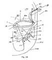
- Fig. 1Cit is shown how the normal geometry of the heart can be re-established when a system 1 according to an embodiment of a second aspect of the invention (to described in further detail below) is positioned in the heart 100.
- the systemcomprises an annuloplasty ring 210 and a tension and anchoring system 220, which allows adjustment of a set of tension members of the anchoring system 220 from the exterior side of the heart wall on the beating heart, such that an improved correction of the geometry of the heart 100 can be accomplished.
- Fig. 2Arepresents in a simplified diagram form, an embodiment of a first aspect of a surgical system 1 for altering the geometry of the heart 100, in the form of a system 1 adapted to restoring the normal geometry of the mitral valve 130 subvalvular apparatus 140, 141, 170 and the geometry of the left ventricle 110.
- the system 1allows adjustment of tension member through the atrium 150 of the heart.
- the system 1according to the embodiment of the invention shown in Fig 2A includes a complete, substantially rigid, hollow mitral annuloplasty ring 10 and a tension and anchoring system 20 adapted to align the papillary muscles 170 with the annulus 180 and to align the wall of the left ventricle with respect to the mitral valve 130 in order to eliminate ischemic/functional mitral regurgitation 136 (see explanation above).
- the tension systemcomprises a set of tension members 21, 22, 23, 24, e.g. in the form of strings or sutures.
- Each of the tension memberscomprises a first end 21a, 22a, 23a, 24a and a second end 21b, 22b, 23b, 24b, respectively.
- Said first ends 21a, 22a, 23a, 24aare intended to be led to a position at the exterior of the heart for adjustment of a set of anatomical lengths/distances defining the geometry of the ventricle 110 of the heart 100.
- Said second ends 21b, 22b, 23b, 24bare intended for fixture to a position on or through the papillary muscles 170.
- the annuloplasty ring 10is hollow forming at least one circumferential channel 14 to allow passage of a potion of a set of the tension members 21, 22, 23, 24 (as indicated by the dotted line in the ring 10 shown in Fig. 2A ) that constitute part of the tension system 20.
- the annuloplasty ring 10is attachable to the annulus 180 of the heart 100. Its rigidity will - when attached to the annulus - support the geometry of the annulus 180.
- the tension members 21, 22, 23, 24may run in a single or in multiple separate internal compartments or circumferential channels formed along portions of the perimeter of the annuloplasty ring 10. One end 21a, 22a, 23a, 24a of each tension member extending from one side (the upper side 10a) and another end 21b, 22b, 23b, 24b extending from the opposite side (the lower side 10b) of the annuloplasty ring 10.
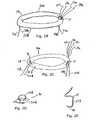
- These compartment(s)communicate with an upper (atrial) side 10a of the ring via a single aperture 11 in the annuloplasty ring 10 as shown in Fig. 2B , through which aperture the first ends 21a, 22a, 23a, 24a, of said tension members extend to the atrium side 10a of the annuloplasty ring 10.
- the first ends 21a, 22a, 23a, 24aare extendable to the exterior wall 151 of the atrium 150 of the heart 100 (see below), and thus must be adapted to a suitable length for this purpose.
- the singular aperture 11may in alternative embodiments be substituted with a number of individual apertures (not shown) for each tension member 21, 22, 23, 24 provided these apertures are situated close to each other on the ring, i.e. within a 30° angle of the ring 10.
- the internal compartment(s) of the ring 10also communicate with the lower (ventricular) side 10b of the ring 10 via a set of preferably two apertures 12, 13 formed in the lower surface 10b of the annuloplasty ring 10 as shown in Fig. 2C .
- the second ends 21b, 22b, 23b, 24b, of said tension membersextend to the ventricular side 10a of the annuloplasty ring 10.
- the second ends 21b, 22b, 23b, 24bare adapted to be extendable to the papillary muscle of the left ventricle (see below), and thus must be adapted to a suitable length for this purpose.
- the lower side 10b apertures 12, 13are preferably situated diametrically across from each other.
- Two tension members 21, 22extend trough one of the lower apertures 12 and two other members 23, 24 are carried through the other of the lower side apertures 13.
- the above mentioned apertures 11, 12, 13may be reinforced along the rim of the apertures 12, 12, 13 in order to increase the resistance to wear and tear of tension members being moved/drawn with respect to the apertures.
- the lower (ventricle) side 11b of the annuloplasty ring 10may be provided with one aperture for each tension member 21, 22, 23, 24.
- the system 1according to the embodiment of the first aspect of the invention shown in Fig. 2A further comprises an exterior heart wall anchor 36 attachable to said first ends 21a, 22a, 23a, 24a, of said tension members 21, 22, 23, 24, for attaching/fixing said first ends 21a, 22a, 23a, 24a, with respect to a position on the exterior dome wall 151 of the atrium 150.
- the second ends 21b, 22b, 23b, 24b, of the tension membersare attachable/fixable to the tip 170a of the papillary muscle 170, by a first set of papillary anchors 30 of the system 1.
- These papillary anchors 31, 32, 33, 34may in their simplest form be sutured fixture points for the second ends 21b, 22b, 23b, 24b of the tension members 21, 22, 23, 24.
- the anchorsmay also comprise a slap 30a and a loop 30b attached to said slap 30a on one side. On the other side the slap may be provided with means for fixing the anchor to the papillary muscle e.g. apertures for pins, sutures, hooks, screws or an ingrowth enhancing material.
- a tension membercan be anchored by providing a pad or anchor 30, e.g. in the form of a disc-shaped slap on an exterior surface of a wall 111 of the heart 100.
- a pad or anchor 30e.g. in the form of a disc-shaped slap on an exterior surface of a wall 111 of the heart 100.
- Such an anchormay be provided with a mechanism for securing the tension member in a fixed position with respect to the anchor 30.
- a mechanismmay be a loop or a hole to which a flexible tension member may be tied.
- the mechanismmay also comprise means for pinching screwing or otherwise adjustably securing the tension member in fixed position.
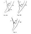
- Fig. 6Ait is shown how a tension member can be anchored by providing a pad or anchor 30, e.g. in the form of a disc-shaped slap on an exterior surface of a wall 111 of the heart 100.
- Such an anchormay be provided with a mechanism for securing the tension member in a fixed position
- FIG. 6Bit is shown how a tension member 21 can be anchored to a papillary muscle 170 tip by simple suturing.
- Fig. 6Cit is shown that the anchoring may be provided by the tension member 21 is secured to a papillary muscle 170 via a slap of flexible material which may itself be sutured onto the tissue.
- anchors 30, 31, 32, 34may be anchored to other points within the ventricle 11, apart from the papillary tips 170a , 171b, in suitable places on the ventricular wall.
- the system 1thereby provides for adjusting to a desired fixed maximum distance between each of the papillary muscles 170 and a fixed point (at the aperture 12, 13 on the lower side 10b) on the annuloplasty ring 10, and thereby on the annulus (When the annuloplasty ring 10 is attached to the annulus 180.
- the geometry of the left ventriclecan be altered, i.e. restored partly or fully to its normal geometry, using the device according to the above described embodiments of the first aspect of the invention, in a way described below.
- the system 1 according to this embodiment of the inventionis generally similar to the one described above, and with the same variation possibilities.
- the system 1 in this embodimentfurther comprises an additional tension member, namely an inter-papillary tension member 25 formed attachable by a second end 25b to one of one papillary muscle tip 170a via a fist inter-papillary anchor 31, and an additional second inter-papillary anchor 32.
- the system 1is formed with the interpapillary tension member 25 extending through said annuloplasty ring 10.
- a first end 25 of said inter-papillary tension member 25preferably extends through said aperture 11, together with tension members 21, 22, 23 and 24 as shown in the figure ( Fig. 3 ). However, it may also extend through a separate aperture (not shown), provided that the aperture is located within the same angle as specified for the tension members 21-24 in the Fig. 2 -embodiment described above.
- the second end 25b of said inter-papillary tension member 25preferably extends through the other, lower side 10b of the annuloplasty ring 10, through one of said lower side apertures 12, 13.
- a separate aperturemay be provided for the inter-papillary tension member 25 on the lower side 10b of the annuloplasty ring 10.
- the second end 25b of said inter-papillary tension member 25is adapted such that the length at least allows an extension of the member 25 from the ring 10 to a first papillary muscle tip 170 and on to the other papillary muscle tip 170a.
- the geometry of the left ventriclecan be altered, i.e. partly or entirely restored to its normal geometry, using the device according to the above describe embodiments of the first aspect of the invention, in a way described below.
- the interpapillary distancemay be very easily adjusted.
- the system 201comprises an annuloplasty ring 210, a set of tension members 220, 221, 222, 223, 224 and a first set of papillary anchors 230 for connecting each said annulus-papillary tension members 221, 222, 223, 224 to either of a set of papillary muscle 170, 171 of a heart 100, or alternatively to other positions on the ventricular wall.
- the annuloplasty ring 210is attachable to an annulus 180 of the heart 100. It has an upper side 210a and a lower side 210b which when the ring 210 is inserted in the heart 100 is intended to face the atrium 150 and the ventricle 110, respectively.
- the set of elongate annulus-papillary tension members 221, 222, 223, 224are each adapted for forming a link between said annuloplasty ring 210 and a papillary muscle 170, 171 of the heart 100.
- Each of said tension members 221, 222, 223, 224has a first end 221a, 222a, 223a, 224a and a second end 2221b, 222b, 223b, 224b.
- Said first ends 221a, 222a, 223a, 224aare attached fixedly to the annuloplasty ring 210, preferably such that a set of two tension members 221, 222 extend from a first point on the lower side 210b of the annuloplasty ring 210, and another set of two tension members 223, 224 extend from a second point, preferably diametrically opposed to said first point, on said annuloplasty ring 210.
- the tension membersmay alternatively extend from distinct individual points on the lower side 210b of the annuloplasty ring 210.
- Each of the annulus-papillary tension members 221, 222, 223, 224are configured such as to allow extension of said second ends 221b, 222b, 223b, 224b through a papillary muscle 170, 171 to an exterior side 170b of an exterior wall 111 of a ventricle 110 of a heart 100, to a first set of papillary anchors 230 for connecting each of the first ends 221b, 222b, 223b, 224b of said annulus-papillary tension members 221, 222, 223, 224 to said papillary muscle 170, 171.
- some or all the tension member 221, 222, 223, 224 second ends 221b, 222b, 223b, 224bmay be extended to and through other points on the ventricular wall 111, to be anchored at these points.
- the system 201may be configured such that there is one anchor 230 available for each papillary muscle 170, 171, such that a first set of two tension members 221, 223 can be attached to and adjusted at one anchor 231 and second set of tension member can be attached to a second anchor 232.
- the system 201may further comprise tubular members 300 for providing a channel through the papillary muscle 70, 71 or the ventricular wall 110, the tubular members being adapted for guiding the tension members 221, 222, 223, 224.
- the tubular membersmay be formed integrally with anchors 230.
- the anchors 230have means for individually fixing each of the second ends 221b, 222b, 223b, 224b of said annulus-papillary tension members 221, 222, 223, 224, such that the length of each tension member can be adjusted Individually.
- the geometry of the left ventriclecan be altered, i.e. partly or entirely restored to its normal geometry, using the device according to the above describe embodiments of the second aspect of the invention, in a way described below.
- the system 201 according to this embodiment of the inventionis generally similar to the one described above (with reference to Fig. 4 ), and with the same variation possibilities as described for that embodiment.
- the system 201 in the present embodimentfurther comprises an additional tension member, namely an inter-papillary tension member 225 for forming a link between the two papillary muscles 170, 171, adjustable from a position exterior to the ventricle wall, upon insertion of the system into the heart 100.
- the inter-papillary tension member 225has a first end 225a and a second end 225b.
- the system 201further comprises a third papillary anchor 237 for fixing the first end 225a of said interpapillary tension member 225 to a papillary muscle 171, and fourth papillary anchor 238 through which the second end 225b of said inter-papillary tension member 225 is extendable, the inter-papillary tension member 225 being configured such that the second end 225b can be extended to the exterior side of said ventricle wall 111 to be secured to one of the first set of anchors 30 of the system 1, through a papillary muscle 170 of said heart 100, and in such a way that the distance of the inter-papillary link between the papillary muscles 170, 171 is adjustable from a position exterior to the heart 100.
- the system 1is configured such that second end 225b of the interpapillary tension member 225 is fixable to one anchor of said first set of anchors 230, and such that this anchor 230 has means for individually fixing the second end 225b of said inter-papillary tension member 225.
- the geometry of the left ventriclecan be altered, i.e. partly or entirely restored to its normal geometry, using the device according to the above describe embodiments of the first aspect of the invention, in a way described below.
- the interpapillary distancemay be very easily adjusted.
- the annuloplasty ring 10, 210is in either aspect of the invention preferably formed from a biocompatible material.
- Suitable biocompatible materialsare known in the medical industry, and include DacronTM, titanium, silicone, nitinol, polyesters, and denatured biological material.
- the tension members 21, 22, 23, 24, 25, 221, 222, 223, 224, 225 in either aspect of the invention,are preferably formed in a biocompatible material.
- Suitable biocompatible materials known from the medical industryinclude DacronTM, titanium, silicone, nylons, polypropylene, nitinol, polyesters, and denatured biological material.
- the mitral valve 130is exposed using standard surgical techniques, by resecting the heart wall 151 at the atrium 150, and inserting the system 1 according to either of the aspects as outlined above. This initial step of course is common to all aspects of the methods as described below.
- the second ends 21b, 22b, 23b, 24b of the valve/papillary tension members 21, 22, 23, 24are brought from the atrial 180a, to the ventricular 180b aspect of the annulus 180 by piercing the annulus 180 at positions corresponding to the points of exit of the tension members 21, 22, 23, 24, from the annuloplasty ring 10.
- This piercingmay be provided by a separate surgical tool, or it may be provided by needles/suture needles (26) disposed at the second end of one or more of said tension members, see Fig.
- the second ends 21b, 22b, 23b, 24bare secured/fixated to the papillary muscle tips 170a (or a place on the ventricular wall 111) by means of suitable anchors 30 of the system 1 or other fixation means.
- the annulus-papillary tension members 21, 22, 23, 24are distributed such that a tension member from each point of exit on the annuloplasty ring 10 is connected to each papillary muscle tip 170a.
- the annuloplasty ring 10is fixated to the atrium side 180a of the annulus 180 e.g. by means of interrupted sutures following standard surgical techniques.
- the second ends 21b, 22b, 23b, 24b of the annulus- papillary tension members 21, 22, 23, 24 to the tips 170a of the papillary muscles 170they may be passed through the papillary muscles 170 and the left ventricular wall to the epicardial aspect 170b of the papillary muscle base and fixated to an anchor exterior to the heart wall at this position (not shown).
- a further inter-papillary tension member 25may be placed in the heart along with the valve-papillary tension members 21, 22, 23, 24.
- a second end 25b of the inter-papillary tension member 25is brought through the annulus 150 together with the second ends 21b, 22b, 23b, 24b of valve-papillary tension members 21, 22, 23, 24.
- An inter-papillary anchor 45is then fixed to a tip 170a of one of the papillary muscles 170.
- the ventricular end 25b of the inter-papillary tension member 25is then connected via the inter-papillary anchor 32 to the tip 170a of the other papillary muscle 170, where it is fixated, by means of suitable anchors or other fixation means. Then the first end of the inter-papillary tension member 25 is exteriorized through the dome 151 of the left atrium 150 together with the first ends 21a, 22a, 23a, 24a of the valve-papillary tension members 21, 22, 23, 24, and adjusted (tightened or loosened relative to each other) to maximize cardiac function and valve competence.
- tension members 21, 22, 23, 24, 25are tied in a standard surgical fashion, or tightened in a standard surgical fashion around an anchor 35 such as a special epicardial pad to reduce the local myocardial damage on the exterior side of the atrial dome 151. Thereby restoration of the normal continuity between the papillary muscles 170 and left ventricular wall and the mitral valve 130 may by accomplished.
- the annuloplasty ring 10may alternatively be entered through the mitral valve 130 from the atrium 150 to the ventricular cavity 110 and secured/fixated to the ventricular side 180b of the annulus 180 upon securing the second ends 21b, 22b, 23b, 24, 25b at their respective locations as described above. Consequently, the first ends 21a, 22a, 23a, 24a, 25a of the tension members must be brought through the annulus 180 prior to fixating the annuloplasty ring to the annulus.
- the first ends 21a, 22a, 23a, 24a, 25a of the tension membersare then exteriorized through the dome 151 of the left atrium 150, adjusted and tied or tightened and anchored in a standard surgical fashion on the exterior side of the atrial dome 151, in the same manner as described above.
- the first ends 221a, 222a, 223a, 224a of the annulus-papillary tension members 221, 222, 223, 224are brought from the atrial 180a to the ventricular 180b aspect of the annulus 180 by piercing the annulus 180 at positions corresponding to the points of departure of the tension members 221, 222, 223, 224 from the annuloplasty ring 210.
- the annuloplasty ring 210is fixated to the atrium side 180a of the annulus 180, e.g. by means of interrupted sutures following standard surgical techniques.
- the first ends 221a, 222a, 223a, 224a of the annulus-papillary tension members 221, 222, 223, 224are passed through the papillary muscles 170 and left ventricular wall 111 from the papillary muscle tips 170a to the epicardial aspect 170b of the papillary muscle base, such that the first ends 221a, 222a, 223a, 224a are exteriorized at the epicardial aspect 170b of the papillary muscle bases (as a rule at two locations).
- the annulus-papillary tension members 221, 222, 223, 224may be passed through a passage pierced through the papillary muscle 170, either from the ventricular side 170a of the papillary muscles 170, or from the epicardial aspect 170b of the papillary muscle bases on the exterior side of the ventricular wall 111.
- this passagemay be equipped with a tubular anchor extending through the papillary muscle 170 forming an enforced channel.
- valve-papillary tension members 221, 222, 223, 224are distributed such that each of a pair of tension members from each point of departure on the annuloplasty ring 210 are connected to different ones of the papillary muscle tips 170a.
- At least one passage for each tension memberis preferably formed through each papillary muscle 170, through which the tension member is passed.
- all the tension members through a papillary muscle 170may be passed through a single passage formed in each papillary muscle 170.
- the heartis surgically closed, its cavities evacuated from air and allowed to fill with blood, and normal heart rhythm resumed.
- the tension members 221, 222, 223, 224are adjusted (tightened or loosened relative to each other) to maximize cardiac function and valve competence.
- the tension members 221, 222, 223, 224are tied in a standard surgical fashion, or tightened in a standard surgical fashion around an anchor such as a special epicardial pad to reduce the local myocardial damage.
- a further inter-papillary tension member 225may be placed in the heart along with the valve-papillary tension members 221, 222, 223, 224.
- a ventricular end 225b of the inter-papillary tension member 225is fixed to a tip 170a of one of the papillary muscles 170, either at a separate fixture or to a ventricle end of one tubular papillary anchor.
- An inter-papillary anchor 32is then fixed to a tip 170a of the other of the two papillary muscles 170 in connection with a passage pierced through the papillary muscle 170, either from the ventricular side 170a of the papillary muscles 170, or from the epicardial aspect 170b of the papillary muscle base on the exterior side of the ventricular wall. Then the first end 225a of the inter-papillary tension member 25 is exteriorized via the inter-papillary anchor 32 through the passage.
- the annulus-papillary tension members 21, 22, 23, 24are then adjusted by manipulating the second ends 221b, 222b, 223b, 224b of the valve-papillary tension members 221, 222, 23, 224, (tightened or loosened relative to each other) to maximize cardiac function and valve competence.
- the tension members 221, 222, 223, 224, 225tightened in a standard surgical fashion around an anchor 230 such as a special epicardial pad to reduce the local myocardial damage on the exterior side of the epicardial aspect 170b of the papillary muscle base.
- the annuloplasty ring 10may alternatively be entered through the mitral valve 130 from the atrium 150 to the ventricular cavity 110 and secured/fixated to the ventricular side 180b of the annulus 180, and the remainder of the method can be carried out as outlined above.
- Similar methodsmay apply for the right atrium/ventricle and tricuspid valve, by adapting the system and methods to forming links between each of the three papillary muscles (corresponding to the three leaflets of the tricuspid valve) in the right ventricular chamber.
- the tension membersmay be marked (texture) or colour-coded texture in order to differentiate between the tension members, and thereby between the relevant anatomical lengths inside the beating heart to be adjusted. Markings/attachable signs could also be attached to the first ends 21a, 22a, 23a, 24a, 25a, during the surgical procedure as each tension member is exteriorized in order to differentiate between the tension members/anatomical lengths when the adjustment step is to take place.
- the annuloplasty ring 10may be provided with a an extension tubing 60 communicating with the internal compartment 14 of the ring 10 through the aperture 11 in upper side 10a of the ring 10.
- the extension tubing 60is adapted to extend through the atrium 150 and through the atrium wall 151, and carries the first ends 21a-24a (or 25a) of said tension members 21-24 (or 25).
- the extension tubing 60is provided with means disposed at the end 61 closest to the annuloplasty ring 10 for squeezing of and fixating the tension members by turning of the extension tubing 60 around the longitudinal axis thereof.
- the tension member lengthcan be adjusted from the external side of the atrium on the beating heart by turning an externally extended part 62 of the extension tubing 60, thus securing the tension members in the correct position.
- a cutting mechanisme.g. by an internal flange having a cutting edge, activated by further squeezing of and cutting the tension members, said cutting edge being disposed above said fixation point in said extension tubing 60, and being actuated by a further turning action of the extension tubing 60; and by means for cutting off at least a section of the extension tubing 60 itself (e.g.
- a major part of the extension tubing 60can be pulled out of the atrium 150, leaving the tension members anchored at the annuloplasty ring 10 inside the atrium.
- a restoration of the geometry of the heartcan be accomplished from the atrium side, leaving no anchors on the atrium wall, which is thinner than e.g. the ventricle wall.
- the atrium wallcan be further relieved of some stress over the long term.
- the annuloplasty ring 10may be provided with an alternative system 40 for fixating said tension members 21-24 (or 25) at said atrium/upper side 10a of said annuloplasty ring 10.
- the annuloplasty ring 10is provided with a short upwardly directed tubular extension 41, communicating with the upper aperture 11.
- the tension membersare extending through said tubular extension 41.
- a pin 45 having a threadingis provided in the tubular extension 41 .
- the threadingis adapted for cooperation with an internal threading of a plugging member 43 adapted to be received in said tubular extension 41.
- the tubular extensionfurther has a cutting edge 42.
- the Plugfurther has a conical outer surface for cooperation with said edge 42, and preferably a corresponding conical part in the upper part of the tubular extension 41 lumen.
- the annuloplasty ring 10may be provided with an alternative system 40 for fixating said tension members 21-24 (and 25) at said atrium/upper side 10a of said annuloplasty ring 10.
- the annuloplasty ring 10has a tension member hub 310 through which the tension members 21-25 are extended, the hub 310 providing means for fixating the tension members 21-25 when the desired length/tension has been achieved.
- the annuloplasty ring 10may have a saddle shape with a hub 310 at one side.
- the shape of the annuloplasty ring 10is adapted to the natural shape of the annulus 180.
- annuloplasty ring 10may in other embodiments be e.g. circular or oval- shaped, or have other 3-dimentional configurations in order to adapt the annuloplasty ring to aid the restoration7repair of the individual annulus and mitral valve dilation.
- the annuloplasty ring 10comprises a set of additional, attachment holes 320, extending through the ring 10 from the atrium, upper side 10a to the lower, ventricle side 10b.
- additional attachment holes 320are provided as a means of sewing/stitching/suturing the ring 10 to the annulus 180 of the heart.
- other means for attachment/fixating the annuloplasty ring 10 to the annulusmay be provided as alternative or as additional to the attachment holes 320.
- the annuloplasty ring 10may e.g. be provided with a web of material on the outer surface of the ring 10, as known in the art, providing an anchoring for the suturing the ring 10 to the annulus.
- the hub 310 of the annuloplasty ring 10comprises a through hole 311 in which a locking part 330 for locking/fixating the tension members 21-25 is mountable, the locking part 330 also having a through hole 331.
- the hub 310further comprises fastening means 340, 350 for locking/fixating the locking member to the though hole 311 of the hub 310.
- the fastening member 340may be tightened by a specially adapted hollow tightening tool 400.
- the fastening means 340, 350are a bolt 340 (having a through hole 341) an nut 350 (having a through hole 351), and the tightening tool 400 have an Allen key type means 445 of engaging the fastening means (the bolt 340), the fastening means 340 having cooperating engagement means 345.
- the nut 350may be replaced by a treading provided within at least a section of the hub 310 through hole 311.
- the fastening part 340(the bolt) extends through the through hole 331 in the locking part 330 and the through hole 311 in the hub 310.
- the fastening part 340has a threading cooperating wit a threading on the lower fastening part 350 (the nut).
- the lower fastening part 350is received in and prevented from rotation with respect to the hub 310.
- the locking member 330is received in the through hole 311 of hub 310 such that is prevented from rotation, preferably by corresponding parts of the locking part 320 and the through hole 311 being non circular.
- the annuloplasty ring 10has a set of apertures 11 provided in the upper/atrium side 10a, for accommodating the tension members 21-25 extending from the atrium of the heart.
- the apertures 11 on the upper side 10acommunicate with a set of apertures 12, 13 on the lower (ventricle) side 10b of the annuloplasty ring 10, from/to where a set of tension members 21-25 can be extended to be fixed to regions of the ventricle of a heart (when inserted into the heart of a human or animal).
- all the apertures 11 on the upper side 10aare located at the hub 310 in order to provide an easy way of adjusting and fixating the tension members from a position outside the heart and through the atrium.
- Some of the communicating apertures 11, 13are communicating via channels 313 through the annuloplasty ring 10 that are located in the vicinity of the hub 310, such that the lower side 10b apertures 13 are located on or right next to the lower side of the hub 310.
- Other of the communicating apertures 11, 12are communicating via channels 312 through the annuloplasty ring 10 that extend from the upper side 10a apertures 11 to the lower side 10b apertures on positions arranged distributed over the lower surface 10b of the ring 10.
- these lower side 10b apertures 12are preferably located at positions diametrically opposite the hub 310 in order to provide an optimal distribution of the tension members 21-25, to allow the best possible adjustment to restore or improve the geometry of the ventricle.
- the channel(s) 312 extending from the upper apertures 11 at the hub to the diametrically opposed lower side 10b apertures 12may extend completely within the annuloplasty ring 10 as closed channels. However, in other embodiments, at least part of the channel(s) 312 may be provided as open grooves (e.g. c-shaped in cross section) in the outer perimeter of the annuloplasty ring 10. A (partly) open channel may allow for easier placement/mounting of the tension members 21-25 at manufacture or on site prior to the insertion of the annuloplasty ring/system for altering the geometry of the heart.
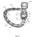
- a (partly) open channel 312is illustrated in fig. 16 , which shows a sectional view through an annuloplasty ring 10, the locking part 330, the fastening parts 340,350 (bolt and nut) being screwed into the ring 10, and a tension member 21-25 being shown to indicate how the tension members are carried for fixation.
- Fig. 16the space between the individual components has been exaggerated in order to allow illustration of the path of a tension member 21-25 through the annuloplasty ring 10.
- the channel 312begins at the aperture 11 and extends through the hub 310 to the outer perimeter of the ring 10 proper as a closed channel, then around the outermost part of the ring perimeter as an open channel.
- the channels 312may in other embodiments be closed through its entirety from upper apertures 11 to lower apertures 12.
- Figure 16also illustrates the path of a tension member 21-25 through the annuloplasty ring 10, as could be the situation when the ring 10 is fixed to the annulus, the tension members 21-25 being adjusted and fixed.
- the tension member 21-25extends from the atrium side (up in the figure) down through a through hole 341 in the fastening member 340. Then the tension member 21-25 extends back up between the outer surface of the fastening member 340 and surface of the through hole 311 of the hub 310 and on between a flange 314 of the through hole 311 of the hub 310 and a lower surface 334 of the locking part 330.
- the tension memberenters the hub 310 of the ring 10 through upper aperture 11 in the ring 10.
- the tension memberis the shown extending through a channel 313 in the vicinity of the hub 310 to aperture 13 and through the tissue surrounding the annulus and into the ventricle.
- Another tension member 21-25(not shown in Fig. 16 ) would extend into channel 312 to extend to a position opposite the hub 310 or on another location on the circle of the annuloplasty ring lower side 10b.
- the tension memberis fixated in the desired position by screwing the upper fastening part 340 (the bolt) in such that the tension member is locked or squeezed between the surfaces 314, 334 on the hub 310 and locking part 330, respectively.
- the tension memberis rotated and/or ruptured during the screwing in of the fastening member.
- a set of groves 360is provided on the lower side of the hub 310.
- a set of grooves 356are provided on the lower surface of the lower fastening part 350.
- the annuloplasty ring 10is inserted into the heart through the atrium, as is the case with the other embodiments and aspects described above.
- the annuloplasty ring 10is fixed to the annulus by means of suturing the ring 10 via the attachment holes 320 (or by any of the other means described), as is the case with the other embodiments and aspects described above.
- the pre-installed tension members 21-25are, or have been, extended into the ventricle through the tissue of the annulus and secured to the respective desired points in the ventricle (papillary muscles or other points on the inner ventricle wall), or they may be anchored through the papillary muscles, as described above.
- the opening through the atrium wall through which the annuloplasty ring/system was enteredis then partly closed, the tension members passed through the remaining opening.
- the heartis weaned from cardiopulmonary bypass, such that it is beating.
- the tension membersare adjusted such that the original geometry of the heart (or at least the ventricle) is obtained, or at least partly regained.
- the tension membersare locked or fixated in the desired position (state of tension) obtained by the adjustment by turning of the fastening member 340 by a tightening tool 400 engaging the fastening member 340.
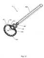
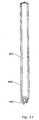
- the tightening tool 400is hollow, i.e. it has an elongate bore 401, extending through the length of the tool 400, as can be appreciated from Fig. 17 , showing an elongate section through the tool 400.
- the tension members 21-25can be contained within the bore 401 when the locking occurs (by turning of the tightening tool 400 engaging the upper fastening part 340 (the bolt)), and when the adjustment of the tension member lengths in the ventricle takes place.
- the part of the tension members situated in the atriummay be cut at the ring 10, the tightening tool 400 is retracted and the remaining opening in the atrium wall is closed. Otherwise the tension members 21-25 may be left extending from the ring 10 to the opening in the atrium, the tightening tool 400 is retracted and the remaining opening in the atrium wall is closed, and the tension members secured to the outer wall of the atrium.
- the atrium end of the tension membersare preferably passed through the elongate bore or cavity in the tightening tool entered through the opening in the atrium, such that the adjustment of and the tightening/locking of the tension members can be carried out using the tightening tool.
- the tightening tooltherefore is adapted in length to be able to reach to the annulus of a heart from the outside of the atrium of a heart.
- the opening in the atriummust be partly closed, in order to allow access to the annuloplasty ring (with the tightening toll) an at the same time prevent blood flow from the opening. This is preferably done by providing the opening with a purse string suture.
- a scanninge.g. an MR scanning of the heart may be performed in order to prepare the procedure and possibly make adjustments to the system in general or the annuloplasty ring in particular.
Landscapes
- Health & Medical Sciences (AREA)
- Cardiology (AREA)
- Life Sciences & Earth Sciences (AREA)
- General Health & Medical Sciences (AREA)
- Public Health (AREA)
- Biomedical Technology (AREA)
- Heart & Thoracic Surgery (AREA)
- Engineering & Computer Science (AREA)
- Animal Behavior & Ethology (AREA)
- Veterinary Medicine (AREA)
- Surgery (AREA)
- Transplantation (AREA)
- Oral & Maxillofacial Surgery (AREA)
- Vascular Medicine (AREA)
- Nuclear Medicine, Radiotherapy & Molecular Imaging (AREA)
- Medical Informatics (AREA)
- Molecular Biology (AREA)
- Rheumatology (AREA)
- Prostheses (AREA)
- Electrotherapy Devices (AREA)
- Surgical Instruments (AREA)
Abstract
Description
- The present invention concerns a system for altering the geometry of a heart while the heart is beating.
- pas de Par suite du par précédent More specifically the invention concerns a system comprising a number of tension members adapted for restoring the internal geometry of ischemically or otherwise damaged heart chambers. The system can furthermore be used to alleviate ischemic or functional mitral regurgitation.
- Despite advances in pharmacologic and interventional therapy, development of functional ischemic mitral regurgitation (MR) after myocardial infarction remains a fundamental cause of morbidity and mortality, especially in western societies. In the United States approximately two million patients suffer from functional ischemic MR, and the annual number of deaths related to this clinical manifestation of ischemic heart disease is increasing. The underlying mechanism for this condition is primarily a dilatation of the left ventricular chamber, which leads to displacement of the papillary muscles. Displacement of these cardiac muscular prominences hamper correct closure of the mitral valve during the ventricular systole and therefore the valve becomes insufficient.
- Standard surgical therapy for functional ischemic MR at the time of coronary revascularization (coronary bypass surgery) involves the implantation of a mitral annuloplasty ring, designed to restore coaptation by correcting the posterior annular dilatation common in these patients. Although this can be effective in some patients, results have been variable, and persistent or recurrent MR due to progressive ventricular dilatation and papillary muscle displacement has been reported In at least 20% of the patients.
- In order to restore the original left ventricular configuration several attempts to restore left ventricular shape and function have been exhibited in form of "Coapsys" device, Dor procedure and Acorn device. However, these principles of treatment are fairly primitive or crude, and therefore do not match the complex anatomy, physiology and mechanics related to the functionality of the mitral valve. Also known in the art are a number of devices for altering the geometry of the heart, e.g. as disclosed in
WO 2005/082278 , describing a semi-circular papillary muscle and annulus bands for modifying the alignment of papillary muscles, a mitral valve annulus and/or a tricuspid valve annulus. Also disclosed are methods to effect the alignment and a sizing device that can be used for such alignment. - The set of devices disclosed In
WO 2005/082278 allows the surgeon to alter, i.e. restore the geometry of the heart. However, all of the above mentioned procedures - Including the one disclosed inWO 2005/082278 - require that the heart is stopped during the Insertion and adjustment of the devices. In this condition the geometry of the heart Is very dissimilar to that of the functioning heart since it collapses upon evacuation of blood from Its chambers. The adjustment of the functional constituents of the devices - the tension members - during heart arrest may therefore be Inaccurate, and the geometry of the device and the heart cannot be altered once the heart Is surgically closed, and cardiac function is resumed after the insertion of the device. Therefore, it is difficult to asses if the desired geometry is restored at this stage - before the heart function is resumed. US 2003/083742 discloses a valve repair apparatus and methods for ensuring proper coaptation and operation of the leaflets of a heart valve. The main aspects of the disclosure relate to devices including a support member configured for attachment to the heart valve annulus, a post extending from the support member away from the plane of the annulus and a connector coupled with the post and configured for attachment to at least one of the leaflets. The various embodiments may include a replacement heart valve connected with the support member for facilitating full replacement as opposed to near repair of an existing native heart valve. Various other devices include support structure and one or more posts connected to opposite sides of the support structure and extending from one side of the valve annulus to another to modify the shape of the annulus.WO 99/30647 - Consequently, the lengths of the devices must be very thoroughly assessed prior to the surgery procedure. Since the heart with its valves and subvalvular apparatus Is a complex dynamic system, where the individual components move in an interdependent and coordinated manner, such an assessment may be extremely difficult. Alternatively, a certain margin of error must be accepted.
- There is thus a need for a system and a method for altering the geometry of a heart that allows the altering or at least an adjustment of the geometry of the heart to take place when the heart is beating.
- It is an object of the present Invention to provide a system for altering the geometry of the heart that exerts a more advanced approach to treating ischemic mitral valve disease.
- It is a further an object of the invention to provide a system for altering the geometry of the heart, which both enables reduction and stabilization of the mitral annulus and entail remodeling of the left or right ventricle.
- It is a further an object of the invention to provide a system for altering the geometry of the heart, which allows repositioning of the papillary muscles and at the same time supports the left ventricular myocardium and prevents further dilatation of the left heart chambers.
- It Is a further object of the invention to provide a system for altering the geometry of the heart, which allows for easy insertion into and placement in the heart.
- It is a further object of the invention to provide a system for altering the geometry of the heart, which allows adjustment of the system and thereby the geometry of the heart on the beating heart.
- It is a further object of the invention to provide a system for altering the geometry of the heart, which constitutes an alternative to existing devices for altering the geometry of the heart.
- The object of the invention is accomplished by a first aspect of a system for altering the geometry of a heart while the heart is beating comprising an annuloplasty ring for altering geometry of an annulus of the heart, being attachable to said annulus, and having an upper side and a lower side; a set of elongate annulus-papillary tension members each of which tension members are adapted for forming a link between said annuloplasty ring and a papillary muscle of the heart, each of said tension members having a first end and a second end; and a first set of papillary anchors for connecting each of the second ends of said annuluspapillary tension members to said papillary muscle; characterized in that said annuloplasty ring has at least two apertures located on said lower side and one aperture located on said upper side and where each of said annulus-papillary tension members are extendable through said annuloplasty ring through said apertures, and through an atrium of said heart to an exterior side of an exterior wall of said atrium, such that the distance of each link between the annulus and the papillary muscles is adjustable from a position exterior to the heart, and characterized in that at least one circumferential channel is formed inside the annuloplasty ring, said channel communicating with said aperture on the upper side and with the at least two apertures on the lower side of said annuloplasty ring, such that said tension members are extendable through said apertures on the lower side through said channel and through said aperture on the upper side.
- Thereby is achieved a system in which the normal geometry of the ventricle can be re-established from the exterior of the heart at the exterior atrium wall. This allows a surgeon to perform the adjustment process of the tension members of the system, not only on the beating heart, but also on the beating heart that is correctly positioned In the thorax. This is due to the orientation of the left atrium in the body of a human. The left atrium is ready accessible when the thorax has been opened.
- In an embodiment of the first aspect the system further comprises an inter-papillary tension member for forming a link between said papillary muscles, said inter-papillary tension member having a first end and a second end; a first inter-papillary anchor for fixing the second end of said interpapillary tension member to a papillary muscle; and a second Inter-papillary anchor through which the first end of said inter-papillary tension member is extendable, said inter-papillary tension member further being extendable through a ventricle of said heart, and through said annuloplasty ring via said apertures and through an atrium of said heart to an exterior side of an exterior wall of said atrium, such that the distance of the inter-papillary link between the papillary muscles is adjustable from a position exterior to the heart.
- Thus the distance between the papillary muscles can also be adjusted from the exterior atrium side on the beating heart.
- In a further aspect of the invention the object is achieved by a system as stated in
claim 12 and sub claims 13-16. - More particularly a system for altering the geometry of the heart is achieved in which the ventricle geometry may be adjusted on a beating heart, from a position outside the heart, and through the ventricle.
- The object of the invention may further be achieved by an annuloplasty ring for altering the geometry of an annulus of the heart while the heart is beating, being attachable to said annulus, and having an upper side and a lower side, characterized in that said annuloplasty ring has at least two apertures located on said lower side and one aperture located on said upper side and wherein a set of tension members are extendable through said annuloplasty ring through said apertures, and characterized in that at least one circumferential channel is formed inside the annuloplasty ring, said channel communicating with said aperture on the upper side and with the at least two apertures on the lower side of said annuloplasty ring, such that said tension members are extendable through said apertures on the lower side through said channel and through said aperture on the upper side.
- Such an annuloplasty ring may be used with any of the embodiments of the first aspect of the invention as cited above.
- The annuloplasty ring may further comprise a channel formed along the circumference of the annuloplasty ring, said channel connecting said upper aperture located on said upper side to at least one aperture located on said lower side, where the upper and lower apertures are positioned diametrically across from each other on the circumference of the annuloplasty ring.
- The annuloplasty ring may further comprise a tension member hub having a set of upper apertures communicating with a set of lower apertures via a set of channels, and where a set of tension members may be locked to the annuloplasty ring at said hub.
- The annuloplasty ring hub may comprise a locking part mounted in a through hole of the hub for locking/fixating tension members, and fastening means for locking/fixating the locking part to the though hole of the hub.
- The invention further regards a system according to the first aspect of the invention that further comprises a tightening tool for fasting the fastening member in order for locking/fixating tension members.
- In the following the invention is described in further detail with reference to the drawings in which
Figs. 1A-C , in schematic form, show a section through a portion of a heart, in three conditions;Fig. 2A shows, in schematic form, a perspective view of a system for altering the geometry of a heart according to a first aspect of the invention, when situated in a heart;Figs. 2B-E shows, in schematic form, a perspective view of components of the system shown infig 2A ;Fig. 3 shows, in schematic form, a perspective view of the system for altering the geometry of a heart according to an embodiment of the first aspect of the invention, when situated in a heart;Fig. 4 shows, in schematic form, a perspective view of a system for altering the geometry of a heart according to a second aspect of the invention, when situated in a heart;Fig. 5 shows, in schematic form, a perspective view of a system for altering the geometry of a heart according to an embodiment of the latter (second) aspect of the invention, when situated in a heart;Figs. 6A-C shows different option for anchoring tension member to a papillary muscle;Fig. 7A shows a perspective view of a system for altering the geometry of a heart according to an embodiment of the first aspect of the invention;Fig. 7B shows a top view of the system shown inFig. 7A ;Figs. 8A-D shows details of yet another embodiment of a system for altering the geometry of a heart according to the first aspect of the invention.Fig. 9 , in an exploded, perspective view, shows details of yet another embodiment of a system, including a tightening tool, for altering the geometry of a heart according to the first aspect of the invention; the system is shown from the lower side;Fig. 10 , in another exploded, perspective view, shows the system ofFig. 9 ; the system is seen from above;Fig. 11 , shows an outline of the system inFig. 10 ;Fig. 12 , in a perspective view, shows the system ofFigs. 9-11 in an assembled state, and with a tightening tool engaging an annuloplasty ring of the system;Fig. 13 , in an exploded perspective view, shows details of an annuloplasty ring for a system as shown inFigs. 9-13 , as seen from above;Fig. 14 shows an outline of the annuloplasty ring ofFig. 13 ;Fig. 15 , in outline, shows the annuloplasty ring ofFig. 13 , as seen from below;Fig. 16 ; shows a section through a hub part of an annuloplasty ring as shown inFigs 13-15 ; andFig. 17 shows a section through a tightening tool for tightening/locking/fastening tension members at an annuloplasty ring of a system for altering the geometry of a heart.- Initially and in order to describe the present invention, an example of a physical condition of a
heart 100 that can be remedied using the system of the present invention is briefly described with reference toFigs. 1A-C .Fig. 1A shows a section through a portion of a normally functioningheart 100. More particularly,Fig. 1A shows in schematic form a long-axis section through aleft ventricle 110 of anormal heart 100 during systole. Theaortic valve 120 is open (the arrows in the vicinity of thevalve 120 indicating the flow of blood), while themitral valve 130 is closed. Themitral valve 130 has twoleaflets 131. Primary andsecondary chordae leaflets 131 of themitral valve 130 interact over a broad, so-called coaption area 135 to ensure a tightmitral valve 130 function, thus preventing blood to re-enter the left atrium 150 (mitral regurgitation 136, seeFig. 1B ). In the figure (Fig. 1A ) also onepapillary muscle 170 is shown. Thechordae papillary muscles 170 are also referred to as the subvalvular apparatus. - In
Fig. 1B a section similar to the one shown inFig. 2A is shown, where a portion of the posterior left ventricular myocardial wall has formedscar tissue 160, e.g. following coronary atherosclerosis and thrombosis. As a consequence, thepapillary muscles 170 are displaced: down, out, and away from each other (in this view only a single papillary muscle is shown). Theleaflets 131 of themitral valve 130, thereby, are drawn down and into the ventricle via the secondary chordae 141 - a condition known as tethering. Consequently, themitral valve 130 leaks blood to theatrium 150 during systole, as indicated by thearrows 136, i.e. the phenomenon of mitral regurgitation is experienced. Further, as a consequence of this condition theleft ventricle 110 is enlarged/dilated. Thus, a geometrical analysis of this condition shows that the angle between theleaflets 131 of themitral valve 130 and thesecondary chordae 141 has diminished due to the increased distance between the affixture 141a of thesecondary chordae 141 to themitral valve leaflet 131 and the origin 141b of the secondary 141 chordae on thepapillary muscle 170. - In
Fig. 1C it is shown how the normal geometry of the heart can be re-established when asystem 1 according to an embodiment of a second aspect of the invention (to described in further detail below) is positioned in theheart 100. The system comprises anannuloplasty ring 210 and a tension andanchoring system 220, which allows adjustment of a set of tension members of theanchoring system 220 from the exterior side of the heart wall on the beating heart, such that an improved correction of the geometry of theheart 100 can be accomplished. - Here and in the following the invention is explained in relation to its use in the left side of the heart. It should, however, be mentioned that the invention applies also to similar conditions of the tricuspid valve (not shown) of the right side of the
heart 100, with an adaption to the three valvular leaflets of this valve. - In the following we will describe a set of aspects and embodiments of the invention. Throughout the following description of embodiments of the invention the same reference numbers are used for like parts, although they may vary slightly in detail.
Fig. 2A represents in a simplified diagram form, an embodiment of a first aspect of asurgical system 1 for altering the geometry of theheart 100, in the form of asystem 1 adapted to restoring the normal geometry of themitral valve 130subvalvular apparatus left ventricle 110.- The
system 1 according to the first aspect of the invention allows adjustment of tension member through theatrium 150 of the heart. - The
system 1 according to the embodiment of the invention shown inFig 2A includes a complete, substantially rigid, hollowmitral annuloplasty ring 10 and a tension and anchoringsystem 20 adapted to align thepapillary muscles 170 with theannulus 180 and to align the wall of the left ventricle with respect to themitral valve 130 in order to eliminate ischemic/functional mitral regurgitation 136 (see explanation above). - The tension system comprises a set of
tension members first end 21a, 22a, 23a, 24a and asecond end ventricle 110 of theheart 100. Said second ends 21b, 22b, 23b, 24b are intended for fixture to a position on or through thepapillary muscles 170. - The
annuloplasty ring 10 is hollow forming at least onecircumferential channel 14 to allow passage of a potion of a set of thetension members ring 10 shown inFig. 2A ) that constitute part of thetension system 20. - The
annuloplasty ring 10 is attachable to theannulus 180 of theheart 100. Its rigidity will - when attached to the annulus - support the geometry of theannulus 180. Thetension members annuloplasty ring 10. Oneend 21a, 22a, 23a, 24a of each tension member extending from one side (theupper side 10a) and anotherend lower side 10b) of theannuloplasty ring 10. - These compartment(s) communicate with an upper (atrial)
side 10a of the ring via asingle aperture 11 in theannuloplasty ring 10 as shown inFig. 2B , through which aperture the first ends 21a, 22a, 23a, 24a, of said tension members extend to theatrium side 10a of theannuloplasty ring 10. The first ends 21a, 22a, 23a, 24a are extendable to theexterior wall 151 of theatrium 150 of the heart 100 (see below), and thus must be adapted to a suitable length for this purpose. Thesingular aperture 11 may in alternative embodiments be substituted with a number of individual apertures (not shown) for eachtension member ring 10. - The internal compartment(s) of the
ring 10 also communicate with the lower (ventricular)side 10b of thering 10 via a set of preferably twoapertures lower surface 10b of theannuloplasty ring 10 as shown inFig. 2C . Through theseapertures ventricular side 10a of theannuloplasty ring 10. The second ends 21b, 22b, 23b, 24b are adapted to be extendable to the papillary muscle of the left ventricle (see below), and thus must be adapted to a suitable length for this purpose. - The
lower 12, 13 are preferably situated diametrically across from each other. Twoside 10b aperturestension members lower apertures 12 and twoother members lower side apertures 13. The above mentionedapertures apertures annuloplasty ring 10 may be provided with one aperture for eachtension member - The
system 1 according to the embodiment of the first aspect of the invention shown inFig. 2A further comprises an exterior heart wall anchor 36 attachable to said first ends 21a, 22a, 23a, 24a, of saidtension members exterior dome wall 151 of theatrium 150. - The second ends 21b, 22b, 23b, 24b, of the tension members are attachable/fixable to the tip 170a of the
papillary muscle 170, by a first set of papillary anchors 30 of thesystem 1. These papillary anchors 31, 32, 33, 34 may in their simplest form be sutured fixture points for the second ends 21b, 22b, 23b, 24b of thetension members Fig. 6 . InFig. 6A it is shown how a tension member can be anchored by providing a pad oranchor 30, e.g. in the form of a disc-shaped slap on an exterior surface of a wall 111 of theheart 100. Such an anchor may be provided with a mechanism for securing the tension member in a fixed position with respect to theanchor 30. In a simple form such a mechanism may be a loop or a hole to which a flexible tension member may be tied. However, the mechanism may also comprise means for pinching screwing or otherwise adjustably securing the tension member in fixed position. InFig. 6B it is shown how atension member 21 can be anchored to apapillary muscle 170 tip by simple suturing. In Fig. 6C it is shown that the anchoring may be provided by thetension member 21 is secured to apapillary muscle 170 via a slap of flexible material which may itself be sutured onto the tissue. These alternative anchoring options are not only alternatives useful for the first aspect of the invention as described above, but also for the aspects and embodiments described in the following. - Some or all of the
anchors ventricle 11, apart from the papillary tips 170a , 171b, in suitable places on the ventricular wall. - The
system 1 thereby provides for adjusting to a desired fixed maximum distance between each of thepapillary muscles 170 and a fixed point (at theaperture lower side 10b) on theannuloplasty ring 10, and thereby on the annulus (When theannuloplasty ring 10 is attached to theannulus 180. - Thus the geometry of the left ventricle can be altered, i.e. restored partly or fully to its normal geometry, using the device according to the above described embodiments of the first aspect of the invention, in a way described below.
- In the following, an alternative embodiment of the first aspect of the invention will be described with reference to
Fig. 3 . Thesystem 1 according to this embodiment of the invention is generally similar to the one described above, and with the same variation possibilities. However thesystem 1 in this embodiment further comprises an additional tension member, namely aninter-papillary tension member 25 formed attachable by asecond end 25b to one of one papillary muscle tip 170a via a fistinter-papillary anchor 31, and an additional secondinter-papillary anchor 32. Thesystem 1 is formed with theinterpapillary tension member 25 extending through saidannuloplasty ring 10. On theupper side 10a of said annuloplasty ring afirst end 25 of saidinter-papillary tension member 25 preferably extends through saidaperture 11, together withtension members Fig. 3 ). However, it may also extend through a separate aperture (not shown), provided that the aperture is located within the same angle as specified for the tension members 21-24 in theFig. 2 -embodiment described above. - The
second end 25b of saidinter-papillary tension member 25 preferably extends through the other,lower side 10b of theannuloplasty ring 10, through one of saidlower side apertures inter-papillary tension member 25 on thelower side 10b of theannuloplasty ring 10. - The
second end 25b of saidinter-papillary tension member 25 is adapted such that the length at least allows an extension of themember 25 from thering 10 to a firstpapillary muscle tip 170 and on to the other papillary muscle tip 170a. - Thus the geometry of the left ventricle can be altered, i.e. partly or entirely restored to its normal geometry, using the device according to the above describe embodiments of the first aspect of the invention, in a way described below. In particular, with this embodiment the interpapillary distance may be very easily adjusted.
- In the following, and with reference to
Figs. 4 and5 , embodiments according to a second aspect of the invention, is described. With the embodiments of thesystem 201 according to this second aspect of the invention the system may be adjusted from outside of theventricle 110 portion of a wall 111 of theheart 100. - In the embodiment shown in
Fig 4 , thesystem 201 comprises anannuloplasty ring 210, a set oftension members papillary tension members papillary muscle heart 100, or alternatively to other positions on the ventricular wall. - The
annuloplasty ring 210 is attachable to anannulus 180 of theheart 100. It has an upper side 210a and a lower side 210b which when thering 210 is inserted in theheart 100 is intended to face theatrium 150 and theventricle 110, respectively. - The set of elongate annulus-
papillary tension members annuloplasty ring 210 and apapillary muscle heart 100. Each of saidtension members second end 2221b, 222b, 223b, 224b. Said first ends 221a, 222a, 223a, 224a are attached fixedly to theannuloplasty ring 210, preferably such that a set of twotension members annuloplasty ring 210, and another set of twotension members annuloplasty ring 210. However, the tension members may alternatively extend from distinct individual points on the lower side 210b of theannuloplasty ring 210. - Each of the annulus-
papillary tension members papillary muscle ventricle 110 of aheart 100, to a first set of papillary anchors 230 for connecting each of the first ends 221b, 222b, 223b, 224b of said annulus-papillary tension members papillary muscle tension member second ends 221b, 222b, 223b, 224b may be extended to and through other points on the ventricular wall 111, to be anchored at these points. - The
system 201 may be configured such that there is one anchor 230 available for eachpapillary muscle tension members anchor 231 and second set of tension member can be attached to asecond anchor 232. - The
system 201 may further comprisetubular members 300 for providing a channel through thepapillary muscle ventricular wall 110, the tubular members being adapted for guiding thetension members tension members system 201 is minimized. The tubular members may be formed integrally with anchors 230. - Preferably the anchors 230 have means for individually fixing each of the second ends 221b, 222b, 223b, 224b of said annulus-
papillary tension members - Thus the geometry of the left ventricle can be altered, i.e. partly or entirely restored to its normal geometry, using the device according to the above describe embodiments of the second aspect of the invention, in a way described below.
- In the following, an alternative embodiment of the second aspect of the invention will be described with reference to
Fig. 5 . Thesystem 201 according to this embodiment of the invention is generally similar to the one described above (with reference toFig. 4 ), and with the same variation possibilities as described for that embodiment. However thesystem 201 in the present embodiment further comprises an additional tension member, namely aninter-papillary tension member 225 for forming a link between the twopapillary muscles heart 100. Theinter-papillary tension member 225 has a first end 225a and asecond end 225b. - The
system 201 further comprises a thirdpapillary anchor 237 for fixing the first end 225a of saidinterpapillary tension member 225 to apapillary muscle 171, and fourthpapillary anchor 238 through which thesecond end 225b of saidinter-papillary tension member 225 is extendable, theinter-papillary tension member 225 being configured such that thesecond end 225b can be extended to the exterior side of said ventricle wall 111 to be secured to one of the first set ofanchors 30 of thesystem 1, through apapillary muscle 170 of saidheart 100, and in such a way that the distance of the inter-papillary link between thepapillary muscles heart 100. - Preferably, the
system 1 is configured such thatsecond end 225b of theinterpapillary tension member 225 is fixable to one anchor of said first set of anchors 230, and such that this anchor 230 has means for individually fixing thesecond end 225b of saidinter-papillary tension member 225. - Thus, the geometry of the left ventricle can be altered, i.e. partly or entirely restored to its normal geometry, using the device according to the above describe embodiments of the first aspect of the invention, in a way described below. In particular, with this embodiment the interpapillary distance may be very easily adjusted.
- The
annuloplasty ring - The
tension members - In the following a set of basic implantation techniques for the
system 1 for altering the geometry of aheart 100 is briefly explained in order to reveal new and improved methods for altering the geometry of the heart. - After opening the chest to provide access to the heart, and ceasing the heart function, the
mitral valve 130 is exposed using standard surgical techniques, by resecting theheart wall 151 at theatrium 150, and inserting thesystem 1 according to either of the aspects as outlined above. This initial step of course is common to all aspects of the methods as described below. - In a first aspect of a method for altering the geometry of a heart using the
system 1 shown and described in relation tofig. 2 , where theannuloplasty ring 10 is attached to the atrial side 180a of themitral annulus 180, the second ends 21b, 22b, 23b, 24b of the valve/papillary tension members annulus 180 by piercing theannulus 180 at positions corresponding to the points of exit of thetension members annuloplasty ring 10. This piercing may be provided by a separate surgical tool, or it may be provided by needles/suture needles (26) disposed at the second end of one or more of said tension members, seeFig. 2E . The second ends 21b, 22b, 23b, 24b are secured/fixated to the papillary muscle tips 170a (or a place on the ventricular wall 111) by means ofsuitable anchors 30 of thesystem 1 or other fixation means. The annulus-papillary tension members annuloplasty ring 10 is connected to each papillary muscle tip 170a. - Hereafter, the
annuloplasty ring 10 is fixated to the atrium side 180a of theannulus 180 e.g. by means of interrupted sutures following standard surgical techniques. As an alternative to the fixating of the second ends 21b, 22b, 23b, 24b of the annulus-papillary tension members papillary muscles 170, they may be passed through thepapillary muscles 170 and the left ventricular wall to the epicardial aspect 170b of the papillary muscle base and fixated to an anchor exterior to the heart wall at this position (not shown). - When the
annuloplasty ring 10 and the anchoring system has been inserted into and fixed to the correct point of theheart 100, all the first ends 21a, 22a, 23a, 24a of thetension members dome 151 of theleft atrium 150. Then the heart is surgically closed, its cavities evacuated from air and allowed to fill with blood, and normal heart rhythm is resumed. Under echocardiographic guidance thetension members tension members anchor 35 such as a special epicardial pad to reduce the local myocardial damage. - In exemple of this first aspect of a method, using the
system 1 shown and described in relation tofig. 3 a furtherinter-papillary tension member 25 may be placed in the heart along with the valve-papillary tension members second end 25b of theinter-papillary tension member 25 is brought through theannulus 150 together with the second ends 21b, 22b, 23b, 24b of valve-papillary tension members inter-papillary anchor 45 is then fixed to a tip 170a of one of thepapillary muscles 170. Theventricular end 25b of theinter-papillary tension member 25 is then connected via theinter-papillary anchor 32 to the tip 170a of the otherpapillary muscle 170, where it is fixated, by means of suitable anchors or other fixation means. Then the first end of theinter-papillary tension member 25 is exteriorized through thedome 151 of theleft atrium 150 together with the first ends 21a, 22a, 23a, 24a of the valve-papillary tension members tension members anchor 35 such as a special epicardial pad to reduce the local myocardial damage on the exterior side of theatrial dome 151. Thereby restoration of the normal continuity between thepapillary muscles 170 and left ventricular wall and themitral valve 130 may by accomplished. - In either of the examples of the above described first aspect of a method, the
annuloplasty ring 10 may alternatively be entered through themitral valve 130 from theatrium 150 to theventricular cavity 110 and secured/fixated to theventricular side 180b of theannulus 180 upon securing the second ends 21b, 22b, 23b, 24, 25b at their respective locations as described above. Consequently, the first ends 21a, 22a, 23a, 24a, 25a of the tension members must be brought through theannulus 180 prior to fixating the annuloplasty ring to the annulus. The first ends 21a, 22a, 23a, 24a, 25a of the tension members are then exteriorized through thedome 151 of theleft atrium 150, adjusted and tied or tightened and anchored in a standard surgical fashion on the exterior side of theatrial dome 151, in the same manner as described above. - In a second aspect of a method for altering the geometry of a heart using the
system 201, shown and described in relation tofig. 4 , the first ends 221a, 222a, 223a, 224a of the annulus-papillary tension members annulus 180 by piercing theannulus 180 at positions corresponding to the points of departure of thetension members annuloplasty ring 210. Hereafter theannuloplasty ring 210 is fixated to the atrium side 180a of theannulus 180, e.g. by means of interrupted sutures following standard surgical techniques. The first ends 221a, 222a, 223a, 224a of the annulus-papillary tension members papillary muscles 170 and left ventricular wall 111 from the papillary muscle tips 170a to the epicardial aspect 170b of the papillary muscle base, such that the first ends 221a, 222a, 223a, 224a are exteriorized at the epicardial aspect 170b of the papillary muscle bases (as a rule at two locations). The annulus-papillary tension members papillary muscle 170, either from the ventricular side 170a of thepapillary muscles 170, or from the epicardial aspect 170b of the papillary muscle bases on the exterior side of the ventricular wall 111. Alternatively, this passage may be equipped with a tubular anchor extending through thepapillary muscle 170 forming an enforced channel. - The valve-
papillary tension members annuloplasty ring 210 are connected to different ones of the papillary muscle tips 170a. - At least one passage for each tension member is preferably formed through each
papillary muscle 170, through which the tension member is passed. Alternatively, all the tension members through apapillary muscle 170 may be passed through a single passage formed in eachpapillary muscle 170. - Then the heart is surgically closed, its cavities evacuated from air and allowed to fill with blood, and normal heart rhythm resumed. Under echocardiographic guidance the
tension members tension members - In another example of this second aspect of a method, using the
system 1 shown and described in relation tofig. 5 a furtherinter-papillary tension member 225 may be placed in the heart along with the valve-papillary tension members ventricular end 225b of theinter-papillary tension member 225 is fixed to a tip 170a of one of thepapillary muscles 170, either at a separate fixture or to a ventricle end of one tubular papillary anchor. - An
inter-papillary anchor 32 is then fixed to a tip 170a of the other of the twopapillary muscles 170 in connection with a passage pierced through thepapillary muscle 170, either from the ventricular side 170a of thepapillary muscles 170, or from the epicardial aspect 170b of the papillary muscle base on the exterior side of the ventricular wall. Then the first end 225a of theinter-papillary tension member 25 is exteriorized via theinter-papillary anchor 32 through the passage. - Upon closing and resuming the heart rhythm, the annulus-
papillary tension members papillary tension members tension members - Thereby restoration of the normal continuity between the
papillary muscles 170 and left ventricular wall and themitral valve 130 may by accomplished. - In either of the examples of the above described second aspect of a method the
annuloplasty ring 10 may alternatively be entered through themitral valve 130 from theatrium 150 to theventricular cavity 110 and secured/fixated to theventricular side 180b of theannulus 180, and the remainder of the method can be carried out as outlined above. - Similar methods may apply for the right atrium/ventricle and tricuspid valve, by adapting the system and methods to forming links between each of the three papillary muscles (corresponding to the three leaflets of the tricuspid valve) in the right ventricular chamber.
- The tension members may be marked (texture) or colour-coded texture in order to differentiate between the tension members, and thereby between the relevant anatomical lengths inside the beating heart to be adjusted. Markings/attachable signs could also be attached to the first ends 21a, 22a, 23a, 24a, 25a, during the surgical procedure as each tension member is exteriorized in order to differentiate between the tension members/anatomical lengths when the adjustment step is to take place.
- In a further embodiment of the first aspect of the
system 1 according to the invention, and with reference toFigs. 7A and7B , theannuloplasty ring 10 may be provided with a anextension tubing 60 communicating with theinternal compartment 14 of thering 10 through theaperture 11 inupper side 10a of thering 10. Theextension tubing 60 is adapted to extend through theatrium 150 and through theatrium wall 151, and carries the first ends 21a-24a (or 25a) of said tension members 21-24 (or 25). Theextension tubing 60 is provided with means disposed at the end 61 closest to theannuloplasty ring 10 for squeezing of and fixating the tension members by turning of theextension tubing 60 around the longitudinal axis thereof. Thereby, the tension member length can be adjusted from the external side of the atrium on the beating heart by turning an externallyextended part 62 of theextension tubing 60, thus securing the tension members in the correct position. By further providing theextension tubing 60 with a cutting mechanism (not shown), e.g. by an internal flange having a cutting edge, activated by further squeezing of and cutting the tension members, said cutting edge being disposed above said fixation point in saidextension tubing 60, and being actuated by a further turning action of theextension tubing 60; and by means for cutting off at least a section of theextension tubing 60 itself (e.g. by a weakening of the wall of theextension tubing 60 above the cutting flange for the tension members, by further turning action) a major part of theextension tubing 60 can be pulled out of theatrium 150, leaving the tension members anchored at theannuloplasty ring 10 inside the atrium. Thus a restoration of the geometry of the heart can be accomplished from the atrium side, leaving no anchors on the atrium wall, which is thinner than e.g. the ventricle wall. Thus the atrium wall can be further relieved of some stress over the long term. - In yet a further embodiment of the first aspect of the
system 1 according to the invention, and with reference toFig. 8A-D , theannuloplasty ring 10 may be provided with analternative system 40 for fixating said tension members 21-24 (or 25) at said atrium/upper side 10a of saidannuloplasty ring 10. In this embodiment theannuloplasty ring 10 is provided with a short upwardly directedtubular extension 41, communicating with theupper aperture 11. The tension members are extending through saidtubular extension 41. In the tubular extension 41 apin 45 having a threading is provided. The threading is adapted for cooperation with an internal threading of a pluggingmember 43 adapted to be received in saidtubular extension 41. The tubular extension further has acutting edge 42. The Plug further has a conical outer surface for cooperation with saidedge 42, and preferably a corresponding conical part in the upper part of thetubular extension 41 lumen. When thesystem 1 has been correctly inserted into theheart 100, the atrium has been closed (with the tension members extending there from), the heart rhythm has been reinstated and the heart has been correctly placed in the thorax, and the tension members has been adjusted to alter the geometry of the ventricle as desired, then the pluggingmember 43 can be turned using a suitable tool, e.g. as shown inFig. 8D . By turning the pluggingmember 43 the plugging member is moved towards theannuloplasty ring 10 squeezing the corresponding conical surfaces on thetubular extension 41 and the pluggingmember 43 together, thus fixating the tension members. By a further turning the pluggingmember 43 the tension members are cut between the cuttingedge 42 and the conical part of the pluggingmember 43. - In yet an embodiment of the first aspect of the
system 1 according to the invention, and with reference toFigs. 9-17 , theannuloplasty ring 10 may be provided with analternative system 40 for fixating said tension members 21-24 (and 25) at said atrium/upper side 10a of saidannuloplasty ring 10. In this embodiment, theannuloplasty ring 10 has atension member hub 310 through which the tension members 21-25 are extended, thehub 310 providing means for fixating the tension members 21-25 when the desired length/tension has been achieved. As shown inFig. 13 , in an exploded, perspective view theannuloplasty ring 10 may have a saddle shape with ahub 310 at one side. Thus, the shape of theannuloplasty ring 10 is adapted to the natural shape of theannulus 180. However, theannuloplasty ring 10 may in other embodiments be e.g. circular or oval- shaped, or have other 3-dimentional configurations in order to adapt the annuloplasty ring to aid the restoration7repair of the individual annulus and mitral valve dilation. - In
Fig. 13 , it is shown that theannuloplasty ring 10 comprises a set of additional, attachment holes 320, extending through thering 10 from the atrium,upper side 10a to the lower,ventricle side 10b. These, additional attachment holes 320 are provided as a means of sewing/stitching/suturing thering 10 to theannulus 180 of the heart. However, other means for attachment/fixating theannuloplasty ring 10 to the annulus may be provided as alternative or as additional to the attachment holes 320. Theannuloplasty ring 10 may e.g. be provided with a web of material on the outer surface of thering 10, as known in the art, providing an anchoring for the suturing thering 10 to the annulus. - The
hub 310 of theannuloplasty ring 10 comprises a throughhole 311 in which alocking part 330 for locking/fixating the tension members 21-25 is mountable, the lockingpart 330 also having a through hole 331. Thehub 310 further comprises fastening means 340, 350 for locking/fixating the locking member to the thoughhole 311 of thehub 310. As will be described in further detail below, thefastening member 340 may be tightened by a specially adaptedhollow tightening tool 400. In the embodiment shown infigures 9-16 the fastening means 340, 350 are a bolt 340 (having a through hole 341) an nut 350 (having a through hole 351), and thetightening tool 400 have an Allen key type means 445 of engaging the fastening means (the bolt 340), the fastening means 340 having cooperating engagement means 345. However, other embodiments of these features may be utilized. For example thenut 350 may be replaced by a treading provided within at least a section of thehub 310 throughhole 311. - The fastening part 340 (the bolt) extends through the through hole 331 in the locking
part 330 and the throughhole 311 in thehub 310. Thefastening part 340 has a threading cooperating wit a threading on the lower fastening part 350 (the nut). Thelower fastening part 350 is received in and prevented from rotation with respect to thehub 310. The lockingmember 330 is received in the throughhole 311 ofhub 310 such that is prevented from rotation, preferably by corresponding parts of the lockingpart 320 and the throughhole 311 being non circular. - The
annuloplasty ring 10 has a set ofapertures 11 provided in the upper/atrium side 10a, for accommodating the tension members 21-25 extending from the atrium of the heart. Theapertures 11 on theupper side 10a communicate with a set ofapertures side 10b of theannuloplasty ring 10, from/to where a set of tension members 21-25 can be extended to be fixed to regions of the ventricle of a heart (when inserted into the heart of a human or animal). As seen in thefigures 13-16 all theapertures 11 on theupper side 10a are located at thehub 310 in order to provide an easy way of adjusting and fixating the tension members from a position outside the heart and through the atrium. Some of the communicatingapertures channels 313 through theannuloplasty ring 10 that are located in the vicinity of thehub 310, such that thelower 13 are located on or right next to the lower side of theside 10b apertureshub 310. Other of the communicatingapertures channels 312 through theannuloplasty ring 10 that extend from theupper 11 to theside 10a apertureslower side 10b apertures on positions arranged distributed over thelower surface 10b of thering 10. As shown, in thefigures 13-16 theselower 12 are preferably located at positions diametrically opposite theside 10b apertureshub 310 in order to provide an optimal distribution of the tension members 21-25, to allow the best possible adjustment to restore or improve the geometry of the ventricle. - The channel(s) 312 extending from the
upper apertures 11 at the hub to the diametrically opposedlower 12 may extend completely within theside 10b aperturesannuloplasty ring 10 as closed channels. However, in other embodiments, at least part of the channel(s) 312 may be provided as open grooves (e.g. c-shaped in cross section) in the outer perimeter of theannuloplasty ring 10. A (partly) open channel may allow for easier placement/mounting of the tension members 21-25 at manufacture or on site prior to the insertion of the annuloplasty ring/system for altering the geometry of the heart. - A (partly)
open channel 312 is illustrated infig. 16 , which shows a sectional view through anannuloplasty ring 10, the lockingpart 330, the fastening parts 340,350 (bolt and nut) being screwed into thering 10, and a tension member 21-25 being shown to indicate how the tension members are carried for fixation. InFig. 16 , the space between the individual components has been exaggerated in order to allow illustration of the path of a tension member 21-25 through theannuloplasty ring 10. Thechannel 312 begins at theaperture 11 and extends through thehub 310 to the outer perimeter of thering 10 proper as a closed channel, then around the outermost part of the ring perimeter as an open channel. However, as indicated above, thechannels 312 may in other embodiments be closed through its entirety fromupper apertures 11 tolower apertures 12. Figure 16 as mentioned, also illustrates the path of a tension member 21-25 through theannuloplasty ring 10, as could be the situation when thering 10 is fixed to the annulus, the tension members 21-25 being adjusted and fixed. The tension member 21-25 extends from the atrium side (up in the figure) down through a throughhole 341 in thefastening member 340. Then the tension member 21-25 extends back up between the outer surface of thefastening member 340 and surface of the throughhole 311 of thehub 310 and on between aflange 314 of the throughhole 311 of thehub 310 and alower surface 334 of the lockingpart 330. Here the tension member enters thehub 310 of thering 10 throughupper aperture 11 in thering 10. The tension member is the shown extending through achannel 313 in the vicinity of thehub 310 toaperture 13 and through the tissue surrounding the annulus and into the ventricle. Another tension member 21-25 (not shown inFig. 16 ) would extend intochannel 312 to extend to a position opposite thehub 310 or on another location on the circle of the annuloplasty ringlower side 10b.- The tension member is fixated in the desired position by screwing the upper fastening part 340 (the bolt) in such that the tension member is locked or squeezed between the
surfaces hub 310 and lockingpart 330, respectively. Thus, it is avoided that the tension member is rotated and/or ruptured during the screwing in of the fastening member. Further, in order to avoid contact between the tension members and the lower fastening part 350 a set ofgroves 360 is provided on the lower side of thehub 310. Further, a set ofgrooves 356 are provided on the lower surface of thelower fastening part 350. Thus the tension members can be freely adjusted until there is formed a contact between thesurfaces hub 310 and lockingpart 330, respectively. - The
annuloplasty ring 10 is inserted into the heart through the atrium, as is the case with the other embodiments and aspects described above. Theannuloplasty ring 10 is fixed to the annulus by means of suturing thering 10 via the attachment holes 320 (or by any of the other means described), as is the case with the other embodiments and aspects described above. The pre-installed tension members 21-25 are, or have been, extended into the ventricle through the tissue of the annulus and secured to the respective desired points in the ventricle (papillary muscles or other points on the inner ventricle wall), or they may be anchored through the papillary muscles, as described above. The opening through the atrium wall through which the annuloplasty ring/system was entered is then partly closed, the tension members passed through the remaining opening. The heart is weaned from cardiopulmonary bypass, such that it is beating. Then the tension members are adjusted such that the original geometry of the heart (or at least the ventricle) is obtained, or at least partly regained. Then the tension members are locked or fixated in the desired position (state of tension) obtained by the adjustment by turning of thefastening member 340 by atightening tool 400 engaging thefastening member 340. - The
tightening tool 400 is hollow, i.e. it has anelongate bore 401, extending through the length of thetool 400, as can be appreciated fromFig. 17 , showing an elongate section through thetool 400. Thus the tension members 21-25 can be contained within thebore 401 when the locking occurs (by turning of thetightening tool 400 engaging the upper fastening part 340 (the bolt)), and when the adjustment of the tension member lengths in the ventricle takes place. - When the tension members has been locked/fixated to the
annuloplasty ring 10, the part of the tension members situated in the atrium may be cut at thering 10, thetightening tool 400 is retracted and the remaining opening in the atrium wall is closed. Otherwise the tension members 21-25 may be left extending from thering 10 to the opening in the atrium, thetightening tool 400 is retracted and the remaining opening in the atrium wall is closed, and the tension members secured to the outer wall of the atrium. - When the
ring 10 has been attached to the annulus and the tension members has been secured/anchored in the ventricle the atrium end of the tension members are preferably passed through the elongate bore or cavity in the tightening tool entered through the opening in the atrium, such that the adjustment of and the tightening/locking of the tension members can be carried out using the tightening tool. The tightening tool therefore is adapted in length to be able to reach to the annulus of a heart from the outside of the atrium of a heart. As described above, when the tension members are passed through the tightening tool and prior to the weaning of the heart and the adjustment of the tension members, the opening in the atrium must be partly closed, in order to allow access to the annuloplasty ring (with the tightening toll) an at the same time prevent blood flow from the opening. This is preferably done by providing the opening with a purse string suture. - Prior to the procedure of implanting a system according to any of the aspects of the invention described a scanning, e.g. an MR scanning of the heart may be performed in order to prepare the procedure and possibly make adjustments to the system in general or the annuloplasty ring in particular.
Claims (24)
- A system (1) for altering the geometry of a heart (100) while the heart is beating,
comprising- an annuloplasty ring (10) for altering the geometry of an annulus (180) of the heart (100), being attachable to said annulus (180), and having an upper side (10a) and a lower side (10b);- a set of elongate annulus-papillary tension members (21, 22, 23, 24), each of which tension members are adapted for forming a link between said annuloplasty ring (10) and a papillary muscle (170, 171) of the heart (100), each of said tension members (21, 22, 23, 24) having a first end (21a, 22a, 23a, 24a) and a second end (21b, 22b, 23b, 24b); andcharacterized in that said annuloplasty ring (10) has at least two apertures (12, 13) located on said lower side (10b) and one aperture (11) located on said upper side (10a);
a first set of papillary anchors (30) for connecting each of the second ends (21b, 22b, 23b, 24b) of said annulus-papillary tension members (21, 22, 23, 24) to said papillary muscle (170, 171);
where each of said annulus-papillary tension members (21, 22, 23, 24) are extendable through said annuloplasty ring (10) through said apertures (11, 12, 13), and through an atrium (150) of said heart (100) to an exterior side (151a) of an exterior wall (151) of said atrium (150), such that the distance of each link between the annulus (180) and the papillary muscles (170, 171) is adjustable from a position exterior to the heart (100),
andcharacterized in that at least one circumferential channel (14) is formed Inside the annuloplasty ring (10), said channel communicating with said aperture (11) on the upper side (10a) and with the at least two apertures (12, 13) on the lower side (10b) of said annuloplasty ring (10), such that said tension members (21, 22, 23, 24, 25) are extendable through said apertures (12, 13) on the lower side (10b) through said channel and through said aperture (11) on the upper side (10a). - A system (1) according to claim 1characterized in that it further comprises- an Inter-papillary tension member (25) for forming a link between said papillary muscles (170), said Inter-papillary tension member (25) having a first end (25a) and a second end (25b);- a first Inter-papillary anchor (31) for fixing the second end (25b) of said interpapillary tension member (25) to a papillary muscle (170); and- a second iriter-papillary anchor (32) through which the first end (25a) of said inter-papillary tension member (25) is extendable,
said Inter-papillary tension member (25) further being extendable through a ventricle (110) of said heart, and through said annuloplasty ring (10) via said apertures (11, 12, 13), and through an atrium (150) of said heart (100) to an exterior side (151a) of an exterior wall (151) of said atrium (150), such that the distance of the inter-papillary link between the papillary muscles (170, 171) is adjustable from a position exterior to the heart (100). - A system (1) according to any one of claims 1-2,characterized in that at least one anchor of said first set of papillary anchors (30) Is adapted to be fixed on a papillary muscle (170, 171).
- A system (1) according to any one of claims 1-3,characterized in that at least one anchor of said first set of anchors (30) is adapted to be fixed to an exterior side (170b) of an exterior wall (111) of a ventricle (110) of the heart (100), and that said tension members are adapted to be extendable through a papillary muscle (170).
- A system (1) according to claim 4,characterized in that a second end (21b, 22b, 23b, 24b, 25b) of at least one of said annulus-papillary tension members (21, 22, 23, 24) and/or said inter-papillary tension member (25) is provided with piercing means (26).
- A system (1) according to any of claims 1-5,characterized in that said annuloplasty ring (10) is provided with Integrated attachment means for fixing the annuloplasty ring (10) to the upper side (180a) of the annulus (180).
- A system (1) according to any of claims 1-6,characterized in that said system further comprises an atrial anchor (35) for anchoring said second ends (21a, 22a, 23a, 24a, 25a) of said annulus-papillary tension members (21, 22, 23, 24) and said Inter-papillary tension member (25) at said exterior wall (151) of said atrium (150).
- A system (1) according to any of claims 1-6,characterized In that said system (1) further comprises an annuloplasty ring fixating system (40) for fixing a portion (21c, 22c, 23c, 24c, 25c) of said annulus-papillary tension members (21, 22, 23, 24) and/or said inter-papillary tension member (25) to said annuloplasty ring (10), at and from the atrial side (10a) of the annuloplasty ring (10).
- A system (1) according to claim 8,characterized in that said annuloplasty ring fixating system (40) Is adapted to fixate the tension members (21, 22,23, 24, 25) between a tubular extension of annuloplasty ring (41) of said annuloplasty ring (10) and a plugging member (43).
- A system (1) according to claim 9characterized in that said annuloplasty ring fixating system (40) comprises a circular cutting edge (42) formed in the tubular extension (41) of the annuloplasty ring on the upper side (10a) of said annuloplasty ring (10) adapted for cooperating with a conical part (45) of said plugging member (43).
- A system (1) according to any of claims 8-9,characterized in that said system (1) Is further provided with means (50) for cutting said annulus-papillary tension members (21, 22, 23, 24) and/or said inter-papillary tension member (25) when adjusted, said means for cutting being provided on an auxiliary tool 400.
- A system (201) for altering the geometry of a heart (100) while the heart is beating, comprising- an annuloplasty ring (210) for altering the geometry of an annulus (180 of the heart (100), being attachable to said annulus (180), and having an upper side (210a) and a lower side (210b);- a set of elongate annulus-papillary tension members (221, 222, 223, 224), each of which tension members are adapted for forming a link between said annuloplasty ring (210) and a papillary muscle (170, 171) of the heart (100), each of said tension members (221, 222, 223, 224) having a first end (221a, 222a, 223a, 224a) and a second end (221b, 222b, 223b, 224b); and- a first set of papillary anchors (230) for connecting each of said annulus-papillary tension members (221, 222, 223, 224) to said papillary muscle (170, 171),
where the first end (221a, 222a, 223a, 224a) of each tension member is fixed to said annuloplasty ring (210),characterized in that the second end (221b, 222b, 223b, 224b) of each of the annulus-papillary tension members (221, 222, 223, 224) are extendable through a papillary muscle (170, 171) to an exterior side (170b) of an exterior wall (111) of a ventricle (110) of the heart (100), to said first set of papillary anchors (230) for adjustably connecting each of the second ends (221b, 222b, 223b, 224b) of said annulus-papillary tension members (221, 222, 223, 224) to said papillary muscle (170, 171). - A system (201) according to Claim 12,characterized in that the system has one anchor (230) for each papillary muscle (170, 171).
- A system (1) according to claim 12 or 13,characterized in each anchor (230) having means for individually fixing each of the second ends (221b, 222b, 223b, 224b) of said annulus-papillary tension members (221, 222, 223, 224).
- A system (201) according to claim 12,characterized in that the system further comprises- an inter-papillary tension member (225) for forming a link between said papillary muscles (170), said inter-papillary tension member (225) having a first end (225a) and a second end (225b);- a third papillary anchor (237) for fixing the first end (225a) of said interpapillary tension member (225) to a papillary muscle (170); and- a second papillary anchor (238) through which the second end -(225b) of said Inter-papillary tension member (225) is extendable,
said inter-papillary tension member (225) further being extendable through a papillary muscle (171) of said heart (100) such that the distance of the inter-papillary link between the papillary muscles (170, 171) is adjustable from a position exterior to the heart (100). - A system (1) according to claim 15characterized In that the second end (225b) of the interpapillary tension member (225) is fixable to one anchor of said first set of anchors (230), and that this anchor (230) has means for individually fixating the second end (225b) of said inter-papillary tension member (225).
- A system (1) according to any one of claims 1-16characterized in that said annuloplasty ring (10) further comprises a channel (14, 312) formed along the circumference of the annuloplasty ring (10), said channel connecting said upper aperture (11) located on said upper side (10a) to at least one aperture (12, 13) located on said lower side (10b), where the upper (11) and lower (12, 13) apertures are positioned diametrically across from each other on the circumference of the annuloplasty ring (10).
- A system (1) according to claim 17, wherein the annuloplasty ring further comprises a tension member hub (310) having a set of upper apertures (11) communicating with a set of lower apertures via a set of channels (312, 313), and where a set of tension members (21, 22, 23, 24, 25) may be locked to the annuloplasty ring (10) at said hub (310).
- A system (1) according to claim 18, wherein the hub (310) comprises a through hole (311), a locking part (330) mounted in said through hole (311) for locking/fixating tension members (21, 22, 23, 24, 25), and fastening means (340, 350) for locking/fixating the locking part (330) to the though hole (311) of the hub (310).
- A system (1) according to claim 19, further comprising a tightening tool (400) for fasting the fastening member (340) in order for locking/fixating tension members (21, 22, 23, 24, 25).
- An annuloplasty ring (10) for altering the geometry of an annulus (180) of the heart (100) while the heart is beating, being attachable to said annulus (180), and having an upper side (10a) and a lower side (10b),characterized in that said annuloplasty ring (10) has at least two apertures (12, 13) located on said lower side (10b) and one aperture (11) located on said upper side (10a) and wherein a set of tension members (21, 22, 23, 24, 25) are extendable through said annuloplasty ring (10) through said apertures (11, 12, 13), andcharacterized in that at least one circumferential channel (14) is formed inside the annuloplasty ring (10), said channel communicating with said aperture (11) on the upper side (10a) and with the at least two apertures (12, 13) on the lower side (10b) of said annuloplasty ring (10), such that said tension members (21, 22, 23, 24, 25) are extendable through said apertures (12, 13) on the lower side (10b) through said channel and through said aperture (11) on the upper side (10a).
- An annuloplasty ring (10) according to claim 17, wherein the annuloplasty ring further comprises a channel (14, 312) formed along the circumference of the annuloplasty ring (10), said channel connecting said upper aperture (11) located on said upper side (10a) to at least one aperture (12, 13) located on said lower side (10b), where the upper (11) and lower (12, 13) apertures are positioned diametrically across from each other on the circumference of the annuloplasty ring (10).
- An annuloplasty ring (10) according to claim 18, wherein the annuloplasty ring further comprises a tension member hub (310) having a set of upper apertures (11) communicating with a set of lower apertures via a set of channels (312, 313), and where a set of tension members (21, 22, 23, 24, 25) may be locked to the annuloplasty ring (10) at said hub (310).
- An annuloplasty ring (10) according to claim 19, wherein the hub (310) comprises a through hole (311), a locking part (330) mounted in said through hole (311) for locking/fixating tension members (21, 22, 23, 24, 25), and fastening means (340, 350) for locking/fixating the locking part (330) to the though hole (311) of the hub (310).
Applications Claiming Priority (3)
| Application Number | Priority Date | Filing Date | Title |
|---|---|---|---|
| DKPA200600684 | 2006-05-15 | ||
| US80938306P | 2006-05-31 | 2006-05-31 | |
| PCT/DK2007/050058WO2007131513A1 (en) | 2006-05-15 | 2007-05-15 | A system and a method for altering the geometry of the heart |
Publications (2)
| Publication Number | Publication Date |
|---|---|
| EP2029053A1 EP2029053A1 (en) | 2009-03-04 |
| EP2029053B1true EP2029053B1 (en) | 2011-02-23 |
Family
ID=38441983
Family Applications (1)
| Application Number | Title | Priority Date | Filing Date |
|---|---|---|---|
| EP07722712ANot-in-forceEP2029053B1 (en) | 2006-05-15 | 2007-05-15 | A system for altering the geometry of the heart |
Country Status (8)
| Country | Link |
|---|---|
| US (3) | US8142495B2 (en) |
| EP (1) | EP2029053B1 (en) |
| JP (1) | JP5258754B2 (en) |
| CN (1) | CN101489503B (en) |
| AT (1) | ATE499074T1 (en) |
| CA (1) | CA2677968C (en) |
| DE (1) | DE602007012691D1 (en) |
| WO (1) | WO2007131513A1 (en) |
Cited By (15)
| Publication number | Priority date | Publication date | Assignee | Title |
|---|---|---|---|---|
| US10856984B2 (en) | 2017-08-25 | 2020-12-08 | Neovasc Tiara Inc. | Sequentially deployed transcatheter mitral valve prosthesis |
| US10940001B2 (en) | 2012-05-30 | 2021-03-09 | Neovasc Tiara Inc. | Methods and apparatus for loading a prosthesis onto a delivery system |
| US11311376B2 (en) | 2019-06-20 | 2022-04-26 | Neovase Tiara Inc. | Low profile prosthetic mitral valve |
| US11357622B2 (en) | 2016-01-29 | 2022-06-14 | Neovase Tiara Inc. | Prosthetic valve for avoiding obstruction of outflow |
| US11389291B2 (en) | 2013-04-04 | 2022-07-19 | Neovase Tiara Inc. | Methods and apparatus for delivering a prosthetic valve to a beating heart |
| US11413139B2 (en) | 2011-11-23 | 2022-08-16 | Neovasc Tiara Inc. | Sequentially deployed transcatheter mitral valve prosthesis |
| US11419720B2 (en) | 2010-05-05 | 2022-08-23 | Neovasc Tiara Inc. | Transcatheter mitral valve prosthesis |
| US11464631B2 (en) | 2016-11-21 | 2022-10-11 | Neovasc Tiara Inc. | Methods and systems for rapid retraction of a transcatheter heart valve delivery system |
| US11491006B2 (en) | 2019-04-10 | 2022-11-08 | Neovasc Tiara Inc. | Prosthetic valve with natural blood flow |
| US11497602B2 (en) | 2012-02-14 | 2022-11-15 | Neovasc Tiara Inc. | Methods and apparatus for engaging a valve prosthesis with tissue |
| US11602429B2 (en) | 2019-04-01 | 2023-03-14 | Neovasc Tiara Inc. | Controllably deployable prosthetic valve |
| US11737872B2 (en) | 2018-11-08 | 2023-08-29 | Neovasc Tiara Inc. | Ventricular deployment of a transcatheter mitral valve prosthesis |
| US11779742B2 (en) | 2019-05-20 | 2023-10-10 | Neovasc Tiara Inc. | Introducer with hemostasis mechanism |
| US11998447B2 (en) | 2019-03-08 | 2024-06-04 | Neovasc Tiara Inc. | Retrievable prosthesis delivery system |
| US12109111B2 (en) | 2015-12-15 | 2024-10-08 | Neovasc Tiara Inc. | Transseptal delivery system |
Families Citing this family (218)
| Publication number | Priority date | Publication date | Assignee | Title |
|---|---|---|---|---|
| US6077214A (en) | 1998-07-29 | 2000-06-20 | Myocor, Inc. | Stress reduction apparatus and method |
| US7935145B2 (en) | 2001-05-17 | 2011-05-03 | Edwards Lifesciences Corporation | Annuloplasty ring for ischemic mitral valve insuffuciency |
| ITMI20011012A1 (en) | 2001-05-17 | 2002-11-17 | Ottavio Alfieri | ANNULAR PROSTHESIS FOR MITRAL VALVE |
| US6908482B2 (en) | 2001-08-28 | 2005-06-21 | Edwards Lifesciences Corporation | Three-dimensional annuloplasty ring and template |
| CA2597066C (en) | 2005-02-07 | 2014-04-15 | Evalve, Inc. | Methods, systems and devices for cardiac valve repair |
| US8608797B2 (en) | 2005-03-17 | 2013-12-17 | Valtech Cardio Ltd. | Mitral valve treatment techniques |
| US8333777B2 (en) | 2005-04-22 | 2012-12-18 | Benvenue Medical, Inc. | Catheter-based tissue remodeling devices and methods |
| EP1909655A2 (en) | 2005-06-20 | 2008-04-16 | Sutura, Inc. | Method and apparatus for applying a knot to a suture |
| US8951285B2 (en) | 2005-07-05 | 2015-02-10 | Mitralign, Inc. | Tissue anchor, anchoring system and methods of using the same |
| JP5371440B2 (en) | 2005-12-15 | 2013-12-18 | ジョージア テック リサーチ コーポレイション | Papillary muscle position control device, system and method |
| JP2009519784A (en) | 2005-12-15 | 2009-05-21 | ジョージア テック リサーチ コーポレイション | System and method for controlling heart valve dimensions |
| JP5361392B2 (en) | 2005-12-15 | 2013-12-04 | ジョージア テック リサーチ コーポレイション | System and method enabling heart valve replacement |
| EP2029053B1 (en) | 2006-05-15 | 2011-02-23 | Edwards Lifesciences AG | A system for altering the geometry of the heart |
| US7879087B2 (en)* | 2006-10-06 | 2011-02-01 | Edwards Lifesciences Corporation | Mitral and tricuspid annuloplasty rings |
| US9883943B2 (en) | 2006-12-05 | 2018-02-06 | Valtech Cardio, Ltd. | Implantation of repair devices in the heart |
| AU2007330338A1 (en) | 2006-12-05 | 2008-06-12 | Valtech Cardio, Ltd. | Segmented ring placement |
| US11259924B2 (en) | 2006-12-05 | 2022-03-01 | Valtech Cardio Ltd. | Implantation of repair devices in the heart |
| CA2677361C (en) | 2007-02-09 | 2016-04-05 | Edwards Lifesciences Corporation | Progressively sized annuloplasty rings |
| US11660190B2 (en) | 2007-03-13 | 2023-05-30 | Edwards Lifesciences Corporation | Tissue anchors, systems and methods, and devices |
| US8246636B2 (en) | 2007-03-29 | 2012-08-21 | Nobles Medical Technologies, Inc. | Suturing devices and methods for closing a patent foramen ovale |
| CA2698388C (en) | 2007-09-07 | 2015-11-24 | Edwards Lifesciences Corporation | Active holder for annuloplasty ring delivery |
| DE102007043830A1 (en) | 2007-09-13 | 2009-04-02 | Lozonschi, Lucian, Madison | Heart valve stent |
| US9131928B2 (en) | 2007-12-20 | 2015-09-15 | Mor Research Applications Ltd. | Elongated body for deployment in a heart |
| US8382829B1 (en) | 2008-03-10 | 2013-02-26 | Mitralign, Inc. | Method to reduce mitral regurgitation by cinching the commissure of the mitral valve |
| US20090276040A1 (en)* | 2008-05-01 | 2009-11-05 | Edwards Lifesciences Corporation | Device and method for replacing mitral valve |
| US8771296B2 (en) | 2008-05-09 | 2014-07-08 | Nobles Medical Technologies Inc. | Suturing devices and methods for suturing an anatomic valve |
| RU2365356C1 (en)* | 2008-05-30 | 2009-08-27 | Ильфат Исмагилович Фахреев | Device for adjustment of anatomic aperture or lumen internal circle |
| EP2296744B1 (en) | 2008-06-16 | 2019-07-31 | Valtech Cardio, Ltd. | Annuloplasty devices |
| CN102292053A (en) | 2008-09-29 | 2011-12-21 | 卡迪尔克阀门技术公司 | Heart valve |
| WO2010040009A1 (en) | 2008-10-01 | 2010-04-08 | Cardiaq Valve Technologies, Inc. | Delivery system for vascular implant |
| US8715342B2 (en)* | 2009-05-07 | 2014-05-06 | Valtech Cardio, Ltd. | Annuloplasty ring with intra-ring anchoring |
| US8911494B2 (en) | 2009-05-04 | 2014-12-16 | Valtech Cardio, Ltd. | Deployment techniques for annuloplasty ring |
| US10517719B2 (en) | 2008-12-22 | 2019-12-31 | Valtech Cardio, Ltd. | Implantation of repair devices in the heart |
| US8241351B2 (en) | 2008-12-22 | 2012-08-14 | Valtech Cardio, Ltd. | Adjustable partial annuloplasty ring and mechanism therefor |
| WO2010073246A2 (en) | 2008-12-22 | 2010-07-01 | Valtech Cardio, Ltd. | Adjustable annuloplasty devices and adjustment mechanisms therefor |
| US8926697B2 (en) | 2011-06-23 | 2015-01-06 | Valtech Cardio, Ltd. | Closed band for percutaneous annuloplasty |
| US8147542B2 (en) | 2008-12-22 | 2012-04-03 | Valtech Cardio, Ltd. | Adjustable repair chords and spool mechanism therefor |
| US8940044B2 (en) | 2011-06-23 | 2015-01-27 | Valtech Cardio, Ltd. | Closure element for use with an annuloplasty structure |
| US9011530B2 (en) | 2008-12-22 | 2015-04-21 | Valtech Cardio, Ltd. | Partially-adjustable annuloplasty structure |
| JP2012515624A (en)* | 2009-01-22 | 2012-07-12 | セント・ジュード・メディカル,カーディオロジー・ディヴィジョン,インコーポレイテッド | Postoperative adjustment tool, minimally invasive mounting device, and adjustable tricuspid valve ring |
| US8353956B2 (en) | 2009-02-17 | 2013-01-15 | Valtech Cardio, Ltd. | Actively-engageable movement-restriction mechanism for use with an annuloplasty structure |
| CA2961053C (en) | 2009-04-15 | 2019-04-30 | Edwards Lifesciences Cardiaq Llc | Vascular implant and delivery system |
| US9968452B2 (en) | 2009-05-04 | 2018-05-15 | Valtech Cardio, Ltd. | Annuloplasty ring delivery cathethers |
| US8690939B2 (en) | 2009-10-29 | 2014-04-08 | Valtech Cardio, Ltd. | Method for guide-wire based advancement of a rotation assembly |
| US9011520B2 (en) | 2009-10-29 | 2015-04-21 | Valtech Cardio, Ltd. | Tissue anchor for annuloplasty device |
| US9180007B2 (en) | 2009-10-29 | 2015-11-10 | Valtech Cardio, Ltd. | Apparatus and method for guide-wire based advancement of an adjustable implant |
| US10098737B2 (en) | 2009-10-29 | 2018-10-16 | Valtech Cardio, Ltd. | Tissue anchor for annuloplasty device |
| US8734467B2 (en) | 2009-12-02 | 2014-05-27 | Valtech Cardio, Ltd. | Delivery tool for implantation of spool assembly coupled to a helical anchor |
| EP3300695B1 (en) | 2009-12-08 | 2023-05-24 | Avalon Medical Ltd. | Device and system for transcatheter mitral valve replacement |
| US8870950B2 (en) | 2009-12-08 | 2014-10-28 | Mitral Tech Ltd. | Rotation-based anchoring of an implant |
| US20110230961A1 (en)* | 2010-01-05 | 2011-09-22 | Micardia Corporation | Dynamically adjustable annuloplasty ring and papillary muscle repositioning suture |
| US10058323B2 (en) | 2010-01-22 | 2018-08-28 | 4 Tech Inc. | Tricuspid valve repair using tension |
| US8475525B2 (en) | 2010-01-22 | 2013-07-02 | 4Tech Inc. | Tricuspid valve repair using tension |
| US9307980B2 (en) | 2010-01-22 | 2016-04-12 | 4Tech Inc. | Tricuspid valve repair using tension |
| US9107749B2 (en) | 2010-02-03 | 2015-08-18 | Edwards Lifesciences Corporation | Methods for treating a heart |
| US8790394B2 (en) | 2010-05-24 | 2014-07-29 | Valtech Cardio, Ltd. | Adjustable artificial chordeae tendineae with suture loops |
| US11653910B2 (en) | 2010-07-21 | 2023-05-23 | Cardiovalve Ltd. | Helical anchor implantation |
| WO2012019052A2 (en) | 2010-08-04 | 2012-02-09 | Micardia Corporation | Percutaneous transcatheter repair of heart valves |
| EP2608743B1 (en) | 2010-08-24 | 2018-04-04 | Edwards Lifesciences Corporation | Flexible annuloplasty ring with select control points |
| US9005279B2 (en)* | 2010-11-12 | 2015-04-14 | Shlomo Gabbay | Beating heart buttress and implantation method to prevent prolapse of a heart valve |
| US9198756B2 (en) | 2010-11-18 | 2015-12-01 | Pavilion Medical Innovations, Llc | Tissue restraining devices and methods of use |
| EP2640316B1 (en)* | 2010-11-18 | 2017-03-15 | Pavilion Medical Innovations, LLC | Tissue restraining devices and methods of use |
| WO2012068541A2 (en)* | 2010-11-18 | 2012-05-24 | Pavilion Medical Innovations | Tissue restraining devices and methods of use |
| US8932350B2 (en) | 2010-11-30 | 2015-01-13 | Edwards Lifesciences Corporation | Reduced dehiscence annuloplasty ring |
| EP2468215A1 (en)* | 2010-12-22 | 2012-06-27 | Centre Hospitaller Universitaire Vaudois (CHUV) | Annuloplasty ring |
| US8888843B2 (en) | 2011-01-28 | 2014-11-18 | Middle Peak Medical, Inc. | Device, system, and method for transcatheter treatment of valve regurgitation |
| US8845717B2 (en) | 2011-01-28 | 2014-09-30 | Middle Park Medical, Inc. | Coaptation enhancement implant, system, and method |
| CN103491901B (en)* | 2011-04-04 | 2016-04-20 | 特拉维夫医学中心医学研究,基础设施及健康服务基金 | Device and method for heart valve repair |
| EP3644194B1 (en) | 2011-04-15 | 2022-12-07 | Heartstitch, Inc. | Suturing devices for suturing an anatomic valve |
| US9402721B2 (en) | 2011-06-01 | 2016-08-02 | Valcare, Inc. | Percutaneous transcatheter repair of heart valves via trans-apical access |
| US9918840B2 (en) | 2011-06-23 | 2018-03-20 | Valtech Cardio, Ltd. | Closed band for percutaneous annuloplasty |
| EP3345573B1 (en) | 2011-06-23 | 2020-01-29 | Valtech Cardio, Ltd. | Closure element for use with annuloplasty structure |
| US10792152B2 (en) | 2011-06-23 | 2020-10-06 | Valtech Cardio, Ltd. | Closed band for percutaneous annuloplasty |
| EP2734157B1 (en)* | 2011-07-21 | 2018-09-05 | 4Tech Inc. | Apparatus for tricuspid valve repair using tension |
| EP4289398A3 (en) | 2011-08-11 | 2024-03-13 | Tendyne Holdings, Inc. | Improvements for prosthetic valves and related inventions |
| US8900295B2 (en) | 2011-09-26 | 2014-12-02 | Edwards Lifesciences Corporation | Prosthetic valve with ventricular tethers |
| US8858623B2 (en) | 2011-11-04 | 2014-10-14 | Valtech Cardio, Ltd. | Implant having multiple rotational assemblies |
| EP3656434B1 (en) | 2011-11-08 | 2021-10-20 | Valtech Cardio, Ltd. | Controlled steering functionality for implant-delivery tool |
| EP2881083B1 (en) | 2011-12-12 | 2017-03-22 | David Alon | Heart valve repair device |
| US9827092B2 (en) | 2011-12-16 | 2017-11-28 | Tendyne Holdings, Inc. | Tethers for prosthetic mitral valve |
| US8961602B2 (en)* | 2012-01-27 | 2015-02-24 | St. Jude Medical, Cardiology Division, Inc. | Adjustment suture markers for adjustable annuloplasty ring |
| US10076414B2 (en) | 2012-02-13 | 2018-09-18 | Mitraspan, Inc. | Method and apparatus for repairing a mitral valve |
| CA2900930A1 (en) | 2012-02-13 | 2013-08-22 | Mitraspan, Inc. | Method and apparatus for repairing a mitral valve |
| WO2013130641A1 (en) | 2012-02-29 | 2013-09-06 | Valcare, Inc. | Percutaneous annuloplasty system with anterior-posterior adjustment |
| US9180008B2 (en) | 2012-02-29 | 2015-11-10 | Valcare, Inc. | Methods, devices, and systems for percutaneously anchoring annuloplasty rings |
| US9706988B2 (en) | 2012-05-11 | 2017-07-18 | Heartstitch, Inc. | Suturing devices and methods for suturing an anatomic structure |
| US8961594B2 (en) | 2012-05-31 | 2015-02-24 | 4Tech Inc. | Heart valve repair system |
| WO2014022124A1 (en) | 2012-07-28 | 2014-02-06 | Tendyne Holdings, Inc. | Improved multi-component designs for heart valve retrieval device, sealing structures and stent assembly |
| WO2014021905A1 (en) | 2012-07-30 | 2014-02-06 | Tendyne Holdings, Inc. | Improved delivery systems and methods for transcatheter prosthetic valves |
| US9216018B2 (en) | 2012-09-29 | 2015-12-22 | Mitralign, Inc. | Plication lock delivery system and method of use thereof |
| WO2014064694A2 (en) | 2012-10-23 | 2014-05-01 | Valtech Cardio, Ltd. | Controlled steering functionality for implant-delivery tool |
| EP2911593B1 (en) | 2012-10-23 | 2020-03-25 | Valtech Cardio, Ltd. | Percutaneous tissue anchor techniques |
| WO2014087402A1 (en) | 2012-12-06 | 2014-06-12 | Valtech Cardio, Ltd. | Techniques for guide-wire based advancement of a tool |
| CN105007832B (en) | 2013-01-09 | 2018-01-23 | 4科技有限公司 | Organize ancora equipment |
| US20150351906A1 (en) | 2013-01-24 | 2015-12-10 | Mitraltech Ltd. | Ventricularly-anchored prosthetic valves |
| EP2961351B1 (en) | 2013-02-26 | 2018-11-28 | Mitralign, Inc. | Devices for percutaneous tricuspid valve repair |
| US10583002B2 (en) | 2013-03-11 | 2020-03-10 | Neovasc Tiara Inc. | Prosthetic valve with anti-pivoting mechanism |
| US9907681B2 (en) | 2013-03-14 | 2018-03-06 | 4Tech Inc. | Stent with tether interface |
| US10449333B2 (en) | 2013-03-14 | 2019-10-22 | Valtech Cardio, Ltd. | Guidewire feeder |
| US9687346B2 (en) | 2013-03-14 | 2017-06-27 | Edwards Lifesciences Corporation | Multi-stranded heat set annuloplasty rings |
| US9681951B2 (en) | 2013-03-14 | 2017-06-20 | Edwards Lifesciences Cardiaq Llc | Prosthesis with outer skirt and anchors |
| CN105283214B (en) | 2013-03-15 | 2018-10-16 | 北京泰德制药股份有限公司 | Translate conduit, system and its application method |
| US10166100B2 (en) | 2013-03-15 | 2019-01-01 | Valcare, Inc. | Systems and methods for delivery of annuloplasty rings |
| US10463489B2 (en) | 2013-04-02 | 2019-11-05 | Tendyne Holdings, Inc. | Prosthetic heart valve and systems and methods for delivering the same |
| US9486306B2 (en) | 2013-04-02 | 2016-11-08 | Tendyne Holdings, Inc. | Inflatable annular sealing device for prosthetic mitral valve |
| US11224510B2 (en) | 2013-04-02 | 2022-01-18 | Tendyne Holdings, Inc. | Prosthetic heart valve and systems and methods for delivering the same |
| US10478293B2 (en) | 2013-04-04 | 2019-11-19 | Tendyne Holdings, Inc. | Retrieval and repositioning system for prosthetic heart valve |
| AU2014268631B2 (en) | 2013-05-20 | 2019-08-01 | Twelve, Inc. | Implantable heart valve devices, mitral valve repair devices and associated systems and methods |
| US10813751B2 (en) | 2013-05-22 | 2020-10-27 | Valcare, Inc. | Transcatheter prosthetic valve for mitral or tricuspid valve replacement |
| US20160120642A1 (en) | 2013-05-24 | 2016-05-05 | Valcare, Inc. | Heart and peripheral vascular valve replacement in conjunction with a support ring |
| US9610159B2 (en) | 2013-05-30 | 2017-04-04 | Tendyne Holdings, Inc. | Structural members for prosthetic mitral valves |
| CN105658178B (en) | 2013-06-25 | 2018-05-08 | 坦迪尼控股股份有限公司 | Thrombus management and structural compliance features for prosthetic heart valves |
| CA2902169C (en)* | 2013-06-25 | 2022-07-26 | Michael Sutherland | Percutaneous valve repair by reshaping and resizing right ventricle |
| US11058417B2 (en) | 2013-06-28 | 2021-07-13 | Valcare, Inc. | Device, system, and method to secure an article to a tissue |
| WO2015002815A1 (en) | 2013-07-02 | 2015-01-08 | Med-Venture Investments, Llc | Suturing devices and methods for suturing an anatomic structure |
| AU2014296087B2 (en) | 2013-08-01 | 2019-08-01 | Tendyne Holdings, Inc. | Epicardial anchor devices and methods |
| US10070857B2 (en) | 2013-08-31 | 2018-09-11 | Mitralign, Inc. | Devices and methods for locating and implanting tissue anchors at mitral valve commissure |
| EP3052052B1 (en) | 2013-09-30 | 2018-01-17 | The Cleveland Clinic Foundation | Apparatus for treating a regurgitant heart valve |
| WO2015058039A1 (en) | 2013-10-17 | 2015-04-23 | Robert Vidlund | Apparatus and methods for alignment and deployment of intracardiac devices |
| WO2015059699A2 (en) | 2013-10-23 | 2015-04-30 | Valtech Cardio, Ltd. | Anchor magazine |
| US10166098B2 (en) | 2013-10-25 | 2019-01-01 | Middle Peak Medical, Inc. | Systems and methods for transcatheter treatment of valve regurgitation |
| EP3060169B1 (en)* | 2013-10-25 | 2020-01-15 | Kephalios S.A.S. | Adjustable annuloplasty ring and system |
| EP3062744B1 (en) | 2013-10-28 | 2020-01-22 | Tendyne Holdings, Inc. | Prosthetic heart valve and systems for delivering the same |
| US9526611B2 (en) | 2013-10-29 | 2016-12-27 | Tendyne Holdings, Inc. | Apparatus and methods for delivery of transcatheter prosthetic valves |
| US10022114B2 (en) | 2013-10-30 | 2018-07-17 | 4Tech Inc. | Percutaneous tether locking |
| US10052095B2 (en) | 2013-10-30 | 2018-08-21 | 4Tech Inc. | Multiple anchoring-point tension system |
| WO2015063580A2 (en) | 2013-10-30 | 2015-05-07 | 4Tech Inc. | Multiple anchoring-point tension system |
| JP6469109B2 (en) | 2013-12-06 | 2019-02-13 | メッド − ベンチャー インベストメンツ、エルエルシー | Suture method and apparatus |
| US9610162B2 (en) | 2013-12-26 | 2017-04-04 | Valtech Cardio, Ltd. | Implantation of flexible implant |
| WO2015120122A2 (en) | 2014-02-05 | 2015-08-13 | Robert Vidlund | Apparatus and methods for transfemoral delivery of prosthetic mitral valve |
| US9986993B2 (en) | 2014-02-11 | 2018-06-05 | Tendyne Holdings, Inc. | Adjustable tether and epicardial pad system for prosthetic heart valve |
| JP6865037B2 (en) | 2014-03-10 | 2021-04-28 | テンダイン ホールディングス,インコーポレイテッド | Devices and methods for positioning the artificial mitral valve and monitoring the tether load of the artificial mitral valve |
| EP3157469B2 (en) | 2014-06-18 | 2024-10-02 | Polares Medical Inc. | Mitral valve implants for the treatment of valvular regurgitation |
| WO2015193728A2 (en) | 2014-06-19 | 2015-12-23 | 4Tech Inc. | Cardiac tissue cinching |
| CA2958065C (en) | 2014-06-24 | 2023-10-31 | Middle Peak Medical, Inc. | Systems and methods for anchoring an implant |
| US10178993B2 (en) | 2014-07-11 | 2019-01-15 | Cardio Medical Solutions, Inc. | Device and method for assisting end-to-side anastomosis |
| EP3174502B1 (en) | 2014-07-30 | 2022-04-06 | Cardiovalve Ltd | Apparatus for implantation of an articulatable prosthetic valve |
| EP3922213A1 (en) | 2014-10-14 | 2021-12-15 | Valtech Cardio, Ltd. | Leaflet-restraining techniques |
| US9907547B2 (en) | 2014-12-02 | 2018-03-06 | 4Tech Inc. | Off-center tissue anchors |
| EP3236885A1 (en) | 2014-12-22 | 2017-11-01 | Synergio AG | Device, system and method for anchoring to muscle tissue |
| AU2016205371B2 (en) | 2015-01-07 | 2019-10-10 | Tendyne Holdings, Inc. | Prosthetic mitral valves and apparatus and methods for delivery of same |
| AU2016215197B2 (en) | 2015-02-05 | 2020-01-02 | Tendyne Holdings Inc. | Expandable epicardial pads and devices and methods for their delivery |
| CN110141399B (en) | 2015-02-05 | 2021-07-27 | 卡迪尔维尔福股份有限公司 | Prosthetic valve with axial sliding frame |
| US20160256269A1 (en) | 2015-03-05 | 2016-09-08 | Mitralign, Inc. | Devices for treating paravalvular leakage and methods use thereof |
| US10010315B2 (en) | 2015-03-18 | 2018-07-03 | Mitralign, Inc. | Tissue anchors and percutaneous tricuspid valve repair using a tissue anchor |
| CA2983002C (en) | 2015-04-16 | 2023-07-04 | Tendyne Holdings, Inc. | Apparatus and methods for delivery, repositioning, and retrieval of transcatheter prosthetic valves |
| CN107847320B (en) | 2015-04-30 | 2020-03-17 | 瓦尔泰克卡迪欧有限公司 | Valvuloplasty techniques |
| US10314707B2 (en) | 2015-06-09 | 2019-06-11 | Edwards Lifesciences, Llc | Asymmetric mitral annuloplasty band |
| US10238490B2 (en) | 2015-08-21 | 2019-03-26 | Twelve, Inc. | Implant heart valve devices, mitral valve repair devices and associated systems and methods |
| US10327894B2 (en) | 2015-09-18 | 2019-06-25 | Tendyne Holdings, Inc. | Methods for delivery of prosthetic mitral valves |
| US9592121B1 (en) | 2015-11-06 | 2017-03-14 | Middle Peak Medical, Inc. | Device, system, and method for transcatheter treatment of valvular regurgitation |
| AU2016362474B2 (en) | 2015-12-03 | 2021-04-22 | Tendyne Holdings, Inc. | Frame features for prosthetic mitral valves |
| WO2017117109A1 (en) | 2015-12-28 | 2017-07-06 | Tendyne Holdings, Inc. | Atrial pocket closures for prosthetic heart valves |
| US10426619B2 (en)* | 2015-12-30 | 2019-10-01 | Avvie Gmbh | Implant and method for improving coaptation of an atrioventricular valve |
| US10751182B2 (en) | 2015-12-30 | 2020-08-25 | Edwards Lifesciences Corporation | System and method for reshaping right heart |
| US10828160B2 (en) | 2015-12-30 | 2020-11-10 | Edwards Lifesciences Corporation | System and method for reducing tricuspid regurgitation |
| US10531866B2 (en) | 2016-02-16 | 2020-01-14 | Cardiovalve Ltd. | Techniques for providing a replacement valve and transseptal communication |
| WO2017180092A1 (en) | 2016-04-11 | 2017-10-19 | Nobles Medical Technologies Ii, Inc. | Suture spools for tissue suturing device |
| WO2017189276A1 (en)* | 2016-04-29 | 2017-11-02 | Medtronic Vascular Inc. | Prosthetic heart valve devices with tethered anchors and associated systems and methods |
| US10470877B2 (en) | 2016-05-03 | 2019-11-12 | Tendyne Holdings, Inc. | Apparatus and methods for anterior valve leaflet management |
| US10702274B2 (en) | 2016-05-26 | 2020-07-07 | Edwards Lifesciences Corporation | Method and system for closing left atrial appendage |
| EP3572006B1 (en)* | 2016-06-13 | 2020-07-22 | LSI Solutions, Inc. | Device for cardiac surgery |
| US11039921B2 (en) | 2016-06-13 | 2021-06-22 | Tendyne Holdings, Inc. | Sequential delivery of two-part prosthetic mitral valve |
| JP6968113B2 (en) | 2016-06-30 | 2021-11-17 | テンダイン ホールディングス,インコーポレイテッド | Transapical delivery device for artificial heart valves |
| GB201611910D0 (en) | 2016-07-08 | 2016-08-24 | Valtech Cardio Ltd | Adjustable annuloplasty device with alternating peaks and troughs |
| WO2018013515A1 (en) | 2016-07-12 | 2018-01-18 | Tendyne Holdings, Inc. | Apparatus and methods for trans-septal retrieval of prosthetic heart valves |
| US20190231525A1 (en) | 2016-08-01 | 2019-08-01 | Mitraltech Ltd. | Minimally-invasive delivery systems |
| CA3031187A1 (en) | 2016-08-10 | 2018-02-15 | Cardiovalve Ltd. | Prosthetic valve with concentric frames |
| CN107753153B (en) | 2016-08-15 | 2022-05-31 | 沃卡尔有限公司 | Device and method for treating heart valve insufficiency |
| CN106264792A (en)* | 2016-09-26 | 2017-01-04 | 上海纽脉医疗科技有限公司 | A kind of artificial mitral valve forming ring |
| JP7159230B2 (en) | 2017-03-13 | 2022-10-24 | ポラレス・メディカル・インコーポレイテッド | Devices, systems and methods for transcatheter treatment of valvular regurgitation |
| US10478303B2 (en) | 2017-03-13 | 2019-11-19 | Polares Medical Inc. | Device, system, and method for transcatheter treatment of valvular regurgitation |
| US10653524B2 (en) | 2017-03-13 | 2020-05-19 | Polares Medical Inc. | Device, system, and method for transcatheter treatment of valvular regurgitation |
| CN108618871A (en) | 2017-03-17 | 2018-10-09 | 沃卡尔有限公司 | Bicuspid valve with multi-direction anchor portion or tricuspid valve repair system |
| US11045627B2 (en) | 2017-04-18 | 2021-06-29 | Edwards Lifesciences Corporation | Catheter system with linear actuation control mechanism |
| US10702378B2 (en) | 2017-04-18 | 2020-07-07 | Twelve, Inc. | Prosthetic heart valve device and associated systems and methods |
| EP4115818A3 (en) | 2017-06-19 | 2023-04-05 | Heartstitch, Inc. | Suturing systems and methods for suturing body tissue |
| EP3641660B1 (en) | 2017-06-19 | 2024-11-20 | Heartstitch, Inc. | Suturing devices for suturing an opening in the apex of the heart |
| CN111050702B (en) | 2017-07-13 | 2022-07-05 | 坦迪尼控股股份有限公司 | Prosthetic heart valve and devices and methods for delivering the prosthetic heart valve |
| US12064347B2 (en) | 2017-08-03 | 2024-08-20 | Cardiovalve Ltd. | Prosthetic heart valve |
| US11793633B2 (en) | 2017-08-03 | 2023-10-24 | Cardiovalve Ltd. | Prosthetic heart valve |
| EP3668415B1 (en) | 2017-08-18 | 2023-10-25 | Nobles Medical Technologies II, Inc. | Apparatus for applying a knot to a suture |
| AU2018323900A1 (en) | 2017-08-28 | 2020-02-27 | Tendyne Holdings, Inc. | Prosthetic heart valves with tether coupling features |
| WO2019051379A1 (en)* | 2017-09-11 | 2019-03-14 | Heartstitch, Inc. | Methods and devices for papillary suturing |
| US10835221B2 (en) | 2017-11-02 | 2020-11-17 | Valtech Cardio, Ltd. | Implant-cinching devices and systems |
| US11135062B2 (en) | 2017-11-20 | 2021-10-05 | Valtech Cardio Ltd. | Cinching of dilated heart muscle |
| CN116531147A (en) | 2018-01-24 | 2023-08-04 | 爱德华兹生命科学创新(以色列)有限公司 | Contraction of annuloplasty structures |
| EP4248904A3 (en) | 2018-01-26 | 2023-11-29 | Edwards Lifesciences Innovation (Israel) Ltd. | Techniques for facilitating heart valve tethering and chord replacement |
| US11224418B2 (en) | 2018-06-15 | 2022-01-18 | Edwards Lifesciences Corporation | Papillary muscle approximation pads |
| EP3820406B1 (en) | 2018-07-12 | 2023-12-20 | Edwards Lifesciences Innovation (Israel) Ltd. | Annuloplasty systems and locking tools therefor |
| CA3104687A1 (en) | 2018-07-30 | 2020-02-06 | Edwards Lifesciences Corporation | Minimally-invasive low strain annuloplasty ring |
| US11534300B2 (en) | 2018-12-03 | 2022-12-27 | Valcare, Inc. | Stabilizing and adjusting tool for controlling a minimally invasive mitral / tricuspid valve repair system |
| CA3126935A1 (en)* | 2019-01-16 | 2020-07-23 | Neochord, Inc. | Transcatheter methods for heart valve repair |
| WO2020154797A1 (en)* | 2019-01-28 | 2020-08-06 | Vesalius Cardiovascular Inc. | Apparatus for use in repairing mitral valves and method of use thereof |
| SG11202112651QA (en) | 2019-05-29 | 2021-12-30 | Valtech Cardio Ltd | Tissue anchor handling systems and methods |
| US12396853B2 (en) | 2019-06-11 | 2025-08-26 | Valcare Medical, Inc. | Systems and methods for delivery of chordae replacement system |
| EP3982881B1 (en) | 2019-06-11 | 2025-04-16 | Valcare Medical, Inc. | Annuloplasty ring with posterior leaflet for minimally invasive treatment |
| US11793628B2 (en) | 2019-07-15 | 2023-10-24 | Valcare, Inc. | Transcatheter bio-prosthesis member and support structure |
| US12364606B2 (en) | 2019-07-23 | 2025-07-22 | Edwards Lifesciences Innovation (Israel) Ltd. | Fluoroscopic visualization of heart valve anatomy |
| US11672661B2 (en) | 2019-08-22 | 2023-06-13 | Silara Medtech Inc. | Annuloplasty systems and methods |
| JP2022546160A (en) | 2019-08-30 | 2022-11-04 | エドワーズ ライフサイエンシーズ イノベーション (イスラエル) リミテッド | Anchor channel tip |
| EP4034042A1 (en) | 2019-09-25 | 2022-08-03 | Cardiac Implants LLC | Cardiac valve annulus reduction system |
| EP4193934A1 (en) | 2019-10-29 | 2023-06-14 | Edwards Lifesciences Innovation (Israel) Ltd. | Annuloplasty and tissue anchor technologies |
| EP3831343B1 (en) | 2019-12-05 | 2024-01-31 | Tendyne Holdings, Inc. | Braided anchor for mitral valve |
| US11648114B2 (en) | 2019-12-20 | 2023-05-16 | Tendyne Holdings, Inc. | Distally loaded sheath and loading funnel |
| US11951002B2 (en) | 2020-03-30 | 2024-04-09 | Tendyne Holdings, Inc. | Apparatus and methods for valve and tether fixation |
| US12023247B2 (en) | 2020-05-20 | 2024-07-02 | Edwards Lifesciences Corporation | Reducing the diameter of a cardiac valve annulus with independent control over each of the anchors that are launched into the annulus |
| CA3182316A1 (en) | 2020-06-19 | 2021-12-23 | Edwards Lifesciences Innovation (Israel) Ltd. | Self-stopping tissue anchors |
| EP4199860A1 (en) | 2020-08-19 | 2023-06-28 | Tendyne Holdings, Inc. | Fully-transseptal apical pad with pulley for tensioning |
| US12357459B2 (en) | 2020-12-03 | 2025-07-15 | Cardiovalve Ltd. | Transluminal delivery system |
| US11464634B2 (en) | 2020-12-16 | 2022-10-11 | Polares Medical Inc. | Device, system, and method for transcatheter treatment of valvular regurgitation with secondary anchors |
| CN117042727A (en) | 2021-03-11 | 2023-11-10 | 爱德华兹生命科学公司 | Adjustable three-dimensional annuloplasty ring |
| US11759321B2 (en) | 2021-06-25 | 2023-09-19 | Polares Medical Inc. | Device, system, and method for transcatheter treatment of valvular regurgitation |
| WO2023002256A1 (en)* | 2021-07-22 | 2023-01-26 | Mtex Cardio Ag | Cardiac leaflet coapters |
| US11357629B1 (en)* | 2021-10-25 | 2022-06-14 | Rainbow Medical Ltd. | Diastolic heart failure treatment |
| WO2023215895A2 (en)* | 2022-05-05 | 2023-11-09 | Silara Medtech Inc. | Annuloplasty systems and methods with preloaded tethers |
| WO2023235518A1 (en) | 2022-06-02 | 2023-12-07 | Edwards Lifesciences Corporation | Adjustable annuloplasty ring |
| EP4561501A1 (en)* | 2022-07-27 | 2025-06-04 | The Board of Trustees of the Leland Stanford Junior University | Adjustable mitral valve annuloplasty devices and methods for use |
Family Cites Families (182)
| Publication number | Priority date | Publication date | Assignee | Title |
|---|---|---|---|---|
| NL143127B (en) | 1969-02-04 | 1974-09-16 | Rhone Poulenc Sa | REINFORCEMENT DEVICE FOR A DEFECTIVE HEART VALVE. |
| FR2306671A1 (en) | 1975-04-11 | 1976-11-05 | Rhone Poulenc Ind | VALVULAR IMPLANT |
| FR2298313A1 (en) | 1975-06-23 | 1976-08-20 | Usifroid | LINEAR REDUCER FOR VALVULOPLASTY |
| US4042979A (en) | 1976-07-12 | 1977-08-23 | Angell William W | Valvuloplasty ring and prosthetic method |
| US4164046A (en) | 1977-05-16 | 1979-08-14 | Cooley Denton | Valve prosthesis |
| ES474582A1 (en) | 1978-10-26 | 1979-11-01 | Aranguren Duo Iker | Process for installing mitral valves in their anatomical space by attaching cords to an artificial stent |
| ES244903Y (en) | 1979-07-31 | 1980-12-01 | ADJUSTABLE CANCELLATION OF PROSTHESIS FOR CARDIAC SURGERY | |
| US4275469A (en) | 1979-12-13 | 1981-06-30 | Shelhigh Inc. | Prosthetic heart valve |
| DE3230858C2 (en) | 1982-08-19 | 1985-01-24 | Ahmadi, Ali, Dr. med., 7809 Denzlingen | Ring prosthesis |
| DE3614292C1 (en) | 1986-04-26 | 1987-11-19 | Alexander Prof Dr Bernhard | Holder for unframed biological mitral valve implant |
| CA1303298C (en) | 1986-08-06 | 1992-06-16 | Alain Carpentier | Flexible cardiac valvular support prosthesis |
| US4790844A (en) | 1987-01-30 | 1988-12-13 | Yoel Ovil | Replacement of cardiac valves in heart surgery |
| US4914097A (en)* | 1987-02-25 | 1990-04-03 | Mitsubishi Kasei Corporation | N-indanyl carboxamide derivative and agricultural/horticultural fungicide containing the derivative as active ingredient |
| US4917097A (en) | 1987-10-27 | 1990-04-17 | Endosonics Corporation | Apparatus and method for imaging small cavities |
| IT1218951B (en) | 1988-01-12 | 1990-04-24 | Mario Morea | PROSTHETIC DEVICE FOR SURGICAL CORRECTION OF TRICUSPIDAL INSUFFICENCE |
| US5010892A (en) | 1988-05-04 | 1991-04-30 | Triangle Research And Development Corp. | Body lumen measuring instrument |
| US4960424A (en) | 1988-06-30 | 1990-10-02 | Grooters Ronald K | Method of replacing a defective atrio-ventricular valve with a total atrio-ventricular valve bioprosthesis |
| DE69010890T2 (en) | 1989-02-13 | 1995-03-16 | Baxter Int | PARTLY FLEXIBLE RING-SHAPED PROSTHESIS FOR IMPLANTING AROUND THE HEART-VALVE RING. |
| US5290300A (en) | 1989-07-31 | 1994-03-01 | Baxter International Inc. | Flexible suture guide and holder |
| US5041130A (en) | 1989-07-31 | 1991-08-20 | Baxter International Inc. | Flexible annuloplasty ring and holder |
| US5697375A (en) | 1989-09-18 | 1997-12-16 | The Research Foundation Of State University Of New York | Method and apparatus utilizing heart sounds for determining pressures associated with the left atrium |
| US4993428A (en) | 1990-02-12 | 1991-02-19 | Microstrain Company | Method of and means for implanting a pressure and force sensing apparatus |
| WO1991019456A1 (en) | 1990-06-14 | 1991-12-26 | Lesbar Pty Limited | Respiratory monitor |
| US5064431A (en) | 1991-01-16 | 1991-11-12 | St. Jude Medical Incorporated | Annuloplasty ring |
| DE69231964T2 (en) | 1991-05-16 | 2002-06-06 | Mures Cardiovascular Research, Inc. | HEART VALVE |
| US5704361A (en) | 1991-11-08 | 1998-01-06 | Mayo Foundation For Medical Education And Research | Volumetric image ultrasound transducer underfluid catheter system |
| US5306296A (en) | 1992-08-21 | 1994-04-26 | Medtronic, Inc. | Annuloplasty and suture rings |
| US5201880A (en) | 1992-01-27 | 1993-04-13 | Pioneering Technologies, Inc. | Mitral and tricuspid annuloplasty rings |
| DE69331315T2 (en) | 1992-01-27 | 2002-08-22 | Medtronic, Inc. | ANULOPLASTIC AND SEAM RINGS |
| US5258021A (en) | 1992-01-27 | 1993-11-02 | Duran Carlos G | Sigmoid valve annuloplasty ring |
| US5316016A (en) | 1992-07-07 | 1994-05-31 | Scimed Life Systems, Inc. | Imaging balloon catheter and methods for use and manufacture |
| US5733331A (en) | 1992-07-28 | 1998-03-31 | Newcor Industrial S.A. | Total mitral heterologous bioprosthesis to be used in mitral or tricuspid heat replacement |
| DE4234127C2 (en) | 1992-10-09 | 1996-02-22 | Herbert Dr Vetter | Heart valve prosthesis |
| US5336178A (en) | 1992-11-02 | 1994-08-09 | Localmed, Inc. | Intravascular catheter with infusion array |
| US6074417A (en) | 1992-11-16 | 2000-06-13 | St. Jude Medical, Inc. | Total mitral heterologous bioprosthesis to be used in mitral or tricuspid heart replacement |
| US5972030A (en) | 1993-02-22 | 1999-10-26 | Heartport, Inc. | Less-invasive devices and methods for treatment of cardiac valves |
| US6010531A (en) | 1993-02-22 | 2000-01-04 | Heartport, Inc. | Less-invasive devices and methods for cardiac valve surgery |
| FR2708458B1 (en) | 1993-08-03 | 1995-09-15 | Seguin Jacques | Prosthetic ring for cardiac surgery. |
| US5396887A (en) | 1993-09-23 | 1995-03-14 | Cardiac Pathways Corporation | Apparatus and method for detecting contact pressure |
| US5480424A (en) | 1993-11-01 | 1996-01-02 | Cox; James L. | Heart valve replacement using flexible tubes |
| US5554184A (en) | 1994-07-27 | 1996-09-10 | Machiraju; Venkat R. | Heart valve |
| US5593435A (en) | 1994-07-29 | 1997-01-14 | Baxter International Inc. | Distensible annuloplasty ring for surgical remodelling of an atrioventricular valve and nonsurgical method for post-implantation distension thereof to accommodate patient growth |
| US6217610B1 (en) | 1994-07-29 | 2001-04-17 | Edwards Lifesciences Corporation | Expandable annuloplasty ring |
| US5573007A (en) | 1994-08-08 | 1996-11-12 | Innerspace, Inc. | Gas column pressure monitoring catheters |
| US5533515A (en) | 1994-08-11 | 1996-07-09 | Foster-Miller | Solid state sphincter myometers |
| US5545133A (en) | 1994-09-16 | 1996-08-13 | Scimed Life Systems, Inc. | Balloon catheter with improved pressure source |
| US5752522A (en) | 1995-05-04 | 1998-05-19 | Cardiovascular Concepts, Inc. | Lesion diameter measurement catheter and method |
| US5814098A (en) | 1995-06-07 | 1998-09-29 | St. Jude Medical, Inc. | Adjustable sizing apparatus |
| US5716417A (en) | 1995-06-07 | 1998-02-10 | St. Jude Medical, Inc. | Integral supporting structure for bioprosthetic heart valve |
| US5865801A (en) | 1995-07-18 | 1999-02-02 | Houser; Russell A. | Multiple compartmented balloon catheter with external pressure sensing |
| GB9519194D0 (en) | 1995-09-20 | 1995-11-22 | Univ Wales Medicine | Anorectal angle measurement |
| AU7671896A (en) | 1995-11-01 | 1997-05-22 | St. Jude Medical Inc. | Bioresorbable annuloplasty prosthesis |
| DE69630235T2 (en) | 1995-12-01 | 2004-08-05 | Medtronic, Inc., Minneapolis | Annuloplasty prosthesis |
| US5662704A (en) | 1995-12-01 | 1997-09-02 | Medtronic, Inc. | Physiologic mitral valve bioprosthesis |
| US5957977A (en) | 1996-01-02 | 1999-09-28 | University Of Cincinnati | Activation device for the natural heart including internal and external support structures |
| AU2345997A (en) | 1996-04-08 | 1997-10-29 | Medtronic, Inc. | Method of fixing a physiologic mitral valve bioprosthesis |
| US5885228A (en) | 1996-05-08 | 1999-03-23 | Heartport, Inc. | Valve sizer and method of use |
| WO1997042871A1 (en) | 1996-05-10 | 1997-11-20 | Cardiovascular Concepts, Inc. | Lesion diameter measurement catheter and method |
| SE506299C2 (en) | 1996-05-20 | 1997-12-01 | Bertil Oredsson | Transducer to detect changes in cross-section of an elongated body cavity |
| DE19632263C1 (en) | 1996-08-09 | 1998-01-08 | Domed Medizintechnik Gmbh | Method and device for venous compression plethysmography |
| DE69721550T2 (en) | 1996-09-13 | 2004-03-18 | Medtronic, Inc., Minneapolis | HEART VALVE PROSTHESIS WITH SEWING PART OF NON-SQUARE RADIAL WIDTH |
| US5848969A (en) | 1996-10-28 | 1998-12-15 | Ep Technologies, Inc. | Systems and methods for visualizing interior tissue regions using expandable imaging structures |
| US5919147A (en) | 1996-11-01 | 1999-07-06 | Jain; Krishna M. | Method and apparatus for measuring the vascular diameter of a vessel |
| US6406420B1 (en) | 1997-01-02 | 2002-06-18 | Myocor, Inc. | Methods and devices for improving cardiac function in hearts |
| US5924984A (en) | 1997-01-30 | 1999-07-20 | University Of Iowa Research Foundation | Anorectal probe apparatus having at least one muscular activity sensor |
| EP0860151A1 (en) | 1997-02-25 | 1998-08-26 | Naqeeb Khalid | Cardiac valvular support prosthesis |
| US5776189A (en) | 1997-03-05 | 1998-07-07 | Khalid; Naqeeb | Cardiac valvular support prosthesis |
| US5833605A (en) | 1997-03-28 | 1998-11-10 | Shah; Ajit | Apparatus for vascular mapping and methods of use |
| AU9225598A (en) | 1997-09-04 | 1999-03-22 | Endocore, Inc. | Artificial chordae replacement |
| US5921934A (en) | 1997-11-25 | 1999-07-13 | Scimed Life Systems, Inc. | Methods and apparatus for non-uniform rotation distortion detection in an intravascular ultrasound imaging system |
| US6332893B1 (en) | 1997-12-17 | 2001-12-25 | Myocor, Inc. | Valve to myocardium tension members device and method |
| US6024918A (en) | 1998-03-13 | 2000-02-15 | Medtronic, Inc. | Method for attachment of biomolecules to surfaces of medical devices |
| FR2776912B1 (en) | 1998-04-06 | 2000-08-04 | Houari Lofti | DEVICE FOR THE OPERATIVE OPERATION OF THE CARDIO-CIRCULATORY APPARATUS OF THE HUMAN OR ANIMAL BODY |
| US6143024A (en) | 1998-06-04 | 2000-11-07 | Sulzer Carbomedics Inc. | Annuloplasty ring having flexible anterior portion |
| US6250308B1 (en) | 1998-06-16 | 2001-06-26 | Cardiac Concepts, Inc. | Mitral valve annuloplasty ring and method of implanting |
| US6019739A (en) | 1998-06-18 | 2000-02-01 | Baxter International Inc. | Minimally invasive valve annulus sizer |
| US6159240A (en) | 1998-08-31 | 2000-12-12 | Medtronic, Inc. | Rigid annuloplasty device that becomes compliant after implantation |
| US6102945A (en) | 1998-10-16 | 2000-08-15 | Sulzer Carbomedics, Inc. | Separable annuloplasty ring |
| US6066160A (en) | 1998-11-23 | 2000-05-23 | Quickie Llc | Passive knotless suture terminator for use in minimally invasive surgery and to facilitate standard tissue securing |
| WO2000032105A1 (en) | 1998-11-25 | 2000-06-08 | Ball Semiconductor, Inc. | Monitor for interventional procedures |
| DE19910233A1 (en) | 1999-03-09 | 2000-09-21 | Jostra Medizintechnik Ag | Anuloplasty prosthesis |
| US6406492B1 (en)* | 1999-04-08 | 2002-06-18 | Sulzer Carbomedics Inc. | Annuloplasty ring holder |
| AU770243B2 (en) | 1999-04-09 | 2004-02-19 | Evalve, Inc. | Methods and apparatus for cardiac valve repair |
| US6231602B1 (en) | 1999-04-16 | 2001-05-15 | Edwards Lifesciences Corporation | Aortic annuloplasty ring |
| US6183512B1 (en) | 1999-04-16 | 2001-02-06 | Edwards Lifesciences Corporation | Flexible annuloplasty system |
| US6312464B1 (en) | 1999-04-28 | 2001-11-06 | NAVIA JOSé L. | Method of implanting a stentless cardiac valve prosthesis |
| US6187040B1 (en) | 1999-05-03 | 2001-02-13 | John T. M. Wright | Mitral and tricuspid annuloplasty rings |
| US6602289B1 (en) | 1999-06-08 | 2003-08-05 | S&A Rings, Llc | Annuloplasty rings of particular use in surgery for the mitral valve |
| US6660260B1 (en) | 1999-09-21 | 2003-12-09 | Mayo Foundation For Medical Education And Research | Bioprosthetic heart valves |
| FR2799364B1 (en) | 1999-10-12 | 2001-11-23 | Jacques Seguin | MINIMALLY INVASIVE CANCELING DEVICE |
| US6977950B1 (en) | 1999-11-29 | 2005-12-20 | Lucent Technologies Inc. | Power distribution network for optoelectronic circuits |
| EP1239795B1 (en) | 1999-12-23 | 2006-12-06 | Edwards Lifesciences Corporation | Enhanced visualization of medical implants |
| US6409759B1 (en) | 1999-12-30 | 2002-06-25 | St. Jude Medical, Inc. | Harvested tissue heart valve with sewing rim |
| CN1806775A (en) | 2000-01-14 | 2006-07-26 | 维亚科公司 | Tissue annuloplasty band and apparatus and method for fashioning, sizing and implanting the same |
| US6402781B1 (en) | 2000-01-31 | 2002-06-11 | Mitralife | Percutaneous mitral annuloplasty and cardiac reinforcement |
| US6797002B2 (en) | 2000-02-02 | 2004-09-28 | Paul A. Spence | Heart valve repair apparatus and methods |
| US20050070999A1 (en) | 2000-02-02 | 2005-03-31 | Spence Paul A. | Heart valve repair apparatus and methods |
| US6368348B1 (en) | 2000-05-15 | 2002-04-09 | Shlomo Gabbay | Annuloplasty prosthesis for supporting an annulus of a heart valve |
| US6419695B1 (en) | 2000-05-22 | 2002-07-16 | Shlomo Gabbay | Cardiac prosthesis for helping improve operation of a heart valve |
| US6406493B1 (en) | 2000-06-02 | 2002-06-18 | Hosheng Tu | Expandable annuloplasty ring and methods of use |
| US6805711B2 (en) | 2000-06-02 | 2004-10-19 | 3F Therapeutics, Inc. | Expandable medical implant and percutaneous delivery |
| US6419696B1 (en) | 2000-07-06 | 2002-07-16 | Paul A. Spence | Annuloplasty devices and related heart valve repair methods |
| US6602288B1 (en) | 2000-10-05 | 2003-08-05 | Edwards Lifesciences Corporation | Minimally-invasive annuloplasty repair segment delivery template, system and method of use |
| US6723038B1 (en) | 2000-10-06 | 2004-04-20 | Myocor, Inc. | Methods and devices for improving mitral valve function |
| US6918917B1 (en) | 2000-10-10 | 2005-07-19 | Medtronic, Inc. | Minimally invasive annuloplasty procedure and apparatus |
| US6786924B2 (en) | 2001-03-15 | 2004-09-07 | Medtronic, Inc. | Annuloplasty band and method |
| US6955689B2 (en) | 2001-03-15 | 2005-10-18 | Medtronic, Inc. | Annuloplasty band and method |
| US7037334B1 (en) | 2001-04-24 | 2006-05-02 | Mitralign, Inc. | Method and apparatus for catheter-based annuloplasty using local plications |
| US6619291B2 (en) | 2001-04-24 | 2003-09-16 | Edwin J. Hlavka | Method and apparatus for catheter-based annuloplasty |
| US6800090B2 (en) | 2001-05-14 | 2004-10-05 | Cardiac Dimensions, Inc. | Mitral valve therapy device, system and method |
| ITMI20011012A1 (en) | 2001-05-17 | 2002-11-17 | Ottavio Alfieri | ANNULAR PROSTHESIS FOR MITRAL VALVE |
| US7935145B2 (en) | 2001-05-17 | 2011-05-03 | Edwards Lifesciences Corporation | Annuloplasty ring for ischemic mitral valve insuffuciency |
| US6858039B2 (en) | 2002-07-08 | 2005-02-22 | Edwards Lifesciences Corporation | Mitral valve annuloplasty ring having a posterior bow |
| US20030078653A1 (en) | 2001-06-15 | 2003-04-24 | Ivan Vesely | Tissue engineered mitral valve chordae and methods of making and using same |
| US6726716B2 (en) | 2001-08-24 | 2004-04-27 | Edwards Lifesciences Corporation | Self-molding annuloplasty ring |
| US6749639B2 (en)* | 2001-08-27 | 2004-06-15 | Mayo Foundation For Medical Education And Research | Coated prosthetic implant |
| US6908482B2 (en) | 2001-08-28 | 2005-06-21 | Edwards Lifesciences Corporation | Three-dimensional annuloplasty ring and template |
| US6749630B2 (en) | 2001-08-28 | 2004-06-15 | Edwards Lifesciences Corporation | Tricuspid ring and template |
| US7367991B2 (en) | 2001-08-28 | 2008-05-06 | Edwards Lifesciences Corporation | Conformal tricuspid annuloplasty ring and template |
| EP1432369B1 (en) | 2001-08-31 | 2008-02-27 | Mitral Interventions | Apparatus for valve repair |
| US6995689B2 (en)* | 2001-10-10 | 2006-02-07 | Crank Kelly C | Method and apparatus for tracking aircraft and securing against unauthorized access |
| US6726715B2 (en) | 2001-10-23 | 2004-04-27 | Childrens Medical Center Corporation | Fiber-reinforced heart valve prosthesis |
| US20060020336A1 (en) | 2001-10-23 | 2006-01-26 | Liddicoat John R | Automated annular plication for mitral valve repair |
| GB0125925D0 (en) | 2001-10-29 | 2001-12-19 | Univ Glasgow | Mitral valve prosthesis |
| US6949122B2 (en) | 2001-11-01 | 2005-09-27 | Cardiac Dimensions, Inc. | Focused compression mitral valve device and method |
| US6805710B2 (en) | 2001-11-13 | 2004-10-19 | Edwards Lifesciences Corporation | Mitral valve annuloplasty ring for molding left ventricle geometry |
| EP1465555B1 (en) | 2001-12-21 | 2015-05-06 | QuickRing Medical Technologies Ltd. | Implantation system for annuloplasty rings |
| US6764510B2 (en) | 2002-01-09 | 2004-07-20 | Myocor, Inc. | Devices and methods for heart valve treatment |
| WO2003105670A2 (en)* | 2002-01-10 | 2003-12-24 | Guided Delivery Systems, Inc. | Devices and methods for heart valve repair |
| US6830586B2 (en) | 2002-02-28 | 2004-12-14 | 3F Therapeutics, Inc. | Stentless atrioventricular heart valve fabricated from a singular flat membrane |
| US7118595B2 (en) | 2002-03-18 | 2006-10-10 | Medtronic, Inc. | Flexible annuloplasty prosthesis and holder |
| US6719786B2 (en) | 2002-03-18 | 2004-04-13 | Medtronic, Inc. | Flexible annuloplasty prosthesis and holder |
| US7101395B2 (en) | 2002-06-12 | 2006-09-05 | Mitral Interventions, Inc. | Method and apparatus for tissue connection |
| US7608103B2 (en) | 2002-07-08 | 2009-10-27 | Edwards Lifesciences Corporation | Mitral valve annuloplasty ring having a posterior bow |
| US6966924B2 (en) | 2002-08-16 | 2005-11-22 | St. Jude Medical, Inc. | Annuloplasty ring holder |
| EP1531762B1 (en) | 2002-08-29 | 2010-04-14 | St. Jude Medical, Cardiology Division, Inc. | Implantable devices for controlling the internal circumference of an anatomic orifice or lumen |
| ATE402670T1 (en) | 2002-10-10 | 2008-08-15 | Cleveland Clinic Foundation | DEVICE FOR REPLACING A MITRAL VALVE WITH A STENTLESS BIOPROSTHETIC VALVE WITH CHORDAE |
| US7087064B1 (en) | 2002-10-15 | 2006-08-08 | Advanced Cardiovascular Systems, Inc. | Apparatuses and methods for heart valve repair |
| US7247134B2 (en) | 2002-11-12 | 2007-07-24 | Myocor, Inc. | Devices and methods for heart valve treatment |
| US7112219B2 (en) | 2002-11-12 | 2006-09-26 | Myocor, Inc. | Devices and methods for heart valve treatment |
| US7404824B1 (en) | 2002-11-15 | 2008-07-29 | Advanced Cardiovascular Systems, Inc. | Valve aptation assist device |
| US6997950B2 (en) | 2003-01-16 | 2006-02-14 | Chawla Surendra K | Valve repair device |
| JP4691017B2 (en) | 2003-03-18 | 2011-06-01 | セント ジュード メディカル インコーポレイテッド | Body tissue remodeling method and apparatus |
| US6945996B2 (en) | 2003-04-18 | 2005-09-20 | Sedransk Kyra L | Replacement mitral valve |
| AU2003237985A1 (en) | 2003-06-09 | 2005-01-28 | 3F Therapeutics, Inc. | Atrioventricular heart valve and minimally invasive delivery systems thereof |
| WO2004112651A2 (en) | 2003-06-20 | 2004-12-29 | Medtronic Vascular, Inc. | Chordae tendinae girdle |
| WO2005034813A2 (en) | 2003-10-03 | 2005-04-21 | Edwards Lifesciences Corporation | Annuloplasty rings for repair of abnormal mitral valves |
| US20050137691A1 (en) | 2003-12-23 | 2005-06-23 | Sadra Medical | Two piece heart valve and anchor |
| US7166127B2 (en) | 2003-12-23 | 2007-01-23 | Mitralign, Inc. | Tissue fastening systems and methods utilizing magnetic guidance |
| US20070038294A1 (en) | 2004-01-21 | 2007-02-15 | Navia Jose L | Method and apparatus for replacing a mitral valve and an aortic valve with a homograft |
| US8206439B2 (en)* | 2004-02-23 | 2012-06-26 | International Heart Institute Of Montana Foundation | Internal prosthesis for reconstruction of cardiac geometry |
| US7294148B2 (en) | 2004-04-29 | 2007-11-13 | Edwards Lifesciences Corporation | Annuloplasty ring for mitral valve prolapse |
| US20050256568A1 (en) | 2004-05-14 | 2005-11-17 | St. Jude Medical, Inc. | C-shaped heart valve prostheses |
| US7938856B2 (en) | 2004-05-14 | 2011-05-10 | St. Jude Medical, Inc. | Heart valve annuloplasty prosthesis sewing cuffs and methods of making same |
| US7452376B2 (en) | 2004-05-14 | 2008-11-18 | St. Jude Medical, Inc. | Flexible, non-planar annuloplasty rings |
| WO2005112832A1 (en) | 2004-05-14 | 2005-12-01 | St. Jude Medical, Inc. | Systems and methods for holding annuloplasty rings |
| US20050278022A1 (en) | 2004-06-14 | 2005-12-15 | St. Jude Medical, Inc. | Annuloplasty prostheses with improved anchoring structures, and related methods |
| US7377941B2 (en) | 2004-06-29 | 2008-05-27 | Micardia Corporation | Adjustable cardiac valve implant with selective dimensional adjustment |
| US20060015178A1 (en) | 2004-07-15 | 2006-01-19 | Shahram Moaddeb | Implants and methods for reshaping heart valves |
| US8034102B2 (en) | 2004-07-19 | 2011-10-11 | Coroneo, Inc. | Aortic annuloplasty ring |
| US8012202B2 (en) | 2004-07-27 | 2011-09-06 | Alameddine Abdallah K | Mitral valve ring for treatment of mitral valve regurgitation |
| US20090043381A1 (en) | 2004-10-05 | 2009-02-12 | Macoviak John A | Atrioventricular valve annulus repair systems and methods including retro-chordal anchors |
| US20060195183A1 (en) | 2005-02-18 | 2006-08-31 | The Cleveland Clinic Foundation | Apparatus and methods for replacing a cardiac valve |
| EP1893131A1 (en) | 2005-04-20 | 2008-03-05 | The Cleveland Clinic Foundation | Apparatus and method for replacing a cardiac valve |
| CA2611545A1 (en) | 2005-06-07 | 2006-12-14 | The International Heart Institute Of Montana Foundation | A system, including method and apparatus for percutaneous endovascular treatment of functional mitral valve insufficiency |
| US8685083B2 (en) | 2005-06-27 | 2014-04-01 | Edwards Lifesciences Corporation | Apparatus, system, and method for treatment of posterior leaflet prolapse |
| WO2007006057A1 (en) | 2005-07-06 | 2007-01-11 | The Cleveland Clinic Foundation | Apparatus and method for replacing a cardiac valve |
| US20070049952A1 (en) | 2005-08-30 | 2007-03-01 | Weiss Steven J | Apparatus and method for mitral valve repair without cardiopulmonary bypass, including transmural techniques |
| US20070078297A1 (en) | 2005-08-31 | 2007-04-05 | Medtronic Vascular, Inc. | Device for Treating Mitral Valve Regurgitation |
| JP4820875B2 (en) | 2005-10-26 | 2011-11-24 | セント ジュード メディカル インコーポレイテッド | Saddle-shaped mitral annuloplasty prosthesis with asymmetry and related methods |
| US20070100439A1 (en) | 2005-10-31 | 2007-05-03 | Medtronic Vascular, Inc. | Chordae tendinae restraining ring |
| US20070118151A1 (en) | 2005-11-21 | 2007-05-24 | The Brigham And Women's Hospital, Inc. | Percutaneous cardiac valve repair with adjustable artificial chordae |
| JP5371440B2 (en) | 2005-12-15 | 2013-12-18 | ジョージア テック リサーチ コーポレイション | Papillary muscle position control device, system and method |
| US7799038B2 (en) | 2006-01-20 | 2010-09-21 | Boston Scientific Scimed, Inc. | Translumenal apparatus, system, and method |
| US7431692B2 (en) | 2006-03-09 | 2008-10-07 | Edwards Lifesciences Corporation | Apparatus, system, and method for applying and adjusting a tensioning element to a hollow body organ |
| EP2029053B1 (en) | 2006-05-15 | 2011-02-23 | Edwards Lifesciences AG | A system for altering the geometry of the heart |
| SE530568C2 (en) | 2006-11-13 | 2008-07-08 | Medtentia Ab | Device and method for improving the function of a heart valve |
| CA2671514A1 (en) | 2006-11-17 | 2008-05-29 | St. Jude Medical, Inc. | Prosthetic heart valve structures and related methods |
| WO2008094469A2 (en) | 2007-01-26 | 2008-08-07 | Medtronic, Inc. | Annuloplasty device for tricuspid valve repair |
| CA2677361C (en) | 2007-02-09 | 2016-04-05 | Edwards Lifesciences Corporation | Progressively sized annuloplasty rings |
| US7993395B2 (en) | 2008-01-25 | 2011-08-09 | Medtronic, Inc. | Set of annuloplasty devices with varying anterior-posterior ratios and related methods |
| US20090192602A1 (en) | 2008-01-25 | 2009-07-30 | Medtronic, Inc. | Deformable Sizer and Holder Devices for Minimally Invasive Cardiac Surgery |
- 2007
- 2007-05-15EPEP07722712Apatent/EP2029053B1/ennot_activeNot-in-force
- 2007-05-15WOPCT/DK2007/050058patent/WO2007131513A1/enactiveApplication Filing
- 2007-05-15DEDE602007012691Tpatent/DE602007012691D1/enactiveActive
- 2007-05-15JPJP2009510283Apatent/JP5258754B2/ennot_activeExpired - Fee Related
- 2007-05-15ATAT07722712Tpatent/ATE499074T1/ennot_activeIP Right Cessation
- 2007-05-15USUS12/300,786patent/US8142495B2/enactiveActive
- 2007-05-15CACA2677968Apatent/CA2677968C/enactiveActive
- 2007-05-15CNCN2007800267010Apatent/CN101489503B/ennot_activeExpired - Fee Related
- 2012
- 2012-02-14USUS13/396,498patent/US8591576B2/enactiveActive
- 2013
- 2013-11-25USUS14/088,922patent/US9078752B2/enactiveActive
Cited By (24)
| Publication number | Priority date | Publication date | Assignee | Title |
|---|---|---|---|---|
| US11419720B2 (en) | 2010-05-05 | 2022-08-23 | Neovasc Tiara Inc. | Transcatheter mitral valve prosthesis |
| US11413139B2 (en) | 2011-11-23 | 2022-08-16 | Neovasc Tiara Inc. | Sequentially deployed transcatheter mitral valve prosthesis |
| US12053369B2 (en) | 2011-11-23 | 2024-08-06 | Neovasc Tiara Inc. | Sequentially deployed transcatheter mitral valve prosthesis |
| US12138159B2 (en) | 2012-02-14 | 2024-11-12 | Neovasc Tiara Inc. | Methods and apparatus for engaging a valve prosthesis with tissue |
| US11497602B2 (en) | 2012-02-14 | 2022-11-15 | Neovasc Tiara Inc. | Methods and apparatus for engaging a valve prosthesis with tissue |
| US11617650B2 (en) | 2012-05-30 | 2023-04-04 | Neovasc Tiara Inc. | Methods and apparatus for loading a prosthesis onto a delivery system |
| US11389294B2 (en) | 2012-05-30 | 2022-07-19 | Neovasc Tiara Inc. | Methods and apparatus for loading a prosthesis onto a delivery system |
| US10940001B2 (en) | 2012-05-30 | 2021-03-09 | Neovasc Tiara Inc. | Methods and apparatus for loading a prosthesis onto a delivery system |
| US11389291B2 (en) | 2013-04-04 | 2022-07-19 | Neovase Tiara Inc. | Methods and apparatus for delivering a prosthetic valve to a beating heart |
| US12109111B2 (en) | 2015-12-15 | 2024-10-08 | Neovasc Tiara Inc. | Transseptal delivery system |
| US12193932B2 (en) | 2016-01-29 | 2025-01-14 | Neovasc Tiara Inc. | Prosthetic valve for avoiding obstruction of outflow |
| US11357622B2 (en) | 2016-01-29 | 2022-06-14 | Neovase Tiara Inc. | Prosthetic valve for avoiding obstruction of outflow |
| US11464631B2 (en) | 2016-11-21 | 2022-10-11 | Neovasc Tiara Inc. | Methods and systems for rapid retraction of a transcatheter heart valve delivery system |
| US12201524B2 (en) | 2016-11-21 | 2025-01-21 | Neovasc Tiara Inc. | Methods and systems for rapid retraction of a transcatheter heart valve delivery system |
| US10856984B2 (en) | 2017-08-25 | 2020-12-08 | Neovasc Tiara Inc. | Sequentially deployed transcatheter mitral valve prosthesis |
| US11793640B2 (en) | 2017-08-25 | 2023-10-24 | Neovasc Tiara Inc. | Sequentially deployed transcatheter mitral valve prosthesis |
| US11737872B2 (en) | 2018-11-08 | 2023-08-29 | Neovasc Tiara Inc. | Ventricular deployment of a transcatheter mitral valve prosthesis |
| US11998447B2 (en) | 2019-03-08 | 2024-06-04 | Neovasc Tiara Inc. | Retrievable prosthesis delivery system |
| US11602429B2 (en) | 2019-04-01 | 2023-03-14 | Neovasc Tiara Inc. | Controllably deployable prosthetic valve |
| US12036117B2 (en) | 2019-04-10 | 2024-07-16 | Neovasc Tiara Inc. | Prosthetic valve with natural blood flow |
| US11491006B2 (en) | 2019-04-10 | 2022-11-08 | Neovasc Tiara Inc. | Prosthetic valve with natural blood flow |
| US11779742B2 (en) | 2019-05-20 | 2023-10-10 | Neovasc Tiara Inc. | Introducer with hemostasis mechanism |
| US11311376B2 (en) | 2019-06-20 | 2022-04-26 | Neovase Tiara Inc. | Low profile prosthetic mitral valve |
| US11931254B2 (en) | 2019-06-20 | 2024-03-19 | Neovasc Tiara Inc. | Low profile prosthetic mitral valve |
Also Published As
| Publication number | Publication date |
|---|---|
| CA2677968C (en) | 2014-07-08 |
| WO2007131513A1 (en) | 2007-11-22 |
| DE602007012691D1 (en) | 2011-04-07 |
| CN101489503B (en) | 2012-01-11 |
| US20120143323A1 (en) | 2012-06-07 |
| US8591576B2 (en) | 2013-11-26 |
| ATE499074T1 (en) | 2011-03-15 |
| US20100063586A1 (en) | 2010-03-11 |
| US8142495B2 (en) | 2012-03-27 |
| CA2677968A1 (en) | 2007-11-22 |
| CN101489503A (en) | 2009-07-22 |
| US20140081393A1 (en) | 2014-03-20 |
| JP2009537187A (en) | 2009-10-29 |
| EP2029053A1 (en) | 2009-03-04 |
| JP5258754B2 (en) | 2013-08-07 |
| US9078752B2 (en) | 2015-07-14 |
Similar Documents
| Publication | Publication Date | Title |
|---|---|---|
| EP2029053B1 (en) | A system for altering the geometry of the heart | |
| CA2669195C (en) | Systems and methods to control the dimension of a heart valve | |
| EP2068769B1 (en) | An annuloplasty ring and holder assembly combination | |
| USRE47490E1 (en) | Prosthetic valve with ventricular tethers | |
| EP1861044B1 (en) | System for delivering an annuloplasty ring | |
| US7166126B2 (en) | Heart valve repair apparatus and methods | |
| WO2009140298A2 (en) | Device and method for the surgical treatment of ischemic mitral regurgitation | |
| CN101208058A (en) | Apparatus, system, and method for treatment of posterior leaflet prolapse | |
| JP2011516209A (en) | Annuloplasty ring and method for repairing a heart valve | |
| US20210030537A1 (en) | Tethering System For A Prosthetic Heart Valve | |
| US20230414354A1 (en) | Annuloplasty ring and tether adjustment system | |
| WO2008081450A2 (en) | Device and method for remodeling a heart valve |
Legal Events
| Date | Code | Title | Description |
|---|---|---|---|
| PUAI | Public reference made under article 153(3) epc to a published international application that has entered the european phase | Free format text:ORIGINAL CODE: 0009012 | |
| 17P | Request for examination filed | Effective date:20081215 | |
| AK | Designated contracting states | Kind code of ref document:A1 Designated state(s):AT BE BG CH CY CZ DE DK EE ES FI FR GB GR HU IE IS IT LI LT LU LV MC MT NL PL PT RO SE SI SK TR | |
| AX | Request for extension of the european patent | Extension state:AL BA HR MK RS | |
| RAP1 | Party data changed (applicant data changed or rights of an application transferred) | Owner name:EDWARDS LIFESCIENCES AG | |
| RTI1 | Title (correction) | Free format text:A SYSTEM FOR ALTERING THE GEOMETRY OF THE HEART | |
| GRAP | Despatch of communication of intention to grant a patent | Free format text:ORIGINAL CODE: EPIDOSNIGR1 | |
| DAX | Request for extension of the european patent (deleted) | ||
| GRAS | Grant fee paid | Free format text:ORIGINAL CODE: EPIDOSNIGR3 | |
| GRAA | (expected) grant | Free format text:ORIGINAL CODE: 0009210 | |
| RAP1 | Party data changed (applicant data changed or rights of an application transferred) | Owner name:EDWARDS LIFESCIENCES AG | |
| AK | Designated contracting states | Kind code of ref document:B1 Designated state(s):AT BE BG CH CY CZ DE DK EE ES FI FR GB GR HU IE IS IT LI LT LU LV MC MT NL PL PT RO SE SI SK TR | |
| REG | Reference to a national code | Ref country code:GB Ref legal event code:FG4D | |
| REG | Reference to a national code | Ref country code:CH Ref legal event code:EP | |
| REG | Reference to a national code | Ref country code:IE Ref legal event code:FG4D | |
| REF | Corresponds to: | Ref document number:602007012691 Country of ref document:DE Date of ref document:20110407 Kind code of ref document:P | |
| REG | Reference to a national code | Ref country code:DE Ref legal event code:R096 Ref document number:602007012691 Country of ref document:DE Effective date:20110407 | |
| REG | Reference to a national code | Ref country code:NL Ref legal event code:VDEP Effective date:20110223 | |
| LTIE | Lt: invalidation of european patent or patent extension | Effective date:20110223 | |
| PG25 | Lapsed in a contracting state [announced via postgrant information from national office to epo] | Ref country code:SE Free format text:LAPSE BECAUSE OF FAILURE TO SUBMIT A TRANSLATION OF THE DESCRIPTION OR TO PAY THE FEE WITHIN THE PRESCRIBED TIME-LIMIT Effective date:20110223 Ref country code:LV Free format text:LAPSE BECAUSE OF FAILURE TO SUBMIT A TRANSLATION OF THE DESCRIPTION OR TO PAY THE FEE WITHIN THE PRESCRIBED TIME-LIMIT Effective date:20110223 Ref country code:ES Free format text:LAPSE BECAUSE OF FAILURE TO SUBMIT A TRANSLATION OF THE DESCRIPTION OR TO PAY THE FEE WITHIN THE PRESCRIBED TIME-LIMIT Effective date:20110603 Ref country code:PT Free format text:LAPSE BECAUSE OF FAILURE TO SUBMIT A TRANSLATION OF THE DESCRIPTION OR TO PAY THE FEE WITHIN THE PRESCRIBED TIME-LIMIT Effective date:20110623 Ref country code:LT Free format text:LAPSE BECAUSE OF FAILURE TO SUBMIT A TRANSLATION OF THE DESCRIPTION OR TO PAY THE FEE WITHIN THE PRESCRIBED TIME-LIMIT Effective date:20110223 Ref country code:GR Free format text:LAPSE BECAUSE OF FAILURE TO SUBMIT A TRANSLATION OF THE DESCRIPTION OR TO PAY THE FEE WITHIN THE PRESCRIBED TIME-LIMIT Effective date:20110524 | |
| PG25 | Lapsed in a contracting state [announced via postgrant information from national office to epo] | Ref country code:BG Free format text:LAPSE BECAUSE OF FAILURE TO SUBMIT A TRANSLATION OF THE DESCRIPTION OR TO PAY THE FEE WITHIN THE PRESCRIBED TIME-LIMIT Effective date:20110523 Ref country code:AT Free format text:LAPSE BECAUSE OF FAILURE TO SUBMIT A TRANSLATION OF THE DESCRIPTION OR TO PAY THE FEE WITHIN THE PRESCRIBED TIME-LIMIT Effective date:20110223 Ref country code:SI Free format text:LAPSE BECAUSE OF FAILURE TO SUBMIT A TRANSLATION OF THE DESCRIPTION OR TO PAY THE FEE WITHIN THE PRESCRIBED TIME-LIMIT Effective date:20110223 Ref country code:BE Free format text:LAPSE BECAUSE OF FAILURE TO SUBMIT A TRANSLATION OF THE DESCRIPTION OR TO PAY THE FEE WITHIN THE PRESCRIBED TIME-LIMIT Effective date:20110223 Ref country code:CY Free format text:LAPSE BECAUSE OF FAILURE TO SUBMIT A TRANSLATION OF THE DESCRIPTION OR TO PAY THE FEE WITHIN THE PRESCRIBED TIME-LIMIT Effective date:20110223 Ref country code:FI Free format text:LAPSE BECAUSE OF FAILURE TO SUBMIT A TRANSLATION OF THE DESCRIPTION OR TO PAY THE FEE WITHIN THE PRESCRIBED TIME-LIMIT Effective date:20110223 Ref country code:NL Free format text:LAPSE BECAUSE OF FAILURE TO SUBMIT A TRANSLATION OF THE DESCRIPTION OR TO PAY THE FEE WITHIN THE PRESCRIBED TIME-LIMIT Effective date:20110223 | |
| PG25 | Lapsed in a contracting state [announced via postgrant information from national office to epo] | Ref country code:EE Free format text:LAPSE BECAUSE OF FAILURE TO SUBMIT A TRANSLATION OF THE DESCRIPTION OR TO PAY THE FEE WITHIN THE PRESCRIBED TIME-LIMIT Effective date:20110223 Ref country code:DK Free format text:LAPSE BECAUSE OF FAILURE TO SUBMIT A TRANSLATION OF THE DESCRIPTION OR TO PAY THE FEE WITHIN THE PRESCRIBED TIME-LIMIT Effective date:20110223 | |
| PG25 | Lapsed in a contracting state [announced via postgrant information from national office to epo] | Ref country code:CZ Free format text:LAPSE BECAUSE OF FAILURE TO SUBMIT A TRANSLATION OF THE DESCRIPTION OR TO PAY THE FEE WITHIN THE PRESCRIBED TIME-LIMIT Effective date:20110223 Ref country code:SK Free format text:LAPSE BECAUSE OF FAILURE TO SUBMIT A TRANSLATION OF THE DESCRIPTION OR TO PAY THE FEE WITHIN THE PRESCRIBED TIME-LIMIT Effective date:20110223 Ref country code:RO Free format text:LAPSE BECAUSE OF FAILURE TO SUBMIT A TRANSLATION OF THE DESCRIPTION OR TO PAY THE FEE WITHIN THE PRESCRIBED TIME-LIMIT Effective date:20110223 | |
| PG25 | Lapsed in a contracting state [announced via postgrant information from national office to epo] | Ref country code:MT Free format text:LAPSE BECAUSE OF FAILURE TO SUBMIT A TRANSLATION OF THE DESCRIPTION OR TO PAY THE FEE WITHIN THE PRESCRIBED TIME-LIMIT Effective date:20110223 Ref country code:MC Free format text:LAPSE BECAUSE OF NON-PAYMENT OF DUE FEES Effective date:20110531 | |
| PLBE | No opposition filed within time limit | Free format text:ORIGINAL CODE: 0009261 | |
| REG | Reference to a national code | Ref country code:CH Ref legal event code:PL | |
| STAA | Information on the status of an ep patent application or granted ep patent | Free format text:STATUS: NO OPPOSITION FILED WITHIN TIME LIMIT | |
| PG25 | Lapsed in a contracting state [announced via postgrant information from national office to epo] | Ref country code:CH Free format text:LAPSE BECAUSE OF NON-PAYMENT OF DUE FEES Effective date:20110531 Ref country code:LI Free format text:LAPSE BECAUSE OF NON-PAYMENT OF DUE FEES Effective date:20110531 | |
| 26N | No opposition filed | Effective date:20111124 | |
| PG25 | Lapsed in a contracting state [announced via postgrant information from national office to epo] | Ref country code:PL Free format text:LAPSE BECAUSE OF FAILURE TO SUBMIT A TRANSLATION OF THE DESCRIPTION OR TO PAY THE FEE WITHIN THE PRESCRIBED TIME-LIMIT Effective date:20110223 | |
| REG | Reference to a national code | Ref country code:IE Ref legal event code:MM4A | |
| REG | Reference to a national code | Ref country code:DE Ref legal event code:R097 Ref document number:602007012691 Country of ref document:DE Effective date:20111124 | |
| PG25 | Lapsed in a contracting state [announced via postgrant information from national office to epo] | Ref country code:IE Free format text:LAPSE BECAUSE OF NON-PAYMENT OF DUE FEES Effective date:20110515 | |
| PG25 | Lapsed in a contracting state [announced via postgrant information from national office to epo] | Ref country code:IT Free format text:LAPSE BECAUSE OF FAILURE TO SUBMIT A TRANSLATION OF THE DESCRIPTION OR TO PAY THE FEE WITHIN THE PRESCRIBED TIME-LIMIT Effective date:20110223 | |
| PG25 | Lapsed in a contracting state [announced via postgrant information from national office to epo] | Ref country code:LU Free format text:LAPSE BECAUSE OF NON-PAYMENT OF DUE FEES Effective date:20110515 | |
| PG25 | Lapsed in a contracting state [announced via postgrant information from national office to epo] | Ref country code:IS Free format text:LAPSE BECAUSE OF FAILURE TO SUBMIT A TRANSLATION OF THE DESCRIPTION OR TO PAY THE FEE WITHIN THE PRESCRIBED TIME-LIMIT Effective date:20110223 | |
| PG25 | Lapsed in a contracting state [announced via postgrant information from national office to epo] | Ref country code:TR Free format text:LAPSE BECAUSE OF FAILURE TO SUBMIT A TRANSLATION OF THE DESCRIPTION OR TO PAY THE FEE WITHIN THE PRESCRIBED TIME-LIMIT Effective date:20110223 | |
| PG25 | Lapsed in a contracting state [announced via postgrant information from national office to epo] | Ref country code:HU Free format text:LAPSE BECAUSE OF FAILURE TO SUBMIT A TRANSLATION OF THE DESCRIPTION OR TO PAY THE FEE WITHIN THE PRESCRIBED TIME-LIMIT Effective date:20110223 | |
| REG | Reference to a national code | Ref country code:FR Ref legal event code:PLFP Year of fee payment:9 | |
| REG | Reference to a national code | Ref country code:FR Ref legal event code:PLFP Year of fee payment:10 | |
| REG | Reference to a national code | Ref country code:FR Ref legal event code:PLFP Year of fee payment:11 | |
| REG | Reference to a national code | Ref country code:FR Ref legal event code:PLFP Year of fee payment:12 | |
| PGFP | Annual fee paid to national office [announced via postgrant information from national office to epo] | Ref country code:GB Payment date:20220324 Year of fee payment:16 | |
| PGFP | Annual fee paid to national office [announced via postgrant information from national office to epo] | Ref country code:FR Payment date:20220308 Year of fee payment:16 | |
| PGFP | Annual fee paid to national office [announced via postgrant information from national office to epo] | Ref country code:DE Payment date:20220322 Year of fee payment:16 | |
| REG | Reference to a national code | Ref country code:DE Ref legal event code:R119 Ref document number:602007012691 Country of ref document:DE | |
| GBPC | Gb: european patent ceased through non-payment of renewal fee | Effective date:20230515 | |
| PG25 | Lapsed in a contracting state [announced via postgrant information from national office to epo] | Ref country code:DE Free format text:LAPSE BECAUSE OF NON-PAYMENT OF DUE FEES Effective date:20231201 Ref country code:GB Free format text:LAPSE BECAUSE OF NON-PAYMENT OF DUE FEES Effective date:20230515 | |
| PG25 | Lapsed in a contracting state [announced via postgrant information from national office to epo] | Ref country code:FR Free format text:LAPSE BECAUSE OF NON-PAYMENT OF DUE FEES Effective date:20230531 |