EP2023683B1 - Mobile communication terminal, communication station, communication network, and communication method - Google Patents
Mobile communication terminal, communication station, communication network, and communication methodDownload PDFInfo
- Publication number
- EP2023683B1 EP2023683B1EP07015719AEP07015719AEP2023683B1EP 2023683 B1EP2023683 B1EP 2023683B1EP 07015719 AEP07015719 AEP 07015719AEP 07015719 AEP07015719 AEP 07015719AEP 2023683 B1EP2023683 B1EP 2023683B1
- Authority
- EP
- European Patent Office
- Prior art keywords
- message
- communication
- control channel
- common control
- channel information
- Prior art date
- Legal status (The legal status is an assumption and is not a legal conclusion. Google has not performed a legal analysis and makes no representation as to the accuracy of the status listed.)
- Active
Links
Images


Classifications
- H—ELECTRICITY
- H04—ELECTRIC COMMUNICATION TECHNIQUE
- H04W—WIRELESS COMMUNICATION NETWORKS
- H04W74/00—Wireless channel access
- H04W74/002—Transmission of channel access control information
- H—ELECTRICITY
- H04—ELECTRIC COMMUNICATION TECHNIQUE
- H04W—WIRELESS COMMUNICATION NETWORKS
- H04W74/00—Wireless channel access
- H04W74/08—Non-scheduled access, e.g. ALOHA
- H04W74/0866—Non-scheduled access, e.g. ALOHA using a dedicated channel for access
- H—ELECTRICITY
- H04—ELECTRIC COMMUNICATION TECHNIQUE
- H04W—WIRELESS COMMUNICATION NETWORKS
- H04W74/00—Wireless channel access
- H04W74/08—Non-scheduled access, e.g. ALOHA
- H04W74/0833—Random access procedures, e.g. with 4-step access
Definitions
- the present inventionrelates to the field of mobile communication terminals. Furthermore, the invention relates to communication stations. Moreover, the invention relates to communication networks. Beyond this, the invention relates to communication methods.
- Universal Mobile Telecommunications Systemis one of the third-generation (3G) mobile phone technologies.
- UMTSis a broadband, packet-based transmission of text, digitized voice, video, and multimedia at high data rates, offering a set of services to mobile computer and phone users no matter where they are located in the world.
- a mobile communication terminal(such as a cellular phone) adapted to be communicatively (for instance in a wireless manner) coupled to a communication station (such as a base station) of a communication network (such as an UMTS network)
- the mobile communication terminalcomprising a station communication unit (such as an antenna) adapted for exchanging communication messages with the communication station, and a communication message generation unit (which may have processing capabilities) adapted for generating a Common Control Channel information comprising message for transmission to the communication station by the station communication unit, wherein the communication message generation unit is adapted for rearranging the Common Control Channel message (for instance in one or a plurality of Transmission Time Intervals, TTI) in accordance with a property (for instance a size, a type, a transmission protocol, a time duration, a priority, etc.) of the Common Control Channel information comprising message before transmission to the communication station.
- TTITransmission Time Intervals
- a communication stationsuch as a base station, for instance a node B
- a communication stationwhich is adapted to be communicatively coupled (for instance for a wireless communication) to a mobile communication terminal of a communication network
- the communication stationcomprises a terminal communication unit (such as an antenna) adapted for exchanging communication messages with the mobile communication terminal, and a communication message evaluation unit (which may have processing capabilities) adapted for evaluating a Common Control Channel information comprising message received from the mobile communication terminal and being rearranged (for instance in one or a plurality of Transmission Time Intervals) in accordance with a property of the Common Control Channel information comprising message.
- a communication networkfor instance a radio network, particularly a UMTS network
- the communication networkcomprising a mobile communication terminal having the above mentioned features and a communication station having the above mentioned features, wherein the mobile communication terminal is communicatively coupled to the communication station.
- a method of communicating in a communication networkcomprising communicatively coupling a mobile communication terminal to a communication station, generating, by the mobile communication terminal, a Common Control Channel information comprising message for transmission to the communication station, rearranging, by the mobile communication terminal, the Common Control Channel information comprising message (for instance in one or a plurality of Transmission Time Intervals) in accordance with a property of the Common Control Channel information comprising message before transmission to the communication station, and evaluating, by the communication station, the rearranged Common Control Channel information comprising message received from the mobile communication terminal.
- a program elementfor instance a software routine, in source code or in executable code
- a processorwhen being executed by a processor, is adapted to control or carry out at least a part of a communication method having the above mentioned features.
- a computer-readable mediumfor instance a CD, a USB stick, a floppy disk or a harddisk
- a computer programis stored which, when being executed by a processor, is adapted to control or carry out at least a part of a communication method having the above mentioned features.
- Data processing for communication purposeswhich may be performed according to embodiments of the invention can be realized by a computer program, that is by software, or by using one or more special electronic optimization circuits, that is in hardware, or in hybrid form, that is by means of software components and hardware components.
- mobile communication terminalmay particularly denote any user equipment, particularly portable communication device. This term may particularly include mobile phones, personal digital assistants (PDAs), navigation systems, etc.
- PDAspersonal digital assistants
- the term "communication station”may particularly denote any base station of a radio network. It may be coupled with one or a plurality of mobile communication terminals. Such a communication station may particularly be a base station (BS) in the context of UMTS (Universal Mobile Telecommunication Systems). Such a base station may be a central radio transmitter/receiver that may maintain communication with mobile radio telephones within a given range. The communication station may be installed at a fixed or stationary position.
- BSbase station
- UMTSUniversal Mobile Telecommunication Systems
- the term "communication unit”may particularly denote a transmitter, a receiver or a transmitter/receiver (transceiver) which allows for a unidirectional or bidirectional exchange of communication messages with a communication partner.
- a communication unitmay particularly be a wireless communication unit, i.e. a communication system which communicates without the necessity of wires.
- wire-based communicationis also covered by embodiments of the invention.
- Common Control Channel information comprising messagemay particularly denote a message comprising information which may be usually included in a Common Control Channel (CCCH) message, as defined below.
- the Common Control Channel information comprising messagemay be a Common Control Channel (CCCH) message itself.
- the Common Control Channel information comprising messagemay be a Protocol Data Unit (PDA), more particularly a Radio Link Control Protocol Data Unit (RLC PDU), which may also include information which is typically included in a CCCH message.
- PDAProtocol Data Unit
- RLC PDURadio Link Control Protocol Data Unit
- the CCCH information comprising messagemay be TM RLC PDU.
- the content of a CCCH messageare its information elements.
- Communication Control Channel messagemay particularly denote a control channel for a network such as a GSM network for use for initializing a communicative connection.
- a networksuch as a GSM network for use for initializing a communicative connection.
- Such a systemwhich may be implemented particularly in UMTS, may denote channels via which a mobile station or mobile communication terminal can be supplied with data/information regarding the network.
- a mobile communication terminalmay request allocation of a signalling channel via a CCCH channel.
- CCCHmay support common procedures required to establish a dedicated link with the network and may include the RACH, FACH (Forward Access Channel) and PCH (paging channel).
- TTITransmission Time Interval
- TTImay particularly denote an inter-arrival time of a Transport Block Set (TBS), and may be equal to the periodicity at which a Transport Block Set may be transferred by a physical layer on a radio interface.
- a TTImay be a multiple of a minimum interleaving period (for instance 10 ms, which may be the length of one radio frame).
- a MACMedium Access Control
- rearrangingmay particularly denote a change of the structure of the CCCH message. This may include a change in the order of components/blocks/segments of the message, a deletion of a portion of a message, extending a message by including additional information, assembling portions of the message to a larger message, etc.
- rearrangingmay include the concept of segmentation in transport.
- a communication scheme for communicating between a mobile communication terminal such as a cellular phone and a communication station such as a base stationwherein the flexibility in designing a Common Control Channel information comprising message is increased by allowing a rearrangement of such a Common Control Channel message in dependence of the characteristics of the Common Control Channel information comprising message. For example, when the Common Control Channel message exceeds a predetermined threshold size/dimension, the rearrangement may be performed by splitting the Common Control Channel message into multiple portions, even involving multiple Transmission Time Intervals. Taking this measure may enable the transmission of Common Control Channel messages without or with relaxed restrictions regarding message size, and therefore content of such a message.
- a CCCH operation in HS-RACHmay be enabled.
- CCCH datacan be sent.
- specific mechanisms for restructuring and segmentation of CCCH messages in HS-RACH procedureare provided. Such a restructuring and segmentation may enable the transmission of CCCH without message property restrictions in multiple TTIs.
- the size of these messagesis no more limited, so that they can be transmitted in a single TTI or in multiple TTIs.
- the segmentation of a CCCH message (that is one RLC SDU) in multiple RLC PDUs at the UE side and the combining of RLC PDUs to a single RLC SDU at the UTRAN sidemay be made possible.
- Different UEscan send RLC PDUs with the help of the RACH procedure at the same time, and for CCCH messages, an UE identifier may be included in MAC level. Therefore, UTRAN may be able to determine which PDUs should be combined together.
- a WCDMA systemmay be provided which does not prohibit sending large CCCH messages in multiple RACH TTIs in the UL, which relaxes limitations of the above mentioned messages. If this limitation does not exist, then larger CCCH messages can be sent in uplink direction, which can be for instance exploited to reduce the call setup delay by sending the RRC CONNECTION REQUEST and INITIAL DIRECT TRANSFER concatenated or their IEs combined in a single message. Additionally the CCCH message can include more uplink measurement results which are currently limited by the available message size.
- UL CCCH message segmentationmay be enabled at the UM RLC entity instead of TM mode, or the segmentation is included at the MAC-e/es entity.
- the MAC-e/es entitymay be used for restructuring.
- the communication message generation unitmay be adapted for rearranging the Common Control Channel information comprising message in one or a plurality of Transmission Time Intervals (TTI) in accordance with a size of the Common Control Channel information comprising message.
- TTITransmission Time Intervals
- a threshold data size of a Common Control Channel information comprising messagemay be defined. Even when such a threshold is exceeded, a transmission of the included data is possible, since the rearrangement may include the segmentation of the Common Control Channel information comprising message into a plurality of sub-portions, involving multiple Transmission Time Intervals, having a number in accordance with the required data size.
- the communication message generation unitmay segment the Common Control Channel information comprising message into a plurality of sub-messages which can be encoded in a plurality of Transmission Time Intervals.
- Such a segmentationmay include a splitting of a data packet in a manner that it can be reassembled in accordance with a derivable scheme.
- the communication message generation unitmay be adapted for rearranging the Common Control Channel information comprising message in accordance with a granted uplink (UL) resource per Transmission Time Interval.
- ULuplink
- the communication message generation unitmay be adapted for rearranging the Common Control Channel information comprising message in accordance with a granted uplink (UL) resource per Transmission Time Interval.
- the Common Control Channel message to be rearrangedmay be a Radio Resource Control Connection Request (RRC Connection Request) message.
- RRC Connection RequestRadio Resource Control Connection Request
- Thismay denote a procedure when a UE is in an idle mode and requests signalling connections.
- the UEmay send an RRC Connection Request to the network.
- the UEmay verify the UE identity. It may assume the state assigned by the network and may send a Connection Setup Complete message back.
- the Common Control Channel message to be processedis a Cell Update message.
- Cell Updatemay be used by an UE to inform an UTRAN that the UE has switched to a new cell. It may be a forward handover procedure. Such a procedure may be triggered after change of the cell and after the UE has read information transmitted by an UTRAN.
- the Common Control Channel messageis an URA Update (UTRAN Registration Area Update) message.
- An UTRAN Registration Areamay be denoted as an area covered by a number of cells, wherein an URA may be configured in UTRAN and may be broadcasted in relevant cells.
- An URA Update messagemay be used by an UE to inform the UTRAN that the UE has switched to a new URA. It may be triggered after change of a cell, or after an UE has read information broadcasted by an UTRAN indicating a change of URA.
- a Medium Access Control (MAC) entitymay be provided for transporting the Common Control Channel information comprising message.
- Medium Access Controlmay denote a lower one of two sub-layers in a Data Link Layer.
- MACmay handle access to a shared medium and may be employed in the context of UMTS.
- the mobile communication terminalmay be adapted as a user equipment, particularly as a mobile phone.
- a mobile phonemay be denoted as a device which behaves as a normal telephone while being able to move over a wide area. Mobile phones may allow connections to be made to the telephone network, normally bidirectionally dialling the other party's number on an in-built keypad.
- a mobile phonemay also be denoted as a cellular telephone or a handheld mobile radio telephone for use in an area divided into sections, each with its own short range transmitter/receiver.
- the mobile communication terminal and/or the communication stationmay be adapted for a communication in accordance with UMTS, particularly with UTRAN (UMTS Terrestrial Radio Access Network).
- UTRANmay be denoted as a hierarchical network of several radio network subsystems (RMS), which may be interconnected to one another and with a core network.
- RMSradio network subsystems
- the communication message evaluation unitmay further be adapted for evaluating the received Common Control Channel information comprising message by restructuring content of the received Common Control Channel message.
- This restructuringmay be inverse to the restructuring at the side of the user equipment, so that the original information may be retrieved at the side of the communication station.
- disassembling of content of the Common Control Channel information comprising messagemay be performed by the communication station. This disassembling may include the separation of different components from a message, and may also include removal of a portion of a message, such as a header.
- the communication stationmay also perform a reassembling of the content of the Common Control Channel information comprising message. Such a function may reassemble segments to complete an interpretable message.
- the communication message evaluation unitmay comprise a Medium Access Control (MAC) entity for transporting the Common Control Channel information comprising message.
- MACMedium Access Control
- the configuration of a Medium Access Control entity at the side of the mobile communication terminal (that is the UE) and at the side of the communication station (that is of the base station)may be coordinated or harmonized, so that the corresponding protocols or schemes are in accordance to one another.
- Common Control Channel information comprising messageis handled by a single (that is exactly one) Medium Access Control entity.
- one Medium Access Control entitymay be provided for all connected user equipments in common.
- the Common Control Channel information comprising messagemay be transported or handled by a selected one of a plurality of preconfigured Medium Access Control entities in the communication station.
- a plurality of MAC entitiesmay be provided each of which being capable of handling the message, wherein a presently non-occupied one of the MAC entities may be used at a time for performing a transport task.
- the communication stationmay also comprise a resource management unit adapted for queuing and subsequently working off multiple Common Control Channel information comprising messages received from a plurality of mobile communication terminals.
- a resource management unitadapted for queuing and subsequently working off multiple Common Control Channel information comprising messages received from a plurality of mobile communication terminals.
- one MACmay be provided which serves several user equipments.
- the management unitmanages this data load and determines an order (for instance in accordance with the predetermined priority rule) to work off or process the individual messages.
- CCCH information comprising messagewill be discussed in further detail.
- TM RLCmay be used for reordering, disassembly and segmentation/concatenation in the MAC-e entity.
- the TM RLC PDU provided by the TM RLC entitymay be identical to the CCCH message.
- any CCCH message delivered by higher layers to the UM RLC entitymay be segmented in the UM RLC entity.
- UM RLC headersmay be added to each segment, and padding may be done to achieve octet alignment.
- the UM RLC PDU provided by the UM RLC entity to the lower layersis not an CCCH message in this case, but includes corresponding information.
- RLC PDU(or “RLC PDU carrying CCCH message contents”) may be considered as a "Common Control Channel information comprising message”.
- One exemplary aspectis to allow segmentation of a PDU containing a CCCH message. As segments may be transmitted based on HARQ principles, this can lead to out of order delivery of the segments, requiring a reordering in the UTRAN.
- a radio network 100according to an exemplary embodiment of the invention will be explained.
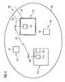
- Fig. 1illustrates the radio network 100 formed by a communication station 101 such as a base station (BS), and by a number of mobile communication terminals 102 to 104.
- a communication station 101such as a base station (BS)
- BSbase station
- mobile communication terminals 102 to 104a number of mobile communication terminals 102 to 104.
- a communication scheme between the mobile communication terminal 102 and the communication station 101will be explained in detail.
- a communication scheme performed between the communication station 101 and the mobile communication terminals 103, 104may be performed in a similar manner.
- the communication station 101may optionally be coupled to a central station and/or to one or more further communication stations by means of communication paths 106, 107, which may be wired, wireless or fibre optical connections.
- an operating distance 105is shown schematically in Fig. 1 , i.e. a range within which a communication between the communication station 101 and a plurality of mobile communication terminals 102 to 104 such as mobile phones is enabled with sufficient data transmission quality.
- the mobile communication terminal 102is adapted to be communicatively coupled to the communication station 101 of the communication network 100 and comprises a station communication unit 108 such as a sending and receiving antenna for bidirectionally exchanging communication messages with the communication station 101.
- the mobile communication terminal 102comprises a communication message generation unit 110 which is adapted for generating a Common Control Channel message (CCCH message) for transmission to the communication station 101 by the station communication unit 108.
- the communication message generation unit 110is further adapted for, if desired or necessary, rearranging the CCCH message in one or a plurality of Transmission Time Intervals (TTI) in accordance with the size of the CCCH message before transmission of the rearranged CCCH message to the communication station 101.
- TTITransmission Time Intervals
- the communication station 101is adapted to be communicatively coupled to the mobile communication terminal 102 and also to the mobile communication terminals 103, 104 of the communication network 100.
- the communication station 101comprises a terminal communication unit 114 such as a sender and receiver antenna adapted for bidirectionally exchanging communication messages with the mobile communication terminal 102, more particularly with the station communication unit 108 of the mobile communication terminal 102.
- the communication station 101comprises a communication message evaluation unit 116 which is adapted for evaluating a Common Control Channel message received from the mobile communication terminal 102 and being rearranged in one or a plurality of Transmission Time Intervals in accordance with a property of the Common Control Channel message.
- the mobile communication terminal 102 and the communication station 101are coordinated in such a manner that a rearrangement performed by the mobile communication terminal 102 can be interpreted by "reverse" processing by the communication station 101.
- the mobile communication terminal 102When the mobile communication terminal 102 prepares a CCCH message for transmission to the communication station 101, it analyzes the size of a corresponding message in view of a maximum or threshold data size. In case that it is recognized by the mobile communication terminal 102 that the maximum allowed size is exceeded, the CCCH message will, before transmission, be rearranged to meet the requirements of the communication scheme or protocol in the network 100. Particularly, the rearrangement may be performed in such a manner that a plurality of Transmission Time Intervals (TTI) are used for the message. However, rearrangement may also include restructuring, segmenting, deletion of unnecessary portions, compression, etc.
- TTITransmission Time Intervals
- the rearranged CCCH messageis then sent to the communication station 101.
- the rearranged transmitted CCCH messageis evaluated, that is particularly processed, etc. in order to extract the data content included therein. This may include procedures such as reassembling, disassembling, restructuring, decompressing, etc.
- Fig. 1shows an input/output unit 109 which may also be denoted as a user interface unit. Via such a user interface unit 109, a user may bidirectionally communicate with the mobile communication terminal 102.
- the input/output unit 109may comprise a keypad, buttons, etc., and/or may include a display on which results of a communication may be displayed.
- the input/output unit 113may serve, together with further components which are not shown in Fig. 1 , to allow to use the mobile communication terminal 102 as a mobile phone or cellular phone.
- HSUPAHigh Speed Random Access Channel
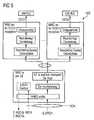
- a communication scheme 200according to an exemplary embodiment of the invention will be explained.
- a downlink portion 210is distinguished from an uplink portion 220.
- a high speed preamble in the uplink portion 220is denoted with reference numeral 230 in Fig. 2 .
- the described HS-RACH conceptmay be decomposed in several steps or phases, which are outlined below and which are indicated as well in Fig. 2 :
- restructuring, disassembly and segmentation/concatenationmay be performed in the MAC-e entity.
- the MAC-e entity in UE and Node Bare extended by functions allowing a separate handling of MAC-e and MAC-es PDUs carrying CCCH information.
- the MAC-e/es entity at the UE sideis extended by the following function:
- the MAC-e entity at the Node B sideis extended by following functions:
- the transport of a complete CCCH messageis provided by the MAC-e/es entities to the higher layers.
- Fig. 3illustrates a processing scheme 300 in accordance with the first embodiment (at the UE side).
- Fig. 4illustrates another processing scheme 400 in accordance with the first embodiment (at the Node B side).
- the TSN of the first MAC-es containing RLC PDU contentis set to a known value, for instance zero. With each subsequence MAC-es PDU, the TSN is incremented.
- SIScheduling Information
- the complete RLC PDUis present at the reassembly function and its delivery to the CCCH UL RLC entity is triggered.
- multiple "virtual" CCCH usersmay be involved, as will be described in the following:
- the pre-configurationcan be implementation specific, for instance establishment, maintenance and release can be left to operation and maintenance.
- the NBAPmay have to be extended to allow the RNC to notify the Node B/cell about the pre-configured triples (UM RLC, MAC-es, Iub data transport bearer) for CCCH reception.
- the UE id and Iub data transport channel demultiplexing functionmay also be advantageous for DCCHs and DTCHs in HS-RACH: for instance in CELL_FACH, a dedicated UE id, MAC-es entity and Iub data transport channel(s) are configured.
- a dedicated UE id, MAC-es entity and Iub data transport channel(s)are configured.
- the "UE id and Iub data transport channel demultiplexing" functionmay be advantageous for HS-RACH.
- Fig. 5illustrates a processing scheme 500 in accordance with the second embodiment.
- Fig. 5shows multiple pre-configured Iub data transport bearers, MAC-es and RLC entities for CCCH reception. If the logical channel id for CCCH reception is detected at MAC-e, the Node B selects one of the non-occupied MAC-d flows for MAC-es PDU transport. Each triple (RLC entity, MAC-es entity, Iub data transport bearer) for CCCH reception acts like a "virtually configured" EDCH user (Node B side).
- n MAC-es entities for CCCH receptionare pre-configured in the RNC for a cell/Node B.
- Each MAC-es entity for CCCH receptionhas a reordering and disassembly entity.
- Each MAC-es entity for CCCH receptionis connected with one preconfigured UM RLC entity.
- the HS-RACH procedureis started (step 1 to 5 of Fig. 2 ) as a CCCH message has to be transmitted.
- the UL transmission of the CCCH messageis part of step 6 as described referring to Fig. 2 .
- This mechanismguarantees that only the common data of a single UE are re-ordered in a reordering queue. As a consequence higher data volumes can be transmitted on the CCCH.
- multiple "virtual" CCCH channelsmay be implemented.
- UL data transmission for several configured logical channelsmay be supported in EDCH and HS-RACH.
- An aspect of the third embodimentis to process the CCCH data flow from several users as if coming from a single user with multiple priority flows configured, whereby each priority queue serves one CCCH transmitting UE.
- One MAC-es entity and one Iub data transport bearer to this entityare preconfigured. Every MAC-es PDU for the CCCH received at the cell/Node B is mapped on this Iub data transport bearer.
- the reordering queue distribution function in the MAC-esuses the logical channel id (and possible other attributes) included in the prepended MAC-es header to distribute the MAC-es PDUs to their reordering queue.
- a temporary UE idis send in the prepended MAC-es header.
- the temporary UE idis selected at the MAC-e entity, when a MAC-es PDU for CCCH has been received for the first time and is included to the preprended MAC-es header for all MAC-es PDUs for the CCCH, i.e. one temporary UE id and one reordering queue is used for a UE.
- the following extensionmay be done at the UE side:
- the Node Bmay signal to the RNC that the use of a temporary UE id has ended.
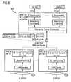
- Fig. 6illustrates a processing scheme 600 in accordance with the third embodiment.
- Fig. 6illustrates a single pre-configured Iub data bearer for CCCH reception. If the logical channel id for CCCH reception is detected at MAC-e, the Node B selects one of the non-used UE id values for MAC-es PDU transport. The MAC-es function reordering queue distribution forwards the MAC-es PDUs to the reordering queue associated with the UE id value, Node B side.
- one MAC-es entity for CCCH receptionis pre-configured in the RNC for a cell/Node B. In comprises one or several reordering and disassembly queues. Each queue is connected with one UM RLC entity. One Iub transport bearer pre-configured, which is linked to the MAC-es entity for CCCH reception.
- the HS-RACH procedureis started (step 1 to 5 of Fig. 2 ) as a CCCH message has to be transmitted.
- the UL transmission of the CCCH messageis part of step 6 as described referring to Fig. 2 .
- This mechanismguarantees that only the common data of a single UE are re-ordered in a reordering queue. As a consequence higher data volumes can be transmitted on the CCCH.
Landscapes
- Engineering & Computer Science (AREA)
- Computer Networks & Wireless Communication (AREA)
- Signal Processing (AREA)
- Mobile Radio Communication Systems (AREA)
Abstract
Description
- The present invention relates to the field of mobile communication terminals. Furthermore, the invention relates to communication stations. Moreover, the invention relates to communication networks. Beyond this, the invention relates to communication methods.
- Universal Mobile Telecommunications System (UMTS) is one of the third-generation (3G) mobile phone technologies. UMTS is a broadband, packet-based transmission of text, digitized voice, video, and multimedia at high data rates, offering a set of services to mobile computer and phone users no matter where they are located in the world.
- Document
US 2005/0266846 A1 discloses a method and apparatus for providing new configurations for transmitting control information between a mobile terminal and a network using a common control channel (CCCH) logical channel/transport channel. - There may be a need for a communication system providing a proper performance.
- This need may be met by a mobile communication terminal, by a communication station, by a communication network, and by a communication method according to the independent claims. Further embodiments of the present invention are described by the dependent claims.
- According to an exemplary embodiment, a mobile communication terminal (such as a cellular phone) adapted to be communicatively (for instance in a wireless manner) coupled to a communication station (such as a base station) of a communication network (such as an UMTS network) is provided, the mobile communication terminal comprising a station communication unit (such as an antenna) adapted for exchanging communication messages with the communication station, and a communication message generation unit (which may have processing capabilities) adapted for generating a Common Control Channel information comprising message for transmission to the communication station by the station communication unit, wherein the communication message generation unit is adapted for rearranging the Common Control Channel message (for instance in one or a plurality of Transmission Time Intervals, TTI) in accordance with a property (for instance a size, a type, a transmission protocol, a time duration, a priority, etc.) of the Common Control Channel information comprising message before transmission to the communication station.
- According to another exemplary embodiment, a communication station (such as a base station, for instance a node B) is provided which is adapted to be communicatively coupled (for instance for a wireless communication) to a mobile communication terminal of a communication network, wherein the communication station comprises a terminal communication unit (such as an antenna) adapted for exchanging communication messages with the mobile communication terminal, and a communication message evaluation unit (which may have processing capabilities) adapted for evaluating a Common Control Channel information comprising message received from the mobile communication terminal and being rearranged (for instance in one or a plurality of Transmission Time Intervals) in accordance with a property of the Common Control Channel information comprising message.
- According to still another exemplary embodiment, a communication network (for instance a radio network, particularly a UMTS network) is provided, the communication network comprising a mobile communication terminal having the above mentioned features and a communication station having the above mentioned features, wherein the mobile communication terminal is communicatively coupled to the communication station.
- According to yet another exemplary embodiment, a method of communicating in a communication network is provided, the communication method comprising communicatively coupling a mobile communication terminal to a communication station, generating, by the mobile communication terminal, a Common Control Channel information comprising message for transmission to the communication station, rearranging, by the mobile communication terminal, the Common Control Channel information comprising message (for instance in one or a plurality of Transmission Time Intervals) in accordance with a property of the Common Control Channel information comprising message before transmission to the communication station, and evaluating, by the communication station, the rearranged Common Control Channel information comprising message received from the mobile communication terminal.
- According to still another exemplary embodiment of the invention, a program element (for instance a software routine, in source code or in executable code) is provided, which, when being executed by a processor, is adapted to control or carry out at least a part of a communication method having the above mentioned features.
- According to yet another exemplary embodiment of the invention, a computer-readable medium (for instance a CD, a USB stick, a floppy disk or a harddisk) is provided, in which a computer program is stored which, when being executed by a processor, is adapted to control or carry out at least a part of a communication method having the above mentioned features.
- Data processing for communication purposes which may be performed according to embodiments of the invention can be realized by a computer program, that is by software, or by using one or more special electronic optimization circuits, that is in hardware, or in hybrid form, that is by means of software components and hardware components.
- In the context of this application, the term "mobile communication terminal" may particularly denote any user equipment, particularly portable communication device. This term may particularly include mobile phones, personal digital assistants (PDAs), navigation systems, etc.
- The term "communication station" may particularly denote any base station of a radio network. It may be coupled with one or a plurality of mobile communication terminals. Such a communication station may particularly be a base station (BS) in the context of UMTS (Universal Mobile Telecommunication Systems). Such a base station may be a central radio transmitter/receiver that may maintain communication with mobile radio telephones within a given range. The communication station may be installed at a fixed or stationary position.
- The term "communication unit" may particularly denote a transmitter, a receiver or a transmitter/receiver (transceiver) which allows for a unidirectional or bidirectional exchange of communication messages with a communication partner. Such a communication unit may particularly be a wireless communication unit, i.e. a communication system which communicates without the necessity of wires. However, wire-based communication is also covered by embodiments of the invention.
- The term "Common Control Channel information comprising message" may particularly denote a message comprising information which may be usually included in a Common Control Channel (CCCH) message, as defined below. Particularly, the Common Control Channel information comprising message may be a Common Control Channel (CCCH) message itself. Alternatively, the Common Control Channel information comprising message may be a Protocol Data Unit (PDA), more particularly a Radio Link Control Protocol Data Unit (RLC PDU), which may also include information which is typically included in a CCCH message. In specific embodiments, the CCCH information comprising message may be TM RLC PDU. The content of a CCCH message are its information elements.
- The term "Common Control Channel message" may particularly denote a control channel for a network such as a GSM network for use for initializing a communicative connection. Such a system, which may be implemented particularly in UMTS, may denote channels via which a mobile station or mobile communication terminal can be supplied with data/information regarding the network. Particularly, a mobile communication terminal may request allocation of a signalling channel via a CCCH channel. CCCH may support common procedures required to establish a dedicated link with the network and may include the RACH, FACH (Forward Access Channel) and PCH (paging channel).
- The term "Transmission Time Interval" (TTI) may particularly denote an inter-arrival time of a Transport Block Set (TBS), and may be equal to the periodicity at which a Transport Block Set may be transferred by a physical layer on a radio interface. A TTI may be a multiple of a minimum interleaving period (for instance 10 ms, which may be the length of one radio frame). A MAC (Medium Access Control) may deliver one transport block set to the physical layer every TTI.
- The term "rearranging" may particularly denote a change of the structure of the CCCH message. This may include a change in the order of components/blocks/segments of the message, a deletion of a portion of a message, extending a message by including additional information, assembling portions of the message to a larger message, etc. The term "rearranging" may include the concept of segmentation in transport.
- According to an exemplary embodiment of the invention, a communication scheme for communicating between a mobile communication terminal such as a cellular phone and a communication station such as a base station is provided, wherein the flexibility in designing a Common Control Channel information comprising message is increased by allowing a rearrangement of such a Common Control Channel message in dependence of the characteristics of the Common Control Channel information comprising message. For example, when the Common Control Channel message exceeds a predetermined threshold size/dimension, the rearrangement may be performed by splitting the Common Control Channel message into multiple portions, even involving multiple Transmission Time Intervals. Taking this measure may enable the transmission of Common Control Channel messages without or with relaxed restrictions regarding message size, and therefore content of such a message.
- According to an exemplary embodiment of the invention, a CCCH operation in HS-RACH may be enabled. In
step 6 of the communication scheme illustrated inFig. 2 , CCCH data can be sent. According to an exemplary embodiments of the invention, specific mechanisms for restructuring and segmentation of CCCH messages in HS-RACH procedure are provided. Such a restructuring and segmentation may enable the transmission of CCCH without message property restrictions in multiple TTIs. - More particularly, in WCDMA REL99 to REL7, following three CCCH messages are sent uplink:
- RRC CONNECTION REQUEST
- CELL UPDATE
- URA UPDATE
- According to an exemplary embodiment of the invention, the size of these messages is no more limited, so that they can be transmitted in a single TTI or in multiple TTIs. The segmentation of a CCCH message (that is one RLC SDU) in multiple RLC PDUs at the UE side and the combining of RLC PDUs to a single RLC SDU at the UTRAN side may be made possible. Different UEs can send RLC PDUs with the help of the RACH procedure at the same time, and for CCCH messages, an UE identifier may be included in MAC level. Therefore, UTRAN may be able to determine which PDUs should be combined together.
- According to an exemplary embodiment of the invention, a WCDMA system may be provided which does not prohibit sending large CCCH messages in multiple RACH TTIs in the UL, which relaxes limitations of the above mentioned messages. If this limitation does not exist, then larger CCCH messages can be sent in uplink direction, which can be for instance exploited to reduce the call setup delay by sending the RRC CONNECTION REQUEST and INITIAL DIRECT TRANSFER concatenated or their IEs combined in a single message. Additionally the CCCH message can include more uplink measurement results which are currently limited by the available message size.
- Particularly if HS-RACH is used, UL CCCH message segmentation may be enabled at the UM RLC entity instead of TM mode, or the segmentation is included at the MAC-e/es entity. The MAC-e/es entity may be used for restructuring.
- In the following, further exemplary embodiments of the mobile communication terminal will be explained. However, these embodiments also apply to the communication station, to the communication network and to the method.
- The communication message generation unit may be adapted for rearranging the Common Control Channel information comprising message in one or a plurality of Transmission Time Intervals (TTI) in accordance with a size of the Common Control Channel information comprising message. Particularly, a threshold data size of a Common Control Channel information comprising message may be defined. Even when such a threshold is exceeded, a transmission of the included data is possible, since the rearrangement may include the segmentation of the Common Control Channel information comprising message into a plurality of sub-portions, involving multiple Transmission Time Intervals, having a number in accordance with the required data size.
- Particularly, the communication message generation unit may segment the Common Control Channel information comprising message into a plurality of sub-messages which can be encoded in a plurality of Transmission Time Intervals. Such a segmentation may include a splitting of a data packet in a manner that it can be reassembled in accordance with a derivable scheme.
- The communication message generation unit may be adapted for rearranging the Common Control Channel information comprising message in accordance with a granted uplink (UL) resource per Transmission Time Interval. Thus, even when a granted uplink (UL) resource per Transmission Time Interval varies (for instance is increased in future technology generations), the system may flexibly adapt its function in accordance with the changes.
- The Common Control Channel message to be rearranged may be a Radio Resource Control Connection Request (RRC Connection Request) message. This may denote a procedure when a UE is in an idle mode and requests signalling connections. In this context, the UE may send an RRC Connection Request to the network. After receipt of an RRC Connection Setup message from the network, the UE may verify the UE identity. It may assume the state assigned by the network and may send a Connection Setup Complete message back.
- It is also possible that the Common Control Channel message to be processed is a Cell Update message. Cell Update may be used by an UE to inform an UTRAN that the UE has switched to a new cell. It may be a forward handover procedure. Such a procedure may be triggered after change of the cell and after the UE has read information transmitted by an UTRAN.
- Furthermore, it is possible that the Common Control Channel message is an URA Update (UTRAN Registration Area Update) message. An UTRAN Registration Area (URA) may be denoted as an area covered by a number of cells, wherein an URA may be configured in UTRAN and may be broadcasted in relevant cells. An URA Update message may be used by an UE to inform the UTRAN that the UE has switched to a new URA. It may be triggered after change of a cell, or after an UE has read information broadcasted by an UTRAN indicating a change of URA.
- Several cases may be distinguished:
- a) a CCCH message can be formed consisting of a RRC Connection Request message and an Initial Direct Transfer message, or
- b) a CCCH message can be formed consisting of a RRC Connection Request message, and RRC Connection Setup Complete and an Initial Direct Transfer message.
- A Medium Access Control (MAC) entity may be provided for transporting the Common Control Channel information comprising message. Medium Access Control may denote a lower one of two sub-layers in a Data Link Layer. MAC may handle access to a shared medium and may be employed in the context of UMTS.
- The mobile communication terminal may be adapted as a user equipment, particularly as a mobile phone. A mobile phone may be denoted as a device which behaves as a normal telephone while being able to move over a wide area. Mobile phones may allow connections to be made to the telephone network, normally bidirectionally dialling the other party's number on an in-built keypad. A mobile phone may also be denoted as a cellular telephone or a handheld mobile radio telephone for use in an area divided into sections, each with its own short range transmitter/receiver.
- The mobile communication terminal and/or the communication station may be adapted for a communication in accordance with UMTS, particularly with UTRAN (UMTS Terrestrial Radio Access Network). UTRAN may be denoted as a hierarchical network of several radio network subsystems (RMS), which may be interconnected to one another and with a core network.
- In the following, further exemplary embodiments of the communication station will be explained. However, these embodiments also apply to the mobile communication terminal, to the communication network and to the method.
- The communication message evaluation unit may further be adapted for evaluating the received Common Control Channel information comprising message by restructuring content of the received Common Control Channel message. This restructuring may be inverse to the restructuring at the side of the user equipment, so that the original information may be retrieved at the side of the communication station.
- Furthermore, disassembling of content of the Common Control Channel information comprising message may be performed by the communication station. This disassembling may include the separation of different components from a message, and may also include removal of a portion of a message, such as a header.
- Beyond this, the communication station may also perform a reassembling of the content of the Common Control Channel information comprising message. Such a function may reassemble segments to complete an interpretable message.
- The communication message evaluation unit may comprise a Medium Access Control (MAC) entity for transporting the Common Control Channel information comprising message. The configuration of a Medium Access Control entity at the side of the mobile communication terminal (that is the UE) and at the side of the communication station (that is of the base station) may be coordinated or harmonized, so that the corresponding protocols or schemes are in accordance to one another.
- It is possible that the Common Control Channel information comprising message is handled by a single (that is exactly one) Medium Access Control entity. Particularly, one Medium Access Control entity may be provided for all connected user equipments in common.
- Alternatively, the Common Control Channel information comprising message may be transported or handled by a selected one of a plurality of preconfigured Medium Access Control entities in the communication station. In other words, a plurality of MAC entities may be provided each of which being capable of handling the message, wherein a presently non-occupied one of the MAC entities may be used at a time for performing a transport task. By taking this measure, a fast and complete performance at the side of the communication station can be ensured even in the scenario in which a lot of traffic occurs, for instance caused by multiple CCCH or other messages.
- The communication station may also comprise a resource management unit adapted for queuing and subsequently working off multiple Common Control Channel information comprising messages received from a plurality of mobile communication terminals. In such a scenario, one MAC may be provided which serves several user equipments. In such a scenario, it may happen that several user equipments send a CCCH message at the same time. The management unit manages this data load and determines an order (for instance in accordance with the predetermined priority rule) to work off or process the individual messages.
- In the following, the term "CCCH information comprising message" will be discussed in further detail.
- According to one embodiment (which relates to the "first" embodiment below), TM RLC may be used for reordering, disassembly and segmentation/concatenation in the MAC-e entity. The TM RLC PDU provided by the TM RLC entity may be identical to the CCCH message.
- According to other embodiments (which relate to the "second" and "third" embodiment below), any CCCH message delivered by higher layers to the UM RLC entity may be segmented in the UM RLC entity. UM RLC headers may be added to each segment, and padding may be done to achieve octet alignment. Thus, the UM RLC PDU provided by the UM RLC entity to the lower layers is not an CCCH message in this case, but includes corresponding information.
- Therefore, in such embodiments "RLC PDU" (or "RLC PDU carrying CCCH message contents") may be considered as a "Common Control Channel information comprising message".
- One exemplary aspect is to allow segmentation of a PDU containing a CCCH message. As segments may be transmitted based on HARQ principles, this can lead to out of order delivery of the segments, requiring a reordering in the UTRAN.
- It has to be noted that embodiments of the invention have been described with reference to different subject matters. In particular, some embodiments have been described with reference to apparatus type claims whereas other embodiments have been described with reference to method type claims. However, a person skilled in the art will gather from the above and the following description that, unless otherwise notified, in addition to any combination of features belonging to one type of subject matter also any combination between features relating to different subject matters, in particular between features of the apparatus type claims and features of the method type claims is considered to be disclosed within this application.
- The aspects and exemplary embodiments defined above and further aspects of the invention are apparent from the example of embodiment to be described hereinafter and are explained with reference to these examples of embodiment.
Fig. 1 schematically shows a communication system according to an exemplary embodiment of the invention.Fig. 2 schematically shows a High Speed Random Access Channel (HS-RACH) procedure according to an exemplary embodiment of the invention.Fig. 3 schematically shows an exemplary embodiment of the invention involving CCCH PDU segmentation in MAC-e/es at the UE side.Fig. 4 schematically shows an exemplary embodiment of the invention involving CCCH PDU restructuring, disassembly and reassembly in a MAC-e entity, Node B side.Fig. 5 schematically shows an exemplary embodiment of the invention involving multiple pre-configured Iub data transport bearers, MAC-es and RLC entities for CCCH reception.Fig. 6 schematically shows an exemplary embodiment of the invention involving single pre-configured Iub data bearer for CCCH reception.- The illustration in the drawings is schematic. It is noted that in different figures, similar or identical elements are provided with the similar or identical reference signs.
- In the following, referring to
Fig. 1 , aradio network 100 according to an exemplary embodiment of the invention will be explained. Fig. 1 illustrates theradio network 100 formed by acommunication station 101 such as a base station (BS), and by a number ofmobile communication terminals 102 to 104.- In the following, a communication scheme between the
mobile communication terminal 102 and thecommunication station 101 will be explained in detail. A communication scheme performed between thecommunication station 101 and themobile communication terminals - As indicated schematically by
reference numerals communication station 101 may optionally be coupled to a central station and/or to one or more further communication stations by means ofcommunication paths - Furthermore, an
operating distance 105 is shown schematically inFig. 1 , i.e. a range within which a communication between thecommunication station 101 and a plurality ofmobile communication terminals 102 to 104 such as mobile phones is enabled with sufficient data transmission quality. - As can be taken from
Fig. 1 , themobile communication terminal 102 is adapted to be communicatively coupled to thecommunication station 101 of thecommunication network 100 and comprises astation communication unit 108 such as a sending and receiving antenna for bidirectionally exchanging communication messages with thecommunication station 101. Beyond this, themobile communication terminal 102 comprises a communicationmessage generation unit 110 which is adapted for generating a Common Control Channel message (CCCH message) for transmission to thecommunication station 101 by thestation communication unit 108. The communicationmessage generation unit 110 is further adapted for, if desired or necessary, rearranging the CCCH message in one or a plurality of Transmission Time Intervals (TTI) in accordance with the size of the CCCH message before transmission of the rearranged CCCH message to thecommunication station 101. - The
communication station 101 is adapted to be communicatively coupled to themobile communication terminal 102 and also to themobile communication terminals communication network 100. Thecommunication station 101 comprises aterminal communication unit 114 such as a sender and receiver antenna adapted for bidirectionally exchanging communication messages with themobile communication terminal 102, more particularly with thestation communication unit 108 of themobile communication terminal 102. Moreover, thecommunication station 101 comprises a communicationmessage evaluation unit 116 which is adapted for evaluating a Common Control Channel message received from themobile communication terminal 102 and being rearranged in one or a plurality of Transmission Time Intervals in accordance with a property of the Common Control Channel message. - In other words, the
mobile communication terminal 102 and thecommunication station 101 are coordinated in such a manner that a rearrangement performed by themobile communication terminal 102 can be interpreted by "reverse" processing by thecommunication station 101. - When the
mobile communication terminal 102 prepares a CCCH message for transmission to thecommunication station 101, it analyzes the size of a corresponding message in view of a maximum or threshold data size. In case that it is recognized by themobile communication terminal 102 that the maximum allowed size is exceeded, the CCCH message will, before transmission, be rearranged to meet the requirements of the communication scheme or protocol in thenetwork 100. Particularly, the rearrangement may be performed in such a manner that a plurality of Transmission Time Intervals (TTI) are used for the message. However, rearrangement may also include restructuring, segmenting, deletion of unnecessary portions, compression, etc. - Over a
communication path 120 within acommunication range 105, the rearranged CCCH message is then sent to thecommunication station 101. At the side of thecommunication station 101, the rearranged transmitted CCCH message is evaluated, that is particularly processed, etc. in order to extract the data content included therein. This may include procedures such as reassembling, disassembling, restructuring, decompressing, etc. - Moreover,
Fig. 1 shows an input/output unit 109 which may also be denoted as a user interface unit. Via such auser interface unit 109, a user may bidirectionally communicate with themobile communication terminal 102. Thus, the input/output unit 109 may comprise a keypad, buttons, etc., and/or may include a display on which results of a communication may be displayed. The input/output unit 113 may serve, together with further components which are not shown inFig. 1 , to allow to use themobile communication terminal 102 as a mobile phone or cellular phone. - Particularly in the context of the usage of E-DCH as RACH shared channel and a collision detection for a random access procedure, it may be advantageous to create a base for high speed and high data rate random access, further on called herein "High Speed Random Access Channel" (HS-RACH). It is believed that techniques of HSUPA, such as fast inner loop power control, varying bitrate, Node B scheduling with grants, fast ACK/NACK for DL transmission can be used already in the random access phase.
- When the UE sends a CCCH message while using HS-RACH, then following conditions may be fulfilled:
- The UE sends the RRC message RRC Connection Request, Cell Update or URA Update in REL7;
- The UE uses dedicated scrambling code for uplink transmission in HS-RACH. The scrambling code is not used by any other UE simultaneously after contention is solved.
- The MAC-e header contains a field which indicates the logical channel id (identifier) of the transmitted MAC-es PDU(s) .
- In REL7 this has been the DDI field (Data Description Identifier). For HS-RACH, a logical channel id field may be provided.
- The DDI value or logical channel id value for CCCH may be standardized or broadcasted as system information.
- The UE has to wait for a response from UTRAN before it can start sending any other UL data. In other words, when sending the CCCH message, there should only (MAC-es) PDUs in the E-DCH buffer carrying a CCCH message.
- If the Scheduling Indicator (SI) field is included in the MAC-e header, and the total E-DCH buffer (TDBS field in SI) in the UE is reported to be empty, then UTRAN is informed that the complete CCCH message has been transmitted.
- No Soft handover is supported for UL CCCH messages on HS-RACH as in Re199 RACH.
- In the following, referring to
Fig. 2 , acommunication scheme 200 according to an exemplary embodiment of the invention will be explained. In thecommunication scheme 200, adownlink portion 210 is distinguished from anuplink portion 220. A high speed preamble in theuplink portion 220 is denoted withreference numeral 230 inFig. 2 . - The described HS-RACH concept may be decomposed in several steps or phases, which are outlined below and which are indicated as well in
Fig. 2 : - (1) Determination of UL interference level for open loop power control
- (2) Release 99 random access procedure with power ramp-up using specific HS-RACH access slots and/or signatures indicated in SIB
- (3) Access Grant and Resource Assignment
- (4) Start of inner loop power control in UL, for instance on DPCCH.
- (5) Start of inner loop power control in DL, for instance on F-DPCH.
- (6) Start of UL data transmission, for instance on E-DPDCH/E-DPCCH
- (7) subsequent Resource Assignment (update of existing resource assignment) and Collision detection and resolution
- (8) ACK/NACK of UL data (ffs), for instance on E-HICH
- (9) ACK/NACK of DL data (ffs) and CQI for link adaptation (ffs), for instance on HS-DPCCH
- (10) Mechanisms at end of data transmission, end of HS-RACH resource allocation period, collision detection, etc.
- In the following, several possibilities for implementing exemplary embodiments of the invention will be explained.
- According to a first embodiment of the invention, restructuring, disassembly and segmentation/concatenation may be performed in the MAC-e entity.
- According to such an embodiment, the MAC-e entity in UE and Node B are extended by functions allowing a separate handling of MAC-e and MAC-es PDUs carrying CCCH information.
- For CCCH messages, the MAC-e/es entity at the UE side is extended by the following function:
- segmentation: The CCCH message is sent without segmentation from the TM RLC entity in the UE to the MAC-e/es entity of the UE. The segmentation is performed if the received RLC PDU is larger than the maximum allowed length of the MAC-es payload.
- TSN setting: The UE starts the numbering of the TSN from the known (predefined) value for CCCH messages.
- The MAC-e entity at the Node B side is extended by following functions:
- reordering/combining: This function reorders received MAC-es PDUs according to the received TSN and Node-B tagging (CFN, subframe number). MAC-es PDUs with consecutive TSNs are delivered to the disassembly function upon reception. As the first TSN value for CCCH message is known the MAC-e reordering can deliver all PDU having consecutive TSN value to the higher layers after receiving the known TSN value.
- disassembly: The disassembly function is responsible for disassembly of MAC-es PDUs. When a MAC-es PDU is disassembled the MAC-es header is removed, the MAC-es payload is extracted and delivered to concatenation function.
- reassembly: Reassembly function reassembles the MAC-es PDUs carrying segments of RLC PDU to complete RLC PDU
- According to the first embodiment, the transport of a complete CCCH message is provided by the MAC-e/es entities to the higher layers.
Fig. 3 illustrates aprocessing scheme 300 in accordance with the first embodiment (at the UE side).Fig. 4 illustrates anotherprocessing scheme 400 in accordance with the first embodiment (at the Node B side).- In the following, a procedural description of this first embodiment will be given.
- The transmission of a CCCH messages decomposes in following steps:
- The HS-RACH procedure is started (
steps 1 to 5 inFig. 2 ) as a CCCH message has to be transmitted. The UL transmission of the CCCH message is part ofstep 6 as described referring toFig. 2 . - The transparent RLC entity in the UE delivers the CCCH message without segmentation to the MAC-e/es entity.
- The MAC-e/es entity segments the RLC PDU, if it is larger than the maximum allowed length of the MAC-es payload.
- The multiplexing and TSN setting entity starts the setting of the TSN for first MAC-es/e PDU known value.
- In the next step, the HARQ entity is responsible for storing MAC-e payloads and re-transmitting them.
- The next steps continue at the UTRAN side.
- If a MAC-e PDU has been received by the HARQ entity, if forwards it to the De-multiplexing function.
- The de-mulitplexing function forwards the MAC-es PDU(s) to the reordering queue for CCCH. The identification of the reordering flow is done by a MAC-e field which identifies the logical channel (DDI or logical channel id).
- The Reordering function reorders received MAC-es PDUs according to the received TSN and Node-B tagging (CFN, subframe number). If a known value of the TSN is received the MAC-e PDU with consecutive TSN are immediately delivered to disassembly. Otherwise a normal reordering function is performed and with MAC-es PDUs with consecutive TSNs are delivered to the disassembly function upon reception and expiration of reordering timer such as T1.
- The disassembly function removes the MAC-es header and forwards the MAC-es SDUs to the reassembly function.
- The reassembly function combines the MAC-es SDUs. After receiving the complete RLC PDU it delivers it to the higher layers (i.e. it forwards it to the CCCH TM RLC).
- When an RLC PDU is transmitted, the TSN of the first MAC-es containing RLC PDU content is set to a known value, for instance zero. With each subsequence MAC-es PDU, the TSN is incremented. When the last part of the RLC PDU is transmitted in a MAC-es PDU, then the Scheduling Information (SI) has to be added, which informs the Node B that the total E-DCH buffer is empty. In other words, the complete RLC PDU has been delivered. If the MAC-es/e PDU(s) carried on this last MAC-es entity are delivered to the reassembly function, the complete RLC PDU is present at the reassembly function and its delivery to the CCCH UL RLC entity is triggered.
- According to a second embodiment of the invention, multiple "virtual" CCCH users may be involved, as will be described in the following:
- HS-RACH feature aims to allow UEs in CELL_FACH state to have EDCH resources configured, i.e. for each logical channel, an RLC entity and MAC-es reordering queue are configured as well as one or several Iub data transport bearers from the Node B to the MAC-es entity. When running HS-RACH, the Node B grants EDCH radio resources to the UE. The UE sends its UL data; at the Node B the received MAC-es PDUs are mapped on the Iub data transport bearer(s) configured for this UE, transported to the UE's configured MAC-es entity, and reordered in the reordering queues.
- One aspect regarding virtual CCCH users is to pre-configure multiple EDCH resources for CCCH reception, with one EDCH resource consisting of one RLC entity, one MAC-es reordering queue and one Iub data transport bearer. If a UE sends CCCH data, then the MAC-e selects one of the unused EDCH resources for CCCH reception. The transport and processing of MAC-e and MAC-es PDUs is then identical to the case where dedicated EDCH resources exist.
- To send a CCCH message, following extension may be done at the UE side:
- The segmentation at UM RLC entity for CCCH is configured instead of TM RLC.
- No modification for MAC-es/e
- To receive a CCCH message, following mechanisms and extensions may be performed at the UTRAN side:
- Pre-configuration of multiple UM RLC entities, MAC-es entities and Iub transport bearer. In detail: N triples (UM RLC, MAC-es, Iub data transport bearer) for CCCH reception are pre-configured in UTRAN:
- UM RLC entity for CCCH reception: The UM RLC entity receives RLC PDUs, reassembles them and forwards CCCH messages to the RRC entity.
- MAC-es entity for CCCH reception: The MAC-es entity for CCCH reception has the same functions defined as in REL6/7. The MAC-es entity provides its services to the higher layer UM RLC entity for CCCH reception, i.e. it forwards RLC PDUs to it.
- Iub data transport bearer: An AAL2 Binding Identity is used to bind the Iub Data Transport Bearer to E-DCH. The Iub data transport bearer provided MAC-es PDU transport channel to the MAC-es entity for CCCH reception.
- The pre-configuration can be implementation specific, for instance establishment, maintenance and release can be left to operation and maintenance.
- The NBAP may have to be extended to allow the RNC to notify the Node B/cell about the pre-configured triples (UM RLC, MAC-es, Iub data transport bearer) for CCCH reception.
- - MAC-e entity extension:
- UE id and Iub data transport channel demultiplexing:
When granting EDCH resources to a UE during the HS-RACH procedure, the Node B automatically establishes a MAC-e entity for this UE. If a MAC-e PDU is received, and a field (for instance logical channel id or DDI) in the MAC-e header links the uplink transmission to CCCH, then- the Node B selects one of the Iub data transport bearer for CCCH reception from a pool of non-occupied Iub data transport bearer for CCCH reception - the selected Iub data transport bearer is marked as occupied - and then
- transmits all MAC-es PDUs for the logical channel CCCH on this Iub data transport bearer till the HS-RACH radio resources are released for this UE. After the release of the HS-RACH radio resources, the Iub data transport bearer for CCCH reception is returned to the pool of non-occupied Iub data transport bearer for CCCH reception.
- The UE id and Iub data transport channel demultiplexing function may also be advantageous for DCCHs and DTCHs in HS-RACH: for instance in CELL_FACH, a dedicated UE id, MAC-es entity and Iub data transport channel(s) are configured. As soon as the UE identity is available at the MAC-e entity with the first successful reception of a MAC-e PDU, all received MAC-e PDUs must be multiplexed on the dedicated Iub data transport channel(s) for this UE. Therefore, the "UE id and Iub data transport channel demultiplexing" function may be advantageous for HS-RACH.
Fig. 5 illustrates aprocessing scheme 500 in accordance with the second embodiment.Fig. 5 shows multiple pre-configured Iub data transport bearers, MAC-es and RLC entities for CCCH reception. If the logical channel id for CCCH reception is detected at MAC-e, the Node B selects one of the non-occupied MAC-d flows for MAC-es PDU transport. Each triple (RLC entity, MAC-es entity, Iub data transport bearer) for CCCH reception acts like a "virtually configured" EDCH user (Node B side).- In the following, a procedural description of the second embodiment will be given.
- By operation and maintenance, n MAC-es entities for CCCH reception are pre-configured in the RNC for a cell/Node B. Each MAC-es entity for CCCH reception has a reordering and disassembly entity. For each MAC-es entity for CCCH reception there is one Iub transport bearer pre-configured. Each MAC-es entity for CCCH reception is connected with one preconfigured UM RLC entity.
- The HS-RACH procedure is started (
step 1 to 5 ofFig. 2 ) as a CCCH message has to be transmitted. The UL transmission of the CCCH message is part ofstep 6 as described referring toFig. 2 . - UE operation:
- 1. The UM RLC entity for CCCH transmission segments the RRC SDU into sizes suitable for MAC-es/e, if needed. The segments are forwarded as RLC PDUs to the MAC-es/e entity. The operation in the MAC-es/e side of the UE continues as in REL6/7.
- Node B operation:
- 1. The HS-RACH procedure is started (
step 1 to 5 ofFig. 2 ) as a CCCH message has to be transmitted. The UL transmission of the CCCH message is part ofstep 6 as described referring toFig. 2 . - 2. The first successfully received MAC-es PDU contains a UE identity and logical channel information (for instance in DDI-field, or equivalent field depending on MAC-e header evolution for REL8). After determining the logical channel id, the Node B knows that the UE sends data for the CCCH.
- 3. The Node B selects one of the Iub transport bearers to a MAC-es entity for CCCH reception, which is currently not used for CCCH data transport. The Node B uses this Iub transport bearer exclusively for this UE for the duration of the HS-RACH procedure. When the HS-RACH procedure ends, and physical resources granted on the radio interface are released, then this Iub transport bearer and its connected MAC-es entity for CCCH reception can be used for another UE requesting transport of CCCH data.
Neither the Iub transport bearer nor its MAC-es entity for CCCH reception have to be released after releasing the HS-RACH resources for a UE.
When the HS-RACH procedure ends, the Node B may signal this to the RNC, so that any buffered MAC-es PDU in the MAC-es entity is discarded, and any buffered RLC PDUs in the UM RLC entity are delivered to the higher layer/ or discarded. - 4. At the MAC-es for CCCH entity reception reordering/combining and disassembly takes place as in REL6/7.
- 5. Each MAC-es for CCCH entity is connected to one UM RLC entity which concatenates all received RLC PDUs, before forwarding them to the higher layer.
- This mechanism guarantees that only the common data of a single UE are re-ordered in a reordering queue. As a consequence higher data volumes can be transmitted on the CCCH.
- According to a third embodiment of the invention, multiple "virtual" CCCH channels may be implemented.
- UL data transmission for several configured logical channels may be supported in EDCH and HS-RACH.
- An aspect of the third embodiment is to process the CCCH data flow from several users as if coming from a single user with multiple priority flows configured, whereby each priority queue serves one CCCH transmitting UE. One MAC-es entity and one Iub data transport bearer to this entity are preconfigured. Every MAC-es PDU for the CCCH received at the cell/Node B is mapped on this Iub data transport bearer. The reordering queue distribution function in the MAC-es uses the logical channel id (and possible other attributes) included in the prepended MAC-es header to distribute the MAC-es PDUs to their reordering queue. Instead of the logical channel id, a temporary UE id is send in the prepended MAC-es header. The temporary UE id is selected at the MAC-e entity, when a MAC-es PDU for CCCH has been received for the first time and is included to the preprended MAC-es header for all MAC-es PDUs for the CCCH, i.e. one temporary UE id and one reordering queue is used for a UE.
- To send a CCCH message, the following extension may be done at the UE side:
- The segmentation at UM RLC entity for CCCH is configured instead of TM RLC
- No modification for MAC-es/e
- To receive a CCCH message, following mechanisms and extensions may be performed at the UTRAN side:
- Iub data transport bearer for CCCH reception: One Iub data transport bearer for CCCH reception is configured. On this bearer, only MAC-es PDUs carrying UL CCCH information are transmitted. Each transmitted MAC-es PDU is accompanied by a so called "prepended MAC-es PDU header", which includes a UE identity field: In CELL_DCH state, this field contains the logical channel id, etc. As every MAC-es PDU on this channel is carrying data for the logical channel CCCH, the bits of these field can be used to inform the receiver (MAC-es/RNC) that all MAC-es PDUs with the same id originated from a single UE.
- MAC-e entity extension: UE id and Iub data transport channel demultiplexing: When granting EDCH resources to a UE during the HS-RACH procedure, the Node B automatically establishes a MAC-e entity for this UE. If a MAC-e PDU is received, and a logical channel id in the MAC-e header links the MAC-es PDU in the MAC-e PDU payload part to CCCH, then this function is used to
- select a temporary UE id from a pool of non-used identity values; This value is marked as used, and is used for this UE for the duration of the HS-RACH procedure; and then
- multiplexes all MAC-es PDUs for the logical channel CCCH on the pre-configured Iub data transport bearer for CCCH reception. Hereby the prepended MAC-es header has the temporary UE id included.
- After the release of the HS-RACH radio resources, the temporary UE id is marked as non-used.
- The Node B may signal to the RNC that the use of a temporary UE id has ended.
- MAC-es extension in the RNC: There is one MAC-es entity for CCCH reception. The UE id in the prepended MAC-es header is used to route the MAC-es entity to the correct reordering queue, consisting of the reordering/combining and the disassembly function. If a MAC-es PDU header contains a previous unused UE id, then the RNC may create a new reordering queue and a new RLC entity for this UE id. If no MAC-es PDU for an existing reordering queue for a UE id appears for a defined period of time, or if (alternatively) the Node B signals that the UE id for an existing reordering queue is no longer used, then the reordering queue may be released, and any stored MAC-es PDUs are discarded. Also the RLC entity is released.
- UM RLC for CCCH reception: This entity supports the concatenation of RLC PDUs received by a priority queue of a MAC-es entity for CCCH reception.
Fig. 6 illustrates aprocessing scheme 600 in accordance with the third embodiment.Fig. 6 illustrates a single pre-configured Iub data bearer for CCCH reception. If the logical channel id for CCCH reception is detected at MAC-e, the Node B selects one of the non-used UE id values for MAC-es PDU transport. The MAC-es function reordering queue distribution forwards the MAC-es PDUs to the reordering queue associated with the UE id value, Node B side.- Next, a procedural description in accordance with the third embodiment will be explained.
- By operation and maintenance, one MAC-es entity for CCCH reception is pre-configured in the RNC for a cell/Node B. In comprises one or several reordering and disassembly queues. Each queue is connected with one UM RLC entity. One Iub transport bearer pre-configured, which is linked to the MAC-es entity for CCCH reception.
- The HS-RACH procedure is started (
step 1 to 5 ofFig. 2 ) as a CCCH message has to be transmitted. The UL transmission of the CCCH message is part ofstep 6 as described referring toFig. 2 . - UE operation:
- 1. The UM RLC entity for CCCH transmission segments the RRC SDU into sizes suitable for MAC-es/e, if needed. The segments are forwarded as RLC PDUs to the MAC-es/e entity. The operation in the MAC-es/e side of the UE continues as in REL6/7.
Node B operation: - 2. The first successfully received MAC-es PDU contains a UE identity and logical channel information (for instance in DDI-field, or equivalent field depending on MAC-e header evolution for REL8). After determining the logical channel id, the Node B knows that the UE sends data for the CCCH.
- 3. The Node B selects one of the "temporary UE ids" for CCCH reception within the set of available "temporary UE ids", which is currently not used by other MAC-e entities in the cell/Node B for CCCH data transport. The Node B uses this temporary UE id exclusively for this UE for the duration of the HS-RACH procedure. Each MAC-es PDU for CCCH received at the MAC-e entity is mapped on the preconfigured Iub data transport channel for CCCH. In the prepended MAC-es header, the temporary UE id is included.
When the HS-RACH procedure ends, and physical resources granted on the radio interface are released, then this temporary UE id can be used for another UE requesting transport of CCCH data. Neither the Iub transport bearer nor its MAC-es entity for CCCH reception have to be released after releasing the HS-RACH resources for a UE. When the HS-RACH procedure ends, the Node B may signal this to the RNC, so that any buffered MAC-es PDU in the MAC-es entity is discarded, and any buffered RLC PDUs in the UM RLC entity are delivered to the higher layer/ or discarded. - 4. At the MAC-es for CCCH entity the reordering queue distribution function is used to distribute the incoming MAC-es PDUs according to their temporary UE id. Then reordering/combining and disassembly takes place as in REL6/7.
In REL6/7, reordering queue distribution function is based on the DDI value. No modification of the reordering queue distribution function is performed, if for instance the temporary UE id is placed in the DDI field. - 5. Each reordering and disassembly queue is connected to one UM RLC entity which concatenates all received RLC PDUs, before forwarding them to the higher layer.
- This mechanism guarantees that only the common data of a single UE are re-ordered in a reordering queue. As a consequence higher data volumes can be transmitted on the CCCH.
- Finally, it should be noted that the above-mentioned embodiments illustrate rather then limit the invention, and that those skilled in the art will be capable of designing many alternative embodiments without departing from the scope of the invention as defined by the appended claims. In the claims, any reference signs shall not be construed as limiting the claims. The word "comprising" and "comprises", and the like, does not exclude the presence of elements or steps other than those listed in any claim or the specification as a whole. The singular reference of an element does not exclude the plural reference of such elements and vice-versa. In a device claim enumerating several means, several of these means may be embodied by one and the same item of software or hardware. The mere fact that certain measures are recited in mutually different dependent claims does not indicate that a combination of these measures cannot be used to advantage.
- 100
- radio network
- 101
- communication station
- 102
- mobile communication terminal
- 103
- mobile communication terminal
- 104
- mobile communication terminal
- 105
- operating distance
- 106
- communication path
- 107
- communication path
- 108
- terminal communication unit
- 109
- user interface
- 110
- communication message generation unit
- 114
- station communication unit
- 116
- communication message evaluation unit
- 120
- communicative coupling
- 200
- communication scheme
- 210
- downlink portion
- 220
- uplink portion
- 230
- high speed preamble
- 300
- processing scheme
- 400
- processing scheme
- 500
- processing scheme
- 600
- processing scheme
- AC
- Access Class
- ACK
- acknowledged
- AI
- Acquisition Indicator
- AICH
- Acquisition indicator channel
- ASC
- Access Service Class
- CCCH
- Common Control Channel
- CQI
- Channel Quality Indicator
- DDI
- Data Description Indicator
- DPCCH
- Dedicated Physical Control Channel
- DPDCH
- Dedicated Physical Data Channel
- DL
- downlink
- E-DCH
- Enhanced Dedicated Channel
- E-DPCCH
- Enhanced Dedicated Physical Control Channel
- E-DPDCH
- Enhanced Dedicated Physical Data Channel
- E-HICK
- Enhanced Hybrid Automatic Request Indication Channel
- F-DPCCH
- Fractional Dedicated Physical Control Channel
- MAC
- Medium Access Control
- MAC-e
- Medium Access Control entity for EDCH in Node B
- MAC-es
- Medium Access Control entity for EDCH in RNC
- MAC-es/e
- Medium Access Control entity for EDCH in UE
- NACK
- non-acknowledged
- HS-RACH
- High Speed Random Access Channel
- HS-SCCH
- High Speed - Shared Control Channel
- HSDPA
- High Speed Downlink Packet Access
- HSUPA
- High Speed Uplink Packet Access
- PDU
- Protocol Data Unit
- PRACH
- Physical Random Access Channel
- RACH
- Random Access Channel
- RLC
- Radio Link Control
- RRC
- Radio Resource Control
- SI
- Scheduling Information
- SDU
- Service Data Unit
- TSN
- Transmission Sequence Number
- TTI
- Transmission Time Interval
- UE
- User Equipment
- UL
- uplink
- URA
- UTRAN Registration Area
- WCDMA
- Wideband Code Division Multiple Access
Claims (19)
- A mobile communication terminal (102) adapted to be communicatively coupled to a communication station (101) of a communication network (100), the mobile communication terminal (102) comprising:a station communication unit (108) adapted for exchanging communication messages with the communication station (101);a communication message generation unit (110) adapted for generating a Common Control Channel information comprising message for transmission to the communication station (101) by the station communication unit (108);characterised by the communication message generation unit (110) being adapted for rearranging the Common Control Channel information comprising message in a plurality of Transmission Time Intervals in accordance with a property of the Common Control Channel information comprising message before transmission to the communication station (101).
- The mobile communication terminal (102) according to claim 1,
wherein the communication message generation unit (110) is adapted for rearranging the Common Control Channel information comprising message in accordance with a size of the Common Control Channel information comprising message. - The mobile communication terminal (102) according to claim 1 or 2,
wherein the communication message generation unit (110) is adapted for rearranging the Common Control Channel information comprising message in accordance with a granted uplink resource per Transmission Time Interval. - The mobile communication terminal (102) according to any one of claims 1 to 3,
wherein the communication message generation unit (110) is adapted for rearranging the Common Control Channel information comprising message in at least one manner of the group consisting of segmenting the Common Control Channel information comprising message, and restructuring the Common Control Channel information comprising message. - The mobile communication terminal (102) according to any one of claims 1 to 4,
wherein the Common Control Channel information comprising message is one of the group consisting of a Common Control Channel message, and a Radio Link Control Protocol Data Unit. - The mobile communication terminal (102) according to claim 5,
wherein the Common Control Channel message is one of the group consisting of a Radio Resource Control Connection Request message, a Cell Update message, and a Universal Mobile Telecommunications System Terrestrial Radio Access Network Registration Area Update message. - The mobile communication terminal (102) according to any one of claims 1 to 8,
comprising a Medium Access Control entity adapted for transporting the Common Control Channel information comprising message. - The mobile communication terminal (102) according to any one of claims 1 to 7,
adapted as a user equipment, particularly as a mobile phone. - The mobile communication terminal (102) according to any one of claims 1 to 8,
adapted for a communication in accordance with a Universal Mobile Telecommunications System protocol, particularly in accordance with a Universal Mobile Telecommunications System Terrestrial Radio Access Network protocol. - A communication station (101) adapted to be communicatively coupled to a mobile communication terminal (102) of a communication network (100), the communication station (101) comprising:a terminal communication unit (114) adapted for exchanging communication messages with the mobile communication terminal (102);characterised by a communication message evaluation unit (116) adapted for evaluating a Common Control Channel information comprising message received from the mobile communication terminal (102) and being rearranged in a plurality of Transmission Time Intervals in accordance with a property of the Common Control Channel information comprising message.
- The communication station (101) according to claim 10, wherein the communication message evaluation unit (116) is adapted for evaluating the received Common Control Channel information comprising message in at least one manner of the group consisting of restructuring content of the received Common Control Channel information comprising message, combining content of the received Common Control Channel information comprising message, disassembling content of the received Common Control Channel information comprising message, and reassembling content of the received Common Control Channel information comprising message.
- The communication station (101) according to claim 10 or claim 11,
wherein the Common Control Channel information comprising message is one of the group consisting of a Common Control Channel message, and a Radio Link Control Protocol Data Unit. - The communication station (101) according to claim 12, wherein the Common Control Channel message is one of the group consisting of a Radio Resource Control Connection Request message, a Cell Update message, and a Universal Mobile Telecommunications System Terrestrial Radio Access Network Registration Area Update message.
- The communication station (101) according to any one of claims 10 to 13,
comprising a Medium Access Control entity for transporting the Common Control Channel information comprising message. - The communication station (101) according to any one of claims 10 to 14,
comprising a plurality of preconfigured Medium Access Control entities for transporting the Common Control Channel information comprising message. - The communication station (101) according to any one of claims 10 to 15,
comprising a management unit adapted for queuing and subsequently working off a plurality of Common Control Channel information comprising messages received from a plurality of mobile communication terminals (102). - The communication station (101) according to any one of claims 10 to 16,
adapted for a communication in accordance with a Universal Mobile Telecommunications System protocol, particularly in accordance with a Universal Mobile Telecommunications System Terrestrial Radio Access Network protocol. - A communication network (100), the communication network (100) comprising
a mobile communication terminal (102) according to any one of claims 1 to 9;
a communication station (101) according to any one of claims 10 to 17;
wherein the mobile communication terminal (102) is communicatively coupled to the communication station (101). - A method of communicating in a communication network (100), the method comprising
communicatively coupling a mobile communication terminal (102) to a communication station (101);
generating, by the mobile communication terminal (102), a Common Control Channel information comprising message for transmission to the communication station (101);
characterised by rearranging, by the mobile communication terminal (102), the Common Control Channel information comprising message in a plurality of Transmission Time Intervals in accordance with a property of the Common Control Channel information comprising message before transmission to the communication station (101);
evaluating, by the communication station (101), the rearranged Common Control Channel information comprising message received from the mobile communication terminal (102).
Priority Applications (9)
| Application Number | Priority Date | Filing Date | Title |
|---|---|---|---|
| AT07015719TATE510441T1 (en) | 2007-08-09 | 2007-08-09 | MOBILE COMMUNICATION TERMINAL, COMMUNICATION STATION, COMMUNICATION NETWORK AND COMMUNICATION METHOD |
| EP07015719AEP2023683B1 (en) | 2007-08-09 | 2007-08-09 | Mobile communication terminal, communication station, communication network, and communication method |
| CN200880110723ACN101822116A (en) | 2007-08-09 | 2008-07-31 | Mobile communication terminal, communication station, communication network, and communication method |
| BRPI0814959ABRPI0814959A8 (en) | 2007-08-09 | 2008-07-31 | MOBILE COMMUNICATION TERMINAL, COMMUNICATION STATION, COMMUNICATION NETWORK, AND COMMUNICATION METHOD |
| MX2010001521AMX2010001521A (en) | 2007-08-09 | 2008-07-31 | MOBILE COMMUNICATION TERMINAL, COMMUNICATION STATION, COMMUNICATION NETWORK AND COMMUNICATION METHODS. |
| US12/733,134US20100285791A1 (en) | 2007-08-09 | 2008-07-31 | Mobile communication terminal, communication station, communication network, and communication method |
| PCT/EP2008/060097WO2009019198A1 (en) | 2007-08-09 | 2008-07-31 | Mobile communication terminal, communication station, communication network, and communication method |
| AU2008285753AAU2008285753B2 (en) | 2007-08-09 | 2008-07-31 | Mobile communication terminal, communication station, communication network, and communication method |
| TW097129980ATWI442804B (en) | 2007-08-09 | 2008-08-07 | Mobile communication terminal, communication station, communication network and communication method |
Applications Claiming Priority (1)
| Application Number | Priority Date | Filing Date | Title |
|---|---|---|---|
| EP07015719AEP2023683B1 (en) | 2007-08-09 | 2007-08-09 | Mobile communication terminal, communication station, communication network, and communication method |
Publications (2)
| Publication Number | Publication Date |
|---|---|
| EP2023683A1 EP2023683A1 (en) | 2009-02-11 |
| EP2023683B1true EP2023683B1 (en) | 2011-05-18 |
Family
ID=38895994
Family Applications (1)
| Application Number | Title | Priority Date | Filing Date |
|---|---|---|---|
| EP07015719AActiveEP2023683B1 (en) | 2007-08-09 | 2007-08-09 | Mobile communication terminal, communication station, communication network, and communication method |
Country Status (9)
| Country | Link |
|---|---|
| US (1) | US20100285791A1 (en) |
| EP (1) | EP2023683B1 (en) |
| CN (1) | CN101822116A (en) |
| AT (1) | ATE510441T1 (en) |
| AU (1) | AU2008285753B2 (en) |
| BR (1) | BRPI0814959A8 (en) |
| MX (1) | MX2010001521A (en) |
| TW (1) | TWI442804B (en) |
| WO (1) | WO2009019198A1 (en) |
Families Citing this family (11)
| Publication number | Priority date | Publication date | Assignee | Title |
|---|---|---|---|---|
| CN104837204A (en) | 2007-09-28 | 2015-08-12 | 交互数字专利控股公司 | Method and apparatus for terminating message transmission on enhanced random access channel |
| KR20100089883A (en)* | 2007-10-25 | 2010-08-12 | 인터디지탈 패튼 홀딩스, 인크 | Methods and apparatuses for management and setup of enhanced mac-e/es resources in cell-fach state |
| EP2238784B1 (en) | 2008-01-02 | 2022-06-01 | RnB Wireless LLC | Methods, system and apparatus for cell reselection |
| US9689685B2 (en) | 2010-01-21 | 2017-06-27 | Qualcomm Incorporated | Methods and apparatuses for use in route navigation involving a mobile station |
| EP2557870B1 (en)* | 2011-08-10 | 2020-07-08 | Alcatel Lucent | Configuring transmissions |
| CN103037314B (en)* | 2011-09-30 | 2016-03-09 | 国际商业机器公司 | The method of pocket transmission news on the mobile terminal in autonomous network |
| US9613211B1 (en)* | 2012-12-10 | 2017-04-04 | Symantec Corporation | Systems and methods for identifying suspicious text-messaging applications on mobile devices |
| WO2015012638A1 (en)* | 2013-07-25 | 2015-01-29 | Samsung Electronics Co., Ltd. | Scheme for transmitting and receiving information in wireless communication system |
| US10517011B2 (en)* | 2014-11-13 | 2019-12-24 | Telefonaktiebolaget Lm Ericsson (Publ) | Automated measurement and analysis of end-to-end performance of VoLTE service |
| US20160150522A1 (en)* | 2014-11-21 | 2016-05-26 | Qualcomm Incorporated | Uplink resource management during radio link control (rlc) transmission window full state |
| US11317462B2 (en)* | 2018-11-05 | 2022-04-26 | Apple Inc. | Apparatus, systems, and methods for transmitting large network configuration messages |
Family Cites Families (63)
| Publication number | Priority date | Publication date | Assignee | Title |
|---|---|---|---|---|
| JPH07107994B2 (en)* | 1992-08-27 | 1995-11-15 | 日本電気株式会社 | Access method |
| US6477377B2 (en)* | 1998-05-29 | 2002-11-05 | Ericsson Inc. | Cellular radiotelephone systems and methods that broadcast a common control channel over multiple radio frequencies |
| FI114077B (en)* | 1999-03-10 | 2004-07-30 | Nokia Corp | ID booking method |
| GB9913221D0 (en)* | 1999-06-07 | 1999-08-04 | Nokia Telecommunications Oy | Cell update in a cellular communications system |
| PT1357675E (en)* | 1999-06-25 | 2006-10-31 | Samsung Electronics Co Ltd | APPARATUS AND METHOD FOR CODING AND MULTIPLEXING OF CHANNELS IN A CDMA COMMUNICATION SYSTEM |
| FI109255B (en)* | 2000-04-07 | 2002-06-14 | Nokia Corp | Numbering of data packets during packet switching data transfer |
| KR100469735B1 (en)* | 2000-07-18 | 2005-02-02 | 삼성전자주식회사 | Call admission method in cdma mobile communication system |
| US6917612B2 (en)* | 2000-09-01 | 2005-07-12 | Telefonaktiebolaged L M Ericsson | System and method for address resolution in internet protocol (IP)-based networks |
| KR100662286B1 (en)* | 2000-11-30 | 2007-01-02 | 엘지전자 주식회사 | Method of transmitting protocol data unit in radio link control layer and radio communication system having radio link control layer |
| CA2376962A1 (en)* | 2001-04-02 | 2002-10-02 | Lucent Technologies Inc. | Method and system for umts packet transmission scheduling on uplink channels |
| JP4643139B2 (en)* | 2001-06-12 | 2011-03-02 | テレフオンアクチーボラゲット エル エム エリクソン(パブル) | Synchronization in the UMTS Terrestrial Radio Access Network (UTRAN) |
| US7260077B2 (en)* | 2001-06-18 | 2007-08-21 | Nortel Networks Limited | Adaptive scheduling for multi-carrier systems |
| US6892199B2 (en)* | 2001-06-29 | 2005-05-10 | Trendium, Inc. | Saving burst data by using semi-merge sorting module |
| EP1289328A1 (en)* | 2001-08-28 | 2003-03-05 | Lucent Technologies Inc. | A method of sending control information in a wireless telecommunications network, and corresponding apparatus |
| WO2004015909A1 (en)* | 2002-08-01 | 2004-02-19 | Nokia Corporation | Transmitting interleaved multiple data flows |
| US6788963B2 (en)* | 2002-08-08 | 2004-09-07 | Flarion Technologies, Inc. | Methods and apparatus for operating mobile nodes in multiple a states |
| TW200408242A (en)* | 2002-09-06 | 2004-05-16 | Matsushita Electric Industrial Co Ltd | Home terminal apparatus and communication system |
| CN1245842C (en)* | 2002-11-29 | 2006-03-15 | 华为技术有限公司 | System information receiving and reassembling method in the third generation wireless communication system |
| US20060223532A1 (en)* | 2003-04-03 | 2006-10-05 | Sheng Liu | Method for user equipment mobility management and communication system |
| JP4466188B2 (en)* | 2003-07-16 | 2010-05-26 | 株式会社デンソー | Vehicle control device |
| KR100735277B1 (en)* | 2003-07-30 | 2007-07-03 | 삼성전자주식회사 | Ranging method in broadband wireless access communication system |
| KR100976475B1 (en)* | 2003-08-19 | 2010-08-18 | 엘지전자 주식회사 | Quality of Service (QoS) measurement report transmission method and reception method |
| GB0323244D0 (en)* | 2003-10-03 | 2003-11-05 | Fujitsu Ltd | Uplink scheduling |
| GB0323199D0 (en)* | 2003-10-03 | 2003-11-05 | Fujitsu Ltd | Soft handover |
| EP1533932A1 (en)* | 2003-11-19 | 2005-05-25 | Mitsubishi Denki Kabushiki Kaisha | Error control mechanism for a segment based link layer in a digital network |
| KR100575925B1 (en)* | 2003-12-04 | 2006-05-02 | 삼성전자주식회사 | Rate matching method and apparatus for multiplexing channels having different transmission time intervals in a mobile communication system |
| US7526672B2 (en)* | 2004-02-25 | 2009-04-28 | Microsoft Corporation | Mutual exclusion techniques in a dynamic peer-to-peer environment |
| KR101000699B1 (en)* | 2004-04-19 | 2010-12-10 | 엘지전자 주식회사 | Data processing method in radio link control layer |
| CZ2006687A3 (en)* | 2004-05-05 | 2007-03-28 | Qualcomm Incorporated | Method and apparatus for adaptive delay management in a wireless communication system |
| KR100646799B1 (en)* | 2004-05-06 | 2006-11-24 | 삼성전자주식회사 | Method and apparatus for determining rate matching parameter of transport channels in mobile communication system |
| US7580388B2 (en)* | 2004-06-01 | 2009-08-25 | Lg Electronics Inc. | Method and apparatus for providing enhanced messages on common control channel in wireless communication system |
| GB2418105A (en)* | 2004-09-13 | 2006-03-15 | Fujitsu Ltd | Relative indicators used for scheduling of uplink transmissions |
| CN100344181C (en)* | 2005-03-28 | 2007-10-17 | 华为技术有限公司 | A Method to Simplify Message Sending Processing |
| US8004999B2 (en)* | 2005-04-28 | 2011-08-23 | Jds Uniphase Corporation | Method and apparatus for depicting throughput on TCP and RLC layer of UMTS system |
| WO2006125738A1 (en)* | 2005-05-23 | 2006-11-30 | Nokia Siemens Networks Gmbh & Co. Kg | A method of selecting suitable frequency bands for data transmission between a network node and a user equipment within a mobile communications network |
| JP4675167B2 (en)* | 2005-06-14 | 2011-04-20 | 株式会社エヌ・ティ・ティ・ドコモ | Channel allocation method, radio communication system, base station apparatus, user terminal |
| US8638771B2 (en)* | 2005-08-12 | 2014-01-28 | Qualcomm Incorporated | Transmission structure supporting multi-user scheduling and MIMO transmission |
| CN101238666B (en)* | 2005-08-22 | 2011-06-01 | 松下电器产业株式会社 | Base station device and mobile station device |
| WO2007032649A1 (en)* | 2005-09-15 | 2007-03-22 | Samsung Electronics Co., Ltd. | Method and apparatus for transmitting and receiving status report comprising received status of packet data in a mobile communication system |
| EP2840724B1 (en)* | 2005-09-30 | 2019-11-20 | Apple Inc. | MIMO communication system |
| EP1781038A3 (en)* | 2005-10-14 | 2008-04-16 | Samsung Electronics Co.,Ltd. | Method and apparatus for transmitting/receiving EPG in digital broadcasting system using frequency channels |
| KR100717712B1 (en)* | 2005-11-07 | 2007-05-11 | 중앙대학교 산학협력단 | Effective AV service method for various terminal environments |
| US7489657B2 (en)* | 2006-02-03 | 2009-02-10 | Nokia Corporation | Determination and use of adaptive thresholds for received messages |
| US8493854B2 (en)* | 2006-02-07 | 2013-07-23 | Lg Electronics Inc. | Method for avoiding collision using identifier in mobile network |
| US20070248025A1 (en)* | 2006-02-13 | 2007-10-25 | Nokia Corporation | Apparatus, method and computer program product providing selection of packet segmentation |
| US20080002688A1 (en)* | 2006-04-25 | 2008-01-03 | Samsung Electronics Co., Ltd. | Method and apparatus for performing HARQ of packet in a mobile communication system |
| CA2650725A1 (en)* | 2006-05-01 | 2007-11-15 | Ntt Docomo, Inc. | Base station, mobile station, and communication method |
| KR20070121505A (en)* | 2006-06-21 | 2007-12-27 | 엘지전자 주식회사 | How to reset wireless link |
| US8849333B2 (en)* | 2006-10-17 | 2014-09-30 | Telecom Italia S.P.A. | Method and communication system for providing a content delivery service through push-to-talk |
| TWI466518B (en)* | 2006-12-12 | 2014-12-21 | Interdigital Tech Corp | High-speed downlink packet access transmission and reception packet method and device |
| RU2471307C2 (en)* | 2006-12-28 | 2012-12-27 | Нтт Досомо, Инк. | Transmitting device, receiving device, mobile station and basic radio station |
| US7817669B2 (en)* | 2007-02-01 | 2010-10-19 | Interdigital Technology Corporation | Method and apparatus for supporting RLC re-segmentation |
| KR101461293B1 (en)* | 2007-02-02 | 2014-11-14 | 인터디지탈 테크날러지 코포레이션 | Method and apparatus for controlling a handover between utra r6 cells and r7 cells |
| KR101426958B1 (en)* | 2007-02-06 | 2014-08-06 | 엘지전자 주식회사 | Method of transmitting and receiving data in wireless communication system |
| KR101336882B1 (en)* | 2007-03-09 | 2013-12-04 | 주식회사 케이티 | Method of Allocating Radio Resource in Mobile Telecommunication System |
| US20080226074A1 (en)* | 2007-03-15 | 2008-09-18 | Interdigital Technology Corporation | Method and apparatus for ciphering packet units in wireless communications |
| WO2008115448A1 (en)* | 2007-03-15 | 2008-09-25 | Interdigital Technology Corporation | Flexible pdu sizes for unacknowledged mode radio link control |
| KR20090130384A (en)* | 2007-03-16 | 2009-12-23 | 인터디지탈 테크날러지 코포레이션 | Acknowledgment Mode Radio Link Control Architecture and Method in Evolved HSPA System |
| EP3664330B8 (en)* | 2007-04-30 | 2025-04-09 | InterDigital Patent Holdings, Inc. | Feedback signaling error detection and checking in mimo wireless communication systems |
| WO2008139594A1 (en)* | 2007-05-11 | 2008-11-20 | Fujitsu Limited | Method of controlling header compression in wireless communication, and wireless station and transmitting device |
| US8284703B2 (en)* | 2007-05-17 | 2012-10-09 | Broadcom Corporation | Scheduling and transmitting uplink packets within uplink sub-frames of a wireless system |
| US7949012B2 (en)* | 2007-08-01 | 2011-05-24 | Broadcom Corporation | High-speed uplink packet access (HSUPA) cipher multiplexing engine |
| JP5171196B2 (en)* | 2007-10-09 | 2013-03-27 | 株式会社エヌ・ティ・ティ・ドコモ | Wireless communication system, wireless communication method, and base station |
- 2007
- 2007-08-09EPEP07015719Apatent/EP2023683B1/enactiveActive
- 2007-08-09ATAT07015719Tpatent/ATE510441T1/ennot_activeIP Right Cessation
- 2008
- 2008-07-31WOPCT/EP2008/060097patent/WO2009019198A1/enactiveApplication Filing
- 2008-07-31MXMX2010001521Apatent/MX2010001521A/enactiveIP Right Grant
- 2008-07-31USUS12/733,134patent/US20100285791A1/ennot_activeAbandoned
- 2008-07-31CNCN200880110723Apatent/CN101822116A/enactivePending
- 2008-07-31BRBRPI0814959Apatent/BRPI0814959A8/ennot_activeIP Right Cessation
- 2008-07-31AUAU2008285753Apatent/AU2008285753B2/ennot_activeCeased
- 2008-08-07TWTW097129980Apatent/TWI442804B/ennot_activeIP Right Cessation
Also Published As
| Publication number | Publication date |
|---|---|
| WO2009019198A1 (en) | 2009-02-12 |
| BRPI0814959A2 (en) | 2015-02-03 |
| MX2010001521A (en) | 2010-03-15 |
| TW200924542A (en) | 2009-06-01 |
| US20100285791A1 (en) | 2010-11-11 |
| AU2008285753B2 (en) | 2013-01-10 |
| TWI442804B (en) | 2014-06-21 |
| ATE510441T1 (en) | 2011-06-15 |
| AU2008285753A1 (en) | 2009-02-12 |
| CN101822116A (en) | 2010-09-01 |
| BRPI0814959A8 (en) | 2015-12-15 |
| EP2023683A1 (en) | 2009-02-11 |
Similar Documents
| Publication | Publication Date | Title |
|---|---|---|
| EP2023683B1 (en) | Mobile communication terminal, communication station, communication network, and communication method | |
| CN101868989B (en) | Omitting UE ID in enhanced RACH procedure | |
| EP2134132B1 (en) | Method and apparatus for handling scheduling information report | |
| EP3451620B1 (en) | Method and apparatus for improving reception of downlink shared channel in a wireless communications system | |
| KR100981811B1 (en) | Wireless access information delivery method in mobile communication system | |
| TWI359583B (en) | Optimized random access channel (rach) access | |
| KR101059913B1 (en) | Individual and group identifiers for user equipment in wireless systems with a shared transport channel | |
| KR100933156B1 (en) | Method and apparatus for transmitting and receiving uplink data in handoff area using transport channels for uplink service | |
| JP4638547B2 (en) | Wireless communication method and apparatus for transferring enhanced uplink data buffered from a mobile station to Node B | |
| KR101196955B1 (en) | Wireless communication method and apparatus for reporting traffic volume measurement information to support enhanced uplink data transmissions | |
| EP2315485A1 (en) | Event trigger for transmitting scheduling information in wireless communication networks | |
| EP3820243A2 (en) | Management and setup of enhanced mac-e/es resources | |
| AU2005253494A1 (en) | Reducing overheads of a protocol data unit in a wireless communication system | |
| KR20050073261A (en) | Method for transmitting control signal in mobile communication system | |
| EP1993314A2 (en) | Method of managing queuing operation for a wireless communications system and related apparatus | |
| EP3030032B1 (en) | Method and apparatus for signaling control information of uplink packet data service in mobile telecommunication system | |
| EP2904868B1 (en) | Nodes, systems and methods in a cellular network | |
| KR20060115292A (en) | Method and apparatus for scheduling mobile terminal located in soft handover area in mobile communication system transmitting backward packet | |
| KR20060054658A (en) | Method and apparatus for signaling control information of terminal for reverse packet transmission |
Legal Events
| Date | Code | Title | Description |
|---|---|---|---|
| PUAI | Public reference made under article 153(3) epc to a published international application that has entered the european phase | Free format text:ORIGINAL CODE: 0009012 | |
| 17P | Request for examination filed | Effective date:20080808 | |
| AK | Designated contracting states | Kind code of ref document:A1 Designated state(s):AT BE BG CH CY CZ DE DK EE ES FI FR GB GR HU IE IS IT LI LT LU LV MC MT NL PL PT RO SE SI SK TR | |
| AX | Request for extension of the european patent | Extension state:AL BA HR MK RS | |
| AKX | Designation fees paid | Designated state(s):AT BE BG CH CY CZ DE DK EE ES FI FR GB GR HU IE IS IT LI LT LU LV MC MT NL PL PT RO SE SI SK TR | |
| GRAP | Despatch of communication of intention to grant a patent | Free format text:ORIGINAL CODE: EPIDOSNIGR1 | |
| GRAS | Grant fee paid | Free format text:ORIGINAL CODE: EPIDOSNIGR3 | |
| GRAA | (expected) grant | Free format text:ORIGINAL CODE: 0009210 | |
| REG | Reference to a national code | Ref country code:GB Ref legal event code:FG4D | |
| REG | Reference to a national code | Ref country code:CH Ref legal event code:EP | |
| REG | Reference to a national code | Ref country code:IE Ref legal event code:FG4D | |
| REG | Reference to a national code | Ref country code:DE Ref legal event code:R096 Ref document number:602007014671 Country of ref document:DE Effective date:20110630 | |
| REG | Reference to a national code | Ref country code:NL Ref legal event code:VDEP Effective date:20110518 | |
| PG25 | Lapsed in a contracting state [announced via postgrant information from national office to epo] | Ref country code:LT Free format text:LAPSE BECAUSE OF FAILURE TO SUBMIT A TRANSLATION OF THE DESCRIPTION OR TO PAY THE FEE WITHIN THE PRESCRIBED TIME-LIMIT Effective date:20110518 Ref country code:SE Free format text:LAPSE BECAUSE OF FAILURE TO SUBMIT A TRANSLATION OF THE DESCRIPTION OR TO PAY THE FEE WITHIN THE PRESCRIBED TIME-LIMIT Effective date:20110518 | |
| PG25 | Lapsed in a contracting state [announced via postgrant information from national office to epo] | Ref country code:CY Free format text:LAPSE BECAUSE OF FAILURE TO SUBMIT A TRANSLATION OF THE DESCRIPTION OR TO PAY THE FEE WITHIN THE PRESCRIBED TIME-LIMIT Effective date:20110518 Ref country code:SI Free format text:LAPSE BECAUSE OF FAILURE TO SUBMIT A TRANSLATION OF THE DESCRIPTION OR TO PAY THE FEE WITHIN THE PRESCRIBED TIME-LIMIT Effective date:20110518 Ref country code:BE Free format text:LAPSE BECAUSE OF FAILURE TO SUBMIT A TRANSLATION OF THE DESCRIPTION OR TO PAY THE FEE WITHIN THE PRESCRIBED TIME-LIMIT Effective date:20110518 Ref country code:ES Free format text:LAPSE BECAUSE OF FAILURE TO SUBMIT A TRANSLATION OF THE DESCRIPTION OR TO PAY THE FEE WITHIN THE PRESCRIBED TIME-LIMIT Effective date:20110829 Ref country code:GR Free format text:LAPSE BECAUSE OF FAILURE TO SUBMIT A TRANSLATION OF THE DESCRIPTION OR TO PAY THE FEE WITHIN THE PRESCRIBED TIME-LIMIT Effective date:20110819 Ref country code:LV Free format text:LAPSE BECAUSE OF FAILURE TO SUBMIT A TRANSLATION OF THE DESCRIPTION OR TO PAY THE FEE WITHIN THE PRESCRIBED TIME-LIMIT Effective date:20110518 Ref country code:FI Free format text:LAPSE BECAUSE OF FAILURE TO SUBMIT A TRANSLATION OF THE DESCRIPTION OR TO PAY THE FEE WITHIN THE PRESCRIBED TIME-LIMIT Effective date:20110518 Ref country code:AT Free format text:LAPSE BECAUSE OF FAILURE TO SUBMIT A TRANSLATION OF THE DESCRIPTION OR TO PAY THE FEE WITHIN THE PRESCRIBED TIME-LIMIT Effective date:20110518 Ref country code:IS Free format text:LAPSE BECAUSE OF FAILURE TO SUBMIT A TRANSLATION OF THE DESCRIPTION OR TO PAY THE FEE WITHIN THE PRESCRIBED TIME-LIMIT Effective date:20110918 | |
| PG25 | Lapsed in a contracting state [announced via postgrant information from national office to epo] | Ref country code:MT Free format text:LAPSE BECAUSE OF FAILURE TO SUBMIT A TRANSLATION OF THE DESCRIPTION OR TO PAY THE FEE WITHIN THE PRESCRIBED TIME-LIMIT Effective date:20110518 Ref country code:NL Free format text:LAPSE BECAUSE OF FAILURE TO SUBMIT A TRANSLATION OF THE DESCRIPTION OR TO PAY THE FEE WITHIN THE PRESCRIBED TIME-LIMIT Effective date:20110518 | |
| PG25 | Lapsed in a contracting state [announced via postgrant information from national office to epo] | Ref country code:CZ Free format text:LAPSE BECAUSE OF FAILURE TO SUBMIT A TRANSLATION OF THE DESCRIPTION OR TO PAY THE FEE WITHIN THE PRESCRIBED TIME-LIMIT Effective date:20110518 Ref country code:EE Free format text:LAPSE BECAUSE OF FAILURE TO SUBMIT A TRANSLATION OF THE DESCRIPTION OR TO PAY THE FEE WITHIN THE PRESCRIBED TIME-LIMIT Effective date:20110518 | |
| PG25 | Lapsed in a contracting state [announced via postgrant information from national office to epo] | Ref country code:DK Free format text:LAPSE BECAUSE OF FAILURE TO SUBMIT A TRANSLATION OF THE DESCRIPTION OR TO PAY THE FEE WITHIN THE PRESCRIBED TIME-LIMIT Effective date:20110518 Ref country code:SK Free format text:LAPSE BECAUSE OF FAILURE TO SUBMIT A TRANSLATION OF THE DESCRIPTION OR TO PAY THE FEE WITHIN THE PRESCRIBED TIME-LIMIT Effective date:20110518 Ref country code:PL Free format text:LAPSE BECAUSE OF FAILURE TO SUBMIT A TRANSLATION OF THE DESCRIPTION OR TO PAY THE FEE WITHIN THE PRESCRIBED TIME-LIMIT Effective date:20110518 Ref country code:RO Free format text:LAPSE BECAUSE OF FAILURE TO SUBMIT A TRANSLATION OF THE DESCRIPTION OR TO PAY THE FEE WITHIN THE PRESCRIBED TIME-LIMIT Effective date:20110518 | |
| PLBE | No opposition filed within time limit | Free format text:ORIGINAL CODE: 0009261 | |
| STAA | Information on the status of an ep patent application or granted ep patent | Free format text:STATUS: NO OPPOSITION FILED WITHIN TIME LIMIT | |
| PG25 | Lapsed in a contracting state [announced via postgrant information from national office to epo] | Ref country code:MC Free format text:LAPSE BECAUSE OF NON-PAYMENT OF DUE FEES Effective date:20110831 | |
| REG | Reference to a national code | Ref country code:CH Ref legal event code:PL | |
| 26N | No opposition filed | Effective date:20120221 | |
| PG25 | Lapsed in a contracting state [announced via postgrant information from national office to epo] | Ref country code:LI Free format text:LAPSE BECAUSE OF NON-PAYMENT OF DUE FEES Effective date:20110831 Ref country code:CH Free format text:LAPSE BECAUSE OF NON-PAYMENT OF DUE FEES Effective date:20110831 | |
| REG | Reference to a national code | Ref country code:IE Ref legal event code:MM4A | |
| PG25 | Lapsed in a contracting state [announced via postgrant information from national office to epo] | Ref country code:IT Free format text:LAPSE BECAUSE OF FAILURE TO SUBMIT A TRANSLATION OF THE DESCRIPTION OR TO PAY THE FEE WITHIN THE PRESCRIBED TIME-LIMIT Effective date:20110518 | |
| REG | Reference to a national code | Ref country code:DE Ref legal event code:R097 Ref document number:602007014671 Country of ref document:DE Effective date:20120221 | |
| PG25 | Lapsed in a contracting state [announced via postgrant information from national office to epo] | Ref country code:IE Free format text:LAPSE BECAUSE OF NON-PAYMENT OF DUE FEES Effective date:20110809 | |
| PG25 | Lapsed in a contracting state [announced via postgrant information from national office to epo] | Ref country code:LU Free format text:LAPSE BECAUSE OF NON-PAYMENT OF DUE FEES Effective date:20110809 | |
| PG25 | Lapsed in a contracting state [announced via postgrant information from national office to epo] | Ref country code:BG Free format text:LAPSE BECAUSE OF FAILURE TO SUBMIT A TRANSLATION OF THE DESCRIPTION OR TO PAY THE FEE WITHIN THE PRESCRIBED TIME-LIMIT Effective date:20110818 | |
| PG25 | Lapsed in a contracting state [announced via postgrant information from national office to epo] | Ref country code:TR Free format text:LAPSE BECAUSE OF FAILURE TO SUBMIT A TRANSLATION OF THE DESCRIPTION OR TO PAY THE FEE WITHIN THE PRESCRIBED TIME-LIMIT Effective date:20110518 | |
| PG25 | Lapsed in a contracting state [announced via postgrant information from national office to epo] | Ref country code:HU Free format text:LAPSE BECAUSE OF FAILURE TO SUBMIT A TRANSLATION OF THE DESCRIPTION OR TO PAY THE FEE WITHIN THE PRESCRIBED TIME-LIMIT Effective date:20110518 | |
| REG | Reference to a national code | Ref country code:DE Ref legal event code:R081 Ref document number:602007014671 Country of ref document:DE Owner name:NOKIA SOLUTIONS AND NETWORKS OY, FI Free format text:FORMER OWNER: NOKIA SIEMENS NETWORKS OY, ESPOO, FI Effective date:20140521 Ref country code:DE Ref legal event code:R081 Ref document number:602007014671 Country of ref document:DE Owner name:CELLULAR COMMUNICATIONS EQUIPMENT LLC, PLANO, US Free format text:FORMER OWNER: NOKIA SIEMENS NETWORKS OY, ESPOO, FI Effective date:20140521 | |
| PG25 | Lapsed in a contracting state [announced via postgrant information from national office to epo] | Ref country code:PT Free format text:LAPSE BECAUSE OF FAILURE TO SUBMIT A TRANSLATION OF THE DESCRIPTION OR TO PAY THE FEE WITHIN THE PRESCRIBED TIME-LIMIT Effective date:20110518 | |
| REG | Reference to a national code | Ref country code:FR Ref legal event code:CD Owner name:NOKIA SOLUTIONS AND NETWORKS OY, FI Effective date:20141201 | |
| REG | Reference to a national code | Ref country code:DE Ref legal event code:R082 Ref document number:602007014671 Country of ref document:DE Ref country code:DE Ref legal event code:R082 Ref document number:602007014671 Country of ref document:DE Representative=s name:GRUENECKER PATENT- UND RECHTSANWAELTE PARTG MB, DE Ref country code:DE Ref legal event code:R082 Ref document number:602007014671 Country of ref document:DE Representative=s name:BOSCH JEHLE PATENTANWALTSGESELLSCHAFT MBH, DE Ref country code:DE Ref legal event code:R081 Ref document number:602007014671 Country of ref document:DE Owner name:CELLULAR COMMUNICATIONS EQUIPMENT LLC, PLANO, US Free format text:FORMER OWNER: NOKIA SOLUTIONS AND NETWORKS OY, ESPOO, FI | |
| REG | Reference to a national code | Ref country code:GB Ref legal event code:732E Free format text:REGISTERED BETWEEN 20150625 AND 20150701 | |
| REG | Reference to a national code | Ref country code:FR Ref legal event code:TP Owner name:CELLULAR COMMUNICATIONS EQUIPMENT LLC, US Effective date:20150916 | |
| REG | Reference to a national code | Ref country code:DE Ref legal event code:R082 Ref document number:602007014671 Country of ref document:DE Representative=s name:BOSCH JEHLE PATENTANWALTSGESELLSCHAFT MBH, DE Ref country code:DE Ref legal event code:R082 Ref document number:602007014671 Country of ref document:DE Representative=s name:WINTER, BRANDL - PARTNERSCHAFT MBB, PATENTANWA, DE Ref country code:DE Ref legal event code:R082 Ref document number:602007014671 Country of ref document:DE | |
| REG | Reference to a national code | Ref country code:DE Ref legal event code:R082 Ref document number:602007014671 Country of ref document:DE Representative=s name:WINTER, BRANDL - PARTNERSCHAFT MBB, PATENTANWA, DE | |
| REG | Reference to a national code | Ref country code:FR Ref legal event code:PLFP Year of fee payment:10 | |
| REG | Reference to a national code | Ref country code:FR Ref legal event code:PLFP Year of fee payment:11 | |
| REG | Reference to a national code | Ref country code:GB Ref legal event code:732E Free format text:REGISTERED BETWEEN 20200326 AND 20200401 | |
| REG | Reference to a national code | Ref country code:DE Ref legal event code:R082 Ref document number:602007014671 Country of ref document:DE Representative=s name:WINTER, BRANDL - PARTNERSCHAFT MBB, PATENTANWA, DE | |
| REG | Reference to a national code | Ref country code:DE Ref legal event code:R082 Ref document number:602007014671 Country of ref document:DE Representative=s name:WINTER, BRANDL - PARTNERSCHAFT MBB, PATENTANWA, DE Ref country code:DE Ref legal event code:R081 Ref document number:602007014671 Country of ref document:DE Owner name:VIVO MOBILE COMMUNICATION CO., LTD., DONGGUAN, CN Free format text:FORMER OWNER: CELLULAR COMMUNICATIONS EQUIPMENT LLC, PLANO, TEX., US | |
| P01 | Opt-out of the competence of the unified patent court (upc) registered | Effective date:20230526 | |
| PGFP | Annual fee paid to national office [announced via postgrant information from national office to epo] | Ref country code:DE Payment date:20240702 Year of fee payment:18 | |
| PGFP | Annual fee paid to national office [announced via postgrant information from national office to epo] | Ref country code:FR Payment date:20240702 Year of fee payment:18 | |
| PGFP | Annual fee paid to national office [announced via postgrant information from national office to epo] | Ref country code:GB Payment date:20250626 Year of fee payment:19 |