EP2022417B1 - System for actuating a laparoscopic surgical instrument - Google Patents
System for actuating a laparoscopic surgical instrumentDownload PDFInfo
- Publication number
- EP2022417B1 EP2022417B1EP08170110AEP08170110AEP2022417B1EP 2022417 B1EP2022417 B1EP 2022417B1EP 08170110 AEP08170110 AEP 08170110AEP 08170110 AEP08170110 AEP 08170110AEP 2022417 B1EP2022417 B1EP 2022417B1
- Authority
- EP
- European Patent Office
- Prior art keywords
- tips
- surgical instrument
- slot
- actuation rod
- tip
- Prior art date
- Legal status (The legal status is an assumption and is not a legal conclusion. Google has not performed a legal analysis and makes no representation as to the accuracy of the status listed.)
- Ceased
Links
Images


Classifications
- A—HUMAN NECESSITIES
- A61—MEDICAL OR VETERINARY SCIENCE; HYGIENE
- A61B—DIAGNOSIS; SURGERY; IDENTIFICATION
- A61B17/00—Surgical instruments, devices or methods
- A61B17/32—Surgical cutting instruments
- A61B17/3201—Scissors
- A—HUMAN NECESSITIES
- A61—MEDICAL OR VETERINARY SCIENCE; HYGIENE
- A61B—DIAGNOSIS; SURGERY; IDENTIFICATION
- A61B17/00—Surgical instruments, devices or methods
- A61B17/16—Instruments for performing osteoclasis; Drills or chisels for bones; Trepans
- A61B17/1604—Chisels; Rongeurs; Punches; Stamps
- A61B17/1606—Chisels; Rongeurs; Punches; Stamps of forceps type, i.e. having two jaw elements moving relative to each other
- A61B17/1608—Chisels; Rongeurs; Punches; Stamps of forceps type, i.e. having two jaw elements moving relative to each other the two jaw elements being linked to two elongated shaft elements moving longitudinally relative to each other
- A—HUMAN NECESSITIES
- A61—MEDICAL OR VETERINARY SCIENCE; HYGIENE
- A61B—DIAGNOSIS; SURGERY; IDENTIFICATION
- A61B17/00—Surgical instruments, devices or methods
- A61B17/28—Surgical forceps
- A61B17/29—Forceps for use in minimally invasive surgery
- A—HUMAN NECESSITIES
- A61—MEDICAL OR VETERINARY SCIENCE; HYGIENE
- A61B—DIAGNOSIS; SURGERY; IDENTIFICATION
- A61B17/00—Surgical instruments, devices or methods
- A61B17/32—Surgical cutting instruments
- A—HUMAN NECESSITIES
- A61—MEDICAL OR VETERINARY SCIENCE; HYGIENE
- A61B—DIAGNOSIS; SURGERY; IDENTIFICATION
- A61B17/00—Surgical instruments, devices or methods
- A61B17/32—Surgical cutting instruments
- A61B17/320016—Endoscopic cutting instruments, e.g. arthroscopes, resectoscopes
- A—HUMAN NECESSITIES
- A61—MEDICAL OR VETERINARY SCIENCE; HYGIENE
- A61B—DIAGNOSIS; SURGERY; IDENTIFICATION
- A61B17/00—Surgical instruments, devices or methods
- A61B17/28—Surgical forceps
- A61B17/29—Forceps for use in minimally invasive surgery
- A61B2017/2926—Details of heads or jaws
- A61B2017/2932—Transmission of forces to jaw members
- A61B2017/2933—Transmission of forces to jaw members camming or guiding means
- A61B2017/2934—Transmission of forces to jaw members camming or guiding means arcuate shaped guiding means
- A—HUMAN NECESSITIES
- A61—MEDICAL OR VETERINARY SCIENCE; HYGIENE
- A61B—DIAGNOSIS; SURGERY; IDENTIFICATION
- A61B17/00—Surgical instruments, devices or methods
- A61B17/28—Surgical forceps
- A61B17/29—Forceps for use in minimally invasive surgery
- A61B2017/2926—Details of heads or jaws
- A61B2017/2932—Transmission of forces to jaw members
- A61B2017/2933—Transmission of forces to jaw members camming or guiding means
- A61B2017/2936—Pins in guiding slots
Definitions
- This inventiongenerally relates to laparoscopic surgical instruments and, in particular, to a system for actuating the tips of a laparoscopic surgical instrument.
- the ratcheting meansmay include a series of detents.
- the tool mechanism 30is connected to the shaft assembly 20 at pivot point 36 through linkage mechanism 40.
- linkage mechanism 40is actuated to pivot jaws 32 and 34 about pivot point 36 to open and close the jaws.
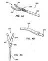
- blades or tips 212, 214include pins 218, 216, rather than slots, much area is not needed on the back ends. This is beneficial because the "wingspan" of the blades or tips 212, 214 when opened is minimized if not eliminated. In addition, the overall strength of the blades or tips 212, 214 and the rod 224 is maximized because both the rod and the blades are integral or are single piece components.
- FIG. 5there is shown a perspective view of the tool mechanism 210 of FIG. 4 being connected to the actuation rod 224.
- the blades or tips 212, 214can be formed from conventional stamping and then heat treated.
- the blades or tips 212, 214can be formed from a blank of pre-hardened material and then EDM cut, waterjet cut, laser cut or even machined to obtain the final shape.
- pins 218, 216 in the back ends of the blades or tips 212, 214can be formed directly onto the blades or pins themselves, or they can be added after the pins have been manufactured.
- the slots or channels 226can be of any of the above-described design, however, the actuation rod is split into a plurality of multiple pieces 224c, 224d to provide independent motion to the blades or tips. This would be useful if the blades or tips need to be articulated at different speeds, or over different distances.
Landscapes
- Health & Medical Sciences (AREA)
- Surgery (AREA)
- Life Sciences & Earth Sciences (AREA)
- Medical Informatics (AREA)
- Animal Behavior & Ethology (AREA)
- Engineering & Computer Science (AREA)
- Biomedical Technology (AREA)
- Heart & Thoracic Surgery (AREA)
- Veterinary Medicine (AREA)
- Molecular Biology (AREA)
- Nuclear Medicine, Radiotherapy & Molecular Imaging (AREA)
- General Health & Medical Sciences (AREA)
- Public Health (AREA)
- Orthopedic Medicine & Surgery (AREA)
- Pathology (AREA)
- Dentistry (AREA)
- Oral & Maxillofacial Surgery (AREA)
- Ophthalmology & Optometry (AREA)
- Surgical Instruments (AREA)
Description
- This invention generally relates to laparoscopic surgical instruments and, in particular, to a system for actuating the tips of a laparoscopic surgical instrument.
- Laparoscopic surgical instruments or devices that use actuating blades or tips are typically activated by some mechanical means. In most cases, the surgical instruments or devices use an actuation rod to translate motion from a handle at one end to a tip at the opposite end of the device. Common to laparoscopic scissors and graspers is an actuation rod that includes a pin that works in conjunction with a slot in the tips. Moving the actuation rod cams the pin in the slot which opens and closes the tips.
- The blades or tips typically have slots proximal to the pivot and because of this configuration, the back end of the blades or tips need to be quite large. When used on a grasper and the tips are in their open position, the back end of the tips extend out beyond the outside diameter of the grasper shaft and look like "wings." This may be a problem for the user and, in particular, the patient as they can catch or interfere on tissue or other devices during use.
- When used on scissors, these wings will most likely be covered up with a plastic shrink tubing to insulate all the metal components during electro-surgical cautery. However, when the blades or tips are open, the wings can stretch and deform the shrink tubing. This can be problematic in that when the scissors is withdrawn from the trocar, the deformed tubing may not relax and it may catch on the end of the cannula, thereby pulling the trocar out of the patient. Accordingly, there is a need in the art for an improved system and method for actuating the blades or tips of laparoscopic instruments so as to minimize the adverse wing effect.
DE 20001492U discloses a laparoscopic surgical instrument according to the preamble of claim 1.- According to the present invention there is provided a surgical instrument, comprising: an elongate tube extending along an axis including an actuation rod coaxially slidable within the elongate tube; a first tip including, a first pin formed on a proximal end surface of the first tip; and a second tip including a second pin formed on a proximal end surface of the second tip, the second tip pivotally connected to the first tip at a common pivot pin operably connected to the elongate tube to open and close the tips in response to movement of the actuation rod, the actuation rod having a slot to accept the pins of the first and second tips, the slot having camming surfaces for the pins to slide within the slot, and the proximal ends of the tips extend minimally outside the diameter of the elongate tube during actuation of the tips, characterized in that, wherein the actuation rod is a tongue actuation rod which includes two transverse slots on opposing sides of the tongue and means for ratcheting the tips into a desired position.
- The invention enables the back end of each blade or tip to be dramatically reduced in area so that during full defection, very little or no part of the blade or tip extends beyond the outside diameter of the outer tube or shaft. This ensures that nothing catches on the blades or tips during grasper use and the shrink tubing found on the scissors would not be deformed. This can be done because the area for the slots is not needed. Moreover, the usable area for the drive slots on the blade or tip of the actuation rod is maximized to the overall diameter of the outer tube or shaft which provides additional leverage to the blades or tips. In addition, the depth of the slot can be varied such that increased tension can be placed on the blades or tips during actuation.
- The ratcheting means may include a series of detents.
- These and other features and advantages of the invention will become more apparent with a discussion of the embodiments in reference to the associated drawings.
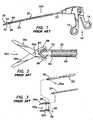
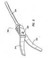
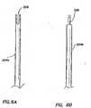
FIG. 1 illustrates a perspective view of a laparoscopic view of a surgical instrument of the prior art;FIG. 2 illustrates a side cutaway view of a tool mechanism of the surgical instrument ofFIG. 1 in the open position;FIG. 3 is an exploded perspective view ofFIG. 2 ;FIGS. 4(a) - 4(c) illustrate a perspective view of a laparoscopic surgical instrument to which the invention may be applied, a perspective view of a blade or tip of the tool mechanism, and a side view ofFIG. 4(a) , respectively;FIG. 5 illustrates a perspective view of an assembled surgical instrument to which the invention may be applied having mobile tips and an actuation rod;FIGS. 6(a) and 6(b) illustrate a fork actuation rod and a tongue actuation rod, respectively;FIGS. 7(a) and 7(b) illustrate a perspective view and a side view of the fork actuation rod, not in accordance with the present invention, having slots on both sides of the fork end;FIGS. 7(c) and 7(d) illustrate a perspective view and a side view of an actuation rod having a slot with an open end;FIGS. 7(e) and 7(f) illustrate a perspective view and a side view of an actuation rod having a curved slot;FIGS. 8(a) and 8(b) illustrate a side view and a cross-section view of an actuation rod having an angled slot;FIG. 8(c) illustrates a slot in an actuation rod having a detent or elevation shift to temporarily lock or ratchet the tips into a desired position in accordance with the invention;FIG. 8(d) illustrates a slot in an actuation rod having a locking mechanism;FIG. 9 illustrates a perspective view of an assembled surgical instrument having a fixed tip and a mobile tip; andFIG. 10 illustrates an actuation rod that is split into at least two pieces to provide independent motion to the tips.- Referring to
FIG. 1 , there is shown a perspective view of a laparoscopicsurgical instrument 100 of the prior art as shown inU.S. Patent No. 5,626,609 . Thesurgical instrument 100 typically comprises ahandle assembly 10 having afixed handle 12 and apivoting handle 14. Extending from thehandle assembly 10 is ashaft assembly 20 comprising anouter tube 22 and aninner actuation rod 24. Theactuation rod 24 slides in theouter tube 20 in a coaxial relationship. Theouter tube 22 may be secured to thefixed handle 12, while theactuation rod 24 may be secured to thepivoting handle 14. Attached at a distal end of theshaft assembly 20 is atool mechanism 30, which comprises of alower jaw 32 and anupper jaw 34. Thetool mechanism 30 is connected to theshaft assembly 20 atpivot point 36 throughlinkage mechanism 40. During use, as theactuation rod 24 slides within theouter tube 22, thelinkage mechanism 40 is actuated topivot jaws pivot point 36 to open and close the jaws. - Referring to
FIGS. 2 and 3 , there is shown atool mechanism 30a of the prior art which includes, for example, afirst scissor blade 32a and asecond scissor blade 34a. In this embodiment, ahousing member 50 is attached to theouter tube 22, and thetool mechanism 30a is attached to thehousing member 50. As the handles move, theactuation rod 24 slides through theouter tube 22 towards thetool mechanism 30a. As illustrated inFIG. 2 ,scissor blades cam slots bearing post 60 which is attached toinner rod 24. As therod 24 moves, thebearing post 60 slides withincam slots blades pivot pin 36a to open and close the blades. A drawback of thistool mechanism 30a is when theblades slot 70 inhousing member 50 to allow the blades to open. That is, the tail end of theblades blades shaft assembly 20. For example, this can be problematic in that when the instrument is withdrawn from a trocar after a procedure, the deformed tubing may not relax and it may catch on the end of the cannula, whereby pulling the trocar out of the patient. - Referring to
FIGS. 4(a) - 4(c) , there is shown asurgical instrument 200 in having atool mechanism 210 including a first blade ortip 212 and a second blade ortip 214, each of which has apin 218 and 216, respectively, formed at the proximal end. Thepins 218, 216 are fixed, typically by welding, to blades ortips tips tips common pin 220. It includes thetool mechanism 210 that interacts with a slottedactuation rod 224 as further explained below. It is appreciated that because the blades ortips pins 218, 216, rather than slots, much area is not needed on the back ends. This is beneficial because the "wingspan" of the blades ortips tips rod 224 is maximized because both the rod and the blades are integral or are single piece components. - The
fork actuation rod 224 can be formed in a number of different ways. For example, the desired features can be machined from a solid rod or tube of a desired diameter. In another aspect, a strip of metal can be stamped with the desired slots at the end, then the tube can be rolled into a particular diameter where the slotted end can form a "fork". In yet another aspect, the fork features at the end of the actuation rod can be overmolded onto a shaft to provide a cost effective component. - As to the tongue actuation rod, it can be formed in a similar way to the fork actuation rod. More specifically, machining the detail in the tip is an option as is overmolding the detail. The end of the actuation rod can also be formed as a separate part, i.e., molded, machined, cast, MIM, etc., with the feature detail in it and then attached to a standard length shaft by means of a thread, snap, adhesive, welding process or some other attachment method.
- Referring to
FIG. 5 , there is shown a perspective view of thetool mechanism 210 ofFIG. 4 being connected to theactuation rod 224. It is appreciated that there are numerous methods of manufacturing the blades ortips tips tips pins 218, 216 in the back ends of the blades ortips - The
pins 218, 216 can be locked in any one or a combination of the following ways: press-fitted, swaged, threaded and/or welded. To manufacture the pin as part of the blades ortips - There are also additional processes that can yield the entire part from a minimum number of operations. These can include but are not limited to metal injection molding (MIM), casting, and powder metallurgy (PM). The final blade can also then be sent to be sharpened or other post processing.
- The following is a discussion of the pin and slot design, where there are a number of advantages which can be realized. For example,
- (1) The back end of each blade or tip is reduced in area so that during full deflection, very little or no part of the blade or tip extends beyond the outside diameter of the outer tube or shaft. This ensures that nothing catches on the blades or tips during grasper use and the shrink tubing found on scissors would not be deformed. This can be done because the area for the slots is not needed;
- (2) The usable area for the drive slots on the blade or tip of the actuation rod is maximized to the overall diameter of the outer tube or shaft which provides additional leverage to the blades or tips; and
- (3) If channels are used on the actuation rod, the depth of the channels can be varied such that increased tension can be placed on the blades during actuation.
- Moreover, by moving the slot from the blades or tips to the actuation rod, the "wingspan" of the blades can be reduced or eliminated because the back end does not need to endcase the slot, but rather a small pin which minimizes the chance of catching on tissue, other instruments or suture.
- Referring to
FIGS. 6(a) and 6(b) , there are shown the end of the actuation rod which could be afork design 224a or (in accordance with the present invention) atongue design 224b. With thefork design 224a, a throughslot 226 can be formed on each side of therod 224a. The back end of the blades or tips can be inserted into the rod where the pin of the first blade or tip can be locked into the first slot and the pin of the second blade or tip can be locked into the opposing second slot. The blades or tips can be fixed by a common pivot point on the outer tube or shaft. When the actuation rod is moved in one direction, the blades or tips will cam via the pins and theslots 226. The pin that locks each blade or tip into the shaft can be integral to the blades or tips or they can be separate components. Similarly to thefork design 224a, thetongue design 224b can include aslot 226 on each side of the tongue as further discussed below. - Referring to
FIGS. 7(a) and 7(b) , there are shown a perspective view and a side view of theactuation rod 224 incorporatingslots 226 on both sides of the fork end, respectively. As explained above, the blades or tips can have pins on the back end that nest in the slots of the rod. The rod may be pushed forward or pulled backwards to cam the blades or tips, which are pivoted by a common pivot point that is attached to the outer tube or shaft. In some cases, it is beneficial to have different slot designs to actuate the tips to different openings, at different speeds, for different length tips and for varying force. Referring toFIGS. 7(c) and 7(d) , theslots 226 can include an open or closed end slot (or combination of both) as desired.FIGS. 7(e) and 7(f) illustrate an actuation rod having a curved slot. It is appreciated that as the jaw providing the blades or tips of the invention articulates a pivot point, the distance between the pin and slot and the hinge vary depending on the actuation rod position. Accordingly, the curved slot can be used to compensate for this phenomenon and provide for a more linear relation between the actuation rod and the jaw motion. For example, the slot can be shaped to provide for more control as the blades or tips are nearing the closed position, and greater acceleration as the blades or tips are near the opened position. With this aspect, the instrument can be tuned to provide the desired instrument control and user feedback. - As illustrated in
FIGS. 8(a) and 8(b) , a slot 226b for the tongue can be formed such that it has an angle to it. In other words, the depth of the slot 226b at one end ('B') 227 may be deeper or shallower than at the other end ('A') 228. This is beneficial because as theactuation rod 224 is pulled, and the blades or tips close, the pins camming in the slots can be forced apart by the angle at the bottom surface of the slots. This would spread the back end of the blades or tips which in turn push the front of the blades or tips together putting more tension along the cutting surface. - In
FIG. 8(c) , there is illustrated the embodiment in accordance with the present invention, where aslot 226 has a detent orelevation shift 229 to temporarily "lock" or "ratchet" the blade or tip into a desired position without affecting the linear motion of the jaws relative to the handle actuation.FIG. 8(d) illustrates that aslot 226 can also be formed with different cross sections, e.g., slot 226 having a locking mechanism with adovetail profile 230. With this embodiment, the mating pin on the blades or tips can match the slot to "lock" it in. - As illustrated in
FIG. 9 , both blades ortips blade 212 may be fixed while theother blade 214 may actuate. Themobile blade 214 may contain apin 300 and anactuation rod 302 that would contain only one slot to actuate theblade 214. - Referring to
FIG. 10 , the slots orchannels 226 can be of any of the above-described design, however, the actuation rod is split into a plurality ofmultiple pieces - It will be understood that many other modifications can be made to the various disclosed embodiments without departing from the scope of the invention as defined by the appended claims. For these reasons, the above description should not be construed as limiting the invention, but should be interpreted as merely exemplary of preferred embodiments.
Claims (10)
- A surgical instrument (200), comprising:an elongate tube extending along an axis including an actuation rod (224) coaxially slidable within the elongate tube;a first tip (212) including a first pin formed on a proximal end surface of the first tip; anda second tip (214) including a second pin (216) formed on a proximal end surface of the second tip, the second tip pivotally connected to the first tip at a common pivot pin (220) operably connected to the elongate tube to open and chose the tips in response to movement of the actuation rod (224),the actuation rod having a slot (226) to accept the pins of the first and second tips, the slot having camming surfaces for the pins to slide within the slot, and the proximal ends of the tips extend minimally outside the diameter of the elongate tube during actuation of the tips, whereinthe actuation rod (224) is a tongue actuation rod which includes two transverse slots (226) on opposing sides of the tongue andcharacterized in that said transverse slots (226) having a detent or elevation shift 229 to temporarily lock or ratchet the tips into a desired position.
- The surgical instrument of claim 1, wherein the proximal ends of the tips (212, 214) do not extend outside the diameter of the elongate tube during actuation of the tips.
- The surgical instrument of claim 1, wherein the actuation rod (224) is formed by machining, stamping, overmolding, casting, or metal injection molding.
- The surgical instrument of claim 1, wherein the tongue actuation rod includes a through slot on each side of the rod.
- The surgical instrument of claim 4, wherein the slots (226) are curved.
- The surgical instrument of claim 1, wherein the slots (226) are curved.
- The surgical instrument of claim 1 or claim 4, wherein at least one of the slots (226) is an open-end slot or a closed end slot.
- the surgical instrument of claim 1, wherein the ratcheting means includes a series of detents (229).
- The surgical instrument of claim 1, wherein the pins are formed on the proximal end surfaces of the tips by press fitting, threading, welding or bonding.
- The surgical instrument of any preceding claim, wherein the proximal ends of the tips do not extend outside the diameter of the elongate tube during actuation of the tips.
Applications Claiming Priority (2)
| Application Number | Priority Date | Filing Date | Title |
|---|---|---|---|
| US54874704P | 2004-02-27 | 2004-02-27 | |
| EP05713752AEP1718224B1 (en) | 2004-02-27 | 2005-02-17 | System for actuating a laparoscopic surgical instrument |
Related Parent Applications (2)
| Application Number | Title | Priority Date | Filing Date |
|---|---|---|---|
| EP05713752ADivisionEP1718224B1 (en) | 2004-02-27 | 2005-02-17 | System for actuating a laparoscopic surgical instrument |
| EP05713752.3Division | 2005-02-17 |
Publications (2)
| Publication Number | Publication Date |
|---|---|
| EP2022417A1 EP2022417A1 (en) | 2009-02-11 |
| EP2022417B1true EP2022417B1 (en) | 2010-04-07 |
Family
ID=34960959
Family Applications (2)
| Application Number | Title | Priority Date | Filing Date |
|---|---|---|---|
| EP08170110ACeasedEP2022417B1 (en) | 2004-02-27 | 2005-02-17 | System for actuating a laparoscopic surgical instrument |
| EP05713752ACeasedEP1718224B1 (en) | 2004-02-27 | 2005-02-17 | System for actuating a laparoscopic surgical instrument |
Family Applications After (1)
| Application Number | Title | Priority Date | Filing Date |
|---|---|---|---|
| EP05713752ACeasedEP1718224B1 (en) | 2004-02-27 | 2005-02-17 | System for actuating a laparoscopic surgical instrument |
Country Status (5)
| Country | Link |
|---|---|
| US (2) | US7578832B2 (en) |
| EP (2) | EP2022417B1 (en) |
| JP (1) | JP2007525285A (en) |
| DE (2) | DE602005020534D1 (en) |
| WO (1) | WO2005092216A1 (en) |
Families Citing this family (129)
| Publication number | Priority date | Publication date | Assignee | Title |
|---|---|---|---|---|
| US7559893B2 (en) | 1998-12-01 | 2009-07-14 | Atropos Limited | Wound retractor device |
| US6254534B1 (en) | 1999-10-14 | 2001-07-03 | Atropos Limited | Retractor |
| US7998068B2 (en) | 1998-12-01 | 2011-08-16 | Atropos Limited | Instrument access device |
| US7537564B2 (en) | 1998-12-01 | 2009-05-26 | Atropos Limited | Wound retractor device |
| CN100512766C (en) | 1998-12-01 | 2009-07-15 | 阿特波斯有限公司 | A surgical device for retracting and/or sealing an incision |
| US7540839B2 (en) | 1999-10-14 | 2009-06-02 | Atropos Limited | Wound retractor |
| JP5190169B2 (en) | 2000-10-19 | 2013-04-24 | アプライド メディカル リソーシーズ コーポレイション | Surgical access instruments and methods |
| EP2422829B1 (en) | 2001-08-14 | 2013-03-06 | Applied Medical Resources Corporation | Surgical access sealing apparatus |
| US6958037B2 (en) | 2001-10-20 | 2005-10-25 | Applied Medical Resources Corporation | Wound retraction apparatus and method |
| EP2343032B1 (en) | 2002-06-05 | 2012-05-09 | Applied Medical Resources Corporation | Wound retractor |
| US9271753B2 (en) | 2002-08-08 | 2016-03-01 | Atropos Limited | Surgical device |
| DE60314464T2 (en) | 2002-09-19 | 2008-02-14 | Atropos Ltd., Bray | SURGICAL WOUND RETRACTOR |
| US20050020884A1 (en) | 2003-02-25 | 2005-01-27 | Hart Charles C. | Surgical access system |
| US7468041B2 (en)* | 2003-06-26 | 2008-12-23 | Depuy Products, Inc. | Modular surgical instrument with reciprocable implement |
| CA2533204A1 (en) | 2003-08-06 | 2005-02-17 | Applied Medical Resources Corporation | Surgical device with tack-free gel and method of manufacture |
| US7163510B2 (en) | 2003-09-17 | 2007-01-16 | Applied Medical Resources Corporation | Surgical instrument access device |
| US8114107B2 (en)* | 2003-11-05 | 2012-02-14 | Applied Medical Resources Corporation | Laparoscopic scissor blades |
| JP2009501045A (en) | 2005-07-15 | 2009-01-15 | アトロポス・リミテッド | Wound retractor |
| AU2006304141B2 (en) | 2005-10-14 | 2012-07-05 | Applied Medical Resources Corporation | Gel cap for wound retractor |
| US7655004B2 (en) | 2007-02-15 | 2010-02-02 | Ethicon Endo-Surgery, Inc. | Electroporation ablation apparatus, system, and method |
| US7815662B2 (en) | 2007-03-08 | 2010-10-19 | Ethicon Endo-Surgery, Inc. | Surgical suture anchors and deployment device |
| US8075572B2 (en) | 2007-04-26 | 2011-12-13 | Ethicon Endo-Surgery, Inc. | Surgical suturing apparatus |
| US8100922B2 (en) | 2007-04-27 | 2012-01-24 | Ethicon Endo-Surgery, Inc. | Curved needle suturing tool |
| EP2146644A4 (en) | 2007-05-11 | 2012-07-18 | Applied Med Resources | Surgical retractor |
| WO2008141291A1 (en) | 2007-05-11 | 2008-11-20 | Applied Medical Resources Corporation | Surgical retractor with gel pad |
| WO2008149332A1 (en) | 2007-06-05 | 2008-12-11 | Atropos Limited | An instrument access device |
| US8657740B2 (en) | 2007-06-05 | 2014-02-25 | Atropos Limited | Instrument access device |
| US8579897B2 (en) | 2007-11-21 | 2013-11-12 | Ethicon Endo-Surgery, Inc. | Bipolar forceps |
| US8262655B2 (en) | 2007-11-21 | 2012-09-11 | Ethicon Endo-Surgery, Inc. | Bipolar forceps |
| US8568410B2 (en) | 2007-08-31 | 2013-10-29 | Ethicon Endo-Surgery, Inc. | Electrical ablation surgical instruments |
| US20090112059A1 (en) | 2007-10-31 | 2009-04-30 | Nobis Rudolph H | Apparatus and methods for closing a gastrotomy |
| US8480657B2 (en) | 2007-10-31 | 2013-07-09 | Ethicon Endo-Surgery, Inc. | Detachable distal overtube section and methods for forming a sealable opening in the wall of an organ |
| CA2711116C (en) | 2008-01-22 | 2017-08-29 | Applied Medical Resources Corporation | Surgical instrument access device |
| US8262680B2 (en) | 2008-03-10 | 2012-09-11 | Ethicon Endo-Surgery, Inc. | Anastomotic device |
| US8277475B2 (en) | 2008-05-09 | 2012-10-02 | Applied Medical Resources Corporation | Laparoscopic scissors |
| US8652150B2 (en) | 2008-05-30 | 2014-02-18 | Ethicon Endo-Surgery, Inc. | Multifunction surgical device |
| US8317806B2 (en) | 2008-05-30 | 2012-11-27 | Ethicon Endo-Surgery, Inc. | Endoscopic suturing tension controlling and indication devices |
| US8070759B2 (en) | 2008-05-30 | 2011-12-06 | Ethicon Endo-Surgery, Inc. | Surgical fastening device |
| US8679003B2 (en) | 2008-05-30 | 2014-03-25 | Ethicon Endo-Surgery, Inc. | Surgical device and endoscope including same |
| US8771260B2 (en) | 2008-05-30 | 2014-07-08 | Ethicon Endo-Surgery, Inc. | Actuating and articulating surgical device |
| US8114072B2 (en) | 2008-05-30 | 2012-02-14 | Ethicon Endo-Surgery, Inc. | Electrical ablation device |
| US8906035B2 (en) | 2008-06-04 | 2014-12-09 | Ethicon Endo-Surgery, Inc. | Endoscopic drop off bag |
| US8403926B2 (en) | 2008-06-05 | 2013-03-26 | Ethicon Endo-Surgery, Inc. | Manually articulating devices |
| US8361112B2 (en) | 2008-06-27 | 2013-01-29 | Ethicon Endo-Surgery, Inc. | Surgical suture arrangement |
| US8888792B2 (en) | 2008-07-14 | 2014-11-18 | Ethicon Endo-Surgery, Inc. | Tissue apposition clip application devices and methods |
| US8262563B2 (en) | 2008-07-14 | 2012-09-11 | Ethicon Endo-Surgery, Inc. | Endoscopic translumenal articulatable steerable overtube |
| US8211125B2 (en) | 2008-08-15 | 2012-07-03 | Ethicon Endo-Surgery, Inc. | Sterile appliance delivery device for endoscopic procedures |
| US8529563B2 (en) | 2008-08-25 | 2013-09-10 | Ethicon Endo-Surgery, Inc. | Electrical ablation devices |
| US8241204B2 (en) | 2008-08-29 | 2012-08-14 | Ethicon Endo-Surgery, Inc. | Articulating end cap |
| US8480689B2 (en) | 2008-09-02 | 2013-07-09 | Ethicon Endo-Surgery, Inc. | Suturing device |
| US8409200B2 (en) | 2008-09-03 | 2013-04-02 | Ethicon Endo-Surgery, Inc. | Surgical grasping device |
| US8114119B2 (en) | 2008-09-09 | 2012-02-14 | Ethicon Endo-Surgery, Inc. | Surgical grasping device |
| US8337394B2 (en) | 2008-10-01 | 2012-12-25 | Ethicon Endo-Surgery, Inc. | Overtube with expandable tip |
| CA2739910C (en) | 2008-10-13 | 2017-06-06 | Applied Medical Resources Corporation | Single port access system |
| US8157834B2 (en) | 2008-11-25 | 2012-04-17 | Ethicon Endo-Surgery, Inc. | Rotational coupling device for surgical instrument with flexible actuators |
| US8172772B2 (en) | 2008-12-11 | 2012-05-08 | Ethicon Endo-Surgery, Inc. | Specimen retrieval device |
| US8361066B2 (en) | 2009-01-12 | 2013-01-29 | Ethicon Endo-Surgery, Inc. | Electrical ablation devices |
| US8828031B2 (en) | 2009-01-12 | 2014-09-09 | Ethicon Endo-Surgery, Inc. | Apparatus for forming an anastomosis |
| US9226772B2 (en) | 2009-01-30 | 2016-01-05 | Ethicon Endo-Surgery, Inc. | Surgical device |
| US8252057B2 (en) | 2009-01-30 | 2012-08-28 | Ethicon Endo-Surgery, Inc. | Surgical access device |
| US8037591B2 (en) | 2009-02-02 | 2011-10-18 | Ethicon Endo-Surgery, Inc. | Surgical scissors |
| US8375955B2 (en) | 2009-02-06 | 2013-02-19 | Atropos Limited | Surgical procedure |
| US20100298853A1 (en)* | 2009-05-22 | 2010-11-25 | Slater Charles R | Endoscopic Instrument Having Rotatably Mounted End Effector Assembly |
| US8690909B2 (en)* | 2009-05-22 | 2014-04-08 | Charles R. Slater | Endoscopic instrument with bi-laterally widened cam-slot at end effector |
| US20100298854A1 (en)* | 2009-05-22 | 2010-11-25 | Slater Charles R | Endoscopic Instrument with Control Member Having Decreasing Torsional and Flexural Stiffness Along Its Length |
| US9277932B2 (en)* | 2009-05-22 | 2016-03-08 | Slatr Surgical Holdings Llc | Endoscopic scissors instrument with friction enhancing tissue stops |
| US9566082B2 (en)* | 2009-05-22 | 2017-02-14 | Slatr Surgical Holdings Llc | Endoscopic instrument |
| BRPI1012156A2 (en)* | 2009-05-22 | 2016-04-05 | Apollo Endosurgery Inc | endoscopic instrument. |
| US20110029010A1 (en)* | 2009-07-28 | 2011-02-03 | Salvatore Castro | Flexible dissecting forceps |
| WO2011033495A1 (en) | 2009-09-17 | 2011-03-24 | Atropos Limited | An instrument access device |
| US20110098704A1 (en) | 2009-10-28 | 2011-04-28 | Ethicon Endo-Surgery, Inc. | Electrical ablation devices |
| US8608652B2 (en) | 2009-11-05 | 2013-12-17 | Ethicon Endo-Surgery, Inc. | Vaginal entry surgical devices, kit, system, and method |
| US8496574B2 (en) | 2009-12-17 | 2013-07-30 | Ethicon Endo-Surgery, Inc. | Selectively positionable camera for surgical guide tube assembly |
| US8353487B2 (en) | 2009-12-17 | 2013-01-15 | Ethicon Endo-Surgery, Inc. | User interface support devices for endoscopic surgical instruments |
| US9028483B2 (en) | 2009-12-18 | 2015-05-12 | Ethicon Endo-Surgery, Inc. | Surgical instrument comprising an electrode |
| US8506564B2 (en) | 2009-12-18 | 2013-08-13 | Ethicon Endo-Surgery, Inc. | Surgical instrument comprising an electrode |
| US9005198B2 (en) | 2010-01-29 | 2015-04-14 | Ethicon Endo-Surgery, Inc. | Surgical instrument comprising an electrode |
| US9339341B2 (en)* | 2010-02-08 | 2016-05-17 | Intuitive Surgical Operations, Inc. | Direct pull surgical gripper |
| USD648434S1 (en)* | 2010-05-07 | 2011-11-08 | Karl Storz Gmbh & Co. Kg | Forceps inserts for laparoscopic Procedures |
| USD641873S1 (en)* | 2010-06-09 | 2011-07-19 | Karl Storz Gmbh & Co. Kg | Forceps for transanal videoendoscopic rectal surgery |
| USD641872S1 (en)* | 2010-06-09 | 2011-07-19 | Karl Storz Gmbh & Co. Kg | Forceps for transanal videoendoscopic rectal surgery |
| USD641874S1 (en)* | 2010-06-09 | 2011-07-19 | Karl Storz Gmbh & Co. Kg | Forceps for transanal videoendoscopic rectal surgery |
| JP5704858B2 (en)* | 2010-08-24 | 2015-04-22 | Hoya株式会社 | Endoscopy forceps |
| US8523893B2 (en) | 2010-09-30 | 2013-09-03 | Applied Medical Resources Corporation | Laparoscopic scissors |
| US9289115B2 (en) | 2010-10-01 | 2016-03-22 | Applied Medical Resources Corporation | Natural orifice surgery system |
| JP6396657B2 (en) | 2010-10-01 | 2018-09-26 | アプライド メディカル リソーシーズ コーポレイション | Natural orifice surgery system |
| US10092291B2 (en) | 2011-01-25 | 2018-10-09 | Ethicon Endo-Surgery, Inc. | Surgical instrument with selectively rigidizable features |
| US9254169B2 (en) | 2011-02-28 | 2016-02-09 | Ethicon Endo-Surgery, Inc. | Electrical ablation devices and methods |
| US9233241B2 (en) | 2011-02-28 | 2016-01-12 | Ethicon Endo-Surgery, Inc. | Electrical ablation devices and methods |
| US9314620B2 (en) | 2011-02-28 | 2016-04-19 | Ethicon Endo-Surgery, Inc. | Electrical ablation devices and methods |
| US9049987B2 (en) | 2011-03-17 | 2015-06-09 | Ethicon Endo-Surgery, Inc. | Hand held surgical device for manipulating an internal magnet assembly within a patient |
| US8758236B2 (en) | 2011-05-10 | 2014-06-24 | Applied Medical Resources Corporation | Wound retractor |
| EP2522280B1 (en) | 2011-05-11 | 2016-03-02 | University Of Dundee | Medical instrument for grasping an object, in particular a needle holder |
| US9089357B2 (en)* | 2011-07-11 | 2015-07-28 | Herbert D. Huddleston | Multi-functional double bladed surgical tool |
| WO2013039860A1 (en)* | 2011-09-13 | 2013-03-21 | Interplex Industries, Inc. | Single piece biopsy forceps |
| US9636169B2 (en)* | 2011-09-19 | 2017-05-02 | Covidien Lp | Electrosurgical instrument |
| US8986199B2 (en) | 2012-02-17 | 2015-03-24 | Ethicon Endo-Surgery, Inc. | Apparatus and methods for cleaning the lens of an endoscope |
| US20150327751A1 (en)* | 2012-04-25 | 2015-11-19 | Industry-University Cooperation Foundation Hanyang University Erica Campus | Bendable end-effector |
| US9427255B2 (en) | 2012-05-14 | 2016-08-30 | Ethicon Endo-Surgery, Inc. | Apparatus for introducing a steerable camera assembly into a patient |
| US9078662B2 (en) | 2012-07-03 | 2015-07-14 | Ethicon Endo-Surgery, Inc. | Endoscopic cap electrode and method for using the same |
| WO2014008492A1 (en)* | 2012-07-06 | 2014-01-09 | Intuitive Surgical Operations, Inc. | Remotely actuated surgical gripper with seize resistance |
| US9545290B2 (en) | 2012-07-30 | 2017-01-17 | Ethicon Endo-Surgery, Inc. | Needle probe guide |
| US10314649B2 (en) | 2012-08-02 | 2019-06-11 | Ethicon Endo-Surgery, Inc. | Flexible expandable electrode and method of intraluminal delivery of pulsed power |
| US9572623B2 (en) | 2012-08-02 | 2017-02-21 | Ethicon Endo-Surgery, Inc. | Reusable electrode and disposable sheath |
| US9277957B2 (en) | 2012-08-15 | 2016-03-08 | Ethicon Endo-Surgery, Inc. | Electrosurgical devices and methods |
| US10098527B2 (en) | 2013-02-27 | 2018-10-16 | Ethidcon Endo-Surgery, Inc. | System for performing a minimally invasive surgical procedure |
| US20140257416A1 (en)* | 2013-03-06 | 2014-09-11 | Nathan Meyer | Percutaneous rod inserter |
| JP2016512725A (en) | 2013-03-15 | 2016-05-09 | アプライド メディカル リソーシーズ コーポレイション | Mechanical gel surgical access instrument |
| WO2014172676A1 (en)* | 2013-04-20 | 2014-10-23 | Apollo Endosurgery, Inc. | Flexible endoscopic torqueable devices |
| CN103445858B (en)* | 2013-09-13 | 2015-09-16 | 安徽奥弗医疗设备科技股份有限公司 | A kind of heat setting cutter |
| CN103445862B (en)* | 2013-09-13 | 2015-11-11 | 安徽奥弗医疗设备科技股份有限公司 | A kind of connecting device of heat setting cutter gripper jaw |
| EP3169510B1 (en) | 2014-07-18 | 2018-10-03 | Applied Medical Resources Corporation | Method for manufacturing gels having permanent tack free coatings |
| KR20240172766A (en) | 2014-08-15 | 2024-12-10 | 어플라이드 메디컬 리소시스 코포레이션 | Natural orifice surgery system |
| USD761961S1 (en) | 2014-11-07 | 2016-07-19 | Karl Storz Gmbh & Co. Kg | Forceps insert for laparoscopic procedures |
| WO2016085930A2 (en) | 2014-11-25 | 2016-06-02 | Applied Medical Resources Corporation | Circumferential wound retraction with support and guidance structures |
| USD789535S1 (en) | 2015-06-17 | 2017-06-13 | Karl Storz Gmbh & Co. Kg | Shaft instrument for shaving tissue |
| USD791321S1 (en) | 2015-06-17 | 2017-07-04 | Karl Storz Gmbh & Co. Kg | Shaft instrument for shaving tissue |
| US10368908B2 (en) | 2015-09-15 | 2019-08-06 | Applied Medical Resources Corporation | Surgical robotic access system |
| WO2017062850A2 (en) | 2015-10-07 | 2017-04-13 | Applied Medical Resources Corporation | Wound retractor with multi-segment outer ring |
| AU2017324450B2 (en) | 2016-09-12 | 2022-09-29 | Applied Medical Resources Corporation | Surgical robotic access system for irregularly shaped robotic actuators and associated robotic surgical instruments |
| US10925628B2 (en)* | 2017-09-18 | 2021-02-23 | Novuson Surgical, Inc. | Tissue engagement apparatus for theapeutic ultrasound apparatus and method |
| US20190254644A1 (en)* | 2018-02-22 | 2019-08-22 | Boston Scientific Limited | Biopsy forceps with cam mechanism |
| US11612447B2 (en) | 2018-07-19 | 2023-03-28 | Intuitive Surgical Operations, Inc. | Medical devices having three tool members |
| US11103245B2 (en)* | 2018-12-31 | 2021-08-31 | Cilag Gmbh International | Knife for surgical stapler and associated method of manufacture with MIM and hip |
| CN110051425B (en)* | 2019-05-15 | 2023-11-14 | 成都五义医疗科技有限公司 | Improved slender shaft assembly and surgical instrument |
| CN113952025B (en)* | 2019-05-15 | 2023-05-26 | 成都五义医疗科技有限公司 | Slender shaft assembly comprising static tube assembly and movable rod assembly for minimally invasive surgery |
| US11191586B2 (en)* | 2019-07-02 | 2021-12-07 | Jamison Alexander | Removable tip for use with electrosurgical devices |
| EP4027897B1 (en) | 2020-02-03 | 2025-04-16 | Boston Scientific Limited | Biopsy forceps with tissue piercing member |
| DK181495B1 (en)* | 2021-05-10 | 2024-03-12 | Flexlogical Aps | End effector for minimally invasive surgery |
Family Cites Families (19)
| Publication number | Priority date | Publication date | Assignee | Title |
|---|---|---|---|---|
| US5219357A (en)* | 1990-05-31 | 1993-06-15 | Tnco, Inc. | Micro-instrument |
| US5626609A (en) | 1990-10-05 | 1997-05-06 | United States Surgical Corporation | Endoscopic surgical instrument |
| US5176699A (en)* | 1991-06-05 | 1993-01-05 | Harold Markham | Surgical device with double jaw actuation |
| US5383888A (en)* | 1992-02-12 | 1995-01-24 | United States Surgical Corporation | Articulating endoscopic surgical apparatus |
| CA2079038A1 (en)* | 1991-10-18 | 1993-04-19 | Matthew Mudry | Endoscopic surgical instrument |
| US5281220A (en)* | 1992-01-13 | 1994-01-25 | Blake Joseph W Iii | Endoscopic instrument |
| US5275615A (en)* | 1992-09-11 | 1994-01-04 | Anthony Rose | Medical instrument having gripping jaws |
| US5496347A (en)* | 1993-03-30 | 1996-03-05 | Olympus Optical Co., Ltd. | Surgical instrument |
| GB9309142D0 (en)* | 1993-05-04 | 1993-06-16 | Gyrus Medical Ltd | Laparoscopic instrument |
| DE69530642T2 (en)* | 1994-07-29 | 2004-04-01 | Olympus Optical Co., Ltd. | Medical instrument for use in combination with endoscopes |
| CA2157744C (en)* | 1994-10-07 | 2005-08-23 | Charles R. Sherts | Endoscopic vascular suturing apparatus |
| DE19521257C2 (en)* | 1995-06-10 | 1999-01-28 | Winter & Ibe Olympus | Surgical forceps |
| US5893874A (en)* | 1997-02-07 | 1999-04-13 | Smith & Nephew, Inc. | Surgical instrument |
| US5810879A (en)* | 1997-02-27 | 1998-09-22 | Microline, Inc. | Laparoscopic instrument |
| US6228083B1 (en)* | 1997-11-14 | 2001-05-08 | Sherwood Services Ag | Laparoscopic bipolar electrosurgical instrument |
| DE20001492U1 (en)* | 2000-01-27 | 2000-06-21 | Aesculap AG & Co. KG, 78532 Tuttlingen | Surgical tubular shaft instrument |
| DE20121161U1 (en)* | 2001-01-31 | 2002-04-04 | Olympus Winter & Ibe Gmbh, 22045 Hamburg | Endoscopic instrument |
| WO2002064020A2 (en)* | 2001-02-13 | 2002-08-22 | Lumend, Inc. | Method and apparatus for micro-dissection of vascular occlusions |
| DE20309774U1 (en)* | 2003-06-20 | 2003-10-02 | Aesculap AG & Co. KG, 78532 Tuttlingen | Surgical instrument couple has a form/fit union with the power transmission link |
- 2005
- 2005-02-17EPEP08170110Apatent/EP2022417B1/ennot_activeCeased
- 2005-02-17DEDE602005020534Tpatent/DE602005020534D1/ennot_activeExpired - Lifetime
- 2005-02-17USUS11/059,806patent/US7578832B2/enactiveActive
- 2005-02-17WOPCT/US2005/005105patent/WO2005092216A1/enactiveApplication Filing
- 2005-02-17DEDE602005012482Tpatent/DE602005012482D1/ennot_activeExpired - Lifetime
- 2005-02-17JPJP2007500887Apatent/JP2007525285A/enactivePending
- 2005-02-17EPEP05713752Apatent/EP1718224B1/ennot_activeCeased
- 2009
- 2009-08-25USUS12/547,219patent/US8114120B2/ennot_activeExpired - Fee Related
Also Published As
| Publication number | Publication date |
|---|---|
| EP1718224A1 (en) | 2006-11-08 |
| JP2007525285A (en) | 2007-09-06 |
| US20050192598A1 (en) | 2005-09-01 |
| US7578832B2 (en) | 2009-08-25 |
| EP2022417A1 (en) | 2009-02-11 |
| DE602005020534D1 (en) | 2010-05-20 |
| DE602005012482D1 (en) | 2009-03-12 |
| US8114120B2 (en) | 2012-02-14 |
| EP1718224B1 (en) | 2009-01-21 |
| WO2005092216A1 (en) | 2005-10-06 |
| US20090318954A1 (en) | 2009-12-24 |
Similar Documents
| Publication | Publication Date | Title |
|---|---|---|
| EP2022417B1 (en) | System for actuating a laparoscopic surgical instrument | |
| US20060161190A1 (en) | Disposable laparoscopic instrument | |
| DE60109328T2 (en) | VESSEL SEALING DEVICE AND VACUUM CLEANER | |
| US5141517A (en) | Retractable instrument | |
| US6168605B1 (en) | Curved laparoscopic scissor having arcs of curvature | |
| US9161770B2 (en) | Overmolded grasper jaw | |
| US8568443B1 (en) | Surgical grapser tool and actuation mechanism | |
| US5707392A (en) | Hermaphroditic stamped forceps jaw for disposable endoscopic biopsy forceps and method of making the same | |
| US9179929B2 (en) | Laparoscopic scissors | |
| DE102017100311A1 (en) | Electrosurgical device | |
| US8523893B2 (en) | Laparoscopic scissors | |
| US20140005689A1 (en) | Suture cutter | |
| EP0778748A1 (en) | High velocity tissue sample cutter | |
| KR102724262B1 (en) | A soft tissue cutting tool having a self-locking, multi-position, and linearly actuated retractable blade or hook by a slide button. | |
| US20220151596A1 (en) | Locking Forceps | |
| EP4628027A2 (en) | Locking forceps | |
| DE102013005874A1 (en) | Handle for a surgical instrument | |
| DE202009009562U1 (en) | Surgical shift shaft instrument |
Legal Events
| Date | Code | Title | Description |
|---|---|---|---|
| PUAI | Public reference made under article 153(3) epc to a published international application that has entered the european phase | Free format text:ORIGINAL CODE: 0009012 | |
| 17P | Request for examination filed | Effective date:20081127 | |
| AC | Divisional application: reference to earlier application | Ref document number:1718224 Country of ref document:EP Kind code of ref document:P | |
| AK | Designated contracting states | Kind code of ref document:A1 Designated state(s):DE FR GB | |
| 17Q | First examination report despatched | Effective date:20090324 | |
| GRAP | Despatch of communication of intention to grant a patent | Free format text:ORIGINAL CODE: EPIDOSNIGR1 | |
| RTI1 | Title (correction) | Free format text:SYSTEM FOR ACTUATING A LAPAROSCOPIC SURGICAL INSTRUMENT | |
| RTI1 | Title (correction) | Free format text:SYSTEM FOR ACTUATING A LAPAROSCOPIC SURGICAL INSTRUMENT | |
| AKX | Designation fees paid | Designated state(s):DE FR GB | |
| GRAS | Grant fee paid | Free format text:ORIGINAL CODE: EPIDOSNIGR3 | |
| GRAA | (expected) grant | Free format text:ORIGINAL CODE: 0009210 | |
| AC | Divisional application: reference to earlier application | Ref document number:1718224 Country of ref document:EP Kind code of ref document:P | |
| AK | Designated contracting states | Kind code of ref document:B1 Designated state(s):DE FR GB | |
| REG | Reference to a national code | Ref country code:GB Ref legal event code:FG4D | |
| REF | Corresponds to: | Ref document number:602005020534 Country of ref document:DE Date of ref document:20100520 Kind code of ref document:P | |
| PLBE | No opposition filed within time limit | Free format text:ORIGINAL CODE: 0009261 | |
| STAA | Information on the status of an ep patent application or granted ep patent | Free format text:STATUS: NO OPPOSITION FILED WITHIN TIME LIMIT | |
| 26N | No opposition filed | Effective date:20110110 | |
| REG | Reference to a national code | Ref country code:FR Ref legal event code:PLFP Year of fee payment:12 | |
| REG | Reference to a national code | Ref country code:FR Ref legal event code:PLFP Year of fee payment:13 | |
| REG | Reference to a national code | Ref country code:FR Ref legal event code:PLFP Year of fee payment:14 | |
| PGFP | Annual fee paid to national office [announced via postgrant information from national office to epo] | Ref country code:FR Payment date:20230223 Year of fee payment:19 | |
| PGFP | Annual fee paid to national office [announced via postgrant information from national office to epo] | Ref country code:GB Payment date:20230227 Year of fee payment:19 Ref country code:DE Payment date:20230223 Year of fee payment:19 | |
| P01 | Opt-out of the competence of the unified patent court (upc) registered | Effective date:20230521 | |
| REG | Reference to a national code | Ref country code:DE Ref legal event code:R119 Ref document number:602005020534 Country of ref document:DE | |
| GBPC | Gb: european patent ceased through non-payment of renewal fee | Effective date:20240217 | |
| PG25 | Lapsed in a contracting state [announced via postgrant information from national office to epo] | Ref country code:DE Free format text:LAPSE BECAUSE OF NON-PAYMENT OF DUE FEES Effective date:20240903 | |
| PG25 | Lapsed in a contracting state [announced via postgrant information from national office to epo] | Ref country code:GB Free format text:LAPSE BECAUSE OF NON-PAYMENT OF DUE FEES Effective date:20240217 | |
| PG25 | Lapsed in a contracting state [announced via postgrant information from national office to epo] | Ref country code:FR Free format text:LAPSE BECAUSE OF NON-PAYMENT OF DUE FEES Effective date:20240229 | |
| PG25 | Lapsed in a contracting state [announced via postgrant information from national office to epo] | Ref country code:GB Free format text:LAPSE BECAUSE OF NON-PAYMENT OF DUE FEES Effective date:20240217 Ref country code:FR Free format text:LAPSE BECAUSE OF NON-PAYMENT OF DUE FEES Effective date:20240229 Ref country code:DE Free format text:LAPSE BECAUSE OF NON-PAYMENT OF DUE FEES Effective date:20240903 |