EP2021067B1 - Transcutaneous electrical therapeutic device - Google Patents
Transcutaneous electrical therapeutic deviceDownload PDFInfo
- Publication number
- EP2021067B1 EP2021067B1EP07736401.6AEP07736401AEP2021067B1EP 2021067 B1EP2021067 B1EP 2021067B1EP 07736401 AEP07736401 AEP 07736401AEP 2021067 B1EP2021067 B1EP 2021067B1
- Authority
- EP
- European Patent Office
- Prior art keywords
- probes
- sheaths
- cores
- locating
- therapeutically active
- Prior art date
- Legal status (The legal status is an assumption and is not a legal conclusion. Google has not performed a legal analysis and makes no representation as to the accuracy of the status listed.)
- Not-in-force
Links
- 230000001225therapeutic effectEffects0.000titleclaimsdescription12
- 239000000523sampleSubstances0.000claimsdescription62
- 238000000034methodMethods0.000claimsdescription14
- 230000000638stimulationEffects0.000claimsdescription8
- 230000033001locomotionEffects0.000claimsdescription6
- 230000005055memory storageEffects0.000claimsdescription6
- 239000013013elastic materialSubstances0.000claimsdescription4
- 239000000017hydrogelSubstances0.000claimsdescription3
- 230000001680brushing effectEffects0.000claimsdescription2
- 238000005507sprayingMethods0.000claimsdescription2
- 238000002646transcutaneous electrical nerve stimulationMethods0.000description25
- 210000003491skinAnatomy0.000description22
- 238000011282treatmentMethods0.000description18
- 238000001467acupunctureMethods0.000description17
- 208000002193PainDiseases0.000description14
- 230000036407painEffects0.000description13
- 238000010586diagramMethods0.000description10
- 230000000694effectsEffects0.000description6
- 230000007246mechanismEffects0.000description5
- 238000002560therapeutic procedureMethods0.000description5
- 230000000202analgesic effectEffects0.000description4
- 239000000463materialSubstances0.000description4
- 210000005036nerveAnatomy0.000description4
- 210000000578peripheral nerveAnatomy0.000description4
- 208000008035Back PainDiseases0.000description3
- 229940079593drugDrugs0.000description3
- 239000003814drugSubstances0.000description3
- 230000007774longtermEffects0.000description3
- 238000012986modificationMethods0.000description3
- 230000004048modificationEffects0.000description3
- 239000011241protective layerSubstances0.000description3
- 208000006820ArthralgiaDiseases0.000description2
- 230000009471actionEffects0.000description2
- 238000013459approachMethods0.000description2
- 238000011161developmentMethods0.000description2
- 239000010410layerSubstances0.000description2
- 230000004807localizationEffects0.000description2
- 238000007726management methodMethods0.000description2
- 238000000554physical therapyMethods0.000description2
- -1poly(N-vinyl-2-pyrrolidone)Polymers0.000description2
- 230000002441reversible effectEffects0.000description2
- 238000012552reviewMethods0.000description2
- 206010002091AnaesthesiaDiseases0.000description1
- 206010002556Ankylosing SpondylitisDiseases0.000description1
- 208000000094Chronic PainDiseases0.000description1
- 208000034656ContusionsDiseases0.000description1
- 102000009025EndorphinsHuman genes0.000description1
- 108010049140EndorphinsProteins0.000description1
- 206010016059Facial painDiseases0.000description1
- 206010073753Fear of injectionDiseases0.000description1
- 208000001640FibromyalgiaDiseases0.000description1
- 206010019233HeadachesDiseases0.000description1
- 208000035945Labour painDiseases0.000description1
- 208000008930Low Back PainDiseases0.000description1
- 206010028391Musculoskeletal PainDiseases0.000description1
- 206010028836Neck painDiseases0.000description1
- 206010028980NeoplasmDiseases0.000description1
- 208000000450Pelvic PainDiseases0.000description1
- 208000004550Postoperative PainDiseases0.000description1
- 206010049002Scar painDiseases0.000description1
- 208000007613Shoulder PainDiseases0.000description1
- 206010047700VomitingDiseases0.000description1
- 230000003213activating effectEffects0.000description1
- 230000037005anaesthesiaEffects0.000description1
- 230000036592analgesiaEffects0.000description1
- 210000003423ankleAnatomy0.000description1
- 238000003491arrayMethods0.000description1
- 230000002917arthritic effectEffects0.000description1
- 206010003246arthritisDiseases0.000description1
- 230000008901benefitEffects0.000description1
- 201000011510cancerDiseases0.000description1
- 208000003295carpal tunnel syndromeDiseases0.000description1
- 238000012512characterization methodMethods0.000description1
- 230000000295complement effectEffects0.000description1
- 239000002131composite materialSubstances0.000description1
- 239000000470constituentSubstances0.000description1
- 210000004207dermisAnatomy0.000description1
- 239000003989dielectric materialSubstances0.000description1
- 238000002651drug therapyMethods0.000description1
- 230000004064dysfunctionEffects0.000description1
- 208000024764elbow painDiseases0.000description1
- 210000002615epidermisAnatomy0.000description1
- 230000002349favourable effectEffects0.000description1
- 231100000869headacheToxicity0.000description1
- 208000012285hip painDiseases0.000description1
- 208000015181infectious diseaseDiseases0.000description1
- 208000024765knee painDiseases0.000description1
- 239000003550markerSubstances0.000description1
- 238000005259measurementMethods0.000description1
- 238000002483medicationMethods0.000description1
- 238000004377microelectronicMethods0.000description1
- 230000000877morphologic effectEffects0.000description1
- 210000003205muscleAnatomy0.000description1
- 239000002105nanoparticleSubstances0.000description1
- 230000007383nerve stimulationEffects0.000description1
- 230000002232neuromuscularEffects0.000description1
- 230000008816organ damageEffects0.000description1
- 208000033808peripheral neuropathyDiseases0.000description1
- 239000000902placeboSubstances0.000description1
- 229940068196placeboDrugs0.000description1
- 201000003144pneumothoraxDiseases0.000description1
- 229920000767polyanilinePolymers0.000description1
- 230000008569processEffects0.000description1
- 230000035755proliferationEffects0.000description1
- 201000007094prostatitisDiseases0.000description1
- 238000011084recoveryMethods0.000description1
- 230000003319supportive effectEffects0.000description1
- 238000012876topographyMethods0.000description1
- 238000011277treatment modalityMethods0.000description1
Images


Classifications
- A—HUMAN NECESSITIES
- A61—MEDICAL OR VETERINARY SCIENCE; HYGIENE
- A61N—ELECTROTHERAPY; MAGNETOTHERAPY; RADIATION THERAPY; ULTRASOUND THERAPY
- A61N1/00—Electrotherapy; Circuits therefor
- A61N1/18—Applying electric currents by contact electrodes
- A61N1/32—Applying electric currents by contact electrodes alternating or intermittent currents
- A61N1/36—Applying electric currents by contact electrodes alternating or intermittent currents for stimulation
- A61N1/36014—External stimulators, e.g. with patch electrodes
- A61N1/36021—External stimulators, e.g. with patch electrodes for treatment of pain
- A—HUMAN NECESSITIES
- A61—MEDICAL OR VETERINARY SCIENCE; HYGIENE
- A61B—DIAGNOSIS; SURGERY; IDENTIFICATION
- A61B5/00—Measuring for diagnostic purposes; Identification of persons
- A61B5/48—Other medical applications
- A61B5/4887—Locating particular structures in or on the body
- A61B5/4893—Nerves
- A—HUMAN NECESSITIES
- A61—MEDICAL OR VETERINARY SCIENCE; HYGIENE
- A61N—ELECTROTHERAPY; MAGNETOTHERAPY; RADIATION THERAPY; ULTRASOUND THERAPY
- A61N1/00—Electrotherapy; Circuits therefor
- A61N1/18—Applying electric currents by contact electrodes
- A61N1/32—Applying electric currents by contact electrodes alternating or intermittent currents
- A61N1/36—Applying electric currents by contact electrodes alternating or intermittent currents for stimulation
- A61N1/36014—External stimulators, e.g. with patch electrodes
- A61N1/3603—Control systems
- A—HUMAN NECESSITIES
- A61—MEDICAL OR VETERINARY SCIENCE; HYGIENE
- A61B—DIAGNOSIS; SURGERY; IDENTIFICATION
- A61B2560/00—Constructional details of operational features of apparatus; Accessories for medical measuring apparatus
- A61B2560/02—Operational features
- A61B2560/0204—Operational features of power management
- A—HUMAN NECESSITIES
- A61—MEDICAL OR VETERINARY SCIENCE; HYGIENE
- A61B—DIAGNOSIS; SURGERY; IDENTIFICATION
- A61B2560/00—Constructional details of operational features of apparatus; Accessories for medical measuring apparatus
- A61B2560/04—Constructional details of apparatus
- A61B2560/0431—Portable apparatus, e.g. comprising a handle or case
- A—HUMAN NECESSITIES
- A61—MEDICAL OR VETERINARY SCIENCE; HYGIENE
- A61B—DIAGNOSIS; SURGERY; IDENTIFICATION
- A61B5/00—Measuring for diagnostic purposes; Identification of persons
- A61B5/05—Detecting, measuring or recording for diagnosis by means of electric currents or magnetic fields; Measuring using microwaves or radio waves
- A61B5/053—Measuring electrical impedance or conductance of a portion of the body
- A61B5/0531—Measuring skin impedance
- A61B5/0532—Measuring skin impedance specially adapted for acupuncture or moxibustion
- A—HUMAN NECESSITIES
- A61—MEDICAL OR VETERINARY SCIENCE; HYGIENE
- A61B—DIAGNOSIS; SURGERY; IDENTIFICATION
- A61B5/00—Measuring for diagnostic purposes; Identification of persons
- A61B5/68—Arrangements of detecting, measuring or recording means, e.g. sensors, in relation to patient
- A61B5/6801—Arrangements of detecting, measuring or recording means, e.g. sensors, in relation to patient specially adapted to be attached to or worn on the body surface
- A61B5/6843—Monitoring or controlling sensor contact pressure
Definitions
- the present inventionrelates to non-invasive/minimally-invasive medical devices and procedures in general. More specifically the present invention which is defined in claim 1 relates to an apparatus for scanning and localization of therapeutically active points and application of Transcutaneous Electrical Stimulation (TES) to them.
- TESTranscutaneous Electrical Stimulation
- Transcutaneous electrical stimulationis a non-invasive technique extensively used by numerous health-care providers worldwide.
- TESincludes peripherally applied transcutaneous electrical stimulation as well as transcutaneous electrical stimulation applied to the head, also known as cranial electrical stimulation (CES).
- CEScranial electrical stimulation
- TESis applied intended to stimulate the nerves, typically for an analgesic purpose, also known as transcutaneous electrical nerve stimulation or TENS.
- TENSuses an electrical current to stimulate peripheral nerves ends and acupuncture points across the surface of the skin. This stimulation achieves proven analgesic effects by activating specific natural pain relief mechanisms. Due to its simplicity, TENS can be administered either in clinics by health-care professionals or at home by patients who have purchased one of the numerous TENS devices available in the market. According to the medical literature, there are over 250,000 TENS units prescribed annually in the United States alone. Its ease of use, general safety and portability make it a preferred treatment, oftentimes more favorable than the long term use of medications and nerve blocks for chronic pain. One of the key aspects of TENS is that the technique is non invasive and has a few side effects when compared with drug therapy.
- TENSThe proliferation of commercial TENS devices has resulted in numerous variations in terms of the specifics modalities of the treatment.
- the main types of TENScan be summarized as follows:
- TEScan be also implemented for application of electrical current to trigger points or also myofascial trigger points (henceforth TES of Trigger points or TES-TP).
- Trigger point therapysometimes regarded as one of a group of treatment approaches called neuromuscular therapy, typically involves the application of pressure to tender muscle tissue in order to relieve pain and dysfunction in other parts of the body. It is also referred to as myofascial trigger point therapy.
- Known trigger pointsacupuncture points, points characterized by proximity to peripheral nerves ends and or other discrete sites on the skin surface of human body that has a presumed capacity to induce whichever therapeutic effect due to TES and or locations characterized by relatively lower local electrical impedance are hereinafter referred to in general as therapeutically active points.
- the object of the present inventionis to teach a method of locating and or identifying therapeutically active points on the skin surface and applying TES to them.
- one of the objects of the present inventionis to teach a method of AL-TENS, understood as the delivery of TES over acupuncture points, replacing the traditional needles with localized electrodes or probes.
- AL-TENSproduces extra segmental analgesia in a manner similar to that for acupuncture.
- the percentage of patients who attain pain reliefwas found in the range of 88-90% for chronic back pains, better than the placebo effect in this group (40 %) and the effect of conventional TENS (50%).
- the reasons for the better results with this modality in enduring pain reliefwas explained by the fact that in addition to the nerve stimulation, AL-TENS induces the release of endorphins causing an accumulative effect over time.
- AL-TENSis a safer treatment modality eliminating the risks of infection, bruising, organ damage and pneumothorax, needle breakage's, fear of needles, etc.
- This procedurehas several significant drawbacks, information is made necessary relating to finding one point at a time and hence is a time-consuming process; knowledge of acupuncture points location to find the points adequate for the specific pain treatment; marking the points on the skin for later use.
- This methodalso entails mechanically marking of the acupuncture points, which is associated with reduced precision and human error. Once an acupuncture point is detected, application of TES requires using an additional apparatus.
- an apparatusincluding patient applied therapeutic module (henceforth PATM), including a fixture and an array of probes housed in the fixture and an actuating controlling module (henceforth ACM).
- a relative method not part of the inventioncharacterized by having a data collecting phase and a therapeutic phase, is provided.
- the methodincludes the steps of measuring local electrical impedances of a given skin surface area, locating the points characterized by lower impedances, selecting the desired point/s and applying TES thereto.
- the apparatus of the present inventionincludes a patient applied therapeutic module (hereinafter PATM), and an actuating controlling module (henceforth ACM).
- PATMincludes a fixture and a plurality of probes. The probes are contained within the fixture, arranged according to a predetermined pattern, otherwise also known in the colloquial language of the electronics art as "bed of nails".
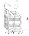
- Fig. 1is a schematic isometric view of an exemplary embodiment of PATM 10.
- the fixtureconsists of parallel plates 12 A-C that are joined together by supportive columns 14 A-C.
- the fixturecan be a monolithic unit.
- Plates 12 A-Ccan made of any material characterized by substantial firmness, and preferably made of any dielectric material known in the art such as FR4/G10; AT7000TM.
- a two dimensional array of probes 16is supported by upper plate 12A and guided by the holes in middle and lower plates 12B and 12C respectively, as to be specified below.
- Upper plate 12Amay further support electronic components 18 and connector 20, which connects PATM 10 to the ACM (not shown).
- probes 16are arranged in a predetermined pattern, namely a rectangular pattern of 8 rows and 16 columns; however, any other pattern such as circular, and any number of probes are applicable.
- FIG. 2is an isometric view diagram of an exemplary embodiment of PATM 10 illustrating the extendability of probe 22.
- probe 22consists of core 24 and sheath 26.
- Core 24can be firmly attached to upper plate 12A and sheath 26 can perform a translational movement with respect to core 24.
- Core 24provides for mechanical support of and substantial electric conductivity with sheath 26, and the translational movement of sheath 26 can be further guided by the holes in middle and lower plates 12B and 12C respectively.
- the holes in lower plates 12B and 12Callow sheath 26 to move freely, so that the probes extend to their full lengths, like probe 22, merely due to the gravitational force.
- Probes not part of the inventionmay be further furnished with more elaborate urging means, besides the gravitational force drive their extending.
- Fig. 3which is not part of the invention and shows a schematic cross-view diagram of an exemplary probe 30 consisting of core 32 and sheath 34.
- Spring 36urges translational movement of core 32 in direction of arrow 38 along axis 40.
- urging meansinclude coils or any other resilient constituents, hydraulic and or pneumatic mechanisms, electromagnetic mechanisms, drive by miniature mechanical gears and etc.
- Signal generator 40is to generate the scanning and treatment electrical signal.
- the signalis directed to the probes employing resistor 42 and de-multiplexers 44 (hereinafter DEMUX).
- DEMUXde-multiplexers 44
- two branchesare shown corresponding each to an array, but any natural number is possible; in some embodiments the number of arrays is 16.
- DEMUXis an HCF4097B analogue 8 channel CMOS multiplexer/demultiplexer (ST Microelectronics, Inc. - 39, Chemin du Champ des Filles C. P. 21 CH 1228 Plan-Les-Ouates GENEVA, Switzerland) with a switching period of at least 50 nano-seconds.
- the input/output device 46has a double role, each role associated with a distinct action mode, i.e sensing and switching modes respectively.
- input/output device 46measures an electric property such as electrical current, associated with the analogue voltage across resistor 42, digitalizes these analogue values and injects the corresponding digital values to the micro-controller 48.
- input/output device 46outputs a digital signal to each one of the DEMUX devices to couple one of channels 50 to signal generator 40. In some embodiments there are 128 channels 50. When a channel is coupled with signal generator 40, electric current for sensing or for treatment can flow through this channel and further through the common ground 52, a return pad (not shown) attached to the body.
- Micro-controller 48is connected to ACM (not shown) through input/output connector 54. In some embodiments, micro-controller 48 and input/output device 46 are implemented as one single component. Micro-controller 48 controls the operation of PATM as follows; it commands input/output device 46, to couple a given channel/s 50 with signal generator 40. Micro-controller 48 measures the voltage drop at resistor 42.
- Fig. 5schematically illustrating exemplary components and circuitry of upper plate 12A.
- Micro-controller 48is electrically connected to DEMUXs 44.
- Each one of output channels 50 of each DEMUX 44is connected by means of wire to a plurality of connectors 56.
- Each connector 56is electrically connected to a corresponding probe of an array of probes 16 as shown in Fig. 1 to which reference is again made.
- connectors 56provide for mechanical support of the probes and a low impedance connection between the output channels and the probes.
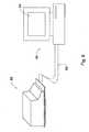
- ACM 60typically a personal computer, includes a graphical user interface (GUI) 64 and a memory storage medium (not shown).
- GUIgraphical user interface
- the distal end of the probessuch as the distal end of sheath 26 of probes 22 protruding from the lower plate as described above with reference to Fig. 2 , to which reference is made again are to be brought into physical contact with the patient's skin at a point of contact (hereinafter referred to as contact site or CS) so as to facilitate effective and uniform electrical conductivity between the each single probe and patient's body.
- CSpoint of contact
- a possible problem underlying the facilitation of an effective electrical conductivity at CSis a potentially high and non-uniform electrical resistance of the skin. This non uniformity is associated among other factors, with the coarseness and or moistness pattern of the skin, structural and or morphological aspects.
- the distal end of the probesis shaped having pointed or sharp tip or edge facing the skin, characterized by relatively small surface area, which results in relatively high pressure applied on the skin at the CS, resulting in a better and more uniform electrical conductivity.
- the distal end of the probesis further furnished with a miniature needle that penetrates the epidermis and or dermis and thus precludes the problems associated with surficial variability.
- the distal end of the probeis further furnished with cap-elements and or covered with a layer of material characterized by substantial elasticity and electrical conductivity.
- the elastic properties of the cap-element or and of the layer covering the distal ends of the probesprovide for physical contact with the skin surface and thus facilitate more uniform and significantly lower electrical resistance at the CS.
- electrically conductive and elastic materialsinclude, inter alia, hydrogels.
- a particular example of a hydrogel materialis a composite of polyaniline nanoparticles and poly(N-vinyl-2-pyrrolidone). It should be stressed, however, that any materials characterized by substantial elasticity and electrical conductivity applicable.
- the electrically conductive elastic material(hereinafter ECEM) is applied, optionally in a reversible manner, onto the distal ends of the probes, as a covering stratum by brushing, smearing or spraying.
- the ECEMcan be applied by immersing the distal ends of the probes into the ECEM. In such a case, complimentary baths and forms for exposing exclusively the tips of the probes are disclosed.
- an ECEMis provided in the form of cap-elements fastened, preferably in a reversible manner, to the tips of the probes.
- an array of such cap-elementsis arranged in a form of a disposable patch, applied to PATM prior to the treatment session.
- Fig. 7Ais a schematic representation of exemplary disposable patch 70, wherein a plurality of cap-elements 72 are embedded, corresponding the pattern in which the probes of PATM (not shown) are arranged.
- Fig. 7Ais a schematic representation of exemplary disposable patch 70, wherein a plurality of cap-elements 72 are embedded, corresponding the pattern in which the probes of PATM (not shown) are arranged.
- FIG. 7Bwhich shows a cross-sectional view of exemplary cap-element 75, wherein fastening portion 76 and CS portion 78 form a continuum with each other.
- Protective layer 80can be optionally employed for covering CS portion 78 and embracing fastening portion 76.
- Fig. 8A and 8Bis a schematic representation of an exemplary fastening mechanism, providing for removably attaching probes 82 to cap-elements 75.
- probes 82are aligned with disposable patch 70 in such a manner that the tips of the probes correspond the locations of cap-elements 75.
- Probes 82are then urged in direction of arrow 84 towards disposable patch 70, or vise versa; after which fastening portions 76 are subsequently fastened to the tips of probes 82.
- Protective layer 80is then removed, exposing CS portions 78 of cap-elements 75.
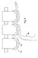
- FIG. 10illustrating application of cap-elements 75, onto a relief of patient's skin 90.
- Cap-elements 75 on probes 82are pressed against patient's skin 90 and adjustably adjoin the relief of skin 90, facilitating lower and more uniform electrical resistance at the CS.
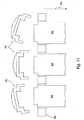
- FIG. 11illustrating the detachment of cap-elements 75 from probes 82.
- Probes 82are retracted into PATM 92 in direction of arrow 94 and cap-elements 75, having bigger exterior circumference than the holes of probes 82, are pushed off by the surface of PATM 92.
- PATMis placed on the area of interest on the skin surface of patient's body and further optionally attached to the body so as to substantially immobilize the PATM relative to the body.
- an area of interestis the center of the lower back of the patient's body, with the lower end located at the upper sacrum; exemplary PATM that can be employed for treating this area is 20 cm wide and 40 cm long, with 2048 pins arranged in 32 columns with 64 pins each column.
- the probes of PATMare then brought into contact with patient's skin, and optionally a return pad, for common ground attached to the body.
- scanningis initiated. Throughout the scanning, the micro-controller is activated in the sensing mode to couple each one of the probes to the signal generator one at a time, while concurrently measuring the drop voltage across the corresponding resistor.
- the effective voltage drop for each probeis stored in the memory storage medium of the ACM; and locations of point of high voltage drops, corresponding to high current flow, and hence to low impedance at a given point, are interpreted as associated with potentially active therapeutic points.
- At the memory storage medium of ACMare conjointly stored predetermined locations of known therapeutically active points on the skin surface of the human body, including acupuncture points, preferably arranged in maps, and optionally classified according to the effect which application of treatment on these points is to produce.
- known therapeutically active points on the skin surface of the human bodyincluding acupuncture points, preferably arranged in maps, and optionally classified according to the effect which application of treatment on these points is to produce.
- complimentary measurements of the patient's bodyare made so that the map can be adjusted to the scale of the patient under treatment.
- the sex, height, and circumference of the bodyfor instance at the fifth lumbar vertebrae, are measured and fed into the ACM.
- GUIis a touch-screen device optionally furnished with a touch pen.
- TESTES to whichever of the following: all known trigger points, acupuncture points, points characterized by proximity to peripheral nerves ends and or other discrete sites on the skin surface of human body that has a presumed capacity to induce whichever therapeutic effect due to TES and or locations characterized by relatively lower local electrical impedance, is in accordance with the present invention and constitute an adequate application thereof.
- the system of the inventionis applicable in therapeutic indications as follows. Pain treatment: back pain, carpal tunnel syndrome, headache, scar pain, Fibromyalgia, neck pain, face pain, shoulder pain, elbow pain, wrist pain, hip pain, knee pain, ankle pain, arthritic pain, peripheral neuropathy, prostatitis and pelvic pain. Indications associated with cancer treatment: anesthesia, post-operative pain control, nausea and vomiting, hastening recovery from the side effects of the various therapies.
Landscapes
- Health & Medical Sciences (AREA)
- Life Sciences & Earth Sciences (AREA)
- General Health & Medical Sciences (AREA)
- Public Health (AREA)
- Heart & Thoracic Surgery (AREA)
- Engineering & Computer Science (AREA)
- Biomedical Technology (AREA)
- Biophysics (AREA)
- Veterinary Medicine (AREA)
- Animal Behavior & Ethology (AREA)
- Nuclear Medicine, Radiotherapy & Molecular Imaging (AREA)
- Radiology & Medical Imaging (AREA)
- Pain & Pain Management (AREA)
- Neurology (AREA)
- Physics & Mathematics (AREA)
- Pathology (AREA)
- Medical Informatics (AREA)
- Molecular Biology (AREA)
- Surgery (AREA)
- Electrotherapy Devices (AREA)
- Measurement Of The Respiration, Hearing Ability, Form, And Blood Characteristics Of Living Organisms (AREA)
Description
- The present invention relates to non-invasive/minimally-invasive medical devices and procedures in general. More specifically the present invention which is defined in
claim 1 relates to an apparatus for scanning and localization of therapeutically active points and application of Transcutaneous Electrical Stimulation (TES) to them. - Cory, PC (1996). Non-invasive, peripheral nerve mapping device and method of use.United States Patent
5,560,372 . - Cory, PC, Cory, JM (2003). Electrode array and skin attachment system for noninvasive nerve location and imaging device.United States Patent
6,564, 079 . - Floweerdew, M, Gadsby, G (1997). A review of the treatment of chronic low back pain with acupuncture-like Transcutaneous electrical nerve stimulation and Transcutaneous electrical nerve stimulation. Complementary Therapies in Medicine. Vol. 5, pp. 193-201.
- Gernignani, G, Olivieri, I, Ruju, G, Pasero, G (1991). Transcutaneous electrical nerve stimulation in ankylosing spondylitis: a double-blind study. Arthritis and Rheumatology. Vol. 34, pp. 788-789.
- Johnson, MI (1998). The analgesic effects and clinical use of acupuncture-like TENS (AL-TENS). Physical Terapy Reviews. Vol. 3, pp. 73-93.
- Johnson, MI (1997). Transcutaneous electrical nerve stimulation (TENS) in the management of labour pain: the experience of over ten thousand women. British Journal of Midwifery. Vol. 5, pp. 400-405.
- Johnson, MI (2000). The clinical effectiveness of TENS in pain management. Critical Reviews in Physical Therapy and Rehabilitation. Vol. 12, pp. 131-149.
- Johnson, MI, Ashton, CH, Thompson, JW (1991). An in-depth study of longterm users of Transcutaneous electrical nerve stimulation (TENS). Inplications for clinical use of TENS. Pain. Vol. 44, pp. 221-229.
- Johnson, MI, Ashton, CH, Thompson, JW (1992). Long term use of transcutaneous electrical nerve stimulation at Newcastle Pain Relief Clinic. Journal of the Royal Society of Medicine. Vol. 85, pp. 267-268.
- Melzack, R, Vetere, P, Finch, L (1983). Transcutaneous electrical nerve stimulation for low back pain. A comparison of TENS and massage for pain and range of motion. Physical Therapy. Vol. 63, pp. 483-493.
- Sjölund, B, Terenius, L, Eriksson, M (1977). Increased cerebrospinal fluid levels of endorphis after electro-acupuncture. Acta Physilogica Scandinavica. Vol. 100, pp. 382-384.
- Chen R, Nickel JC. Acupuncture Ameliorates Symptoms in Men with Chronic Prostatitis/Chronic Pelvic Pain Syndrome. Urology. 2003 Jun;(61)6: 1156-1159.
- Honjo H, Kamoi K., Naya Y, et al. The Effects if Acupuncture for Chronic Pelvic Pain Syndrome with Intravenous Congestion: Preliminary Results. International Journal of Urology. 2004 Aug; 11 (8): 607-612.
- Transcutaneous electrical stimulation, (TES), is a non-invasive technique extensively used by numerous health-care providers worldwide. TES includes peripherally applied transcutaneous electrical stimulation as well as transcutaneous electrical stimulation applied to the head, also known as cranial electrical stimulation (CES). According to some prevalent practices TES is applied intended to stimulate the nerves, typically for an analgesic purpose, also known as transcutaneous electrical nerve stimulation or TENS.
- TENS uses an electrical current to stimulate peripheral nerves ends and acupuncture points across the surface of the skin. This stimulation achieves proven analgesic effects by activating specific natural pain relief mechanisms. Due to its simplicity, TENS can be administered either in clinics by health-care professionals or at home by patients who have purchased one of the numerous TENS devices available in the market. According to the medical literature, there are over 250,000 TENS units prescribed annually in the United States alone. Its ease of use, general safety and portability make it a preferred treatment, oftentimes more favorable than the long term use of medications and nerve blocks for chronic pain. One of the key aspects of TENS is that the technique is non invasive and has a few side effects when compared with drug therapy.
- The proliferation of commercial TENS devices has resulted in numerous variations in terms of the specifics modalities of the treatment. The main types of TENS can be summarized as follows:
- conventional TENS - uses high-frequency pulses of relatively low intensity, which stimulate the nerve root, peripheral nerves, or dermatome. Treatment is applied using relatively large electrodes usually placed at appropriate locations on the pain area;
- acupuncture-like TENS (ALTENS). ALTENS has two accepted different meanings. According to the first, ALTENS refers to the application of relatively high intensity TENS with high frequency electric pulses. According to the second, ALTENS refers to the delivery of TENS over acupuncture points and not over entire skin regions;
- electroacupuncture is quite similar to traditional acupuncture since treatment is applied using needles inserted at specific acupuncture points, , along the body. The needles are then attached to a device that generates continuous electric pulses. The frequency and intensity of the current delivered depends on the condition treated;
- Intense TENS In this case, the treatment is with high intensity, almost unbearable, electrical current for the treatment.
- TES can be also implemented for application of electrical current to trigger points or also myofascial trigger points (henceforth TES of Trigger points or TES-TP). Trigger point therapy, sometimes regarded as one of a group of treatment approaches called neuromuscular therapy, typically involves the application of pressure to tender muscle tissue in order to relieve pain and dysfunction in other parts of the body. It is also referred to as myofascial trigger point therapy.
- Known trigger points, acupuncture points, points characterized by proximity to peripheral nerves ends and or other discrete sites on the skin surface of human body that has a presumed capacity to induce whichever therapeutic effect due to TES and or locations characterized by relatively lower local electrical impedance are hereinafter referred to in general as therapeutically active points.
- Inter alia, the object of the present invention is to teach a method of locating and or identifying therapeutically active points on the skin surface and applying TES to them.
- Particularly, one of the objects of the present invention, is to teach a method of AL-TENS, understood as the delivery of TES over acupuncture points, replacing the traditional needles with localized electrodes or probes. Evidence suggests that AL-TENS produces extra segmental analgesia in a manner similar to that for acupuncture. In two randomized controlled trials in the medical literature the percentage of patients who attain pain relief was found in the range of 88-90% for chronic back pains, better than the placebo effect in this group (40 %) and the effect of conventional TENS (50%). The reasons for the better results with this modality in enduring pain relief was explained by the fact that in addition to the nerve stimulation, AL-TENS induces the release of endorphins causing an accumulative effect over time. As compared with traditional acupuncture, AL-TENS is a safer treatment modality eliminating the risks of infection, bruising, organ damage and pneumothorax, needle breakage's, fear of needles, etc.
- In order to apply AL-TENS treatment, the acupuncture points on the region of the body of interest must be first located. Numerous point-meters are available in the market for locating these points, using the principle of low impedance at the acupuncture points location. Apparatus for scanning the acupuncture points have been disclosed in the literature.
US Patent 6,564,079 discloses an apparatus consisting of an array of electrodes and a skin attachment system for nerve localization. Once a point is located, it is usually marked on the skin surface by using an appropriate marker and then the health-provider decides whether treatment should be applied at such points to achieve the desired analgesic effects. This procedure has several significant drawbacks, information is made necessary relating to finding one point at a time and hence is a time-consuming process; knowledge of acupuncture points location to find the points adequate for the specific pain treatment; marking the points on the skin for later use. This method also entails mechanically marking of the acupuncture points, which is associated with reduced precision and human error. Once an acupuncture point is detected, application of TES requires using an additional apparatus. - A method of scanning for therapeutically active points and application of the therapeutic stimulation of TES by the very same apparatus so far has not been suggested.
- Moreover, a method that will provide for scanning of therapeutically active points and subsequent characterization and or identification of the pertinent points, without involvement of a person having knowledge of acupuncture points location, so far has not been suggested either.
- An apparatus according to the preamble of
claim 1 is known fromUS 5 560 372 . - There is provided in accordance with the present invention, an apparatus including patient applied therapeutic module (henceforth PATM), including a fixture and an array of probes housed in the fixture and an actuating controlling module (henceforth ACM). Conjointly, a relative method not part of the invention, characterized by having a data collecting phase and a therapeutic phase, is provided. The method includes the steps of measuring local electrical impedances of a given skin surface area, locating the points characterized by lower impedances, selecting the desired point/s and applying TES thereto.
- The present invention will be understood and appreciated more fully from the following detailed description taken in conjunction with the appended drawings in which:
Fig.1 is an isometric view diagram of an exemplary embodiment of PATM;Fig. 2 is an isometric view diagram illustrating extension of a probe;Fig. 3 is schematic cross-view diagram of an exemplary probe which is not part of the invention;Fig. 4 is schematic diagram illustrating exemplary configuration PATM's electronics;Fig. 5 is schematic diagram of exemplary outline of PATM's circuit topography;Fig. 6 is schematic diagram illustrating the set-up of the system of the present invention;Fig. 7A is a schematic representation of exemplary disposable patch;Fig. 7B is a detailed cross-view diagram of exemplary cap-element;Fig. 8A is a schematic representation of the probes before they being fastened to the cap-elements;Fig. 8A is a schematic representation illustrating the action of the fastening mechanism;Fig. 9 is a schematic diagram illustrating removal of the protective layer from the cap-elements;Fig.10 illustrating application of cap-elements onto structured relief of patient's skin;Fig. 11 illustrating the detachment of cap-elements from the probes.- While the invention is susceptible to various modifications and alternative forms, specific embodiments thereof have been shown by way of example in the drawings. The components in the drawings are not necessarily to scale, emphasis instead being placed upon clearly illustrating the principles of the present invention. It should be understood, however, that the description herein of specific embodiments is not intended to limit the invention to the particular forms disclosed, but on the contrary, the intention is to cover all modifications, equivalents, and alternatives falling within the spirit and scope of the invention.
- Illustrative embodiments of the invention are described below. In the interest of clarity, not all features Illustrative embodiments of the invention are described below. In the interest of clarity, not all features of an actual implementation are described in this specification. It will be appreciated that in the development of any such actual embodiment, numerous implementation-specific decisions must be made to achieve the developers' specific goals, such as compliance with system-related and business-related constraints, which vary from one implementation to another. Moreover, it will be appreciated that such a development effort might be complex and time-consuming, but would nevertheless be a routine undertaking for those of ordinary skill in the art having the benefit of this disclosure.
- The apparatus of the present invention includes a patient applied therapeutic module (hereinafter PATM), and an actuating controlling module (henceforth ACM). PATM includes a fixture and a plurality of probes. The probes are contained within the fixture, arranged according to a predetermined pattern, otherwise also known in the colloquial language of the electronics art as "bed of nails".
- Reference is now made to
Fig. 1 , which is a schematic isometric view of an exemplary embodiment ofPATM 10. In this example, the fixture consists of parallel plates12 A-C that are joined together by supportive columns14 A-C. According to other examples the fixture can be a monolithic unit. Plates12 A-C can made of any material characterized by substantial firmness, and preferably made of any dielectric material known in the art such as FR4/G10; AT7000™. A two dimensional array ofprobes 16 is supported byupper plate 12A and guided by the holes in middle andlower plates Upper plate 12A may further supportelectronic components 18 andconnector 20, which connectsPATM 10 to the ACM (not shown). In this example, probes16 are arranged in a predetermined pattern, namely a rectangular pattern of 8 rows and 16 columns; however, any other pattern such as circular, and any number of probes are applicable. - Reference is now made to
Fig. 2 , which is an isometric view diagram of an exemplary embodiment ofPATM 10 illustrating the extendability ofprobe 22. In thisexample probe 22 consists ofcore 24 andsheath 26.Core 24 can be firmly attached toupper plate 12A andsheath 26 can perform a translational movement with respect tocore 24.Core 24 provides for mechanical support of and substantial electric conductivity withsheath 26, and the translational movement ofsheath 26 can be further guided by the holes in middle andlower plates lower plates sheath 26 to move freely, so that the probes extend to their full lengths, likeprobe 22, merely due to the gravitational force. Probes not part of the invention may be further furnished with more elaborate urging means, besides the gravitational force drive their extending. Reference is now made toFig. 3 , which is not part of the invention and shows a schematic cross-view diagram of anexemplary probe 30 consisting ofcore 32 andsheath 34.Spring 36 urges translational movement ofcore 32 in direction ofarrow 38 alongaxis 40. A variety of urging means are in accordance with the present invention; examples of urging means include coils or any other resilient constituents, hydraulic and or pneumatic mechanisms, electromagnetic mechanisms, drive by miniature mechanical gears and etc. - Reference is now made to
Fig. 4 illustrating schematically an exemplary configuration of the electronic circuitry onupper plate 12A.Signal generator 40 is to generate the scanning and treatment electrical signal. The signal is directed to theprobes employing resistor 42 and de-multiplexers44 (hereinafter DEMUX). In this example two branches are shown corresponding each to an array, but any natural number is possible; in some embodiments the number of arrays is 16. In some embodiments, DEMUX is an HCF4097B analogue 8 channel CMOS multiplexer/demultiplexer (ST Microelectronics, Inc. - 39, Chemin du Champ des Filles C. P. 21 CH 1228 Plan-Les-Ouates GENEVA, Switzerland) with a switching period of at least 50 nano-seconds. The input/output device 46 has a double role, each role associated with a distinct action mode, i.e sensing and switching modes respectively. At the sensing mode, input/output device 46 measures an electric property such as electrical current, associated with the analogue voltage acrossresistor 42, digitalizes these analogue values and injects the corresponding digital values to themicro-controller 48. At the switching mode, input/output device 46 outputs a digital signal to each one of the DEMUX devices to couple one ofchannels 50 to signalgenerator 40. In some embodiments there are 128channels 50. When a channel is coupled withsignal generator 40, electric current for sensing or for treatment can flow through this channel and further through thecommon ground 52, a return pad (not shown) attached to the body.Micro-controller 48 is connected to ACM (not shown) through input/output connector 54. In some embodiments,micro-controller 48 and input/output device 46 are implemented as one single component.Micro-controller 48 controls the operation of PATM as follows; it commands input/output device 46, to couple a given channel/s50 withsignal generator 40.Micro-controller 48 measures the voltage drop atresistor 42. - Reference is now made to
Fig. 5 schematically illustrating exemplary components and circuitry ofupper plate 12A.Micro-controller 48 is electrically connected toDEMUXs 44. Each one ofoutput channels 50 of each DEMUX44 is connected by means of wire to a plurality ofconnectors 56. Eachconnector 56 is electrically connected to a corresponding probe of an array ofprobes 16 as shown inFig. 1 to which reference is again made. Referring again toFig. 5 ,connectors 56 provide for mechanical support of the probes and a low impedance connection between the output channels and the probes. - Reference is now made to
Fig. 6 schematically illustrating a functional set-up embodying the present invention. In the set-up PATM 10 is connected toACM 60 by means ofcable 62.ACM 60, typically a personal computer, includes a graphical user interface (GUI)64 and a memory storage medium (not shown). - According to the present invention, the distal end of the probes, such as the distal end of
sheath 26 ofprobes 22 protruding from the lower plate as described above with reference toFig. 2 , to which reference is made again are to be brought into physical contact with the patient's skin at a point of contact (hereinafter referred to as contact site or CS) so as to facilitate effective and uniform electrical conductivity between the each single probe and patient's body. A possible problem underlying the facilitation of an effective electrical conductivity at CS is a potentially high and non-uniform electrical resistance of the skin. This non uniformity is associated among other factors, with the coarseness and or moistness pattern of the skin, structural and or morphological aspects. - Several approaches to overcome the aforementioned potential conductivity inconsistency are disclosed below. According to some embodiments, the distal end of the probes is shaped having pointed or sharp tip or edge facing the skin, characterized by relatively small surface area, which results in relatively high pressure applied on the skin at the CS, resulting in a better and more uniform electrical conductivity.
- According to some other embodiments, the distal end of the probes is further furnished with a miniature needle that penetrates the epidermis and or dermis and thus precludes the problems associated with surficial variability.
- According to yet other embodiments, the distal end of the probe is further furnished with cap-elements and or covered with a layer of material characterized by substantial elasticity and electrical conductivity. The elastic properties of the cap-element or and of the layer covering the distal ends of the probes provide for physical contact with the skin surface and thus facilitate more uniform and significantly lower electrical resistance at the CS. Examples of such electrically conductive and elastic materials include,inter alia, hydrogels. A particular example of a hydrogel material is a composite of polyaniline nanoparticles and poly(N-vinyl-2-pyrrolidone). It should be stressed, however, that any materials characterized by substantial elasticity and electrical conductivity applicable.
- According to some embodiments, the electrically conductive elastic material (hereinafter ECEM) is applied, optionally in a reversible manner, onto the distal ends of the probes, as a covering stratum by brushing, smearing or spraying. Alternatively, the ECEM can be applied by immersing the distal ends of the probes into the ECEM. In such a case, complimentary baths and forms for exposing exclusively the tips of the probes are disclosed.
- According to some preferred embodiments, an ECEM is provided in the form of cap-elements fastened, preferably in a reversible manner, to the tips of the probes. In some examples, an array of such cap-elements is arranged in a form of a disposable patch, applied to PATM prior to the treatment session. Reference is now made to
Fig. 7A , which is a schematic representation of exemplarydisposable patch 70, wherein a plurality of cap-elements 72 are embedded, corresponding the pattern in which the probes of PATM (not shown) are arranged. Reference is now made toFig. 7B , which shows a cross-sectional view of exemplary cap-element 75, wherein fasteningportion 76 andCS portion 78 form a continuum with each other.Protective layer 80 can be optionally employed for coveringCS portion 78 and embracingfastening portion 76. - Reference is now made to
Fig. 8A and8B , which is a schematic representation of an exemplary fastening mechanism, providing for removably attachingprobes 82 to cap-elements 75. Initially, probes82 are aligned withdisposable patch 70 in such a manner that the tips of the probes correspond the locations of cap-elements 75.Probes 82 are then urged in direction ofarrow 84 towardsdisposable patch 70, orvise versa; after whichfastening portions 76 are subsequently fastened to the tips ofprobes 82. Subsequently, as can be seen inFig. 9 to which reference is now made,Protective layer 80 is then removed, exposingCS portions 78 of cap-elements 75. - Reference is now made to
Fig. 10 , illustrating application of cap-elements 75, onto a relief of patient'sskin 90. Cap-elements 75 onprobes 82 are pressed against patient'sskin 90 and adjustably adjoin the relief ofskin 90, facilitating lower and more uniform electrical resistance at the CS. - Reference is now made to
Fig. 11 , illustrating the detachment of cap-elements 75 from probes82.Probes 82 are retracted intoPATM 92 in direction ofarrow 94 and cap-elements 75, having bigger exterior circumference than the holes ofprobes 82, are pushed off by the surface ofPATM 92. - According to a method not part of the present invention, PATM is placed on the area of interest on the skin surface of patient's body and further optionally attached to the body so as to substantially immobilize the PATM relative to the body. In a preferred embodiment of the present invention, an area of interest is the center of the lower back of the patient's body, with the lower end located at the upper sacrum; exemplary PATM that can be employed for treating this area is 20 cm wide and 40 cm long, with 2048 pins arranged in 32 columns with 64 pins each column. The probes of PATM are then brought into contact with patient's skin, and optionally a return pad, for common ground attached to the body.
- Using the input/output device, scanning is initiated. Throughout the scanning, the micro-controller is activated in the sensing mode to couple each one of the probes to the signal generator one at a time, while concurrently measuring the drop voltage across the corresponding resistor. The effective voltage drop for each probe is stored in the memory storage medium of the ACM; and locations of point of high voltage drops, corresponding to high current flow, and hence to low impedance at a given point, are interpreted as associated with potentially active therapeutic points.
- According to some embodiments of the method of the present invention, at the memory storage medium of ACM are conjointly stored predetermined locations of known therapeutically active points on the skin surface of the human body, including acupuncture points, preferably arranged in maps, and optionally classified according to the effect which application of treatment on these points is to produce. Optionally, complimentary measurements of the patient's body are made so that the map can be adjusted to the scale of the patient under treatment. In some preferred embodiments, the sex, height, and circumference of the body, for instance at the fifth lumbar vertebrae, are measured and fed into the ACM. The relative locations of potentially active therapeutic points, found during the scanning, are then superimposed with the predetermined locations of known therapeutically active points, at the region where PATM was applied, stored at the memory storage medium of ACM. The therapeutically active points available for application of the TES are then identified and presented to a human operator on GUI. Desired therapeutically active point/s are then selected by the human operator, and parameters of TENS to be applied such as duration, intensity, repetitiveness, etc. are determined. According to some preferred embodiments, GUI is a touch-screen device optionally furnished with a touch pen. After selecting the points and determining aforementioned parameters, a switching mode is invoked by using the input/output device, during which the channel corresponding the probe at the therapeutically, active point, whereto treatment to be applied, is coupled with the signal generator.
- Application of the TES to whichever of the following: all known trigger points, acupuncture points, points characterized by proximity to peripheral nerves ends and or other discrete sites on the skin surface of human body that has a presumed capacity to induce whichever therapeutic effect due to TES and or locations characterized by relatively lower local electrical impedance, is in accordance with the present invention and constitute an adequate application thereof.
- The system of the invention is applicable in therapeutic indications as follows. Pain treatment: back pain, carpal tunnel syndrome, headache, scar pain, Fibromyalgia, neck pain, face pain, shoulder pain, elbow pain, wrist pain, hip pain, knee pain, ankle pain, arthritic pain, peripheral neuropathy, prostatitis and pelvic pain. Indications associated with cancer treatment: anesthesia, post-operative pain control, nausea and vomiting, hastening recovery from the side effects of the various therapies.
- It will be appreciated that the present invention is not limited by what has been particularly described and shown hereinabove and that numerous modifications, all of which fall within the scope of the present invention, exist. Rather the scope of the invention is defined by the claims which follow:
Claims (9)
- An apparatus for locating therapeutically active points, said apparatus comprising:a patient applied therapeutic module (PATM) (10), said module comprising:a plurality of probes (16, 82), each of said probes exhibits a core (24, 32) and a sheath (26, 34),a fixture (12A - 12C) arranged to secure a first one of said cores and said sheaths of said plurality of probes in at least one array, and further arranged to allow a second one of said cores and said sheaths of said plurality of probes to extend longitudinally from said fixture up to a respective maximum length as a translational movement with respect to said fixture, said longitudinal extension of each of said second one of said cores and said sheaths of said plurality of probes being independent of the longitudinal extension translational movement and length of any other of said second one of said cores and said sheaths of said plurality of probes, andan electronic circuitry comprising a signal generator (40) and arranged to sense the impedance associated with each of said probes; andan actuating controlling module (ACM) in communication with said electronic circuitry of said PATM, said ACM comprising:i. a graphical user interface (64), andii. a memory storage medium;wherein, said ACM is arranged to receive from said PATM said sensed impedance associated with each of said probes, store said received impedances on said memory storage medium and display, utilizing said graphical user interface, relative locations of active therapeutic points responsive to said stored received impedances,characterized in that said apparatus is further adapted for applying transcutaneous electrical stimulation to said points, whereby said second one of said cores and sheaths of said plurality of probes are adapted to extend longitudinally from said fixture merely due to the gravitational force.
- The apparatus for locating therapeutically active points as in claim 1, wherein said ACM is a personal computer.
- The apparatus for locating therapeutically active points as in any of the preceding claims, further comprising an electrically conductive return pad physically attached to a patient body being a common electric ground point (52); wherein said probes are electrically coupleable, discreetly, one at a time, to a signal generator (40); and wherein said second one of said cores and said sheaths of said plurality of probes are extendable outwards from said fixture such that the distal ends thereof physically adjoin the skin surface of the treated skin (90) and found in electrical contact with it.
- The apparatus for locating therapeutically active points as in claim 3, wherein a difference of potentials of a predetermined magnitude is crated between said common electric ground point (52) and said signal generator (40); wherein said difference of potentials is implemented for an objective selected from the group consisting of: measuring local impedance at a contact point and applying of transcutaneous electrical stimulation.
- The apparatus for locating therapeutically active points as in claim 1, wherein a distal end of said second one of said cores and said sheaths of said plurality of probes having a structural characteristic selected from the group consisting of: a pointed tip, a sharp edge and a miniature needle.
- The apparatus for locating therapeutically active points as in claim 5, wherein said distal end of said second one of said cores and said sheaths of said plurality of probes are further covered by stratum of electrically conductive elastic material (72).
- The apparatus for locating therapeutically active points as in claim 6, wherein said electrically conductive elastic material is hydrogel applied onto said distal end of said second one of said cores and said sheaths of said plurality of probes by a technique selected from the group consisting of: brushing, smearing, spraying and immersing.
- The apparatus for locating therapeutically active points as in claim 6, wherein said distal end of said second one of said cores and said sheaths of said plurality of probes are further furnished with cap-elements (72, 75)characterized by substantial electrical conductivity and elasticity.
- The apparatus for locating therapeutically active points as in claim 8, wherein said cap-elements (72, 75) having a structural characteristic selected from the group consisting of: a fastening portion, a contact site portion, wherein an array of said cap-elements are embedded in a detachable patch in a predetermined arrangement pattern.
Applications Claiming Priority (2)
| Application Number | Priority Date | Filing Date | Title |
|---|---|---|---|
| US80929906P | 2006-05-31 | 2006-05-31 | |
| PCT/IL2007/000661WO2007138595A2 (en) | 2006-05-31 | 2007-05-31 | Transcutaneous electrical therapeutic device |
Publications (3)
| Publication Number | Publication Date |
|---|---|
| EP2021067A2 EP2021067A2 (en) | 2009-02-11 |
| EP2021067A4 EP2021067A4 (en) | 2013-02-13 |
| EP2021067B1true EP2021067B1 (en) | 2014-09-10 |
Family
ID=38779092
Family Applications (1)
| Application Number | Title | Priority Date | Filing Date |
|---|---|---|---|
| EP07736401.6ANot-in-forceEP2021067B1 (en) | 2006-05-31 | 2007-05-31 | Transcutaneous electrical therapeutic device |
Country Status (3)
| Country | Link |
|---|---|
| US (1) | US8355790B2 (en) |
| EP (1) | EP2021067B1 (en) |
| WO (1) | WO2007138595A2 (en) |
Families Citing this family (37)
| Publication number | Priority date | Publication date | Assignee | Title |
|---|---|---|---|---|
| US11224742B2 (en) | 2006-10-02 | 2022-01-18 | Emkinetics, Inc. | Methods and devices for performing electrical stimulation to treat various conditions |
| US10786669B2 (en) | 2006-10-02 | 2020-09-29 | Emkinetics, Inc. | Method and apparatus for transdermal stimulation over the palmar and plantar surfaces |
| DE102009048950B4 (en) | 2009-10-10 | 2012-07-05 | Erhard Schöndorf | Apparatus for the stimulation current treatment of the human body |
| EP2493551A4 (en) | 2009-10-26 | 2013-04-17 | Emkinetics Inc | Method and apparatus for electromagnetic stimulation of nerve, muscle, and body tissues |
| WO2011112262A2 (en) | 2010-03-11 | 2011-09-15 | Weinstock Ronald J | Emf probe configurations for electro-modulation of ionic channels of cells and methods of use thereof |
| EP2383014A1 (en)* | 2010-04-29 | 2011-11-02 | Koninklijke Philips Electronics N.V. | Transcutaneous electro-stimulation device with a matrix of electrodes |
| US9114248B2 (en)* | 2010-10-04 | 2015-08-25 | Nervomatrix Ltd. | Electrode for finding points of low impedance and applying electrical stimulation thereto |
| WO2013071309A1 (en) | 2011-11-11 | 2013-05-16 | The Regents Of The University Of California | Transcutaneous spinal cord stimulation: noninvasive tool for activation of locomotor circuitry |
| CN103869957B (en)* | 2012-12-18 | 2018-02-23 | 富泰华工业(深圳)有限公司 | Tactile feedback system and its method that tactile feedback is provided |
| US9174053B2 (en) | 2013-03-08 | 2015-11-03 | Boston Scientific Neuromodulation Corporation | Neuromodulation using modulated pulse train |
| US8870798B2 (en) | 2013-03-14 | 2014-10-28 | CyMedica, Inc. | Systems and methods for treating human joints |
| US9072898B2 (en) | 2013-03-14 | 2015-07-07 | CyMedica, Inc. | System and methods for treating or supporting human joints or a portion of the human body |
| WO2014144785A1 (en) | 2013-03-15 | 2014-09-18 | The Regents Of The University Of California | Multi-site transcutaneous electrical stimulation of the spinal cord for facilitation of locomotion |
| US10137299B2 (en) | 2013-09-27 | 2018-11-27 | The Regents Of The University Of California | Engaging the cervical spinal cord circuitry to re-enable volitional control of hand function in tetraplegic subjects |
| WO2016009424A1 (en)* | 2014-07-13 | 2016-01-21 | Nibs Neuroscience Technologies Ltd. | Electrode headset grid and use thereof in the non-invasive brain stimulation and monitoring |
| WO2016029159A2 (en) | 2014-08-21 | 2016-02-25 | The Regents Of The University Of California | Regulation of autonomic control of bladder voiding after a complete spinal cord injury |
| AU2015308779B2 (en) | 2014-08-27 | 2020-06-25 | The Regents Of The University Of California | Multi-electrode array for spinal cord epidural stimulation |
| US9737717B2 (en)* | 2014-09-15 | 2017-08-22 | Boston Scientific Neuromodulation Corporation | Graphical user interface for programming neurostimulation pulse patterns |
| JP6452836B2 (en) | 2014-11-04 | 2019-01-16 | ボストン サイエンティフィック ニューロモデュレイション コーポレイション | Method and apparatus for programming complex neural stimulation patterns |
| WO2016125159A1 (en) | 2015-02-03 | 2016-08-11 | Nibs Neuroscience Technologies Ltd. | Early diagnosis and treatment of alzheimer disease and mild cognitive impairment |
| AU2016297965B2 (en) | 2015-07-30 | 2019-04-04 | Boston Scientific Neuromodulation Corporation | User interface for custom patterned electrical stimulation |
| US11298533B2 (en) | 2015-08-26 | 2022-04-12 | The Regents Of The University Of California | Concerted use of noninvasive neuromodulation device with exoskeleton to enable voluntary movement and greater muscle activation when stepping in a chronically paralyzed subject |
| WO2017066187A1 (en) | 2015-10-15 | 2017-04-20 | Boston Scientific Neuromodulation Corporation | User interface for neurostimulation waveform composition |
| US11097122B2 (en) | 2015-11-04 | 2021-08-24 | The Regents Of The University Of California | Magnetic stimulation of the spinal cord to restore control of bladder and/or bowel |
| US11235154B2 (en) | 2017-02-17 | 2022-02-01 | The University Of British Columbia | Apparatus and methods for maintaining physiological functions |
| WO2018217791A1 (en) | 2017-05-23 | 2018-11-29 | The Regents Of The University Of California | Accessing spinal networks to address sexual dysfunction |
| EP3974021B1 (en) | 2017-06-30 | 2023-06-14 | ONWARD Medical N.V. | A system for neuromodulation |
| CN107928669B (en)* | 2017-11-06 | 2020-07-14 | 上海道生医疗科技有限公司 | Acupuncture point impedance detection method and handheld acupuncture point impedance detector |
| US12357828B2 (en) | 2017-12-05 | 2025-07-15 | Ecole Polytechnique Federale De Lausanne (Epfl) | System for planning and/or providing neuromodulation |
| WO2019110400A1 (en) | 2017-12-05 | 2019-06-13 | Ecole Polytechnique Federale De Lausanne (Epfl) | A system for planning and/or providing neuromodulation |
| US20210353205A1 (en) | 2018-09-13 | 2021-11-18 | Quantalx Neuroscience Ltd | A reliable tool for evaluating brain health |
| DE18205821T1 (en) | 2018-11-13 | 2020-12-24 | Gtx Medical B.V. | CONTROL SYSTEM FOR MOTION RECONSTRUCTION AND / OR RECOVERY FOR A PATIENT |
| EP3695878B1 (en) | 2019-02-12 | 2023-04-19 | ONWARD Medical N.V. | A system for neuromodulation |
| CA3158711A1 (en)* | 2019-11-18 | 2021-05-27 | M.D. Anna O. LIKHACHEVA | System for conforming treatment applicators to non-uniform surfaces |
| DE19211698T1 (en) | 2019-11-27 | 2021-09-02 | Onward Medical B.V. | Neuromodulation system |
| EP3827875B1 (en) | 2019-11-27 | 2023-07-05 | ONWARD Medical N.V. | Neuromodulation system |
| US20220257149A1 (en)* | 2021-02-14 | 2022-08-18 | Neursantys, Inc. | Systems and methods for detecting and treating neurophysiological impairment |
Family Cites Families (11)
| Publication number | Priority date | Publication date | Assignee | Title |
|---|---|---|---|---|
| US5070873A (en) | 1987-02-13 | 1991-12-10 | Sigmedics, Inc. | Method of and apparatus for electrically stimulating quadriceps muscles of an upper motor unit paraplegic |
| US4838272A (en)* | 1987-08-19 | 1989-06-13 | The Regents Of The University Of California | Method and apparatus for adaptive closed loop electrical stimulation of muscles |
| US5560372A (en) | 1994-02-02 | 1996-10-01 | Cory; Philip C. | Non-invasive, peripheral nerve mapping device and method of use |
| US6141575A (en)* | 1996-08-16 | 2000-10-31 | Price; Michael A. | Electrode assemblies |
| US6181961B1 (en)* | 1997-12-16 | 2001-01-30 | Richard L. Prass | Method and apparatus for an automatic setup of a multi-channel nerve integrity monitoring system |
| US6463327B1 (en) | 1998-06-11 | 2002-10-08 | Cprx Llc | Stimulatory device and methods to electrically stimulate the phrenic nerve |
| US6512945B1 (en)* | 1999-06-10 | 2003-01-28 | Harbinger Medical, Inc. | Method of noninvasively determining a patient's susceptibility to arrhythmia |
| US6564079B1 (en) | 2000-07-27 | 2003-05-13 | Ckm Diagnostics, Inc. | Electrode array and skin attachment system for noninvasive nerve location and imaging device |
| US7035691B2 (en)* | 2002-01-15 | 2006-04-25 | Therapeutic Innovations, Inc. | Resonant muscle stimulator |
| US7016737B2 (en)* | 2002-03-06 | 2006-03-21 | Loma Linda University | Method and device for wound healing |
| US20060047194A1 (en)* | 2004-08-31 | 2006-03-02 | Grigorov Ilya L | Electrode apparatus and system |
- 2007
- 2007-05-31EPEP07736401.6Apatent/EP2021067B1/ennot_activeNot-in-force
- 2007-05-31WOPCT/IL2007/000661patent/WO2007138595A2/enactiveApplication Filing
- 2007-05-31USUS12/301,464patent/US8355790B2/ennot_activeExpired - Fee Related
Also Published As
| Publication number | Publication date |
|---|---|
| US8355790B2 (en) | 2013-01-15 |
| WO2007138595A2 (en) | 2007-12-06 |
| EP2021067A2 (en) | 2009-02-11 |
| US20090198305A1 (en) | 2009-08-06 |
| WO2007138595A3 (en) | 2009-04-23 |
| EP2021067A4 (en) | 2013-02-13 |
Similar Documents
| Publication | Publication Date | Title |
|---|---|---|
| EP2021067B1 (en) | Transcutaneous electrical therapeutic device | |
| US20230072751A1 (en) | Devices, systems and methods for treating pain with electrical stimulation | |
| Shin et al. | Evoked haptic sensations in the hand via non-invasive proximal nerve stimulation | |
| CN101563056B (en) | electrotherapy equipment | |
| KR102390107B1 (en) | Topical neurological stimulation | |
| US7865236B2 (en) | Active electrode, bio-impedance based, tissue discrimination system and methods of use | |
| EP2928548B1 (en) | Systems to place one or more leads in tissue to electrically stimulate nerves of passage to treat pain | |
| CN101534898B (en) | Bipolar stimulation/recording device with widely spaced electrodes | |
| Bao et al. | Electrode placement on the forearm for selective stimulation of finger extension/flexion | |
| Popović-Maneski et al. | Multi-pad electrode for effective grasping: design | |
| US20110082383A1 (en) | Active Electrode, Bio-Impedance Based, Tissue Discrimination System and Methods of Use | |
| Pascual-Valdunciel et al. | Intramuscular stimulation of muscle afferents attains prolonged tremor reduction in essential tremor patients | |
| US10493272B1 (en) | Inferential electrical stimulation device with targeting capabilities | |
| MX2014006440A (en) | Allergy testing device and method of testing for allergies. | |
| US20240269465A1 (en) | Multi-electrode pad for transcutaneous stimulation | |
| JP7434163B2 (en) | non-invasive nerve stimulation | |
| KR102544729B1 (en) | multiple cathodes | |
| Serbia | INTFES: a multi-pad electrode system for selective transcutaneous electrical muscle stimulation | |
| EP4387685B1 (en) | Injectrode with multiple electrical sensors | |
| RU103733U1 (en) | INSTALLATION FOR DIAGNOSIS AND TREATMENT OF THE PATIENT | |
| KR20160060364A (en) | Wireless EMG device with integrated disposable stimulation electrode gel electrolyte | |
| Fisher et al. | Neuroprostheses for somatosensory function | |
| Sha | A surface electrode array-based system for functional electrical stimulation | |
| Silveira | Development and evaluation of a surface array based system to assist electrode positioning in FES for drop foot | |
| Lane | The effects of muscle belly vibration at varying muscle lengths on corticospinal excitability: a TMS study |
Legal Events
| Date | Code | Title | Description |
|---|---|---|---|
| PUAI | Public reference made under article 153(3) epc to a published international application that has entered the european phase | Free format text:ORIGINAL CODE: 0009012 | |
| 17P | Request for examination filed | Effective date:20081120 | |
| AK | Designated contracting states | Kind code of ref document:A2 Designated state(s):AT BE BG CH CY CZ DE DK EE ES FI FR GB GR HU IE IS IT LI LT LU LV MC MT NL PL PT RO SE SI SK TR | |
| AX | Request for extension of the european patent | Extension state:AL BA HR MK RS | |
| R17D | Deferred search report published (corrected) | Effective date:20090423 | |
| DAX | Request for extension of the european patent (deleted) | ||
| RAP1 | Party data changed (applicant data changed or rights of an application transferred) | Owner name:NERVOMATRIX LTD | |
| RIN1 | Information on inventor provided before grant (corrected) | Inventor name:ROTSTEIN, HECTOR Inventor name:NARODITSKY, MICHAEL | |
| A4 | Supplementary search report drawn up and despatched | Effective date:20130110 | |
| RIC1 | Information provided on ipc code assigned before grant | Ipc:A61N 1/02 20060101AFI20130104BHEP | |
| GRAP | Despatch of communication of intention to grant a patent | Free format text:ORIGINAL CODE: EPIDOSNIGR1 | |
| INTG | Intention to grant announced | Effective date:20130918 | |
| GRAP | Despatch of communication of intention to grant a patent | Free format text:ORIGINAL CODE: EPIDOSNIGR1 | |
| INTG | Intention to grant announced | Effective date:20140211 | |
| GRAS | Grant fee paid | Free format text:ORIGINAL CODE: EPIDOSNIGR3 | |
| GRAA | (expected) grant | Free format text:ORIGINAL CODE: 0009210 | |
| AK | Designated contracting states | Kind code of ref document:B1 Designated state(s):AT BE BG CH CY CZ DE DK EE ES FI FR GB GR HU IE IS IT LI LT LU LV MC MT NL PL PT RO SE SI SK TR | |
| REG | Reference to a national code | Ref country code:GB Ref legal event code:FG4D | |
| REG | Reference to a national code | Ref country code:CH Ref legal event code:EP | |
| REG | Reference to a national code | Ref country code:IE Ref legal event code:FG4D | |
| REG | Reference to a national code | Ref country code:AT Ref legal event code:REF Ref document number:686343 Country of ref document:AT Kind code of ref document:T Effective date:20141015 | |
| REG | Reference to a national code | Ref country code:SE Ref legal event code:TRGR | |
| REG | Reference to a national code | Ref country code:DE Ref legal event code:R096 Ref document number:602007038492 Country of ref document:DE Effective date:20141023 | |
| PG25 | Lapsed in a contracting state [announced via postgrant information from national office to epo] | Ref country code:ES Free format text:LAPSE BECAUSE OF FAILURE TO SUBMIT A TRANSLATION OF THE DESCRIPTION OR TO PAY THE FEE WITHIN THE PRESCRIBED TIME-LIMIT Effective date:20140910 Ref country code:GR Free format text:LAPSE BECAUSE OF FAILURE TO SUBMIT A TRANSLATION OF THE DESCRIPTION OR TO PAY THE FEE WITHIN THE PRESCRIBED TIME-LIMIT Effective date:20141211 Ref country code:FI Free format text:LAPSE BECAUSE OF FAILURE TO SUBMIT A TRANSLATION OF THE DESCRIPTION OR TO PAY THE FEE WITHIN THE PRESCRIBED TIME-LIMIT Effective date:20140910 Ref country code:LT Free format text:LAPSE BECAUSE OF FAILURE TO SUBMIT A TRANSLATION OF THE DESCRIPTION OR TO PAY THE FEE WITHIN THE PRESCRIBED TIME-LIMIT Effective date:20140910 | |
| REG | Reference to a national code | Ref country code:NL Ref legal event code:VDEP Effective date:20140910 | |
| REG | Reference to a national code | Ref country code:LT Ref legal event code:MG4D | |
| PG25 | Lapsed in a contracting state [announced via postgrant information from national office to epo] | Ref country code:CY Free format text:LAPSE BECAUSE OF FAILURE TO SUBMIT A TRANSLATION OF THE DESCRIPTION OR TO PAY THE FEE WITHIN THE PRESCRIBED TIME-LIMIT Effective date:20140910 Ref country code:LV Free format text:LAPSE BECAUSE OF FAILURE TO SUBMIT A TRANSLATION OF THE DESCRIPTION OR TO PAY THE FEE WITHIN THE PRESCRIBED TIME-LIMIT Effective date:20140910 | |
| REG | Reference to a national code | Ref country code:AT Ref legal event code:MK05 Ref document number:686343 Country of ref document:AT Kind code of ref document:T Effective date:20140910 | |
| PG25 | Lapsed in a contracting state [announced via postgrant information from national office to epo] | Ref country code:NL Free format text:LAPSE BECAUSE OF FAILURE TO SUBMIT A TRANSLATION OF THE DESCRIPTION OR TO PAY THE FEE WITHIN THE PRESCRIBED TIME-LIMIT Effective date:20140910 | |
| PG25 | Lapsed in a contracting state [announced via postgrant information from national office to epo] | Ref country code:CZ Free format text:LAPSE BECAUSE OF FAILURE TO SUBMIT A TRANSLATION OF THE DESCRIPTION OR TO PAY THE FEE WITHIN THE PRESCRIBED TIME-LIMIT Effective date:20140910 Ref country code:RO Free format text:LAPSE BECAUSE OF FAILURE TO SUBMIT A TRANSLATION OF THE DESCRIPTION OR TO PAY THE FEE WITHIN THE PRESCRIBED TIME-LIMIT Effective date:20140910 Ref country code:SK Free format text:LAPSE BECAUSE OF FAILURE TO SUBMIT A TRANSLATION OF THE DESCRIPTION OR TO PAY THE FEE WITHIN THE PRESCRIBED TIME-LIMIT Effective date:20140910 Ref country code:EE Free format text:LAPSE BECAUSE OF FAILURE TO SUBMIT A TRANSLATION OF THE DESCRIPTION OR TO PAY THE FEE WITHIN THE PRESCRIBED TIME-LIMIT Effective date:20140910 Ref country code:IS Free format text:LAPSE BECAUSE OF FAILURE TO SUBMIT A TRANSLATION OF THE DESCRIPTION OR TO PAY THE FEE WITHIN THE PRESCRIBED TIME-LIMIT Effective date:20150110 Ref country code:PT Free format text:LAPSE BECAUSE OF FAILURE TO SUBMIT A TRANSLATION OF THE DESCRIPTION OR TO PAY THE FEE WITHIN THE PRESCRIBED TIME-LIMIT Effective date:20150112 | |
| PG25 | Lapsed in a contracting state [announced via postgrant information from national office to epo] | Ref country code:AT Free format text:LAPSE BECAUSE OF FAILURE TO SUBMIT A TRANSLATION OF THE DESCRIPTION OR TO PAY THE FEE WITHIN THE PRESCRIBED TIME-LIMIT Effective date:20140910 Ref country code:PL Free format text:LAPSE BECAUSE OF FAILURE TO SUBMIT A TRANSLATION OF THE DESCRIPTION OR TO PAY THE FEE WITHIN THE PRESCRIBED TIME-LIMIT Effective date:20140910 | |
| REG | Reference to a national code | Ref country code:DE Ref legal event code:R097 Ref document number:602007038492 Country of ref document:DE | |
| PLBE | No opposition filed within time limit | Free format text:ORIGINAL CODE: 0009261 | |
| STAA | Information on the status of an ep patent application or granted ep patent | Free format text:STATUS: NO OPPOSITION FILED WITHIN TIME LIMIT | |
| PG25 | Lapsed in a contracting state [announced via postgrant information from national office to epo] | Ref country code:DK Free format text:LAPSE BECAUSE OF FAILURE TO SUBMIT A TRANSLATION OF THE DESCRIPTION OR TO PAY THE FEE WITHIN THE PRESCRIBED TIME-LIMIT Effective date:20140910 | |
| 26N | No opposition filed | Effective date:20150611 | |
| PG25 | Lapsed in a contracting state [announced via postgrant information from national office to epo] | Ref country code:SI Free format text:LAPSE BECAUSE OF FAILURE TO SUBMIT A TRANSLATION OF THE DESCRIPTION OR TO PAY THE FEE WITHIN THE PRESCRIBED TIME-LIMIT Effective date:20140910 | |
| REG | Reference to a national code | Ref country code:CH Ref legal event code:PL | |
| PG25 | Lapsed in a contracting state [announced via postgrant information from national office to epo] | Ref country code:MC Free format text:LAPSE BECAUSE OF FAILURE TO SUBMIT A TRANSLATION OF THE DESCRIPTION OR TO PAY THE FEE WITHIN THE PRESCRIBED TIME-LIMIT Effective date:20140910 Ref country code:LI Free format text:LAPSE BECAUSE OF NON-PAYMENT OF DUE FEES Effective date:20150531 Ref country code:LU Free format text:LAPSE BECAUSE OF FAILURE TO SUBMIT A TRANSLATION OF THE DESCRIPTION OR TO PAY THE FEE WITHIN THE PRESCRIBED TIME-LIMIT Effective date:20150531 Ref country code:CH Free format text:LAPSE BECAUSE OF NON-PAYMENT OF DUE FEES Effective date:20150531 | |
| REG | Reference to a national code | Ref country code:IE Ref legal event code:MM4A | |
| PG25 | Lapsed in a contracting state [announced via postgrant information from national office to epo] | Ref country code:IE Free format text:LAPSE BECAUSE OF NON-PAYMENT OF DUE FEES Effective date:20150531 | |
| REG | Reference to a national code | Ref country code:FR Ref legal event code:PLFP Year of fee payment:10 | |
| PG25 | Lapsed in a contracting state [announced via postgrant information from national office to epo] | Ref country code:BE Free format text:LAPSE BECAUSE OF FAILURE TO SUBMIT A TRANSLATION OF THE DESCRIPTION OR TO PAY THE FEE WITHIN THE PRESCRIBED TIME-LIMIT Effective date:20140910 | |
| PG25 | Lapsed in a contracting state [announced via postgrant information from national office to epo] | Ref country code:MT Free format text:LAPSE BECAUSE OF FAILURE TO SUBMIT A TRANSLATION OF THE DESCRIPTION OR TO PAY THE FEE WITHIN THE PRESCRIBED TIME-LIMIT Effective date:20140910 | |
| PG25 | Lapsed in a contracting state [announced via postgrant information from national office to epo] | Ref country code:HU Free format text:LAPSE BECAUSE OF FAILURE TO SUBMIT A TRANSLATION OF THE DESCRIPTION OR TO PAY THE FEE WITHIN THE PRESCRIBED TIME-LIMIT; INVALID AB INITIO Effective date:20070531 Ref country code:BG Free format text:LAPSE BECAUSE OF FAILURE TO SUBMIT A TRANSLATION OF THE DESCRIPTION OR TO PAY THE FEE WITHIN THE PRESCRIBED TIME-LIMIT Effective date:20140910 | |
| REG | Reference to a national code | Ref country code:FR Ref legal event code:PLFP Year of fee payment:11 | |
| PGFP | Annual fee paid to national office [announced via postgrant information from national office to epo] | Ref country code:GB Payment date:20170530 Year of fee payment:11 Ref country code:FR Payment date:20170531 Year of fee payment:11 Ref country code:DE Payment date:20170530 Year of fee payment:11 | |
| PG25 | Lapsed in a contracting state [announced via postgrant information from national office to epo] | Ref country code:TR Free format text:LAPSE BECAUSE OF FAILURE TO SUBMIT A TRANSLATION OF THE DESCRIPTION OR TO PAY THE FEE WITHIN THE PRESCRIBED TIME-LIMIT Effective date:20140910 | |
| PGFP | Annual fee paid to national office [announced via postgrant information from national office to epo] | Ref country code:IT Payment date:20170531 Year of fee payment:11 Ref country code:SE Payment date:20170530 Year of fee payment:11 | |
| REG | Reference to a national code | Ref country code:DE Ref legal event code:R119 Ref document number:602007038492 Country of ref document:DE | |
| REG | Reference to a national code | Ref country code:SE Ref legal event code:EUG | |
| GBPC | Gb: european patent ceased through non-payment of renewal fee | Effective date:20180531 | |
| PG25 | Lapsed in a contracting state [announced via postgrant information from national office to epo] | Ref country code:SE Free format text:LAPSE BECAUSE OF NON-PAYMENT OF DUE FEES Effective date:20180601 | |
| PG25 | Lapsed in a contracting state [announced via postgrant information from national office to epo] | Ref country code:IT Free format text:LAPSE BECAUSE OF NON-PAYMENT OF DUE FEES Effective date:20180531 Ref country code:FR Free format text:LAPSE BECAUSE OF NON-PAYMENT OF DUE FEES Effective date:20180531 Ref country code:GB Free format text:LAPSE BECAUSE OF NON-PAYMENT OF DUE FEES Effective date:20180531 Ref country code:DE Free format text:LAPSE BECAUSE OF NON-PAYMENT OF DUE FEES Effective date:20181201 |