EP2020812B1 - Systems and methods of recording solution interface - Google Patents
Systems and methods of recording solution interfaceDownload PDFInfo
- Publication number
- EP2020812B1 EP2020812B1EP08251691AEP08251691AEP2020812B1EP 2020812 B1EP2020812 B1EP 2020812B1EP 08251691 AEP08251691 AEP 08251691AEP 08251691 AEP08251691 AEP 08251691AEP 2020812 B1EP2020812 B1EP 2020812B1
- Authority
- EP
- European Patent Office
- Prior art keywords
- recorder
- recording
- interface
- communications
- data
- Prior art date
- Legal status (The legal status is an assumption and is not a legal conclusion. Google has not performed a legal analysis and makes no representation as to the accuracy of the status listed.)
- Active
Links
Images


Classifications
- H—ELECTRICITY
- H04—ELECTRIC COMMUNICATION TECHNIQUE
- H04M—TELEPHONIC COMMUNICATION
- H04M3/00—Automatic or semi-automatic exchanges
- H04M3/42—Systems providing special services or facilities to subscribers
- H04M3/42221—Conversation recording systems
- H—ELECTRICITY
- H04—ELECTRIC COMMUNICATION TECHNIQUE
- H04M—TELEPHONIC COMMUNICATION
- H04M3/00—Automatic or semi-automatic exchanges
- H04M3/42—Systems providing special services or facilities to subscribers
- H04M3/50—Centralised arrangements for answering calls; Centralised arrangements for recording messages for absent or busy subscribers ; Centralised arrangements for recording messages
- H04M3/51—Centralised call answering arrangements requiring operator intervention, e.g. call or contact centers for telemarketing
- H—ELECTRICITY
- H04—ELECTRIC COMMUNICATION TECHNIQUE
- H04M—TELEPHONIC COMMUNICATION
- H04M7/00—Arrangements for interconnection between switching centres
- H04M7/006—Networks other than PSTN/ISDN providing telephone service, e.g. Voice over Internet Protocol (VoIP), including next generation networks with a packet-switched transport layer
Definitions
- This applicationrelates to recording solutions. More specifically, this application relates to recording solutions in a communications network.
- Customer centersmay record communications among employees and between employees and customers to monitor quality of performance, determine customer requests, and/or for other reasons.
- Some customer centersinclude recording components used for such recordings that are specific to certain types of communications, such as time division multiplexing (TDM) and Internet Protocol (IP).
- TDMtime division multiplexing
- IPInternet Protocol
- a customer center that records TDM audiomay include a TDM recorder. If that customer center records both TDM and IP communications data, the customer center also may also have an IP recorder that is separate and independent from the TDM recorder.
- a customer centermay utilize a screen capture recorder, which may be separate and independent from the TDM and IP recorders.
- some customer centershave both TDM and IP infrastructures associated with recording communications at the customer centers.
- communications protocolsavailable that can be implemented in both the TDM and IP infrastructures. If the customers centers change communications protocols, the customer centers may utilize different recording-related components associated with the changed protocol to implement the change, which may be expensive and time consuming.
- customer centersdesire an interface to facilitate recording of the communications data and/or the ability to change settings of the recording infrastructure.
- WO 2007/007090discloses a system for recording communications data wherein callback functionality is initiated by a telephone call to an endpoint to set up a call leg, where call legs are discrete elements of a call connection.
- a method for recording communications data in accordance with eventscomprising:
- FIG. 1is a schematic diagram of an embodiment of a system in which communications at a customer center can be recorded by a recording system.
- FIG. 2is a schematic diagram of an embodiment of a communications network at a customer center, such as that shown in FIG. 1 .
- FIG. 3is an exemplary embodiment of a megalink, illustrating components that may be utilized for recording in a communications network, which may include the customer center from FIG. 1 .
- FIG. 4is an exemplary embodiment illustrating a plurality recorders coupled to an Internet Protocol Switch Interface (IPSI) card, such as the IPSI card from FIG. 3 .
- IPSIInternet Protocol Switch Interface
- FIG. 5is an exemplary embodiment illustrating a plurality of recorders coupled to a plurality of networks, similar to the diagram from FIG. 4 .
- FIG. 6is an exemplary embodiment illustrating a customer center and a recorder host, which may be configured to provide an IP voice interface, similar to the diagram from FIG. 5 .
- FIG. 7is an exemplary embodiment of a process that may be utilized for recording communications data, such as in the customer center from FIG. 1 .
- Disclosed hereinare systems and methods for capturing communications data at a customer center and/or providing an IP voice interface.
- embodiments disclosed hereinincorporate recording techniques that include at least one interface library that facilitates receiving and recording of communications data.
- the recording techniquescan be deployed at a centralized location, e.g ., within a company premises, and/or embedded into a network as a service on the network and/or as intelligence in the network infrastructure.
- FIG. 1is a schematic diagram of an embodiment of a system 100 in which communications at a customer center can be recorded by a recording system 150.
- the system 100may include a customer center premises 105 that includes a customer center switching component 110, computing device 115, and communications devices 125, 130, 135, which may be communicatively connected to a customer center network 120.
- the communications devices 125, 130, 135may include, but are not limited to, turret communications devices, soft communications devices and Internet Protocol (IP) communications devices, etc.
- IPInternet Protocol
- Incoming communications from a communications network 155can be routed to the switching component 110, which can route the communications to the computing device 115 and/or communications devices 125, 130, 135.
- the communication network 155can be a Public Switch Telephony Network (PSTN) and/or IP-based network, among others.
- PSTNPublic Switch Telephony Network
- IP-based networkamong others.
- the incoming communicationscan include, but are not limited to, voice, text, video, and/or data, among others.
- the customer center network 120can include, but is not limited to, a wide area network (WAN), a local area network (LAN), a virtual private network (VPN) and/or the Internet.
- WANwide area network
- LANlocal area network
- VPNvirtual private network
- the switching component 110may be operative to process the communications at the customer center 105 and transmit the communications to a recording system 150 via, for example, an IP infrastructure 140 and/or a TDM infrastructure 145, among others.
- the customer center 105is further described in relation to FIG. 2 .
- the IP infrastructure 140 of the customer center 105can include, but is not limited to, a Pseudowire Emulation Edge to Edge (PWE3) protocol, Session initiation Protocol (SIP), and Real-Time Transport Protocol) (RTP), among others.
- PWE3 protocolis to support many Layer 1 and Layer 2 services over a common packet switched network (PSN) infrastructure.
- the Layer 1 and Layer 2 servicesinclude, but are not limited to, frame relay, Ethernet, Asynchronous Transfer Mode (ATM), Synchronous Optical Network (SONET), and Time Division Multiplexing (TDM).
- the PWE3 protocoldefines framework and architecture with particular requirements to satisfy the service-specific protocol that defines how each Layer 1 or Layer 2 is encapsulated in PSN frames.
- PSNexamples include, but are not limited to, MultiProtocol Label Switching (MPLS), Internet Protocol (IP) such as RTP, IPv4, or IPv6, and Layer 2 Tunneling Protocol (L2TP).
- MPLSMultiProtocol Label Switching
- IPInternet Protocol
- RTPInternet Protocol
- IPv4IPv4
- IPv6Layer 2 Tunneling Protocol
- L2TPLayer 2 Tunneling Protocol
- the PWE 3 protocolalso defines control protocol to establish connectivity across the PSN.
- TDM infrastructure 145includes a circuit mode communication with a fixed number of channels and constant bandwidth per channel.
- circuit switched networkssuch as the Public Switched Telephone Network (PSTN), among others, multiple subscribers' calls may be transmitted along the same transmission medium.
- PSTNPublic Switched Telephone Network
- TDMallows switches to create channels, also known as tributaries, within a transmission stream.
- a standard voice signalgenerally has a data bit rate of 64 kbit/s, determined using Nyquist's Sampling Criterion.
- TDMtakes frames of the voice signals and multiplexes them into a TDM frame, which runs at a higher bandwidth.
- FIG. 2is a schematic diagram of an embodiment of a communications network at a customer center 205.
- the customer center 205includes a telephony system 103 and a Voice over IP (VoIP) system 106.
- the telephony system 103may be configured to receive communications data by way of a switch 109 (or automatic call distributor "ACD") via line 113.
- the switch 109can distribute incoming communications data to one or more communications devices 116, 119, 123 via a punchdown block 126.
- the communications devices 116, 119, 123may be coupled to desktops 129, 133, 139 that communicate with the communications devices 116, 119, 123.
- the desktops 129, 133, 139can be coupled to a corporate LAN 143, which enables the desktops to communicate with each other and/or with other computers outside the customer center 205.
- the telephony system 103may be coupled to a PSTN 146 and can transmit outgoing communications data using the PSTN 146.
- the Voice over Internet Protocol (VoIP) system 106can be connected to the PSTN 146.
- the VoIP system 106may be configured to receive and transmit communications data via gateway/router 156. If the gateway 156 receives the communications data from the PSTN 146, the gateway 156 converts the communications data to digital communications data. Similarly, the gateway 156 can receive digital communications data from an Internet Protocol Wide Area Network (IP WAN) 153. In either or both situations, the gateway 156 may be configured to send the digital communications data to a VolP network/switch 159, which distributes the signal to VolP communications devices 163, 166, 169.
- IP WANInternet Protocol Wide Area Network
- a recording system 203can be a single recording server or a cluster of recording servers, for example.
- the recording system 203can receive various types of communication signals from the communication network and store the communication signals in an allocated resource (not shown).
- the recording system 203can receive and store, for example, data 206 from the agent desktops 129, 133, 139, such as screen capture, instant message, and business data through the corporate LAN 143; audio data 209 from the punchdown block 126 by way of extension taps; service observation data 213 from the switch/ACD 109; communications data 216 between the switch 109 and PSTN 146 by way of TDM trunck taps; IP data 223 between the gateway 156 and the VolP Network/switch 159 by way of IP trunk taps; IP data 226 from the switch by way of IP extension taps; IP data 229 from IP communications devices 163, 166 by way of IP monitoring, media data 239 from the media application server 236, and video conference data 233 from the IP communications device 169.
- the recording system 203can further receive various types of external contact center events 219 from the multiple servers 173, 176, 179.
- the recording system 203enables continued use of the multiple servers 173, 176, 179 by receiving the various types of external contact center events 219 and determines whether to record communications data based on the received events.
- the recording system 203can receive and store data from media servers with recorder capabilities ("media server/recorder").
- the recording system 203may include one or more interfaces that communicate with the media servers/recorder to manage the data stored in the media server/recorder, such as archive, data management, and search and mine.
- the recording system 203can integrate with the media server/recorder at a cluster of subsystems. Additionally or alternatively, the recording system 203 receives and stores data stored in the media server/recorder.
- FIG. 3is an exemplary embodiment of a megalink, illustrating components that may be utilized for recording in a communications network, which may include the customer center 105 from FIG. 1 .
- a communications networkwhich may include the customer center 105 from FIG. 1 .
- one or more Internet Protocol Switch Interface (IPSI) cards 270may be utilized to connect to one or more recorders (not shown in this nonlimiting example).
- the IPSI cards 270may or may not be connected to IP turrets and/or other communications devices, as well.
- the verts (verticals) 272 of the trading systemmay be mixed and organized into one or more contexts 274.
- a context 274may be similar to a single Pulse Code Modulation 32 (PCM32) span 276, which may be provided by a Universal Switch Interface (USI) PCM32 card 280. So each context may include up to 32 multiplexed channels 278 on it.
- FIG. 3illustrates how the IPSI Cards 270 are similar to the USI (PCM32) Cards 280 in that they may both be configured to transmit a mixed set of Verts 272 over a wire protocol.
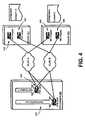
- FIG. 4is an exemplary embodiment of a network configuration illustrating a plurality of IPSI cards 510, 515 located in Integrated Trading System (ITS) chassis 505, may be coupled to a plurality of recorders 535, 545 at adapters 530, 535, 540, and 545. More specifically, a single IPSI card 510, 515 may have one or more contexts it serves. Similarly, a trading system may have one or more IPSI cards 510, 515 that are designated for providing data to recorders 550, 555.
- ITSIntegrated Trading System
- Each recorder 550, 555may be configured to determine which contexts to record. This is similar to instructions indicated which PCM32 spans that recorder is associated.
- the IP Voice Interface(such as may be provided by recording logic 812 from FIG. 8 ) may determine which contexts to connect the recorders 550, 555 for determining with which IPSI cards 510, 515 to communicate.
- the recorderscan record from any of three contexts, via two IPSI Cards, and two Recorders.
- Recorder 550may be configured to record Contexts 1 and 3.
- Recorder 2is configured to record context 2. Further, some embodiments may be configured to remove silent periods in a communication to minimize the resources required to store a recorded communication. Protocols such as VOX detect may be utilized.
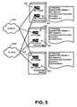
- FIG. 5is an exemplary embodiment illustrating a plurality of recorders coupled to a plurality of networks, similar to the diagram from FIG. 4 .
- VLANsVirtual Local Area Networks
- the recorder 650may include Network Interface Card (NIC) adapters 630, 633, which may be coupled to VLANs 602a and 602b, respectively.
- NIC adapters 635, 637may be coupled to VLANs 602a and 602b, respectively.
- NIC adapters 640, 643may be coupled to VLANs 602a, 602b, respectively.
- the recorder 650may be configured to record data from contexts 1, 2, and 3.
- the recorder 655may be configured to record data from contexts 4, 5, and 6.
- the recorder 657may be configured to record data as a spare recorder to provide failover protection for the recorders 650 and 655.
- the recorder 657may be configured to refrain from normal operation until receiving a signal that a recorder 650, 655 is unable (and/or inefficient) to record, this is a nonlimiting example. More specifically, in at least one exemplary embodiment, the recorders 650, 655, 657 may each be designated to one or more contexts for recording.
- the contexts related to the failed recordermay be automatically redistributed to the remaining recorders.
- the contextsmay be redistributed to the restored recorder.
- FIG. 6is an exemplary embodiment illustrating a customer center 730 and a recorder host 732, similar to the diagram from FIG. 5 .
- the customer center 730(which may include a British Telecom trading system and/or other customer center) may be configured to send IP infrastructure and/or other data to the recorder 732, which may include a network interface card 734 and an Al Logix PCM32 card 736.
- the network interface card 734may be configured to send data to a capture engine process block 738, which may include an IP interface library 740.
- the PCM32 card 736may be configured to send data to the capture engine process block 738, which may also include an IP interface library 742.
- the IP interface libraries 740, 742may be configured to send and/or receive data from main service code 744.
- the main service code 744may be configured to create a recorder configuration document 746.
- the IP Voice Interface Library 740, 742represents code developed by a hardware vendor to interface with an IP voice infrastructure.
- the main service code 744represents a capture engine code that loads the IP Voice interface library 740, 742 and uses the loaded data to obtain the voice data.
- the IP voice interface library 740may be configured to encapsulate the wire-protocol for IP voice transmission (PWE3, etc .).
- the IP voice interface library 470may also be configured to use configuration information supplied by the main service code 744.
- the IP voice interface library 740may also be configured to signal the main service code 744 via a callback when voice data is available.
- the main service code 744may be configured to load configuration information from the recorder 732 and configure the IP voice interface library 740 with that information. Additionally, depending on the particular exemplary embodiment, the main service code 744 may be configured to respond to available voice data by copying the data into a buffer (not shown) and processing. The main service code 744 may also be configured to respond to loss of a connection to the IP Voice infrastructure by signaling to standby recorders. The main service code 744 may be configured to communicate with other recorders to determine whether a standby recorder should take over recording duties.
- the IP voice interfacemay be a 32-bit Windows Dynamic Link Library (DLL) exposing a specified set of API functions. More specifically, the IP voice interface may be configured to provide an event callback interface and/or initialization/termination functionality.
- the event callback interfacemay be the primary interface used during recording. This interface may be configured to deliver voice packets and/or error, warning and status information for a recording.
- the IP voice interfacemay be configured to define the following callback API: void EventCallback (int channel, int eventCount, EventType [] event, void * parameter); Table 1 - Event/Callback Functionality Parameter Description Channel Indicates the virtual channel on which the event is appearing. This may be a mixed set of verts similar to a PCM32 channel. EventCount The number of events pointed to by event. This allows a multiple number of events to be delivered in the same callback to optimize performance. Event Array of events to be processed by the callback. Parameter A parameter defined by the client library. Separate values can be defined for each channel. This might be, for example, a pointer to an object containing state information for the channel.
- An event structuremay be utilized with the IP voice interface and may be configured to define at least one event type. More specifically, in at least one exemplary embodiment, the event structure may be represented as the following computer code:
- event typessuch as from Table 2, which may be provided in the IP voice interface, may be represented by the following: Table 3 - Event Types Event Type Description
- EVENT_BUFFER_READYIndicates a buffer of voice data is ready for the client to gather and process.
- Parameter 1contains the number of bytes available.
- EVENT_WARNING_PARTIAL_CONNECTION_LOSSIndicates one of the redundant connections is lost, but not all of them. Provided to allow the client to execute alarm operations.
- the context lostis identified by parameter 1.
- the network interface lostis identified by Parameter 2. This event may trigger after a Start Streaming API is called and after the implantation can determine that a connection is not available for a particular context.
- EVENT_ERROR_CONNECTION_LOSTIndicates all of the redundant connections are lost.
- the context lostis identified by parameter 1. This event will fire after the Start Streaming API is called as soon as the implantation can determine that a connection is not available for a particular context.
- EVENT_ERROR_OVERFLOWIndicates at least some voice data was lost because the client was not able to gather it before the buffer overlflowed.
- a RegisterCallback functionmay also be utilized and may be called by a client API to register a callback function for a given channel.
- a different callback functioncan be registered for each channel and each channel can be registered with a different client-defineable parameter. Additionally, the following code may be utilized to represent the registercallback function:
- RegisterCallback(int channel, CallbackFunctionTypecallback, void * parameter);
- Table 4 - RegisterCallback function Parameter Description ChannelIdentifies the virtual channel for which the callback function will be called. Can be 1 or 0 to indicate all channels. Callback Pointer to the callback function to be called for the specified channel. Parameter Pointer to client-definable data for the specified channel. May be passed back when the callback function is called.
- the GetBuffer functionmay also be utilized by the IP voice interface and may is called by the client API to gather voice data when it is available for processing. This function may be represented by the following code:
- the IP voice interfacemay utilize Initialization/Termination functions, which may be configured to initialize and terminate functionality inside the interface library. They may be available for the interface library to setup and tear down any necessary resources for use. It may be possible to initialize and shutdown the library any number of times during the same process. Similarly, it may also be possible to initialize the library any number of times without interrupting any functionality.
- the implementationmay be configured to count the number of InitializeLibrary and ShutdownLibrary calls so that only the first InitializeLibrary and last ShutdownLibrary will act upon resources used. This may be configured to enable the client to operate in a way that will ensure accidental calls will not interrupt functions of the interface.
- the following codemay be configured to trigger these functions:
- StartStreaming and StopStreaming functionsmay be utilized by the IP voice interface and may used to cause the interface to begin streaming data via the callback functions currently registered. These functions may also cause the warning and error callback functions to be called for the indicated context in the event that connection is lost. These functions may be represented by the following code:
- ContextsIdentifies the contexts (PWE3 stream of several virtual channels) to begin streaming on and reporting errors on.
- AdaptersIdentifies the network adapters to be used to connect to the IPSI cards.
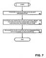
- FIG. 7is an exemplary embodiment of a process that may be utilized for recording communications data, such as in the customer center 105 from FIG. 1 .
- a recording hostcan receive communications data via an IP infrastructure (block 760).
- the recording hostcan provide an IP interface via an IP interface library, the IP interface library configured to receive configuration data from the main service code (block 762).
- the recording hostcan record at least a portion of the communications data according to the IP interface (block 764).
- FIG. 8is a schematic diagram illustrating an embodiment of a computer for implementing an interface.
- system 700includes a processor 802, memory 804, and one or more input and/or output (I/O) devices interface(s) 806 that are communicatively coupled via a local interface 808.
- the local interface 806can include, for example but not limited to, one or more buses or other wired or wireless connections.
- the local interfacemay have additional elements, which are omitted for simplicity, such as controllers, buffers (caches), drivers, repeaters, and receivers to enable communication.
- memory 804may also include recording logic 812, which may be configured to provide an IP interface, as discussed above, and/or perform other actions described above.
- the recording logic 812may one or more separate components, as illustrated in recording host 732 from FIG. 6 .
- the local interfacemay include address, control, and/or data connections to enable appropriate communications among the aforementioned components.
- the processormay be a hardware device for executing software, particularly software stored in memory.
- the memorycan include any one or combination of volatile memory elements (e.g ., random access memory (RAM, such as DRAM, SRAM, SDRAM, etc .)) and nonvolatile memory elements (e.g ., ROM, hard drive, tape, CDROM, etc .). Moreover, the memory may incorporate electronic, magnetic, optical, and/or other types of storage media. Note that the memory can have a distributed architecture, where various components are situated remote from one another, but can be accessed by the processor. Additionally, the memory includes an operating system 710, as well as instructions for implementing an interface. Exemplary embodiments of each of which are described above.
- volatile memory elementse.g ., random access memory (RAM, such as DRAM, SRAM, SDRAM, etc .)
- nonvolatile memory elementse.g ., ROM, hard drive, tape, CDROM, etc .
- the memorymay incorporate electronic, magnetic, optical, and/or other types of storage media. Note that the memory can have a distributed architecture, where various components are situated
- speech analyticsi.e., the analysis of recorded speech or real-time speech
- speech analyticscan be used to compare a recorded interaction to a script (e.g ., a script that the agent was to use during the interaction).
- speech analyticscan be used to measure how well agents adhere to scripts, identify which agents are "good" sales people and which ones need additional training. As such, speech analytics can be used to find agents who do not adhere to scripts.
- speech analyticscan measure script effectiveness, identify which scripts are effective and which are not, and find, for example, the section of a script that displeases or upsets customers (e.g., based on emotion detection).
- compliance with various policiescan be determined. Such may be in the case of, for example, the collections industry where it is a highly regulated business and agents must abide by many rules.
- the speech analytics of the present disclosuremay identify when agents are not adhering to their scripts and guidelines. This can potentially improve collection effectiveness and reduce corporate liability and risk.
- various types of recording componentscan be used to facilitate speech analytics.
- such recording componentscan perform one or more of various functions such as receiving, capturing, intercepting and tapping of data. This can involve the use of active and/or passive recording techniques, as well as the recording of voice and/or screen data.
- speech analyticscan be used in conjunction with such screen data (e.g ., screen data captured from an agent's workstation/PC) for evaluation, scoring, analysis, adherence and compliance purposes, for example.
- screen datae.g ., screen data captured from an agent's workstation/PC
- speech analyticscan be used in conjunction with such screen data (e.g ., screen data captured from an agent's workstation/PC) for evaluation, scoring, analysis, adherence and compliance purposes, for example.
- Such integrated functionalitycan improve the effectiveness and efficiency of, for example, quality assurance programs.
- the integrated functioncan help companies to locate appropriate calls (and related screen interactions) for quality monitoring and evaluation. This type of "precision" monitoring improves the effectiveness and productivity of quality assurance programs.
- speech analyticscan be used independently and/or in combination with other techniques for performing fraud detection. Specifically, some embodiments can involve identification of a speaker (e.g., a customer) and correlating this identification with other information to determine whether a fraudulent claim for example is being made. If such potential fraud is identified, some embodiments can provide an alert.
- the speech analytics of the present disclosuremay identify the emotions of callers. The identified emotions can be used In conjunction with identifying specific concepts to help companies spot either agents or callers/customers who are involved in fraudulent activities.
- At least one embodiment of an integrated workforce optimization platformintegrates: (1) Quality Monitoring/Call Recording - voice of the customer; the complete customer experience across multimedia touch points; (2) Workforce Management - strategic forecasting and scheduling that drives efficiency and adherence, aids in planning, and helps facilitate optimum staffing and service levels; (3) Performance Management - key performance indicators (KPIs) and scorecards that analyze and help identify synergies, opportunities and improvement areas; (4) e-Learning - training, new information and protocol disseminated to staff, leveraging best practice customer interactions and delivering learning to support development; (5) Analytics - deliver insights from customer interactions to drive business performance; (6) Coaching - feedback to promote efficient performance; and/or (7) Survey - receipt and review of customer feedback and analysis of interactions from customer perspective.
- KPIsKey performance indicators
- the integrated workforce optimization process and systemcan include planning and establishing goals - from both an enterprise and center perspective - to ensure alignment and objectives that complement and support one another.
- planningmay be complemented with forecasting and scheduling of the workforce to ensure optimum service levels.
- Recording and measuring performancemay also be utilized, leveraging quality monitoring/call recording to assess service quality and the customer experience.
- a surveycan be provided in order to obtain customer feedback regarding a customer's experience with the customer center.
- each blockcan be interpreted to represent a module, segment, or portion of code, which comprises one or more executable instructions for implementing the specified logical function(s).
- the functions noted in the blocksmay occur out of the order. For example, two blocks shown in succession may in fact be executed substantially concurrently or the blocks may sometimes be executed in the reverse order, depending upon the functionality involved.
- any of the programs listed hereincan include an ordered listing of executable instructions for implementing logical functions (such as depicted in the flowcharts), can be embodied in any computer-readable medium for use by or in connection with an instruction execution system, apparatus, or device, such as a computer-based system, processor-containing system, or other system that can fetch the instructions from the instruction execution system, apparatus, or device and execute the instructions.
- a "computer-readable medium”can be any means that can contain, store, communicate, propagate, or transport the program for use by or in connection with the instruction execution system, apparatus, or device.
- the computer readable mediumcan be, for example but not limited to, an electronic, magnetic, optical, electromagnetic, infrared, or semiconductor system, apparatus, or device. More specific examples (a nonexhaustive list) of the computer-readable medium could include an electrical connection (electronic) having one or more wires, a portable computer diskette (magnetic), a random access memory (RAM) (electronic), a read-only memory (ROM) (electronic), an erasable programmable read-only memory (EPROM or Flash memory) (electronic), an optical fiber (optical), and a portable compact disc read-only memory (CDROM) (optical).
- the scope of the certain embodiments of this disclosurecan include embodying the functionality described in logic embodied in hardware or software-configured mediums.
Landscapes
- Engineering & Computer Science (AREA)
- Signal Processing (AREA)
- Business, Economics & Management (AREA)
- Marketing (AREA)
- Computer Networks & Wireless Communication (AREA)
- Telephonic Communication Services (AREA)
- Communication Control (AREA)
Description
- This application relates to recording solutions. More specifically, this application relates to recording solutions in a communications network.
- Customer centers may record communications among employees and between employees and customers to monitor quality of performance, determine customer requests, and/or for other reasons. Some customer centers include recording components used for such recordings that are specific to certain types of communications, such as time division multiplexing (TDM) and Internet Protocol (IP). For example, a customer center that records TDM audio may include a TDM recorder. If that customer center records both TDM and IP communications data, the customer center also may also have an IP recorder that is separate and independent from the TDM recorder.
- In addition, if a customer center is configured to record agent desktop screen data, the customer center may utilize a screen capture recorder, which may be separate and independent from the TDM and IP recorders. In addition, some customer centers have both TDM and IP infrastructures associated with recording communications at the customer centers. However, there are various communications protocols available that can be implemented in both the TDM and IP infrastructures. If the customers centers change communications protocols, the customer centers may utilize different recording-related components associated with the changed protocol to implement the change, which may be expensive and time consuming. Additionally, oftentimes, customer centers desire an interface to facilitate recording of the communications data and/or the ability to change settings of the recording infrastructure.
WO 2007/007090 discloses a system for recording communications data wherein callback functionality is initiated by a telephone call to an endpoint to set up a call leg, where call legs are discrete elements of a call connection. - According to one aspect of the invention there is provided a method for recording communications data in accordance with events, comprising:
- receiving communications data associated with a communications session, the communications session facilitated in an Internet Protocol environment;
- characterized by providing an application programming interface that receives a channel identifier and the events associated with a channel identified by the channel identifier, the application programming interface facilitating recording of at least a portion of the communications session, the interface being facilitated in an Internet Protocol (IP) format, and initiating an event callback functionality to control recording of the communications data associated with the channel at a recorder in accordance with the events.
- According to another aspect of the invention there is provided a system for recording communications data in accordance with events, comprising: a receiving component configured to receive communications data associated with a communications session, the communications session facilitated in an Internet Protocol environment; a providing component configured to provide an Internet Protocol (IP) voice application programming interface for facilitating recording of at least a portion of the communications session, the interface being facilitated in an Internet Protocol format;
- and a recording component configured to record at least a portion of the communications data according to the interface, characterized in that the IP voice interface is configured to receive events associated with a channel and provide an event callback functionality to control initialization and termination of recording of the communications data based on the events associated with the channel.
- Other systems, methods, features, and/or advantages of this disclosure will be or may become apparent to one with skill in the art upon examination of the following drawings and detailed description. It is intended that all such additional systems, methods, features, and advantages be included within this description and be within the scope of the present disclosure.
- Many aspects of the disclosure can be better understood with reference to the following drawings. The components in the drawings are not necessarily to scale, emphasis instead being placed upon clearly illustrating the principles of the present disclosure. Moreover, in the drawings, like reference numerals designate corresponding parts throughout the several views. While several embodiments are described in connection with these drawings, there is no intent to limit the disclosure to the embodiment or embodiments disclosed herein. On the contrary, the intent is to cover all alternatives, modifications, and equivalents.
FIG. 1 is a schematic diagram of an embodiment of a system in which communications at a customer center can be recorded by a recording system.FIG. 2 is a schematic diagram of an embodiment of a communications network at a customer center, such as that shown inFIG. 1 .FIG. 3 is an exemplary embodiment of a megalink, illustrating components that may be utilized for recording in a communications network, which may include the customer center fromFIG. 1 .FIG. 4 is an exemplary embodiment illustrating a plurality recorders coupled to an Internet Protocol Switch Interface (IPSI) card, such as the IPSI card fromFIG. 3 .FIG. 5 is an exemplary embodiment illustrating a plurality of recorders coupled to a plurality of networks, similar to the diagram fromFIG. 4 .FIG. 6 is an exemplary embodiment illustrating a customer center and a recorder host, which may be configured to provide an IP voice interface, similar to the diagram fromFIG. 5 .FIG. 7 is an exemplary embodiment of a process that may be utilized for recording communications data, such as in the customer center fromFIG. 1 .- Disclosed herein are systems and methods for capturing communications data at a customer center and/or providing an IP voice interface. In particular, embodiments disclosed herein incorporate recording techniques that include at least one interface library that facilitates receiving and recording of communications data. The recording techniques can be deployed at a centralized location,e.g., within a company premises, and/or embedded into a network as a service on the network and/or as intelligence in the network infrastructure.
- Exemplary embodiments are first discussed with reference to the figures. Although these embodiments are described in detail, they are provided for purposes of illustration only and various modifications are feasible.
FIG. 1 is a schematic diagram of an embodiment of asystem 100 in which communications at a customer center can be recorded by arecording system 150. As indicated in the nonlimiting example ofFIG. 1 , thesystem 100 may include acustomer center premises 105 that includes a customercenter switching component 110,computing device 115, andcommunications devices customer center network 120. Thecommunications devices - Incoming communications from a
communications network 155 can be routed to theswitching component 110, which can route the communications to thecomputing device 115 and/orcommunications devices communication network 155 can be a Public Switch Telephony Network (PSTN) and/or IP-based network, among others. The incoming communications can include, but are not limited to, voice, text, video, and/or data, among others. Thecustomer center network 120 can include, but is not limited to, a wide area network (WAN), a local area network (LAN), a virtual private network (VPN) and/or the Internet. - The
switching component 110 may be operative to process the communications at thecustomer center 105 and transmit the communications to arecording system 150 via, for example, anIP infrastructure 140 and/or aTDM infrastructure 145, among others. Thecustomer center 105 is further described in relation toFIG. 2 . - The
IP infrastructure 140 of thecustomer center 105 can include, but is not limited to, a Pseudowire Emulation Edge to Edge (PWE3) protocol, Session initiation Protocol (SIP), and Real-Time Transport Protocol) (RTP), among others. The objective of PWE3 protocol is to supportmany Layer 1 andLayer 2 services over a common packet switched network (PSN) infrastructure. TheLayer 1 andLayer 2 services include, but are not limited to, frame relay, Ethernet, Asynchronous Transfer Mode (ATM), Synchronous Optical Network (SONET), and Time Division Multiplexing (TDM). The PWE3 protocol defines framework and architecture with particular requirements to satisfy the service-specific protocol that defines how eachLayer 1 orLayer 2 is encapsulated in PSN frames. Examples of PSN include, but are not limited to, MultiProtocol Label Switching (MPLS), Internet Protocol (IP) such as RTP, IPv4, or IPv6, andLayer 2 Tunneling Protocol (L2TP). The PWE 3 protocol also defines control protocol to establish connectivity across the PSN. TDM infrastructure 145 includes a circuit mode communication with a fixed number of channels and constant bandwidth per channel. In circuit switched networks, such as the Public Switched Telephone Network (PSTN), among others, multiple subscribers' calls may be transmitted along the same transmission medium. To accomplish this, network designers make use of TDM. TDM allows switches to create channels, also known as tributaries, within a transmission stream. A standard voice signal generally has a data bit rate of 64 kbit/s, determined using Nyquist's Sampling Criterion. TDM takes frames of the voice signals and multiplexes them into a TDM frame, which runs at a higher bandwidth.FIG. 2 is a schematic diagram of an embodiment of a communications network at acustomer center 205. Thecustomer center 205 includes atelephony system 103 and a Voice over IP (VoIP)system 106. Thetelephony system 103 may be configured to receive communications data by way of a switch 109 (or automatic call distributor "ACD") vialine 113. Theswitch 109 can distribute incoming communications data to one ormore communications devices punchdown block 126. Thecommunications devices desktops communications devices desktops corporate LAN 143, which enables the desktops to communicate with each other and/or with other computers outside thecustomer center 205. Thetelephony system 103 may be coupled to aPSTN 146 and can transmit outgoing communications data using thePSTN 146.- The Voice over Internet Protocol (VoIP)
system 106 can be connected to thePSTN 146. TheVoIP system 106 may be configured to receive and transmit communications data via gateway/router 156. If thegateway 156 receives the communications data from thePSTN 146, thegateway 156 converts the communications data to digital communications data. Similarly, thegateway 156 can receive digital communications data from an Internet Protocol Wide Area Network (IP WAN) 153. In either or both situations, thegateway 156 may be configured to send the digital communications data to a VolP network/switch 159, which distributes the signal toVolP communications devices - A
recording system 203 can be a single recording server or a cluster of recording servers, for example. Therecording system 203 can receive various types of communication signals from the communication network and store the communication signals in an allocated resource (not shown). Therecording system 203 can receive and store, for example,data 206 from theagent desktops corporate LAN 143;audio data 209 from thepunchdown block 126 by way of extension taps;service observation data 213 from the switch/ACD 109;communications data 216 between theswitch 109 andPSTN 146 by way of TDM trunck taps;IP data 223 between thegateway 156 and the VolP Network/switch 159 by way of IP trunk taps;IP data 226 from the switch by way of IP extension taps;IP data 229 fromIP communications devices media data 239 from themedia application server 236, andvideo conference data 233 from theIP communications device 169. Similarly, therecording system 203 can receive and store communication signals in either 32-bit or 128-bit scheme, or both. - The
recording system 203 can further receive various types of externalcontact center events 219 from themultiple servers 173, 176, 179. Therecording system 203 enables continued use of themultiple servers 173, 176, 179 by receiving the various types of externalcontact center events 219 and determines whether to record communications data based on the received events. Similarly, therecording system 203 can receive and store data from media servers with recorder capabilities ("media server/recorder"). Therecording system 203 may include one or more interfaces that communicate with the media servers/recorder to manage the data stored in the media server/recorder, such as archive, data management, and search and mine. In other words, therecording system 203 can integrate with the media server/recorder at a cluster of subsystems. Additionally or alternatively, therecording system 203 receives and stores data stored in the media server/recorder. FIG. 3 is an exemplary embodiment of a megalink, illustrating components that may be utilized for recording in a communications network, which may include thecustomer center 105 fromFIG. 1 . As illustrated in the nonlimiting example ofFIG. 3 , one or more Internet Protocol Switch Interface (IPSI)cards 270 may be utilized to connect to one or more recorders (not shown in this nonlimiting example). TheIPSI cards 270 may or may not be connected to IP turrets and/or other communications devices, as well. Similar to a TDM configuration, the verts (verticals) 272 of the trading system may be mixed and organized into one ormore contexts 274. Acontext 274 may be similar to a single Pulse Code Modulation 32 (PCM32)span 276, which may be provided by a Universal Switch Interface (USI)PCM32 card 280. So each context may include up to 32 multiplexedchannels 278 on it.FIG. 3 illustrates how theIPSI Cards 270 are similar to the USI (PCM32)Cards 280 in that they may both be configured to transmit a mixed set ofVerts 272 over a wire protocol.FIG. 4 is an exemplary embodiment of a network configuration illustrating a plurality ofIPSI cards recorders adapters single IPSI card more IPSI cards recorders - Each
recorder recording logic 812 fromFIG. 8 ) may determine which contexts to connect therecorders IPSI cards FIG. 5 , the recorders can record from any of three contexts, via two IPSI Cards, and two Recorders.Recorder 550 may be configured to recordContexts Recorder 2 is configured to recordcontext 2. Further, some embodiments may be configured to remove silent periods in a communication to minimize the resources required to store a recorded communication. Protocols such as VOX detect may be utilized. FIG. 5 is an exemplary embodiment illustrating a plurality of recorders coupled to a plurality of networks, similar to the diagram fromFIG. 4 . As illustrated in the nonlimiting example, Virtual Local Area Networks (VLANs) 602a, 602b may be coupled to a plurality ofrecorders adapters VLANs NIC adapters VLANs NIC adapters VLANs - As illustrated, the recorder 650 may be configured to record data from
contexts recorder 655 may be configured to record data fromcontexts recorder 657 may be configured to record data as a spare recorder to provide failover protection for therecorders 650 and 655. Similarly, while in some embodiments, therecorder 657 may be configured to refrain from normal operation until receiving a signal that arecorder 650, 655 is unable (and/or inefficient) to record, this is a nonlimiting example. More specifically, in at least one exemplary embodiment, therecorders FIG. 6 is an exemplary embodiment illustrating acustomer center 730 and arecorder host 732, similar to the diagram fromFIG. 5 . As illustrated in the nonlimiting example ofFIG. 6 , the customer center 730 (which may include a British Telecom trading system and/or other customer center) may be configured to send IP infrastructure and/or other data to therecorder 732, which may include anetwork interface card 734 and an AlLogix PCM32 card 736. Thenetwork interface card 734 may be configured to send data to a captureengine process block 738, which may include anIP interface library 740. Similarly, thePCM32 card 736 may be configured to send data to the captureengine process block 738, which may also include anIP interface library 742. TheIP interface libraries main service code 744. Themain service code 744 may be configured to create arecorder configuration document 746.- More specifically, in operation, the IP
Voice Interface Library main service code 744 represents a capture engine code that loads the IPVoice interface library - The IP
voice interface library 740 may be configured to encapsulate the wire-protocol for IP voice transmission (PWE3,etc.). The IP voice interface library 470 may also be configured to use configuration information supplied by themain service code 744. The IPvoice interface library 740 may also be configured to signal themain service code 744 via a callback when voice data is available. - Similarly, the
main service code 744 may be configured to load configuration information from therecorder 732 and configure the IPvoice interface library 740 with that information. Additionally, depending on the particular exemplary embodiment, themain service code 744 may be configured to respond to available voice data by copying the data into a buffer (not shown) and processing. Themain service code 744 may also be configured to respond to loss of a connection to the IP Voice infrastructure by signaling to standby recorders. Themain service code 744 may be configured to communicate with other recorders to determine whether a standby recorder should take over recording duties. - In at least one exemplary embodiment, the IP voice interface may be a 32-bit Windows Dynamic Link Library (DLL) exposing a specified set of API functions. More specifically, the IP voice interface may be configured to provide an event callback interface and/or initialization/termination functionality. The event callback interface may be the primary interface used during recording. This interface may be configured to deliver voice packets and/or error, warning and status information for a recording.
- With regard to the event/callback functionality, the IP voice interface may be configured to define the following callback API: void EventCallback (int channel, int eventCount, EventType [] event, void * parameter);
Table 1 - Event/Callback Functionality Parameter Description Channel Indicates the virtual channel on which the event is appearing. This may be a mixed set of verts similar to a PCM32 channel. EventCount The number of events pointed to by event. This allows a multiple number of events to be delivered in the same callback to optimize performance. Event Array of events to be processed by the callback. Parameter A parameter defined by the client library. Separate values can be defined for each channel. This might be, for example, a pointer to an object containing state information for the channel. - An event structure may be utilized with the IP voice interface and may be configured to define at least one event type. More specifically, in at least one exemplary embodiment, the event structure may be represented as the following computer code:
struct Event { int eventType; long parameter1; long parameter2; };| Field | Description |
| EventType | Enumeration of event types. |
| Parameter1 | Event-specific parameter for the event. |
| Parameter2 | Event-specific parameter for the event. |
| Event Type | Description |
| EVENT_BUFFER_READY | Indicates a buffer of voice data is ready for the client to gather and process. |
| EVENT_WARNING_PARTIAL_CONNECTION_LOSS | Indicates one of the redundant connections is lost, but not all of them. Provided to allow the client to execute alarm operations. |
| The context lost is identified by | |
| The network interface lost is identified by | |
| This event may trigger after a Start Streaming API is called and after the implantation can determine that a connection is not available for a particular context. | |
| EVENT_ERROR_CONNECTION_LOST | Indicates all of the redundant connections are lost. |
| The context lost is identified by | |
| This event will fire after the Start Streaming API is called as soon as the implantation can determine that a connection is not available for a particular context. | |
| EVENT_ERROR_OVERFLOW | Indicates at least some voice data was lost because the client was not able to gather it before the buffer overlflowed. |
| Parameter | Description |
| Channel | Identifies the virtual channel for which the callback function will be called. Can be 1 or 0 to indicate all channels. |
| Callback | Pointer to the callback function to be called for the specified channel. |
| Parameter | Pointer to client-definable data for the specified channel. May be passed back when the callback function is called. |
| Parameter | Description |
| Channel | Indicates the virtual channel to obtain data from. |
| Buffer | Pointer to buffer to place data in. |
| BufferSize | Size of buffer available to place data in. |
| Return Value | Number of bytes placed in the buffer by the interface. |
| Parameter | Description |
| BufferMillisecondsPerChannel | Controls the size of the buffer used to hold voice data for each virtual channel. Should be larger than the callback period. |
| CallbackPeriod | Controls the frequency of callbacks. For example setting 1000 ms would imply one callback per second for each channel. |
| Parameter | Description |
| Contexts | Identifies the contexts (PWE3 stream of several virtual channels) to begin streaming on and reporting errors on. |
| Adapters | Identifies the network adapters to be used to connect to the IPSI cards. |
Claims (12)
- A method for recording communications data in accordance with events, comprising:receiving communications data associated with a communications session, the communications session facilitated in an Internet Protocol environmentcharacterized by:providing an application programming interface that receives a channel identifier and the events associated with a channel identified by the channel identifier, the application programming interface facilitating recording of at least a portion of the communications session, the interface being facilitated in an Internet Protocol (IP) format; andinitiating an event callback functionality to control recording of the communications data associated with the channel at a recorder in accordance with the events.
- The method of claim 1, wherein the event callback functionally is configured to facilitate delivery of voice packets, error, warning and status information for a recording.
- The method of claim 1, wherein the interface includes initialization and termination functionality, the initialization and termination functionality configured to setup at least one recording resource during use.
- The method of claim 1, further comprising:utilizing a failover recorder in response to a determination that a primary recorder has failed, wherein the primary recorder and the failover recorder are configured to receive the communications data;determining whether the primary recorder has failed; andproviding, via the interface, an indication that the primary recorder has failed.
- The method of claim 4, wherein the failover recorder is configured for normal operation prior to the determination that the primary recorder has failed.
- The method of claim 1, wherein the interface is configured to operate with at least one of the following: Pseudowire Emulation Edge to Edge (PWE3) protocol, Session Initiation Protocol (SIP), and Real-Time Protocol (RTP).
- The method of claim 1, further comprising utilizing Voice Operated Exchange (VOX) detect to remove silent periods.
- A system for recording communications data in accordance with events, comprising:a receiving component (103, 106) configured to receive communications data associated with a communications session, the communications session facilitated in an Internet Protocol environment;a providing component (505) configured to provide an Internet Protocol (IP) voice application programming interface for facilitating recording of at least a portion of the communications session, the interface being facilitated in an Internet Protocol format; anda recording component (650, 655, 657) configured to record at least a portion of the communications data according to the interface,characterized in that:the IP voice interface is configured to receive events associated with a channel and provide an event callback functionality to control initialization and termination of recording of the communications data based on the events associated with the channel.
- The system of claim 8, wherein the initialization and termination functionality is configured to initialize without interrupting the communications session.
- The system of claim 8, wherein the system is configured for the recording component to record IP based data and Time Division Multiplexing (TDM) based data.
- The system of claim 8, wherein the communications data is received at a first recorder (650,655) and a second recorder (657), the second recorder (657) configured to provide failover recording protection.
- The system of claim 11, further comprising:a determining component configured to determine whether the first recorder has failed; anda second providing component configured to provide, via the interface, an indication that the first recorder has failed.
Applications Claiming Priority (2)
| Application Number | Priority Date | Filing Date | Title |
|---|---|---|---|
| US95267507P | 2007-07-30 | 2007-07-30 | |
| US12/118,792US8724521B2 (en) | 2007-07-30 | 2008-05-12 | Systems and methods of recording solution interface |
Publications (3)
| Publication Number | Publication Date |
|---|---|
| EP2020812A2 EP2020812A2 (en) | 2009-02-04 |
| EP2020812A3 EP2020812A3 (en) | 2010-11-10 |
| EP2020812B1true EP2020812B1 (en) | 2012-03-07 |
Family
ID=39642875
Family Applications (1)
| Application Number | Title | Priority Date | Filing Date |
|---|---|---|---|
| EP08251691AActiveEP2020812B1 (en) | 2007-07-30 | 2008-05-14 | Systems and methods of recording solution interface |
Country Status (3)
| Country | Link |
|---|---|
| US (2) | US8724521B2 (en) |
| EP (1) | EP2020812B1 (en) |
| CA (1) | CA2628406A1 (en) |
Families Citing this family (4)
| Publication number | Priority date | Publication date | Assignee | Title |
|---|---|---|---|---|
| US8724521B2 (en)* | 2007-07-30 | 2014-05-13 | Verint Americas Inc. | Systems and methods of recording solution interface |
| US9369570B1 (en)* | 2015-05-18 | 2016-06-14 | Nice-Systems Ltd | Concurrent recordings of telephonic interactions |
| US10182146B2 (en) | 2016-08-22 | 2019-01-15 | Nice Ltd. | System and method for dynamic redundant call recording |
| US11475112B1 (en)* | 2016-09-12 | 2022-10-18 | Verint Americas Inc. | Virtual communications identification system with integral archiving protocol |
Family Cites Families (61)
| Publication number | Priority date | Publication date | Assignee | Title |
|---|---|---|---|---|
| US4761807A (en)* | 1982-09-29 | 1988-08-02 | Vmx, Inc. | Electronic audio communications system with voice authentication features |
| JPH01160247A (en)* | 1987-12-17 | 1989-06-23 | Nec Corp | Telephone system with external line automatic redial function |
| CA2123924A1 (en)* | 1993-06-02 | 1994-12-03 | Charles Douglas Blewett | Specifying contexts in callback style programming |
| US5946375A (en)* | 1993-09-22 | 1999-08-31 | Teknekron Infoswitch Corporation | Method and system for monitoring call center service representatives |
| US5825771A (en)* | 1994-11-10 | 1998-10-20 | Vocaltec Ltd. | Audio transceiver |
| US20030191719A1 (en)* | 1995-02-13 | 2003-10-09 | Intertrust Technologies Corp. | Systems and methods for secure transaction management and electronic rights protection |
| US6343086B1 (en)* | 1996-09-09 | 2002-01-29 | Natural Microsystems Corporation | Global packet-switched computer network telephony server |
| GB9620082D0 (en)* | 1996-09-26 | 1996-11-13 | Eyretel Ltd | Signal monitoring apparatus |
| US5867494A (en)* | 1996-11-18 | 1999-02-02 | Mci Communication Corporation | System, method and article of manufacture with integrated video conferencing billing in a communication system architecture |
| US6335927B1 (en)* | 1996-11-18 | 2002-01-01 | Mci Communications Corporation | System and method for providing requested quality of service in a hybrid network |
| US6731625B1 (en)* | 1997-02-10 | 2004-05-04 | Mci Communications Corporation | System, method and article of manufacture for a call back architecture in a hybrid network with support for internet telephony |
| US6614781B1 (en)* | 1998-11-20 | 2003-09-02 | Level 3 Communications, Inc. | Voice over data telecommunications network architecture |
| US6775372B1 (en)* | 1999-06-02 | 2004-08-10 | Dictaphone Corporation | System and method for multi-stage data logging |
| EP1130892A3 (en)* | 2000-03-01 | 2002-01-02 | Siemens Aktiengesellschaft | Recording of telephone calls by a central voice storage device |
| US6470077B1 (en)* | 2000-03-13 | 2002-10-22 | Avaya Technology Corp. | Apparatus and method for storage and accelerated playback of voice samples in a call center |
| US7286652B1 (en)* | 2000-05-31 | 2007-10-23 | 3Com Corporation | Four channel audio recording in a packet based network |
| US6795868B1 (en)* | 2000-08-31 | 2004-09-21 | Data Junction Corp. | System and method for event-driven data transformation |
| US7092506B1 (en)* | 2000-10-23 | 2006-08-15 | Verizon Corporate Services Group Inc. | Systems and methods for providing audio information to service agents |
| US6751297B2 (en) | 2000-12-11 | 2004-06-15 | Comverse Infosys Inc. | Method and system for multimedia network based data acquisition, recording and distribution |
| US6917625B1 (en)* | 2001-01-16 | 2005-07-12 | At&T Corp. | Intelligent peripheral concentrator |
| US7340714B2 (en)* | 2001-10-18 | 2008-03-04 | Bea Systems, Inc. | System and method for using web services with an enterprise system |
| US7644136B2 (en)* | 2001-11-28 | 2010-01-05 | Interactive Content Engines, Llc. | Virtual file system |
| US7023979B1 (en)* | 2002-03-07 | 2006-04-04 | Wai Wu | Telephony control system with intelligent call routing |
| US7254109B2 (en)* | 2002-07-12 | 2007-08-07 | Baypackets, Inc. | Fault tolerant correlation engine method and system for telecommunications networks |
| US7535993B2 (en)* | 2003-04-21 | 2009-05-19 | Alcatel-Lucent Usa Inc. | Call control component employment of one or more criteria for internet protocol call selection for eavesdrop component monitoring |
| US7155641B2 (en)* | 2003-05-15 | 2006-12-26 | Microsoft Corporation | System and method for monitoring the performance of a server |
| US7027463B2 (en)* | 2003-07-11 | 2006-04-11 | Sonolink Communications Systems, Llc | System and method for multi-tiered rule filtering |
| US20050058313A1 (en)* | 2003-09-11 | 2005-03-17 | Victorian Thomas A. | External ear canal voice detection |
| US20080028096A1 (en)* | 2003-10-21 | 2008-01-31 | Henderson Alex E | Transporting fibre channel over ethernet |
| US20050108593A1 (en) | 2003-11-14 | 2005-05-19 | Dell Products L.P. | Cluster failover from physical node to virtual node |
| BRPI0318608B1 (en)* | 2003-11-17 | 2017-04-11 | Telecom Italia Spa | architecture and method for monitoring quality of service in a telecommunication network and telecommunication network |
| US7039661B1 (en)* | 2003-12-29 | 2006-05-02 | Veritas Operating Corporation | Coordinated dirty block tracking |
| KR20050070722A (en)* | 2003-12-30 | 2005-07-07 | 삼성전자주식회사 | System and method for processing call |
| TWI263915B (en)* | 2004-04-02 | 2006-10-11 | Hon Hai Prec Ind Co Ltd | System and method for logging event of telecommunications devices |
| US7796169B2 (en)* | 2004-04-20 | 2010-09-14 | Canon Kabushiki Kaisha | Image processing apparatus for correcting captured image |
| US7523343B2 (en)* | 2004-04-30 | 2009-04-21 | Microsoft Corporation | Real-time file system repairs |
| US7564846B2 (en)* | 2004-08-30 | 2009-07-21 | Dezonno Anthony J | Method of collecting communication system information |
| US7256816B2 (en)* | 2004-10-25 | 2007-08-14 | 3V Technologies Incorporated | Systems and processes for scheduling and conducting audio/video communications |
| US7733822B2 (en)* | 2004-11-30 | 2010-06-08 | Sanjay M. Gidwani | Distributed disparate wireless switching network |
| US7711978B1 (en)* | 2004-12-30 | 2010-05-04 | Symantec Operating Corporation | Proactive utilization of fabric events in a network virtualization environment |
| US7930323B2 (en)* | 2004-12-30 | 2011-04-19 | Sap Ag | Method for reallocating table formats in real-time |
| US7787974B2 (en) | 2005-01-05 | 2010-08-31 | Verint Americas Inc. | Independent source recording |
| GB0511920D0 (en) | 2005-06-11 | 2005-07-20 | Ibm | Method and architecture for processing rtp packets |
| GB2428347A (en)* | 2005-07-09 | 2007-01-24 | Ring2 Comm Ltd | Recording telephone conversations in a conference call environment |
| US7587507B2 (en) | 2005-07-22 | 2009-09-08 | Microsoft Corporation | Media recording functions in a streaming media server |
| US7558382B2 (en)* | 2005-11-30 | 2009-07-07 | Teletech Holdings, Inc. | Monitoring service personnel |
| US20070171898A1 (en)* | 2005-11-29 | 2007-07-26 | Salva Paul D | System and method for establishing universal real time protocol bridging |
| US7761591B2 (en)* | 2005-12-16 | 2010-07-20 | Jean A. Graham | Central work-product management system for coordinated collaboration with remote users |
| US8112298B2 (en) | 2006-02-22 | 2012-02-07 | Verint Americas, Inc. | Systems and methods for workforce optimization |
| US20070201502A1 (en)* | 2006-02-28 | 2007-08-30 | Maven Networks, Inc. | Systems and methods for controlling the delivery behavior of downloaded content |
| US7633930B2 (en)* | 2006-03-31 | 2009-12-15 | Verint Americas Inc. | Systems and methods for capturing multimedia communication signals |
| US8953756B2 (en) | 2006-07-10 | 2015-02-10 | International Business Machines Corporation | Checking for permission to record VoIP messages |
| US7548609B2 (en)* | 2006-09-07 | 2009-06-16 | Cti Group (Holding), Inc. | Process for scalable conversation recording |
| US7848937B2 (en) | 2006-09-08 | 2010-12-07 | American Well Corporation | Connecting consumers with service providers |
| US7570755B2 (en)* | 2006-09-29 | 2009-08-04 | Verint Americas Inc. | Routine communication sessions for recording |
| US20080082366A1 (en)* | 2006-10-02 | 2008-04-03 | Siemens Medical Solutions Usa, Inc. | Automated Medical Treatment Order Processing System |
| EP2119108B1 (en)* | 2007-03-05 | 2018-10-24 | Calabrio, Inc. | Monitoring quality of customer service in customer/agent calls over a voip network |
| US9424581B2 (en)* | 2007-04-10 | 2016-08-23 | Yellowpages.Com Llc | Systems and methods to facilitate real time communications and commerce via answers to questions |
| US20080298253A1 (en) | 2007-05-30 | 2008-12-04 | Nortel Networks Limited | Managing Recordings of Communications Sessions |
| US8724521B2 (en)* | 2007-07-30 | 2014-05-13 | Verint Americas Inc. | Systems and methods of recording solution interface |
| US8132089B1 (en)* | 2008-05-02 | 2012-03-06 | Verint Americas, Inc. | Error checking at the re-sequencing stage |
- 2008
- 2008-05-12USUS12/118,792patent/US8724521B2/enactiveActive
- 2008-05-14CACA002628406Apatent/CA2628406A1/ennot_activeAbandoned
- 2008-05-14EPEP08251691Apatent/EP2020812B1/enactiveActive
- 2014
- 2014-05-12USUS14/275,773patent/US9363369B2/enactiveActive
Also Published As
| Publication number | Publication date |
|---|---|
| EP2020812A2 (en) | 2009-02-04 |
| CA2628406A1 (en) | 2008-07-22 |
| US8724521B2 (en) | 2014-05-13 |
| US9363369B2 (en) | 2016-06-07 |
| US20140341360A1 (en) | 2014-11-20 |
| US20090034436A1 (en) | 2009-02-05 |
| EP2020812A3 (en) | 2010-11-10 |
Similar Documents
| Publication | Publication Date | Title |
|---|---|---|
| US7633930B2 (en) | Systems and methods for capturing multimedia communication signals | |
| US10289974B1 (en) | Establishing a target handle time for a communication in a contact center | |
| US8503313B1 (en) | Method and apparatus for detecting a network impairment using call detail records | |
| US8442033B2 (en) | Distributed voice over internet protocol recording | |
| US8379835B1 (en) | Systems and methods for endpoint recording using recorders | |
| US20080080685A1 (en) | Systems and Methods for Recording in a Contact Center Environment | |
| US9854097B2 (en) | Configuring contact center components for real time speech analytics | |
| US8396192B2 (en) | Desktop recording architecture for recording call sessions over a telephony network | |
| US20070297578A1 (en) | Hybrid recording of communications | |
| US20080301282A1 (en) | Systems and Methods for Storing Interaction Data | |
| US7369509B2 (en) | System and method for facilitating network troubleshooting | |
| US9363369B2 (en) | Systems and methods of recording solution interface | |
| US9647907B1 (en) | System, method, and computer-readable medium for diagnosing a conference call | |
| US8804539B2 (en) | Method and apparatus for detecting service disruptions in a packet network | |
| US8908557B2 (en) | Method and apparatus for monitoring a packet network | |
| US7995612B2 (en) | Systems and methods for capturing communication signals [32-bit or 128-bit addresses] | |
| EP2028831A2 (en) | Systems and methods for multi-stream recording | |
| CN110475113B (en) | Monitoring equipment fault processing method and device based on video network | |
| US20070237525A1 (en) | Systems and methods for modular capturing various communication signals | |
| US20080137814A1 (en) | Systems and Methods for Replaying Recorded Data | |
| US8094787B2 (en) | Method and system for utilizing information for efficient recording solutions in a complex multi-media recording environment | |
| KR100954515B1 (en) | Telephone consultation recording and playback device | |
| US8437465B1 (en) | Systems and methods for capturing communications data | |
| US20080008296A1 (en) | Data Capture in a Distributed Network | |
| US20090213742A1 (en) | Telephone Communication Monitoring Device and Method |
Legal Events
| Date | Code | Title | Description |
|---|---|---|---|
| PUAI | Public reference made under article 153(3) epc to a published international application that has entered the european phase | Free format text:ORIGINAL CODE: 0009012 | |
| AK | Designated contracting states | Kind code of ref document:A2 Designated state(s):AT BE BG CH CY CZ DE DK EE ES FI FR GB GR HR HU IE IS IT LI LT LU LV MC MT NL NO PL PT RO SE SI SK TR | |
| AX | Request for extension of the european patent | Extension state:AL BA MK RS | |
| PUAL | Search report despatched | Free format text:ORIGINAL CODE: 0009013 | |
| AK | Designated contracting states | Kind code of ref document:A3 Designated state(s):AT BE BG CH CY CZ DE DK EE ES FI FR GB GR HR HU IE IS IT LI LT LU LV MC MT NL NO PL PT RO SE SI SK TR | |
| AX | Request for extension of the european patent | Extension state:AL BA MK RS | |
| 17P | Request for examination filed | Effective date:20110509 | |
| AKX | Designation fees paid | Designated state(s):DE FR GB | |
| RIC1 | Information provided on ipc code assigned before grant | Ipc:H04M 1/656 20060101ALI20110725BHEP Ipc:H04L 12/26 20060101ALI20110725BHEP Ipc:H04M 3/50 20060101ALI20110725BHEP Ipc:H04M 3/42 20060101AFI20110725BHEP | |
| GRAP | Despatch of communication of intention to grant a patent | Free format text:ORIGINAL CODE: EPIDOSNIGR1 | |
| GRAS | Grant fee paid | Free format text:ORIGINAL CODE: EPIDOSNIGR3 | |
| GRAA | (expected) grant | Free format text:ORIGINAL CODE: 0009210 | |
| AK | Designated contracting states | Kind code of ref document:B1 Designated state(s):DE FR GB | |
| REG | Reference to a national code | Ref country code:GB Ref legal event code:FG4D | |
| REG | Reference to a national code | Ref country code:DE Ref legal event code:R096 Ref document number:602008013912 Country of ref document:DE Effective date:20120503 | |
| PLBE | No opposition filed within time limit | Free format text:ORIGINAL CODE: 0009261 | |
| STAA | Information on the status of an ep patent application or granted ep patent | Free format text:STATUS: NO OPPOSITION FILED WITHIN TIME LIMIT | |
| 26N | No opposition filed | Effective date:20121210 | |
| REG | Reference to a national code | Ref country code:DE Ref legal event code:R097 Ref document number:602008013912 Country of ref document:DE Effective date:20121210 | |
| REG | Reference to a national code | Ref country code:FR Ref legal event code:PLFP Year of fee payment:9 | |
| REG | Reference to a national code | Ref country code:FR Ref legal event code:PLFP Year of fee payment:10 | |
| REG | Reference to a national code | Ref country code:FR Ref legal event code:PLFP Year of fee payment:11 | |
| P01 | Opt-out of the competence of the unified patent court (upc) registered | Free format text:CASE NUMBER: UPC_APP_327445/2023 Effective date:20230524 | |
| PGFP | Annual fee paid to national office [announced via postgrant information from national office to epo] | Ref country code:FR Payment date:20250310 Year of fee payment:18 | |
| PGFP | Annual fee paid to national office [announced via postgrant information from national office to epo] | Ref country code:GB Payment date:20250320 Year of fee payment:18 | |
| PGFP | Annual fee paid to national office [announced via postgrant information from national office to epo] | Ref country code:DE Payment date:20250319 Year of fee payment:18 |