EP2020265A1 - Stent coating device - Google Patents
Stent coating deviceDownload PDFInfo
- Publication number
- EP2020265A1 EP2020265A1EP08019305AEP08019305AEP2020265A1EP 2020265 A1EP2020265 A1EP 2020265A1EP 08019305 AEP08019305 AEP 08019305AEP 08019305 AEP08019305 AEP 08019305AEP 2020265 A1EP2020265 A1EP 2020265A1
- Authority
- EP
- European Patent Office
- Prior art keywords
- coating
- stent
- applicator
- deployed
- coating applicator
- Prior art date
- Legal status (The legal status is an assumption and is not a legal conclusion. Google has not performed a legal analysis and makes no representation as to the accuracy of the status listed.)
- Granted
Links
Images


Classifications
- B—PERFORMING OPERATIONS; TRANSPORTING
- B05—SPRAYING OR ATOMISING IN GENERAL; APPLYING FLUENT MATERIALS TO SURFACES, IN GENERAL
- B05B—SPRAYING APPARATUS; ATOMISING APPARATUS; NOZZLES
- B05B12/00—Arrangements for controlling delivery; Arrangements for controlling the spray area
- B05B12/08—Arrangements for controlling delivery; Arrangements for controlling the spray area responsive to condition of liquid or other fluent material to be discharged, of ambient medium or of target ; responsive to condition of spray devices or of supply means, e.g. pipes, pumps or their drive means
- B05B12/12—Arrangements for controlling delivery; Arrangements for controlling the spray area responsive to condition of liquid or other fluent material to be discharged, of ambient medium or of target ; responsive to condition of spray devices or of supply means, e.g. pipes, pumps or their drive means responsive to conditions of ambient medium or target, e.g. humidity, temperature position or movement of the target relative to the spray apparatus
- B—PERFORMING OPERATIONS; TRANSPORTING
- B05—SPRAYING OR ATOMISING IN GENERAL; APPLYING FLUENT MATERIALS TO SURFACES, IN GENERAL
- B05B—SPRAYING APPARATUS; ATOMISING APPARATUS; NOZZLES
- B05B13/00—Machines or plants for applying liquids or other fluent materials to surfaces of objects or other work by spraying, not covered by groups B05B1/00 - B05B11/00
- B05B13/02—Means for supporting work; Arrangement or mounting of spray heads; Adaptation or arrangement of means for feeding work
- B05B13/04—Means for supporting work; Arrangement or mounting of spray heads; Adaptation or arrangement of means for feeding work the spray heads being moved during spraying operation
- B05B13/0442—Installation or apparatus for applying liquid or other fluent material to separate articles rotated during spraying operation
- B—PERFORMING OPERATIONS; TRANSPORTING
- B05—SPRAYING OR ATOMISING IN GENERAL; APPLYING FLUENT MATERIALS TO SURFACES, IN GENERAL
- B05C—APPARATUS FOR APPLYING FLUENT MATERIALS TO SURFACES, IN GENERAL
- B05C5/00—Apparatus in which liquid or other fluent material is projected, poured or allowed to flow on to the surface of the work
- B05C5/02—Apparatus in which liquid or other fluent material is projected, poured or allowed to flow on to the surface of the work the liquid or other fluent material being discharged through an outlet orifice by pressure, e.g. from an outlet device in contact or almost in contact, with the work
- B05C5/0208—Apparatus in which liquid or other fluent material is projected, poured or allowed to flow on to the surface of the work the liquid or other fluent material being discharged through an outlet orifice by pressure, e.g. from an outlet device in contact or almost in contact, with the work for applying liquid or other fluent material to separate articles
- B05C5/0212—Apparatus in which liquid or other fluent material is projected, poured or allowed to flow on to the surface of the work the liquid or other fluent material being discharged through an outlet orifice by pressure, e.g. from an outlet device in contact or almost in contact, with the work for applying liquid or other fluent material to separate articles only at particular parts of the articles
- B05C5/0216—Apparatus in which liquid or other fluent material is projected, poured or allowed to flow on to the surface of the work the liquid or other fluent material being discharged through an outlet orifice by pressure, e.g. from an outlet device in contact or almost in contact, with the work for applying liquid or other fluent material to separate articles only at particular parts of the articles by relative movement of article and outlet according to a predetermined path
Definitions
- the present inventionrelates to the coating of medical devices intended for in vivo deployment and, in particular, it concerns a method and device, which is suitable for use in an operating theater just prior to implantation, for selectively applying a medical coating to an implantable medical device, for example a stent.
- each of the methods and devices intended for use just prior to implantationdeposit the coating material onto any and all surfaces that are exposed to the coating. This may result in depositing coating material on surfaces on which the coating is unwanted or undesirable. Further, the coating may crack or break away when the implantable is removed from the implantation apparatus. An example of this would be a stent deployed on a catheter balloon. As the balloon is inflated and the stent is expanded into position, the coating may crack along the interface between the stent and the balloon. These cracks may lead to a breaking away of a portion of the coating from the stent itself. This, in turn, may affect the medicinal effectiveness of the coating, and negatively affect the entire medical procedure.
- Patent 6,001,311 to Brennanwhich uses a moveable two-dimensional array of nozzles to deposit a plurality of different liquid reagents into receiving chambers.
- the selective application of the materialis based on an objective predetermined location of deposit rather that on a subjective placement as needed to meet the requirements of a specific application procedure.
- coatings applied to medical devices with ink-jet applicatorswhile it is possible to coat only a chosen portion of a device, such as only the stent mounted of a catheter, but not the catheter itself.
- This type of procedure using current devicemay, however, require providing complex data files, such as a CAD image of the device to be coated, and insuring that the device be installed in the coating apparatus in a precise manner so as to be oriented exactly the same as the CAD image.
- a coatingis selectively applied to an implantable medical device just prior to implantation, such that only the device or selected portions thereof are coated. It would be desirable for the device to provide for user selection of coating material and dosage to be applied, thereby providing choices as to the specific coating material and dosage to be applied based on the specific needs of the patient at the time of implantation. It would be further desirable for the device to provide a sterile environment in which the coating is applied and the device is suitable for use in an operating theater.
- the present inventionis a method and device, which is suitable for use in an operating theater just prior to implantation, for selectively applying a medical coating to an implantable medical device, for example a stent.
- a coating devicefor selectively applying a coating to surfaces of an object, the device applying the coating based upon optical properties of the surfaces such that the coating is applied to surfaces of a first type and is not applied to surfaces of a second type, the first type of surface being optically distinguishable from the second type of surface
- the coating devicecomprising: at least one object-holding element configured to hold the object while a coating is applied; at least one optical scanning device deployed so as to scan at least a portion of the object, the optical scanning device configured so as to produce output indicative of the types of surfaces of the object; at least one coating applicator deployed so as to deposit a fluid so as to coat at least a portion of the object; at least one fluid delivery system in fluid communication so as to supply the fluid to the coating applicator; a processing unit being responsive at least to the output so as to selectively activate the coating applicator, thereby applying the coating substantially only to surfaces of the first type; and a drive system configured so as to provide relative motion between the surface of the object
- the drive systemis configured so as to rotate the object-holding element about an axis perpendicular to a direction of application of the coating applicator.
- the at least one object-holding elementis implemented as two object-holding elements configured so as to simultaneously support the object at two different regions along a length of the object.
- the two object-holding elementsare mechanically linked so as to rotate synchronously about a single axis, the axis being perpendicular to a direction of application of the coating applicator.
- the at least one coating applicatorincludes a pressure-pulse actuated drop-ejection system with at least one nozzle.
- a spatial relationship between the coating applicator and the objectis variable.
- the spatial relationshipis varied along a first axis that is parallel to a direction of application of the coating applicator, and a second axis that is perpendicular to the direction of application of the coating applicator.
- the coating applicatoris displaceable relative to the object-holding element, the displacement being along the first axis and the second axis, thereby varying the spatial relationship.
- both the coating applicator and the optical scanning deviceare deployed on a displaceable applicator base, displaceable relative to the object-holding element, the displacement being along the first axis and the second axis, thereby varying the spatial relationship.
- the at least one coating applicatoris implemented as a plurality of coating applicators and the at least one fluid delivery system is implemented as an equal number of fluid delivery systems, each fluid delivery system supplying a different fluid coating material to the coating applicator with which the each fluid delivery system is in fluid communication.
- the objectis a catheter that includes a balloon portion on which a stent is deployed, such that the stent is a surface of the first type and the balloon is a surface of the second type surface.
- the processing unitis responsive to an indication of the relative motion so as to change operational parameters of the coating device as required.
- the object-holding element, the coating applicator, the optical scanning device, the drive system and at least a portion of the fluid delivery systemare deployed within a housing that includes an application compartment.
- the housingincludes a base housing section and a detachable housing section.
- the application compartmentis defined by portions of both the base housing section and the detachable housing section.
- the base housing sectionincludes the coating applicator, at least a portion of the fluid delivery system, the optical scanning device and the processing unit and at least a first portion of the drive system
- the detachable housing sectionincludes the object-holding element and at least a second portion of the drive system.
- the base housing sectionincludes at least one fluid delivery system.
- the detachable housing sectionis disposable.
- the application compartmentis a substantially sterile environment.
- the coating applicator, and the fluid delivery systemare included in a removable sub-housing, the removable sub-housing being deployed with in the application compartment and the removable housing being detachably connected to the processing unit.
- a coating devicefor selectively applying a coating to surfaces of an object, the device applying the coating based upon optical properties of the surfaces such that the coating is applied to surfaces of a first type and is not applied to surfaces of a second type, the first type of surface being optically distinguishable from the second type of surface
- the coating devicecomprising: a) a housing which includes an application compartment; b) at least one object-holding element deployed within the application compartment, the object-holding element configured to hold the object to which a coating is applied; c) a displaceable applicator base deployed within the application compartment, the applicator base including: i) at least one coating applicator aligned so as to deposit a fluid whereby at least a portion of the object is coated; and ii) at least one optical scanning device deployed so as to scan at least a portion of the object, the optical scanning device configured so as to produce output indicative of the different types of surfaces of the object, the displacement of the applicator base resulting in a
- the housingincludes a base housing section and a detachable housing section.
- the application compartmentis defined by portions of both the base housing and the detachable housing section.
- the base housing sectionincludes the displaceable applicator base, at least a portion of the fluid delivery system, and the processing unit, and at least a first portion of the drive system
- the detachable housing sectionincludes the object-holding element and at least a second portion of the drive system.
- the base housing sectionincludes at least one fluid delivery system.
- the detachable housing sectionis disposable.
- the drive systemis configured so as to rotate the object-holding element about an axis perpendicular to a direction of application of the coating applicator.
- the at least one object-holding elementis implemented as two object-holding elements configured so as to simultaneously support the object at two different regions along a length of the object.
- the two object-holding elementsare mechanically linked so as to rotate synchronously about a single axis, the axis being perpendicular to a direction of application of the coating applicator.
- the at least one coating applicatorincludes a pressure-pulse actuated drop-ejection system with at least one nozzle.
- the at least one fluid delivery systemis deployed in the base housing.
- the at least one coating applicatoris implemented as a plurality of coating applicators and the at least one fluid delivery system is implemented as a like number of fluid delivery systems, each fluid delivery system supplying a different fluid coating material to the coating applicator with which the each fluid delivery system is in fluid communication.
- the coating applicator, and the fluid delivery systemare included in a removable sub-housing, the removable sub-housing being detachably connected to the displaceable applicator base.
- the spatial relationshipis varied along two axes, a first axis that is parallel to a direction of application of the coating applicator, and a second axis that is perpendicular to the direction of application of the coating applicator.
- the objectis a catheter that includes a balloon portion on which a stent is deployed, such that the stent is a surface of the first type and the balloon is a surface of the second type.
- the processing unitis responsive to an indication of the relative motion so as to change operational parameters of the coating device as required.
- a coating method for selectively applying a coating to surfaces of an objectapplying the coating based upon optical properties of the surfaces such that the coating is applied to surfaces of a first type and is not applied to surfaces of a second type, the first type of surface being optically distinguishable from the second type of surface
- the coating devicecomprising: generating relative movement between the object and at least one optical scanning device and at least one coating applicator; optically scanning at least a portion of the object by use of the at least one optical scanning device so as to produce output indicative of the different types of surfaces of the object; responding to the output by selectively activating the coating applicator, thereby applying the coating substantially only to surfaces of the first type.
- the relative movementincludes rotating the object about an axis perpendicular to a direction of application of the coating applicator.
- the selective activationincludes selectively activating a pressure-pulse actuated drop-ejection system with at least one nozzle.
- the selective activationincludes selectively activating a pressure-pulse actuated drop-ejection system with at least one nozzle that is included in a removable sub-housing, the removable sub-housing further including a fluid delivery system in fluid communication so as to supply coating material to the coating applicator.
- the applyingis preformed by selectively activating one of a plurality of coating applicators, wherein the at least one coating applicator implemented as the plurality of coating applicators, each of the plurality of coating applicators applying a different coating.
- the applyingis preformed by selectively activating, in sequence, the plurality of coating applicators, thereby applying a plurality of layered coats, each one of the plurality of layered coats being of a coating material that is different from adjacent layered coats.
- responding to the outputincludes the output being indicative of a balloon portion of catheter and a stent deployed on the balloon, such that the stent is a surface of the first type and the balloon is a surface of the second type.
- responding to the outputincludes the output being indicative only of a surface of the first type thereby applying the coating to substantially the entire surface of the object.
- the varyingis along two axes, a first axis that is parallel to a direction of application of the coating applicator, and a second axis that is perpendicular to the direction of application of the coating applicator.
- the varyingis accomplished by displacing the coating applicator.
- the varyingis accomplished by varying the spatial relationship between the object and a displaceable applicator base upon which the at least one coating applicator and the at least one optical scanning device are deployed.
- controlling the varyingis accomplished by the processing unit.
- generating relative movement, the optically scanning at least a portion of the object, and the selectively activating the coatingare preformed within a housing.
- the present inventionis a method and device, which is suitable for use in an operating theater just prior to implantation, for selectively applying a medical coating to an implantable medical device, for example a stent.
- the embodiment discussed hereinis a device for applying a medical coating to a stent deployed on a catheter, the coating being applied just prior to implantation and if desired in the operating theater.
- the use of optical scanning devicesenables a processing unit to distinguish between the surface area of the stent and the surface area of the catheter.
- the processing unitselectively activates the coating applicator so as to apply the coating to substantially only the stent and not the balloon or other portion of the catheter.
- the coating applicator discussed hereinis, by non-limiting example, a pressure-pulse actuated drop-ejection system with at least one nozzle.
- a readily available pressure-pulse actuated drop-ejection systemwhich is well suited for the present invention, is a drop-on-demand ink-jet system. It should be noted, however, that any coating application system that may be selectively activated is within the intentions of the present invention. While the discussion herein is specific to this embodiment, which is intended for use in an operating theater, among other places, this embodiment it is intended as a non-limiting example of the principals of the present invention. It will be readily apparent to one skilled in the art, the range of applications suited to the principals of the present invention. Even the device described herein, as a non-limiting example, with minor adaptations to the object-holding element and choice of fluid coating materials, is well suited for a wide range of objects to which a coating is applied.
- Figures 1illustrates a device for applying a coating to a stent 2 that is deployed on a catheter 4 .
- the coating being appliedmay be a synthetic or biological, active or inactive agent.
- the perspective view of Figure 2is of the same side of the device as Figure 1 , and therefore when the description of elements of the device will be better understood, Figure 2 will be referenced.
- the catheter 4is placed in an application compartment 40 and held in position by a rotatable catheter-holding base 6 and a rotatable upper catheter-holding element 8 , which are configured for substantially continued rotation, that is they may complete a plurality of full 360 degree rotations, as required, during the coating process.
- the actual rotationmay be substantially fully continuous (non-stop) or intermittent.
- the upper catheter-holding elementwill be discussed in detail below with regard to Figure 4 .
- the enclosed application compartmentprovides a sterile environment in which the coating process is performed.
- the rotation of the catheter-holding base and the upper catheter-holding elementis actuated and synchronized by a motor 10 and gear system that includes gear clusters 12 , 14 , 16 , and shaft 18 (see also Figure 2 ).
- the gearsmay be replaced by drive belts or drive chains.
- the remaining length of the catheter 20is supported by a support antenna 22 , as illustrated, by non-limiting example, in Figure 6 .
- the object-holding elementsmay be modified so as to hold any object suitable for coating according to the teachings of the present invention.
- the coatingis applied by a drop-on-demand ink-jet system in association with an optical scanning device and processing unit.
- the optical scanning devicescans the surface of the object.
- the out-put from the scanning deviceis used by the processing unit to determine if the surface area currently aligned with the coating applicator is of the type of surface to be coated.
- the processing unitactivates the coating applicator and the coating is dispensed.
- the embodiment shown hereincludes three ink-jet coating applicators 30a , 30b , and 30c , and two optical scanning devices 32a and 32b .
- the optical scanning devicesmay be configured to generate digital output or an analog signal, which is in turn analyzed by the processing unit. It should be noted that the number of coating applicators and scanning devices may be varied to meet design or application requirements.
- the three coating applicators and the two optical scanning devicesare mounted on a displaceable applicator head 34.
- the position of the applicator head within the application compartment, and thereby the spatial relationship between the coating applicator and the stent, or other object being coated,is regulated by the application control module 36, which is, in turn, controlled by the processing unit.
- the change of position of the applicator headis effected vertically by turning the vertical positioning screw 60 in conjunction with guide shaft 62 , and the horizontally by turning the horizontal positioning screw 64 in conjunction with guide shaft 66 .
- the vertical repositioning in conjunction with the rotation of the objectenables the coating applicator to traverse substantially the entire surface of the object requiring coating.
- Fluid coating materialis stored in three fluid reservoirs 50a , 50b , and 50c (see Figure 2 ), and supplied to the respective coating applicators by the fluid supply hoses 52a, 52b and 52c (see Figure 2 ).
- each of the fluid reservoirscontains a different coating material, thus, each coating applicator will deposit a different coating material on the stent or other objected being coated, as required.
- a plurality of coatsmay be applied, each coat being of a different coating material and, if required, of a different thickness.
- a single appropriate coating materialmay be chosen from the materials provides, or a combination of coatings may be chosen. It should be noted that while the fluid reservoirs are shown here in a compartment inside the device housing, this need not always be the case, and the reservoirs may be external to the housing.
- the ink-jet systemmay be deployed in a disposable housing that also includes a fluid reservoir filled with coating material.
- the fluid reservoirmay be an enclosed volume that is integral to the disposable housing or it may be a coating filled cartridge that is inserted into a receiving cavity in the disposable housing.
- the displaceable applicator head 34is configured so as to accept one or more of the disposable housings 36a , 36b , and 36c , which in turn house ink-jet coating applicators 38a , 38b , and 38c respectively.
- the fluid reservoirs (not shown) for each applicatorare housed in that portion of the disposable housing that is deployed within the displaceable applicator head 34 .
- Figure 4illustrates how the base housing section 70 and the detachable housing section 72 are interconnected.
- the two sectionsare held together by inserting pins 74 , extending from the detachable housing section, into the corresponding holes 76 , located in the base housing section, and engaging the latch mechanism 78 with the catch element 80 .
- Detachment of the two sectionsis accomplished by pressing the release "button" 84 , which raises the end 82 of the latch thereby releasing the catch element.
- the two sectionsare then pulled apart.
- the application compartmentis defined by a top, floor and three walls located in the detachable housing section and one wall on the base housing section.
- the detachable housing sectionis configured so as to be disposable, or if desired, easily cleaned and re-sterilized.
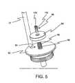
- FIG. 5shows the components of the upper catheter-holding element.
- a threaded tube 92Extending from substantially the center of the rotating base plate 90, is a threaded tube 92 .
- This tubeis the external end of the passageway through which the catheter tip with the stent attached is inserted in order to deploy the stent in the application compartment of the coating device.
- the tubeis cut longitudinally several times, to create threaded sections 98 , here six, that are configured so as to flex outward from the center.
- the tightening-disk 94has a correspondingly threaded center hole for deployment on the tube 92 such that when the tightening-disk is brought to a position proximal to the base plate, the threaded sections near the end of the tube will flex outwardly thereby enlarging the diameter of the opening.
- the gripping element 96also has divergently flexing "fingers" 100 . In operation, the gripping element is deployed around the catheter, which is then passed through the tube and into the application compartment. Once the catheter is positioned on the catheter-holding base, the gripping element is at least partially inserted into the opening of the tube.
- the tightening-disk 94is then rotated about the tube, and thereby brought to a position proximal to the end of the tube, the outwardly flexing sections of the tube 98 are brought into an un-flexed state thereby decreasing the diameter of the opening.
- the decrease in the diameter of the tube openingpushes the "fingers" of the gripping element against the catheter, thereby holding the catheter in place.
- the object itselfmay have only one type of surface.
- the scanning devicemay be configured so as to provide adjustable scanning sensitivity. In such a case, the sensitivity of the scanning device may be adjusted such that the out-put is indicative of only one type of surface and the processing unit is unable to distinguish between different types of surfaces.
Landscapes
- Media Introduction/Drainage Providing Device (AREA)
- Application Of Or Painting With Fluid Materials (AREA)
- Materials For Medical Uses (AREA)
- Prostheses (AREA)
- Coating Apparatus (AREA)
- Eye Examination Apparatus (AREA)
Abstract
Description
- The present invention relates to the coating of medical devices intended for in vivo deployment and, in particular, it concerns a method and device, which is suitable for use in an operating theater just prior to implantation, for selectively applying a medical coating to an implantable medical device, for example a stent.
- The practice of coating implantable medical devices with a synthetic or biological active or inactive agent is known. Numerous processes have been proposed for the application of such a coating. Soaking or dipping the implantable device in a bath of liquid medication is suggested by
U.S. Patent 5,922,393 to Jayaraman , soaking in an agitated bath,U.S Patent 6,129,658 to Delfino et al. Devices introducing heat and/or ultrasonic energy in conjunction with the medicated bath are disclosed inU.S. Patents 5,891,507 to Jayaraman and6,245,104 B1 to Alt. The device ofU.S. Patent 6,214,115 B1 to Taylor et al. suggest spraying the medication by way of pressurized nozzles. - Initially such coating were applied at the time of manufacture. For various reasons such as the short shelf life of some drugs combined with the time span from manufacture to implantation and the possible decision of the medical staff involved concerning the specific drug and dosage to be used based on the patient's at the time of implantation, have lead to methods and devices for applying a coating just prior to implantation. Wrapping the implantable device with medicated conformal film is disclosed in
U.S. Patent 6,309,380 B1 to Larson et al. Dipping or soaking in a medicated bath just prior to implantation are suggested inU.S. Patents 5,871,436 to Eury ,6,106,454 to Berg et al. , and6,1171,232 B1 Papandreou et al. U.S. Patent 6,203,551 B1 to Wu provides a bathing chamber for use with specific implantable device such as the stent deployed on the balloon of a catheter (fig. 1 ). - Each of the methods and devices intended for use just prior to implantation, listed above, deposit the coating material onto any and all surfaces that are exposed to the coating. This may result in depositing coating material on surfaces on which the coating is unwanted or undesirable. Further, the coating may crack or break away when the implantable is removed from the implantation apparatus. An example of this would be a stent deployed on a catheter balloon. As the balloon is inflated and the stent is expanded into position, the coating may crack along the interface between the stent and the balloon. These cracks may lead to a breaking away of a portion of the coating from the stent itself. This, in turn, may affect the medicinal effectiveness of the coating, and negatively affect the entire medical procedure.
- It is further know to use Ink-Jet technology to apply a liquid to selected portion of a surface. In the paper "Applications of Ink-Jet Printing Technology to BioMEMS and Microfluidic Systems," presented at the SPIC Conference on Microfluidics and BioMEMS, October, 2001, the authors, Patrick Cooley, David Wallace, and Bogdan Antohe provide a fairly detailed description of Ink-Jet technology and the range of its medically related applications (http://www.microfab.com/papers/papers_pdf/spie_biomems_01_reprint.pdf). A related device is disclosed in
U.S. Patent 6,001,311 to Brennan , which uses a moveable two-dimensional array of nozzles to deposit a plurality of different liquid reagents into receiving chambers. In the presentation of Cooley and the device of Brennan, the selective application of the material is based on an objective predetermined location of deposit rather that on a subjective placement as needed to meet the requirements of a specific application procedure. With regard to the application of coatings applied to medical devices with ink-jet applicators, while it is possible to coat only a chosen portion of a device, such as only the stent mounted of a catheter, but not the catheter itself. This type of procedure using current device may, however, require providing complex data files, such as a CAD image of the device to be coated, and insuring that the device be installed in the coating apparatus in a precise manner so as to be oriented exactly the same as the CAD image. - There is therefore a need for a device, and method for its use, whereby a coating is selectively applied to an implantable medical device just prior to implantation, such that only the device or selected portions thereof are coated. It would be desirable for the device to provide for user selection of coating material and dosage to be applied, thereby providing choices as to the specific coating material and dosage to be applied based on the specific needs of the patient at the time of implantation. It would be further desirable for the device to provide a sterile environment in which the coating is applied and the device is suitable for use in an operating theater.
- The present invention is a method and device, which is suitable for use in an operating theater just prior to implantation, for selectively applying a medical coating to an implantable medical device, for example a stent.
- According to the teachings of the present invention there is provided, a coating device for selectively applying a coating to surfaces of an object, the device applying the coating based upon optical properties of the surfaces such that the coating is applied to surfaces of a first type and is not applied to surfaces of a second type, the first type of surface being optically distinguishable from the second type of surface, the coating device comprising: at least one object-holding element configured to hold the object while a coating is applied; at least one optical scanning device deployed so as to scan at least a portion of the object, the optical scanning device configured so as to produce output indicative of the types of surfaces of the object; at least one coating applicator deployed so as to deposit a fluid so as to coat at least a portion of the object; at least one fluid delivery system in fluid communication so as to supply the fluid to the coating applicator; a processing unit being responsive at least to the output so as to selectively activate the coating applicator, thereby applying the coating substantially only to surfaces of the first type; and a drive system configured so as to provide relative motion between the surface of the object and the coating applicator, and between the surface of the object and the optical scanning device.
- According to a further teaching of the present invention, the drive system is configured so as to rotate the object-holding element about an axis perpendicular to a direction of application of the coating applicator.
- According to a further teaching of the present invention, the at least one object-holding element is implemented as two object-holding elements configured so as to simultaneously support the object at two different regions along a length of the object.
- According to a further teaching of the present invention, the two object-holding elements are mechanically linked so as to rotate synchronously about a single axis, the axis being perpendicular to a direction of application of the coating applicator.
- According to a further teaching of the present invention, the at least one coating applicator includes a pressure-pulse actuated drop-ejection system with at least one nozzle.
- According to a further teaching of the present invention, a spatial relationship between the coating applicator and the object is variable.
- According to a further teaching of the present invention, the spatial relationship is varied along a first axis that is parallel to a direction of application of the coating applicator, and a second axis that is perpendicular to the direction of application of the coating applicator.
- According to a further teaching of the present invention, the coating applicator is displaceable relative to the object-holding element, the displacement being along the first axis and the second axis, thereby varying the spatial relationship.
- According to a further teaching of the present invention, both the coating applicator and the optical scanning device are deployed on a displaceable applicator base, displaceable relative to the object-holding element, the displacement being along the first axis and the second axis, thereby varying the spatial relationship.
- According to a further teaching of the present invention, the at least one coating applicator is implemented as a plurality of coating applicators and the at least one fluid delivery system is implemented as an equal number of fluid delivery systems, each fluid delivery system supplying a different fluid coating material to the coating applicator with which the each fluid delivery system is in fluid communication.
- According to a further teaching of the present invention, the object is a catheter that includes a balloon portion on which a stent is deployed, such that the stent is a surface of the first type and the balloon is a surface of the second type surface.
- According to a further teaching of the present invention, the processing unit is responsive to an indication of the relative motion so as to change operational parameters of the coating device as required.
- According to a further teaching of the present invention, the object-holding element, the coating applicator, the optical scanning device, the drive system and at least a portion of the fluid delivery system are deployed within a housing that includes an application compartment.
- According to a further teaching of the present invention, the housing includes a base housing section and a detachable housing section.
- According to a further teaching of the present invention, the application compartment is defined by portions of both the base housing section and the detachable housing section.
- According to a further teaching of the present invention, the base housing section includes the coating applicator, at least a portion of the fluid delivery system, the optical scanning device and the processing unit and at least a first portion of the drive system, and the detachable housing section includes the object-holding element and at least a second portion of the drive system.
- According to a further teaching of the present invention, the base housing section includes at least one fluid delivery system.
- According to a further teaching of the present invention, the detachable housing section is disposable.
- According to a further teaching of the present invention, the application compartment is a substantially sterile environment.
- According to a further teaching of the present invention, the coating applicator, and the fluid delivery system are included in a removable sub-housing, the removable sub-housing being deployed with in the application compartment and the removable housing being detachably connected to the processing unit.
- There is also provided according to the teachings of the present invention, a coating device for selectively applying a coating to surfaces of an object, the device applying the coating based upon optical properties of the surfaces such that the coating is applied to surfaces of a first type and is not applied to surfaces of a second type, the first type of surface being optically distinguishable from the second type of surface, the coating device comprising: a) a housing which includes an application compartment; b) at least one object-holding element deployed within the application compartment, the object-holding element configured to hold the object to which a coating is applied; c) a displaceable applicator base deployed within the application compartment, the applicator base including: i) at least one coating applicator aligned so as to deposit a fluid whereby at least a portion of the object is coated; and ii) at least one optical scanning device deployed so as to scan at least a portion of the object, the optical scanning device configured so as to produce output indicative of the different types of surfaces of the object, the displacement of the applicator base resulting in a variance of a spatial relationship between the coating applicator base and the object; d) at least one fluid delivery system in fluid communication so as to supply the fluid to the coating applicator; e) a processing unit being responsive at least to the output so as to selectively activate the coating applicator, thereby applying the coating substantially only to surfaces of the first type; and f) a drive system configured so as to provide relative motion between the surface of the object and the applicator base.
- According to a further teaching of the present invention, the housing includes a base housing section and a detachable housing section.
- According to a further teaching of the present invention, the application compartment is defined by portions of both the base housing and the detachable housing section.
- According to a further teaching of the present invention, the base housing section includes the displaceable applicator base, at least a portion of the fluid delivery system, and the processing unit, and at least a first portion of the drive system, and the detachable housing section includes the object-holding element and at least a second portion of the drive system.
- According to a further teaching of the present invention, the base housing section includes at least one fluid delivery system.
- According to a further teaching of the present invention, the detachable housing section is disposable.
- According to a further teaching of the present invention, the drive system is configured so as to rotate the object-holding element about an axis perpendicular to a direction of application of the coating applicator.
- According to a further teaching of the present invention, the at least one object-holding element is implemented as two object-holding elements configured so as to simultaneously support the object at two different regions along a length of the object.
- According to a further teaching of the present invention, the two object-holding elements are mechanically linked so as to rotate synchronously about a single axis, the axis being perpendicular to a direction of application of the coating applicator.
- According to a further teaching of the present invention, the at least one coating applicator includes a pressure-pulse actuated drop-ejection system with at least one nozzle.
- According to a further teaching of the present invention, the at least one fluid delivery system is deployed in the base housing.
- According to a further teaching of the present invention, the at least one coating applicator is implemented as a plurality of coating applicators and the at least one fluid delivery system is implemented as a like number of fluid delivery systems, each fluid delivery system supplying a different fluid coating material to the coating applicator with which the each fluid delivery system is in fluid communication.
- According to a further teaching of the present invention, the coating applicator, and the fluid delivery system are included in a removable sub-housing, the removable sub-housing being detachably connected to the displaceable applicator base.
- According to a further teaching of the present invention, the spatial relationship is varied along two axes, a first axis that is parallel to a direction of application of the coating applicator, and a second axis that is perpendicular to the direction of application of the coating applicator.
- According to a further teaching of the present invention, the object is a catheter that includes a balloon portion on which a stent is deployed, such that the stent is a surface of the first type and the balloon is a surface of the second type.
- According to a further teaching of the present invention, the processing unit is responsive to an indication of the relative motion so as to change operational parameters of the coating device as required.
- There is also provided according to the teachings of the present invention, a coating method for selectively applying a coating to surfaces of an object, the method applying the coating based upon optical properties of the surfaces such that the coating is applied to surfaces of a first type and is not applied to surfaces of a second type, the first type of surface being optically distinguishable from the second type of surface, the coating device comprising: generating relative movement between the object and at least one optical scanning device and at least one coating applicator; optically scanning at least a portion of the object by use of the at least one optical scanning device so as to produce output indicative of the different types of surfaces of the object; responding to the output by selectively activating the coating applicator, thereby applying the coating substantially only to surfaces of the first type.
- According to a further teaching of the present invention, the relative movement includes rotating the object about an axis perpendicular to a direction of application of the coating applicator.
- According to a further teaching of the present invention, there is also provided simultaneously supporting the object at two different regions along a length of the object.
- According to a further teaching of the present invention, the selective activation includes selectively activating a pressure-pulse actuated drop-ejection system with at least one nozzle.
- According to a further teaching of the present invention, the selective activation includes selectively activating a pressure-pulse actuated drop-ejection system with at least one nozzle that is included in a removable sub-housing, the removable sub-housing further including a fluid delivery system in fluid communication so as to supply coating material to the coating applicator.
- According to a further teaching of the present invention, the applying is preformed by selectively activating one of a plurality of coating applicators, wherein the at least one coating applicator implemented as the plurality of coating applicators, each of the plurality of coating applicators applying a different coating.
- According to a further teaching of the present invention, the applying is preformed by selectively activating, in sequence, the plurality of coating applicators, thereby applying a plurality of layered coats, each one of the plurality of layered coats being of a coating material that is different from adjacent layered coats.
- According to a further teaching of the present invention, responding to the output includes the output being indicative of a balloon portion of catheter and a stent deployed on the balloon, such that the stent is a surface of the first type and the balloon is a surface of the second type.
- According to a further teaching of the present invention, responding to the output includes the output being indicative only of a surface of the first type thereby applying the coating to substantially the entire surface of the object.
- According to a further teaching of the present invention, there is also provided varying a spatial relationship between the coating applicator and the object.
- According to a further teaching of the present invention, the varying is along two axes, a first axis that is parallel to a direction of application of the coating applicator, and a second axis that is perpendicular to the direction of application of the coating applicator.
- According to a further teaching of the present invention, the varying is accomplished by displacing the coating applicator.
- According to a further teaching of the present invention, the varying is accomplished by varying the spatial relationship between the object and a displaceable applicator base upon which the at least one coating applicator and the at least one optical scanning device are deployed.
- According to a further teaching of the present invention, controlling the varying is accomplished by the processing unit.
- According to a further teaching of the present invention, there is also provided responding to an indication of the relative motion so as to change operational parameters of the coating device as required.
- According to a further teaching of the present invention, generating relative movement, the optically scanning at least a portion of the object, and the selectively activating the coating are preformed within a housing.
- The invention is herein described, by way of example only, with reference to the accompanying drawings, wherein:
FIG. 1 is a cut-away side elevation of a stent coating device constructed and operative according to the teachings of the present invention.FIG. 2 is a cut-away perspective view of the stent coating device ofFIG. 1 .FIG. 3 is a perspective detail of an alternative displaceable applicator head constructed and operative according to the teachings of the present invention, shown here configure with disposable coating applicators.FIG. 4 is a cut-away perspective view of the stent coating device ofFIG. 1 , showing the detachable section of the housing separated from the base section of the housing.FIG. 5 is a perspective detail of an upper stent holding element, constructed and operative according to the teachings of the present invention.FIG. 6 is a side elevation of the stent coating device ofFIG. 1 showing the full length of a catheter being supported by the support antenna.- The present invention is a method and device, which is suitable for use in an operating theater just prior to implantation, for selectively applying a medical coating to an implantable medical device, for example a stent.
- The principles and operation of a coating device according to the present invention may be better understood with reference to the drawings and the accompanying description.
- By way of introduction, the embodiment discussed herein is a device for applying a medical coating to a stent deployed on a catheter, the coating being applied just prior to implantation and if desired in the operating theater. The use of optical scanning devices enables a processing unit to distinguish between the surface area of the stent and the surface area of the catheter. The processing unit selectively activates the coating applicator so as to apply the coating to substantially only the stent and not the balloon or other portion of the catheter. The coating applicator discussed herein is, by non-limiting example, a pressure-pulse actuated drop-ejection system with at least one nozzle. A readily available pressure-pulse actuated drop-ejection system, which is well suited for the present invention, is a drop-on-demand ink-jet system. It should be noted, however, that any coating application system that may be selectively activated is within the intentions of the present invention. While the discussion herein is specific to this embodiment, which is intended for use in an operating theater, among other places, this embodiment it is intended as a non-limiting example of the principals of the present invention. It will be readily apparent to one skilled in the art, the range of applications suited to the principals of the present invention. Even the device described herein, as a non-limiting example, with minor adaptations to the object-holding element and choice of fluid coating materials, is well suited for a wide range of objects to which a coating is applied.
- Referring now to the drawings, as mentioned above,
Figures1 illustrates a device for applying a coating to astent 2 that is deployed on acatheter 4. The coating being applied may be a synthetic or biological, active or inactive agent. The perspective view ofFigure 2 is of the same side of the device asFigure1 , and therefore when the description of elements of the device will be better understood,Figure 2 will be referenced. Thecatheter 4 is placed in anapplication compartment 40 and held in position by a rotatable catheter-holdingbase 6 and a rotatable upper catheter-holdingelement 8, which are configured for substantially continued rotation, that is they may complete a plurality of full 360 degree rotations, as required, during the coating process. The actual rotation may be substantially fully continuous (non-stop) or intermittent. The upper catheter-holding element will be discussed in detail below with regard toFigure 4 . The enclosed application compartment provides a sterile environment in which the coating process is performed. The rotation of the catheter-holding base and the upper catheter-holding element is actuated and synchronized by a motor10 and gear system that includesgear clusters Figure 2 ). Alternatively, the gears may be replaced by drive belts or drive chains. The remaining length of thecatheter 20 is supported by asupport antenna 22, as illustrated, by non-limiting example, inFigure 6 . As noted above, the object-holding elements may be modified so as to hold any object suitable for coating according to the teachings of the present invention. - The coating is applied by a drop-on-demand ink-jet system in association with an optical scanning device and processing unit. As the object is rotated by the object-holding element, the optical scanning device scans the surface of the object. The out-put from the scanning device is used by the processing unit to determine if the surface area currently aligned with the coating applicator is of the type of surface to be coated. When it is determined that the desired type of surface is aligned with the coating applicator, the processing unit activates the coating applicator and the coating is dispensed. The embodiment shown here includes three ink-
jet coating applicators optical scanning devices displaceable applicator head 34. The position of the applicator head within the application compartment, and thereby the spatial relationship between the coating applicator and the stent, or other object being coated, is regulated by theapplication control module 36, which is, in turn, controlled by the processing unit. The change of position of the applicator head is effected vertically by turning thevertical positioning screw 60 in conjunction withguide shaft 62, and the horizontally by turning thehorizontal positioning screw 64 in conjunction withguide shaft 66. The vertical repositioning in conjunction with the rotation of the object enables the coating applicator to traverse substantially the entire surface of the object requiring coating. - Fluid coating material is stored in three
fluid reservoirs Figure 2 ), and supplied to the respective coating applicators by thefluid supply hoses Figure 2 ). In general use, each of the fluid reservoirs contains a different coating material, thus, each coating applicator will deposit a different coating material on the stent or other objected being coated, as required. Further, a plurality of coats may be applied, each coat being of a different coating material and, if required, of a different thickness. Thus, at the time of coating, a single appropriate coating material may be chosen from the materials provides, or a combination of coatings may be chosen. It should be noted that while the fluid reservoirs are shown here in a compartment inside the device housing, this need not always be the case, and the reservoirs may be external to the housing. - It should be noted that, alternatively, the ink-jet system may be deployed in a disposable housing that also includes a fluid reservoir filled with coating material. The fluid reservoir may be an enclosed volume that is integral to the disposable housing or it may be a coating filled cartridge that is inserted into a receiving cavity in the disposable housing. In this case, as illustrated in
Figure 3 , thedisplaceable applicator head 34 is configured so as to accept one or more of thedisposable housings jet coating applicators displaceable applicator head 34. Figure 4 illustrates how thebase housing section 70 and thedetachable housing section 72 are interconnected. The two sections are held together by insertingpins 74, extending from the detachable housing section, into the correspondingholes 76, located in the base housing section, and engaging thelatch mechanism 78 with thecatch element 80. Detachment of the two sections is accomplished by pressing the release "button"84, which raises theend 82 of the latch thereby releasing the catch element. The two sections are then pulled apart. As seen here more clearly, the application compartment is defined by a top, floor and three walls located in the detachable housing section and one wall on the base housing section. The detachable housing section is configured so as to be disposable, or if desired, easily cleaned and re-sterilized.- The detail of
Figure 5 shows the components of the upper catheter-holding element. Extending from substantially the center of the rotatingbase plate 90, is a threadedtube 92. This tube is the external end of the passageway through which the catheter tip with the stent attached is inserted in order to deploy the stent in the application compartment of the coating device. The tube is cut longitudinally several times, to create threadedsections 98, here six, that are configured so as to flex outward from the center. The tightening-disk 94, has a correspondingly threaded center hole for deployment on thetube 92 such that when the tightening-disk is brought to a position proximal to the base plate, the threaded sections near the end of the tube will flex outwardly thereby enlarging the diameter of the opening. The grippingelement 96 also has divergently flexing "fingers"100. In operation, the gripping element is deployed around the catheter, which is then passed through the tube and into the application compartment. Once the catheter is positioned on the catheter-holding base, the gripping element is at least partially inserted into the opening of the tube. The tightening-disk 94 is then rotated about the tube, and thereby brought to a position proximal to the end of the tube, the outwardly flexing sections of thetube 98 are brought into an un-flexed state thereby decreasing the diameter of the opening. The decrease in the diameter of the tube opening pushes the "fingers" of the gripping element against the catheter, thereby holding the catheter in place. - A non-limiting example of the stent coating process as accomplished by the above describe device would be as follows:
- 1. The fluid reservoirs are filled with the required fluid coating materials.
- 2. The parameters of the coating are inputted into the processing unit. The parameters may include, by non-limiting example, the coating material to be applied, the thickness of the coating, number of multiple layers of different coating material, the order in which the layered materials are to be applied, and the thickness of each layer. The parameters may be determined by the physician at the time the coating is applied or the parameters may be pre-set, such as those determined by medical regulations. In the case of pre-set parameters, the physician would simply input a "start" command.
- 3. The catheter is positioned in the application compartment and the upper catheter-holding element is tightened.
- 4. As the catheter rotates, the optical scanning device scans the surface of the catheter, to distinguish between the surface of the balloon and the surface of the stent.
- 5. When a portion of the surface of the stent is detected and determined to be in alignment with the appropriate coating applicator, the processing unit selectively activates the applicator, thereby ejecting the necessary amount of coating material, which is deposited substantially only on the surface of the stent.
- 6. Throughout the coating process, the position of the applicator head is adjusted as required. This adjustment may bring the coating applicator closer to, or farther away from, the surface of the stent, and it may adjust the vertical deployment of the coating applicator, thereby allowing different areas of the surface of the stent to be coated. Further, if a different fluid coating material is needed for a different layer of the coating, the coating applicator for that particular coating material may be brought into appropriate alignment for deposition of the new coating material on the stent.
- 7. When the coating process is completed, the catheter with the now coated stent is removed from the device, and the stent is ready for implantation.
- 8. The detachable housing section is removed and may be cleaned and sterilized for re-use, or simply discarded.
- It should be noted that in some cases it may be desirable to coat substantially the entire surface of the object being coated. This may be accomplish in at least two ways. The object itself may have only one type of surface. Alternatively, the scanning device may be configured so as to provide adjustable scanning sensitivity. In such a case, the sensitivity of the scanning device may be adjusted such that the out-put is indicative of only one type of surface and the processing unit is unable to distinguish between different types of surfaces.
- It will be appreciated that the above descriptions are intended only to serve as examples, and that many other embodiments are possible within the spirit and the scope of the present invention.
Claims (10)
- An apparatus for selectively applying a coating to surfaces of an object, wherein the object is a catheter (4), that includes a balloon portion on which a stent (2) is deployed, the surfaces of the stent (2) being optically distinguishable from the surfaces of the balloon portion, the apparatus comprising:at least one optical scanning device (32a, 32b) deployed so as to scan a portion of the object;at least one coating applicator (30a, 30b, 30c) deployed so as to deposit a fluid so as to coat at least a portion of said stent (2); anda drive system (10, 12, 14, 16, 18; 60, 62, 64, 66) deployed so as to provide relative movement between the surface of the object and said at least one optical scanning device (32a, 32b), and between the surface of the object and said at least one coating applicator (30a, 30b, 30c);characterized in thatsaid optical scanning device (32a, 32b) is configured so as to produce output indicative of optical properties of the surface of the stent (2) and the surface of the balloon portion of the catheter (4) andin that said apparatus further comprisesa processing unit (36) being responsive at least to said output so as to selectively activate said coating applicator (30a, 30b, 30c) to apply coating to the surface of the stent and not to the surface of the balloon portion depending on said output, andan application compartment (40) capable of providing a sterile environment in which the coating is selectively applied to the surface of the stent.
- The apparatus of claim 1, wherein said at least one scanning device (32a, 32b) is deployable within the application compartment (40).
- The apparatus of claim 1 or claim 2, wherein said at least one coating applicator (30a, 30b, 30c) is deployable within the application compartment (40).
- The apparatus of any preceding claim, wherein said drive system (10, 12, 14, 16, 18; 60, 62, 64, 66) is exterior to the application compartment (40).
- The apparatus of any preceding claim, wherein said drive system (10, 12, 14, 16, 18; 60, 62, 64, 66) is configured so as to rotate said object about an axis perpendicular to a direction of application of said coating applicator (30a, 30b, 30c).
- The apparatus of any preceding claim, further comprising:two object-holding elements (22, 96) configured so as to simultaneously support the object at two different regions along its length.
- The apparatus of any of claims 1 to 5, further comprising:at least one object-holding element (6) in the compartment, the at least one object-holding element being configured to rotatably support the object.
- The apparatus of any preceding claim, wherein said at least one coating applicator (30a, 30b, 30c) comprises a pressure-pulse actuated drop-ejection system (30a, 30b, 30c) comprising at least one nozzle.
- The apparatus of any preceding claim, wherein said at least one coating applicator is implemented as a plurality of coating applicators (30a, 30b, 30c), and wherein each of said plurality of coating applicators (30a, 30b, 30c) applies a different coating.
- The apparatus of any preceding claim, wherein the application compartment makes the apparatus suitable for use in an operating theater just prior to implantation of the stent.
Applications Claiming Priority (2)
| Application Number | Priority Date | Filing Date | Title |
|---|---|---|---|
| US10/136,295US6645547B1 (en) | 2002-05-02 | 2002-05-02 | Stent coating device |
| EP03725548AEP1499450B1 (en) | 2002-05-02 | 2003-05-01 | Stent coating device |
Related Parent Applications (2)
| Application Number | Title | Priority Date | Filing Date |
|---|---|---|---|
| EP03725548ADivisionEP1499450B1 (en) | 2002-05-02 | 2003-05-01 | Stent coating device |
| EP03725548.6Division | 2003-05-01 |
Publications (2)
| Publication Number | Publication Date |
|---|---|
| EP2020265A1true EP2020265A1 (en) | 2009-02-04 |
| EP2020265B1 EP2020265B1 (en) | 2012-03-07 |
Family
ID=29268919
Family Applications (2)
| Application Number | Title | Priority Date | Filing Date |
|---|---|---|---|
| EP03725548AExpired - LifetimeEP1499450B1 (en) | 2002-05-02 | 2003-05-01 | Stent coating device |
| EP08019305AExpired - LifetimeEP2020265B1 (en) | 2002-05-02 | 2003-05-01 | Stent coating device |
Family Applications Before (1)
| Application Number | Title | Priority Date | Filing Date |
|---|---|---|---|
| EP03725548AExpired - LifetimeEP1499450B1 (en) | 2002-05-02 | 2003-05-01 | Stent coating device |
Country Status (9)
| Country | Link |
|---|---|
| US (8) | US6645547B1 (en) |
| EP (2) | EP1499450B1 (en) |
| AT (2) | ATE548126T1 (en) |
| AU (1) | AU2003228079A1 (en) |
| CA (1) | CA2485069C (en) |
| DE (1) | DE60324543D1 (en) |
| ES (1) | ES2322344T3 (en) |
| IL (2) | IL164983A0 (en) |
| WO (1) | WO2003092909A1 (en) |
Cited By (1)
| Publication number | Priority date | Publication date | Assignee | Title |
|---|---|---|---|---|
| CN107029942A (en)* | 2016-11-07 | 2017-08-11 | 深圳市万至达电机制造有限公司 | A kind of hollow cup motor rotor point glue equipment |
Families Citing this family (139)
| Publication number | Priority date | Publication date | Assignee | Title |
|---|---|---|---|---|
| US6776792B1 (en) | 1997-04-24 | 2004-08-17 | Advanced Cardiovascular Systems Inc. | Coated endovascular stent |
| US20040254635A1 (en) | 1998-03-30 | 2004-12-16 | Shanley John F. | Expandable medical device for delivery of beneficial agent |
| US6241762B1 (en) | 1998-03-30 | 2001-06-05 | Conor Medsystems, Inc. | Expandable medical device with ductile hinges |
| US7208011B2 (en) | 2001-08-20 | 2007-04-24 | Conor Medsystems, Inc. | Implantable medical device with drug filled holes |
| US7208010B2 (en) | 2000-10-16 | 2007-04-24 | Conor Medsystems, Inc. | Expandable medical device for delivery of beneficial agent |
| EP1498084B1 (en) | 2000-10-16 | 2014-06-18 | Innovational Holdings, LLC | Expandable medical device for delivery of beneficial agent |
| US6783793B1 (en) | 2000-10-26 | 2004-08-31 | Advanced Cardiovascular Systems, Inc. | Selective coating of medical devices |
| US20040073294A1 (en) | 2002-09-20 | 2004-04-15 | Conor Medsystems, Inc. | Method and apparatus for loading a beneficial agent into an expandable medical device |
| EP1258230A3 (en) | 2001-03-29 | 2003-12-10 | CardioSafe Ltd | Balloon catheter device |
| US6565659B1 (en) | 2001-06-28 | 2003-05-20 | Advanced Cardiovascular Systems, Inc. | Stent mounting assembly and a method of using the same to coat a stent |
| US6682771B2 (en)* | 2001-07-02 | 2004-01-27 | Scimed Life Systems, Inc. | Coating dispensing system and method using a solenoid head for coating medical devices |
| US7927650B2 (en)* | 2001-08-20 | 2011-04-19 | Innovational Holdings, Llc | System and method for loading a beneficial agent into a medical device |
| US7056338B2 (en) | 2003-03-28 | 2006-06-06 | Conor Medsystems, Inc. | Therapeutic agent delivery device with controlled therapeutic agent release rates |
| GB0121980D0 (en) | 2001-09-11 | 2001-10-31 | Cathnet Science Holding As | Expandable stent |
| JP2005507754A (en) | 2001-11-08 | 2005-03-24 | アトリウム メディカル コーポレイション | Intraluminal device having a coating containing a therapeutic agent |
| US20030135266A1 (en) | 2001-12-03 | 2003-07-17 | Xtent, Inc. | Apparatus and methods for delivery of multiple distributed stents |
| US7147656B2 (en) | 2001-12-03 | 2006-12-12 | Xtent, Inc. | Apparatus and methods for delivery of braided prostheses |
| US7294146B2 (en) | 2001-12-03 | 2007-11-13 | Xtent, Inc. | Apparatus and methods for delivery of variable length stents |
| US20040186551A1 (en) | 2003-01-17 | 2004-09-23 | Xtent, Inc. | Multiple independent nested stent structures and methods for their preparation and deployment |
| US7270668B2 (en) | 2001-12-03 | 2007-09-18 | Xtent, Inc. | Apparatus and methods for delivering coiled prostheses |
| US7309350B2 (en) | 2001-12-03 | 2007-12-18 | Xtent, Inc. | Apparatus and methods for deployment of vascular prostheses |
| US7351255B2 (en) | 2001-12-03 | 2008-04-01 | Xtent, Inc. | Stent delivery apparatus and method |
| US7137993B2 (en) | 2001-12-03 | 2006-11-21 | Xtent, Inc. | Apparatus and methods for delivery of multiple distributed stents |
| US7892273B2 (en) | 2001-12-03 | 2011-02-22 | Xtent, Inc. | Custom length stent apparatus |
| US8080048B2 (en) | 2001-12-03 | 2011-12-20 | Xtent, Inc. | Stent delivery for bifurcated vessels |
| US7182779B2 (en) | 2001-12-03 | 2007-02-27 | Xtent, Inc. | Apparatus and methods for positioning prostheses for deployment from a catheter |
| US6645547B1 (en)* | 2002-05-02 | 2003-11-11 | Labcoat Ltd. | Stent coating device |
| US7709048B2 (en)* | 2002-05-02 | 2010-05-04 | Labcoat, Ltd. | Method and apparatus for coating a medical device |
| US7048962B2 (en)* | 2002-05-02 | 2006-05-23 | Labcoat, Ltd. | Stent coating device |
| US7758636B2 (en) | 2002-09-20 | 2010-07-20 | Innovational Holdings Llc | Expandable medical device with openings for delivery of multiple beneficial agents |
| US7192484B2 (en) | 2002-09-27 | 2007-03-20 | Surmodics, Inc. | Advanced coating apparatus and method |
| US8524148B2 (en)* | 2002-11-07 | 2013-09-03 | Abbott Laboratories | Method of integrating therapeutic agent into a bioerodible medical device |
| US8221495B2 (en) | 2002-11-07 | 2012-07-17 | Abbott Laboratories | Integration of therapeutic agent into a bioerodible medical device |
| US7208190B2 (en)* | 2002-11-07 | 2007-04-24 | Abbott Laboratories | Method of loading beneficial agent to a prosthesis by fluid-jet application |
| US7211150B1 (en) | 2002-12-09 | 2007-05-01 | Advanced Cardiovascular Systems, Inc. | Apparatus and method for coating and drying multiple stents |
| US8318235B2 (en)* | 2003-01-22 | 2012-11-27 | Cordis Corporation | Method for applying drug coating to a medical device in surgeon room |
| US8281737B2 (en) | 2003-03-10 | 2012-10-09 | Boston Scientific Scimed, Inc. | Coated medical device and method for manufacturing the same |
| AU2004226327A1 (en) | 2003-03-28 | 2004-10-14 | Innovational Holdings, Llc | Implantable medical device with beneficial agent concentration gradient |
| DE10318803B4 (en)* | 2003-04-17 | 2005-07-28 | Translumina Gmbh | Device for applying active substances to surfaces of medical implants, in particular stents |
| US7482034B2 (en)* | 2003-04-24 | 2009-01-27 | Boston Scientific Scimed, Inc. | Expandable mask stent coating method |
| US7241308B2 (en) | 2003-06-09 | 2007-07-10 | Xtent, Inc. | Stent deployment systems and methods |
| WO2005011561A2 (en)* | 2003-08-04 | 2005-02-10 | Labcoat, Ltd. | Stent coating apparatus and method |
| US20050048194A1 (en)* | 2003-09-02 | 2005-03-03 | Labcoat Ltd. | Prosthesis coating decision support system |
| US20050058768A1 (en)* | 2003-09-16 | 2005-03-17 | Eyal Teichman | Method for coating prosthetic stents |
| US7785653B2 (en)* | 2003-09-22 | 2010-08-31 | Innovational Holdings Llc | Method and apparatus for loading a beneficial agent into an expandable medical device |
| US7198675B2 (en) | 2003-09-30 | 2007-04-03 | Advanced Cardiovascular Systems | Stent mandrel fixture and method for selectively coating surfaces of a stent |
| US7553324B2 (en) | 2003-10-14 | 2009-06-30 | Xtent, Inc. | Fixed stent delivery devices and methods |
| US8636721B2 (en) | 2003-11-20 | 2014-01-28 | Henry M. Jackson Foundation For The Advancement Of Military Medicine, Inc. | Portable hand pump for evacuation of fluids |
| US7403966B2 (en)* | 2003-12-08 | 2008-07-22 | Freescale Semiconductor, Inc. | Hardware for performing an arithmetic function |
| US7326236B2 (en) | 2003-12-23 | 2008-02-05 | Xtent, Inc. | Devices and methods for controlling and indicating the length of an interventional element |
| US7563324B1 (en) | 2003-12-29 | 2009-07-21 | Advanced Cardiovascular Systems Inc. | System and method for coating an implantable medical device |
| US7323006B2 (en) | 2004-03-30 | 2008-01-29 | Xtent, Inc. | Rapid exchange interventional devices and methods |
| US7553377B1 (en) | 2004-04-27 | 2009-06-30 | Advanced Cardiovascular Systems, Inc. | Apparatus and method for electrostatic coating of an abluminal stent surface |
| US20060240065A1 (en)* | 2005-04-26 | 2006-10-26 | Yung-Ming Chen | Compositions for medical devices containing agent combinations in controlled volumes |
| US20050251152A1 (en)* | 2004-05-05 | 2005-11-10 | Atrium Medical Corp. | Illuminated medicated ink marker |
| US20050288766A1 (en) | 2004-06-28 | 2005-12-29 | Xtent, Inc. | Devices and methods for controlling expandable prostheses during deployment |
| US8317859B2 (en) | 2004-06-28 | 2012-11-27 | J.W. Medical Systems Ltd. | Devices and methods for controlling expandable prostheses during deployment |
| USD516723S1 (en) | 2004-07-06 | 2006-03-07 | Conor Medsystems, Inc. | Stent wall structure |
| US20060029720A1 (en)* | 2004-08-03 | 2006-02-09 | Anastasia Panos | Methods and apparatus for injection coating a medical device |
| US9801913B2 (en) | 2004-09-28 | 2017-10-31 | Atrium Medical Corporation | Barrier layer |
| WO2006036982A2 (en) | 2004-09-28 | 2006-04-06 | Atrium Medical Corporation | Drug delivery coating for use with a stent |
| US8124127B2 (en) | 2005-10-15 | 2012-02-28 | Atrium Medical Corporation | Hydrophobic cross-linked gels for bioabsorbable drug carrier coatings |
| US8367099B2 (en) | 2004-09-28 | 2013-02-05 | Atrium Medical Corporation | Perforated fatty acid films |
| US9801982B2 (en) | 2004-09-28 | 2017-10-31 | Atrium Medical Corporation | Implantable barrier device |
| US9000040B2 (en) | 2004-09-28 | 2015-04-07 | Atrium Medical Corporation | Cross-linked fatty acid-based biomaterials |
| US9012506B2 (en) | 2004-09-28 | 2015-04-21 | Atrium Medical Corporation | Cross-linked fatty acid-based biomaterials |
| US8312836B2 (en) | 2004-09-28 | 2012-11-20 | Atrium Medical Corporation | Method and apparatus for application of a fresh coating on a medical device |
| US8337475B2 (en) | 2004-10-12 | 2012-12-25 | C. R. Bard, Inc. | Corporeal drainage system |
| US7632307B2 (en) | 2004-12-16 | 2009-12-15 | Advanced Cardiovascular Systems, Inc. | Abluminal, multilayer coating constructs for drug-delivery stents |
| CN100374092C (en)* | 2005-01-14 | 2008-03-12 | 大连理工大学 | Preparation method of drug coating for vascular stent and electrostatic spraying device thereof |
| US7749553B2 (en)* | 2005-01-31 | 2010-07-06 | Boston Scientific Scimed, Inc. | Method and system for coating a medical device using optical drop volume verification |
| EP1866007B1 (en)* | 2005-03-31 | 2011-11-16 | Innovational Holdings, LLC | System and method for loading a beneficial agent into a medical device |
| US7402168B2 (en) | 2005-04-11 | 2008-07-22 | Xtent, Inc. | Custom-length stent delivery system with independently operable expansion elements |
| US7938851B2 (en) | 2005-06-08 | 2011-05-10 | Xtent, Inc. | Devices and methods for operating and controlling interventional apparatus |
| US8157851B2 (en) | 2005-06-08 | 2012-04-17 | Xtent, Inc. | Apparatus and methods for deployment of multiple custom-length prostheses |
| US20070032865A1 (en)* | 2005-08-05 | 2007-02-08 | Otis David R | Prosthesis having a coating and systems and methods of making the same |
| US8177772B2 (en) | 2005-09-26 | 2012-05-15 | C. R. Bard, Inc. | Catheter connection systems |
| US9278161B2 (en) | 2005-09-28 | 2016-03-08 | Atrium Medical Corporation | Tissue-separating fatty acid adhesion barrier |
| US9427423B2 (en) | 2009-03-10 | 2016-08-30 | Atrium Medical Corporation | Fatty-acid based particles |
| US8051797B1 (en) | 2005-11-07 | 2011-11-08 | Boston Scientific Scimed, Inc. | Device to stabilize and align a pre-mounted stent |
| US7833261B2 (en)* | 2005-12-12 | 2010-11-16 | Advanced Cardiovascular Systems, Inc. | Severable support for a stent |
| US7976891B1 (en) | 2005-12-16 | 2011-07-12 | Advanced Cardiovascular Systems, Inc. | Abluminal stent coating apparatus and method of using focused acoustic energy |
| US7867547B2 (en) | 2005-12-19 | 2011-01-11 | Advanced Cardiovascular Systems, Inc. | Selectively coating luminal surfaces of stents |
| WO2007109621A2 (en) | 2006-03-20 | 2007-09-27 | Xtent, Inc. | Apparatus and methods for deployment of linked prosthetic segments |
| US8003156B2 (en) | 2006-05-04 | 2011-08-23 | Advanced Cardiovascular Systems, Inc. | Rotatable support elements for stents |
| US7775178B2 (en)* | 2006-05-26 | 2010-08-17 | Advanced Cardiovascular Systems, Inc. | Stent coating apparatus and method |
| US8097291B2 (en)* | 2006-06-05 | 2012-01-17 | Boston Scientific Scimed, Inc. | Methods for coating workpieces |
| US20070281071A1 (en)* | 2006-06-06 | 2007-12-06 | Boston Scientific Scimed, Inc. | Acoustically coating workpieces |
| US8603530B2 (en) | 2006-06-14 | 2013-12-10 | Abbott Cardiovascular Systems Inc. | Nanoshell therapy |
| US8048448B2 (en) | 2006-06-15 | 2011-11-01 | Abbott Cardiovascular Systems Inc. | Nanoshells for drug delivery |
| US8017237B2 (en) | 2006-06-23 | 2011-09-13 | Abbott Cardiovascular Systems, Inc. | Nanoshells on polymers |
| US8679573B2 (en) | 2006-06-28 | 2014-03-25 | Advanced Cardiovascular Systems, Inc. | Stent coating method and apparatus |
| WO2008033199A1 (en)* | 2006-09-12 | 2008-03-20 | Boston Scientific Limited | Liquid masking for selective coating of a stent |
| DE102006050221B3 (en)* | 2006-10-12 | 2007-11-22 | Translumina Gmbh | Device for applying active substances on surfaces of medical implants, has retaining bracket at cartridge, where two cylindrical housing parts are provided, which are pluggable into each other and are sterilely sealed against each other |
| US20080097588A1 (en)* | 2006-10-18 | 2008-04-24 | Conor Medsystems, Inc. | Systems and Methods for Producing a Medical Device |
| US8733274B2 (en)* | 2006-10-20 | 2014-05-27 | Hewlett-Packard Development Company, L.P. | Tube mounted inkjet printhead die |
| US7867548B2 (en)* | 2006-10-27 | 2011-01-11 | Hewlett-Packard Development Company, L.P. | Thermal ejection of solution having solute onto device medium |
| EP2083875B1 (en) | 2006-11-06 | 2013-03-27 | Atrium Medical Corporation | Coated surgical mesh |
| US9492596B2 (en) | 2006-11-06 | 2016-11-15 | Atrium Medical Corporation | Barrier layer with underlying medical device and one or more reinforcing support structures |
| KR101198980B1 (en) | 2007-01-21 | 2012-11-07 | 헤모텍 아게 | Medical product for treating stenosis of body passages and for preventing threatening restenosis |
| US20080199510A1 (en) | 2007-02-20 | 2008-08-21 | Xtent, Inc. | Thermo-mechanically controlled implants and methods of use |
| US8486132B2 (en) | 2007-03-22 | 2013-07-16 | J.W. Medical Systems Ltd. | Devices and methods for controlling expandable prostheses during deployment |
| US8048441B2 (en) | 2007-06-25 | 2011-11-01 | Abbott Cardiovascular Systems, Inc. | Nanobead releasing medical devices |
| AU2008326154B2 (en) | 2007-10-30 | 2013-12-12 | Uti Limited Partnership | Method and system for sustained-release of sclerosing agent |
| WO2009065087A1 (en)* | 2007-11-14 | 2009-05-22 | Biosensors International Group, Ltd. | Automated coating apparatus and method |
| US9101503B2 (en) | 2008-03-06 | 2015-08-11 | J.W. Medical Systems Ltd. | Apparatus having variable strut length and methods of use |
| US9126025B2 (en)* | 2008-05-01 | 2015-09-08 | Bayer Intellectual Property Gmbh | Method of coating a folded catheter balloon |
| US12324756B2 (en) | 2008-09-25 | 2025-06-10 | Advanced Bifurcation Systems Inc. | System and methods for treating a bifurcation |
| US8821562B2 (en) | 2008-09-25 | 2014-09-02 | Advanced Bifurcation Systems, Inc. | Partially crimped stent |
| JP5635515B2 (en) | 2008-09-25 | 2014-12-03 | アドバンスド バイファケーション システムズ, インコーポレイテッド | Partially crimped stent |
| US8049061B2 (en) | 2008-09-25 | 2011-11-01 | Abbott Cardiovascular Systems, Inc. | Expandable member formed of a fibrous matrix having hydrogel polymer for intraluminal drug delivery |
| US8828071B2 (en) | 2008-09-25 | 2014-09-09 | Advanced Bifurcation Systems, Inc. | Methods and systems for ostial stenting of a bifurcation |
| US8076529B2 (en) | 2008-09-26 | 2011-12-13 | Abbott Cardiovascular Systems, Inc. | Expandable member formed of a fibrous matrix for intraluminal drug delivery |
| US11298252B2 (en) | 2008-09-25 | 2022-04-12 | Advanced Bifurcation Systems Inc. | Stent alignment during treatment of a bifurcation |
| US8226603B2 (en) | 2008-09-25 | 2012-07-24 | Abbott Cardiovascular Systems Inc. | Expandable member having a covering formed of a fibrous matrix for intraluminal drug delivery |
| US12076258B2 (en) | 2008-09-25 | 2024-09-03 | Advanced Bifurcation Systems Inc. | Selective stent crimping |
| US20100285085A1 (en)* | 2009-05-07 | 2010-11-11 | Abbott Cardiovascular Systems Inc. | Balloon coating with drug transfer control via coating thickness |
| US20110038910A1 (en) | 2009-08-11 | 2011-02-17 | Atrium Medical Corporation | Anti-infective antimicrobial-containing biomaterials |
| EP2525920B1 (en)* | 2010-01-18 | 2017-09-27 | Concept Medical Research Private Limited | Method and system for coating insertable medical devices |
| WO2011119536A1 (en) | 2010-03-22 | 2011-09-29 | Abbott Cardiovascular Systems Inc. | Stent delivery system having a fibrous matrix covering with improved stent retention |
| CN103037815B (en) | 2010-03-24 | 2015-05-13 | 高级分支系统股份有限公司 | Method and system for treating furcations by temporarily opening side branches |
| EP2549951B1 (en) | 2010-03-24 | 2017-05-10 | Advanced Bifurcation Systems, Inc. | Stent alignment during treatment of a bifurcation |
| AU2011232362B2 (en) | 2010-03-24 | 2015-12-10 | Advanced Bifurcation Systems Inc. | System and methods for treating a bifurcation |
| US8389041B2 (en) | 2010-06-17 | 2013-03-05 | Abbott Cardiovascular Systems, Inc. | Systems and methods for rotating and coating an implantable device |
| WO2012009707A2 (en) | 2010-07-16 | 2012-01-19 | Atrium Medical Corporation | Composition and methods for altering the rate of hydrolysis of cured oil-based materials |
| US20120035596A1 (en)* | 2010-08-04 | 2012-02-09 | Tegg Troy T | Disposable Drive Interface for Longitudinal Movement of an Elongate Medical Device |
| WO2012109382A2 (en) | 2011-02-08 | 2012-08-16 | Advanced Bifurcation Systems, Inc. | Multi-stent and multi-balloon apparatus for treating bifurcations and methods of use |
| EP4424283A3 (en) | 2011-02-08 | 2024-12-25 | Advanced Bifurcation Systems Inc. | System and methods for treating a bifurcation with a fully crimped stent |
| US9321066B2 (en)* | 2012-02-16 | 2016-04-26 | Sahajanand Technologies Private Limited | Drug coating apparatus |
| US9867880B2 (en) | 2012-06-13 | 2018-01-16 | Atrium Medical Corporation | Cured oil-hydrogel biomaterial compositions for controlled drug delivery |
| CN104607339B (en)* | 2015-01-22 | 2017-01-04 | 上海理工大学 | Medicine spraying Z axis system |
| WO2018017365A1 (en) | 2016-07-18 | 2018-01-25 | Merit Medical Systems, Inc. | Inflatable radial artery compression device |
| CN109550617A (en)* | 2018-12-11 | 2019-04-02 | 安徽江淮汽车集团股份有限公司 | Gear Experimentation tooling |
| CN109759256B (en)* | 2019-01-14 | 2020-03-24 | 沈阳马卡智工科技有限公司 | Automatic paste painting machine |
| CN110302921B (en)* | 2019-07-05 | 2021-03-19 | 江苏中泽电气自动化有限公司 | Metal pipe fitting processing digit control machine tool |
| CN110449294B (en)* | 2019-08-27 | 2020-12-22 | 临沂市皓正铁塔制造有限公司 | Portable quick spraying equipment |
| CN110976128B (en)* | 2019-12-12 | 2020-10-27 | 苏州德斯米尔智能科技有限公司 | Outer surface treatment device for production and manufacturing of water purifier pressure barrel |
| US12426864B2 (en) | 2021-06-18 | 2025-09-30 | Merit Medical Systems, Inc. | Hemostasis devices and methods of use |
| CN114470486A (en)* | 2021-12-08 | 2022-05-13 | 珠海博纳百润生物科技有限公司 | Guide wire clamp holder |
Citations (13)
| Publication number | Priority date | Publication date | Assignee | Title |
|---|---|---|---|---|
| US4842887A (en)* | 1986-02-01 | 1989-06-27 | Schmalbach-Lubeca Ag | Method of and system for coating exposed can edges |
| US5871436A (en) | 1996-07-19 | 1999-02-16 | Advanced Cardiovascular Systems, Inc. | Radiation therapy method and device |
| US5891507A (en) | 1997-07-28 | 1999-04-06 | Iowa-India Investments Company Limited | Process for coating a surface of a metallic stent |
| US5922393A (en) | 1996-08-06 | 1999-07-13 | Jayaraman; Swaminathan | Microporous covered stents and method of coating |
| US6001311A (en) | 1997-02-05 | 1999-12-14 | Protogene Laboratories, Inc. | Apparatus for diverse chemical synthesis using two-dimensional array |
| US6106454A (en) | 1997-06-17 | 2000-08-22 | Medtronic, Inc. | Medical device for delivering localized radiation |
| US6129658A (en) | 1997-12-10 | 2000-10-10 | Varian Associates, Inc. | Method and apparatus creating a radioactive layer on a receiving substrate for in vivo implantation |
| US6171232B1 (en) | 1997-06-26 | 2001-01-09 | Cordis Corporation | Method for targeting in vivo nitric oxide release |
| US6203551B1 (en) | 1999-10-04 | 2001-03-20 | Advanced Cardiovascular Systems, Inc. | Chamber for applying therapeutic substances to an implant device |
| US6214115B1 (en) | 1998-07-21 | 2001-04-10 | Biocompatibles Limited | Coating |
| US6245104B1 (en) | 1999-02-28 | 2001-06-12 | Inflow Dynamics Inc. | Method of fabricating a biocompatible stent |
| US6309380B1 (en) | 1999-01-27 | 2001-10-30 | Marian L. Larson | Drug delivery via conformal film |
| WO2001091918A1 (en)* | 2000-05-31 | 2001-12-06 | Advanced Cardiovascular Systems, Inc. | An apparatus and method for forming a coating onto a surface of a prosthesis |
Family Cites Families (57)
| Publication number | Priority date | Publication date | Assignee | Title |
|---|---|---|---|---|
| US4249445A (en)* | 1979-07-02 | 1981-02-10 | Browning Richard J | Food slicing apparatus |
| US4766844A (en)* | 1987-05-28 | 1988-08-30 | Westinghouse Electric Corp. | Robotic tinning station for axial lead electronic components |
| US5426747A (en)* | 1991-03-22 | 1995-06-20 | Object Design, Inc. | Method and apparatus for virtual memory mapping and transaction management in an object-oriented database system |
| CA2145679C (en)* | 1992-12-23 | 2002-10-22 | Debra L. Orton | Object oriented framework system |
| EP0664036B1 (en)* | 1993-01-22 | 1997-06-11 | Taligent, Inc. | Flexible network system |
| WO1994017480A1 (en)* | 1993-01-22 | 1994-08-04 | Taligent, Inc. | Flexible system |
| WO1994025921A1 (en)* | 1993-04-26 | 1994-11-10 | Taligent, Inc. | Text transliteration system |
| US5596696A (en)* | 1993-05-10 | 1997-01-21 | Object Technology Licensing Corp. | Method and apparatus for synchronizing graphical presentations |
| CN1110066A (en)* | 1993-06-03 | 1995-10-11 | 塔里根特公司 | position target system |
| WO1995004330A1 (en)* | 1993-07-27 | 1995-02-09 | Taligent, Inc. | Object-oriented rendering system |
| US5429682A (en)* | 1993-08-19 | 1995-07-04 | Advanced Robotics Technologies | Automated three-dimensional precision coatings application apparatus |
| US5566278A (en)* | 1993-08-24 | 1996-10-15 | Taligent, Inc. | Object oriented printing system |
| DE69403806T2 (en)* | 1993-09-13 | 1998-01-22 | Taligent Inc | MULTIMEDIA DATA CONTROL SYSTEM |
| DE69403915T2 (en)* | 1993-09-13 | 1998-01-15 | Taligent, Inc., Cupertino, Calif. | OBJECT-ORIENTED VIDEO SYSTEM |
| EP0712513B1 (en)* | 1993-10-29 | 1997-06-04 | Taligent, Inc. | Graphic editor framework system |
| AU6018294A (en)* | 1993-12-02 | 1995-06-19 | Taligent, Inc. | Method and apparatus for displaying hardware dependent graphics in an object-oriented operating system |
| WO1995018413A1 (en)* | 1993-12-30 | 1995-07-06 | Taligent, Inc. | Object-oriented view hierarchy framework |
| JP2825452B2 (en) | 1994-04-25 | 1998-11-18 | アドヴァンスド カーディオヴァスキュラー システムズ インコーポレーテッド | Radiopak stent marker |
| US6341293B1 (en)* | 1994-07-13 | 2002-01-22 | Object Technology Licensing Corp | Real-time computer “garbage collector” |
| US5504892A (en)* | 1994-09-08 | 1996-04-02 | Taligent, Inc. | Extensible object-oriented file system |
| US5652884A (en)* | 1994-11-14 | 1997-07-29 | Object Technology Licensing Corp. | Method and apparatus for dynamic update of an existing object in an object editor |
| US5752245A (en)* | 1994-12-09 | 1998-05-12 | Object Technology Licensing Corporation | Object-oriented system for configuration history management with a project workspace and project history database for draft identification |
| JPH08257957A (en) | 1995-03-20 | 1996-10-08 | Tokico Ltd | Control method for industrial robot |
| US5857064A (en)* | 1995-04-03 | 1999-01-05 | Object Technology Licensing Corporation | System for imaging complex graphical images |
| US5596503A (en)* | 1995-05-12 | 1997-01-21 | Flint; Mary L. | Process for making a doll's head looking like the head of a living person |
| US5713045A (en)* | 1995-06-29 | 1998-01-27 | Object Technology Licensing Corporation | System for processing user events with input device entity associated with event producer which further links communication from event consumer to the event producer |
| US5737599A (en)* | 1995-09-25 | 1998-04-07 | Rowe; Edward R. | Method and apparatus for downloading multi-page electronic documents with hint information |
| CA2489818C (en)* | 1995-10-13 | 2007-07-24 | Nordson Corporation | A system for dispensing a viscous material onto a substrate |
| US6042600A (en) | 1996-04-26 | 2000-03-28 | Rosenthal; David | Radioactive medical devices for inhibiting a hyperplastic response of biological tissue |
| US5877768A (en)* | 1996-06-19 | 1999-03-02 | Object Technology Licensing Corp. | Method and system using a sorting table to order 2D shapes and 2D projections of 3D shapes for rendering a composite drawing |
| US5755781A (en) | 1996-08-06 | 1998-05-26 | Iowa-India Investments Company Limited | Embodiments of multiple interconnected stents |
| US6129042A (en)* | 1996-11-08 | 2000-10-10 | Coburn Optical Industries, Inc. | Process and machine for coating ophthalmic lenses |
| US6306166B1 (en)* | 1997-08-13 | 2001-10-23 | Scimed Life Systems, Inc. | Loading and release of water-insoluble drugs |
| US6056722A (en)* | 1997-09-18 | 2000-05-02 | Iowa-India Investments Company Limited Of Douglas | Delivery mechanism for balloons, drugs, stents and other physical/mechanical agents and methods of use |
| US5972027A (en) | 1997-09-30 | 1999-10-26 | Scimed Life Systems, Inc | Porous stent drug delivery system |
| WO1999052574A1 (en) | 1998-04-10 | 1999-10-21 | Massachusetts Institute Of Technology | Biopolymers resistant coatings |
| US6280411B1 (en)* | 1998-05-18 | 2001-08-28 | Scimed Life Systems, Inc. | Localized delivery of drug agents |
| US6224627B1 (en)* | 1998-06-15 | 2001-05-01 | Gore Enterprise Holdings, Inc. | Remotely removable covering and support |
| US6335029B1 (en) | 1998-08-28 | 2002-01-01 | Scimed Life Systems, Inc. | Polymeric coatings for controlled delivery of active agents |
| US6312121B1 (en)* | 1998-09-11 | 2001-11-06 | Xerox Corporation | Ink jet printing process |
| US6368658B1 (en) | 1999-04-19 | 2002-04-09 | Scimed Life Systems, Inc. | Coating medical devices using air suspension |
| JP3542304B2 (en)* | 1999-06-16 | 2004-07-14 | シャープ株式会社 | Printing device and host device |
| US6287628B1 (en)* | 1999-09-03 | 2001-09-11 | Advanced Cardiovascular Systems, Inc. | Porous prosthesis and a method of depositing substances into the pores |
| US6290722B1 (en)* | 2000-03-13 | 2001-09-18 | Endovascular Technologies, Inc. | Tacky attachment method of covered materials on stents |
| US6395326B1 (en)* | 2000-05-31 | 2002-05-28 | Advanced Cardiovascular Systems, Inc. | Apparatus and method for depositing a coating onto a surface of a prosthesis |
| US6555157B1 (en)* | 2000-07-25 | 2003-04-29 | Advanced Cardiovascular Systems, Inc. | Method for coating an implantable device and system for performing the method |
| US7476523B2 (en) | 2000-08-14 | 2009-01-13 | Surface Logix, Inc. | Method of patterning a surface using a deformable stamp |
| US6254632B1 (en)* | 2000-09-28 | 2001-07-03 | Advanced Cardiovascular Systems, Inc. | Implantable medical device having protruding surface structures for drug delivery and cover attachment |
| US6689219B2 (en)* | 2001-03-15 | 2004-02-10 | Michael Antoine Birmingham | Apparatus and method for dispensing viscous liquid material |
| US6676987B2 (en) | 2001-07-02 | 2004-01-13 | Scimed Life Systems, Inc. | Coating a medical appliance with a bubble jet printing head |
| US6669980B2 (en)* | 2001-09-18 | 2003-12-30 | Scimed Life Systems, Inc. | Method for spray-coating medical devices |
| US6939376B2 (en)* | 2001-11-05 | 2005-09-06 | Sun Biomedical, Ltd. | Drug-delivery endovascular stent and method for treating restenosis |
| US6890722B2 (en)* | 2001-11-23 | 2005-05-10 | Syn X Pharma, Inc. | HP biopolymer markers predictive of insulin resistance |
| US7326245B2 (en)* | 2002-01-31 | 2008-02-05 | Boston Scientific Scimed, Inc. | Medical device for delivering biologically active material |
| US7445629B2 (en)* | 2002-01-31 | 2008-11-04 | Boston Scientific Scimed, Inc. | Medical device for delivering biologically active material |
| US7291165B2 (en)* | 2002-01-31 | 2007-11-06 | Boston Scientific Scimed, Inc. | Medical device for delivering biologically active material |
| US6645547B1 (en) | 2002-05-02 | 2003-11-11 | Labcoat Ltd. | Stent coating device |
- 2002
- 2002-05-02USUS10/136,295patent/US6645547B1/ennot_activeExpired - Fee Related
- 2003
- 2003-05-01ATAT08019305Tpatent/ATE548126T1/enactive
- 2003-05-01EPEP03725548Apatent/EP1499450B1/ennot_activeExpired - Lifetime
- 2003-05-01WOPCT/IB2003/002270patent/WO2003092909A1/ennot_activeApplication Discontinuation
- 2003-05-01EPEP08019305Apatent/EP2020265B1/ennot_activeExpired - Lifetime
- 2003-05-01CACA2485069Apatent/CA2485069C/ennot_activeExpired - Fee Related
- 2003-05-01ESES03725548Tpatent/ES2322344T3/ennot_activeExpired - Lifetime
- 2003-05-01ATAT03725548Tpatent/ATE413235T1/ennot_activeIP Right Cessation
- 2003-05-01DEDE60324543Tpatent/DE60324543D1/ennot_activeExpired - Lifetime
- 2003-05-01AUAU2003228079Apatent/AU2003228079A1/ennot_activeAbandoned
- 2003-09-15USUS10/661,930patent/US6916379B2/ennot_activeExpired - Fee Related
- 2003-10-10USUS10/682,202patent/US20040076747A1/ennot_activeAbandoned
- 2004
- 2004-11-02ILIL16498304Apatent/IL164983A0/ennot_activeIP Right Cessation
- 2005
- 2005-07-11USUS11/178,638patent/US20050241577A1/ennot_activeAbandoned
- 2006
- 2006-03-21USUS11/385,333patent/US7569110B2/ennot_activeExpired - Lifetime
- 2008
- 2008-08-12USUS12/190,375patent/US7770537B2/ennot_activeExpired - Fee Related
- 2008-11-27ILIL195551Apatent/IL195551A/ennot_activeIP Right Cessation
- 2009
- 2009-08-03USUS12/534,667patent/US8104427B2/ennot_activeExpired - Fee Related
- 2010
- 2010-08-10USUS12/853,969patent/US20100323092A1/ennot_activeAbandoned
Patent Citations (13)
| Publication number | Priority date | Publication date | Assignee | Title |
|---|---|---|---|---|
| US4842887A (en)* | 1986-02-01 | 1989-06-27 | Schmalbach-Lubeca Ag | Method of and system for coating exposed can edges |
| US5871436A (en) | 1996-07-19 | 1999-02-16 | Advanced Cardiovascular Systems, Inc. | Radiation therapy method and device |
| US5922393A (en) | 1996-08-06 | 1999-07-13 | Jayaraman; Swaminathan | Microporous covered stents and method of coating |
| US6001311A (en) | 1997-02-05 | 1999-12-14 | Protogene Laboratories, Inc. | Apparatus for diverse chemical synthesis using two-dimensional array |
| US6106454A (en) | 1997-06-17 | 2000-08-22 | Medtronic, Inc. | Medical device for delivering localized radiation |
| US6171232B1 (en) | 1997-06-26 | 2001-01-09 | Cordis Corporation | Method for targeting in vivo nitric oxide release |
| US5891507A (en) | 1997-07-28 | 1999-04-06 | Iowa-India Investments Company Limited | Process for coating a surface of a metallic stent |
| US6129658A (en) | 1997-12-10 | 2000-10-10 | Varian Associates, Inc. | Method and apparatus creating a radioactive layer on a receiving substrate for in vivo implantation |
| US6214115B1 (en) | 1998-07-21 | 2001-04-10 | Biocompatibles Limited | Coating |
| US6309380B1 (en) | 1999-01-27 | 2001-10-30 | Marian L. Larson | Drug delivery via conformal film |
| US6245104B1 (en) | 1999-02-28 | 2001-06-12 | Inflow Dynamics Inc. | Method of fabricating a biocompatible stent |
| US6203551B1 (en) | 1999-10-04 | 2001-03-20 | Advanced Cardiovascular Systems, Inc. | Chamber for applying therapeutic substances to an implant device |
| WO2001091918A1 (en)* | 2000-05-31 | 2001-12-06 | Advanced Cardiovascular Systems, Inc. | An apparatus and method for forming a coating onto a surface of a prosthesis |
Non-Patent Citations (1)
| Title |
|---|
| PATRICK COOLEY; DAVID WALLACE; BOGDAN ANTOHE: "Applications of Ink-Jet Printing Technology to BioMEMS and Microfluidic Systems", SPIC CONFERENCE ON MICROFLUIDICS AND BIOMEMS, October 2001 (2001-10-01) |
Cited By (2)
| Publication number | Priority date | Publication date | Assignee | Title |
|---|---|---|---|---|
| CN107029942A (en)* | 2016-11-07 | 2017-08-11 | 深圳市万至达电机制造有限公司 | A kind of hollow cup motor rotor point glue equipment |
| CN107029942B (en)* | 2016-11-07 | 2020-11-03 | 深圳市万至达电机制造有限公司 | Dispensing device for coreless motor rotor |
Also Published As
| Publication number | Publication date |
|---|---|
| CA2485069A1 (en) | 2003-11-13 |
| US6645547B1 (en) | 2003-11-11 |
| EP2020265B1 (en) | 2012-03-07 |
| WO2003092909A1 (en) | 2003-11-13 |
| IL195551A (en) | 2012-06-28 |
| US20030207022A1 (en) | 2003-11-06 |
| IL195551A0 (en) | 2009-09-01 |
| US20040076747A1 (en) | 2004-04-22 |
| AU2003228079A1 (en) | 2003-11-17 |
| US20090064930A1 (en) | 2009-03-12 |
| EP1499450A1 (en) | 2005-01-26 |
| ATE548126T1 (en) | 2012-03-15 |
| US20100323092A1 (en) | 2010-12-23 |
| US20090288597A1 (en) | 2009-11-26 |
| EP1499450B1 (en) | 2008-11-05 |
| CA2485069C (en) | 2011-09-13 |
| DE60324543D1 (en) | 2008-12-18 |
| US7770537B2 (en) | 2010-08-10 |
| US6916379B2 (en) | 2005-07-12 |
| US20040058084A1 (en) | 2004-03-25 |
| US20060156976A1 (en) | 2006-07-20 |
| US7569110B2 (en) | 2009-08-04 |
| US8104427B2 (en) | 2012-01-31 |
| ATE413235T1 (en) | 2008-11-15 |
| IL164983A0 (en) | 2005-12-18 |
| US20050241577A1 (en) | 2005-11-03 |
| ES2322344T3 (en) | 2009-06-19 |
Similar Documents
| Publication | Publication Date | Title |
|---|---|---|
| US6916379B2 (en) | Stent coating device | |
| EP1551474B1 (en) | Stent coating device | |
| EP2045019B1 (en) | Method and apparatus for coating a stent | |
| US8359998B2 (en) | Stent coating apparatus and method | |
| CN100482186C (en) | Apparatus for loading beneficial agent into expandable medical devices | |
| HK1081885B (en) | Stent coating device |
Legal Events
| Date | Code | Title | Description |
|---|---|---|---|
| PUAI | Public reference made under article 153(3) epc to a published international application that has entered the european phase | Free format text:ORIGINAL CODE: 0009012 | |
| AC | Divisional application: reference to earlier application | Ref document number:1499450 Country of ref document:EP Kind code of ref document:P | |
| AK | Designated contracting states | Kind code of ref document:A1 Designated state(s):AT BE BG CH CY CZ DE DK EE ES FI FR GB GR HU IE IT LI LU MC NL PT RO SE SI SK TR | |
| 17P | Request for examination filed | Effective date:20090805 | |
| 17Q | First examination report despatched | Effective date:20090907 | |
| AKX | Designation fees paid | Designated state(s):AT BE BG CH CY CZ DE DK EE ES FI FR GB GR HU IE IT LI LU MC NL PT RO SE SI SK TR | |
| GRAP | Despatch of communication of intention to grant a patent | Free format text:ORIGINAL CODE: EPIDOSNIGR1 | |
| GRAS | Grant fee paid | Free format text:ORIGINAL CODE: EPIDOSNIGR3 | |
| GRAA | (expected) grant | Free format text:ORIGINAL CODE: 0009210 | |
| AC | Divisional application: reference to earlier application | Ref document number:1499450 Country of ref document:EP Kind code of ref document:P | |
| AK | Designated contracting states | Kind code of ref document:B1 Designated state(s):AT BE BG CH CY CZ DE DK EE ES FI FR GB GR HU IE IT LI LU MC NL PT RO SE SI SK TR | |
| REG | Reference to a national code | Ref country code:GB Ref legal event code:FG4D | |
| REG | Reference to a national code | Ref country code:CH Ref legal event code:EP Ref country code:AT Ref legal event code:REF Ref document number:548126 Country of ref document:AT Kind code of ref document:T Effective date:20120315 | |
| REG | Reference to a national code | Ref country code:IE Ref legal event code:FG4D | |
| REG | Reference to a national code | Ref country code:DE Ref legal event code:R096 Ref document number:60340240 Country of ref document:DE Effective date:20120503 | |
| REG | Reference to a national code | Ref country code:NL Ref legal event code:VDEP Effective date:20120307 | |
| PG25 | Lapsed in a contracting state [announced via postgrant information from national office to epo] | Ref country code:NL Free format text:LAPSE BECAUSE OF FAILURE TO SUBMIT A TRANSLATION OF THE DESCRIPTION OR TO PAY THE FEE WITHIN THE PRESCRIBED TIME-LIMIT Effective date:20120307 | |
| PG25 | Lapsed in a contracting state [announced via postgrant information from national office to epo] | Ref country code:GR Free format text:LAPSE BECAUSE OF FAILURE TO SUBMIT A TRANSLATION OF THE DESCRIPTION OR TO PAY THE FEE WITHIN THE PRESCRIBED TIME-LIMIT Effective date:20120608 Ref country code:FI Free format text:LAPSE BECAUSE OF FAILURE TO SUBMIT A TRANSLATION OF THE DESCRIPTION OR TO PAY THE FEE WITHIN THE PRESCRIBED TIME-LIMIT Effective date:20120307 | |
| REG | Reference to a national code | Ref country code:AT Ref legal event code:MK05 Ref document number:548126 Country of ref document:AT Kind code of ref document:T Effective date:20120307 | |
| PG25 | Lapsed in a contracting state [announced via postgrant information from national office to epo] | Ref country code:CY Free format text:LAPSE BECAUSE OF FAILURE TO SUBMIT A TRANSLATION OF THE DESCRIPTION OR TO PAY THE FEE WITHIN THE PRESCRIBED TIME-LIMIT Effective date:20120307 | |
| PG25 | Lapsed in a contracting state [announced via postgrant information from national office to epo] | Ref country code:CZ Free format text:LAPSE BECAUSE OF FAILURE TO SUBMIT A TRANSLATION OF THE DESCRIPTION OR TO PAY THE FEE WITHIN THE PRESCRIBED TIME-LIMIT Effective date:20120307 Ref country code:BE Free format text:LAPSE BECAUSE OF FAILURE TO SUBMIT A TRANSLATION OF THE DESCRIPTION OR TO PAY THE FEE WITHIN THE PRESCRIBED TIME-LIMIT Effective date:20120307 Ref country code:SE Free format text:LAPSE BECAUSE OF FAILURE TO SUBMIT A TRANSLATION OF THE DESCRIPTION OR TO PAY THE FEE WITHIN THE PRESCRIBED TIME-LIMIT Effective date:20120307 Ref country code:SI Free format text:LAPSE BECAUSE OF FAILURE TO SUBMIT A TRANSLATION OF THE DESCRIPTION OR TO PAY THE FEE WITHIN THE PRESCRIBED TIME-LIMIT Effective date:20120307 Ref country code:RO Free format text:LAPSE BECAUSE OF FAILURE TO SUBMIT A TRANSLATION OF THE DESCRIPTION OR TO PAY THE FEE WITHIN THE PRESCRIBED TIME-LIMIT Effective date:20120307 Ref country code:EE Free format text:LAPSE BECAUSE OF FAILURE TO SUBMIT A TRANSLATION OF THE DESCRIPTION OR TO PAY THE FEE WITHIN THE PRESCRIBED TIME-LIMIT Effective date:20120307 | |
| PG25 | Lapsed in a contracting state [announced via postgrant information from national office to epo] | Ref country code:SK Free format text:LAPSE BECAUSE OF FAILURE TO SUBMIT A TRANSLATION OF THE DESCRIPTION OR TO PAY THE FEE WITHIN THE PRESCRIBED TIME-LIMIT Effective date:20120307 Ref country code:PT Free format text:LAPSE BECAUSE OF FAILURE TO SUBMIT A TRANSLATION OF THE DESCRIPTION OR TO PAY THE FEE WITHIN THE PRESCRIBED TIME-LIMIT Effective date:20120709 | |
| PG25 | Lapsed in a contracting state [announced via postgrant information from national office to epo] | Ref country code:MC Free format text:LAPSE BECAUSE OF NON-PAYMENT OF DUE FEES Effective date:20120531 | |
| REG | Reference to a national code | Ref country code:CH Ref legal event code:PL | |
| PLBE | No opposition filed within time limit | Free format text:ORIGINAL CODE: 0009261 | |
| STAA | Information on the status of an ep patent application or granted ep patent | Free format text:STATUS: NO OPPOSITION FILED WITHIN TIME LIMIT | |
| PG25 | Lapsed in a contracting state [announced via postgrant information from national office to epo] | Ref country code:AT Free format text:LAPSE BECAUSE OF FAILURE TO SUBMIT A TRANSLATION OF THE DESCRIPTION OR TO PAY THE FEE WITHIN THE PRESCRIBED TIME-LIMIT Effective date:20120307 Ref country code:LI Free format text:LAPSE BECAUSE OF NON-PAYMENT OF DUE FEES Effective date:20120531 Ref country code:CH Free format text:LAPSE BECAUSE OF NON-PAYMENT OF DUE FEES Effective date:20120531 Ref country code:DK Free format text:LAPSE BECAUSE OF FAILURE TO SUBMIT A TRANSLATION OF THE DESCRIPTION OR TO PAY THE FEE WITHIN THE PRESCRIBED TIME-LIMIT Effective date:20120307 | |
| 26N | No opposition filed | Effective date:20121210 | |
| GBPC | Gb: european patent ceased through non-payment of renewal fee | Effective date:20120607 | |
| PG25 | Lapsed in a contracting state [announced via postgrant information from national office to epo] | Ref country code:IT Free format text:LAPSE BECAUSE OF FAILURE TO SUBMIT A TRANSLATION OF THE DESCRIPTION OR TO PAY THE FEE WITHIN THE PRESCRIBED TIME-LIMIT Effective date:20120307 | |
| REG | Reference to a national code | Ref country code:FR Ref legal event code:ST Effective date:20130131 | |
| REG | Reference to a national code | Ref country code:DE Ref legal event code:R097 Ref document number:60340240 Country of ref document:DE Effective date:20121210 | |
| PG25 | Lapsed in a contracting state [announced via postgrant information from national office to epo] | Ref country code:GB Free format text:LAPSE BECAUSE OF NON-PAYMENT OF DUE FEES Effective date:20120607 Ref country code:FR Free format text:LAPSE BECAUSE OF NON-PAYMENT OF DUE FEES Effective date:20120531 Ref country code:ES Free format text:LAPSE BECAUSE OF FAILURE TO SUBMIT A TRANSLATION OF THE DESCRIPTION OR TO PAY THE FEE WITHIN THE PRESCRIBED TIME-LIMIT Effective date:20120618 | |
| PG25 | Lapsed in a contracting state [announced via postgrant information from national office to epo] | Ref country code:BG Free format text:LAPSE BECAUSE OF FAILURE TO SUBMIT A TRANSLATION OF THE DESCRIPTION OR TO PAY THE FEE WITHIN THE PRESCRIBED TIME-LIMIT Effective date:20120607 | |
| PG25 | Lapsed in a contracting state [announced via postgrant information from national office to epo] | Ref country code:TR Free format text:LAPSE BECAUSE OF FAILURE TO SUBMIT A TRANSLATION OF THE DESCRIPTION OR TO PAY THE FEE WITHIN THE PRESCRIBED TIME-LIMIT Effective date:20120307 | |
| PG25 | Lapsed in a contracting state [announced via postgrant information from national office to epo] | Ref country code:LU Free format text:LAPSE BECAUSE OF NON-PAYMENT OF DUE FEES Effective date:20120501 | |
| PG25 | Lapsed in a contracting state [announced via postgrant information from national office to epo] | Ref country code:HU Free format text:LAPSE BECAUSE OF FAILURE TO SUBMIT A TRANSLATION OF THE DESCRIPTION OR TO PAY THE FEE WITHIN THE PRESCRIBED TIME-LIMIT Effective date:20030501 | |
| PGFP | Annual fee paid to national office [announced via postgrant information from national office to epo] | Ref country code:IE Payment date:20140512 Year of fee payment:12 | |
| PGFP | Annual fee paid to national office [announced via postgrant information from national office to epo] | Ref country code:DE Payment date:20140430 Year of fee payment:12 | |
| REG | Reference to a national code | Ref country code:DE Ref legal event code:R082 Ref document number:60340240 Country of ref document:DE Representative=s name:KANZLEI PFENNING, MEINIG & PARTNER GBR, DE Ref country code:DE Ref legal event code:R082 Ref document number:60340240 Country of ref document:DE Representative=s name:PFENNING, MEINIG & PARTNER MBB PATENTANWAELTE, DE | |
| REG | Reference to a national code | Ref country code:DE Ref legal event code:R119 Ref document number:60340240 Country of ref document:DE | |
| REG | Reference to a national code | Ref country code:DE Ref legal event code:R082 Ref document number:60340240 Country of ref document:DE Representative=s name:PFENNING, MEINIG & PARTNER MBB PATENTANWAELTE, DE | |
| REG | Reference to a national code | Ref country code:IE Ref legal event code:MM4A | |
| PG25 | Lapsed in a contracting state [announced via postgrant information from national office to epo] | Ref country code:IE Free format text:LAPSE BECAUSE OF NON-PAYMENT OF DUE FEES Effective date:20150501 Ref country code:DE Free format text:LAPSE BECAUSE OF NON-PAYMENT OF DUE FEES Effective date:20151201 |