EP2020213B1 - Laser system for medical removal of body tissue - Google Patents
Laser system for medical removal of body tissueDownload PDFInfo
- Publication number
- EP2020213B1 EP2020213B1EP07014856AEP07014856AEP2020213B1EP 2020213 B1EP2020213 B1EP 2020213B1EP 07014856 AEP07014856 AEP 07014856AEP 07014856 AEP07014856 AEP 07014856AEP 2020213 B1EP2020213 B1EP 2020213B1
- Authority
- EP
- European Patent Office
- Prior art keywords
- guide frame
- laser system
- laser
- body tissue
- laser beam
- Prior art date
- Legal status (The legal status is an assumption and is not a legal conclusion. Google has not performed a legal analysis and makes no representation as to the accuracy of the status listed.)
- Not-in-force
Links
Images


Classifications
- A—HUMAN NECESSITIES
- A61—MEDICAL OR VETERINARY SCIENCE; HYGIENE
- A61B—DIAGNOSIS; SURGERY; IDENTIFICATION
- A61B18/00—Surgical instruments, devices or methods for transferring non-mechanical forms of energy to or from the body
- A61B18/18—Surgical instruments, devices or methods for transferring non-mechanical forms of energy to or from the body by applying electromagnetic radiation, e.g. microwaves
- A61B18/20—Surgical instruments, devices or methods for transferring non-mechanical forms of energy to or from the body by applying electromagnetic radiation, e.g. microwaves using laser
- A—HUMAN NECESSITIES
- A61—MEDICAL OR VETERINARY SCIENCE; HYGIENE
- A61B—DIAGNOSIS; SURGERY; IDENTIFICATION
- A61B18/00—Surgical instruments, devices or methods for transferring non-mechanical forms of energy to or from the body
- A61B2018/00005—Cooling or heating of the probe or tissue immediately surrounding the probe
- A61B2018/00011—Cooling or heating of the probe or tissue immediately surrounding the probe with fluids
- A61B2018/00029—Cooling or heating of the probe or tissue immediately surrounding the probe with fluids open
- A—HUMAN NECESSITIES
- A61—MEDICAL OR VETERINARY SCIENCE; HYGIENE
- A61B—DIAGNOSIS; SURGERY; IDENTIFICATION
- A61B18/00—Surgical instruments, devices or methods for transferring non-mechanical forms of energy to or from the body
- A61B18/18—Surgical instruments, devices or methods for transferring non-mechanical forms of energy to or from the body by applying electromagnetic radiation, e.g. microwaves
- A61B18/20—Surgical instruments, devices or methods for transferring non-mechanical forms of energy to or from the body by applying electromagnetic radiation, e.g. microwaves using laser
- A61B2018/2015—Miscellaneous features
- A—HUMAN NECESSITIES
- A61—MEDICAL OR VETERINARY SCIENCE; HYGIENE
- A61B—DIAGNOSIS; SURGERY; IDENTIFICATION
- A61B18/00—Surgical instruments, devices or methods for transferring non-mechanical forms of energy to or from the body
- A61B18/18—Surgical instruments, devices or methods for transferring non-mechanical forms of energy to or from the body by applying electromagnetic radiation, e.g. microwaves
- A61B18/20—Surgical instruments, devices or methods for transferring non-mechanical forms of energy to or from the body by applying electromagnetic radiation, e.g. microwaves using laser
- A61B2018/2035—Beam shaping or redirecting; Optical components therefor
- A61B2018/20351—Scanning mechanisms
- A61B2018/20359—Scanning mechanisms by movable mirrors, e.g. galvanometric
- A—HUMAN NECESSITIES
- A61—MEDICAL OR VETERINARY SCIENCE; HYGIENE
- A61B—DIAGNOSIS; SURGERY; IDENTIFICATION
- A61B90/00—Instruments, implements or accessories specially adapted for surgery or diagnosis and not covered by any of the groups A61B1/00 - A61B50/00, e.g. for luxation treatment or for protecting wound edges
- A61B90/03—Automatic limiting or abutting means, e.g. for safety
- A61B2090/033—Abutting means, stops, e.g. abutting on tissue or skin
- A61B2090/036—Abutting means, stops, e.g. abutting on tissue or skin abutting on tissue or skin
- A—HUMAN NECESSITIES
- A61—MEDICAL OR VETERINARY SCIENCE; HYGIENE
- A61B—DIAGNOSIS; SURGERY; IDENTIFICATION
- A61B90/00—Instruments, implements or accessories specially adapted for surgery or diagnosis and not covered by any of the groups A61B1/00 - A61B50/00, e.g. for luxation treatment or for protecting wound edges
- A61B90/04—Protection of tissue around surgical sites against effects of non-mechanical surgery, e.g. laser surgery
- A—HUMAN NECESSITIES
- A61—MEDICAL OR VETERINARY SCIENCE; HYGIENE
- A61B—DIAGNOSIS; SURGERY; IDENTIFICATION
- A61B90/00—Instruments, implements or accessories specially adapted for surgery or diagnosis and not covered by any of the groups A61B1/00 - A61B50/00, e.g. for luxation treatment or for protecting wound edges
- A61B90/70—Cleaning devices specially adapted for surgical instruments
Definitions
- the inventionrelates to a laser system for medical removal of body tissue in accordance with the features of the preamble of claim 1.
- Classical surgical means to remove or shape soft or hard human tissueare mechanical drills and saws.
- the advantage of these toolsis that the surgeon has a very good tactile contact with the treated tissue providing feedback to the surgeon regarding the speed of the procedure and the depth of the drilled hole or the cut.
- the mechanical meansare disadvantageous because of the generated heat and thermal damage to the tissue as well as a smear layer that is left on the surface of the treated tissue. This leads to delayed wound healing and compromised blood circulation.
- the holes in the tissueare made by slowly drilling several holes of increasing diameter into the tissue, starting first with a small diameter drill. This makes the procedure very slow and also imprecise.
- Another disadvantageis the relatively great mechanical pressure that needs to be applied on the tissue in order to perform mechanical tissue removal.
- Disadvantageousare also the physical limitations with regard to achievable shape or size of the cuts and/or drilled holes. For example, it is not possible to achieve cuts in an exact zig-zag pattern or other pattern that would be desirable e.g. for inserting implants in bone tissue in order to increase the bonding surface area.
- a manually performed non-contact laser surgeryallows to ablate tissue in a shape that can be individually adapted to the clinical situation.
- the laserallows arbitrary and sophisticated cut geometries with unprecedented preciseness.
- the cutsare clean and without the mechanically and thermally induced smear layer.
- the main disadvantage of laser surgeryhas been the difficulty in positioning the non-contact laser handpiece on the treated tissue and in obtaining a quick and reliable feedback with regard to the achieved depth of the laser cut or drilled hole. For this reason, laser-assisted surgery has not gained wide acceptance in the medical community.
- the inventionhas the object to further develop a laser system of the aforementioned kind such that its handling is improved while high efficiency is provided.
- a laser system and a method of operating the laser systemare proposed, wherein the laser system has a guide frame in the shape of the treatment contour.
- a scanneris arranged in the path of the laser beam for scanning the base surface of the guide frame with the laser beam.
- the laser systemis placed with its guide frame onto the tissue to be removed.
- the base surface of the guide frameis scanned completely by means of the laser beam.
- the guide framedelimits precisely the surface area that is scanned by the laser beam so that the tissue is removed across the surface area precisely relative to the contour.
- the userhas direct contact with the surface to be treated. The user can therefore develop a sense for the surface pressure and axial advancing speed.
- the laser beamremoves the tissue exactly within the contour that is defined by the guide frame so that the guide frame penetrates also into the tissue with increasing depth of tissue removal.
- the removed recessprovides in this connection a lateral guiding action for the guide frame that can be sensed by the user so that lateral slipping is prevented.
- the predetermined treatment contouris maintained within the tissue. Handling is significantly facilitated. While providing the greatest possible gentle treatment of the surrounding tissue, it is possible to generate great advancing speeds.
- a mirror of the scanneris arranged near the central axis of the guide frame wherein a maximum deflection angle of the mirror is adjusted such that the laser beam impinges in a slanted outward direction onto an edge of the guide frame that is facing the body tissue.
- the laser beamnot only removes tissue within the central area of the base surface of the guide frame but also along the edge of the guide frame.
- the orientation of the laser beam at a slant outwardlyhas the result that the removed treatment contour is slightly larger than the base surface of the guide frame. In this way it is ensured that the guide frame can penetrate into the recess of the tissue that is being produced with slight oversize.
- the guide framehas on its inner side a circumferentially extending slanted surface that widens in the radial and axial directions and ends at the pointed edge. In this way, it is ensured that the guide frame does not cover, not even in the edge area, sections of the treatment contour relative to the laser beam.
- the base surface of the guide frame and the treatment contourmatch one another with greatest possible precision.
- a focus of the laser beamis positioned at least approximately on the base surface of the guide frame.
- the laser beamhas its maximum energy density and thus the greatest removal action.
- the energy density and thus also the removal actiondecrease.
- the guide framehas advantageously a depth mark in particular in the form of a depth stop. Based on, for example, a depth scale, the user can check the penetration depth during treatment and, in this way, can check the progress of the treatment.
- the depth stopcan be adjusted at a desired position in order to achieve precisely the predetermined penetration depth without surpassing it or not reaching it.
- the guide frameforms an end of a closed guide tube that guides the laser beam.
- the treatment areais protected from undesirable external influences.
- a protective windowis arranged on an input side of the guide frame, and a cleaning channel is provided for delivering water and/or air.
- the delivery direction of said cleaning channelis oriented to an output side of said protective window.
- the cleaning channelcan deliver either water or air, or a mixture of both to the protective window in order to clean the window from the debris, and/or to moisturize the debris in order to prevent that the debris is baked to the window.
- an air channelis provided, the delivery direction of said air channel being oriented to the treatment area.
- the air channelcan provide air to the ablated area in order to blow the collected water, blood or other bodily fluids away from the treatment site.
- the delivery direction of said cleaning channel and the delivery direction of said air channelare advantageously crossing each other.
- the airWhen the air is turned off, the water from the cleaning channel is directed to the protective window for cleaning and/or moistening.
- the airWhen the air is on, the water gets pulled down by the air to the treatment site. With a small amount of design and manufacturing effort, numerous different tasks can be performed.
- an air channelis provided, the delivery direction of said air channel being oriented generally parallel across the output side of said protective window.
- the air channelcan deliver air to the output side surface of the protective window for cleaning the window by blowing away the debris.
- the guide frameis embodied as a geometric prism.
- the prismcan be an inclined prism which enables a slanted penetration of the guide frame into the body tissue.
- the prismis a right prism so that advancement perpendicular to the base surface of the guide frame is possible.
- the prism configurationi.e., a configuration in which the surface area of the transverse section taken along the longitudinal axis remains the same, enables, on the one hand, an unhindered penetration of the guide frame into the body tissue and, on the other hand, results in the circumferential surface of the guide frame resting flat against the circumferential surface of the recess in the body tissue generated by the laser beam. With increasing removal depth the flat contact causes the precision of the guiding action to increase. Great treatment depth can be generated with minimal lateral displacement errors.
- an at least approximately constant advancing forceis provided that acts on the guide frame in the direction of its longitudinal axis.
- This advancing forcecan be, for example, the weight force of the laser system or a manually applied force exerted by the trained user. During treatment, no advancing speed but only an advancing force is thus exerted. In this way, it is taken into account that the tissue to be removed has in the direction of depth a changing density, hardness or other property that is noticeable as varying removal quantities per time unit.
- the advancing forceas the control parameter, a self-regulating advancing speed that depends on the respective removal progress will be automatically adjusted.
- an additional bottom cavityis ablated by the laser beam.
- the cavityprovides space for bodily liquids and blood when an implant is inserted, or allows space for the specially shaped implant itself.
- the treatment contouris scanned in such a way, that at least one spot located at the border of the treatment contour remains not ablated, and that the guide frame rests on the at least one spot. Preferably in total three spots remain not ablated.
- the recessis not deep enough to sufficiently provide guidance for the guide frame. The spots make sure that the guide frame remains perpendicular to the scanned plane throughout the initial scan. The risk that the recess will not be ablated evenly and that the guide frame will not fall into the recess perpendicularly to the scanned plane is impaired.
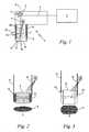
- Fig. 1shows in a schematic longitudinal section illustration an embodiment of a laser system 1 according to the invention for medical removal of body tissue 3 that is schematically indicated in Figs. 4 through 7 .
- the laser system 1comprises of laser source 2, a scanner 7, as well as a guide frame 6.
- the laser source 2generates a laser beam 4 with which in operation body tissue 3 ( Figs. 4 through 7 ) is removed.
- the scanner 7is arranged in the path of the laser beam 4 between the laser source 2 and the guide frame 6.
- the laser beam 4impinges on a mirror 8 of the scanner 7 and is deflected by it by approximately 90 degrees.
- the mirror 8 of the scanner 7is controllable in such a way that the reflected laser beam 4 can be deflected in different directions.
- a base surface 21 of the guide frame 6is scanned by means of the exiting laser beam 4.
- the guide frame 6forms an end 14 of a closed guide tube 15 that guides the laser beam 4 exiting from the scanner 7.
- the guide frame 6 and the guide tube 15are configured as a geometrically right prism with a central axis 9.
- the scanner 7is arranged close to the central axis 9 wherein the central axis 9 in the illustrated embodiment passes through the mirror 8 of the scanner 7.
- the guide frame 6has on the side facing the body tissue 3 to be treated ( Figs. 4 through 7 ) a closed circumferentially extending edge 10 that delimits the base surface 21 of the guide frame 6.
- the edge 10is a pointed edge.
- the guide frame 6has on its inner side 11 a circumferentially extending slanted surface 12 that, beginning at the scanner 7, widens in the radial and axial directions and ends at the pointed edge 10.
- the outer circumferential surface of the guide frame 6 and the guide tube 15is of such a prism shape that its cross-section at any location of the central axis 9 is identical to the base surface 21.
- the base surface 21 of the guide frame 6is completely scanned or illuminated by the laser beam 4 exiting from the mirror 8.
- the laser beamis provided with a focus 19 that, relative to the central axis 9, is at least approximately positioned on the base surface 21 of the guide frame 6.
- the generation of the focus 19is indicated schematically by the schematically shown boundary rays 22 of the laser beam 4.
- a depth markis arranged that will be explained infra in more detail.
- the depth markcan be embodied as a scale or the like and is embodied as a depth stop 13 in the illustrated embodiment.
- the illustration of Fig. 1also shows that in the laser system 1 a schematically illustrated spraying device 18 is provided with which cooling or rinsing water can be sprayed onto the surface to be treated.
- Fig. 2shows in a perspective schematic illustration an embodiment of a cylindrically configured guide frame 6 that has at its end 16 an open support 17.
- the open configuration of the support 17makes it possible to arrange the spraying device 18 externally so that cooling or rinsing liquid can be supplied from the exterior into the interior of the guide frame 6 and thus to the treatment location.
- the cylindrical guide frame 6has a circular disk-shaped base surface 21 that, with regard to its shape, matches exactly a treatment contour 5 of the body tissue 3; this will be explained in more detail infra.
- a base surface 21 and a treatment contour 5 in the form of a polygon, here in an exemplary fashion in the form of an octagonare illustrated.
- any base surface 21 and, as a consequence, any identical treatment contour 5can be pre-selected by means of the geometric configuration of the guide frame 6.
- the embodiments according to Figs. 2 and 3are identical relative one another as well as relative to Fig. 1 .
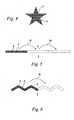
- FIG. 4A schematic plane view of a star shaped guide frame 6 to achieve a star shaped treatment contour 6 is shown as an example in Fig. 4 .
- star shaped or the like holescan be ablated specifically in hard body tissue like bone for the insertion of implants.
- the star shapesupports the mechanical anchorage of the implant in the bone tissue.
- Fig. 5shows a schematic plane view of a rectangular guide frame 5 for performing straight cuts.
- narrow rectangular treatment contours 6can be ablated.
- straight cutscan be performed in the body tissue 3.
- the rectangular guide frame 5may be turned back and forth by a predetermined angle around an axis perpendicular to the treatment contour 6, in order to perform zigzag cuts as shown in Fig. 6 .
- a zigzag shaped guide frame 5 for performing zigzag shaped cutsmay be used, as is schematically shown in Fig. 6 .
- Figs. 7 through 11show as phase images further details of the arrangement according to Fig. 1 and the method steps to be performed therewith.
- the treatment objectiveis to introduce a recess 23 ( Fig. 7 ) or a cut ( Fig. 5, 6 ) into living body tissue 3 in that by means of a laser beam 4 material is removed from the body tissue 3.
- the userdetermines a treatment contour ( Fig. 2 to 6 , 10 , 12 ).
- the recess 23 in this connectionshould have a base surface in the form of the treatment contour 5.
- the body tissue 3can be bone material into which, for example, an implant is to be inserted.
- inventive laser system 1is however not limited to the treatment of bone material as body tissue 3.
- Other hard or soft body tissue 3 of the human body or animal bodycan be treated by means of the inventive laser system 1.
- the laser system 1After selecting a suitable guide frame 6 with regard to its base surface 21 ( Figs. 2, 3 ), the laser system 1 is positioned such that the circumferentially extending edge 10 of the guide frame 6 rests on the surface of the body tissue 3 ( Fig. 7 ).
- the depth stop 13has a spacing relative to the surface of the body tissue 3 in the direction of the central axis 9.
- the laser source 2( Fig. 1 ) is started so that a laser beam 4 is generated.
- the base surface 21 of the guide frame 6is completely scanned or illuminated with the laser beam 4 reflected on the mirror 8.
- the maximum deflection angle ⁇ of the mirror 8is selected such that during the course of the scanning process the laser beam 4 impinges, oriented at a slant outwardly relative to the central axis 9, on the edge 10 of the guide frame 6 which edge is facing the body tissue 3. In the area of the pointed edge 10 this is enabled by the circumferentially extending slanted surface 12 ( Fig. 1 ).
- the guide frame 6 in this connectionis guided by its outer circumferential surface within the outer circumferential surface of the recess 23 in the direction of the central axis 9 and is secured with respect to lateral displacement.
- the control of the advancement of the laser system 1is not realized by means of a predetermined advancing speed. Instead, an at least approximately constant advancing force 20 is provided that acts in the direction of the longitudinal axis 9 on the guide frame 6.
- This advancing force 20can be, for example, the own weight of the laser system 1. Based on the power of the laser beam 4 and the resistance of the body tissue 3 in connection with a constant advancing force 20 a self-regulating advancing speed will result.
- the desired removal depth in the body tissue 3has not been reached.
- the actual reached depthcan be determined with the aid of a depth mark provided on the exterior side of the guide frame 6 or the guide tube 15.
- the depth stop 13still has a spacing from the surface of the body tissue 3.
- the laser beam 4is turned off.
- the laser system 1is removed wherein, in accordance with the illustration of Fig. 10 , the recess 23 with the desired treatment contour 5 according to the base surface 21 of the guide frame 6 ( Figs. 2, 3 , 8 ) is provided in the body tissue 3.
- the recess 23is thus prepared for further treatment, for example, for insertion of an implant.
- Fig. 11shows the arrangement according to Figs. 7 to 9 as the guide frame 6 has reached the predetermined treatment depth, additionally ablating a bottom cavity 25.
- the laser beam 4can be programmed to scan further within the boundaries of the guide frame 6 and recess 23 in a controlled manner in order to make the additional cavity 25 in a programmed shape.
- the role of this cavity 25can be to provide space for bodily liquids and blood when an implant is inserted, or to allow space for the specially shaped implant itself.
- FIG. 12A schematic plane view of a circular shaped guide frame 6 with three spots 26 of the circular treatment contour 5 is shown in Fig. 12 .
- the treatment contour 5is scanned in such a way, that initially three spots 26 located at the borders of the scanned area remain not ablated.
- the guide frameis manually pressed against the three spots 26 to rest against them. These three spots 26 make sure that the guide frame 6 remains perpendicular to the scanned plane throughout the initial scan.
- the three spots 26are ablated last, and the guide frame 6 can be pushed deeper into the body tissue 3 to the bottom of the recess 23. Then the scan procedure is repeated again without remaining spots 26, making use of the recess walls guiding the guide frame 6.
- the scan procedureis repeated again without remaining spots 26, making use of the recess walls guiding the guide frame 6.
- three spots 26are shown. Different quantities of spots 26, at least one spot 26, may be desirable.
- Fig. 13shows in a schematic longitudinal section illustration an alternative embodiment of the invention.
- the laser beam 4is directed by two scanner mirrors 30 and 31 that can rotate around axes that are perpendicular to each other, (or by a single mirror 31 that can rotate freely in all directions) through an optical focusing element 32 either by means of an additional bending mirror 33 or directly into the guide frame 6.
- a protective window 37is arranged on an input side of the guide frame 6, in order to protect the interior of the handpiece with the laser system from debris and liquid, which sprays around during the ablation process of the body tissue 3 ( Fig. 7 to 11 ).
- the guide frame 6 or a handpiece with such a guide frame 6is equipped with additional channels 34, 35, 36 for delivering air and water.
- a cleaning channel 35is provided for delivering water and/or air.
- the delivery direction of said cleaning channel 35is oriented to an output side of the protective window 37, as indicated by an respective arrow.
- the cleaning channel 35can deliver either water or air , or a mixture of both to the protective window 37 in order to clean the window from the debris, and/or to moisturize the debris in order to prevent that the debris is baked to the window by the heat of the laser beam 4.
- an air channel 38is provided, the delivery direction of said air channel 38 being oriented to the treatment area. It can provide air to the ablated area in order to blow the collected water, blood or other bodily fluids away from the treatment site.
- the delivery direction of the cleaning channel 35 and the delivery direction of the air channel 38are crossing each other, as depicted by respective arrows.
- the air flow of the air channel 38can be operated in pulses. When the air is turned off, the water from the cleaning channel 35 is directed to the output surface of the protective window 37. When the air is on, the water gets pulled down by the air to the treatment site.
- a further air channel 36is provided, its delivery direction being oriented generally parallel an across the output surface of the protective window 37.
- the air channel 36can deliver air to the output side surface of the protective window for cleaning the window by blowing away debris and liquid.
Landscapes
- Health & Medical Sciences (AREA)
- Surgery (AREA)
- Physics & Mathematics (AREA)
- Life Sciences & Earth Sciences (AREA)
- Engineering & Computer Science (AREA)
- Medical Informatics (AREA)
- Nuclear Medicine, Radiotherapy & Molecular Imaging (AREA)
- Electromagnetism (AREA)
- Optics & Photonics (AREA)
- Biomedical Technology (AREA)
- Heart & Thoracic Surgery (AREA)
- Otolaryngology (AREA)
- Molecular Biology (AREA)
- Animal Behavior & Ethology (AREA)
- General Health & Medical Sciences (AREA)
- Public Health (AREA)
- Veterinary Medicine (AREA)
- Laser Surgery Devices (AREA)
Abstract
Description
- The invention relates to a laser system for medical removal of body tissue in accordance with the features of the preamble of claim 1.
- Ablation laser systems are described in
WO 97/16126 US 5,474,549 . - Classical surgical means to remove or shape soft or hard human tissue (including but not limited to the osseous (bone) tissue) are mechanical drills and saws. The advantage of these tools is that the surgeon has a very good tactile contact with the treated tissue providing feedback to the surgeon regarding the speed of the procedure and the depth of the drilled hole or the cut.
- The mechanical means are disadvantageous because of the generated heat and thermal damage to the tissue as well as a smear layer that is left on the surface of the treated tissue. This leads to delayed wound healing and compromised blood circulation. In order to minimize thermal damage to the tissue, the holes in the tissue are made by slowly drilling several holes of increasing diameter into the tissue, starting first with a small diameter drill. This makes the procedure very slow and also imprecise. Another disadvantage is the relatively great mechanical pressure that needs to be applied on the tissue in order to perform mechanical tissue removal. Disadvantageous are also the physical limitations with regard to achievable shape or size of the cuts and/or drilled holes. For example, it is not possible to achieve cuts in an exact zig-zag pattern or other pattern that would be desirable e.g. for inserting implants in bone tissue in order to increase the bonding surface area.
- In contrast to conventional mechanical methods, a manually performed non-contact laser surgery allows to ablate tissue in a shape that can be individually adapted to the clinical situation. Moreover, the laser allows arbitrary and sophisticated cut geometries with unprecedented preciseness. In addition, the cuts are clean and without the mechanically and thermally induced smear layer. However, the main disadvantage of laser surgery has been the difficulty in positioning the non-contact laser handpiece on the treated tissue and in obtaining a quick and reliable feedback with regard to the achieved depth of the laser cut or drilled hole. For this reason, laser-assisted surgery has not gained wide acceptance in the medical community.
- The invention has the object to further develop a laser system of the aforementioned kind such that its handling is improved while high efficiency is provided.
- This object is solved by a laser system having the features of claim 1.
- A laser system and a method of operating the laser system are proposed, wherein the laser system has a guide frame in the shape of the treatment contour. Between the laser source and the guide frame, a scanner is arranged in the path of the laser beam for scanning the base surface of the guide frame with the laser beam. In operation, the laser system is placed with its guide frame onto the tissue to be removed. By action of the scanner the base surface of the guide frame is scanned completely by means of the laser beam. The guide frame delimits precisely the surface area that is scanned by the laser beam so that the tissue is removed across the surface area precisely relative to the contour. By means of the guide frame that is in particular guided by hand, the user has direct contact with the surface to be treated. The user can therefore develop a sense for the surface pressure and axial advancing speed. There is a tactile feedback of the treatment progress. The laser beam removes the tissue exactly within the contour that is defined by the guide frame so that the guide frame penetrates also into the tissue with increasing depth of tissue removal. The removed recess provides in this connection a lateral guiding action for the guide frame that can be sensed by the user so that lateral slipping is prevented. Even for great removal depths, the predetermined treatment contour is maintained within the tissue. Handling is significantly facilitated. While providing the greatest possible gentle treatment of the surrounding tissue, it is possible to generate great advancing speeds.
- In a preferred embodiment, a mirror of the scanner is arranged near the central axis of the guide frame wherein a maximum deflection angle of the mirror is adjusted such that the laser beam impinges in a slanted outward direction onto an edge of the guide frame that is facing the body tissue. In this way, it is ensured that the laser beam not only removes tissue within the central area of the base surface of the guide frame but also along the edge of the guide frame. With an appropriate adjustment, the orientation of the laser beam at a slant outwardly has the result that the removed treatment contour is slightly larger than the base surface of the guide frame. In this way it is ensured that the guide frame can penetrate into the recess of the tissue that is being produced with slight oversize.
- In a preferred embodiment, the guide frame has on its inner side a circumferentially extending slanted surface that widens in the radial and axial directions and ends at the pointed edge. In this way, it is ensured that the guide frame does not cover, not even in the edge area, sections of the treatment contour relative to the laser beam. The base surface of the guide frame and the treatment contour match one another with greatest possible precision.
- In an advantageous further embodiment, a focus of the laser beam is positioned at least approximately on the base surface of the guide frame. At its focus, the laser beam has its maximum energy density and thus the greatest removal action. At the exit side of the focus, the energy density and thus also the removal action decrease. In this way, it is achieved that the location of actual tissue removal coincides approximately with the base surface of the guide frame, i.e., it is substantially not advanced relative to the penetration of the guide frame. Geometric deviations between the treatment contour and the base surface of the guide frame that are caused, for example, by angular errors due to the laser beam impinging at a slant across portions are minimized.
- The guide frame has advantageously a depth mark in particular in the form of a depth stop. Based on, for example, a depth scale, the user can check the penetration depth during treatment and, in this way, can check the progress of the treatment. The depth stop can be adjusted at a desired position in order to achieve precisely the predetermined penetration depth without surpassing it or not reaching it.
- In a preferred embodiment, the guide frame forms an end of a closed guide tube that guides the laser beam. In this way, the treatment area is protected from undesirable external influences. Alternatively, it can be expedient to arrange the guide frame at one end of an open support. In this way, the person performing the treatment can perform additional interventions on the treated tissue. For example, rinsing and/or cooling of the treated tissue area with water or other suitable liquids can be done during treatment through an open support. Moreover, a visual control of the treatment surface is possible through the open support and the guide frame.
- In an advantageous embodiment, a protective window is arranged on an input side of the guide frame, and a cleaning channel is provided for delivering water and/or air. The delivery direction of said cleaning channel is oriented to an output side of said protective window. The cleaning channel can deliver either water or air, or a mixture of both to the protective window in order to clean the window from the debris, and/or to moisturize the debris in order to prevent that the debris is baked to the window.
- In a preferred embodiment, an air channel is provided, the delivery direction of said air channel being oriented to the treatment area. The air channel can provide air to the ablated area in order to blow the collected water, blood or other bodily fluids away from the treatment site.
- The delivery direction of said cleaning channel and the delivery direction of said air channel are advantageously crossing each other. When the air is turned off, the water from the cleaning channel is directed to the protective window for cleaning and/or moistening. When the air is on, the water gets pulled down by the air to the treatment site. With a small amount of design and manufacturing effort, numerous different tasks can be performed.
- In an advantageous embodiment, an air channel is provided, the delivery direction of said air channel being oriented generally parallel across the output side of said protective window. The air channel can deliver air to the output side surface of the protective window for cleaning the window by blowing away the debris.
- In a preferred embodiment the guide frame is embodied as a geometric prism. The prism can be an inclined prism which enables a slanted penetration of the guide frame into the body tissue. Preferably, the prism is a right prism so that advancement perpendicular to the base surface of the guide frame is possible. The prism configuration, i.e., a configuration in which the surface area of the transverse section taken along the longitudinal axis remains the same, enables, on the one hand, an unhindered penetration of the guide frame into the body tissue and, on the other hand, results in the circumferential surface of the guide frame resting flat against the circumferential surface of the recess in the body tissue generated by the laser beam. With increasing removal depth the flat contact causes the precision of the guiding action to increase. Great treatment depth can be generated with minimal lateral displacement errors.
- In an advantageous further embodiment, an at least approximately constant advancing force is provided that acts on the guide frame in the direction of its longitudinal axis. This advancing force can be, for example, the weight force of the laser system or a manually applied force exerted by the trained user. During treatment, no advancing speed but only an advancing force is thus exerted. In this way, it is taken into account that the tissue to be removed has in the direction of depth a changing density, hardness or other property that is noticeable as varying removal quantities per time unit. By providing the advancing force as the control parameter, a self-regulating advancing speed that depends on the respective removal progress will be automatically adjusted.
- In a preferred embodiment of the method, after the desired ablation depth and insertion depth of the guide frame into the recess has been reached, an additional bottom cavity is ablated by the laser beam. The cavity provides space for bodily liquids and blood when an implant is inserted, or allows space for the specially shaped implant itself.
- In an advantageous further embodiment, during the initial period of the ablation procedure, the treatment contour is scanned in such a way, that at least one spot located at the border of the treatment contour remains not ablated, and that the guide frame rests on the at least one spot. Preferably in total three spots remain not ablated. During the initial period of the ablation procedure, the recess is not deep enough to sufficiently provide guidance for the guide frame. The spots make sure that the guide frame remains perpendicular to the scanned plane throughout the initial scan. The risk that the recess will not be ablated evenly and that the guide frame will not fall into the recess perpendicularly to the scanned plane is impaired.
- Embodiments of the invention will be explained in more detail in the following with the aid of the drawing. It is shown in:
- Fig. 1
- in a schematic longitudinal section illustration a laser system according to the invention comprising a scanner and a guide frame at the end of a guide tube;
- Fig. 2
- in a perspective schematic illustration a cylindrical guide frame at the end of an open support;
- Fig. 3
- a variant of the arrangement according to
Fig. 2 with a guide frame in the form of a polygon; - Fig. 4
- a schematic plane view of a star shaped guide frame;
- Fig. 5
- a schematic plane view of a rectangular guide frame for performing straight cuts;
- Fig. 6
- a schematic plane view of a zigzag shaped guide frame for performing zigzag shaped cuts;
- Fig. 7
- in a schematic longitudinal section illustration the arrangement according to
Fig. 1 as it is being placed onto body tissue exemplified by bone material; - Fig. 8
- the arrangement according to
Fig. 7 in operation during immersion into the body tissue; - Fig. 9
- the arrangement according to
Figs. 7 and 8 as it reaches the predetermined treatment depth; - Fig. 10
- the body tissue according to
Figs. 7 to 9 with contour-precisely removed material after removal of the laser system; - Fig. 11
- the arrangement according to
Figs. 7 to 9 as it has reached the predetermined treatment depth, additionally ablating a bottom cavity; - Fig. 12
- a schematic plane view of a circular shaped guide frame with three spots of the circular treatment contour remaining not ablated during the initial period of the ablation process;
- Fig. 13
- in a schematic longitudinal section illustration an additional embodiment of the invention comprising multiple scanner mirrors and water-/air-channels in the vicinity of the guide frame.
Fig. 1 shows in a schematic longitudinal section illustration an embodiment of a laser system 1 according to the invention for medical removal ofbody tissue 3 that is schematically indicated inFigs. 4 through 7 . The laser system 1 comprises of laser source 2, ascanner 7, as well as aguide frame 6. The laser source 2 generates alaser beam 4 with which in operation body tissue 3 (Figs. 4 through 7 ) is removed. Thescanner 7 is arranged in the path of thelaser beam 4 between the laser source 2 and theguide frame 6. Thelaser beam 4 impinges on amirror 8 of thescanner 7 and is deflected by it by approximately 90 degrees. Themirror 8 of thescanner 7 is controllable in such a way that the reflectedlaser beam 4 can be deflected in different directions. By an appropriate control of thescanner 7, abase surface 21 of theguide frame 6 is scanned by means of the exitinglaser beam 4.- In the illustrated embodiment, the
guide frame 6 forms anend 14 of aclosed guide tube 15 that guides thelaser beam 4 exiting from thescanner 7. Theguide frame 6 and theguide tube 15 are configured as a geometrically right prism with acentral axis 9. Thescanner 7 is arranged close to thecentral axis 9 wherein thecentral axis 9 in the illustrated embodiment passes through themirror 8 of thescanner 7. - The
guide frame 6 has on the side facing thebody tissue 3 to be treated (Figs. 4 through 7 ) a closed circumferentially extendingedge 10 that delimits thebase surface 21 of theguide frame 6. In the illustrated embodiment theedge 10 is a pointed edge. For this purpose, theguide frame 6 has on its inner side 11 a circumferentially extending slantedsurface 12 that, beginning at thescanner 7, widens in the radial and axial directions and ends at thepointed edge 10. The outer circumferential surface of theguide frame 6 and theguide tube 15 is of such a prism shape that its cross-section at any location of thecentral axis 9 is identical to thebase surface 21. - By a suitable control of the
scanner 7, thebase surface 21 of theguide frame 6 is completely scanned or illuminated by thelaser beam 4 exiting from themirror 8. By means of a non-represented optical device, the laser beam is provided with afocus 19 that, relative to thecentral axis 9, is at least approximately positioned on thebase surface 21 of theguide frame 6. The generation of thefocus 19 is indicated schematically by the schematically shown boundary rays 22 of thelaser beam 4. By actuation of thescanner 7, thefocus 19 migrates on thebase surface 21 without however leaving noticeably thebase surface 21 in the depth direction, i.e., in the direction of thecentral axis 9. - On the exterior circumferential surface of the
guide tube 15 and/or of the guide frame 6 a depth mark is arranged that will be explained infra in more detail. The depth mark can be embodied as a scale or the like and is embodied as adepth stop 13 in the illustrated embodiment. Moreover, the illustration ofFig. 1 also shows that in the laser system 1 a schematically illustratedspraying device 18 is provided with which cooling or rinsing water can be sprayed onto the surface to be treated. Fig. 2 shows in a perspective schematic illustration an embodiment of a cylindrically configuredguide frame 6 that has at itsend 16 anopen support 17. The open configuration of thesupport 17 makes it possible to arrange thespraying device 18 externally so that cooling or rinsing liquid can be supplied from the exterior into the interior of theguide frame 6 and thus to the treatment location.- As in the embodiment according to
Fig. 1 , thecylindrical guide frame 6 has a circular disk-shapedbase surface 21 that, with regard to its shape, matches exactly atreatment contour 5 of thebody tissue 3; this will be explained in more detail infra. In the embodiment according toFig. 3 , for illustrating the principle of the invention, abase surface 21 and atreatment contour 5 in the form of a polygon, here in an exemplary fashion in the form of an octagon, are illustrated. Depending on the treatment objective, almost anybase surface 21 and, as a consequence, anyidentical treatment contour 5 can be pre-selected by means of the geometric configuration of theguide frame 6. In regard to other features and reference numerals, the embodiments according toFigs. 2 and 3 are identical relative one another as well as relative toFig. 1 . - A schematic plane view of a star shaped
guide frame 6 to achieve a star shapedtreatment contour 6 is shown as an example inFig. 4 . With this embodiment, star shaped or the like holes can be ablated specifically in hard body tissue like bone for the insertion of implants. The star shape supports the mechanical anchorage of the implant in the bone tissue. Fig. 5 shows a schematic plane view of arectangular guide frame 5 for performing straight cuts. With the narrowrectangular guide frame 5, narrowrectangular treatment contours 6 can be ablated. By moving and sequentially operating therectangular guide frame 5 as indicated byarrows 24, straight cuts can be performed in thebody tissue 3. Alternatively, therectangular guide frame 5 may be turned back and forth by a predetermined angle around an axis perpendicular to thetreatment contour 6, in order to perform zigzag cuts as shown inFig. 6 . Alternatively, a zigzag shapedguide frame 5 for performing zigzag shaped cuts may be used, as is schematically shown inFig. 6 .Figs. 7 through 11 show as phase images further details of the arrangement according toFig. 1 and the method steps to be performed therewith. The treatment objective is to introduce a recess 23 (Fig. 7 ) or a cut (Fig. 5, 6 ) into livingbody tissue 3 in that by means of alaser beam 4 material is removed from thebody tissue 3. Depending on the type of application, the user determines a treatment contour (Fig. 2 to 6 ,10 ,12 ). Therecess 23 in this connection should have a base surface in the form of thetreatment contour 5. Thebody tissue 3 can be bone material into which, for example, an implant is to be inserted. The recess 23 (Fig. 10 ) is to be generated for this purpose with atreatment contour 5 that should receive the implant with a fit as precise as possible. In order to achieve this, aguide frame 6 with the corresponding identical base surface 21 (Figs. 2, 3 ) is inserted. The application of the inventive laser system 1 is however not limited to the treatment of bone material asbody tissue 3. Other hard orsoft body tissue 3 of the human body or animal body can be treated by means of the inventive laser system 1.- After selecting a
suitable guide frame 6 with regard to its base surface 21 (Figs. 2, 3 ), the laser system 1 is positioned such that thecircumferentially extending edge 10 of theguide frame 6 rests on the surface of the body tissue 3 (Fig. 7 ). In this connection, thedepth stop 13 has a spacing relative to the surface of thebody tissue 3 in the direction of thecentral axis 9. - In accordance with the representation of
Fig. 4 , the laser source 2 (Fig. 1 ) is started so that alaser beam 4 is generated. With a controlled pivoting action of themirror 8, thebase surface 21 of theguide frame 6 is completely scanned or illuminated with thelaser beam 4 reflected on themirror 8. The maximum deflection angle α of themirror 8 is selected such that during the course of the scanning process thelaser beam 4 impinges, oriented at a slant outwardly relative to thecentral axis 9, on theedge 10 of theguide frame 6 which edge is facing thebody tissue 3. In the area of the pointededge 10 this is enabled by the circumferentially extending slanted surface 12 (Fig. 1 ). By means of scanning of theentire base surface 21 with thelaser beam 4 as a result of actuation of thescanner 7, material of the body tissue is completely removed across the entire surface area including the area of theedge 10. This produces arecess 23 illustrated inFig. 10 . The base surface of the recess is identical to thetreatment contour 5 that is predetermined by thebase surface 21 of theguide frame 6. Because thebase surface 21 of theguide frame 6 and the treatment contour 5 (Fig. 10 ) are substantially identical, theguide frame 6 will penetrate by the same amount and with the same speed into thebody tissue 3 as material is removed in the area of therecess 23. According to the illustration ofFig. 8 , it can be seen that theguide frame 6 in this connection is guided by its outer circumferential surface within the outer circumferential surface of therecess 23 in the direction of thecentral axis 9 and is secured with respect to lateral displacement. The control of the advancement of the laser system 1 is not realized by means of a predetermined advancing speed. Instead, an at least approximately constant advancingforce 20 is provided that acts in the direction of thelongitudinal axis 9 on theguide frame 6. This advancingforce 20 can be, for example, the own weight of the laser system 1. Based on the power of thelaser beam 4 and the resistance of thebody tissue 3 in connection with a constant advancing force 20 a self-regulating advancing speed will result. - In accordance with the illustration of
Fig. 8 the desired removal depth in thebody tissue 3 has not been reached. The actual reached depth can be determined with the aid of a depth mark provided on the exterior side of theguide frame 6 or theguide tube 15. Thedepth stop 13 still has a spacing from the surface of thebody tissue 3. As soon as thedepth stop 13 rests against the surface of thebody tissue 3, in accordance with the illustration ofFig. 9 , i.e., the desired treatment depth has been reached, thelaser beam 4 is turned off. Subsequently, the laser system 1 is removed wherein, in accordance with the illustration ofFig. 10 , therecess 23 with the desiredtreatment contour 5 according to thebase surface 21 of the guide frame 6 (Figs. 2, 3 ,8 ) is provided in thebody tissue 3. Therecess 23 is thus prepared for further treatment, for example, for insertion of an implant. Fig. 11 shows the arrangement according toFigs. 7 to 9 as theguide frame 6 has reached the predetermined treatment depth, additionally ablating abottom cavity 25. Thelaser beam 4 can be programmed to scan further within the boundaries of theguide frame 6 andrecess 23 in a controlled manner in order to make theadditional cavity 25 in a programmed shape. The role of thiscavity 25 can be to provide space for bodily liquids and blood when an implant is inserted, or to allow space for the specially shaped implant itself.- A schematic plane view of a circular shaped
guide frame 6 with threespots 26 of thecircular treatment contour 5 is shown inFig. 12 . In laser drilling there is a risk that the recess 23 (Fig. 10 ,11 ) will not be ablated evenly and that theguide frame 6 will not fall into the hole perpendicularly to the scanned plane. As shown inFigure 12 , thetreatment contour 5 is scanned in such a way, that initially threespots 26 located at the borders of the scanned area remain not ablated. The guide frame is manually pressed against the threespots 26 to rest against them. These threespots 26 make sure that theguide frame 6 remains perpendicular to the scanned plane throughout the initial scan. As thewhole treatment contour 5, apart from thespots 26, has been scanned for a while and a certain ablation depth has been achieved, the threespots 26 are ablated last, and theguide frame 6 can be pushed deeper into thebody tissue 3 to the bottom of therecess 23. Then the scan procedure is repeated again without remainingspots 26, making use of the recess walls guiding theguide frame 6. In the preferred embodiment ofFig. 12 threespots 26 are shown. Different quantities ofspots 26, at least onespot 26, may be desirable. Fig. 13 shows in a schematic longitudinal section illustration an alternative embodiment of the invention. In the embodiment depicted inFigure 13 , thelaser beam 4 is directed by two scanner mirrors 30 and 31 that can rotate around axes that are perpendicular to each other, (or by asingle mirror 31 that can rotate freely in all directions) through an optical focusingelement 32 either by means of anadditional bending mirror 33 or directly into theguide frame 6. Aprotective window 37 is arranged on an input side of theguide frame 6, in order to protect the interior of the handpiece with the laser system from debris and liquid, which sprays around during the ablation process of the body tissue 3 (Fig. 7 to 11 ).- The
guide frame 6 or a handpiece with such aguide frame 6 is equipped withadditional channels channel 35 is provided for delivering water and/or air. The delivery direction of said cleaningchannel 35 is oriented to an output side of theprotective window 37, as indicated by an respective arrow. The cleaningchannel 35 can deliver either water or air , or a mixture of both to theprotective window 37 in order to clean the window from the debris, and/or to moisturize the debris in order to prevent that the debris is baked to the window by the heat of thelaser beam 4. - In addition, an
air channel 38 is provided, the delivery direction of saidair channel 38 being oriented to the treatment area. It can provide air to the ablated area in order to blow the collected water, blood or other bodily fluids away from the treatment site. The delivery direction of the cleaningchannel 35 and the delivery direction of theair channel 38 are crossing each other, as depicted by respective arrows. The air flow of theair channel 38 can be operated in pulses. When the air is turned off, the water from the cleaningchannel 35 is directed to the output surface of theprotective window 37. When the air is on, the water gets pulled down by the air to the treatment site. - A
further air channel 36 is provided, its delivery direction being oriented generally parallel an across the output surface of theprotective window 37. Theair channel 36 can deliver air to the output side surface of the protective window for cleaning the window by blowing away debris and liquid. There can also be one or more additional water, air or water/air mixture channels 34, that are directed approximately perpendicular towards the treatment site.
Claims (18)
- A laser system (1) with a laser source (2) for medical removal of body tissue (3) by means of a laser beam (4) within a predetermined treatment contour (5), the laser system (1) comprising a guide frame (6) and a scanner (7), the scanner (7) being arranged between the laser source (2) and the guide frame (6) in the path of the laser beam (4),
characterized in that the guide frame (6) has a base surface (21) matching exactly the shape of the treatment contour (5) andin that the scanner (7) is adapted for completely scanning the base surface (21) of the guide frame (6) by means of the laser beam (4) for removing the body tissue (3), wherein the system is adapted to cause a recess (23) in the body tissue (3) exactly within the contour that is defined by the base surface (21) of the guide frame (6) in such a way, that the guide frame (6) is successively insertable into said recess (23). - The laser system according to claim 1,
characterized in that a mirror (8) of the scanner (7) is arranged near a central axis (9) of the guide frame (6) wherein a maximum deflection angle (α) of the mirror (8) is adjusted such that the laser beam (4), oriented at a slant outwardly, and impinges on an edge (10) of the guide frame (6) which edge is facing the body tissue (3). - The laser system according to claim 2,
characterized in that the edge (10) is pointed, and that the inner side (11) of the guide frame (6) has a circumferentially extending slanted surface (12) widening in the radial and axial directions, which slanted surface (12) ends in the pointed edge (10). - The laser system according to one of the claims 1 to 3,
characterized in that a focus (19) of the laser beam (4) at least approximately is positioned on the base surface (21) of the guide frame (6). - The laser system according to one of the claims 1 to 4,
characterized in that the guide frame (6) has a depth mark, in particular in the form of a depth stop (13). - The laser system according to one of the claims 1 to 5,
characterized in that the guide frame (6) forms an end (14) of a closed guide tube (15) guiding the laser beam (4). - The laser system according to one of the claims 1 to 5,
characterized in that the guide frame (6) is arranged at one end (16) of an open support (17). - The laser system according to one of the claims 1 to 7,
characterized in that a spraying device (18) oriented into the guide frame (6) is provided in particular for cooling and rinsing water. - The laser system according to one of the claims 1 to 8,
characterized in that a protective window (37) is arranged on an input side of the guide frame (6), and that a cleaning channel (35) is provided for delivering water and/or air, the delivery direction of said cleaning channel (35) being oriented to an output side of said protective window (37). - The laser system according to one of the claims 1 to 9,
characterized in that an air channel (38) is provided, the delivery direction of said air channel (38) being oriented to the treatment area. - The laser system according to claims 9 and 10,
characterized in that the delivery direction of said cleaning channel (35) and the delivery direction of said air channel (38) are crossing each other. - The laser system according to one of the claims 9 to 11,
characterized in that an further air channel (36) is provided, the delivery direction of said further air channel (36) being oriented generally parallel across the output side of said protective window (37). - The laser system according to one of the claims 1 to 12,
characterized in that the guide frame (6) is configured as a geometric prism and in particular as a right prism. - The laser system according to one of the claims 1 to 13,
characterized in that an at least approximately constant advancing force (20) is provided that acts on the guide frame (6) in the direction of its longitudinal axis (9). - The laser system according to one of the claims 1 to 14 for medical removal of body tissue (3) by means of the following process steps:- the guide frame (6) is put on a surface of the body tissue (3);- the treatment contour (5) is scanned by the laser beam (4) by means of the scanner (7), resulting in the formation of a recess (23) in the body tissue (3) by ablation of the body tissue (3) in the shape of the treatment contour (5) and the guide frame (6);- successively inserting the guide frame (6) into the recess (23) along with increasing ablation depth until the desired ablation depth has been reached.
- The laser system according to claim 15,characterized in that, after the desired ablation depth and insertion depth of the guide frame (6) into the recess (23) has been reached, an additional bottom cavity (25) is ablated by the laser beam (4).
- The laser system according to claim 15 or 16,characterized in that during the initial period of the ablation procedure, the treatment contour (5) is scanned in such a way, that at least one spot (26) located at the border of the treatment contour (5) remains not ablated, and that the guide frame (6) rests on the at least one spot (26).
- The laser system according to claim 17,characterized in that in total three spots (26) remain not ablated.
Priority Applications (4)
| Application Number | Priority Date | Filing Date | Title |
|---|---|---|---|
| EP07014856AEP2020213B1 (en) | 2007-07-28 | 2007-07-28 | Laser system for medical removal of body tissue |
| DE602007009518TDE602007009518D1 (en) | 2007-07-28 | 2007-07-28 | Laser system for medical removal of body tissue |
| AT07014856TATE482663T1 (en) | 2007-07-28 | 2007-07-28 | LASER SYSTEM FOR MEDICAL REMOVAL OF BODY TISSUE |
| US12/178,979US7867224B2 (en) | 2007-07-28 | 2008-07-24 | Laser system for medical removal of body tissue |
Applications Claiming Priority (1)
| Application Number | Priority Date | Filing Date | Title |
|---|---|---|---|
| EP07014856AEP2020213B1 (en) | 2007-07-28 | 2007-07-28 | Laser system for medical removal of body tissue |
Publications (2)
| Publication Number | Publication Date |
|---|---|
| EP2020213A1 EP2020213A1 (en) | 2009-02-04 |
| EP2020213B1true EP2020213B1 (en) | 2010-09-29 |
Family
ID=38800734
Family Applications (1)
| Application Number | Title | Priority Date | Filing Date |
|---|---|---|---|
| EP07014856ANot-in-forceEP2020213B1 (en) | 2007-07-28 | 2007-07-28 | Laser system for medical removal of body tissue |
Country Status (4)
| Country | Link |
|---|---|
| US (1) | US7867224B2 (en) |
| EP (1) | EP2020213B1 (en) |
| AT (1) | ATE482663T1 (en) |
| DE (1) | DE602007009518D1 (en) |
Families Citing this family (20)
| Publication number | Priority date | Publication date | Assignee | Title |
|---|---|---|---|---|
| US8372061B2 (en)* | 2003-05-15 | 2013-02-12 | Noberto Berna | Treatment tip incision template |
| US10835355B2 (en) | 2006-04-20 | 2020-11-17 | Sonendo, Inc. | Apparatus and methods for treating root canals of teeth |
| SI3311770T1 (en) | 2006-04-20 | 2023-11-30 | Sonendo, Inc. | Apparatus for treating root canals of teeth |
| US12114924B2 (en) | 2006-08-24 | 2024-10-15 | Pipstek, Llc | Treatment system and method |
| US7980854B2 (en) | 2006-08-24 | 2011-07-19 | Medical Dental Advanced Technologies Group, L.L.C. | Dental and medical treatments and procedures |
| CN102724929B (en) | 2009-11-13 | 2016-04-13 | 索南多股份有限公司 | For liquid jet equipment and the method for dental treatment |
| IT1405000B1 (en)* | 2010-02-04 | 2013-12-16 | El En Spa | DEVICE FOR THE TREATMENT OF THE VAGINAL CHANNEL AND ITS APPARATUS |
| US20130190738A1 (en)* | 2010-09-24 | 2013-07-25 | Fotona D.D. | Laser system for the treatment of body tissue |
| CN103347462B (en) | 2010-10-21 | 2017-05-10 | 索南多股份有限公司 | Devices, methods and combinations for endodontics |
| CN110623765A (en) | 2012-03-22 | 2019-12-31 | 索南多股份有限公司 | Apparatus and method for cleaning teeth |
| US10631962B2 (en) | 2012-04-13 | 2020-04-28 | Sonendo, Inc. | Apparatus and methods for cleaning teeth and gingival pockets |
| EP3943042B1 (en) | 2012-12-20 | 2024-03-13 | Sonendo, Inc. | Apparatus for cleaning teeth and root canals |
| US10363120B2 (en) | 2012-12-20 | 2019-07-30 | Sonendo, Inc. | Apparatus and methods for cleaning teeth and root canals |
| EP2991576B1 (en) | 2013-05-01 | 2022-12-28 | Sonendo, Inc. | Apparatus and system for treating teeth |
| US9877801B2 (en) | 2013-06-26 | 2018-01-30 | Sonendo, Inc. | Apparatus and methods for filling teeth and root canals |
| CN104284199B (en)* | 2013-07-11 | 2019-02-01 | Nxp股份有限公司 | Video encoding/decoding method and device are carried out with the deblocking effect operation for reducing complexity |
| US10368083B2 (en)* | 2016-02-15 | 2019-07-30 | Qualcomm Incorporated | Picture order count based motion vector pruning |
| US10806544B2 (en) | 2016-04-04 | 2020-10-20 | Sonendo, Inc. | Systems and methods for removing foreign objects from root canals |
| USD997355S1 (en) | 2020-10-07 | 2023-08-29 | Sonendo, Inc. | Dental treatment instrument |
| EP4604865A2 (en) | 2022-10-20 | 2025-08-27 | Femtovox Incorporated | Apparatus and techniques for surgical laser delivery |
Citations (3)
| Publication number | Priority date | Publication date | Assignee | Title |
|---|---|---|---|---|
| US5474549A (en)* | 1991-07-09 | 1995-12-12 | Laserscope | Method and system for scanning a laser beam for controlled distribution of laser dosage |
| EP0933096A2 (en)* | 1998-01-29 | 1999-08-04 | International Business Machines Corporation | Laser for dermal ablation |
| WO2003041623A1 (en)* | 2001-11-15 | 2003-05-22 | Optotech Ltd. | Non-penetrating filtration surgery |
Family Cites Families (13)
| Publication number | Priority date | Publication date | Assignee | Title |
|---|---|---|---|---|
| US4852551A (en)* | 1988-04-22 | 1989-08-01 | Opielab, Inc. | Contamination-free endoscope valves for use with a disposable endoscope sheath |
| US5575756A (en)* | 1993-08-16 | 1996-11-19 | Olympus Optical Co., Ltd. | Endoscope apparatus |
| US5643253A (en)* | 1995-06-06 | 1997-07-01 | Rare Earth Medical, Inc. | Phototherapy apparatus with integral stopper device |
| DE19510939B4 (en)* | 1995-03-25 | 2004-10-21 | Fotona D.D. | Method for cleaning the exit window of a pulsed laser beam and device for carrying out the method |
| US5860968A (en)* | 1995-11-03 | 1999-01-19 | Luxar Corporation | Laser scanning method and apparatus |
| US5725521A (en)* | 1996-03-29 | 1998-03-10 | Eclipse Surgical Technologies, Inc. | Depth stop apparatus and method for laser-assisted transmyocardial revascularization and other surgical applications |
| DE69812725T2 (en)* | 1997-05-30 | 2003-10-09 | Nidek Co., Ltd. | Laser treatment apparatus |
| DE60001240D1 (en)* | 1999-02-26 | 2003-02-27 | Nidek Kk | Laserdepiliergerät |
| JP2005500108A (en)* | 2001-08-15 | 2005-01-06 | リライアント テクノロジーズ,インコーポレイティド | Apparatus and method for thermal excision of biological tissue |
| ITPD20030102A1 (en)* | 2003-05-15 | 2004-11-16 | Norberto Berna | FORM OF SHAPE AND DEPTH FOR ENGRAVINGS WITH LASER POINTS |
| CN101132831A (en)* | 2005-02-18 | 2008-02-27 | 帕洛玛医疗技术公司 | Dermatological treatment device |
| JP2006289098A (en)* | 2005-04-12 | 2006-10-26 | Inolase 2002 Ltd | Apparatus for vacuum-assisted light-based treatment of skin |
| US20070129775A1 (en)* | 2005-09-19 | 2007-06-07 | Mordaunt David H | System and method for generating treatment patterns |
- 2007
- 2007-07-28EPEP07014856Apatent/EP2020213B1/ennot_activeNot-in-force
- 2007-07-28ATAT07014856Tpatent/ATE482663T1/ennot_activeIP Right Cessation
- 2007-07-28DEDE602007009518Tpatent/DE602007009518D1/enactiveActive
- 2008
- 2008-07-24USUS12/178,979patent/US7867224B2/ennot_activeExpired - Fee Related
Patent Citations (3)
| Publication number | Priority date | Publication date | Assignee | Title |
|---|---|---|---|---|
| US5474549A (en)* | 1991-07-09 | 1995-12-12 | Laserscope | Method and system for scanning a laser beam for controlled distribution of laser dosage |
| EP0933096A2 (en)* | 1998-01-29 | 1999-08-04 | International Business Machines Corporation | Laser for dermal ablation |
| WO2003041623A1 (en)* | 2001-11-15 | 2003-05-22 | Optotech Ltd. | Non-penetrating filtration surgery |
Also Published As
| Publication number | Publication date |
|---|---|
| US7867224B2 (en) | 2011-01-11 |
| EP2020213A1 (en) | 2009-02-04 |
| DE602007009518D1 (en) | 2010-11-11 |
| US20090030408A1 (en) | 2009-01-29 |
| ATE482663T1 (en) | 2010-10-15 |
Similar Documents
| Publication | Publication Date | Title |
|---|---|---|
| EP2020213B1 (en) | Laser system for medical removal of body tissue | |
| AU721565B2 (en) | Combined mechanical/optical system for transmyocardial revascularization | |
| EP2818131B1 (en) | A laser system for the treatment of body tissue | |
| EP2907471B1 (en) | Laser system and method for operating the laser system | |
| US4784135A (en) | Far ultraviolet surgical and dental procedures | |
| EP3223739B1 (en) | Dental laser treatment system | |
| US10292765B2 (en) | Depth controlled photoablation of human or animal tissue | |
| US12137971B2 (en) | System and methods for pulsing and directing a pulsed laser beam to treat dental tissue | |
| US10327832B2 (en) | Methods and devices for tissue ablation | |
| AU7195398A (en) | Laser device with auto-piercing tip for myocardial revascularization procedures | |
| US8372061B2 (en) | Treatment tip incision template | |
| JP2017536142A (en) | Method and apparatus for thermosurgical transpiration and incision of tissue | |
| US20080032251A1 (en) | Laser carious region ablation | |
| KR19990044706A (en) | Laser evaporation apparatus and method of hard tissue | |
| CN107920857B (en) | Bone cutting process | |
| Werner et al. | Co2 laser free form processing of hard tissue | |
| CN116919581A (en) | A system and method for ophthalmic treatment |
Legal Events
| Date | Code | Title | Description |
|---|---|---|---|
| PUAI | Public reference made under article 153(3) epc to a published international application that has entered the european phase | Free format text:ORIGINAL CODE: 0009012 | |
| AK | Designated contracting states | Kind code of ref document:A1 Designated state(s):AT BE BG CH CY CZ DE DK EE ES FI FR GB GR HU IE IS IT LI LT LU LV MC MT NL PL PT RO SE SI SK TR | |
| AX | Request for extension of the european patent | Extension state:AL BA HR MK RS | |
| 17P | Request for examination filed | Effective date:20090731 | |
| AKX | Designation fees paid | Designated state(s):AT BE BG CH CY CZ DE DK EE ES FI FR GB GR HU IE IS IT LI LT LU LV MC MT NL PL PT RO SE SI SK TR | |
| 17Q | First examination report despatched | Effective date:20100115 | |
| GRAP | Despatch of communication of intention to grant a patent | Free format text:ORIGINAL CODE: EPIDOSNIGR1 | |
| GRAS | Grant fee paid | Free format text:ORIGINAL CODE: EPIDOSNIGR3 | |
| GRAA | (expected) grant | Free format text:ORIGINAL CODE: 0009210 | |
| AK | Designated contracting states | Kind code of ref document:B1 Designated state(s):AT BE BG CH CY CZ DE DK EE ES FI FR GB GR HU IE IS IT LI LT LU LV MC MT NL PL PT RO SE SI SK TR | |
| REG | Reference to a national code | Ref country code:GB Ref legal event code:FG4D | |
| REG | Reference to a national code | Ref country code:CH Ref legal event code:EP | |
| REG | Reference to a national code | Ref country code:IE Ref legal event code:FG4D | |
| REF | Corresponds to: | Ref document number:602007009518 Country of ref document:DE Date of ref document:20101111 Kind code of ref document:P | |
| PG25 | Lapsed in a contracting state [announced via postgrant information from national office to epo] | Ref country code:FI Free format text:LAPSE BECAUSE OF FAILURE TO SUBMIT A TRANSLATION OF THE DESCRIPTION OR TO PAY THE FEE WITHIN THE PRESCRIBED TIME-LIMIT Effective date:20100929 Ref country code:AT Free format text:LAPSE BECAUSE OF FAILURE TO SUBMIT A TRANSLATION OF THE DESCRIPTION OR TO PAY THE FEE WITHIN THE PRESCRIBED TIME-LIMIT Effective date:20100929 Ref country code:LT Free format text:LAPSE BECAUSE OF FAILURE TO SUBMIT A TRANSLATION OF THE DESCRIPTION OR TO PAY THE FEE WITHIN THE PRESCRIBED TIME-LIMIT Effective date:20100929 | |
| REG | Reference to a national code | Ref country code:NL Ref legal event code:VDEP Effective date:20100929 | |
| LTIE | Lt: invalidation of european patent or patent extension | Effective date:20100929 | |
| PG25 | Lapsed in a contracting state [announced via postgrant information from national office to epo] | Ref country code:SI Free format text:LAPSE BECAUSE OF FAILURE TO SUBMIT A TRANSLATION OF THE DESCRIPTION OR TO PAY THE FEE WITHIN THE PRESCRIBED TIME-LIMIT Effective date:20100929 | |
| PG25 | Lapsed in a contracting state [announced via postgrant information from national office to epo] | Ref country code:SE Free format text:LAPSE BECAUSE OF FAILURE TO SUBMIT A TRANSLATION OF THE DESCRIPTION OR TO PAY THE FEE WITHIN THE PRESCRIBED TIME-LIMIT Effective date:20100929 Ref country code:GR Free format text:LAPSE BECAUSE OF FAILURE TO SUBMIT A TRANSLATION OF THE DESCRIPTION OR TO PAY THE FEE WITHIN THE PRESCRIBED TIME-LIMIT Effective date:20101230 Ref country code:LV Free format text:LAPSE BECAUSE OF FAILURE TO SUBMIT A TRANSLATION OF THE DESCRIPTION OR TO PAY THE FEE WITHIN THE PRESCRIBED TIME-LIMIT Effective date:20100929 | |
| PG25 | Lapsed in a contracting state [announced via postgrant information from national office to epo] | Ref country code:PT Free format text:LAPSE BECAUSE OF FAILURE TO SUBMIT A TRANSLATION OF THE DESCRIPTION OR TO PAY THE FEE WITHIN THE PRESCRIBED TIME-LIMIT Effective date:20110131 Ref country code:SK Free format text:LAPSE BECAUSE OF FAILURE TO SUBMIT A TRANSLATION OF THE DESCRIPTION OR TO PAY THE FEE WITHIN THE PRESCRIBED TIME-LIMIT Effective date:20100929 Ref country code:IS Free format text:LAPSE BECAUSE OF FAILURE TO SUBMIT A TRANSLATION OF THE DESCRIPTION OR TO PAY THE FEE WITHIN THE PRESCRIBED TIME-LIMIT Effective date:20110129 Ref country code:CZ Free format text:LAPSE BECAUSE OF FAILURE TO SUBMIT A TRANSLATION OF THE DESCRIPTION OR TO PAY THE FEE WITHIN THE PRESCRIBED TIME-LIMIT Effective date:20100929 Ref country code:RO Free format text:LAPSE BECAUSE OF FAILURE TO SUBMIT A TRANSLATION OF THE DESCRIPTION OR TO PAY THE FEE WITHIN THE PRESCRIBED TIME-LIMIT Effective date:20100929 Ref country code:NL Free format text:LAPSE BECAUSE OF FAILURE TO SUBMIT A TRANSLATION OF THE DESCRIPTION OR TO PAY THE FEE WITHIN THE PRESCRIBED TIME-LIMIT Effective date:20100929 Ref country code:EE Free format text:LAPSE BECAUSE OF FAILURE TO SUBMIT A TRANSLATION OF THE DESCRIPTION OR TO PAY THE FEE WITHIN THE PRESCRIBED TIME-LIMIT Effective date:20100929 | |
| PG25 | Lapsed in a contracting state [announced via postgrant information from national office to epo] | Ref country code:BE Free format text:LAPSE BECAUSE OF FAILURE TO SUBMIT A TRANSLATION OF THE DESCRIPTION OR TO PAY THE FEE WITHIN THE PRESCRIBED TIME-LIMIT Effective date:20100929 | |
| PG25 | Lapsed in a contracting state [announced via postgrant information from national office to epo] | Ref country code:ES Free format text:LAPSE BECAUSE OF FAILURE TO SUBMIT A TRANSLATION OF THE DESCRIPTION OR TO PAY THE FEE WITHIN THE PRESCRIBED TIME-LIMIT Effective date:20110109 | |
| PLBE | No opposition filed within time limit | Free format text:ORIGINAL CODE: 0009261 | |
| STAA | Information on the status of an ep patent application or granted ep patent | Free format text:STATUS: NO OPPOSITION FILED WITHIN TIME LIMIT | |
| PG25 | Lapsed in a contracting state [announced via postgrant information from national office to epo] | Ref country code:DK Free format text:LAPSE BECAUSE OF FAILURE TO SUBMIT A TRANSLATION OF THE DESCRIPTION OR TO PAY THE FEE WITHIN THE PRESCRIBED TIME-LIMIT Effective date:20100929 Ref country code:PL Free format text:LAPSE BECAUSE OF FAILURE TO SUBMIT A TRANSLATION OF THE DESCRIPTION OR TO PAY THE FEE WITHIN THE PRESCRIBED TIME-LIMIT Effective date:20100929 | |
| REG | Reference to a national code | Ref country code:DE Ref legal event code:R097 Ref document number:602007009518 Country of ref document:DE Effective date:20110630 | |
| PG25 | Lapsed in a contracting state [announced via postgrant information from national office to epo] | Ref country code:MT Free format text:LAPSE BECAUSE OF FAILURE TO SUBMIT A TRANSLATION OF THE DESCRIPTION OR TO PAY THE FEE WITHIN THE PRESCRIBED TIME-LIMIT Effective date:20100929 | |
| PG25 | Lapsed in a contracting state [announced via postgrant information from national office to epo] | Ref country code:MC Free format text:LAPSE BECAUSE OF NON-PAYMENT OF DUE FEES Effective date:20110731 | |
| REG | Reference to a national code | Ref country code:CH Ref legal event code:PL | |
| REG | Reference to a national code | Ref country code:IE Ref legal event code:MM4A | |
| PG25 | Lapsed in a contracting state [announced via postgrant information from national office to epo] | Ref country code:CH Free format text:LAPSE BECAUSE OF NON-PAYMENT OF DUE FEES Effective date:20110731 Ref country code:LI Free format text:LAPSE BECAUSE OF NON-PAYMENT OF DUE FEES Effective date:20110731 | |
| PG25 | Lapsed in a contracting state [announced via postgrant information from national office to epo] | Ref country code:IE Free format text:LAPSE BECAUSE OF NON-PAYMENT OF DUE FEES Effective date:20110728 | |
| PG25 | Lapsed in a contracting state [announced via postgrant information from national office to epo] | Ref country code:LU Free format text:LAPSE BECAUSE OF NON-PAYMENT OF DUE FEES Effective date:20110728 Ref country code:CY Free format text:LAPSE BECAUSE OF EXPIRATION OF PROTECTION Effective date:20100929 | |
| PG25 | Lapsed in a contracting state [announced via postgrant information from national office to epo] | Ref country code:BG Free format text:LAPSE BECAUSE OF FAILURE TO SUBMIT A TRANSLATION OF THE DESCRIPTION OR TO PAY THE FEE WITHIN THE PRESCRIBED TIME-LIMIT Effective date:20101229 Ref country code:TR Free format text:LAPSE BECAUSE OF FAILURE TO SUBMIT A TRANSLATION OF THE DESCRIPTION OR TO PAY THE FEE WITHIN THE PRESCRIBED TIME-LIMIT Effective date:20100929 | |
| PG25 | Lapsed in a contracting state [announced via postgrant information from national office to epo] | Ref country code:HU Free format text:LAPSE BECAUSE OF FAILURE TO SUBMIT A TRANSLATION OF THE DESCRIPTION OR TO PAY THE FEE WITHIN THE PRESCRIBED TIME-LIMIT Effective date:20100929 | |
| REG | Reference to a national code | Ref country code:FR Ref legal event code:PLFP Year of fee payment:10 | |
| REG | Reference to a national code | Ref country code:FR Ref legal event code:PLFP Year of fee payment:11 | |
| REG | Reference to a national code | Ref country code:FR Ref legal event code:PLFP Year of fee payment:12 | |
| PGFP | Annual fee paid to national office [announced via postgrant information from national office to epo] | Ref country code:FR Payment date:20210728 Year of fee payment:15 | |
| PGFP | Annual fee paid to national office [announced via postgrant information from national office to epo] | Ref country code:DE Payment date:20210721 Year of fee payment:15 Ref country code:GB Payment date:20210722 Year of fee payment:15 | |
| REG | Reference to a national code | Ref country code:DE Ref legal event code:R119 Ref document number:602007009518 Country of ref document:DE | |
| GBPC | Gb: european patent ceased through non-payment of renewal fee | Effective date:20220728 | |
| PG25 | Lapsed in a contracting state [announced via postgrant information from national office to epo] | Ref country code:FR Free format text:LAPSE BECAUSE OF NON-PAYMENT OF DUE FEES Effective date:20220731 | |
| PG25 | Lapsed in a contracting state [announced via postgrant information from national office to epo] | Ref country code:GB Free format text:LAPSE BECAUSE OF NON-PAYMENT OF DUE FEES Effective date:20220728 Ref country code:DE Free format text:LAPSE BECAUSE OF NON-PAYMENT OF DUE FEES Effective date:20230201 | |
| PGFP | Annual fee paid to national office [announced via postgrant information from national office to epo] | Ref country code:IT Payment date:20230724 Year of fee payment:17 | |
| PG25 | Lapsed in a contracting state [announced via postgrant information from national office to epo] | Ref country code:IT Free format text:LAPSE BECAUSE OF NON-PAYMENT OF DUE FEES Effective date:20240728 |