EP2019735B2 - Coating method comprising a flowing coating material - Google Patents
Coating method comprising a flowing coating materialDownload PDFInfo
- Publication number
- EP2019735B2 EP2019735B2EP06818767.3AEP06818767AEP2019735B2EP 2019735 B2EP2019735 B2EP 2019735B2EP 06818767 AEP06818767 AEP 06818767AEP 2019735 B2EP2019735 B2EP 2019735B2
- Authority
- EP
- European Patent Office
- Prior art keywords
- layer
- plastic material
- web
- coating
- applying
- Prior art date
- Legal status (The legal status is an assumption and is not a legal conclusion. Google has not performed a legal analysis and makes no representation as to the accuracy of the status listed.)
- Active
Links
- 239000000463materialSubstances0.000titleclaimsabstractdescription138
- 238000000576coating methodMethods0.000titleclaimsabstractdescription53
- 239000011248coating agentSubstances0.000titleclaimsabstractdescription50
- 239000004033plasticSubstances0.000claimsdescription50
- 229920003023plasticPolymers0.000claimsdescription50
- 239000002245particleSubstances0.000claimsdescription37
- 238000000034methodMethods0.000claimsdescription30
- 238000005299abrasionMethods0.000claimsdescription19
- NIXOWILDQLNWCW-UHFFFAOYSA-MAcrylateChemical compound[O-]C(=O)C=CNIXOWILDQLNWCW-UHFFFAOYSA-M0.000claimsdescription12
- 229910052593corundumInorganic materials0.000claimsdescription11
- 239000010431corundumSubstances0.000claimsdescription11
- 230000009969flowable effectEffects0.000claimsdescription9
- 239000003973paintSubstances0.000claimsdescription8
- 230000005855radiationEffects0.000claimsdescription8
- 238000006116polymerization reactionMethods0.000claimsdescription6
- 230000007717exclusionEffects0.000claimsdescription4
- NIXOWILDQLNWCW-UHFFFAOYSA-NAcrylic acidChemical compoundOC(=O)C=CNIXOWILDQLNWCW-UHFFFAOYSA-N0.000claimsdescription2
- 238000003825pressingMethods0.000claims1
- 238000001035dryingMethods0.000abstractdescription8
- 239000011888foilSubstances0.000abstract5
- 239000012530fluidSubstances0.000abstract1
- 230000032258transportEffects0.000description16
- 239000002023woodSubstances0.000description15
- 239000012876carrier materialSubstances0.000description12
- 239000010408filmSubstances0.000description11
- 239000007788liquidSubstances0.000description9
- 238000004519manufacturing processMethods0.000description7
- 230000008569processEffects0.000description7
- 239000010409thin filmSubstances0.000description6
- 239000004922lacquerSubstances0.000description5
- 230000003287optical effectEffects0.000description5
- 238000006243chemical reactionMethods0.000description4
- 239000000843powderSubstances0.000description4
- 239000007787solidSubstances0.000description4
- 238000004132cross linkingMethods0.000description3
- 238000010894electron beam technologyMethods0.000description3
- 239000011347resinSubstances0.000description3
- 229920005989resinPolymers0.000description3
- 239000003082abrasive agentSubstances0.000description2
- 125000005396acrylic acid ester groupChemical group0.000description2
- 238000005034decorationMethods0.000description2
- 230000000694effectsEffects0.000description2
- 230000006872improvementEffects0.000description2
- 238000005304joiningMethods0.000description2
- 239000000203mixtureSubstances0.000description2
- 238000012805post-processingMethods0.000description2
- 241000894007speciesSpecies0.000description2
- 239000000126substanceSubstances0.000description2
- 239000002966varnishSubstances0.000description2
- SMZOUWXMTYCWNB-UHFFFAOYSA-N2-(2-methoxy-5-methylphenyl)ethanamineChemical compoundCOC1=CC=C(C)C=C1CCNSMZOUWXMTYCWNB-UHFFFAOYSA-N0.000description1
- 239000004925Acrylic resinSubstances0.000description1
- 229920000178Acrylic resinPolymers0.000description1
- 241001136792AlleSpecies0.000description1
- 244000025254Cannabis sativaSpecies0.000description1
- 235000012766Cannabis sativa ssp. sativa var. sativaNutrition0.000description1
- 235000012765Cannabis sativa ssp. sativa var. spontaneaNutrition0.000description1
- 230000009471actionEffects0.000description1
- 239000002390adhesive tapeSubstances0.000description1
- 230000015572biosynthetic processEffects0.000description1
- 235000009120camoNutrition0.000description1
- 235000005607chanvre indienNutrition0.000description1
- 150000001875compoundsChemical class0.000description1
- 239000007799corkSubstances0.000description1
- 238000005520cutting processMethods0.000description1
- 238000000354decomposition reactionMethods0.000description1
- 230000001419dependent effectEffects0.000description1
- 238000001514detection methodMethods0.000description1
- 239000006185dispersionSubstances0.000description1
- 230000005284excitationEffects0.000description1
- 238000007306functionalization reactionMethods0.000description1
- 239000011487hempSubstances0.000description1
- 239000011344liquid materialSubstances0.000description1
- 230000008018meltingEffects0.000description1
- 238000002844meltingMethods0.000description1
- 239000002923metal particleSubstances0.000description1
- 229930014626natural productNatural products0.000description1
- 230000006855networkingEffects0.000description1
- 238000010422paintingMethods0.000description1
- 238000006068polycondensation reactionMethods0.000description1
- 229920000728polyesterPolymers0.000description1
- 229920000642polymerPolymers0.000description1
- 229920002635polyurethanePolymers0.000description1
- 239000004814polyurethaneSubstances0.000description1
- 230000001953sensory effectEffects0.000description1
- 238000007711solidificationMethods0.000description1
- 230000008023solidificationEffects0.000description1
- 210000002268woolAnatomy0.000description1
Images

Classifications
- B—PERFORMING OPERATIONS; TRANSPORTING
- B05—SPRAYING OR ATOMISING IN GENERAL; APPLYING FLUENT MATERIALS TO SURFACES, IN GENERAL
- B05D—PROCESSES FOR APPLYING FLUENT MATERIALS TO SURFACES, IN GENERAL
- B05D7/00—Processes, other than flocking, specially adapted for applying liquids or other fluent materials to particular surfaces or for applying particular liquids or other fluent materials
- B05D7/06—Processes, other than flocking, specially adapted for applying liquids or other fluent materials to particular surfaces or for applying particular liquids or other fluent materials to wood
- B—PERFORMING OPERATIONS; TRANSPORTING
- B05—SPRAYING OR ATOMISING IN GENERAL; APPLYING FLUENT MATERIALS TO SURFACES, IN GENERAL
- B05C—APPARATUS FOR APPLYING FLUENT MATERIALS TO SURFACES, IN GENERAL
- B05C1/00—Apparatus in which liquid or other fluent material is applied to the surface of the work by contact with a member carrying the liquid or other fluent material, e.g. a porous member loaded with a liquid to be applied as a coating
- B05C1/04—Apparatus in which liquid or other fluent material is applied to the surface of the work by contact with a member carrying the liquid or other fluent material, e.g. a porous member loaded with a liquid to be applied as a coating for applying liquid or other fluent material to work of indefinite length
- B05C1/14—Apparatus in which liquid or other fluent material is applied to the surface of the work by contact with a member carrying the liquid or other fluent material, e.g. a porous member loaded with a liquid to be applied as a coating for applying liquid or other fluent material to work of indefinite length using a travelling band
- B—PERFORMING OPERATIONS; TRANSPORTING
- B05—SPRAYING OR ATOMISING IN GENERAL; APPLYING FLUENT MATERIALS TO SURFACES, IN GENERAL
- B05D—PROCESSES FOR APPLYING FLUENT MATERIALS TO SURFACES, IN GENERAL
- B05D3/00—Pretreatment of surfaces to which liquids or other fluent materials are to be applied; After-treatment of applied coatings, e.g. intermediate treating of an applied coating preparatory to subsequent applications of liquids or other fluent materials
- B05D3/06—Pretreatment of surfaces to which liquids or other fluent materials are to be applied; After-treatment of applied coatings, e.g. intermediate treating of an applied coating preparatory to subsequent applications of liquids or other fluent materials by exposure to radiation
- B05D3/061—Pretreatment of surfaces to which liquids or other fluent materials are to be applied; After-treatment of applied coatings, e.g. intermediate treating of an applied coating preparatory to subsequent applications of liquids or other fluent materials by exposure to radiation using U.V.
- B05D3/065—After-treatment
- B05D3/067—Curing or cross-linking the coating
- B—PERFORMING OPERATIONS; TRANSPORTING
- B05—SPRAYING OR ATOMISING IN GENERAL; APPLYING FLUENT MATERIALS TO SURFACES, IN GENERAL
- B05D—PROCESSES FOR APPLYING FLUENT MATERIALS TO SURFACES, IN GENERAL
- B05D7/00—Processes, other than flocking, specially adapted for applying liquids or other fluent materials to particular surfaces or for applying particular liquids or other fluent materials
- B05D7/50—Multilayers
- B05D7/52—Two layers
- B05D7/54—No clear coat specified
- B05D7/542—No clear coat specified the two layers being cured or baked together
- E—FIXED CONSTRUCTIONS
- E04—BUILDING
- E04F—FINISHING WORK ON BUILDINGS, e.g. STAIRS, FLOORS
- E04F13/00—Coverings or linings, e.g. for walls or ceilings
- E04F13/07—Coverings or linings, e.g. for walls or ceilings composed of covering or lining elements; Sub-structures therefor; Fastening means therefor
- E04F13/08—Coverings or linings, e.g. for walls or ceilings composed of covering or lining elements; Sub-structures therefor; Fastening means therefor composed of a plurality of similar covering or lining elements
- E04F13/10—Coverings or linings, e.g. for walls or ceilings composed of covering or lining elements; Sub-structures therefor; Fastening means therefor composed of a plurality of similar covering or lining elements of wood or with an outer layer of wood
- E—FIXED CONSTRUCTIONS
- E04—BUILDING
- E04F—FINISHING WORK ON BUILDINGS, e.g. STAIRS, FLOORS
- E04F15/00—Flooring
- E04F15/02—Flooring or floor layers composed of a number of similar elements
- E04F15/04—Flooring or floor layers composed of a number of similar elements only of wood or with a top layer of wood, e.g. with wooden or metal connecting members
- E04F15/045—Layered panels only of wood
- B—PERFORMING OPERATIONS; TRANSPORTING
- B05—SPRAYING OR ATOMISING IN GENERAL; APPLYING FLUENT MATERIALS TO SURFACES, IN GENERAL
- B05C—APPARATUS FOR APPLYING FLUENT MATERIALS TO SURFACES, IN GENERAL
- B05C1/00—Apparatus in which liquid or other fluent material is applied to the surface of the work by contact with a member carrying the liquid or other fluent material, e.g. a porous member loaded with a liquid to be applied as a coating
- B05C1/003—Apparatus in which liquid or other fluent material is applied to the surface of the work by contact with a member carrying the liquid or other fluent material, e.g. a porous member loaded with a liquid to be applied as a coating incorporating means for heating or cooling the liquid or other fluent material
- B—PERFORMING OPERATIONS; TRANSPORTING
- B05—SPRAYING OR ATOMISING IN GENERAL; APPLYING FLUENT MATERIALS TO SURFACES, IN GENERAL
- B05D—PROCESSES FOR APPLYING FLUENT MATERIALS TO SURFACES, IN GENERAL
- B05D2252/00—Sheets
- B05D2252/04—Sheets of definite length in a continuous process
- Y—GENERAL TAGGING OF NEW TECHNOLOGICAL DEVELOPMENTS; GENERAL TAGGING OF CROSS-SECTIONAL TECHNOLOGIES SPANNING OVER SEVERAL SECTIONS OF THE IPC; TECHNICAL SUBJECTS COVERED BY FORMER USPC CROSS-REFERENCE ART COLLECTIONS [XRACs] AND DIGESTS
- Y10—TECHNICAL SUBJECTS COVERED BY FORMER USPC
- Y10T—TECHNICAL SUBJECTS COVERED BY FORMER US CLASSIFICATION
- Y10T156/00—Adhesive bonding and miscellaneous chemical manufacture
- Y10T156/10—Methods of surface bonding and/or assembly therefor
- Y10T156/1002—Methods of surface bonding and/or assembly therefor with permanent bending or reshaping or surface deformation of self sustaining lamina
- Y—GENERAL TAGGING OF NEW TECHNOLOGICAL DEVELOPMENTS; GENERAL TAGGING OF CROSS-SECTIONAL TECHNOLOGIES SPANNING OVER SEVERAL SECTIONS OF THE IPC; TECHNICAL SUBJECTS COVERED BY FORMER USPC CROSS-REFERENCE ART COLLECTIONS [XRACs] AND DIGESTS
- Y10—TECHNICAL SUBJECTS COVERED BY FORMER USPC
- Y10T—TECHNICAL SUBJECTS COVERED BY FORMER US CLASSIFICATION
- Y10T428/00—Stock material or miscellaneous articles
- Y10T428/31504—Composite [nonstructural laminate]
- Y10T428/31971—Of carbohydrate
- Y10T428/31989—Of wood
Definitions
- the inventionrelates to a method for the coating of boards, in particular of wood-based panels for the production of floor panels, with a flowable coating material.
- Laminate panelsessentially consist of an approx. 6 to 8 mm thick base plate made of MDF or HDF material, to which a decor paper layer is glued. The decor paper layer is impregnated with a resin and is usually further provided with abrasion-resistant particles.
- the application of pressure and heathardens the resin, resulting in an extremely abrasion-resistant and decorative surface.
- wood-based panelssuch as wood-based panels.
- MDF or HDFto be printed directly with a plastic material, i. without the use of a decorative paper.
- the e.g. Milled MDF boardand provided with a primer.
- a colored decorationis printed, e.g. a wood decor.
- a plurality of very thin material layersare applied, wherein the individual material layers are cured in each case before the application of the next layer.
- the material layersare e.g.
- the resulting overall layerthus has a layered structure. Between the individual layers arise interfaces in which no good networking takes place.
- the individual layersusually have a thickness of 10 to 15 .mu.m and usually 5 to 7 layers are applied one above the other, resulting in a total thickness of the thin-layer system or layer stack of about 50-105 .mu.m.
- U1is a device for the coating of plates in the run out.
- Several platesare arranged on a conveyor belt, which are fed one after the other, inter alia coating stations.
- Such a coating stationcomprises an applicator roll, with which a lacquer is applied to a plate.
- an applicator rollwith which a lacquer is applied to a plate.
- the applicator rollmay include a textured surface to pattern lacquer on the surface of a plate.
- lacqueris applied in a structured manner to a surface of a plate by means of a jet printing technique, which is especially widespread in inkjet printers. This is followed, in turn, by a post-processing device with which the coating can be cured.
- filled paintcan be used. These are paints which contain extremely fine solid particles such as corundum with diameters in the nanometer range.
- From the DE 103 58 190 A1is a method for controlling printing presses out. With the device known therefrom furniture panels are printed.
- a device suitable for carrying out the method according to the invention and not belonging to the inventioncomprises transport means for the transport of plates.
- the devicecomprises means for supplying coating material to the plate surface. Subsequent to the feeding means, means for drying and / or curing the coating material are provided above the plate.
- the apparatuscomprises means for passing a web of material between the transport means for the transport of boards and the means for drying and / or curing.
- the surface of the coating materialcan be provided with a structure without having to exert high pressure, since the coating material is dried and / or cured in this state. So succeeds the coating of a plate with a textured surface, without this as in the publication DE 20 2004 018 710 U1 known prior art either have to use a press or a complex printing unit. Also, a multi-step coating can thus be uniformly dried and / or cured in one operation. Above all, it is possible that a chemical network extends through the entire structure of the layer, resulting in a particularly stable coating.
- drying and / or curing under exclusion of airis possible. Drying and / or curing under exclusion of air is frequently desired, for example in order to achieve particularly high crosslinking in the case of curing of a varnish with UV light, ie a particularly high conversion of double bonds within the varnish. In the case of curing with electron beams, an air seal is usually required.
- the inventionrelates to a method for coating a wood-based panel, in particular a particleboard, MDF or HDF board, with a flowable plastic material.
- the processrelates to the production of panels, e.g. the production of floor panels.
- a thick layer of at least 30 microns of a plastic materialis applied to the wood-based panel in a single step.
- the plastic materialis preferably transparent at least after drying or curing.
- the layeris preferably applied in a single operation in a thickness of 30 to 150 microns, more preferably applied in a thickness of 80 to 110 microns and most preferably in a thickness of about 95 microns.
- the layer of plastic materialis cured.
- a single thick layerinstead of a series of many thin layers has a number of advantages.
- larger abrasion resistant particlessuch as e.g. Larger corundum particles are provided, as it is possible in a thin-film system.
- the individual thin layersonly have a thickness of 10 to 15 .mu.m, and which are cured one after the other, in fact only relatively small particles can be used, since the particles are preferably incorporated as far as possible in the layers should be.
- the flowable plastic materialis an acrylate system.
- an acrylate systemis meant, for example, a polymerizable mixture of double bond-containing mono-, di- and polyfunctional acrylic acid-based compounds.
- Typical representativesare for example Dipropylenglycoldiacrylat, 1,6-Hexandioldiacrylat, polyurethane acrylic acid ester, polyester acrylic acid ester as they are available in the production program of the company BASF under the trade name Laromer TM types on the market.
- the plastic materialis accordingly a polymerizable acrylate system.
- the plastic material, ie the polymerizable acrylate system according to the inventiona curable with UV radiation plastic.
- the UV radiationserves to start the polymerization. Since the polymerization can be stopped at any time, it is thus possible to produce a crosslinking gradient and thus a hardening gradient in the single thick layer, which may be, for example, 95 ⁇ m.
- the curing gradientis generated over a single, over the entire layer thickness occurring polymerization with the highest possible conversion.
- ⁇ layersare applied wet on wet (for example primer, acrylate (roll application), corundum, topcoat application) and polymerized in a single step, preferably by UV excitation.
- the acrylate layeris cured according to the invention in a single thick layer.
- the individual layersdiffer in their function and thus also in the chemical structure:
- the primerhas the task of producing good adhesion between the printing and the plastic layer.
- the middle layeris flexibly adjusted to relieve internal stresses and avoid embrittlement and to absorb impact energy when walking when the coated board is e.g. is used as a floor panel.
- the Toplack Anlagenis modified so that it leads to high hardness and scratch resistance.
- the polymerizationis carried out so that a nearly complete double bond conversion over the entire layer is achieved.
- the primeris preferably designed so that better adhesion is achieved by greater functionalization of the acrylate mixture.
- the middle layerhas chain growth and only minor cross-linking.
- the topcoat layerpreferably contains a highly crosslinkable acrylate system.
- abrasion-resistant particlesin particular corundum particles, are preferably introduced into the layer. Since the layer is very thick, it is possible to incorporate relatively thick particles which have better abrasion properties than smaller particles.
- Corundum particlesin a range from DF 220 to DF 280 according to FEPA specification (Federation of European Producers of Abrasives) used. These then have an average particle size D50 of 36.5 to 63.0 ⁇ m. More preferably, particles in the range of DF 240 to DF 280 are used, i. with particle sizes D50 from 44.5 to 36.5 ⁇ m.
- relatively small particlessuch as corundum particles
- the particle sizeis usually in the range of DF 320 to DF 500 according to the FEPA specification. That is, the previously usable grain sizes of the abrasion-resistant particles were limited to average grain size D50 of 29.2 to 12.8 ⁇ m.
- These relatively small particlesresult in lower levels of abrasion for the same additional amount, i.
- a larger amount of weightmust be used for finer particles than for larger particles.
- finer particleslead to a poorer transparency of the surface and graying phenomena.
- the introduction of the particles into the layercan be carried out after application of the layer in which the particles are sprinkled, for example, on the not yet cured layer. After the particles have sunk or pressed into the layer, the material is cured so that the particles are firmly entrapped in the layer. Another possibility is to introduce the particles before the application of the layer in the flowable plastic material, for example in the form of a dispersion.
- a material web having a structured surfaceis applied to the layer of plastic material.
- a structureis embossed in the layer of plastic material. Since the layer is still liquid at this time, virtually no pressure needs to be expended.
- the layer of plastic materialis dried and / or cured, whereby the introduced into the layer of plastic material structure is fixed. Thereafter, in a further step, the material web with structured surface can be removed again.
- a pattern rollis used to emboss a structure in the layer of plastic material. This in turn happens after the application of the plastic material to the plate but before the curing of the plastic material.
- the layer of plastic materialis dried and / or hardened, whereby the structure introduced into the layer of plastic material is fixed. Due to the thickness of the layer according to the invention, structure depths of 0 to 80 ⁇ m are possible. Structural depths of from 20 to 80 ⁇ m and particularly preferably up to about 35 ⁇ m are particularly preferred. In the prior art, in which a layer system of individual thin films was used, it was not possible to produce structure depths of more than 5 to 10 microns. These small structure depths are not sufficient for many purposes. For example, to realize a realistic real wood imitation, deeper structures must be imprinted into the layer.
- a smooth-surfaced webwill be applied to the layer of plastic material without exerting much pressure. In this way it is prevented that air gets to the plastic material.
- the layer of plastic materialis dried and / or cured in the absence of air.
- the material web with a smooth surfaceis removed again.
- the material webs usedare preferably permeable to UV light. If a UV-curable plastic is used, it is thus possible to cure the plastic, although it is covered by the material web.
- the associated feeding devicecomprises a collecting device for the coating material, which is arranged adjacent to the transport means for the transport of the plates.
- the collecting devicefurther adjoins a roller for transporting the material web.
- the collecting deviceis designed so that liquid, located in the catcher coating material flows to the roller. It is thus achieved that, given a sufficiently large filling of the collecting device, liquid coating material can completely coat a material web with a liquid film when a material web is transported over the roller. Overall, it can be achieved with sufficient supply of liquid coating material that the liquid coating material completely fills the space between the surface of a plate and the material web located above it. It then gets very reliable no air in the area, a hardening can be carried out so particularly reliable under exclusion of air.
- relatively thick paint layershaving a total thickness of, for example, 80 to 100 ⁇ m in thickness and to uniformly dry and cure.
- Thismakes it possible to embed relatively thick abrasion-resistant particles such as corundum with a diameter of up to 100 ⁇ m within the paint. Since the abrasion resistance increases with the diameter of the abrasion-resistant particles, a relatively high abrasion resistance can be achieved. Nevertheless, as the diameter of the abrasion-resistant particles increases, the amount of abrasive material can also be reduced. This achieves both an improvement in abrasion values and an improvement in the transparency of the abrasion-resistant coating.
- the thickness of the layeris preferably 30 to 150 ⁇ m, more preferably 80 to 110 ⁇ m.
- the e.g. Devicecomprises the means for transporting plates a circulating conveyor belt, on which the plates are stored for transport.
- foreign materialsare introduced into the layer, for example, interspersed, for example, to achieve an aesthetically pleasing effect.
- the foreign materialsare preferably natural materials such as cork or hemp, but also plastics and metal particles are suitable.
- the foreign materialscan be introduced in such a way that they partially protrude from the layer in relief, or else that they have completely sunk into the layer.
- the layeris preferably transparent, so that the foreign bodies therein are visible. For example, leaves or tree needles can be inserted into the liquid material layer, which are preferably completely sunk in and surrounded by the layer. Subsequently, the transparent layer is cured. Since the e.g.
- Natural materials completely surrounded by the layerwhich may be an acrylic resin, for example, and are thus protected from the air and the weather, there is no decomposition of natural products.
- a treated plate, with a transparent hard plastic layer in which foreign materials are introducedcan thus have an aesthetically very appealing effect.
- Other conceivable materialsare, for example, leaves, twigs, branches or wool. The introduction of foreign materials is made possible by the relatively large thickness of the layer.
- the associated material webis unrolled from a roll, passed over other rollers parallel to the surface of plates, which are transported, and then rolled up again by a roller.
- an exchange of the material webis sufficient if a surface structure is to be changed or if a structure on the material web has damage, for example due to signs of wear.
- a consistent quality of a generated surface structurecan also be ensured, since, in contrast to a roll with a structured surface, with the unrolling of the material web, the quality of the surface of the material web which produces the structure is not changed.
- the structure in the surface of the coatingis generated virtually without pressure, so that the surface of the material web is subject to practically no signs of wear for this reason.
- the associated rollers for the transport of a Material webarranged so that they are similar to the catcher in cross section a funnel.
- the supply of coating material to the surface of a platethen finally takes place via a gap. This ensures the proper supply of coating material between the web and surface of the plate to be coated further improved.
- the width of the aforementioned gapcan be changed. This serves to control the amount of coating material which is fed to the surface of a plate. Also, in one embodiment, the gap may be closed so as to control the timing of delivery.
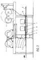
- FIG. 1shows the eg, not belonging to the invention device with which a support material 6, such as a chip, MDF or HDF plate can be coated in a continuous, as coating materials are preferably UV or electron beam crosslinkable, flowable systems of suitable viscosity used.
- a carrier material 6is supplied and coated with a flowable material 8.
- the coatingtakes place via a collecting device 5, which adjoins a roller 4.
- a web-shaped materialnamely a UV-transparent and / or electron-permeable and radiation-resistant film 3, is guided over the roller 4.
- the filmhas a smooth surface facing the coating material 8 when the coating 8 is to have a smooth surface.
- the corresponding surface of the film 3is structured if the coating 8 is to have a structured surface.
- the web-shaped material or the film 3is unrolled from a supply roll or supply roll 1 and finally rolled up again on a roll 2. Between the roller 1 and the roller 4, along the transport path for the sheet material 3, there are three further relatively small diameter rollers serving to guide the sheet material.
- the small diameter feeding roller 13is disposed adjacent to the roller 4. causes together with the roller 4 that the web-like material together with the catcher 5 forms a funnel-shaped inlet for coating material 8.
- the coating material 8, such as a paintis suitably brought between the carrier material 6 and sheet material 3 via this funnel shape ,
- the funnel-shaped inletopens into a gap.
- the gap widthcan be changed to control the supply of coating material.
- the roller 4 and the roller 2there are four further guide rollers of relatively small diameter, which serve to guide the sheet material from the roller 4 to the roller 2, the first guide roller 10 - seen from the roller 4 in the transport direction of the sheet material - causes together with the roller 4 that the web-like material is guided parallel to the surface of the carrier material 6.
- the film 3 means 7with which the underlying coating material can be dried and / or cured. These are above all devices for curing with UV light or electron beams.
- a web-shaped smooth or structured material 3is aligned at the same time from the supply roll 1 both in the longitudinal direction and in the transverse direction and applied synchronously to the carrier material 6 by means of the roller 4 and the catcher 5 on the still liquid coating material.
- the aim of the orientation of the web-shaped materialis to synchronize certain points of the carrier material 6 with certain points of the web-like material fitting one above the other.
- the speed of a carrier material or a plate 6is measured with measuring devices in an embodiment of the invention.
- optical measuring devicesare used to determine the speed of the carrier material, For example, by means of electronic or magnetic sensors, the rotational speed of at least one Roll involved in the transport of the sheet material is detected.
- the thus obtained information about the transport speed of each plate 6 and transport speed of the sheet materialare used for the control.
- the two speedsare thus controlled so that a plate is brought together defined with the web-like material, so as to be able to structure a surface targeted.
- the web-shaped materialfor example, optical markings, which are detected by optical sensors.
- the transport of the sheet material and / or the transport of the plates 6are controlled so that a plate is coated in dependence on such an optical marking and the coating is structured in dependence on these optical markings.
- the carrier material with the liquid coating material and the overlying sheet-like materialthen passes through the curing station 7, in which the liquid coating material 8 is crosslinked and goes into a solid state.
- the surface structure of the web-like materialis fixed and imaged in the hardened layer.
- the sheet-like materialis removed from the cured solid coating material and wound up again into a roll.
- FIG. 2shown embodiment provided that a plurality of supply rolls 1 and take-up rolls 2 are present for the web-like material.
- the supply rolls and the take-up rollscan be endlessly connected to each other during production by a device without stop.
- connectionis made for reasons of practicality, preferably at speeds up to 120 m / min.
- the respective at rest film receiving stationis charged with a roll of web-like material and prepared the automatic connection by a double-sided adhesive tape is glued to the web start.
- the beginning of the sheet materialis inserted into a gap, which serves to connect. Through this gap at the same time the web-like material is guided, which is currently being unrolled.
- the triggering of the connectionis done automatically by electronically detecting the running meter of the roll from which web-shaped material is unrolled, or sensory detection of the associated end of a web-shaped material.
- the running web-like materialis stored in a dancer device operating as a web store.
- the driven rolleris reduced to a speed of about 15 m / min.
- the missing length of the web-like material to the line speedpulls out of the dancer.
- the corresponding film rollaccelerates again up to the maximum speed, for example 120 m / min, until the dancer roll has returned to its working
- the automatic connection devicecomprises at least two unwind stations with flap bearings and pneumatic tension shafts.
- the unwindingis done by a servomotor.
- Meansare available to automatically adjust cars with the films or web-like materials.
- the actual connecting devicecomprises four pneumatically operated mangle rolls. There are also two separating knives for cutting off the sheet material after bonding.
- An automatic braking force regulation of the unwinding rollsis available. This includes dancer rollers, pneumatic proportional linear cylinders with guide and guide rollers and an automatic crack control.
- the carrier material or a plate 6is first passed through the two superimposed, rotating rollers 4 and 11 passed through and transported. From here, the carrier material 6 reaches a conveyor belt 1 2, which further transports the carrier material. The web-shaped material or the film 3 and the carrier material 6 are transported at the same speed.
- the distance between the two rollers 4 and 11can be changed in order to vary the thickness of the coating can.
- the height of the guide roller 10can be changed in order to influence the thickness of the coating can.
Landscapes
- Engineering & Computer Science (AREA)
- Life Sciences & Earth Sciences (AREA)
- Wood Science & Technology (AREA)
- Architecture (AREA)
- Civil Engineering (AREA)
- Structural Engineering (AREA)
- Physics & Mathematics (AREA)
- Plasma & Fusion (AREA)
- Application Of Or Painting With Fluid Materials (AREA)
- Coating Apparatus (AREA)
- Laminated Bodies (AREA)
- Paints Or Removers (AREA)
- Floor Finish (AREA)
- Chemical And Physical Treatments For Wood And The Like (AREA)
Abstract
Description
Translated fromGermanDie Erfindung betrifft ein Verfahren für die Beschichtung von Platten, insbesondere von Holzwerkstoffplatten zur Herstellung von Fußbodenpaneelen, mit einem fließfähigem Beschichtungsmaterial.The invention relates to a method for the coating of boards, in particular of wood-based panels for the production of floor panels, with a flowable coating material.
Aus dem Stand der Technik ist eine Reihe von Holzwerkstoffplatten zur Herstellung von Fußbodenpaneelen bekannt. Platten aus Massivholz haben eine ästhetisch besonders ansprechende Oberfläche sind jedoch sehr teuer. Aus diesem Grund wurden Furnierplatten entwickelt, die eine Grundplatte aus einem relativ kostengünstigen Holzwerkstoff aufweisen, wie zum Beispiel eine kostengünstige Holzart, auf die eine dünne Furnierschicht einer hochwertigeren Holzart aufgebracht wird. Jedoch sind auch Furnierplatten immer noch relativ teuer, so dass viele Verbraucher Laminatpaneele bevorzugen. Laminatpaneele bestehen im Wesentlichen aus einer ca. 6 bis 8 mm dicken Grundplatte aus MDF- oder HDF-Material auf die eine Dekorpapierschicht aufgeklebt ist. Die Dekorpapierschicht ist mit einem Harz imprägniert und ist in der Regel weiter mit abriebfesten Partikeln versehen. Bei der Herstellung der Laminatpaneele wird durch die Anwendung von Druck und Hitze das Harz ausgehärtet und es entsteht eine extrem abriebfeste und dekorative Oberfläche. In neuester Zeit wurden neue Verfahren entwickelt, um Holzwerkstoffplatten, wie z.B. MDF oder HDF, direkt mit einem Kunststoffmaterial zu bedrucken, d.h. ohne die Verwendung eines Dekorpapiers. Zu diesem Zweck wird die z.B. MDF-Platte abgeschliffen und mit einer Grundierung versehen. Auf diese Grundierung wird in einem zweiten Schritt ein farbliches Dekor aufgedruckt, z.B. ein Holzdekor. Danach werden eine Vielzahl von sehr dünnen Materialschichten aufgebracht, wobei die einzelnen Materialschichten vor dem Auftragen der nächsten Schicht jeweils ausgehärtet werden. Die Materialschichten sind z.B. mehrere, im Wesentlichen durchsichtige Lackschichten aus einem aushärtbaren Kunststoff. Die resultierende Gesamtschicht hat somit einen schichtweisen Aufbau. Zwischen den einzelnen Schichten entstehen Grenzflächen, in denen keine gute Vernetzung stattfindet. Die einzelnen Schichten haben üblicherweise eine Dicke von 10 bis 15 µm und es werden üblicherweise 5 bis 7 Schichten übereinander aufgetragen, so dass sich eine Gesamtstärke des Dünnschichtsystems oder Schichtstapels von ca. 50-105 µm ergibt.From the prior art, a number of wood-based panels for the production of floor panels is known. Solid wood panels have an aesthetically pleasing surface but are very expensive. For this reason, veneer boards have been developed which have a base plate made of a relatively inexpensive wood material, such as an inexpensive wood species, to which a thin veneer layer of a higher quality wood species is applied. However, veneer sheets are still relatively expensive, so many consumers prefer laminate panels. Laminate panels essentially consist of an approx. 6 to 8 mm thick base plate made of MDF or HDF material, to which a decor paper layer is glued. The decor paper layer is impregnated with a resin and is usually further provided with abrasion-resistant particles. In the manufacture of the laminate panels, the application of pressure and heat hardens the resin, resulting in an extremely abrasion-resistant and decorative surface. Recently, new processes have been developed to produce wood-based panels, such as wood-based panels. MDF or HDF to be printed directly with a plastic material, i. without the use of a decorative paper. For this purpose, the e.g. Milled MDF board and provided with a primer. On this primer, in a second step, a colored decoration is printed, e.g. a wood decor. Thereafter, a plurality of very thin material layers are applied, wherein the individual material layers are cured in each case before the application of the next layer. The material layers are e.g. several, substantially transparent lacquer layers of a hardenable plastic. The resulting overall layer thus has a layered structure. Between the individual layers arise interfaces in which no good networking takes place. The individual layers usually have a thickness of 10 to 15 .mu.m and usually 5 to 7 layers are applied one above the other, resulting in a total thickness of the thin-layer system or layer stack of about 50-105 .mu.m.
Aus der Druckschrift
Aus der Druckschrift
Aus der
Aus der Druckschrift
sogenannter gefüllter Lack verwendet werden. Hierunter sind solche Lacke zu verstehen, die extrem feine Festkörperpartikel wie Korund mit Durchmessern im Nanometerbereich enthalten.so-called filled paint can be used. These are paints which contain extremely fine solid particles such as corundum with diameters in the nanometer range.
Aus der
Es ist die Aufgabe der Erfindung ein neues Verfahren zu schaffen, mit dem eine schnelle und kostengünstige Beschichtung von Platten, insbesondere für die Herstellung von Fußbodenpaneelen, in guter Qualität möglich ist.It is the object of the invention to provide a new method with which a fast and cost-effective coating of plates, in particular for the production of floor panels, in good quality is possible.
Diese und andere Ziele, welche aus der folgenden Beschreibung hervorgehen, werden durch die vorliegende Erfindung , die durch die technischen Merkmale und Verfahrensschritte des unabhängigen Anspruchs 1 definiert ist, gelöst. Weitere technischen Merkmale und Verfahrensschnitte sind in den abhängigen Ansprüchen angegeben.These and other objects, which will become apparent from the following description, are achieved by the present invention, which is defined by the technical features and method steps of independent claim 1. Further technical features and method sections are specified in the dependent claims.
Zur Lösung der Aufgabe umfasst eine zur Durchführung des erfindungsgemäßen Verfahrens geeignete, nicht zur Erfindung gehörende Vorrichtung Transportmittel für den Transport von Platten. Die Vorrichtung umfasst eine Zuführungseinrichtung, mit der Beschichtungsmaterial auf die Plattenoberfläche gebracht werden kann, Im Anschluss an die Zuführungseinrichtung sind oberhalb der Platte Mittel für das Trocknen und / oder Harten des Beschichtungsmaterials vorgesehen. Im Unterschied zum eingangs genannten Stand der Technik
Wird eine Materialbahn mit strukturierter Oberfläche eingesetzt, so kann die Oberfläche des Beschichtungsmaterials mit einer Struktur versehen werden, ohne großen Druck ausüben zu müssen, da das Beschichtungsmaterial in diesem Zustand getrocknet und/ oder gehärtet wird. Gelingt so das Beschichten einer Platte mit strukturierter Oberfläche, ohne hierfür wie beim aus der Druckschrift
Wird eine Materialbahn mit glatter Oberfläche eingesetzt, so ist so ein Trocknen und / oder Härten unter Luftabschluss möglich. Ein Trocknen und / oder Härten unter Luftabschluss ist vielfach gewünscht, so zum Beispiel um im Fall einer Härtung eines Lacks mit UV-Licht eine besonders große Vernetzung, also einen besonders großen Umsatz an Doppelbindungen innerhalb des Lacks zu erzielen. Im Fall einer Härtung mit Elektronenstrahlen ist ein Luftabschluss in der Regel erforderlich.If a material web with a smooth surface is used, so drying and / or curing under exclusion of air is possible. Drying and / or curing under exclusion of air is frequently desired, for example in order to achieve particularly high crosslinking in the case of curing of a varnish with UV light, ie a particularly high conversion of double bonds within the varnish. In the case of curing with electron beams, an air seal is usually required.
Die Erfindung betrifft ein Verfahren zur Beschichtung einer Holzwerkstoffplatte, insbesondere einer Span-, MDF- oder HDF-Platte, mit einem fließfähigen Kunststoffmaterial. Insbesondere betrifft das Verfahren die Herstellung von Paneelen, wie z.B. die Herstellung von Fußbodenpaneelen. Bei diesem Verfahren wird in einem einzigen Arbeitsschritt eine dicke Schicht von mind. 30 µm aus einem Kunststoffmaterial auf die Holzwerkstoffplatte aufgetragen. Das Kunststoffmaterial ist zumindest nach dem Austrocknen oder Härten vorzugweise durchsichtig. Die Schicht wird in einem einzigen Arbeitsgang vorzugsweise in einer Dicke von 30 bis 150 µm aufgetragen, besonders bevorzugt in einer Dicke von 80 bis 110 µm und insbesondere bevorzugt in einer Dicke von etwa 95 µm aufgetragen. In einem weiteren Schritt wird die Schicht aus Kunststoffmaterial ausgehärtet. Die Verwendung einer einzelnen dicken Schicht anstelle einer Folge von vielen dünnen Schichten hat eine Reihe von Vorteilen. Zum einen können größere abriebfeste Partikel, wie z.B. größere Korundpartikel, vorgesehen werden, als es bei einem Dünnschichtsystem möglich ist. Bei den Dünnschichtsystemen, in denen die einzelnen dünnen Schichten nur eine Dicke von 10 bis 15 µm haben, und die jeweils für sich nacheinander ausgehärtet werden, können nämlich nur relativ kleine Partikel verwendet werden, da die Partikel vorzugsweise so weit wie möglich in den Schichten eingebunden sein sollten.The invention relates to a method for coating a wood-based panel, in particular a particleboard, MDF or HDF board, with a flowable plastic material. In particular, the process relates to the production of panels, e.g. the production of floor panels. In this process, a thick layer of at least 30 microns of a plastic material is applied to the wood-based panel in a single step. The plastic material is preferably transparent at least after drying or curing. The layer is preferably applied in a single operation in a thickness of 30 to 150 microns, more preferably applied in a thickness of 80 to 110 microns and most preferably in a thickness of about 95 microns. In a further step, the layer of plastic material is cured. The use of a single thick layer instead of a series of many thin layers has a number of advantages. First, larger abrasion resistant particles, such as e.g. Larger corundum particles are provided, as it is possible in a thin-film system. In the thin-film systems in which the individual thin layers only have a thickness of 10 to 15 .mu.m, and which are cured one after the other, in fact only relatively small particles can be used, since the particles are preferably incorporated as far as possible in the layers should be.
Das fließfähige Kunststoffmaterial ist ein Acrylatsystem. Unter einem Acrylatsystem wird hierin beispielsweise ein polymerisationsfähiges Gemisch von doppelbindungshaltigen mono-, di- und mehrfachfunktionellen acrylsäurebasierenden Verbindungen verstanden. Typische Vertreter sind beispielsweise Dipropylenglycoldiacrylat, 1,6-Hexandioldiacrylat, Polyurethan-Acrylsäureester, Polyester-Acrylsäurester wie sie im Produktionsprogramm der Firma BASF unter dem Handelsnamen Laromer™ - Typen am Markt erhältlich sind.The flowable plastic material is an acrylate system. By an acrylate system is meant, for example, a polymerizable mixture of double bond-containing mono-, di- and polyfunctional acrylic acid-based compounds. Typical representatives are for example Dipropylenglycoldiacrylat, 1,6-Hexandioldiacrylat, polyurethane acrylic acid ester, polyester acrylic acid ester as they are available in the production program of the company BASF under the trade name Laromer™ types on the market.
Die Holzwerkstoffplatte wird vor der Beschichtung mit dem fließfähigen Kunststoffmaterial vorzugsweise mit einem farbigen Dekordruck versehen, wie z.B. mit einem Holzdekor. Das Kunststoffmaterial wird über den Dekordruck aufgetragen und ist vorzugsweise möglichst durchsichtig. Das Verfahren kann dabei beispielsweise wie folgt ablaufen:
- Zuerst wird die Trägerplatte, wie z.B. eine MDF-Platte, feingeschliffen und ausgerichtet bzw. kalibriert. Danach wird ein Primer aufgebracht und vorzugweise eine Grundierung aufgetragen. Anschließend erfolgt der Druck des Dekors auf den Primer bzw. die Grundierung. In einem weiteren Schritt wird ein weiterer Primer aufgetragen, der vorzugweise ein geeigneter Primer für die folgende Schicht aus Kunststoffmaterial ist. Dieser Primer wird vorzugsweise in einer Menge von bis zu 10 g/m2, besonders bevorzugt von etwa 5 g/m2 aufgetragen. Auf den Primer wird dann eine einzelne dicke Schicht eines Acrylatsystems durch z.B. Walzenauftrag aufgebracht. Dies geschieht vorzugsweise in einer Menge von bis zu 100 g/m2, besonders bevorzugt von etwa 65 g/m2. Auf das noch nicht gehärtete Acrylatsystem werden dann vorzugsweise Korundpartikel gestreut und zwar je nach geforderter Abriebklasse bis zu 70 g/m2, bevorzugt 45 g/m2. Über diese Schicht erfolgt dann ein Toplackauftrag über eine Strukturgeberfolie mit bevorzugt 2-100 g/m2, besonders bevorzugt 30 g/m2. Zum Schluss werden dann alle Schichten in einem einzigen Arbeitsgang vorzugsweise mittels UV - Strahlung durchgehärtet. Das gehärtete Acrylatsystem ist vorzugweise möglichst durchsichtig, damit der darunterliegende Dekordruck sichtbar ist.
- First, the carrier plate, such as an MDF plate, is honed and aligned or calibrated. Thereafter, a primer is applied and preferably applied a primer. Subsequently, the decoration is printed on the primer or the primer. In a further step, a further primer is applied, which is preferably a suitable primer for the following layer of plastic material. This primer is preferably applied in an amount of up to 10 g / m2 , more preferably of about 5 g / m2 . A single thick layer of an acrylate system is then applied to the primer by roll application, for example. This is preferably done in an amount of up to 100 g / m2 , more preferably of about 65 g / m2 . Corundum particles are then preferably scattered onto the not yet cured acrylate system, depending on the required abrasion class, up to 70 g / m2 , preferably 45 g / m2 . A topcoat application is then effected via this layer by means of a pattern-forming film with preferably 2-100 g / m2 , more preferably 30 g / m2 . Finally, all layers are then cured in a single operation, preferably by means of UV radiation. The cured acrylate system is preferably as transparent as possible, so that the underlying decorative pressure is visible.
Die Aushärtung des Kunststoffmaterials erfolgt über eine Polymerisation des Kunststoffmaterials und nicht über eine Polykondensation. Das Kunststoffmaterial ist dementsprechend ein polymerisationsfähiges Acrylatsystem. Besonders bevorzugt ist das Kunststoffmaterial, d.h. das erfindungsgemäß polymerisationsfähige Acrylatsystem, ein mit UV-Strahlen aushärtbarer Kunststoff. Dabei dient die UV-Strahlung dazu, die Polymerisation zu starten. Da die Polymerisation jederzeit gestoppt werden kann ist es somit möglich in der einzelnen dicken Schicht, die z.B. 95 µm betragen kann, einen Vernetzungsgradienten und damit einen Härtungsgradienten herzustellen. Der Härtungsgradient wird über eine einmalige, über die gesamte Schichtstärke stattfindende Polymerisation mit möglichst vollständigem Umsatz erzeugt. Dies steht im Gegensatz zum Lackieren mit vielen Dünnschichten, wobei diese Schicht für Schicht aufgetragen und dann mittels Strahlung "angeliert" werden, d.h. es wird vorzeitig die Reaktion abgebrochen. Damit hat man über den gesamten Querschnitt aller Schichten keine durchgehende Polymerbildung sondern Grenzschichten.The curing of the plastic material via a polymerization of the plastic material and not via a polycondensation. The plastic material is accordingly a polymerizable acrylate system. Particularly preferred is the plastic material, ie the polymerizable acrylate system according to the invention, a curable with UV radiation plastic. The UV radiation serves to start the polymerization. Since the polymerization can be stopped at any time, it is thus possible to produce a crosslinking gradient and thus a hardening gradient in the single thick layer, which may be, for example, 95 μm. The curing gradient is generated over a single, over the entire layer thickness occurring polymerization with the highest possible conversion. This is in contrast to painting with many thin films, which are applied layer by layer and then "annealed" by means of radiation, ie it is prematurely terminated the reaction. Thus, over the entire cross-section of all layers, there is no continuous polymer formation but boundary layers.
In einer vorteilhaften Weiterbildung des Verfahrens werden nass in nass mehrere Schichten aufgetragen (wie z.B. Primer, Acrylat (Walzenauftrag), Korund; Toplackauftrag) und in einem einzigen Schritt vorzugsweise durch UV - Anregung polymerisiert. Die Acrylatschicht wird dabei erfindungsgemäß in einer einzelnen dicken Schicht gehärtet. Die einzelnen Schichten unterscheiden sich in ihrer Funktion und damit auch im chemischen Aufbau: Der Primer hat die Aufgabe, eine gute Haftung zwischen Druck- und Kunststoffschicht herzustellen. Die mittlere Schicht ist flexibel eingestellt, um innere Spannungen abzubauen und eine Versprödung zu vermeiden sowie Stoßenergie beim Begehen abzufangen, wenn die beschichtete Platte z.B. als Fußbodenpaneel verwendet wird. Die Toplackschicht hingegen ist so modifiziert, dass sie zu hoher Härte und Kratzfestigkeit führt. Da es beim Nass- in Nassauftrag zu Durchmischungen der Schichten kommt, gibt es keine Grenzschichten sondern tatsächlich einen Härtegradienten von oben nach unten. Chemisch zusammengefasst: Die Polymerisation wird so durchgeführt, dass ein nahezu vollständiger Doppelbindungsumsatz über die gesamte Schicht erreicht wird. Der Primer ist vorzugsweise so ausgelegt, dass durch stärkere Funktionalisierung der Acrylatmischung ein besseres Haften erreicht wird. Die mittlere Schicht weist insbesondere Kettenwachstum und nur geringfügigere Vernetzung auf. Die Toplackschicht enthält vorzugsweise ein hochvemetzungsfähiges Acrylatsystem.In an advantageous development of the process, several layers are applied wet on wet (for example primer, acrylate (roll application), corundum, topcoat application) and polymerized in a single step, preferably by UV excitation. The acrylate layer is cured according to the invention in a single thick layer. The individual layers differ in their function and thus also in the chemical structure: The primer has the task of producing good adhesion between the printing and the plastic layer. The middle layer is flexibly adjusted to relieve internal stresses and avoid embrittlement and to absorb impact energy when walking when the coated board is e.g. is used as a floor panel. The Toplackschicht, however, is modified so that it leads to high hardness and scratch resistance. Since the wet-to-wet application causes intermixing of the layers, there are no boundary layers but actually a hardness gradient from top to bottom. Chemically summarized: The polymerization is carried out so that a nearly complete double bond conversion over the entire layer is achieved. The primer is preferably designed so that better adhesion is achieved by greater functionalization of the acrylate mixture. In particular, the middle layer has chain growth and only minor cross-linking. The topcoat layer preferably contains a highly crosslinkable acrylate system.
Um die Abriebfestigkeit der Schicht zu erhöhen werden vorzugsweise abriebfeste Partikel, insbesondere Korundpartikel, in die Schicht eingebracht. Da die Schicht sehr dick ist, ist es möglich relativ dicke Partikel einzubringen, die bessere Abriebeigenschaften mit sich bringen, als kleinere Partikel. Abhängig von der verwendeten Schichtdicke werden somit z.B. Korundpartikel in einem Bereich von DF 220 bis DF 280 nach FEPA-Spezifikation (Federation of European Producers of Abrasives) eingesetzt. Diese haben dann eine Durchschnittskorngröße D50 von 36,5 bis 63,0 µm. Besonders bevorzugt werden Partikel im Bereich von DF 240 bis DF 280 verwendet, d.h. mit Korngrößen D50 von 44,5 bis 36,5 µm. Bei den Eingangs erwähnten Schichtsystemen mit mehreren dünnen Einzelschichten (sogenannte Dünnschichtsysteme), die übereinander aufgetragen werden, müssen relativ kleine Partikel (wie z.B. Korund-Partikel) verwendet werden, da diese ansonsten zu weit aus den einzelnen Schichten hervorstehen würden. Die Partikelgröße liegt dabei üblicherweise im Bereich von DF 320 bis DF 500 nach FEPA-Spezifikation. Das heißt, die bisher verwendbaren Korngrößen der abriebfesten Partikel waren auf eine Durchschnittskomgröße D50 von 29,2 bis 12,8 µm beschränkt. Diese relativ kleinen Partikel führen bei gleicher Zusätzmenge zu niedrigeren Abriebwerten, d.h. bei gleicher Abriebklasse muss bei feineren Partikeln eine größere Gewichtsmenge verwendet werden, als bei größeren Partikeln. Außerdem führen feinere Partikel zu einer schlechteren Transparenz der Oberfläche und zu Vergrauungserscheinungen.In order to increase the abrasion resistance of the layer, abrasion-resistant particles, in particular corundum particles, are preferably introduced into the layer. Since the layer is very thick, it is possible to incorporate relatively thick particles which have better abrasion properties than smaller particles. Depending on the layer thickness used, e.g. Corundum particles in a range from DF 220 to DF 280 according to FEPA specification (Federation of European Producers of Abrasives) used. These then have an average particle size D50 of 36.5 to 63.0 μm. More preferably, particles in the range of DF 240 to DF 280 are used, i. with particle sizes D50 from 44.5 to 36.5 μm. In the above-mentioned multi-layered thin film systems (so-called thin-film systems) applied to one another, relatively small particles (such as corundum particles) must be used, otherwise they would protrude too far from the individual layers. The particle size is usually in the range of DF 320 to DF 500 according to the FEPA specification. That is, the previously usable grain sizes of the abrasion-resistant particles were limited to average grain size D50 of 29.2 to 12.8 μm. These relatively small particles result in lower levels of abrasion for the same additional amount, i. For the same abrasion class, a larger amount of weight must be used for finer particles than for larger particles. In addition, finer particles lead to a poorer transparency of the surface and graying phenomena.
Das Einbringen der Partikel in die Schicht kann nach Auftragen der Schicht erfolgen, in dem die Partikel zum Beispiel auf die noch nicht ausgehärtete Schicht aufgestreut werden. Nachdem die Partikel in die Schicht eingesunken sind oder eingepresst wurden, wird das Material ausgehärtet, so dass die Partikel fest in der Schicht eingeschlossen werden. Eine andere Möglichkeit besteht darin, die Partikel vor dem Auftragen der Schicht in das fließfähige Kunststoffmaterial einzubringen, zum Beispiel in Form einer Dispersion.The introduction of the particles into the layer can be carried out after application of the layer in which the particles are sprinkled, for example, on the not yet cured layer. After the particles have sunk or pressed into the layer, the material is cured so that the particles are firmly entrapped in the layer. Another possibility is to introduce the particles before the application of the layer in the flowable plastic material, for example in the form of a dispersion.
In einer Variante der Erfindung wird vor dem Aushärtungsschritt, also nachdem die Schicht auf die Platte aufgetragen wurde, eine Materialbahn mit strukturierter Oberfläche, praktisch ohne Druck auszuüben, auf die Schicht aus Kunststoffmaterial aufgebracht. Auf diese Weise wird eine Struktur in die Schicht aus Kunststoffmaterial eingeprägt. Da die Schicht zu diesem Zeitpunkt noch flüssig ist, muss praktisch kein Druck aufgewendet werden. In einem nächsten Schritt wird die Schicht aus Kunststoffmaterial getrocknet und / oder gehärtet, wodurch die in die Schicht aus Kunststoffmaterial eingebrachte Struktur fixiert wird. Danach kann in einem weiteren Schritt die Materialbahn mit strukturierter Oberfläche wieder entfernt werden. In einem alternativen Verfahren wird eine Strukturwalze verwendet, um eine Struktur in die Schicht aus Kunststoffmaterial einzuprägen. Dies geschieht wiederum nach dem Auftragen des Kunststoffmaterials auf die Platte aber vor dem Aushärten des Kunststoffmaterials. Möglichst direkt nach dem Aufprägen der Struktur wird in einem nächsten Schritt die Schicht aus Kunststoffmaterial getrocknet und /oder gehärtet, wodurch die in die Schicht aus Kunststoffmaterial eingebrachte Struktur fixiert wird. Aufgrund der erfindungsgemäß großen Dicke der Schicht sind Strukturtiefen von 0 bis zu 80 µm möglich. Besonders bevorzugt sind Strukturtiefen von 20 bis zu 80 µm und besonders bevorzugt von bis zu ca. 35 µm. Im Stand der Technik, bei dem ein Schichtsystem von einzelnen Dünnschichten verwendet wurde, war es bisher nicht möglich Strukturtiefen von mehr als 5 bis 10 µm zu erzeugen. Diese geringen Strukturtiefen sind für viele Zwecke nicht ausreichend. Um z.B. eine realistische Echtholz-Nachahmung zu realisieren, müssen tiefere Strukturen in die Schicht eingeprägt werden. Mit den sehr tiefen Strukturen gemäß dem vorliegenden Verfahren können daher Muster und Strukturen in die Schicht eingebracht werden, die ästhetisch besonders ansprechend sind und bisher nicht möglich waren. Eine Strukturtiefe von 35 µm ist deutlich fühlbar und mit dem bloßen Auge sichtbar und eignet sich besonders, um die Struktur von Echtholzböden nachzuahmen.In a variant of the invention, prior to the curing step, ie after the layer has been applied to the plate, a material web having a structured surface, virtually without pressure, is applied to the layer of plastic material. In this way, a structure is embossed in the layer of plastic material. Since the layer is still liquid at this time, virtually no pressure needs to be expended. In a next step, the layer of plastic material is dried and / or cured, whereby the introduced into the layer of plastic material structure is fixed. Thereafter, in a further step, the material web with structured surface can be removed again. In an alternative method, a pattern roll is used to emboss a structure in the layer of plastic material. This in turn happens after the application of the plastic material to the plate but before the curing of the plastic material. If possible directly after the structure has been impressed, in a next step the layer of plastic material is dried and / or hardened, whereby the structure introduced into the layer of plastic material is fixed. Due to the thickness of the layer according to the invention, structure depths of 0 to 80 μm are possible. Structural depths of from 20 to 80 μm and particularly preferably up to about 35 μm are particularly preferred. In the prior art, in which a layer system of individual thin films was used, it was not possible to produce structure depths of more than 5 to 10 microns. These small structure depths are not sufficient for many purposes. For example, to realize a realistic real wood imitation, deeper structures must be imprinted into the layer. Therefore, with the very deep structures of the present method, patterns and structures that are aesthetically pleasing and not heretofore possible can be incorporated into the layer. A texture depth of 35 microns is clearly felt and visible to the naked eye and is particularly suitable to imitate the structure of real wood floors.
In einer alternativen Ausführungsform der Erfindung wird eine Materialbahn mit glatter Oberfläche ohne größeren Druck auszuüben auf die Schicht auf Kunststoffmaterial gelegt. Auf diese Weise wird verhindert, dass Luft an das Kunststoffmaterial gelangt. In einem nächsten Schritt wird die Schicht aus Kunststoffmaterial unter Luftabschluss getrocknet und / oder gehärtet. In einem weiteren Schritt wird die Materialbahn mit glatter Oberfläche wieder entfernt.In an alternative embodiment of the invention, a smooth-surfaced web will be applied to the layer of plastic material without exerting much pressure. In this way it is prevented that air gets to the plastic material. In a next step, the layer of plastic material is dried and / or cured in the absence of air. In a further step, the material web with a smooth surface is removed again.
Die verwendeten Materialbahnen, ob mit glatter oder strukturierter Oberfläche, sind vorzugsweise für UV-Licht durchlässig. Wenn ein UV aushärtbarer Kunststoff verwendet wird, ist es somit möglich den Kunststoff auszuhärten, obwohl dieser von der Materialbahn abgedeckt ist.The material webs used, whether with a smooth or structured surface, are preferably permeable to UV light. If a UV-curable plastic is used, it is thus possible to cure the plastic, although it is covered by the material web.
In einer Ausführungsform der o.g. Vorrichtung umfasst die dazu gehörende Zuführungseinrichtung eine Auffangeinrichtung für das Beschichtungsmaterial, die angrenzend an die Transportmittel für den Transport der Platten angeordnet ist. Die Auffangeinrichtung grenzt des Weiteren an eine Walze für den Transport der Materialbahn an. Die Auffangeinrichtung ist so beschaffen, dass flüssiges, in der Auffangeinrichtung befindliches Beschichtungsmaterial zur Walze fließt. Es wird so erreicht, dass bei hinreichend großer Befüllung der Auffangeinrichtung flüssiges Beschichtungsmaterial vollständig eine Materialbahn mit einem Flüssigkeitsfilm zu überziehen vermag, wenn eine Materialbahn über die Walze transportiert wird. Insgesamt kann so bei hinreichender Zufuhr von flüssigem Beschichtungsmaterial erreicht werden, dass das flüssige Beschichtungsmaterial vollständig den Raum zwischen der Oberfläche einer Platte und der darüber befindlichen Materialbahn ausfüllt. Es gelangt dann besonders zuverlässig keine Luft in den Bereich, Eine Härtung kann so besonders zuverlässig unter Luftabschluss durchgeführt werden.In one embodiment of the above-mentioned. The associated feeding device comprises a collecting device for the coating material, which is arranged adjacent to the transport means for the transport of the plates. The collecting device further adjoins a roller for transporting the material web. The collecting device is designed so that liquid, located in the catcher coating material flows to the roller. It is thus achieved that, given a sufficiently large filling of the collecting device, liquid coating material can completely coat a material web with a liquid film when a material web is transported over the roller. Overall, it can be achieved with sufficient supply of liquid coating material that the liquid coating material completely fills the space between the surface of a plate and the material web located above it. It then gets very reliable no air in the area, a hardening can be carried out so particularly reliable under exclusion of air.
Auch ist es bei dieser Ausführungsform möglich, relativ dicke Lackschichten mit einer Gesamtdicke von beispielsweise 80 bis 100 µm Dicke aufzutragen und einheitlich zu trocknen sowie zu härten. Dies wiederum ermöglicht es, relativ dicke abriebfeste Partikel wie Korund mit einem Durchmesser von bis zu 100 µm innerhalb des Lacks einzubetten. Da mit dem Durchmesser der abriebfesten Partikel die Abriebfestigkeit zunimmt, kann so eine relativ hohe Abriebfestigkeit erreicht werden. Mit zunehmendem Durchmesser der abriebfesten Partikel kann zugleich dennoch auch die Menge an Abriebmaterial gesenkt werden. Es gelingt so sowohl eine Verbesserung von Abriebwerten als auch eine Verbesserung der Transparenz der abriebfesten Beschichtung.Also, in this embodiment, it is possible to apply relatively thick paint layers having a total thickness of, for example, 80 to 100 μm in thickness and to uniformly dry and cure. This in turn makes it possible to embed relatively thick abrasion-resistant particles such as corundum with a diameter of up to 100 μm within the paint. Since the abrasion resistance increases with the diameter of the abrasion-resistant particles, a relatively high abrasion resistance can be achieved. Nevertheless, as the diameter of the abrasion-resistant particles increases, the amount of abrasive material can also be reduced. This achieves both an improvement in abrasion values and an improvement in the transparency of the abrasion-resistant coating.
Besonders bevorzugt sind Partikelkomgrößen von DF 220 bis DF 280 FEPA. Die Dicke der Schicht beträgt vorzugsweise 30 bis 150 µm, besonders bevorzugt 80 bis 110 µm.Particle sizes of DF 220 to DF 280 FEPA are particularly preferred. The thickness of the layer is preferably 30 to 150 μm, more preferably 80 to 110 μm.
In einer Ausführungsform der e.g. Vorrichtung umfassen die Mittel für den Transport von Platten ein umlaufendes Transportband, auf das die Platten für den Transport abgelegt werden.In an embodiment of the e.g. Device comprises the means for transporting plates a circulating conveyor belt, on which the plates are stored for transport.
In einer bevorzugten Weiterbildung des Verfahrens werden nach dem Auftragen der Schicht aus Kunststoffmaterial, aber vor dem Aushärten oder Trocknen derselben, Fremdmaterialien in die Schicht eingebracht, zum Beispiel eingestreut, um beispielsweise einen ästhetisch ansprechenden Effekt zu erzielen. Die Fremdmaterialien sind bevorzugt Naturstoffe wie Kork oder Hanf, aber auch Kunststoffe und Metallpartikel sind geeignet. Die Fremdmaterialien können so eingebracht werden, dass sie zum Teil reliefartig aus der Schicht hervorstehen oder aber so, dass sie vollständig in der Schicht eingesunken sind. Die Schicht ist dabei vorzugsweise durchsichtig, so dass die darin befindlichen Fremdkörper sichtbar sind. Zum Beispiel können in die flüssige Materialschicht Blätter oder Baumnadeln eingelegt werden, die vorzugsweise vollständig in der Schicht eingesunken und von dieser umgeben sind. Anschließend wird die durchsichtige Schicht ausgehärtet. Da die z.B. Naturmaterialien völlig von der Schicht, die zum Beispiel ein Acrylharz sein kann, umgeben sind und damit vor Luft und Witterungseinflüssen geschützt sind, findet kein Zerfall der Naturstoffe statt. Eine derartig behandelte Platte, mit einer durchsichtigen harten Kunststoffschicht, in der Fremdmaterialien eingebracht sind, kann somit einen ästhetisch äußerst ansprechenden Effekt haben. Weitere denkbare Materialien sind zum Beispiel Laub, Zweige, Äste oder Wolle. Das Einbringen von Fremdmaterialien wird durch die relativ große Dicke der Schicht ermöglicht.In a preferred embodiment of the method, after the application of the layer of plastic material, but before the curing or drying of the same, foreign materials are introduced into the layer, for example, interspersed, for example, to achieve an aesthetically pleasing effect. The foreign materials are preferably natural materials such as cork or hemp, but also plastics and metal particles are suitable. The foreign materials can be introduced in such a way that they partially protrude from the layer in relief, or else that they have completely sunk into the layer. The layer is preferably transparent, so that the foreign bodies therein are visible. For example, leaves or tree needles can be inserted into the liquid material layer, which are preferably completely sunk in and surrounded by the layer. Subsequently, the transparent layer is cured. Since the e.g. Natural materials completely surrounded by the layer, which may be an acrylic resin, for example, and are thus protected from the air and the weather, there is no decomposition of natural products. Such a treated plate, with a transparent hard plastic layer in which foreign materials are introduced, can thus have an aesthetically very appealing effect. Other conceivable materials are, for example, leaves, twigs, branches or wool. The introduction of foreign materials is made possible by the relatively large thickness of the layer.
In einer Ausführungsform der e.g. Vorrichtung wird die dazu gehörende Materialbahn von einer Walze abgerollt, über weitere Walzen parallel zur Oberfläche von Platten geführt, die transportiert werden, und dann wieder von einer Walze aufgerollt. Im Unterschied zum eingangs genannten Stand der Technik genügt ein Austausch der Materialbahn, wenn eine Oberflächenstruktur verändert werden soll oder aber wenn eine Struktur auf der Materialbahn Beschädigungen beispielsweise aufgrund von Verschleißerscheinungen aufweist. Durch den Einsatz einer Materialbahn kann außerdem eine gleichbleibende Qualität einer erzeugten Oberflächenstruktur sichergestellt werden, da im Unterschied zu einer Walze mit strukturierter Oberfläche mit dem Abrollen der Materialbahn die Qualität der Oberfläche der Materialbahn nicht verändert wird, die die Struktur erzeugt. Hinzu kommt, dass die Struktur in der Oberfläche der Beschichtung praktisch drucklos erzeugt wird, so dass die Oberfläche der Materialbahn auch aus diesem Grund praktisch keiner Verschleißerscheinung unterliegt.In an embodiment of the e.g. Device, the associated material web is unrolled from a roll, passed over other rollers parallel to the surface of plates, which are transported, and then rolled up again by a roller. In contrast to the aforementioned prior art, an exchange of the material web is sufficient if a surface structure is to be changed or if a structure on the material web has damage, for example due to signs of wear. By using a material web, a consistent quality of a generated surface structure can also be ensured, since, in contrast to a roll with a structured surface, with the unrolling of the material web, the quality of the surface of the material web which produces the structure is not changed. In addition, the structure in the surface of the coating is generated virtually without pressure, so that the surface of the material web is subject to practically no signs of wear for this reason.
In einer Ausführungsform der e.g. Vorrichtung sind die dazu gehörenden Walzen für den Transport einer Materialbahn so angeordnet, dass diese mit der Auffangeinrichtung im Querschnitt einem Trichter gleichen. Die Zuführung von Beschichtungsmaterial zur Oberfläche einer Platte erfolgt dann schließlich über einen Spalt. Hierdurch wird die ordnungsgemäße Zufuhr von Beschichtungsmaterial zwischen die Materialbahn und Oberfläche der zu beschichtenden Platte weiter verbessert sichergestellt.In one embodiment of the eg device, the associated rollers for the transport of a Material web arranged so that they are similar to the catcher in cross section a funnel. The supply of coating material to the surface of a plate then finally takes place via a gap. This ensures the proper supply of coating material between the web and surface of the plate to be coated further improved.
In einer Ausführungsform kann die Breite des vorgenannten Spalts verändert werden. Dies dient zur Steuerung der Menge an Beschichtungsmaterial, die zur Oberfläche einer Platte geführt wird. Auch kann der Spalt in einer Ausführungsform geschlossen werden, um so den Zeitpunkt der Zuführung steuern zu können.In one embodiment, the width of the aforementioned gap can be changed. This serves to control the amount of coating material which is fed to the surface of a plate. Also, in one embodiment, the gap may be closed so as to control the timing of delivery.
Nachfolgend wird die Erfindung anhand der
Eingangseitig der Beschichtungsanlage wird ein Trägermaterial 6 zugeführt und mit einem fließfähigem Material 8 beschichtet. Die Beschichtung erfolgt über eine Auffangeinrichtung 5, die an eine Walze 4 grenzt. Ein bahnförmiges Material und zwar eine für UV- Licht und/ oder Elektronenstrahlung durchlässige sowie strahlungsresistente Folie 3 wird über die Walze 4 geführt, Die Folie weist eine glatte, dem Beschichtungsmaterial 8 zugewandte Oberfläche auf, wenn die Beschichtung 8 eine glatte Oberfläche aufweisen soll. Die entsprechende Oberfläche der Folie 3 ist strukturiert, wenn die Beschichtung 8 eine strukturierte Oberfläche aufweisen soll.On the input side of the coating system, a
Das bahnförmige Material bzw. die Folie 3 wird von einer Vorratsrolle oder Vorratswalzewalze 1 abgerollt und schließlich auf einer Walze 2 wieder aufgerollt. Zwischen der Walze 1 und der Walze 4 gibt es entlang des Transportwegs für das bahnförmige Material 3 drei weitere Walzen mit relativ kleinem Durchmesser, die der Führung des bahnförmigen Materials dienen, Die Zuführungswalze 13 mit dem kleinen Durchmesser, die benachbart zur Walze 4 angeordnet ist, bewirkt gemeinsam mit der Walze 4, dass das bahnförmige Material zusammen mit der Auffangeinrichtung 5 einen im Querschnitt trichterförmigen Einlass für Beschichtungsmaterial 8 bildet, Das Beschichtungsmaterial 8, so zum Beispiel ein Lack, wird über diese Trichterform geeignet zwischen das Trägermaterial 6 und bahnförmiges Material 3 gebracht.The web-shaped material or the
Der im Querschnitt trichterförmige Einlass mündet in einen Spalt. Die Spaltbreite kann geändert werden, um die Zufuhr an Beschichtungsmaterial so steuern zu können.The funnel-shaped inlet opens into a gap. The gap width can be changed to control the supply of coating material.
Zwischen der Walze 4 und der Walze 2 gibt es vier weitere Führungswalzen mit relativ kleinem Durchmesser, die der Führung des bahnförmigen Materials von der Walze 4 zur Walze 2 dienen, Die erste Führungswalze 10 - von der Walze 4 in Transportrichtung des bahnförmigen Materials gesehen - bewirkt zusammen mit der Walze 4, dass das bahnförmige Material parallel zur Oberfläche des Trägermaterials 6 geführt wird.Between the
Zwischen der Walze 4 und der Walze 10 gibt es oberhalb der Folie 3 Einrichtungen 7, mit denen das darunter befindliche Beschichtungsmaterial getrocknet und / oder gehärtet werden kann. Es handelt sich vor allem um Einrichtungen für das Härten mit UV-Licht oder Elektronenstrahlen.Between the
Mit der Vorrichtung wird während des Beschichtungsvorgangs ein bahnförmiges glattes oder strukturiertes Material 3 zeitgleich von der Vorratsrolle 1 sowohl in Längsrichtung als auch in Querrichtung passend ausgerichtet und synchron zum Trägermaterial 6 mittels der Walze 4 und der Auffangeinrichtung 5 auf das noch flüssige Beschichtungsmaterial appliziert. Ziel der Ausrichtung des bahnförmigen Materials ist es, bestimmte Punkte des Trägermaterials 6 mit bestimmten Punkten des bahnförmigen Materials passend übereinander zu synchronisieren. Zu diesem Zweck wird in einer Ausführungsform der Erfindung die Geschwindigkeit eines Trägermaterials bzw. einer Platte 6 mit Messeinrichtungen gemessen, Vorzugsweise werden optische Messeinrichtungen eingesetzt, um die Geschwindigkeit des Trägermaterials zu ermitteln, Beispielsweise mit Hilfe von elektronischen oder magnetischen Sensoren wird die Drehgeschwindigkeit von wenigstens einer Walze bzw. Rolle erfasst, die an dem Transport des bahnförmigen Materials beteiligt ist. Die so gewonnenen Informationen über Transportgeschwindigkeit einer jeden Platte 6 und Transportgeschwindigkeit des bahnförmigen Materials werden zur Steuerung genutzt. Die beiden Geschwindigkeiten werden also so gesteuert, dass eine Platte definiert mit dem bahnförmigen Material zusammengebracht wird, um so eine Oberfläche gezielt strukturieren zu können.With the device, during the coating process, a web-shaped smooth or
In einer Ausführungsform der e.g. Vorrichtung weist das bahnförmige Material beispielsweise optische Markierungen auf, die mit optischen Sensoren erfasst werden. Der Transport des bahnförmigen Materials und / oder der Transport der Platten 6 werden so gesteuert, dass eine Platte in Abhängigkeit von einer solchen optischen Markierung beschichtet und die Beschichtung in Abhängigkeit von diesen optischen Markierungen strukturiert wird.In an embodiment of the e.g. Device, the web-shaped material, for example, optical markings, which are detected by optical sensors. The transport of the sheet material and / or the transport of the
Das Trägermaterial mit dem flüssigen Beschichtungsmaterial und dem aufliegendem bahnförmigen Material durchläuft anschließend die Aushärtstation 7, In dieser wird das flüssige Beschichtungsmaterial 8 vernetzt und geht in einen festen Zustand über. Dabei wird während des Aushärtungsvorgangs die Oberflächenstruktur des bahnförmigen Materials in der ausgehärteten Schicht fixiert und abgebildet.The carrier material with the liquid coating material and the overlying sheet-like material then passes through the curing
Ausgangseitig der Beschichtungsanlage wird das bahnförmige Material von dem ausgehärteten festen Beschichtungsmaterial abgezogen und wieder zu einer Rolle aufgewickelt.On the output side of the coating system, the sheet-like material is removed from the cured solid coating material and wound up again into a roll.
Es ist weiterhin in einer in
Das Verbinden erfolgt aus Praktikabilitätsgründen vorzugsweise bei Geschwindigkeiten bis maximal 120 m/min. Die jeweilige in Ruhestellung befindliche Folienaufnahmestation wird mit einer Rolle des bahnförmigen Materials beschickt und die automatische Verbindung vorbereitet, indem ein doppelseitiges Klebeband auf den Bahnanfang aufgeklebt wird. Der Anfang des bahnförmigen Materials wird in einen Spalt eingelegt, der dem Verbinden dient. Durch diesen Spalt wird zugleich das bahnförmige Material geführt, das aktuell abgerollt wird. Die Auslösung der Verbindung geschieht automatisch durch elektronische Erfassung der Laufmeter der Rolle, von der bahnförmiges Material abgerollt wird, oder sensorische Erfassung des zugehörigen Endes eines bahnförmigen Materials. Vor dem Verbinden wird das ablaufende bahnförmige Material in einer als Bahnspeicher arbeitenden Tänzereinrichtung bevorratet. Die angetriebene Rolle wird auf eine Wechselgeschwindigkeit von ca. 15 m/ min reduziert. Die zur Anlagengeschwindigkeit fehlende Länge des bahnförmigen Materials zieht sich aus dem Tänzer heraus. Nach dem Verbindvorgang beschleunigtdie entsprechende Folienrolle wieder bis auf die maximale Geschwindigkeit von beispielsweise 120 m/min, bis die Tänzerwalze wieder ihre Arbeitsposition erreicht hat.The connection is made for reasons of practicality, preferably at speeds up to 120 m / min. The respective at rest film receiving station is charged with a roll of web-like material and prepared the automatic connection by a double-sided adhesive tape is glued to the web start. The beginning of the sheet material is inserted into a gap, which serves to connect. Through this gap at the same time the web-like material is guided, which is currently being unrolled. The triggering of the connection is done automatically by electronically detecting the running meter of the roll from which web-shaped material is unrolled, or sensory detection of the associated end of a web-shaped material. Before joining, the running web-like material is stored in a dancer device operating as a web store. The driven roller is reduced to a speed of about 15 m / min. The missing length of the web-like material to the line speed pulls out of the dancer. After the joining process, the corresponding film roll accelerates again up to the maximum speed, for example 120 m / min, until the dancer roll has returned to its working position.
Die Einrichtung für das automatische Verbinden umfasst wenigstens zwei Abwickelstationen mit Klapplagern und pneumatischen Spannwellen. Der Antrieb der Abwicklungen erfolgt durch je einen Servomotor. Mittel sind vorhanden, um Wagen mit den Folien bzw. bahnförmigen Materialien automatisch verstellen zu können. Die eigentliche Verbindeeinrichtung umfasst vier pneumatisch betätigte Mangelwalzen, Es gibt ferner zwei Trennmesser für das Abschneiden des bahnförmigen Materials nach dem Verbinden. Eine automatische Bremskraftregulierung der Abwickelrollen ist vorhanden. Diese umfasst Tänzerwalzen, pneumatische proportional regelbare Linearzylinder mit Leit- und Umlenkwalzen und einer automatischen Risskontrolle.The automatic connection device comprises at least two unwind stations with flap bearings and pneumatic tension shafts. The unwinding is done by a servomotor. Means are available to automatically adjust cars with the films or web-like materials. The actual connecting device comprises four pneumatically operated mangle rolls. There are also two separating knives for cutting off the sheet material after bonding. An automatic braking force regulation of the unwinding rolls is available. This includes dancer rollers, pneumatic proportional linear cylinders with guide and guide rollers and an automatic crack control.
Das Trägermaterial bzw. eine Platte 6 wird zunächst durch die beiden übereinander angeordneten, sich drehenden Walzen 4 und 11 hindurch geführt und so transportiert. Von hier aus gelangt das Trägermaterial 6 zu einem Transportband 1 2, welches das Trägermaterial weiter transportiert. Das bahnförmige Material bzw. die Folie 3 und das Trägermaterial 6 werden mit gleicher Geschwindigkeit transportiert.The carrier material or a
Der Abstand zwischen den beiden Walzen 4 und 11 kann verändert werden, um die Dicke der Beschichtung variieren zu können. In einer Ausführungsform kann auch die Höhe der Führungswalze 10 verändert werden, um Einfluss auf die Dicke der Beschichtung nehmen zu können.The distance between the two
Claims (8)
- Method for coating a board of wooden material, in particular a particle-, MDF-, or HDF-board with a flowable plastic material,characterized in that the method comprises the following steps:applying the plastic material as acrylat layer in a single thick layer of at least 30 µm;applying of a finishing paint;curing both layers together in a further step by polymerization, whereinprior to the curing step, a web with a structured surface is arranged without application of pressure onto the plastic material, to provide the layer of plastic material with a structure;in a next step, the layer of plastic material is dried and/or cured, whereby the structure introduced into the layer of plastic material is fixed, andin a further step, the web with the structured surface is removed again;or
prior to the curing step, a material web with a smooth surface is arranged onto the layer of plastic material without applying pressure, to prevent that air reaches the plastic material;in a next step, the layer of plastic material is cured and/or dried under exclusion of air, andin a further step, the web with the smooth surface is removed again. - Method according to claim 1,characterized in that the structure has a depth of up to 80 µm and preferably of up to approx. 35 µm.
- Method according to claim 1,characterized in that the web is transparent for UV light.
- Method according to any of claims 1 to 3,characterized in that the plastic material is a plastic, which is curable by means of UV radiation.
- Method according to any of claims 1 to 4,characterized in that the layer is applied in a single process step in a thickness of 30 - 150 µm and preferably of 80 - 110 µm and particularly preferred in a thickness of approx. 35 µm.
- Method according to any of claims 1 to 5,characterized in that, after application of the layer of plastic material and prior to the curing, abrasion-resistant particles, in particular corundum particles, with a grain size D50 of 36.5 - 63 µm and preferably D50 of 36.4 - 44.5 µm are embedded into the layer of plastic material.
- Method according to any of claims 1 to 6,characterized in that prior to the application of the layer of plastic material, abrasion resistant particles, in particular corundum particles, with a grain size D50 of 36.5 - 63 µm and preferably D50 of 36.4 - 44.5 µm are embedded into the layer of plastic material.
- Method according to any one of claims 1 to 7,characterized in that the method comprises the following steps:a) fine grinding of the board of wooden material;b) applying a primer;c) applying an undercoat;d) printing of the decor;e) applying the coating material in the form of a flowable UV curable acrylate system, in an amount of up to 100 g/m2, preferably approx. 65 g/m2;f) spreading of corundum particles, preferably up to 70 g/m2, and particularly preferred up to 45 g/m2;g) applying a finishing paint; andh) curing of the plastic material by means of UV radiation.
Priority Applications (4)
| Application Number | Priority Date | Filing Date | Title |
|---|---|---|---|
| PL06818767TPL2019735T5 (en) | 2005-11-24 | 2006-11-23 | Coating method comprising a flowing coating material |
| PL11000147TPL2329887T3 (en) | 2005-11-24 | 2006-11-23 | Coating method comprising a flowing coating material |
| EP20110000147EP2329887B1 (en) | 2005-11-24 | 2006-11-23 | Coating method comprising a flowing coating material |
| EP06818767.3AEP2019735B2 (en) | 2005-11-24 | 2006-11-23 | Coating method comprising a flowing coating material |
Applications Claiming Priority (3)
| Application Number | Priority Date | Filing Date | Title |
|---|---|---|---|
| PCT/EP2005/056191WO2007059805A1 (en) | 2005-11-24 | 2005-11-24 | Coating device comprising flowing coating material for smooth or structured surfaces |
| PCT/EP2006/011246WO2007059967A1 (en) | 2005-11-24 | 2006-11-23 | Coating device comprising a flowing coating material |
| EP06818767.3AEP2019735B2 (en) | 2005-11-24 | 2006-11-23 | Coating method comprising a flowing coating material |
Related Child Applications (2)
| Application Number | Title | Priority Date | Filing Date |
|---|---|---|---|
| EP20110000147DivisionEP2329887B1 (en) | 2005-11-24 | 2006-11-23 | Coating method comprising a flowing coating material |
| EP20110000147Division-IntoEP2329887B1 (en) | 2005-11-24 | 2006-11-23 | Coating method comprising a flowing coating material |
Publications (3)
| Publication Number | Publication Date |
|---|---|
| EP2019735A1 EP2019735A1 (en) | 2009-02-04 |
| EP2019735B1 EP2019735B1 (en) | 2011-01-12 |
| EP2019735B2true EP2019735B2 (en) | 2016-01-27 |
Family
ID=36666814
Family Applications (3)
| Application Number | Title | Priority Date | Filing Date |
|---|---|---|---|
| EP05823515AActiveEP1951436B1 (en) | 2005-11-24 | 2005-11-24 | Coating device comprising flowing coating material for smooth or structured surfaces |
| EP06818767.3AActiveEP2019735B2 (en) | 2005-11-24 | 2006-11-23 | Coating method comprising a flowing coating material |
| EP20110000147ActiveEP2329887B1 (en) | 2005-11-24 | 2006-11-23 | Coating method comprising a flowing coating material |
Family Applications Before (1)
| Application Number | Title | Priority Date | Filing Date |
|---|---|---|---|
| EP05823515AActiveEP1951436B1 (en) | 2005-11-24 | 2005-11-24 | Coating device comprising flowing coating material for smooth or structured surfaces |
Family Applications After (1)
| Application Number | Title | Priority Date | Filing Date |
|---|---|---|---|
| EP20110000147ActiveEP2329887B1 (en) | 2005-11-24 | 2006-11-23 | Coating method comprising a flowing coating material |
Country Status (12)
| Country | Link |
|---|---|
| US (5) | US8191500B2 (en) |
| EP (3) | EP1951436B1 (en) |
| CN (2) | CN101484247A (en) |
| AT (2) | ATE439193T1 (en) |
| DE (2) | DE502005007914D1 (en) |
| ES (2) | ES2393959T3 (en) |
| MX (2) | MX2009005425A (en) |
| NO (1) | NO20092364L (en) |
| PL (3) | PL1951436T3 (en) |
| PT (1) | PT2329887E (en) |
| RU (3) | RU2419495C2 (en) |
| WO (2) | WO2007059805A1 (en) |
Families Citing this family (58)
| Publication number | Priority date | Publication date | Assignee | Title |
|---|---|---|---|---|
| US8191500B2 (en) | 2005-11-24 | 2012-06-05 | Kronoplus Technical Ag | Coating device comprising flowing coating material for smooth or structured surfaces |
| DE102006004144B4 (en) | 2006-01-27 | 2022-12-29 | Hymmen GmbH Maschinen- und Anlagenbau | Apparatus and method for coating panels |
| BE1017157A3 (en) | 2006-06-02 | 2008-03-04 | Flooring Ind Ltd | FLOOR COVERING, FLOOR ELEMENT AND METHOD FOR MANUFACTURING FLOOR ELEMENTS. |
| UA94133C2 (en)* | 2006-11-23 | 2011-04-11 | С.Д. Варрен Компани, Д/Б/А | Method for obtaining coating from a flowable material |
| US7964243B2 (en) | 2007-04-30 | 2011-06-21 | S.D. Warren Company | Materials having a textured surface and methods for producing same |
| PL2179863T3 (en) | 2008-10-27 | 2013-01-31 | Flooring Technologies Ltd | Method for refining a carrier plate, in particular a wood or composite plate |
| ES2394526T3 (en) | 2008-10-27 | 2013-02-01 | Flooring Technologies Ltd. | Procedure for finishing a support plate |
| BE1018680A5 (en) | 2008-12-19 | 2011-06-07 | Flooring Ind Ltd Sarl | METHODS FOR MANUFACTURING PANELS AND PANEL OBTAINED HEREBY |
| KR101616593B1 (en)* | 2008-12-19 | 2016-05-12 | 플로어링 인더스트리즈 리미티드 에스에이알엘 | Coated panel comprising foam or polyvinyl chloride and method for manufacturing |
| US8551386B2 (en) | 2009-08-03 | 2013-10-08 | S.D. Warren Company | Imparting texture to cured powder coatings |
| PT2339092T (en) | 2009-12-22 | 2019-07-19 | Flooring Ind Ltd Sarl | Method for producing covering panels |
| ES2538470T3 (en)* | 2010-01-13 | 2015-06-22 | Kronoplus Technical Ag | Light panel printed directly |
| BE1019331A5 (en) | 2010-05-10 | 2012-06-05 | Flooring Ind Ltd Sarl | FLOOR PANEL AND METHODS FOR MANUFACTURING FLOOR PANELS. |
| US8925275B2 (en) | 2010-05-10 | 2015-01-06 | Flooring Industries Limited, Sarl | Floor panel |
| BE1019501A5 (en) | 2010-05-10 | 2012-08-07 | Flooring Ind Ltd Sarl | FLOOR PANEL AND METHOD FOR MANUFACTURING FLOOR PANELS. |
| UA111997C2 (en) | 2012-04-02 | 2016-07-11 | Кроноплюс Текнікал Аг | PANEL WITH COVER DIRECTED BY DIRECT PRINTING METHOD |
| RS60590B1 (en)* | 2012-06-13 | 2020-08-31 | Xylo Tech Ag | Panel with decorative layer and method for printing panels |
| EP3492274B1 (en)* | 2012-09-14 | 2020-11-04 | Unilin, BV | A method of decorating a panel |
| UA111803C2 (en) | 2012-10-05 | 2016-06-10 | Кроноплюс Текнікал Аг | FLOOR PANEL FOR EXTERNAL APPLICATION |
| DE102012022461B4 (en)* | 2012-11-15 | 2017-07-13 | SÜDDEKOR GmbH | Abrasion-resistant decorative coating material, process for its preparation and use of the abrasion-resistant decorative coating material |
| WO2014202143A1 (en)* | 2013-06-20 | 2014-12-24 | Kronoplus Technical Ag | Directly printed panel having a two-layer design |
| PL3090813T3 (en)* | 2013-06-20 | 2023-12-04 | Xylo Technologies Ag | Panel |
| PT3323628T (en)* | 2014-02-25 | 2022-08-19 | Akzenta Paneele Profile Gmbh | Method for producing decorative panels |
| CN104209230A (en)* | 2014-08-15 | 2014-12-17 | 长兴奥凯建材有限公司 | Sizing device for producing wall tiles |
| CN104440475A (en)* | 2014-11-27 | 2015-03-25 | 合肥京东方光电科技有限公司 | Belt transmission device and grinding device |
| CN107206758A (en)* | 2015-01-16 | 2017-09-26 | 博优国际集团公司 | Mulch and method for making mulch |
| PT3246175T (en) | 2016-05-20 | 2018-10-22 | Flooring Technologies Ltd | Method of producing an abrasion resistant wooden panel and production line for same |
| RU2682513C2 (en)* | 2017-07-10 | 2019-03-19 | Денис Андреевич Гранаткин | Method for decorative modification of product surface with uv-curing polymer and product produced by this method |
| US11499321B2 (en) | 2017-07-13 | 2022-11-15 | Beaulieu International Group Nv | Covering and method for producing coverings |
| PL3480030T3 (en)* | 2017-11-06 | 2020-10-19 | Flooring Technologies Ltd. | Method of producing an abrasion resistant wood-based panel and production line for same |
| BE1025875B1 (en) | 2018-01-04 | 2019-08-06 | Unilin Bvba | Methods for manufacturing panels |
| RU185116U1 (en)* | 2018-04-16 | 2018-11-22 | Михаил Владимирович Бадамов | ART FLOOR COVERING |
| PL3632700T3 (en)* | 2018-10-02 | 2021-12-20 | Akzenta Paneele + Profile Gmbh | Digitally printing structured wear protection film |
| WO2020095196A1 (en) | 2018-11-09 | 2020-05-14 | Unilin, Bvba | Covered panel and method for manufacturing covered panels |
| BE1026995B1 (en) | 2018-11-09 | 2020-08-27 | Unilin Bvba | Coated panel and method of manufacturing coated panels |
| BE1026771B1 (en) | 2018-11-09 | 2020-06-15 | Unilin Bvba | Coated panel and method of manufacturing coated panels. |
| PT3686028T (en) | 2019-01-22 | 2021-05-05 | Flooring Technologies Ltd | Method for manufacturing an abrasion-resistant wooden panel |
| ES2916708T3 (en) | 2019-01-23 | 2022-07-05 | Flooring Technologies Ltd | Procedure for the manufacture of a multilayer panel resistant to abrasion and water |
| US11498283B2 (en) | 2019-02-20 | 2022-11-15 | General Electric Company | Method and apparatus for build thickness control in additive manufacturing |
| US11794412B2 (en) | 2019-02-20 | 2023-10-24 | General Electric Company | Method and apparatus for layer thickness control in additive manufacturing |
| US11179891B2 (en) | 2019-03-15 | 2021-11-23 | General Electric Company | Method and apparatus for additive manufacturing with shared components |
| WO2021013679A1 (en) | 2019-07-19 | 2021-01-28 | Achilles Veredelt Nord Gmbh | Method for producing a structure on a surface |
| CN110696516A (en)* | 2019-10-12 | 2020-01-17 | 浙江晶通塑胶有限公司 | Processing technology of digital printing floor |
| WO2021224843A1 (en) | 2020-05-08 | 2021-11-11 | Unilin, Bv | Partially cured coated sheet |
| CN112443137B (en)* | 2020-11-06 | 2022-05-17 | 陈科帆 | Multifunctional waterproof coating detection device |
| US11707883B2 (en) | 2020-11-20 | 2023-07-25 | General Electric Company | Foil interaction device for additive manufacturing |
| US11865780B2 (en) | 2021-02-26 | 2024-01-09 | General Electric Company | Accumalator assembly for additive manufacturing |
| US11951679B2 (en) | 2021-06-16 | 2024-04-09 | General Electric Company | Additive manufacturing system |
| US11731367B2 (en) | 2021-06-23 | 2023-08-22 | General Electric Company | Drive system for additive manufacturing |
| US11958249B2 (en) | 2021-06-24 | 2024-04-16 | General Electric Company | Reclamation system for additive manufacturing |
| US11958250B2 (en) | 2021-06-24 | 2024-04-16 | General Electric Company | Reclamation system for additive manufacturing |
| US11826950B2 (en) | 2021-07-09 | 2023-11-28 | General Electric Company | Resin management system for additive manufacturing |
| US12370741B2 (en) | 2021-08-13 | 2025-07-29 | General Electric Company | Material deposition assembly for additive manufacturing |
| US12296535B2 (en) | 2021-08-24 | 2025-05-13 | General Electric Company | Attachment structure for additive manufacturing |
| US11813799B2 (en) | 2021-09-01 | 2023-11-14 | General Electric Company | Control systems and methods for additive manufacturing |
| EP4249216A1 (en) | 2022-03-23 | 2023-09-27 | General Electric Company | Systems and methods for additive manufacturing |
| EP4335555A1 (en) | 2022-09-07 | 2024-03-13 | JFL-Materials GmbH | Method and device for hardening uv lacquer |
| US12403654B2 (en) | 2022-09-30 | 2025-09-02 | General Electric Company | Systems and methods for additive manufacturing |
Citations (2)
| Publication number | Priority date | Publication date | Assignee | Title |
|---|---|---|---|---|
| DE2926584A1 (en)† | 1979-06-30 | 1981-01-22 | Hoechst Ag | WATER-DISCOVERABLE BASE METALLIC VARNISH |
| US4675234A (en)† | 1980-10-01 | 1987-06-23 | Tarkett Ab | Radiation cured coating and process therefor |
Family Cites Families (41)
| Publication number | Priority date | Publication date | Assignee | Title |
|---|---|---|---|---|
| US2303395A (en)* | 1939-04-20 | 1942-12-01 | Cellu Type Plate Company Inc | Method of making decorated material |
| US2516254A (en)* | 1947-06-06 | 1950-07-25 | Johns Manville | Method of embossing structural panels |
| US2989420A (en)* | 1958-11-13 | 1961-06-20 | Rohm & Haas | Coated articles |
| US3924021A (en)* | 1972-02-18 | 1975-12-02 | Kansai Paint Co Ltd | Method of electron beam curing of coated unsaturated substrates containing silicon carbide |
| DE2619313C3 (en)* | 1976-04-30 | 1981-01-22 | Graphische Verfahrenstechnik Klaus- P. Dotzel Kg, 6380 Bad Homburg | Method and device for painting flat material with photopolymerizable paints |
| CH627132A5 (en)* | 1979-01-23 | 1981-12-31 | Sicpa Holding Sa | |
| US4239821A (en)* | 1979-04-10 | 1980-12-16 | Dayco Corporation | Apparatus for and method of coating a wear layer of a carpeting strip with curable latex foam |
| US4474920A (en) | 1981-04-08 | 1984-10-02 | The Celotex Corporation | Embossable coating |
| DE3247145A1 (en) | 1982-12-21 | 1984-07-05 | Held, Kurt, 7218 Trossingen | METAL CONTINUOUS PRESS RIBBON WITH STRUCTURED SURFACE FOR DOUBLE BAND PRESSES |
| SU1399126A1 (en)* | 1985-02-27 | 1988-05-30 | Харьковский инженерно-строительный институт | Device for applying protective coating upon articles |
| DE3533737A1 (en) | 1985-09-21 | 1987-03-26 | Hoechst Ag | DECORATIVE PLATE WITH IMPROVED SURFACE PROPERTIES |
| SU1299799A1 (en)* | 1985-11-04 | 1987-03-30 | Сибирский технологический институт | Press for continuous manufacturing of particle-board |
| DE3802797A1 (en)* | 1988-01-30 | 1989-08-10 | Guenther Dr Schwarz | METHOD AND DEVICE FOR PRODUCING FAST-HARDENING COVERINGS ON CARRIER BOLTS |
| US5035944A (en)* | 1989-11-13 | 1991-07-30 | Rohm And Haas Company | Method for treating substrates |
| US6406585B1 (en) | 1992-06-13 | 2002-06-18 | Wilhelm Taubert | Method for the application of a decorative layer on a substrate |
| DE4219446C3 (en) | 1992-06-13 | 2001-01-18 | Wilhelm Taubert | Process for applying a decorative layer to a substrate |
| AU2541399A (en)* | 1998-05-28 | 1999-12-13 | Adkin Services Limited | Method for curing paints by means of uv rays |
| US6423167B1 (en) | 1998-06-05 | 2002-07-23 | Premark Rwp Holdings | Method for controlling laminate gloss |
| CA2242746C (en) | 1998-07-08 | 2002-06-11 | Westroc Inc. | Gypsum board manufacture with co-rotating spreader roller |
| DE19908001A1 (en)* | 1999-02-25 | 2000-08-31 | Basf Coatings Ag | Highly scratch-resistant multi-layer coating, process for their production and their use |
| DE19933100A1 (en) | 1999-07-15 | 2001-01-18 | Hymmen Theodor Gmbh | Method for powder-coating wood panels etc has heating and pressure means to press coating at predetermined pressure onto workpiece |
| NL1015260C2 (en)* | 2000-05-22 | 2001-11-26 | Corus Staal Bv | Method and device for coating a moving metal product belt. |
| US8258225B2 (en)* | 2000-12-08 | 2012-09-04 | Ppg Industries Ohio, Inc | Coating compositions providing improved mar and scratch resistance and methods of using the same |
| DE10100170A1 (en)* | 2001-01-04 | 2002-07-11 | Basf Ag | coating agents |
| JP4953182B2 (en)* | 2001-08-27 | 2012-06-13 | 大王製紙株式会社 | SAP dispersion slurry coating apparatus and sheet absorbent manufacturing method |
| US6844374B2 (en)* | 2001-10-03 | 2005-01-18 | Lord Corporation | Enhanced scratch resistant coatings using inorganic fillers |
| DE20305236U1 (en)* | 2003-04-01 | 2003-07-17 | Kronospan Technical Co. Ltd., Engomi, Nicosia | Steaming device |
| US7070406B2 (en) | 2003-04-29 | 2006-07-04 | Hewlett-Packard Development Company, L.P. | Apparatus for embossing a flexible substrate with a pattern carried by an optically transparent compliant media |
| DE102004031547A1 (en)* | 2003-08-20 | 2005-03-17 | Kronospan Ag | Wood-based panel with a surface coating and method of making the same |
| MXPA06001958A (en) | 2003-08-20 | 2006-05-31 | Kronotec Ag | Wooden /material panel comprising a soft plastic layer. |
| DE10355180B4 (en) | 2003-11-26 | 2010-04-08 | Thomas C. Linnemann | Method for producing a decorative laminate |
| DE10358190A1 (en)* | 2003-12-12 | 2005-07-14 | Theodor Hymmen Holding Gmbh | Multi-color image printing machine controlling process, involves controlling speed of rollers to measure feed speed of printing plate, where speed of one roller is controlled with respect to another roller to move plate at constant speed |
| JP2005328855A (en)* | 2004-05-18 | 2005-12-02 | Hitachi Ltd | Biological light measurement device, image display method, and program |
| EP3281708A1 (en) | 2004-05-28 | 2018-02-14 | SWISS KRONO Tec AG | Panel made of a wooden material |
| US7615276B1 (en)* | 2004-08-12 | 2009-11-10 | 3Form, Inc. | Architectural resin panel with three-dimensional patterns |
| DE102004043355B4 (en)* | 2004-09-08 | 2006-09-21 | Kronotec Ag | impregnate |
| EP1642889A1 (en) | 2004-10-02 | 2006-04-05 | Schwarz Pharma Ag | Improved synthesis scheme for lacosamide |
| ES2425197T3 (en)* | 2004-10-05 | 2013-10-14 | Fritz Egger Gmbh & Co. Og | Procedure and device for manufacturing a structured surface |
| FI123827B (en)* | 2005-02-25 | 2013-11-15 | Stora Enso Oyj | Priming and coating process |
| RU2404861C2 (en) | 2005-10-10 | 2010-11-27 | Кроноспан Текникал Компани Лтд. | Wear resistant board with decorative surface |
| US8191500B2 (en) | 2005-11-24 | 2012-06-05 | Kronoplus Technical Ag | Coating device comprising flowing coating material for smooth or structured surfaces |
- 2005
- 2005-11-24USUS12/094,214patent/US8191500B2/enactiveActive
- 2005-11-24PLPL05823515Tpatent/PL1951436T3/enunknown
- 2005-11-24CNCNA2005800524773Apatent/CN101484247A/enactivePending
- 2005-11-24WOPCT/EP2005/056191patent/WO2007059805A1/enactiveApplication Filing
- 2005-11-24MXMX2009005425Apatent/MX2009005425A/ennot_activeApplication Discontinuation
- 2005-11-24ATAT05823515Tpatent/ATE439193T1/enactive
- 2005-11-24MXMX2009005477Apatent/MX2009005477A/enactiveIP Right Grant
- 2005-11-24EPEP05823515Apatent/EP1951436B1/enactiveActive
- 2005-11-24DEDE200550007914patent/DE502005007914D1/enactiveActive
- 2006
- 2006-11-23EPEP06818767.3Apatent/EP2019735B2/enactiveActive
- 2006-11-23WOPCT/EP2006/011246patent/WO2007059967A1/enactiveApplication Filing
- 2006-11-23ATAT06818767Tpatent/ATE494961T1/enactive
- 2006-11-23PLPL11000147Tpatent/PL2329887T3/enunknown
- 2006-11-23PLPL06818767Tpatent/PL2019735T5/enunknown
- 2006-11-23EPEP20110000147patent/EP2329887B1/enactiveActive
- 2006-11-23ESES11000147Tpatent/ES2393959T3/enactiveActive
- 2006-11-23DEDE200650008747patent/DE502006008747D1/enactiveActive
- 2006-11-23PTPT11000147Tpatent/PT2329887E/enunknown
- 2006-11-23RURU2008120139/05Apatent/RU2419495C2/enactive
- 2006-11-23CNCN2006800503451Apatent/CN101495243B/enactiveActive
- 2007
- 2007-11-22RURU2009123140/05Apatent/RU2456090C2/enactive
- 2007-11-22USUS12/516,084patent/US20100212818A1/ennot_activeAbandoned
- 2007-11-23USUS12/516,069patent/US20100098963A1/ennot_activeAbandoned
- 2007-11-23ESES07856247Tpatent/ES2361372T3/enactiveActive
- 2007-11-23RURU2009123405/05Apatent/RU2426604C2/enactive
- 2009
- 2009-06-19NONO20092364Apatent/NO20092364L/ennot_activeApplication Discontinuation
- 2012
- 2012-09-14USUS13/616,070patent/US8865267B2/enactiveActive
- 2015
- 2015-12-21USUS14/976,436patent/US10406558B2/enactiveActive
Patent Citations (2)
| Publication number | Priority date | Publication date | Assignee | Title |
|---|---|---|---|---|
| DE2926584A1 (en)† | 1979-06-30 | 1981-01-22 | Hoechst Ag | WATER-DISCOVERABLE BASE METALLIC VARNISH |
| US4675234A (en)† | 1980-10-01 | 1987-06-23 | Tarkett Ab | Radiation cured coating and process therefor |
Also Published As
Similar Documents
| Publication | Publication Date | Title |
|---|---|---|
| EP2019735B2 (en) | Coating method comprising a flowing coating material | |
| EP2121198B1 (en) | Method for printing directly onto boards of wood-based material | |
| EP3666525B1 (en) | Method and device for producing a structured surface | |
| EP3109056B2 (en) | Method and device for producing a structure on a surface | |
| EP3403846B1 (en) | Method for producing a decorated wall or floor panel | |
| EP1977909B1 (en) | Method for producing a structural panel | |
| EP2829415A1 (en) | Method for producing a decorated wall and floor panel | |
| EP1923211B1 (en) | Coating materials and method for manufacturing such coating materials | |
| EP2223800B1 (en) | Decorative product, method for producing a decorative product and use of same for producing a decorated support surface | |
| WO2008155276A2 (en) | Method and device for decoratively coating a board | |
| EP2847258B1 (en) | Process for manufacturing a decorative sheet and its use | |
| EP2992142B1 (en) | Method for producing a printable single or multi-layered material web as well as an associated installation for producing such a material web | |
| EP3108970B1 (en) | Method for producing a varnished, decorative laminate | |
| EP2179863B1 (en) | Method for refining a carrier plate, in particular a wood or composite plate | |
| DE202005015978U1 (en) | Plate for panel of floor covering, has decorative surface to which paint film is attached, where film contains abrasion resistance particle, and diameter of abrasion resistance particle lies between ten to hundred and sixty micrometers | |
| EP4279656A1 (en) | Method for producing a web-shaped composite material having a structured surface, such composite material and use thereof | |
| EP2179864B1 (en) | Method for finishing a carrier plate | |
| US20170113248A1 (en) | Method for printing directly onto boards of wood-based material | |
| WO2010119122A1 (en) | Printable building panel and method for producing a building panel |
Legal Events
| Date | Code | Title | Description |
|---|---|---|---|
| PUAI | Public reference made under article 153(3) epc to a published international application that has entered the european phase | Free format text:ORIGINAL CODE: 0009012 | |
| 17P | Request for examination filed | Effective date:20080630 | |
| AK | Designated contracting states | Kind code of ref document:A1 Designated state(s):AT BE BG CH CY CZ DE DK EE ES FI FR GB GR HU IE IS IT LI LT LU LV MC NL PL PT RO SE SI SK TR | |
| AX | Request for extension of the european patent | Extension state:AL BA HR MK RS | |
| 17Q | First examination report despatched | Effective date:20090729 | |
| R17P | Request for examination filed (corrected) | Effective date:20080624 | |
| GRAP | Despatch of communication of intention to grant a patent | Free format text:ORIGINAL CODE: EPIDOSNIGR1 | |
| RTI1 | Title (correction) | Free format text:COATING METHOD COMPRISING A FLOWING COATING MATERIAL | |
| GRAS | Grant fee paid | Free format text:ORIGINAL CODE: EPIDOSNIGR3 | |
| GRAA | (expected) grant | Free format text:ORIGINAL CODE: 0009210 | |
| RAP1 | Party data changed (applicant data changed or rights of an application transferred) | Owner name:KRONOPLUS TECHNICAL AG | |
| AK | Designated contracting states | Kind code of ref document:B1 Designated state(s):AT BE BG CH CY CZ DE DK EE ES FI FR GB GR HU IE IS IT LI LT LU LV MC NL PL PT RO SE SI SK TR | |
| REG | Reference to a national code | Ref country code:GB Ref legal event code:FG4D Free format text:NOT ENGLISH | |
| REG | Reference to a national code | Ref country code:CH Ref legal event code:EP | |
| REG | Reference to a national code | Ref country code:IE Ref legal event code:FG4D Free format text:LANGUAGE OF EP DOCUMENT: GERMAN | |
| REF | Corresponds to: | Ref document number:502006008747 Country of ref document:DE Date of ref document:20110224 Kind code of ref document:P | |
| REG | Reference to a national code | Ref country code:DE Ref legal event code:R096 Ref document number:502006008747 Country of ref document:DE Effective date:20110224 | |
| REG | Reference to a national code | Ref country code:SE Ref legal event code:TRGR | |
| REG | Reference to a national code | Ref country code:NL Ref legal event code:VDEP Effective date:20110112 | |
| LTIE | Lt: invalidation of european patent or patent extension | Effective date:20110112 | |
| REG | Reference to a national code | Ref country code:PL Ref legal event code:T3 | |
| PG25 | Lapsed in a contracting state [announced via postgrant information from national office to epo] | Ref country code:LV Free format text:LAPSE BECAUSE OF FAILURE TO SUBMIT A TRANSLATION OF THE DESCRIPTION OR TO PAY THE FEE WITHIN THE PRESCRIBED TIME-LIMIT Effective date:20110112 Ref country code:LT Free format text:LAPSE BECAUSE OF FAILURE TO SUBMIT A TRANSLATION OF THE DESCRIPTION OR TO PAY THE FEE WITHIN THE PRESCRIBED TIME-LIMIT Effective date:20110112 Ref country code:IS Free format text:LAPSE BECAUSE OF FAILURE TO SUBMIT A TRANSLATION OF THE DESCRIPTION OR TO PAY THE FEE WITHIN THE PRESCRIBED TIME-LIMIT Effective date:20110512 Ref country code:ES Free format text:LAPSE BECAUSE OF FAILURE TO SUBMIT A TRANSLATION OF THE DESCRIPTION OR TO PAY THE FEE WITHIN THE PRESCRIBED TIME-LIMIT Effective date:20110423 Ref country code:PT Free format text:LAPSE BECAUSE OF FAILURE TO SUBMIT A TRANSLATION OF THE DESCRIPTION OR TO PAY THE FEE WITHIN THE PRESCRIBED TIME-LIMIT Effective date:20110512 Ref country code:GR Free format text:LAPSE BECAUSE OF FAILURE TO SUBMIT A TRANSLATION OF THE DESCRIPTION OR TO PAY THE FEE WITHIN THE PRESCRIBED TIME-LIMIT Effective date:20110413 | |
| REG | Reference to a national code | Ref country code:IE Ref legal event code:FD4D | |
| PG25 | Lapsed in a contracting state [announced via postgrant information from national office to epo] | Ref country code:SI Free format text:LAPSE BECAUSE OF FAILURE TO SUBMIT A TRANSLATION OF THE DESCRIPTION OR TO PAY THE FEE WITHIN THE PRESCRIBED TIME-LIMIT Effective date:20110112 Ref country code:BG Free format text:LAPSE BECAUSE OF FAILURE TO SUBMIT A TRANSLATION OF THE DESCRIPTION OR TO PAY THE FEE WITHIN THE PRESCRIBED TIME-LIMIT Effective date:20110412 Ref country code:CY Free format text:LAPSE BECAUSE OF FAILURE TO SUBMIT A TRANSLATION OF THE DESCRIPTION OR TO PAY THE FEE WITHIN THE PRESCRIBED TIME-LIMIT Effective date:20110112 Ref country code:NL Free format text:LAPSE BECAUSE OF FAILURE TO SUBMIT A TRANSLATION OF THE DESCRIPTION OR TO PAY THE FEE WITHIN THE PRESCRIBED TIME-LIMIT Effective date:20110112 Ref country code:FI Free format text:LAPSE BECAUSE OF FAILURE TO SUBMIT A TRANSLATION OF THE DESCRIPTION OR TO PAY THE FEE WITHIN THE PRESCRIBED TIME-LIMIT Effective date:20110112 | |
| PLBI | Opposition filed | Free format text:ORIGINAL CODE: 0009260 | |
| PG25 | Lapsed in a contracting state [announced via postgrant information from national office to epo] | Ref country code:IE Free format text:LAPSE BECAUSE OF FAILURE TO SUBMIT A TRANSLATION OF THE DESCRIPTION OR TO PAY THE FEE WITHIN THE PRESCRIBED TIME-LIMIT Effective date:20110112 Ref country code:DK Free format text:LAPSE BECAUSE OF FAILURE TO SUBMIT A TRANSLATION OF THE DESCRIPTION OR TO PAY THE FEE WITHIN THE PRESCRIBED TIME-LIMIT Effective date:20110112 Ref country code:EE Free format text:LAPSE BECAUSE OF FAILURE TO SUBMIT A TRANSLATION OF THE DESCRIPTION OR TO PAY THE FEE WITHIN THE PRESCRIBED TIME-LIMIT Effective date:20110112 | |
| PLAX | Notice of opposition and request to file observation + time limit sent | Free format text:ORIGINAL CODE: EPIDOSNOBS2 | |
| 26 | Opposition filed | Opponent name:DTS SYSTEMOBERFLAECHEN GMBH Effective date:20111011 | |
| PG25 | Lapsed in a contracting state [announced via postgrant information from national office to epo] | Ref country code:SK Free format text:LAPSE BECAUSE OF FAILURE TO SUBMIT A TRANSLATION OF THE DESCRIPTION OR TO PAY THE FEE WITHIN THE PRESCRIBED TIME-LIMIT Effective date:20110112 Ref country code:RO Free format text:LAPSE BECAUSE OF FAILURE TO SUBMIT A TRANSLATION OF THE DESCRIPTION OR TO PAY THE FEE WITHIN THE PRESCRIBED TIME-LIMIT Effective date:20110112 Ref country code:CZ Free format text:LAPSE BECAUSE OF FAILURE TO SUBMIT A TRANSLATION OF THE DESCRIPTION OR TO PAY THE FEE WITHIN THE PRESCRIBED TIME-LIMIT Effective date:20110112 | |
| REG | Reference to a national code | Ref country code:DE Ref legal event code:R026 Ref document number:502006008747 Country of ref document:DE Effective date:20111011 | |
| PLAF | Information modified related to communication of a notice of opposition and request to file observations + time limit | Free format text:ORIGINAL CODE: EPIDOSCOBS2 | |
| PLBB | Reply of patent proprietor to notice(s) of opposition received | Free format text:ORIGINAL CODE: EPIDOSNOBS3 | |
| PG25 | Lapsed in a contracting state [announced via postgrant information from national office to epo] | Ref country code:MC Free format text:LAPSE BECAUSE OF NON-PAYMENT OF DUE FEES Effective date:20111130 | |
| REG | Reference to a national code | Ref country code:CH Ref legal event code:PL | |
| PG25 | Lapsed in a contracting state [announced via postgrant information from national office to epo] | Ref country code:LI Free format text:LAPSE BECAUSE OF NON-PAYMENT OF DUE FEES Effective date:20111130 Ref country code:CH Free format text:LAPSE BECAUSE OF NON-PAYMENT OF DUE FEES Effective date:20111130 | |
| PG25 | Lapsed in a contracting state [announced via postgrant information from national office to epo] | Ref country code:LU Free format text:LAPSE BECAUSE OF NON-PAYMENT OF DUE FEES Effective date:20111123 | |
| PLBP | Opposition withdrawn | Free format text:ORIGINAL CODE: 0009264 | |
| PLAY | Examination report in opposition despatched + time limit | Free format text:ORIGINAL CODE: EPIDOSNORE2 | |
| PG25 | Lapsed in a contracting state [announced via postgrant information from national office to epo] | Ref country code:HU Free format text:LAPSE BECAUSE OF FAILURE TO SUBMIT A TRANSLATION OF THE DESCRIPTION OR TO PAY THE FEE WITHIN THE PRESCRIBED TIME-LIMIT Effective date:20110112 | |
| PLAH | Information related to despatch of examination report in opposition + time limit modified | Free format text:ORIGINAL CODE: EPIDOSCORE2 | |
| PLBC | Reply to examination report in opposition received | Free format text:ORIGINAL CODE: EPIDOSNORE3 | |
| PLAY | Examination report in opposition despatched + time limit | Free format text:ORIGINAL CODE: EPIDOSNORE2 | |
| PLBC | Reply to examination report in opposition received | Free format text:ORIGINAL CODE: EPIDOSNORE3 | |
| REG | Reference to a national code | Ref country code:FR Ref legal event code:PLFP Year of fee payment:10 | |
| PUAH | Patent maintained in amended form | Free format text:ORIGINAL CODE: 0009272 | |
| STAA | Information on the status of an ep patent application or granted ep patent | Free format text:STATUS: PATENT MAINTAINED AS AMENDED | |
| 27A | Patent maintained in amended form | Effective date:20160127 | |
| AK | Designated contracting states | Kind code of ref document:B2 Designated state(s):AT BE BG CH CY CZ DE DK EE ES FI FR GB GR HU IE IS IT LI LT LU LV MC NL PL PT RO SE SI SK TR | |
| REG | Reference to a national code | Ref country code:DE Ref legal event code:R102 Ref document number:502006008747 Country of ref document:DE | |
| REG | Reference to a national code | Ref country code:SE Ref legal event code:RPEO | |
| REG | Reference to a national code | Ref country code:FR Ref legal event code:PLFP Year of fee payment:11 | |
| REG | Reference to a national code | Ref country code:FR Ref legal event code:PLFP Year of fee payment:12 | |
| REG | Reference to a national code | Ref country code:DE Ref legal event code:R082 Ref document number:502006008747 Country of ref document:DE Representative=s name:BARDEHLE PAGENBERG PARTNERSCHAFT MBB PATENTANW, DE Ref country code:DE Ref legal event code:R081 Ref document number:502006008747 Country of ref document:DE Owner name:XYLO TECHNOLOGIES AG, CH Free format text:FORMER OWNER: KRONOPLUS TECHNICAL AG, NIEDERTEUFEN, CH | |
| REG | Reference to a national code | Ref country code:BE Ref legal event code:HC Owner name:XYLO TECHNOLOGIES AG; CH Free format text:DETAILS ASSIGNMENT: CHANGE OF OWNER(S), CHANGEMENT DE NOM DU PROPRIETAIRE; FORMER OWNER NAME: KRONOPLUS TECHNICAL AG Effective date:20181029 | |
| REG | Reference to a national code | Ref country code:AT Ref legal event code:HC Ref document number:494961 Country of ref document:AT Kind code of ref document:T Owner name:XYLO TECHNOLOGIES AG, CH Effective date:20190129 | |
| REG | Reference to a national code | Ref country code:DE Ref legal event code:R081 Ref document number:502006008747 Country of ref document:DE Owner name:LIGNUM TECHNOLOGIES AG, CH Free format text:FORMER OWNER: XYLO TECHNOLOGIES AG, TEUFEN, CH | |
| REG | Reference to a national code | Ref country code:BE Ref legal event code:HC Owner name:LIGNUM TECHNOLOGIES AG; CH Free format text:DETAILS ASSIGNMENT: CHANGE OF OWNER(S), CHANGE OF OWNER(S) NAME; FORMER OWNER NAME: XYLO TECHNOLOGIES AG Effective date:20231113 | |
| REG | Reference to a national code | Ref country code:AT Ref legal event code:HC Ref document number:494961 Country of ref document:AT Kind code of ref document:T Owner name:LIGNUM TECHNOLOGIES AG, CH Effective date:20240206 | |
| PGFP | Annual fee paid to national office [announced via postgrant information from national office to epo] | Ref country code:DE Payment date:20241121 Year of fee payment:19 | |
| PGFP | Annual fee paid to national office [announced via postgrant information from national office to epo] | Ref country code:BE Payment date:20241120 Year of fee payment:19 Ref country code:PL Payment date:20241114 Year of fee payment:19 | |
| PGFP | Annual fee paid to national office [announced via postgrant information from national office to epo] | Ref country code:GB Payment date:20241120 Year of fee payment:19 | |
| PGFP | Annual fee paid to national office [announced via postgrant information from national office to epo] | Ref country code:FR Payment date:20241128 Year of fee payment:19 | |
| PGFP | Annual fee paid to national office [announced via postgrant information from national office to epo] | Ref country code:AT Payment date:20241121 Year of fee payment:19 | |
| PGFP | Annual fee paid to national office [announced via postgrant information from national office to epo] | Ref country code:IT Payment date:20241126 Year of fee payment:19 | |
| PGFP | Annual fee paid to national office [announced via postgrant information from national office to epo] | Ref country code:SE Payment date:20241120 Year of fee payment:19 | |
| PGFP | Annual fee paid to national office [announced via postgrant information from national office to epo] | Ref country code:TR Payment date:20241118 Year of fee payment:19 |