EP2018827B1 - Fixation device for bones - Google Patents
Fixation device for bonesDownload PDFInfo
- Publication number
- EP2018827B1 EP2018827B1EP07014710AEP07014710AEP2018827B1EP 2018827 B1EP2018827 B1EP 2018827B1EP 07014710 AEP07014710 AEP 07014710AEP 07014710 AEP07014710 AEP 07014710AEP 2018827 B1EP2018827 B1EP 2018827B1
- Authority
- EP
- European Patent Office
- Prior art keywords
- fixation device
- bore
- shaft section
- bone screw
- inner walls
- Prior art date
- Legal status (The legal status is an assumption and is not a legal conclusion. Google has not performed a legal analysis and makes no representation as to the accuracy of the status listed.)
- Active
Links
- 210000000988bone and boneAnatomy0.000titleclaimsdescription99
- 239000007943implantSubstances0.000claimsdescription14
- 230000006835compressionEffects0.000claimsdescription8
- 238000007906compressionMethods0.000claimsdescription8
- 238000003780insertionMethods0.000claimsdescription6
- 230000037431insertionEffects0.000claimsdescription6
- 230000007704transitionEffects0.000claimsdescription3
- 230000004927fusionEffects0.000claimsdescription2
- 230000000087stabilizing effectEffects0.000claims1
- 239000000463materialSubstances0.000description9
- 230000007246mechanismEffects0.000description5
- 238000010276constructionMethods0.000description4
- 239000004033plasticSubstances0.000description3
- 239000004696Poly ether ether ketoneSubstances0.000description2
- 229910001069Ti alloyInorganic materials0.000description2
- RTAQQCXQSZGOHL-UHFFFAOYSA-NTitaniumChemical compound[Ti]RTAQQCXQSZGOHL-UHFFFAOYSA-N0.000description2
- 238000013461designMethods0.000description2
- 229920002530polyetherether ketonePolymers0.000description2
- 229910052719titaniumInorganic materials0.000description2
- 239000010936titaniumSubstances0.000description2
- 230000000712assemblyEffects0.000description1
- 238000000429assemblyMethods0.000description1
- 239000000560biocompatible materialSubstances0.000description1
- 210000004204blood vesselAnatomy0.000description1
- 230000007812deficiencyEffects0.000description1
- 230000001419dependent effectEffects0.000description1
- 239000007769metal materialSubstances0.000description1
- 238000000034methodMethods0.000description1
- 238000012986modificationMethods0.000description1
- 230000004048modificationEffects0.000description1
- 230000008569processEffects0.000description1
- 230000009528severe injuryEffects0.000description1
- 238000001356surgical procedureMethods0.000description1
- 238000012546transferMethods0.000description1
Images


Classifications
- A—HUMAN NECESSITIES
- A61—MEDICAL OR VETERINARY SCIENCE; HYGIENE
- A61B—DIAGNOSIS; SURGERY; IDENTIFICATION
- A61B17/00—Surgical instruments, devices or methods
- A61B17/56—Surgical instruments or methods for treatment of bones or joints; Devices specially adapted therefor
- A61B17/58—Surgical instruments or methods for treatment of bones or joints; Devices specially adapted therefor for osteosynthesis, e.g. bone plates, screws or setting implements
- A61B17/68—Internal fixation devices, including fasteners and spinal fixators, even if a part thereof projects from the skin
- A61B17/70—Spinal positioners or stabilisers, e.g. stabilisers comprising fluid filler in an implant
- A61B17/7001—Screws or hooks combined with longitudinal elements which do not contact vertebrae
- A—HUMAN NECESSITIES
- A61—MEDICAL OR VETERINARY SCIENCE; HYGIENE
- A61F—FILTERS IMPLANTABLE INTO BLOOD VESSELS; PROSTHESES; DEVICES PROVIDING PATENCY TO, OR PREVENTING COLLAPSING OF, TUBULAR STRUCTURES OF THE BODY, e.g. STENTS; ORTHOPAEDIC, NURSING OR CONTRACEPTIVE DEVICES; FOMENTATION; TREATMENT OR PROTECTION OF EYES OR EARS; BANDAGES, DRESSINGS OR ABSORBENT PADS; FIRST-AID KITS
- A61F2/00—Filters implantable into blood vessels; Prostheses, i.e. artificial substitutes or replacements for parts of the body; Appliances for connecting them with the body; Devices providing patency to, or preventing collapsing of, tubular structures of the body, e.g. stents
- A61F2/02—Prostheses implantable into the body
- A61F2/30—Joints
- A61F2/44—Joints for the spine, e.g. vertebrae, spinal discs
- A61F2/4455—Joints for the spine, e.g. vertebrae, spinal discs for the fusion of spinal bodies, e.g. intervertebral fusion of adjacent spinal bodies, e.g. fusion cages
- A—HUMAN NECESSITIES
- A61—MEDICAL OR VETERINARY SCIENCE; HYGIENE
- A61B—DIAGNOSIS; SURGERY; IDENTIFICATION
- A61B17/00—Surgical instruments, devices or methods
- A61B17/56—Surgical instruments or methods for treatment of bones or joints; Devices specially adapted therefor
- A61B17/58—Surgical instruments or methods for treatment of bones or joints; Devices specially adapted therefor for osteosynthesis, e.g. bone plates, screws or setting implements
- A61B17/68—Internal fixation devices, including fasteners and spinal fixators, even if a part thereof projects from the skin
- A61B17/80—Cortical plates, i.e. bone plates; Instruments for holding or positioning cortical plates, or for compressing bones attached to cortical plates
- A61B17/8033—Cortical plates, i.e. bone plates; Instruments for holding or positioning cortical plates, or for compressing bones attached to cortical plates having indirect contact with screw heads, or having contact with screw heads maintained with the aid of additional components, e.g. nuts, wedges or head covers
- A61B17/8042—Cortical plates, i.e. bone plates; Instruments for holding or positioning cortical plates, or for compressing bones attached to cortical plates having indirect contact with screw heads, or having contact with screw heads maintained with the aid of additional components, e.g. nuts, wedges or head covers the additional component being a cover over the screw head
- A—HUMAN NECESSITIES
- A61—MEDICAL OR VETERINARY SCIENCE; HYGIENE
- A61B—DIAGNOSIS; SURGERY; IDENTIFICATION
- A61B17/00—Surgical instruments, devices or methods
- A61B17/56—Surgical instruments or methods for treatment of bones or joints; Devices specially adapted therefor
- A61B17/58—Surgical instruments or methods for treatment of bones or joints; Devices specially adapted therefor for osteosynthesis, e.g. bone plates, screws or setting implements
- A61B17/68—Internal fixation devices, including fasteners and spinal fixators, even if a part thereof projects from the skin
- A61B17/80—Cortical plates, i.e. bone plates; Instruments for holding or positioning cortical plates, or for compressing bones attached to cortical plates
- A61B17/8052—Cortical plates, i.e. bone plates; Instruments for holding or positioning cortical plates, or for compressing bones attached to cortical plates immobilised relative to screws by interlocking form of the heads and plate holes, e.g. conical or threaded
- A—HUMAN NECESSITIES
- A61—MEDICAL OR VETERINARY SCIENCE; HYGIENE
- A61F—FILTERS IMPLANTABLE INTO BLOOD VESSELS; PROSTHESES; DEVICES PROVIDING PATENCY TO, OR PREVENTING COLLAPSING OF, TUBULAR STRUCTURES OF THE BODY, e.g. STENTS; ORTHOPAEDIC, NURSING OR CONTRACEPTIVE DEVICES; FOMENTATION; TREATMENT OR PROTECTION OF EYES OR EARS; BANDAGES, DRESSINGS OR ABSORBENT PADS; FIRST-AID KITS
- A61F2/00—Filters implantable into blood vessels; Prostheses, i.e. artificial substitutes or replacements for parts of the body; Appliances for connecting them with the body; Devices providing patency to, or preventing collapsing of, tubular structures of the body, e.g. stents
- A61F2/02—Prostheses implantable into the body
- A61F2/30—Joints
- A61F2/44—Joints for the spine, e.g. vertebrae, spinal discs
- A61F2/4455—Joints for the spine, e.g. vertebrae, spinal discs for the fusion of spinal bodies, e.g. intervertebral fusion of adjacent spinal bodies, e.g. fusion cages
- A61F2/447—Joints for the spine, e.g. vertebrae, spinal discs for the fusion of spinal bodies, e.g. intervertebral fusion of adjacent spinal bodies, e.g. fusion cages substantially parallelepipedal, e.g. having a rectangular or trapezoidal cross-section
- A—HUMAN NECESSITIES
- A61—MEDICAL OR VETERINARY SCIENCE; HYGIENE
- A61B—DIAGNOSIS; SURGERY; IDENTIFICATION
- A61B17/00—Surgical instruments, devices or methods
- A61B17/56—Surgical instruments or methods for treatment of bones or joints; Devices specially adapted therefor
- A61B17/58—Surgical instruments or methods for treatment of bones or joints; Devices specially adapted therefor for osteosynthesis, e.g. bone plates, screws or setting implements
- A61B17/68—Internal fixation devices, including fasteners and spinal fixators, even if a part thereof projects from the skin
- A61B17/84—Fasteners therefor or fasteners being internal fixation devices
- A61B17/86—Pins or screws or threaded wires; nuts therefor
- A61B17/8605—Heads, i.e. proximal ends projecting from bone
- A—HUMAN NECESSITIES
- A61—MEDICAL OR VETERINARY SCIENCE; HYGIENE
- A61F—FILTERS IMPLANTABLE INTO BLOOD VESSELS; PROSTHESES; DEVICES PROVIDING PATENCY TO, OR PREVENTING COLLAPSING OF, TUBULAR STRUCTURES OF THE BODY, e.g. STENTS; ORTHOPAEDIC, NURSING OR CONTRACEPTIVE DEVICES; FOMENTATION; TREATMENT OR PROTECTION OF EYES OR EARS; BANDAGES, DRESSINGS OR ABSORBENT PADS; FIRST-AID KITS
- A61F2/00—Filters implantable into blood vessels; Prostheses, i.e. artificial substitutes or replacements for parts of the body; Appliances for connecting them with the body; Devices providing patency to, or preventing collapsing of, tubular structures of the body, e.g. stents
- A61F2/02—Prostheses implantable into the body
- A61F2/30—Joints
- A61F2/46—Special tools for implanting artificial joints
- A61F2/4603—Special tools for implanting artificial joints for insertion or extraction of endoprosthetic joints or of accessories thereof
- A61F2/4611—Special tools for implanting artificial joints for insertion or extraction of endoprosthetic joints or of accessories thereof of spinal prostheses
- A—HUMAN NECESSITIES
- A61—MEDICAL OR VETERINARY SCIENCE; HYGIENE
- A61F—FILTERS IMPLANTABLE INTO BLOOD VESSELS; PROSTHESES; DEVICES PROVIDING PATENCY TO, OR PREVENTING COLLAPSING OF, TUBULAR STRUCTURES OF THE BODY, e.g. STENTS; ORTHOPAEDIC, NURSING OR CONTRACEPTIVE DEVICES; FOMENTATION; TREATMENT OR PROTECTION OF EYES OR EARS; BANDAGES, DRESSINGS OR ABSORBENT PADS; FIRST-AID KITS
- A61F2/00—Filters implantable into blood vessels; Prostheses, i.e. artificial substitutes or replacements for parts of the body; Appliances for connecting them with the body; Devices providing patency to, or preventing collapsing of, tubular structures of the body, e.g. stents
- A61F2/02—Prostheses implantable into the body
- A61F2/30—Joints
- A61F2002/30001—Additional features of subject-matter classified in A61F2/28, A61F2/30 and subgroups thereof
- A61F2002/30316—The prosthesis having different structural features at different locations within the same prosthesis; Connections between prosthetic parts; Special structural features of bone or joint prostheses not otherwise provided for
- A61F2002/30535—Special structural features of bone or joint prostheses not otherwise provided for
- A61F2002/30593—Special structural features of bone or joint prostheses not otherwise provided for hollow
- A—HUMAN NECESSITIES
- A61—MEDICAL OR VETERINARY SCIENCE; HYGIENE
- A61F—FILTERS IMPLANTABLE INTO BLOOD VESSELS; PROSTHESES; DEVICES PROVIDING PATENCY TO, OR PREVENTING COLLAPSING OF, TUBULAR STRUCTURES OF THE BODY, e.g. STENTS; ORTHOPAEDIC, NURSING OR CONTRACEPTIVE DEVICES; FOMENTATION; TREATMENT OR PROTECTION OF EYES OR EARS; BANDAGES, DRESSINGS OR ABSORBENT PADS; FIRST-AID KITS
- A61F2/00—Filters implantable into blood vessels; Prostheses, i.e. artificial substitutes or replacements for parts of the body; Appliances for connecting them with the body; Devices providing patency to, or preventing collapsing of, tubular structures of the body, e.g. stents
- A61F2/02—Prostheses implantable into the body
- A61F2/30—Joints
- A61F2/30767—Special external or bone-contacting surface, e.g. coating for improving bone ingrowth
- A61F2/30771—Special external or bone-contacting surface, e.g. coating for improving bone ingrowth applied in original prostheses, e.g. holes or grooves
- A61F2002/30772—Apertures or holes, e.g. of circular cross section
- A61F2002/30774—Apertures or holes, e.g. of circular cross section internally-threaded
- A—HUMAN NECESSITIES
- A61—MEDICAL OR VETERINARY SCIENCE; HYGIENE
- A61F—FILTERS IMPLANTABLE INTO BLOOD VESSELS; PROSTHESES; DEVICES PROVIDING PATENCY TO, OR PREVENTING COLLAPSING OF, TUBULAR STRUCTURES OF THE BODY, e.g. STENTS; ORTHOPAEDIC, NURSING OR CONTRACEPTIVE DEVICES; FOMENTATION; TREATMENT OR PROTECTION OF EYES OR EARS; BANDAGES, DRESSINGS OR ABSORBENT PADS; FIRST-AID KITS
- A61F2/00—Filters implantable into blood vessels; Prostheses, i.e. artificial substitutes or replacements for parts of the body; Appliances for connecting them with the body; Devices providing patency to, or preventing collapsing of, tubular structures of the body, e.g. stents
- A61F2/02—Prostheses implantable into the body
- A61F2/30—Joints
- A61F2/30767—Special external or bone-contacting surface, e.g. coating for improving bone ingrowth
- A61F2/30771—Special external or bone-contacting surface, e.g. coating for improving bone ingrowth applied in original prostheses, e.g. holes or grooves
- A61F2002/30772—Apertures or holes, e.g. of circular cross section
- A61F2002/30784—Plurality of holes
- A61F2002/30787—Plurality of holes inclined obliquely with respect to each other
- A—HUMAN NECESSITIES
- A61—MEDICAL OR VETERINARY SCIENCE; HYGIENE
- A61F—FILTERS IMPLANTABLE INTO BLOOD VESSELS; PROSTHESES; DEVICES PROVIDING PATENCY TO, OR PREVENTING COLLAPSING OF, TUBULAR STRUCTURES OF THE BODY, e.g. STENTS; ORTHOPAEDIC, NURSING OR CONTRACEPTIVE DEVICES; FOMENTATION; TREATMENT OR PROTECTION OF EYES OR EARS; BANDAGES, DRESSINGS OR ABSORBENT PADS; FIRST-AID KITS
- A61F2/00—Filters implantable into blood vessels; Prostheses, i.e. artificial substitutes or replacements for parts of the body; Appliances for connecting them with the body; Devices providing patency to, or preventing collapsing of, tubular structures of the body, e.g. stents
- A61F2/02—Prostheses implantable into the body
- A61F2/30—Joints
- A61F2/30767—Special external or bone-contacting surface, e.g. coating for improving bone ingrowth
- A61F2/30771—Special external or bone-contacting surface, e.g. coating for improving bone ingrowth applied in original prostheses, e.g. holes or grooves
- A61F2002/30772—Apertures or holes, e.g. of circular cross section
- A61F2002/3079—Stepped or enlarged apertures, e.g. having discrete diameter changes
- A—HUMAN NECESSITIES
- A61—MEDICAL OR VETERINARY SCIENCE; HYGIENE
- A61F—FILTERS IMPLANTABLE INTO BLOOD VESSELS; PROSTHESES; DEVICES PROVIDING PATENCY TO, OR PREVENTING COLLAPSING OF, TUBULAR STRUCTURES OF THE BODY, e.g. STENTS; ORTHOPAEDIC, NURSING OR CONTRACEPTIVE DEVICES; FOMENTATION; TREATMENT OR PROTECTION OF EYES OR EARS; BANDAGES, DRESSINGS OR ABSORBENT PADS; FIRST-AID KITS
- A61F2/00—Filters implantable into blood vessels; Prostheses, i.e. artificial substitutes or replacements for parts of the body; Appliances for connecting them with the body; Devices providing patency to, or preventing collapsing of, tubular structures of the body, e.g. stents
- A61F2/02—Prostheses implantable into the body
- A61F2/30—Joints
- A61F2/30767—Special external or bone-contacting surface, e.g. coating for improving bone ingrowth
- A61F2/30771—Special external or bone-contacting surface, e.g. coating for improving bone ingrowth applied in original prostheses, e.g. holes or grooves
- A61F2002/3082—Grooves
- A—HUMAN NECESSITIES
- A61—MEDICAL OR VETERINARY SCIENCE; HYGIENE
- A61F—FILTERS IMPLANTABLE INTO BLOOD VESSELS; PROSTHESES; DEVICES PROVIDING PATENCY TO, OR PREVENTING COLLAPSING OF, TUBULAR STRUCTURES OF THE BODY, e.g. STENTS; ORTHOPAEDIC, NURSING OR CONTRACEPTIVE DEVICES; FOMENTATION; TREATMENT OR PROTECTION OF EYES OR EARS; BANDAGES, DRESSINGS OR ABSORBENT PADS; FIRST-AID KITS
- A61F2/00—Filters implantable into blood vessels; Prostheses, i.e. artificial substitutes or replacements for parts of the body; Appliances for connecting them with the body; Devices providing patency to, or preventing collapsing of, tubular structures of the body, e.g. stents
- A61F2/02—Prostheses implantable into the body
- A61F2/30—Joints
- A61F2/30767—Special external or bone-contacting surface, e.g. coating for improving bone ingrowth
- A61F2/30771—Special external or bone-contacting surface, e.g. coating for improving bone ingrowth applied in original prostheses, e.g. holes or grooves
- A61F2002/30841—Sharp anchoring protrusions for impaction into the bone, e.g. sharp pins, spikes
- A—HUMAN NECESSITIES
- A61—MEDICAL OR VETERINARY SCIENCE; HYGIENE
- A61F—FILTERS IMPLANTABLE INTO BLOOD VESSELS; PROSTHESES; DEVICES PROVIDING PATENCY TO, OR PREVENTING COLLAPSING OF, TUBULAR STRUCTURES OF THE BODY, e.g. STENTS; ORTHOPAEDIC, NURSING OR CONTRACEPTIVE DEVICES; FOMENTATION; TREATMENT OR PROTECTION OF EYES OR EARS; BANDAGES, DRESSINGS OR ABSORBENT PADS; FIRST-AID KITS
- A61F2310/00—Prostheses classified in A61F2/28 or A61F2/30 - A61F2/44 being constructed from or coated with a particular material
- A61F2310/00005—The prosthesis being constructed from a particular material
- A61F2310/00011—Metals or alloys
- A61F2310/00023—Titanium or titanium-based alloys, e.g. Ti-Ni alloys
Definitions
- the inventionrelates to a fixation device used to provide a rigid or flexible connection between bones of the human body.
- the inventionparticularly relates to an intervertebral implant device, comprising a device body having an upper face and a lower face for engaging with an end plate of an upper and a lower vertebral body, respectively, a side wall and at least one bore, which is formed in the side wall for receiving a bone screw as a fixation element to be inserted into vertebral body.
- the bone screwtypically has a shaft section with an external thread portion arranged to be anchored in the adjacent vertical body, and a head section which has a diameter larger than that of the shaft section to provide a catch arranged to engage with a stop formed in the bore of the device body.
- Document US 2006/0085071 A1discloses an intervertebral implant device including a body with an upper side, an under side and a front surface, in which four bore holes suited to accommodate respective bone screws are formed.
- the bodymay be formed of body-compatible plastic material.
- a small front platemade from a metallic material such as titanium or titanium alloy is attached to the front surface.
- Four bore holes corresponding in position to the respective bore holes of the plastic bodyare formed in the front plate.
- the bone screwsmay each be inserted through the bore holes of the front plate and then also extend through the bore holes of the plastic body.
- the bore holes of the front plateare provided with internal threads. These internal threads correspond to external threads provided on the respective heads of the bone screws.
- the threaded headsare conically shaped, thereby tapering towards the shaft sections of the bone screws.
- US 2006/0085071 A1further proposes to attach a securing plate to the front plate.
- the securing platecovers respective openings of the bore holes in the front plate and thus secures the bone screws inserted therein. As a consequence, the bone screws cannot be screwed out or fall out.
- the number of parts used to implement the above described intervertebral implant deviceis increased and the dimensions of the device may become disadvantageously large. Further, an additional screwing step has to be applied by the surgery in order to secure the bone screws against falling out.
- Document EP 1 280 481 A1shows an intersomatic implant device comprising a cage which is composed of a sidewall. However, the holes or bores provided in the sidewall of the cage are not shown to accommodate bone screws to be inserted therein.
- Document WO 01/56513 A1discloses an intervertebral implant which has side walls and inner walls providing upper and lower faces for engaging with end plates of corresponding vertebral bodies, respectively. Bores are provided in a side wall having internal threads.
- a bone screw including a shaft section with an external bone thread, a threaded head portion and an intermediate thread-free portioncan be screwed into the bore holes.
- a self-locking of this bone screwis provided by a conically tapered profile of the threaded head portion with regard to the internal thread of the bore holes.
- the headis also slotted to provide an increasing elastic force during insertion of the bone screw.
- Document US 6,558,423 B1shows an intervertebral implant having side walls and bone screw receiving holes.
- the corresponding bone screwhas a shaft section including a bone thread and a head portion which comprises a threaded portion and an enlarged portion.
- the width of the enlarged portionextends beyond that of the threaded head portion such that it may abut on an outer surface of the side wall.
- WO 2004/064655 A1discloses a medical implant comprising a secured bone screw.
- the bone screwcomprises a head, a thread and a non-threaded section between the head and the thread.
- the implantcomprises a flange which has bore holes. The flange is to be attached to an endo-prosthesis by means of the bone screws. A turn-hindering device prevents the screw from coming out from the endo-prosthesis.
- the present fixation deviceis arranged to provide a mechanism, which may hold a bone screw as a fixation element in place, which is to be inserted into an adjacent bone such as a vertebral body, even if it is loosened.
- the shaft of the bone screwhas two sections: one section that is provided with the external thread portion and another section that is provided with a clearance groove.
- the external thread portionmay engage with the internal thread portion of a bore provided in the device body.
- the shaft section which includes the clearance portionextends between a head section of the bone screw and the shaft section including the external thread portion.
- the bone screwmay first be screwed into the internal thread portion of the bore using its external thread portion. Then upon further screwing-in of the bone screw, owing to the clearance groove, the external thread portion disengages from the internal thread portion once the entire length in longitudinal direction of the internal thread in the bore of the device body is opposed by the clearance groove.
- the bone screwis provided with a second external thread portion at the head section.
- This second thread portioncooperates with the internal thread portion, while the first external thread portion, i.e., the bone thread, cooperates with the bone material.
- a cylindrical guiding portionis formed within the bore adjacent to the internal thread portion in order to receive the head section when the second thread disengages from the internal thread portion in the bore.
- the principles of abutment of the helical projection at the thread runout of second threadare the same as in the first aspect. I.e., after disengaging from the second external thread portion, the projection abuts on a respective end face inside the bore in case of a misorientation of the thread runout by for example 90 - 270 degrees with regard to the thread inlet of the internal thread portion. Hence, the same degree of protection against fall-out of the bone screw may be achieved as in the first aspect.
- the fixation deviceas proposed herein comprises a member, which is to be fixed to one or more adjacent bones, and the bone screw as the fixation element.
- this membermay be embodied as a cage employed for connecting adjacent vertebral bodies.
- the deviceis not limited to applications regarding the replacement of intervertebral discs by means of such cages. Rather, according to other embodiments the member may have plate-like, sleeve-like or any other suitable shapes depending on the application, in order to fix or stabilize bones of the spinal column and other areas of the remainder skeleton.
- fixation devicescomprising plates for fixing the cervical spine or plates for laterally fixing the thoracolumbar vertebrae using bone screws. All other types of plate assemblies are embodied as well.
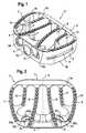
- Fig. 1shows in a perspective exploded view a first embodiment of a fixation device according to the present invention, which in this instance is a intervertebral implant device 100.
- Fig. 2shows a plan view thereof.
- the device 100comprises a device body 1, which has the form of a cage.
- the cageis made of a biocompatible material such as titanium, a titanium alloy or PEEK (polyetheretherketones) and is provided with a substantially vertical sidewall enclosing one or more inner hollow spaces. The spaces are open toward an upper and a lower face 3a, 3b of the cage 1.
- the sidewall of the cage 1is composed of a front wall 4, a back wall 5, a right side wall 6 and a left side wall 7, which are integrally formed, such that the right and left side wall connect the front and back walls with each other.
- the front wall 4represents an anterior wall and the back wall 5 represents a posterior wall of the cage 1.
- the rigidity of the cage 1is further stabilized by two inner walls 8, 9 which extend in arc-shape from the back wall 5 towards the front wall 4. Both inner walls are symmetric with respect to the sagittal plane S.
- each of the walls 8 to 11has an arc-shape that is concave towards the sagittal plane, whereas the left and right side walls 6, 7 are convex thereto. This arrangement of side walls and inner walls has been found to provide an optimum load transfer at the cage-bone interface.
- the five spaces defined by the side walls and inner wallsare designed to be filled with bone graft material.
- small teeth 16are provided on the upper and lower edges of each of the walls, i.e., on the upper and lower faces of the cage 1, in order to facilitate a carve-in of both faces into the end plates of the adjacent vertebral bodies 40, 42.
- the shape of the series of small teethdirectly corresponds to the shape of the walls and is further optimized to anatomically fit to the adjacent vertebral bodies, i.e., good distribution of stress and torsion stability.
- the cage 1is also provided with three bores 2a, 2b, 2c each for receiving or accommodating a bone screw.
- the bores 2a-care located on the front wall 4 of the cage 1, wherein one center bore 2b is inclined downward and two side bores 2a, 2c are inclined upwards.
- the reverse casemay be arranged as well, i.e., the center bore 2b is inclined upwards and the two side bores 2a, 2c are inclined downwards.
- the bores 2a, 2chave each an opening 18a, 18c respectively towards the upper face 3a of the cage 1. Due to the specific shape and arrangement of the inner walls 8 to 11, each of the three bores also opens (under respective inclinations with regard to the transversal plane) toward its own distinct inner space confined by these walls 8 to 11.
- the openings 22a and 22c of the boresare provided in respective end faces 20a, 20c which form part of inclined inner surfaces of the front wall 4 towards the inner spaces of the cage 1.
- the end faces 20a, 20care oriented substantially perpendicular to respective longitudinal axes of the bores 2a-c. As will be detailed below, the end faces form an abutment area for projecting parts of thread runouts towards a clearance groove formed on the bone screws 30a to 30c.
- Figs. 3A and 3Billustrate the insertion of the cage 1 between two adjacent vertebral bodies 40, 42.
- a holding slot 14is provided on either side of the cage 1, i.e., within the right side wall 6 and the left side wall 7.
- the holding slot 14is elongated and extends in the transversal plane T of the cage 1.
- the slotallows engagement by a holding instrument which facilitates insertion of the cage 1.
- the cage 1represents an anterior lumbar interbody fusion cage (ALIF-cage), wherein the cage is to be introduced between two adjacent vertebrae of the lumbar spinal column from the anterior direction in order to replace a spinal disc, for example.
- ALIF-cageanterior lumbar interbody fusion cage
- bone screws 30a-care inserted in respective bores 2a-c and screwed into end plates of the vertebral bodies 40, 42 ( Fig. 3B ).
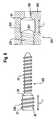
- a simplified construction of the bores 2' and the corresponding bone screws 30'is shown in the embodiment of Fig. 4 .
- Like numeralsdenote the same or similar components in the figures.
- the bone screw 30'is composed of substantially three sections: a head section 36, a first (threaded) shaft section which defines a bone thread, and a second shaft section including a clearance groove 34a.
- the first shaft sectionhas an external bone thread 32 which is designed to be drilled and cut into the bone material of the adjacent end plates of the vertebral bodies 40, 42.
- the bone threadis formed by helical grooves 39 and helical projections 38.
- the second shaft sectionhas a clearance groove 34a that extends from a thread runout portion of the external thread towards the head section 36.
- the second shaft portionhas a diameter, which in this embodiment is substantially the same as a core diameter 31 of the threaded portion 32, i.e., a diameter as measured with regard to the helical grooves of the external thread.
- the diameter of the clearance groove 34ais smaller than that of the helical projections 38 which form the thread 32 (outer diameter).
- the bone screwis first inserted into the bore 2' formed in front wall 4 which has the internal thread portion 22 and a cylindrical guiding portion 52.
- the cylindrical guiding portion 52is arranged to accommodate the head section 36 of the bone screw, wherein respective diameters are substantially the same in order to provide suitable guideance.
- the diameter of the guiding portion 52is larger than that of the internal thread portion 22, wherein a transition between both portions is represented by a conical stop 50, which may be engaged by a corresponding conical catch 35 formed on the head section 36 of the bone screw 30' when a state of compression is reached (bottom portion of Fig. 4 ).
- the external bone thread 32 of the bone screw and the internal thread 22 of the boreare adapted to engage with each other.
- the bone screwmay be screwed through the internal thread 22 (middle portion of Fig. 4 ).
- a longitudinal length of the clearance groove 34is substantially the same as that of the internal thread 22. More precisely, this length of the clearance groove is substantially the same as the distance between the stop 50 and the opening 18' towards the end face 20' of the front wall 4 of the cage 1. As a consequence, the thread portions 22, 32 disengage when the catch 35 abuts on the stop 50.
- Fig. 5shows in a similarly simplified construction an alternative embodiment of the present invention. Same numerals denote the same or like components.
- the head section 36 of the bone screw 30"is considerably shortened as compared with the previous second embodiment.
- the resulting deficiency in stably guiding the bone screw upon insertionis compensated by the feature of the clearance groove 34b, which in this embodiment has an increased thickness as compared with the core diameter 31 of the thread portion 32.
- the diameter of the clearance groove 34bis in fact smaller than the outer diameter due to the helical projection of the thread portion 32, such that the clearance groove may pass the internal thread portion of the bore 2''.
- the clearance groove 34bis in close contact to corresponding projections (not shown in detail) of the internal thread portion of the bore in order to carry out the tight guiding function for the bone screw.
- the internal thread portion 22simultaneously serves as the guiding portion 52b.
- Numeral 52a(upper portion of Fig. 5 ) merely denotes a seat for the shortened head section 36.
- Fig. 6shows the corresponding construction of the bone screw mechanism with regard to the first embodiment illustrated in Figs. 1 to 3 .
- the same numeralsdenote the same or like components as in the other embodiments. Shown are the steps of inserting (59) the bone screw, screwing (60) the bone screw 30a-c through the internal thread portion of the bores 2a-c and further rotating (61) the bone screw to lock the same as detailed above with respect to Fig. 4 . Also illustrated are the resulting forces F 1 , F 2 acting on the head section 36 via catch 35 and the first shaft section of the bone screw 30a-c via the external thread portion (bottom potion of Fig. 6 ).
- Figs. 7A, 7B , 8A and 8Billustrate the operation of locking or securing the intervertebral implant device 100 according to the first embodiment.
- a hexagon head bone screwis employed and a hexagon wrench key is applied to screw the bone screw 30c shown Figs. 7A and 8A .
- Fig. 7Ashows a state in which the catch 35 abuts on the stop 50 and the clearance groove 34c extends throughout the internal thread portion 22c of the bore 2c within front wall 4. Hence, compression starts upon further screwing.
- Fig. 9shows an alternative embodiment.
- the same reference numeralsdenote the same or similar parts and components as shown in the previous embodiments.
- One differenceis that the bone screw lacks a clearance groove.
- a protection or securing mechanism against fall-out of the screwis achieved by providing a second thread portion 330 to the bone screw 300, more specifically to the head section 36 thereof.
- the bore 200 formed in the front wall 400 of the cage(or a plate 400 of a plate assembly, when a bone fixation plate is considered) comprises the first internal thread portion 220 and a cylindrical guiding portion 520 adjacent to the internal thread portion.
- the second external thread portion 330 of the bone screw 300cooperates with the internal thread portion of the head, while the first thread portion (bone thread) 32 merely cooperates with the bone material of the adjacent bones.
- the narrow opening 180 for receiving the shaft section of the bone screwis not provided with a thread.
- the securing mechanismis as follows: after inserting the bone screw into the bore 200 of the front wall 400 of the cage, or the plate, the second thread potion (head thread) 330 is screwed through the internal thread 220 of the bore 200.
- the thread length L1 of the head threadis the same as the length of the cylindrical guiding portion 520, the external thread 330 leaves or disengages from the internal thread 220 just when the catch 35 abuts on the stop 50.
- the bone screwDue to the cylindrical symmetry of the guiding portion 520, the bone screw is now freely rotatable within the bore. Hence, further compression of the catch against the stop is achieved, when the bone thread is further screwed into the adjacent bone material more deeply by for example 80 or 90 degrees to 270 or 280 degrees.
- the helical projection 37 at the thread runout of the head thread 330is thereby misoriented relative to the thread inlet of the internal thread 220 within the bore 200. Consequently, the projection 37 abuts on a corresponding end face 201 within the bore at a transition between internal thread 220 and the cylindrical guiding portion 520.
- the screwcannot not easily fall out of the cage or plate even if it is loosened in the bone material. Rather, the head section will securely be kept within the cylindrical guiding portion 520.
- the bone screwmay be screwed into the bone material by mechanisms and tools than hexagon head screws, which are well known in the art.
- the materials employed for the cage and the screwmay be chosen according to the specific needs.
- the embodiments employing three bores for accommodating three bone screwshave been found and described as providing an optimized design with regard to stress and torsion distribution, other designs employing two, four or more bore and bone screws can be employed as well.
- the inventionis not limited to the specific arrangement of inner and outer side walls of the cage as shown in the present embodiments. In particular, the invention encompasses applications regarding bone plates or similar bone fixation devices.
Landscapes
- Health & Medical Sciences (AREA)
- Orthopedic Medicine & Surgery (AREA)
- Engineering & Computer Science (AREA)
- Biomedical Technology (AREA)
- Neurology (AREA)
- Life Sciences & Earth Sciences (AREA)
- Surgery (AREA)
- General Health & Medical Sciences (AREA)
- Veterinary Medicine (AREA)
- Heart & Thoracic Surgery (AREA)
- Public Health (AREA)
- Animal Behavior & Ethology (AREA)
- Molecular Biology (AREA)
- Medical Informatics (AREA)
- Nuclear Medicine, Radiotherapy & Molecular Imaging (AREA)
- Cardiology (AREA)
- Oral & Maxillofacial Surgery (AREA)
- Transplantation (AREA)
- Vascular Medicine (AREA)
- Prostheses (AREA)
- Surgical Instruments (AREA)
Description
- The invention relates to a fixation device used to provide a rigid or flexible connection between bones of the human body. The invention particularly relates to an intervertebral implant device, comprising a device body having an upper face and a lower face for engaging with an end plate of an upper and a lower vertebral body, respectively, a side wall and at least one bore, which is formed in the side wall for receiving a bone screw as a fixation element to be inserted into vertebral body.
- The bone screw typically has a shaft section with an external thread portion arranged to be anchored in the adjacent vertical body, and a head section which has a diameter larger than that of the shaft section to provide a catch arranged to engage with a stop formed in the bore of the device body.
- Document
US 2006/0085071 A1 discloses an intervertebral implant device including a body with an upper side, an under side and a front surface, in which four bore holes suited to accommodate respective bone screws are formed. The body may be formed of body-compatible plastic material. To provide rigidity and strength to the device, a small front plate made from a metallic material such as titanium or titanium alloy is attached to the front surface. Four bore holes corresponding in position to the respective bore holes of the plastic body are formed in the front plate. The bone screws may each be inserted through the bore holes of the front plate and then also extend through the bore holes of the plastic body. - The bore holes of the front plate are provided with internal threads. These internal threads correspond to external threads provided on the respective heads of the bone screws. In order to enable fixation and compression, the threaded heads are conically shaped, thereby tapering towards the shaft sections of the bone screws.
- With regard to such a construction, a problem may arise that the screws may loosen and by application of external forces exerted on the vertebral bodies may slowly be screwed out, which may result in severe damages of, e.g., adjacent blood vessels, and loosening of the whole implant. For this reason,
US 2006/0085071 A1 further proposes to attach a securing plate to the front plate. The securing plate covers respective openings of the bore holes in the front plate and thus secures the bone screws inserted therein. As a consequence, the bone screws cannot be screwed out or fall out. - The number of parts used to implement the above described intervertebral implant device is increased and the dimensions of the device may become disadvantageously large. Further, an additional screwing step has to be applied by the surgery in order to secure the bone screws against falling out.
Document EP 1 280 481 A1 shows an intersomatic implant device comprising a cage which is composed of a sidewall. However, the holes or bores provided in the sidewall of the cage are not shown to accommodate bone screws to be inserted therein.- Document
WO 01/56513 A1 - Document
US 6,558,423 B1 shows an intervertebral implant having side walls and bone screw receiving holes. The corresponding bone screw has a shaft section including a bone thread and a head portion which comprises a threaded portion and an enlarged portion. The width of the enlarged portion extends beyond that of the threaded head portion such that it may abut on an outer surface of the side wall. - Document
WO 2004/064655 A1 discloses a medical implant comprising a secured bone screw. The bone screw comprises a head, a thread and a non-threaded section between the head and the thread. The implant comprises a flange which has bore holes. The flange is to be attached to an endo-prosthesis by means of the bone screws. A turn-hindering device prevents the screw from coming out from the endo-prosthesis. - It is thus an object to provide an improved intervertebral implant device, which simplifies handling of inserting the device between two vertebral bodies, which increases its stability against external forces once the device has been installed, which provides an efficient downsizing of the components used and/or which protects the bone screws against being screwed out or falling out in case these are loosened.
- The object is solved by a fixation device comprising the combination of features according to appended
claim 1. Advantageous aspects and embodiments are evident from the dependent claims. - The present fixation device is arranged to provide a mechanism, which may hold a bone screw as a fixation element in place, which is to be inserted into an adjacent bone such as a vertebral body, even if it is loosened. For this purpose, the shaft of the bone screw has two sections: one section that is provided with the external thread portion and another section that is provided with a clearance groove.
- The external thread portion may engage with the internal thread portion of a bore provided in the device body. The shaft section which includes the clearance portion extends between a head section of the bone screw and the shaft section including the external thread portion.
- Hence, the bone screw may first be screwed into the internal thread portion of the bore using its external thread portion. Then upon further screwing-in of the bone screw, owing to the clearance groove, the external thread portion disengages from the internal thread portion once the entire length in longitudinal direction of the internal thread in the bore of the device body is opposed by the clearance groove.
- However, it becomes further possible to continue rotation of the fixation element by, e.g., an angle of about 90 to about 270 degrees in order to separate the orientation of the thread runout of the external thread of the bone screw with respect to the thread inlet of the internal thread portion of the bore. Thus, even if the bone screw fixed in the bone, e.g., the vertebral body, is loosened with time, the helical projection part of external thread at the position of the thread runout abuts with an end face surrounding the opening of the bore due to this misorientation by, e.g., 90-270 degrees. As a result, the device body urges the bone screw to be held in place within the bone, or vertebral body respectively, in this instance.
- According to an alternative but similar aspect of the invention, the bone screw is provided with a second external thread portion at the head section. This second thread portion cooperates with the internal thread portion, while the first external thread portion, i.e., the bone thread, cooperates with the bone material. A cylindrical guiding portion is formed within the bore adjacent to the internal thread portion in order to receive the head section when the second thread disengages from the internal thread portion in the bore.
- The principles of abutment of the helical projection at the thread runout of second thread are the same as in the first aspect. I.e., after disengaging from the second external thread portion, the projection abuts on a respective end face inside the bore in case of a misorientation of the thread runout by for example 90 - 270 degrees with regard to the thread inlet of the internal thread portion. Hence, the same degree of protection against fall-out of the bone screw may be achieved as in the first aspect.
- It is noted that the fixation device as proposed herein comprises a member, which is to be fixed to one or more adjacent bones, and the bone screw as the fixation element. In one embodiment this member may be embodied as a cage employed for connecting adjacent vertebral bodies.
- However, the device is not limited to applications regarding the replacement of intervertebral discs by means of such cages. Rather, according to other embodiments the member may have plate-like, sleeve-like or any other suitable shapes depending on the application, in order to fix or stabilize bones of the spinal column and other areas of the remainder skeleton.
- A few other fixation devices are provided comprising plates for fixing the cervical spine or plates for laterally fixing the thoracolumbar vertebrae using bone screws. All other types of plate assemblies are embodied as well.
- Further features and advantages of the present fixation device will become apparent and will be best understood by reference of the following detailed description taken in conjunction with the accompanying drawings.
- Fig. 1
- shows a perspective exploded view of an intervertebral implant device according to a first embodiment;
- Fig. 2
- shows a plan view of the device according to
Fig. 1 ; - Fig. 3
- shows a schematical illustration of an insertion process for the device according to
Fig. 1 between two vertebral bodies; - Fig. 4
- shows in a schematical representation in three sectional views steps of inserting a fixation element having a clearance groove into a device body according to a second embodiment;
- Fig. 5
- same as
Fig. 4 , but with a clearance groove increased in diameter according to a third embodiment; - Fig. 6
- same as
Fig. 4 , but with regard to the embodiment shown inFigs. 1-3 ; - Fig. 7A
- shows a partially enlarged perspective exploded view of the fixation element being inserted into the bore according to the first embodiment, wherein a state of compression prior to locking is achieved;
- Fig. 7B
- shows a schematical view of the relative orientations of the thread runout of the external thread of the fixation element and the thread inlet of the internal thread of the bore of the device body as present in the state shown in
Fig. 7A ; - Fig. 8A
- same as
Fig. 7A , but in a state after locking, i.e. further rotation by 90-270 degrees; - Fig. 8B
- same as
Fig. 7B , but with a corresponding misorientation of the thread runout verus the thread inlet resulting from the locking rotation shown in the state ofFig. 8A ; - Fig. 9
- shows a schematical illustration of an alternative embodiment of the invention.
Fig. 1 shows in a perspective exploded view a first embodiment of a fixation device according to the present invention, which in this instance is aintervertebral implant device 100.Fig. 2 shows a plan view thereof. Thedevice 100 comprises adevice body 1, which has the form of a cage. The cage is made of a biocompatible material such as titanium, a titanium alloy or PEEK (polyetheretherketones) and is provided with a substantially vertical sidewall enclosing one or more inner hollow spaces. The spaces are open toward an upper and alower face cage 1.- The sidewall of the
cage 1 is composed of afront wall 4, aback wall 5, aright side wall 6 and a left side wall 7, which are integrally formed, such that the right and left side wall connect the front and back walls with each other. Thefront wall 4 represents an anterior wall and theback wall 5 represents a posterior wall of thecage 1. - The rigidity of the
cage 1 is further stabilized by twoinner walls back wall 5 towards thefront wall 4. Both inner walls are symmetric with respect to the sagittal plane S. - There are two further
inner walls side walls 6, 7, respectively. Similar toinner walls walls walls 8 to 11 has an arc-shape that is concave towards the sagittal plane, whereas the left andright side walls 6, 7 are convex thereto. This arrangement of side walls and inner walls has been found to provide an optimum load transfer at the cage-bone interface. - The five spaces defined by the side walls and inner walls are designed to be filled with bone graft material. Further,
small teeth 16 are provided on the upper and lower edges of each of the walls, i.e., on the upper and lower faces of thecage 1, in order to facilitate a carve-in of both faces into the end plates of the adjacentvertebral bodies - The
cage 1 is also provided with threebores bores 2a-c are located on thefront wall 4 of thecage 1, wherein onecenter bore 2b is inclined downward and twoside bores side bores Fig. 2 , thebores opening upper face 3a of thecage 1. Due to the specific shape and arrangement of theinner walls 8 to 11, each of the three bores also opens (under respective inclinations with regard to the transversal plane) toward its own distinct inner space confined by thesewalls 8 to 11. - For the present application to cages intended to replace intervertebral disks, inclination angles of 45 ° ± 20 ° may typically be arranged. In case of applications to fixation plates inclination angles of about 90 ° ± 30 ° will typically be employed. However, the invention shall not be limited to the specific values or ranges indicated above.
- The
openings front wall 4 towards the inner spaces of thecage 1. The end faces 20a, 20c are oriented substantially perpendicular to respective longitudinal axes of thebores 2a-c. As will be detailed below, the end faces form an abutment area for projecting parts of thread runouts towards a clearance groove formed on the bone screws 30a to 30c. Figs. 3A and 3B illustrate the insertion of thecage 1 between two adjacentvertebral bodies slot 14 is provided on either side of thecage 1, i.e., within theright side wall 6 and the left side wall 7. The holdingslot 14 is elongated and extends in the transversal plane T of thecage 1. The slot allows engagement by a holding instrument which facilitates insertion of thecage 1. In this embodiment thecage 1 represents an anterior lumbar interbody fusion cage (ALIF-cage), wherein the cage is to be introduced between two adjacent vertebrae of the lumbar spinal column from the anterior direction in order to replace a spinal disc, for example.- Once the
cage 1 is appropriately positioned between thevertebral bodies respective bores 2a-c and screwed into end plates of thevertebral bodies 40, 42 (Fig. 3B ). For explanation purposes, a simplified construction of thebores 2' and the corresponding bone screws 30' is shown in the embodiment ofFig. 4 . Like numerals denote the same or similar components in the figures. - The bone screw 30' according to this embodiment (see upper portion of
Fig. 4 first) is composed of substantially three sections: ahead section 36, a first (threaded) shaft section which defines a bone thread, and a second shaft section including aclearance groove 34a. The first shaft section has anexternal bone thread 32 which is designed to be drilled and cut into the bone material of the adjacent end plates of thevertebral bodies helical grooves 39 andhelical projections 38. - The second shaft section has a
clearance groove 34a that extends from a thread runout portion of the external thread towards thehead section 36. The second shaft portion has a diameter, which in this embodiment is substantially the same as acore diameter 31 of the threadedportion 32, i.e., a diameter as measured with regard to the helical grooves of the external thread. In other words, the diameter of theclearance groove 34a is smaller than that of thehelical projections 38 which form the thread 32 (outer diameter). - The bone screw is first inserted into the
bore 2' formed infront wall 4 which has theinternal thread portion 22 and a cylindrical guidingportion 52. Thecylindrical guiding portion 52 is arranged to accommodate thehead section 36 of the bone screw, wherein respective diameters are substantially the same in order to provide suitable guideance. Moreover, the diameter of the guidingportion 52 is larger than that of theinternal thread portion 22, wherein a transition between both portions is represented by aconical stop 50, which may be engaged by a correspondingconical catch 35 formed on thehead section 36 of the bone screw 30' when a state of compression is reached (bottom portion ofFig. 4 ). - The
external bone thread 32 of the bone screw and theinternal thread 22 of the bore are adapted to engage with each other. Hence, the bone screw may be screwed through the internal thread 22 (middle portion ofFig. 4 ). A longitudinal length of the clearance groove 34 is substantially the same as that of theinternal thread 22. More precisely, this length of the clearance groove is substantially the same as the distance between thestop 50 and the opening 18' towards the end face 20' of thefront wall 4 of thecage 1. As a consequence, thethread portions catch 35 abuts on thestop 50. - Further screwing leads to a compression of the
cage 1 against the end plate of thevertebral body helical projection 37 at the thread runout with respect to the thread inlet 54 (i.e., the groove of the internal thread which enters the opening 18') of theinternal thread 22. Thus, thehelical projection 37 of theexternal thread 32 at the thread runout abuts on the end face 20' upon further screwing (rotation of the bone screw 30'). Fig. 5 shows in a similarly simplified construction an alternative embodiment of the present invention. Same numerals denote the same or like components. In this embodiment, thehead section 36 of thebone screw 30" is considerably shortened as compared with the previous second embodiment. The resulting deficiency in stably guiding the bone screw upon insertion is compensated by the feature of theclearance groove 34b, which in this embodiment has an increased thickness as compared with thecore diameter 31 of thethread portion 32.- However, the diameter of the
clearance groove 34b is in fact smaller than the outer diameter due to the helical projection of thethread portion 32, such that the clearance groove may pass the internal thread portion of thebore 2''. Thereby, theclearance groove 34b is in close contact to corresponding projections (not shown in detail) of the internal thread portion of the bore in order to carry out the tight guiding function for the bone screw. In other words, theinternal thread portion 22 simultaneously serves as the guidingportion 52b. Numeral 52a (upper portion ofFig. 5 ) merely denotes a seat for the shortenedhead section 36. Fig. 6 shows the corresponding construction of the bone screw mechanism with regard to the first embodiment illustrated inFigs. 1 to 3 . The same numerals denote the same or like components as in the other embodiments. Shown are the steps of inserting (59) the bone screw, screwing (60) thebone screw 30a-c through the internal thread portion of thebores 2a-c and further rotating (61) the bone screw to lock the same as detailed above with respect toFig. 4 . Also illustrated are the resulting forces F1, F2 acting on thehead section 36 viacatch 35 and the first shaft section of thebone screw 30a-c via the external thread portion (bottom potion ofFig. 6 ).Figs. 7A, 7B ,8A and 8B illustrate the operation of locking or securing theintervertebral implant device 100 according to the first embodiment. In this specific embodiment a hexagon head bone screw is employed and a hexagon wrench key is applied to screw thebone screw 30c shownFigs. 7A and8A .Fig. 7A shows a state in which thecatch 35 abuts on thestop 50 and theclearance groove 34c extends throughout theinternal thread portion 22c of thebore 2c withinfront wall 4. Hence, compression starts upon further screwing.- Simultaneously with further compression,
further rotation 61 of thescrew 30c by, e.g., 85 degrees misorients thehelical projection 37 at the thread runout of theexternal thread portion 32 with respect to the thread inlet 54 (not visible inFigs. 7 and8 due to the sectional view) in theopening 22c ofbore 2c. The orientation is shown in the schematical sketches ofFigs. 7B and8B . Upon loosening of the bone screw, any force acting on thebone scew 30c to screw it out would result in an increasing abutment of theprojection 37 on theend face 20c of the front wall as long as the thread runout fails to meet thethread inlet 54 of thebore 2c. Hence, a securing function is achieved with the present embodiment. Fig. 9 shows an alternative embodiment. The same reference numerals denote the same or similar parts and components as shown in the previous embodiments. One difference is that the bone screw lacks a clearance groove. However, a protection or securing mechanism against fall-out of the screw is achieved by providing asecond thread portion 330 to thebone screw 300, more specifically to thehead section 36 thereof.- The
bore 200 formed in thefront wall 400 of the cage (or aplate 400 of a plate assembly, when a bone fixation plate is considered) comprises the firstinternal thread portion 220 and acylindrical guiding portion 520 adjacent to the internal thread portion. In this embodiment, the secondexternal thread portion 330 of thebone screw 300 cooperates with the internal thread portion of the head, while the first thread portion (bone thread) 32 merely cooperates with the bone material of the adjacent bones. - For this reason, the
narrow opening 180 for receiving the shaft section of the bone screw is not provided with a thread. - The securing mechanism is as follows: after inserting the bone screw into the
bore 200 of thefront wall 400 of the cage, or the plate, the second thread potion (head thread) 330 is screwed through theinternal thread 220 of thebore 200. AS the thread length L1 of the head thread is the same as the length of thecylindrical guiding portion 520, theexternal thread 330 leaves or disengages from theinternal thread 220 just when thecatch 35 abuts on thestop 50. - Due to the cylindrical symmetry of the guiding
portion 520, the bone screw is now freely rotatable within the bore. Hence, further compression of the catch against the stop is achieved, when the bone thread is further screwed into the adjacent bone material more deeply by for example 80 or 90 degrees to 270 or 280 degrees. Thehelical projection 37 at the thread runout of thehead thread 330 is thereby misoriented relative to the thread inlet of theinternal thread 220 within thebore 200. Consequently, theprojection 37 abuts on acorresponding end face 201 within the bore at a transition betweeninternal thread 220 and thecylindrical guiding portion 520. - As a result, the screw cannot not easily fall out of the cage or plate even if it is loosened in the bone material. Rather, the head section will securely be kept within the
cylindrical guiding portion 520. - It is to be understood that the present invention shall not be limited by detailed features as explained herein. Rather, it is within the scope of the invention to apply various modifications to the embodiments described above. For example, the bone screw may be screwed into the bone material by mechanisms and tools than hexagon head screws, which are well known in the art. Also, as an example, the materials employed for the cage and the screw may be chosen according to the specific needs.
- Still further, although the embodiments employing three bores for accommodating three bone screws have been found and described as providing an optimized design with regard to stress and torsion distribution, other designs employing two, four or more bore and bone screws can be employed as well. Also, the invention is not limited to the specific arrangement of inner and outer side walls of the cage as shown in the present embodiments. In particular, the invention encompasses applications regarding bone plates or similar bone fixation devices.
Claims (13)
- A fixation device (100) for bones (40, 42), comprising:a member (1) which is to be fixed to one or more bones and has at least three bores (2a-c, 2', 2") for receiving each a bone screw (30), wherein the at least three bores comprises a first internal thread portion (22a-c, 22);the bone screw (30) for insertion through a respective one of the bores (2) into the bone, the bone screw having:a first shaft section provided with a first external thread portion (32) arranged to cooperate with the internal thread portion (22a-c, 22) of at least the one bore;a head section (36) having a diameter larger than that of the shaft section to provide a catch (35) arranged to engage with a stop (50) formed in the bore;a second shaft section which comprises a clearance groove (34a-c) extending between the catch (35) of the head section and the external thread (32) of the first shaft section;wherein the fixation device is arranged as an intervertebral implant device, wherein the member (1) comprises:a device body havingan upper face (3a) and a lower face (3b) for engaging with an end plate of an upper (40) and a lower vertebral body (42), respectively, andan outer side wall including a back wall (5) and a front wall (4) in which at least three bores are formed, and two inner walls (8, 9) for stabilizing the rigidity of the fixation device, wherein the two inner walls (8, 9) extend from the back wall (5) to the front wall (4) connecting the same,wherein each of the at least three bores opens into its own distinct and separate inner space confined by the inner walls (8, 9), respectively.
- The fixation device according to claim 1, wherein:the second shaft section of the bone screw (30) has an outer diameter smaller than the inner diameter of the first internal thread portion of the bore.
- The fixation device according to one of claims 1 to 2, wherein:the second shaft section defined by the clearance groove (34a) has a length substantially equal to a length of the first internal thread portion (22a-c, 22) of the bore.
- The fixation device according to one of claims 1 to 3, wherein:the external thread portion (32) of the first shaft portion comprises a helical projection (38);a thread runout is provided at a transition between the external thread (32) of the first shaft section and the clearance groove (34a) of the second shaft section;the helical projection (38) provided at the thread runout is arranged to abut on an end face (20a-c, 20') of the device body surrounding an opening (18a-c, 18, 18') of the bore, when the catch (35) of the head section (36) abuts on the stop (50) formed within the bore.
- The fixation device according to one of claims 1 to 4, wherein:the second shaft section defined by the clearance groove (34a) has an outer diameter smaller than an outer diameter of the first shaft section.
- The fixation device according to claim 5, wherein:the clearance groove (34a) of the second shaft section has an outer diameter equal to or larger than a diameter of a core portion of the first shaft section.
- The fixation device according to one of claims 1 to 6, wherein:the clearance groove (34a) of the second shaft section is non-threaded and has a substantially cylindrical shape.
- The fixation device according to one of claims 1 to 7, wherein:the bore (2a-c, 2', 2") further has a cylindrical guiding portion (52) which extends adjacent to the stop and has a diameter larger than that of the internal thread portion (22a-c, 22') of the bore in order to receive the head section (36) of the bone screw.
- The fixation device according to claim 1, wherein:the front wall (4) is further connected to a back wall (5) via the two first arc-shaped vertical inner walls (8, 9).
- The fixation device according to claim 9, wherein:a left side wall (6) and a right side wall (7) forming part of the sidewall are each connected with the back wall (5) via two second arc-shaped inner walls (10, 11).
- The fixation device according to claim 10, wherein:each one of the three bores opens toward a separate inner space of the device body, the inner spaces being open towards the end plates of the adjacent vertebral bodies and referring to one of:(a) a space between the two first arc-shaped inner walls (8, 9);(b) a space between one (8) of the two first arc-shaped inner walls and a left one (10) of two second arc-shaped inner walls;(c) a space between the other (9) of the two first arc-shaped inner walls and a right one (11) of two second arc-shaped inner walls.
- The fixation device according to one of claims 1 to 11, wherein:the upper (3 a) and lower faces (3c) of the device body are provided with small teeth (16) to be buried into the end plates of the adjacent vertebral bodies (40, 42) upon compression due to the bone screw(s).
- The fixation device according to one of claims 1 to 12, which is arranged as an anterior lumbar interbody fusion (ALIF) device.
Priority Applications (12)
| Application Number | Priority Date | Filing Date | Title |
|---|---|---|---|
| ES11156966TES2404883T3 (en) | 2007-07-26 | 2007-07-26 | Bone fixation device |
| EP07014710AEP2018827B1 (en) | 2007-07-26 | 2007-07-26 | Fixation device for bones |
| ES07014710TES2387506T3 (en) | 2007-07-26 | 2007-07-26 | Bone fixation device |
| EP11156966AEP2340776B1 (en) | 2007-07-26 | 2007-07-26 | Fixation device for bones |
| TW097127720ATWI428117B (en) | 2007-07-26 | 2008-07-22 | Fixation device for bones |
| JP2008189839AJP5221232B2 (en) | 2007-07-26 | 2008-07-23 | Fixation device for bone and method of implanting intervertebral implant device |
| KR1020080071704AKR101559861B1 (en) | 2007-07-26 | 2008-07-23 | Fixation Device for Bones |
| CN201410112153.5ACN103860248B (en) | 2007-07-26 | 2008-07-23 | Bone anchoring device |
| CN200810134158.2ACN101352367B (en) | 2007-07-26 | 2008-07-23 | bone fixation device |
| US12/180,462US8790405B2 (en) | 2007-07-26 | 2008-07-25 | Fixation device for bones |
| US13/613,584US8834570B2 (en) | 2007-07-26 | 2012-09-13 | Fixation device for bones |
| JP2013044313AJP5485435B2 (en) | 2007-07-26 | 2013-03-06 | Fixation device for bone and method of implanting intervertebral implant device |
Applications Claiming Priority (1)
| Application Number | Priority Date | Filing Date | Title |
|---|---|---|---|
| EP07014710AEP2018827B1 (en) | 2007-07-26 | 2007-07-26 | Fixation device for bones |
Related Child Applications (1)
| Application Number | Title | Priority Date | Filing Date |
|---|---|---|---|
| EP11156966.1Division-Into | 2011-03-04 |
Publications (2)
| Publication Number | Publication Date |
|---|---|
| EP2018827A1 EP2018827A1 (en) | 2009-01-28 |
| EP2018827B1true EP2018827B1 (en) | 2012-05-02 |
Family
ID=39057027
Family Applications (2)
| Application Number | Title | Priority Date | Filing Date |
|---|---|---|---|
| EP07014710AActiveEP2018827B1 (en) | 2007-07-26 | 2007-07-26 | Fixation device for bones |
| EP11156966AActiveEP2340776B1 (en) | 2007-07-26 | 2007-07-26 | Fixation device for bones |
Family Applications After (1)
| Application Number | Title | Priority Date | Filing Date |
|---|---|---|---|
| EP11156966AActiveEP2340776B1 (en) | 2007-07-26 | 2007-07-26 | Fixation device for bones |
Country Status (7)
| Country | Link |
|---|---|
| US (2) | US8790405B2 (en) |
| EP (2) | EP2018827B1 (en) |
| JP (2) | JP5221232B2 (en) |
| KR (1) | KR101559861B1 (en) |
| CN (2) | CN103860248B (en) |
| ES (2) | ES2404883T3 (en) |
| TW (1) | TWI428117B (en) |
Cited By (4)
| Publication number | Priority date | Publication date | Assignee | Title |
|---|---|---|---|---|
| US9216096B2 (en) | 2010-03-16 | 2015-12-22 | Pinnacle Spine Group, Llc | Intervertebral implants and related tools |
| US9380932B1 (en) | 2011-11-02 | 2016-07-05 | Pinnacle Spine Group, Llc | Retractor devices for minimally invasive access to the spine |
| US10070970B2 (en) | 2013-03-14 | 2018-09-11 | Pinnacle Spine Group, Llc | Interbody implants and graft delivery systems |
| WO2024108277A1 (en)* | 2022-11-21 | 2024-05-30 | Filho Osvaldo Piovezani | Limiting screw for preventing the migration of a lumbar prosthesis |
Families Citing this family (104)
| Publication number | Priority date | Publication date | Assignee | Title |
|---|---|---|---|---|
| US6206922B1 (en)* | 1995-03-27 | 2001-03-27 | Sdgi Holdings, Inc. | Methods and instruments for interbody fusion |
| FR2897259B1 (en) | 2006-02-15 | 2008-05-09 | Ldr Medical Soc Par Actions Si | INTERSOMATIC TRANSFORAMINAL CAGE WITH INTERBREBAL FUSION GRAFT AND CAGE IMPLANTATION INSTRUMENT |
| FR2824261B1 (en) | 2001-05-04 | 2004-05-28 | Ldr Medical | INTERVERTEBRAL DISC PROSTHESIS AND IMPLEMENTATION METHOD AND TOOLS |
| FR2827156B1 (en) | 2001-07-13 | 2003-11-14 | Ldr Medical | VERTEBRAL CAGE DEVICE WITH MODULAR FASTENING |
| FR2846550B1 (en) | 2002-11-05 | 2006-01-13 | Ldr Medical | INTERVERTEBRAL DISC PROSTHESIS |
| FR2865629B1 (en)* | 2004-02-04 | 2007-01-26 | Ldr Medical | INTERVERTEBRAL DISC PROSTHESIS |
| EP2113227B1 (en) | 2004-02-04 | 2015-07-29 | LDR Medical | Intervertebral disc prosthesis |
| FR2869528B1 (en) | 2004-04-28 | 2007-02-02 | Ldr Medical | INTERVERTEBRAL DISC PROSTHESIS |
| WO2006058221A2 (en) | 2004-11-24 | 2006-06-01 | Abdou Samy M | Devices and methods for inter-vertebral orthopedic device placement |
| FR2879436B1 (en) | 2004-12-22 | 2007-03-09 | Ldr Medical | INTERVERTEBRAL DISC PROSTHESIS |
| US9848993B2 (en) | 2005-04-12 | 2017-12-26 | Nathan C. Moskowitz | Zero-profile expandable intervertebral spacer devices for distraction and spinal fusion and a universal tool for their placement and expansion |
| US9814601B2 (en) | 2005-04-12 | 2017-11-14 | Nathan C. Moskowitz | Bi-directional fixating/locking transvertebral body screw/intervertebral cage stand-alone constructs |
| US7942903B2 (en) | 2005-04-12 | 2011-05-17 | Moskowitz Ahmnon D | Bi-directional fixating transvertebral body screws and posterior cervical and lumbar interarticulating joint calibrated stapling devices for spinal fusion |
| US11903849B2 (en)* | 2005-04-12 | 2024-02-20 | Moskowitz Family Llc | Intervertebral implant and tool assembly |
| US7972363B2 (en) | 2005-04-12 | 2011-07-05 | Moskowitz Ahmnon D | Bi-directional fixating/locking transvertebral body screw/intervertebral cage stand-alone constructs and posterior cervical and lumbar interarticulating joint stapling guns and devices for spinal fusion |
| US9744052B2 (en) | 2005-04-12 | 2017-08-29 | Nathan C. Moskowitz | Bi-directional fixating/locking transvertebral body screw/intervertebral cage stand-alone constructs |
| US9532821B2 (en) | 2005-04-12 | 2017-01-03 | Nathan C. Moskowitz | Bi-directional fixating/locking transvertebral body screw/intervertebral cage stand-alone constructs with vertical hemi-bracket screw locking mechanism |
| US7846188B2 (en) | 2005-04-12 | 2010-12-07 | Moskowitz Nathan C | Bi-directional fixating transvertebral body screws, zero-profile horizontal intervertebral miniplates, total intervertebral body fusion devices, and posterior motion-calibrating interarticulating joint stapling device for spinal fusion |
| FR2891135B1 (en) | 2005-09-23 | 2008-09-12 | Ldr Medical Sarl | INTERVERTEBRAL DISC PROSTHESIS |
| FR2893838B1 (en) | 2005-11-30 | 2008-08-08 | Ldr Medical Soc Par Actions Si | PROSTHESIS OF INTERVERTEBRAL DISC AND INSTRUMENTATION OF INSERTION OF THE PROSTHESIS BETWEEN VERTEBRATES |
| US9039768B2 (en) | 2006-12-22 | 2015-05-26 | Medos International Sarl | Composite vertebral spacers and instrument |
| US8465546B2 (en)* | 2007-02-16 | 2013-06-18 | Ldr Medical | Intervertebral disc prosthesis insertion assemblies |
| FR2916956B1 (en) | 2007-06-08 | 2012-12-14 | Ldr Medical | INTERSOMATIC CAGE, INTERVERTEBRAL PROSTHESIS, ANCHORING DEVICE AND IMPLANTATION INSTRUMENTATION |
| US20090248092A1 (en) | 2008-03-26 | 2009-10-01 | Jonathan Bellas | Posterior Intervertebral Disc Inserter and Expansion Techniques |
| US8328872B2 (en)* | 2008-09-02 | 2012-12-11 | Globus Medical, Inc. | Intervertebral fusion implant |
| US9526620B2 (en)* | 2009-03-30 | 2016-12-27 | DePuy Synthes Products, Inc. | Zero profile spinal fusion cage |
| US8641766B2 (en) | 2009-04-15 | 2014-02-04 | DePuy Synthes Products, LLC | Arcuate fixation member |
| US9408715B2 (en)* | 2009-04-15 | 2016-08-09 | DePuy Synthes Products, Inc. | Arcuate fixation member |
| US8287597B1 (en) | 2009-04-16 | 2012-10-16 | Nuvasive, Inc. | Method and apparatus for performing spine surgery |
| US9095444B2 (en) | 2009-07-24 | 2015-08-04 | Warsaw Orthopedic, Inc. | Implant with an interference fit fastener |
| CN105326585B (en) | 2009-09-17 | 2018-12-11 | Ldr控股公司 | Intervertebral implant with extensible bone anchoring element |
| WO2011057181A1 (en)* | 2009-11-09 | 2011-05-12 | Centinel Spine, Inc. | Spinal implant configured for lateral insertion |
| US8764806B2 (en) | 2009-12-07 | 2014-07-01 | Samy Abdou | Devices and methods for minimally invasive spinal stabilization and instrumentation |
| US9393129B2 (en) | 2009-12-10 | 2016-07-19 | DePuy Synthes Products, Inc. | Bellows-like expandable interbody fusion cage |
| WO2011080535A1 (en) | 2009-12-31 | 2011-07-07 | Lrd Medical | Anchoring device, intervertebral implant and implantation instrument |
| BRPI1002012A2 (en)* | 2010-02-11 | 2011-06-14 | M D T Ind E Com De Implantes Ortopedicos Ltda | anterior intervertebral fusion system of the lumbar spine |
| ES2420989T3 (en) | 2010-02-26 | 2013-08-28 | Biedermann Technologies Gmbh & Co. Kg | Implant to stabilize bones or vertebrae |
| US9155631B2 (en) | 2010-04-08 | 2015-10-13 | Globus Medical Inc. | Intervertbral implant |
| US8377139B2 (en)* | 2010-06-17 | 2013-02-19 | Aesculap Implant Systems, Llc | Standalone interbody fusion device with locking and release mechanism |
| JP2013534149A (en)* | 2010-07-28 | 2013-09-02 | ジンテス ゲゼルシャフト ミット ベシュレンクテル ハフツング | System or bone fixation using biodegradable screw with radial cutout |
| US20120078372A1 (en) | 2010-09-23 | 2012-03-29 | Thomas Gamache | Novel implant inserter having a laterally-extending dovetail engagement feature |
| US20120078373A1 (en) | 2010-09-23 | 2012-03-29 | Thomas Gamache | Stand alone intervertebral fusion device |
| US11529241B2 (en) | 2010-09-23 | 2022-12-20 | DePuy Synthes Products, Inc. | Fusion cage with in-line single piece fixation |
| WO2012094647A2 (en)* | 2011-01-06 | 2012-07-12 | Bergey Darren L | Interbody vertebral prosthetic device with blade anchor |
| US20120197401A1 (en)* | 2011-01-27 | 2012-08-02 | Warsaw Orthopedic, Inc. | Interbody spinal implants with modular add-on devices |
| US8940030B1 (en) | 2011-01-28 | 2015-01-27 | Nuvasive, Inc. | Spinal fixation system and related methods |
| US20120209385A1 (en)* | 2011-02-15 | 2012-08-16 | Joshua Michael Aferzon | Anterior intervertebral fusion with fixation system, device and method |
| KR101238405B1 (en)* | 2011-03-15 | 2013-02-28 | 최길운 | Screw for treating bone fracture |
| CN102160814A (en)* | 2011-03-22 | 2011-08-24 | 邱勇 | Spinal resetting device |
| US20120245693A1 (en)* | 2011-03-25 | 2012-09-27 | Josef Gorek | Spinal fixation device |
| US9005292B2 (en)* | 2011-05-10 | 2015-04-14 | Hooman M. MELAMED | Vertebral spacer |
| KR101255980B1 (en) | 2011-08-02 | 2013-04-23 | 전남대학교산학협력단 | Medical Screw Assembly Having Screw Line Structure of Rake Type |
| US9724132B2 (en) | 2011-08-31 | 2017-08-08 | DePuy Synthes Products, Inc. | Devices and methods for cervical lateral fixation |
| US9248028B2 (en) | 2011-09-16 | 2016-02-02 | DePuy Synthes Products, Inc. | Removable, bone-securing cover plate for intervertebral fusion cage |
| US8845728B1 (en) | 2011-09-23 | 2014-09-30 | Samy Abdou | Spinal fixation devices and methods of use |
| EP2790599B1 (en)* | 2011-12-14 | 2016-08-10 | DePuy Synthes Products, LLC | Device for compression across fractures |
| US9750616B2 (en)* | 2012-02-17 | 2017-09-05 | Spinal Elements, Inc. | Interbody fusion device |
| US20130226240A1 (en) | 2012-02-22 | 2013-08-29 | Samy Abdou | Spinous process fixation devices and methods of use |
| FR2987256B1 (en) | 2012-02-24 | 2014-08-08 | Ldr Medical | ANCHORING DEVICE FOR INTERVERTEBRAL IMPLANT, INTERVERTEBRAL IMPLANT AND IMPLANTATION INSTRUMENTATION |
| US9271836B2 (en) | 2012-03-06 | 2016-03-01 | DePuy Synthes Products, Inc. | Nubbed plate |
| US9693876B1 (en)* | 2012-03-30 | 2017-07-04 | Ali H. MESIWALA | Spinal fusion implant and related methods |
| US20130317504A1 (en)* | 2012-05-23 | 2013-11-28 | David C. Paul | Orthopedic Implants Having Improved Strength and Imaging Characteristics |
| US8814912B2 (en) | 2012-07-27 | 2014-08-26 | Zimmer Spine, Inc. | Bone stabilization member with bone screw retention mechanism |
| US9295561B2 (en)* | 2012-08-14 | 2016-03-29 | Hieu T. Ball | Interbody spacer |
| US9198767B2 (en) | 2012-08-28 | 2015-12-01 | Samy Abdou | Devices and methods for spinal stabilization and instrumentation |
| US9320617B2 (en) | 2012-10-22 | 2016-04-26 | Cogent Spine, LLC | Devices and methods for spinal stabilization and instrumentation |
| US10182921B2 (en) | 2012-11-09 | 2019-01-22 | DePuy Synthes Products, Inc. | Interbody device with opening to allow packing graft and other biologics |
| US9572680B2 (en) | 2013-01-25 | 2017-02-21 | K2M, Inc. | Spinal implants, spinal implant kits, and surgical methods |
| US20140277485A1 (en)* | 2013-03-14 | 2014-09-18 | Ranier Limited | Intervertebral fusion implant cage |
| FR3005569B1 (en) | 2013-05-16 | 2021-09-03 | Ldr Medical | VERTEBRAL IMPLANT, VERTEBRAL IMPLANT FIXATION DEVICE AND IMPLANTATION INSTRUMENTATION |
| US10603187B2 (en) | 2013-07-17 | 2020-03-31 | Aesculap Implant Systems, Llc | Spinal interbody device, system and method |
| US10507119B2 (en) | 2013-12-19 | 2019-12-17 | Aesculap Implant Systems, Llc | Spinal interbody device, system and method |
| FR3016793B1 (en) | 2014-01-30 | 2021-05-07 | Ldr Medical | ANCHORING DEVICE FOR SPINAL IMPLANT, SPINAL IMPLANT AND IMPLANTATION INSTRUMENTATION |
| TWM479112U (en)* | 2014-02-12 | 2014-06-01 | Plus Biotechnology Co Ltd A | Sleeve type bone screw |
| FR3020756B1 (en) | 2014-05-06 | 2022-03-11 | Ldr Medical | VERTEBRAL IMPLANT, VERTEBRAL IMPLANT FIXATION DEVICE AND IMPLANT INSTRUMENTATION |
| US20160151166A1 (en)* | 2014-07-01 | 2016-06-02 | Alliance Partners, Llc | Low profile standalone cervical interbody with screw locking clips and method of using same |
| US10206720B2 (en)* | 2014-09-03 | 2019-02-19 | Aesculap Implant Systems, Llc | Fastener, spinal interbody system including same and method |
| KR101666833B1 (en)* | 2014-12-16 | 2016-10-17 | 조대진 | Cage for temporary fixing spinal surgery |
| US10342678B2 (en) | 2015-02-02 | 2019-07-09 | Spinal Elements, Inc. | Interbody implant inserter |
| US9474624B1 (en)* | 2015-04-28 | 2016-10-25 | Aegis Spine, Inc. | Intervertebral fusion cage |
| US10709570B2 (en)* | 2015-04-29 | 2020-07-14 | Institute for Musculoskeletal Science and Education, Ltd. | Implant with a diagonal insertion axis |
| US10492921B2 (en) | 2015-04-29 | 2019-12-03 | Institute for Musculoskeletal Science and Education, Ltd. | Implant with arched bone contacting elements |
| JP6768001B2 (en) | 2015-04-29 | 2020-10-14 | インスティテュート フォー マスキュロスケレタル サイエンス アンド エジュケイション,リミテッド | Coiled implants and systems and how to make them |
| US10449051B2 (en) | 2015-04-29 | 2019-10-22 | Institute for Musculoskeletal Science and Education, Ltd. | Implant with curved bone contacting elements |
| US10857003B1 (en) | 2015-10-14 | 2020-12-08 | Samy Abdou | Devices and methods for vertebral stabilization |
| KR101609582B1 (en)* | 2015-10-19 | 2016-04-06 | (주)엘앤케이바이오메드 | Surgical screw and fusion device using thereof |
| CN106955147A (en)* | 2016-01-11 | 2017-07-18 | 董震 | A kind of orthopaedics lock screw |
| US10973648B1 (en) | 2016-10-25 | 2021-04-13 | Samy Abdou | Devices and methods for vertebral bone realignment |
| US11033394B2 (en) | 2016-10-25 | 2021-06-15 | Institute for Musculoskeletal Science and Education, Ltd. | Implant with multi-layer bone interfacing lattice |
| US10744000B1 (en) | 2016-10-25 | 2020-08-18 | Samy Abdou | Devices and methods for vertebral bone realignment |
| US10478312B2 (en) | 2016-10-25 | 2019-11-19 | Institute for Musculoskeletal Science and Education, Ltd. | Implant with protected fusion zones |
| US10512549B2 (en) | 2017-03-13 | 2019-12-24 | Institute for Musculoskeletal Science and Education, Ltd. | Implant with structural members arranged around a ring |
| US11058552B2 (en)* | 2017-06-21 | 2021-07-13 | NVision Biomedical Technologies, LLC | Anterior lumbar interbody fusion cage and plate |
| US10940016B2 (en) | 2017-07-05 | 2021-03-09 | Medos International Sarl | Expandable intervertebral fusion cage |
| US10940015B2 (en) | 2017-11-21 | 2021-03-09 | Institute for Musculoskeletal Science and Education, Ltd. | Implant with improved flow characteristics |
| US10744001B2 (en) | 2017-11-21 | 2020-08-18 | Institute for Musculoskeletal Science and Education, Ltd. | Implant with improved bone contact |
| US11179248B2 (en) | 2018-10-02 | 2021-11-23 | Samy Abdou | Devices and methods for spinal implantation |
| US11298244B2 (en)* | 2019-01-31 | 2022-04-12 | K2M, Inc. | Interbody implants and instrumentation |
| US11116550B2 (en) | 2019-04-26 | 2021-09-14 | Warsaw Orthopedic, Inc. | Spinal implant system and method |
| JP2022531020A (en) | 2019-05-07 | 2022-07-05 | スパイナル・エレメンツ・インコーポレーテッド | Neck plate and inserter |
| CN111297521A (en)* | 2020-03-09 | 2020-06-19 | 北京市春立正达医疗器械股份有限公司 | Surface shoulder joint prosthesis |
| DE102021202281A1 (en)* | 2021-03-09 | 2022-09-15 | Karl Leibinger Medizintechnik Gmbh & Co. Kg | Anchorable Implant Assembly |
| KR102385810B1 (en)* | 2021-11-26 | 2022-04-14 | 알앤엑스(주) | Intervertebral body fusion device |
| WO2023182916A1 (en)* | 2022-03-22 | 2023-09-28 | Cavix Ab | Resorbable interbody fusion cage |
Family Cites Families (14)
| Publication number | Priority date | Publication date | Assignee | Title |
|---|---|---|---|---|
| FR2570594B1 (en)* | 1984-09-26 | 1989-02-24 | Kehr Pierre | VERTEBRAL PROSTHESIS, PARTICULARLY FOR CERVICAL VERTEBRES |
| FR2727003B1 (en)* | 1994-11-18 | 1997-04-18 | Euros Sa | ANTERIOR STABILIZATION DEVICE OF THE LOMBO-SACRE SPINE |
| JPH09539A (en)* | 1995-06-16 | 1997-01-07 | Asahi Optical Co Ltd | Osteosynthesis screw |
| AU4988700A (en)* | 1999-05-05 | 2000-11-17 | Gary K. Michelson | Spinal fusion implants with opposed locking screws |
| EP1645248B8 (en)* | 2000-02-04 | 2010-06-16 | Warsaw Orthopedic, Inc. | Expandable interbody spinal fusion implant having pivotally attached blocker |
| US6716247B2 (en)* | 2000-02-04 | 2004-04-06 | Gary K. Michelson | Expandable push-in interbody spinal fusion implant |
| ATE293940T1 (en)* | 2000-02-04 | 2005-05-15 | Michelson Gary K | EXPANDABLE INTERSPINAL FUSION IMPLANT |
| FR2808673B1 (en) | 2000-05-11 | 2002-12-06 | Scient X | INTERSOMATIC IMPLANT FORE LUMBAR |
| AR038680A1 (en)* | 2002-02-19 | 2005-01-26 | Synthes Ag | INTERVERTEBRAL IMPLANT |
| JP4088495B2 (en)* | 2002-08-20 | 2008-05-21 | 昭和医科工業株式会社 | Intervertebral cage |
| US7160303B2 (en)* | 2003-01-23 | 2007-01-09 | Cervitech, Inc. | Medical implant with a secured bone screw |
| CA2515247C (en)* | 2003-02-06 | 2010-10-05 | Synthes (U.S.A.) | Intervertebral implant |
| US20060149265A1 (en) | 2004-09-07 | 2006-07-06 | Anthony James | Minimal thickness bone plate locking mechanism |
| DE102005004841B4 (en) | 2004-12-30 | 2009-10-29 | Königsee Implantate und Instrumente zur Osteosynthese GmbH | Osteosynthesis plate with a variety of holes for receiving bone screws |
- 2007
- 2007-07-26ESES11156966Tpatent/ES2404883T3/enactiveActive
- 2007-07-26EPEP07014710Apatent/EP2018827B1/enactiveActive
- 2007-07-26ESES07014710Tpatent/ES2387506T3/enactiveActive
- 2007-07-26EPEP11156966Apatent/EP2340776B1/enactiveActive
- 2008
- 2008-07-22TWTW097127720Apatent/TWI428117B/ennot_activeIP Right Cessation
- 2008-07-23CNCN201410112153.5Apatent/CN103860248B/enactiveActive
- 2008-07-23JPJP2008189839Apatent/JP5221232B2/enactiveActive
- 2008-07-23CNCN200810134158.2Apatent/CN101352367B/enactiveActive
- 2008-07-23KRKR1020080071704Apatent/KR101559861B1/ennot_activeExpired - Fee Related
- 2008-07-25USUS12/180,462patent/US8790405B2/enactiveActive
- 2012
- 2012-09-13USUS13/613,584patent/US8834570B2/enactiveActive
- 2013
- 2013-03-06JPJP2013044313Apatent/JP5485435B2/enactiveActive
Cited By (6)
| Publication number | Priority date | Publication date | Assignee | Title |
|---|---|---|---|---|
| US9216096B2 (en) | 2010-03-16 | 2015-12-22 | Pinnacle Spine Group, Llc | Intervertebral implants and related tools |
| US9649203B2 (en) | 2010-03-16 | 2017-05-16 | Pinnacle Spine Group, Llc | Methods of post-filling an intervertebral implant |
| US9788973B2 (en) | 2010-03-16 | 2017-10-17 | Pinnacle Spine Group, Llc | Spinal implant |
| US9380932B1 (en) | 2011-11-02 | 2016-07-05 | Pinnacle Spine Group, Llc | Retractor devices for minimally invasive access to the spine |
| US10070970B2 (en) | 2013-03-14 | 2018-09-11 | Pinnacle Spine Group, Llc | Interbody implants and graft delivery systems |
| WO2024108277A1 (en)* | 2022-11-21 | 2024-05-30 | Filho Osvaldo Piovezani | Limiting screw for preventing the migration of a lumbar prosthesis |
Also Published As
| Publication number | Publication date |
|---|---|
| US20130066428A1 (en) | 2013-03-14 |
| CN103860248A (en) | 2014-06-18 |
| CN103860248B (en) | 2016-03-23 |
| JP5485435B2 (en) | 2014-05-07 |
| JP2009028537A (en) | 2009-02-12 |
| JP5221232B2 (en) | 2013-06-26 |
| US8834570B2 (en) | 2014-09-16 |
| EP2018827A1 (en) | 2009-01-28 |
| TW200904380A (en) | 2009-02-01 |
| CN101352367A (en) | 2009-01-28 |
| KR20090012109A (en) | 2009-02-02 |
| US20090030520A1 (en) | 2009-01-29 |
| ES2404883T3 (en) | 2013-05-29 |
| US8790405B2 (en) | 2014-07-29 |
| JP2013106979A (en) | 2013-06-06 |
| EP2340776A1 (en) | 2011-07-06 |
| EP2340776B1 (en) | 2013-01-30 |
| TWI428117B (en) | 2014-03-01 |
| KR101559861B1 (en) | 2015-10-13 |
| ES2387506T3 (en) | 2012-09-25 |
| CN101352367B (en) | 2014-08-27 |
Similar Documents
| Publication | Publication Date | Title |
|---|---|---|
| EP2018827B1 (en) | Fixation device for bones | |
| US7232464B2 (en) | Intervertebral implant | |
| KR100582135B1 (en) | Implants, especially anterior cervical spine | |
| US9114023B2 (en) | Interbody fusion device with snap on anterior plate and associated methods | |
| US10543102B2 (en) | Low profile intervertebral implant | |
| EP2498721B1 (en) | Spinal implant with attachment system | |
| US8062342B2 (en) | Orthopedic plate blocking assembly | |
| US20080312742A1 (en) | Anterior Spinal Fusion and Fixation Cage with Integrated Plate and Method of Use | |
| US20120209331A1 (en) | Device and method for locking a screw with a bendable plate portion | |
| US20060015183A1 (en) | Skeletal reconstruction device | |
| US20110087327A1 (en) | Intervertebral implant | |
| US20070288005A1 (en) | Fixation of spinal prosthesis | |
| US20190209215A1 (en) | Locking cervical plate | |
| US20140172022A1 (en) | Orthopedic Plate Blocking Assembly | |
| WO2020210846A2 (en) | An interbody spacer | |
| HK1005220B (en) | Bone fixation device, particularly of the sacrum, for spinal osteosynthesis | |
| HK1005220A (en) | Bone fixation device, particularly of the sacrum, for spinal osteosynthesis |
Legal Events
| Date | Code | Title | Description |
|---|---|---|---|
| PUAI | Public reference made under article 153(3) epc to a published international application that has entered the european phase | Free format text:ORIGINAL CODE: 0009012 | |
| AK | Designated contracting states | Kind code of ref document:A1 Designated state(s):AT BE BG CH CY CZ DE DK EE ES FI FR GB GR HU IE IS IT LI LT LU LV MC MT NL PL PT RO SE SI SK TR | |
| AX | Request for extension of the european patent | Extension state:AL BA HR MK RS | |
| 17P | Request for examination filed | Effective date:20090205 | |
| 17Q | First examination report despatched | Effective date:20090306 | |
| R17P | Request for examination filed (corrected) | Effective date:20090204 | |
| AKX | Designation fees paid | Designated state(s):CH DE ES FR GB IT LI | |
| GRAP | Despatch of communication of intention to grant a patent | Free format text:ORIGINAL CODE: EPIDOSNIGR1 | |
| GRAS | Grant fee paid | Free format text:ORIGINAL CODE: EPIDOSNIGR3 | |
| GRAA | (expected) grant | Free format text:ORIGINAL CODE: 0009210 | |
| AK | Designated contracting states | Kind code of ref document:B1 Designated state(s):CH DE ES FR GB IT LI | |
| REG | Reference to a national code | Ref country code:GB Ref legal event code:FG4D | |
| RAP2 | Party data changed (patent owner data changed or rights of a patent transferred) | Owner name:BIEDERMANN TECHNOLOGIES GMBH & CO. KG | |
| REG | Reference to a national code | Ref country code:CH Ref legal event code:NV Representative=s name:NOVAGRAAF INTERNATIONAL SA Ref country code:CH Ref legal event code:EP | |
| REG | Reference to a national code | Ref country code:DE Ref legal event code:R096 Ref document number:602007022351 Country of ref document:DE Effective date:20120712 | |
| REG | Reference to a national code | Ref country code:ES Ref legal event code:FG2A Ref document number:2387506 Country of ref document:ES Kind code of ref document:T3 Effective date:20120925 | |
| REG | Reference to a national code | Ref country code:DE Ref legal event code:R082 Ref document number:602007022351 Country of ref document:DE Representative=s name:PRUEFER & PARTNER GBR, DE | |
| REG | Reference to a national code | Ref country code:DE Ref legal event code:R081 Ref document number:602007022351 Country of ref document:DE Owner name:BIEDERMANN TECHNOLOGIES GMBH & CO. KG, DE Free format text:FORMER OWNER: BIEDERMANN MOTECH GMBH, 78054 VILLINGEN-SCHWENNINGEN, DE Effective date:20121128 Ref country code:DE Ref legal event code:R082 Ref document number:602007022351 Country of ref document:DE Representative=s name:PRUEFER & PARTNER MBB PATENTANWAELTE RECHTSANW, DE Effective date:20121128 Ref country code:DE Ref legal event code:R082 Ref document number:602007022351 Country of ref document:DE Representative=s name:PRUEFER & PARTNER GBR, DE Effective date:20121128 | |
| PLBE | No opposition filed within time limit | Free format text:ORIGINAL CODE: 0009261 | |
| STAA | Information on the status of an ep patent application or granted ep patent | Free format text:STATUS: NO OPPOSITION FILED WITHIN TIME LIMIT | |
| 26N | No opposition filed | Effective date:20130205 | |
| REG | Reference to a national code | Ref country code:FR Ref legal event code:TP Owner name:BIEDERMANN TECHNOLOGIES GMBH & CO.KG, DE Effective date:20130329 | |
| REG | Reference to a national code | Ref country code:DE Ref legal event code:R097 Ref document number:602007022351 Country of ref document:DE Effective date:20130205 | |
| REG | Reference to a national code | Ref country code:FR Ref legal event code:PLFP Year of fee payment:10 | |
| PGFP | Annual fee paid to national office [announced via postgrant information from national office to epo] | Ref country code:IT Payment date:20160728 Year of fee payment:10 | |
| PGFP | Annual fee paid to national office [announced via postgrant information from national office to epo] | Ref country code:FR Payment date:20160722 Year of fee payment:10 | |
| PGFP | Annual fee paid to national office [announced via postgrant information from national office to epo] | Ref country code:ES Payment date:20160722 Year of fee payment:10 | |
| REG | Reference to a national code | Ref country code:FR Ref legal event code:ST Effective date:20180330 | |
| PG25 | Lapsed in a contracting state [announced via postgrant information from national office to epo] | Ref country code:FR Free format text:LAPSE BECAUSE OF NON-PAYMENT OF DUE FEES Effective date:20170731 | |
| PG25 | Lapsed in a contracting state [announced via postgrant information from national office to epo] | Ref country code:IT Free format text:LAPSE BECAUSE OF NON-PAYMENT OF DUE FEES Effective date:20170726 | |
| REG | Reference to a national code | Ref country code:ES Ref legal event code:FD2A Effective date:20181105 | |
| PG25 | Lapsed in a contracting state [announced via postgrant information from national office to epo] | Ref country code:ES Free format text:LAPSE BECAUSE OF NON-PAYMENT OF DUE FEES Effective date:20170727 | |
| P01 | Opt-out of the competence of the unified patent court (upc) registered | Effective date:20230525 | |
| PGFP | Annual fee paid to national office [announced via postgrant information from national office to epo] | Ref country code:DE Payment date:20240725 Year of fee payment:18 | |
| PGFP | Annual fee paid to national office [announced via postgrant information from national office to epo] | Ref country code:GB Payment date:20240723 Year of fee payment:18 | |
| PGFP | Annual fee paid to national office [announced via postgrant information from national office to epo] | Ref country code:CH Payment date:20240801 Year of fee payment:18 |