EP2015421B1 - Reset mechanism for a battery pack - Google Patents
Reset mechanism for a battery packDownload PDFInfo
- Publication number
- EP2015421B1 EP2015421B1EP08160146.0AEP08160146AEP2015421B1EP 2015421 B1EP2015421 B1EP 2015421B1EP 08160146 AEP08160146 AEP 08160146AEP 2015421 B1EP2015421 B1EP 2015421B1
- Authority
- EP
- European Patent Office
- Prior art keywords
- battery pack
- battery
- control unit
- temperature
- reset
- Prior art date
- Legal status (The legal status is an assumption and is not a legal conclusion. Google has not performed a legal analysis and makes no representation as to the accuracy of the status listed.)
- Ceased
Links
- 230000007246mechanismEffects0.000titleclaimsdescription22
- 238000004891communicationMethods0.000claimsdescription8
- 230000000994depressogenic effectEffects0.000claimsdescription4
- 230000006835compressionEffects0.000claims1
- 238000007906compressionMethods0.000claims1
- 229910001416lithium ionInorganic materials0.000description7
- 238000010586diagramMethods0.000description5
- 229910052744lithiumInorganic materials0.000description3
- 230000003287optical effectEffects0.000description3
- WHXSMMKQMYFTQS-UHFFFAOYSA-NLithiumChemical compound[Li]WHXSMMKQMYFTQS-UHFFFAOYSA-N0.000description2
- 239000002253acidSubstances0.000description2
- OJIJEKBXJYRIBZ-UHFFFAOYSA-Ncadmium nickelChemical compound[Ni].[Cd]OJIJEKBXJYRIBZ-UHFFFAOYSA-N0.000description2
- 229910052987metal hydrideInorganic materials0.000description2
- 238000000034methodMethods0.000description2
- 238000013021overheatingMethods0.000description2
- HBBGRARXTFLTSG-UHFFFAOYSA-NLithium ionChemical compound[Li+]HBBGRARXTFLTSG-UHFFFAOYSA-N0.000description1
- 239000000853adhesiveSubstances0.000description1
- 230000001070adhesive effectEffects0.000description1
- 230000002411adverseEffects0.000description1
- 238000001816coolingMethods0.000description1
- 230000001351cycling effectEffects0.000description1
- 230000001419dependent effectEffects0.000description1
- 238000007599dischargingMethods0.000description1
- 239000003792electrolyteSubstances0.000description1
- 230000003993interactionEffects0.000description1
- 238000012544monitoring processMethods0.000description1
- 229910052759nickelInorganic materials0.000description1
- PXHVJJICTQNCMI-UHFFFAOYSA-NnickelSubstances[Ni]PXHVJJICTQNCMI-UHFFFAOYSA-N0.000description1
- -1nickel metal hydrideChemical class0.000description1
- 229920000642polymerPolymers0.000description1
- 230000000007visual effectEffects0.000description1
Images


Classifications
- H—ELECTRICITY
- H01—ELECTRIC ELEMENTS
- H01M—PROCESSES OR MEANS, e.g. BATTERIES, FOR THE DIRECT CONVERSION OF CHEMICAL ENERGY INTO ELECTRICAL ENERGY
- H01M10/00—Secondary cells; Manufacture thereof
- H01M10/42—Methods or arrangements for servicing or maintenance of secondary cells or secondary half-cells
- H01M10/48—Accumulators combined with arrangements for measuring, testing or indicating the condition of cells, e.g. the level or density of the electrolyte
- H01M10/482—Accumulators combined with arrangements for measuring, testing or indicating the condition of cells, e.g. the level or density of the electrolyte for several batteries or cells simultaneously or sequentially
- B—PERFORMING OPERATIONS; TRANSPORTING
- B25—HAND TOOLS; PORTABLE POWER-DRIVEN TOOLS; MANIPULATORS
- B25F—COMBINATION OR MULTI-PURPOSE TOOLS NOT OTHERWISE PROVIDED FOR; DETAILS OR COMPONENTS OF PORTABLE POWER-DRIVEN TOOLS NOT PARTICULARLY RELATED TO THE OPERATIONS PERFORMED AND NOT OTHERWISE PROVIDED FOR
- B25F5/00—Details or components of portable power-driven tools not particularly related to the operations performed and not otherwise provided for
- H—ELECTRICITY
- H01—ELECTRIC ELEMENTS
- H01M—PROCESSES OR MEANS, e.g. BATTERIES, FOR THE DIRECT CONVERSION OF CHEMICAL ENERGY INTO ELECTRICAL ENERGY
- H01M10/00—Secondary cells; Manufacture thereof
- H01M10/42—Methods or arrangements for servicing or maintenance of secondary cells or secondary half-cells
- H01M10/48—Accumulators combined with arrangements for measuring, testing or indicating the condition of cells, e.g. the level or density of the electrolyte
- H01M10/486—Accumulators combined with arrangements for measuring, testing or indicating the condition of cells, e.g. the level or density of the electrolyte for measuring temperature
- H—ELECTRICITY
- H01—ELECTRIC ELEMENTS
- H01M—PROCESSES OR MEANS, e.g. BATTERIES, FOR THE DIRECT CONVERSION OF CHEMICAL ENERGY INTO ELECTRICAL ENERGY
- H01M50/00—Constructional details or processes of manufacture of the non-active parts of electrochemical cells other than fuel cells, e.g. hybrid cells
- H01M50/20—Mountings; Secondary casings or frames; Racks, modules or packs; Suspension devices; Shock absorbers; Transport or carrying devices; Holders
- H01M50/204—Racks, modules or packs for multiple batteries or multiple cells
- H—ELECTRICITY
- H01—ELECTRIC ELEMENTS
- H01M—PROCESSES OR MEANS, e.g. BATTERIES, FOR THE DIRECT CONVERSION OF CHEMICAL ENERGY INTO ELECTRICAL ENERGY
- H01M50/00—Constructional details or processes of manufacture of the non-active parts of electrochemical cells other than fuel cells, e.g. hybrid cells
- H01M50/20—Mountings; Secondary casings or frames; Racks, modules or packs; Suspension devices; Shock absorbers; Transport or carrying devices; Holders
- H01M50/247—Mountings; Secondary casings or frames; Racks, modules or packs; Suspension devices; Shock absorbers; Transport or carrying devices; Holders specially adapted for portable devices, e.g. mobile phones, computers, hand tools or pacemakers
- H—ELECTRICITY
- H01—ELECTRIC ELEMENTS
- H01M—PROCESSES OR MEANS, e.g. BATTERIES, FOR THE DIRECT CONVERSION OF CHEMICAL ENERGY INTO ELECTRICAL ENERGY
- H01M50/00—Constructional details or processes of manufacture of the non-active parts of electrochemical cells other than fuel cells, e.g. hybrid cells
- H01M50/20—Mountings; Secondary casings or frames; Racks, modules or packs; Suspension devices; Shock absorbers; Transport or carrying devices; Holders
- H01M50/262—Mountings; Secondary casings or frames; Racks, modules or packs; Suspension devices; Shock absorbers; Transport or carrying devices; Holders with fastening means, e.g. locks
- H—ELECTRICITY
- H02—GENERATION; CONVERSION OR DISTRIBUTION OF ELECTRIC POWER
- H02J—CIRCUIT ARRANGEMENTS OR SYSTEMS FOR SUPPLYING OR DISTRIBUTING ELECTRIC POWER; SYSTEMS FOR STORING ELECTRIC ENERGY
- H02J7/00—Circuit arrangements for charging or depolarising batteries or for supplying loads from batteries
- H02J7/007—Regulation of charging or discharging current or voltage
- H02J7/007188—Regulation of charging or discharging current or voltage the charge cycle being controlled or terminated in response to non-electric parameters
- H02J7/007192—Regulation of charging or discharging current or voltage the charge cycle being controlled or terminated in response to non-electric parameters in response to temperature
- H02J7/007194—Regulation of charging or discharging current or voltage the charge cycle being controlled or terminated in response to non-electric parameters in response to temperature of the battery
- H—ELECTRICITY
- H01—ELECTRIC ELEMENTS
- H01M—PROCESSES OR MEANS, e.g. BATTERIES, FOR THE DIRECT CONVERSION OF CHEMICAL ENERGY INTO ELECTRICAL ENERGY
- H01M10/00—Secondary cells; Manufacture thereof
- H01M10/05—Accumulators with non-aqueous electrolyte
- H01M10/052—Li-accumulators
- H01M10/0525—Rocking-chair batteries, i.e. batteries with lithium insertion or intercalation in both electrodes; Lithium-ion batteries
- H—ELECTRICITY
- H01—ELECTRIC ELEMENTS
- H01M—PROCESSES OR MEANS, e.g. BATTERIES, FOR THE DIRECT CONVERSION OF CHEMICAL ENERGY INTO ELECTRICAL ENERGY
- H01M10/00—Secondary cells; Manufacture thereof
- H01M10/42—Methods or arrangements for servicing or maintenance of secondary cells or secondary half-cells
- H01M10/425—Structural combination with electronic components, e.g. electronic circuits integrated to the outside of the casing
- H—ELECTRICITY
- H01—ELECTRIC ELEMENTS
- H01M—PROCESSES OR MEANS, e.g. BATTERIES, FOR THE DIRECT CONVERSION OF CHEMICAL ENERGY INTO ELECTRICAL ENERGY
- H01M10/00—Secondary cells; Manufacture thereof
- H01M10/42—Methods or arrangements for servicing or maintenance of secondary cells or secondary half-cells
- H01M10/44—Methods for charging or discharging
- H01M10/443—Methods for charging or discharging in response to temperature
- Y—GENERAL TAGGING OF NEW TECHNOLOGICAL DEVELOPMENTS; GENERAL TAGGING OF CROSS-SECTIONAL TECHNOLOGIES SPANNING OVER SEVERAL SECTIONS OF THE IPC; TECHNICAL SUBJECTS COVERED BY FORMER USPC CROSS-REFERENCE ART COLLECTIONS [XRACs] AND DIGESTS
- Y02—TECHNOLOGIES OR APPLICATIONS FOR MITIGATION OR ADAPTATION AGAINST CLIMATE CHANGE
- Y02E—REDUCTION OF GREENHOUSE GAS [GHG] EMISSIONS, RELATED TO ENERGY GENERATION, TRANSMISSION OR DISTRIBUTION
- Y02E60/00—Enabling technologies; Technologies with a potential or indirect contribution to GHG emissions mitigation
- Y02E60/10—Energy storage using batteries
Definitions
- the present disclosurerelates to a battery pack and more particularly to a reset mechanism for a battery pack.
- Li-ion batterieshave begun replacing nickel-cadmium (NiCd), nickel-metal-hydride (NiMH), and lead-acid batteries in low-voltage, portable electronic devices such as notebook-type personal computers and cordless power tools.
- NiCdnickel-cadmium
- NiMHnickel-metal-hydride
- lead-acid batteriesin low-voltage, portable electronic devices such as notebook-type personal computers and cordless power tools.
- Li-ion batteriesare lighter but have a larger capacity per unit volume.
- the Li-ion batteriesare suitable to low-voltage devices that are preferably light and which are required to endure continuous use for a long time.
- Li-ion batteriesmay rapidly deteriorate when subjected to overcharging, over-discharging, overheating, or over-cooling conditions.
- a Li-ion battery packmay include functionality to protect against fault conditions inside and outside the battery pack.
- the present disclosureprovides a battery pack configured to shutdown or reduce current flow when subjected to adverse conditions. Further, a reset mechanism is provided to guard against unexpected startup of a device powered by the battery pack after a shutdown event. The reset mechanism may require user interaction to ensure that resetting the battery pack after a shutdown event is done intentionally.
- the inventionis defined by claim 1.
- Dependent claim 2is directed to a preferred embodiment.
- US 6243276discloses a power supply system for battery operated devices.
- US 6928381discloses battery over temperature control system and method for a battery charger.
- US 5903423discloses a battery pack for electric power tools.
- the present disclosurecan relate to a system of power tools of the type that is generally indicated by reference numeral 10 in Figure 1 .
- the system of power tools 10can include, for example, one or more power tools 12, a battery pack 16 and a battery pack charger 18.
- Each of the power tools 12can be any type of power tool, including without limitation drills, drill/drivers, hammer drill/drivers, rotary hammers, screwdrivers, impact drivers, circular saws, jig saws, reciprocating saws, band saws, cut-off tools, cut-out tools, shears, sanders, vacuums, lights, routers, adhesive dispensers, concrete vibrators, lasers, staplers and nailers.
- the system of power tools 10includes a first power tool 12a and a second power tool 12b.
- the first power tool 12acan be a drill/driver similar to that which is described in U.S. Patent No. 6,431,289
- the second power tool 12bcan be a circular saw similar to that which is described in U.S. Patent No. 6,996,909 .
- the battery pack 16can be selectively removably coupled to the first and second power tools 12a and 12b to provide electrical power thereto. Except as otherwise described herein, the battery pack 16 can be configured in a manner that is similar to that which is described in U.S. Patent Application Publication No. 2006/0096771 . The battery pack 16 can also be selectively electrically coupled to the battery pack charger 18 to charge the battery pack 16. It is noteworthy that the broader aspects of this disclosure are applicable to other types of battery powered devices.
- FIG. 2illustrates an exemplary circuit configuration for an overcurrent protection mechanism 20 integrated into a battery pack 16.
- the overcurrent protection mechanism 20is comprised generally of battery cells 22, a switch 24 for controlling discharge of the battery cells, a current sensor 25, and a battery control unit 26.
- the overcurrent protection mechanism 20may also include a fuse 28 placed in series with the battery cells.
- Each of these componentsis preferably integrated into the battery pack 16. However, it is envisioned that one or more of these components, excluding the battery cells, may be located in a battery charger, a power tool or some other external device operably coupled to the battery pack 16.
- the battery pack 16may include a plurality of battery cells 22 connected in series, and/or a plurality of serially-connected strings of cells, in which the strings are in parallel with one another.
- the battery pack 16may be composed of cells having lithium-ion cell chemistry.
- the nominal voltage rating of the battery packis typically 18 volts. However, other voltage ratings are contemplated for different applications.
- the battery pack 16may be composed of cells of a different lithium-based chemistry, such as lithium metal or lithium polymer, or another chemistry such as nickel cadmium (NiCd), nickel metal hydride (NiMH) and lead-acid, for example, in terms of the chemistry makeup of individual cells, electrodes and electrolyte of the pack.
- the battery pack 16is preferably rechargeable.
- a battery control unit 26 embedded within the battery pack 16is responsible for protecting the battery cells and monitoring any fault conditions which may develop.
- the battery control unit 26is implemented in software on a digital microcontroller.
- the battery control unit 26may be embodied in hardware or software as a digital microcontroller, a microprocessor or an analog circuit, a digital signal processor or by one or more digital ICs such as application specific integrated circuits (ASICs), for example.
- ASICsapplication specific integrated circuits
- Discharge current from the battery cells and charge current to the battery cellscan be clamped or discontinued through the use of a switch 24.
- the switch 24may be placed in series with the battery cells on the low voltage side of the battery cells.
- the switch 24can then be controlled by the battery control unit 26 to interrupt current flow to/from the battery cells.
- the switch 24is a transistor (e.g., a MOSFET). Other types of switches are also contemplated by this disclosure.
- the power tool 12 and/or the battery pack 16may include a temperature shutdown mechanism 90.
- the temperature shutdown mechanism 90limits the current drawn from the battery pack 16 once the battery pack 16 or power tool 12 becomes overheated.
- temperature shutdown mechanism 90may be implemented by a temperature sensor 100 disposed proximate to battery cells 22 and the battery control unit 26 residing within battery pack 16. It is contemplated that a similar temperature shutdown mechanism may be implemented in the power tool 12.
- the temperature sensor 100is operable to measure the temperature proximate to the battery cells 22 and communicate a signal indicative of the measured temperatures to the battery control unit 26.
- the temperature sensor 100can be implemented with a negative temperature coefficient (NTC) thermistor, a positive temperature coefficient (PTC) thermistor, temperature sensing integrated circuits, or thermocouples.
- NTCnegative temperature coefficient
- PTCpositive temperature coefficient
- the battery control unit 26is operable to monitor the measured temperature in relation to a predetermined threshold. When the temperature exceeds the threshold, the battery control unit 26 opens switch 24, thereby interrupting current flow to/from the battery cells 22. Once battery pack 16 shuts down due to overheating, it generally takes a period of time for battery pack 16 to cool. While the following description makes reference to a thermal shutdown condition, it is contemplated that the reset feature described below and other aspects of this disclosure work in conjunction with other types of shutdown conditions.
- the system 10may include a reset feature to protect the enduser from unexpectedly starting the power tool 12 after a thermal shutdown event.
- the battery control unit 26maintains an indication of a thermal shutdown event. When a thermal shutdown event occurs, the battery control unit 26 sets the indicator to a disable state. The battery control unit 26 may also receive a message indicative of a thermal shutdown event occurring in the tool and set the indicator in response to this message. The indicator must be reset to an operational state before current flow from the battery may resume. Various techniques for resetting the indicator are contemplated by this disclosure.
- the battery pack 16must be disconnected from the power tool 12 and placed into a battery charger 18 before current flow from the battery is allowed to resume.
- the charger control unit 101 within charger 18communicates with battery control unit 26 in the battery pack 16 to reset the indicator.
- terminals 103 and 105 formed on battery pack 16 and charger 18, respectivelymay be provided.
- the charger control unit 101communicates with battery control unit 26 to reset the indicator to an operational state. The enduser is then free to disconnect battery pack 16 from charger 18 and operably couple battery pack 16 to power tool 12. Use of power tool 12 may then resume.
- the battery control unit 26may further require the temperature of the cells to return to a safe operating range before enabling the indicator to be reset. In other words, the battery control unit 26 will reset the indicator once the temperature returns to an acceptable range and the pack has been placed in the charger 18. Accordingly, the enduser is prevented from simply resetting battery pack 16 and attempting to reuse power tool 12 prior to a temperature of battery cells 22 returning to an operational range.
- battery pack 16 or battery charger 18may be configured with an indicator device 104 that indicates that battery pack 16 has returned to an operational state.
- Indicator device 104may be an audible indicator or a visible indicator.
- an audible indicatormay emit a beep or ring and a visible indicator may be an LED.
- the battery pack 16, power tool 12, and/or charger 18may also include a detachment sensor 106 ( Figures 1 and 3 ).
- the detachment sensors 106may be configured to sense the battery pack 16 being disconnected from the power tool 12 and/or from the charger 18. Once the battery pack 16 has returned to an operational temperature, the enduser may remove the battery pack 16 from the power tool 12 or charger 18 to cause the detachment sensor 106 to send a reset signal to the battery control unit 26. Thereafter, the battery pack 16 may be reconnected to the power tool 12 and use of the power tool 12 may resume.
- the detachment sensor 106can be any suitable sensor such as an optical sensor, a magnetic sensor (e.g., a Hall sensor), a mechanical switch, or an electrical sensor that senses voltage, resistance or capacitance on the terminal 103 of the battery pack 16, for example.
- the power tool 12may include a trigger switch 108 disposed on or proximate to a grip 110 of the power tool 12.
- the trigger switch 108may be in electrical communication with a tool motor and a tool control unit 111.
- the endusermay cycle the trigger switch 108 of the power tool 12 to cause the tool control unit 111 to send the reset signal to the battery control unit 26.
- the endusermay repeatedly actuate (or cycle) the trigger switch 108 a predetermined number of times within a predetermined amount of time to cause the reset signal to be sent to the battery control unit 26, provided the battery pack 16 has first returned to an operational temperature. Stated another way, once the battery pack 16 reaches an operational temperature, the enduser can reset the indicator by cycling the trigger switch 108 and then resume normal use of the power tool 12 as desired.
- the power tool 12may include a pressure sensor 112.
- the pressure sensor 112may be disposed on the grip 110, and may be in electrical communication with the tool control unit 111.
- the pressure sensor 112may be configured to detect handling of the power tool 12.
- the pressure sensor 112may sense whether the enduser has handled the power tool 12 within a predetermined amount of time.
- the predetermined amount of timemay be between five and ten minutes, for example, or any other length of time sufficient for the battery pack 16 to cool.
- the endusermay allow the power tool 12 to sit idly while the battery pack 16 returns to an operational temperature. If the pressure sensor 112 determines that the power tool 12 has not been handled for the predetermined amount of time, the battery control unit 26 may receive the reset signal, and use of the power tool 12 may resume.
- the power tool 12 and/or the battery pack 16may include a motion sensor 114 in electrical communication with the tool control unit 111 ( Figures 1 and 5 ).
- the motion sensor 114may detect whether the power tool 12 or battery pack 16 is being moved or is sitting idly.
- the motion sensor 114can be any suitable sensor such as, for example, an optical sensor or mechanical sensor. After a thermal shutdown event, if the motion sensor 114 determines that the power tool 12 and/or battery pack 16 have remained motionless for a predetermined amount of time to allow the battery pack 16 to return to an operational temperature, the battery control unit 26 may receive a reset signal, and use of the power tool 12 may resume.
- a reset button 116may be disposed on a housing of the battery pack 16.
- the reset button 116may be in electrical communication with the battery control unit 26. Once the battery pack 16 has returned to an operational temperature after a thermal shutdown event, the enduser may depress the reset button 116 to send a reset signal to the battery control unit 26. The battery control unit 26 may then reset the indicator and use of the power tool 12 may resume. It should be appreciated that the reset button 116 may be depressed to reset the indicator while the battery pack 16 is engaged or disengaged with the power tool 12 or the charger 18.
- the battery pack 16may also include a locking device 118 operable to engage the reset button 116.
- the locking device 118may be disposed in an outer housing of the battery pack 16, proximate to the reset button, as schematically illustrated in Figure 1 .
- the locking device 118may be any suitable electromechanical mechanism adapted to prevent the reset button 116 from being depressed.
- the locking device 118may be in communication with the battery control unit 26. In response to a thermal shutdown event, the battery control unit 26 may cause the locking device 118 to engage the reset button 116, thereby preventing the reset button 116 from being depressed while the battery pack 16 is outside of the operational temperature range.
- the battery control unit 26may cause the locking device 118 to disengage the reset button 116, allowing the enduser to depress the reset button 116 to reset the indicator. It is also envisioned that the reset button 116 and locking device 118 could be disposed on the power tool 12 and/or the charger 18.
- the battery pack 16may include a latch 120 adapted to releasably secure the battery pack 16 to the power tool 12.
- a latch actuation sensor 122may detect whether the latch 120 is engaging the power tool 12.
- the latch actuation sensor 122may be an optical sensor, a magnetic sensor (e.g., a Hall sensor), a mechanical sensor, an electrical sensor or any other suitable sensor.
- the latch actuation sensor 122may be in electrical communication with the battery control unit 26.
- the system 10may be configured such that disengagement of the latch 120 from the power tool 12 causes the battery control unit 26 to receive the reset signal. For example, once the battery pack 16 returns to an operational temperature after a thermal shutdown event, the enduser may disengage the battery pack 16 from the power tool 12 by actuating the latch 120. The latch actuation sensor 122 may sense the latch 120 disengaging the power tool 12 and send the reset signal to the battery control unit 26. The battery control unit 26 may then close the switch 24 to enable current flow to and from the battery pack 16.
- a thermal shutdown eventincludes conditions whereby the battery pack 16 rises above or drops below an operational temperature range. Accordingly, the temperature shutdown mechanism 90 may cause a thermal shutdown event in response to the battery pack 16 being too cold.
- the various reset mechanisms described hereinmay be subsequently applied to enable or restore current flow to and from the battery pack 16 after the battery pack 16 warms up to a temperature within the operational temperature range of the battery pack 16.
Landscapes
- Engineering & Computer Science (AREA)
- Chemical & Material Sciences (AREA)
- Chemical Kinetics & Catalysis (AREA)
- Electrochemistry (AREA)
- General Chemical & Material Sciences (AREA)
- Manufacturing & Machinery (AREA)
- Life Sciences & Earth Sciences (AREA)
- Biophysics (AREA)
- Computer Hardware Design (AREA)
- Power Engineering (AREA)
- Mechanical Engineering (AREA)
- Secondary Cells (AREA)
- Battery Mounting, Suspending (AREA)
- Charge And Discharge Circuits For Batteries Or The Like (AREA)
- Protection Of Static Devices (AREA)
Description
- The present disclosure relates to a battery pack and more particularly to a reset mechanism for a battery pack.
- Over the past few years, lithium-ion (Li-ion) batteries have begun replacing nickel-cadmium (NiCd), nickel-metal-hydride (NiMH), and lead-acid batteries in low-voltage, portable electronic devices such as notebook-type personal computers and cordless power tools. As compared to NiCd and NiMH batteries, Li-ion batteries are lighter but have a larger capacity per unit volume. For this reason, the Li-ion batteries are suitable to low-voltage devices that are preferably light and which are required to endure continuous use for a long time.
- Li-ion batteries may rapidly deteriorate when subjected to overcharging, over-discharging, overheating, or over-cooling conditions. A Li-ion battery pack may include functionality to protect against fault conditions inside and outside the battery pack. The present disclosure provides a battery pack configured to shutdown or reduce current flow when subjected to adverse conditions. Further, a reset mechanism is provided to guard against unexpected startup of a device powered by the battery pack after a shutdown event. The reset mechanism may require user interaction to ensure that resetting the battery pack after a shutdown event is done intentionally.
- The statements in this section provide background information related to the present disclosure.
- The invention is defined by claim 1. Dependent claim 2 is directed to a preferred embodiment.
US 6243276 discloses a power supply system for battery operated devices.US 6928381 discloses battery over temperature control system and method for a battery charger.US 5903423 discloses a battery pack for electric power tools.- Accordingly, there is provided a battery pack in accordance with Claim 1.
- Further areas of applicability will become apparent from the description provided herein. It should be understood that the description and specific examples are intended for purposes of illustration only and are not intended to limit the scope of the present disclosure.
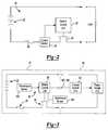
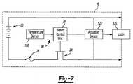
Figure 1 is a perspective view of exemplary power tools, a battery pack and a charger according to the principles of the present disclosure;Figure 2 is a circuit diagram of an overcurrent protection mechanism according to the principles of the present disclosure;Figure 3 is a circuit diagram of a battery pack and a charger according to the principles of the present disclosure;Figure 4 is a flowchart illustrating the logic of a shutdown mechanism and reset mechanism according to the principles of the present disclosure;Figure 5 is a circuit diagram of the battery pack and the power tool according to the principles of the present disclosure;Figure 6 is a circuit diagram of a battery pack including a reset button according to the principles of the present disclosure; andFigure 7 is a circuit diagram of a battery pack including a latch and a latch actuation sensor according to the principles of the present disclosure.- The drawings described herein are for illustration purposes only and are not intended to limit the scope of the present disclosure in any way.
- The following description is merely exemplary in nature and is not intended to limit the present disclosure, application, or uses. It should be understood that throughout the drawings, corresponding reference numerals indicate like or corresponding parts and features.
- The present disclosure can relate to a system of power tools of the type that is generally indicated by
reference numeral 10 inFigure 1 . The system ofpower tools 10 can include, for example, one ormore power tools 12, abattery pack 16 and abattery pack charger 18. Each of thepower tools 12 can be any type of power tool, including without limitation drills, drill/drivers, hammer drill/drivers, rotary hammers, screwdrivers, impact drivers, circular saws, jig saws, reciprocating saws, band saws, cut-off tools, cut-out tools, shears, sanders, vacuums, lights, routers, adhesive dispensers, concrete vibrators, lasers, staplers and nailers. In the particular example provided, the system ofpower tools 10 includes afirst power tool 12a and asecond power tool 12b. For example, thefirst power tool 12a can be a drill/driver similar to that which is described inU.S. Patent No. 6,431,289 , while thesecond power tool 12b can be a circular saw similar to that which is described inU.S. Patent No. 6,996,909 . - The
battery pack 16 can be selectively removably coupled to the first andsecond power tools battery pack 16 can be configured in a manner that is similar to that which is described inU.S. Patent Application Publication No. 2006/0096771 . Thebattery pack 16 can also be selectively electrically coupled to thebattery pack charger 18 to charge thebattery pack 16. It is noteworthy that the broader aspects of this disclosure are applicable to other types of battery powered devices. Figure 2 illustrates an exemplary circuit configuration for anovercurrent protection mechanism 20 integrated into abattery pack 16. Theovercurrent protection mechanism 20 is comprised generally ofbattery cells 22, aswitch 24 for controlling discharge of the battery cells, acurrent sensor 25, and abattery control unit 26. Theovercurrent protection mechanism 20 may also include afuse 28 placed in series with the battery cells. Each of these components is preferably integrated into thebattery pack 16. However, it is envisioned that one or more of these components, excluding the battery cells, may be located in a battery charger, a power tool or some other external device operably coupled to thebattery pack 16.- The
battery pack 16 may include a plurality ofbattery cells 22 connected in series, and/or a plurality of serially-connected strings of cells, in which the strings are in parallel with one another. For purposes of describing the exemplary embodiments, thebattery pack 16 may be composed of cells having lithium-ion cell chemistry. In the context of cordless power tools, the nominal voltage rating of the battery pack is typically 18 volts. However, other voltage ratings are contemplated for different applications. In addition, thebattery pack 16 may be composed of cells of a different lithium-based chemistry, such as lithium metal or lithium polymer, or another chemistry such as nickel cadmium (NiCd), nickel metal hydride (NiMH) and lead-acid, for example, in terms of the chemistry makeup of individual cells, electrodes and electrolyte of the pack. Although not limited thereto, thebattery pack 16 is preferably rechargeable. - A
battery control unit 26 embedded within thebattery pack 16 is responsible for protecting the battery cells and monitoring any fault conditions which may develop. In an exemplary embodiment, thebattery control unit 26 is implemented in software on a digital microcontroller. However, thebattery control unit 26 may be embodied in hardware or software as a digital microcontroller, a microprocessor or an analog circuit, a digital signal processor or by one or more digital ICs such as application specific integrated circuits (ASICs), for example. - Discharge current from the battery cells and charge current to the battery cells can be clamped or discontinued through the use of a
switch 24. Theswitch 24 may be placed in series with the battery cells on the low voltage side of the battery cells. Theswitch 24 can then be controlled by thebattery control unit 26 to interrupt current flow to/from the battery cells. In an exemplary embodiment, theswitch 24 is a transistor (e.g., a MOSFET). Other types of switches are also contemplated by this disclosure. - With reference to
Figures 1 ,3 and4 , thepower tool 12 and/or thebattery pack 16 may include atemperature shutdown mechanism 90. Thetemperature shutdown mechanism 90 limits the current drawn from thebattery pack 16 once thebattery pack 16 orpower tool 12 becomes overheated. In an exemplary configuration,temperature shutdown mechanism 90 may be implemented by atemperature sensor 100 disposed proximate tobattery cells 22 and thebattery control unit 26 residing withinbattery pack 16. It is contemplated that a similar temperature shutdown mechanism may be implemented in thepower tool 12. - The
temperature sensor 100 is operable to measure the temperature proximate to thebattery cells 22 and communicate a signal indicative of the measured temperatures to thebattery control unit 26. Thetemperature sensor 100 can be implemented with a negative temperature coefficient (NTC) thermistor, a positive temperature coefficient (PTC) thermistor, temperature sensing integrated circuits, or thermocouples. - Amongst other functions, the
battery control unit 26 is operable to monitor the measured temperature in relation to a predetermined threshold. When the temperature exceeds the threshold, thebattery control unit 26 opensswitch 24, thereby interrupting current flow to/from thebattery cells 22. Oncebattery pack 16 shuts down due to overheating, it generally takes a period of time forbattery pack 16 to cool. While the following description makes reference to a thermal shutdown condition, it is contemplated that the reset feature described below and other aspects of this disclosure work in conjunction with other types of shutdown conditions. - The
system 10 may include a reset feature to protect the enduser from unexpectedly starting thepower tool 12 after a thermal shutdown event. In an exemplary embodiment, thebattery control unit 26 maintains an indication of a thermal shutdown event. When a thermal shutdown event occurs, thebattery control unit 26 sets the indicator to a disable state. Thebattery control unit 26 may also receive a message indicative of a thermal shutdown event occurring in the tool and set the indicator in response to this message. The indicator must be reset to an operational state before current flow from the battery may resume. Various techniques for resetting the indicator are contemplated by this disclosure. - In one exemplary embodiment, the
battery pack 16 must be disconnected from thepower tool 12 and placed into abattery charger 18 before current flow from the battery is allowed to resume. Thecharger control unit 101 withincharger 18 communicates withbattery control unit 26 in thebattery pack 16 to reset the indicator. To provide communication betweenbattery control unit 26 andcharger control unit 101,terminals 103 and 105 formed onbattery pack 16 andcharger 18, respectively, may be provided. Oncebattery pack 16 is placed in thebattery charger 18, thecharger control unit 101 communicates withbattery control unit 26 to reset the indicator to an operational state. The enduser is then free to disconnectbattery pack 16 fromcharger 18 and operablycouple battery pack 16 topower tool 12. Use ofpower tool 12 may then resume. - The
battery control unit 26 may further require the temperature of the cells to return to a safe operating range before enabling the indicator to be reset. In other words, thebattery control unit 26 will reset the indicator once the temperature returns to an acceptable range and the pack has been placed in thecharger 18. Accordingly, the enduser is prevented from simply resettingbattery pack 16 and attempting to reusepower tool 12 prior to a temperature ofbattery cells 22 returning to an operational range. - To notify the enduser,
battery pack 16 orbattery charger 18 may be configured with anindicator device 104 that indicates thatbattery pack 16 has returned to an operational state.Indicator device 104 may be an audible indicator or a visible indicator. For example, an audible indicator may emit a beep or ring and a visible indicator may be an LED. Once the audible indicator or the visual indicator signal thatbattery pack 16 has returned to an operational state, the enduser may removebattery pack 16 fromcharger 18 and operablycouple battery pack 16 topower tool 12. Sincebattery pack 16 has sufficiently cooled and been reset, power may be restored topower tool 12 without delay. - The
battery pack 16,power tool 12, and/orcharger 18 may also include a detachment sensor 106 (Figures 1 and3 ). Thedetachment sensors 106 may be configured to sense thebattery pack 16 being disconnected from thepower tool 12 and/or from thecharger 18. Once thebattery pack 16 has returned to an operational temperature, the enduser may remove thebattery pack 16 from thepower tool 12 orcharger 18 to cause thedetachment sensor 106 to send a reset signal to thebattery control unit 26. Thereafter, thebattery pack 16 may be reconnected to thepower tool 12 and use of thepower tool 12 may resume. Thedetachment sensor 106 can be any suitable sensor such as an optical sensor, a magnetic sensor (e.g., a Hall sensor), a mechanical switch, or an electrical sensor that senses voltage, resistance or capacitance on theterminal 103 of thebattery pack 16, for example. - Referring now to
Figures 1 and5 , thepower tool 12 may include atrigger switch 108 disposed on or proximate to agrip 110 of thepower tool 12. Thetrigger switch 108 may be in electrical communication with a tool motor and atool control unit 111. The enduser may cycle thetrigger switch 108 of thepower tool 12 to cause thetool control unit 111 to send the reset signal to thebattery control unit 26. For example, the enduser may repeatedly actuate (or cycle) the trigger switch 108 a predetermined number of times within a predetermined amount of time to cause the reset signal to be sent to thebattery control unit 26, provided thebattery pack 16 has first returned to an operational temperature. Stated another way, once thebattery pack 16 reaches an operational temperature, the enduser can reset the indicator by cycling thetrigger switch 108 and then resume normal use of thepower tool 12 as desired. - Additionally or alternatively, the
power tool 12 may include apressure sensor 112. Thepressure sensor 112 may be disposed on thegrip 110, and may be in electrical communication with thetool control unit 111. Thepressure sensor 112 may be configured to detect handling of thepower tool 12. Thepressure sensor 112 may sense whether the enduser has handled thepower tool 12 within a predetermined amount of time. The predetermined amount of time may be between five and ten minutes, for example, or any other length of time sufficient for thebattery pack 16 to cool. In response to a thermal shutdown event, the enduser may allow thepower tool 12 to sit idly while thebattery pack 16 returns to an operational temperature. If thepressure sensor 112 determines that thepower tool 12 has not been handled for the predetermined amount of time, thebattery control unit 26 may receive the reset signal, and use of thepower tool 12 may resume. - Additionally or alternatively, the
power tool 12 and/or thebattery pack 16 may include amotion sensor 114 in electrical communication with the tool control unit 111 (Figures 1 and5 ). Themotion sensor 114 may detect whether thepower tool 12 orbattery pack 16 is being moved or is sitting idly. Themotion sensor 114 can be any suitable sensor such as, for example, an optical sensor or mechanical sensor. After a thermal shutdown event, if themotion sensor 114 determines that thepower tool 12 and/orbattery pack 16 have remained motionless for a predetermined amount of time to allow thebattery pack 16 to return to an operational temperature, thebattery control unit 26 may receive a reset signal, and use of thepower tool 12 may resume. - Referring now to
Figures 1 and6 , areset button 116 may be disposed on a housing of thebattery pack 16. Thereset button 116 may be in electrical communication with thebattery control unit 26. Once thebattery pack 16 has returned to an operational temperature after a thermal shutdown event, the enduser may depress thereset button 116 to send a reset signal to thebattery control unit 26. Thebattery control unit 26 may then reset the indicator and use of thepower tool 12 may resume. It should be appreciated that thereset button 116 may be depressed to reset the indicator while thebattery pack 16 is engaged or disengaged with thepower tool 12 or thecharger 18. - The
battery pack 16 may also include alocking device 118 operable to engage thereset button 116. Thelocking device 118 may be disposed in an outer housing of thebattery pack 16, proximate to the reset button, as schematically illustrated inFigure 1 . Thelocking device 118 may be any suitable electromechanical mechanism adapted to prevent thereset button 116 from being depressed. Thelocking device 118 may be in communication with thebattery control unit 26. In response to a thermal shutdown event, thebattery control unit 26 may cause thelocking device 118 to engage thereset button 116, thereby preventing thereset button 116 from being depressed while thebattery pack 16 is outside of the operational temperature range. Once thebattery pack 16 returns to an operational temperature, thebattery control unit 26 may cause thelocking device 118 to disengage thereset button 116, allowing the enduser to depress thereset button 116 to reset the indicator. It is also envisioned that thereset button 116 and lockingdevice 118 could be disposed on thepower tool 12 and/or thecharger 18. - Referring now to
Figures 1 and7 , thebattery pack 16 may include alatch 120 adapted to releasably secure thebattery pack 16 to thepower tool 12. Alatch actuation sensor 122 may detect whether thelatch 120 is engaging thepower tool 12. Thelatch actuation sensor 122 may be an optical sensor, a magnetic sensor (e.g., a Hall sensor), a mechanical sensor, an electrical sensor or any other suitable sensor. Thelatch actuation sensor 122 may be in electrical communication with thebattery control unit 26. - The
system 10 may be configured such that disengagement of thelatch 120 from thepower tool 12 causes thebattery control unit 26 to receive the reset signal. For example, once thebattery pack 16 returns to an operational temperature after a thermal shutdown event, the enduser may disengage thebattery pack 16 from thepower tool 12 by actuating thelatch 120. Thelatch actuation sensor 122 may sense thelatch 120 disengaging thepower tool 12 and send the reset signal to thebattery control unit 26. Thebattery control unit 26 may then close theswitch 24 to enable current flow to and from thebattery pack 16. - It should be understood that a thermal shutdown event includes conditions whereby the
battery pack 16 rises above or drops below an operational temperature range. Accordingly, thetemperature shutdown mechanism 90 may cause a thermal shutdown event in response to thebattery pack 16 being too cold. The various reset mechanisms described herein may be subsequently applied to enable or restore current flow to and from thebattery pack 16 after thebattery pack 16 warms up to a temperature within the operational temperature range of thebattery pack 16.
Claims (2)
- A battery pack comprising:a plurality of battery cells (22);a switch (24) in series with the battery cells (22);a temperature sensor (100) configured to senser a temperature in the battery pack; anda battery control unit (26) adapted to receive a signal indicative of the sensed temperature from the temperature sensor (100) and operable to control the switch (24) to interrupt current flow from the battery cells (22) when the sensed temperature exceeds an over-temperature threshold,wherein the battery control unit (26) is adapted to receive a separate reset signal and also operable to control the switch (24) to restore current flow upon receipt of the reset signal while the temperature is below a first operating temperature thresholdwherein there is provided a user-actuated reset mechanism accessible on an exterior of the battery pack (16) to generate the reset signal;wherein the reset mechanism comprises a button (116) the depression of which sends the reset signal to the battery control unit (26);characterised in thatthere is provided a locking mechanism (118) that prevents compression of the button (116) when the temperature exceeds the first operating temperature threshold;wherein the locking mechanism (118) is an electromechanical mechanism in communication with the battery control unit (26) which is adapted to prevent the reset button (116) from being depressed in response to a thermal shut down event while the sensed temperature is outside an operational temperature range.
- The battery pack of claim 1, wherein the battery control unit (26) controls the switch (24) to restore current flow when the temperature is above a second operating temperature threshold and the battery control unit (26) has received the reset signal.
Applications Claiming Priority (1)
| Application Number | Priority Date | Filing Date | Title |
|---|---|---|---|
| US95958307P | 2007-07-13 | 2007-07-13 |
Publications (3)
| Publication Number | Publication Date |
|---|---|
| EP2015421A2 EP2015421A2 (en) | 2009-01-14 |
| EP2015421A3 EP2015421A3 (en) | 2013-06-12 |
| EP2015421B1true EP2015421B1 (en) | 2016-03-09 |
Family
ID=39855058
Family Applications (1)
| Application Number | Title | Priority Date | Filing Date |
|---|---|---|---|
| EP08160146.0ACeasedEP2015421B1 (en) | 2007-07-13 | 2008-07-10 | Reset mechanism for a battery pack |
Country Status (3)
| Country | Link |
|---|---|
| US (1) | US8129955B2 (en) |
| EP (1) | EP2015421B1 (en) |
| CN (1) | CN201266841Y (en) |
Families Citing this family (48)
| Publication number | Priority date | Publication date | Assignee | Title |
|---|---|---|---|---|
| ES2539578T3 (en) | 2005-08-10 | 2015-07-02 | C.R. Bard, Inc. | Multi-sample biopsy device and single insert with various transport systems |
| EP3417792B1 (en) | 2006-08-21 | 2022-03-02 | C. R. Bard, Inc. | Self-contained handheld biopsy needle |
| SI2086418T1 (en) | 2006-10-06 | 2011-05-31 | Bard Peripheral Vascular Inc | Tissue handling system with reduced operator exposure |
| US8262586B2 (en) | 2006-10-24 | 2012-09-11 | C. R. Bard, Inc. | Large sample low aspect ratio biopsy needle |
| TWI340515B (en)* | 2006-12-01 | 2011-04-11 | O2Micro Int Ltd | Battery pack, electronic system with cell monitoring and the method for battery pack monitoring thereof |
| US7800510B2 (en)* | 2007-11-30 | 2010-09-21 | O2Micro, Inc. | Battery systems with embedded cell monitors |
| US8241225B2 (en) | 2007-12-20 | 2012-08-14 | C. R. Bard, Inc. | Biopsy device |
| KR101016825B1 (en)* | 2009-02-24 | 2011-02-21 | 삼성에스디아이 주식회사 | Battery pack and over discharge protection method |
| JP2010246225A (en)* | 2009-04-03 | 2010-10-28 | Sony Corp | Battery pack and charging method |
| US20100263852A1 (en)* | 2009-04-21 | 2010-10-21 | Trapeze Networks, Inc. | Heat management for enclosed electronics |
| US9173641B2 (en) | 2009-08-12 | 2015-11-03 | C. R. Bard, Inc. | Biopsy apparatus having integrated thumbwheel mechanism for manual rotation of biopsy cannula |
| US8283890B2 (en)* | 2009-09-25 | 2012-10-09 | Bard Peripheral Vascular, Inc. | Charging station for battery powered biopsy apparatus |
| US8430824B2 (en) | 2009-10-29 | 2013-04-30 | Bard Peripheral Vascular, Inc. | Biopsy driver assembly having a control circuit for conserving battery power |
| US8179276B2 (en)* | 2009-09-29 | 2012-05-15 | Tyco Healthcare Group Lp | Battery assembly with alarm |
| CN101750162B (en)* | 2009-11-12 | 2012-05-23 | 华为终端有限公司 | Method, device and terminal for detection of terminal abnormal heating |
| JP5662105B2 (en) | 2010-10-26 | 2015-01-28 | 株式会社マキタ | Secondary battery pack |
| CN102632485B (en)* | 2011-02-13 | 2015-07-15 | 南京德朔实业有限公司 | Power tool |
| JP5799221B2 (en)* | 2011-03-23 | 2015-10-21 | パナソニックIpマネジメント株式会社 | Electric tool |
| WO2013063507A1 (en) | 2011-10-26 | 2013-05-02 | Milwaukee Electric Tool Corporation | Wireless tracking of power tools and related devices |
| CN102729224B (en)* | 2012-07-05 | 2016-04-27 | 南京德朔实业有限公司 | There is the electric tool of auxiliary bouncing out battery packet function |
| CA2902221A1 (en) | 2013-03-20 | 2014-09-25 | Bard Peripheral Vascular, Inc. | Biopsy device |
| CN203504217U (en)* | 2013-09-10 | 2014-03-26 | 向智勇 | electronic cigarette case |
| ES2726985T3 (en) | 2013-11-05 | 2019-10-11 | Bard Inc C R | Biopsy device that has integrated vacuum |
| US20150239086A1 (en)* | 2014-02-25 | 2015-08-27 | Chao-Ying LEE | Electrical Power Safety System |
| US9928188B2 (en)* | 2014-06-18 | 2018-03-27 | MediaLeash, LLC | Battery pack to regulate access to media systems |
| JP2016022566A (en)* | 2014-07-23 | 2016-02-08 | 株式会社マキタ | Electric machine apparatus |
| WO2016178656A1 (en) | 2015-05-01 | 2016-11-10 | C. R. Bard, Inc. | Biopsy device |
| EP3846492A1 (en) | 2015-05-04 | 2021-07-07 | Milwaukee Electric Tool Corporation | Power tool and method for wireless communication |
| US20170033585A1 (en)* | 2015-07-31 | 2017-02-02 | Semiconductor Components Industries, Llc | Battery system reset systems and related methods |
| WO2017112898A1 (en)* | 2015-12-22 | 2017-06-29 | Inovio Pharmaceuticals, Inc. | Electroporation device having a battery pack with power switch |
| CN105573214A (en)* | 2016-01-18 | 2016-05-11 | 江苏工程职业技术学院 | Control method and charging method for multifunctional charger baby |
| AU201615156S (en) | 2016-03-17 | 2016-12-09 | Tti Macao Commercial Offshore Ltd | Battery pack |
| AU201615158S (en) | 2016-03-17 | 2016-12-09 | Tti Macao Commercial Offshore Ltd | Battery pack |
| AU201615153S (en) | 2016-03-17 | 2016-12-09 | Tti Macao Commercial Offshore Ltd | Battery pack |
| US10680494B2 (en) | 2016-06-24 | 2020-06-09 | Black & Decker Inc. | Control scheme for power tool having a brushless motor |
| WO2018001746A1 (en) | 2016-06-29 | 2018-01-04 | Philip Morris Products S.A. | Battery powered aerosol-generating device comprising a temperature dependent battery pre-heating |
| US10491020B2 (en) | 2016-12-22 | 2019-11-26 | Milwaukee Electric Tool Corporation | Power source for burst operation |
| USD853813S1 (en) | 2017-01-17 | 2019-07-16 | Tti (Macao Commercial Offshore) Limited | Power tool |
| USD853216S1 (en) | 2017-01-17 | 2019-07-09 | Tti (Macao Commercial Offshore) Limited | Power tool |
| USD926674S1 (en) | 2017-01-17 | 2021-08-03 | Tti (Macao Commercial Offshore) Limited | Battery pack with communication terminal |
| TWD200632S (en) | 2017-01-17 | 2019-11-01 | Tti Macao Commercial Offshore Ltd | Battery pack |
| JP7193403B2 (en) | 2019-03-29 | 2022-12-20 | 株式会社マキタ | Power supply device, electric work machine system |
| WO2021016080A1 (en)* | 2019-07-19 | 2021-01-28 | Milwaukee Electric Tool Corporation | Resettable electronic fuse for high-power devices |
| WO2021030549A1 (en) | 2019-08-13 | 2021-02-18 | Milwaukee Electric Tool Corporation | Credentialed wireless fob to control power tool devices |
| JP7477405B2 (en)* | 2020-09-14 | 2024-05-01 | 株式会社マキタ | Charger |
| EP4338277A4 (en)* | 2021-05-13 | 2025-05-07 | Black & Decker Inc. | POWER TOOL BATTERY PACK |
| CN116207328B (en)* | 2022-12-30 | 2024-06-04 | 珠海泰坦新动力电子有限公司 | A locking and pressurizing device and a pressurizing and depressurizing method |
| WO2024242458A1 (en)* | 2023-05-25 | 2024-11-28 | 삼성전자 주식회사 | Wireless cleaner device employing overheating prevention method |
Family Cites Families (28)
| Publication number | Priority date | Publication date | Assignee | Title |
|---|---|---|---|---|
| DE69512254T2 (en)* | 1994-05-19 | 2000-04-20 | Koninklijke Philips Electronics N.V. | CHARGING DEVICE FOR CHARGING RECHARGEABLE BATTERIES WITH A TEMPERATURE-DEPENDENT TERMINATION OF THE CHARGE PROCESS AND RECHARGEABLE BATTERY WITH A TEMPERATURE-INDICATING STRIP |
| US5625273A (en) | 1994-12-30 | 1997-04-29 | Bren-Tronics Inc. | Battery safety device |
| JPH10100079A (en)* | 1996-09-30 | 1998-04-21 | Sanyo Electric Co Ltd | Battery pack for power tools |
| SE516507C2 (en) | 1996-12-23 | 2002-01-22 | Ericsson Telefon Ab L M | Rechargeable battery with built-in safety circuit for a portable electrical appliance |
| US6025699A (en) | 1997-12-12 | 2000-02-15 | Dell Usa, L.P. | Self discharge of batteries at high temperatures |
| US6996909B1 (en) | 1998-08-13 | 2006-02-14 | Black & Decker Inc. | Battery powered circular saw |
| US6243276B1 (en)* | 1999-05-07 | 2001-06-05 | S-B Power Tool Company | Power supply system for battery operated devices |
| JP2001178011A (en)* | 1999-12-10 | 2001-06-29 | Toshiba Battery Co Ltd | Secondary battery device |
| JP3638109B2 (en) | 2000-02-07 | 2005-04-13 | Necトーキン栃木株式会社 | Battery pack |
| JP3743704B2 (en) | 2000-09-25 | 2006-02-08 | Necトーキン栃木株式会社 | Battery pack |
| JP3468220B2 (en) | 2000-12-26 | 2003-11-17 | 株式会社リコー | Charge / discharge protection circuit, battery pack incorporating the charge / discharge protection circuit, and electronic device using the battery pack |
| US6431289B1 (en) | 2001-01-23 | 2002-08-13 | Black & Decker Inc. | Multi-speed power tool transmission |
| DE10214364A1 (en) | 2002-03-30 | 2003-10-16 | Bosch Gmbh Robert | Monitoring device, power tool, power supply device and associated operating method |
| DE10246761A1 (en) | 2002-10-07 | 2004-04-15 | Hilti Ag | Battery-operated electric hand tool has control module with electronic power stage integrated in interchangeable battery pack |
| FR2862558B1 (en) | 2003-11-20 | 2006-04-28 | Pellenc Sa | POWER AUTONOMOUS POWER PORTABLE TOOL |
| US6928381B2 (en)* | 2003-12-17 | 2005-08-09 | The Boeing Company | Battery overtemperature control system and method |
| EP1758226A1 (en) | 2004-06-16 | 2007-02-28 | Murata Manufacturing Co., Ltd. | Battery pack protecting circuit and battery pack |
| DE102004031601A1 (en) | 2004-06-30 | 2006-02-09 | Hilti Ag | Battery pack for electric hand tool |
| CN201515238U (en)* | 2004-10-18 | 2010-06-23 | 布莱克和戴克公司 | Cordless power tool system and battery pack for cordless power tool system |
| US7273159B2 (en) | 2004-11-08 | 2007-09-25 | Black & Decker Inc. | Cordless power tool system with improved power output |
| KR100584404B1 (en)* | 2004-11-11 | 2006-05-26 | 삼성전자주식회사 | Battery device of mobile communication terminal and its operation method |
| DE102005020377B4 (en) | 2005-05-02 | 2021-08-12 | Robert Bosch Gmbh | Method for operating an electric machine tool |
| JP5122750B2 (en) | 2006-02-23 | 2013-01-16 | パナソニック株式会社 | Electric tool |
| ATE437464T1 (en) | 2006-04-04 | 2009-08-15 | Metabowerke Gmbh | BATTERY PACK FOR A HAND-HELD ELECTRICAL TOOL |
| DE102006017369A1 (en) | 2006-04-11 | 2007-10-18 | Robert Bosch Gmbh | Electric hand tool with Ausschaltverzögerungsvorrichtung |
| KR100807063B1 (en) | 2006-05-24 | 2008-02-25 | 삼성에스디아이 주식회사 | Battery pack |
| US7808212B2 (en) | 2006-07-24 | 2010-10-05 | Research In Motion Limited | Temperature-based charge and discharge control for a battery |
| US7486049B2 (en) | 2006-10-13 | 2009-02-03 | Wan Wei-Liang | Protection circuit for lithium battery pack serving as tool power source |
- 2008
- 2008-07-10EPEP08160146.0Apatent/EP2015421B1/ennot_activeCeased
- 2008-07-10USUS12/170,486patent/US8129955B2/enactiveActive
- 2008-07-14CNCNU2008201370203Upatent/CN201266841Y/ennot_activeExpired - Fee Related
Also Published As
| Publication number | Publication date |
|---|---|
| US8129955B2 (en) | 2012-03-06 |
| CN201266841Y (en) | 2009-07-01 |
| EP2015421A2 (en) | 2009-01-14 |
| US20090015208A1 (en) | 2009-01-15 |
| EP2015421A3 (en) | 2013-06-12 |
Similar Documents
| Publication | Publication Date | Title |
|---|---|---|
| EP2015421B1 (en) | Reset mechanism for a battery pack | |
| EP2017917B1 (en) | Software-implemented overcurrent protection embedded in a battery pack | |
| EP2034585B1 (en) | System and Method for Re-initiating Charge Cycle for Battery Pack Left in a Charger | |
| US20220093965A1 (en) | Method and system for battery protection | |
| US7508171B2 (en) | Protection methods, protection circuits and protective devices for secondary batteries, a power tool, charger and battery pack adapted to provide protection against fault conditions in the battery pack | |
| US7498774B2 (en) | Battery pack for hand-held electric machine tools | |
| JP2006281404A (en) | Cordless power tool | |
| EP2175514A1 (en) | Shared Control of Thermistor and Dual Purpose Thermistor Line | |
| CN1974140B (en) | Battery pack and cordless electric tool using said battery pack | |
| JP2001095158A (en) | Battery power supply and electric equipment using the same | |
| US20100173179A1 (en) | Arrangement having at least one battery | |
| JP2005245062A (en) | Charge controller and rechargeable power tool set | |
| WO2011122696A1 (en) | Battery pack and power tool using the same | |
| JP4867734B2 (en) | Lithium battery pack and combination of battery pack and power tool | |
| JP2012005288A (en) | Charger | |
| WO2024212173A1 (en) | Battery pack and circuit board assembly | |
| JP2001307779A (en) | Nonaqueous electrolyte secondary battery pack |
Legal Events
| Date | Code | Title | Description |
|---|---|---|---|
| PUAI | Public reference made under article 153(3) epc to a published international application that has entered the european phase | Free format text:ORIGINAL CODE: 0009012 | |
| AK | Designated contracting states | Kind code of ref document:A2 Designated state(s):AT BE BG CH CY CZ DE DK EE ES FI FR GB GR HR HU IE IS IT LI LT LU LV MC MT NL NO PL PT RO SE SI SK TR | |
| AX | Request for extension of the european patent | Extension state:AL BA MK RS | |
| PUAL | Search report despatched | Free format text:ORIGINAL CODE: 0009013 | |
| AK | Designated contracting states | Kind code of ref document:A3 Designated state(s):AT BE BG CH CY CZ DE DK EE ES FI FR GB GR HR HU IE IS IT LI LT LU LV MC MT NL NO PL PT RO SE SI SK TR | |
| AX | Request for extension of the european patent | Extension state:AL BA MK RS | |
| RIC1 | Information provided on ipc code assigned before grant | Ipc:H01H 3/20 20060101ALI20130506BHEP Ipc:H01M 2/34 20060101ALI20130506BHEP Ipc:B25F 5/00 20060101ALI20130506BHEP Ipc:H01H 73/30 20060101ALI20130506BHEP Ipc:H02J 7/00 20060101AFI20130506BHEP Ipc:H02H 5/04 20060101ALI20130506BHEP | |
| 17P | Request for examination filed | Effective date:20131118 | |
| RBV | Designated contracting states (corrected) | Designated state(s):AT BE BG CH CY CZ DE DK EE ES FI FR GB GR HR HU IE IS IT LI LT LU LV MC MT NL NO PL PT RO SE SI SK TR | |
| AKX | Designation fees paid | Designated state(s):DE GB | |
| 17Q | First examination report despatched | Effective date:20140416 | |
| GRAP | Despatch of communication of intention to grant a patent | Free format text:ORIGINAL CODE: EPIDOSNIGR1 | |
| INTG | Intention to grant announced | Effective date:20150901 | |
| GRAS | Grant fee paid | Free format text:ORIGINAL CODE: EPIDOSNIGR3 | |
| GRAA | (expected) grant | Free format text:ORIGINAL CODE: 0009210 | |
| AK | Designated contracting states | Kind code of ref document:B1 Designated state(s):DE GB | |
| REG | Reference to a national code | Ref country code:GB Ref legal event code:FG4D | |
| REG | Reference to a national code | Ref country code:DE Ref legal event code:R096 Ref document number:602008042648 Country of ref document:DE | |
| REG | Reference to a national code | Ref country code:DE Ref legal event code:R097 Ref document number:602008042648 Country of ref document:DE | |
| PLBE | No opposition filed within time limit | Free format text:ORIGINAL CODE: 0009261 | |
| STAA | Information on the status of an ep patent application or granted ep patent | Free format text:STATUS: NO OPPOSITION FILED WITHIN TIME LIMIT | |
| 26N | No opposition filed | Effective date:20161212 | |
| PGFP | Annual fee paid to national office [announced via postgrant information from national office to epo] | Ref country code:GB Payment date:20210616 Year of fee payment:14 | |
| PGFP | Annual fee paid to national office [announced via postgrant information from national office to epo] | Ref country code:DE Payment date:20220517 Year of fee payment:15 | |
| GBPC | Gb: european patent ceased through non-payment of renewal fee | Effective date:20220710 | |
| PG25 | Lapsed in a contracting state [announced via postgrant information from national office to epo] | Ref country code:GB Free format text:LAPSE BECAUSE OF NON-PAYMENT OF DUE FEES Effective date:20220710 | |
| REG | Reference to a national code | Ref country code:DE Ref legal event code:R119 Ref document number:602008042648 Country of ref document:DE | |
| PG25 | Lapsed in a contracting state [announced via postgrant information from national office to epo] | Ref country code:DE Free format text:LAPSE BECAUSE OF NON-PAYMENT OF DUE FEES Effective date:20240201 |