EP2015247B1 - Method and system for supplying in a standard format information formatted for image processing means - Google Patents
Method and system for supplying in a standard format information formatted for image processing meansDownload PDFInfo
- Publication number
- EP2015247B1 EP2015247B1EP08100657.9AEP08100657AEP2015247B1EP 2015247 B1EP2015247 B1EP 2015247B1EP 08100657 AEP08100657 AEP 08100657AEP 2015247 B1EP2015247 B1EP 2015247B1
- Authority
- EP
- European Patent Office
- Prior art keywords
- image
- defects
- formatted information
- parameters
- restitution
- Prior art date
- Legal status (The legal status is an assumption and is not a legal conclusion. Google has not performed a legal analysis and makes no representation as to the accuracy of the status listed.)
- Expired - Lifetime
Links
Images


Classifications
- G—PHYSICS
- G06—COMPUTING OR CALCULATING; COUNTING
- G06T—IMAGE DATA PROCESSING OR GENERATION, IN GENERAL
- G06T5/00—Image enhancement or restoration
- G—PHYSICS
- G06—COMPUTING OR CALCULATING; COUNTING
- G06T—IMAGE DATA PROCESSING OR GENERATION, IN GENERAL
- G06T1/00—General purpose image data processing
- G06T1/0007—Image acquisition
- G—PHYSICS
- G06—COMPUTING OR CALCULATING; COUNTING
- G06T—IMAGE DATA PROCESSING OR GENERATION, IN GENERAL
- G06T3/00—Geometric image transformations in the plane of the image
- G06T3/10—Selection of transformation methods according to the characteristics of the input images
- G—PHYSICS
- G06—COMPUTING OR CALCULATING; COUNTING
- G06T—IMAGE DATA PROCESSING OR GENERATION, IN GENERAL
- G06T5/00—Image enhancement or restoration
- G06T5/70—Denoising; Smoothing
- G—PHYSICS
- G06—COMPUTING OR CALCULATING; COUNTING
- G06T—IMAGE DATA PROCESSING OR GENERATION, IN GENERAL
- G06T5/00—Image enhancement or restoration
- G06T5/73—Deblurring; Sharpening
- G—PHYSICS
- G06—COMPUTING OR CALCULATING; COUNTING
- G06T—IMAGE DATA PROCESSING OR GENERATION, IN GENERAL
- G06T5/00—Image enhancement or restoration
- G06T5/80—Geometric correction
- H—ELECTRICITY
- H04—ELECTRIC COMMUNICATION TECHNIQUE
- H04N—PICTORIAL COMMUNICATION, e.g. TELEVISION
- H04N1/00—Scanning, transmission or reproduction of documents or the like, e.g. facsimile transmission; Details thereof
- H04N1/00002—Diagnosis, testing or measuring; Detecting, analysing or monitoring not otherwise provided for
- H04N1/00007—Diagnosis, testing or measuring; Detecting, analysing or monitoring not otherwise provided for relating to particular apparatus or devices
- H—ELECTRICITY
- H04—ELECTRIC COMMUNICATION TECHNIQUE
- H04N—PICTORIAL COMMUNICATION, e.g. TELEVISION
- H04N1/00—Scanning, transmission or reproduction of documents or the like, e.g. facsimile transmission; Details thereof
- H04N1/00002—Diagnosis, testing or measuring; Detecting, analysing or monitoring not otherwise provided for
- H04N1/00026—Methods therefor
- H04N1/00045—Methods therefor using a reference pattern designed for the purpose, e.g. a test chart
- H—ELECTRICITY
- H04—ELECTRIC COMMUNICATION TECHNIQUE
- H04N—PICTORIAL COMMUNICATION, e.g. TELEVISION
- H04N1/00—Scanning, transmission or reproduction of documents or the like, e.g. facsimile transmission; Details thereof
- H04N1/00002—Diagnosis, testing or measuring; Detecting, analysing or monitoring not otherwise provided for
- H04N1/00071—Diagnosis, testing or measuring; Detecting, analysing or monitoring not otherwise provided for characterised by the action taken
- H—ELECTRICITY
- H04—ELECTRIC COMMUNICATION TECHNIQUE
- H04N—PICTORIAL COMMUNICATION, e.g. TELEVISION
- H04N1/00—Scanning, transmission or reproduction of documents or the like, e.g. facsimile transmission; Details thereof
- H04N1/387—Composing, repositioning or otherwise geometrically modifying originals
- H—ELECTRICITY
- H04—ELECTRIC COMMUNICATION TECHNIQUE
- H04N—PICTORIAL COMMUNICATION, e.g. TELEVISION
- H04N1/00—Scanning, transmission or reproduction of documents or the like, e.g. facsimile transmission; Details thereof
- H04N1/40—Picture signal circuits
- H04N1/40093—Modification of content of picture, e.g. retouching
- H—ELECTRICITY
- H04—ELECTRIC COMMUNICATION TECHNIQUE
- H04N—PICTORIAL COMMUNICATION, e.g. TELEVISION
- H04N1/00—Scanning, transmission or reproduction of documents or the like, e.g. facsimile transmission; Details thereof
- H04N1/46—Colour picture communication systems
- H04N1/56—Processing of colour picture signals
- H04N1/58—Edge or detail enhancement; Noise or error suppression, e.g. colour misregistration correction
Definitions
- the present inventionrelates to a method and a system for providing, in a standard format, formatted information to image processing means.
- the formatted informationis at least partly formatted information measured.
- the differencesare small.
- the formatted informationis at least partly expanded formatted information.
- the formatted informationoccupies little memory. Also, image processing calculations are faster.
- the systemis such that the field is relative to the sharpness defects of the image restoration apparatus.
- the systemis such that the field contains at least one value relating to the dive defects of the apparatus of the image rendering apparatus.
- the systemis such that the field is relative to the colorimetric defects of the image restitution apparatus.
- the systemis such that the field contains at least one value relating to the colorimetric defects of the image restoration apparatus.
- FIG. 6there is shown a flow diagram implementing an image 103, a real reproduction projection 90 giving a restored image 191 of the image 103 for the restitution characteristics used 95, a parameterizable restitution transformation model 97 giving a corrected restitution image 94 of Fig. 103, a mathematical rendering projection 96 giving a mathematical rendering image 92 of the corrected rendering image 94 and having a rendering difference 93 with the rendered image 191.
- An image capture apparatus 1is an apparatus consisting of an optical 100, one or more sensors 101, a 102, of a memory zone 16. Said apparatus for image capture 1 allows from a scene 3 to obtain fixed digital images 103 or animated recorded in the memory zone 16 or transmitted to an external device. Animated images consist of a succession in time, still images 103. Said image capture apparatus 1 may take the form of a camera, a camcorder, a connected or integrated camera. a PC, a camera connected to or integrated with a personal assistant, a camera connected to or integrated with a telephone, a videoconferencing device or a camera or measuring device that is sensitive to other lengths of wave than those of visible light such as a thermal camera.
- image rendering means 19may take the form of a display screen, a television, a flat screen, a projector, virtual reality glasses, printer.
- Pixel 104is called an elementary zone of the surface of the sensor 110 obtained by creating a generally regular tiling of said surface of the sensor 110.
- a pixel valueis called a number associated with this pixel 104.
- the mathematical projection 8is defined in the manner that will be described below.
- the actual shape 51 associated with said viewing direction 106is not a point on the surface of the sensor, but has a three-dimensional space cloud shape, which intersects with one or more pixels 104.
- the differencesare due to coma, spherical aberration, astigmatism, pixel clustering 104, chromatic aberration, depth of field, diffraction, spurious reflections, the field curvature of the camera.
- the actual projection 72 of the scene 3is constituted by the set of real points.
- Inverse parameterizable transformation model 212(or in a condensed manner, inverse parameterizable transformation 212) is called a mathematical transformation that makes it possible to obtain an image 103 from a corrected image 71 and the value of parameters 103. in particular be calculated from the characteristics used 74 as indicated below.
- the parametersmay include in particular: the focal length of the optics 100 of the configuration used or a linked value such as the position of a lens group, the focusing of the optics 100 of the configuration used or a linked value such as the position of a lens group, opening optics 100 of the configuration used or a bound value such as the position of the diaphragm.
- a reference scene 9is called a scene 3 of which certain characteristics are known.
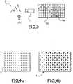
- the figure 4apresents a reference scene 9 consisting of a sheet of paper having circles filled with black and arranged regularly.
- the figure 4bpresents another sheet of paper with the same circles to which are added lines and colored surfaces. The circles are used to measure the actual position 50 of a point, the lines the actual shape of a point, the colored surfaces the actual color of a point, and the actual intensity of a point.
- This reference scene 9may be made of a material other than paper.
- synthesis image 207a mathematical image 70 obtained by mathematical projection 8 of a reference scene 9. of synthetic images 7, a set of mathematical images 70 obtained by mathematical projection 8 of one or more reference scenes 9, for one or more sets of characteristics used 74.
- the synthesis image class 7only comprises a synthesis image 207.
- Calibrationcan alternatively be performed by the user of the device for each device and configuration in case 1.
- Calibrationcan alternatively be performed by the user of the device, for each optical 100 and type of device in case 3.
- Characteristic database 22is a database comprising, for one or more image capture apparatuses 1 and for one or more images 103, formatted information 15.
- Said divefurther includes the depth of field blur, including spherical aberrations, coma, astigmatism.
- Said blurdepends on the distance of the points of the scene 3 with respect to the image-capture apparatus 1 and is characterized by the parameters associated with the characteristics of the shot 74 and a parameterizable transformation representing the characteristics of the camera image capture 1 at the time of shooting. Said parameters and said parameterizable transformation make it possible to calculate the corrected shape of a point of the image 103.
- Step (d)further provides the digital processing parameters performed by the image capture apparatus 1. These parameters are determined by manual or automatic adjustments made.
- the apparatus P25for capturing or restoring an image on a support.
- the apparatus P25comprises at least one fixed characteristic and / or a variable characteristic according to the image.
- the fixed characteristic and / or variable characteristicis likely to be associated with one or more characteristic values, in particular focal length and / or focus and their associated characteristic values.
- the methodincludes the step of producing measured formatted information related to geometric distortions of the apparatus from a measured field.
- the formatted informationmay include the measured formatted information.
- the device chain P3comprises at least one image-capture apparatus and / or at least one image-reproduction apparatus 19.
- the image-processing means P1implement formatted information related to the defects P5 d at least one apparatus of the P5 appliance chain.
- the formatted information 15depends on at least one variable.
- WO 03007243In this application, there is described a method for calculating a transformed image from a digital image and formatted information relating to defects P5 of a P3 appliance chain. comprises an image capture apparatus and / or an image rendering apparatus, wherein the apparatus line P3 comprises at least one apparatus P.
- the methodcomprises the step of automatically determining characteristic data from the formatted information. and / or digital image.It results from the combination of technical features that the image transformed has no visible or troublesome defect, including noise-related defects, for its subsequent use.
- image processing means P1for example an image processing software 4 and / or a component and / or an equipment and / or a system making it possible to modify the quality of the image, may be used.
- image 103by implementing formatted information 15, in order to produce a modified image, for example a corrected image 71 or a corrected rendering image 97.
- the modified imagecan be intended for a second device of the P3 appliance chain. whether or not separate from the apparatus P25, for example the next apparatus in the P3 appliance chain.
- the correction methodis the method implemented by an image processing means P1 for modifying the quality of the images according to the defect P5.
- the apparatus P25corrects its own defects P5
- the apparatuses P25 of the appliance chain P3can be determined by construction, by example in a fax machine: a scanner and a printer; however, the user may use only part of the P25 devices in the P3 device chain, for example if the fax machine can also be used as a single printer.
- the image processing means P1are integrated in a computer, in practice the image processing means P1 are compatible with multiple apparatus P25, and at least one apparatus P25 of the appliance chain P3 can vary. from one image 103 to another.
- variable characteristics P6are examples of variable characteristics P6.
- the formatted informationmay depend on at least one variable characteristic P6.
- variable characteristic P6can also be called the variable rendering characteristic.
- variable characteristic value P26is called the value of variable characteristic P6 at the time of capture, modification or reproduction of a given image, obtained for example from data in Exif format present in file P100.
- the image processing means P1can then process or modify the quality of the image 103 as a function of the variable characteristics P6, by using formatted information dependent on the variable characteristics P6 and by determining the value of the variable characteristics P26.
- variable characteristic value P6can also be called the variable rendition characteristic value.
- the formatted information or a fraction of the formatted informationmay comprise measured formatted information P101, as shown in FIG. figure 15 , to represent a raw measurement, for example a mathematical field related to geometric distortion defects at a number of characteristic points of a grid 80.
- the formatted information or a fraction of the formatted informationmay comprise expanded formatted information P102, as represented on the figure 15 , which can be calculated from the measured formatted information P101, for example by interpolation for the other real points than the characteristic points of the grid 80.
- formatted informationcould depend on variable characteristics P6.
- the inventionprovides for computing the formatted information as expanded form information P102 by interpolation from measured formatted information P101 relating to a predetermined selection of the known P120 variable characteristic combinations P120.
- the measured formatted information P101 and the expanded formatted information P102may have interpolation deviation P121.
- the inventionmay comprise the step of selecting zero, one or more of the variable characteristics P6, such that the interpolation deviation P121, for the extended formatted information P102 obtained for the variable characteristics P6 thus selected, is less than at a predetermined interpolation threshold.
- some variable characteristics P6may have a lower influence on the P5 defect than others and to make the approximation that they are constant may introduce only a minimal error; for example, the focus setting may have only a slight influence on the vignetting defect and for this reason not be part of the selected variable characteristics P6.
- the variable characteristics P6can be selected at the time of the production of the formatted information 15.
- the modification of the quality of the imagesimplements simple calculations. It also results from the combination of technical features that the expanded formatted information P102 is compact. It also results from the combination of the technical features that the variable characteristics P6 eliminated are the least influential on the defect P5. As a result of the combination of technical features, the formatted information makes it possible to modify the quality of the images with a certain accuracy.
- the combination 120may also be called the rendition combination.
- the measured formatted information P101can also be called formatted measured restitution information.
- the expanded formatted information P102may also be called extended formatted restitution information.
- the image processing means P1can use the parameters P9 of the parameterizable transformation model P10 to calculate the modified image, for example to calculate the corrected intensity or corrected intensity of reproduction of a point of the image. 'picture.
- color plane P20 of a picture 103 in colorcan be decomposed into color planes P20 in various ways: number of planes (1, 3 or more), precision (8 unsigned bits, 16 signed bits, floating %) and meaning of the plans (with respect to a standard color space).
Landscapes
- Engineering & Computer Science (AREA)
- Multimedia (AREA)
- Signal Processing (AREA)
- Physics & Mathematics (AREA)
- General Physics & Mathematics (AREA)
- Theoretical Computer Science (AREA)
- Health & Medical Sciences (AREA)
- Biomedical Technology (AREA)
- General Health & Medical Sciences (AREA)
- Image Processing (AREA)
- Facsimile Image Signal Circuits (AREA)
- Facsimiles In General (AREA)
- Editing Of Facsimile Originals (AREA)
- Studio Devices (AREA)
- Image Analysis (AREA)
- Apparatus For Radiation Diagnosis (AREA)
- Television Signal Processing For Recording (AREA)
- Channel Selection Circuits, Automatic Tuning Circuits (AREA)
- Character Input (AREA)
- Computer And Data Communications (AREA)
- Communication Control (AREA)
- Investigating Materials By The Use Of Optical Means Adapted For Particular Applications (AREA)
- Transmitters (AREA)
- Geometry (AREA)
- Processing Or Creating Images (AREA)
- Polysaccharides And Polysaccharide Derivatives (AREA)
- Photoreceptors In Electrophotography (AREA)
- Circuits Of Receivers In General (AREA)
- Analysing Materials By The Use Of Radiation (AREA)
Abstract
Description
Translated fromFrenchLa présente invention concerne un procédé et un système pour fournir, selon un format standard, des informations formatées à des moyens de traitement d'images.The present invention relates to a method and a system for providing, in a standard format, formatted information to image processing means.
Il est connu des systèmes corrigeant la distorsion lors d'une projection d'une image sur un écran, notamment décrits dans
. Il est par ailleurs connu le format EXIF, notamment décrit dans "
L'invention est définie dans les revendications indépendants 1 et 13. Les revendications dependants définissent des modes de réalisation particulières.The invention is defined in
L'invention concerne un procédé pour fournir, selon un format standard, des informations formatées à des moyens de traitement d'images, notamment des logiciels et/ou des composants. Les informations formatées sont liées aux défauts d'une chaîne d'appareils. La chaîne d'appareils comprend notamment au moins un appareil de restitution d'image. Les moyens de traitement d'images utilisent les informations formatées pour modifier la qualité d'au moins une image provenant ou destinée à la chaîne d'appareils. Les informations formatées comportent, des données caractérisant des défauts de l'appareil de restitution des images, notamment les caractéristiques de distorsion.The invention relates to a method for providing, in a standard format, formatted information to image processing means, in particular software and / or components. Formatted information is related to defects in a device chain. The appliance chain includes in particular at least one image restoration apparatus. The image processing means uses the formatted information to modify the quality of at least one image from or intended for the appliance chain. The formatted information includes, data characterizing defects in the image rendering apparatus, including distortion characteristics.
Le procédé comprend l'étape de renseigner au moins un champ du format standard avec les informations formatées. Le champ est désigné par un nom de champ. Le champ contenant au moins une valeur de champ.The method includes the step of providing at least one field of the standard format with the formatted information. The field is designated by a field name. The field containing at least one field value.
De préférence, selon l'invention le procédé est tel que le champ est relatif aux défauts de piqué de l'appareil de restitution d'image. Le procédé est tel que le champ contient au moins une valeur relative aux défauts de piqué de l'appareil de restitution d'image.Preferably, according to the invention, the method is such that the field is relative to the sharpness defects of the image restitution apparatus. The method is such that the field contains at least one value relating to the sharpness defects of the image restitution apparatus.
De préférence, selon l'invention le procédé est tel que le champ est relatif aux défauts de colorimétrie de l'appareil de restitution d'image. Le procédé est tel que le champ contient au moins une valeur relative aux défauts de colorimétrie de l'appareil de restitution d'image.Preferably, according to the invention the method is such that the field is relative to the colorimetric defects of the image restoration apparatus. The method is such that the field contains at least one value relating to the colorimetric defects of the image restitution apparatus.
De préférence, selon l'invention le procédé est tel que le champ est relatif aux défauts géométriques de distorsion et/ou aux défauts géométriques d'aberration chromatique de l'appareil de restitution d'image. Le procédé est tel que le champ contient au moins une valeur relative aux défauts géométriques de distorsion et/ou aux défauts géométriques d'aberration chromatique de l'appareil de restitution d'image.Preferably, according to the invention, the method is such that the field is relative to the geometric distortion defects and / or geometric chromatic aberration defects of the image restitution apparatus. The method is such that the field contains at least one value relating to geometric distortion defects and / or geometric chromatic aberration defects of the image restitution apparatus.
De préférence, selon l'invention le procédé est tel que le champ est relatif aux défauts géométriques de vignetage et/ou aux défauts de contraste de l'appareil de restitution d'image. Le procédé est tel que le champ contient au moins une valeur relative aux défauts géométriques de vignetage et/ou aux défauts de contraste de l'appareil de restitution d'image.Preferably, according to the invention the method is such that the field is relative to the geometric vignetting defects and / or contrast defects of the image restoration apparatus. The method is such that the field contains at least one value relating to the geometric vignetting defects and / or contrast defects of the image rendering apparatus.
De préférence, selon l'invention le procédé est tel que le champ contient au moins une valeur relative à des écarts.Preferably, according to the invention, the method is such that the field contains at least one value relating to deviations.
De préférence, selon l'invention les informations formatées sont composées au moins en partie des paramètres d'un modèle de transformation paramétrable représentatif des défauts de piqué de l'appareil de restitution. Le procédé est tel que la ou les valeurs contenues dans le champ relatif aux défauts de piqué sont composées au moins en partie des paramètres du modèle de transformation paramétrable. Il résulte de la combinaison des traits techniques que les moyens de traitement d'image peuvent utiliser les paramètres du modèle de transformation paramétrable pour calculer la forme corrigée ou la forme corrigée de restitution d'un point de l'image.Preferably, according to the invention the formatted information is composed at least in part of the parameters of a parameterizable transformation model representative of the deviation defects of the rendering apparatus. The method is such that the value or values contained in the field relating to the dive defects are composed at least in part of the parameters of the parameterizable transformation model. It follows from the combination of the technical features that the image processing means can use the parameters of the parameterizable transformation model to calculate the corrected form or the corrected form of restitution of a point of the image.
De préférence, selon l'invention les informations formatées sont composées au moins en partie des paramètres d'un modèle de transformation paramétrable représentatif des défauts de colorimétrie de l'appareil de restitution. Le procédé est tel que la ou les valeurs contenues dans le champ relatif aux défauts de colorimétrie sont composées au moins en partie des paramètres du modèle de transformation paramétrable. Il résulte de la combinaison des traits techniques que les moyens de traitement d'image peuvent utiliser les paramètres du modèle de transformation paramétrable pour calculer la couleur corrigée ou la couleur corrigée de restitution d'un point de l'image.Preferably, according to the invention the formatted information is composed at least in part of the parameters of a parameterizable transformation model representative of the colorimetric defects of the rendering apparatus. The method is such that the value or values contained in the field relating to the colorimetric defects are composed at least in part of the parameters of the parameterizable transformation model. It follows from the combination of the technical features that the image processing means can use the parameters of the parameterizable transformation model to calculate the corrected color or the corrected color of reproduction of a point of the image.
De préférence, selon l'invention les informations formatées sont composées au moins en partie des paramètres d'un modèle de transformation paramétrable représentatif des défauts géométriques de distorsion et/ou des défauts géométriques d'aberration chromatique /ou de l'appareil de restitution. Le procédé est tel que la ou les valeurs contenues dans le champ relatif aux défauts géométriques de distorsion et/ou aux défauts géométriques d'aberration chromatique sont composées au moins en partie des paramètres du modèle de transformation paramétrable. Il résulte de la combinaison des traits techniques que les moyens de traitement d'image peuvent utiliser les paramètres du modèle de transformation paramétrable pour calculer la position corrigée ou la position corrigée de restitution d'un point de l'image.Preferably, according to the invention the formatted information is composed at least in part of the parameters of a parameterizable transformation model representative of the geometric distortion defects and / or geometric chromatic aberration defects / or of the rendering apparatus. The method is such that the value or values contained in the field relating to geometric distortion defects and / or geometric chromatic aberration defects are composed at least in part of the parameters of the Parametric transformation model. It follows from the combination of the technical features that the image processing means can use the parameters of the parameterizable transformation model to calculate the corrected position or the corrected restitution position of a point of the image.
De préférence, selon l'invention les informations formatées sont composées au moins en partie des paramètres d'un modèle de transformation paramétrable représentatif des défauts géométriques de vignetage et/ou des défauts de contraste de l'appareil de restitution. Le procédé est tel que la ou les valeurs contenues dans le champ relatif aux défauts géométriques de vignetage et/ou aux défauts de contraste sont composées au moins en partie des paramètres du modèle de transformation paramétrable. Il résulte de la combinaison des traits techniques que les moyens de traitement d'image peuvent utiliser les paramètres du modèle de transformation paramétrable pour calculer l'intensité corrigée ou l'intensité corrigée de restitution d'un point de l'image.Preferably, according to the invention, the formatted information is composed at least in part of the parameters of a parameterizable transformation model representative of the geometric vignetting defects and / or the contrast defects of the rendering apparatus. The method is such that the value or values contained in the field relating to geometric vignetting defects and / or contrast defects are composed at least in part of the parameters of the parameterizable transformation model. It follows from the combination of the technical features that the image processing means can use the parameters of the parameterizable transformation model to calculate the corrected intensity or corrected intensity of restitution of a point of the image.
De préférence, selon l'invention, pour fournir, selon un format standard, les informations formatées aux moyens de traitement d'images, le procédé comprend en outre l'étape d'associer les informations formatées à l'image.Preferably, according to the invention, to provide, in a standard format, the formatted information to the image processing means, the method further comprises the step of associating the formatted information with the image.
De préférence, selon l'invention, l'image est diffusée sous la forme d'un fichier. Le fichier comprend en outre les informations formatées.Preferably, according to the invention, the image is broadcast in the form of a file. The file further includes the formatted information.
De préférence, selon l'invention, l'appareil de restitution d'image comporte au moins une caractéristique variable selon l'image, notamment la focale. Au moins un des défauts, notamment le défaut géométrique de distorsion, de l'appareil de restitution d'image dépend de la caractéristique variable. Le procédé est tel que au moins un des champ contient au moins une valeur fonction de la caractéristique variable selon l'image. Il résulte de la combinaison des traits techniques que les moyens de traitement d'image peuvent traiter l'image en fonction des caractéristiques variables.Preferably, according to the invention, the image restoration apparatus comprises at least one variable characteristic according to the image, in particular the focal length. At least one of the defects, in particular the geometric distortion defect, of the image rendering apparatus depends on the variable characteristic. The method is such that at least one of the fields contains at least one value depending on the variable characteristic according to the image. It follows from the combination of the technical features that the image processing means can process the image according to the variable characteristics.
De préférence, selon l'invention, les informations formatées sont au moins en partie des informations formatées mesurées. Ainsi, dans le cas de cette variante de réalisation, les écarts sont faibles.Preferably, according to the invention, the formatted information is at least partly formatted information measured. Thus, in the case of this variant embodiment, the differences are small.
De préférence, selon l'invention, les informations formatées sont au moins en partie des informations formatées étendues. Ainsi, dans le cas de cette variante de réalisation, les informations formatées occupent peu de mémoire. Ainsi également, les calculs de traitement des images sont plus rapides.Preferably, according to the invention, the formatted information is at least partly expanded formatted information. Thus, in the case of this variant embodiment, the formatted information occupies little memory. Also, image processing calculations are faster.
L'image peut être composée de plans couleur. De préférence dans le cas de cette variante de réalisation selon l'invention, les informations formatées sont au moins en partie relatives aux plans couleur. Il résulte de la combinaison des traits techniques que le traitement de l'image peut être séparé en des traitements relatifs à chaque plan couleur. Il résulte de la combinaison des traits techniques qu'en décomposant l'image en plans couleurs avant traitement, on peut se ramener à des valeurs positives de pixels dans les plans couleur.The image can be composed of color planes. Preferably in the case of this embodiment of the invention, the formatted information is at least partly relative to the color planes. It follows from the combination of the technical features that the image processing can be separated into treatments relating to each color plane. It follows from the combination of technical features that by decomposing the image into color planes before processing, it can be reduced to positive values of pixels in the color planes.
L'invention concerne un système pour fournir, selon un format standard, des informations formatées à des moyens de traitement d'images, notamment des logiciels et/ou des composants. Les informations formatées sont liées aux défauts d'une chaîne d'appareils. La chaîne d'appareils comprend notamment au moins un appareil de restitution d'image. Les moyens de traitement d'images utilisent les informations formatées pour modifier la qualité d'au moins une image provenant ou destinée à la chaîne d'appareils. Les informations formatées comportent des données caractérisant des défauts de l'appareil de restitution des images, notamment les caractéristiques de distorsion.The invention relates to a system for providing, in a standard format, information formatted to image processing means, in particular software and / or components. Formatted information is related to defects in a device chain. The appliance chain includes in particular at least one image restoration apparatus. The image processing means uses the formatted information to modify the quality of at least one image from or intended for the appliance chain. The formatted information includes data characterizing defects in the image rendering apparatus, including distortion characteristics.
Le système comprend des moyens de traitement informatiques pour renseigner au moins un champ du format standard avec les informations formatées. Le champ est désigné par un nom de champ. Le champ contenant au moins une valeur de champ.The system includes computer processing means for entering at least one field of the standard format with the formatted information. The field is designated by a field name. The field containing at least one field value.
De préférence, selon l'invention, le système est tel que le champ est relatif aux défauts de piqué de l'appareil de restitution d'image. Le système est tel que le champ contient au moins une valeur relative aux défauts de piqué de l'appareil de l'appareil de restitution d'image.Preferably, according to the invention, the system is such that the field is relative to the sharpness defects of the image restoration apparatus. The system is such that the field contains at least one value relating to the dive defects of the apparatus of the image rendering apparatus.
De préférence, selon l'invention, le système est tel que le champ est relatif aux défauts de colorimétrie de l'appareil de restitution d'image. Le système est tel que le champ contient au moins une valeur relative aux défauts de colorimétrie de l'appareil de restitution d'image.Preferably, according to the invention, the system is such that the field is relative to the colorimetric defects of the image restitution apparatus. The system is such that the field contains at least one value relating to the colorimetric defects of the image restoration apparatus.
De préférence, selon l'invention, le système est tel que le champ est relatif aux défauts géométriques de distorsion et/ou aux défauts géométriques d'aberration chromatique de l'appareil de restitution d'image. Le système est tel que le champ contient au moins une valeur relative aux défauts géométriques de distorsion et/ou aux défauts géométriques d'aberration chromatique de l'appareil de restitution d'image.Preferably, according to the invention, the system is such that the field is relative to the geometric distortion defects and / or geometric chromatic aberration defects of the image restitution apparatus. The system is such that the field contains at least one value relating to geometric distortion defects and / or geometric chromatic aberration defects of the image rendering apparatus.
De préférence, selon l'invention, le système est tel que le champ est relatif aux défauts géométriques de vignetage et/ou aux défauts de contraste de l'appareil de restitution d'image. Le système est tel que le champ contient au moins une valeur relative aux défauts géométriques de vignetage et/ou aux défauts de contraste l'appareil de restitution d'image.Preferably, according to the invention, the system is such that the field is relative to the geometric vignetting defects and / or the contrast defects of the image restoration apparatus. The system is such that the field contains at least one value relating to the geometric vignetting defects and / or the contrast defects of the image rendering apparatus.
De préférence, selon l'invention, le système est tel que le champ contient au moins une valeur relative à des écarts.Preferably, according to the invention, the system is such that the field contains at least one value relating to deviations.
De préférence, selon l'invention, les informations formatées sont composées au moins en partie des paramètres d'un modèle de transformation paramétrable représentatif des défauts de piqué de l'appareil de restitution. Le système est tel que la ou les valeurs contenues dans le champ relatif aux défauts de piqué sont composées au moins en partie des paramètres du modèle de transformation paramétrable.Preferably, according to the invention, the formatted information is composed at least in part of the parameters of a parameterizable transformation model representative of the sharpness defects of the rendering apparatus. The system is such that the value or values contained in the field relating to the dive defects are composed at least in part of the parameters of the parameterizable transformation model.
De préférence, selon l'invention, les informations formatées sont composées au moins en partie des paramètres d'un modèle de transformation paramétrable représentatif des défauts de colorimétrie de l'appareil de l'appareil de restitution. Le système est tel que la ou les valeurs contenues dans le champ relatif aux défauts de colorimétrie sont composées au moins en partie des paramètres du modèle de transformation paramétrable.Preferably, according to the invention, the formatted information is composed at least in part of the parameters of a parameterizable transformation model representative of the colorimetric defects of the apparatus of the rendering apparatus. The system is such that the value (s) contained in the colorimetric error field are composed at least in part of the parameters of the parameterizable transformation model.
De préférence, selon l'invention, les informations formatées sont composées au moins en partie des paramètres d'un modèle de transformation paramétrable représentatif des défauts géométriques de distorsion et/ou des défauts géométriques d'aberration chromatique de l'appareil de restitution. Le système est tel que la ou les valeurs contenues dans le champ relatif aux défauts géométriques de distorsion et/ou aux défauts géométriques d'aberration chromatique sont composées au moins en partie des paramètres du modèle de transformation paramétrable.Preferably, according to the invention, the formatted information is composed at least in part of the parameters of a parameterizable transformation model representative of the geometric distortion defects and / or geometric chromatic aberration defects of the rendering apparatus. The system is such that the value or values contained in the field relating to geometric defects Distortion and / or geometric chromatic aberration defects are composed at least in part of the parameters of the parameterizable transformation model.
De préférence, selon l'invention, les informations formatées sont composées au moins en partie des paramètres d'un modèle de transformation paramétrable représentatif des défauts géométriques de vignetage et/ou des défauts de contraste de l'appareil de restitution. Le système est tel que la ou les valeurs contenues dans le champ relatif aux défauts géométriques de vignetage et/ou aux défauts de contraste sont composées au moins en partie des paramètres du modèle de transformation paramétrable.Preferably, according to the invention, the formatted information is composed at least in part of the parameters of a parameterizable transformation model representative of the geometric vignetting defects and / or the contrast defects of the rendering apparatus. The system is such that the value or values contained in the field relating to geometric vignetting defects and / or contrast defects are composed at least in part of the parameters of the parameterizable transformation model.
De préférence, selon l'invention, pour fournir, selon un format standard, les informations formatées aux moyens de traitement d'images, le système comprend en outre des moyens de traitement informatique pour associer les informations formatées à l'image.Preferably, according to the invention, to provide, in a standard format, the formatted information to the image processing means, the system further comprises computer processing means for associating the formatted information with the image.
De préférence, selon l'invention, le système comporte des moyens de diffusion pour diffuser l'image sous la forme d'un fichier. Le fichier comprend en outre les informations formatées.Preferably, according to the invention, the system comprises broadcasting means for broadcasting the image in the form of a file. The file further includes the formatted information.
L'appareil de restitution d'image peut comporter au moins une caractéristique variable selon l'image, notamment la focale. Au moins un des défauts, notamment le défaut géométrique de distorsion de l'appareil de restitution d'image dépendent de la caractéristique variable. De préférence dans le cas de cette variante de réalisation selon l'invention, le système est tel que au moins un des champ contient au moins une valeur fonction de la caractéristique variable selon l'image.The image rendering apparatus may comprise at least one variable characteristic according to the image, in particular the focal length. At least one of the defects, in particular the geometric distortion defect of the image rendering apparatus, depends on the variable characteristic. Preferably in the case of this variant embodiment of the invention, the system is such that at least one of the fields contains at least a value depending on the variable characteristic according to the image.
De préférence, selon l'invention, les informations formatées sont au moins en partie des informations formatées mesurées.Preferably, according to the invention, the formatted information is at least partly formatted information measured.
De préférence, selon l'invention, les informations formatées sont au moins en partie des informations formatées étendues.Preferably, according to the invention, the formatted information is at least partly expanded formatted information.
L'image peut être composée de plans couleur. De préférence dans le cas de cette variante de réalisation selon l'invention, les informations formatées sont au moins en partie relatives aux plans couleur.The image can be composed of color planes. Preferably in the case of this embodiment of the invention, the formatted information is at least partly relative to the color planes.
D'autres caractéristiques et avantages de l'invention apparaîtront à la lecture de la description des variantes de réalisation de l'invention donnée à titre d'exemple indicatif et non limitatif, et des figures qui représentent respectivement :
figure 1 : une vue schématique d'une capture d'image,figure 2 : une vue schématique d'une restitution d'image,figure 3 : une vue schématique des pixels d'une image,figures 4a et 4b : deux vues schématiques d'une scène de référence,figure 5 : l'organigramme de la méthode permettant de calculer la différence entre l'image mathématique et l'image corrigée,figure 6 : l'organigramme de la méthode permettant d'obtenir la meilleure transformation de restitution pour un moyen de restitution d'image,figure 7 : une vue schématique des éléments composant le système selon l'invention,figure 8 : une vue schématique des champs des informations formatées,figure 9a : une vue schématique de face d'un point mathématique,figure 9b : une vue schématique de face d'un point réel d'une image,figure 9c : une vue schématique de profil d'un point mathématique,figure 9d : une vue schématique de profil d'un point réel d'une image,figure 10 : une vue schématique d'une grille de points caractéristiques,figure 11 : l'organigramme de la méthode permettant d'obtenir les informations formatées,figure 12 : l'organigramme de la méthode permettant d'obtenir la meilleure transformation pour un appareil de capture d'image,figure 13 : l'organigramme de la méthode permettant de modifier la qualité d'une image provenant ou destinée à une chaîne d'appareil,figure 14 : un exemple de fichier contenant des informations formatées,figure 15 : un exemple d'informations formatées,figure 16 : une représentation de paramètres de modèles paramétrables,figure 17 : l'organigramme de la méthode permettant d'obtenir la meilleure transformation pour un appareil de restitution d'image.
figure 1 : a schematic view of an image capture,figure 2 : a schematic view of an image restitution,figure 3 : a schematic view of the pixels of an image,Figures 4a and 4b : two schematic views of a reference scene,figure 5 : the flowchart of the method for calculating the difference between the mathematical image and the corrected image,figure 6 : the flowchart of the method making it possible to obtain the best rendition transformation for an image rendering means,figure 7 : a schematic view of the elements making up the system according to the invention,figure 8 : a schematic view of the fields of the formatted information,figure 9a : a schematic front view of a mathematical point,figure 9b : a schematic front view of a real point of an image,Figure 9c : a schematic profile view of a mathematical point,figure 9d : a schematic profile view of a real point of an image,figure 10 : a schematic view of a grid of characteristic points,figure 11 : the flowchart of the method for obtaining the formatted information,figure 12 : the flowchart of the method to obtain the best transformation for an image capture device,figure 13 : the flowchart of the method for modifying the quality of an image from or intended for a device chain,figure 14 : an example of a file containing formatted information,figure 15 : an example of formatted information,figure 16 : a representation of parametric model parameters,figure 17 : the flowchart of the method to obtain the best transformation for an image rendering device.
Sur la
Sur la
Sur la
Sur les
Sur la
Sur la
Sur la
Sur la
Sur les
Sur la
Sur la
Sur la
Sur la
D'autres caractéristiques et avantages de l'invention apparaîtront à la lecture :
- des définitions, ci-après explicitées, des termes techniques employés illustrées en se référant aux exemples indicatifs et non limitatifs des
figures 1 à 17 , - de la description des
figures 1 à 17 .
- definitions, hereinafter explained, of the technical terms employed illustrated with reference to the indicative and non-limiting examples of the
Figures 1 to 17 , - description of
Figures 1 to 17 .
On appelle scène 3 un lieu dans l'espace à trois dimensions, qui comprend des objets 107 éclairés par des sources lumineuses .
On va maintenant décrire en se référant aux
On appelle capture d'image le procédé consistant en le calcul de l'image 103 par l'appareil de capture d'image 1.Image capture is the process of computing the
Dans le cas où un appareil comporte plusieurs sous-ensembles interchangeables, en particulier une optique 100, on appelle appareil de capture d'image 1, une configuration particulière de l'appareil.In the case where an apparatus comprises several interchangeable subassemblies, in particular an optical 100, is called
On va maintenant décrire en se référant à la
Un tel moyen de restitution d'image 19 comprend :
- une électronique,
- une ou plusieurs sources de lumière, d'électrons ou d'encre,
- un ou plusieurs modulateurs : dispositifs de modulation de lumière, d'électrons ou d'encre,
- un dispositif de focalisation, se présentant notamment sous la forme d'une optique dans le cas d'un projecteur lumineux, ou sous la forme de bobines de focalisation de faisceau électronique dans le cas d'un écran à tube cathodique, ou sous la forme de filtres dans le cas d'un écran plat,
- d'un
support de restitution 190 se présentant notamment sous la forme d'un écran dans le cas d'un écran à tube cathodique, d'un écran plat ou d'un projecteur, sous la forme d'un support d'impression sur lequel l'impression est effectuée dans le cas d'une imprimante, ou sous la forme d'une surface virtuelle dans l'espace dans le cas d'un projecteur à image virtuelle.
- an electronics,
- one or more sources of light, electrons or ink,
- one or more modulators: devices for modulating light, electrons or ink,
- a focusing device, in particular in the form of an optical lens in the case of a light projector, or in the form of electron beam focusing coils in the case of a CRT screen, or in the form of filters in the case of a flat screen,
- a
reproduction medium 190 which is particularly in the form of a screen in the case of a cathode ray tube screen, a flat screen or a projector, in the form of a print medium on which printing is performed in the case of a printer, or in the form of a virtual surface in space in the case of a virtual image projector.
Ledit moyen de restitution d'image 19 permet à partir d'une image 103 d'obtenir une image restituée 191 sur le support de restitution 190.Said image restitution means 19 makes it possible, starting from an
Des images animées sont constituées d'une succession dans le temps, d'images fixes.Animated images consist of a succession in time, of still images.
On appelle restitution d'image le procédé consistant en l'affichage ou l'impression de l'image par le moyen de restitution d'image 19.Image rendering is the process of displaying or printing the image by the image rendering means 19.
Dans le cas où un moyen de restitution 19 comporte plusieurs sous-ensembles interchangeables ou pouvant se déplacer relativement l'un par rapport à l'autre, en particulier le support de restitution 190, on appelle moyen de restitution d'image 19 une configuration particulière.In the case where a reproduction means 19 comprises several interchangeable sub-assemblies or able to move relative to one another, in particular the
On va maintenant décrire en se référant à la
On appelle surface du capteur 110, la forme dans l'espace dessinée par la surface sensible du capteur 101 de l'appareil de capture d'image 1 au moment de la capture d'image. Cette surface est généralement plane.The surface of the
On appelle centre optique 111 un point dans l'espace associé à l'image 103 au moment de la capture d'image. On appelle distance focale la distance entre ce point 111 et le plan 110, dans le cas où la surface du capteur 110 est plane.
On va maintenant décrire, en se référant à la
On appelle pixel 104, une zone élémentaire de la surface du capteur 110 obtenue en créant un pavage généralement régulier, de ladite surface du capteur 110. On appelle valeur de pixel, un nombre associé à ce pixel 104.Pixel 104 is called an elementary zone of the surface of the
Une capture d'image consiste à déterminer la valeur de chaque pixel 104. L'ensemble de ces valeurs constitue l'image 103.An image capture consists in determining the value of each pixel 104. The set of these values constitutes the
Lors d'une capture d'image, la valeur de pixel est obtenue par l'intégration sur la surface du pixel 104, pendant une période de temps appelée temps de pose, d'une partie du flux lumineux provenant de la scène 3 à travers l'optique 100 et par conversion du résultat de cette intégration en valeur numérique. L'intégration du flux lumineux et/ou la conversion du résultat de cette intégration en valeur numérique sont effectuées au moyen de l'électronique 102.During an image capture, the pixel value is obtained by the integration on the surface of the pixel 104, during a period of time called exposure time, of a part of the luminous flux coming from the
Cette définition de la notion de valeur de pixel s'applique au cas des images 103 en noir et blanc ou en couleur, qu'elles soient fixes ou animées.This definition of the notion of pixel value applies to the case of
Cependant, selon les cas, la partie du flux lumineux concernée est obtenue de diverses façons :
- a) Dans le
cas d'une image 103 en couleurs, la surface du capteur 110 comporte généralement plusieurs types de pixels 104, respectivement associés à des flux lumineux de longueurs d'onde différentes, tels que par exemple des pixels rouges, verts et bleus. - b) Dans le
cas d'une image 103 en couleurs, il peut également y avoir plusieurs capteurs 101 juxtaposés qui reçoivent chacun une partie du flux lumineux. - c) Dans le
cas d'une image 103 en couleurs, les couleurs utilisées peuvent être différentes de rouge, vert et bleu, comme par exemple pour la télévision NTSC américaine, et peuvent être en nombre supérieur à trois. - d) Enfin, dans le cas d'une caméra de télévision à balayage dit entrelacé, les images animées produites sont constituées d'une alternance d'images 103 comportant les lignes paires, et d'images 103 comportant les lignes impaires.
- a) In the case of a
color image 103, the surface of thesensor 110 generally comprises several types of pixels 104, respectively associated with light fluxes of different wavelengths, such as, for example, red, green and blue pixels. . - b) In the case of a
color image 103, there may also be several juxtaposedsensors 101 which each receive a portion of the luminous flux. - c) In the case of a
color image 103, the colors used may be different from red, green and blue, as for example for the American NTSC television, and may be in number greater than three. - d) Finally, in the case of an interlaced scanning television camera, the animated images produced consist of an alternation of
images 103 comprising the even lines, andimages 103 comprising the odd lines.
On appelle configuration utilisée la liste des sous-ensembles amovibles de l'appareil de capture d'image 1, par exemple l'optique 100 effectivement montée sur l'appareil de capture d'image 1 si elle est interchangeable. La configuration utilisée est caractérisée notamment par :
- le type de l'optique 100,
- le numéro de série de l'optique 100 ou toute autre désignation.
- the type of
optics 100, - Optical 100 serial number or other designation.
On appelle réglages utilisés :
- la configuration utilisée telle que définie ci-dessus, ainsi que
- la valeur des réglages manuels ou automatiques disponibles dans la configuration utilisée et ayant un impact sur le contenu de l'image 103. Ces réglages peuvent être effectués par l'utilisateur, notamment à l'aide de boutons, ou calculés par l'appareil de capture
d'image 1. Ces réglages peuvent être stockés dans l'appareil, notamment sur un support amovible, ou sur tout dispositif connecté à l'appareil. Ces réglages peuvent inclure notamment les réglages de focalisation, de diaphragme, et de focale de l'optique 100, les réglages de temps de pose, les réglages de balance des blancs, les réglages de traitement d'image intégrés comme le zoom numérique, la compression, le contraste,
- the configuration used as defined above, as well as
- the value of the manual or automatic adjustments available in the configuration used and having an impact on the content of the
image 103. These adjustments can be made by the user, in particular by means of buttons, or calculated by theimage capture 1. These settings can be stored in the camera, such as on removable media, or any device connected to the camera. These settings can include focus, aperture, and focal length settings forOptics 100, exposure time, white balance settings, built-in image processing settings such as digital zoom, compression, contrast,
On appelle caractéristiques utilisées 74 ou jeu de caractéristiques utilisées 74 :
- a) Des paramètres liés aux caractéristiques techniques intrinsèques de l'appareil de capture
d'image 1, déterminées au moment de la conception de l'appareil de captured'image 1. Par exemple, ces paramètres peuvent comprendre la formule de l'optique 100 de la configuration utilisée impactant les défauts géométriques et le piqué des images capturées ; la formule de l'optique 100 de la configuration utilisée inclut notamment la forme, la disposition et le matériau des lentilles de l'optique 100.
Ces paramètres peuvent en outre comprendre :- la géométrie du capteur 101, à savoir la surface du capteur 110 ainsi que la forme et la disposition relative des pixels 104 sur cette surface,
- le bruit généré
par l'électronique 102, - la loi de conversion flux lumineux en valeur de pixel.
- b) Des paramètres liés aux caractéristiques techniques intrinsèques de l'appareil de capture
d'image 1, déterminées au moment de la fabrication de l'appareil de captured'image 1, et notamment :- le positionnement exact des lentilles dans l'optique 100 la configurations utilisée,
- le positionnement exact de l'optique 100 par
rapport au capteur 101.
- c) Des paramètres liés aux caractéristiques techniques de l'appareil de capture
d'image 1, déterminées au moment de la capture de l'image 103 et notamment :- la position et l'orientation de la surface du capteur 110 par rapport à la
scène 3, - les réglages utilisés,
- les facteurs extérieurs, tels que la température, s'ils ont une influence.
- la position et l'orientation de la surface du capteur 110 par rapport à la
- d) Les préférences de l'utilisateur, notamment la température de couleur à utiliser pour la restitution d'images. Ces préférences sont par exemple sélectionnées par l'utilisateur à l'aide de boutons.
- a) Parameters related to the intrinsic characteristics of the
image capture apparatus 1, determined at the time of the design of theimage capture apparatus 1. For example, these parameters may include theoptical formula 100 of the configuration used impacting geometric defects and sharpness of captured images; the formula of theoptics 100 of the configuration used includes in particular the shape, the arrangement and the material of the lenses of theoptics 100.
These parameters may further include:- the geometry of the
sensor 101, namely the surface of thesensor 110 as well as the shape and the relative arrangement of the pixels 104 on this surface, - the noise generated by the
electronics 102, - the law of conversion luminous flux in value of pixel.
- the geometry of the
- b) Parameters related to the intrinsic technical characteristics of the
image capture apparatus 1, determined at the time of manufacture of theimage capture apparatus 1, and in particular:- the exact positioning of the lenses in the
optics 100 the configurations used, - the exact positioning of the
optics 100 with respect to thesensor 101.
- the exact positioning of the lenses in the
- c) Parameters related to the technical characteristics of the
image capture apparatus 1, determined at the time of capture of theimage 103 and in particular:- the position and the orientation of the surface of the
sensor 110 with respect to thescene 3, - the settings used,
- external factors, such as temperature, if they have an influence.
- the position and the orientation of the surface of the
- d) User preferences, including the color temperature to be used for rendering images. These preferences are for example selected by the user with the help of buttons.
On va maintenant décrire en se référant à la
On appelle surface mathématique 10 une surface géométriquement associée à la surface du capteur 110. Par exemple, si la surface du capteur est plane, la surface mathématique 10 pourra être confondue avec celle du capteur.A
On appelle direction d'observation 106 une droite passant par au moins un point de la scène 3 et par le centre optique 111. On appelle point d'observation 105 l'intersection de la direction d'observation 106 et de la surface 10.An
On va maintenant décrire en se référant à la
La couleur peut être notamment caractérisée par une intensité lumineuse fonction d'une longueur d'onde, ou encore par deux valeurs telles que mesurées par un colorimètre. L'intensité peut être caractérisée par une valeur telle que mesurée avec un photomètre.The color may in particular be characterized by a luminous intensity depending on a wavelength, or by two values as measured by a colorimeter. The intensity can be characterized by a value as measured with a photometer.
Ladite couleur observée et ladite intensité observée dépendent notamment de la position relative des objets 107 dans la scène 3 et des sources d'éclairage présentes ainsi que des caractéristiques de transparence et de réflexion des objets 107 au moment de l'observation.Said observed color and said observed intensity depend in particular on the relative position of the
On va ci-après décrire en se référant notamment aux
On va maintenant décrire en se référant à la
Préalablement, on va décrire ce que l'on entend par projection mathématique déterminée 8.Beforehand, we will describe what we mean by mathematical projection determined 8.
Une projection mathématique déterminée 8 associe :
- à une scène 3 au moment de la
capture d'une image 103, - et aux caractéristiques utilisées 74,
une image mathématique 70.
- to a
scene 3 at the moment of capturing animage 103, - and the characteristics used 74,
amathematical image 70.
Une projection mathématique déterminée 8 est une transformation qui permet de déterminer les caractéristiques de chaque point de l'image mathématique 70 à partir de la scène 3 au moment de la capture d'image et des caractéristiques utilisées 74.A determined
De manière préférentielle, la projection mathématique 8 est définie de la façon qui sera ci-après décrite.Preferably, the
On appelle position mathématique 40 du point la position du point d'observation 105 sur la surface mathématique 10.The position of the
On appelle forme mathématique 41 du point la forme géométrique, ponctuelle, du point d'observation 105.The
On appelle couleur mathématique du point la couleur observée.The color of the point is the color observed.
On appelle intensité mathématique du point l'intensité observée.The observed intensity is called the mathematical intensity of the point.
On appelle point mathématique l'association de la position mathématique 40, de la forme mathématique 41, de la couleur mathématique et de l'intensité mathématique pour le point d'observation 105 considéré. L'image mathématique 70 est constituée de l'ensemble desdits point mathématiques.Mathematical point is the combination of
La projection mathématique 8 de la scène 3 est l'image mathématique 70.The
On va ci-après décrire en se référant notamment aux
Lors d'une capture d'image, l'appareil de capture d'image 1 associé aux caractéristiques utilisées 74 produit une image 103 de la scène 3. La lumière provenant de la scène 3 selon une direction d'observation 106, traverse l'optique 100 et arrive sur la surface du capteur 110.During an image capture, the
On obtient alors pour ladite direction d'observation ce que l'on appelle un point réel qui présente des différences par rapport au point mathématique.For the said direction of observation, a so-called real point is obtained which has differences with respect to the mathematical point.
En se référant aux
La forme réelle 51 associée à ladite direction d'observation 106 n'est pas un point sur la surface du capteur, mais a une forme de nuage dans l'espace à trois dimensions, qui a une intersection avec un ou plusieurs pixels 104. Ces différences ont en particulier pour origine le coma, l'aberration sphérique, l'astigmatisme, le regroupement en pixels 104, l'aberration chromatique, la profondeur de champ, la diffraction, les réflexions parasites , la courbure de champ de l'appareil de capture d'image 1. Elles donnent une impression de flou, de manque de piqué de l'image 103.The
En outre, la position réelle 50 associée à ladite direction d'observation 106 présente une différence par rapport à la position mathématique 40 d'un point. Cette différence a en particulier pour origine la distorsion géométrique, qui donne une impression de déformation : par exemple, les murs verticaux paraissent courbes. Elle tient aussi au fait que le nombre de pixels 104 est limité et que par conséquent la position réelle 50 ne peut prendre qu'un nombre fini de valeurs.In addition, the
En outre, l'intensité réelle associée à ladite direction d'observation 106 présente des différences par rapport à l'intensité mathématique d'un point. Ces différences ont en particulier pour origine le gamma et le vignettage : par exemple les bords de l'image 103 paraissent plus sombres. En outre du bruit peut s'ajouter au signal.In addition, the actual intensity associated with said
Enfin, la couleur réelle associée à ladite direction d'observation 106 présente des différences par rapport à la couleur mathématique d'un point. Ces différences ont en particulier pour origine le gamma et la dominante colorée. En outre du bruit peut s'ajouter au signal.Finally, the actual color associated with said
On appelle point réel l'association de la position réelle 50, de la forme réelle 51, de la couleur réelle et de l'intensité réelle pour la direction d'observation 106 considérée.The real point is the association of the
La projection réelle 72 de la scène 3 est constituée par l'ensemble des points réels.The
On appelle modèle de transformation paramétrable 12 (ou de manière condensée, transformation paramétrable 12), une transformation mathématique permettant d'obtenir à partir d'une image 103, et de la valeur de paramètres une image corrigée 71. Lesdits paramètres pouvant notamment être calculés à partir des caractéristiques utilisées 74 comme il est indiqué ci-après.Parametric transformation model 12 (or condensed, parameterizable transformation 12) is called a mathematical transformation that makes it possible to obtain, from an
Ladite transformation paramétrable 12 permet en particulier de déterminer pour chaque point réel de l'image 103, la position corrigée dudit point réel, la couleur corrigée dudit point réel, l'intensité corrigée dudit point réel, la forme corrigée dudit point réel, à partir de la valeur des paramètres, de la position réelle dudit point réel et des valeurs des pixels de l'image 103. La position corrigée peut être par exemple calculée à l'aide de polynômes de degré fixé en fonction de la position réelle, les coefficients des polynômes dépendant de la valeur des paramètres. La couleur corrigée et l'intensité corrigée peuvent être par exemple des sommes pondérées des valeurs des pixels, les coefficients dépendant de la valeur des paramètres et de la position réelle, ou encore des fonctions non linéaires des valeurs des pixels de l'image 103.Said
On appelle modèle de transformation paramétrable inverse 212 (ou de manière condensée, transformation paramétrable inverse 212), une transformation mathématique permettant d'obtenir à partir d'une image corrigée 71, et de la valeur de paramètres une image 103. Lesdits paramètres pouvant notamment être calculés à partir des caractéristiques utilisées 74 comme il est indiqué ci-après.Inverse parameterizable transformation model 212 (or in a condensed manner, inverse parameterizable transformation 212) is called a mathematical transformation that makes it possible to obtain an
Ladite transformation paramétrable inverse 212 permet en particulier de déterminer, pour chaque point de l'image corrigée 71, le point réel de l'image 103 correspondant audit point de l'image corrigée 71 et notamment la position dudit point réel, la couleur dudit point réel, l'intensité dudit point réel, la forme dudit point réel, à partir de la valeur des paramètres et de l'image corrigée 71. La position du point réel peut être par exemple calculée à l'aide de polynômes de degré fixé en fonction de la position du point de l'image corrigée 71, les coefficients des polynômes dépendant de la valeur des paramètres.Said inverse
Les paramètres peuvent inclure notamment : la focale de l'optique 100 de la configuration utilisée ou une valeur liée telle que la position d'un groupe de lentilles, la focalisation de l'optique 100 de la configuration utilisée ou une valeur liée telle que la position d'un groupe de lentilles, l'ouverture de l'optique 100 de la configuration utilisée ou une valeur liée telle que la position du diaphragme.The parameters may include in particular: the focal length of the
En se référant à la
Par exemple, la différence 73 entre l'image mathématique 70 et l'image corrigée 71 pour une scène 3 donnée et des caractéristiques utilisées 74 données peut être déterminée de la façon suivante :
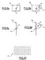
- On choisit des points caractéristiques qui peuvent être par exemple les points d'une
grille orthogonale 80 de points disposés régulièrement comme présenté sur lafigure 10 . - On calcule la différence 73 par exemple en effectuant la somme pour chaque point caractéristique des valeurs absolues des différences entre chaque nombre caractérisant la position corrigée, la couleur corrigée, l'intensité corrigée, la forme corrigée respectivement pour le point réel et pour le point mathématique. La fonction somme des valeurs absolues des différences peut être remplacée par une autre fonction comme la moyenne, la somme des carrés ou toute autre fonction permettant de combiner les nombres.
- We choose characteristic points which can be for example the points of an
orthogonal grid 80 of points arranged regularly as presented on thefigure 10 . - The
difference 73 is calculated, for example, by summing for each characteristic point the absolute values of the differences between each number characterizing the corrected position, the corrected color, the corrected intensity, the shape corrected respectively for the real point and for the mathematical point. . The sum function of the absolute values of the differences can be replaced by another function such as the mean, the sum of the squares or any other function allowing to combine the numbers.
On appelle scène de référence 9 une scène 3 dont certaines caractéristiques sont connues. A titre d'exemple, la
En se référant à la
En se référant à la
En se référant à la
On va maintenant décrire, en se référant à la
On définit la différence entre une image transformée 13 et une classe d'images de synthèse 7 comme la plus faible différence entre ladite image transformée 13 et l'une quelconque des images de synthèse 207 de ladite classe d'images de synthèse 7.The difference between a transformed
Ensuite, on va décrire, en se référant sur la
- Dans le cas d'une scène de référence 9 donnée associée à un jeu de caractéristiques utilisées 74 données, on choisit la transformation paramétrable 12 (et ses paramètres) qui permet de transformer l'image de référence 11 en l'image transformée 13 qui présente la plus faible différence avec la classe d'images de synthèse 7. La classe d'image de synthèse 7 et l'image transformée 13 sont alors dites proches. On appelle écart 14 ladite différence.
- Dans le cas d'un groupe de scènes de référence données associées à des jeux de caractéristiques utilisées 74 donnés, on choisit la transformation paramétrable 12 (et ses paramètres) en fonction des différences entre l'image transformée 13 de chaque scène de référence 9 et la classe d'images de synthèse 7 de chaque scène de référence 9 considérée. On choisit la transformation paramétrable 12 (et ses paramètres) qui permet de transformer les images de référence 11 en des images transformées 13 telle que la somme desdites différences soit la plus faible. La fonction somme peut être remplacée par une autre fonction comme le produit. La classe d'image de synthèse 7 et les images transformées 13 sont alors dites proches. On appelle écart 14 une valeur obtenue à partir desdites différences, par exemple en en calculant la moyenne.
- Dans le cas où certaines caractéristiques utilisées 74 sont inconnues, il est possible de les déterminer à partir de la capture de plusieurs images de référence 11 d'au moins une scène de référence 9. Dans ce cas, on détermine simultanément les caractéristiques inconnues et la transformation paramétrable 12 (et ses paramètres) qui permet de transformer les images de référence 11 en des images transformées 13 telles que la somme desdites différences soit la plus faible, notamment par calcul itératif ou par résolution d'équations concernant la somme desdites différences et/ou leur produit et/ou toute autre combinaison appropriée desdites différences. La classe d'image de synthèse 7 et les images transformées 13 sont alors dites proches. Les caractéristiques inconnues peuvent par exemple être les positions et les orientations relatives de la surface du capteur 110 et de chaque scène de référence 9 considérée. On appelle écart 14 une valeur obtenue à partir desdites différences, par exemple en en calculant la moyenne. Ensuite, on va décrire, en se référant sur la
figure 12 , un premier algorithme de calcul permettant de procéder à un choix :
- dans un ensemble de modèles de transformation paramétrables,
- dans un ensemble de modèles de transformation paramétrables inverses,
- dans un ensemble d'images de synthèse,
- dans un ensemble de scènes de référence et dans un ensemble d'images transformées.
- In the case of a given
reference scene 9 associated with a set of characteristics used 74 data, one chooses the parameterizable transformation 12 (and its parameters) which makes it possible to transform thereference image 11 into the transformedimage 13 which presents the smallest difference with the class ofcomputer images 7. The class of computer-generatedimage 7 and the transformedimage 13 are then said to be close. We callgap 14 said difference. - In the case of a group of given reference scenes associated with given sets of
characteristics 74, the parameterizable transformation 12 (and its parameters) is chosen as a function of the differences between the transformedimage 13 of eachreference scene 9 and the class ofcomputer images 7 of eachreference scene 9 considered. We choose the parameterizable transformation 12 (and its parameters) which makes it possible to transform thereference images 11 into transformedimages 13 such that the sum of said differences is the smallest. The sum function can be replaced by another function such as the product. Thesynthesis image class 7 and the transformedimages 13 are then said to be close. Thedifference 14 is a value obtained from said differences, for example by calculating the average thereof. - In the case where certain characteristics used 74 are unknown, it is possible to determine them from the capture of
several reference images 11 of at least onereference scene 9. In this case, the unknown characteristics and the parameterizable transformation 12 (and its parameters) which makes it possible to transform thereference images 11 into transformedimages 13 such that the sum of said differences is the smallest, in particular by calculation iteratively or by solving equations relating to the sum of said differences and / or their product and / or any other appropriate combination of said differences. Thesynthesis image class 7 and the transformedimages 13 are then said to be close. The unknown characteristics can for example be the relative positions and orientations of the surface of thesensor 110 and of eachreference scene 9 considered. Thedifference 14 is a value obtained from said differences, for example by calculating the average thereof. Then we will describe, referring to thefigure 12 , a first calculation algorithm making it possible to make a choice:
- in a set of parameterizable transformation models,
- in a set of inverse parameterizable transformation models,
- in a set of computer images,
- in a set of reference scenes and in a set of transformed images.
Ce choix porte sur :
- une scène de référence 9, et/ou
une image transformée 13, et/ou- un modèle de
transformation paramétrable 12 permettant de transformer l'image de référence 11, obtenue en capturant la scène de référence 9 au moyen de l'appareil de captured'image 1, en l'image transformée 13, et/ou - un modèle de
transformation paramétrable inverse 212 permettant de transformer l'image transformée 13 en l'image de référence 11, et/ou - une image de synthèse 207 obtenue à partir de la scène de référence 9 et/ou obtenue à partir de l'image de référence 11.
- a
reference scene 9, and / or - a transformed
image 13, and / or - a
parameterizable transformation model 12 making it possible to transform thereference image 11, obtained by capturing thereference scene 9 by means of the image-capture apparatus 1, in the transformedimage 13, and / or - an inverse
parameterizable transformation model 212 making it possible to transform the transformedimage 13 into thereference image 11, and / or - a
synthesis image 207 obtained from thereference scene 9 and / or obtained from thereference image 11.
Le choix retenu est celui qui minimise la différence entre l'image transformée 13 et l'image de synthèse 207. L'image de synthèse 207 et l'image transformée 13 sont alors dites proches. On appelle écart 14 ladite différence.The choice chosen is that which minimizes the difference between the transformed
De préférence, selon l'invention le premier algorithme de calcul permet de choisir dans un ensemble de projections mathématiques, une projection mathématique 8 permettant de réaliser l'image de synthèse 207 à partir de la scène de référence 9.Preferably, according to the invention, the first calculation algorithm makes it possible to choose, in a set of mathematical projections, a
Ensuite, on va décrire, en se référant sur la
- choisir au moins une scène de référence 9,
- capturer au moins une image de référence 11 de chaque scène de référence 9 au moyen de l'appareil de capture
d'image 1.
- choose at least one
reference scene 9, - capturing at least one
reference image 11 of eachreference scene 9 by means of theimage capture apparatus 1.
Ce second algorithme comporte en outre l'étape de choisir dans un ensemble de modèles de transformation paramétrables et dans un ensemble d'images de synthèse :
- un modèle de
transformation paramétrable 12 permettant de transformer l'image de référence 11, en uneimage transformée 13, et/ou - une image de synthèse 207 obtenue à partir de la scène de référence 9 et/ou obtenue à partir de l'image de référence 11,
- a
parameterizable transformation model 12 making it possible to transform thereference image 11 into a transformedimage 13, and / or - a
synthesis image 207 obtained from thereference scene 9 and / or obtained from thereference image 11,
Le choix retenu est celui qui minimise la différence entre l'image transformée 13 et l'image de synthèse 207. L'image de synthèse 207 et l'image transformée 13 sont alors dites proches. On appelle écart 14 ladite différence.The choice chosen is that which minimizes the difference between the transformed
De préférence, selon l'invention le second algorithme de calcul permet de choisir dans un ensemble de projections mathématiques, une projection mathématique 8 permettant de réaliser l'image de synthèse 207 à partir de la scène de référence 9.Preferably, according to the invention the second calculation algorithm makes it possible to choose from a set of mathematical projections, a
On appelle meilleure transformation :
- la transformation qui, parmi les modèles de
transformation paramétrables 12, permet de transformer chaque image de référence 11 enune image transformée 13 proche de la classe d'images de synthèse 7 de la scène de référence 9 correspondant à ladite image de référence 11, et/ou,
- le modèles de
transformation paramétrables 12 parmi les modèles de transformation paramétrables, telle que l'image transformée 13 soit proche de l'image de synthèse 207, et/ou - le modèles de
transformation paramétrables inverses 212 parmi les modèles de transformation paramétrables inverses, telle que l'image transformée 13 soit proche de l'image de synthèse 207.
- the transformation which, among the
parameterizable transformation models 12, makes it possible to transform eachreference image 11 in a transformedimage 13 close to thesynthesis image class 7 of thereference scene 9 corresponding to saidreference image 11, and / or,
- the
parameterizable transformation models 12 among the parameterizable transformation models, such that the transformedimage 13 is close to thesynthesis image 207, and / or - the inverse
parameterizable transformation models 212 among inverse parameterizable transformation models, such that the transformedimage 13 is close to thesynthesis image 207.
On appelle calibrage un procédé qui permet d'obtenir des données relatives aux caractéristiques intrinsèques de l'appareil de capture d'image 1, ce pour une ou plusieurs configurations utilisées constituées chacune d'une optique 100 associée à un appareil de capture d'image 1.Calibration is a process which makes it possible to obtain data relating to the intrinsic characteristics of the image-
Cas 1 : dans le cas où il n'y a qu'une configuration, ledit procédé comprend les étapes suivantes :
- l'étape de monter ladite optique 100 sur ledit appareil de capture
d'image 1, - l'étape de choisir une ou plusieurs scènes de référence 9,
- l'étape de choisir plusieurs caractéristiques utilisées 74,
- l'étape de capturer des image desdites scènes de référence 9 pour lesdites caractéristiques utilisées,
- l'étape de calculer la meilleure transformation pour chaque groupe de scènes de référence 9 correspondant aux mêmes caractéristiques utilisées 74.
- the step of mounting said
optics 100 on saidimage capture apparatus 1, - the step of choosing one or
more reference scenes 9, - the stage of choosing several characteristics used 74,
- the step of capturing images of said
reference scenes 9 for said characteristics used, - the step of calculating the best transformation for each group of
reference scenes 9 corresponding to the same characteristics used 74.
Cas 2 : dans le cas où on considère toutes les configurations correspondant à un appareil de capture d'image 1 donné et à toutes les optiques 100 d'un même type, ledit procédé comprend les étapes suivantes :
- l'étape de choisir une ou plusieurs scènes de référence 9,
- l'étape de choisir plusieurs caractéristiques utilisées 74,
- l'étape de calculer des
images 103 à partir des caractéristiques utilisées 74 et notamment des formules de l'optique 100 de la configuration utilisée et des valeurs de paramètres, ce par exemple à l'aide d'un logiciel de calcul d'optique par tracé de rayons, - l'étape de calculer la meilleure transformation pour chaque groupe de scènes de référence 9 correspondant aux mêmes caractéristiques utilisées.
- the step of choosing one or
more reference scenes 9, - the stage of choosing several characteristics used 74,
- the step of calculating
images 103 from the characteristics used 74 and in particular from the formulas of theoptics 100 of the configuration used and the values of parameters, for example using optical calculation software by ray pattern, - the step of calculating the best transformation for each group of
reference scenes 9 corresponding to the same characteristics used.
Cas 3 : dans le cas où on considère toutes les configurations correspondant à une optique 100 donnée et à tous les appareils de capture d'image 1 d'un même type, ledit procédé comprend les étapes suivantes :
- l'étape de monter ladite optique 100 sur un appareil de capture
d'image 1 du type considéré, - l'étape de choisir une ou plusieurs scènes de référence 9,
- l'étape de choisir plusieurs caractéristiques utilisées 74,
- l'étape de capturer des images desdites scènes de référence 9 pour lesdites caractéristiques utilisées,
- l'étape de calculer la meilleure transformation pour chaque groupe de scènes de référence 9 correspondant aux mêmes caractéristiques utilisées.
- the step of mounting said
optics 100 on animage capture apparatus 1 of the type considered, - the step of choosing one or
more reference scenes 9, - the stage of choosing several characteristics used 74,
- the step of capturing images of said
reference scenes 9 for said characteristics used, - the step of calculating the best transformation for each group of
reference scenes 9 corresponding to the same characteristics used.
Le calibrage peut être effectué, de manière préférentielle, par le constructeur de l'appareil de capture d'image 1, ce pour chaque appareil et configuration dans le cas 1. Cette méthode est plus précise mais plus contraignante et bien adaptée dans le cas ou l'optique 100 n'est pas interchangeable.Calibration can be carried out, preferably, by the manufacturer of the
Le calibrage peut alternativement être effectué par le constructeur de l'appareil de capture d'image 1, ce pour chaque type et configuration d'appareil dans le cas 2. Cette méthode est moins précise mais plus simple.The calibration may alternatively be performed by the manufacturer of the
Le calibrage peut alternativement être effectué par le constructeur de l'appareil de capture d'image 1 ou un tiers, ce pour chaque optique 100 et type d'appareil dans la cas 3. Cette méthode est un compromis permettant d'utiliser une optique 100 sur tous les appareils de capture d'image 1 d'un type sans refaire le calibrage pour chaque combinaison d'appareil de capture d'image 1 et d'optique 100. Dans le cas d'un appareil de capture d'image à optique non interchangeable, la méthode permet de ne faire le calibrage qu'une fois pour un type d'appareil donné.The calibration may alternatively be performed by the manufacturer of the
Le calibrage peut alternativement être effectué par le revendeur ou installateur de l'appareil, ce pour chaque appareil de capture d'image 1 et configuration dans le cas 1.Calibration can alternatively be performed by the dealer or installer of the device, for each
Le calibrage peut alternativement être effectué par le revendeur ou installateur de l'appareil, ce pour chaque optique 100 et type d'appareil dans le cas 3.Calibration can alternatively be performed by the dealer or installer of the device, for each optical 100 and type of device in
Le calibrage peut alternativement être effectué par l'utilisateur de l'appareil, ce pour chaque appareil et configuration dans le cas 1.Calibration can alternatively be performed by the user of the device for each device and configuration in
Le calibrage peut alternativement être effectué par l'utilisateur de l'appareil, ce pour chaque optique 100 et type d'appareil dans le cas 3.Calibration can alternatively be performed by the user of the device, for each optical 100 and type of device in
On appelle conception d'optique numérique, un procédé pour diminuer le coût de l'optique 100, consistant à :
- concevoir ou choisir dans un
catalogue une optique 100 ayant des défauts, notamment de positionnement des points réels, - diminuer le nombre de lentilles, et/ou
- simplifier la forme des lentilles, et/ou
- utiliser des matériaux, traitements ou procédés de fabrication moins coûteux.
- designing or choosing from a catalog an
optics 100 having defects, in particular for positioning the real points, - decrease the number of lenses, and / or
- simplify the shape of the lenses, and / or
- use less expensive materials, processes or manufacturing processes.
Ledit procédé comprend les étapes suivantes :
- l'étape de choisir une différence (au sens ci-dessus défini) acceptable,
- l'étape de choisir une ou plusieurs scènes de référence 9,
- l'étape de choisir plusieurs caractéristiques utilisées 74.
- the step of choosing a difference (in the sense defined above) acceptable,
- the step of choosing one or
more reference scenes 9, - the stage of choosing several characteristics used 74.
Ledit procédé comprend en outre l'itération des étapes suivantes :
- l'étape de choisir une formule optique comprenant notamment la forme, le matériau et la disposition des lentilles,
- l'étape de calculer des
images 103 à partir des caractéristiques utilisées 74 et notamment des formules de l'optique 100 de la configuration utilisée, en mettant en oeuvre, par exemple, un logiciel de calcul d'optique par tracé de rayons, ou en effectuant des mesures sur un prototype, - l'étape de calculer la meilleure transformation pour chaque groupe de scènes de référence 9 correspondant aux mêmes caractéristiques utilisées 74,
- l'étape de vérifier si la différence est acceptable, jusqu'à ce que la différence soit acceptable.
- the step of choosing an optical formula comprising in particular the shape, the material and the disposition of the lenses,
- the step of calculating
images 103 from the characteristics used 74 and in particular from the formulas of theoptics 100 of the configuration used, by implementing, for example, ray tracing optical calculation software, or performing measurements on a prototype, - the step of calculating the best transformation for each group of
reference scenes 9 corresponding to the same characteristics used 74, - the step of checking whether the difference is acceptable, until the difference is acceptable.
On appelle informations formatées 15 associées à l'image 103 ou informations formatées 15, tout ou partie des données suivantes :
- des données relatives aux caractéristiques techniques intrinsèques de l'appareil de capture
d'image 1, notamment les caractéristiques de distorsion, et/ou - des données relatives aux caractéristiques techniques de l'appareil de capture
d'image 1 au moment de la capture d'image, notamment le temps de pose, et/ou - des données relatives aux préférences dudit utilisateur, notamment la température de couleurs, et/ou
- des données relatives aux écarts 14.
- data relating to the intrinsic technical characteristics of the
image capture apparatus 1, including the distortion characteristics, and / or - data relating to the technical characteristics of the
image capture apparatus 1 at the time of the image capture, in particular the exposure time, and / or - data relating to the preferences of said user, in particular the color temperature, and / or
discrepancy data 14.
On appelle base de données de caractéristiques 22, une base de données comprenant, pour un ou plusieurs appareils de capture d'image 1 et pour une ou plusieurs images 103, des informations formatées 15.
Ladite base de donnée de caractéristiques 22 peut être stockée de manière centralisée ou répartie, et peut être notamment :
- intégrée dans l'appareil de capture
d'image 1, - intégrée dans l'optique 100,
- intégrée sur un dispositif de stockage amovible,
- intégrée dans un PC ou autre ordinateur relié aux autres éléments pendant la capture d'image,
- intégrée dans un PC ou autre ordinateur relié aux autres éléments après la capture d'image,
- intégrée dans un PC ou autre ordinateur capable de lire un support de stockage commun avec l'appareil de capture
d'image 1, - intégrée dans un serveur distant relié à un PC ou autre ordinateur lui même relié aux autre éléments de la capture d'image.
- embedded in the
image capture apparatus 1, - integrated in
optics 100, - integrated on a removable storage device,
- embedded in a PC or other computer connected to other elements during image capture,
- integrated in a PC or other computer connected to other elements after image capture,
- integrated into a PC or other computer capable of reading a common storage medium with the
image capture apparatus 1, - embedded in a remote server connected to a PC or other computer itself connected to the other elements of the image capture.
On va maintenant définir la notion de champs 91 en se référant à la
- (a) la distance focale,
- (b) la profondeur de champ,
- (c) les défauts géométriques.
- (a) the focal length,
- (b) the depth of field,
- (c) geometric defects.
Lesdits défauts géométriques comprennent les défauts de géométrie de l'image 103 caractérisés par les paramètres associés aux caractéristiques de la prise de vue 74 et une transformation paramétrable représentant les caractéristiques de l'appareil de capture d'image 1 au moment de la prise de vue. Lesdits paramètres et ladite transformation paramétrable permettent de calculer la position corrigée d'un point de l'image 103.Said geometric defects include the
Lesdits défauts géométriques comprennent en outre le vignetage caractérisé par les paramètres associés aux caractéristiques de la prise de vue 74 et une transformation paramétrable représentant les caractéristiques de l'appareil de capture d'image 1 au moment de la prise de vue. Lesdits paramètres et ladite transformation paramétrable permettent de calculer l'intensité corrigée d'un point de l'image 103.Said geometrical defects also comprise the vignetting characterized by the parameters associated with the characteristics of the
Lesdits défauts géométriques comprennent en outre la dominante colorée caractérisée par les paramètres associés aux caractéristiques de la prise de vue 74 et une transformation paramétrable représentant les caractéristiques de l'appareil de capture d'image 1 au moment de la prise de vue. Lesdits paramètres et ladite transformation paramétrable permettent de calculer la couleur corrigée d'un point de l'image 103.Said geometrical defects furthermore comprise the colored dominant characterized by the parameters associated with the characteristics of the
Lesdits champs 91 comprennent en outre (d) le piqué de l'image 103.Said
Ledit piqué comprend le flou de résolution de l'image 103 caractérisé par les paramètres associés aux caractéristiques de la prise de vue 74 et une transformation paramétrable représentant les caractéristiques de l'appareil de capture d'image 1 au moment de la prise de vue. Lesdits paramètres et ladite transformation paramétrable permettent de calculer la forme corrigée d'un point de l'image 103. Le flou couvre en particulier le coma, l'aberration sphérique, l'astigmatisme, le regroupement en pixels 104, l'aberration chromatique, la profondeur de champ, la diffraction, les réflexions parasites, la courbure de champ.Said sharpness comprises the
Ledit piqué comprend en outre le flou de profondeur de champ, notamment les aberrations sphériques, le coma, l'astigmatisme. Ledit flou dépend de la distance des points de la scène 3 par rapport à l'appareil de capture d'image 1 et est caractérisé par les paramètres associés aux caractéristiques de la prise de vue 74 et une transformation paramétrable représentant les caractéristiques de l'appareil de capture d'image 1 au moment de la prise de vue. Lesdits paramètres et ladite transformation paramétrable permettent de calculer la forme corrigée d'un point de l'image 103.Said dive further includes the depth of field blur, including spherical aberrations, coma, astigmatism. Said blur depends on the distance of the points of the
Lesdits champs 91 comprennent en outre (e) des paramètres de la méthode de quantification. Lesdits paramètres dépendent de la géométrie et la physique du capteur 101, de l'architecture de l'électronique 102 et d'éventuels logiciels de traitement.Said
Lesdits paramètres comprennent une fonction représentant les variations de l'intensité d'un pixel 104 en fonction de la longueur d'onde et du flux lumineux provenant de ladite scène 3. Ladite fonction comprend notamment les information de gamma.Said parameters comprise a function representing the variations of the intensity of a pixel 104 as a function of the wavelength and the luminous flux originating from said
Lesdits paramètres comprennent en outre :
- la géométrie dudit capteur 101, notamment la forme, la position relative et le nombre des éléments sensibles dudit capteur 101,
- une fonction représentant la distribution spatiale et temporelle du bruit de l'appareil de capture
d'image 1, - une valeur représentant le temps de pose de la capture d'image.
- the geometry of said
sensor 101, in particular the shape, the relative position and the number of the sensitive elements of saidsensor 101, - a function representing the spatial and temporal distribution of the noise of the
image capture apparatus 1, - a value representing the exposure time of the image capture.
Lesdits champs 91 comprennent en outre (f) des paramètres des traitements numériques effectués par l'appareil de capture d'image 1, notamment le zoom numérique, la compression. Ces paramètres dépendent du logiciel de traitement de l'appareil de capture d'image 1 et des réglages de l'utilisateur.The said fields 91 furthermore comprise (f) parameters of the digital processing carried out by the image-
Lesdits champs 91 comprennent en outre :
- (g) des paramètres représentant les préférences de l'utilisateur, notamment en ce qui concerne le degré de flou, la résolution de l'image 103.
- (h) les écarts 14.
- (g) parameters representing the preferences of the user, particularly with regard to the degree of blur, the resolution of the
image 103. - (h)
differences 14.
Les informations formatées 15 peuvent être calculées et enregistrées dans la base de données 22 en plusieurs étapes.
- a) Une étape à l'issue de la conception de l'appareil de capture
d'image 1.
Cette étape permet d'obtenir des caractéristiques techniques intrinsèques de l'appareil de captured'image 1, et notamment :- la distribution spatiale et temporelle du bruit généré
par l'électronique 102, - la loi de conversion flux lumineux en valeur de pixel,
- la géométrie du capteur 101.
- la distribution spatiale et temporelle du bruit généré
- b) Une étape à l'issue du calibrage ou conception d'optique numérique.
Cette étape permet d'obtenir d'autres caractéristiques techniques intrinsèques de l'appareil de captured'image 1, et notamment, pour un certain nombre de valeurs de caractéristiques utilisées, la meilleure transformation associée et l'écart 14 associé. - c) Une étape de choix des préférences de l'utilisateur à l'aide de boutons, menus ou support amovible ou connexion à un autre dispositif.
- d) Une étape de capture d'image.
- a) A step after the design of the
image capture device 1.
This step makes it possible to obtain intrinsic technical characteristics of theimage capture apparatus 1, and in particular:- the spatial and temporal distribution of the noise generated by the
electronics 102, - the law of conversion luminous flux in value of pixel,
- the geometry of the
sensor 101.
- the spatial and temporal distribution of the noise generated by the
- b) A step after calibration or digital optical design.
This step makes it possible to obtain other intrinsic technical characteristics of theimage capture apparatus 1, and in particular, for a certain number of characteristic values used, the best associated transformation and the associateddifference 14. - c) A step of choosing the preferences of the user using buttons, menus or removable media or connection to another device.
- d) An image capture step.
Cette étape (d) permet d'obtenir des caractéristiques techniques de l'appareil de capture d'image 1 au moment de la capture d'image, et notamment le temps de pose, déterminé par les réglages manuels ou automatiques effectués.This step (d) makes it possible to obtain technical characteristics of the image-
L'étape (d) permet en outre d'obtenir la distance focale. La distance focale est calculée à partir :
- d'une mesure de la position du groupe de lentilles de focale variable de l'optique 100 de la configuration utilisée, ou
- d'une consigne donnée au moteur de positionnement, ou
- d'une donnée constructeur si la focale est fixe.
- a measurement of the position of the group of lenses of variable focal length of the
optics 100 of the configuration used, or - a given instruction to the positioning motor, or
- a manufacturer's data if the focal length is fixed.
Ladite distance focale peut enfin être déterminée par l'analyse du contenu de l'image 103.Said focal distance can finally be determined by analyzing the content of the
L'étape (d) permet en outre d'obtenir la profondeur de champ. La profondeur de champ est calculée à partir :
- d'une mesure de la position du groupe de lentilles de focalisation de l'optique 100 de la configuration utilisée, ou
- d'une consigne donnée au moteur de positionnement, ou
- d'une donnée constructeur si la profondeur de champ est fixe.
- a measurement of the position of the focus lens group of the
optics 100 of the configuration used, or - a given instruction to the positioning motor, or
- a constructor data if the depth of field is fixed.
L'étape (d) permet en outre d'obtenir les défauts de géométrie et de piqué. Les défauts de géométrie et de piqué correspondent à une transformation calculée à l'aide d'une combinaison des transformations de la base de données de caractéristiques 22 obtenues à l'issue de l'étape (b). Cette combinaison est choisie pour représenter les valeurs de paramètres correspondant aux caractéristiques utilisées 74, notamment la distance focale.Step (d) also makes it possible to obtain geometry and sharpness defects. The geometry and sharpness defects correspond to a transformation calculated using a combination of the transformations of the
L'étape (d) permet en outre d'obtenir les paramètres de traitement numériques effectués par l'appareil de capture d'image 1. Ces paramètres sont déterminés par les réglages manuels ou automatiques effectués.Step (d) further provides the digital processing parameters performed by the
Le calcul des informations formatées 15 selon les étapes (a) à (d) peut être réalisé par :
- un dispositif ou logiciel intégré à l'appareil de capture
d'image 1, et/ou - un logiciel pilote dans un PC ou autre ordinateur, et/ou
- un logiciel dans un PC ou autre ordinateur, et/ou
- une combinaison des trois.
- a device or software integrated in the
image capture apparatus 1, and / or - a driver software in a PC or other computer, and / or
- software in a PC or other computer, and / or
- a combination of the three.
Les transformations ci-dessus mentionnées à l'étape (b) et à l'étape (d) peuvent être stockées sous la forme :
- d'une formule mathématique générale,
- d'une formule mathématique pour chaque point,
- d'une formule mathématique pour certains points caractéristiques.
- of a general mathematical formula,
- a mathematical formula for each point,
- a mathematical formula for some characteristic points.
Les formules mathématiques peuvent être décrites par :
- une liste de coefficients,
- une liste de coefficients et de coordonnées.
- a list of coefficients,
- a list of coefficients and coordinates.
Ces différentes méthodes permettent de faire un compromis entre la taille de la mémoire disponible pour stocker les formules et la puissance de calcul disponible pour calculer les images corrigées 71.These different methods make it possible to make a compromise between the size of the memory available for storing the formulas and the computing power available to calculate the corrected
En outre, afin de retrouver les données, des identifiants associés aux données sont enregistrés dans la base de données 22. Ces identifiants comprennent notamment :
- un identifiant du type et de la référence de l'appareil de capture
d'image 1, - un identifiant du type et de la référence de l'optique 100 si elle est amovible,
- un identifiant du type et de la référence de tout autre elément amovible ayant un lien avec les informations stockées,
- un identifiant de l'image 103,
- un identifiant de l'information formatée 15.
- an identifier of the type and reference of the
image capture apparatus 1, - an identifier of the type and the reference of
optics 100 if it is removable, - an identifier of the type and the reference of any other removable element having a link with the stored information,
- an identifier of the
image 103, - an identifier of the formatted
information 15.
Comme décrit par la
L'image complétée 120 peut être calculée par l'appareil de capture d'image 1. Elle peut être également calculée par un dispositif de calcul externe, par exemple un ordinateur.The completed
On appelle logiciel de traitement d'image 4, un logiciel qui prend en entrée une ou plusieurs images complétées 120 et qui effectue des traitements sur ces images. Ces traitements peuvent comprendre, notamment :
- de calculer d'une
image corrigée 71, - d'effectuer des mesures dans le monde réel,
- de combiner plusieurs images,
- d'améliorer la fidélité des images par rapport au monde réel,
- d'améliorer la qualité subjective des images,
- de détecter des objets ou personnes 107 dans une
scène 3, - d'ajouter des objets ou personnes 107 dans une
scène 3, - de remplacer ou modifier des objets ou personnes 107 dans une
scène 3, - de retirer les ombres d'une
scène 3, - d'ajouter des ombres dans une scène 3,
- de rechercher des objets dans une base d'images. Ledit logiciel de traitement d'image peut être :
- intégré à l'appareil de capture
d'image 1, - exécuté sur des moyens de calcul 17 reliés à l'appareil de capture
d'image 1 par des moyens detransmission 18.
- to calculate a corrected
image 71, - to perform measurements in the real world,
- to combine several images,
- to improve the fidelity of images in relation to the real world,
- to improve the subjective quality of the images,
- to detect objects or
people 107 in ascene 3, - to add objects or
people 107 in ascene 3, - to replace or modify objects or
people 107 in ascene 3, - to remove the shadows of a
scene 3, - to add shadows in a
scene 3, - to search for objects in an image database. Said image processing software can be:
- embedded in the
image capture device 1, - executed on calculation means 17 connected to the image-
capture apparatus 1 by transmission means 18.
On appelle optique numérique, la combinaison d'un appareil de capture d'image 1, d'une base de données de caractéristiques 22 et d'un moyen de calcul 17 permettant :
- la capture
d'image d'une image 103, - le calcul de l'image complétée,
- le calcul de l'image corrigée 71.
- the image capture of an
image 103, - the calculation of the completed image,
- the calculation of the corrected
image 71.
De manière préférentielle, l'utilisateur obtient directement l'image corrigée 71. S'il le souhaite, l'utilisateur peut demander la suppression de la correction automatique.Preferably, the user directly obtains the corrected
La base de données de caractéristiques 22 peut être :
- intégrée dans l'appareil de capture
d'image 1, - intégrée dans un PC ou autre ordinateur relié aux autres éléments pendant la capture d'image,
- intégrée dans un PC ou autre ordinateur relié aux autres éléments après la capture d'image,
- intégrée dans un PC ou autre ordinateur capable de lire un support de stockage commun avec l'appareil de capture
d'image 1, - intégrée dans un serveur distant relié à un PC ou autre ordinateur lui même relié aux autre éléments de la capture d'image.
- embedded in the
image capture apparatus 1, - embedded in a PC or other computer connected to other elements during image capture,
- integrated in a PC or other computer connected to other elements after image capture,
- integrated into a PC or other computer capable of reading a common storage medium with the
image capture apparatus 1, - embedded in a remote server connected to a PC or other computer itself connected to the other elements of the image capture.
Le moyen de calcul 17 peut être :
- intégré sur un composant avec le capteur 101,
- intégré sur un composant avec une partie de l'électronique 102,
- intégré dans l'appareil de capture
d'image 1, - intégré dans un PC ou autre ordinateur relié aux autres éléments pendant la capture d'image,
- intégré dans un PC ou autre ordinateur relié aux autres éléments après la capture d'image,
- intégré dans un PC ou autre ordinateur capable de lire un support de stockage commun avec l'appareil de capture
d'image 1, - intégré dans un serveur distant relié à un PC ou autre ordinateur lui même relié aux autres éléments de la capture d'image.
- integrated on a component with the
sensor 101, - integrated on a component with a part of the
electronics 102, - embedded in the
image capture apparatus 1, - embedded in a PC or other computer connected to other elements during image capture,
- embedded in a PC or other computer connected to other elements after image capture,
- integrated into a PC or other computer capable of reading a common storage medium with the
image capture apparatus 1, - embedded in a remote server connected to a PC or other computer itself connected to the other elements of the image capture.
Dans les précédents paragraphes, on a essentiellement précisé les concepts et la description du procédé et du système selon l'invention pour fournir à des logiciels de traitement d'images 4 des informations formatées 15 liées aux caractéristiques des appareils de capture d'image 1.In the preceding paragraphs, the concepts and the description of the method and system according to the invention have essentially been clarified to provide
Dans les paragraphes qui suivent, on va élargir la définition des concepts et compléter la description du procédé et du système selon l'invention pour fournir à des logiciels de traitement d'images 4 des informations formatées 15 liées aux caractéristiques des moyens de restitution d'image 19. On aura ainsi exposé le traitement d'une chaîne complète.In the following paragraphs, the definition of the concepts will be expanded and the description of the method and the system according to the invention will be added to provide
Le traitement de la chaîne complète permet :
- d'améliorer la qualité de l'image 103 d'un bout à l'autre de la chaîne, pour obtenir une
image restituée 191 corrigeant les défauts de l'appareil de captured'image 1 et du moyen derestitution d'image 19, et/ou - d'utiliser des optiques de moindre qualité et de moindre coût dans un projecteur vidéo en combinaison avec un logiciel d'amélioration de la qualité des images.
- to improve the quality of the
image 103 from one end of the chain to the other, to obtain a restoredimage 191 correcting the defects of theimage capture apparatus 1 and the image recovery means 19 , and or - to use lower quality and lower cost optics in a video projector in combination with image quality enhancement software.
En s'appuyant sur les
Les compléments ou modifications à apporter aux définitions dans le cas d'un moyen de restitution d'image 19 peuvent être extrapolées mutatis mutandis par un homme de métier à partir des définitions fournies dans le cas d'un appareil de capture d'image 1. Toutefois, afin d'illustrer cette méthode, on va maintenant décrire en se référant notamment à la
On désigne par caractéristiques de restitution utilisées 95 les caractéristiques intrinsèques des moyens de restitution d'image 19, les caractéristiques du moyen de restitution d'image 19 au moment de la restitution d'image, et les préférences de l'utilisateur au moment de la restitution des images. Notamment dans le cas d'un projecteur, les caractéristiques de restitution utilisées 95 comprennent la forme et la position de l'écran utilisé.By rendering characteristics used, the intrinsic characteristics of the image-reproduction means 19, the characteristics of the image-rendering means 19 at the time of the image rendering, and the preferences of the user at the time of the reproduction are denoted by the rendering characteristics used. restitution of the images. Especially in the case of a projector, the rendering characteristics used 95 include the shape and position of the screen used.
On désigne par modèle de transformation paramétrable de restitution 97 (ou de manière condensée, transformation paramétrable de restitution 97),une transformation mathématique similaire au modèle de transformation paramétrable 12. On désigne par modèle de transformation paramétrable de restitution inverse 297 (ou de manière condensée, transformation paramétrable de restitution inverse 297),une transformation mathématique similaire au modèle de transformation paramétrable inverse 212.The expression parameterizable transformation model 97 (or condensed, parameterizable restitution transformation 97) denotes a mathematical transformation similar to the
On désigne par image corrigée de restitution 94 l'image obtenue par application de la transformation paramétrable de restitution 97 à l'image 103.The corrected
On désigne par projection mathématique de restitution 96 une projection mathématique qui associe à une image corrigée de restitution 94, une image mathématique de restitution 92 sur la surface mathématique de restitution géométriquement associée à la surface du support de restitution 190. Les points mathématiques de restitution de la surface mathématique de restitution ont une forme, position, couleur et intensité calculées à partir de l'image corrigée de restitution 94.Referring to
On désigne par projection réelle de restitution 90 une projection associant à une image 103 une image restituée 191. Les valeurs de pixels de l'image 103 sont converties par l'électronique des moyens de restitution 19 en un signal qui pilote le modulateur des moyens de restitution 19. On obtient des points réels de restitution sur le support de restitution 190. Lesdits points réels de restitution sont dotés d'une forme, couleur, intensité et position. Le phénomène de regroupement en pixels 104 précédemment décrit dans le cas d'un appareil de capture d'image 1 ne se produit pas dans le cas d'un moyen de restitution d'image. En revanche, un phénomène inverse se produit qui fait notamment apparaître des droites comme des marches d'escalier.
On désigne par différence de restitution 93 la différence entre l'image restituée 191 et l'image mathématique de restitution 92. Cette différence de restitution 93 est obtenue mutatis mutandis comme la différence 73.The difference between the restored
On désigne par référence de restitution 209 une image 103 dont les valeurs des pixels 104 sont connues. On désigne par référence restituée 211, l'image restituée 191 obtenue par la projection mathématique de restitution 90 de la référence de restitution 209. On désigne par image de référence corrigée de restitution 213, l'image corrigée de restitution 94 correspondant à la référence de restitution 209, pour le modèle de transformation paramétrable de restitution 97 et/ou pour le modèle de transformation paramétrable de restitution inverse 297. On désigne par image de synthèse de restitution 307 l'image mathématique de restitution 92 obtenue par la projection mathématique de restitution 96 de l'image de référence corrigée de restitution 213.Referring
On désigne par meilleure transformation de restitution :
- pour une référence de
restitution 209 et des caractéristiques utilisées derestitution 95, celle qui permet detransformer l'image 103 en une image corrigée derestitution 94 telle que sa projection mathématique derestitution 92, présente la plus faible différence derestitution 93 avec l'image restituée 191, et/ou - la transformation paramétrable de
restitution 97 parmi les modèles de transformation paramétrables de restitution , telle que référence restituée 211 présente la plus faible différence derestitution 93 avec l'image de synthèse derestitution 307, et/ou - la transformation paramétrable de
restitution inverse 297 parmi les modèles de transformation paramétrables inverses, telle que référence restituée 211 présente la plus faible différence derestitution 93 avec l'image de synthèse derestitution 307.
- for a
restitution reference 209 and used restitution features 95, that which makes it possible to transform theimage 103 into a correctedrestitution image 94 such that itsmathematical restitution projection 92 has thesmallest restitution difference 93 with the renderedimage 191, and / or - the
parameterizable rendering transformation 97 among the parameterizable rendering transformation models, such as returnedreference 211, has thesmallest rendition difference 93 with the renderingsynthetic image 307, and / or - the parameterizable
reverse reproduction transformation 297 among inverse parameterizable transformation models, such as returnedreference 211, has thesmallest rendition difference 93 with therendering synthesis image 307.
La référence restituée 211 et l'image de synthèse de restitution 307 sont alors dites proches.The restored
Les procédés de calibrage de restitution et de conception d'optique numérique de restitution sont comparables aux procédés de calibrage et de conception d'optique numérique dans le cas d'un appareil de capture d'image 1. Certaines étapes comportent cependant des différences, et notamment les étapes suivantes :
- l'étape de choisir une référence de
restitution 209; - l'étape d'effectuer la restitution de ladite référence de restitution ;
- l'étape de calculer la meilleure transformation de restitution.
- the step of choosing a
restitution reference 209; - the step of performing the restitution of said restitution reference;
- the step of calculating the best rendition transformation.
De préférence, selon l'invention, le procédé comprend un sixième algorithme de calcul des informations formatées 15. Ce sixième algorithme permet d'effectuer un choix :
- dans un ensemble de modèles de transformation paramétrables de restitution,
- dans un ensemble de modèles de transformation paramétrables de restitution inverses,
- dans un ensemble de projections mathématiques de restitution,
- dans un ensemble de références de restitution et dans un ensemble d'images de référence corrigées de restitution.
- in a set of parameterizable transformation models of restitution,
- in a set of transformable transformation models of inverse reproduction,
- in a set of mathematical projections of restitution,
- in a set of restitution references and in a set of corrected reference images of restitution.
Le choix effectué par ce sixième algorithme porte sur :
- une référence de
restitution 209, et/ou - une image de référence corrigée de
restitution 213, et/ou - un modèle de transformation paramétrable de
restitution 97 permettant de transformer la référence derestitution 209 en l'image de référence corrigée derestitution 213, et/ou - un modèle de transformation paramétrable de
restitution inverse 297 permettant de transformer l'image de référence corrigée derestitution 213 en la référence derestitution 209, et/ou - une projection mathématique de
restitution 96 permettant de réaliser une image de synthèse derestitution 307 à partir de l'image de référence corrigée derestitution 213.
- a
restitution reference 209, and / or - a corrected reference image of
restitution 213, and / or - a parameterizable
restitution transformation model 97 making it possible to transform therestitution reference 209 into the correctedrestitution reference image 213, and / or - a parameterizable inverse
rendering transformation model 297 making it possible to transform the correctedrestitution reference image 213 into therestitution reference 209, and / or - a
mathematical rendering projection 96 making it possible to produce arendering synthesis image 307 from the correctedreference restitution image 213.
Le choix est effectué par ce sixième algorithme de telle sorte que l'image de synthèse de restitution 307 soit proche de la référence restituée 211 obtenue par restitution de la référence de restitution 209, au moyen du moyen de restitution d'images 19. La référence restituée 211 présente un écart de restitution 214 avec l'image de synthèse de restitution 307.The choice is made by this sixth algorithm so that the
Selon une variante de réalisation de l'invention, le procédé comprend un septième algorithme de calcul des informations formatées. Ce septième algorithme comporte les étapes de :
- choisir au moins une référence de
restitution 209, - restituer la référence de
restitution 209, au moyen du moyen derestitution d'images 19, en une référence restituée 211.
- choose at least one
restitution reference 209, - to restore the
restitution reference 209, by means of the image restitution means 19, to a restoredreference 211.
Ce septième algorithme permet également de choisir dans un ensemble de modèles de transformation paramétrables de restitution et dans un ensemble de projections mathématiques de restitution :
- un modèle de transformation paramétrable de
restitution 97 permettant de transformer la référence derestitution 209 en une image de référence corrigée derestitution 213, et - une projection mathématique de
restitution 96 permettant de réaliser une image de synthèse derestitution 307 à partir de l'image de référence corrigée derestitution 213.
- a parameterizable
restitution transformation model 97 making it possible to transform therestitution reference 209 into a correctedrestitution reference image 213, and - a
mathematical rendering projection 96 making it possible to produce arendering synthesis image 307 from the correctedreference restitution image 213.
Le choix est effectué par le septième algorithme de telle sorte que l'image de synthèse de restitution 307 soit proche de la référence restituée 211. La référence restituée présente un écart de restitution 214 avec l'image de synthèse de restitution 307. Le modèle de transformation paramétrable de restitution inverse 297 permet de transformer l'image de référence corrigée de restitution 213 en la référence de restitution 209.The choice is made by the seventh algorithm so that the
Selon une autre variante de réalisation l'invention, le procédé comprend un huitième algorithme de calcul des informations formatées. Ce huitième algorithme comporte l'étape de choisir une image de référence corrigée de restitution 213. Ce huitième algorithme comporte en outre l'étape d'effectuer un choix dans un ensemble de modèles de transformation paramétrables de restitution, dans un ensemble de projections mathématiques de restitution, dans un ensemble de références de restitution. Ce choix porte sur :
- une référence de
restitution 209, et/ou - un modèle de transformation paramétrable de
restitution 97 permettant de transformer la référence derestitution 209 en l'image de référence corrigée derestitution 213, et/ou
- un modèle de transformation paramétrable de
restitution inverse 297 permettant de transformer l'image de référence corrigée derestitution 213 en la référence derestitution 209, et/ou - une projection mathématique de
restitution 96 permettant de réaliser une image de synthèse derestitution 307 à partir de l'image de référence corrigée derestitution 213.
- a
restitution reference 209, and / or - a parameterizable transformation model of
restitution 97 making it possible to transform the reference ofrestitution 209 in the corrected reference image ofrestitution 213, and / or
- a parameterizable inverse
rendering transformation model 297 making it possible to transform the correctedrestitution reference image 213 into therestitution reference 209, and / or - a
mathematical rendering projection 96 making it possible to produce arendering synthesis image 307 from the correctedreference restitution image 213.
Le huitième algorithme effectue ce choix de telle sorte que l'image de synthèse de restitution 307 soit proche de la référence restituée 211 obtenue par restitution de la référence de restitution 209, au moyen du moyen de restitution d'images 19. La référence restituée 211 présente un écart de restitution avec l'image de synthèse de restitution 307.The eighth algorithm makes this choice so that the
De préférence, selon l'invention, le procédé comprend un neuvième algorithme de calcul des écarts de restitution 214. Ce neuvième algorithme comporte les étapes de :
- calculer les écarts de
restitution 214 entre la référence restituée 211 et l'image de synthèse derestitution 307, - associer les écarts de
restitution 214 aux informations formatées 15.
- calculating the
restitution variances 214 between the restoredreference 211 and therestitution synthesis image 307, - associating the
restitution variances 214 with the formattedinformation 15.
Il résulte de la combinaison des traits techniques qu'il est possible de vérifier automatiquement, par exemple pendant la fabrication de l'appareil que le procédé a produit des informations formatées dans des tolérances acceptables.As a result of the combination of technical features it is possible to check automatically, for example during manufacture of the apparatus that the process has produced information formatted within acceptable tolerances.
Les informations formatées 15 liées à un appareil de capture d'image 1 et celles liées à un moyen de restitution d'image 19 peuvent être mises bout à bout pour une même image.The formatted information related to an
Il est également possible de combiner les informations formatées 15 relatives à chacun des appareils, pour obtenir les informations formatées 15 relative à la chaîne d'appareils, par exemple par addition d'un champ de vecteur, dans le cas de la distorsion géométrique.It is also possible to combine the formatted information relating to each of the apparatus to obtain the formatted information relating to the appliance chain, for example by adding a vector field, in the case of geometric distortion.
On a précédemment décrit la notion de champ dans le cas d'un appareil de capture d'image 1. Cette notion s'applique également mutatis mutandis dans le cas de moyens de restitution d'image 19. Toutefois, aux paramètres de la méthode de quantification on substitue les paramètres de la méthode de reconstitution du signal, à savoir : la géométrie du support de restitution 190 et sa position, une fonction représentant la distribution spatiale et temporelle du bruit du moyen de restitution d'images 19.The notion of field has previously been described in the case of an
Dans une variante de réalisation, selon l'invention, le moyen de restitution 19 est associé à un appareil de capture d'image 1 pour restituer, sous une forme numérique, la référence restituée 211 à partir de la référence de restitution 209. Le procédé est tel que pour produire les informations formatées 15 liées aux défauts P5 du moyen de restitution 19, on utilise les informations formatées 15 relatives à l'appareil de capture d'image 1 associé au moyen de restitution, par exemple pour corriger les défauts de l'appareil de capture d'image 1 de sorte que la référence restituée 211 ne comporte que les défauts P5 du moyen de restitution 19.In an alternative embodiment, according to the invention, the reproduction means 19 is associated with an
Les traits techniques composant l'invention et figurant dans les revendications ont été définis, décrits, illustrés en se référant essentiellement à des appareils de capture d'image de type numérique, c'est-à-dire produisant des images numériques. On conçoit aisément que les mêmes traits techniques s'appliquent dans le cas d'appareils de capture d'image qui seraient la combinaison d'un appareil argentique (un appareil photographique ou cinématographique utilisant des pellicules sensibles argentiques, négatives ou inversibles) et d'un scanner produisant une image numérique à partir des pellicules sensibles développées. Certes, il y a lieu dans ce cas d'adapter au moins certaines des définitions utilisées. CesThe technical features composing the invention and appearing in the claims have been defined, described, illustrated with reference essentially to digital-type image capturing apparatus, that is to say producing digital images. It is easy to see that the same technical features apply in the case of image capture apparatus which would be the combination of a film camera (a film or film camera using silver, negative or invertible sensitive films) and a scanner producing a digital image from the developed sensitive films. Admittedly, it is appropriate in this case to adapt at least some of the definitions used. These
adaptations sont à la portée de l'homme de métier. Afin de mettre en évidence le caractère évident de telles adaptations, on se bornera à mentionner que les notions de pixel et de valeur de pixel illustrées en se référant à la
D'autres caractéristiques et avantages de l'invention apparaîtront à la lecture des définitions et exemples indicatifs et non limitatifs, ci-après explicités en se référant aux
En se référant notamment aux
- un appareil de capture
d'image 1, comme par exemple un appareil photo jetable, un appareil photo numérique, un appareil reflex, un scanner, un fax, un endoscope, un caméscope, une caméra de surveillance, un jouet, une caméra intégrée ou reliée à un téléphone, à un assistant personnel ou à un ordinateur, une caméra thermique, un appareil d'échographie, - un appareil de
restitution d'image 19 ou moyen derestitution d'image 19 comme par exemple un écran, un projecteur, un téléviseur, des lunettes de réalité virtuelle ou une imprimante, - un appareil y compris son installation, par exemple un projecteur, un écran et la façon dont ils sont positionnés,
- le positionnement d'un observateur par rapport à un appareil de
restitution d'image 19, qui introduit notamment des erreurs de parallaxe, - un être humain ou observateur ayant des défauts de vision, par exemple l'astigmatisme,
- un appareil auquel on veut ressembler, pour produire des images ayant par exemple un aspect similaire à celles produites par un appareil de marque Leica,
- un dispositif de traitement d'images, par exemple un logiciel de zoom qui a comme effet de bord d'ajouter du flou,
- un appareil virtuel équivalent à plusieurs appareil P25,
- an
image capture apparatus 1, such as a disposable camera, a digital camera, a reflex camera, a scanner, a fax, an endoscope, a camcorder, a surveillance camera, a toy, an integrated camera or connected to a telephone, a personal assistant or a computer, a thermal camera, an ultrasound machine, - an
image rendering apparatus 19 or image rendering means 19 such as for example a screen, a projector, a television set, virtual reality glasses or a printer, - a device including its installation, for example a projector, a screen and the way in which they are positioned,
- the positioning of an observer with respect to an
image rendering apparatus 19, which introduces, in particular, parallax errors, - a human being or observer with vision defects, for example astigmatism,
- a device that we want to look like, to produce images having for example an appearance similar to those produced by a Leica branded device,
- an image processing device, for example a zooming software which has the edge effect of adding blur,
- a virtual device equivalent to several P25 devices,
Un appareil P25 plus complexe comme un scanner/fax/imprimante, un Minilab d'impression photo, un appareil de vidéo-conférence peut être considéré comme un appareil P25 ou plusieurs appareils P25.A more complex P25 device such as a scanner / fax / printer, a photo printing Minilab, a video conferencing device can be considered a P25 device or more than one P25 device.
En se référant notamment à la
Les exemples suivants constituent des chaînes d'appareils P3:
- un seul appareil P25,
- un appareil de capture
d'image 1 et un appareil derestitution d'image 19, - un appareil photo, un scanner, une imprimante par exemple dans un Minilab de tirage photo,
- un appareil photo numérique, une imprimante par exemple dans un Minilab de tirage photo,
- un scanner, un écran ou une imprimante, par exemple dans un ordinateur,
- un écran ou projecteur et l'oeil d'un être humain,
- un appareil et un autre appareil auquel on veut ressembler,
- un appareil photo et un scanner,
- un appareil de capture d'image, un logiciel de traitement d'images,
- un logiciel de traitement d'images, un appareil de
restitution d'image 19, - une combinaison des exemples précédents,
- un autre ensemble d'appareils P25.
- a single device P25,
- an
image capture apparatus 1 and animage reproduction apparatus 19, - a camera, a scanner, a printer for example in a Minilab photo printing,
- a digital camera, a printer for example in a Minilab photo printing,
- a scanner, a screen or a printer, for example in a computer,
- a screen or projector and the eye of a human being,
- a device and another device that you want to look like,
- a camera and a scanner,
- an image capture apparatus, an image processing software,
- an image processing software, an
image rendering apparatus 19, - a combination of the previous examples,
- another set of P25 devices.
En se référant notamment à la
En se référant notamment aux
En se référant notamment aux
Pour produire les informations formatées 15, on peut utiliser divers procédés et systèmes basés sur des mesures, et/ou des simulations, et/ou des calibrages, comme par exemple le procédé de calibrage décrit précédemment.To produce the formatted information, various methods and systems based on measurements, and / or simulations, and / or calibrations can be used, such as, for example, the calibration method described above.
Pour diffuser les informations formatées 15, on peut utiliser un fichier P100 contenant l'image complétée 120, par exemple un appareil de capture d'image 1 comme un appareil photo numérique peut produire des fichiers contenant l'image 103, les informations formatées 15 recopiées depuis une mémoire interne à l'appareil et des données au format Exif contenant les réglages utilisés.To broadcast the formatted
Pour produire les informations formatées 15, on peut par exemple utiliser le procédé et le système décrits dans la demande de brevet international déposée le même jour que la présente demande au nom de la société Vision IQ et sous le titre : "Procédé et système pour produire des nformations formatées liées aux distorsions géométriques (
De préférence, l'appareil P25 permettant de capturer ou restituer une image sur un support. L'appareil P25 comporte au moins une caractéristique fixe et/ou une caractéristique variable selon l'image. La caractéristique fixe et/ou caractéristique variable est susceptible d'être associée à une ou plusieurs valeurs de caractéristiques, notamment la focale et/ou la mise au point et leurs valeurs de caractéristiques associées. Le procédé comprend l'étape de produire des informations formatées mesurées liées aux distorsions géométriques de l'appareil à partir d'un champ mesuré. Les informations formatées 15 peuvent comprendre les informations formatées mesurées.Preferably, the apparatus P25 for capturing or restoring an image on a support. The apparatus P25 comprises at least one fixed characteristic and / or a variable characteristic according to the image. The fixed characteristic and / or variable characteristic is likely to be associated with one or more characteristic values, in particular focal length and / or focus and their associated characteristic values. The method includes the step of producing measured formatted information related to geometric distortions of the apparatus from a measured field. The formatted information may include the measured formatted information.
Pour produire les informations formatées 15, on peut par exemple utiliser le procédé et le système décrits dans la demande de brevet international déposée le même jour que la présente demande au nom de la société Vision IQ et sous le titre : "Procédé et système pour produire des informations formatées liées aux défauts d'au moins un appareil d'une chaîne, notamment au flou" (
Pour produire les informations formatées 15, on peut par exemple utiliser le procédé et le système décrits dans la demande de brevet international déposée le même jour que la présente demande au nom de la société Vision IQ et sous le titre : "Procédé et système pour réduire la fréquence des mises à jour de moyens de traitement d'images (
Pour rechercher les informations formatées 15, on peut par exemple utiliser le procédé et le système décrits dans la demande de brevet international déposée le même jour que la présente demande au nom de la société Vision IQ et sous le titre : "Procédé et système pour modifier la qualité d'au moins une image provenant ou destinée à une chaîne d'appareils (
- l'étape de répertorier des sources d'informations formatées relatives aux appareils P25 de l'ensemble d'appareils,
- l'étape de rechercher de manière automatique, parmi les informations formatées 15 ainsi répertoriées, des informations formatées spécifiques relatives à la chaîne d'appareils déterminée,
- l'étape de modifier de manière automatique l'image au moyen de logiciels de traitement d'images et/ou de composants de traitement d'images en tenant compte des informations formatées spécifiques ainsi obtenues.
- the step of listing formatted information sources relating to the P25 devices of the set of devices,
- the step of searching automatically, among the formatted information thus listed, specific formatted information relating to the determined device chain,
- the step of automatically modifying the image by means of image processing software and / or image processing components taking into account the specific formatted information thus obtained.
Pour exploiter les informations formatées 15, on peut par exemple utiliser le procédé et le système décrits dans la demande de brevet international déposée le même jour que la présente demande au nom de la société Vision IQ et sous le titre : "Procédé et système pour calculer une image transformée à partir d'une image numérique et d'informations formatées relatives à une transformation géométrique (
Pour exploiter les informations formatées 15, on peut par exemple utiliser le procédé et le système décrits dans la demande de brevet international déposée le même jour que la présente demande au nom de la société Vision IQ et sous le titre : "Procédé et système pour modifier une image numérique en prenant en compte son bruit. (
En se référant notamment aux
La modification de la qualité des images par les moyens de traitement d'images P1 peut consister par exemple à :
- supprimer ou atténuer les défauts P5 d'un ou plusieurs appareils P25 de la chaîne d'appareils P3 dans l'image 103, et/ou
modifier l'image 103 pour ajouter au moins un défaut P5 d'un ou plusieurs appareils P25 de la chaîne d'appareils P3 de sorte que l'image modifiée ressemble à une image capturée par le ou les appareils P25, et/oumodifier l'image 103 pour ajouter au moins un défaut P5 d'un ou plusieurs appareils P25 de la chaîne d'appareils P3 de sorte que la restitution de l'image modifiée ressemble à une image restituée par le ou les appareils P25, et/oumodifier l'image 103 en tenant compte des informations formatées 15 liées à des défauts P5 de vision de l'oeil d'un être humain P25 de la chaîne d'appareils P3 de sorte que la restitution de l'image modifiée soit perçue par l'oeil de l'être humain comme corrigée de tout ou partie des défauts P5.
- remove or attenuate the P5 defects of one or more apparatus P25 of the P3 appliance chain in the
image 103, and / or - modifying the
image 103 to add at least one P5 defect of one or more P25 devices of the P3 device chain so that the modified image looks like an image captured by the P25 device (s), and / or - modifying the
image 103 to add at least one P5 defect of one or more P25 devices of the P3 device chain so that the restitution of the modified image resembles an image output by the P25 device (s), and / or - change the
image 103 taking into account the formattedinformation 15 related to P5 vision defects of the eye of a human being P25 of the P3 appliance chain so that the restitution of the modified image is perceived by the eye of the human being as corrected by all or part of the defects P5.
On appelle algorithme de correction, le procédé mis en oeuvre par un moyen de traitement d'images P1 pour modifier la qualité des images selon le défaut P5.The correction method is the method implemented by an image processing means P1 for modifying the quality of the images according to the defect P5.
Les moyens de traitement d'images P1 peuvent prendre diverses formes selon l'application.The image processing means P1 can take various forms depending on the application.
Les moyens de traitement d'images P1 peuvent être intégrés, en tout ou partie, à l'appareil P25, comme dans les exemples suivants :
- un appareil de capture d'image qui produit des images modifiées, par exemple un appareil photo numérique qui intègre des moyens de traitement d'images P1,
- un appareil de
restitution d'image 19 qui affiche ou imprime des images modifiées, par exemple un projecteur vidéo incluant des moyens de traitement d'images P1, - un appareil mixte qui corrige les défauts de ses éléments, par exemple un scanner / imprimante / télécopieur incluant des moyens de traitement d'images P1,
- un appareil de capture d'image professionnel qui produit des images modifiées, par exemple un endoscope incluant des moyens de traitement d'images P1,
- an image capture apparatus which produces modified images, for example a digital camera which integrates P1 image processing means,
- an
image rendering apparatus 19 which displays or prints modified images, for example a video projector including image processing means P1, - a mixed device that corrects the defects of its elements, for example a scanner / printer / fax including image processing means P1,
- a professional image capture apparatus which produces modified images, for example an endoscope including P1 image processing means,
Dans le cas où les moyens de traitement d'images P1 sont intégrés à l'appareil P25, en pratique l'appareil P25 corrige ses propres défauts P5, et les appareils P25 de la chaîne d'appareils P3 peuvent être déterminés par construction, par exemple dans un télécopieur : un scanner et une imprimante ; l'utilisateur peut toutefois n'utiliser qu'une partie des appareils P25 de la chaîne d'appareils P3, par exemple si le télécopieur peut aussi être utilisé comme une imprimante seule.In the case where the image processing means P1 are integrated in the apparatus P25, in practice the apparatus P25 corrects its own defects P5, and the apparatuses P25 of the appliance chain P3 can be determined by construction, by example in a fax machine: a scanner and a printer; however, the user may use only part of the P25 devices in the P3 device chain, for example if the fax machine can also be used as a single printer.
Les moyens de traitement d'images P1 peuvent être intégrés, en tout ou partie, à un ordinateur par exemple de la façon suivante :
- dans un système d'exploitation, par exemple de marque Windows ou Mac OS, pour modifier automatiquement la qualité des images provenant ou destinées à plusieurs appareils P25
variant selon l'image 103 et/ou dans le temps, par exemple des scanners, appareils photos, imprimantes ; la correction automatique peut avoir lieu par exemple lors de l'entrée de l'image 103 dans le système, ou lors d'une demande d'impression par l'utilisateur, - dans une application de traitement d'images, par exemple Photoshop™, pour modifier automatiquement la qualité d'images provenant ou destinées à plusieurs appareils P25 variant selon l'image et/ou dans le temps, par exemple des scanners, appareils photos, imprimantes ; la correction automatique peut avoir lieu par exemple lorsque l'utilisateur active une commande de filtre dans Photoshop™,
- dans un appareil de tirage photo (par exemple Photofinishing ou Minilab en anglais), pour modifier automatiquement la qualité d'images provenant de plusieurs appareils photo variant selon l'image et/ou dans le temps, par exemple des jetables, appareils photos numériques, disques compacts ; la correction automatique peut prendre en compte les appareils photo ainsi que le scanner et l'imprimante intégrés et se faire au moment ou les travaux d'impression sont lancés,
- sur un serveur, par exemple sur Internet, pour modifier automatiquement la qualité d'images provenant de plusieurs appareils photo variant selon l'image et/ou dans le temps, par exemple des jetables, appareils photos numériques; la correction automatique peut prendre en compte les appareils photo ainsi que par exemple une imprimante et se faire au moment ou les
images 103 sont enregistrées sur le serveur, ou au moment ou des travaux d'impression sont lancés.
- in an operating system, for example Windows or Mac OS brand, to automatically change the image quality from or intended for several P25 devices varying according to the
image 103 and / or in time, for example scanners, cameras, printers; the automatic correction can take place for example during the entry of theimage 103 in the system, or during a request for printing by the user, - in an image processing application, for example Photoshop ™, to automatically modify the quality of images coming from or intended for several P25 devices that vary according to the image and / or in time, for example scanners, cameras, printers ; automatic correction can occur for example when the user activates a filter command in Photoshop ™,
- in a photo printing apparatus (for example Photofinishing or Minilab), to automatically modify the quality of images from several image-and / or time-varying cameras, for example disposables, digital cameras, compacts discs ; the automatic correction can take into account the cameras as well as the integrated scanner and printer and be done at the time when the print jobs are started,
- on a server, for example on the Internet, to automatically change the quality of images from several image-and / or time-varying cameras, for example, disposables, digital cameras; the automatic correction can take into account the cameras as well as for example a printer and be done at the time when the
images 103 are recorded on the server, or at the time when print jobs are started.
Dans le cas où les moyens de traitement d'images P1 sont intégrés à un ordinateur, en pratique les moyens de traitement d'images P1 sont compatible de multiples appareils P25, et au moins un appareil P25 de la chaîne d'appareils P3 peut varier d'une image 103 à l'autre.In the case where the image processing means P1 are integrated in a computer, in practice the image processing means P1 are compatible with multiple apparatus P25, and at least one apparatus P25 of the appliance chain P3 can vary. from one
Pour fournir, selon un format standard, les informations formatées 15 aux moyens de traitement d'image P1, on peut par associer les informations formatées 15 à l'image 103, par exemple :
- dans un fichier P100,
- en utilisant des identifiant des appareils P25 de la chaîne d'appareils P3, par exemple des données au format Exif dans le fichier P100, pour retrouver les informations formatées 15 dans la base de données de caractéristiques 22.
- in a P100 file,
- by using identifiers of the apparatuses P25 of the apparatus string P3, for example data in Exif format in the file P100, to retrieve the information formatted in the
feature database 22.
On va maintenant décrire en s'appuyant sur la
- une caractéristique variable globale, fixe pour
une image 103 donnée, par exemple une caractéristique de l'appareil P25 au moment de la capture ou de restitution de l'image liée à un réglage de l'utilisateur ou liée à un automatisme de l'appareil P25, par exemple la focale, - une caractéristique variable locale, variable dans une
image 103 donnée, par exemple des coordonnées x, y ou ro, theta dans l'image, permettant aux moyens de traitement d'images P1 d'appliquer un traitement local différent selon la zone de l'image.
- a global variable characteristic, fixed for a given
image 103, for example a characteristic of the apparatus P25 at the moment of capturing or restoring the image related to a user setting or linked to an automatic device P25, for example the focal length, - a local variable characteristic, variable in a given
image 103, for example x, y or ro coordinates, theta in the image, allowing the image processing means P1 to apply a different local processing according to the area of the picture.
N'est en général pas considéré comme une caractéristique variable P6: un facteur mesurable et variable d'un appareil P25 à l'autre mais fixe d'une image 103 à l'autre capturée, modifiée ou restituée par un même appareil P25, par exemple la focale pour un appareil P25 à focale fixe.Is not generally considered as a variable characteristic P6: a measurable and variable factor from one apparatus P25 to the other but fixed from one
Les réglages utilisés tels que décrits plus haut, sont des exemples de caractéristiques variables P6.The settings used as described above are examples of variable characteristics P6.
Les informations formatées 15 peuvent dépendre d'au moins une caractéristique variable P6.The formatted information may depend on at least one variable characteristic P6.
Par caractéristique variable P6, on peut entendre notamment :
- la focale de l'optique,
- le redimensionnement appliqué à l'image (facteur de zoom numérique : grossissement d'une partie de l'image ; et/ou le sous-échantillonnage : diminution du nombre de pixels de l'image),
- la correction non linéaire de luminance, par exemple la correction de gamma,
- le rehaussement de contour, par exemple le niveau de déflouage appliqué par l'appareil P25,
- le bruit du capteur et de l'électronique,
- l'ouverture de l'optique,
- la distance de mise au point,
- le numéro de la vue sur un film,
- la sur ou sous exposition,
- la sensibilité du film ou du capteur,
- le type de papier utilisé dans une imprimante,
- la position du centre du capteur dans l'image,
- la rotation de l'image par rapport au capteur,
- la position d'un projecteur par rapport à l'écran,
- la balance des blancs utilisée,
- l'activation du flash et/ou sa puissance,
- le temps de pose,
- le gain du capteur,
- la compression,
- le contraste,
- un autre réglage appliqué par l'utilisateur de l'appareil P25, par exemple un mode de fonctionnement,
- un autre réglage automatique de l'appareil P25,
- une autre mesure réalisée par l'appareil P25.
- the focal point of optics,
- the resizing applied to the image (digital zoom factor: magnification of a part of the image, and / or the sub-sampling: reduction of the number of pixels of the image),
- the non-linear correction of luminance, for example the gamma correction,
- the contour enhancement, for example the deflashing level applied by the P25 apparatus,
- the sound of the sensor and the electronics,
- the opening of the optics,
- the focus distance,
- the number of the view on a movie,
- the over or under exposure,
- the sensitivity of the film or the sensor,
- the type of paper used in a printer,
- the position of the center of the sensor in the image,
- the rotation of the image with respect to the sensor,
- the position of a projector in relation to the screen,
- the white balance used,
- flash activation and / or power,
- the exposure time,
- the gain of the sensor,
- the compression,
- the contrast,
- another setting applied by the user of the apparatus P25, for example a mode of operation,
- another automatic adjustment of the P25 device,
- another measurement done by the P25.
Dans le cas d'un moyen de restitution 19, la caractéristique variable P6 peut également être appelée caractéristique variable de restitution.In the case of a reproduction means 19, the variable characteristic P6 can also be called the variable rendering characteristic.
On va maintenant décrire en s'appuyant sur la
Dans le cas d'un moyen de restitution 19, la valeur de caractéristique variable P6 peut également être appelée valeur de caractéristique variable de restitution.In the case of a rendering means 19, the variable characteristic value P6 can also be called the variable rendition characteristic value.
Les informations formatées 15 ou une fraction des informations formatées 15 peuvent comprendre des informations formatées mesurées P101, comme représenté sur la
L'invention prévoit de calculer les informations formatées 15 sous la forme d'informations formatées étendues P102 par interpolation à partir d'informations formatées mesurées P101 relatives à une sélection prédéterminée des combinaisons P120 de caractéristiques variables P6 connues.The invention provides for computing the formatted information as expanded form information P102 by interpolation from measured formatted information P101 relating to a predetermined selection of the known P120 variable characteristic combinations P120.
Par exemple, on utilise des informations formatées mesurées P101 relatives aux combinaisons P120 « focale=2, distance=7, vitesse de capture=1/100 », la combinaison « focale=10, distance=7, vitesse de capture=1/100 », la combinaison « focale=50, distance=7, vitesse de capture=1/100 » pour calculer des informations formatées étendues P102 dépendantes de la caractéristique variable P6 focale. Ces informations formatées étendues P102 permettent notamment de déterminer des informations formatées relatives à la combinaison « focale=25, distance=7 et vitesse de capture=1/100 ».For example, we use measured formatted information P101 relating to combinations P120 "focal = 2, distance = 7, capture rate = 1/100", the combination "focal = 10, distance = 7, capture rate = 1/100 The combination "focal = 50, distance = 7, capture rate = 1/100" to compute extended formatted information P102 dependent on the variable characteristic P6. This expanded formatted information P102 notably makes it possible to determine formatted information relating to the combination "focal = 25, distance = 7 and capture speed = 1/100".
Les informations formatées mesurées P101 et les informations formatées étendues P102 peuvent présenter un écart d'interpolation P121. L''invention peut comprendre l'étape de sélectionner zéro, une ou plusieurs des caractéristiques variables P6, de telle sorte que l'écart d'interpolation P121, pour les informations formatées étendues P102 obtenues pour les caractéristiques variables P6 ainsi sélectionnées, soit inférieur à un seuil d'interpolation prédéterminé. En effet certaines caractéristiques variables P6 peuvent avoir une influence sur le défaut P5 plus faible que d'autres et faire l'approximation qu'elles sont constantes peut n'introduire qu'une erreur minime ; par exemple le réglage de mise au point peut n'avoir qu'une influence faible sur le défaut vignetage et pour cette raison ne pas faire partie des caractéristiques variables P6 sélectionnées. Les caractéristiques variables P6 peuvent être sélectionnées au moment de la production des informations formatées 15. Il résulte de la combinaison des traits techniques que la modification de la qualité des images met en oeuvre des calculs simples. Il résulte également de la combinaison des traits techniques que les informations formatées étendues P102 sont compactes. Il résulte également de la combinaison des traits techniques que les caractéristiques variables P6 éliminées sont les moins influentes sur le défaut P5. Il résulte de la combinaison des traits techniques que les informations formatées 15 permettent de modifier la qualité des images avec une précision déterminée.The measured formatted information P101 and the expanded formatted information P102 may have interpolation deviation P121. The invention may comprise the step of selecting zero, one or more of the variable characteristics P6, such that the interpolation deviation P121, for the extended formatted information P102 obtained for the variable characteristics P6 thus selected, is less than at a predetermined interpolation threshold. Indeed some variable characteristics P6 may have a lower influence on the P5 defect than others and to make the approximation that they are constant may introduce only a minimal error; for example, the focus setting may have only a slight influence on the vignetting defect and for this reason not be part of the selected variable characteristics P6. The variable characteristics P6 can be selected at the time of the production of the formatted
Dans le cas d'un moyen de restitution 19, la combinaison 120 peut également être appelée combinaison de restitution.In the case of a rendering means 19, the
Dans le cas d'un moyen de restitution 19, les informations formatées mesurées P101 peuvent également être appelées informations formatées mesurées de restitution.In the case of a reproduction means 19, the measured formatted information P101 can also be called formatted measured restitution information.
Dans le cas d'un moyen de restitution 19, les informations formatées étendues P102 peuvent également être appelées informations formatées étendues de restitution.In the case of a rendering means 19, the expanded formatted information P102 may also be called extended formatted restitution information.
Dans le cas d'un moyen de restitution 19, les écarts d'interpolation P121 peuvent également être appelée écarts d'interpolation de restitution.In the case of a restitution means 19, interpolation deviations P121 can also be called restitution interpolation deviations.
On va maintenant décrire, en se référant notamment aux
- aux défaut de piqué ou flou d'un appareil photo numérique,
- aux défauts géométriques de vignetage d'un appareil photo auquel on veut ressembler,
- aux défauts géométriques de distorsion et aux défauts géométriques d'aberrations chromatiques d'un projecteur,
- aux défaut de piqué ou flou d'un appareil photo jetable combiné avec un scanner.
- to the lack of sharpness or blur of a digital camera,
- the geometric vignetting defects of a camera that we want to look like,
- geometric distortion and chromatic aberration defects of a projector,
- the lack of sharpness or blur of a disposable camera combined with a scanner.
Les informations formatées 15 relatives à un défaut P5 d'un appareil P25 peuvent se présenter sous la forme des paramètres P9 d'un modèle paramétrable P10 dépendant des caractéristiques variables P6; les paramètres P9 du modèle paramétrable P10 permettent d'identifier une fonction mathématique P16 dans un ensemble de fonctions mathématiques, par exemple des polynômes à plusieurs variables ; les fonctions mathématiques P16 permettent de modifier la qualité de l'image en fonction pour des valeurs déterminés des variables P6.The formatted information relating to a fault P5 of a device P25 may be in the form of the parameters P9 of a parameterizable model P10 depending on the variable characteristics P6; the parameters P9 of the parameterizable model P10 make it possible to identify a mathematical function P16 in a set of mathematical functions, for example multivariate polynomials; the mathematical functions P16 make it possible to modify the quality of the image according to determined values of the variables P6.
De sorte que les moyens de traitement d'image P1 peuvent utiliser les paramètres P9 du modèle de transformation paramétrable P10 pour calculer l'image modifiée, par exemple pour calculer l'intensité corrigée ou l'intensité corrigée de restitution d'un point de l'image.So that the image processing means P1 can use the parameters P9 of the parameterizable transformation model P10 to calculate the modified image, for example to calculate the corrected intensity or corrected intensity of reproduction of a point of the image. 'picture.
On va maintenant décrire, en se référant notamment à la
On va maintenant décrire en s'appuyant notamment sur les
- des valeurs relatives aux défauts P5, par exemple sous la forme de paramètres P9, de sorte que les moyens de traitement d'image P1 peuvent utiliser les paramètres P9 pour modifier la qualité des images en tenant compte des défauts P5, et/ou
- des valeurs relatives aux défauts de piqué, par exemple sous la forme de paramètres P9, de sorte que les moyens de traitement d'image P1 peuvent utiliser les paramètres P9 pour modifier la qualité des images en tenant compte des défauts de piqué, et calculer la forme corrigée ou la forme corrigée de restitution d'un point de l'image, et/ou
- des valeurs relatives aux défauts de colorimétrie, par exemple sous la forme de paramètres P9, de sorte que les moyens de traitement d'image P1 peuvent utiliser les paramètres P9 pour modifier la qualité des images en tenant compte des défauts de colorimétrie, et calculer la couleur corrigée ou la couleur corrigée de restitution d'un point de l'image, et/ou
- des valeurs relatives aux défauts géométriques de distorsion et/ou aux défauts géométriques d'aberration chromatique, par exemple sous la forme de paramètres P9, de sorte que les moyens de traitement d'image P1 peuvent utiliser les paramètres P9 pour modifier la qualité des images en tenant compte des aux défauts géométriques de distorsion et/ou aux défauts géométriques d'aberration chromatique, et calculer la position corrigée ou la position corrigée de restitution d'un point de l'image, et/ou
- des valeurs relatives aux défauts géométriques de vignetage, par exemple sous la forme de paramètres P9, de sorte que les moyens de traitement d'image P1 peuvent utiliser les paramètres P9 pour modifier la qualité des images en tenant compte des aux défauts géométriques de vignetage, et calculer l'intensité corrigée ou l'intensité corrigée de restitution d'un point de l'image, et/ou
- des valeurs relatives aux écarts 14, et/ou
- des valeurs fonctions des caractéristiques variables
P6 selon l'image 103, par exemples les coefficients et termes d'un polynôme dépendant de la caractéristique variable P6 correspondant à la focale et permettant de calculer l'intensité corrigée d'un point de l'image fonction de sa distance au centre, de sorte que les moyens de traitement d'image peuvent calculer l'intensité corrigée d'un point pour toute valeur de focale de l'appareil de capture d'image au moment ou l'image 103 a été capturée, - des valeurs relatives à des informations formatées relatives aux plans couleurs P20,
- des valeurs relatives à des informations formatées,
- des valeurs relatives à des informations formatées mesurées,
- des valeurs relatives à des informations formatées étendues.
- values relating to the defects P5, for example in the form of parameters P9, so that the image processing means P1 can use the parameters P9 to modify the image quality taking into account the P5 defects, and / or
- values relating to the dive defects, for example in the form of parameters P9, so that the image processing means P1 can use the parameters P9 to modify the quality of the images taking into account the dive defects, and calculate the corrected form or corrected form of rendering of a point in the image, and / or
- values relating to the colorimetry defects, for example in the form of parameters P9, so that the image processing means P1 can use the parameters P9 to modify the quality of the images taking into account the colorimetric defects, and calculate the corrected color or corrected color of rendering of a point of the image, and / or
- values relating to the geometric distortion defects and / or geometric chromatic aberration defects, for example in the form of parameters P9, so that the image processing means P1 can use the parameters P9 to modify the quality of the images taking into account the geometric distortion defects and / or geometric chromatic aberration defects, and calculating the corrected position or the corrected restitution position of a point of the image, and / or
- values relating to the geometric vignetting defects, for example in the form of parameters P9, so that the image processing means P1 can use the parameters P9 to modify the quality of the images taking into account the geometric vignetting defects, and calculating the corrected intensity or corrected intensity of rendering of a point of the image, and / or
- values relating to
deviations 14, and / or - function values of the variable characteristics P6 according to the
image 103, for example the coefficients and terms of a polynomial dependent on the variable characteristic P6 corresponding to the focal length and making it possible to calculate the intensity corrected by a point of the image according to its distance in the center, so that the image processing means can calculate the corrected intensity of a point for any focal value of the image capture apparatus at themoment image 103 has been captured, - values relating to formatted information relating to the P20 color planes,
- values relating to formatted information,
- values relating to measured formatted information,
- values relating to extended formatted information.
On va maintenant décrire une variante de réalisation de l'invention, en s'appuyant notamment sur les
On appelle réduction de coût, un procédé et système pour diminuer le coût d'un appareil P25 ou d'une chaîne d'appareils P3, notamment le coût de l'optique d'un appareil ou d'une chaîne d'appareils; le procédé consistant à :
- diminuer le nombre de lentilles, et/ou
- simplifier la forme des lentilles, et/ou
- concevoir ou choisir dans un catalogue une optique ayant des défauts P5 plus importants que ceux souhaités pour l'appareil ou la chaîne d'appareils, et/ou
- utiliser des matériaux, composants, traitements ou procédés de fabrication moins coûteux pour l'appareil ou la chaîne d'appareils, ajoutant des défauts P5.
- decrease the number of lenses, and / or
- simplify the shape of the lenses, and / or
- design or choose in a catalog an optical lens with P5 defects greater than those desired for the device or the appliance chain, and / or
- use less expensive materials, components, processes or manufacturing processes for the appliance or appliance chain, adding P5 defects.
Le procédé et système selon l'invention peut être utilisé pour diminuer le coût d'un appareil ou d'une chaîne d'appareils : on peut concevoir une optique numérique, produire des informations formatées 15 relatives aux défauts P5 de l'appareil ou à la chaîne d'appareils, utiliser ces informations formatées pour permettre à des moyens de traitement d'image P1, intégrés ou non, de modifier la qualité des images provenant ou destinées à l'appareil ou à la chaîne d'appareils, de sorte que la combinaison de l'appareil ou la chaîne d'appareil et des moyens de traitement d'image permettent de capturer, modifier ou restituer des images de la qualité souhaitée avec un coût réduit.The method and system according to the invention can be used to reduce the cost of a device or a chain of devices: digital optics can be designed, formatted information relating to P5 defects of the device or the device chain, use this formatted information to allow image processing means P1, integrated or not, to modify the quality of the images coming from or intended for the device or the appliance chain, so that the combination of the apparatus or the appliance chain and image processing means make it possible to capture, modify or restore images of the desired quality with a reduced cost.
Claims (24)
- Method for supplying, in a standard format, formatted information (15) to image processing means (P1), notably software and/or components; said formatted information (15) being linked to the defects (P5) of a chain of apparatuses (P3); said chain of apparatuses (P3) notably comprising at least one image plotting apparatus (19); said image processing means (P1) using said formatted information (15) to modify the quality of at least one image (103) originating from, or intended for, said chain of apparatuses (P3);
said formatted information (15) comprising data characterizing defects (P5) of said image plotting apparatus;
these defects being included in the group comprising geometry defects, sharpness defects, colorimetry defects, geometrical distortion defects, geometrical chromatic aberration defects, geometrical vignetting defects, contrast defects, astigmatism defects, spherical aberration defects,
said method comprising the step of completing at least one field (91) of said standard format with said formatted information (15); said field (91) being designated by a field name; said field (91) containing at least one field value. - Method according to Claim 1, in which the formatted information supplied depends on at least one characteristic that is variable from one image to another and has an influence on the defects, this characteristic being included in the group comprising: the focal length of the optic, the redimensioning applied to the image, the nonlinear brightness correction, the heightening of outline, the electronic noise, the focus distance, the type of paper used in a printer, the position of a projector relative to the screen,
the white balance used, the compression, the contrast, an automatic setting or one applied by the user. - Method according to Claim 1 or 2; said method being such that said field (91) contains at least one value relating to the sharpness defects (P5) and/or to the colorimetry defects and/or to the geometrical distortion defects and/or to the geometrical chromatic aberration defects and/or to the geometrical vignetting defects and/or to the contrast defects of said image plotting apparatus (19).
- Method according to Claim 3; said formatted information (15) being composed at least partly of the parameters (P9) of a parameterizable transformation model (12) representative of the sharpness defects (P5) of the image plotting apparatus (19); said method being such that said value or values contained in said field (91) relating to the sharpness defects (P5) are composed at least partly of the parameters (P9) of said parameterizable transformation model (12);
such that said image processing means (P1) can use said parameters (P9) of said parameterizable transformation model (12) to calculate the corrected form or the corrected form of plotting of a point of the image (103). - Method according to Claim 3 or 4; said formatted information (15) being composed at least partly of the parameters (P9) of a parameterizable transformation model (12) representative of the colorimetry defects (P5) of the image plotting apparatus (19); said method being such that said value or values contained in said field (91) relating to the colorimetry defects (P5) are composed at least partly of the parameters (P9) of said parameterizable transformation model (12);
such that said image processing means (P1) can use said parameters (P9) of said parameterizable transformation model (12) to calculate the corrected colour or the corrected colour of plotting of a point of the image (103). - Method according to one of Claims 3 to 5; said formatted information (15) being composed at least partly of the parameters (P9) of a parameterizable transformation model (12) representative of the geometrical distortion defects (P5) and/or of the geometrical chromatic aberration defects (P5) of the image plotting apparatus (19); said method
being such that said value or values contained in said field (91) relating to the geometrical distortion defects (P5) and/or to the geometrical chromatic aberration defects (P5) are composed at least partly of the parameters (P9) of said parameterizable transformation model (12);
such that said image processing means (P1) can use said parameters (P9) of said parameterizable transformation model (12) to calculate the corrected position or the corrected position of plotting of a point of the image (103). - Method according to one of Claims 3 to 6; said formatted information (15) being composed at least partly of the parameters (P9) of a parameterizable transformation model (12) representative of the geometrical vignetting defects (P5) and/or of the contrast defects (P5) of the image plotting apparatus (19); said method being such that said value or values contained in said field (91) relating to the geometrical vignetting defects (P5) and/or to the contrast defects (P5) are composed at least partly of the parameters (P9) of said parameterizable transformation model (12);
such that said image processing means (P1) can use said parameters (P9) of said parameterizable transformation model (12) to calculate the corrected intensity or the corrected intensity of plotting of a point of the image (103). - Method according to any one of Claims 1 to 7; for supplying, in a standard format, said formatted information (15) to said image processing means (P1), said method further comprising the step of associating said formatted information (15) with said image (103).
- Method according to Claim 8; said image (103) being broadcast in the form of a file (P100); said file (P100) further comprising said formatted information (15).
- Method according to any one of Claims 1 to 9; said image plotting apparatus (19) comprising at least one variable characteristic (P6) according to the image (103), notably the focal length; at least one of said defects (P5), notably the geometrical distortion defect, of said image plotting apparatus (19) depending on said variable characteristic (P6); said method being such that at least one of said fields (91) contains at least one
value that is a function of said variable characteristic (P6) according to the image (103);
such that the image processing means (P1) can process said image (103) according to said variable characteristics (P6). - Method according to any one of Claims 1 to 10; said formatted information (15) being at least partly measured formatted information (P101).
- Method according to any one of Claims 1 to 11; said formatted information (15) being at least partly formatted information (15) that has been extended (P102).
System - System for supplying, in a standard format, formatted information (15) to image processing means (P1), notably software and/or components; said formatted information (15) being linked to the defects (P5) of a chain of apparatuses (P3); said chain of apparatuses (P3) notably comprising at least one image plotting apparatus (19); said image processing means (P1) using said formatted information (15) to modify the quality of at least one image (103) originating from, or intended for, said chain of apparatuses (P3);
said formatted information (15) comprising data characterizing defects (P5) of said image plotting apparatus (19); these defects being included in the group comprising geometry defects, sharpness defects, colorimetry defects, geometrical distortion defects, geometrical chromatic aberration defects, geometrical vignetting defects, contrast defects, astigmatism defects, spherical aberration defects, said system comprising computer processing means for completing at least one field (91) of said standard format with said formatted information (15); said field (91) being designated by a field name; said field (91) containing at least one field value. - System according to Claim 13, said system being such that the formatted information supplied depends on at least one characteristic that is variable from one image to another and has an influence on the defects, this characteristic being included in the group comprising: the focal length of the optic, the redimensioning applied to the image, the nonlinear brightness correction, the heightening of outline, the electronic noise, the
focus distance, the type of paper used in a printer, the position of a projector relative to the screen, the white balance used, the compression, the contrast, an automatic setting or one applied by the user. - System according to Claim 13 or 14; said system being such that said field (91) contains at least one value relating to the sharpness defects (P5) and/or to the colorimetry defects and/or to the geometrical distortion defects and/or to the geometrical chromatic aberration defects and/or to the geometrical vignetting defects and/or to the contrast defects of said image plotting apparatus (19).
- System according to Claim 15; said formatted information (15) being composed at least partly of the parameters (P9) of a parameterizable transformation model (12) representative of the sharpness defects (P5) of the image plotting apparatus (19); said system being such that said value or values contained in said field (91) relating to the sharpness defects (P5) are composed at least partly of the parameters (P9) of said parameterizable transformation model (12).
- System according to Claim 15 or 16; said formatted information (15) being composed at least partly of the parameters (P9) of a parameterizable transformation model (12) representative of the colorimety defects (P5) of the image plotting apparatus (19); said system being such that said value or values contained in said field (91) relating to the colorimetry defects (P5) are composed at least partly of the parameters (P9) of said parameterizable transformation model (12).
- System according to one of Claims 15 to 17; said formatted information (15) being composed at least partly of the parameters (P9) of a parameterizable transformation model (12) representative of the geometrical distortion defects (P5) and/or of the geometrical chromatic aberration defects (P5) of the image capture apparatus (1) and/or of the image plotting apparatus (19); said system being such that said value or values contained in said field (91) relating to the geometrical distortion defects (P5) and/or to the geometrical chromatic aberration defects (P5) are composed at least partly of the parameters (P9) of said parameterizable transformation model (12).
- System according to one of Claims 15 to 18; said formatted information (15) being composed at least partly of the parameters (P9) of a parameterizable transformation model (12) representative of the geometrical vignetting defects (P5) and/or of the contrast defects (P5) of the image plotting apparatus (19); said system being such that said value or values contained in said field (91) relating to the geometrical vignetting defects (P5) and/or to the contrast defects (P5) are composed at least partly of the parameters (P9) of said parameterizable transformation model (12).
- System according to any one of Claims 13 to 19; for supplying, in a standard format, said formatted information (15) to said image processing means (P1), said system further comprising computer processing means for associating said formatted information (15) with said image (103).
- System according to Claim 20; said system comprising broadcasting means for broadcasting said image (103) in the form of a file (P100); said file (P100) further comprising said formatted information (15).
- System according to any one of Claims 13 to 21; said image plotting apparatus (19) comprising at least one variable characteristic (P6) according to the image (103), notably the focal length; at least one of said defects (P5), notably the geometrical distortion defect, of said image capture apparatus (1) and/or of said image plotting apparatus (19) depending on said variable characteristic (P6); said system being such that at least one of said fields (91) contains at least one value that is a function of said variable characteristic (P6) according to the image (103).
- System according to any one of Claims 13 to 22; said formatted information (15) being at least partly measured formatted information (P101).
- System according to any one of Claims 13 to 23; said formatted information (15) being at least partly formatted information that has been extended (P102).
Applications Claiming Priority (3)
| Application Number | Priority Date | Filing Date | Title |
|---|---|---|---|
| FR0109291AFR2827459B1 (en) | 2001-07-12 | 2001-07-12 | METHOD AND SYSTEM FOR PROVIDING IMAGE PROCESSING SOFTWARE FORMAT INFORMATION RELATED TO THE CHARACTERISTICS OF IMAGE CAPTURE APPARATUS AND / OR IMAGE RENDERING MEANS |
| FR0109292AFR2827460B1 (en) | 2001-07-12 | 2001-07-12 | METHOD AND SYSTEM FOR PROVIDING, IN A STANDARD FORMAT, IMAGE PROCESSING SOFTWARE WITH INFORMATION RELATED TO THE CHARACTERISTICS OF IMAGE CAPTURE DEVICES AND / OR RESTI |
| EP02748933AEP1415275B1 (en) | 2001-07-12 | 2002-06-05 | Method and system for providing formatted information to image processing means |
Related Parent Applications (1)
| Application Number | Title | Priority Date | Filing Date |
|---|---|---|---|
| EP02748933ADivisionEP1415275B1 (en) | 2001-07-12 | 2002-06-05 | Method and system for providing formatted information to image processing means |
Publications (3)
| Publication Number | Publication Date |
|---|---|
| EP2015247A2 EP2015247A2 (en) | 2009-01-14 |
| EP2015247A3 EP2015247A3 (en) | 2009-03-18 |
| EP2015247B1true EP2015247B1 (en) | 2016-04-13 |
Family
ID=26213095
Family Applications (7)
| Application Number | Title | Priority Date | Filing Date |
|---|---|---|---|
| EP02747506AExpired - LifetimeEP1410327B1 (en) | 2001-07-12 | 2002-06-05 | Method and system for producing formatted data related to defects of at least an appliance of a set, in particular, related to blurring |
| EP02745485.9AExpired - LifetimeEP1410331B1 (en) | 2001-07-12 | 2002-06-05 | Method and system for modifying a digital image taking into account its noise |
| EP08100657.9AExpired - LifetimeEP2015247B1 (en) | 2001-07-12 | 2002-06-05 | Method and system for supplying in a standard format information formatted for image processing means |
| EP02751241.7AExpired - LifetimeEP1442425B1 (en) | 2001-07-12 | 2002-06-05 | Method and system for producing formatted information related to defects of appliances |
| EP02748933AExpired - LifetimeEP1415275B1 (en) | 2001-07-12 | 2002-06-05 | Method and system for providing formatted information to image processing means |
| EP02743349AExpired - LifetimeEP1410326B1 (en) | 2001-07-12 | 2002-06-05 | Method and system for modifying image quality |
| EP02747504AExpired - LifetimeEP1444651B1 (en) | 2001-07-12 | 2002-06-05 | Method and system for reducing update frequency of means |
Family Applications Before (2)
| Application Number | Title | Priority Date | Filing Date |
|---|---|---|---|
| EP02747506AExpired - LifetimeEP1410327B1 (en) | 2001-07-12 | 2002-06-05 | Method and system for producing formatted data related to defects of at least an appliance of a set, in particular, related to blurring |
| EP02745485.9AExpired - LifetimeEP1410331B1 (en) | 2001-07-12 | 2002-06-05 | Method and system for modifying a digital image taking into account its noise |
Family Applications After (4)
| Application Number | Title | Priority Date | Filing Date |
|---|---|---|---|
| EP02751241.7AExpired - LifetimeEP1442425B1 (en) | 2001-07-12 | 2002-06-05 | Method and system for producing formatted information related to defects of appliances |
| EP02748933AExpired - LifetimeEP1415275B1 (en) | 2001-07-12 | 2002-06-05 | Method and system for providing formatted information to image processing means |
| EP02743349AExpired - LifetimeEP1410326B1 (en) | 2001-07-12 | 2002-06-05 | Method and system for modifying image quality |
| EP02747504AExpired - LifetimeEP1444651B1 (en) | 2001-07-12 | 2002-06-05 | Method and system for reducing update frequency of means |
Country Status (11)
| Country | Link |
|---|---|
| US (10) | US7760955B2 (en) |
| EP (7) | EP1410327B1 (en) |
| JP (6) | JP4295613B2 (en) |
| KR (4) | KR100957878B1 (en) |
| CN (6) | CN1316426C (en) |
| AT (4) | ATE447216T1 (en) |
| AU (3) | AU2002317219A1 (en) |
| CA (1) | CA2453423C (en) |
| DE (4) | DE60227374D1 (en) |
| ES (2) | ES2253542T3 (en) |
| WO (6) | WO2003007240A1 (en) |
Families Citing this family (217)
| Publication number | Priority date | Publication date | Assignee | Title |
|---|---|---|---|---|
| US6950211B2 (en)* | 2001-07-05 | 2005-09-27 | Corel Corporation | Fine moire correction in images |
| WO2003007240A1 (en)* | 2001-07-12 | 2003-01-23 | Do Labs | Method and system for modifying image quality |
| DE60224035D1 (en)* | 2002-08-23 | 2008-01-24 | St Microelectronics Srl | Method for noise filtering a numerical image sequence |
| US7773316B2 (en)* | 2003-01-16 | 2010-08-10 | Tessera International, Inc. | Optics for an extended depth of field |
| US8294999B2 (en) | 2003-01-16 | 2012-10-23 | DigitalOptics Corporation International | Optics for an extended depth of field |
| ATE549855T1 (en)* | 2003-01-16 | 2012-03-15 | Digitaloptics Corp Internat | METHOD FOR PRODUCING AN OPTICAL SYSTEM INCLUDING A PROCESSOR FOR ELECTRONIC IMAGE ENHANCEMENT |
| US7609425B2 (en)* | 2003-01-31 | 2009-10-27 | Canon Kabushiki Kaisha | Image data processing apparatus, method, storage medium and program |
| US8471852B1 (en) | 2003-05-30 | 2013-06-25 | Nvidia Corporation | Method and system for tessellation of subdivision surfaces |
| JP4096828B2 (en)* | 2003-07-15 | 2008-06-04 | セイコーエプソン株式会社 | Image processing device |
| US7369699B1 (en) | 2003-08-29 | 2008-05-06 | Apple Inc. | Methods and apparatuses for restoring color and enhancing electronic images |
| GB2406992A (en)* | 2003-10-09 | 2005-04-13 | Ta Vision Lab Ltd | Deconvolution of a digital image using metadata |
| WO2005054927A2 (en)* | 2003-12-01 | 2005-06-16 | Cdm Optics, Inc. | System and method for optimizing optical and digital system designs |
| US7944467B2 (en)* | 2003-12-01 | 2011-05-17 | Omnivision Technologies, Inc. | Task-based imaging systems |
| US7463296B2 (en) | 2004-04-01 | 2008-12-09 | Microsoft Corporation | Digital cameras with luminance correction |
| US7317843B2 (en)* | 2004-04-01 | 2008-01-08 | Microsoft Corporation | Luminance correction |
| US8285041B2 (en)* | 2004-09-14 | 2012-10-09 | Olympus Corporation | Image processing apparatus, image recording apparatus, and image processing method |
| US7461331B2 (en)* | 2004-12-21 | 2008-12-02 | Fotomedia Technologies, Llc | Automated construction of print order for images capture during a session |
| EP1679907A1 (en)* | 2005-01-05 | 2006-07-12 | Dialog Semiconductor GmbH | Hexagonal color pixel structure with white pixels |
| FR2881011B1 (en) | 2005-01-19 | 2007-06-29 | Dxo Labs Sa | METHOD FOR PRODUCING AN IMAGE CAPTURE AND / OR RETRIEVAL APPARATUS AND APPARATUS OBTAINED THEREBY |
| US7683950B2 (en)* | 2005-04-26 | 2010-03-23 | Eastman Kodak Company | Method and apparatus for correcting a channel dependent color aberration in a digital image |
| US20060274209A1 (en)* | 2005-06-03 | 2006-12-07 | Coretronic Corporation | Method and a control device using the same for controlling a display device |
| US9583141B2 (en)* | 2005-07-01 | 2017-02-28 | Invention Science Fund I, Llc | Implementing audio substitution options in media works |
| US20080086380A1 (en)* | 2005-07-01 | 2008-04-10 | Searete Llc, A Limited Liability Corporation Of The State Of Delaware | Alteration of promotional content in media works |
| US20090151004A1 (en)* | 2005-07-01 | 2009-06-11 | Searete Llc, A Limited Liability Corporation Of The State Of Delaware | Media markup for visual content alteration |
| US20070294720A1 (en)* | 2005-07-01 | 2007-12-20 | Searete Llc | Promotional placement in media works |
| US8910033B2 (en)* | 2005-07-01 | 2014-12-09 | The Invention Science Fund I, Llc | Implementing group content substitution in media works |
| US20090150444A1 (en)* | 2005-07-01 | 2009-06-11 | Searete Llc, A Limited Liability Corporation Of The State Of Delaware | Media markup for audio content alteration |
| US20090300480A1 (en)* | 2005-07-01 | 2009-12-03 | Searete Llc, A Limited Liability Corporation Of The State Of Delaware | Media segment alteration with embedded markup identifier |
| US20080028422A1 (en)* | 2005-07-01 | 2008-01-31 | Searete Llc, A Limited Liability Corporation Of The State Of Delaware | Implementation of media content alteration |
| US7860342B2 (en) | 2005-07-01 | 2010-12-28 | The Invention Science Fund I, Llc | Modifying restricted images |
| US9065979B2 (en)* | 2005-07-01 | 2015-06-23 | The Invention Science Fund I, Llc | Promotional placement in media works |
| US9092928B2 (en)* | 2005-07-01 | 2015-07-28 | The Invention Science Fund I, Llc | Implementing group content substitution in media works |
| US20080052104A1 (en)* | 2005-07-01 | 2008-02-28 | Searete Llc | Group content substitution in media works |
| US20090204475A1 (en)* | 2005-07-01 | 2009-08-13 | Searete Llc, A Limited Liability Corporation Of The State Of Delaware | Media markup for promotional visual content |
| US20090150199A1 (en)* | 2005-07-01 | 2009-06-11 | Searete Llc, A Limited Liability Corporation Of The State Of Delaware | Visual substitution options in media works |
| US8126190B2 (en)* | 2007-01-31 | 2012-02-28 | The Invention Science Fund I, Llc | Targeted obstrufication of an image |
| US20100154065A1 (en)* | 2005-07-01 | 2010-06-17 | Searete Llc, A Limited Liability Corporation Of The State Of Delaware | Media markup for user-activated content alteration |
| US20090235364A1 (en)* | 2005-07-01 | 2009-09-17 | Searete Llc, A Limited Liability Corporation Of The State Of Delaware | Media markup for promotional content alteration |
| US20080052161A1 (en)* | 2005-07-01 | 2008-02-28 | Searete Llc | Alteration of promotional content in media works |
| US20070266049A1 (en)* | 2005-07-01 | 2007-11-15 | Searete Llc, A Limited Liability Corportion Of The State Of Delaware | Implementation of media content alteration |
| US8203609B2 (en)* | 2007-01-31 | 2012-06-19 | The Invention Science Fund I, Llc | Anonymization pursuant to a broadcasted policy |
| US20080013859A1 (en)* | 2005-07-01 | 2008-01-17 | Searete Llc, A Limited Liability Corporation Of The State Of Delaware | Implementation of media content alteration |
| US20090210946A1 (en)* | 2005-07-01 | 2009-08-20 | Searete Llc, A Limited Liability Corporation Of The State Of Delaware | Media markup for promotional audio content |
| US20090037243A1 (en)* | 2005-07-01 | 2009-02-05 | Searete Llc, A Limited Liability Corporation Of The State Of Delaware | Audio substitution options in media works |
| US9230601B2 (en) | 2005-07-01 | 2016-01-05 | Invention Science Fund I, Llc | Media markup system for content alteration in derivative works |
| US20070263865A1 (en)* | 2005-07-01 | 2007-11-15 | Searete Llc, A Limited Liability Corporation Of The State Of Delaware | Authorization rights for substitute media content |
| US20070276757A1 (en)* | 2005-07-01 | 2007-11-29 | Searete Llc, A Limited Liability Corporation Of The State Of Delaware | Approval technique for media content alteration |
| US20070005422A1 (en)* | 2005-07-01 | 2007-01-04 | Searete Llc, A Limited Liability Corporation Of The State Of Delaware | Techniques for image generation |
| WO2008008084A2 (en)* | 2005-09-19 | 2008-01-17 | Cdm Optics, Inc. | Task-based imaging systems |
| JP2007096405A (en)* | 2005-09-27 | 2007-04-12 | Fujifilm Corp | Blur direction determination method, apparatus and program |
| US8571346B2 (en) | 2005-10-26 | 2013-10-29 | Nvidia Corporation | Methods and devices for defective pixel detection |
| US7750956B2 (en) | 2005-11-09 | 2010-07-06 | Nvidia Corporation | Using a graphics processing unit to correct video and audio data |
| US8588542B1 (en) | 2005-12-13 | 2013-11-19 | Nvidia Corporation | Configurable and compact pixel processing apparatus |
| FR2895103B1 (en)* | 2005-12-19 | 2008-02-22 | Dxo Labs Sa | METHOD AND SYSTEM FOR PROCESSING DIGITAL DATA |
| FR2895104A1 (en)* | 2005-12-19 | 2007-06-22 | Dxo Labs Sa | METHOD FOR PROVIDING DATA TO A DIGITAL PROCESSING MEANS |
| FR2895102B1 (en)* | 2005-12-19 | 2012-12-07 | Dxo Labs | PROCESS FOR PROCESSING AN OBJECT IN A PROCESSOR (S) AND MEMORY (S) PLATFORM AND PLATFORM USING THE METHOD |
| US20070165961A1 (en)* | 2006-01-13 | 2007-07-19 | Juwei Lu | Method And Apparatus For Reducing Motion Blur In An Image |
| US8295562B2 (en)* | 2006-01-13 | 2012-10-23 | Carl Zeiss Microimaging Ais, Inc. | Medical image modification to simulate characteristics |
| US8737832B1 (en) | 2006-02-10 | 2014-05-27 | Nvidia Corporation | Flicker band automated detection system and method |
| US8368749B2 (en)* | 2006-03-27 | 2013-02-05 | Ge Inspection Technologies Lp | Article inspection apparatus |
| US20070239417A1 (en)* | 2006-03-31 | 2007-10-11 | D-Blur Technologies Ltd. | Camera performance simulation |
| US20070269123A1 (en)* | 2006-05-16 | 2007-11-22 | Randall Don Briggs | Method and apparatus for performing image enhancement in an image processing pipeline |
| JP4974586B2 (en)* | 2006-05-24 | 2012-07-11 | オリンパス株式会社 | Microscope imaging device |
| US7612805B2 (en)* | 2006-07-11 | 2009-11-03 | Neal Solomon | Digital imaging system and methods for selective image filtration |
| JP4839148B2 (en)* | 2006-07-12 | 2011-12-21 | 株式会社リコー | Network device, terminal device, program, and recording medium |
| US8594441B1 (en) | 2006-09-12 | 2013-11-26 | Nvidia Corporation | Compressing image-based data using luminance |
| DE102006057190A1 (en)* | 2006-12-05 | 2008-06-12 | Carl Zeiss Meditec Ag | Method of producing high quality images of the anterior and / or posterior segments of the eye |
| US20080180539A1 (en)* | 2007-01-31 | 2008-07-31 | Searete Llc, A Limited Liability Corporation | Image anonymization |
| US8723969B2 (en) | 2007-03-20 | 2014-05-13 | Nvidia Corporation | Compensating for undesirable camera shakes during video capture |
| US20080244755A1 (en)* | 2007-03-30 | 2008-10-02 | Searete Llc, A Limited Liability Corporation Of The State Of Delaware | Authorization for media content alteration |
| US20080270161A1 (en)* | 2007-04-26 | 2008-10-30 | Searete Llc, A Limited Liability Corporation Of The State Of Delaware | Authorization rights for substitute media content |
| US9215512B2 (en) | 2007-04-27 | 2015-12-15 | Invention Science Fund I, Llc | Implementation of media content alteration |
| US7936915B2 (en)* | 2007-05-29 | 2011-05-03 | Microsoft Corporation | Focal length estimation for panoramic stitching |
| US8634103B2 (en)* | 2007-06-12 | 2014-01-21 | Qualcomm Incorporated | Print image matching parameter extraction and rendering on display devices |
| US8724895B2 (en) | 2007-07-23 | 2014-05-13 | Nvidia Corporation | Techniques for reducing color artifacts in digital images |
| US8570634B2 (en) | 2007-10-11 | 2013-10-29 | Nvidia Corporation | Image processing of an incoming light field using a spatial light modulator |
| US9177368B2 (en) | 2007-12-17 | 2015-11-03 | Nvidia Corporation | Image distortion correction |
| US8780128B2 (en) | 2007-12-17 | 2014-07-15 | Nvidia Corporation | Contiguously packed data |
| US8698908B2 (en) | 2008-02-11 | 2014-04-15 | Nvidia Corporation | Efficient method for reducing noise and blur in a composite still image from a rolling shutter camera |
| US9379156B2 (en)* | 2008-04-10 | 2016-06-28 | Nvidia Corporation | Per-channel image intensity correction |
| US8280194B2 (en)* | 2008-04-29 | 2012-10-02 | Sony Corporation | Reduced hardware implementation for a two-picture depth map algorithm |
| US8553093B2 (en) | 2008-09-30 | 2013-10-08 | Sony Corporation | Method and apparatus for super-resolution imaging using digital imaging devices |
| US8194995B2 (en)* | 2008-09-30 | 2012-06-05 | Sony Corporation | Fast camera auto-focus |
| US8373718B2 (en) | 2008-12-10 | 2013-02-12 | Nvidia Corporation | Method and system for color enhancement with color volume adjustment and variable shift along luminance axis |
| US8290260B2 (en)* | 2008-12-15 | 2012-10-16 | Xerox Corporation | Method and system for creating integrated remote custom rendering profile |
| US20100198876A1 (en)* | 2009-02-02 | 2010-08-05 | Honeywell International, Inc. | Apparatus and method of embedding meta-data in a captured image |
| DE102009002393A1 (en)* | 2009-04-15 | 2010-11-04 | Arnold & Richter Cine Technik Gmbh & Co. Betriebs Kg | Method and device for processing recorded images of a digital video camera |
| US8749662B2 (en) | 2009-04-16 | 2014-06-10 | Nvidia Corporation | System and method for lens shading image correction |
| CN101551661B (en)* | 2009-05-12 | 2013-04-24 | 广东工业大学 | Control method for multi-robot system |
| US9519814B2 (en) | 2009-06-12 | 2016-12-13 | Hand Held Products, Inc. | Portable data terminal |
| FR2948521B1 (en) | 2009-07-21 | 2012-01-27 | Dxo Labs | METHOD OF ESTIMATING A DEFECT OF AN IMAGE CAPTURE SYSTEM AND ASSOCIATED SYSTEMS |
| US8698918B2 (en) | 2009-10-27 | 2014-04-15 | Nvidia Corporation | Automatic white balancing for photography |
| KR20110065997A (en)* | 2009-12-10 | 2011-06-16 | 삼성전자주식회사 | Image processing apparatus and image processing method |
| KR101451136B1 (en)* | 2010-03-19 | 2014-10-16 | 삼성테크윈 주식회사 | Method and Apparatus for correcting Vignetting |
| US8335390B2 (en)* | 2010-03-22 | 2012-12-18 | Sony Corporation | Blur function modeling for depth of field rendering |
| US8660372B2 (en) | 2010-05-10 | 2014-02-25 | Board Of Regents Of The University Of Texas System | Determining quality of an image or video using a distortion classifier |
| US20120019709A1 (en)* | 2010-07-21 | 2012-01-26 | Altek Corporation | Assisting focusing method using multiple face blocks |
| CN102338972A (en)* | 2010-07-21 | 2012-02-01 | 华晶科技股份有限公司 | Assistant focusing method using multiple face blocks |
| CH703996A2 (en) | 2010-10-24 | 2012-04-30 | Airlight Energy Ip Sa | Solar Panel. |
| EP2447889A1 (en)* | 2010-10-29 | 2012-05-02 | Siemens Aktiengesellschaft | Method for modeling a defect management in a manufacturing process and for handling the defect during the production process based on said modeled defect management |
| CN102625043B (en) | 2011-01-25 | 2014-12-10 | 佳能株式会社 | Image processing apparatus, imaging apparatus, and image processing method |
| US8842931B2 (en)* | 2011-02-18 | 2014-09-23 | Nvidia Corporation | System, method, and computer program product for reducing noise in an image using depth-based sweeping over image samples |
| JP5367749B2 (en)* | 2011-03-25 | 2013-12-11 | 株式会社東芝 | Server apparatus, communication method and program |
| US10331658B2 (en)* | 2011-06-03 | 2019-06-25 | Gdial Inc. | Systems and methods for atomizing and individuating data as data quanta |
| US8712181B2 (en)* | 2011-06-14 | 2014-04-29 | Apteryx, Inc. | Real-time application of filters based on image attributes |
| EP2552099B1 (en) | 2011-07-27 | 2013-08-28 | Axis AB | Method and camera for providing an estimation of a mean signal to noise ratio value for an image |
| JP5362143B1 (en)* | 2011-11-16 | 2013-12-11 | オリンパスメディカルシステムズ株式会社 | Endoscope video signal processor |
| JP2013123812A (en)* | 2011-12-13 | 2013-06-24 | Canon Inc | Inspecting device, inspecting method, and computer program |
| US20130329996A1 (en)* | 2012-06-10 | 2013-12-12 | Apple Inc. | Method and system for auto-enhancing photographs with tonal response curves |
| JP5656926B2 (en) | 2012-06-22 | 2015-01-21 | キヤノン株式会社 | Image processing method, image processing apparatus, and imaging apparatus |
| US8976271B2 (en) | 2012-07-19 | 2015-03-10 | Canon Kabushiki Kaisha | Optical system and image pickup apparatus |
| CA2878513A1 (en) | 2012-07-26 | 2014-01-30 | Olive Medical Corporation | Wide dynamic range using monochromatic sensor |
| MX346174B (en) | 2012-07-26 | 2017-03-10 | Depuy Synthes Products Inc | YCBCR PULSED LIGHTING SCHEME IN A DEFICIENT LIGHT ENVIRONMENT. |
| MX389501B (en) | 2012-07-26 | 2025-03-20 | Depuy Synthes Products Inc | CONTINUOUS VIDEO IN A LIGHT-POOR ENVIRONMENT |
| US9798698B2 (en) | 2012-08-13 | 2017-10-24 | Nvidia Corporation | System and method for multi-color dilu preconditioner |
| US9508318B2 (en) | 2012-09-13 | 2016-11-29 | Nvidia Corporation | Dynamic color profile management for electronic devices |
| US8867817B1 (en)* | 2012-10-29 | 2014-10-21 | Amazon Technologies, Inc. | Display analysis using scanned images |
| US9307213B2 (en) | 2012-11-05 | 2016-04-05 | Nvidia Corporation | Robust selection and weighting for gray patch automatic white balancing |
| GB2507576A (en)* | 2012-11-05 | 2014-05-07 | British Broadcasting Corp | Focus detection |
| US9026553B2 (en)* | 2012-11-29 | 2015-05-05 | Unisys Corporation | Data expanse viewer for database systems |
| CA2906821A1 (en) | 2013-03-15 | 2014-09-18 | Olive Medical Corporation | Scope sensing in a light controlled environment |
| US9492060B2 (en) | 2013-03-15 | 2016-11-15 | DePuy Synthes Products, Inc. | White balance and fixed pattern noise frame calibration using distal cap |
| WO2014144947A1 (en) | 2013-03-15 | 2014-09-18 | Olive Medical Corporation | Super resolution and color motion artifact correction in a pulsed color imaging system |
| WO2014145249A1 (en) | 2013-03-15 | 2014-09-18 | Olive Medical Corporation | Controlling the integral light energy of a laser pulse |
| WO2014145244A1 (en) | 2013-03-15 | 2014-09-18 | Olive Medical Corporation | Comprehensive fixed pattern noise cancellation |
| AU2014233518C1 (en) | 2013-03-15 | 2019-04-04 | DePuy Synthes Products, Inc. | Noise aware edge enhancement |
| US9756222B2 (en) | 2013-06-26 | 2017-09-05 | Nvidia Corporation | Method and system for performing white balancing operations on captured images |
| US9826208B2 (en) | 2013-06-26 | 2017-11-21 | Nvidia Corporation | Method and system for generating weights for use in white balancing an image |
| US9167706B2 (en) | 2013-08-05 | 2015-10-20 | Steven J. Holmstrom | Electronic flight bag retention device |
| US10009549B2 (en) | 2014-02-28 | 2018-06-26 | The Board Of Trustees Of The Leland Stanford Junior University | Imaging providing ratio pixel intensity |
| WO2015143453A1 (en) | 2014-03-21 | 2015-09-24 | Olive Medical Corporation | Card edge connector for an imaging sensor |
| US9396409B2 (en) | 2014-09-29 | 2016-07-19 | At&T Intellectual Property I, L.P. | Object based image processing |
| WO2016065632A1 (en)* | 2014-10-31 | 2016-05-06 | 华为技术有限公司 | Image processing method and device |
| JP6496940B2 (en)* | 2014-11-06 | 2019-04-10 | ソニー株式会社 | Imaging system including a lens having axial chromatic aberration, endoscope, and imaging method |
| JP6465752B2 (en)* | 2015-05-29 | 2019-02-06 | キヤノン株式会社 | Control device, control method, and program |
| US20170273543A1 (en)* | 2015-08-13 | 2017-09-28 | Hoya Corporation | Evaluation value calculation device and electronic endoscope system |
| JP6113386B1 (en) | 2015-08-13 | 2017-04-12 | Hoya株式会社 | Evaluation value calculation apparatus and electronic endoscope system |
| US9838646B2 (en)* | 2015-09-24 | 2017-12-05 | Cisco Technology, Inc. | Attenuation of loudspeaker in microphone array |
| KR20190052089A (en)* | 2016-09-19 | 2019-05-15 | 인터디지털 브이씨 홀딩스 인코포레이티드 | Method and device for reconfiguring a point cloud representing scene using bright field data |
| US11025845B2 (en)* | 2016-10-12 | 2021-06-01 | Samsung Electronics Co., Ltd. | Method, apparatus, and recording medium for processing image |
| EP3608629B1 (en)* | 2017-04-03 | 2021-06-09 | Mitsubishi Electric Corporation | Map data generation device and method |
| US10657118B2 (en) | 2017-10-05 | 2020-05-19 | Adobe Inc. | Update basis for updating digital content in a digital medium environment |
| US10733262B2 (en)* | 2017-10-05 | 2020-08-04 | Adobe Inc. | Attribute control for updating digital content in a digital medium environment |
| US10685375B2 (en) | 2017-10-12 | 2020-06-16 | Adobe Inc. | Digital media environment for analysis of components of content in a digital marketing campaign |
| US11551257B2 (en) | 2017-10-12 | 2023-01-10 | Adobe Inc. | Digital media environment for analysis of audience segments in a digital marketing campaign |
| US11544743B2 (en) | 2017-10-16 | 2023-01-03 | Adobe Inc. | Digital content control based on shared machine learning properties |
| US10795647B2 (en) | 2017-10-16 | 2020-10-06 | Adobe, Inc. | Application digital content control using an embedded machine learning module |
| GB2570278B (en)* | 2017-10-31 | 2020-09-16 | Cambium Networks Ltd | Spectrum management for a point-to-multipoint wireless network |
| US10991012B2 (en) | 2017-11-01 | 2021-04-27 | Adobe Inc. | Creative brief-based content creation |
| US10853766B2 (en) | 2017-11-01 | 2020-12-01 | Adobe Inc. | Creative brief schema |
| BR112020012744A2 (en) | 2017-12-27 | 2020-12-01 | Ethicon Llc | fluorescence imaging in a light-deficient environment |
| CN108074241B (en)* | 2018-01-16 | 2021-10-22 | 深圳大学 | Target image quality scoring method, device, terminal and storage medium |
| AU2018256557B1 (en)* | 2018-06-06 | 2019-05-30 | Q-CTRL Pty Ltd | Quantum control development and implementation interface |
| US11379725B2 (en) | 2018-06-29 | 2022-07-05 | International Business Machines Corporation | Projectile extrapolation and sequence synthesis from video using convolution |
| JP7278096B2 (en)* | 2019-02-20 | 2023-05-19 | キヤノン株式会社 | Image processing device, image processing method, and program |
| US11895397B2 (en) | 2019-06-20 | 2024-02-06 | Cilag Gmbh International | Image synchronization without input clock and data transmission clock in a pulsed fluorescence imaging system |
| US11944273B2 (en) | 2019-06-20 | 2024-04-02 | Cilag Gmbh International | Fluorescence videostroboscopy of vocal cords |
| US11633089B2 (en) | 2019-06-20 | 2023-04-25 | Cilag Gmbh International | Fluorescence imaging with minimal area monolithic image sensor |
| US12007550B2 (en) | 2019-06-20 | 2024-06-11 | Cilag Gmbh International | Driving light emissions according to a jitter specification in a spectral imaging system |
| US11471055B2 (en) | 2019-06-20 | 2022-10-18 | Cilag Gmbh International | Noise aware edge enhancement in a pulsed fluorescence imaging system |
| US11550057B2 (en) | 2019-06-20 | 2023-01-10 | Cilag Gmbh International | Offset illumination of a scene using multiple emitters in a fluorescence imaging system |
| US11218645B2 (en) | 2019-06-20 | 2022-01-04 | Cilag Gmbh International | Wide dynamic range using a monochrome image sensor for fluorescence imaging |
| US11674848B2 (en) | 2019-06-20 | 2023-06-13 | Cilag Gmbh International | Wide dynamic range using a monochrome image sensor for hyperspectral imaging |
| US11793399B2 (en) | 2019-06-20 | 2023-10-24 | Cilag Gmbh International | Super resolution and color motion artifact correction in a pulsed hyperspectral imaging system |
| US11432706B2 (en) | 2019-06-20 | 2022-09-06 | Cilag Gmbh International | Hyperspectral imaging with minimal area monolithic image sensor |
| US11986160B2 (en) | 2019-06-20 | 2024-05-21 | Cllag GmbH International | Image synchronization without input clock and data transmission clock in a pulsed hyperspectral imaging system |
| US11758256B2 (en) | 2019-06-20 | 2023-09-12 | Cilag Gmbh International | Fluorescence imaging in a light deficient environment |
| US12126887B2 (en) | 2019-06-20 | 2024-10-22 | Cilag Gmbh International | Hyperspectral and fluorescence imaging with topology laser scanning in a light deficient environment |
| US11172810B2 (en) | 2019-06-20 | 2021-11-16 | Cilag Gmbh International | Speckle removal in a pulsed laser mapping imaging system |
| US10979646B2 (en) | 2019-06-20 | 2021-04-13 | Ethicon Llc | Fluorescence imaging with minimal area monolithic image sensor |
| US11903563B2 (en) | 2019-06-20 | 2024-02-20 | Cilag Gmbh International | Offset illumination of a scene using multiple emitters in a fluorescence imaging system |
| US11012599B2 (en) | 2019-06-20 | 2021-05-18 | Ethicon Llc | Hyperspectral imaging in a light deficient environment |
| US11237270B2 (en) | 2019-06-20 | 2022-02-01 | Cilag Gmbh International | Hyperspectral, fluorescence, and laser mapping imaging with fixed pattern noise cancellation |
| US11288772B2 (en) | 2019-06-20 | 2022-03-29 | Cilag Gmbh International | Super resolution and color motion artifact correction in a pulsed fluorescence imaging system |
| US11716543B2 (en) | 2019-06-20 | 2023-08-01 | Cilag Gmbh International | Wide dynamic range using a monochrome image sensor for fluorescence imaging |
| US11937784B2 (en) | 2019-06-20 | 2024-03-26 | Cilag Gmbh International | Fluorescence imaging in a light deficient environment |
| US11233960B2 (en) | 2019-06-20 | 2022-01-25 | Cilag Gmbh International | Fluorescence imaging with fixed pattern noise cancellation |
| US11533417B2 (en) | 2019-06-20 | 2022-12-20 | Cilag Gmbh International | Laser scanning and tool tracking imaging in a light deficient environment |
| US11589819B2 (en) | 2019-06-20 | 2023-02-28 | Cilag Gmbh International | Offset illumination of a scene using multiple emitters in a laser mapping imaging system |
| US11398011B2 (en) | 2019-06-20 | 2022-07-26 | Cilag Gmbh International | Super resolution and color motion artifact correction in a pulsed laser mapping imaging system |
| US11134832B2 (en) | 2019-06-20 | 2021-10-05 | Cilag Gmbh International | Image rotation in an endoscopic hyperspectral, fluorescence, and laser mapping imaging system |
| US11265491B2 (en) | 2019-06-20 | 2022-03-01 | Cilag Gmbh International | Fluorescence imaging with fixed pattern noise cancellation |
| US11294062B2 (en) | 2019-06-20 | 2022-04-05 | Cilag Gmbh International | Dynamic range using a monochrome image sensor for hyperspectral and fluorescence imaging and topology laser mapping |
| US11622094B2 (en) | 2019-06-20 | 2023-04-04 | Cilag Gmbh International | Wide dynamic range using a monochrome image sensor for fluorescence imaging |
| US11925328B2 (en) | 2019-06-20 | 2024-03-12 | Cilag Gmbh International | Noise aware edge enhancement in a pulsed hyperspectral imaging system |
| US11516387B2 (en) | 2019-06-20 | 2022-11-29 | Cilag Gmbh International | Image synchronization without input clock and data transmission clock in a pulsed hyperspectral, fluorescence, and laser mapping imaging system |
| US11412920B2 (en) | 2019-06-20 | 2022-08-16 | Cilag Gmbh International | Speckle removal in a pulsed fluorescence imaging system |
| US11221414B2 (en) | 2019-06-20 | 2022-01-11 | Cilag Gmbh International | Laser mapping imaging with fixed pattern noise cancellation |
| US11276148B2 (en) | 2019-06-20 | 2022-03-15 | Cilag Gmbh International | Super resolution and color motion artifact correction in a pulsed fluorescence imaging system |
| US11172811B2 (en) | 2019-06-20 | 2021-11-16 | Cilag Gmbh International | Image rotation in an endoscopic fluorescence imaging system |
| US10841504B1 (en) | 2019-06-20 | 2020-11-17 | Ethicon Llc | Fluorescence imaging with minimal area monolithic image sensor |
| US11671691B2 (en) | 2019-06-20 | 2023-06-06 | Cilag Gmbh International | Image rotation in an endoscopic laser mapping imaging system |
| US11389066B2 (en) | 2019-06-20 | 2022-07-19 | Cilag Gmbh International | Noise aware edge enhancement in a pulsed hyperspectral, fluorescence, and laser mapping imaging system |
| US11540696B2 (en) | 2019-06-20 | 2023-01-03 | Cilag Gmbh International | Noise aware edge enhancement in a pulsed fluorescence imaging system |
| US11187658B2 (en) | 2019-06-20 | 2021-11-30 | Cilag Gmbh International | Fluorescence imaging with fixed pattern noise cancellation |
| US11252326B2 (en) | 2019-06-20 | 2022-02-15 | Cilag Gmbh International | Pulsed illumination in a laser mapping imaging system |
| US10952619B2 (en) | 2019-06-20 | 2021-03-23 | Ethicon Llc | Hyperspectral and fluorescence imaging and topology laser mapping with minimal area monolithic image sensor |
| US11624830B2 (en) | 2019-06-20 | 2023-04-11 | Cilag Gmbh International | Wide dynamic range using a monochrome image sensor for laser mapping imaging |
| US11122968B2 (en) | 2019-06-20 | 2021-09-21 | Cilag Gmbh International | Optical fiber waveguide in an endoscopic system for hyperspectral imaging |
| US11412152B2 (en) | 2019-06-20 | 2022-08-09 | Cilag Gmbh International | Speckle removal in a pulsed hyperspectral imaging system |
| US11457154B2 (en) | 2019-06-20 | 2022-09-27 | Cilag Gmbh International | Speckle removal in a pulsed hyperspectral, fluorescence, and laser mapping imaging system |
| US11311183B2 (en) | 2019-06-20 | 2022-04-26 | Cilag Gmbh International | Controlling integral energy of a laser pulse in a fluorescence imaging system |
| US11898909B2 (en) | 2019-06-20 | 2024-02-13 | Cilag Gmbh International | Noise aware edge enhancement in a pulsed fluorescence imaging system |
| US11892403B2 (en) | 2019-06-20 | 2024-02-06 | Cilag Gmbh International | Image synchronization without input clock and data transmission clock in a pulsed fluorescence imaging system |
| US12181412B2 (en) | 2019-06-20 | 2024-12-31 | Cilag Gmbh International | Minimizing image sensor input/output in a pulsed hyperspectral, fluorescence, and laser mapping imaging system |
| US11375886B2 (en) | 2019-06-20 | 2022-07-05 | Cilag Gmbh International | Optical fiber waveguide in an endoscopic system for laser mapping imaging |
| US11877065B2 (en) | 2019-06-20 | 2024-01-16 | Cilag Gmbh International | Image rotation in an endoscopic hyperspectral imaging system |
| US11187657B2 (en) | 2019-06-20 | 2021-11-30 | Cilag Gmbh International | Hyperspectral imaging with fixed pattern noise cancellation |
| US11213194B2 (en) | 2019-06-20 | 2022-01-04 | Cilag Gmbh International | Optical fiber waveguide in an endoscopic system for hyperspectral, fluorescence, and laser mapping imaging |
| US12013496B2 (en) | 2019-06-20 | 2024-06-18 | Cilag Gmbh International | Noise aware edge enhancement in a pulsed laser mapping imaging system |
| US11700995B2 (en) | 2019-06-20 | 2023-07-18 | Cilag Gmbh International | Speckle removal in a pulsed fluorescence imaging system |
| US11931009B2 (en) | 2019-06-20 | 2024-03-19 | Cilag Gmbh International | Offset illumination of a scene using multiple emitters in a hyperspectral imaging system |
| US11360028B2 (en) | 2019-06-20 | 2022-06-14 | Cilag Gmbh International | Super resolution and color motion artifact correction in a pulsed hyperspectral, fluorescence, and laser mapping imaging system |
| US11631202B2 (en)* | 2021-01-08 | 2023-04-18 | Samsung Electronics Co., Ltd. | System and method for obtaining and applying a vignette filter and grain layer |
| CN116783614A (en) | 2021-01-27 | 2023-09-19 | 三星电子株式会社 | Image processing device and operation method thereof |
| US11829239B2 (en) | 2021-11-17 | 2023-11-28 | Adobe Inc. | Managing machine learning model reconstruction |
| US20230260077A1 (en)* | 2022-02-16 | 2023-08-17 | Intel Corporation | Level of detail via sum of squares technology |
Family Cites Families (80)
| Publication number | Priority date | Publication date | Assignee | Title |
|---|---|---|---|---|
| JPS6080374A (en)* | 1983-10-11 | 1985-05-08 | Hitachi Denshi Ltd | Method for correcting image pickup characteristic of television camera device |
| FR2652695B1 (en)* | 1989-10-03 | 1993-04-16 | Thomson Csf | METHOD AND DEVICE FOR VISUALIZING IMAGES, WITH AUTOMATIC CORRECTION OF DEFECTS BY FEEDBACK. |
| FR2661061B1 (en)* | 1990-04-11 | 1992-08-07 | Multi Media Tech | METHOD AND DEVICE FOR MODIFYING IMAGE AREA. |
| US5047861A (en)* | 1990-07-31 | 1991-09-10 | Eastman Kodak Company | Method and apparatus for pixel non-uniformity correction |
| US5157497A (en)* | 1991-02-25 | 1992-10-20 | Matsushita Electric Industrial Co., Ltd. | Method and apparatus for detecting and compensating for white shading errors in a digitized video signal |
| US5251271A (en)* | 1991-10-21 | 1993-10-05 | R. R. Donnelley & Sons Co. | Method for automatic registration of digitized multi-plane images |
| JPH05176166A (en) | 1991-12-25 | 1993-07-13 | Hitachi Ltd | Color reproducing method |
| DE69331719T2 (en)* | 1992-06-19 | 2002-10-24 | Agfa-Gevaert, Mortsel | Method and device for noise suppression |
| US5905530A (en)* | 1992-08-24 | 1999-05-18 | Canon Kabushiki Kaisha | Image pickup apparatus |
| US5323204A (en)* | 1992-11-03 | 1994-06-21 | Eastman Kodak Company | Automatic optimization of photographic exposure parameters for non-standard display sizes and/or different focal length photographing modes through determination and utilization of extra system speed |
| US5461440A (en)* | 1993-02-10 | 1995-10-24 | Olympus Optical Co., Ltd. | Photographing image correction system |
| US5353362A (en)* | 1993-05-17 | 1994-10-04 | Tucci Robert R | Method of generation of two electromagnetic modes using squeezers |
| JPH0715631A (en)* | 1993-06-29 | 1995-01-17 | Nippon Telegr & Teleph Corp <Ntt> | Method and apparatus for removing image signal noise |
| US5499057A (en)* | 1993-08-27 | 1996-03-12 | Sony Corporation | Apparatus for producing a noise-reducded image signal from an input image signal |
| US5485568A (en) | 1993-10-08 | 1996-01-16 | Xerox Corporation | Structured image (Sl) format for describing complex color raster images |
| DE69524669D1 (en)* | 1994-05-26 | 2002-01-31 | Canon Kk | Image processing method and device |
| US6334219B1 (en)* | 1994-09-26 | 2001-12-25 | Adc Telecommunications Inc. | Channel selection for a hybrid fiber coax network |
| JPH08116490A (en)* | 1994-10-14 | 1996-05-07 | Olympus Optical Co Ltd | Image processing unit |
| KR100203239B1 (en)* | 1995-02-16 | 1999-06-15 | 윤종용 | White Shading Correction Method and Device |
| US5606365A (en)* | 1995-03-28 | 1997-02-25 | Eastman Kodak Company | Interactive camera for network processing of captured images |
| US5694484A (en)* | 1995-05-15 | 1997-12-02 | Polaroid Corporation | System and method for automatically processing image data to provide images of optimal perceptual quality |
| JPH0998299A (en) | 1995-10-02 | 1997-04-08 | Canon Inc | Image processing apparatus and method |
| JP3409541B2 (en) | 1995-11-14 | 2003-05-26 | 三菱電機株式会社 | Color correction method, color correction device, color correction application device, and color image system |
| KR20000064491A (en)* | 1995-12-19 | 2000-11-06 | 에를링 블로메, 타게 뢰브그렌 | Task Scheduling for Command Handlers |
| US5696850A (en)* | 1995-12-21 | 1997-12-09 | Eastman Kodak Company | Automatic image sharpening in an electronic imaging system |
| JPH09214807A (en)* | 1996-01-31 | 1997-08-15 | Canon Inc | Image processing apparatus and image processing method |
| JP3950188B2 (en)* | 1996-02-27 | 2007-07-25 | 株式会社リコー | Image distortion correction parameter determination method and imaging apparatus |
| JPH1083024A (en) | 1996-09-09 | 1998-03-31 | Fuji Photo Film Co Ltd | Camera and printer |
| JP3791635B2 (en)* | 1996-10-22 | 2006-06-28 | 富士写真フイルム株式会社 | Image reproduction method, image reproduction apparatus, image processing method, and image processing apparatus |
| US6173087B1 (en)* | 1996-11-13 | 2001-01-09 | Sarnoff Corporation | Multi-view image registration with application to mosaicing and lens distortion correction |
| US6100925A (en)* | 1996-11-27 | 2000-08-08 | Princeton Video Image, Inc. | Image insertion in video streams using a combination of physical sensors and pattern recognition |
| US6094221A (en)* | 1997-01-02 | 2000-07-25 | Andersion; Eric C. | System and method for using a scripting language to set digital camera device features |
| JPH10226139A (en)* | 1997-02-14 | 1998-08-25 | Canon Inc | Image forming system, image forming apparatus, and medium |
| US6249315B1 (en)* | 1997-03-24 | 2001-06-19 | Jack M. Holm | Strategy for pictorial digital image processing |
| JP3225882B2 (en) | 1997-03-27 | 2001-11-05 | 日本電信電話株式会社 | Landscape labeling system |
| US6222583B1 (en)* | 1997-03-27 | 2001-04-24 | Nippon Telegraph And Telephone Corporation | Device and system for labeling sight images |
| US5990935A (en)* | 1997-04-04 | 1999-11-23 | Evans & Sutherland Computer Corporation | Method for measuring camera and lens properties for camera tracking |
| JPH10319929A (en)* | 1997-05-19 | 1998-12-04 | Matsushita Electric Ind Co Ltd | Display device |
| JP3911354B2 (en)* | 1997-09-02 | 2007-05-09 | 大日本スクリーン製造株式会社 | Image processing method and apparatus, and recording medium storing program for executing the process |
| JPH11146308A (en) | 1997-11-13 | 1999-05-28 | Fuji Photo Film Co Ltd | Image information recorder and image print system |
| US6493028B1 (en)* | 1997-11-26 | 2002-12-10 | Flashpoint Technology, Inc. | Method and system for extending the available image file formats in an image capture device |
| DE19855885A1 (en)* | 1997-12-04 | 1999-08-05 | Fuji Photo Film Co Ltd | Image processing method for digital photographic copier providing photographic prints |
| US6069982A (en)* | 1997-12-23 | 2000-05-30 | Polaroid Corporation | Estimation of frequency dependence and grey-level dependence of noise in an image |
| JPH11220687A (en)* | 1998-01-30 | 1999-08-10 | Fuji Photo Film Co Ltd | Method for processing picture and device therefor |
| US6381375B1 (en)* | 1998-02-20 | 2002-04-30 | Cognex Corporation | Methods and apparatus for generating a projection of an image |
| DE19812028A1 (en)* | 1998-03-19 | 1999-09-23 | Heidelberger Druckmasch Ag | Method of coordinate conversion of image data with random image point offset |
| JP3926918B2 (en) | 1998-03-20 | 2007-06-06 | 富士通株式会社 | Image correction processing apparatus and program recording medium thereof |
| US6603885B1 (en)* | 1998-04-30 | 2003-08-05 | Fuji Photo Film Co., Ltd. | Image processing method and apparatus |
| JP4338155B2 (en) | 1998-06-12 | 2009-10-07 | キヤノン株式会社 | Image processing apparatus and method, and computer-readable memory |
| JP4187830B2 (en) | 1998-07-03 | 2008-11-26 | 東芝医用システムエンジニアリング株式会社 | Medical image synthesizer |
| US6462835B1 (en)* | 1998-07-15 | 2002-10-08 | Kodak Polychrome Graphics, Llc | Imaging system and method |
| JP4095184B2 (en) | 1998-10-29 | 2008-06-04 | キヤノン株式会社 | Image processing apparatus and method |
| JP2000165647A (en)* | 1998-11-26 | 2000-06-16 | Seiko Epson Corp | Image data processing method, image data printing apparatus, and recording medium recording image data processing program |
| JP4154053B2 (en)* | 1998-12-25 | 2008-09-24 | キヤノン株式会社 | Image recording / reproducing system, image recording apparatus, and image reproducing apparatus |
| US6538691B1 (en)* | 1999-01-21 | 2003-03-25 | Intel Corporation | Software correction of image distortion in digital cameras |
| JP4072302B2 (en)* | 1999-04-13 | 2008-04-09 | キヤノン株式会社 | Data processing method and apparatus, and storage medium |
| US6856427B1 (en)* | 1999-05-20 | 2005-02-15 | Eastman Kodak Company | System for printing correct exposure in a rendered digital image |
| US6693668B1 (en)* | 1999-06-04 | 2004-02-17 | Canon Kabushiki Kaisha | Self-diagnostic image sensor |
| US6470151B1 (en)* | 1999-06-22 | 2002-10-22 | Canon Kabushiki Kaisha | Camera, image correcting apparatus, image correcting system, image correcting method, and computer program product providing the image correcting method |
| US6707950B1 (en)* | 1999-06-22 | 2004-03-16 | Eastman Kodak Company | Method for modification of non-image data in an image processing chain |
| JP2001016449A (en) | 1999-06-25 | 2001-01-19 | Ricoh Co Ltd | Image input device |
| US6633408B1 (en) | 1999-06-29 | 2003-10-14 | Kodak Polychrome Graphics, Llc | Spectral modeling of photographic printing based on dye concentration |
| WO2001001675A2 (en) | 1999-06-30 | 2001-01-04 | Logitech, Inc. | Video camera with major functions implemented in host software |
| JP4822571B2 (en)* | 1999-08-03 | 2011-11-24 | キヤノン株式会社 | Digital X-ray imaging system and method |
| DE19943183A1 (en)* | 1999-09-09 | 2001-03-15 | Heimann Systems Gmbh & Co | Method for color matching an image, in particular an X-ray image |
| JP2001094848A (en) | 1999-09-20 | 2001-04-06 | Canon Inc | Camera with monitor |
| EP1236018A1 (en) | 1999-11-12 | 2002-09-04 | Go Sensors, L.L.C. | Robust landmarks for machine vision and methods for detecting same |
| US6809837B1 (en)* | 1999-11-29 | 2004-10-26 | Xerox Corporation | On-line model prediction and calibration system for a dynamically varying color reproduction device |
| KR100414083B1 (en)* | 1999-12-18 | 2004-01-07 | 엘지전자 주식회사 | Method for compensating image distortion and image displaying apparatus using the same |
| US6816625B2 (en)* | 2000-08-16 | 2004-11-09 | Lewis Jr Clarence A | Distortion free image capture system and method |
| JP3429280B2 (en)* | 2000-09-05 | 2003-07-22 | 理化学研究所 | How to correct lens distortion in images |
| JP4399133B2 (en)* | 2000-09-08 | 2010-01-13 | カシオ計算機株式会社 | Imaging condition providing device, imaging condition setting system, and imaging condition providing method |
| US6956966B2 (en)* | 2001-04-03 | 2005-10-18 | Electronics For Imaging, Inc. | Method and apparatus for automated image correction for digital image acquisition |
| DE60231752D1 (en)* | 2001-07-12 | 2009-05-07 | Do Labs | METHOD AND SYSTEM FOR IMPLEMENTING AN IMAGE FROM A DIGITAL IMAGE |
| FR2827459B1 (en)* | 2001-07-12 | 2004-10-29 | Poseidon | METHOD AND SYSTEM FOR PROVIDING IMAGE PROCESSING SOFTWARE FORMAT INFORMATION RELATED TO THE CHARACTERISTICS OF IMAGE CAPTURE APPARATUS AND / OR IMAGE RENDERING MEANS |
| WO2003007240A1 (en)* | 2001-07-12 | 2003-01-23 | Do Labs | Method and system for modifying image quality |
| US6873727B2 (en)* | 2001-07-23 | 2005-03-29 | Hewlett-Packard Development Company, L.P. | System for setting image characteristics using embedded camera tag information |
| FR2895104A1 (en) | 2005-12-19 | 2007-06-22 | Dxo Labs Sa | METHOD FOR PROVIDING DATA TO A DIGITAL PROCESSING MEANS |
| FR2895102B1 (en) | 2005-12-19 | 2012-12-07 | Dxo Labs | PROCESS FOR PROCESSING AN OBJECT IN A PROCESSOR (S) AND MEMORY (S) PLATFORM AND PLATFORM USING THE METHOD |
| FR2895103B1 (en) | 2005-12-19 | 2008-02-22 | Dxo Labs Sa | METHOD AND SYSTEM FOR PROCESSING DIGITAL DATA |
- 2002
- 2002-06-05WOPCT/FR2002/001911patent/WO2003007240A1/enactiveApplication Filing
- 2002-06-05DEDE60227374Tpatent/DE60227374D1/ennot_activeExpired - Lifetime
- 2002-06-05JPJP2003512929Apatent/JP4295613B2/ennot_activeExpired - Fee Related
- 2002-06-05AUAU2002317219Apatent/AU2002317219A1/ennot_activeAbandoned
- 2002-06-05AUAU2002317902Apatent/AU2002317902A1/ennot_activeAbandoned
- 2002-06-05CACA2453423Apatent/CA2453423C/ennot_activeExpired - Fee Related
- 2002-06-05WOPCT/FR2002/001910patent/WO2003007236A2/enactiveApplication Filing
- 2002-06-05CNCNB028139526Apatent/CN1316426C/ennot_activeExpired - Fee Related
- 2002-06-05ATAT02747504Tpatent/ATE447216T1/ennot_activeIP Right Cessation
- 2002-06-05ESES02747506Tpatent/ES2253542T3/ennot_activeExpired - Lifetime
- 2002-06-05USUS10/483,322patent/US7760955B2/enactiveActive
- 2002-06-05WOPCT/FR2002/001909patent/WO2003007239A1/enactiveIP Right Grant
- 2002-06-05USUS10/482,413patent/US8675980B2/ennot_activeExpired - Fee Related
- 2002-06-05EPEP02747506Apatent/EP1410327B1/ennot_activeExpired - Lifetime
- 2002-06-05KRKR1020047000413Apatent/KR100957878B1/ennot_activeExpired - Fee Related
- 2002-06-05ATAT02747506Tpatent/ATE310284T1/ennot_activeIP Right Cessation
- 2002-06-05ESES02748933Tpatent/ES2311061T3/ennot_activeExpired - Lifetime
- 2002-06-05DEDE60207417Tpatent/DE60207417T2/ennot_activeExpired - Lifetime
- 2002-06-05JPJP2003512931Apatent/JP4452497B2/ennot_activeExpired - Fee Related
- 2002-06-05USUS10/483,496patent/US7343040B2/ennot_activeExpired - Fee Related
- 2002-06-05JPJP2003512924Apatent/JP4614657B2/ennot_activeExpired - Fee Related
- 2002-06-05WOPCT/FR2002/001915patent/WO2003007242A2/enactiveIP Right Grant
- 2002-06-05AUAU2002317900Apatent/AU2002317900A1/ennot_activeAbandoned
- 2002-06-05JPJP2003512930Apatent/JP4367757B2/ennot_activeExpired - Fee Related
- 2002-06-05WOPCT/FR2002/001908patent/WO2003007243A2/enactiveApplication Filing
- 2002-06-05JPJP2003512927Apatent/JP4295612B2/ennot_activeExpired - Fee Related
- 2002-06-05USUS10/483,495patent/US7346221B2/ennot_activeExpired - Lifetime
- 2002-06-05DEDE60239061Tpatent/DE60239061D1/ennot_activeExpired - Lifetime
- 2002-06-05WOPCT/FR2002/001914patent/WO2003007241A1/enactiveApplication Filing
- 2002-06-05CNCNB028139569Apatent/CN1316427C/ennot_activeExpired - Fee Related
- 2002-06-05KRKR1020047000417Apatent/KR100940148B1/ennot_activeExpired - Fee Related
- 2002-06-05EPEP02745485.9Apatent/EP1410331B1/ennot_activeExpired - Lifetime
- 2002-06-05EPEP08100657.9Apatent/EP2015247B1/ennot_activeExpired - Lifetime
- 2002-06-05CNCNB028139542Apatent/CN1273931C/ennot_activeExpired - Lifetime
- 2002-06-05EPEP02751241.7Apatent/EP1442425B1/ennot_activeExpired - Lifetime
- 2002-06-05CNCNB028139518Apatent/CN1305006C/ennot_activeExpired - Fee Related
- 2002-06-05CNCNB028139577Apatent/CN1305010C/ennot_activeExpired - Fee Related
- 2002-06-05ATAT02748933Tpatent/ATE400040T1/ennot_activeIP Right Cessation
- 2002-06-05JPJP2003512928Apatent/JP4020262B2/ennot_activeExpired - Fee Related
- 2002-06-05KRKR1020047000414Apatent/KR100940147B1/ennot_activeExpired - Lifetime
- 2002-06-05EPEP02748933Apatent/EP1415275B1/ennot_activeExpired - Lifetime
- 2002-06-05ATAT02743349Tpatent/ATE497224T1/ennot_activeIP Right Cessation
- 2002-06-05USUS10/483,497patent/US7724977B2/ennot_activeExpired - Lifetime
- 2002-06-05CNCNB028139534Apatent/CN100361153C/ennot_activeExpired - Fee Related
- 2002-06-05USUS10/483,494patent/US7792378B2/ennot_activeExpired - Lifetime
- 2002-06-05DEDE60234207Tpatent/DE60234207D1/ennot_activeExpired - Lifetime
- 2002-06-05EPEP02743349Apatent/EP1410326B1/ennot_activeExpired - Lifetime
- 2002-06-05EPEP02747504Apatent/EP1444651B1/ennot_activeExpired - Lifetime
- 2002-06-05KRKR1020047000412Apatent/KR100879832B1/ennot_activeExpired - Fee Related
- 2010
- 2010-07-16USUS12/838,184patent/US20100278415A1/ennot_activeAbandoned
- 2010-07-16USUS12/838,198patent/US8559743B2/ennot_activeExpired - Lifetime
- 2012
- 2012-06-06USUS13/489,892patent/US20120308160A1/ennot_activeAbandoned
- 2013
- 2013-09-09USUS14/021,235patent/US9536284B2/ennot_activeExpired - Lifetime
Also Published As
Similar Documents
| Publication | Publication Date | Title |
|---|---|---|
| EP2015247B1 (en) | Method and system for supplying in a standard format information formatted for image processing means | |
| EP1412918B1 (en) | Method and system for producing formatted data related to geometric distortions | |
| FR2827459A1 (en) | Image handling system formats data with sensor characteristics and corrects in processing | |
| FR2827460A1 (en) | Image handling system formats data with sensor characteristics | |
| EP4541037A1 (en) | Colour and monochrome camera |
Legal Events
| Date | Code | Title | Description |
|---|---|---|---|
| PUAI | Public reference made under article 153(3) epc to a published international application that has entered the european phase | Free format text:ORIGINAL CODE: 0009012 | |
| PUAI | Public reference made under article 153(3) epc to a published international application that has entered the european phase | Free format text:ORIGINAL CODE: 0009012 | |
| AC | Divisional application: reference to earlier application | Ref document number:1415275 Country of ref document:EP Kind code of ref document:P | |
| AK | Designated contracting states | Kind code of ref document:A2 Designated state(s):AT BE CH CY DE DK ES FI FR GB GR IE IT LI LU MC NL PT SE TR | |
| PUAL | Search report despatched | Free format text:ORIGINAL CODE: 0009013 | |
| AK | Designated contracting states | Kind code of ref document:A3 Designated state(s):AT BE CH CY DE DK ES FI FR GB GR IE IT LI LU MC NL PT SE TR | |
| 17P | Request for examination filed | Effective date:20090907 | |
| 17Q | First examination report despatched | Effective date:20091006 | |
| AKX | Designation fees paid | Designated state(s):AT BE CH CY DE DK ES FI FR GB GR IE IT LI LU MC NL PT SE TR | |
| GRAP | Despatch of communication of intention to grant a patent | Free format text:ORIGINAL CODE: EPIDOSNIGR1 | |
| INTG | Intention to grant announced | Effective date:20151013 | |
| GRAS | Grant fee paid | Free format text:ORIGINAL CODE: EPIDOSNIGR3 | |
| GRAA | (expected) grant | Free format text:ORIGINAL CODE: 0009210 | |
| AC | Divisional application: reference to earlier application | Ref document number:1415275 Country of ref document:EP Kind code of ref document:P | |
| AK | Designated contracting states | Kind code of ref document:B1 Designated state(s):AT BE CH CY DE DK ES FI FR GB GR IE IT LI LU MC NL PT SE TR | |
| REG | Reference to a national code | Ref country code:GB Ref legal event code:FG4D Free format text:NOT ENGLISH | |
| REG | Reference to a national code | Ref country code:AT Ref legal event code:REF Ref document number:790855 Country of ref document:AT Kind code of ref document:T Effective date:20160415 Ref country code:CH Ref legal event code:EP | |
| REG | Reference to a national code | Ref country code:IE Ref legal event code:FG4D Free format text:LANGUAGE OF EP DOCUMENT: FRENCH | |
| REG | Reference to a national code | Ref country code:DE Ref legal event code:R096 Ref document number:60247975 Country of ref document:DE | |
| REG | Reference to a national code | Ref country code:FR Ref legal event code:PLFP Year of fee payment:15 | |
| REG | Reference to a national code | Ref country code:AT Ref legal event code:MK05 Ref document number:790855 Country of ref document:AT Kind code of ref document:T Effective date:20160413 | |
| REG | Reference to a national code | Ref country code:NL Ref legal event code:MP Effective date:20160413 | |
| PG25 | Lapsed in a contracting state [announced via postgrant information from national office to epo] | Ref country code:FI Free format text:LAPSE BECAUSE OF FAILURE TO SUBMIT A TRANSLATION OF THE DESCRIPTION OR TO PAY THE FEE WITHIN THE PRESCRIBED TIME-LIMIT Effective date:20160413 Ref country code:NL Free format text:LAPSE BECAUSE OF FAILURE TO SUBMIT A TRANSLATION OF THE DESCRIPTION OR TO PAY THE FEE WITHIN THE PRESCRIBED TIME-LIMIT Effective date:20160413 | |
| PG25 | Lapsed in a contracting state [announced via postgrant information from national office to epo] | Ref country code:AT Free format text:LAPSE BECAUSE OF FAILURE TO SUBMIT A TRANSLATION OF THE DESCRIPTION OR TO PAY THE FEE WITHIN THE PRESCRIBED TIME-LIMIT Effective date:20160413 Ref country code:GR Free format text:LAPSE BECAUSE OF FAILURE TO SUBMIT A TRANSLATION OF THE DESCRIPTION OR TO PAY THE FEE WITHIN THE PRESCRIBED TIME-LIMIT Effective date:20160714 Ref country code:SE Free format text:LAPSE BECAUSE OF FAILURE TO SUBMIT A TRANSLATION OF THE DESCRIPTION OR TO PAY THE FEE WITHIN THE PRESCRIBED TIME-LIMIT Effective date:20160413 Ref country code:PT Free format text:LAPSE BECAUSE OF FAILURE TO SUBMIT A TRANSLATION OF THE DESCRIPTION OR TO PAY THE FEE WITHIN THE PRESCRIBED TIME-LIMIT Effective date:20160816 Ref country code:ES Free format text:LAPSE BECAUSE OF FAILURE TO SUBMIT A TRANSLATION OF THE DESCRIPTION OR TO PAY THE FEE WITHIN THE PRESCRIBED TIME-LIMIT Effective date:20160413 | |
| PG25 | Lapsed in a contracting state [announced via postgrant information from national office to epo] | Ref country code:BE Free format text:LAPSE BECAUSE OF NON-PAYMENT OF DUE FEES Effective date:20160630 Ref country code:IT Free format text:LAPSE BECAUSE OF FAILURE TO SUBMIT A TRANSLATION OF THE DESCRIPTION OR TO PAY THE FEE WITHIN THE PRESCRIBED TIME-LIMIT Effective date:20160413 | |
| REG | Reference to a national code | Ref country code:DE Ref legal event code:R097 Ref document number:60247975 Country of ref document:DE | |
| PG25 | Lapsed in a contracting state [announced via postgrant information from national office to epo] | Ref country code:MC Free format text:LAPSE BECAUSE OF FAILURE TO SUBMIT A TRANSLATION OF THE DESCRIPTION OR TO PAY THE FEE WITHIN THE PRESCRIBED TIME-LIMIT Effective date:20160413 Ref country code:DK Free format text:LAPSE BECAUSE OF FAILURE TO SUBMIT A TRANSLATION OF THE DESCRIPTION OR TO PAY THE FEE WITHIN THE PRESCRIBED TIME-LIMIT Effective date:20160413 | |
| REG | Reference to a national code | Ref country code:CH Ref legal event code:PL | |
| PLBE | No opposition filed within time limit | Free format text:ORIGINAL CODE: 0009261 | |
| STAA | Information on the status of an ep patent application or granted ep patent | Free format text:STATUS: NO OPPOSITION FILED WITHIN TIME LIMIT | |
| 26N | No opposition filed | Effective date:20170116 | |
| REG | Reference to a national code | Ref country code:IE Ref legal event code:MM4A | |
| PG25 | Lapsed in a contracting state [announced via postgrant information from national office to epo] | Ref country code:CH Free format text:LAPSE BECAUSE OF NON-PAYMENT OF DUE FEES Effective date:20160630 Ref country code:LI Free format text:LAPSE BECAUSE OF NON-PAYMENT OF DUE FEES Effective date:20160630 | |
| PG25 | Lapsed in a contracting state [announced via postgrant information from national office to epo] | Ref country code:IE Free format text:LAPSE BECAUSE OF NON-PAYMENT OF DUE FEES Effective date:20160605 | |
| REG | Reference to a national code | Ref country code:FR Ref legal event code:PLFP Year of fee payment:16 | |
| PG25 | Lapsed in a contracting state [announced via postgrant information from national office to epo] | Ref country code:CY Free format text:LAPSE BECAUSE OF FAILURE TO SUBMIT A TRANSLATION OF THE DESCRIPTION OR TO PAY THE FEE WITHIN THE PRESCRIBED TIME-LIMIT Effective date:20160413 | |
| PG25 | Lapsed in a contracting state [announced via postgrant information from national office to epo] | Ref country code:LU Free format text:LAPSE BECAUSE OF NON-PAYMENT OF DUE FEES Effective date:20160605 Ref country code:TR Free format text:LAPSE BECAUSE OF FAILURE TO SUBMIT A TRANSLATION OF THE DESCRIPTION OR TO PAY THE FEE WITHIN THE PRESCRIBED TIME-LIMIT Effective date:20160413 | |
| REG | Reference to a national code | Ref country code:FR Ref legal event code:PLFP Year of fee payment:17 | |
| PGFP | Annual fee paid to national office [announced via postgrant information from national office to epo] | Ref country code:FR Payment date:20180629 Year of fee payment:17 | |
| PGFP | Annual fee paid to national office [announced via postgrant information from national office to epo] | Ref country code:GB Payment date:20180627 Year of fee payment:17 | |
| REG | Reference to a national code | Ref country code:GB Ref legal event code:732E Free format text:REGISTERED BETWEEN 20190214 AND 20190221 | |
| GBPC | Gb: european patent ceased through non-payment of renewal fee | Effective date:20190605 | |
| PG25 | Lapsed in a contracting state [announced via postgrant information from national office to epo] | Ref country code:GB Free format text:LAPSE BECAUSE OF NON-PAYMENT OF DUE FEES Effective date:20190605 | |
| PG25 | Lapsed in a contracting state [announced via postgrant information from national office to epo] | Ref country code:FR Free format text:LAPSE BECAUSE OF NON-PAYMENT OF DUE FEES Effective date:20190630 | |
| PGFP | Annual fee paid to national office [announced via postgrant information from national office to epo] | Ref country code:DE Payment date:20210629 Year of fee payment:20 | |
| REG | Reference to a national code | Ref country code:DE Ref legal event code:R071 Ref document number:60247975 Country of ref document:DE |