EP2014245A1 - Gripping device for implanting, repositioning or extracting an object within a body vessel - Google Patents
Gripping device for implanting, repositioning or extracting an object within a body vesselDownload PDFInfo
- Publication number
- EP2014245A1 EP2014245A1EP08168040AEP08168040AEP2014245A1EP 2014245 A1EP2014245 A1EP 2014245A1EP 08168040 AEP08168040 AEP 08168040AEP 08168040 AEP08168040 AEP 08168040AEP 2014245 A1EP2014245 A1EP 2014245A1
- Authority
- EP
- European Patent Office
- Prior art keywords
- gripping members
- support body
- gripping
- gripping device
- members
- Prior art date
- Legal status (The legal status is an assumption and is not a legal conclusion. Google has not performed a legal analysis and makes no representation as to the accuracy of the status listed.)
- Granted
Links
Images

Classifications
- A—HUMAN NECESSITIES
- A61—MEDICAL OR VETERINARY SCIENCE; HYGIENE
- A61B—DIAGNOSIS; SURGERY; IDENTIFICATION
- A61B17/00—Surgical instruments, devices or methods
- A61B17/50—Instruments, other than pincettes or toothpicks, for removing foreign bodies from the human body
- A—HUMAN NECESSITIES
- A61—MEDICAL OR VETERINARY SCIENCE; HYGIENE
- A61B—DIAGNOSIS; SURGERY; IDENTIFICATION
- A61B17/00—Surgical instruments, devices or methods
- A61B17/22—Implements for squeezing-off ulcers or the like on inner organs of the body; Implements for scraping-out cavities of body organs, e.g. bones; for invasive removal or destruction of calculus using mechanical vibrations; for removing obstructions in blood vessels, not otherwise provided for
- A61B17/221—Gripping devices in the form of loops or baskets for gripping calculi or similar types of obstructions
- A—HUMAN NECESSITIES
- A61—MEDICAL OR VETERINARY SCIENCE; HYGIENE
- A61F—FILTERS IMPLANTABLE INTO BLOOD VESSELS; PROSTHESES; DEVICES PROVIDING PATENCY TO, OR PREVENTING COLLAPSING OF, TUBULAR STRUCTURES OF THE BODY, e.g. STENTS; ORTHOPAEDIC, NURSING OR CONTRACEPTIVE DEVICES; FOMENTATION; TREATMENT OR PROTECTION OF EYES OR EARS; BANDAGES, DRESSINGS OR ABSORBENT PADS; FIRST-AID KITS
- A61F2/00—Filters implantable into blood vessels; Prostheses, i.e. artificial substitutes or replacements for parts of the body; Appliances for connecting them with the body; Devices providing patency to, or preventing collapsing of, tubular structures of the body, e.g. stents
- A61F2/01—Filters implantable into blood vessels
- A61F2/0105—Open ended, i.e. legs gathered only at one side
- A—HUMAN NECESSITIES
- A61—MEDICAL OR VETERINARY SCIENCE; HYGIENE
- A61B—DIAGNOSIS; SURGERY; IDENTIFICATION
- A61B17/00—Surgical instruments, devices or methods
- A61B17/22—Implements for squeezing-off ulcers or the like on inner organs of the body; Implements for scraping-out cavities of body organs, e.g. bones; for invasive removal or destruction of calculus using mechanical vibrations; for removing obstructions in blood vessels, not otherwise provided for
- A61B17/22031—Gripping instruments, e.g. forceps, for removing or smashing calculi
- A—HUMAN NECESSITIES
- A61—MEDICAL OR VETERINARY SCIENCE; HYGIENE
- A61B—DIAGNOSIS; SURGERY; IDENTIFICATION
- A61B17/00—Surgical instruments, devices or methods
- A61B17/22—Implements for squeezing-off ulcers or the like on inner organs of the body; Implements for scraping-out cavities of body organs, e.g. bones; for invasive removal or destruction of calculus using mechanical vibrations; for removing obstructions in blood vessels, not otherwise provided for
- A61B17/221—Gripping devices in the form of loops or baskets for gripping calculi or similar types of obstructions
- A61B2017/2215—Gripping devices in the form of loops or baskets for gripping calculi or similar types of obstructions having an open distal end
- A—HUMAN NECESSITIES
- A61—MEDICAL OR VETERINARY SCIENCE; HYGIENE
- A61F—FILTERS IMPLANTABLE INTO BLOOD VESSELS; PROSTHESES; DEVICES PROVIDING PATENCY TO, OR PREVENTING COLLAPSING OF, TUBULAR STRUCTURES OF THE BODY, e.g. STENTS; ORTHOPAEDIC, NURSING OR CONTRACEPTIVE DEVICES; FOMENTATION; TREATMENT OR PROTECTION OF EYES OR EARS; BANDAGES, DRESSINGS OR ABSORBENT PADS; FIRST-AID KITS
- A61F2/00—Filters implantable into blood vessels; Prostheses, i.e. artificial substitutes or replacements for parts of the body; Appliances for connecting them with the body; Devices providing patency to, or preventing collapsing of, tubular structures of the body, e.g. stents
- A61F2/01—Filters implantable into blood vessels
- A61F2/011—Instruments for their placement or removal
Definitions
- Modern medical technologyhas produced a number of medical devices which are designed for compression into a small size to facilitate introduction into a vascular passageway and which are subsequently expandable into contact with the walls of the passageway.
- these devicesare blood clot filters such as the filters shown by U.S. Patent No. 4,425,908 to Simon .
- the Simon filteris a permanent filter which, when once implanted is designed to remain in place.
- recoverable filtershave also been developed as disclosed by U.S. Patent No. 5,370,657 to Irie and U.S. Patent No. 5,669,933 to Simon et al .
- a hook type devicehas been employed to implant and position the prior art filters within a body vessel, and to engage the removable filters to effect the recovery thereof.
- the problem with a hook type recovery deviceis that the filter or other implanted artifact which is either being positioned for implantation or recovered is permitted to pivot about the hook and become misaligned. Once the device is misaligned within a body vessel, recovery is extremely difficult and realignment can often not be achieved without complete removal and subsequent reimplantation. There is also a possibility that damage to a vessel wall can occur from a use of a hook type recovery unit.
- gripping deviceswhich include a plurality of loop type gripping members made integral with a central tube and which extend outwardly at an angle to the central tube. These gripping members are adapted to surround a unit to be implanted or extracted, and an axially displaceable sleeve which surrounds the central tube engages and causes the gripping members to move inwardly.
- Devices of this typewhich are shown by U.S. Patent No. 5,464,408 to Duc , operate effectively when the artifact to be gripped is a relatively large unit, such as a stent, having an extensive outer surface which can be engaged by the loop type gripping members.
- the device to be grippedis a shaft or a shaft with a knob which may be attached to a filter, the device can become misaligned and the shaft will move through the loops which form the gripping members.
- Another object of the present inventionis to provide a novel and improved gripping device having a plurality of elongate, spaced, gripping members attached to a support body which are movable between an expansion position and a contracted position.
- a flexible liner forming an open ended enclosure in the expansion position of the gripping membersis connected to expand and contract with the gripping members to prevent the passage of an object between the gripping members.
- a further object of the present inventionis to provide a gripping device having an elongate, flexible support body with a plurality of spaced, wire loop gripping members combined with elongate hook members attached to the support body to extend axially outwardly from the outer end thereof.
- a cone shaped flexible liner forming an open ended enclosureis secured to the outer ends of the gripping members and to the support body and extends internally within the gripping members to center a device being gripped.
- a still further object of the present inventionis to provide a novel and improved gripping device which includes an elongate flexible central tube and an axially movable outer tube surrounding the central tube.
- the central tubehas an outer end which is formed with a projecting end section of reduced diameter relative to the diameter of the remainder of the central tube and a plurality of spaced gripping and hook members are secured to the central tube around the periphery of the projecting end section.
- a flexible liner forming an open ended enclosure in an expansion position of the hook and gripping membersis attached to the outermost ends of the gripping members and is attached to the projecting end section of the central tube.
- This linerangles outwardly from the projecting end section internally of the hook and gripping members at a first angle, and then extends to the outermost ends of the hook and gripping members at a second, lesser angle which is substantially equal to the angle at which the hook and gripping members extend from the central tube in the expansion position of the hook and gripping members.
- the gripping device of the present inventionindicated generally at 10 includes an elongate, flexible support body 12 which is preferably an elongate, flexible tube having a central channel 14 extending therethrough.
- the channel 14is adapted to receive a guide wire for guiding a gripping device to a desired location within a body vessel.
- the outermost end of the flexible support body 12is provided with a projecting end section 16 of reduced cross section relative to the remainder of the support body.
- the diameter of the projecting end sectionis less than the diameter of the remainder of the central tube to provide a flange 18 at the base of the projecting end section.
- Extending inwardly from the flange 18 in spaced relationship about the base of the projecting end section 16are a plurality of lumens 20.
- a plurality of spaced gripping members 22are mounted on the elongate flexible support body 12 to extend axially from the outer end thereof at an angle to the longitudinal axis 24 of the elongate flexible support body.
- Each gripping member 22is formed by a length of wire which is looped at 26 to form the distal end of the gripping member.
- the two free ends of the wire 28 which form the proximal end of the gripping memberare then inserted into one of the lumens 20 and are secured within the lumen.
- the gripping membersare formed to surround the projecting end section 16 and are angled outwardly relative to the longitudinal axis 24, preferably at a shallow angle of less than 45°.
- the wire gripping membersare flexible and are formed to assume the expanded position of Figures 1 and 2 when they are unrestrained. However, the wire gripping members may be moved inwardly toward the longitudinal axis 24 to a restrained position. At least two diametrically opposed gripping members are provided at their respective distal ends with a projection 30 with extends inwardly toward the longitudinal axis 24.
- the gripping devices 22were alone used in an attempt to grip a shaft 32 attached to a vena cava filter or some other implanted medical device, the shaft would be likely to pass angularly outward from the gripping device 10 between the gripping members 22.
- the shaftmight even become lodged within the loop of one of the gripping members making it difficult to extract a device attached to the shaft and virtually impossible to reposition the device without completely removing the unit from the body vessel. Consequently, it is important to both prevent the shaft from passing between the gripping members and also to center the shaft within the gripping members so that a medical device which has been angularly mispositioned during implantation can be repositioned without being completely removed.
- the gripping device 10is provided with a flexible, open ended liner 34.
- the liner 34is formed from a polymer such as polyurethane, although the liner could be formed of woven DACRON.
- the innermost or closed end of the liner 34is secured to the projecting end section 16, while the outermost end of the liner is secured to the looped distal ends of the gripping members 22.
- the liner 34is unitary but formed in two sections. An innermost section 36 which extends from the projecting end 16 angles outwardly relative to the longitudinal axis 24 at a greater angle than an outermost section of the liner 38.
- the outermost section of the linerextends at an angle which is substantially equal to the angle at which the gripping members 22 extend relative to the longitudinal axis 24, and thus the outermost section of the liner lies against the gripping members.
- the innermost section 36 of the linerextends at a greater angle relative to the longitudinal axis 24 and is spaced from and gripping members.
- a liner having this configurationis preferably formed of a polymer, such as a urethane, by dipping on a mandrel 40 shown in Figure 5 .
- the mandrel 40is removably mounted in the central channel 14 of the support body 12, and is a circular, cone shaped mandrel having an innermost section 42 formed to the angle of the innermost section 36 of the liner 34 and an outermost section 44 formed to the angle of the outermost section 38 of the liner.
- the mandrelWith the mandrel in place as shown in Figure 5 , it and the projecting end section 16 are dipped in a molten polymer to form by the dipping process a thin, flexible liner 34.
- the outer end of the mandrelmay be provided with projections 46 to provide apertures in the liner which receive the projections 30 on the gripping members 22.
- the wire gripping members 22are inserted into the lumens 20 and affixed therein so that the gripping members extend along the outer surface of the liner. With the gripping members in place about the liner, the ends thereof are then again dipped in the molten polymer to create a polymer layer 48 which secures the liner to the distal ends of the gripping members. Once the liner is formed, the mandrel 40 is removed leaving the liner affixed to the projecting end section 16. The flexibility of the liner permits the projections 46 of the mandrel to disengage so that the mandrel can be removed.
- a flexible catheter 50 or similar flexible outer tubular sheathsurrounds the flexible support body 12 and is axially movable along the support body.
- the gripping members 22With the outer tubular body in the position shown in Figures 1 and 2 , the gripping members 22 are in the expanded position to hold the liner open for the reception of the member such as the shaft 32.
- the shaftwill be centered within the gripping device by contact with the liner 34. The liner will prevent the shaft from passing outwardly between the gripping members 22 and will prevent the shaft from becoming lodged between the gripping members.
- the catheter or outer tubular sheath 50is moved axially to the left in Figures 1 and 2 to engage the gripping members 22 and force them inwardly toward the longitudinal axis 24.
- the gripping members and the linerwill close inwardly about the shaft 32 to grip the shaft so that it and the device to which it is attached may be repositioned or drawn into the tube 50 by retracting the flexible support body 12.
- the metal gripping members 22are external to the liner 34 and thus provide hard runner surfaces over which the outer tube 50 can slide without danger of engagement with the liner which might result in damage to the liner.
- the end of the outer tube 50may be provided with a reinforced ring 52 to aid in contracting the gripping members 22, and the reinforced ring 52 may be made of metal to provide a radiopaque marker at the end of the outer tube or sheath 50. It is of course important for the projections 30 to have a combined length that is less than the diameter of the sheath 50 so that the complete gripper device can be drawn within the sheath.
- the gripping device 10it is often desirable to form the gripping device 10 with only three or four loop shaped gripping members 22 which function primarily to expand the flexible open ended liner 34 and to engage and position a filter 53 to be removed.
- the filter 53is a removable filter having a plurality of vessel engaging legs 54 which angle outwardly from a central apex 56 at the shaft 32.
- a plurality of flexible, elongate wire shafts 58are positioned between the loop shaped gripping members 22.
- each shaft 58is secured within a lumen 20, and an inwardly projecting hook 60 is formed at the outermost end 62 of each shaft 58.
- the shafts 58like the gripping members 22, extend along the outer surface of the liner 34 and lie against the outermost section 38 of the liner.
- the hooks 60project inwardly trough the liner to form a plurality of inwardly projecting hooks spaced around the open end of the liner.
- the tubular sheath 50surrounds the gripping device 10 and holds the device in a collapsed condition adjacent to the longitudinal axis of the device.
- the gripping deviceis adapted to travel through a body vessel until it reaches the shaft 32 of the expanded filter 53.
- the sheath 50is drawn back permitting the gripping members 22, the shafts 58 and the liner 34 to expand outwardly to the configuration shown in Figure 6 .
- the open end of the gripping deviceis moved over the shaft 32 and beyond the apex 56 of the filter 53 so that the hooks 60 can extend between the filter legs 54.
- the tubular sheath 50is moved forwardly over the support body 12 and into engagement with the gripping members 22 and shafts 58 to bring them into engagement with the filter legs 54 below the apex 56.
- the hooks 60now pass between the filter legs 54 below the apex while the gripping members 22 and liner 34 extend externally of the filter legs as the gripping members, liner and shafts 58 are moved by the sheath 50 inwardly toward the longitudinal axis of the gripping device.
- the hookspositively engage the filter apex 56 to draw the filter into the sheath.
- the gripping members and linerposition the filter so that it is in alignment for withdrawal into the sheath.
- the gripping device of the present inventionmay be employed within a body vessel for implanting, repositioning or extracting a medical device or other object. Since the gripping device operates to center an object which it grips, it may be employed to effectively reposition an angularly mispositioned filter or other medical unit without completely withdrawing the unit from a body vessel.
- the gripping deviceis also effective for removing small objects, such as kidney stones, from body vessels since it closes around these objects and prevents them from passing outwardly between the gripping members 22.
Landscapes
- Health & Medical Sciences (AREA)
- Life Sciences & Earth Sciences (AREA)
- Surgery (AREA)
- General Health & Medical Sciences (AREA)
- Public Health (AREA)
- Biomedical Technology (AREA)
- Heart & Thoracic Surgery (AREA)
- Engineering & Computer Science (AREA)
- Animal Behavior & Ethology (AREA)
- Veterinary Medicine (AREA)
- Vascular Medicine (AREA)
- Molecular Biology (AREA)
- Nuclear Medicine, Radiotherapy & Molecular Imaging (AREA)
- Medical Informatics (AREA)
- Cardiology (AREA)
- Oral & Maxillofacial Surgery (AREA)
- Transplantation (AREA)
- Orthopedic Medicine & Surgery (AREA)
- Prostheses (AREA)
- Media Introduction/Drainage Providing Device (AREA)
- Manipulator (AREA)
- Surgical Instruments (AREA)
- Sampling And Sample Adjustment (AREA)
Abstract
Description
- Modern medical technology has produced a number of medical devices which are designed for compression into a small size to facilitate introduction into a vascular passageway and which are subsequently expandable into contact with the walls of the passageway. Among these devices are blood clot filters such as the filters shown by
U.S. Patent No. 4,425,908 to Simon . The Simon filter is a permanent filter which, when once implanted is designed to remain in place. However, recoverable filters have also been developed as disclosed byU.S. Patent No. 5,370,657 to Irie andU.S. Patent No. 5,669,933 to Simon et al . - In the past, generally a hook type device has been employed to implant and position the prior art filters within a body vessel, and to engage the removable filters to effect the recovery thereof. The problem with a hook type recovery device is that the filter or other implanted artifact which is either being positioned for implantation or recovered is permitted to pivot about the hook and become misaligned. Once the device is misaligned within a body vessel, recovery is extremely difficult and realignment can often not be achieved without complete removal and subsequent reimplantation. There is also a possibility that damage to a vessel wall can occur from a use of a hook type recovery unit.
- In an attempt to improve on prior art transluminal implantation and removal units, gripping devices have been devised which include a plurality of loop type gripping members made integral with a central tube and which extend outwardly at an angle to the central tube. These gripping members are adapted to surround a unit to be implanted or extracted, and an axially displaceable sleeve which surrounds the central tube engages and causes the gripping members to move inwardly. Devices of this type, which are shown by
U.S. Patent No. 5,464,408 to Duc , operate effectively when the artifact to be gripped is a relatively large unit, such as a stent, having an extensive outer surface which can be engaged by the loop type gripping members. However, if the device to be gripped is a shaft or a shaft with a knob which may be attached to a filter, the device can become misaligned and the shaft will move through the loops which form the gripping members. - It is a primary object of the present invention to provide a novel and improved gripping device which is operative within abody vessel for implanting, repositioning, or extracting an object within the vessel.
- Another object of the present invention is to provide a novel and improved gripping device having a plurality of elongate, spaced, gripping members attached to a support body which are movable between an expansion position and a contracted position. A flexible liner forming an open ended enclosure in the expansion position of the gripping members is connected to expand and contract with the gripping members to prevent the passage of an object between the gripping members.
- A further object of the present invention is to provide a gripping device having an elongate, flexible support body with a plurality of spaced, wire loop gripping members combined with elongate hook members attached to the support body to extend axially outwardly from the outer end thereof. A cone shaped flexible liner forming an open ended enclosure is secured to the outer ends of the gripping members and to the support body and extends internally within the gripping members to center a device being gripped.
- A still further object of the present invention is to provide a novel and improved gripping device which includes an elongate flexible central tube and an axially movable outer tube surrounding the central tube. The central tube has an outer end which is formed with a projecting end section of reduced diameter relative to the diameter of the remainder of the central tube and a plurality of spaced gripping and hook members are secured to the central tube around the periphery of the projecting end section. A flexible liner forming an open ended enclosure in an expansion position of the hook and gripping members is attached to the outermost ends of the gripping members and is attached to the projecting end section of the central tube. This liner angles outwardly from the projecting end section internally of the hook and gripping members at a first angle, and then extends to the outermost ends of the hook and gripping members at a second, lesser angle which is substantially equal to the angle at which the hook and gripping members extend from the central tube in the expansion position of the hook and gripping members.
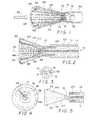
Figure 1 is a perspective view of the gripping device of the present invention;Figure 2 is a sectional view of the gripping device ofFigure 1 ;Figure 3 is a view in end elevation of the central support tube for the gripping device ofFigure 1 ;Figure 4 is a view in end elevation of the gripping device ofFigure 1 ;Figure 5 is a sectional view of the central support tube and a mandrel for forming a liner for the gripping device ofFigure 1 ; andFigure 6 is a perspective view of a second embodiment of the gripping device of the present invention.- Referring now to the drawings, the gripping device of the present invention indicated generally at 10 includes an elongate,
flexible support body 12 which is preferably an elongate, flexible tube having acentral channel 14 extending therethrough. Thechannel 14 is adapted to receive a guide wire for guiding a gripping device to a desired location within a body vessel. - The outermost end of the
flexible support body 12 is provided with a projectingend section 16 of reduced cross section relative to the remainder of the support body. When the support body is a flexible tube, the diameter of the projecting end section is less than the diameter of the remainder of the central tube to provide aflange 18 at the base of the projecting end section. Extending inwardly from theflange 18 in spaced relationship about the base of the projectingend section 16 are a plurality oflumens 20. - A plurality of spaced gripping
members 22 are mounted on the elongateflexible support body 12 to extend axially from the outer end thereof at an angle to thelongitudinal axis 24 of the elongate flexible support body. Each grippingmember 22 is formed by a length of wire which is looped at 26 to form the distal end of the gripping member. The two free ends of thewire 28 which form the proximal end of the gripping member are then inserted into one of thelumens 20 and are secured within the lumen. The gripping members are formed to surround the projectingend section 16 and are angled outwardly relative to thelongitudinal axis 24, preferably at a shallow angle of less than 45°. The wire gripping members are flexible and are formed to assume the expanded position ofFigures 1 and 2 when they are unrestrained. However, the wire gripping members may be moved inwardly toward thelongitudinal axis 24 to a restrained position. At least two diametrically opposed gripping members are provided at their respective distal ends with aprojection 30 with extends inwardly toward thelongitudinal axis 24. - If the
gripping members 22 were alone used in an attempt to grip ashaft 32 attached to a vena cava filter or some other implanted medical device, the shaft would be likely to pass angularly outward from thegripping device 10 between thegripping members 22. The shaft might even become lodged within the loop of one of the gripping members making it difficult to extract a device attached to the shaft and virtually impossible to reposition the device without completely removing the unit from the body vessel. Consequently, it is important to both prevent the shaft from passing between the gripping members and also to center the shaft within the gripping members so that a medical device which has been angularly mispositioned during implantation can be repositioned without being completely removed. To accomplish this, thegripping device 10 is provided with a flexible, openended liner 34. Preferably, theliner 34 is formed from a polymer such as polyurethane, although the liner could be formed of woven DACRON. As will be noted inFigure 2 , the innermost or closed end of theliner 34 is secured to the projectingend section 16, while the outermost end of the liner is secured to the looped distal ends of thegripping members 22. It is important to note that theliner 34 is unitary but formed in two sections. Aninnermost section 36 which extends from the projectingend 16 angles outwardly relative to thelongitudinal axis 24 at a greater angle than an outermost section of theliner 38. The outermost section of the liner extends at an angle which is substantially equal to the angle at which thegripping members 22 extend relative to thelongitudinal axis 24, and thus the outermost section of the liner lies against the gripping members. However, theinnermost section 36 of the liner extends at a greater angle relative to thelongitudinal axis 24 and is spaced from and gripping members. A liner having this configuration is preferably formed of a polymer, such as a urethane, by dipping on amandrel 40 shown inFigure 5 . Themandrel 40 is removably mounted in thecentral channel 14 of thesupport body 12, and is a circular, cone shaped mandrel having aninnermost section 42 formed to the angle of theinnermost section 36 of theliner 34 and anoutermost section 44 formed to the angle of theoutermost section 38 of the liner. With the mandrel in place as shown inFigure 5 , it and the projectingend section 16 are dipped in a molten polymer to form by the dipping process a thin,flexible liner 34. The outer end of the mandrel may be provided withprojections 46 to provide apertures in the liner which receive theprojections 30 on the grippingmembers 22. Now thewire gripping members 22 are inserted into thelumens 20 and affixed therein so that the gripping members extend along the outer surface of the liner. With the gripping members in place about the liner, the ends thereof are then again dipped in the molten polymer to create apolymer layer 48 which secures the liner to the distal ends of the gripping members. Once the liner is formed, themandrel 40 is removed leaving the liner affixed to the projectingend section 16. The flexibility of the liner permits theprojections 46 of the mandrel to disengage so that the mandrel can be removed. - To operate the
gripping device 10, aflexible catheter 50 or similar flexible outer tubular sheath surrounds theflexible support body 12 and is axially movable along the support body. With the outer tubular body in the position shown inFigures 1 and 2 , the grippingmembers 22 are in the expanded position to hold the liner open for the reception of the member such as theshaft 32. As the gripping device is moved over the shaft, the shaft will be centered within the gripping device by contact with theliner 34. The liner will prevent the shaft from passing outwardly between the grippingmembers 22 and will prevent the shaft from becoming lodged between the gripping members. Once the end of the shaft is in place adjacent to the projectingend section 16, the catheter or outertubular sheath 50 is moved axially to the left inFigures 1 and 2 to engage thegripping members 22 and force them inwardly toward thelongitudinal axis 24. Thus the gripping members and the liner will close inwardly about theshaft 32 to grip the shaft so that it and the device to which it is attached may be repositioned or drawn into thetube 50 by retracting theflexible support body 12. It is important to note that themetal gripping members 22 are external to theliner 34 and thus provide hard runner surfaces over which theouter tube 50 can slide without danger of engagement with the liner which might result in damage to the liner. The end of theouter tube 50 may be provided with a reinforcedring 52 to aid in contracting the grippingmembers 22, and the reinforcedring 52 may be made of metal to provide a radiopaque marker at the end of the outer tube orsheath 50. It is of course important for theprojections 30 to have a combined length that is less than the diameter of thesheath 50 so that the complete gripper device can be drawn within the sheath. - As shown by
Figure 6 , it is often desirable to form thegripping device 10 with only three or four loop shaped grippingmembers 22 which function primarily to expand the flexible open endedliner 34 and to engage and position afilter 53 to be removed. In this case, thefilter 53 is a removable filter having a plurality ofvessel engaging legs 54 which angle outwardly from acentral apex 56 at theshaft 32. With this filter configuration, it is advantageous for the gripping device to positively grip the filter in the area of the apex 56 rather than at the end of theshaft 32. To accomplish this, a plurality of flexible,elongate wire shafts 58 are positioned between the loop shaped grippingmembers 22. One end of eachshaft 58 is secured within alumen 20, and an inwardly projectinghook 60 is formed at the outermost end 62 of eachshaft 58. Theshafts 58, like thegripping members 22, extend along the outer surface of theliner 34 and lie against theoutermost section 38 of the liner. Like thehooks 30, thehooks 60 project inwardly trough the liner to form a plurality of inwardly projecting hooks spaced around the open end of the liner. - In the operation of the gripping device of
Figure 6 , thetubular sheath 50 surrounds thegripping device 10 and holds the device in a collapsed condition adjacent to the longitudinal axis of the device. In this configuration, the gripping device is adapted to travel through a body vessel until it reaches theshaft 32 of the expandedfilter 53. Now thesheath 50 is drawn back permitting the grippingmembers 22, theshafts 58 and theliner 34 to expand outwardly to the configuration shown inFigure 6 . Now the open end of the gripping device is moved over theshaft 32 and beyond the apex 56 of thefilter 53 so that thehooks 60 can extend between thefilter legs 54. Thetubular sheath 50 is moved forwardly over thesupport body 12 and into engagement with the grippingmembers 22 andshafts 58 to bring them into engagement with thefilter legs 54 below the apex 56. Thehooks 60 now pass between thefilter legs 54 below the apex while the grippingmembers 22 andliner 34 extend externally of the filter legs as the gripping members, liner andshafts 58 are moved by thesheath 50 inwardly toward the longitudinal axis of the gripping device. As thesupport body 12 is drawn into thesheath 50, the hooks positively engage thefilter apex 56 to draw the filter into the sheath. The gripping members and liner position the filter so that it is in alignment for withdrawal into the sheath. - The gripping device of the present invention may be employed within a body vessel for implanting, repositioning or extracting a medical device or other object. Since the gripping device operates to center an object which it grips, it may be employed to effectively reposition an angularly mispositioned filter or other medical unit without completely withdrawing the unit from a body vessel. The gripping device is also effective for removing small objects, such as kidney stones, from body vessels since it closes around these objects and prevents them from passing outwardly between the gripping
members 22. - 1. A gripping device operative within a body vessel for implanting, repositioning, or extracting an object comprising:
- an elongate support body having a central longitudinal axis and an outer end;
- a plurality of spaced gripping members attached to said support body to extend axially outwardly from the outer end thereof, each said gripping member having a proximal end secured to said support body and a distal end spaced from the outer end of said support body, said gripping members being formed to have an expansion position, when unrestrained, wherein the distal ends thereof are spaced laterally from said support body and to be movable, when restrained, inwardly from said expansion position toward the longitudinal axis of said support body; and
- a flexible liner forming an open ended enclosure in the expansion position of said gripping members, said flexible liner being connected to said gripping members.
- 2. The gripping device of paragraph 1 wherein said flexible liner is formed internally of said gripping members with said gripping members extending externally of said flexible liner.
- 3. The gripping device of paragraph 2 wherein said gripping members are formed of metal.
- 4. The gripping device of paragraph 1 wherein said gripping members include a plurality of loop members each formed from a length of wire looped to provide a loop at a distal end and two wire end sections at a proximal end, said wire end sections being attached to said support body.
- 5. The gripping device of paragraph 4 wherein said flexible liner is attached to the distal ends of said loop members and to the outer end of said support body.
- 6. The gripping device of paragraph 5 wherein said liner is formed internally of said gripping members with said gripping members extending externally of said flexible liner.
- 7. The gripping device of paragraph 6 wherein said flexible liner is formed of a polymer.
- 8. The gripping device of paragraph 6 wherein said gripping members in the expansion position angle outwardly from proximal to distal ends thereof at a first angle relative to said longitudinal axis, said flexible liner having a first section adjacent to the open end thereof which is inclined relative to said longitudinal axis at an angle substantially equal to said first angle, and a second section extending from said first section to said support body at an angle relative to said longitudinal axis which is greater than said first angle, said gripping members being spaced from said second section.
- 9. The gripping device of paragraph 2 wherein said elongate support body is a flexible tube which is formed at the outer end with a projecting end section of reduced diameter relative to the diameter of the remainder of the flexible tube to form a flange at the base of the reduced diameter end section where the end section meets the remainder of the flexible tube, and a plurality of spaced lumens are formed in said tube to extend longitudinally into the tube from said flange, said lumens being spaced around the base of the reduced diameter end section, the proximal end of a gripping member being received in a lumen.
- 10. The gripping device of paragraph 9 wherein said liner is attached to said reduced diameter end section.
- 11. The gripping device of
paragraph 10 wherein said gripping members include a plurality of looped members each formed from a length of wire looped to provide a loop at a distal end and two wire end sections at a proximal end, the wire end sections of each looped member being secured respectively in a lumen. - 12. The gripping device of paragraph 11 wherein said gripping members in the expansion position angle outwardly from the proximal to the distal ends thereof at a first angle relative to said longitudinal axis, said flexible liner having a first section adjacent to the open end thereof which is connected to the distal ends of said gripping members and which is inclined relative to said longitudinal axis at an angle substantially equal to said first angle, and a second section extending from said first section to said projecting end section of said flexible tube at an angle relative to said longitudinal axis which is greater than said first angle, said gripping members being spaced from said second section.
- 13. The gripping device of
paragraph 12 wherein the distal ends of at least two gripping members are positioned to be diametrically opposed, the diametrically opposed distal ends being provided with inwardly extending projections which pass through said liner and project inwardly therefrom. - 14. The gripping device of paragraph 1 which includes a restraining unit mounted on said support body in surrounding relationship thereto, said restraining unit being axially displaceable relative to said support body past the outer end thereof to engage said gripping members and move said gripping members toward said longitudinal axis to a restrained position and axially displaceable relative to said support body from engagement with said gripping members in the restrained position inwardly of the outer end of said support body to permit said gripping members to move to the expansion position.
- 15. The gripping device of
paragraph 14 wherein said support body is an elongate flexible central tube and said restraining unit is an outer tube surrounding said central tube. - 16. The gripping device of paragraph 15 wherein said flexible liner has an open end connected to the distal ends of said gripping members and a closed end connected to said central tube.
- 17. The gripping device of
paragraph 14 wherein said gripping members include hook members, each of which is formed from a length of wire having a hook at a distal end thereof. - 18. The gripping device of paragraph 17 wherein said support body is formed at the outer end with a projecting end section of reduced diameter relative to the diameter of the remainder of the support body, said closed end of said flexible liner being attached to said projecting end section, the proximal ends of said gripping members being secured to said support body around the periphery of said projecting end section.
- 19. The gripping device of
paragraph 18 wherein said gripping members in the expansion position angle outwardly from the proximal to the distal ends thereof at a first angle of less than 45° relative to said longitudinal axis, said flexible liner having a first section adjacent to the open end thereof which is connected to the distal ends of said gripping members and which is inclined relative to said longitudinal axis at an angle substantially equal to said first angle, and a second section extending from said first section to said projecting end section of said flexible tube at an angle relative to said longitudinal axis which is greater than said first angle, said gripping members being spaced from said second section. - 20. The gripping device of paragraph 17 wherein said gripping members include a plurality of loop members each formed from a length of wire looped to provide a hoop at a distal end and two wire sections at a proximal end, said wire sections being attached to said support body.
Claims (13)
- A gripping device operative within a body vessel for implanting, repositioning, or extracting an object comprising:an elongate support body having a central longitudinal axis and an outer end;a plurality of spaced gripping members attached to said support body to extend axially outwardly from the outer end thereof, each said gripping member having a proximal end secured to said support body and a distal end spaced from the outer end of said support body, said gripping members being formed to have an expansion position, when unrestrained, wherein the distal ends thereof are spaced laterally from said support body and to be movable, when restrained, inwardly from said expansion position toward the longitudinal axis of said support body; anda flexible liner forming an open ended enclosure in the expansion position of said gripping members, said flexible liner being connected to said gripping members, wherein said gripping members in the expansion position angle outwardly from proximal to distal ends thereof at a first angle relative to said longitudinal axis, said flexible liner having a first section adjacent to the open end thereof which is inclined relative to said longitudinal axis at an angle substantially equal to said first angle, and a second section extending from said first section to said support body at an angle relative to said longitudinal axis which is greater than said first angle, said gripping members being spaced from said second section.
- The gripping device of claim 1 wherein said flexible liner is formed internally of said gripping members with said gripping members extending externally of said flexible liner.
- The gripping device of claim 1 or 2 wherein said gripping members are formed of metal.
- The gripping device of claim 1, 2 or 3 wherein said gripping members include a plurality of loop members each formed from a length of wire looped to provide a loop at a distal end and two wire end sections at a proximal end, said wire end sections being attached to said support body.
- The gripping device of claim 4 wherein said liner is formed internally of said gripping members with said gripping members extending externally of said flexible liner.
- The gripping device of any one of the preceding claims wherein said flexible liner is formed of a polymer.
- The gripping device of any one of the preceding claims wherein the distal ends of at least two gripping members are provided with inwardly extending projections.
- The gripping device of any one of the preceding claims which includes a restraining unit mounted on said support body in surrounding relationship thereto, said restraining unit being axially displaceable relative to said support body past the outer end thereof to engage said gripping members and move said gripping members toward said longitudinal axis to a restrained position and axially displaceable relative to said support body from engagement with said gripping members in the restrained position inwardly of the outer end of said support body to permit said gripping members to move to the expansion position.
- The gripping device of claim 8 wherein said support body is an elongate flexible central tube and said restraining unit is an outer tube surrounding said central tube.
- The gripping device of any one of the preceding claims wherein said flexible liner has an open end connected to said gripping members and a closed end connected to said support body.
- The gripping device of any one of the preceding claims wherein said gripping members include hook members, each of which is formed from a length of wire having a hook at a distal end thereof.
- The gripping device of any one of the preceding claims wherein said support body is formed at the outer end with a projecting end section of reduced diameter relative to the diameter of the remainder of the support body, said flexible liner being attached to said projecting end section, the proximal ends of said gripping members being secured to said support body around the periphery of said projecting end section.
- The gripping device of any one of the preceding claims wherein said first angle is less than 45°.
Priority Applications (1)
| Application Number | Priority Date | Filing Date | Title |
|---|---|---|---|
| EP10183528.8AEP2298195B1 (en) | 1999-03-23 | 2000-03-20 | Gripping device for implanting, repositioning or extracting an object within a body vessel |
Applications Claiming Priority (2)
| Application Number | Priority Date | Filing Date | Title |
|---|---|---|---|
| US09/274,108US6156055A (en) | 1999-03-23 | 1999-03-23 | Gripping device for implanting, repositioning or extracting an object within a body vessel |
| EP00914934AEP1164945B1 (en) | 1999-03-23 | 2000-03-20 | Gripping device for implanting, repositioning or extracting an object within a body vessel |
Related Parent Applications (2)
| Application Number | Title | Priority Date | Filing Date |
|---|---|---|---|
| EP00914934ADivisionEP1164945B1 (en) | 1999-03-23 | 2000-03-20 | Gripping device for implanting, repositioning or extracting an object within a body vessel |
| EP00914934.5Division | 2000-03-20 |
Related Child Applications (2)
| Application Number | Title | Priority Date | Filing Date |
|---|---|---|---|
| EP10183528.8ADivisionEP2298195B1 (en) | 1999-03-23 | 2000-03-20 | Gripping device for implanting, repositioning or extracting an object within a body vessel |
| EP10183528.8Division-Into | 2010-09-30 |
Publications (2)
| Publication Number | Publication Date |
|---|---|
| EP2014245A1true EP2014245A1 (en) | 2009-01-14 |
| EP2014245B1 EP2014245B1 (en) | 2011-10-26 |
Family
ID=23046803
Family Applications (3)
| Application Number | Title | Priority Date | Filing Date |
|---|---|---|---|
| EP00914934AExpired - LifetimeEP1164945B1 (en) | 1999-03-23 | 2000-03-20 | Gripping device for implanting, repositioning or extracting an object within a body vessel |
| EP10183528.8AExpired - LifetimeEP2298195B1 (en) | 1999-03-23 | 2000-03-20 | Gripping device for implanting, repositioning or extracting an object within a body vessel |
| EP08168040AExpired - LifetimeEP2014245B1 (en) | 1999-03-23 | 2000-03-20 | Gripping device for implanting, repositioning or extracting an object within a body vessel |
Family Applications Before (2)
| Application Number | Title | Priority Date | Filing Date |
|---|---|---|---|
| EP00914934AExpired - LifetimeEP1164945B1 (en) | 1999-03-23 | 2000-03-20 | Gripping device for implanting, repositioning or extracting an object within a body vessel |
| EP10183528.8AExpired - LifetimeEP2298195B1 (en) | 1999-03-23 | 2000-03-20 | Gripping device for implanting, repositioning or extracting an object within a body vessel |
Country Status (9)
| Country | Link |
|---|---|
| US (1) | US6156055A (en) |
| EP (3) | EP1164945B1 (en) |
| JP (2) | JP4132681B2 (en) |
| AT (2) | ATE416693T1 (en) |
| CA (1) | CA2366716C (en) |
| DE (1) | DE60041043D1 (en) |
| DK (2) | DK2014245T3 (en) |
| ES (2) | ES2372224T3 (en) |
| WO (1) | WO2000056231A1 (en) |
Cited By (2)
| Publication number | Priority date | Publication date | Assignee | Title |
|---|---|---|---|---|
| US11690651B2 (en) | 2015-09-04 | 2023-07-04 | The Trustees Of The University Of Pennsylvania | Systems and methods for percutaneous removal of objects from an internal body space |
| US12082845B2 (en) | 2015-09-04 | 2024-09-10 | The Trustees Of The University Of Pennsylvania | Systems and methods for percutaneous removal of objects from an internal body space |
Families Citing this family (224)
| Publication number | Priority date | Publication date | Assignee | Title |
|---|---|---|---|---|
| US7314477B1 (en) | 1998-09-25 | 2008-01-01 | C.R. Bard Inc. | Removable embolus blood clot filter and filter delivery unit |
| US7128073B1 (en) | 1998-11-06 | 2006-10-31 | Ev3 Endovascular, Inc. | Method and device for left atrial appendage occlusion |
| US7044134B2 (en)* | 1999-11-08 | 2006-05-16 | Ev3 Sunnyvale, Inc | Method of implanting a device in the left atrial appendage |
| US7713282B2 (en)* | 1998-11-06 | 2010-05-11 | Atritech, Inc. | Detachable atrial appendage occlusion balloon |
| WO2000044428A1 (en)* | 1999-01-28 | 2000-08-03 | Ansamed Limited | Catheter with an expandable end portion |
| US6752813B2 (en) | 1999-04-09 | 2004-06-22 | Evalve, Inc. | Methods and devices for capturing and fixing leaflets in valve repair |
| FR2794653B1 (en)* | 1999-06-14 | 2001-12-21 | Sarl Aln | KIT FOR THE REMOVAL OF A BLADDER VESSEL FILTER OF THE UMBRELLA TYPE |
| EP1210014A1 (en) | 1999-09-07 | 2002-06-05 | Microvena Corporation | Retrievable septal defect closure device |
| US6939361B1 (en) | 1999-09-22 | 2005-09-06 | Nmt Medical, Inc. | Guidewire for a free standing intervascular device having an integral stop mechanism |
| JP3742542B2 (en)* | 2000-03-10 | 2006-02-08 | ペンタックス株式会社 | Endoscope foreign matter collection tool |
| US6361540B1 (en)* | 2000-04-06 | 2002-03-26 | Michael W. L. Gauderer | Apparatus for removal of esophageal coins and similarly shaped objects |
| US6440152B1 (en) | 2000-07-28 | 2002-08-27 | Microvena Corporation | Defect occluder release assembly and method |
| US7727253B2 (en) | 2000-11-03 | 2010-06-01 | Cook Incorporated | Medical grasping device having embolic protection |
| US7776052B2 (en) | 2000-11-03 | 2010-08-17 | Cook Incorporated | Medical grasping device |
| US7753917B2 (en) | 2000-11-03 | 2010-07-13 | Cook Incorporated | Medical grasping device |
| US7713275B2 (en) | 2000-11-03 | 2010-05-11 | Cook Incorporated | Medical grasping device |
| US7806906B2 (en)* | 2001-03-12 | 2010-10-05 | Don Michael T Anthony | Vascular filter with improved strength and flexibility |
| US20020183781A1 (en)* | 2001-04-17 | 2002-12-05 | Brendan Casey | Catheter |
| US7288105B2 (en) | 2001-08-01 | 2007-10-30 | Ev3 Endovascular, Inc. | Tissue opening occluder |
| DE10148185B4 (en)* | 2001-09-28 | 2005-08-11 | Alveolus, Inc. | Instrument for implanting vascular prostheses |
| US9204956B2 (en) | 2002-02-20 | 2015-12-08 | C. R. Bard, Inc. | IVC filter with translating hooks |
| EP1596723A2 (en) | 2003-02-04 | 2005-11-23 | ev3 Sunnyvale, Inc. | Patent foramen ovale closure system |
| WO2004071343A2 (en) | 2003-02-11 | 2004-08-26 | Cook, Inc. | Removable vena cava filter |
| US7658747B2 (en)* | 2003-03-12 | 2010-02-09 | Nmt Medical, Inc. | Medical device for manipulation of a medical implant |
| US10631871B2 (en) | 2003-05-19 | 2020-04-28 | Evalve, Inc. | Fixation devices, systems and methods for engaging tissue |
| US7735493B2 (en)* | 2003-08-15 | 2010-06-15 | Atritech, Inc. | System and method for delivering a left atrial appendage containment device |
| US20050192626A1 (en) | 2004-01-30 | 2005-09-01 | Nmt Medical, Inc. | Devices, systems, and methods for closure of cardiac openings |
| US7323003B2 (en)* | 2004-02-13 | 2008-01-29 | Boston Scientific Scimed, Inc. | Centering intravascular filters and devices and methods for deploying and retrieving intravascular filters |
| US7686825B2 (en) | 2004-03-25 | 2010-03-30 | Hauser David L | Vascular filter device |
| US8105349B2 (en) | 2004-04-16 | 2012-01-31 | Cook Medical Technologies Llc | Removable vena cava filter having primary struts for enhanced retrieval and delivery |
| US7699867B2 (en) | 2004-04-16 | 2010-04-20 | Cook Incorporated | Removable vena cava filter for reduced trauma in collapsed configuration |
| US7625390B2 (en) | 2004-04-16 | 2009-12-01 | Cook Incorporated | Removable vena cava filter |
| US8043322B2 (en) | 2004-04-16 | 2011-10-25 | Cook Medical Technologies Llc | Removable vena cava filter having inwardly positioned anchoring hooks in collapsed configuration |
| CA2563372C (en) | 2004-04-16 | 2012-08-07 | Cook, Inc. | Removable vena cava filter with anchoring feature for reduced trauma |
| US7704267B2 (en) | 2004-08-04 | 2010-04-27 | C. R. Bard, Inc. | Non-entangling vena cava filter |
| US9655633B2 (en) | 2004-09-10 | 2017-05-23 | Penumbra, Inc. | System and method for treating ischemic stroke |
| US7931659B2 (en)* | 2004-09-10 | 2011-04-26 | Penumbra, Inc. | System and method for treating ischemic stroke |
| US20060058837A1 (en)* | 2004-09-10 | 2006-03-16 | Arani Bose | System and method for treating ischemic stroke |
| ATE516772T1 (en) | 2004-09-27 | 2011-08-15 | Cook Inc | REMOVABLE VENA CAVA FILTER |
| US7959645B2 (en)* | 2004-11-03 | 2011-06-14 | Boston Scientific Scimed, Inc. | Retrievable vena cava filter |
| US7794473B2 (en) | 2004-11-12 | 2010-09-14 | C.R. Bard, Inc. | Filter delivery system |
| DE102005003632A1 (en) | 2005-01-20 | 2006-08-17 | Fraunhofer-Gesellschaft zur Förderung der angewandten Forschung e.V. | Catheter for the transvascular implantation of heart valve prostheses |
| US8267954B2 (en) | 2005-02-04 | 2012-09-18 | C. R. Bard, Inc. | Vascular filter with sensing capability |
| US7993362B2 (en)* | 2005-02-16 | 2011-08-09 | Boston Scientific Scimed, Inc. | Filter with positioning and retrieval devices and methods |
| US8025668B2 (en)* | 2005-04-28 | 2011-09-27 | C. R. Bard, Inc. | Medical device removal system |
| US8613754B2 (en) | 2005-05-12 | 2013-12-24 | C. R. Bard, Inc. | Tubular filter |
| CA2607580C (en) | 2005-05-12 | 2016-12-20 | C.R. Bard Inc. | Removable embolus blood clot filter |
| US12115057B2 (en) | 2005-05-12 | 2024-10-15 | C.R. Bard, Inc. | Tubular filter |
| WO2007021340A1 (en) | 2005-08-09 | 2007-02-22 | C.R. Bard Inc | Embolus blood clot filter and delivery system |
| US7972359B2 (en) | 2005-09-16 | 2011-07-05 | Atritech, Inc. | Intracardiac cage and method of delivering same |
| US9131999B2 (en) | 2005-11-18 | 2015-09-15 | C.R. Bard Inc. | Vena cava filter with filament |
| US9034006B2 (en)* | 2005-12-01 | 2015-05-19 | Atritech, Inc. | Method and apparatus for retrieving an embolized implant |
| US8052715B2 (en)* | 2005-12-01 | 2011-11-08 | Atritech, Inc. | Method and apparatus for recapturing an implant from the left atrial appendage |
| US20070135826A1 (en) | 2005-12-01 | 2007-06-14 | Steve Zaver | Method and apparatus for delivering an implant without bias to a left atrial appendage |
| CA2630447A1 (en)* | 2005-12-02 | 2007-06-07 | C.R. Bard, Inc. | Helical vena cava filter |
| US20090105747A1 (en)* | 2005-12-07 | 2009-04-23 | C.R. Bard, Inc. | Vena Cava Filter with Stent |
| WO2007079407A2 (en)* | 2005-12-30 | 2007-07-12 | C.R. Bard Inc. | Embolus blood clot filter with post delivery actuation |
| US8317818B2 (en)* | 2005-12-30 | 2012-11-27 | C.R. Bard, Inc. | Removable blood clot filter with edge for cutting through the endothelium |
| US9730781B2 (en) | 2005-12-30 | 2017-08-15 | C. R. Bard, Inc. | Embolus blood clot filter removal system and method |
| US8562638B2 (en) | 2005-12-30 | 2013-10-22 | C.R. Bard, Inc. | Embolus blood clot filter with floating filter basket |
| WO2007079410A2 (en) | 2005-12-30 | 2007-07-12 | C.R Bard Inc. | Embolus blood clot filter delivery system |
| US9107733B2 (en) | 2006-01-13 | 2015-08-18 | W. L. Gore & Associates, Inc. | Removable blood conduit filter |
| WO2007133366A2 (en) | 2006-05-02 | 2007-11-22 | C. R. Bard, Inc. | Vena cava filter formed from a sheet |
| US9326842B2 (en) | 2006-06-05 | 2016-05-03 | C. R . Bard, Inc. | Embolus blood clot filter utilizable with a single delivery system or a single retrieval system in one of a femoral or jugular access |
| US9232997B2 (en) | 2006-11-07 | 2016-01-12 | Corvia Medical, Inc. | Devices and methods for retrievable intra-atrial implants |
| US8460372B2 (en) | 2006-11-07 | 2013-06-11 | Dc Devices, Inc. | Prosthesis for reducing intra-cardiac pressure having an embolic filter |
| US10413284B2 (en) | 2006-11-07 | 2019-09-17 | Corvia Medical, Inc. | Atrial pressure regulation with control, sensing, monitoring and therapy delivery |
| EP2097012A4 (en) | 2006-11-07 | 2012-08-15 | David Stephen Celermajer | Devices and methods for the treatment of heart failure |
| US20110257723A1 (en) | 2006-11-07 | 2011-10-20 | Dc Devices, Inc. | Devices and methods for coronary sinus pressure relief |
| US8460369B2 (en)* | 2007-01-18 | 2013-06-11 | Valvexchange Inc. | Tools for removal and installation of exchangeable cardiovascular valves |
| US7896915B2 (en) | 2007-04-13 | 2011-03-01 | Jenavalve Technology, Inc. | Medical device for treating a heart valve insufficiency |
| CA2696055C (en) | 2007-08-21 | 2013-12-10 | Valvexchange Inc. | Method and apparatus for prosthetic valve removal |
| US8795318B2 (en) | 2007-09-07 | 2014-08-05 | Merit Medical Systems, Inc. | Percutaneous retrievable vascular filter |
| WO2009032834A1 (en) | 2007-09-07 | 2009-03-12 | Crusader Medical Llc | Percutaneous permanent retrievable vascular filter |
| US8246672B2 (en) | 2007-12-27 | 2012-08-21 | Cook Medical Technologies Llc | Endovascular graft with separately positionable and removable frame units |
| US8114116B2 (en) | 2008-01-18 | 2012-02-14 | Cook Medical Technologies Llc | Introduction catheter set for a self-expandable implant |
| BR112012021347A2 (en) | 2008-02-26 | 2019-09-24 | Jenavalve Tecnology Inc | stent for positioning and anchoring a valve prosthesis at an implantation site in a patient's heart |
| US9044318B2 (en) | 2008-02-26 | 2015-06-02 | Jenavalve Technology Gmbh | Stent for the positioning and anchoring of a valvular prosthesis |
| WO2010030859A1 (en) | 2008-09-12 | 2010-03-18 | Valvexchange Inc. | Valve assembly with exchangeable valve member and a tool set for exchanging the valve member |
| EP3238661B1 (en)* | 2008-10-10 | 2019-05-22 | Boston Scientific Scimed, Inc. | Medical devices and delivery systems for delivering medical devices |
| US8246648B2 (en) | 2008-11-10 | 2012-08-21 | Cook Medical Technologies Llc | Removable vena cava filter with improved leg |
| US20100249815A1 (en)* | 2009-03-25 | 2010-09-30 | Cook Incorporated | Everted sheath thrombectomy device |
| WO2011017189A1 (en)* | 2009-08-04 | 2011-02-10 | Wilson-Cook Medical Inc. | Roll sleeve mechanism for proximal release stent delivery device |
| US9757107B2 (en) | 2009-09-04 | 2017-09-12 | Corvia Medical, Inc. | Methods and devices for intra-atrial shunts having adjustable sizes |
| WO2011094521A2 (en) | 2010-01-29 | 2011-08-04 | Dc Devices, Inc. | Devices and methods for reducing venous pressure |
| EP2528646A4 (en) | 2010-01-29 | 2017-06-28 | DC Devices, Inc. | Devices and systems for treating heart failure |
| US8512401B2 (en)* | 2010-04-12 | 2013-08-20 | Medtronic, Inc. | Transcatheter prosthetic heart valve delivery system with funnel recapturing feature and method |
| US8974469B2 (en) | 2010-04-22 | 2015-03-10 | Medical Device Technologies, Inc. | Snare |
| US10856978B2 (en) | 2010-05-20 | 2020-12-08 | Jenavalve Technology, Inc. | Catheter system |
| WO2011147849A1 (en) | 2010-05-25 | 2011-12-01 | Jenavalve Technology Inc. | Prosthetic heart valve and transcatheter delivered endoprosthesis comprising a prosthetic heart valve and a stent |
| US10022212B2 (en) | 2011-01-13 | 2018-07-17 | Cook Medical Technologies Llc | Temporary venous filter with anti-coagulant delivery method |
| WO2012109557A2 (en) | 2011-02-10 | 2012-08-16 | Dc Devices, Inc. | Apparatus and methods to create and maintain an intra-atrial pressure relief opening |
| US12303119B2 (en) | 2011-02-10 | 2025-05-20 | Corvia Medical, Inc. | Apparatus and methods to create and maintain an intra-atrial pressure relief opening |
| US8734480B2 (en) | 2011-08-05 | 2014-05-27 | Merit Medical Systems, Inc. | Vascular filter |
| US8740931B2 (en) | 2011-08-05 | 2014-06-03 | Merit Medical Systems, Inc. | Vascular filter |
| US9011468B2 (en)* | 2011-09-13 | 2015-04-21 | Abbott Cardiovascular Systems Inc. | Independent gripper |
| US8945177B2 (en) | 2011-09-13 | 2015-02-03 | Abbott Cardiovascular Systems Inc. | Gripper pusher mechanism for tissue apposition systems |
| US12096951B2 (en) | 2011-10-05 | 2024-09-24 | Penumbra, Inc. | System and method for treating ischemic stroke |
| US10010437B2 (en) | 2011-10-17 | 2018-07-03 | W. L. Gore & Associates, Inc. | Endoluminal device retrieval devices and related systems and methods |
| US8951223B2 (en) | 2011-12-22 | 2015-02-10 | Dc Devices, Inc. | Methods and devices for intra-atrial shunts having adjustable sizes |
| US9005155B2 (en) | 2012-02-03 | 2015-04-14 | Dc Devices, Inc. | Devices and methods for treating heart failure |
| EP2816969B1 (en) | 2012-02-23 | 2018-06-13 | Merit Medical Systems, Inc. | Vascular filter |
| US11134981B2 (en) | 2012-03-29 | 2021-10-05 | Gyrus Acmi, Inc. | Pulmonary nodule access devices and methods of using the same |
| DE112013001718T5 (en)* | 2012-03-29 | 2014-12-11 | Spiration, Inc. | Medical devices and systems for manipulating foreign bodies and methods for their use |
| US10588611B2 (en) | 2012-04-19 | 2020-03-17 | Corvia Medical Inc. | Implant retention attachment and method of use |
| US9649480B2 (en) | 2012-07-06 | 2017-05-16 | Corvia Medical, Inc. | Devices and methods of treating or ameliorating diastolic heart failure through pulmonary valve intervention |
| US9101449B2 (en) | 2012-07-27 | 2015-08-11 | Cook Medical Technologies Llc | Filter removal device |
| US8784434B2 (en) | 2012-11-20 | 2014-07-22 | Inceptus Medical, Inc. | Methods and apparatus for treating embolism |
| US9055930B2 (en) | 2012-12-17 | 2015-06-16 | Cook Medical Technologies Llc | Device for preparing an implanted medical apparatus for extraction |
| US10154833B2 (en) | 2013-03-01 | 2018-12-18 | Covidien Lp | Specimen retrieval device with pouch stop |
| US9775636B2 (en) | 2013-03-12 | 2017-10-03 | Corvia Medical, Inc. | Devices, systems, and methods for treating heart failure |
| US10219864B2 (en) | 2013-04-16 | 2019-03-05 | Calcula Technologies, Inc. | Basket and everting balloon with simplified design and control |
| US8974472B2 (en) | 2013-04-16 | 2015-03-10 | Calcula Technologies, Inc. | Method for removing kidney stones |
| US10188411B2 (en) | 2013-04-16 | 2019-01-29 | Calcula Technologies, Inc. | Everting balloon for medical devices |
| EP3666227A1 (en)* | 2013-06-14 | 2020-06-17 | Avantec Vascular Corporation | Inferior vena cava filter and retrieval systems |
| EP3030194B1 (en) | 2013-08-09 | 2019-03-13 | Merit Medical Systems, Inc. | Vascular filter delivery systems |
| WO2015027166A2 (en) | 2013-08-23 | 2015-02-26 | Covidien Lp | Specimen retrieval device |
| CN105491978A (en) | 2013-08-30 | 2016-04-13 | 耶拿阀门科技股份有限公司 | Radially collapsible frame for a prosthetic valve and method for manufacturing such a frame |
| US10238406B2 (en) | 2013-10-21 | 2019-03-26 | Inari Medical, Inc. | Methods and apparatus for treating embolism |
| US10675450B2 (en) | 2014-03-12 | 2020-06-09 | Corvia Medical, Inc. | Devices and methods for treating heart failure |
| JP6799526B2 (en) | 2014-07-23 | 2020-12-16 | コルヴィア メディカル インコーポレイテッド | Equipment and methods for the treatment of heart failure |
| JP6601501B2 (en) | 2014-11-04 | 2019-11-13 | ニプロ株式会社 | Catheter device internally provided with a longitudinal inflation element for compressing cancellous bone |
| EP3229729B1 (en)* | 2014-12-12 | 2023-03-15 | Avantec Vascular Corporation | Ivc filter retrieval systems with interposed support members |
| EP3229726B1 (en)* | 2014-12-12 | 2020-10-28 | Avantec Vascular Corporation | Shaping improvements for inferior vena cava filter and retrieval systems |
| US10278804B2 (en) | 2014-12-12 | 2019-05-07 | Avantec Vascular Corporation | IVC filter retrieval systems with releasable capture feature |
| US10524810B2 (en) | 2015-03-04 | 2020-01-07 | Gyrus Acmi, Inc. | Medical device for capturing stone fragments |
| EP3270825B1 (en) | 2015-03-20 | 2020-04-22 | JenaValve Technology, Inc. | Heart valve prosthesis delivery system |
| US10524912B2 (en) | 2015-04-02 | 2020-01-07 | Abbott Cardiovascular Systems, Inc. | Tissue fixation devices and methods |
| US10709555B2 (en) | 2015-05-01 | 2020-07-14 | Jenavalve Technology, Inc. | Device and method with reduced pacemaker rate in heart valve replacement |
| US10245072B2 (en) | 2015-07-10 | 2019-04-02 | Medtronic, Inc. | Extravascular medical access tools having boring tip and methods of using such tools |
| CN108348319B (en) | 2015-09-28 | 2020-03-10 | 斯瑞克公司 | Mechanical embolectomy device and method |
| US10758729B2 (en)* | 2015-10-01 | 2020-09-01 | Medtronic, Inc. | Interventional medical systems, catheters, and methods |
| US9844664B2 (en) | 2015-10-12 | 2017-12-19 | Medtronic, Inc. | Interventional medical systems, catheters, and subassemblies |
| CN113796927B (en) | 2015-10-23 | 2025-03-04 | 伊纳里医疗公司 | Intravascular treatment of vascular occlusion and related devices, systems and methods |
| US10080888B2 (en) | 2015-11-16 | 2018-09-25 | Medtronic, Inc. | Interventional medical systems and associated methods |
| WO2017100563A1 (en)* | 2015-12-10 | 2017-06-15 | Avantec Vascular Corporation | Ivc filter retrieval system sheath improvements |
| US11896247B2 (en) | 2016-04-25 | 2024-02-13 | Stryker Corporation | Inverting mechanical thrombectomy apparatuses |
| EP3590446B1 (en) | 2016-04-25 | 2021-01-06 | Stryker Corporation | Anti-jamming and macerating thrombectomy apparatuses |
| WO2017189591A1 (en) | 2016-04-25 | 2017-11-02 | Stryker Corporation | Inverting mechanical thrombectomy apparatuses and methods of use in the vasculature |
| EP3448276B1 (en) | 2016-04-25 | 2020-03-04 | Stryker Corporation | Clot-engulfing mechanical thrombectomy apparatuses |
| US11497512B2 (en) | 2016-04-25 | 2022-11-15 | Stryker Corporation | Inverting thrombectomy apparatuses and methods |
| WO2017195125A1 (en) | 2016-05-13 | 2017-11-16 | Jenavalve Technology, Inc. | Heart valve prosthesis delivery system and method for delivery of heart valve prosthesis with introducer sheath and loading system |
| CN109561903B (en) | 2016-06-03 | 2021-07-27 | 斯瑞克公司 | Flip thrombectomy device |
| WO2018049317A1 (en) | 2016-09-12 | 2018-03-15 | Stryker Corporation | Self-rolling thrombectomy apparatuses and methods |
| FI3528717T3 (en) | 2016-10-24 | 2024-08-09 | Inari Medical Inc | Devices for treating vascular occlusion |
| JP7145852B2 (en)* | 2016-11-11 | 2022-10-03 | ベルント・ビュッシャーホフ | A device for removing organs from the human or animal body |
| CN110167482A (en) | 2016-12-22 | 2019-08-23 | 阿万泰血管公司 | Systems, devices and methods for retrieval systems with tethers |
| US10675058B2 (en) | 2017-01-19 | 2020-06-09 | Covidien Lp | Devices, systems, and methods for large tissue specimen removal |
| WO2018138658A1 (en) | 2017-01-27 | 2018-08-02 | Jenavalve Technology, Inc. | Heart valve mimicry |
| US11376039B2 (en) | 2017-03-30 | 2022-07-05 | Medtronic, Inc. | Interventional medical systems and associated assemblies |
| EP3614933A1 (en) | 2017-04-27 | 2020-03-04 | Boston Scientific Scimed, Inc. | Occlusive medical device with fabric retention barb |
| US10716594B2 (en)* | 2017-06-12 | 2020-07-21 | Covidien Lp | Devices, systems, and methods for tissue specimen removal |
| US10653400B2 (en) | 2017-08-07 | 2020-05-19 | Covidien Lp | Specimen retrieval device |
| WO2019050765A1 (en) | 2017-09-06 | 2019-03-14 | Inari Medical, Inc. | Hemostasis valves and methods of use |
| US11083490B2 (en) | 2017-09-21 | 2021-08-10 | Covidien Lp | Systems and methods for large tissue specimen removal |
| US11065051B2 (en) | 2017-11-03 | 2021-07-20 | Covidien Lp | Specimen retrieval device |
| US20190133742A1 (en)* | 2017-11-07 | 2019-05-09 | Mohammad Reza Rajebi | Ivc filter retrieval kit |
| EP4176830A1 (en) | 2017-11-09 | 2023-05-10 | Stryker Corporation | Inverting thrombectomy apparatuses having enhanced tracking |
| EP3727164B1 (en) | 2017-12-18 | 2024-03-13 | Boston Scientific Scimed, Inc. | Occlusive device with expandable member |
| US10973543B2 (en) | 2018-01-10 | 2021-04-13 | Covidien Lp | Dual wall tissue extraction bag |
| US11413048B2 (en) | 2018-01-19 | 2022-08-16 | Boston Scientific Scimed, Inc. | Occlusive medical device with delivery system |
| US10874386B2 (en) | 2018-01-24 | 2020-12-29 | Covidien Lp | Specimen retrieval device |
| US11154314B2 (en) | 2018-01-26 | 2021-10-26 | Inari Medical, Inc. | Single insertion delivery system for treating embolism and associated systems and methods |
| US11730459B2 (en) | 2018-02-22 | 2023-08-22 | Covidien Lp | Specimen retrieval devices and methods |
| US10792057B2 (en) | 2018-03-23 | 2020-10-06 | Covidien Lp | Articulation mechanisms for tissue specimen retrieval devices and tissue specimen retrieval devices incorporating the same |
| US11083443B2 (en) | 2018-04-24 | 2021-08-10 | Covidien Lp | Specimen retrieval device |
| EP4512318A3 (en) | 2018-05-02 | 2025-04-09 | Boston Scientific Scimed, Inc. | Occlusive sealing sensor system |
| US10667800B2 (en) | 2018-05-08 | 2020-06-02 | Covidien Lp | Four bar articulation mechanism for tissue specimen retrieval device |
| WO2019222117A1 (en) | 2018-05-14 | 2019-11-21 | Stryker Corporation | Inverting thrombectomy apparatuses and methods of use |
| US11241239B2 (en) | 2018-05-15 | 2022-02-08 | Boston Scientific Scimed, Inc. | Occlusive medical device with charged polymer coating |
| US11045176B2 (en) | 2018-05-18 | 2021-06-29 | Covidien Lp | Specimen retrieval device |
| US10792023B2 (en) | 2018-06-06 | 2020-10-06 | Covidien Lp | Shaft driven mechanism for articulating tissue specimen retrieval device |
| US11123079B2 (en) | 2018-06-08 | 2021-09-21 | Boston Scientific Scimed, Inc. | Occlusive device with actuatable fixation members |
| EP3801300A1 (en) | 2018-06-08 | 2021-04-14 | Boston Scientific Scimed, Inc. | Medical device with occlusive member |
| CN112584799A (en) | 2018-06-29 | 2021-03-30 | 阿万泰血管公司 | Systems and methods for implants and deployment devices |
| US11382635B2 (en) | 2018-07-06 | 2022-07-12 | Boston Scientific Scimed, Inc. | Occlusive medical device |
| CA3114285A1 (en) | 2018-08-13 | 2020-02-20 | Inari Medical, Inc. | System for treating embolism and associated devices and methods |
| US11134932B2 (en) | 2018-08-13 | 2021-10-05 | Covidien Lp | Specimen retrieval device |
| CN112714632B (en) | 2018-08-21 | 2024-08-30 | 波士顿科学医学有限公司 | Barbed protruding member for cardiovascular device |
| CN112969420B (en) | 2018-09-10 | 2024-12-17 | 史赛克公司 | Inverted thrombectomy device and method of using thrombectomy device |
| CN112702961A (en) | 2018-09-10 | 2021-04-23 | 斯瑞克公司 | Laser grooving and grabbing device |
| US11730480B2 (en) | 2018-09-14 | 2023-08-22 | Covidien Lp | Method and apparatus for accessing matter disposed within an internal body vessel |
| US11191559B2 (en) | 2018-09-19 | 2021-12-07 | Covidien Lp | Specimen retrieval device |
| US10912545B2 (en) | 2019-02-04 | 2021-02-09 | Covidien Lp | Tissue specimen retrieval devices and methods |
| US11344300B2 (en) | 2019-03-26 | 2022-05-31 | Covidien Lp | Specimen capture stapler |
| US11172915B2 (en) | 2019-04-24 | 2021-11-16 | Covidien Lp | Specimen retrieval devices with selective bag release |
| US11246578B2 (en) | 2019-05-15 | 2022-02-15 | Covidien Lp | Tissue collection bags with inner surface pouches |
| US11051834B2 (en) | 2019-05-17 | 2021-07-06 | Covidien Lp | Tissue specimen retrieval device |
| US11426203B2 (en) | 2019-05-23 | 2022-08-30 | Covidien Lp | Tissue guards and systems incorporating the same for tissue specimen removal procedures and other surgical procedures |
| US11426151B2 (en) | 2019-06-04 | 2022-08-30 | Covidien Lp | Bag closure for specimen retrieval device |
| CA3147410A1 (en) | 2019-07-15 | 2021-01-21 | Evalve, Inc. | Proximal element actuator fixation and release mechanisms |
| JP7543391B2 (en) | 2019-07-15 | 2024-09-02 | エバルブ,インコーポレイティド | Method of Actuating Individual Proximal Elements |
| CN114126540A (en) | 2019-07-17 | 2022-03-01 | 波士顿科学医学有限公司 | Continuously covered left atrial appendage implant |
| US11051795B2 (en) | 2019-07-31 | 2021-07-06 | Covidien Lp | Tissue retrieval bag |
| US11304687B2 (en) | 2019-08-13 | 2022-04-19 | Covidien Lp | Tissue specimen bag furling device and method |
| EP4563099A3 (en) | 2019-08-30 | 2025-08-06 | Boston Scientific Scimed, Inc. | Left atrial appendage implant with sealing disk |
| US11253240B2 (en) | 2019-09-10 | 2022-02-22 | Covidien Lp | Tissue specimen retrieval devices |
| US11172949B2 (en) | 2019-10-07 | 2021-11-16 | Covidien Lp | Tissue specimen retrieval devices |
| JP7638273B2 (en) | 2019-10-16 | 2025-03-03 | イナリ メディカル, インコーポレイテッド | Systems, devices and methods for treating vascular obstructions |
| US11446015B2 (en) | 2019-10-30 | 2022-09-20 | Covidien Lp | Specimen retrieval bag |
| US11707264B2 (en) | 2020-01-30 | 2023-07-25 | Covidien Lp | Rollable tissue specimen bag with improved brim for tenting |
| US11759188B2 (en) | 2020-01-31 | 2023-09-19 | Covidien Lp | Devices, systems, and methods for specimen removal |
| US11344284B2 (en) | 2020-02-11 | 2022-05-31 | Covidien Lp | Tissue specimen retrieval device with variable bag brim |
| US11160543B2 (en) | 2020-02-13 | 2021-11-02 | Covidien Lp | Magnetic suture tab for free standing specimen bag |
| US11224413B2 (en) | 2020-02-19 | 2022-01-18 | Covidien Lp | Retrieval device with bag release mechanism |
| WO2021195085A1 (en) | 2020-03-24 | 2021-09-30 | Boston Scientific Scimed, Inc. | Medical system for treating a left atrial appendage |
| US11369352B2 (en) | 2020-03-31 | 2022-06-28 | Covidien Lp | Dual channel design for free standing specimen bag |
| US11406369B2 (en) | 2020-04-08 | 2022-08-09 | Covidien Lp | Tissue specimen retrieval device with reinforced spring |
| US11246613B2 (en) | 2020-05-15 | 2022-02-15 | Covidien Lp | Actuation mechanisms for tissue specimen retrieval devices and tissue specimen retrieval devices incorporating the same |
| US11304714B2 (en) | 2020-05-19 | 2022-04-19 | Covidien Lp | Tissue specimen retrieval device with assisted deployment |
| US11627987B2 (en) | 2020-05-20 | 2023-04-18 | Covidien Lp | Low impact cutting guard |
| US11510749B2 (en) | 2020-05-26 | 2022-11-29 | Covidien Lp | Insertable cutting guard |
| US11517297B2 (en) | 2020-06-05 | 2022-12-06 | Covidien Lp | Rollable tissue specimen bag with improved brim for tenting |
| US11931067B2 (en) | 2020-08-15 | 2024-03-19 | Covidien Lp | Insertable cutting guards |
| JP2020189223A (en)* | 2020-08-28 | 2020-11-26 | アバンテック バスキュラー コーポレイション | Ivc filter retrieval systems with multiple capture modes |
| JP7627761B2 (en) | 2020-11-30 | 2025-02-06 | ボストン サイエンティフィック サイムド,インコーポレイテッド | Implantable passive mean pressure sensor |
| US12023036B2 (en) | 2020-12-18 | 2024-07-02 | Boston Scientific Scimed, Inc. | Occlusive medical device having sensing capabilities |
| US12383201B2 (en) | 2021-02-03 | 2025-08-12 | Boston Scientific Scimed, Inc. | Medical system for treating a left atrial appendage |
| EP4358872A1 (en) | 2021-06-22 | 2024-05-01 | Boston Scientific Scimed, Inc. | Left atrial appendage implant |
| CN117615720A (en) | 2021-07-08 | 2024-02-27 | 波士顿科学医学有限公司 | Left auricle closing device |
| WO2023038929A1 (en) | 2021-09-08 | 2023-03-16 | Boston Scientific Scimed, Inc. | Occlusive implant with multi-sharpness split tip soft tissue anchors |
| CN115363813A (en)* | 2021-12-24 | 2022-11-22 | 郑州大学第一附属医院 | Filter recovery device based on double-core clamp-shaped pipe |
| EP4463083A1 (en) | 2022-01-11 | 2024-11-20 | Inari Medical, Inc. | Devices for removing clot material from intravascularly implanted devices, and associated systems and methods |
| WO2024102411A1 (en) | 2022-11-09 | 2024-05-16 | Jenavalve Technology, Inc. | Catheter system for sequential deployment of an expandable implant |
Citations (7)
| Publication number | Priority date | Publication date | Assignee | Title |
|---|---|---|---|---|
| US4425908A (en) | 1981-10-22 | 1984-01-17 | Beth Israel Hospital | Blood clot filter |
| US4611594A (en)* | 1984-04-11 | 1986-09-16 | Northwestern University | Medical instrument for containment and removal of calculi |
| DE9218154U1 (en)* | 1992-07-04 | 1993-09-23 | Kernforschungszentrum Karlsruhe Gmbh, 76133 Karlsruhe | DEVICE FOR TRANSANAL RECTUM OPERATIONS |
| US5370647A (en)* | 1991-01-23 | 1994-12-06 | Surgical Innovations, Inc. | Tissue and organ extractor |
| US5370657A (en) | 1993-03-26 | 1994-12-06 | Scimed Life Systems, Inc. | Recoverable thrombosis filter |
| US5464408A (en) | 1991-06-14 | 1995-11-07 | Duc; Jerome | Transluminal implantation or extraction device |
| US5669933A (en) | 1996-07-17 | 1997-09-23 | Nitinol Medical Technologies, Inc. | Removable embolus blood clot filter |
Family Cites Families (6)
| Publication number | Priority date | Publication date | Assignee | Title |
|---|---|---|---|---|
| JPS59151949A (en)* | 1983-02-19 | 1984-08-30 | 工業技術院長 | Urinal tract stone breaking apparatus |
| US5176687A (en)* | 1991-05-10 | 1993-01-05 | Hasson Harrith M | Disposable pouch container for isolation and retrieval of tissues removed at laparoscopy |
| US5312417A (en)* | 1992-07-29 | 1994-05-17 | Wilk Peter J | Laparoscopic cannula assembly and associated method |
| JPH0856951A (en)* | 1994-08-25 | 1996-03-05 | Olympus Optical Co Ltd | Clamping forceps for endoscope |
| JP3683922B2 (en)* | 1994-11-04 | 2005-08-17 | ペンタックス株式会社 | Endoscopic treatment tool |
| WO1998023322A1 (en)* | 1996-11-27 | 1998-06-04 | Boston Scientific Corporation | Atraumatic anchoring and disengagement mechanism for permanent implant device |
- 1999
- 1999-03-23USUS09/274,108patent/US6156055A/ennot_activeExpired - Lifetime
- 2000
- 2000-03-20EPEP00914934Apatent/EP1164945B1/ennot_activeExpired - Lifetime
- 2000-03-20EPEP10183528.8Apatent/EP2298195B1/ennot_activeExpired - Lifetime
- 2000-03-20ATAT00914934Tpatent/ATE416693T1/ennot_activeIP Right Cessation
- 2000-03-20CACA002366716Apatent/CA2366716C/ennot_activeExpired - Lifetime
- 2000-03-20WOPCT/US2000/006419patent/WO2000056231A1/enactiveApplication Filing
- 2000-03-20JPJP2000606140Apatent/JP4132681B2/ennot_activeExpired - Fee Related
- 2000-03-20EPEP08168040Apatent/EP2014245B1/ennot_activeExpired - Lifetime
- 2000-03-20ESES08168040Tpatent/ES2372224T3/ennot_activeExpired - Lifetime
- 2000-03-20ATAT08168040Tpatent/ATE530129T1/ennot_activeIP Right Cessation
- 2000-03-20ESES00914934Tpatent/ES2316357T3/ennot_activeExpired - Lifetime
- 2000-03-20DEDE60041043Tpatent/DE60041043D1/ennot_activeExpired - Lifetime
- 2000-03-20DKDK08168040.7Tpatent/DK2014245T3/enactive
- 2000-03-20DKDK00914934Tpatent/DK1164945T3/enactive
- 2008
- 2008-04-07JPJP2008099276Apatent/JP4781383B2/ennot_activeExpired - Fee Related
Patent Citations (7)
| Publication number | Priority date | Publication date | Assignee | Title |
|---|---|---|---|---|
| US4425908A (en) | 1981-10-22 | 1984-01-17 | Beth Israel Hospital | Blood clot filter |
| US4611594A (en)* | 1984-04-11 | 1986-09-16 | Northwestern University | Medical instrument for containment and removal of calculi |
| US5370647A (en)* | 1991-01-23 | 1994-12-06 | Surgical Innovations, Inc. | Tissue and organ extractor |
| US5464408A (en) | 1991-06-14 | 1995-11-07 | Duc; Jerome | Transluminal implantation or extraction device |
| DE9218154U1 (en)* | 1992-07-04 | 1993-09-23 | Kernforschungszentrum Karlsruhe Gmbh, 76133 Karlsruhe | DEVICE FOR TRANSANAL RECTUM OPERATIONS |
| US5370657A (en) | 1993-03-26 | 1994-12-06 | Scimed Life Systems, Inc. | Recoverable thrombosis filter |
| US5669933A (en) | 1996-07-17 | 1997-09-23 | Nitinol Medical Technologies, Inc. | Removable embolus blood clot filter |
Cited By (2)
| Publication number | Priority date | Publication date | Assignee | Title |
|---|---|---|---|---|
| US11690651B2 (en) | 2015-09-04 | 2023-07-04 | The Trustees Of The University Of Pennsylvania | Systems and methods for percutaneous removal of objects from an internal body space |
| US12082845B2 (en) | 2015-09-04 | 2024-09-10 | The Trustees Of The University Of Pennsylvania | Systems and methods for percutaneous removal of objects from an internal body space |
Also Published As
| Publication number | Publication date |
|---|---|
| ES2372224T3 (en) | 2012-01-17 |
| EP1164945A1 (en) | 2002-01-02 |
| CA2366716C (en) | 2009-07-14 |
| JP2008229354A (en) | 2008-10-02 |
| DE60041043D1 (en) | 2009-01-22 |
| JP2002538928A (en) | 2002-11-19 |
| EP1164945B1 (en) | 2008-12-10 |
| EP2298195A1 (en) | 2011-03-23 |
| ES2316357T3 (en) | 2009-04-16 |
| DK1164945T3 (en) | 2009-03-30 |
| JP4781383B2 (en) | 2011-09-28 |
| WO2000056231A1 (en) | 2000-09-28 |
| US6156055A (en) | 2000-12-05 |
| DK2014245T3 (en) | 2011-11-21 |
| EP2014245B1 (en) | 2011-10-26 |
| ATE530129T1 (en) | 2011-11-15 |
| EP1164945A4 (en) | 2004-08-04 |
| JP4132681B2 (en) | 2008-08-13 |
| ATE416693T1 (en) | 2008-12-15 |
| EP2298195B1 (en) | 2017-08-16 |
| CA2366716A1 (en) | 2000-09-28 |
Similar Documents
| Publication | Publication Date | Title |
|---|---|---|
| EP2014245B1 (en) | Gripping device for implanting, repositioning or extracting an object within a body vessel | |
| US11903811B2 (en) | Embolus blood clot filter removal system and method | |
| US8123776B2 (en) | Embolic protection system | |
| CA2261120C (en) | Removable embolus blood clot filter | |
| US7736385B2 (en) | Exchangeable delivery system with distal protection | |
| US5527326A (en) | Vessel deposit shearing apparatus | |
| EP2630933A1 (en) | Filter delivery system | |
| US20080294189A1 (en) | Vein filter | |
| JP2008229366A (en) | Over-the-wire interlock attachment/detachment mechanism | |
| JPH11244388A (en) | Assembly for siting implanting organ in a path inside human body | |
| EP4364703A2 (en) | Drainage device | |
| US20160143722A1 (en) | Temporary filter retrieval apparatus and method | |
| US20140277087A1 (en) | Spiral vena cava filter removal device | |
| KR0168749B1 (en) | Stent for medical care | |
| US9724184B2 (en) | Filter with deployable anchors |
Legal Events
| Date | Code | Title | Description |
|---|---|---|---|
| PUAI | Public reference made under article 153(3) epc to a published international application that has entered the european phase | Free format text:ORIGINAL CODE: 0009012 | |
| AC | Divisional application: reference to earlier application | Ref document number:1164945 Country of ref document:EP Kind code of ref document:P | |
| AK | Designated contracting states | Kind code of ref document:A1 Designated state(s):AT BE CH CY DE DK ES FI FR GB GR IE IT LI LU MC NL PT SE | |
| AX | Request for extension of the european patent | Extension state:AL LT LV MK RO SI | |
| RIN1 | Information on inventor provided before grant (corrected) | Inventor name:RAVENSCROFT, ADRIAN C. | |
| RIN1 | Information on inventor provided before grant (corrected) | Inventor name:RAVENSCROFT, ADRIAN C. | |
| 17P | Request for examination filed | Effective date:20090714 | |
| AKX | Designation fees paid | Designated state(s):AT BE CH CY DE DK ES FI FR GB GR IE IT LI LU MC NL PT SE | |
| 17Q | First examination report despatched | Effective date:20090824 | |
| GRAP | Despatch of communication of intention to grant a patent | Free format text:ORIGINAL CODE: EPIDOSNIGR1 | |
| GRAS | Grant fee paid | Free format text:ORIGINAL CODE: EPIDOSNIGR3 | |
| GRAA | (expected) grant | Free format text:ORIGINAL CODE: 0009210 | |
| AC | Divisional application: reference to earlier application | Ref document number:1164945 Country of ref document:EP Kind code of ref document:P | |
| AK | Designated contracting states | Kind code of ref document:B1 Designated state(s):AT BE CH CY DE DK ES FI FR GB GR IE IT LI LU MC NL PT SE | |
| REG | Reference to a national code | Ref country code:GB Ref legal event code:FG4D | |
| REG | Reference to a national code | Ref country code:CH Ref legal event code:EP | |
| REG | Reference to a national code | Ref country code:DK Ref legal event code:T3 | |
| REG | Reference to a national code | Ref country code:IE Ref legal event code:FG4D | |
| REG | Reference to a national code | Ref country code:DE Ref legal event code:R096 Ref document number:60046611 Country of ref document:DE Effective date:20111222 | |
| REG | Reference to a national code | Ref country code:ES Ref legal event code:FG2A Ref document number:2372224 Country of ref document:ES Kind code of ref document:T3 Effective date:20120117 | |
| REG | Reference to a national code | Ref country code:NL Ref legal event code:VDEP Effective date:20111026 | |
| REG | Reference to a national code | Ref country code:AT Ref legal event code:MK05 Ref document number:530129 Country of ref document:AT Kind code of ref document:T Effective date:20111026 | |
| PGFP | Annual fee paid to national office [announced via postgrant information from national office to epo] | Ref country code:MC Payment date:20120228 Year of fee payment:13 Ref country code:CH Payment date:20120313 Year of fee payment:13 | |
| PG25 | Lapsed in a contracting state [announced via postgrant information from national office to epo] | Ref country code:GR Free format text:LAPSE BECAUSE OF FAILURE TO SUBMIT A TRANSLATION OF THE DESCRIPTION OR TO PAY THE FEE WITHIN THE PRESCRIBED TIME-LIMIT Effective date:20120127 Ref country code:PT Free format text:LAPSE BECAUSE OF FAILURE TO SUBMIT A TRANSLATION OF THE DESCRIPTION OR TO PAY THE FEE WITHIN THE PRESCRIBED TIME-LIMIT Effective date:20120227 Ref country code:NL Free format text:LAPSE BECAUSE OF FAILURE TO SUBMIT A TRANSLATION OF THE DESCRIPTION OR TO PAY THE FEE WITHIN THE PRESCRIBED TIME-LIMIT Effective date:20111026 Ref country code:SE Free format text:LAPSE BECAUSE OF FAILURE TO SUBMIT A TRANSLATION OF THE DESCRIPTION OR TO PAY THE FEE WITHIN THE PRESCRIBED TIME-LIMIT Effective date:20111026 | |
| PG25 | Lapsed in a contracting state [announced via postgrant information from national office to epo] | Ref country code:CY Free format text:LAPSE BECAUSE OF FAILURE TO SUBMIT A TRANSLATION OF THE DESCRIPTION OR TO PAY THE FEE WITHIN THE PRESCRIBED TIME-LIMIT Effective date:20111026 | |
| PGFP | Annual fee paid to national office [announced via postgrant information from national office to epo] | Ref country code:BE Payment date:20120328 Year of fee payment:13 | |
| PGFP | Annual fee paid to national office [announced via postgrant information from national office to epo] | Ref country code:NL Payment date:20120321 Year of fee payment:13 Ref country code:LU Payment date:20120412 Year of fee payment:13 | |
| PLBE | No opposition filed within time limit | Free format text:ORIGINAL CODE: 0009261 | |
| STAA | Information on the status of an ep patent application or granted ep patent | Free format text:STATUS: NO OPPOSITION FILED WITHIN TIME LIMIT | |
| 26N | No opposition filed | Effective date:20120727 | |
| REG | Reference to a national code | Ref country code:DE Ref legal event code:R097 Ref document number:60046611 Country of ref document:DE Effective date:20120727 | |
| PG25 | Lapsed in a contracting state [announced via postgrant information from national office to epo] | Ref country code:AT Free format text:LAPSE BECAUSE OF FAILURE TO SUBMIT A TRANSLATION OF THE DESCRIPTION OR TO PAY THE FEE WITHIN THE PRESCRIBED TIME-LIMIT Effective date:20111026 | |
| PG25 | Lapsed in a contracting state [announced via postgrant information from national office to epo] | Ref country code:FI Free format text:LAPSE BECAUSE OF FAILURE TO SUBMIT A TRANSLATION OF THE DESCRIPTION OR TO PAY THE FEE WITHIN THE PRESCRIBED TIME-LIMIT Effective date:20111026 | |
| PG25 | Lapsed in a contracting state [announced via postgrant information from national office to epo] | Ref country code:MC Free format text:LAPSE BECAUSE OF NON-PAYMENT OF DUE FEES Effective date:20130331 | |
| REG | Reference to a national code | Ref country code:CH Ref legal event code:PL | |
| PG25 | Lapsed in a contracting state [announced via postgrant information from national office to epo] | Ref country code:CH Free format text:LAPSE BECAUSE OF NON-PAYMENT OF DUE FEES Effective date:20130331 Ref country code:LI Free format text:LAPSE BECAUSE OF NON-PAYMENT OF DUE FEES Effective date:20130331 | |
| PG25 | Lapsed in a contracting state [announced via postgrant information from national office to epo] | Ref country code:LU Free format text:LAPSE BECAUSE OF NON-PAYMENT OF DUE FEES Effective date:20130320 | |
| REG | Reference to a national code | Ref country code:FR Ref legal event code:PLFP Year of fee payment:17 | |
| PG25 | Lapsed in a contracting state [announced via postgrant information from national office to epo] | Ref country code:BE Free format text:THE PATENT HAS BEEN ANNULLED BY A DECISION OF A NATIONAL AUTHORITY Effective date:20111026 | |
| REG | Reference to a national code | Ref country code:FR Ref legal event code:PLFP Year of fee payment:18 | |
| REG | Reference to a national code | Ref country code:FR Ref legal event code:PLFP Year of fee payment:19 | |
| PGFP | Annual fee paid to national office [announced via postgrant information from national office to epo] | Ref country code:GB Payment date:20190222 Year of fee payment:20 Ref country code:IE Payment date:20190221 Year of fee payment:20 Ref country code:IT Payment date:20190219 Year of fee payment:20 Ref country code:DE Payment date:20190219 Year of fee payment:20 | |
| PGFP | Annual fee paid to national office [announced via postgrant information from national office to epo] | Ref country code:DK Payment date:20190227 Year of fee payment:20 Ref country code:FR Payment date:20190220 Year of fee payment:20 | |
| PGFP | Annual fee paid to national office [announced via postgrant information from national office to epo] | Ref country code:ES Payment date:20190401 Year of fee payment:20 | |
| REG | Reference to a national code | Ref country code:DE Ref legal event code:R071 Ref document number:60046611 Country of ref document:DE | |
| REG | Reference to a national code | Ref country code:DK Ref legal event code:EUP Expiry date:20200320 | |
| REG | Reference to a national code | Ref country code:GB Ref legal event code:PE20 Expiry date:20200319 | |
| REG | Reference to a national code | Ref country code:IE Ref legal event code:MK9A | |
| PG25 | Lapsed in a contracting state [announced via postgrant information from national office to epo] | Ref country code:GB Free format text:LAPSE BECAUSE OF EXPIRATION OF PROTECTION Effective date:20200319 | |
| PG25 | Lapsed in a contracting state [announced via postgrant information from national office to epo] | Ref country code:IE Free format text:LAPSE BECAUSE OF EXPIRATION OF PROTECTION Effective date:20200320 | |
| REG | Reference to a national code | Ref country code:ES Ref legal event code:FD2A Effective date:20220128 | |
| PG25 | Lapsed in a contracting state [announced via postgrant information from national office to epo] | Ref country code:ES Free format text:LAPSE BECAUSE OF EXPIRATION OF PROTECTION Effective date:20200321 |