EP2012723B1 - Multi-purpose phacoemulsification needle - Google Patents
Multi-purpose phacoemulsification needleDownload PDFInfo
- Publication number
- EP2012723B1 EP2012723B1EP07761669.6AEP07761669AEP2012723B1EP 2012723 B1EP2012723 B1EP 2012723B1EP 07761669 AEP07761669 AEP 07761669AEP 2012723 B1EP2012723 B1EP 2012723B1
- Authority
- EP
- European Patent Office
- Prior art keywords
- needle
- cross
- lumen
- phacoemulsification
- sectional area
- Prior art date
- Legal status (The legal status is an assumption and is not a legal conclusion. Google has not performed a legal analysis and makes no representation as to the accuracy of the status listed.)
- Not-in-force
Links
Images


Classifications
- A—HUMAN NECESSITIES
- A61—MEDICAL OR VETERINARY SCIENCE; HYGIENE
- A61F—FILTERS IMPLANTABLE INTO BLOOD VESSELS; PROSTHESES; DEVICES PROVIDING PATENCY TO, OR PREVENTING COLLAPSING OF, TUBULAR STRUCTURES OF THE BODY, e.g. STENTS; ORTHOPAEDIC, NURSING OR CONTRACEPTIVE DEVICES; FOMENTATION; TREATMENT OR PROTECTION OF EYES OR EARS; BANDAGES, DRESSINGS OR ABSORBENT PADS; FIRST-AID KITS
- A61F9/00—Methods or devices for treatment of the eyes; Devices for putting in contact-lenses; Devices to correct squinting; Apparatus to guide the blind; Protective devices for the eyes, carried on the body or in the hand
- A61F9/007—Methods or devices for eye surgery
- A61F9/00736—Instruments for removal of intra-ocular material or intra-ocular injection, e.g. cataract instruments
- A61F9/00745—Instruments for removal of intra-ocular material or intra-ocular injection, e.g. cataract instruments using mechanical vibrations, e.g. ultrasonic
Definitions
- the present inventiongenerally relates to phacoemulsification needles and is more particularly directed to a multipurpose phacoemulsification needle.
- Phacoemulsificationrefers to a method of lens and cataract extraction from an eye.
- the procedureincludes an ultrasonically vibrated needle which is inserted through a very small incision of the cornea in order to provide energy for fragmenting the lens and cataract which then can be aspirated and removed through the incision.
- the needleis supported by a handpiece interconnected with a console which provides electrical power to the handpiece as well as a supply of irrigation fluid and a vacuum source for aspiration of fragmented tissue and liquids.
- the handpiecetypically includes piezoelectric crystals or magnetostrictive elements which are coupled to the needle.
- needlesutilize a relatively sharp surface in order to both enhance phacoemulsification and to break up the lens nucleus and cortex.
- any sharp edgescan inadvertently cut the capsule surrounding the lens which may impair effective healing and prevent satisfactory visual recovery.
- EP 1 464 311 A1 and WO 96/38091 A1both disclose phacoemulsification needles. Neither one of these known needles, however, is devoid of discontinuities between lumen's and needle body's respective distal portions.
- the present inventionprovides for a multipurpose phacoemulsification needle suitable for both phacoemulsification of cataract and lens tissue as well as being effective for polishing the capsule.
- a multipurpose phacoemulsification needle in accordance with the present inventionincludes the features recited in claim 1. Advantageous further embodiments are recited in the dependent claims.
- the tip portionmay include a truncated hemisphere having a flat surface thereon and a port disposed in the flat surface with the port communicating with the needle body lumen.
- the tipcan then also be described as having a convex surface of revolution about a centerline of the tip portion which is defined by an arc extending from a circumference of the needle body to the tip portion centerline.
- the surface of revolutionprovides for a rounded portion which includes sufficient area for polishing the eye lens capsule.
- the flat surfacemay extend from a centerline of the top portion to a tip portion circumference and include a bevel in the flat surface surrounding the port. This features insures that there will be no or minimal sharp edges in the needle distal end.
- the needle flat surfacemay be disposed at about a 45° angle with respect to the tip potion centerline.
- the needle bodymay include a curved portion disposed adjacent the distal end tip portion which includes a curvature in a plane not including the flat surface.
- the planeis perpendicular to the flat surface and in one embodiment, the flat surface faces inward from an arc established by the needle body curved portion and in another embodiment, the flat surface faces outwardly from an arc established by the needle body curved portion.
- the curved needle embodimentshave additional advantage in the generation of cavitational energy, manipulating tissue within the eye during surgery and accessing cortex material from difficult to access locations within the eye during irrigation and aspiration.
- a multi-purpose phacoemulsification needlecomprises a needle body having a lumen therethrough, the lumen having a primary surface with a first diameter.
- the lumencomprises at least three fins having isolated distal ends protruding inwardly from the lumen primary surface, the fins being configured such that a circle passing through the distal ends of the fins has a second diameter that is less than the first diameter.
- the finseach have a longitudinal extent along the centerline that is greater than the first diameter.
- a distal tipwhich includes a continuous surface extending from a distal portion of the lumen to a distal portion of the needle body and is free of discontinuities is able to initiate a tear in a lens capsule of an eye when the capsule is invaginated by the phacoemulsification needle under normal ocular aspiration conditions.
- the present patentalso discloses a method of removing the natural lens of an eye comprising providing a multi-purpose phacoemulsification needle, according to an embodiment of the present invention.
- the methodfurther comprises applying phacoemulsification power to the distal tip and removing at least a portion of the natural lens contained within the lens capsule of an eye.
- the methodalso comprises removing phacoemulsification power and passing the face of the distal tip of the needle over the surface of the lens capsule so as to remove cortical material therefrom.
- the methodadditionally comprises invaginating a portion of the lens capsule within the internal cavity and reapplying phacoemulsification power.
- a multipurpose phacoemulsification needle 10generally having a needle body 12 having a lumen 14 therethrough as shown in Figure 2 .
- the needle bodyincludes a proximal end 16 which may include a threaded portion 18 which adapts the needle for attachment to a phacoemulsification handpiece, not shown.
- the needle 10may be formed from a single piece of material suitable for phacoemulsification needle as is well known in the art.
- a tip portion 20 of the needle body 12includes a truncated hemisphere 24 having a flat surface 26 thereon.
- the flat surface 26is preferably disposed from a location at or near the centerline 30 to a location at a distal end of the needle body 12.
- the hemispherical surface 24is formed by a convex surface of revaluation about a centerline 30 of the tip portion 20 defined by an arc extending from a circumference 32 of the needle 12 to the centerline 30.
- a port 38is disposed in a flat surface 26 with the port 38 communicating with the needle body lumen 14 as most clearly shown in Figure 2 .
- a bevel 40 in the flat surface 26 surrounding the port,provides for a smooth entry through the port 38 and eliminates any sharp edges.
- the flat surface 26is disposed at an angle of about 45degrees (e.g., to within typical engineering tolerance, for example, 45 degrees ⁇ 2 degrees or 45 degrees ⁇ 1 degree) with a centerline 30. In some embodiments, the flat surface 26 is disposed at an angle of between about 25 degrees and about 65 degrees, preferably between 35 degrees and 55 degrees. In certain embodiments, the port diameter, D, is between 0.1 mm to about 0.5 mm, preferably between 0.15 mm and 0.45 mm, more preferably 0.2 mm to 0.4 mm or about 0.3 mm.
- the diameter, Dis chosen so as to restrict the aspiration flow rate of the needle 10 to be at or below a predetermined value, for example, so as to prevent the aspiration flow rate from exceeding a predetermined flow rate when an occlusion of the aspiration line breaks loose or is cleared.
- the needle 10is well suited for either cataract extraction and/or Irrigation and Aspiration (I/A) of the cortex.
- I/AIrrigation and Aspiration
- the angled flat surface 26may be disposed upon the needle 10 so that it may be conveniently directed toward the natural lens of an eye when phacoemulsification power is being used to remove portions of the natural lens. Later, when an I/A procedure is performed during the same surgical procedure, the rounded surface 24 of the same handpiece and needle 10 may be used to polish the lens capsule.
- the curved nature of the tip portion 20 and the significant area of the rounded portion 24,enables the surgeon to work close to a capsule and, in fact polish the capsule 44.
- the needlemay also be used (during I/A irrigation aspiration function) to remove cortex.
- the present inventionis easily distinguished over heretofore available phacoemulsification, such as for example, set forth in U.S. 5,980,529 which illustrates an off axis entry port but utilizes a angular or pointed end which is not amendable for lens capsule 44 polishing, and accordingly, is not a multipurpose needle.
- the multipurpose phacoemulsification needle 50includes a curved portion 52 adjacent to the tip portion 20 having a curvature 54 in a plane 56 not including the flat surface 26, see Figure 2 .
- the flat surface 26is perpendicular to the plane 56 established by the curved portion curvature, or arc, 54.
- a flat surface 26faces inwardly from the arc 54 established by the needle body curved portion 52.
- FIG. 5there is shown yet another embodiment 60 of a multipurpose phacoemulsification needle in accordance with the present invention with common reference numbers representing identical or substantially similar elements as hereinabove discussed in connection with Figures 1 and 4 .
- the phacoemulsification needle 60is similar to the embodiment 50 shown in Figure 4 except that a curved portion 62 is provided proximate the tip 20 which establishes an arc 64 opposite the arc 54 shown in Figure 4 and in which the flat surface 64 faces outwardly from the arc 64 established by the needle body curved portion 62.
- these various phacoemulsification needle embodimentshave the additional advantage in the generation of cavitational energy, manipulating tissue within the eye during surgery, as hereinabove noted, and accessing cortex material from difficult to access locations within the eye during irrigation and aspiration.
- the angle of curvature, or arc, 54, 64may vary in the angle of the curvature or arc, the curvature depending upon the specific use intended for the needle 50, 60.
- FIG 6illustrates a multi-purpose phacoemulsification needle 100 having a needle body 102.
- the needle body 102may, for example, be straight, like the needle body illustrated in Figure 1 , curved like the needle body illustrated in Figure 4 , or some other shape suitable for an ocular surgical procedure.
- the needle body 102is disposed about a centerline 104 and comprises a lumen 108 therein.
- the centerline 104may be straight, as shown in Figure 6 , or may have at least a distal portion that is curved (e.g., like the arcs 54, 64 shown in Figures 4 and 5 , respectively).
- the needle 100further comprises a proximal end (not shown) and a distal tip 112.
- the proximal endis configured for attachment to a phacoemulsification handpiece.
- the distal tip 112comprises a flat surface 114 disposed at an acute angle ⁇ relative to a portion of the centerline 104 intersected by a line 116 passing through the flat surface 114.
- the distal tip 112further comprises an opening or port 118 disposed within the flat surface 114 and communicating with the needle body lumen 108.
- the distal tip 112includes a continuous surface 120 that is free of discontinuities and extending from a distal portion 122 of the lumen 108 to a distal portion 123 of the needle body 102.
- the continuous surface 120smoothly blends into a rounded surface 124 generally disposed and having sufficient area for polishing the lens capsule of an eye.
- discontinuityrefers to a transition between two surfaces or surface portions that produce a visible corner or edge. While all physical corners and edges ultimately have a radius, a discontinuity, as it is used herein, pertains to a corner or edge that is visible as a discrete feature. As used in this context, "visible” refers to visible as seen by the naked eye, or with the assistance of certain low-power magnification devices, such as an ocular or a loupe.
- Another way of defining a discontinuityis as a portion or feature of surface at the distal tip of a phacoemulsification needle that has a sharp edge or a radius sufficiently small to initiate or propagate a tear in the wall of a lens capsule of a human eye when the capsule is invaginated by the needle under typical ocular surgical aspiration conditions.
- the angle ⁇ of the flat surface 114combined with the inclusion of the rounded surface 124, allow the multi-purpose phacoemulsification needle 100 to be used advantageously in both phacoemulsification procedures and I/A procedures in which phacoemulsification power either is not supplied to the needle 100, or is supplied only for short periods of time, for example, on an as-needed bases to break apart lens material that causes the aspiration flow to become temporarily blocked or occluded.
- the flat surface 114is disposed at an angle of about 45° degrees (e.g., to within typical engineering tolerance).
- the flat surface 26is disposed at an angle of between about 25 degrees and 65 degrees, preferably between 35 degrees and 55 degrees.
- the flat surface 114is replaced by or combined with a concave or some other arcuate surface that is configured to help focus phacoemulsification power to a predetermined location in front of and/or above the needle 100.
- the single flat surface 114may also be replaced by two or more surface portions that are either flat or arcuate and that are disposed at different angles relative to the centerline 104.
- the continuous surface 120enhances the versatility of the multi-purpose phacoemulsification needle 100 by, for example, allowing the surgeon to advantageously perform a variety of techniques with a single handpiece. For example, during some surgical procedures, instead of using the rounded surface 124, a surgeon may prefer to break apart or emulsify relatively soft and/or sticky cortical material remaining on the capsule surface by invaginating the capsule surface inside the needle 100.
- inner and outer surfaces of the distal tip 212 of phacoemulsification needle 200are preferably configured to be smooth and free of any sharp edges or corners in order to protect the capsule surface from tearing during invagination.
- a multi-purpose phacoemulsification needle 200is provided that is similar to the needle 100, with the additional feature that the needle 200 comprises an internal cavity 201 that is advantageously configured to enhance the ability of the needle to emulsify cataract and cortical lens material when a lens capsule is invaginated within the needle 200.
- the needle body 202is disposed about a centerline 204 and includes a lumen 208 therein that has a cross-sectional area A1 in a direction normal to the centerline 204.
- the needle 200further comprises a needle body 202 and a distal tip 212 comprising an arcuate surface 214 and a face 216 with an opening or port 218 therein.
- Both the internal cavity 201 and the external portions of the distal tip 212are configured to advantageously avoid tearing of the lens capsule during invagination thereof.
- the port 218has a cross-sectional area A2 in a plane generally parallel to the face 216 and is in fluid communication with the internal cavity 201.
- the internal cavity 201has a cross-sectional area A3 normal to the centerline 204 and is in fluid communication with the lumen 208.
- the cross-sectional area A3 of the internal cavity 201is greater than both the cross-sectional area A1 of the lumen 208 and the cross-sectional area A2 of the port 218.
- the cross-sectional area A2 of the port 218may be equal to the cross-sectional area A3 of the internal cavity 201.
- the generally larger dimension of the internal cavity 201advantageously provides a cavity volume into which a section of the natural lens or an invaginated portion of the lens capsule may be drawn in by aspiration.
- the large dimension or size of the internal cavity 201advantageously helps to provide a relatively large surface area for transmitting phacoemulsification power that may be used to emulsify cortical material still attached to the capsule wall. Because of the relatively large surface area, phacoemulsification power may be applied over a very short period of time to emulsify the cortical material, thus reducing the total amount of phacoemulsification energy necessary in performing this task.
- the cross-sectional area A2 of the port 218may be greater than the cross-sectional area A1 of the lumen 208.
- the area A1 of the lumen 208may be selected to restrict the aspiration flow rate to a predetermined value in order to protect the eye.
- the area A2 of the port 218may, therefore, be sized independent of aspiration restriction requirements.
- the area A2 and/or the shape of the port 218may be selected as a parameter in determining the size and/or shape of the portion of the lens capsule to be invaginated.
- the size and shape of the internal cavity 201 and/or the size and shape of the port 218may be combined with periodic or occasional use of phacoemulsification power to the needle 200 to favorably break apart or emulsify pieces of the lens material that have a predetermined, characteristic dimension and/or shape.
- the ports 118, 218may be circular in shape, as illustrated in Figure 8 .
- the ports 118, 218may be sized and shaped according to specific design requirements.
- the ports 118, 218may be circular, as illustrated in Figure 8 , or elliptical or oval in shape.
- the ports 118, 218may be in the form of a triangle, rectangle, or some other polygon shape, including star shaped.
- the ports 118, 218are in the form of a slit.
- the ports 118, 218have a diameter or effective diameter that is between 0.1 mm to about 0.5 mm, preferably between 0.15 mm and 0.45 mm, more preferably 0.2 mm to 0.4 mm or about 0.3 mm.
- the diameter or effective diameter of the ports 118, 218is selected to be relatively large, for example, in a range of about 0.5 mm to about 0.7 mm, 0.7 mm to 1.0 mm, or greater than 1.0 mm.
- the distal tip 212is straight and comprises a rounded bottom portion having a surface area configured for polishing an eye lens capsule. In other embodiments, the distal tip 212 curved and is disposed about a curved portion of the centerline 204.
- the face 216 of the distal tip 212is disposed from a location near the centerline 204 to a location at a distal end 223 of the needle body 202.
- the distal face 216is preferably disposed at an angle relative to the centerline 204 in the vicinity thereof. In some embodiments, the distal face 216 is disposed at an angle of about 45° degrees (e.g., to within typical engineering tolerance). In other embodiments, the distal face 216 is disposed at an angle of between about 25 degrees and 65 degrees, preferably between 35 degrees and 55 degrees.
- the distal face 216may be flat, as illustrated in Figure 7 or may be concave (e.g., curved in at least one axis) or some other arcuate shape, for example, to help focus phacoemulsification power to a predetermined location in front of and/or above the needle 200.
- the internal cavity 201preferably comprises a proximal face 226, generally facing towards the port 218, and a distal face 228, generally facing toward the lumen 208.
- the faces 226, 228are configured to direct phacoemulsification energy into the internal cavity 201, thus surrounding and concentrating phacoemulsification energy towards any cortical or other lens material contained inside the cavity 201. This configuration allows the needle 200 to emulsify lens material with a reduced amount of phacoemulsification energy.
- the faces 226, 228are substantially flat and angle so as to direct phacoemulsification energy toward the center of the cavity 201 and/or the centerline 204.
- the faces 226, 228are curved and may be disposed to focus energy to a location within the cavity 201.
- the faces 226, 228are configured to focus or direct phacoemulsification energy to two or more locations so as to more effectively break or tear portions of entrapped lens material into portions of a predetermined characteristic dimension.
- a multi-purpose phacoemulsification needle 300comprises a needle body 302 and a distal tip 312.
- the needle 300is substantially the same as the needle 200, except that the distal tip 312 has an outer diameter 380 that is greater than an outer diameter 382 of the needle body 302.
- the smaller diameter 382may be selected, for example, to reduce the trauma to eye.
- a multi-purpose phacoemulsification needle 400comprises a needle body 402, a body lumen 408, and a distal tip 412.
- the needle 400is substantially the same the needle 200, except that is comprises a proximal lumen 409 that is disposed proximal to and coaxial with the body lumen 408.
- the proximal lumen 409has a cross-sectional area A4 that is greater than a cross-sectional area A5 of the body lumen 408.
- the cross-sectional areas A4, A5 shown in Figure 12are circular in form; however, either or both of the areas A4, A5 may be configured to have any convenient shape, including oval, square, rectangular, or starred.
- the smaller cross-sectional area A5may be used as a flow restrictor, while the larger cross-sectional area A4 may be advantageously utilized to help prevent the needle 400 from becoming clogged by aspirated lens material.
- the needle body lumen 402has a longitudinal length L, which preferably is greater than or equal to an outer diameter of the needle body 402.
- a multi-purpose phacoemulsification needle 500comprises a needle body 502 disposed about a centerline 504, a body lumen 508 disposed within the needle body 502, and a distal tip 512.
- the needle 500is substantially the same the needle 400, except that the body lumen 508 comprises a plurality of fins 550 having isolated distal ends 552.
- the body lumen 508comprises a primary surface 554 having a diameter D1.
- the fins 550protrude inwardly from the surface 554 and preferably toward the centerline 504.
- the fins 550may be configured to have distal faces 556 that are combined to form part of an internal cavity 501 having similar properties to the internal cavity 201 described in greater detail above herein.
- Each of distal faces 556may be disposed perpendicular to or at an angle to the centerline 504. At least portions of the distal faces 556 may be flat in one axis or in two perpendicular axes. Alternatively or additionally, at least a portion of some or all of the distal faces 556 may be curved or otherwise configured in at least one axis, for example, in order to focus phacoemulsification power toward one or more volumes, for example, a volume disposed at or near the centerline 504.
- the isolated distal ends 552 of the fins 550 in the illustrated embodiment shown in Figure 15are flat surfaces disposed about the centerline 504.
- the isolated distal ends 552may have any configuration or shape suitable for a particular set of design parameters.
- the isolated distal ends 552may be in the form of an arcuate surface and/or may be disposed at a different distances from the centerline 504.
- at least one of the distal ends 552may have a shape or form that is different from that of the other distal ends 552.
- the isolated distal ends 552are preferably configured such that a circle 558 passing through the ends 552 of the fins 550 has a diameter D2 that is less than the diameter D1 of the primary surface 554.
- the isolated distal ends 552are configured such that the diameter D2 of the circle 558 is less than 80 percent of the diameter D1 of the primary surface 554 of the body lumen 508, preferably less than 50 percent of the diameter D1, and in some cases less than 25 percent of the diameter D1.
- the phacoemulsification needle 500further comprises a port 518 similar to the ports 118 or 218.
- the port 518may be configured to have a cross-sectional area that is less than the area of the circle 558 and/or less than the effective cross-sectional area of the body lumen 508, for example, when the port 518 is configured to be an aspiration flow restrictor.
- cross-sectional area of the port 518may be selected to be greater than the effective cross-sectional area of the body lumen 508, for example, when the body lumen 508 is configured to be an aspiration flow restrictor.
- the fins 550are preferably structured to help tear or emulsify lens material passing thereover.
- the body lumen 508may comprise at least three fins 550, preferably at least five fins 550 to as many as eight or more fins 550.
- Voids 560 between adjacent fins 550provide an effective cross-sectional area of the body lumen 508 that is greater than the cross-sectional area of the circle 558.
- the voids 560may thereby be used to provide greater aspiration flow rates through the needle 500, especially when the needle 500 becomes totally or partially occluded.
- the voids 560may be used to increase or otherwise control the cross-sectional area of the lumen 508.
- the multi-purpose phacoemulsification needle 500may further comprises a proximal lumen 509 that is disposed adjacent and proximal to the needle body lumen 408.
- the fins 550are preferably sufficiently rigid to prevent deformation thereof as aspirated fluid and other material passes over the fins 550.
- the fins 550may each have a longitudinal extent along the centerline 504 that is greater than the diameter D1 of the body lumen 508, preferably greater than a cross-sectional diameter of the lumen body 508.
- one of the multi-purpose phacoemulsification needles 100, 200, 300, 400, 500, or some variant thereofare used in a method 600 of removing the natural lens of an eye.
- the method 600comprises an operational block 602, providing a multi-purpose phacoemulsification needle according to an embodiment of the present invention.
- the method 600further comprises an operational block 604, applying phacoemulsification power to a distal tip of the needle and removing at least a portion of the natural lens contained within the lens capsule of the eye.
- the method 600also comprises an operational block 606, removing phacoemulsification power and passing a face of the distal tip of the needle over the surface of the lens capsule so as to remove cortical material therefrom.
- the method 600additionally comprises an operational block 608, invaginating a portion of the lens capsule within the inner cavity.
- the method 600also comprises an operational block 610, reapplying phacoemulsification power while capsule portion is invaginated.
Landscapes
- Health & Medical Sciences (AREA)
- Ophthalmology & Optometry (AREA)
- Life Sciences & Earth Sciences (AREA)
- Animal Behavior & Ethology (AREA)
- Engineering & Computer Science (AREA)
- Biomedical Technology (AREA)
- Heart & Thoracic Surgery (AREA)
- Vascular Medicine (AREA)
- Nuclear Medicine, Radiotherapy & Molecular Imaging (AREA)
- Surgery (AREA)
- General Health & Medical Sciences (AREA)
- Public Health (AREA)
- Veterinary Medicine (AREA)
- Prostheses (AREA)
- Infusion, Injection, And Reservoir Apparatuses (AREA)
- Surgical Instruments (AREA)
- Medicinal Preparation (AREA)
Description
- The present invention generally relates to phacoemulsification needles and is more particularly directed to a multipurpose phacoemulsification needle.
- Phacoemulsification refers to a method of lens and cataract extraction from an eye. The procedure includes an ultrasonically vibrated needle which is inserted through a very small incision of the cornea in order to provide energy for fragmenting the lens and cataract which then can be aspirated and removed through the incision.
- The needle is supported by a handpiece interconnected with a console which provides electrical power to the handpiece as well as a supply of irrigation fluid and a vacuum source for aspiration of fragmented tissue and liquids.
- The handpiece typically includes piezoelectric crystals or magnetostrictive elements which are coupled to the needle.
- Often several needle types are utilized in the phacoemulsification procedure. For example, many needles utilize a relatively sharp surface in order to both enhance phacoemulsification and to break up the lens nucleus and cortex. However, any sharp edges can inadvertently cut the capsule surrounding the lens which may impair effective healing and prevent satisfactory visual recovery.
- It is necessary, however, to remove soft cortical remnants of cataract tissue against the capsule and this often necessitates a second needle, or tool. This process effectively vacuums the internal surface of the lens capsule and is known as polishing.
EP 1 464 311 A1 andWO 96/38091 A1 - A multipurpose phacoemulsification needle in accordance with the present invention includes the features recited in claim 1. Advantageous further embodiments are recited in the dependent claims.
- More specifically, the tip portion may include a truncated hemisphere having a flat surface thereon and a port disposed in the flat surface with the port communicating with the needle body lumen.
The tip can then also be described as having a convex surface of revolution about a centerline of the tip portion which is defined by an arc extending from a circumference of the needle body to the tip portion centerline. - The surface of revolution provides for a rounded portion which includes sufficient area for polishing the eye lens capsule.
- More particularly, the flat surface may extend from a centerline of the top portion to a tip portion circumference and include a bevel in the flat surface surrounding the port. This features insures that there will be no or minimal sharp edges in the needle distal end.
- Still more particularly, the needle flat surface may be disposed at about a 45° angle with respect to the tip potion centerline.
- The needle body may include a curved portion disposed adjacent the distal end tip portion which includes a curvature in a plane not including the flat surface.
- Preferably, the plane is perpendicular to the flat surface and in one embodiment, the flat surface faces inward from an arc established by the needle body curved portion and in another embodiment, the flat surface faces outwardly from an arc established by the needle body curved portion.
- The curved needle embodiments have additional advantage in the generation of cavitational energy, manipulating tissue within the eye during surgery and accessing cortex material from difficult to access locations within the eye during irrigation and aspiration.
- In another aspect, a multi-purpose phacoemulsification needle comprises a needle body having a lumen therethrough, the lumen having a primary surface with a first diameter. The lumen comprises at least three fins having isolated distal ends protruding inwardly from the lumen primary surface, the fins being configured such that a circle passing through the distal ends of the fins has a second diameter that is less than the first diameter. In addition, the fins each have a longitudinal extent along the centerline that is greater than the first diameter.
- A distal tip which includes a continuous surface extending from a distal portion of the lumen to a distal portion of the needle body and is free of discontinuities is able to initiate a tear in a lens capsule of an eye when the capsule is invaginated by the phacoemulsification needle under normal ocular aspiration conditions.
- The present patent also discloses a method of removing the natural lens of an eye comprising providing a multi-purpose phacoemulsification needle, according to an embodiment of the present invention. The method further comprises applying phacoemulsification power to the distal tip and removing at least a portion of the natural lens contained within the lens capsule of an eye. The method also comprises removing phacoemulsification power and passing the face of the distal tip of the needle over the surface of the lens capsule so as to remove cortical material therefrom. The method additionally comprises invaginating a portion of the lens capsule within the internal cavity and reapplying phacoemulsification power.
- The advantage of the present invention may be more readily understood by consideration of the following detailed description, particularly in conjunction with the accompanying drawings in which:
Figure 1 is a perspective view of a multipurpose phacoemulsification needle in accordance with the present invention generally showing a needle body having a proximal and distal end with a tip portion disposed at the end;Figure 2 is a cross-sectional view of the tip portion of the needle shown inFigure 1 ;Figure 3 is a representation of the needle function in polishing an eye capsule;Figure 4 is a perspective view of an alternative embodiment of the present invention similar to the embodiment shown inFigure 1 but with a curved needle body portion;Figure 5 is a perspective view of yet another embodiment of the present invention similar to the embodiment shown inFigure 4 with a curved needle body portion, the curve being opposite that shown inFigure 4 ;Figure 6 is cross-sectional view of a phacoemulsification tip according to another embodiment of the present invention including a continuously smooth surface disposed about an opening at a distal end of the tip.Figure 7 is cross-sectional view of a phacoemulsification tip according to yet another embodiment of the present invention including an internal chamber at a distal end of the tip for receiving invaginated material.Figure 8 is a front view of the phacoemulsification shown inFigure 7 .Figure 9 is a cross-sectional view of the phacoemulsification tip illustrated inFigure 7 across a line 9-9.Figure 10 is cross-sectional view of a phacoemulsification tip according to still another embodiment of the present invention including a needle body and a distal tip with an outer diameter that is greater than the outer diameter of the needle body.Figure 11 is cross-sectional view of a phacoemulsification tip similar to the needle illustrated inFigure 7 having a needle body lumen and a proximal lumen.Figure 12 is a cross-sectional view of the phacoemulsification tip illustrated inFigure 11 across a line 12-12.Figure 13 is cross-sectional view of a phacoemulsification tip according to yet another embodiment of the present invention including a plurality of inwardly projecting fins disposed within a lumen.Figure 14 is a cross-sectional view of the phacoemulsification tip illustrated inFigure 13 across a line 14-14.Figure 15 is a magnified, cross-sectional view of the phacoemulsification tip illustrated inFigure 13 across a line 15-15.Figure 16 is flow chart of a method of removing the natural lens of an eye.- With reference to
Figure 1 , there is shown amultipurpose phacoemulsification needle 10 generally having aneedle body 12 having alumen 14 therethrough as shown inFigure 2 . The needle body includes aproximal end 16 which may include a threadedportion 18 which adapts the needle for attachment to a phacoemulsification handpiece, not shown. Theneedle 10 may be formed from a single piece of material suitable for phacoemulsification needle as is well known in the art. - A
tip portion 20 of theneedle body 12 includes atruncated hemisphere 24 having a flat surface 26 thereon. The flat surface 26 is preferably disposed from a location at or near thecenterline 30 to a location at a distal end of theneedle body 12. - The
hemispherical surface 24 is formed by a convex surface of revaluation about acenterline 30 of thetip portion 20 defined by an arc extending from acircumference 32 of theneedle 12 to thecenterline 30. - The hemispherical or
rounded surface 24 is of sufficient area for polishing an eye lens capsule as will be hereinafter described. - A port 38 is disposed in a flat surface 26 with the port 38 communicating with the
needle body lumen 14 as most clearly shown inFigure 2 . Abevel 40 in the flat surface 26 surrounding the port, provides for a smooth entry through the port 38 and eliminates any sharp edges. - Preferably, the flat surface 26 is disposed at an angle of about 45degrees (e.g., to within typical engineering tolerance, for example, 45 degrees ±2 degrees or 45 degrees ±1 degree) with a
centerline 30. In some embodiments, the flat surface 26 is disposed at an angle of between about 25 degrees and about 65 degrees, preferably between 35 degrees and 55 degrees. In certain embodiments, the port diameter, D, is between 0.1 mm to about 0.5 mm, preferably between 0.15 mm and 0.45 mm, more preferably 0.2 mm to 0.4 mm or about 0.3 mm. In certain embodiments, the diameter, D, is chosen so as to restrict the aspiration flow rate of theneedle 10 to be at or below a predetermined value, for example, so as to prevent the aspiration flow rate from exceeding a predetermined flow rate when an occlusion of the aspiration line breaks loose or is cleared. - Because of the
rounded surface 24, and position of the port at a 45degrees angle, theneedle 10 is well suited for either cataract extraction and/or Irrigation and Aspiration (I/A) of the cortex. For example, the angled flat surface 26 may be disposed upon theneedle 10 so that it may be conveniently directed toward the natural lens of an eye when phacoemulsification power is being used to remove portions of the natural lens. Later, when an I/A procedure is performed during the same surgical procedure, therounded surface 24 of the same handpiece andneedle 10 may be used to polish the lens capsule. - As illustrated in
Figure 3 , the curved nature of thetip portion 20 and the significant area of the roundedportion 24, enables the surgeon to work close to a capsule and, in fact polish the capsule 44. Through the use of ultrasonic energy the needle may also be used (during I/A irrigation aspiration function) to remove cortex. Thus, a specific and important advantage of the present invention is that it eliminates the current need to use a separate handpiece to perform the I/A of a phacoemulsification procedure. - The present invention is easily distinguished over heretofore available phacoemulsification, such as for example, set forth in
U.S. 5,980,529 which illustrates an off axis entry port but utilizes a angular or pointed end which is not amendable for lens capsule 44 polishing, and accordingly, is not a multipurpose needle. - With reference to
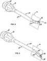
Figure 4 , there is shown analternative embodiment 50 in accordance with the present invention with common reference characters indicating substantially similar or identical elements of the invention as hereinabove described in connection with the embodiment shown inFigure 1 . - The
multipurpose phacoemulsification needle 50 includes a curved portion 52 adjacent to thetip portion 20 having acurvature 54 in aplane 56 not including the flat surface 26, seeFigure 2 . Preferably, the flat surface 26 is perpendicular to theplane 56 established by the curved portion curvature, or arc, 54. - In the
embodiment 50, a flat surface 26 faces inwardly from thearc 54 established by the needle body curved portion 52. - With reference to
Figure 5 , there is shown yet another embodiment 60 of a multipurpose phacoemulsification needle in accordance with the present invention with common reference numbers representing identical or substantially similar elements as hereinabove discussed in connection withFigures 1 and4 . - The phacoemulsification needle 60 is similar to the
embodiment 50 shown inFigure 4 except that acurved portion 62 is provided proximate thetip 20 which establishes anarc 64 opposite thearc 54 shown inFigure 4 and in which theflat surface 64 faces outwardly from thearc 64 established by the needle body curvedportion 62. - As hereinabove noted, these various phacoemulsification needle embodiments have the additional advantage in the generation of cavitational energy, manipulating tissue within the eye during surgery, as hereinabove noted, and accessing cortex material from difficult to access locations within the eye during irrigation and aspiration. The angle of curvature, or arc, 54, 64 may vary in the angle of the curvature or arc, the curvature depending upon the specific use intended for the
needle 50, 60. Figure 6 . illustrates amulti-purpose phacoemulsification needle 100 having aneedle body 102. Theneedle body 102 may, for example, be straight, like the needle body illustrated inFigure 1 , curved like the needle body illustrated inFigure 4 , or some other shape suitable for an ocular surgical procedure. Theneedle body 102 is disposed about acenterline 104 and comprises alumen 108 therein. Thecenterline 104 may be straight, as shown inFigure 6 , or may have at least a distal portion that is curved (e.g., like thearcs Figures 4 and 5 , respectively). Theneedle 100 further comprises a proximal end (not shown) and adistal tip 112. The proximal end is configured for attachment to a phacoemulsification handpiece. Thedistal tip 112 comprises aflat surface 114 disposed at an acute angle θ relative to a portion of thecenterline 104 intersected by aline 116 passing through theflat surface 114. Thedistal tip 112 further comprises an opening orport 118 disposed within theflat surface 114 and communicating with theneedle body lumen 108. Thedistal tip 112 includes acontinuous surface 120 that is free of discontinuities and extending from adistal portion 122 of thelumen 108 to adistal portion 123 of theneedle body 102. Preferably, thecontinuous surface 120 smoothly blends into arounded surface 124 generally disposed and having sufficient area for polishing the lens capsule of an eye.- As used herein, the term discontinuity refers to a transition between two surfaces or surface portions that produce a visible corner or edge. While all physical corners and edges ultimately have a radius, a discontinuity, as it is used herein, pertains to a corner or edge that is visible as a discrete feature. As used in this context, "visible" refers to visible as seen by the naked eye, or with the assistance of certain low-power magnification devices, such as an ocular or a loupe. Another way of defining a discontinuity, as used herein, is as a portion or feature of surface at the distal tip of a phacoemulsification needle that has a sharp edge or a radius sufficiently small to initiate or propagate a tear in the wall of a lens capsule of a human eye when the capsule is invaginated by the needle under typical ocular surgical aspiration conditions.
- The angle θ of the
flat surface 114, combined with the inclusion of therounded surface 124, allow themulti-purpose phacoemulsification needle 100 to be used advantageously in both phacoemulsification procedures and I/A procedures in which phacoemulsification power either is not supplied to theneedle 100, or is supplied only for short periods of time, for example, on an as-needed bases to break apart lens material that causes the aspiration flow to become temporarily blocked or occluded. Preferably, theflat surface 114 is disposed at an angle of about 45° degrees (e.g., to within typical engineering tolerance). In some embodiments, the flat surface 26 is disposed at an angle of between about 25 degrees and 65 degrees, preferably between 35 degrees and 55 degrees. In other embodiments, theflat surface 114 is replaced by or combined with a concave or some other arcuate surface that is configured to help focus phacoemulsification power to a predetermined location in front of and/or above theneedle 100. The singleflat surface 114 may also be replaced by two or more surface portions that are either flat or arcuate and that are disposed at different angles relative to thecenterline 104. - The
continuous surface 120 enhances the versatility of themulti-purpose phacoemulsification needle 100 by, for example, allowing the surgeon to advantageously perform a variety of techniques with a single handpiece. For example, during some surgical procedures, instead of using therounded surface 124, a surgeon may prefer to break apart or emulsify relatively soft and/or sticky cortical material remaining on the capsule surface by invaginating the capsule surface inside theneedle 100. As with theneedle 100, inner and outer surfaces of thedistal tip 212 ofphacoemulsification needle 200 are preferably configured to be smooth and free of any sharp edges or corners in order to protect the capsule surface from tearing during invagination. - Referring to
Figures 7-9 , in certain embodiments, amulti-purpose phacoemulsification needle 200 is provided that is similar to theneedle 100, with the additional feature that theneedle 200 comprises aninternal cavity 201 that is advantageously configured to enhance the ability of the needle to emulsify cataract and cortical lens material when a lens capsule is invaginated within theneedle 200. Theneedle body 202 is disposed about acenterline 204 and includes alumen 208 therein that has a cross-sectional area A1 in a direction normal to thecenterline 204. Theneedle 200 further comprises aneedle body 202 and adistal tip 212 comprising anarcuate surface 214 and aface 216 with an opening orport 218 therein. - Both the
internal cavity 201 and the external portions of thedistal tip 212 are configured to advantageously avoid tearing of the lens capsule during invagination thereof. - The
port 218 has a cross-sectional area A2 in a plane generally parallel to theface 216 and is in fluid communication with theinternal cavity 201. Theinternal cavity 201 has a cross-sectional area A3 normal to thecenterline 204 and is in fluid communication with thelumen 208. Preferably, the cross-sectional area A3 of theinternal cavity 201 is greater than both the cross-sectional area A1 of thelumen 208 and the cross-sectional area A2 of theport 218. In some embodiments not constituting a portion of the invention, the cross-sectional area A2 of theport 218 may be equal to the cross-sectional area A3 of theinternal cavity 201. - The generally larger dimension of the
internal cavity 201 advantageously provides a cavity volume into which a section of the natural lens or an invaginated portion of the lens capsule may be drawn in by aspiration. In addition, the large dimension or size of theinternal cavity 201 advantageously helps to provide a relatively large surface area for transmitting phacoemulsification power that may be used to emulsify cortical material still attached to the capsule wall. Because of the relatively large surface area, phacoemulsification power may be applied over a very short period of time to emulsify the cortical material, thus reducing the total amount of phacoemulsification energy necessary in performing this task. - As shown in the illustrated embodiment, the cross-sectional area A2 of the
port 218 may be greater than the cross-sectional area A1 of thelumen 208. In such embodiments, the area A1 of thelumen 208 may be selected to restrict the aspiration flow rate to a predetermined value in order to protect the eye. The area A2 of theport 218 may, therefore, be sized independent of aspiration restriction requirements. For example the area A2 and/or the shape of theport 218 may be selected as a parameter in determining the size and/or shape of the portion of the lens capsule to be invaginated. Additionally or alternatively, the size and shape of theinternal cavity 201 and/or the size and shape of theport 218 may be combined with periodic or occasional use of phacoemulsification power to theneedle 200 to favorably break apart or emulsify pieces of the lens material that have a predetermined, characteristic dimension and/or shape. - The
ports Figure 8 . In general, theports ports Figure 8 , or elliptical or oval in shape. Alternatively, theports ports - In certain embodiments, for example when needles 100, 200 are configured to be an aspiration flow restrictor, the
ports ports - In the illustrated embodiment, the
distal tip 212 is straight and comprises a rounded bottom portion having a surface area configured for polishing an eye lens capsule. In other embodiments, thedistal tip 212 curved and is disposed about a curved portion of thecenterline 204. - The
face 216 of thedistal tip 212 is disposed from a location near thecenterline 204 to a location at adistal end 223 of theneedle body 202. Thedistal face 216 is preferably disposed at an angle relative to thecenterline 204 in the vicinity thereof. In some embodiments, thedistal face 216 is disposed at an angle of about 45° degrees (e.g., to within typical engineering tolerance). In other embodiments, thedistal face 216 is disposed at an angle of between about 25 degrees and 65 degrees, preferably between 35 degrees and 55 degrees. Thedistal face 216 may be flat, as illustrated inFigure 7 or may be concave (e.g., curved in at least one axis) or some other arcuate shape, for example, to help focus phacoemulsification power to a predetermined location in front of and/or above theneedle 200. - The
internal cavity 201 preferably comprises aproximal face 226, generally facing towards theport 218, and adistal face 228, generally facing toward thelumen 208. The faces 226, 228 are configured to direct phacoemulsification energy into theinternal cavity 201, thus surrounding and concentrating phacoemulsification energy towards any cortical or other lens material contained inside thecavity 201. This configuration allows theneedle 200 to emulsify lens material with a reduced amount of phacoemulsification energy. In some embodiments, thefaces cavity 201 and/or thecenterline 204. Alternatively, at least portions of one or both of thefaces cavity 201. In certain embodiments, thefaces - Referring to
Figure 10 , in certain embodiments, amulti-purpose phacoemulsification needle 300 comprises aneedle body 302 and a distal tip 312. Theneedle 300 is substantially the same as theneedle 200, except that the distal tip 312 has anouter diameter 380 that is greater than anouter diameter 382 of theneedle body 302. Thesmaller diameter 382 may be selected, for example, to reduce the trauma to eye. - Referring to
Figures 11 and 12 , in certain embodiments, amulti-purpose phacoemulsification needle 400 comprises aneedle body 402, abody lumen 408, and adistal tip 412. Theneedle 400 is substantially the same theneedle 200, except that is comprises aproximal lumen 409 that is disposed proximal to and coaxial with thebody lumen 408. Theproximal lumen 409 has a cross-sectional area A4 that is greater than a cross-sectional area A5 of thebody lumen 408. The cross-sectional areas A4, A5 shown inFigure 12 are circular in form; however, either or both of the areas A4, A5 may be configured to have any convenient shape, including oval, square, rectangular, or starred. The smaller cross-sectional area A5 may be used as a flow restrictor, while the larger cross-sectional area A4 may be advantageously utilized to help prevent theneedle 400 from becoming clogged by aspirated lens material. Theneedle body lumen 402 has a longitudinal length L, which preferably is greater than or equal to an outer diameter of theneedle body 402. - Referring to
Figures 13-15 , amulti-purpose phacoemulsification needle 500 comprises aneedle body 502 disposed about acenterline 504, abody lumen 508 disposed within theneedle body 502, and adistal tip 512. Theneedle 500 is substantially the same theneedle 400, except that thebody lumen 508 comprises a plurality offins 550 having isolated distal ends 552. Thebody lumen 508 comprises aprimary surface 554 having a diameter D1. Thefins 550 protrude inwardly from thesurface 554 and preferably toward thecenterline 504. - The
fins 550 may be configured to havedistal faces 556 that are combined to form part of aninternal cavity 501 having similar properties to theinternal cavity 201 described in greater detail above herein. Each ofdistal faces 556 may be disposed perpendicular to or at an angle to thecenterline 504. At least portions of thedistal faces 556 may be flat in one axis or in two perpendicular axes. Alternatively or additionally, at least a portion of some or all of thedistal faces 556 may be curved or otherwise configured in at least one axis, for example, in order to focus phacoemulsification power toward one or more volumes, for example, a volume disposed at or near thecenterline 504. - The isolated distal ends 552 of the
fins 550 in the illustrated embodiment shown inFigure 15 are flat surfaces disposed about thecenterline 504. In general, the isolated distal ends 552 may have any configuration or shape suitable for a particular set of design parameters. For example, the isolated distal ends 552 may be in the form of an arcuate surface and/or may be disposed at a different distances from thecenterline 504. In addition, at least one of the distal ends 552 may have a shape or form that is different from that of the other distal ends 552. The isolated distal ends 552 are preferably configured such that acircle 558 passing through theends 552 of thefins 550 has a diameter D2 that is less than the diameter D1 of theprimary surface 554. In some embodiments, the isolated distal ends 552 are configured such that the diameter D2 of thecircle 558 is less than 80 percent of the diameter D1 of theprimary surface 554 of thebody lumen 508, preferably less than 50 percent of the diameter D1, and in some cases less than 25 percent of the diameter D1. - The
phacoemulsification needle 500 further comprises aport 518 similar to theports port 518 may be configured to have a cross-sectional area that is less than the area of thecircle 558 and/or less than the effective cross-sectional area of thebody lumen 508, for example, when theport 518 is configured to be an aspiration flow restrictor. Alternatively, cross-sectional area of theport 518 may be selected to be greater than the effective cross-sectional area of thebody lumen 508, for example, when thebody lumen 508 is configured to be an aspiration flow restrictor. - The
fins 550 are preferably structured to help tear or emulsify lens material passing thereover. To aid in this process, thebody lumen 508 may comprise at least threefins 550, preferably at least fivefins 550 to as many as eight ormore fins 550.Voids 560 betweenadjacent fins 550 provide an effective cross-sectional area of thebody lumen 508 that is greater than the cross-sectional area of thecircle 558. Thevoids 560 may thereby be used to provide greater aspiration flow rates through theneedle 500, especially when theneedle 500 becomes totally or partially occluded. In addition, thevoids 560 may be used to increase or otherwise control the cross-sectional area of thelumen 508. - The
multi-purpose phacoemulsification needle 500 may further comprises aproximal lumen 509 that is disposed adjacent and proximal to theneedle body lumen 408. In such embodiments, thefins 550 are preferably sufficiently rigid to prevent deformation thereof as aspirated fluid and other material passes over thefins 550. For example, thefins 550 may each have a longitudinal extent along thecenterline 504 that is greater than the diameter D1 of thebody lumen 508, preferably greater than a cross-sectional diameter of thelumen body 508. - Referring to
Figure 16 , in certain embodiments, one of the multi-purpose phacoemulsification needles 100, 200, 300, 400, 500, or some variant thereof, are used in amethod 600 of removing the natural lens of an eye. Themethod 600 comprises anoperational block 602, providing a multi-purpose phacoemulsification needle according to an embodiment of the present invention. Themethod 600 further comprises anoperational block 604, applying phacoemulsification power to a distal tip of the needle and removing at least a portion of the natural lens contained within the lens capsule of the eye. Themethod 600 also comprises anoperational block 606, removing phacoemulsification power and passing a face of the distal tip of the needle over the surface of the lens capsule so as to remove cortical material therefrom. Themethod 600 additionally comprises anoperational block 608, invaginating a portion of the lens capsule within the inner cavity. Themethod 600 also comprises anoperational block 610, reapplying phacoemulsification power while capsule portion is invaginated. - Although there has been hereinabove described a specific curved multi-purpose phacoemulsification needle in accordance with the present invention for the purpose of illustrating the manner in which the invention may be used to advantage, it should be appreciated that the invention is not limited thereto. That is, the present invention may suitably comprise, consist of, or consist essentially of the recited elements. Further, the invention illustratively disclosed herein suitably may be practiced in the absence of any element which is not specifically disclosed herein.
Claims (12)
- A multi-purpose phacoemulsification needle (10; 50; 60; 100; 200; 300; 400; 500), comprising:a needle body (12; 102; 202; 302; 402; 502) disposed about a centerline (30; 104; 204) and having a lumen (14; 108; 308; 408) 508) disposed therein, the lumen having a first cross-sectional area (A1) normal to the centerline;a proximal end (16) adapted for attachment to a phacoemulsification handpiece; anda distal tip (20; 112; 212; 312; 412; 512) comprising an arcuate surface (24; 124; 214) and a face (26; 114; 216) with a port (38; 118; 218) therein, the port having a second cross-sectional area (A2) in a plane generally parallel to the face and being in fluid communication with an internal cavity (201) and the needle body lumen, the internal cavity having a third cross-sectional area (A3) normal to the centerline and being in fluid communication with the lumen;the internal cavity comprising a surface portion disposed about the port (38; 118), the distal tip comprising a continuous surface (120) free of discontinuities that includes the surface portion and a distal portion of the needle body;the third cross-sectional area (A3) being greater than the first cross-sectional area (A1) and greater than the second cross-sectional area (A2), wherein the distal tip further comprises:a flat surface disposed at an acute angle relative to the centerline; the port being disposed within the flat surface ; a continuous surface free of discontinuities comprising the flat surface, a distal portion of the lumen, and a distal portion of the needle body.
- The multi-purpose phacoemulsification needle of claim 1, wherein the second cross-sectional area (A2) is greater than the first cross-sectional area (A1).
- The multi-purpose phacoemulsification needle of claim 1, wherein the port has an effective diameter that is less than about 0.5 mm, and preferably between about 0.2 mm and about 0.4 mm.
- The multi-purpose phacoemulsification needle of claim 1, wherein the cavity is configured to emulsify cortical material when at least a portion of a lens capsule is invaginated within the cavity.
- The multi-purpose phacoemulsification needle of claim 1, wherein the internal cavity (201) comprises a distal face (228) that is disposed at an angle to the centerline (204).
- The multi-purpose phacoemulsification needle of claim 1, wherein said angle is between about 25 degrees and 65 degrees, preferably between 35 degrees and 55 degrees and more preferably about 45 degrees.
- The multi-purpose phacoemulsification needle of claim 5, wherein the distal face (228) is either flat or curved in at least one axis.
- The multi-purpose phacoemulsification needle of claim 5, wherein the distal face (228) is configured to focus phacoemulsification power toward a volume disposed about the centerline.
- The multi-purpose phacoemulsification needle of claim 1, wherein the distal tip further comprises:a rounded bottom portion having a surface area configured for polishing an eye lens capsule; and a top portion comprising a flat surface disposed from a location at or near the centerline to a location at a distal end of the needle body.
- The multi-purpose phacoemulsification needle of claim 1, wherein the distal tip has an outer diameter that is greater than an outer diameter of the needle body.
- The multi-purpose phacoemulsification needle of claim 1, further comprising a proximal lumen proximal to and coaxial with needle body lumen, the proximal lumen having a cross-sectional area that is greater than the first cross-sectional area of the needle body lumen.
- The multi-purpose phacoemulsification needle of claim 1, wherein needle body lumen has a longitudinal length that is greater than an outer diameter of the needle body.
Priority Applications (1)
| Application Number | Priority Date | Filing Date | Title |
|---|---|---|---|
| EP17197506.3AEP3300705B1 (en) | 2006-05-02 | 2007-05-01 | Multi-purpose phacoemulsification needle |
Applications Claiming Priority (2)
| Application Number | Priority Date | Filing Date | Title |
|---|---|---|---|
| US11/416,937US8287484B2 (en) | 2006-05-02 | 2006-05-02 | Multi-purpose phacoemulsification needle |
| PCT/US2007/067918WO2007130965A2 (en) | 2006-05-02 | 2007-05-01 | Multi-purpose phacoemulsification needle |
Related Child Applications (1)
| Application Number | Title | Priority Date | Filing Date |
|---|---|---|---|
| EP17197506.3ADivisionEP3300705B1 (en) | 2006-05-02 | 2007-05-01 | Multi-purpose phacoemulsification needle |
Publications (2)
| Publication Number | Publication Date |
|---|---|
| EP2012723A2 EP2012723A2 (en) | 2009-01-14 |
| EP2012723B1true EP2012723B1 (en) | 2017-11-08 |
Family
ID=38472917
Family Applications (2)
| Application Number | Title | Priority Date | Filing Date |
|---|---|---|---|
| EP17197506.3AActiveEP3300705B1 (en) | 2006-05-02 | 2007-05-01 | Multi-purpose phacoemulsification needle |
| EP07761669.6ANot-in-forceEP2012723B1 (en) | 2006-05-02 | 2007-05-01 | Multi-purpose phacoemulsification needle |
Family Applications Before (1)
| Application Number | Title | Priority Date | Filing Date |
|---|---|---|---|
| EP17197506.3AActiveEP3300705B1 (en) | 2006-05-02 | 2007-05-01 | Multi-purpose phacoemulsification needle |
Country Status (5)
| Country | Link |
|---|---|
| US (2) | US8287484B2 (en) |
| EP (2) | EP3300705B1 (en) |
| AU (1) | AU2007248163B2 (en) |
| CA (2) | CA2944944C (en) |
| WO (1) | WO2007130965A2 (en) |
Families Citing this family (24)
| Publication number | Priority date | Publication date | Assignee | Title |
|---|---|---|---|---|
| US20070142791A1 (en)* | 2003-05-07 | 2007-06-21 | Aleeve Medical Inc. A Delaware Corporation | U-shaped disc shunt and delivery device |
| AU2008347598B2 (en)* | 2008-01-15 | 2013-05-09 | Ao Technology Ag | Cannula and device for liquid jet irrigation of bone |
| US20110092885A1 (en)* | 2008-08-27 | 2011-04-21 | Teruyuki Myoshi | Phacoemulsification Needle Tip With Bumps |
| WO2010022460A1 (en)* | 2008-09-01 | 2010-03-04 | Nigel Morlet | Cutting needle tip for surgical instrument |
| US8992459B2 (en)* | 2009-02-13 | 2015-03-31 | Art, Limited | Apparatus and method for phacoemulsification |
| EP2552330B1 (en) | 2010-03-29 | 2015-05-27 | Nigel Morlet | Improved needle tip for surgical instrument |
| WO2013016772A1 (en) | 2011-08-03 | 2013-02-07 | Nigel Morlet | Grooved needle tip for surgical instrument |
| US9289575B2 (en)* | 2013-06-20 | 2016-03-22 | Philip J. Dye | Catheter |
| US9878125B2 (en) | 2013-06-20 | 2018-01-30 | Zcath Llc | Intermittent urinary catheter |
| US9486603B2 (en) | 2013-06-20 | 2016-11-08 | Philip J. Dye | Intermittent urinary catheter |
| AR098613A1 (en) | 2013-12-06 | 2016-06-01 | Genentech Inc | APPLIANCES AND METHODS FOR THE ADMINISTRATION OF MEDICINES IN LOW VOLUMES |
| ES2546810B1 (en)* | 2014-03-27 | 2016-09-27 | Jose Luis RODRIGUEZ PRATS | POINT OF FACOFRAGMENTATION AND FACOASPIRATION |
| US11033428B2 (en)* | 2015-05-26 | 2021-06-15 | William F. WILEY | Phacoemulsification tip |
| US20170119974A1 (en)* | 2015-11-04 | 2017-05-04 | Custom Medical Applications, Inc. | Needles and related assemblies and methods |
| US10624785B2 (en) | 2016-01-30 | 2020-04-21 | Carl Zeiss Meditec Cataract Technology Inc. | Devices and methods for ocular surgery |
| US11278450B2 (en) | 2017-05-04 | 2022-03-22 | Carl Zeiss Meditec Cataract Technology Inc. | Devices and methods for ocular surgery |
| KR102782862B1 (en) | 2018-06-05 | 2025-03-19 | 칼 짜이스 메디텍 캐터랙트 테크놀로지 인크. | Ophthalmic Microsurgical Instruments, Systems and Methods of Use |
| JP7434340B2 (en) | 2019-02-01 | 2024-02-20 | カール・ツァイス・メディテック・キャタラクト・テクノロジー・インコーポレイテッド | Ophthalmic cutting instrument with integrated suction pump |
| USD910168S1 (en)* | 2019-05-14 | 2021-02-09 | Johnson & Johnson Surgical Vision, Inc. | High torque surgical needle hub |
| KR20220010739A (en) | 2019-05-17 | 2022-01-26 | 칼 짜이스 메디텍 캐터랙트 테크놀로지 인크. | Ophthalmic Cutting Instrument with Integral Suction Pump |
| CA3142864A1 (en) | 2019-06-07 | 2020-12-10 | Carl Zeiss Meditec Cataract Technology Inc. | Multi-stage trigger for ophthalmology cutting tool |
| US20220370246A1 (en)* | 2019-10-24 | 2022-11-24 | Art, Limited | Apparatus and method for phacoemulsification |
| JP7652887B2 (en)* | 2020-08-14 | 2025-03-27 | ジャイラス エーシーエムアイ インク ディー/ビー/エー オリンパス サージカル テクノロジーズ アメリカ | Interchangeable probe tips for lithotripsy |
| WO2025181581A1 (en)* | 2024-02-29 | 2025-09-04 | Alcon Inc. | Devices and methods for improved removal of cortical material |
Family Cites Families (54)
| Publication number | Priority date | Publication date | Assignee | Title |
|---|---|---|---|---|
| US3732858A (en) | 1968-09-16 | 1973-05-15 | Surgical Design Corp | Apparatus for removing blood clots, cataracts and other objects from the eye |
| US3844272A (en) | 1969-02-14 | 1974-10-29 | A Banko | Surgical instruments |
| US4047532A (en) | 1975-04-21 | 1977-09-13 | Phillips Jack L | Vacuum forcep and method of using same |
| US4531943A (en) | 1983-08-08 | 1985-07-30 | Angiomedics Corporation | Catheter with soft deformable tip |
| US4689040A (en) | 1985-04-29 | 1987-08-25 | Thompson Robert J | Tip for a phacoemulsification needle |
| US4816018A (en) | 1985-08-02 | 1989-03-28 | Ultramed Corporation | Ultrasonic probe tip |
| US4808170A (en) | 1985-12-16 | 1989-02-28 | Alcon Laboratories, Inc. | Hypotraumatic injection needle useful in ophthalmic surgery |
| US4808153A (en) | 1986-11-17 | 1989-02-28 | Ultramed Corporation | Device for removing plaque from arteries |
| US5112339A (en)* | 1990-06-18 | 1992-05-12 | Ophthalmocare, Inc. | Apparatus for extracting cataractous tissue |
| US4869715A (en) | 1988-04-21 | 1989-09-26 | Sherburne Fred S | Ultrasonic cone and method of construction |
| JPH0532094Y2 (en)* | 1988-05-17 | 1993-08-18 | ||
| US5154694A (en) | 1989-06-06 | 1992-10-13 | Kelman Charles D | Tissue scraper device for medical use |
| US4959049A (en) | 1989-09-11 | 1990-09-25 | Smirmaul Heinz J | Tip for a phacoemulsification needle |
| US5295980A (en) | 1989-10-30 | 1994-03-22 | Ersek Robert A | Multi-use cannula system |
| US5084009A (en) | 1990-04-18 | 1992-01-28 | Mackool Richard J | Fluid infusion sleeve for use during eye surgery |
| US5515871A (en) | 1990-09-28 | 1996-05-14 | Sulzer Brothers Ltd. | Hollow needle for medical use and a laser method for manufacturing |
| US5100390A (en) | 1990-10-22 | 1992-03-31 | Norma A. Lubeck | Lubeck spinal catheter needle |
| US5290267A (en) | 1991-01-17 | 1994-03-01 | Fresenius Ag | Hypodermic needle |
| US5242385A (en) | 1991-10-08 | 1993-09-07 | Surgical Design Corporation | Ultrasonic handpiece |
| US5213569A (en)* | 1992-03-31 | 1993-05-25 | Davis Peter L | Tip for a tissue phacoemulsification device |
| US5254106A (en) | 1992-04-17 | 1993-10-19 | Feaster Fred T | Hydrodissection needle |
| US5437678A (en) | 1992-11-30 | 1995-08-01 | Neomedix Corporation | Ophthalmic lens removal method and apparatus |
| US5286256A (en) | 1992-12-30 | 1994-02-15 | Mackool Richard J | Fluid infusion sleeve |
| AU4055793A (en) | 1993-03-31 | 1994-10-24 | Peter L. Davis | Phacoemulsification method and tip |
| DE4313245C2 (en) | 1993-04-23 | 1997-03-27 | Geuder Hans Gmbh | Hollow needle for an ophthalmic surgical instrument |
| US5464389A (en) | 1993-08-10 | 1995-11-07 | Stahl; Norman O. | Working tip for fragmenting and aspirating ocular tissue |
| US5484398A (en) | 1994-03-17 | 1996-01-16 | Valleylab Inc. | Methods of making and using ultrasonic handpiece |
| ATE497747T1 (en)* | 1994-09-02 | 2011-02-15 | Oversby Pty Ltd | PHACO EMULSIFICATION NEEDLE WITH NOTCHES |
| WO1996038091A1 (en) | 1995-06-02 | 1996-12-05 | Surgical Design Corporation | Phacoemulsification handpiece, sleeve, and tip |
| US5755700A (en) | 1995-07-27 | 1998-05-26 | Michiel S. Kritzinger | Corneal irrigation cannula and method of using |
| US5836926A (en) | 1996-05-13 | 1998-11-17 | Schneider (Usa) Inc | Intravascular catheter |
| US5697898A (en)* | 1996-05-31 | 1997-12-16 | Surgical Design Corporation | Automated free flow mechanism for use in phacoemulsification, irrigation and aspiration of the eye |
| US5746713A (en) | 1996-06-06 | 1998-05-05 | Hood; Larry | Phacoemulsification needle |
| US5788679A (en) | 1996-06-26 | 1998-08-04 | Gravlee, Jr.; Joseph F. | Phacoemulsification needle |
| DE19628252A1 (en)* | 1996-07-12 | 1998-01-15 | Jochen Dr Med Kammann | Probe for removal of eye tissue |
| US5733266A (en) | 1996-07-26 | 1998-03-31 | Gravlee, Jr.; Joseph F. | Hypodermic needle |
| WO1998023212A1 (en) | 1996-11-27 | 1998-06-04 | Armand Maaskamp | Needle for surgical use |
| US5871470A (en) | 1997-04-18 | 1999-02-16 | Becton Dickinson And Company | Combined spinal epidural needle set |
| US5980529A (en) | 1997-09-17 | 1999-11-09 | Vidda, Inc. | Work tip for surgical ultrasonic device |
| US5993408A (en) | 1997-10-03 | 1999-11-30 | Allergan Sales, Inc. | Thin tip phaco needle |
| US6039715A (en) | 1998-05-11 | 2000-03-21 | Mackool; Richard J. | Angulated phacoemulsification needle whose outer surface converges and inner channel narrows |
| US6398759B1 (en)* | 1998-06-04 | 2002-06-04 | Alcon Manufacturing, Ltd. | Liquefracture handpiece tip |
| US6402734B1 (en) | 1998-07-02 | 2002-06-11 | Jeffrey N. Weiss | Apparatus and method for cannulating retinal blood vessels |
| US6398754B1 (en) | 1998-09-30 | 2002-06-04 | Allergan, Inc. | Phaco tip with fluid bypass port |
| EP1129681A1 (en) | 2000-03-01 | 2001-09-05 | Optikon 2000 S.p.a. | Phacoemulsification tip |
| US6491670B1 (en) | 2000-04-04 | 2002-12-10 | Duke University | Miniaturized surgical instruments especially useful for the opthalmologic surgical procedures and methods of making the same |
| IT249046Y1 (en) | 2000-12-11 | 2003-03-25 | Optikon 2000 Spa | EMULSIFIED TIP FOR OCULISTIC SURGERY, IN PARTICULAR FOR THE PHACOEMULSIFICATION OF CATARACT. |
| US6554809B2 (en) | 2001-08-02 | 2003-04-29 | Teodulo Aves | Epidural catheter needle |
| US7037296B2 (en) | 2002-04-04 | 2006-05-02 | Advanced Medical Optics, Inc. | Curved multi-purpose phacoemulsification needle |
| ES2257731T3 (en) | 2003-04-04 | 2006-08-01 | Takayuki Akahoshi | PHACOEMULSION NEEDLE. |
| US20040199192A1 (en) | 2003-04-04 | 2004-10-07 | Takayuki Akahoshi | Phacoemulsification needle |
| US7588553B2 (en)* | 2004-09-07 | 2009-09-15 | Dewey Steven H | Phacoemulsification device having rounded edges |
| US20060217739A1 (en)* | 2005-03-22 | 2006-09-28 | Alcon, Inc. | Phacoemulsification tip |
| US20080058708A1 (en)* | 2005-08-02 | 2008-03-06 | Takayuki Akahoshi | Phacoemulsification Needle |
- 2006
- 2006-05-02USUS11/416,937patent/US8287484B2/ennot_activeExpired - Fee Related
- 2007
- 2007-05-01AUAU2007248163Apatent/AU2007248163B2/ennot_activeCeased
- 2007-05-01EPEP17197506.3Apatent/EP3300705B1/enactiveActive
- 2007-05-01CACA2944944Apatent/CA2944944C/ennot_activeExpired - Fee Related
- 2007-05-01EPEP07761669.6Apatent/EP2012723B1/ennot_activeNot-in-force
- 2007-05-01CACA2651112Apatent/CA2651112C/ennot_activeExpired - Fee Related
- 2007-05-01WOPCT/US2007/067918patent/WO2007130965A2/enactiveApplication Filing
- 2012
- 2012-09-21USUS13/624,060patent/US9649222B2/ennot_activeExpired - Fee Related
Non-Patent Citations (1)
| Title |
|---|
| None* |
Also Published As
| Publication number | Publication date |
|---|---|
| CA2651112C (en) | 2016-11-22 |
| EP2012723A2 (en) | 2009-01-14 |
| CA2944944C (en) | 2018-10-23 |
| EP3300705B1 (en) | 2019-06-26 |
| WO2007130965A2 (en) | 2007-11-15 |
| US20130018383A1 (en) | 2013-01-17 |
| CA2651112A1 (en) | 2007-11-15 |
| AU2007248163A1 (en) | 2007-11-15 |
| WO2007130965A3 (en) | 2008-02-07 |
| US8287484B2 (en) | 2012-10-16 |
| US20070260199A1 (en) | 2007-11-08 |
| US9649222B2 (en) | 2017-05-16 |
| CA2944944A1 (en) | 2007-11-15 |
| EP3300705A1 (en) | 2018-04-04 |
| AU2007248163B2 (en) | 2013-09-12 |
Similar Documents
| Publication | Publication Date | Title |
|---|---|---|
| EP2012723B1 (en) | Multi-purpose phacoemulsification needle | |
| EP2012722B1 (en) | Multi-purpose phacoemulsification needle | |
| US7037296B2 (en) | Curved multi-purpose phacoemulsification needle | |
| US5993408A (en) | Thin tip phaco needle | |
| US7014629B2 (en) | Tapered infusion sleeve portal | |
| US10449088B2 (en) | Apparatus and method for phacoemulsification | |
| US20110015561A1 (en) | Phacoemulsification Needle | |
| US20100010419A1 (en) | Phacoemulssification Needle Tips | |
| US6958056B2 (en) | Multi-purpose phacoemulsification needle | |
| US20090137971A1 (en) | Phacoemulsification Needle Tips for Torsional Motion | |
| US8439933B2 (en) | Double lumen phacoemulsification needle tip | |
| AU2004277872B2 (en) | Phacoemulsification needle | |
| JP2004358227A (en) | Phakoemulsifying needle | |
| US20220370246A1 (en) | Apparatus and method for phacoemulsification | |
| AU2015207866B2 (en) | Multi-purpose phacoemulsification needle | |
| AU2013201760B2 (en) | Multi-purpose phacoemulsification needle | |
| US20110046541A1 (en) | Phacoemulsification Needle Tip with Interior Step | |
| US20250241792A1 (en) | Phacoemulsification instruments | |
| US20240108504A1 (en) | Needle for attachment to ophthalmic surgical handpieces | |
| EP1765431A1 (en) | Tapered infusion sleeve portal |
Legal Events
| Date | Code | Title | Description |
|---|---|---|---|
| PUAI | Public reference made under article 153(3) epc to a published international application that has entered the european phase | Free format text:ORIGINAL CODE: 0009012 | |
| 17P | Request for examination filed | Effective date:20081031 | |
| AK | Designated contracting states | Kind code of ref document:A2 Designated state(s):AT BE BG CH CY CZ DE DK EE ES FI FR GB GR HU IE IS IT LI LT LU LV MC MT NL PL PT RO SE SI SK TR | |
| AX | Request for extension of the european patent | Extension state:AL BA HR MK RS | |
| DAX | Request for extension of the european patent (deleted) | ||
| RAP1 | Party data changed (applicant data changed or rights of an application transferred) | Owner name:ABBOTT MEDICAL OPTICS INC. | |
| RAP1 | Party data changed (applicant data changed or rights of an application transferred) | Owner name:ABBOTT MEDICAL OPTICS INC. | |
| 17Q | First examination report despatched | Effective date:20160311 | |
| GRAP | Despatch of communication of intention to grant a patent | Free format text:ORIGINAL CODE: EPIDOSNIGR1 | |
| INTG | Intention to grant announced | Effective date:20170526 | |
| GRAS | Grant fee paid | Free format text:ORIGINAL CODE: EPIDOSNIGR3 | |
| GRAA | (expected) grant | Free format text:ORIGINAL CODE: 0009210 | |
| AK | Designated contracting states | Kind code of ref document:B1 Designated state(s):AT BE BG CH CY CZ DE DK EE ES FI FR GB GR HU IE IS IT LI LT LU LV MC MT NL PL PT RO SE SI SK TR | |
| REG | Reference to a national code | Ref country code:GB Ref legal event code:FG4D | |
| REG | Reference to a national code | Ref country code:CH Ref legal event code:EP Ref country code:AT Ref legal event code:REF Ref document number:943438 Country of ref document:AT Kind code of ref document:T Effective date:20171115 | |
| REG | Reference to a national code | Ref country code:IE Ref legal event code:FG4D | |
| REG | Reference to a national code | Ref country code:DE Ref legal event code:R096 Ref document number:602007052970 Country of ref document:DE | |
| REG | Reference to a national code | Ref country code:NL Ref legal event code:FP | |
| REG | Reference to a national code | Ref country code:CH Ref legal event code:NV Representative=s name:E. BLUM AND CO. AG PATENT- UND MARKENANWAELTE , CH | |
| REG | Reference to a national code | Ref country code:LT Ref legal event code:MG4D | |
| REG | Reference to a national code | Ref country code:FR Ref legal event code:PLFP Year of fee payment:12 | |
| REG | Reference to a national code | Ref country code:AT Ref legal event code:MK05 Ref document number:943438 Country of ref document:AT Kind code of ref document:T Effective date:20171108 | |
| PG25 | Lapsed in a contracting state [announced via postgrant information from national office to epo] | Ref country code:ES Free format text:LAPSE BECAUSE OF FAILURE TO SUBMIT A TRANSLATION OF THE DESCRIPTION OR TO PAY THE FEE WITHIN THE PRESCRIBED TIME-LIMIT Effective date:20171108 Ref country code:LT Free format text:LAPSE BECAUSE OF FAILURE TO SUBMIT A TRANSLATION OF THE DESCRIPTION OR TO PAY THE FEE WITHIN THE PRESCRIBED TIME-LIMIT Effective date:20171108 Ref country code:SE Free format text:LAPSE BECAUSE OF FAILURE TO SUBMIT A TRANSLATION OF THE DESCRIPTION OR TO PAY THE FEE WITHIN THE PRESCRIBED TIME-LIMIT Effective date:20171108 Ref country code:FI Free format text:LAPSE BECAUSE OF FAILURE TO SUBMIT A TRANSLATION OF THE DESCRIPTION OR TO PAY THE FEE WITHIN THE PRESCRIBED TIME-LIMIT Effective date:20171108 | |
| PG25 | Lapsed in a contracting state [announced via postgrant information from national office to epo] | Ref country code:BG Free format text:LAPSE BECAUSE OF FAILURE TO SUBMIT A TRANSLATION OF THE DESCRIPTION OR TO PAY THE FEE WITHIN THE PRESCRIBED TIME-LIMIT Effective date:20180208 Ref country code:GR Free format text:LAPSE BECAUSE OF FAILURE TO SUBMIT A TRANSLATION OF THE DESCRIPTION OR TO PAY THE FEE WITHIN THE PRESCRIBED TIME-LIMIT Effective date:20180209 Ref country code:AT Free format text:LAPSE BECAUSE OF FAILURE TO SUBMIT A TRANSLATION OF THE DESCRIPTION OR TO PAY THE FEE WITHIN THE PRESCRIBED TIME-LIMIT Effective date:20171108 Ref country code:IS Free format text:LAPSE BECAUSE OF FAILURE TO SUBMIT A TRANSLATION OF THE DESCRIPTION OR TO PAY THE FEE WITHIN THE PRESCRIBED TIME-LIMIT Effective date:20180308 Ref country code:LV Free format text:LAPSE BECAUSE OF FAILURE TO SUBMIT A TRANSLATION OF THE DESCRIPTION OR TO PAY THE FEE WITHIN THE PRESCRIBED TIME-LIMIT Effective date:20171108 | |
| PG25 | Lapsed in a contracting state [announced via postgrant information from national office to epo] | Ref country code:DK Free format text:LAPSE BECAUSE OF FAILURE TO SUBMIT A TRANSLATION OF THE DESCRIPTION OR TO PAY THE FEE WITHIN THE PRESCRIBED TIME-LIMIT Effective date:20171108 Ref country code:CZ Free format text:LAPSE BECAUSE OF FAILURE TO SUBMIT A TRANSLATION OF THE DESCRIPTION OR TO PAY THE FEE WITHIN THE PRESCRIBED TIME-LIMIT Effective date:20171108 Ref country code:SK Free format text:LAPSE BECAUSE OF FAILURE TO SUBMIT A TRANSLATION OF THE DESCRIPTION OR TO PAY THE FEE WITHIN THE PRESCRIBED TIME-LIMIT Effective date:20171108 Ref country code:CY Free format text:LAPSE BECAUSE OF FAILURE TO SUBMIT A TRANSLATION OF THE DESCRIPTION OR TO PAY THE FEE WITHIN THE PRESCRIBED TIME-LIMIT Effective date:20171108 Ref country code:EE Free format text:LAPSE BECAUSE OF FAILURE TO SUBMIT A TRANSLATION OF THE DESCRIPTION OR TO PAY THE FEE WITHIN THE PRESCRIBED TIME-LIMIT Effective date:20171108 | |
| REG | Reference to a national code | Ref country code:DE Ref legal event code:R097 Ref document number:602007052970 Country of ref document:DE | |
| PG25 | Lapsed in a contracting state [announced via postgrant information from national office to epo] | Ref country code:PL Free format text:LAPSE BECAUSE OF FAILURE TO SUBMIT A TRANSLATION OF THE DESCRIPTION OR TO PAY THE FEE WITHIN THE PRESCRIBED TIME-LIMIT Effective date:20171108 Ref country code:RO Free format text:LAPSE BECAUSE OF FAILURE TO SUBMIT A TRANSLATION OF THE DESCRIPTION OR TO PAY THE FEE WITHIN THE PRESCRIBED TIME-LIMIT Effective date:20171108 Ref country code:IT Free format text:LAPSE BECAUSE OF FAILURE TO SUBMIT A TRANSLATION OF THE DESCRIPTION OR TO PAY THE FEE WITHIN THE PRESCRIBED TIME-LIMIT Effective date:20171108 | |
| RAP2 | Party data changed (patent owner data changed or rights of a patent transferred) | Owner name:JOHNSON & JOHNSON SURGICAL VISION, INC. | |
| PLBE | No opposition filed within time limit | Free format text:ORIGINAL CODE: 0009261 | |
| STAA | Information on the status of an ep patent application or granted ep patent | Free format text:STATUS: NO OPPOSITION FILED WITHIN TIME LIMIT | |
| 26N | No opposition filed | Effective date:20180809 | |
| PG25 | Lapsed in a contracting state [announced via postgrant information from national office to epo] | Ref country code:SI Free format text:LAPSE BECAUSE OF FAILURE TO SUBMIT A TRANSLATION OF THE DESCRIPTION OR TO PAY THE FEE WITHIN THE PRESCRIBED TIME-LIMIT Effective date:20171108 | |
| REG | Reference to a national code | Ref country code:CH Ref legal event code:PFA Owner name:JOHNSON AND JOHNSON SURGICAL VISION, INC., US Free format text:FORMER OWNER: ABBOTT MEDICAL OPTICS INC., US | |
| REG | Reference to a national code | Ref country code:DE Ref legal event code:R081 Ref document number:602007052970 Country of ref document:DE Owner name:JOHNSON & JOHNSON SURGICAL VISION, INC. (N. D., US Free format text:FORMER OWNER: ABBOTT MEDICAL OPTICS INC., SANTA ANA, CALIF., US | |
| REG | Reference to a national code | Ref country code:BE Ref legal event code:MM Effective date:20180531 Ref country code:NL Ref legal event code:HC Owner name:JOHNSON & JOHNSON SURGICAL VISION, INC.; US Free format text:DETAILS ASSIGNMENT: CHANGE OF OWNER(S), CHANGE OF OWNER(S) NAME; FORMER OWNER NAME: ABBOTT MEDICAL OPTICS INC. Effective date:20181204 | |
| PG25 | Lapsed in a contracting state [announced via postgrant information from national office to epo] | Ref country code:MC Free format text:LAPSE BECAUSE OF FAILURE TO SUBMIT A TRANSLATION OF THE DESCRIPTION OR TO PAY THE FEE WITHIN THE PRESCRIBED TIME-LIMIT Effective date:20171108 | |
| REG | Reference to a national code | Ref country code:IE Ref legal event code:MM4A | |
| PG25 | Lapsed in a contracting state [announced via postgrant information from national office to epo] | Ref country code:LU Free format text:LAPSE BECAUSE OF NON-PAYMENT OF DUE FEES Effective date:20180501 | |
| PG25 | Lapsed in a contracting state [announced via postgrant information from national office to epo] | Ref country code:IE Free format text:LAPSE BECAUSE OF NON-PAYMENT OF DUE FEES Effective date:20180501 | |
| PG25 | Lapsed in a contracting state [announced via postgrant information from national office to epo] | Ref country code:BE Free format text:LAPSE BECAUSE OF NON-PAYMENT OF DUE FEES Effective date:20180531 | |
| PGFP | Annual fee paid to national office [announced via postgrant information from national office to epo] | Ref country code:NL Payment date:20190412 Year of fee payment:13 | |
| PGFP | Annual fee paid to national office [announced via postgrant information from national office to epo] | Ref country code:DE Payment date:20190416 Year of fee payment:13 | |
| PGFP | Annual fee paid to national office [announced via postgrant information from national office to epo] | Ref country code:FR Payment date:20190410 Year of fee payment:13 | |
| PGFP | Annual fee paid to national office [announced via postgrant information from national office to epo] | Ref country code:CH Payment date:20190516 Year of fee payment:13 | |
| PGFP | Annual fee paid to national office [announced via postgrant information from national office to epo] | Ref country code:GB Payment date:20190501 Year of fee payment:13 | |
| PG25 | Lapsed in a contracting state [announced via postgrant information from national office to epo] | Ref country code:MT Free format text:LAPSE BECAUSE OF NON-PAYMENT OF DUE FEES Effective date:20180501 | |
| PG25 | Lapsed in a contracting state [announced via postgrant information from national office to epo] | Ref country code:TR Free format text:LAPSE BECAUSE OF FAILURE TO SUBMIT A TRANSLATION OF THE DESCRIPTION OR TO PAY THE FEE WITHIN THE PRESCRIBED TIME-LIMIT Effective date:20171108 | |
| PG25 | Lapsed in a contracting state [announced via postgrant information from national office to epo] | Ref country code:PT Free format text:LAPSE BECAUSE OF FAILURE TO SUBMIT A TRANSLATION OF THE DESCRIPTION OR TO PAY THE FEE WITHIN THE PRESCRIBED TIME-LIMIT Effective date:20171108 Ref country code:HU Free format text:LAPSE BECAUSE OF FAILURE TO SUBMIT A TRANSLATION OF THE DESCRIPTION OR TO PAY THE FEE WITHIN THE PRESCRIBED TIME-LIMIT; INVALID AB INITIO Effective date:20070501 | |
| REG | Reference to a national code | Ref country code:DE Ref legal event code:R119 Ref document number:602007052970 Country of ref document:DE | |
| REG | Reference to a national code | Ref country code:NL Ref legal event code:MM Effective date:20200601 | |
| PG25 | Lapsed in a contracting state [announced via postgrant information from national office to epo] | Ref country code:LI Free format text:LAPSE BECAUSE OF NON-PAYMENT OF DUE FEES Effective date:20200531 Ref country code:CH Free format text:LAPSE BECAUSE OF NON-PAYMENT OF DUE FEES Effective date:20200531 | |
| PG25 | Lapsed in a contracting state [announced via postgrant information from national office to epo] | Ref country code:NL Free format text:LAPSE BECAUSE OF NON-PAYMENT OF DUE FEES Effective date:20200601 | |
| GBPC | Gb: european patent ceased through non-payment of renewal fee | Effective date:20200501 | |
| PG25 | Lapsed in a contracting state [announced via postgrant information from national office to epo] | Ref country code:FR Free format text:LAPSE BECAUSE OF NON-PAYMENT OF DUE FEES Effective date:20200531 Ref country code:GB Free format text:LAPSE BECAUSE OF NON-PAYMENT OF DUE FEES Effective date:20200501 | |
| PG25 | Lapsed in a contracting state [announced via postgrant information from national office to epo] | Ref country code:DE Free format text:LAPSE BECAUSE OF NON-PAYMENT OF DUE FEES Effective date:20201201 |