EP2012695B1 - Electrosurgical cutting device - Google Patents
Electrosurgical cutting deviceDownload PDFInfo
- Publication number
- EP2012695B1 EP2012695B1EP07754304.9AEP07754304AEP2012695B1EP 2012695 B1EP2012695 B1EP 2012695B1EP 07754304 AEP07754304 AEP 07754304AEP 2012695 B1EP2012695 B1EP 2012695B1
- Authority
- EP
- European Patent Office
- Prior art keywords
- wires
- catheter
- electrosurgical
- distal
- distal end
- Prior art date
- Legal status (The legal status is an assumption and is not a legal conclusion. Google has not performed a legal analysis and makes no representation as to the accuracy of the status listed.)
- Active
Links
Images


Classifications
- A—HUMAN NECESSITIES
- A61—MEDICAL OR VETERINARY SCIENCE; HYGIENE
- A61B—DIAGNOSIS; SURGERY; IDENTIFICATION
- A61B18/00—Surgical instruments, devices or methods for transferring non-mechanical forms of energy to or from the body
- A61B18/04—Surgical instruments, devices or methods for transferring non-mechanical forms of energy to or from the body by heating
- A61B18/12—Surgical instruments, devices or methods for transferring non-mechanical forms of energy to or from the body by heating by passing a current through the tissue to be heated, e.g. high-frequency current
- A61B18/14—Probes or electrodes therefor
- A61B18/1492—Probes or electrodes therefor having a flexible, catheter-like structure, e.g. for heart ablation
Definitions
- the inventiongenerally relates to an electrosurgical cutting device for removal of portions of the mucuosa and/or submucosa tissue from the gastrointestinal tract of a human being.
- Diagnostic and therapeutic gastrointestinal endoscopyare commonly used to gain access to the digestive tract for the purpose of removing tissue.
- Common endoscopy proceduresinclude incision and ablation through various known mechanisms.
- Endoscopic mucosectomyalso known as endoscopic mucosal resection (EMR).
- EMRendoscopic mucosal resection
- Endoscopic mucosectomyinvolves the removal of a portion (i.e., resection) of the digestive wall including the mucosal membrane. This procedure typically removes a part or even all of the submucosa.
- Endoscopic mucosectomyis a curative endoscopic procedure which is intended for sessile benign tumors and intramucosal cancers. The procedure makes it possible to determine precisely the nature of any subsequent treatment that may be required.
- the incision devices currently utilized in endoscopic mucosectomymake tissue removal difficult. These problems are compounded by the thick gastrointestinal wall that the incisions are performed within. Considerable time and effort is therefore required by the physician to incise and remove the desired tissue. The inability to quickly incise tissue may increase patient trauma. Moreover, current incision devices cannot remove tissue in unfragmented portions. Assessment of fragmented tissue becomes increasingly difficult during sampling as compared to assessment of unfragmented tissue. Furthermore, fragmented resection of early cancers may lead to a higher rate of local tumor recurrence.
- a device according to the preamble of claim 1is known from WO1999US20045.
- the inventionis defined in claim 1.
- an electrosurgical cutting devicethat resolves or improves upon one or more of the above-described drawbacks.
- an electrosurgical cutting devicein a first aspect, includes a catheter and two or more electrically conductive wires extending through a lumen of the catheter.
- the wiresare movable between a retracted position and an extended cutting position.
- the wiresform a divergent configuration in the extended cutting position.
- An electrosurgical cutting devicecomprising a catheter, a plurality of electrically conductive resection wires disposed within a lumen of the catheter, and a handle assembly operably connected to a proximal end of the catheter is provided.
- Each of the plurality of resection wirescomprises a cutting portion.
- the electrosurgical cutting deviceis advanced towards a target region having tissue to be incised.
- Each of the plurality of resection wiresextend beyond the distal end of the catheter so as to form a divergent cutting configuration.
- Each of the plurality of resection wiresengages with the target region. Electrical current is applied to the cutting portion of each of the plurality of the resection wires.
- the handle assemblyis manipulated to incise the tissue of the target site and separate the tissue from underlying tissue.
- a method for electrosurgically incising tissueis disclosed.
- An endoscopeis maneuvered towards a target tissue site.
- An electrosurgical cutting devicewhich comprises a catheter, multiple electrically conductive cutting wires, and a handle assembly, is advanced into a working channel of an endoscope.
- the handle assemblyUpon reaching the target tissue site, the handle assembly is manipulated in order for the wires to transform from their compressed, retracted configuration to their divergent cutting configuration. Electrical current is applied to the wires to incise tissue from the target tissue site.
- FIG. 1is a side view showing the electrosurgical cutting device 100 in an extended cutting position.
- the electrosurgical cutting device 100includes a catheter 140 having a distal portion 170 and a proximal portion 171, a handle assembly 130 attached to the proximal portion 171 of the catheter 140, electrically conductive wires 110 and 120 extending through a lumen 160 of the catheter 140, and a hypodermic needle 180 movably disposed within the lumen 160 of the catheter 140.
- the catheter 140is configured for coupling to an electrosurgical generator 190.
- the electrosurgical generator 190is connected to an electrical port 191.
- the electrosurgical generator 190supplies the electrical energy to the wires 110 and 120 during the incision of tissue.
- the incision of the tissueis achieved by extending electrically conductive wires 110 and 120 by a predetermined distance S and angular separation ⁇ .
- the wires 110 and 120are movable between a retracted configuration and an extended configuration.
- the wires 110 and 120 in their extended configurationmay flare outwards as shown in Figure 1 .
- Many types of flared shapesare possible.
- the wires 110 and 120flare into a divergent configuration 500.
- the term "divergent" as described hereinrefers to the wires 110 and 120 separating a predetermined distance from each other in the extended cutting position for at least a portion therealong.
- Figures 1 and 3show the wires 110 and 120 in their extended cutting position with a V-shaped divergent configuration 500
- wires 110 and 120may have a U-shaped divergent configuration or an outward or inward curvature (not shown) near its distal end.
- the divergent configuration 500creates an excise area for receiving tissue within the configuration and/or along the edges of the configuration 500.
- Electrical current from the electrosurgical generator 190may be applied as the wires 110 and 120 extend outward into the divergent configuration 500 beyond the distal end 170 of the catheter 140. The current will heat the wires 110 and 120, thereby allowing the tissue to be incised by the wires 110 and 120.
- handle assembly 130includes a sliding member 193, a thumb ring 192, and a stem 177.
- the stem 177is fixedly attached to the catheter 140, and the sliding member 193 is fixedly attached to the proximal end of the wires 110 and 120.
- Sliding member 193is slidably connected to a stem 177, which is affixed to the proximal portion 171 of the catheter 140.
- Sliding member 193includes a pair of opposed finger rings 135 which enable a user to grasp the same with the forefinger and index finger.
- the sliding member 193may be pushed and advanced towards the distal end 170 to deploy the electrically conductive wires 110 and 120 beyond the distal end 170 of the catheter 140. Sliding member 193 may also be pulled proximally against stops 175 to retract the distal region 125 of wires 110 and 120 into the distal end 170 of the catheter 140.
- An adjustable sliding stop 176may be disposed over the distal portion 171 of the stem 177.
- the adjustable sliding stop 176may be incrementally moved along the proximal portion 171 of catheter 140 to enable controlled extension of the distal region 125 of wires 110 and 120 beyond the distal end 170 of the catheter 140. This facilitates controlled positioning of the distal region 125 of the wires 110 and 120 relative to the distal end 170 of the catheter 140 by a variable distance S.
- Sliding member 193has an internally disposed electrical port 191 for making an electrical connection to an electrosurgical generator 190.
- the electrosurgical generator 190provides a cutting current as is well known to one of ordinary skill in the art.
- Figure 1shows the handle assembly 130 and the adjustable sliding stop 176 as the apparatus for activating extension and retraction of the distal region 125 of wires 110 and 120, other actuators may be also be used.
- a hypodermic needle 180may be inserted into a side port 133 of the electrosurgical cutting device 100.
- the hypodermic needle 180may be used to inject physiological saline solution into the target tissue. Any type of saline solution known in the art may be used.
- the saline solutionmay cause the target tissue to swell and elevate from the underlying normal tissue. Elevation of the target tissue may facilitate removal of the target tissue, such as cancerous tissue or other types of abnormal tissue, during an endoscopic mucosal resection procedure.
- the ability to remove the target tissue without cutting into itenables a more accurate assessment of the tissue than would otherwise be possible if sampling a fragmented tissue sample.
- electrosurgical cutting device 100may contain multiple lumens adapted for separately receiving the needle 180 and the wires 110, 120.
- wires 110 and 120are shown extending beyond the distal end 170 of the catheter 140 in the predetermined divergent configuration 500.
- the proximal portions of the wires 110 and 120are disposed within the lumen 160 of the catheter 140.
- the distal regions 125 of the wires 110 and 120are extendable beyond the distal end 170 of the catheter 140.
- Distal region 125 of wire 110includes an insulated proximal portion 116, an insulated distal tip 111, and an uninsulated region 112 therebetween.
- distal region 125 of wire 120includes an insulated proximal portion 117, an insulated distal tip 121, and an uninsulated region 113 therebetween.
- Insulated tips 111 and 121prevent burning and injury to deeper layers of tissue surrounding a target site. Ceramic balls may be used as the electrically insulative material for distal tips 111 and 121. Other electrical insulative materials and their respective geometries may be used for the distal tips 111 and 121. Teflon may be used as the electrically insulative material over proximal portions 116 and 117. Other electrical insulative materials may be used for the proximal portions 116 and 117.
- the uninsulated wire regions 112 and 113may perform the incision. One skilled in the art may determine suitable lengths of uninsulated regions 112 and 113 indicative of the mucosectomy procedure. A variety of factors can be considered in determining suitable lengths, including the type of mucosectomy to be performed, the size of tissue to be cut and the difficulty of accessing the tissue to be cut.
- FIG. 8shows that a single wire 109 may extend within the lumen 160 of the catheter 140 and thereafter split into two wires 110, 120 at the distal region 125 of the catheter 140.
- Figure 8shows the wires 110 and 120 in their retracted position within the lumen 160. Similar to the example of Figure 1 , the wires 110 and 120 of Figure 8 are extendable pass the distal end of the catheter 140 in a flared shape.
- the cutting positions of the wires 110 and 120 in their divergent configuration 500may be further defined by the extension length of distal region 125 beyond the distal end 170 of catheter 140, S, the distance of separation between wires 110 and 120 as measured from the outer edges of distal tips 111 and 121, L, and the angular separation between the wires 110 and 120, ⁇ .
- Design parameters S, L, and ⁇may be dependent upon a variety of factors, including the size of tissue desired to be cut and the amount of cancerous tissue present at the target site. Generally, larger values of S, L, and ⁇ may create a larger divergent configuration 500 for incising tissue.
- a suitable diameter of wires 110 and 120can be determined. A variety of factors can be considered in determining suitable diameters, including the type of mucosectomy procedure to be performed, the amount of tissue to be cut, and the tendency of the wires to bend at a given S, L, and ⁇ cutting configuration. In this example, the diameter of the wires 110 and 120 may range from about .010 inches to about .020 inches.
- Figures 6 and 8show that wires 110 and 120 may be substantially parallel relative to each other when retracted within the lumen 160 of catheter 140. This is due to the compression wires 110 and 120 undergo when retracted and preloaded within the lumen 160. However, upon the distal region 125 of wires 110 and 120 extending outward from the distal end 170 of the catheter 140, the wires 110 and 120 transform from being substantially parallel to forming a divergent configuration 500.
- the divergence of the wires 110 and 120may be formed by various methods. Heat treatment is one method of biasing the wires 110 and 120 into a divergent configuration 500.
- the wires 110 and 120may be heat set by conventional techniques known in the art. The specific heat treatment imparted to set the wires 110 and 120 may determine the natural angular separation between the wires 110 and 120 when the distal regions 125 of wires 110 and 120 expand into their natural divergent configuration 500.
- the wires 110 and 120may be fabricated from a shape memory metallic alloy such as Nitinol.
- shape memory metalsundergo a crystalline phase change and thermoelastically deform when heated and cooled. These crystal phase changes are between high temperature austenite and low temperature martensite. Such phase changes enable the wires 110 and 120 to return to their original configuration when cooled.
- stress-strain behavior of a memory metal alloymakes the material much easier to deform when cooled than at an elevated temperature.
- Nitinol in this embodimenthelps the wires 110 and 120 return to its original orientation if deformed by stress during the cutting procedure.
- Wires 110 and 120When the wires 110 and 120 are heated by cutting current from electrosurgical generator 190, the crystalline transformation to the austenitic phase makes it much more difficult to deform. If a sufficient force is then applied to the wires 110 and 120 during the procedure, the material can strain to relieve the applied stress as it transforms back to the martensitic phase. Once the stress is reduced, it will unstrain and revert back to austenite. After the applied current is removed, the resultant cooling of the wires 110 and 120 and associated crystal phase change to martensite increases its flexibility. Wires 110 and 120 may be fabricated from other electrically conductive materials, including stainless steel.
- the wires 110 and 120may also extend outwards pass the distal end 170 of the catheter 140 into a divergent configuration 500 by other known methods which do not require any heat treatment.
- other techniques for biasing the wires 110 and 120 in a divergent configurationmay also be utilized.
- the distal end 170 of the catheter 140may have structures that guide the wires 110 and 120 along a divergent path such that no heat setting or bending of the wires 110 and 120 is required.
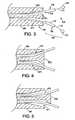
- Figure 3shows a structure 570 which is disposed at the distal end 170 of the catheter 140. The structure 570 causes the wires 110 and 120 to split into their respective slanted lumens, 572 and 571.
- the wires 110 and 120Prior to emerging from the distal end 170, the wires 110 and 120 follow the slanted luminal path 572 and 571 as defined by structure 570.
- divergent lumens at the distal end 170 of the catheter 140may be used to split the wires 110 and 120 into their divergent configuration 500.
- the divergent configuration 500as defined by the extension length of distal region 125 beyond distal end 170 of catheter 140, S, and the distance of separation between wires, L, may be manipulated and controlled by an actuator.
- the actuatormay be structure 570, as shown in Figure 3 .
- the width of the structure 570may be variably controlled at the proximal end 171 causing the slanted luminal paths 571 and 572 to increase or decrease, thereby altering the divergent configuration 500.
- Other actuators known to those of ordinary skill in the artare contemplated.
- the actuatormay also be the adjustable sliding stop 176, described in Figure 1 .
- Figure 4shows the electrosurgical cutting device 100 having wires 110 and 120 extended in one possible divergent cutting configuration 500.
- Figure 5illustrates electrosurgical cutting device 100 in another possible cutting configuration 500 having a smaller cutting position than that shown in Figure 4 . Less movement of the sliding member 193 may be required to generate the cutting position of Figure 5 than that of Figure 4 .
- Various other cutting positionsare possible.
- Figure 6is an example of the configuration during advancement of the electrosurgical cutting device 100 shown in Figure 1 to a target incision site.
- the wires 110 and 120are shown disposed within the lumen 160 of the catheter 140.
- the wires 110 and 120are substantially parallel to each other along the longitudinal length of the lumen 160 of the catheter 140.
- Figure 8is another possible configuration during advancement of the device 100.
- a single wire 109extends along the length of the catheter 140 within the lumen 160. At the distal region 125, the wire 109 splits into wires 110 and 120.
- Wires 110 and 120may be configured within the catheter 140 such that they cut along a x-y plane or a x-z plane, relative to the handle assembly 130. If wires 110 and 120 cut tissue along the x-y plane, wire 110 may be positioned above wire 120 within catheter 140. If wires 110 and 120 cut tissue along the x-z plane, wire 110 and wire 120 may be positioned side-by-side within the lumen 160 of catheter 140. Determining which configuration to utilize is dependent upon a number of factors, including the shape and size of tissue to be incised.
- Catheter 140is a flexible tubular member.
- the catheter 140is formed from any semi-rigid polymer.
- the catheter 140can be formed from polyurethane, polyethylene, tetrafluoroethylene, polytetrafluoroethylene, perfluoalkoxl, fluorinated ethylene propylene, or the like.
- the catheter 140may have a length of about 220 centimeters in order to sufficiently extend through the working channel of a conventional endoscope.
- Catheter 140may also have an outer diameter from about 6 to 7 French in order to fit within the working channel.
- the catheter 140may also have a hydrophilic coating 199 overlying its outer surface.
- hydrophilic coating 199when applied to the outer surface of the catheter 140, imparts suppleness and kink resistance to the catheter 140. Hydrophilic coating 199 also provides a highly lubricated surface to facilitate movement through the working channel of the endoscope.
- FIG. 7-14illustrate a method for performing an Endoscopic Mucosal Resection (EMR) procedure 400.
- the electrosurgical cutting device 100may be advanced through a working channel 201 of an endoscope 200 ( Figure 7 ).
- the device 100may be maneuvered into a patient down through the esophagus and duodenum, towards the target tissue site 300 within the gastrointestinal lumen 1 ( Figures 9 , 12 ).
- the distal regions 125 of the wires 110 and 120are maintained in a retracted position within the lumen 160 of the catheter 140, as shown in Figure 8 .
- the wires 110 and 120are maintained in a substantially compressed configuration.
- Figure 7is a partial cross-sectional view of the electrosurgical cutting device 100 in close proximity to the target tissue site 300.
- a physicianmay examine whether incision markings are needed to define the boundaries of the target tissue site 300. If the margins 303 of the target tissue site 300 are not readily discernible, a typical needle knife tip (not shown) may be loaded into an accessory channel of the endoscope 200 to create markings around the margins 303 of the target tissue 300 to be cut. High frequency current is applied to the tip to create the markings. Such methods for creating markings are well known to those of ordinary skill in the art. Alternatively, markings may be omitted where target tissue site 300 can readily be distinguished from the tissue not intended to be cut, as is the case in Figure 7 .
- the protrusionis created by injecting physiological saline solution through the hypodermic needle 180, which may be disposed within the lumen 181 of the catheter 140.
- the hypodermic needle 180may be inserted through the side port 133, as shown in Figure 1 .
- the hypodermic needle 180may be disposed in the same lumen as the electrosurgical cutting device 100.
- Figure 7shows the hypodermic needle 180 extending beyond the distal end 170 of the catheter 140 until it contacts target tissue site 300.
- a sufficient amount of saline solutionis injected into the submucosa 301.
- the submucosa 301swells, thereby allowing an incision to be made into the target tissue 300 without inadvertently injuring the underlying submucosa tissue 301.
- the hypodermic needle 180is retracted within the lumen 181.
- the hypodermic needle 180may be a separate component that is inserted through a working channel of the endoscope 200.
- Figure 9is an elevated view of the electrosurgical cutting device 100 contacting the target tissue site 300.
- the distal end 170 of the catheter 140is advanced into the target tissue site 300 with the wires 110 and 120 remaining retracted within the lumen 160 of the catheter 140.
- the wires 110 and 120may be substantially parallel to each other within the lumen 160, as shown in Figure 9 .
- the sliding member 193may be advanced distally, as indicated by the arrow in Figure 10 , to deploy the wires 110 and 120 beyond the distal end 170 of the catheter 140 and into the tissue of target tissue site 300.
- the divergent configuration 500may be formed.
- the divergent configuration 500may open inside the target tissue site 300.
- the wires 110 and 120are extended until they make sufficient contact with target tissue site 300 such that uninsulated regions 112 and 113 are disposed distal to a substantial portion of the target tissue site 300 to be incised. Insulated distal tips 111 and 121 are also disposed within target tissue site 300.
- Adjustable sliding stop 176may be moved to a desired position along the proximal region of the catheter 140 to limit the distance S that the wires 110 and 120 may be extended beyond the distal end 170 of the catheter 140. Upon reaching its desired position, sliding stop 176 ( Figure 1 ) may be locked into place. Sliding member 193 may be moved distally in the direction of the arrow until it abuts against adjustable sliding stop 176. This ensures that the distal regions 125 ( Figure 1 ) of wires 110 and 120 are maintained in its divergent configuration 500 at a predetermined distance S during the incision process. Additionally, although not shown, another sliding stop could be placed proximal of the sliding member 193 to prevent retraction of the wires 110 and 120.
- Electrical currentmay be applied from electrosurgical generator 190 ( Figure 1 ) at any time during the procedure to create the incision.
- the physiciansets the current at a setting typically used in such a procedure.
- Currentflows into the electrical port 191 ( Figure 1 ) and thereafter travels through the wires 110 and 120.
- Uninsulated portions 112 and 113( Figures 1 and 11 ) begin to increase in temperature due to resistive heating of these portions of the wires 110 and 120.
- pulling the cutting device 100 in the direction of the arrowcauses tissue 399 to be incised from target tissue 300.
- the divergent configuration 500may be formed within the target tissue site 300 and the divergent configuration 500 may be oriented distally relative to the target tissue site 300.
- Manipulation of the electrosurgical device 100either by rotational movement or various other movements, performs the necessary incisions within target tissue 300, as shown in Figure 11 .
- the tissue 399may be dragged along the outside of the divergent configuration 500.
- Figure 11shows incised tissue 399 dragged along the outside of the configuration of the 500.
- the extension length of the distal region 125 beyond the distal end 170 of the catheter 140, S, the distance of separation between the wires 110 and 120 as measured from the outer edges of distal tips 111 and 121, L, and the angular separation ⁇ between the wires 110 and 120( Figure 1 ) will determine the amount of tissue 399 that is incised. In this example, a length of about three centimeters of tissue 399 from target tissue site 300 is incised.
- Figures 12 and 13show another possible method of using the electrosurgical cutting device 100 to incise tissue.
- the distal end 170 of the catheter 140may be advanced toward the target tissue site 300 with the wires 110 and 120 already extending distally past the distal end 170 of the catheter 140.
- the divergent configuration 500is oriented proximal relative to the target tissue site 300, as shown in Figure 12 .
- the physicianpushes the electrosurgical cutting device 100 towards target tissue site 300 in the direction indicated by the arrow (distally) of Figure 12 .
- uninsulated portions 112 and 113begin to incise the target tissue site 300.
- Pushing the electrosurgical device 100 forwardcauses the target tissue site 300 to be incised and thereafter enter the interior of the divergent configuration 500.
- Electrical currentmay be applied from electrosurgical generator 190 ( Figure 1 ) at any time during the procedure to create the incision.
- Pulling the wires 110 and 120 in the proximal direction as indicated by the arrow in Figure 13causes the incised tissue from the target tissue site 300 to enter the divergent configuration 500. Similar to the cutting configuration described in Figures 9-11 , the extension length of the distal region 125 beyond the distal end 170 of the catheter 140, S, the distance of separation between the wires 110 and 120 as measured from the outer edges of distal tips 111 and 121, L, and the angular separation, ⁇ , between the wires 110 and 120 ( Figure 1 ) may determine the amount of tissue 300 that is incised.
- the handle assembly 130may be pulled to withdraw the electrosurgical cutting device 100 through the endoscope 200.
- a retrieval devicesuch as a snare 316 or forceps (not shown), may subsequently be used to remove the incised target tissue 300 through a working channel 201 of the endoscope 200, as shown in Figure 14 .
- the wires 110 and 120 of the electrosurgical cutting device 100may also form a particular divergent configuration 500 during the procedure 400 that causes some of the incised tissue to enter the divergent configuration 500 and some of the incised tissue to drag along the outside of the divergent configuration 500.
- the electrosurgical cutting device 100may be used in a non-EMR procedure.
- hypodermic needle 180( Figure 1 ) may be removed from the lumen 160 of the catheter 140.
- the method for incising tissueis substantially similar to that described above with reference to Figures 9-14 .
Landscapes
- Health & Medical Sciences (AREA)
- Life Sciences & Earth Sciences (AREA)
- Surgery (AREA)
- Engineering & Computer Science (AREA)
- Plasma & Fusion (AREA)
- Medical Informatics (AREA)
- Otolaryngology (AREA)
- Physics & Mathematics (AREA)
- Cardiology (AREA)
- Biomedical Technology (AREA)
- Heart & Thoracic Surgery (AREA)
- Nuclear Medicine, Radiotherapy & Molecular Imaging (AREA)
- Molecular Biology (AREA)
- Animal Behavior & Ethology (AREA)
- General Health & Medical Sciences (AREA)
- Public Health (AREA)
- Veterinary Medicine (AREA)
- Surgical Instruments (AREA)
Description
- The invention generally relates to an electrosurgical cutting device for removal of portions of the mucuosa and/or submucosa tissue from the gastrointestinal tract of a human being.
- Diagnostic and therapeutic gastrointestinal endoscopy are commonly used to gain access to the digestive tract for the purpose of removing tissue. Common endoscopy procedures include incision and ablation through various known mechanisms.
- Techniques for obtaining tissues for biopsies include endoscopic mucosectomy, also known as endoscopic mucosal resection (EMR). Endoscopic mucosectomy involves the removal of a portion (i.e., resection) of the digestive wall including the mucosal membrane. This procedure typically removes a part or even all of the submucosa. Endoscopic mucosectomy is a curative endoscopic procedure which is intended for sessile benign tumors and intramucosal cancers. The procedure makes it possible to determine precisely the nature of any subsequent treatment that may be required.
- The incision devices currently utilized in endoscopic mucosectomy make tissue removal difficult. These problems are compounded by the thick gastrointestinal wall that the incisions are performed within. Considerable time and effort is therefore required by the physician to incise and remove the desired tissue. The inability to quickly incise tissue may increase patient trauma. Moreover, current incision devices cannot remove tissue in unfragmented portions. Assessment of fragmented tissue becomes increasingly difficult during sampling as compared to assessment of unfragmented tissue. Furthermore, fragmented resection of early cancers may lead to a higher rate of local tumor recurrence.
- In view of the drawbacks of current technology, there is an unmet need for incision devices that can more efficiently remove mucosal and/or submucosal tissue in unfragmented portions in a relatively short period of time without inducing significant patient trauma.
- A device according to the preamble of
claim 1 is known from WO1999US20045. - The invention is defined in
claim 1. - Accordingly, an electrosurgical cutting device is provided that resolves or improves upon one or more of the above-described drawbacks.
- In a first aspect, an electrosurgical cutting device is disclosed. The device includes a catheter and two or more electrically conductive wires extending through a lumen of the catheter. The wires are movable between a retracted position and an extended cutting position. The wires form a divergent configuration in the extended cutting position.
- In a second aspect, a method for performing an EMR procedure is provided. An electrosurgical cutting device comprising a catheter, a plurality of electrically conductive resection wires disposed within a lumen of the catheter, and a handle assembly operably connected to a proximal end of the catheter is provided. Each of the plurality of resection wires comprises a cutting portion. The electrosurgical cutting device is advanced towards a target region having tissue to be incised. Each of the plurality of resection wires extend beyond the distal end of the catheter so as to form a divergent cutting configuration. Each of the plurality of resection wires engages with the target region. Electrical current is applied to the cutting portion of each of the plurality of the resection wires. The handle assembly is manipulated to incise the tissue of the target site and separate the tissue from underlying tissue.
- In a third aspect, a method for electrosurgically incising tissue is disclosed. An endoscope is maneuvered towards a target tissue site. An electrosurgical cutting device, which comprises a catheter, multiple electrically conductive cutting wires, and a handle assembly, is advanced into a working channel of an endoscope. Upon reaching the target tissue site, the handle assembly is manipulated in order for the wires to transform from their compressed, retracted configuration to their divergent cutting configuration. Electrical current is applied to the wires to incise tissue from the target tissue site.
- Embodiments will now be described by way of example with reference to the accompanying drawings, in which:
Figure 1 is a side view of an electrosurgical cutting device with the distal region of the electrically conductive wires extended beyond the distal end of the catheter in a divergent cutting configuration;Figure 2 is a side view of a hypodermic needle being loaded into a side port of the electrosurgical cutting device;Figure 3 is a partial cross-sectional view of the distal end of the electrosurgical cutting device with an actuator structure capable of controlling the divergent configuration of the wires;Figure 4 is a partial cross-sectional view of an electrosurgical cutting device with the wires in a particular extended divergent cutting configuration;Figure 5 is a partial cross-sectional view of an electrosurgical cutting device with the wires in another particular extended divergent cutting configuration;Figure 6 is a partial cross-sectional view of an electrosurgical cutting device with the wires retracted within the catheter in a substantially parallel position;Figure 7 is a partial cross-sectional view of an EMR procedure in which a hypodermic needle is injecting physiological saline solution into a target tissue region;Figure 8 is a partial cross-sectional view of the cutting device showing a single wire extending within the lumen of the catheter and splitting into two wires at the distal end of the catheter;Figure 9 is an elevational view of an EMR procedure in which the distal end of the cutting device is positioned within the target tissue;Figure 10 is an elevational view of an EMR procedure in which the wires are extended within the target tissue site;Figure 11 is an elevational view of an EMR procedure in which the incision of the target tissue is made and the incised tissue is dragged along the sides of the divergent configuration;Figure 12 is an elevational view of an EMR procedure in which the wires form a divergent cutting configuration proximal relative to the target tissue site;Figure 13 is an elevational view of an EMR procedure in which incised tissue enters the pocket of the divergent configuration; andFigure 14 is a partial cross-sectional view of a snare retrieving the incised tissue.- The embodiments are described with reference to the drawings in which like elements are referred to by like numerals. The relationship and functioning of the various elements of the embodiments are better understood by the following detailed description. However, the embodiments as described below are by way of example only, and the invention is not limited to the embodiments illustrated in the drawings. It should also be understood that the drawings are not to scale and in certain instances details have been omitted, which are not necessary for an understanding of the embodiments, such as conventional details of fabrication and assembly.
- An exemplary electrosurgical cutting device is shown in
Figure 1. Figure 1 is a side view showing theelectrosurgical cutting device 100 in an extended cutting position. Theelectrosurgical cutting device 100 includes acatheter 140 having adistal portion 170 and aproximal portion 171, ahandle assembly 130 attached to theproximal portion 171 of thecatheter 140, electricallyconductive wires lumen 160 of thecatheter 140, and ahypodermic needle 180 movably disposed within thelumen 160 of thecatheter 140. Thecatheter 140 is configured for coupling to anelectrosurgical generator 190. Theelectrosurgical generator 190 is connected to anelectrical port 191. Theelectrosurgical generator 190 supplies the electrical energy to thewires conductive wires wires wires Figure 1 . Many types of flared shapes are possible. In the example shown inFigure 1 , thewires divergent configuration 500. The term "divergent" as described herein refers to thewires Figures 1 and3 show thewires divergent configuration 500, other variations of thedivergent configuration 500 are contemplated. For example,wires - The
divergent configuration 500 creates an excise area for receiving tissue within the configuration and/or along the edges of theconfiguration 500. Electrical current from theelectrosurgical generator 190 may be applied as thewires divergent configuration 500 beyond thedistal end 170 of thecatheter 140. The current will heat thewires wires - Still referring to
Figure 1 , handleassembly 130 includes a slidingmember 193, athumb ring 192, and astem 177. Thestem 177 is fixedly attached to thecatheter 140, and the slidingmember 193 is fixedly attached to the proximal end of thewires member 193 is slidably connected to astem 177, which is affixed to theproximal portion 171 of thecatheter 140. Slidingmember 193 includes a pair of opposed finger rings 135 which enable a user to grasp the same with the forefinger and index finger. By placing a thumb throughthumb ring 192, the slidingmember 193 may be pushed and advanced towards thedistal end 170 to deploy the electricallyconductive wires distal end 170 of thecatheter 140. Slidingmember 193 may also be pulled proximally againststops 175 to retract thedistal region 125 ofwires distal end 170 of thecatheter 140. - An adjustable sliding
stop 176 may be disposed over thedistal portion 171 of thestem 177. The adjustable slidingstop 176 may be incrementally moved along theproximal portion 171 ofcatheter 140 to enable controlled extension of thedistal region 125 ofwires distal end 170 of thecatheter 140. This facilitates controlled positioning of thedistal region 125 of thewires distal end 170 of thecatheter 140 by a variable distanceS. Sliding member 193 has an internally disposedelectrical port 191 for making an electrical connection to anelectrosurgical generator 190. Theelectrosurgical generator 190 provides a cutting current as is well known to one of ordinary skill in the art. AlthoughFigure 1 shows thehandle assembly 130 and the adjustable slidingstop 176 as the apparatus for activating extension and retraction of thedistal region 125 ofwires - Referring to
Figure 2 , ahypodermic needle 180 may be inserted into aside port 133 of theelectrosurgical cutting device 100. Thehypodermic needle 180 may used to inject physiological saline solution into the target tissue. Any type of saline solution known in the art may be used. The saline solution may cause the target tissue to swell and elevate from the underlying normal tissue. Elevation of the target tissue may facilitate removal of the target tissue, such as cancerous tissue or other types of abnormal tissue, during an endoscopic mucosal resection procedure. The ability to remove the target tissue without cutting into it enables a more accurate assessment of the tissue than would otherwise be possible if sampling a fragmented tissue sample. Furthermore, fragmented resection of early cancers may lead to a higher rate of local tumor recurrence. AlthoughFigure 1 shows both thehypodermic needle 180 and thewires lumen 160,electrosurgical cutting device 100 may contain multiple lumens adapted for separately receiving theneedle 180 and thewires - Still referring to
Figure 1 ,wires distal end 170 of thecatheter 140 in the predetermineddivergent configuration 500. The proximal portions of thewires lumen 160 of thecatheter 140. Thedistal regions 125 of thewires distal end 170 of thecatheter 140.Distal region 125 ofwire 110 includes an insulatedproximal portion 116, an insulateddistal tip 111, and anuninsulated region 112 therebetween. Similarly,distal region 125 ofwire 120 includes an insulatedproximal portion 117, an insulateddistal tip 121, and anuninsulated region 113 therebetween.Insulated tips distal tips distal tips proximal portions proximal portions uninsulated wire regions uninsulated regions - Although the
electrosurgical cutting device 100 has been described as having twowires Figure 8 shows that asingle wire 109 may extend within thelumen 160 of thecatheter 140 and thereafter split into twowires distal region 125 of thecatheter 140.Figure 8 shows thewires lumen 160. Similar to the example ofFigure 1 , thewires Figure 8 are extendable pass the distal end of thecatheter 140 in a flared shape. - The cutting positions of the
wires divergent configuration 500 may be further defined by the extension length ofdistal region 125 beyond thedistal end 170 ofcatheter 140, S, the distance of separation betweenwires distal tips wires divergent configuration 500 for incising tissue. - One skilled in the art can determine a suitable diameter of
wires wires Figures 6 and 8 show thatwires lumen 160 ofcatheter 140. This is due to thecompression wires lumen 160. However, upon thedistal region 125 ofwires distal end 170 of thecatheter 140, thewires divergent configuration 500.- The divergence of the
wires wires divergent configuration 500. Thewires wires wires distal regions 125 ofwires divergent configuration 500. - In a preferred embodiment, the
wires wires wires wires electrosurgical generator 190, the crystalline transformation to the austenitic phase makes it much more difficult to deform. If a sufficient force is then applied to thewires wires Wires - The
wires distal end 170 of thecatheter 140 into adivergent configuration 500 by other known methods which do not require any heat treatment. Alternatively, other techniques for biasing thewires distal end 170 of thecatheter 140 may have structures that guide thewires wires Figure 3 shows astructure 570 which is disposed at thedistal end 170 of thecatheter 140. Thestructure 570 causes thewires distal end 170, thewires luminal path structure 570. Alternatively, divergent lumens at thedistal end 170 of thecatheter 140 may be used to split thewires divergent configuration 500. - Various types of divergent configuration configurations are possible as illustrated in
Figures 4 and 5 . Thedivergent configuration 500 as defined by the extension length ofdistal region 125 beyonddistal end 170 ofcatheter 140, S, and the distance of separation between wires, L, may be manipulated and controlled by an actuator. The actuator may bestructure 570, as shown inFigure 3 . The width of thestructure 570 may be variably controlled at theproximal end 171 causing the slantedluminal paths divergent configuration 500. Other actuators known to those of ordinary skill in the art are contemplated. The actuator may also be the adjustable slidingstop 176, described inFigure 1 . - As described above,
Figure 4 shows theelectrosurgical cutting device 100 havingwires divergent cutting configuration 500.Figure 5 illustrateselectrosurgical cutting device 100 in anotherpossible cutting configuration 500 having a smaller cutting position than that shown inFigure 4 . Less movement of the slidingmember 193 may be required to generate the cutting position ofFigure 5 than that ofFigure 4 . Various other cutting positions are possible. Figure 6 is an example of the configuration during advancement of theelectrosurgical cutting device 100 shown inFigure 1 to a target incision site. Thewires lumen 160 of thecatheter 140. Thewires lumen 160 of thecatheter 140.Figure 8 is another possible configuration during advancement of thedevice 100. Asingle wire 109 extends along the length of thecatheter 140 within thelumen 160. At thedistal region 125, thewire 109 splits intowires Wires catheter 140 such that they cut along a x-y plane or a x-z plane, relative to thehandle assembly 130. Ifwires wire 110 may be positioned abovewire 120 withincatheter 140. Ifwires wire 110 andwire 120 may be positioned side-by-side within thelumen 160 ofcatheter 140. Determining which configuration to utilize is dependent upon a number of factors, including the shape and size of tissue to be incised.Catheter 140 is a flexible tubular member. Thecatheter 140 is formed from any semi-rigid polymer. For example, thecatheter 140 can be formed from polyurethane, polyethylene, tetrafluoroethylene, polytetrafluoroethylene, perfluoalkoxl, fluorinated ethylene propylene, or the like. In a typical application, thecatheter 140 may have a length of about 220 centimeters in order to sufficiently extend through the working channel of a conventional endoscope.Catheter 140 may also have an outer diameter from about 6 to 7 French in order to fit within the working channel. Thecatheter 140 may also have ahydrophilic coating 199 overlying its outer surface. Thehydrophilic coating 199, when applied to the outer surface of thecatheter 140, imparts suppleness and kink resistance to thecatheter 140.Hydrophilic coating 199 also provides a highly lubricated surface to facilitate movement through the working channel of the endoscope.- A method of using the
electrosurgical cutting device 100 will now be described with reference toFigures 7-14 . In particular, and by way of example,Figures 7-14 illustrate a method for performing an Endoscopic Mucosal Resection (EMR)procedure 400. Theelectrosurgical cutting device 100 may be advanced through a workingchannel 201 of an endoscope 200 (Figure 7 ). Thedevice 100 may be maneuvered into a patient down through the esophagus and duodenum, towards thetarget tissue site 300 within the gastrointestinal lumen 1 (Figures 9 ,12 ). During advancement of theelectrosurgical cutting device 100 to atarget tissue site 300, thedistal regions 125 of thewires lumen 160 of thecatheter 140, as shown inFigure 8 . Thewires Figure 7 is a partial cross-sectional view of theelectrosurgical cutting device 100 in close proximity to thetarget tissue site 300. After selectively positioning theelectrosurgical cutting device 100 in proximity to thetarget tissue site 300, a physician may examine whether incision markings are needed to define the boundaries of thetarget tissue site 300. If themargins 303 of thetarget tissue site 300 are not readily discernible, a typical needle knife tip (not shown) may be loaded into an accessory channel of theendoscope 200 to create markings around themargins 303 of thetarget tissue 300 to be cut. High frequency current is applied to the tip to create the markings. Such methods for creating markings are well known to those of ordinary skill in the art. Alternatively, markings may be omitted wheretarget tissue site 300 can readily be distinguished from the tissue not intended to be cut, as is the case inFigure 7 .- After selectively positioning the
electrosurgical cutting device 100 in close proximity to thetarget tissue site 300, formation of a protrusion of thetarget tissue site 300 is the next step. The protrusion is created by injecting physiological saline solution through thehypodermic needle 180, which may be disposed within the lumen 181 of thecatheter 140. Thehypodermic needle 180 may be inserted through theside port 133, as shown inFigure 1 . Although not shown inFigure 7 , thehypodermic needle 180 may be disposed in the same lumen as theelectrosurgical cutting device 100.Figure 7 shows thehypodermic needle 180 extending beyond thedistal end 170 of thecatheter 140 until it contacts targettissue site 300. A sufficient amount of saline solution, as is known in the art, is injected into thesubmucosa 301. Thesubmucosa 301 swells, thereby allowing an incision to be made into thetarget tissue 300 without inadvertently injuring theunderlying submucosa tissue 301. After injection of the physiological saline is completed, thehypodermic needle 180 is retracted within the lumen 181. Although the figures illustrate theelectrosurgical cutting device 100 as a unitary structure with thehypodermic needle 180, thehypodermic needle 180 may be a separate component that is inserted through a working channel of theendoscope 200. - After the
target tissue site 300 has been sufficiently elevated, the process of creating the incision may begin.Figure 9 is an elevated view of theelectrosurgical cutting device 100 contacting thetarget tissue site 300. In particular, thedistal end 170 of thecatheter 140 is advanced into thetarget tissue site 300 with thewires lumen 160 of thecatheter 140. Thewires lumen 160, as shown inFigure 9 . - After the
distal end 170 of thecatheter 140 is contained within thetarget tissue site 300, the slidingmember 193 may be advanced distally, as indicated by the arrow inFigure 10 , to deploy thewires distal end 170 of thecatheter 140 and into the tissue oftarget tissue site 300. As thewires target tissue 300, thedivergent configuration 500 may be formed. Thedivergent configuration 500 may open inside thetarget tissue site 300. Thewires target tissue site 300 such thatuninsulated regions target tissue site 300 to be incised. Insulateddistal tips target tissue site 300. Adjustable sliding stop 176 (Figure 1 ) may be moved to a desired position along the proximal region of thecatheter 140 to limit the distance S that thewires distal end 170 of thecatheter 140. Upon reaching its desired position, sliding stop 176 (Figure 1 ) may be locked into place. Slidingmember 193 may be moved distally in the direction of the arrow until it abuts against adjustable slidingstop 176. This ensures that the distal regions 125 (Figure 1 ) ofwires divergent configuration 500 at a predetermined distance S during the incision process. Additionally, although not shown, another sliding stop could be placed proximal of the slidingmember 193 to prevent retraction of thewires - Electrical current may be applied from electrosurgical generator 190 (
Figure 1 ) at any time during the procedure to create the incision. The physician sets the current at a setting typically used in such a procedure. Current flows into the electrical port 191 (Figure 1 ) and thereafter travels through thewires Uninsulated portions 112 and 113 (Figures 1 and11 ) begin to increase in temperature due to resistive heating of these portions of thewires - As shown in
Figure 11 , pulling thecutting device 100 in the direction of the arrow (proximally) causestissue 399 to be incised fromtarget tissue 300. Thedivergent configuration 500 may be formed within thetarget tissue site 300 and thedivergent configuration 500 may be oriented distally relative to thetarget tissue site 300. Manipulation of theelectrosurgical device 100, either by rotational movement or various other movements, performs the necessary incisions withintarget tissue 300, as shown inFigure 11 . After the incision is made, thetissue 399 may be dragged along the outside of thedivergent configuration 500.Figure 11 shows incisedtissue 399 dragged along the outside of the configuration of the 500. The extension length of thedistal region 125 beyond thedistal end 170 of thecatheter 140, S, the distance of separation between thewires distal tips wires 110 and 120 (Figure 1 ) will determine the amount oftissue 399 that is incised. In this example, a length of about three centimeters oftissue 399 fromtarget tissue site 300 is incised. - Alternatively,
Figures 12 and13 show another possible method of using theelectrosurgical cutting device 100 to incise tissue. Unlike the method described inFigures 9-11 , thedistal end 170 of thecatheter 140 may be advanced toward thetarget tissue site 300 with thewires distal end 170 of thecatheter 140. This forms thedivergent configuration 500 prior to thedevice 100 entering thetarget tissue site 300. In other words, thedivergent configuration 500 is oriented proximal relative to thetarget tissue site 300, as shown inFigure 12 . With thewires divergent configuration 500, the physician pushes theelectrosurgical cutting device 100 towardstarget tissue site 300 in the direction indicated by the arrow (distally) ofFigure 12 . As shown inFigure 13 ,uninsulated portions target tissue site 300. Pushing theelectrosurgical device 100 forward causes thetarget tissue site 300 to be incised and thereafter enter the interior of thedivergent configuration 500. Electrical current may be applied from electrosurgical generator 190 (Figure 1 ) at any time during the procedure to create the incision. - Pulling the
wires Figure 13 causes the incised tissue from thetarget tissue site 300 to enter thedivergent configuration 500. Similar to the cutting configuration described inFigures 9-11 , the extension length of thedistal region 125 beyond thedistal end 170 of thecatheter 140, S, the distance of separation between thewires distal tips wires 110 and 120 (Figure 1 ) may determine the amount oftissue 300 that is incised. - After the
target tissue 300 has been incised, thehandle assembly 130 may be pulled to withdraw theelectrosurgical cutting device 100 through theendoscope 200. A retrieval device, such as asnare 316 or forceps (not shown), may subsequently be used to remove the incisedtarget tissue 300 through a workingchannel 201 of theendoscope 200, as shown inFigure 14 . - Although not shown in the Figures, the
wires electrosurgical cutting device 100 may also form a particulardivergent configuration 500 during theprocedure 400 that causes some of the incised tissue to enter thedivergent configuration 500 and some of the incised tissue to drag along the outside of thedivergent configuration 500. - In an alternative embodiment, the
electrosurgical cutting device 100 may be used in a non-EMR procedure. In such a procedure, because physiological saline solution may not be required to lift the target tissue from the underlying normal tissue, hypodermic needle 180 (Figure 1 ) may be removed from thelumen 160 of thecatheter 140. With the exception of no saline required to be injected to elevate the target tissue from the underlying normal tissue, the method for incising tissue is substantially similar to that described above with reference toFigures 9-14 . - The above figures and disclosure are intended to be illustrative and not exhaustive. This description will suggest many variations and alternatives to one of ordinary skill in the art. All such variations and alternatives are intended to be encompassed within the scope of the attached claims. Those familiar with the art may recognize other equivalents to the specific embodiments described herein which equivalents are also intended to be encompassed by the attached claims.
Claims (12)
- An electrosurgical cutting device comprising:a catheter (140) having a proximal end (171), a distal end (170), and one or more lumens extending from the proximal end to the distal end of the catheter, the catheter being configured for coupling to an electrosurgical generator; anda plurality of electrically conductive cutting wires (110, 120) disposed within the one or more lumens movable between a retracted position and an extended cutting position, wherein in the extended cutting position a distal region of the wires extends outwardly from the distal end of the catheter to form a divergent cutting configuration (500);characterised in that:a structure (570) is disposed at the distal end of the catheter causing the wires to split into respective slanted lumens (572, 571);wherein the structure (570) is adapted to be variably controlled at the proximal end of the catheter causing the slanted luminal paths to increase or decrease thereby altering the divergent configuration (500).
- The electrosurgical cutting device of claim 1, further comprising a handle operably connected to the proximal end of the catheter, wherein the handle is configured to manipulate the electrically conductive cutting wires between the retracted position and the extended cutting position.
- The electrosurgical cutting device of claim 2, wherein the handle comprises a sliding member slidably disposed on a stem.
- The electrosurgical device of claim 2, wherein the handle is coupled to an electrosurgical generator for providing electrical current to the wires.
- The electrosurgical cutting device of any preceding claim, further comprising a hypodermic needle extendable from the proximal end to the distal end of the catheter.
- The electrosurgical cutting device of any preceding claim, wherein each of the plurality of the electrically conductive wires, when in the retracted position, is positioned within the distal end of the catheter and substantially parallel to each other.
- The electrosurgical device of any preceding claim, wherein each of the plurality of wires further comprises an uninsulated portion between a proximal portion and a distal tip, the proximal portion and the distal tip being insulated, the uninsulated portion being adapted for incising tissue.
- The electrosurgical device of claim 7, wherein the distal tip of each of the plurality of the wires is insulated with ceramic.
- The electrosurgical device of any preceding claim, wherein the proximal portion of the distal region of each of the plurality of wires is insulated with polytetrafluoroethylene.
- The electrosurgical device of any preceding claim, wherein each of the plurality of the wires is formed from a metallic alloy.
- The electrosurgical device of any preceding claim, wherein the catheter has a length of about 150 centimeters to about 220 centimeters and a diameter ranging from about 6 French to about 7 French.
- The electrosurgical device of any preceding claim, wherein the distal region of each of the plurality of wires is insulated at a proximal portion and at a distal tip.
Applications Claiming Priority (2)
| Application Number | Priority Date | Filing Date | Title |
|---|---|---|---|
| US78820706P | 2006-03-31 | 2006-03-31 | |
| PCT/US2007/007762WO2007126949A1 (en) | 2006-03-31 | 2007-03-28 | Electrosurgical cutting device |
Publications (2)
| Publication Number | Publication Date |
|---|---|
| EP2012695A1 EP2012695A1 (en) | 2009-01-14 |
| EP2012695B1true EP2012695B1 (en) | 2015-07-22 |
Family
ID=38434001
Family Applications (1)
| Application Number | Title | Priority Date | Filing Date |
|---|---|---|---|
| EP07754304.9AActiveEP2012695B1 (en) | 2006-03-31 | 2007-03-28 | Electrosurgical cutting device |
Country Status (6)
| Country | Link |
|---|---|
| US (1) | US20080015574A1 (en) |
| EP (1) | EP2012695B1 (en) |
| JP (1) | JP5297371B2 (en) |
| AU (1) | AU2007245051A1 (en) |
| CA (1) | CA2647691C (en) |
| WO (1) | WO2007126949A1 (en) |
Families Citing this family (7)
| Publication number | Priority date | Publication date | Assignee | Title |
|---|---|---|---|---|
| US20070255278A1 (en)* | 2006-04-28 | 2007-11-01 | Nobis Rudolph H | Apparatus and method for deploying a cutting element during an endoscopic mucosal resection |
| US7651491B2 (en)* | 2006-04-28 | 2010-01-26 | Ethicon Endo-Surgery, Inc. | Method for performing an endoscopic mucosal resection |
| US7867228B2 (en)* | 2006-04-28 | 2011-01-11 | Ethicon Endo-Surgery, Inc. | Apparatus and method for performing an endoscopic mucosal resection |
| US20070270643A1 (en)* | 2006-05-19 | 2007-11-22 | Ifung Lu | Lumen stabilizer for endoscopic mucosal resection |
| US10869670B2 (en)* | 2018-03-26 | 2020-12-22 | Olympus Corporation | Procedure for endoscopic full-thickness resection |
| CN112716567A (en)* | 2020-12-28 | 2021-04-30 | 上海市同济医院 | Novel mucosa is peeled off under scope device |
| IT202100024116A1 (en)* | 2021-09-20 | 2023-03-20 | Enki Srl | DEVICE AND METHOD OF RELEASING A WIRE FROM A PIPE |
Citations (1)
| Publication number | Priority date | Publication date | Assignee | Title |
|---|---|---|---|---|
| WO2000013602A2 (en)* | 1998-09-04 | 2000-03-16 | Rita Medical Systems, Inc. | Electrosurgical device for cell necrosis induction |
Family Cites Families (72)
| Publication number | Priority date | Publication date | Assignee | Title |
|---|---|---|---|---|
| DE2132808C3 (en)* | 1971-07-01 | 1981-10-29 | Deyhle, Peter, Dr.med., 8520 Erlangen | Device for the diathermic removal of growths |
| JPS5727445Y2 (en)* | 1973-06-20 | 1982-06-15 | ||
| DE2513868C2 (en)* | 1974-04-01 | 1982-11-04 | Olympus Optical Co., Ltd., Tokyo | Bipolar electrodiathermy forceps |
| JPS5552748A (en)* | 1978-10-12 | 1980-04-17 | Olympus Optical Co | Highhfrequency incising tool |
| US4418692A (en)* | 1978-11-17 | 1983-12-06 | Guay Jean Louis | Device for treating living tissue with an electric current |
| DE3247793C2 (en)* | 1981-12-31 | 1986-01-09 | Harald 7200 Tuttlingen Maslanka | High frequency surgical loop electrode |
| US4493320A (en)* | 1982-04-02 | 1985-01-15 | Treat Michael R | Bipolar electrocautery surgical snare |
| US5370675A (en)* | 1992-08-12 | 1994-12-06 | Vidamed, Inc. | Medical probe device and method |
| US5078717A (en)* | 1989-04-13 | 1992-01-07 | Everest Medical Corporation | Ablation catheter with selectively deployable electrodes |
| EP0448857A1 (en)* | 1990-03-27 | 1991-10-02 | Jong-Khing Huang | An apparatus of a spinning type of resectoscope for prostatectomy |
| US5078716A (en)* | 1990-05-11 | 1992-01-07 | Doll Larry F | Electrosurgical apparatus for resecting abnormal protruding growth |
| US5026371A (en)* | 1990-10-01 | 1991-06-25 | Everest Medical Corporation | Handle for polypectome snare with bipolar electrodes |
| US5327889A (en)* | 1992-12-01 | 1994-07-12 | Cardiac Pathways Corporation | Mapping and ablation catheter with individually deployable arms and method |
| US5562703A (en)* | 1994-06-14 | 1996-10-08 | Desai; Ashvin H. | Endoscopic surgical instrument |
| US5237996A (en)* | 1992-02-11 | 1993-08-24 | Waldman Lewis K | Endocardial electrical mapping catheter |
| US5486161A (en)* | 1993-02-02 | 1996-01-23 | Zomed International | Medical probe device and method |
| US5470308A (en)* | 1992-08-12 | 1995-11-28 | Vidamed, Inc. | Medical probe with biopsy stylet |
| US5445638B1 (en)* | 1993-03-08 | 1998-05-05 | Everest Medical Corp | Bipolar coagulation and cutting forceps |
| US5403311A (en)* | 1993-03-29 | 1995-04-04 | Boston Scientific Corporation | Electro-coagulation and ablation and other electrotherapeutic treatments of body tissue |
| US5395368A (en)* | 1993-05-20 | 1995-03-07 | Ellman; Alan G. | Multiple-wire electrosurgical electrodes |
| US5551426A (en)* | 1993-07-14 | 1996-09-03 | Hummel; John D. | Intracardiac ablation and mapping catheter |
| US5376094A (en)* | 1993-08-19 | 1994-12-27 | Boston Scientific Corporation | Improved actuating handle with pulley system for providing mechanical advantage to a surgical working element |
| US5437665A (en)* | 1993-10-12 | 1995-08-01 | Munro; Malcolm G. | Electrosurgical loop electrode instrument for laparoscopic surgery |
| US5536267A (en)* | 1993-11-08 | 1996-07-16 | Zomed International | Multiple electrode ablation apparatus |
| SE9402775D0 (en)* | 1994-08-19 | 1994-08-19 | Siemens Elema Ab | Electrode device for intracardiac stimulation of the heart tissue and / or sensing of the heart signals of a patient |
| JPH0856951A (en)* | 1994-08-25 | 1996-03-05 | Olympus Optical Co Ltd | Clamping forceps for endoscope |
| US5836947A (en)* | 1994-10-07 | 1998-11-17 | Ep Technologies, Inc. | Flexible structures having movable splines for supporting electrode elements |
| US6575967B1 (en)* | 1995-03-24 | 2003-06-10 | The Board Of Regents Of The University Of Nebraska | Method and systems for volumetric tissue ablation |
| US5868740A (en)* | 1995-03-24 | 1999-02-09 | Board Of Regents-Univ Of Nebraska | Method for volumetric tissue ablation |
| US5810804A (en)* | 1995-08-15 | 1998-09-22 | Rita Medical Systems | Multiple antenna ablation apparatus and method with cooling element |
| JP3716477B2 (en)* | 1995-12-25 | 2005-11-16 | 日本ゼオン株式会社 | Dipole electrosurgical instrument |
| US6016452A (en)* | 1996-03-19 | 2000-01-18 | Kasevich; Raymond S. | Dynamic heating method and radio frequency thermal treatment |
| US6488673B1 (en)* | 1997-04-07 | 2002-12-03 | Broncus Technologies, Inc. | Method of increasing gas exchange of a lung |
| US7425212B1 (en)* | 1998-06-10 | 2008-09-16 | Asthmatx, Inc. | Devices for modification of airways by transfer of energy |
| JP3730757B2 (en)* | 1997-07-30 | 2006-01-05 | オリンパス株式会社 | Endoscopic treatment tool |
| US6063082A (en)* | 1997-11-04 | 2000-05-16 | Scimed Life Systems, Inc. | Percutaneous myocardial revascularization basket delivery system and radiofrequency therapeutic device |
| US6645201B1 (en)* | 1998-02-19 | 2003-11-11 | Curon Medical, Inc. | Systems and methods for treating dysfunctions in the intestines and rectum |
| JPH11318926A (en)* | 1998-05-08 | 1999-11-24 | Olympus Optical Co Ltd | Treatment instrument for high frequency therapy |
| JPH11332880A (en)* | 1998-05-22 | 1999-12-07 | Olympus Optical Co Ltd | Puncture treatment apparatus |
| US5944728A (en)* | 1998-04-23 | 1999-08-31 | Boston Scientific Corporation | Surgical retrieval basket with the ability to capture and release material |
| US6296639B1 (en)* | 1999-02-12 | 2001-10-02 | Novacept | Apparatuses and methods for interstitial tissue removal |
| JP3426510B2 (en)* | 1998-07-27 | 2003-07-14 | ペンタックス株式会社 | High frequency snare for endoscope |
| JP3684085B2 (en)* | 1998-09-02 | 2005-08-17 | ペンタックス株式会社 | Endoscopic wire loop treatment tool |
| US6015415A (en)* | 1999-03-09 | 2000-01-18 | General Science And Technology | Polypectomy snare instrument |
| DE19919072C2 (en)* | 1999-04-27 | 2001-12-13 | Wolf Gmbh Richard | Bipolar forceps |
| US6773432B1 (en)* | 1999-10-14 | 2004-08-10 | Applied Medical Resources Corporation | Electrosurgical snare |
| US6287304B1 (en)* | 1999-10-15 | 2001-09-11 | Neothermia Corporation | Interstitial cauterization of tissue volumes with electrosurgically deployed electrodes |
| US6770070B1 (en)* | 2000-03-17 | 2004-08-03 | Rita Medical Systems, Inc. | Lung treatment apparatus and method |
| JP4723156B2 (en)* | 2000-03-31 | 2011-07-13 | アンジオ ダイナミクス インコーポレイテッド | Tissue biopsy and treatment equipment |
| US20020022864A1 (en)* | 2000-06-07 | 2002-02-21 | Mahvi David M. | Multipolar electrode system for radiofrequency ablation |
| US6712771B2 (en)* | 2000-06-16 | 2004-03-30 | Accumed Systems, Inc. | Temperature sensing catheter |
| US6638277B2 (en)* | 2000-07-06 | 2003-10-28 | Scimed Life Systems, Inc. | Tumor ablation needle with independently activated and independently traversing tines |
| JP3989170B2 (en)* | 2000-10-05 | 2007-10-10 | オリンパス株式会社 | High frequency treatment tool |
| US6638275B1 (en)* | 2000-10-05 | 2003-10-28 | Medironic, Inc. | Bipolar ablation apparatus and method |
| EP1363700A4 (en)* | 2001-01-11 | 2005-11-09 | Rita Medical Systems Inc | Bone-treatment instrument and method |
| US7087040B2 (en)* | 2001-02-28 | 2006-08-08 | Rex Medical, L.P. | Apparatus for delivering ablation fluid to treat lesions |
| JP2002301088A (en)* | 2001-04-05 | 2002-10-15 | Olympus Optical Co Ltd | Endoscopic treatment device |
| US6743228B2 (en)* | 2001-09-12 | 2004-06-01 | Manoa Medical, Inc. | Devices and methods for tissue severing and removal |
| JP4450622B2 (en)* | 2001-09-28 | 2010-04-14 | アンジオ ダイナミクス インコーポレイテッド | Impedance-controlled tissue peeling device and method |
| US6736812B2 (en)* | 2002-06-19 | 2004-05-18 | Scimed Life Systems, Inc. | Dual short throw advancer/retractor |
| US7377925B2 (en)* | 2003-09-16 | 2008-05-27 | Minimally Invasive Devices, Llc | Fragmentation and extraction basket |
| US7291147B1 (en)* | 2004-02-02 | 2007-11-06 | Ellman Alan A | Forehead and brow lift bipolar forceps |
| US7344534B2 (en)* | 2004-09-03 | 2008-03-18 | Ethicon Endo-Surgery, Inc. | Ablation device |
| JP2006068406A (en)* | 2004-09-06 | 2006-03-16 | Pentax Corp | High-frequency snare for endoscope and manufacturing method thereof |
| US20060064113A1 (en)* | 2004-09-17 | 2006-03-23 | Nakao Naomi L | Endoscopic mucosal resection method and associated instrument |
| US7429261B2 (en)* | 2004-11-24 | 2008-09-30 | Ablation Frontiers, Inc. | Atrial ablation catheter and method of use |
| US7789881B2 (en)* | 2005-08-25 | 2010-09-07 | Boston Scientific Scimed, Inc. | Endoscopic resection method |
| JP4137931B2 (en)* | 2005-10-28 | 2008-08-20 | オリンパスメディカルシステムズ株式会社 | Endoscopic treatment tool |
| US7651491B2 (en)* | 2006-04-28 | 2010-01-26 | Ethicon Endo-Surgery, Inc. | Method for performing an endoscopic mucosal resection |
| JP4546424B2 (en)* | 2006-07-04 | 2010-09-15 | オリンパスメディカルシステムズ株式会社 | Endoscopic treatment tool |
| EP2068739A4 (en)* | 2006-09-14 | 2013-01-23 | Lazure Technologies Llc | Device and method for destruction of cancer cells |
| US7691104B2 (en)* | 2007-07-25 | 2010-04-06 | Olympus Medical Systems Corporation | Endoscopic treatment tool |
- 2007
- 2007-03-28EPEP07754304.9Apatent/EP2012695B1/enactiveActive
- 2007-03-28USUS11/729,402patent/US20080015574A1/ennot_activeAbandoned
- 2007-03-28WOPCT/US2007/007762patent/WO2007126949A1/enactiveApplication Filing
- 2007-03-28AUAU2007245051Apatent/AU2007245051A1/ennot_activeAbandoned
- 2007-03-28CACA2647691Apatent/CA2647691C/enactiveActive
- 2007-03-28JPJP2009502994Apatent/JP5297371B2/ennot_activeExpired - Fee Related
Patent Citations (1)
| Publication number | Priority date | Publication date | Assignee | Title |
|---|---|---|---|---|
| WO2000013602A2 (en)* | 1998-09-04 | 2000-03-16 | Rita Medical Systems, Inc. | Electrosurgical device for cell necrosis induction |
Also Published As
| Publication number | Publication date |
|---|---|
| CA2647691A1 (en) | 2007-11-08 |
| CA2647691C (en) | 2014-07-08 |
| AU2007245051A1 (en) | 2007-11-08 |
| EP2012695A1 (en) | 2009-01-14 |
| JP5297371B2 (en) | 2013-09-25 |
| WO2007126949A1 (en) | 2007-11-08 |
| JP2009532094A (en) | 2009-09-10 |
| US20080015574A1 (en) | 2008-01-17 |
Similar Documents
| Publication | Publication Date | Title |
|---|---|---|
| US8251991B2 (en) | Anchored RF ablation device for the destruction of tissue masses | |
| EP2658456B1 (en) | Snare with retractable engaging members | |
| EP2263550B1 (en) | Telescoping biopsy device | |
| EP2012695B1 (en) | Electrosurgical cutting device | |
| EP3785654B1 (en) | Multifunctional high-frequency electric knife | |
| EP2797518B1 (en) | Adjustable resection device | |
| US9901363B2 (en) | Resection device and related methods of use | |
| JP7445596B2 (en) | Blood vessel sampling device and method | |
| US10363087B2 (en) | Tissue resection device | |
| EP1887958B1 (en) | Cautery catheter | |
| JP6559889B2 (en) | Retractable tissue cutting device | |
| US10548626B2 (en) | Endoscopic tissue manipulation tool | |
| US20240074774A1 (en) | Endoscopic open wire snare system | |
| US20140276814A1 (en) | Tissue resection device and related methods of use |
Legal Events
| Date | Code | Title | Description |
|---|---|---|---|
| PUAI | Public reference made under article 153(3) epc to a published international application that has entered the european phase | Free format text:ORIGINAL CODE: 0009012 | |
| 17P | Request for examination filed | Effective date:20081006 | |
| AK | Designated contracting states | Kind code of ref document:A1 Designated state(s):AT BE BG CH CY CZ DE DK EE ES FI FR GB GR HU IE IS IT LI LT LU LV MC MT NL PL PT RO SE SI SK TR | |
| AX | Request for extension of the european patent | Extension state:AL BA HR MK RS | |
| 17Q | First examination report despatched | Effective date:20090219 | |
| RAP1 | Party data changed (applicant data changed or rights of an application transferred) | Owner name:COOK MEDICAL TECHNOLOGIES LLC | |
| RAP1 | Party data changed (applicant data changed or rights of an application transferred) | Owner name:COOK MEDICAL TECHNOLOGIES LLC | |
| DAX | Request for extension of the european patent (deleted) | ||
| GRAP | Despatch of communication of intention to grant a patent | Free format text:ORIGINAL CODE: EPIDOSNIGR1 | |
| INTG | Intention to grant announced | Effective date:20150331 | |
| GRAS | Grant fee paid | Free format text:ORIGINAL CODE: EPIDOSNIGR3 | |
| GRAA | (expected) grant | Free format text:ORIGINAL CODE: 0009210 | |
| AK | Designated contracting states | Kind code of ref document:B1 Designated state(s):AT BE BG CH CY CZ DE DK EE ES FI FR GB GR HU IE IS IT LI LT LU LV MC MT NL PL PT RO SE SI SK TR | |
| REG | Reference to a national code | Ref country code:GB Ref legal event code:FG4D | |
| REG | Reference to a national code | Ref country code:CH Ref legal event code:EP | |
| REG | Reference to a national code | Ref country code:IE Ref legal event code:FG4D | |
| REG | Reference to a national code | Ref country code:AT Ref legal event code:REF Ref document number:737422 Country of ref document:AT Kind code of ref document:T Effective date:20150815 | |
| REG | Reference to a national code | Ref country code:DE Ref legal event code:R096 Ref document number:602007042258 Country of ref document:DE | |
| REG | Reference to a national code | Ref country code:AT Ref legal event code:MK05 Ref document number:737422 Country of ref document:AT Kind code of ref document:T Effective date:20150722 | |
| REG | Reference to a national code | Ref country code:LT Ref legal event code:MG4D | |
| REG | Reference to a national code | Ref country code:NL Ref legal event code:MP Effective date:20150722 | |
| PG25 | Lapsed in a contracting state [announced via postgrant information from national office to epo] | Ref country code:FI Free format text:LAPSE BECAUSE OF FAILURE TO SUBMIT A TRANSLATION OF THE DESCRIPTION OR TO PAY THE FEE WITHIN THE PRESCRIBED TIME-LIMIT Effective date:20150722 Ref country code:GR Free format text:LAPSE BECAUSE OF FAILURE TO SUBMIT A TRANSLATION OF THE DESCRIPTION OR TO PAY THE FEE WITHIN THE PRESCRIBED TIME-LIMIT Effective date:20151023 Ref country code:LT Free format text:LAPSE BECAUSE OF FAILURE TO SUBMIT A TRANSLATION OF THE DESCRIPTION OR TO PAY THE FEE WITHIN THE PRESCRIBED TIME-LIMIT Effective date:20150722 Ref country code:LV Free format text:LAPSE BECAUSE OF FAILURE TO SUBMIT A TRANSLATION OF THE DESCRIPTION OR TO PAY THE FEE WITHIN THE PRESCRIBED TIME-LIMIT Effective date:20150722 | |
| PG25 | Lapsed in a contracting state [announced via postgrant information from national office to epo] | Ref country code:ES Free format text:LAPSE BECAUSE OF FAILURE TO SUBMIT A TRANSLATION OF THE DESCRIPTION OR TO PAY THE FEE WITHIN THE PRESCRIBED TIME-LIMIT Effective date:20150722 Ref country code:SE Free format text:LAPSE BECAUSE OF FAILURE TO SUBMIT A TRANSLATION OF THE DESCRIPTION OR TO PAY THE FEE WITHIN THE PRESCRIBED TIME-LIMIT Effective date:20150722 Ref country code:IS Free format text:LAPSE BECAUSE OF FAILURE TO SUBMIT A TRANSLATION OF THE DESCRIPTION OR TO PAY THE FEE WITHIN THE PRESCRIBED TIME-LIMIT Effective date:20151122 Ref country code:PL Free format text:LAPSE BECAUSE OF FAILURE TO SUBMIT A TRANSLATION OF THE DESCRIPTION OR TO PAY THE FEE WITHIN THE PRESCRIBED TIME-LIMIT Effective date:20150722 Ref country code:PT Free format text:LAPSE BECAUSE OF FAILURE TO SUBMIT A TRANSLATION OF THE DESCRIPTION OR TO PAY THE FEE WITHIN THE PRESCRIBED TIME-LIMIT Effective date:20151123 Ref country code:AT Free format text:LAPSE BECAUSE OF FAILURE TO SUBMIT A TRANSLATION OF THE DESCRIPTION OR TO PAY THE FEE WITHIN THE PRESCRIBED TIME-LIMIT Effective date:20150722 | |
| REG | Reference to a national code | Ref country code:DE Ref legal event code:R097 Ref document number:602007042258 Country of ref document:DE | |
| PG25 | Lapsed in a contracting state [announced via postgrant information from national office to epo] | Ref country code:EE Free format text:LAPSE BECAUSE OF FAILURE TO SUBMIT A TRANSLATION OF THE DESCRIPTION OR TO PAY THE FEE WITHIN THE PRESCRIBED TIME-LIMIT Effective date:20150722 Ref country code:IT Free format text:LAPSE BECAUSE OF FAILURE TO SUBMIT A TRANSLATION OF THE DESCRIPTION OR TO PAY THE FEE WITHIN THE PRESCRIBED TIME-LIMIT Effective date:20150722 Ref country code:CZ Free format text:LAPSE BECAUSE OF FAILURE TO SUBMIT A TRANSLATION OF THE DESCRIPTION OR TO PAY THE FEE WITHIN THE PRESCRIBED TIME-LIMIT Effective date:20150722 Ref country code:SK Free format text:LAPSE BECAUSE OF FAILURE TO SUBMIT A TRANSLATION OF THE DESCRIPTION OR TO PAY THE FEE WITHIN THE PRESCRIBED TIME-LIMIT Effective date:20150722 Ref country code:DK Free format text:LAPSE BECAUSE OF FAILURE TO SUBMIT A TRANSLATION OF THE DESCRIPTION OR TO PAY THE FEE WITHIN THE PRESCRIBED TIME-LIMIT Effective date:20150722 | |
| PLBE | No opposition filed within time limit | Free format text:ORIGINAL CODE: 0009261 | |
| STAA | Information on the status of an ep patent application or granted ep patent | Free format text:STATUS: NO OPPOSITION FILED WITHIN TIME LIMIT | |
| PG25 | Lapsed in a contracting state [announced via postgrant information from national office to epo] | Ref country code:RO Free format text:LAPSE BECAUSE OF FAILURE TO SUBMIT A TRANSLATION OF THE DESCRIPTION OR TO PAY THE FEE WITHIN THE PRESCRIBED TIME-LIMIT Effective date:20150722 | |
| 26N | No opposition filed | Effective date:20160425 | |
| PG25 | Lapsed in a contracting state [announced via postgrant information from national office to epo] | Ref country code:BE Free format text:LAPSE BECAUSE OF NON-PAYMENT OF DUE FEES Effective date:20160331 Ref country code:SI Free format text:LAPSE BECAUSE OF FAILURE TO SUBMIT A TRANSLATION OF THE DESCRIPTION OR TO PAY THE FEE WITHIN THE PRESCRIBED TIME-LIMIT Effective date:20150722 | |
| PG25 | Lapsed in a contracting state [announced via postgrant information from national office to epo] | Ref country code:LU Free format text:LAPSE BECAUSE OF FAILURE TO SUBMIT A TRANSLATION OF THE DESCRIPTION OR TO PAY THE FEE WITHIN THE PRESCRIBED TIME-LIMIT Effective date:20160328 Ref country code:MC Free format text:LAPSE BECAUSE OF FAILURE TO SUBMIT A TRANSLATION OF THE DESCRIPTION OR TO PAY THE FEE WITHIN THE PRESCRIBED TIME-LIMIT Effective date:20150722 | |
| REG | Reference to a national code | Ref country code:CH Ref legal event code:PL | |
| PG25 | Lapsed in a contracting state [announced via postgrant information from national office to epo] | Ref country code:BE Free format text:LAPSE BECAUSE OF FAILURE TO SUBMIT A TRANSLATION OF THE DESCRIPTION OR TO PAY THE FEE WITHIN THE PRESCRIBED TIME-LIMIT Effective date:20150722 | |
| REG | Reference to a national code | Ref country code:FR Ref legal event code:ST Effective date:20161130 | |
| PG25 | Lapsed in a contracting state [announced via postgrant information from national office to epo] | Ref country code:LI Free format text:LAPSE BECAUSE OF NON-PAYMENT OF DUE FEES Effective date:20160331 Ref country code:FR Free format text:LAPSE BECAUSE OF NON-PAYMENT OF DUE FEES Effective date:20160331 Ref country code:CH Free format text:LAPSE BECAUSE OF NON-PAYMENT OF DUE FEES Effective date:20160331 | |
| PG25 | Lapsed in a contracting state [announced via postgrant information from national office to epo] | Ref country code:NL Free format text:LAPSE BECAUSE OF FAILURE TO SUBMIT A TRANSLATION OF THE DESCRIPTION OR TO PAY THE FEE WITHIN THE PRESCRIBED TIME-LIMIT Effective date:20150722 | |
| PG25 | Lapsed in a contracting state [announced via postgrant information from national office to epo] | Ref country code:MT Free format text:LAPSE BECAUSE OF FAILURE TO SUBMIT A TRANSLATION OF THE DESCRIPTION OR TO PAY THE FEE WITHIN THE PRESCRIBED TIME-LIMIT Effective date:20150722 | |
| PG25 | Lapsed in a contracting state [announced via postgrant information from national office to epo] | Ref country code:HU Free format text:LAPSE BECAUSE OF FAILURE TO SUBMIT A TRANSLATION OF THE DESCRIPTION OR TO PAY THE FEE WITHIN THE PRESCRIBED TIME-LIMIT; INVALID AB INITIO Effective date:20070328 Ref country code:CY Free format text:LAPSE BECAUSE OF FAILURE TO SUBMIT A TRANSLATION OF THE DESCRIPTION OR TO PAY THE FEE WITHIN THE PRESCRIBED TIME-LIMIT Effective date:20150722 | |
| PG25 | Lapsed in a contracting state [announced via postgrant information from national office to epo] | Ref country code:MT Free format text:LAPSE BECAUSE OF FAILURE TO SUBMIT A TRANSLATION OF THE DESCRIPTION OR TO PAY THE FEE WITHIN THE PRESCRIBED TIME-LIMIT Effective date:20160331 Ref country code:TR Free format text:LAPSE BECAUSE OF FAILURE TO SUBMIT A TRANSLATION OF THE DESCRIPTION OR TO PAY THE FEE WITHIN THE PRESCRIBED TIME-LIMIT Effective date:20150722 | |
| PG25 | Lapsed in a contracting state [announced via postgrant information from national office to epo] | Ref country code:BG Free format text:LAPSE BECAUSE OF FAILURE TO SUBMIT A TRANSLATION OF THE DESCRIPTION OR TO PAY THE FEE WITHIN THE PRESCRIBED TIME-LIMIT Effective date:20150722 | |
| P01 | Opt-out of the competence of the unified patent court (upc) registered | Effective date:20230602 | |
| PGFP | Annual fee paid to national office [announced via postgrant information from national office to epo] | Ref country code:IE Payment date:20240226 Year of fee payment:18 | |
| PGFP | Annual fee paid to national office [announced via postgrant information from national office to epo] | Ref country code:DE Payment date:20240209 Year of fee payment:18 Ref country code:GB Payment date:20240208 Year of fee payment:18 |