EP2012653B1 - Hybrid spectral domain optical coherence tomography line scanning laser ophthalmoscope - Google Patents
Hybrid spectral domain optical coherence tomography line scanning laser ophthalmoscopeDownload PDFInfo
- Publication number
- EP2012653B1 EP2012653B1EP07756178AEP07756178AEP2012653B1EP 2012653 B1EP2012653 B1EP 2012653B1EP 07756178 AEP07756178 AEP 07756178AEP 07756178 AEP07756178 AEP 07756178AEP 2012653 B1EP2012653 B1EP 2012653B1
- Authority
- EP
- European Patent Office
- Prior art keywords
- light
- lslo
- oct
- mode
- eye
- Prior art date
- Legal status (The legal status is an assumption and is not a legal conclusion. Google has not performed a legal analysis and makes no representation as to the accuracy of the status listed.)
- Not-in-force
Links
- 238000012014optical coherence tomographyMethods0.000titleclaimsdescription147
- 230000003595spectral effectEffects0.000titleclaimsdescription5
- 230000003287optical effectEffects0.000claimsdescription97
- 238000003384imaging methodMethods0.000claimsdescription62
- 210000001525retinaAnatomy0.000claimsdescription24
- 238000000034methodMethods0.000claimsdescription12
- 238000001514detection methodMethods0.000description49
- 230000002207retinal effectEffects0.000description19
- 210000001747pupilAnatomy0.000description17
- 238000012545processingMethods0.000description8
- 238000005516engineering processMethods0.000description6
- 230000006870functionEffects0.000description6
- 238000005286illuminationMethods0.000description6
- 239000000835fiberSubstances0.000description5
- 230000010287polarizationEffects0.000description5
- 238000010586diagramMethods0.000description4
- 230000010354integrationEffects0.000description4
- 230000035945sensitivityEffects0.000description4
- 238000013459approachMethods0.000description3
- 230000006378damageEffects0.000description3
- 230000033001locomotionEffects0.000description3
- 230000007170pathologyEffects0.000description3
- 230000000295complement effectEffects0.000description2
- 230000009977dual effectEffects0.000description2
- 230000004927fusionEffects0.000description2
- 238000000926separation methodMethods0.000description2
- 208000020564Eye injuryDiseases0.000description1
- 208000037111Retinal HemorrhageDiseases0.000description1
- 206010057430Retinal injuryDiseases0.000description1
- 238000004458analytical methodMethods0.000description1
- 210000003484anatomyAnatomy0.000description1
- 238000003491arrayMethods0.000description1
- 238000005452bendingMethods0.000description1
- 230000005540biological transmissionEffects0.000description1
- 230000001413cellular effectEffects0.000description1
- 230000008859changeEffects0.000description1
- 239000002131composite materialSubstances0.000description1
- 230000003750conditioning effectEffects0.000description1
- 238000013480data collectionMethods0.000description1
- 230000001419dependent effectEffects0.000description1
- 239000006185dispersionSubstances0.000description1
- 230000008030eliminationEffects0.000description1
- 238000003379elimination reactionMethods0.000description1
- 229940124645emergency medicineDrugs0.000description1
- 230000004424eye movementEffects0.000description1
- 210000003128headAnatomy0.000description1
- 238000010191image analysisMethods0.000description1
- 230000006872improvementEffects0.000description1
- 238000001727in vivoMethods0.000description1
- 230000003902lesionEffects0.000description1
- 239000000463materialSubstances0.000description1
- 238000005259measurementMethods0.000description1
- 239000000203mixtureSubstances0.000description1
- 230000002911mydriatic effectEffects0.000description1
- 230000007935neutral effectEffects0.000description1
- 210000003733optic diskAnatomy0.000description1
- 239000013307optical fiberSubstances0.000description1
- 238000012634optical imagingMethods0.000description1
- 230000008569processEffects0.000description1
- 230000010344pupil dilationEffects0.000description1
- 230000005855radiationEffects0.000description1
- 230000011514reflexEffects0.000description1
- 238000001228spectrumMethods0.000description1
- 230000006641stabilisationEffects0.000description1
- 238000011105stabilizationMethods0.000description1
- 238000010408sweepingMethods0.000description1
- 230000001360synchronised effectEffects0.000description1
- 238000012876topographyMethods0.000description1
- 238000013519translationMethods0.000description1
- 230000000007visual effectEffects0.000description1
- 238000012800visualizationMethods0.000description1
Images


Classifications
- A—HUMAN NECESSITIES
- A61—MEDICAL OR VETERINARY SCIENCE; HYGIENE
- A61B—DIAGNOSIS; SURGERY; IDENTIFICATION
- A61B3/00—Apparatus for testing the eyes; Instruments for examining the eyes
- A61B3/10—Objective types, i.e. instruments for examining the eyes independent of the patients' perceptions or reactions
- A61B3/102—Objective types, i.e. instruments for examining the eyes independent of the patients' perceptions or reactions for optical coherence tomography [OCT]
- A—HUMAN NECESSITIES
- A61—MEDICAL OR VETERINARY SCIENCE; HYGIENE
- A61B—DIAGNOSIS; SURGERY; IDENTIFICATION
- A61B3/00—Apparatus for testing the eyes; Instruments for examining the eyes
- A61B3/10—Objective types, i.e. instruments for examining the eyes independent of the patients' perceptions or reactions
- A61B3/1025—Objective types, i.e. instruments for examining the eyes independent of the patients' perceptions or reactions for confocal scanning
- G—PHYSICS
- G01—MEASURING; TESTING
- G01B—MEASURING LENGTH, THICKNESS OR SIMILAR LINEAR DIMENSIONS; MEASURING ANGLES; MEASURING AREAS; MEASURING IRREGULARITIES OF SURFACES OR CONTOURS
- G01B9/00—Measuring instruments characterised by the use of optical techniques
- G01B9/02—Interferometers
- G01B9/02015—Interferometers characterised by the beam path configuration
- G01B9/02029—Combination with non-interferometric systems, i.e. for measuring the object
- G01B9/0203—With imaging systems
- G—PHYSICS
- G01—MEASURING; TESTING
- G01B—MEASURING LENGTH, THICKNESS OR SIMILAR LINEAR DIMENSIONS; MEASURING ANGLES; MEASURING AREAS; MEASURING IRREGULARITIES OF SURFACES OR CONTOURS
- G01B9/00—Measuring instruments characterised by the use of optical techniques
- G01B9/02—Interferometers
- G01B9/02041—Interferometers characterised by particular imaging or detection techniques
- G01B9/02044—Imaging in the frequency domain, e.g. by using a spectrometer
- G—PHYSICS
- G01—MEASURING; TESTING
- G01B—MEASURING LENGTH, THICKNESS OR SIMILAR LINEAR DIMENSIONS; MEASURING ANGLES; MEASURING AREAS; MEASURING IRREGULARITIES OF SURFACES OR CONTOURS
- G01B9/00—Measuring instruments characterised by the use of optical techniques
- G01B9/02—Interferometers
- G01B9/0209—Low-coherence interferometers
- G01B9/02091—Tomographic interferometers, e.g. based on optical coherence
Definitions
- This inventionrelates generally to optical imaging, and more particularly, to a device that combines a line-scanning laser ophthalmoscope and a spectral domain optical coherence tomography system for retinal imaging.
- OCToptical coherence tomography
- SLOconfocal scanning laser ophthalmoscope
- OCTis an emerging technology for micrometer-scale, cross-sectional imaging of biological tissue and materials.
- a major application of OCTis ophthalmic imaging of the human retina in vivo.
- SDOCTSpectral-Domain OCT
- TDOCTtime domain OCT
- FDOCTFourier domain OCT
- Stabilized 3D OCT imagingcan provide an en face fundus views for locating any given B-scan relative to retinal landmarks.
- simultaneous or interleaved live fundus imagingcan also provide good retinal coordinates for a given B-scan, subject to the limitations of inter-frame eye motion.
- LSLOwide-field, line scanning laser ophthalmoscope
- the model for most clinical imaging systems to datehas been the large stationary, desk-sized platforms with slit-lamp style human interface, bulky enclosure, numerous secondary optical or physical adjustment features, tethered power conditioning and signal processing units, computer, mouse and keyboard, and CRT monitor. These units generally require the subjects to adapt their posture to the instruments, rather than vice-versa. They typically combine the user interface and image acquisition functions with the image processing functions, the image analysis functions and the patient database. What is needed is an imaging system that can adapt to the patient, one where the operator, technician or medic can gather data, and an eye injury expert can provide analysis remotely based on the data recorded.
- JP11-253403discloses a system for carrying out optical coherence tomography and laser scanning opthalmoscopy of the eye.
- the inventionfeatures a system to provide images of the retina of an eye using a single compact instrument.
- the retinal imaging systemcan be a combination of an OCT system (e.g., a SDOCT system) and a LSLO system.
- the SDOCT and LSLOshare the same imaging optics and line scan camera for both OCT and LSLO imaging modes.
- Co-registered high contrast wide-field en face retinal LSLO and SDOCT imagescan be obtained non-mydriatically with less than 600 microwatts of broadband illumination at 15 frames/sec.
- the LSLO/SDOCT hybrid instrumentcan have important applications in clinical ophthalmic diagnostics and emergency medicine.
- LSLO retinal imagingwith SDOCT imaging can enhance the clinician's ability to quickly assess pathologies in linked, complementary views with a simple, compact instrument.
- Knowledge of the OCT scan coordinates within the live fundus image to guide scan acquisition and interpretationcan enhance the diagnostic utility of OCT.
- non-mydriatic, live retinal imagingno pupil dilation
- NIR illuminationusually depends on the use of NIR illumination to inhibit the pupil closure reflex.
- the broadband SLD illumination beamfrom 800 nm to 900 nm, which for most subjects is still visible at ⁇ 1 mW, but not bright or aversive, and allows imaging through a natural 2 to 3 mm pupil under subdued lighting conditions.
- the integration of hand-held LSLO technology with SDOCTcan use the 3 mm pupil of the eye in two ways. First, the central 1 mm portion of the pupil is used as the SLD beam entrance pupil for both subsystems, but the exit pupils are separated. The returning light of the SDOCT passes back though the same 1 mm pupil, to function as an interferometer.
- the LSLO systemcan use the 3 mm annular aperture surrounding the central pupil area as its exit pupil for imaging the scattered light from the retina, thereby also avoiding corneal reflections from the entrance pupil.
- the left and right sub-apertures of the LSLO annular aperturecan be imaged to left and right detector arrays in order to form an LSLO stereo pair. This may be useful for direct visual assessment of gross retinal features and damage such as retinal hemorrhage.
- an apparatusin one aspect, includes a housing and a system of optical components disposed in the housing.
- the optical componentsare capable of operating in a LSLO mode and an OCT mode.
- the optical componentsinclude a first source to provide a first beam of light for the OCT mode, a second source to provide a second beam of light for the LSLO mode, and a first optic.
- the first opticscans, using a first surface of the first optic, the first beam of light along a retina of an eye in a first dimension and descans using the first surface, a first light returning from the eye in the first dimension to a detection system.
- the first opticpasses the second beam of light to the retina of the eye through a second surface of the first optic.
- an apparatusin another aspect, includes a housing and a system of optical components disposed in the housing capable of operating in an LSLO mode and an OCT mode.
- the system of optical componentsincludes a first optic.
- the first opticredirects, using a first surface of the optic, a beam of light from a first source to an object to be scanned.
- the first opticalso uses the first surface to redirect light returning from the object scanned.
- a second surface of the first opticredirects light dispersed by a grating to a detection system.
- the first opticpasses light returning from the object scanned to the detection system.
- a method for imaging a retina of an eyeincludes acquiring an OCT image of the eye by receiving, on a one-dimensional detector, a first light returning from the eye.
- a first electrical signal responsive to the first lightis provided at each of a plurality of locations along the one-dimensional detector.
- the first electrical signalis combined with a reference signal from a reference arm.
- the first electrical signal and the reference signalis associated with the OCT image of the eye.
- the methodincludes acquiring a LSLO image of the eye by receiving, on the one-dimensional detector, a second light returning from the eye.
- a second electrical signalis provided which is responsive to the second light at each of a plurality of locations along the one-dimensional detector.
- the second electrical signalis indicative of the LSLO image of the eye.
- the methodalso includes interleaving acquisition of the OCT image of the eye and the LSLO image of the eye.
- an optical apparatusincluding a line scanning laser ophthalmoscope (LSLO) mode and an optical coherence tomography (OCT) mode.
- the optical apparatusincludes a first source of a beam of light suitable for use in the LSLO mode and a second source of a beam of light suitable for use in the OCT mode.
- a lensreceives the beam of light from the first source and provides a line of light for use in the LSLO mode.
- the apparatusalso includes an optic. In the OCT mode, the optic redirects a beam of light from the second source to an object to be scanned, using a first surface of the optic.
- the opticuses the first surface to redirect the light returning from the object scanned and uses the second surface of the optic to redirect light dispersed into an OCT line configuration by a grating to a detection system.
- the opticpasses light returning from the object scanned to the detection system.
- the optic apparatusalso includes a scanner.
- the scannerscans a first portion of an object with the line of light in a direction perpendicular to the line through at least one lens.
- the scanneralso descans light returning from the object in a LSLO line configuration.
- the scannerscans a second portion of the object with the beam of light and redirects light returning from the object.
- the detection systemincludes a one-dimensional detector.
- the detection systemreceives the light descanned from the object and provides an electrical signal responsive to the light descanned at each of a plurality of locations along the LSLO line configuration.
- the electrical signalis indicative of a LSLO image of the object.
- the detection systemreceives the light redirected from the mirror and provides an electrical signal responsive to the light redirected at each of a plurality of locations along the OCT line configuration.
- the detection systemcombines the electrical signal with a reference signal from a reference arm.
- the electrical signal and the reference signalis associated with an OCT image of the object.
- a method of imaging a retina of an eyeincludes combining an optical path of an OCT imager and an optical path of a LSLO imager using a system of optics.
- a single detectoris used to switch between an OCT mode and a LSLO mode.
- the methodalso acquires images of the retina while switching between the OCT mode and the LSLO mode.
- an optical apparatusin another aspect, includes a housing and a system of optical components disposed in the housing capable of operating in a line scanning laser ophthalmoscope (LSLO) mode and an optical coherence tomography (OCT) mode.
- the system of optical componentsincludes a lens for converting between the LSLO mode and the OCT mode.
- the lensis movable between a first lens position and a second lens position. In the first lens position, the lens receives a beam of light from a source and provides a line of light for scanning an object in the LSLO mode. In the second lens position, the lens removed from a path of the beam of light so that the source provides the beam of light for scanning the object in the OCT mode.
- the optical apparatusalso includes a mirror for converting between the LSLO mode and the OCT mode.
- the mirroris movable between a first mirror position and a second mirror position. In the first position, the mirror is removed from a path of light returning from the object. In the second position, the mirror receives the light returning from the object.
- any of the aspects above, or any apparatus or method described herein,can include one or more of the following features.
- the first opticincludes a beam separator having an aperture that, in the LSLO mode, redirects the second light returning from the eye to the detection system.
- the optical systemcan include a dichroic beamsplitter.
- the first opticis a dichroic beam splitter.
- the dichroic beam splittercan be disposed in the aperture.
- the dichroic beam splitter disposed in the aperatureuses the first surface of the dichroic beam splitter to scan the first beam of light along the retina of the eye in the first dimension and uses the first surface to descan the first light returning from the eye in the first dimension to the detection system.
- the second beam of light to the retina of the eyepasses through the second surface of the dichroic beam splitter.
- the system of optical componentsalso includes a second optic that, in the OCT mode, scans the first beam of light along the retina in a second dimension and descans the first light returning from the eye in the second dimension.
- the second opticcan direct the first light returning from the eye to the first surface of the first optic and to the detection system.
- the second opticcan scan the second beam of light, in a line focus configuration, along the retina in the second dimension, and descan the second light returning from the eye in the second dimension.
- the second opticcan direct the light returning from the eye to the first surface of the first optic and to the detection system.
- the second opticincludes a scanning mirror.
- the system of optical componentsalso includes a third optic.
- the third opticcan use a first surface of the third optic to direct the first beam of light to the first optic.
- the third opticcan also use the first surface of the first optic to redirect the first light returning from the eye scanned.
- the third opticuses a second surface of the third optic to redirect the first light, dispersed by a grating, to the detection system.
- the third opticcan pass the second light returning from the eye to the detection system.
- the third opticcan include a dichroic beam splitter.
- the housingis adapted to be handheld.
- the first source and the second sourcecan be the same source of light.
- the imaging apparatusincludes a controller, associated with the detection system, that switches the apparatus between the OCT and the LSLO mode.
- the controller associated with the detection systemcan also interleave the acquisition of the OCT image of the eye and the LSLO image of the eye by the detection system.
- the OCT modeincludes a spectral domain OCT mode.
- the system of optical componentscan include a scanner.
- the scannercan scan through at least one lens, a first portion of the object with the line of light in a direction perpendicular to the line.
- the scannercan also descan light returning from the object in the LSLO line configuration.
- the scannercan scan a second portion of the object with the beam of light and redirect light returning from the object.
- the system of optical componentsincludes a grating spectrograph, used only in the OCT mode, to disperse light returning from the object into an OCT line configuration.
- the apparatuscan have a first and second source of light that generates a first and second light beam.
- the first and second light beamcan be used for the LSLO mode and the OCT mode, respectively.
- the detection systemincludes a one-dimensional detector.
- the one dimensional detectorcan receive the first light returning from the eye in the first dimension and provide a first electrical signal responsive to the first light at each of a plurality of locations along the one-dimensional detector.
- the first electrical signalcan be combined with a reference signal from a reference arm.
- the first electrical signal and the reference signalis associated with an OCT image of the eye.
- the one dimensional detectorcan receive a second light returning from the eye and provide a second electrical signal responsive to the second light at each of a plurality of locations along the one-dimensional detector.
- the second electrical signalis indicative of a LSLO image of the eye.
- the system of optical componentsincludes a source of the beam of light used in the LSLO mode and the OCT mode.
- the detection systemcan include a one-dimensional detector.
- the detectorIn the LSLO mode, the detector can receive light descanned from the object and provide an electrical signal responsive to the light descanned at each ofa plurality of locations along a LSLO line configuration.
- the electrical signalis indicative of a LSLO image of the object.
- the detectorIn the OCT mode, the detector can receive light redirected by the mirror and provide an electrical signal responsive to the light redirected at each of a plurality of locations along an OCT line configuration.
- the electrical signalcan be combined with a reference signal from a reference arm. In some embodiments, the electrical signal and the reference signal is associated with an OCT image of the object.
- the apparatusincludes a controller, associated with the detection system, that switches the apparatus between the OCT mode and the LSLO mode.
- the controllerassociated with the detection system, can interleave acquisition of the OCT image of the eye and the LSLO image of the eye by the detection system.
- the controllercan interleave a first series of images of the retina acquired in the OCT mode and a second series of images of the retina acquired in the LSLO mode.
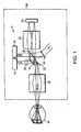
- Figure 1shows an embodiment (not falling within the present invention, but which may aid in its understanding) of an imaging apparatus 6 that can provide line scanning laser ophthalmoscope (LSLO) images and Optical Coherence Tomography (OCT) image.
- the imaging apparatus 6can be converted between a LSLO mode and a OCT mode without the use of moving parts. Instead, a system of optical elements are implemented to combine the beam paths of the OCT and the LSLO and to scan an eye 34.
- a first source 10provides a first beam of light for the OCT mode and a second source 14 provides a second beam of light for the LSLO mode.
- the imaging system 6can operate in the LSLO and the OCT mode using optical elements 18, 22, and 26.
- the beam of light from the OCT light source 10travels to a first surface of the optical element 26, which directs the light to a first surface of optical element 18.
- the linecan be redirected to optical element 22, which scans the beam of light along the retina of the eye 34.
- the lighttravels through a system of scanning lenses 38, which adjusts the focus of the light from the OCT source 10.
- the light returning from the eye 34can be descanned by the optical element 22 and directed to the first surface of the optical element 18.
- the first surface of optical element 26directs the light to a waveguide that delivers the light to a detector arm.
- the lightis dispersed by a grating 46, and the dispersed light is redirected by the second surface of the optical element 26 to an imaging lens 50 that focus the light on a detection system 54.
- a cylindrical lens 58can be used to fan out the beam of light from the LSLO source 14 into a line on the retina of the eye 34.
- the line of light from the cylindrical lens 58passes through a second surface of the optical element 18.
- Optical element 22scans the beam of light on the retina of the eye 34.
- Lenses 38can focus the light on the retina of the eye 34.
- the light returning from the eye 34can be descanned by the optical element 22 and redirected by the first surface of optical element 18.
- the lightpasses through the optical element 26, and a system of imaging lenses 50 focuses the light on the detection device 54.
- a single sourcecan be split to form the OCT source 10 and the LSLO source 14.
- the single sourcecan be switched between an LSLO mode and an OCT mode to deliver light as the LSLO source 14 or the OCT source 10, respectively.
- the OCT source 10 and the LSLO source 14are two distinct sources.
- a single broadband sourcecan be split between two input fibers, or with dual super-luminescent diode (SLD) sources 10 and 14, which can be modulated.
- a single broadband sourcecan also be switched between two input fibers, or with dual SLD sources 10 and 14 which can be modulated.
- a broadband superluminescent diodecan reduce speckle noise in an SLO image.
- Wavelength separationcan be achieved by modulating the dual-input fiber-coupled sources electronically, either as dual-SLD sources directly, or by separate fiber-optic switching or modulation of sub-bands of a single source. This approach is still compatible with single source operation, but wavelength or polarization separation can be employed, along with source-switching or modulation.
- the OCT source 10can be a near-infrared source, such as a 830-nm laser diode, an 830-nm SLD, or an 800-nm SLD with 30-nm bandwidth available from Exalos Inc.
- the LSLO source 14can be a substantially point source of light, such as an infrared laser or a super-luminescent diode.
- the LSLO source 14can be 905-nm SLD or a 920 nm SLD.
- the OCT source 10is a broadband super-luminescent diode (SLD-37MP, Superlum-Russia) with 830 nm central wavelength and approximately 50 nm bandwidth
- the LSLO source 14is a 920 nm SLD (QSDM-920-2, Q-Photonics) with about 35 nm FWHM and 2 mW output power.
- the OCT source 10is a SLD centered at 830 nm with a spectral bandwidth of about 60 nm that achieves approximately 4 ⁇ m depth resolution in the eye.
- optical element 22is a scanning mirror. In certain embodiments, optical element 22 is a dichroic beam splitter. Optical element 22 can scan and de-scan OCT light and LSLO light on or along the eye 34. In the OCT mode, optical element 22 scans one dimension of the raster scan. In the LSLO mode, optical element 22 scans a line of light along the eye 34. In some embodiments, optical element 18 is a scanning mirror. In certain embodiments, optical element 18 is a dichroic beam splitter. Optical element 18 can scan and descan OCT light on or along the eye 34. In the OCT mode, optical element 18 scans the second dimension of the retina scan. In the LSLO mode, optical element 18 can be stationary. Optical element 18 reflects LSLO light to optical element 26.
- Optical element 18can be a beam separator with an aperture.
- a dichroic beam splittercan be disposed in the aperture.
- the dichroic beam splitter in the aperturepasses the beam of light from the LSLO source through a second surface of the dichroic beam splitter to the retina of the eye.
- optical element 18can also be a beam separator that separates light directed to the eye from light returning from the eye and can redirect the light returning from the eye to the detection system.
- the dichroic beam splitterwhich can be disposed in the aperture of optical element 18 can scan, using the first surface, the beam of light along the retina of the eye in the first dimension and descan, using the first surface, the light returning from the eye in the first dimension to the detection system.
- optical element 18is used for scanning in the OCT mode, but is not used for scanning in the LSLO mode.
- optical element 26is a dichroic beam splitter that reflects OCT light in the OCT mode.
- Optical element 26can also be a dichroic beam splitter that passes LSLO light in the LSLO mode.
- the grating 46is a transmission grating.
- the grating 46can be a holographic diffraction grating (e.g., a grating available from Wasatch Photonics with 1200 lines per mm).
- the detection device 54can be a linear array detector.
- the detection devicecan be a CCD array or a CMOS detector.
- the imaging apparatus 6can run in three modes: LSLO mode only, OCT mode only, and frame-interleaved LSLO/OCT mode.
- the detection device 54can record a sequence of OCT images and LSLO images.
- no moving partsare required to change imaging modes: a simple software switch controls the hardware configuration for each imaging mode "on the fly”. When switched, the desired source can be turned on (and the other off) and the camera gain is changed if necessary, as are the transverse scan parameters of the data acquisition card.
- the LSLO and OCT systemscan be integrated in a unique manner with a common detection path that conserves sub-system capabilities and minimizes size, cost, and complexity.
- an OCT imageis recorded first.
- a LSLO imageis recorded first.
- the detection device in the OCT modereceives light returning from the eye in the first dimension and provides a first electrical responsive to the first light at a plurality of locations along a one dimensional detector.
- the electrical signalcan be combined with a reference signal from a reference arm where the first electrical signal and the reference signal is associated with an OCT image of the eye.
- the detection device in the LSLO modereceives light returning from the eye and provides a second electrical signal responsive to the second light at a plurality of locations along the one- dimensional detector.
- the second electrical signalcan be indicative of an LSLO image of the eye.
- the CCD arraycan be a line scan camera (e.g., Atmel AVIIVA M2 CL 1014 or an array available from Basler Vision Technologies).
- the CCD arraycan have 1024 detector pixels with a 14 ⁇ m pitch and can operate at a maximum 60 MHz data rate.
- the output of the cameracan be connected to a camera link board (NI PCI-1429).
- the sampled datacan be transferred continuously to computer memory.
- a ⁇ to ⁇ (or k) interpolationcan be performed.
- a discrete Fourier transformcan be performed on each set of 1024 data points acquired by the CCD array to produce an axial depth profile of the sample (A-line).
- the CMOS detectorcan be a linear array detector.
- the detectoris a 512 pixel (21 ⁇ m pitch) linear CMOS detector with active reset technology with high sensitivity and low read noise (e.g., available from Fairchild Imaging).
- the detectoris a 2048 pixel (7 ⁇ m pitch) CMOS detector with line rates to 40 kHz.
- a controlleris associated with the detection system that switches the imaging apparatus between the OCT mode and the LSLO mode.
- imaging modescan be switched fast enough to interleave LSLO and SDOCT images.
- the imagescan be interleaved at any desired rate and in any desired sequence or combination, using software control with no mechanical mode-switching transients.
- the devicecan rapidly toggle back and forth between LSLO mode and SDOCT mode frame by frame, coordinated by the scanning and signal processing electronics, e.g., to give the appearance that both operate at once: SDOCT on the forward scan, and LSLO on the flyback of the scan.
- Components of the imaging apparatus 6can be contained within a housing 60.
- the housing 60can be compact and hand-held.
- the OCT systemcan be a SDOCT.
- Figure 2demonstrates another embodiment (not falling within the present invention, but which may aid in its understanding) of a hybrid imaging apparatus 61 for imaging the eye 34.
- First optical element 18'can be a mirror 20 with a dichroic beam splitter 19 mounted in an aperture of the mirror 20.
- the dichroic beam splitter 19can be mounted on an x-axis galvanometer. When the light returns from the eye, the first surface of the optical element 18' can be used to redirect the light to the detection system 54.
- the first surface of the optical element 18'scans the light traveling to the eye 34 in a raster scan and redirects the light returning from the eye 34.
- the optical element 18'can descan the light.
- light from source 14travels through the second surface of optical element 18' to the retina of the eye.
- the lightcan travel to optical element 22 which can be driven by a galvanometer 23 that drives the optical element 22 in a direction along the y-axis.
- the scanning lenses 38can include a objective lenses 24 and an ophthalmoscopic lens 25.
- the imaging lens 50can be a system of imaging lenses.
- a plurality of objectives 51A-Dcan gather light returning from the eye in the OCT mode or the LSLO mode and direct the light to the detection system 54.
- a collimating lens 66can be used to adjust the optical elements to maximize the quality of the image.
- light from the LSLO source 14can be directed through a waveguide 67 to a coupler 68, and from the coupler 68 to a first collimating lens 66, which directs the light to the cylindrical lens 58.
- an SDOCT systemincludes light source 10 and a fiber-optic interferometer 69.
- the fiber optic interferometer 69can include a coupler 79 that receives and/or directs light to four arms: the illumination arm, the sample arm, the reference arm, and the detection arm.
- the coupleris a 50/50 or a 80/20 fiber optic beam-splitter.
- Light from the light source 10can be directed to the coupler 79 via waveguide 70.
- the coupler 79can divide the light and direct a portion to the sample arm via waveguide 74 and a portion to the reference arm via waveguide 78.
- a fraction of the light transmitted to the sample armcan be backscattered from the sample, and passed back into the coupler 79.
- a fraction of the light transmitted to the reference armcan be backscattered from an optical delay line (ODL) 80, passed back into the coupler 79.
- ODLoptical delay line
- the optical delay line 80can include a mirror placed on a translation stage and a neutral density filter that adjusts this arm's power level.
- the optical delay line 80can be placed in the reference arm to adjust the length of this arm to match the length of the sample arm.
- the polarization of the reference beamcan be adjusted with a paddle polarization controller to match the polarization of the light from the sample arm, so that polarization changes caused by bending and rotation of the optical fiber in both the sample and reference arms do not wash out the interference fringes.
- the coupler 79can mix the reference beam with the light returning from the sample arm. In some embodiments, this light passes back to the input arms, being equally split between the detector arm and the illumination arm. The light is sent to the detector arm through a waveguide 43. An isolator can be placed in the illumination arm to prevent this light from going back to the light source 10.
- Light from waveguide 74can be directed to a second collimating lens 66 via a coupler 81.
- the SDOCT systemalso includes a spectrometer system.
- the light directed to the detector arm from waveguide 43passes through coupler 82 and to a third collimating lens 66.
- the lightis dispersed by a grating 46 and received by the detection device 54.
- FIG. 3shows a schematic of the command lines, imaging raster, and timing sequence according to an illustrative embodiment (not falling within the present invention, but which may aid in its understanding) of the imaging apparatus.
- an image acquisition board (IMAQ) 86e.g., a cameralink framegrabber is used for data collection while a data acquisition (DAQ) board 90 is used for instrument timing.
- the analog output 91can be used to control galvometer(s) that control optical element 22.
- a first digital line 92can be to turn “on” and “off” any of the light sources for the OCT light source 10 or the LSLO light source 14.
- a second digital line, the real time system integration line (RTSI) 94can be used to control the camera gain.
- the IMAQ 86provides control signals 96 and receives data 97 from the detection device 54.
- the control signal 96can be a gain control for the detection device 54.
- the detection device 54is operated in a high gain mode when the imaging apparatus is operating in LSLO mode and a low gain mode when the imaging apparatus is operating in OCT mode.
- the OCTis an interferometric measurement, which functions with the least noise when the amplifying reference beam power is set to the maximum value that will not saturate the camera at its lowest gain (sensitivity) setting. This can give the maximum possible fringe amplitude (OCT signal) relative to camera noise and digitization levels.
- the LSLOis a direct imaging method that can rely on high camera sensitivity to image the weak fundus reflectance.
- the camera gain setting for the LSLOis the maximum value available that does not saturate, in order to maintain the best digital resolution over the dynamic range.
- the optimal camera gains for the OCT and the LSLOare different and require the gain to be toggled electronically between two values in switching between imaging modes so that the performance is optimized for each mode.
- the LSLO input beam powercan be set higher to account for the required sensitivity difference (e.g., up to a limit set by ANSI eye safety standards).
- the gain of camerase.g., the ATMEL line scan camera
- the timing diagram 98shows the combined LSLO/OCT mode when OCT data can be acquired.
- a comparison of the OCT source modulation 102 and the LSLO source modulation 106shows that the OCT light source is turned "on" while the LSLO source is turned “off".
- the amplitude of the y-galvanometer 110 versus the amplitude of the x- galvanometer 114 over timeis such that the y-galvanometer moves to the selected y-coordinate, and the x-galvanometer scans the OCT beam over a smaller distance.
- the distance covered by the LSLO raster scan 122is compared to the distance covered by the OCT scan 126.
- Figure 4demonstrates another embodiment (in accordance with the invention) of the imaging apparatus 128 using moveable parts to operate the apparatus in the LSLO and OCT modes.
- Figure 4shows the LSLO and OCT beams paths separated for clarity.
- the moveable partscan include a removable cylindrical lens 58 and a flip mirror 134.
- the lensmoves between a first lens position 58 and a second lens position 58' to convert between the LSLO mode and the OCT mode.
- the mirrorcan move between a first mirror position 134 and a second mirror position 134' to convert between the LSLO mode and the OCT mode.
- a single source 13can be used to supply light in both the LSLO and OCT mode.
- optical element 130allows both the OCT and LSLO beam to travel through an aperture 131.
- the optic 130can permit the returning light to pass through the same path (e.g., through the aperture 131), but in the LSLO mode, directs the beam to the detection system 54.
- a surface above, below, or surrounding the aperture 131can reflect the light in the LSLO mode.
- the optical element 130can be a mirror.
- the same detection system 54can also be used for both the LSLO and OCT modes.
- the lens 58receives a beam of light from the source 13 and provides a line of light for scanning an object.
- the beamtravels through optical element 130 to optical element 22, which scans, through a scanning lens(es) 38 the eye 34.
- the light returning from the eyecan be descanned by optical element 22 and directed to the detection device 54 by the optical element 130.
- the flip mirror 134is flipped out.
- the lens 58'In the OCT mode, in the second lens position, the lens 58' is removed from the path of the beam of light so that the source 13 provides the beam of light for scanning the object.
- the beam of lightcan travel through optical element 130 to optical element 22, which scans the light in a raster pattern over a portion of the eye 34.
- the light returning from the eyeis directed by optical element 22 to optical element 130.
- the lightcan pass back through the pupil, which functions as an interferometer.
- the lighttravels through the sample arm to the coupler 79, which mixes the beam with the light from a reference arm as shown in Figures 2-3 . A part of the mixed beam from the coupler 79 is sent to the detector arm where the beam is dispersed by the grating 46.
- the flip mirror 134'directs the light dispersed by the grating 46 to the detection device 54.
- the systemcan operate as a high-resolution 30 fps SDOCT scanner showing cross-sectional image of the retina at selected planes.
- the SLD beamcan be fanned into a focused line, and the system can be converted into a quasi-confocal LSLO en face wide-field retinal imager.
- the actuated cylindrical lens 58 and mirror 134permit mode switching within less than about 1 frame period.
- the SLD source modulecan be integrated into the optics package.
- a tethercan be used connect to an external source and power module.
- batteriescan be used.
- Figure 5shows another illustrative embodiment (in accordance with the invention) of an imaging apparatus 138 that includes moveable parts to convert between an OCT mode and an LSLO mode.
- the same light source 13 and detection system 54can be used for both the OCT mode and LSLO mode.
- Light source 13directs light to coupler 140 via waveguide 142 in the sample arm.
- the coupler 140directs light to the lens 58, which directs light to optical element 144.
- Optical element 144directs light to optical element 22, which can scan the beam of radiation on the eye 34, Light returning from the eye 34 passes by and/or around optical element 144 and through pupil stop 146.
- Flip mirror 134is removed from the optical path.
- lens 58In the OCT mode, lens 58 is in position 58' (e.g., it is removed from the beam path). The light is directed by optical element 144 to optical element 22. Light returning from the eye 34 is reflected by optical element 144 back into waveguide 142. The light emerges from waveguide 43 and is dispersed by grating 46 before it is reflected by mirror 134 to the detection device 54.
- Optical element 144can be a mirror or prism.
- Optical element 146can be a pupil stop and/or a pupil aperture.
- the subdivision of the pupil aperturecan allow the efficient integration of the subsystems and elimination of unwanted reflections (e.g., corneal reflections).
- the scanning optical delay in the OCT reference arm 78compensates for pupil position, eye length and/or focus. With a flip mirror 134, both imaging systems can use the same linear array detector 54.
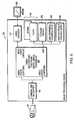
- FIG. 6shows a block diagram of an exemplary chipset 160.
- a stand-alone FPGA/DSP electronics platforme.g., not tethered to a PC
- the chipset 160can include a camera link 164, a signal processor 168, a video encoder 172, memory 176, a storage module 180, a USB controller 184, and a user interface 188.
- the camera link 164can be coupled to the detection device 54.
- the video encodercan be coupled to a display device 192.
- the memory 176can be SDRAM, flash memory, and/or any other suitable memory.
- the storage device 180can be a compact flash, smart media, SD, or MMC.
- the USB controllercan include a USB interface.
- the user interface 188 and display device 192can display an LSLO image and a OCT image separately or simultaneously (depending on the imaging mode), and the OCT scan can be positioned anywhere in the LSLO raster.
- Other controls for OCT processing, display, and saving or streaming to diskare in a tab box in the display.
- the raw spectrum and processed profilecan be shown, and the integrated fixation target can be displayed.
- an FPGA camera board with integrated SVGA LCD display driver for a CMOS line arraycan obviate the need for a PC and frame grabber tethered to the optical scanner head.
- real time FFTs on SDOCT line scan data and displaycan be performed using the signal processor chipset 168 (e.g., a DM642 fixed-point DSP or an FPGA).
- the detection device 54can be connected to the signal processor via camera-link RX Chipset 164.
- a suitable signal processing approach or algorithm with associated hardware and software for SDOCT signal processing algorithmcan include such an interpolation to k-space process. Dispersion compensation can be incorporated in the software for real time operation.
- LSLO-guided 2D SDOCT sections and localized 3D (micro-scan) SDOCT imaging modalitiescan be used as part of the imaging mode control software.
- the operatorcan precisely scan selected retinal features at the desired resolution.
- 3D structurecan be visualized by sweeping the line scan manually push broom-style.
- local 3D imagescan be captured and displayed (e.g., a micro-scan option).
- a resonant scanneris used to perform a low speed, small amplitude scan.
- the resonant scannercan be added to the SDOCT beam path, orthogonal to the main galvo scanner. Instead of performing a single long linear scan of 5 mm or more when a very small feature such as a laser lesion is of interest, the system can be commanded to perform many smaller scans in a raster pattern: perhaps twenty or more 0.5 mm B-scans with 10 micron pixellation in x (50 A-scans) and 25 ⁇ m pixels in y (20 B-scans).
- the entire rastercan include 1000 A-scans, which can be displayed as one composite B-scan.
- 500 x 500 micron x 2 mm high-resolution SDOCT volume imagescan be provided.
- Such an approachcan be used for elucidating columnar laser damage or localized pathology.
- a fiducial boxcan be overlaid in the live LSLO image for this selectable mode, with real time display of the successive SDOCT stripe images.
- Estimates of 3D micro-scan speedcan be obtained from digital signal processor benchmark data.
- the 1024 point FFT benchmark for the DM642is less than about 16 ⁇ s per FFT.
- the CCD array or CMOS detectorcan have line rates in excess of 25 Klps. At this line rate, the resulting frame rate for 1000 A-scans of the Micro-scan raster (50 x 20) is about 25fps (0.04 sec/frame).
- Real time 3D micro-scans with rapid intuitive display of 3D datacan be performed.
- a FPGA signal processoris utilized to provide a scan showing local 3D structures.
Landscapes
- Health & Medical Sciences (AREA)
- Life Sciences & Earth Sciences (AREA)
- Physics & Mathematics (AREA)
- General Health & Medical Sciences (AREA)
- General Physics & Mathematics (AREA)
- Medical Informatics (AREA)
- Surgery (AREA)
- Engineering & Computer Science (AREA)
- Biomedical Technology (AREA)
- Heart & Thoracic Surgery (AREA)
- Biophysics (AREA)
- Molecular Biology (AREA)
- Ophthalmology & Optometry (AREA)
- Animal Behavior & Ethology (AREA)
- Radiology & Medical Imaging (AREA)
- Public Health (AREA)
- Veterinary Medicine (AREA)
- Nuclear Medicine, Radiotherapy & Molecular Imaging (AREA)
- Eye Examination Apparatus (AREA)
- Investigating Or Analysing Materials By Optical Means (AREA)
Description
- This invention relates generally to optical imaging, and more particularly, to a device that combines a line-scanning laser ophthalmoscope and a spectral domain optical coherence tomography system for retinal imaging.
- Fundus and retinal imaging are important diagnostics in ophthalmology. Advanced imaging technologies now exist to detect tissue changes that occur due to retinal injuries not discernable with fundus photography. For example, optical coherence tomography (OCT) can provide depth-resolved images of ocular tissues approaching cellular resolution. The confocal scanning laser ophthalmoscope (SLO) also plays an important role in high-contrast visualization of thermal and other damage near sensitive retinal anatomy (e.g., the fovea).
- OCT is an emerging technology for micrometer-scale, cross-sectional imaging of biological tissue and materials. A major application of OCT is ophthalmic imaging of the human retinain vivo. The Spectral-Domain OCT (SDOCT) improvement of the traditional time domain OCT (TDOCT) technique, known also as Fourier domain OCT (FDOCT), makes this technology suitable for real-time cross-sectional retinal imaging at video rate. At high speed, the need for vertical realignment of "A-scan" depth profiles is effectively eliminated across single B-scans, revealing a truer representation of retinal topography and the optic nerve head. Although B-scan image distortion by involuntary eye movement is reduced, transverse eye motion remains an issue for 3-D imaging and individual scan registration. Stabilized 3D OCT imaging can provide anen face fundus views for locating any given B-scan relative to retinal landmarks. Alternatively, simultaneous or interleaved live fundus imaging can also provide good retinal coordinates for a given B-scan, subject to the limitations of inter-frame eye motion.
- The fusion of wide-field, line scanning laser ophthalmoscope (LSLO) retinal imaging with SDOCT imaging can enhance the clinician's ability to quickly assess pathologies in linked, complementary views with a simple, compact instrument. To make the ocular interface of future SDOCT systems more efficient, cost-effective, compact, and eventually field portable, neither complex motion stabilization systems nor opto-mechanical integration of secondary fundus cameras are desirable. Yet without precise knowledge of the OCT scan coordinates within the live fundus image to guide scan acquisition and interpretation, the diagnostic utility of this powerful imaging modality is limited.
- The model for most clinical imaging systems to date has been the large stationary, desk-sized platforms with slit-lamp style human interface, bulky enclosure, numerous secondary optical or physical adjustment features, tethered power conditioning and signal processing units, computer, mouse and keyboard, and CRT monitor. These units generally require the subjects to adapt their posture to the instruments, rather than vice-versa. They typically combine the user interface and image acquisition functions with the image processing functions, the image analysis functions and the patient database. What is needed is an imaging system that can adapt to the patient, one where the operator, technician or medic can gather data, and an eye injury expert can provide analysis remotely based on the data recorded.
- We are aware of Japanese patent publication
JP11-253403 - According to the invention, we provide an optical apparatus according to
claim 1, and a method according toclaim 5. Optional features are recited in the dependent claims. - The invention, in one embodiment, features a system to provide images of the retina of an eye using a single compact instrument. The retinal imaging system can be a combination of an OCT system (e.g., a SDOCT system) and a LSLO system. In some embodiments, the SDOCT and LSLO share the same imaging optics and line scan camera for both OCT and LSLO imaging modes. Co-registered high contrast wide-field en face retinal LSLO and SDOCT images can be obtained non-mydriatically with less than 600 microwatts of broadband illumination at 15 frames/sec. The LSLO/SDOCT hybrid instrument can have important applications in clinical ophthalmic diagnostics and emergency medicine. The fusion of the wide-field, LSLO retinal imaging with SDOCT imaging can enhance the clinician's ability to quickly assess pathologies in linked, complementary views with a simple, compact instrument. Knowledge of the OCT scan coordinates within the live fundus image to guide scan acquisition and interpretation can enhance the diagnostic utility of OCT. For example, non-mydriatic, live retinal imaging (no pupil dilation), which requires no more than a 3 mm pupil in the human eye, usually depends on the use of NIR illumination to inhibit the pupil closure reflex. This is the case for the broadband SLD illumination beam from 800 nm to 900 nm, which for most subjects is still visible at < 1 mW, but not bright or aversive, and allows imaging through a natural 2 to 3 mm pupil under subdued lighting conditions. The integration of hand-held LSLO technology with SDOCT can use the 3 mm pupil of the eye in two ways. First, the central 1 mm portion of the pupil is used as the SLD beam entrance pupil for both subsystems, but the exit pupils are separated. The returning light of the SDOCT passes back though the same 1 mm pupil, to function as an interferometer. The LSLO system can use the 3 mm annular aperture surrounding the central pupil area as its exit pupil for imaging the scattered light from the retina, thereby also avoiding corneal reflections from the entrance pupil. Second, the left and right sub-apertures of the LSLO annular aperture can be imaged to left and right detector arrays in order to form an LSLO stereo pair. This may be useful for direct visual assessment of gross retinal features and damage such as retinal hemorrhage.
- In one aspect, there is an apparatus that includes a housing and a system of optical components disposed in the housing. The optical components are capable of operating in a LSLO mode and an OCT mode. The optical components include a first source to provide a first beam of light for the OCT mode, a second source to provide a second beam of light for the LSLO mode, and a first optic. In the OCT mode, the first optic scans, using a first surface of the first optic, the first beam of light along a retina of an eye in a first dimension and descans using the first surface, a first light returning from the eye in the first dimension to a detection system. In the LSLO mode, the first optic passes the second beam of light to the retina of the eye through a second surface of the first optic.
- In another aspect, there is an apparatus that includes a housing and a system of optical components disposed in the housing capable of operating in an LSLO mode and an OCT mode. The system of optical components includes a first optic. In the OCT mode, the first optic redirects, using a first surface of the optic, a beam of light from a first source to an object to be scanned. The first optic also uses the first surface to redirect light returning from the object scanned. A second surface of the first optic redirects light dispersed by a grating to a detection system. In the LSLO mode, the first optic passes light returning from the object scanned to the detection system.
- In another aspect, there is a method for imaging a retina of an eye. The method includes acquiring an OCT image of the eye by receiving, on a one-dimensional detector, a first light returning from the eye. A first electrical signal responsive to the first light is provided at each of a plurality of locations along the one-dimensional detector. The first electrical signal is combined with a reference signal from a reference arm. The first electrical signal and the reference signal is associated with the OCT image of the eye. In the LSLO mode, the method includes acquiring a LSLO image of the eye by receiving, on the one-dimensional detector, a second light returning from the eye. A second electrical signal is provided which is responsive to the second light at each of a plurality of locations along the one-dimensional detector. The second electrical signal is indicative of the LSLO image of the eye. The method also includes interleaving acquisition of the OCT image of the eye and the LSLO image of the eye.
- In yet another aspect, there is an optical apparatus including a line scanning laser ophthalmoscope (LSLO) mode and an optical coherence tomography (OCT) mode. The optical apparatus includes a first source of a beam of light suitable for use in the LSLO mode and a second source of a beam of light suitable for use in the OCT mode. A lens receives the beam of light from the first source and provides a line of light for use in the LSLO mode. The apparatus also includes an optic. In the OCT mode, the optic redirects a beam of light from the second source to an object to be scanned, using a first surface of the optic. The optic uses the first surface to redirect the light returning from the object scanned and uses the second surface of the optic to redirect light dispersed into an OCT line configuration by a grating to a detection system. In the LSLO mode, the optic passes light returning from the object scanned to the detection system. The optic apparatus also includes a scanner. In the LSLO mode, the scanner scans a first portion of an object with the line of light in a direction perpendicular to the line through at least one lens. The scanner also descans light returning from the object in a LSLO line configuration. In the OCT mode, the scanner scans a second portion of the object with the beam of light and redirects light returning from the object. The detection system includes a one-dimensional detector. In the LSLO mode, the detection system receives the light descanned from the object and provides an electrical signal responsive to the light descanned at each of a plurality of locations along the LSLO line configuration. The electrical signal is indicative of a LSLO image of the object. In the OCT mode, the detection system receives the light redirected from the mirror and provides an electrical signal responsive to the light redirected at each of a plurality of locations along the OCT line configuration. The detection system combines the electrical signal with a reference signal from a reference arm. The electrical signal and the reference signal is associated with an OCT image of the object.
- In another aspect, there is a method of imaging a retina of an eye. The method includes combining an optical path of an OCT imager and an optical path of a LSLO imager using a system of optics. A single detector is used to switch between an OCT mode and a LSLO mode. The method also acquires images of the retina while switching between the OCT mode and the LSLO mode.
- In another aspect, there is an optical apparatus that includes a housing and a system of optical components disposed in the housing capable of operating in a line scanning laser ophthalmoscope (LSLO) mode and an optical coherence tomography (OCT) mode. The system of optical components includes a lens for converting between the LSLO mode and the OCT mode. The lens is movable between a first lens position and a second lens position. In the first lens position, the lens receives a beam of light from a source and provides a line of light for scanning an object in the LSLO mode. In the second lens position, the lens removed from a path of the beam of light so that the source provides the beam of light for scanning the object in the OCT mode. The optical apparatus also includes a mirror for converting between the LSLO mode and the OCT mode. The mirror is movable between a first mirror position and a second mirror position. In the first position, the mirror is removed from a path of light returning from the object. In the second position, the mirror receives the light returning from the object.
- In other examples, any of the aspects above, or any apparatus or method described herein, can include one or more of the following features.
- In some embodiments, the first optic includes a beam separator having an aperture that, in the LSLO mode, redirects the second light returning from the eye to the detection system. In some embodiments, the optical system can include a dichroic beamsplitter. In some embodiments, the first optic is a dichroic beam splitter. The dichroic beam splitter can be disposed in the aperture. In the OCT mode, the dichroic beam splitter disposed in the aperature uses the first surface of the dichroic beam splitter to scan the first beam of light along the retina of the eye in the first dimension and uses the first surface to descan the first light returning from the eye in the first dimension to the detection system. In the LSLO mode the second beam of light to the retina of the eye passes through the second surface of the dichroic beam splitter.
- In some embodiments, the system of optical components also includes a second optic that, in the OCT mode, scans the first beam of light along the retina in a second dimension and descans the first light returning from the eye in the second dimension. The second optic can direct the first light returning from the eye to the first surface of the first optic and to the detection system. In the LSLO mode, the second optic can scan the second beam of light, in a line focus configuration, along the retina in the second dimension, and descan the second light returning from the eye in the second dimension. The second optic can direct the light returning from the eye to the first surface of the first optic and to the detection system. In some embodiments, the second optic includes a scanning mirror.
- In some embodiments, the system of optical components also includes a third optic. In the OCT mode, the third optic can use a first surface of the third optic to direct the first beam of light to the first optic. The third optic can also use the first surface of the first optic to redirect the first light returning from the eye scanned. In some embodiments, the third optic uses a second surface of the third optic to redirect the first light, dispersed by a grating, to the detection system. In the LSLO mode, the third optic can pass the second light returning from the eye to the detection system. The third optic can include a dichroic beam splitter.
- In some embodiments, the housing is adapted to be handheld. The first source and the second source can be the same source of light. In some embodiments, the imaging apparatus includes a controller, associated with the detection system, that switches the apparatus between the OCT and the LSLO mode. The controller associated with the detection system can also interleave the acquisition of the OCT image of the eye and the LSLO image of the eye by the detection system. In some embodiments, the OCT mode includes a spectral domain OCT mode.
- In some embodiments, the system of optical components can include a scanner. In the LSLO mode, the scanner can scan through at least one lens, a first portion of the object with the line of light in a direction perpendicular to the line. The scanner can also descan light returning from the object in the LSLO line configuration. In the OCT mode, the scanner can scan a second portion of the object with the beam of light and redirect light returning from the object.
- In some embodiments, the system of optical components includes a grating spectrograph, used only in the OCT mode, to disperse light returning from the object into an OCT line configuration.
- The apparatus can have a first and second source of light that generates a first and second light beam. The first and second light beam can be used for the LSLO mode and the OCT mode, respectively. In some embodiments, the detection system includes a one-dimensional detector. In the OCT mode, the one dimensional detector can receive the first light returning from the eye in the first dimension and provide a first electrical signal responsive to the first light at each of a plurality of locations along the one-dimensional detector. The first electrical signal can be combined with a reference signal from a reference arm. In some embodiments, the first electrical signal and the reference signal is associated with an OCT image of the eye. In the LSLO mode, the one dimensional detector can receive a second light returning from the eye and provide a second electrical signal responsive to the second light at each of a plurality of locations along the one-dimensional detector. In some embodiments, the second electrical signal is indicative of a LSLO image of the eye.
- In some embodiments, the system of optical components includes a source of the beam of light used in the LSLO mode and the OCT mode. The detection system can include a one-dimensional detector. In the LSLO mode, the detector can receive light descanned from the object and provide an electrical signal responsive to the light descanned at each ofa plurality of locations along a LSLO line configuration. In some embodiments, the electrical signal is indicative of a LSLO image of the object. In the OCT mode, the detector can receive light redirected by the mirror and provide an electrical signal responsive to the light redirected at each of a plurality of locations along an OCT line configuration. The electrical signal can be combined with a reference signal from a reference arm. In some embodiments, the electrical signal and the reference signal is associated with an OCT image of the object.
- In some embodiments, the apparatus includes a controller, associated with the detection system, that switches the apparatus between the OCT mode and the LSLO mode. The controller, associated with the detection system, can interleave acquisition of the OCT image of the eye and the LSLO image of the eye by the detection system. In some embodiments, the controller can interleave a first series of images of the retina acquired in the OCT mode and a second series of images of the retina acquired in the LSLO mode.
- Other aspects and advantages of the invention can become apparent from the following drawings and description, all of which illustrate the principles of the invention, by way of example only.
- The advantages of the invention described above, together with further advantages, may be better understood by referring to the following description taken in conjunction with the accompanying drawings. The drawings are not necessarily to scale, emphasis instead generally being placed upon illustrating the principles of the invention.
Figure1 is a schematic drawing of a hybrid OCT/LSLO retinal imaging system.Figure2 is another schematic drawing of a hybrid OCT/LSLO retinal imaging system.Figure3 is a schematic drawing of the command lines, imaging raster, and timing sequence of a hybrid OCT/LSLO retinal imaging system.Figure4 is a schematic drawing of an apparatus that uses moving parts to convert between the OCT mode and the LSLO mode, according to an illustrative embodiment of the invention.Figure 5 is another schematic drawing of an apparatus that uses moving parts to convert between the OCT mode and the LSLO mode.Figure 6 is a block diagram of an exemplary chipset for use in a hybrid OCT/LSLO retinal imaging system.Figure 1 shows an embodiment (not falling within the present invention, but which may aid in its understanding) of an imaging apparatus 6 that can provide line scanning laser ophthalmoscope (LSLO) images and Optical Coherence Tomography (OCT) image. The imaging apparatus 6 can be converted between a LSLO mode and a OCT mode without the use of moving parts. Instead, a system of optical elements are implemented to combine the beam paths of the OCT and the LSLO and to scan aneye 34. Afirst source 10 provides a first beam of light for the OCT mode and asecond source 14 provides a second beam of light for the LSLO mode. The imaging system 6 can operate in the LSLO and the OCT mode usingoptical elements - When the imaging apparatus 6 is operating in the OCT mode, the beam of light from the OCT
light source 10 travels to a first surface of theoptical element 26, which directs the light to a first surface ofoptical element 18. The line can be redirected tooptical element 22, which scans the beam of light along the retina of theeye 34. In some embodiments, the light travels through a system ofscanning lenses 38, which adjusts the focus of the light from theOCT source 10. The light returning from theeye 34 can be descanned by theoptical element 22 and directed to the first surface of theoptical element 18. The first surface ofoptical element 26 directs the light to a waveguide that delivers the light to a detector arm. The light is dispersed by a grating 46, and the dispersed light is redirected by the second surface of theoptical element 26 to animaging lens 50 that focus the light on adetection system 54. - When the imaging apparatus 6 is operating in the LSLO mode, a
cylindrical lens 58 can be used to fan out the beam of light from theLSLO source 14 into a line on the retina of theeye 34. The line of light from thecylindrical lens 58 passes through a second surface of theoptical element 18.Optical element 22 scans the beam of light on the retina of theeye 34.Lenses 38 can focus the light on the retina of theeye 34. The light returning from theeye 34 can be descanned by theoptical element 22 and redirected by the first surface ofoptical element 18. In the LSLO mode, the light passes through theoptical element 26, and a system ofimaging lenses 50 focuses the light on thedetection device 54. - In some embodiments, a single source can be split to form the
OCT source 10 and theLSLO source 14. The single source can be switched between an LSLO mode and an OCT mode to deliver light as theLSLO source 14 or theOCT source 10, respectively. In some embodiments, theOCT source 10 and theLSLO source 14 are two distinct sources. - A single broadband source can be split between two input fibers, or with dual super-luminescent diode (SLD)
sources dual SLD sources - The
OCT source 10 can be a near-infrared source, such as a 830-nm laser diode, an 830-nm SLD, or an 800-nm SLD with 30-nm bandwidth available from Exalos Inc. TheLSLO source 14 can be a substantially point source of light, such as an infrared laser or a super-luminescent diode. For example theLSLO source 14 can be 905-nm SLD or a 920 nm SLD. In one embodiment, theOCT source 10 is a broadband super-luminescent diode (SLD-37MP, Superlum-Russia) with 830 nm central wavelength and approximately 50 nm bandwidth, and theLSLO source 14 is a 920 nm SLD (QSDM-920-2, Q-Photonics) with about 35 nm FWHM and 2 mW output power. In some embodiments, theOCT source 10 is a SLD centered at 830 nm with a spectral bandwidth of about 60 nm that achieves approximately 4 µm depth resolution in the eye. - In some embodiments,
optical element 22 is a scanning mirror. In certain embodiments,optical element 22 is a dichroic beam splitter.Optical element 22 can scan and de-scan OCT light and LSLO light on or along theeye 34. In the OCT mode,optical element 22 scans one dimension of the raster scan. In the LSLO mode,optical element 22 scans a line of light along theeye 34. In some embodiments,optical element 18 is a scanning mirror. In certain embodiments,optical element 18 is a dichroic beam splitter.Optical element 18 can scan and descan OCT light on or along theeye 34. In the OCT mode,optical element 18 scans the second dimension of the retina scan. In the LSLO mode,optical element 18 can be stationary.Optical element 18 reflects LSLO light tooptical element 26. Optical element 18 can be a beam separator with an aperture. A dichroic beam splitter can be disposed in the aperture. In the LSLO mode, the dichroic beam splitter in the aperture passes the beam of light from the LSLO source through a second surface of the dichroic beam splitter to the retina of the eye. When operating in the LSLO mode,optical element 18 can also be a beam separator that separates light directed to the eye from light returning from the eye and can redirect the light returning from the eye to the detection system. In the OCT mode, the dichroic beam splitter, which can be disposed in the aperture ofoptical element 18 can scan, using the first surface, the beam of light along the retina of the eye in the first dimension and descan, using the first surface, the light returning from the eye in the first dimension to the detection system. In a preferred embodiment,optical element 18 is used for scanning in the OCT mode, but is not used for scanning in the LSLO mode.- In some embodiments,
optical element 26 is a dichroic beam splitter that reflects OCT light in the OCT mode.Optical element 26 can also be a dichroic beam splitter that passes LSLO light in the LSLO mode. - In some embodiments, the grating 46 is a transmission grating. The grating 46 can be a holographic diffraction grating (e.g., a grating available from Wasatch Photonics with 1200 lines per mm). The
detection device 54 can be a linear array detector. For example, the detection device can be a CCD array or a CMOS detector. - The imaging apparatus 6 can run in three modes: LSLO mode only, OCT mode only, and frame-interleaved LSLO/OCT mode. The
detection device 54 can record a sequence of OCT images and LSLO images. In some embodiments, no moving parts are required to change imaging modes: a simple software switch controls the hardware configuration for each imaging mode "on the fly". When switched, the desired source can be turned on (and the other off) and the camera gain is changed if necessary, as are the transverse scan parameters of the data acquisition card. Thus, the LSLO and OCT systems can be integrated in a unique manner with a common detection path that conserves sub-system capabilities and minimizes size, cost, and complexity. - In some embodiments, an OCT image is recorded first. In other embodiments, a LSLO image is recorded first. In some embodiments, the detection device in the OCT mode receives light returning from the eye in the first dimension and provides a first electrical responsive to the first light at a plurality of locations along a one dimensional detector. The electrical signal can be combined with a reference signal from a reference arm where the first electrical signal and the reference signal is associated with an OCT image of the eye. In some embodiments, the detection device in the LSLO mode receives light returning from the eye and provides a second electrical signal responsive to the second light at a plurality of locations along the one- dimensional detector. The second electrical signal can be indicative of an LSLO image of the eye.
- The CCD array can be a line scan camera (e.g., Atmel AVIIVA M2 CL 1014 or an array available from Basler Vision Technologies). The CCD array can have 1024 detector pixels with a 14 µm pitch and can operate at a maximum 60 MHz data rate. The output of the camera can be connected to a camera link board (NI PCI-1429). The sampled data can be transferred continuously to computer memory. A λ to ω (or k) interpolation can be performed. A discrete Fourier transform can be performed on each set of 1024 data points acquired by the CCD array to produce an axial depth profile of the sample (A-line).
- The CMOS detector can be a linear array detector. In one embodiment, the detector is a 512 pixel (21 µm pitch) linear CMOS detector with active reset technology with high sensitivity and low read noise (e.g., available from Fairchild Imaging). In one embodiment, the detector is a 2048 pixel (7 µm pitch) CMOS detector with line rates to 40 kHz.
- In some embodiments, a controller is associated with the detection system that switches the imaging apparatus between the OCT mode and the LSLO mode. In some embodiments, imaging modes can be switched fast enough to interleave LSLO and SDOCT images. The images can be interleaved at any desired rate and in any desired sequence or combination, using software control with no mechanical mode-switching transients. The device can rapidly toggle back and forth between LSLO mode and SDOCT mode frame by frame, coordinated by the scanning and signal processing electronics, e.g., to give the appearance that both operate at once: SDOCT on the forward scan, and LSLO on the flyback of the scan.
- Components of the imaging apparatus 6 can be contained within a
housing 60. In some embodiments, thehousing 60 can be compact and hand-held. The OCT system can be a SDOCT. Figure 2 demonstrates another embodiment (not falling within the present invention, but which may aid in its understanding) of ahybrid imaging apparatus 61 for imaging theeye 34. First optical element 18' can be a mirror 20 with adichroic beam splitter 19 mounted in an aperture of the mirror 20. Thedichroic beam splitter 19 can be mounted on an x-axis galvanometer. When the light returns from the eye, the first surface of the optical element 18' can be used to redirect the light to thedetection system 54.- In the OCT mode, the first surface of the optical element 18' scans the light traveling to the
eye 34 in a raster scan and redirects the light returning from theeye 34. The optical element 18' can descan the light. In the LSLO mode, light fromsource 14 travels through the second surface of optical element 18' to the retina of the eye. The light can travel tooptical element 22 which can be driven by agalvanometer 23 that drives theoptical element 22 in a direction along the y-axis. Thescanning lenses 38 can include aobjective lenses 24 and anophthalmoscopic lens 25. - The
imaging lens 50 can be a system of imaging lenses. For example, a plurality ofobjectives 51A-D can gather light returning from the eye in the OCT mode or the LSLO mode and direct the light to thedetection system 54. - A collimating
lens 66 can be used to adjust the optical elements to maximize the quality of the image. In the LSLO mode, light from theLSLO source 14 can be directed through a waveguide 67 to a coupler 68, and from the coupler 68 to afirst collimating lens 66, which directs the light to thecylindrical lens 58. - In some embodiments, an SDOCT system includes
light source 10 and a fiber-optic interferometer 69. Thefiber optic interferometer 69 can include acoupler 79 that receives and/or directs light to four arms: the illumination arm, the sample arm, the reference arm, and the detection arm. In some embodiments, the coupler is a 50/50 or a 80/20 fiber optic beam-splitter. Light from thelight source 10 can be directed to thecoupler 79 viawaveguide 70. Thecoupler 79 can divide the light and direct a portion to the sample arm viawaveguide 74 and a portion to the reference arm viawaveguide 78. A fraction of the light transmitted to the sample arm can be backscattered from the sample, and passed back into thecoupler 79. A fraction of the light transmitted to the reference arm can be backscattered from an optical delay line (ODL) 80, passed back into thecoupler 79. - The
optical delay line 80 can include a mirror placed on a translation stage and a neutral density filter that adjusts this arm's power level. Theoptical delay line 80 can be placed in the reference arm to adjust the length of this arm to match the length of the sample arm. The polarization of the reference beam can be adjusted with a paddle polarization controller to match the polarization of the light from the sample arm, so that polarization changes caused by bending and rotation of the optical fiber in both the sample and reference arms do not wash out the interference fringes. Thecoupler 79 can mix the reference beam with the light returning from the sample arm. In some embodiments, this light passes back to the input arms, being equally split between the detector arm and the illumination arm. The light is sent to the detector arm through awaveguide 43. An isolator can be placed in the illumination arm to prevent this light from going back to thelight source 10. Light fromwaveguide 74 can be directed to asecond collimating lens 66 via acoupler 81. - The SDOCT system also includes a spectrometer system. The light directed to the detector arm from
waveguide 43 passes throughcoupler 82 and to athird collimating lens 66. The light is dispersed by a grating 46 and received by thedetection device 54. Figure 3 shows a schematic of the command lines, imaging raster, and timing sequence according to an illustrative embodiment (not falling within the present invention, but which may aid in its understanding) of the imaging apparatus. In some embodiments, an image acquisition board (IMAQ) 86 e.g., a cameralink framegrabber is used for data collection while a data acquisition (DAQ)board 90 is used for instrument timing. Theanalog output 91 can be used to control galvometer(s) that controloptical element 22. A firstdigital line 92 can be to turn "on" and "off" any of the light sources for the OCTlight source 10 or the LSLOlight source 14. A second digital line, the real time system integration line (RTSI) 94 can be used to control the camera gain. TheIMAQ 86 provides control signals 96 and receivesdata 97 from thedetection device 54. Thecontrol signal 96 can be a gain control for thedetection device 54.- In certain embodiments, the
detection device 54 is operated in a high gain mode when the imaging apparatus is operating in LSLO mode and a low gain mode when the imaging apparatus is operating in OCT mode. The OCT is an interferometric measurement, which functions with the least noise when the amplifying reference beam power is set to the maximum value that will not saturate the camera at its lowest gain (sensitivity) setting. This can give the maximum possible fringe amplitude (OCT signal) relative to camera noise and digitization levels. The LSLO is a direct imaging method that can rely on high camera sensitivity to image the weak fundus reflectance. In some embodiments, the camera gain setting for the LSLO is the maximum value available that does not saturate, in order to maintain the best digital resolution over the dynamic range. In some embodiments, the optimal camera gains for the OCT and the LSLO are different and require the gain to be toggled electronically between two values in switching between imaging modes so that the performance is optimized for each mode. Alternatively, the LSLO input beam power can be set higher to account for the required sensitivity difference (e.g., up to a limit set by ANSI eye safety standards). The gain of cameras (e.g., the ATMEL line scan camera) can be changed with serial digital commands, or more directly with digital control signals synchronized to the frame rates. - The timing diagram 98 shows the combined LSLO/OCT mode when OCT data can be acquired. A comparison of the
OCT source modulation 102 and theLSLO source modulation 106 shows that the OCT light source is turned "on" while the LSLO source is turned "off". In some embodiments, the amplitude of the y-galvanometer 110 versus the amplitude of the x-galvanometer 114 over time is such that the y-galvanometer moves to the selected y-coordinate, and the x-galvanometer scans the OCT beam over a smaller distance. In diagram 118, the distance covered by theLSLO raster scan 122 is compared to the distance covered by the OCT scan 126. Figure 4 demonstrates another embodiment (in accordance with the invention) of theimaging apparatus 128 using moveable parts to operate the apparatus in the LSLO and OCT modes.Figure 4 shows the LSLO and OCT beams paths separated for clarity. The moveable parts can include a removablecylindrical lens 58 and aflip mirror 134. The lens moves between afirst lens position 58 and a second lens position 58' to convert between the LSLO mode and the OCT mode. The mirror can move between afirst mirror position 134 and a second mirror position 134' to convert between the LSLO mode and the OCT mode.- A
single source 13 can be used to supply light in both the LSLO and OCT mode. In some embodiments,optical element 130 allows both the OCT and LSLO beam to travel through anaperture 131. In the OCT mode, the optic 130 can permit the returning light to pass through the same path (e.g., through the aperture 131), but in the LSLO mode, directs the beam to thedetection system 54. For example, a surface above, below, or surrounding theaperture 131 can reflect the light in the LSLO mode. Theoptical element 130 can be a mirror. Thesame detection system 54 can also be used for both the LSLO and OCT modes. - In the LSLO mode, in the first lens position, the
lens 58 receives a beam of light from thesource 13 and provides a line of light for scanning an object. The beam travels throughoptical element 130 tooptical element 22, which scans, through a scanning lens(es) 38 theeye 34. The light returning from the eye can be descanned byoptical element 22 and directed to thedetection device 54 by theoptical element 130. In the LSLO mode, theflip mirror 134 is flipped out. - In the OCT mode, in the second lens position, the lens 58' is removed from the path of the beam of light so that the
source 13 provides the beam of light for scanning the object. The beam of light can travel throughoptical element 130 tooptical element 22, which scans the light in a raster pattern over a portion of theeye 34. The light returning from the eye is directed byoptical element 22 tooptical element 130. The light can pass back through the pupil, which functions as an interferometer. The light travels through the sample arm to thecoupler 79, which mixes the beam with the light from a reference arm as shown inFigures 2-3 . A part of the mixed beam from thecoupler 79 is sent to the detector arm where the beam is dispersed by thegrating 46. In the OCT mode, the flip mirror 134' directs the light dispersed by the grating 46 to thedetection device 54. - Without the cylindrical lens 58' in the beam path and the mirror 134' flipped in, the system can operate as a high-resolution 30 fps SDOCT scanner showing cross-sectional image of the retina at selected planes. With the
lens 58 in place and themirror 134 flipped out, the SLD beam can be fanned into a focused line, and the system can be converted into a quasi-confocal LSLO en face wide-field retinal imager. In some embodiments, the actuatedcylindrical lens 58 andmirror 134 permit mode switching within less than about 1 frame period. The SLD source module can be integrated into the optics package. A tether can be used connect to an external source and power module. In certain embodiments, batteries can be used. Figure 5 shows another illustrative embodiment (in accordance with the invention) of animaging apparatus 138 that includes moveable parts to convert between an OCT mode and an LSLO mode. The samelight source 13 anddetection system 54 can be used for both the OCT mode and LSLO mode.Light source 13 directs light tocoupler 140 viawaveguide 142 in the sample arm.- In the LSLO mode, the
coupler 140 directs light to thelens 58, which directs light tooptical element 144.Optical element 144 directs light tooptical element 22, which can scan the beam of radiation on theeye 34, Light returning from theeye 34 passes by and/or aroundoptical element 144 and throughpupil stop 146.Flip mirror 134 is removed from the optical path. - In the OCT mode,
lens 58 is in position 58' (e.g., it is removed from the beam path). The light is directed byoptical element 144 tooptical element 22. Light returning from theeye 34 is reflected byoptical element 144 back intowaveguide 142. The light emerges fromwaveguide 43 and is dispersed by grating 46 before it is reflected bymirror 134 to thedetection device 54. Optical element 144 can be a mirror or prism.Optical element 146 can be a pupil stop and/or a pupil aperture. The subdivision of the pupil aperture can allow the efficient integration of the subsystems and elimination of unwanted reflections (e.g., corneal reflections). In some embodiments, the scanning optical delay in theOCT reference arm 78 compensates for pupil position, eye length and/or focus. With aflip mirror 134, both imaging systems can use the samelinear array detector 54.- The linear image sensor, the spectrometer, the image acquisition, and the processing electronics can reduce the cost and complexity of a hybrid imaging system.
Figure 6 shows a block diagram of anexemplary chipset 160. A stand-alone FPGA/DSP electronics platform (e.g., not tethered to a PC) can be used for real-time LSLO and OCT signal processing and integrated display. Thechipset 160 can include acamera link 164, a signal processor 168, avideo encoder 172,memory 176, astorage module 180, aUSB controller 184, and auser interface 188. - The
camera link 164 can be coupled to thedetection device 54. The video encoder can be coupled to adisplay device 192. Thememory 176 can be SDRAM, flash memory, and/or any other suitable memory. Thestorage device 180 can be a compact flash, smart media, SD, or MMC. The USB controller can include a USB interface. - The
user interface 188 anddisplay device 192 can display an LSLO image and a OCT image separately or simultaneously (depending on the imaging mode), and the OCT scan can be positioned anywhere in the LSLO raster. Other controls for OCT processing, display, and saving or streaming to disk are in a tab box in the display. The raw spectrum and processed profile can be shown, and the integrated fixation target can be displayed. - In some embodiments, an FPGA camera board with integrated SVGA LCD display driver for a CMOS line array can obviate the need for a PC and frame grabber tethered to the optical scanner head. In certain embodiments, real time FFTs on SDOCT line scan data and display can be performed using the signal processor chipset 168 (e.g., a DM642 fixed-point DSP or an FPGA). The
detection device 54 can be connected to the signal processor via camera-link RX Chipset 164. A suitable signal processing approach or algorithm with associated hardware and software for SDOCT signal processing algorithm can include such an interpolation to k-space process. Dispersion compensation can be incorporated in the software for real time operation. - LSLO-guided 2D SDOCT sections and localized 3D (micro-scan) SDOCT imaging modalities can be used as part of the imaging mode control software. In some embodiments, by overlaying a fiducial line or box over the live LSLO image display, which represents the length, position and orientation of the SDOCT scan(s) to be captured in the next frame(s), the operator can precisely scan selected retinal features at the desired resolution. 3D structure can be visualized by sweeping the line scan manually push broom-style.
- In some embodiments, local 3D images can be captured and displayed (e.g., a micro-scan option). In some embodiments, a resonant scanner is used to perform a low speed, small amplitude scan. The resonant scanner can be added to the SDOCT beam path, orthogonal to the main galvo scanner. Instead of performing a single long linear scan of 5 mm or more when a very small feature such as a laser lesion is of interest, the system can be commanded to perform many smaller scans in a raster pattern: perhaps twenty or more 0.5 mm B-scans with 10 micron pixellation in x (50 A-scans) and 25 µm pixels in y (20 B-scans). Thus, the entire raster can include 1000 A-scans, which can be displayed as one composite B-scan. 500 x 500 micron x 2 mm high-resolution SDOCT volume images can be provided. Such an approach can be used for elucidating columnar laser damage or localized pathology. A fiducial box can be overlaid in the live LSLO image for this selectable mode, with real time display of the successive SDOCT stripe images.
- Estimates of 3D micro-scan speed can be obtained from digital signal processor benchmark data. The 1024 point FFT benchmark for the DM642 is less than about 16 µs per FFT. The CCD array or CMOS detector can have line rates in excess of 25 Klps. At this line rate, the resulting frame rate for 1000 A-scans of the Micro-scan raster (50 x 20) is about 25fps (0.04 sec/frame). Real time 3D micro-scans with rapid intuitive display of 3D data can be performed. In some embodiments, a FPGA signal processor is utilized to provide a scan showing local 3D structures.
- While the invention has been particularly shown and described with reference to specific illustrative embodiments, it should be understood that various changes in form and detail may be made without departing from the scope of the inventionas defined in the claims.
Claims (5)
- An optical apparatus (128; 138) comprising:a housing (60); andcharacterised by further comprisinga system of optical components disposed in the housing capable of operating in a line scanning laser ophthalmoscope (LSLO) mode and an optical coherence tomography (OCT) mode, the system of optical components including:a lens (58) for converting between the LSLO mode and the OCT mode, the lens (58) movable between a first lens position (58) and a second lens position (58'):in the first lens position, (58) the lens is configured to receive a beam of light from a source (13) and to provide a line of light for scanning an object in the LSLO mode; andin the second lens position (58'), the lens (58) removed from a path of the beam of light so that the source (13) is configured to provide the beam of light for scanning the object in the OCT mode; anda mirror (134) for converting between the LSLO mode and the OCT mode, the mirror (134) movable between a first mirror position (134) and a second mirror position (134'):in the first position (134), the mirror is removed from a path of light returning from the object; andin the second position (134'), the mirror (134) is configured to receive the light returning from the object (34).
- The optical apparatus of claim 1 wherein the system of optical components further comprises a scanner (22) that:in the LSLO mode, is configured to scan, through at least one lens (38), a first portion of the object (34) with the line of light in a direction perpendicular to the line, and to descan light returning from the object in the LSLO line configuration; andin the OCT mode, to scan a second portion of the object (34) with the beam of light, and to redirect light returning from the object (34).
- The optical apparatus of claim 2 wherein the system of optical components further comprises a one-dimensional detector (54) that:in the LSLO mode, is configured to receive light descanned from the object and to provide an electrical signal responsive to the light descanned at each of a plurality of locations along a LSLO line configuration, the electrical signal indicative of a LSLO image of the object (34); andin the OCT mode, to receive light redirected by the mirror (134) and to provide an to electrical signal responsive to the light redirected at each of a plurality of locations along an OCT line configuration, the electrical signal combined with a reference signal from a reference arm (78), the electrical signal and the reference signal associated with an OCT image of the object (34).
- The optical apparatus of claim 1 wherein:a) the system of optical components further comprises a source (13) of the beam of light used in the LSLO mode and the OCT mode; orb) the system of optical components further comprises a grating spectrograph (46), used only in the OCT mode, dispersing light returning from the object (34) into an OCT configuration; orc) the OCT mode comprises a spectral domain OCT mode.
- A method of imaging a retina of an eye (34), comprising:acquiring an OCT image of the eye by receiving, on a one-dimensional detector (54), a first light returning from the eye (34) and providing a first electrical signal responsive to the first light at each of a plurality of locations along the one-dimensional detector, the first electrical signal combined with a reference signal from a reference arm (78), the first electrical signal and the reference signal associated with the OCT image of the eye; andcharacterised by comprisingacquiring a LSLO image of the eye by receiving, on the one-dimensional detector (54), a second light returning from the eye (34) and providing a second electrical signal responsive to the second light at each of a plurality of locations along the one-dimensional detector (54), the second electrical signal indicative of the LSLO image of the eye (34); andinterleaving acquisition of the OCT image of the eye and the LSLO image of the eye.
Priority Applications (1)
| Application Number | Priority Date | Filing Date | Title |
|---|---|---|---|
| EP11158718AEP2345363A1 (en) | 2006-05-01 | 2007-05-01 | Hybrid spectral domain optical coherence tomography line scanning laser ophthalmoscope |
Applications Claiming Priority (2)
| Application Number | Priority Date | Filing Date | Title |
|---|---|---|---|
| US79638706P | 2006-05-01 | 2006-05-01 | |
| PCT/US2007/010553WO2007130411A2 (en) | 2006-05-01 | 2007-05-01 | Hybrid spectral domain optical coherence tomography line scanning laser ophthalmoscope |
Related Child Applications (1)
| Application Number | Title | Priority Date | Filing Date |
|---|---|---|---|
| EP11158718.4Division-Into | 2011-03-17 |
Publications (2)
| Publication Number | Publication Date |
|---|---|
| EP2012653A2 EP2012653A2 (en) | 2009-01-14 |
| EP2012653B1true EP2012653B1 (en) | 2012-12-12 |
Family
ID=38668259
Family Applications (2)
| Application Number | Title | Priority Date | Filing Date |
|---|---|---|---|
| EP07756178ANot-in-forceEP2012653B1 (en) | 2006-05-01 | 2007-05-01 | Hybrid spectral domain optical coherence tomography line scanning laser ophthalmoscope |
| EP11158718AWithdrawnEP2345363A1 (en) | 2006-05-01 | 2007-05-01 | Hybrid spectral domain optical coherence tomography line scanning laser ophthalmoscope |
Family Applications After (1)
| Application Number | Title | Priority Date | Filing Date |
|---|---|---|---|
| EP11158718AWithdrawnEP2345363A1 (en) | 2006-05-01 | 2007-05-01 | Hybrid spectral domain optical coherence tomography line scanning laser ophthalmoscope |
Country Status (5)
| Country | Link |
|---|---|
| US (5) | US7648242B2 (en) |
| EP (2) | EP2012653B1 (en) |
| JP (1) | JP5128583B2 (en) |
| CA (1) | CA2649065A1 (en) |
| WO (1) | WO2007130411A2 (en) |
Cited By (1)
| Publication number | Priority date | Publication date | Assignee | Title |
|---|---|---|---|---|
| TWI749531B (en)* | 2020-04-22 | 2021-12-11 | 晉弘科技股份有限公司 | Scanning device and system of optical coherence tomography system |
Families Citing this family (150)
| Publication number | Priority date | Publication date | Assignee | Title |
|---|---|---|---|---|
| EP2012653B1 (en)* | 2006-05-01 | 2012-12-12 | Physical Sciences, Inc. | Hybrid spectral domain optical coherence tomography line scanning laser ophthalmoscope |
| US8226236B2 (en)* | 2006-05-18 | 2012-07-24 | University Of Rochester | Method and apparatus for imaging in an eye |
| DE102006029718A1 (en)* | 2006-06-28 | 2008-01-10 | Siemens Ag | Organ system`s e.g. brain, images evaluating method for detecting pathological change in medical clinical picture, involves extending registration for area to extended registration, such that another area is detected |
| US9867530B2 (en) | 2006-08-14 | 2018-01-16 | Volcano Corporation | Telescopic side port catheter device with imaging system and method for accessing side branch occlusions |
| GB0619616D0 (en)* | 2006-10-05 | 2006-11-15 | Oti Ophthalmic Technologies | Optical imaging apparatus with spectral detector |
| ES2396165T3 (en)* | 2007-03-20 | 2013-02-19 | Topcon Europe Medical B.V. | Apparatus for observing an eye, as well as an OCT module |
| WO2008141293A2 (en)* | 2007-05-11 | 2008-11-20 | The Board Of Regents Of The University Of Oklahoma One Partner's Place | Image segmentation system and method |
| WO2009009802A1 (en) | 2007-07-12 | 2009-01-15 | Volcano Corporation | Oct-ivus catheter for concurrent luminal imaging |
| US9596993B2 (en) | 2007-07-12 | 2017-03-21 | Volcano Corporation | Automatic calibration systems and methods of use |
| EP2178442B1 (en) | 2007-07-12 | 2017-09-06 | Volcano Corporation | Catheter for in vivo imaging |
| DE112008002383T5 (en) | 2007-09-06 | 2010-06-24 | LenSx Lasers, Inc., Aliso Viejo | Precise targeting of surgical photodisruption |
| JP2009086366A (en)* | 2007-09-28 | 2009-04-23 | Brother Ind Ltd | Optical scanning device, optical scanning image display device, and retinal scanning image display device |
| US9347765B2 (en)* | 2007-10-05 | 2016-05-24 | Volcano Corporation | Real time SD-OCT with distributed acquisition and processing |
| EP2215513B1 (en)* | 2007-10-18 | 2015-05-20 | BAE Systems PLC | Improvements in or relating to head mounted display systems |
| DE102008000225B3 (en)* | 2008-02-01 | 2009-03-26 | Linos Photonics Gmbh & Co. Kg | fundus |
| EP2090223A1 (en)* | 2008-02-15 | 2009-08-19 | OPTOPOL Technology Spolka Akcyjna | Optical set for examining of objects and method for examining of objects using optical devices |
| DE102008011836A1 (en)* | 2008-02-28 | 2009-09-03 | Carl Zeiss Meditec Ag | Ophthalmological device and method for observation, examination, diagnosis and / or therapy of an eye |
| US8348429B2 (en)* | 2008-03-27 | 2013-01-08 | Doheny Eye Institute | Optical coherence tomography device, method, and system |
| US11839430B2 (en) | 2008-03-27 | 2023-12-12 | Doheny Eye Institute | Optical coherence tomography-based ophthalmic testing methods, devices and systems |
| EP2306888A1 (en)* | 2008-04-14 | 2011-04-13 | Optovue, Inc. | Method of eye registration for optical coherence tomography |
| US8718743B2 (en)* | 2008-04-24 | 2014-05-06 | Duke University | Methods for single-pass volumetric bidirectional blood flow imaging spectral domain optical coherence tomography using a modified hilbert transform |
| EP3884844A1 (en) | 2008-07-18 | 2021-09-29 | Doheny Eye Institute | Optical coherence tomography-based ophthalmic testing methods, devices and systems |
| PL2159535T3 (en) | 2008-08-28 | 2011-03-31 | Canon Ophthalmic Tech Spolka Z Ograniczona Odpowiedzialnoscia | Apparatus for optical coherence tomography and non-interferometric imaging |
| EP2378951A1 (en)* | 2009-01-15 | 2011-10-26 | Physical Sciences, Inc. | Adaptive optics line scanning ophthalmoscope |
| US8979266B2 (en)* | 2009-01-23 | 2015-03-17 | Indiana University Research And Technology Corporation | Devices and methods for polarization-sensitive optical coherence tomography and adaptive optics |
| JP2010175448A (en)* | 2009-01-30 | 2010-08-12 | Kowa Co | Optical imaging device |
| US8616702B2 (en)* | 2009-02-25 | 2013-12-31 | University Of Iowa Research Foundation | Hybrid laser ophthalmoscope |
| JP5743380B2 (en)* | 2009-03-06 | 2015-07-01 | キヤノン株式会社 | Optical tomographic imaging apparatus and optical tomographic imaging method |
| US8693745B2 (en)* | 2009-05-04 | 2014-04-08 | Duke University | Methods and computer program products for quantitative three-dimensional image correction and clinical parameter computation in optical coherence tomography |
| JP5725697B2 (en)* | 2009-05-11 | 2015-05-27 | キヤノン株式会社 | Information processing apparatus and information processing method |
| US8348427B2 (en) | 2009-09-22 | 2013-01-08 | Bioptigen, Inc. | Systems for extended depth fourier domain optical coherence tomography (FDOCT) and related methods |
| US8625104B2 (en)* | 2009-10-23 | 2014-01-07 | Bioptigen, Inc. | Systems for comprehensive fourier domain optical coherence tomography (FDOCT) and related methods |
| US9492322B2 (en) | 2009-11-16 | 2016-11-15 | Alcon Lensx, Inc. | Imaging surgical target tissue by nonlinear scanning |
| CA2787336A1 (en) | 2010-01-21 | 2011-07-28 | Physical Sciences, Inc. | Multi-functional adaptive optics retinal imaging |
| US8265364B2 (en) | 2010-02-05 | 2012-09-11 | Alcon Lensx, Inc. | Gradient search integrated with local imaging in laser surgical systems |
| JP5641744B2 (en)* | 2010-02-10 | 2014-12-17 | キヤノン株式会社 | Imaging apparatus and control method thereof |
| US8414564B2 (en) | 2010-02-18 | 2013-04-09 | Alcon Lensx, Inc. | Optical coherence tomographic system for ophthalmic surgery |
| JP5297415B2 (en) | 2010-04-30 | 2013-09-25 | キヤノン株式会社 | Ophthalmic device and ophthalmic method |
| US8398236B2 (en) | 2010-06-14 | 2013-03-19 | Alcon Lensx, Inc. | Image-guided docking for ophthalmic surgical systems |
| JP5685013B2 (en) | 2010-06-30 | 2015-03-18 | キヤノン株式会社 | Optical tomographic imaging apparatus, control method therefor, and program |
| JP5610884B2 (en) | 2010-07-09 | 2014-10-22 | キヤノン株式会社 | Optical tomographic imaging apparatus and optical tomographic imaging method |
| US9532708B2 (en) | 2010-09-17 | 2017-01-03 | Alcon Lensx, Inc. | Electronically controlled fixation light for ophthalmic imaging systems |
| US11141063B2 (en) | 2010-12-23 | 2021-10-12 | Philips Image Guided Therapy Corporation | Integrated system architectures and methods of use |
| US11040140B2 (en) | 2010-12-31 | 2021-06-22 | Philips Image Guided Therapy Corporation | Deep vein thrombosis therapeutic methods |
| US9279659B2 (en) | 2011-01-21 | 2016-03-08 | Duke University | Systems and methods for complex conjugate artifact resolved optical coherence tomography |
| GB2489722B (en) | 2011-04-06 | 2017-01-18 | Precitec Optronik Gmbh | Apparatus and method for determining a depth of a region having a high aspect ratio that protrudes into a surface of a semiconductor wafer |
| JP5981722B2 (en)* | 2011-04-27 | 2016-08-31 | キヤノン株式会社 | Ophthalmic equipment |
| US20120274783A1 (en)* | 2011-04-29 | 2012-11-01 | Optovue, Inc. | Imaging with real-time tracking using optical coherence tomography |
| US8459794B2 (en) | 2011-05-02 | 2013-06-11 | Alcon Lensx, Inc. | Image-processor-controlled misalignment-reduction for ophthalmic systems |
| US9622913B2 (en) | 2011-05-18 | 2017-04-18 | Alcon Lensx, Inc. | Imaging-controlled laser surgical system |
| DE102011051146B3 (en)* | 2011-06-17 | 2012-10-04 | Precitec Optronik Gmbh | Test method for testing a bonding layer between wafer-shaped samples |
| US8398238B1 (en) | 2011-08-26 | 2013-03-19 | Alcon Lensx, Inc. | Imaging-based guidance system for ophthalmic docking using a location-orientation analysis |
| US9360630B2 (en) | 2011-08-31 | 2016-06-07 | Volcano Corporation | Optical-electrical rotary joint and methods of use |
| US9849034B2 (en) | 2011-11-07 | 2017-12-26 | Alcon Research, Ltd. | Retinal laser surgery |
| EP2768416B1 (en)* | 2011-12-09 | 2016-03-16 | Alcon Research, Ltd. | Devices and methods for reconfigurable multispot scanning |
| US9066784B2 (en) | 2011-12-19 | 2015-06-30 | Alcon Lensx, Inc. | Intra-surgical optical coherence tomographic imaging of cataract procedures |
| US9023016B2 (en) | 2011-12-19 | 2015-05-05 | Alcon Lensx, Inc. | Image processor for intra-surgical optical coherence tomographic imaging of laser cataract procedures |
| EP2815694B1 (en)* | 2011-12-30 | 2017-12-06 | WaveLight GmbH | An integrated device for ophthalmology |
| ES2658304T3 (en)* | 2011-12-30 | 2018-03-09 | Wavelight Gmbh | An integrated device for ophthalmolagy |
| JP6061554B2 (en) | 2012-01-20 | 2017-01-18 | キヤノン株式会社 | Image processing apparatus and image processing method |
| JP2013148509A (en) | 2012-01-20 | 2013-08-01 | Canon Inc | Image processing device and image processing method |
| JP5988772B2 (en) | 2012-01-20 | 2016-09-07 | キヤノン株式会社 | Image processing apparatus and image processing method |
| JP6146951B2 (en) | 2012-01-20 | 2017-06-14 | キヤノン株式会社 | Image processing apparatus, image processing method, photographing apparatus, and photographing method |
| JP6039185B2 (en)* | 2012-01-20 | 2016-12-07 | キヤノン株式会社 | Imaging device |
| JP5936368B2 (en) | 2012-01-20 | 2016-06-22 | キヤノン株式会社 | Optical coherence tomography apparatus and method for operating the same |
| EP2822452A4 (en)* | 2012-03-07 | 2016-03-02 | Optovue Inc | Enhanced biometry using optical coherence tomography |
| EP3195794A1 (en)* | 2012-09-10 | 2017-07-26 | Oregon Health & Science University | Quantification of local circulation with oct angiography |
| US9324141B2 (en) | 2012-10-05 | 2016-04-26 | Volcano Corporation | Removal of A-scan streaking artifact |
| US9292918B2 (en) | 2012-10-05 | 2016-03-22 | Volcano Corporation | Methods and systems for transforming luminal images |
| US20140100454A1 (en) | 2012-10-05 | 2014-04-10 | Volcano Corporation | Methods and systems for establishing parameters for three-dimensional imaging |
| US9858668B2 (en) | 2012-10-05 | 2018-01-02 | Volcano Corporation | Guidewire artifact removal in images |
| US9367965B2 (en) | 2012-10-05 | 2016-06-14 | Volcano Corporation | Systems and methods for generating images of tissue |
| US10070827B2 (en) | 2012-10-05 | 2018-09-11 | Volcano Corporation | Automatic image playback |
| US11272845B2 (en) | 2012-10-05 | 2022-03-15 | Philips Image Guided Therapy Corporation | System and method for instant and automatic border detection |
| US10568586B2 (en) | 2012-10-05 | 2020-02-25 | Volcano Corporation | Systems for indicating parameters in an imaging data set and methods of use |
| CA2887421A1 (en) | 2012-10-05 | 2014-04-10 | David Welford | Systems and methods for amplifying light |
| US9286673B2 (en) | 2012-10-05 | 2016-03-15 | Volcano Corporation | Systems for correcting distortions in a medical image and methods of use thereof |
| US9307926B2 (en) | 2012-10-05 | 2016-04-12 | Volcano Corporation | Automatic stent detection |
| US9840734B2 (en) | 2012-10-22 | 2017-12-12 | Raindance Technologies, Inc. | Methods for analyzing DNA |
| DE102012111008B4 (en) | 2012-11-15 | 2014-05-22 | Precitec Optronik Gmbh | Optical measuring method and optical measuring device for detecting a surface topography |
| EP2931132B1 (en) | 2012-12-13 | 2023-07-05 | Philips Image Guided Therapy Corporation | System for targeted cannulation |
| US10942022B2 (en) | 2012-12-20 | 2021-03-09 | Philips Image Guided Therapy Corporation | Manual calibration of imaging system |
| US10939826B2 (en) | 2012-12-20 | 2021-03-09 | Philips Image Guided Therapy Corporation | Aspirating and removing biological material |
| US11406498B2 (en) | 2012-12-20 | 2022-08-09 | Philips Image Guided Therapy Corporation | Implant delivery system and implants |
| EP2934311B1 (en) | 2012-12-20 | 2020-04-15 | Volcano Corporation | Smooth transition catheters |
| WO2014113188A2 (en) | 2012-12-20 | 2014-07-24 | Jeremy Stigall | Locating intravascular images |
| EP2934310A4 (en)* | 2012-12-20 | 2016-10-12 | Nathaniel J Kemp | Optical coherence tomography system that is reconfigurable between different imaging modes |
| US10332228B2 (en) | 2012-12-21 | 2019-06-25 | Volcano Corporation | System and method for graphical processing of medical data |
| US9486143B2 (en) | 2012-12-21 | 2016-11-08 | Volcano Corporation | Intravascular forward imaging device |
| CA2895769A1 (en) | 2012-12-21 | 2014-06-26 | Douglas Meyer | Rotational ultrasound imaging catheter with extended catheter body telescope |
| US9612105B2 (en) | 2012-12-21 | 2017-04-04 | Volcano Corporation | Polarization sensitive optical coherence tomography system |
| JP2016507892A (en) | 2012-12-21 | 2016-03-10 | デイビッド ウェルフォード, | System and method for narrowing the wavelength emission of light |
| EP2936241B1 (en) | 2012-12-21 | 2020-10-21 | Nathaniel J. Kemp | Power-efficient optical buffering using a polarisation-maintaining active optical switch |
| US8783868B2 (en)* | 2012-12-21 | 2014-07-22 | Carl Zeiss Meditec, Inc. | Two-dimensional confocal imaging using OCT light source and scan optics |
| US10413317B2 (en) | 2012-12-21 | 2019-09-17 | Volcano Corporation | System and method for catheter steering and operation |
| EP2934323A4 (en) | 2012-12-21 | 2016-08-17 | Andrew Hancock | SYSTEM AND METHOD FOR MULTIPLE PROCESSING OF IMAGE SIGNALS |
| JP2016501625A (en) | 2012-12-21 | 2016-01-21 | ジェローム マイ, | Ultrasound imaging with variable line density |
| US10058284B2 (en) | 2012-12-21 | 2018-08-28 | Volcano Corporation | Simultaneous imaging, monitoring, and therapy |
| TWI559896B (en) | 2013-01-08 | 2016-12-01 | Altek Biotechnology Corp | Imaging apparatus |
| JP6193576B2 (en)* | 2013-01-31 | 2017-09-06 | キヤノン株式会社 | Ophthalmic apparatus and control method |
| WO2014138555A1 (en) | 2013-03-07 | 2014-09-12 | Bernhard Sturm | Multimodal segmentation in intravascular images |
| US10226597B2 (en) | 2013-03-07 | 2019-03-12 | Volcano Corporation | Guidewire with centering mechanism |
| EP2967391A4 (en) | 2013-03-12 | 2016-11-02 | Donna Collins | SYSTEMS AND METHODS FOR DIAGNOSING CORONARY MICROVASCULAR DISEASE |
| US20140276923A1 (en) | 2013-03-12 | 2014-09-18 | Volcano Corporation | Vibrating catheter and methods of use |
| US9301687B2 (en) | 2013-03-13 | 2016-04-05 | Volcano Corporation | System and method for OCT depth calibration |
| WO2014159819A1 (en) | 2013-03-13 | 2014-10-02 | Jinhyoung Park | System and methods for producing an image from a rotational intravascular ultrasound device |
| CA2904894C (en) | 2013-03-13 | 2021-07-27 | Optimedica Corporation | Free floating support for laser eye surgery system |
| US11026591B2 (en) | 2013-03-13 | 2021-06-08 | Philips Image Guided Therapy Corporation | Intravascular pressure sensor calibration |
| US10751217B2 (en) | 2013-03-13 | 2020-08-25 | Amo Development, Llc | Free floating patient interface for laser surgery system |
| US10292677B2 (en) | 2013-03-14 | 2019-05-21 | Volcano Corporation | Endoluminal filter having enhanced echogenic properties |
| US9226856B2 (en) | 2013-03-14 | 2016-01-05 | Envision Diagnostics, Inc. | Inflatable medical interfaces and other medical devices, systems, and methods |
| US12343198B2 (en) | 2013-03-14 | 2025-07-01 | Philips Image Guided Therapy Corporation | Delivery catheter having imaging capabilities |
| US10219887B2 (en) | 2013-03-14 | 2019-03-05 | Volcano Corporation | Filters with echogenic characteristics |
| US20160030151A1 (en) | 2013-03-14 | 2016-02-04 | Volcano Corporation | Filters with echogenic characteristics |
| US10772497B2 (en) | 2014-09-12 | 2020-09-15 | Envision Diagnostics, Inc. | Medical interfaces and other medical devices, systems, and methods for performing eye exams |
| US9456746B2 (en) | 2013-03-15 | 2016-10-04 | Carl Zeiss Meditec, Inc. | Systems and methods for broad line fundus imaging |
| KR101882591B1 (en) | 2013-06-17 | 2018-08-24 | 프레시텍 옵트로닉 게엠베하 | Optical measuring device for recording differences in distance and optical measuring method |
| JP2017029483A (en)* | 2015-08-03 | 2017-02-09 | 株式会社ニデック | Ophthalmologic imaging device |
| JP7075178B2 (en)* | 2015-08-05 | 2022-05-25 | フェニックス テクノロジー グループ インコーポレイテッド | Wide-field retinal imager and how it works |
| EP3349642B1 (en) | 2015-09-17 | 2020-10-21 | Envision Diagnostics, Inc. | Medical interfaces and other medical devices, systems, and methods for performing eye exams |
| US9931033B2 (en) | 2015-12-28 | 2018-04-03 | Canon Kabushiki Kaisha | System and method for controlling a fundus imaging apparatus |
| US9875541B2 (en) | 2016-01-14 | 2018-01-23 | Canon Kabushiki Kaisha | Enhanced algorithm for the detection of eye motion from fundus images |
| EP3436768A1 (en) | 2016-04-01 | 2019-02-06 | The University of Liverpool | Optical interferometry apparatus and method |
| EP3448234A4 (en) | 2016-04-30 | 2019-05-01 | Envision Diagnostics, Inc. | MEDICAL DEVICES, SYSTEMS AND METHODS FOR OPERATING OCULAR EXAMINATIONS AND OCULOMETRY |
| WO2018060375A1 (en)* | 2016-09-29 | 2018-04-05 | Carl Zeiss Meditec, Inc. | 1060 nm wavelength range-based optical coherence tomography (oct) system for anterior/posterior segment imaging of an eye |
| US10234265B2 (en) | 2016-12-12 | 2019-03-19 | Precitec Optronik Gmbh | Distance measuring device and method for measuring distances |
| JP7019700B2 (en) | 2016-12-21 | 2022-02-15 | アキュセラ インコーポレイテッド | Optical coherence tomography (OCT) system for measuring retina thickness |
| US11131539B2 (en)* | 2017-06-12 | 2021-09-28 | Sightline Innovation Inc. | Multimodal image data acquisition system and method |
| DE102017126310A1 (en) | 2017-11-09 | 2019-05-09 | Precitec Optronik Gmbh | Distance measuring device |
| US10849497B2 (en) | 2018-03-16 | 2020-12-01 | REBIScan, Inc. | Apparatus and method for ophthalmic neural scanning |
| JP2018099631A (en)* | 2018-03-30 | 2018-06-28 | 株式会社ニデック | Scanning laser ophthalmoscope |
| CN112638233B (en) | 2018-06-20 | 2024-06-14 | 奥克塞拉有限公司 | Miniature mobile low cost optical coherence tomography system for home-based ophthalmic applications |
| US12029486B2 (en) | 2018-09-28 | 2024-07-09 | Carl Zeiss Meditec, Inc. | Low cost fundus imager with integrated pupil camera for alignment aid |
| EP3883455A4 (en) | 2018-11-21 | 2022-01-05 | University of Washington | SYSTEM AND PROCEDURE FOR MAKING A MATCHING OF RETINAL MODELS IN TELEOPHTHALMOLOGY |
| DE102018130901A1 (en) | 2018-12-04 | 2020-06-04 | Precitec Optronik Gmbh | Optical measuring device |
| JP7556017B2 (en) | 2019-08-01 | 2024-09-25 | カール ツァイス メディテック インコーポレイテッド | Ophthalmic imaging with K-mirror scanning, efficient interferometry, and pupil alignment by spatial frequency analysis |
| CN114364303A (en)* | 2019-09-11 | 2022-04-15 | 株式会社拓普康 | Ophthalmic Devices |
| EP4081096A4 (en)* | 2019-12-26 | 2024-01-10 | Acucela Inc. | Optical coherence tomography patient alignment system for home based ophthalmic applications |
| US20230052446A1 (en)* | 2020-01-16 | 2023-02-16 | The Johns Hopkins University | Snapshot hyperspectral imager for emission and reactions (shear) |
| AU2021232935A1 (en)* | 2020-03-13 | 2022-10-06 | Vasoptic Medical Inc. | Illumination of an eye fundus using non-scanning coherent light |
| JP7427487B2 (en)* | 2020-03-24 | 2024-02-05 | キヤノン株式会社 | Optical devices, in-vehicle systems, and mobile devices |
| US10959613B1 (en) | 2020-08-04 | 2021-03-30 | Acucela Inc. | Scan pattern and signal processing for optical coherence tomography |
| JP2022029174A (en)* | 2020-08-04 | 2022-02-17 | 株式会社ニデック | Fundus imaging apparatus |
| US12366441B2 (en)* | 2020-08-06 | 2025-07-22 | Canon U.S.A., Inc. | Detector or photomultiplier tube (PMT) gain control over time |
| JP2023538542A (en) | 2020-08-14 | 2023-09-08 | アキュセラ インコーポレイテッド | Systems and methods for optical coherence tomography A-scan decarving |
| US11393094B2 (en) | 2020-09-11 | 2022-07-19 | Acucela Inc. | Artificial intelligence for evaluation of optical coherence tomography images |
| JP2023544704A (en) | 2020-09-30 | 2023-10-25 | アキュセラ インコーポレイテッド | Myopia prediction, diagnosis, planning, and monitoring devices |
| CN112617760B (en)* | 2020-12-31 | 2023-05-30 | 佛山科学技术学院 | A multi-modal handheld OCT system based on 3D printing technology |
| US11497396B2 (en) | 2021-03-24 | 2022-11-15 | Acucela Inc. | Axial length measurement monitor |
| JP2024532200A (en)* | 2021-08-16 | 2024-09-05 | ベガ ウェーブ システムズ、インコーポレイテッド | High Resolution Scanning Camera System |
Family Cites Families (76)
| Publication number | Priority date | Publication date | Assignee | Title |
|---|---|---|---|---|
| US4264152A (en)* | 1979-02-26 | 1981-04-28 | Sri International | Visual stimulus deflector |
| US4443075A (en)* | 1981-06-26 | 1984-04-17 | Sri International | Stabilized visual system |
| US4569354A (en)* | 1982-03-22 | 1986-02-11 | Boston University | Method and apparatus for measuring natural retinal fluorescence |
| US4561436A (en)* | 1983-10-28 | 1985-12-31 | Cooper Lasersonics, Inc. | Optical system for surgical ophthalmic laser instrument |
| FR2555039B1 (en)* | 1983-11-21 | 1986-04-04 | Centre Nat Rech Scient | SCANNING CATADIOPTRIC OPHTHALMOSCOPE |
| US4964717A (en)* | 1984-03-16 | 1990-10-23 | The Trustees Of Columbia University In The City Of New York | Ophthalmic image stabilization system |
| US4764005A (en)* | 1985-09-17 | 1988-08-16 | Eye Research Institute Of Retina Foundation | Double scanning optical apparatus |
| US4768873A (en)* | 1985-09-17 | 1988-09-06 | Eye Research Institute Of Retina Foundation | Double scanning optical apparatus and method |
| US4765730A (en)* | 1985-09-17 | 1988-08-23 | Eye Research Institute Of Retina Foundation | Double scanning optical apparatus and method |
| JPS6294153A (en)* | 1985-10-18 | 1987-04-30 | 興和株式会社 | Laser photocoagulation device |
| JPS62266032A (en)* | 1986-05-12 | 1987-11-18 | 興和株式会社 | Fundus examination device |
| US4856891A (en)* | 1987-02-17 | 1989-08-15 | Eye Research Institute Of Retina Foundation | Eye fundus tracker/stabilizer |
| US4768874A (en)* | 1987-09-10 | 1988-09-06 | Eye Research Institute Of Retina Foundation | Scanning optical apparatus and method |
| US4931053A (en)* | 1988-01-27 | 1990-06-05 | L'esperance Medical Technologies, Inc. | Method and apparatus for enhanced vascular or other growth |
| US4881808A (en)* | 1988-02-10 | 1989-11-21 | Intelligent Surgical Lasers | Imaging system for surgical lasers |
| US4924507A (en)* | 1988-02-11 | 1990-05-08 | The United States Of America As Represented By The Administrator Of The National Aeronautics And Space Administration | Real-time optical multiple object recognition and tracking system and method |
| US4883061A (en)* | 1988-02-29 | 1989-11-28 | The Board Of Trustees Of The University Of Illinois | Method and apparatus for measuring the thickness of eye components |
| CH676419A5 (en)* | 1988-10-06 | 1991-01-31 | Lasag Ag | |
| US5098426A (en) | 1989-02-06 | 1992-03-24 | Phoenix Laser Systems, Inc. | Method and apparatus for precision laser surgery |
| DE69017249T2 (en)* | 1989-04-10 | 1995-08-03 | Kowa Co | Ophthalmic measuring method and device. |
| JPH03128033A (en)* | 1989-10-16 | 1991-05-31 | Kowa Co | ophthalmology machine |
| JPH02174705A (en) | 1989-10-19 | 1990-07-06 | Agro Kanesho Co Ltd | Herbicide composition for paddy field |
| US5016643A (en)* | 1990-05-02 | 1991-05-21 | Board Of Regents, The University Of Texas System | Vascular entoptoscope |
| US5094523A (en)* | 1990-05-11 | 1992-03-10 | Eye Research Institute Of Retina Foundation | Bidirectional light steering apparatus |
| US5029220A (en)* | 1990-07-31 | 1991-07-02 | The United States Of America As Represented By The Administrator Of The National Aeronautics And Space Administration | Optical joint correlator for real-time image tracking and retinal surgery |
| US5106184A (en)* | 1990-08-13 | 1992-04-21 | Eye Research Institute Of Retina Foundation | Retinal laser doppler apparatus having eye tracking system |
| JP3165144B2 (en)* | 1990-10-26 | 2001-05-14 | 株式会社ニデック | Binocular indirect mirror laser treatment system |
| JP3165186B2 (en)* | 1991-07-31 | 2001-05-14 | 株式会社ニデック | Light therapy equipment |
| JP3186799B2 (en)* | 1991-09-17 | 2001-07-11 | 興和株式会社 | 3D shape measuring device |
| CA2123008C (en) | 1991-11-06 | 2003-01-21 | Shui T. Lai | Corneal surgery device and method |
| US5309187A (en)* | 1992-03-18 | 1994-05-03 | Ocular Instruments, Inc. | High magnification ophthalmic lens |
| US5437274A (en)* | 1993-02-25 | 1995-08-01 | Gholam A. Peyman | Method of visualizing submicron-size vesicles and particles in blood circulation |
| JP3369623B2 (en)* | 1993-03-16 | 2003-01-20 | 興和株式会社 | Laser scanning ophthalmic imaging device |
| US5360424A (en)* | 1993-06-04 | 1994-11-01 | Summit Technology, Inc. | Tracking system for laser surgery |
| US5778016A (en)* | 1994-04-01 | 1998-07-07 | Imra America, Inc. | Scanning temporal ultrafast delay methods and apparatuses therefor |
| US5980513A (en) | 1994-04-25 | 1999-11-09 | Autonomous Technologies Corp. | Laser beam delivery and eye tracking system |
| US5526189A (en)* | 1994-10-26 | 1996-06-11 | Heacock; Gregory L. | Lens for observation of the interior of the eye |
| US5480396A (en)* | 1994-12-09 | 1996-01-02 | Simon; Gabriel | Laser beam ophthalmological surgery method and apparatus |
| US5782822A (en) | 1995-10-27 | 1998-07-21 | Ir Vision, Inc. | Method and apparatus for removing corneal tissue with infrared laser radiation |
| US5726443A (en)* | 1996-01-18 | 1998-03-10 | Chapman Glenn H | Vision system and proximity detector |
| IL117241A (en)* | 1996-02-23 | 2000-09-28 | Talia Technology Ltd | Three dimensional imaging apparatus and a method for use thereof |
| US5784148A (en)* | 1996-04-09 | 1998-07-21 | Heacock; Gregory Lee | Wide field of view scanning laser ophthalmoscope |
| US5673097A (en)* | 1996-04-15 | 1997-09-30 | Odyssey Optical Systems Llc | Portable scanning laser ophthalmoscope |
| US5767941A (en)* | 1996-04-23 | 1998-06-16 | Physical Sciences, Inc. | Servo tracking system utilizing phase-sensitive detection of reflectance variations |
| GB9618691D0 (en)* | 1996-09-06 | 1996-10-16 | Univ Aberdeen | Scanning laser ophthalmoscope |
| US5777719A (en)* | 1996-12-23 | 1998-07-07 | University Of Rochester | Method and apparatus for improving vision and the resolution of retinal images |
| JPH10267610A (en)* | 1997-03-26 | 1998-10-09 | Kowa Co | Optical measuring device |
| JP3411780B2 (en)* | 1997-04-07 | 2003-06-03 | レーザーテック株式会社 | Laser microscope and pattern inspection apparatus using this laser microscope |
| JP3459870B2 (en)* | 1997-09-02 | 2003-10-27 | 本田技研工業株式会社 | Control device for automatic transmission for vehicles |
| US5976502A (en)* | 1997-10-21 | 1999-11-02 | Gholam A. Peyman | Method of visualizing particles and blood cells containing a fluorescent lipophilic dye in the retina and choroid of the eye |
| US6027216A (en)* | 1997-10-21 | 2000-02-22 | The Johns University School Of Medicine | Eye fixation monitor and tracker |
| AUPP062197A0 (en)* | 1997-11-28 | 1998-01-08 | Lions Eye Institute Of Western Australia Incorporated, The | Stereo scanning laser ophthalmoscope |
| JP3964035B2 (en)* | 1998-03-12 | 2007-08-22 | 興和株式会社 | Ophthalmic equipment |
| JP2000060893A (en)* | 1998-08-20 | 2000-02-29 | Kowa Co | Ophthalmic treatment device |
| US6186628B1 (en)* | 1999-05-23 | 2001-02-13 | Jozek F. Van de Velde | Scanning laser ophthalmoscope for selective therapeutic laser |
| US6199986B1 (en)* | 1999-10-21 | 2001-03-13 | University Of Rochester | Rapid, automatic measurement of the eye's wave aberration |
| EP1240476A1 (en)* | 1999-12-09 | 2002-09-18 | Oti Ophthalmic Technologies Inc. | Optical mapping apparatus with adjustable depth resolution |
| WO2003020121A1 (en)* | 2001-08-30 | 2003-03-13 | University Of Rochester | Adaptive optics in a scanning lase ophtalmoscope |
| US7404640B2 (en)* | 2002-06-14 | 2008-07-29 | Physical Sciences, Inc. | Monitoring blood flow in the retina using a line-scanning laser ophthalmoscope |
| US6758564B2 (en)* | 2002-06-14 | 2004-07-06 | Physical Sciences, Inc. | Line-scan laser ophthalmoscope |
| US6927860B2 (en)* | 2003-05-19 | 2005-08-09 | Oti Ophthalmic Technologies Inc. | Optical mapping apparatus with optimized OCT configuration |
| US20050146784A1 (en)* | 2004-01-06 | 2005-07-07 | Vogt William I. | Confocal microscope having multiple independent excitation paths |
| US7452080B2 (en)* | 2004-06-10 | 2008-11-18 | Optimedica Corporation | Scanning ophthalmic fixation method and apparatus |
| DE102004037479A1 (en)* | 2004-08-03 | 2006-03-16 | Carl Zeiss Meditec Ag | Fourier domain OCT ray tracing on the eye |
| JP4566685B2 (en)* | 2004-10-13 | 2010-10-20 | 株式会社トプコン | Optical image measuring device and optical image measuring method |
| US7382464B2 (en)* | 2005-01-20 | 2008-06-03 | Carl Zeiss Meditec, Inc. | Apparatus and method for combined optical-coherence-tomographic and confocal detection |
| JP4578994B2 (en)* | 2005-02-02 | 2010-11-10 | 株式会社ニデック | Ophthalmic imaging equipment |
| JP2006322767A (en)* | 2005-05-18 | 2006-11-30 | Kowa Co | Optical tomography system |
| US7703922B2 (en)* | 2005-07-15 | 2010-04-27 | Jozef F Van de Velde | Relaxed confocal catadioptric scanning laser ophthalmoscope |
| JP4819478B2 (en)* | 2005-10-31 | 2011-11-24 | 株式会社ニデック | Ophthalmic imaging equipment |
| JP5079240B2 (en)* | 2006-02-06 | 2012-11-21 | 株式会社ニデック | Retinal function measuring device |
| US7768652B2 (en)* | 2006-03-16 | 2010-08-03 | Carl Zeiss Meditec, Inc. | Methods for mapping tissue with optical coherence tomography data |
| EP2012653B1 (en)* | 2006-05-01 | 2012-12-12 | Physical Sciences, Inc. | Hybrid spectral domain optical coherence tomography line scanning laser ophthalmoscope |
| US20070291277A1 (en)* | 2006-06-20 | 2007-12-20 | Everett Matthew J | Spectral domain optical coherence tomography system |
| US7508523B2 (en)* | 2006-07-24 | 2009-03-24 | National Research Council Of Canada | Interferometric system for complex image extraction |
| JP5743411B2 (en)* | 2009-05-08 | 2015-07-01 | キヤノン株式会社 | Optical imaging apparatus and method |
- 2007
- 2007-05-01EPEP07756178Apatent/EP2012653B1/ennot_activeNot-in-force
- 2007-05-01WOPCT/US2007/010553patent/WO2007130411A2/enactiveApplication Filing
- 2007-05-01USUS11/799,315patent/US7648242B2/ennot_activeExpired - Fee Related
- 2007-05-01JPJP2009509664Apatent/JP5128583B2/ennot_activeExpired - Fee Related
- 2007-05-01EPEP11158718Apatent/EP2345363A1/ennot_activeWithdrawn
- 2007-05-01CACA002649065Apatent/CA2649065A1/ennot_activeAbandoned
- 2009
- 2009-12-03USUS12/630,358patent/US7866821B2/ennot_activeExpired - Fee Related
- 2010
- 2010-12-09USUS12/964,518patent/US8033665B2/ennot_activeExpired - Fee Related
- 2011
- 2011-09-20USUS13/237,419patent/US8770751B2/ennot_activeExpired - Fee Related
- 2014
- 2014-04-22USUS14/258,610patent/US20140247427A1/ennot_activeAbandoned
Cited By (1)
| Publication number | Priority date | Publication date | Assignee | Title |
|---|---|---|---|---|
| TWI749531B (en)* | 2020-04-22 | 2021-12-11 | 晉弘科技股份有限公司 | Scanning device and system of optical coherence tomography system |
Also Published As
| Publication number | Publication date |
|---|---|
| US7866821B2 (en) | 2011-01-11 |
| WO2007130411A2 (en) | 2007-11-15 |
| US8033665B2 (en) | 2011-10-11 |
| JP5128583B2 (en) | 2013-01-23 |
| US7648242B2 (en) | 2010-01-19 |
| EP2345363A1 (en) | 2011-07-20 |
| US8770751B2 (en) | 2014-07-08 |
| US20140247427A1 (en) | 2014-09-04 |
| US20100073634A1 (en) | 2010-03-25 |
| US20110085136A1 (en) | 2011-04-14 |
| JP2009535164A (en) | 2009-10-01 |
| WO2007130411A3 (en) | 2008-07-10 |
| US20070263171A1 (en) | 2007-11-15 |
| EP2012653A2 (en) | 2009-01-14 |
| US20120062843A1 (en) | 2012-03-15 |
| CA2649065A1 (en) | 2007-11-15 |
Similar Documents
| Publication | Publication Date | Title |
|---|---|---|
| EP2012653B1 (en) | Hybrid spectral domain optical coherence tomography line scanning laser ophthalmoscope | |
| US8801180B2 (en) | Ophthalmic tomographic imager with corneo-retinal image analysis | |
| EP2371273B1 (en) | Method of operating an optical tomographic image photographing apparatus | |
| US9138141B2 (en) | Ophthalmologic apparatus | |
| US20130250238A1 (en) | Image sensing apparatus using optical coherence tomography and control method therefor | |
| US9326679B2 (en) | Medical system | |
| JP2010125291A (en) | Ophthalmological photographic apparatus | |
| WO2019005055A1 (en) | Intraoral oct with color texture | |
| JP2010169503A (en) | Optical tomographic image photographing apparatus | |
| JP2010151704A (en) | Imaging apparatus and imaging method of optical tomographic image | |
| US20130003018A1 (en) | Imaging apparatus and imaging method | |
| US9717409B2 (en) | Image processing apparatus and image processing method | |
| US8995737B2 (en) | Image processing apparatus and image processing method | |
| JP7124270B2 (en) | ophthalmic imaging equipment | |
| JP2020168266A (en) | Control method of ophthalmic optical coherence tomography device and ophthalmologic optical coherence tomography device | |
| JP6977114B2 (en) | Image processing equipment, systems, image processing methods, and programs | |
| US9247873B2 (en) | Imaging apparatus | |
| US8979267B2 (en) | Imaging apparatus and method for controlling the same | |
| Iftimia et al. | Hybrid LSLO/SDOCT retinal imager |
Legal Events
| Date | Code | Title | Description |
|---|---|---|---|
| PUAI | Public reference made under article 153(3) epc to a published international application that has entered the european phase | Free format text:ORIGINAL CODE: 0009012 | |
| 17P | Request for examination filed | Effective date:20081118 | |
| AK | Designated contracting states | Kind code of ref document:A2 Designated state(s):AT BE BG CH CY CZ DE DK EE ES FI FR GB GR HU IE IS IT LI LT LU LV MC MT NL PL PT RO SE SI SK TR | |
| AX | Request for extension of the european patent | Extension state:AL BA HR MK RS | |
| 17Q | First examination report despatched | Effective date:20090324 | |
| RIN1 | Information on inventor provided before grant (corrected) | Inventor name:HAMMER, DANIEL, X. Inventor name:BIGELOW, CHAD Inventor name:IFTIMIA, NICUSOR, V. Inventor name:FERGUSON, R., DANIEL | |
| DAX | Request for extension of the european patent (deleted) | ||
| GRAC | Information related to communication of intention to grant a patent modified | Free format text:ORIGINAL CODE: EPIDOSCIGR1 | |
| GRAP | Despatch of communication of intention to grant a patent | Free format text:ORIGINAL CODE: EPIDOSNIGR1 | |
| GRAS | Grant fee paid | Free format text:ORIGINAL CODE: EPIDOSNIGR3 | |
| GRAA | (expected) grant | Free format text:ORIGINAL CODE: 0009210 | |
| AK | Designated contracting states | Kind code of ref document:B1 Designated state(s):AT BE BG CH CY CZ DE DK EE ES FI FR GB GR HU IE IS IT LI LT LU LV MC MT NL PL PT RO SE SI SK TR | |
| REG | Reference to a national code | Ref country code:GB Ref legal event code:FG4D | |
| REG | Reference to a national code | Ref country code:CH Ref legal event code:EP | |
| REG | Reference to a national code | Ref country code:AT Ref legal event code:REF Ref document number:587942 Country of ref document:AT Kind code of ref document:T Effective date:20121215 | |
| REG | Reference to a national code | Ref country code:IE Ref legal event code:FG4D | |
| REG | Reference to a national code | Ref country code:DE Ref legal event code:R096 Ref document number:602007027323 Country of ref document:DE Effective date:20130207 | |
| PG25 | Lapsed in a contracting state [announced via postgrant information from national office to epo] | Ref country code:LT Free format text:LAPSE BECAUSE OF FAILURE TO SUBMIT A TRANSLATION OF THE DESCRIPTION OR TO PAY THE FEE WITHIN THE PRESCRIBED TIME-LIMIT Effective date:20121212 Ref country code:SE Free format text:LAPSE BECAUSE OF FAILURE TO SUBMIT A TRANSLATION OF THE DESCRIPTION OR TO PAY THE FEE WITHIN THE PRESCRIBED TIME-LIMIT Effective date:20121212 Ref country code:FI Free format text:LAPSE BECAUSE OF FAILURE TO SUBMIT A TRANSLATION OF THE DESCRIPTION OR TO PAY THE FEE WITHIN THE PRESCRIBED TIME-LIMIT Effective date:20121212 Ref country code:ES Free format text:LAPSE BECAUSE OF FAILURE TO SUBMIT A TRANSLATION OF THE DESCRIPTION OR TO PAY THE FEE WITHIN THE PRESCRIBED TIME-LIMIT Effective date:20130323 | |
| REG | Reference to a national code | Ref country code:NL Ref legal event code:VDEP Effective date:20121212 | |
| REG | Reference to a national code | Ref country code:AT Ref legal event code:MK05 Ref document number:587942 Country of ref document:AT Kind code of ref document:T Effective date:20121212 | |
| REG | Reference to a national code | Ref country code:LT Ref legal event code:MG4D | |
| PG25 | Lapsed in a contracting state [announced via postgrant information from national office to epo] | Ref country code:GR Free format text:LAPSE BECAUSE OF FAILURE TO SUBMIT A TRANSLATION OF THE DESCRIPTION OR TO PAY THE FEE WITHIN THE PRESCRIBED TIME-LIMIT Effective date:20130313 Ref country code:SI Free format text:LAPSE BECAUSE OF FAILURE TO SUBMIT A TRANSLATION OF THE DESCRIPTION OR TO PAY THE FEE WITHIN THE PRESCRIBED TIME-LIMIT Effective date:20121212 Ref country code:LV Free format text:LAPSE BECAUSE OF FAILURE TO SUBMIT A TRANSLATION OF THE DESCRIPTION OR TO PAY THE FEE WITHIN THE PRESCRIBED TIME-LIMIT Effective date:20121212 | |
| PG25 | Lapsed in a contracting state [announced via postgrant information from national office to epo] | Ref country code:IS Free format text:LAPSE BECAUSE OF FAILURE TO SUBMIT A TRANSLATION OF THE DESCRIPTION OR TO PAY THE FEE WITHIN THE PRESCRIBED TIME-LIMIT Effective date:20130412 Ref country code:BG Free format text:LAPSE BECAUSE OF FAILURE TO SUBMIT A TRANSLATION OF THE DESCRIPTION OR TO PAY THE FEE WITHIN THE PRESCRIBED TIME-LIMIT Effective date:20130312 Ref country code:AT Free format text:LAPSE BECAUSE OF FAILURE TO SUBMIT A TRANSLATION OF THE DESCRIPTION OR TO PAY THE FEE WITHIN THE PRESCRIBED TIME-LIMIT Effective date:20121212 Ref country code:BE Free format text:LAPSE BECAUSE OF FAILURE TO SUBMIT A TRANSLATION OF THE DESCRIPTION OR TO PAY THE FEE WITHIN THE PRESCRIBED TIME-LIMIT Effective date:20121212 Ref country code:SK Free format text:LAPSE BECAUSE OF FAILURE TO SUBMIT A TRANSLATION OF THE DESCRIPTION OR TO PAY THE FEE WITHIN THE PRESCRIBED TIME-LIMIT Effective date:20121212 Ref country code:CZ Free format text:LAPSE BECAUSE OF FAILURE TO SUBMIT A TRANSLATION OF THE DESCRIPTION OR TO PAY THE FEE WITHIN THE PRESCRIBED TIME-LIMIT Effective date:20121212 Ref country code:EE Free format text:LAPSE BECAUSE OF FAILURE TO SUBMIT A TRANSLATION OF THE DESCRIPTION OR TO PAY THE FEE WITHIN THE PRESCRIBED TIME-LIMIT Effective date:20121212 | |
| PG25 | Lapsed in a contracting state [announced via postgrant information from national office to epo] | Ref country code:RO Free format text:LAPSE BECAUSE OF FAILURE TO SUBMIT A TRANSLATION OF THE DESCRIPTION OR TO PAY THE FEE WITHIN THE PRESCRIBED TIME-LIMIT Effective date:20121212 Ref country code:PT Free format text:LAPSE BECAUSE OF FAILURE TO SUBMIT A TRANSLATION OF THE DESCRIPTION OR TO PAY THE FEE WITHIN THE PRESCRIBED TIME-LIMIT Effective date:20130412 Ref country code:PL Free format text:LAPSE BECAUSE OF FAILURE TO SUBMIT A TRANSLATION OF THE DESCRIPTION OR TO PAY THE FEE WITHIN THE PRESCRIBED TIME-LIMIT Effective date:20121212 Ref country code:NL Free format text:LAPSE BECAUSE OF FAILURE TO SUBMIT A TRANSLATION OF THE DESCRIPTION OR TO PAY THE FEE WITHIN THE PRESCRIBED TIME-LIMIT Effective date:20121212 | |
| PLBE | No opposition filed within time limit | Free format text:ORIGINAL CODE: 0009261 | |
| STAA | Information on the status of an ep patent application or granted ep patent | Free format text:STATUS: NO OPPOSITION FILED WITHIN TIME LIMIT | |
| PG25 | Lapsed in a contracting state [announced via postgrant information from national office to epo] | Ref country code:DK Free format text:LAPSE BECAUSE OF FAILURE TO SUBMIT A TRANSLATION OF THE DESCRIPTION OR TO PAY THE FEE WITHIN THE PRESCRIBED TIME-LIMIT Effective date:20121212 | |
| 26N | No opposition filed | Effective date:20130913 | |
| PG25 | Lapsed in a contracting state [announced via postgrant information from national office to epo] | Ref country code:CY Free format text:LAPSE BECAUSE OF FAILURE TO SUBMIT A TRANSLATION OF THE DESCRIPTION OR TO PAY THE FEE WITHIN THE PRESCRIBED TIME-LIMIT Effective date:20121212 | |
| PG25 | Lapsed in a contracting state [announced via postgrant information from national office to epo] | Ref country code:MC Free format text:LAPSE BECAUSE OF FAILURE TO SUBMIT A TRANSLATION OF THE DESCRIPTION OR TO PAY THE FEE WITHIN THE PRESCRIBED TIME-LIMIT Effective date:20121212 | |
| REG | Reference to a national code | Ref country code:CH Ref legal event code:PL | |
| REG | Reference to a national code | Ref country code:DE Ref legal event code:R097 Ref document number:602007027323 Country of ref document:DE Effective date:20130913 | |
| GBPC | Gb: european patent ceased through non-payment of renewal fee | Effective date:20130501 | |
| PG25 | Lapsed in a contracting state [announced via postgrant information from national office to epo] | Ref country code:CH Free format text:LAPSE BECAUSE OF NON-PAYMENT OF DUE FEES Effective date:20130531 Ref country code:LI Free format text:LAPSE BECAUSE OF NON-PAYMENT OF DUE FEES Effective date:20130531 | |
| REG | Reference to a national code | Ref country code:IE Ref legal event code:MM4A | |
| REG | Reference to a national code | Ref country code:FR Ref legal event code:ST Effective date:20140131 | |
| PG25 | Lapsed in a contracting state [announced via postgrant information from national office to epo] | Ref country code:GB Free format text:LAPSE BECAUSE OF NON-PAYMENT OF DUE FEES Effective date:20130501 Ref country code:IE Free format text:LAPSE BECAUSE OF NON-PAYMENT OF DUE FEES Effective date:20130501 | |
| PG25 | Lapsed in a contracting state [announced via postgrant information from national office to epo] | Ref country code:FR Free format text:LAPSE BECAUSE OF NON-PAYMENT OF DUE FEES Effective date:20130531 | |
| PGFP | Annual fee paid to national office [announced via postgrant information from national office to epo] | Ref country code:IT Payment date:20140530 Year of fee payment:8 Ref country code:DE Payment date:20140602 Year of fee payment:8 | |
| PG25 | Lapsed in a contracting state [announced via postgrant information from national office to epo] | Ref country code:MT Free format text:LAPSE BECAUSE OF FAILURE TO SUBMIT A TRANSLATION OF THE DESCRIPTION OR TO PAY THE FEE WITHIN THE PRESCRIBED TIME-LIMIT Effective date:20121212 | |
| PG25 | Lapsed in a contracting state [announced via postgrant information from national office to epo] | Ref country code:TR Free format text:LAPSE BECAUSE OF FAILURE TO SUBMIT A TRANSLATION OF THE DESCRIPTION OR TO PAY THE FEE WITHIN THE PRESCRIBED TIME-LIMIT Effective date:20121212 | |
| PG25 | Lapsed in a contracting state [announced via postgrant information from national office to epo] | Ref country code:LU Free format text:LAPSE BECAUSE OF NON-PAYMENT OF DUE FEES Effective date:20130501 Ref country code:HU Free format text:LAPSE BECAUSE OF FAILURE TO SUBMIT A TRANSLATION OF THE DESCRIPTION OR TO PAY THE FEE WITHIN THE PRESCRIBED TIME-LIMIT; INVALID AB INITIO Effective date:20070501 | |
| REG | Reference to a national code | Ref country code:DE Ref legal event code:R119 Ref document number:602007027323 Country of ref document:DE | |
| PG25 | Lapsed in a contracting state [announced via postgrant information from national office to epo] | Ref country code:IT Free format text:LAPSE BECAUSE OF NON-PAYMENT OF DUE FEES Effective date:20150501 | |
| PG25 | Lapsed in a contracting state [announced via postgrant information from national office to epo] | Ref country code:DE Free format text:LAPSE BECAUSE OF NON-PAYMENT OF DUE FEES Effective date:20151201 |