EP2011441B1 - Suturing device for sealing an opening in a blood vessel or other biological structure - Google Patents
Suturing device for sealing an opening in a blood vessel or other biological structureDownload PDFInfo
- Publication number
- EP2011441B1 EP2011441B1EP08075767.7AEP08075767AEP2011441B1EP 2011441 B1EP2011441 B1EP 2011441B1EP 08075767 AEP08075767 AEP 08075767AEP 2011441 B1EP2011441 B1EP 2011441B1
- Authority
- EP
- European Patent Office
- Prior art keywords
- suture
- needle
- needles
- suturing device
- arms
- Prior art date
- Legal status (The legal status is an assumption and is not a legal conclusion. Google has not performed a legal analysis and makes no representation as to the accuracy of the status listed.)
- Expired - Lifetime
Links
- 210000004204blood vesselAnatomy0.000titleabstractdescription41
- 238000007789sealingMethods0.000title1
- 238000003780insertionMethods0.000claimsdescription21
- 230000037431insertionEffects0.000claimsdescription21
- 230000033001locomotionEffects0.000claimsdescription12
- 230000000149penetrating effectEffects0.000claimsdescription4
- 210000001367arteryAnatomy0.000abstractdescription27
- 238000000034methodMethods0.000abstractdescription27
- 230000007246mechanismEffects0.000abstractdescription3
- 210000000689upper legAnatomy0.000description13
- 230000009471actionEffects0.000description11
- 210000003811fingerAnatomy0.000description8
- 208000007536ThrombosisDiseases0.000description7
- 230000017531blood circulationEffects0.000description6
- 239000003550markerSubstances0.000description6
- 239000008280bloodSubstances0.000description5
- 210000004369bloodAnatomy0.000description5
- 230000006378damageEffects0.000description5
- 210000001105femoral arteryAnatomy0.000description5
- 239000000463materialSubstances0.000description5
- 230000006835compressionEffects0.000description4
- 238000007906compressionMethods0.000description4
- 239000004033plasticSubstances0.000description4
- 229910000639Spring steelInorganic materials0.000description3
- 238000005452bendingMethods0.000description3
- 238000001125extrusionMethods0.000description3
- 229910001220stainless steelInorganic materials0.000description3
- 239000010935stainless steelSubstances0.000description3
- 210000003813thumbAnatomy0.000description3
- 238000002399angioplastyMethods0.000description2
- 238000013459approachMethods0.000description2
- 230000008901benefitEffects0.000description2
- 230000036772blood pressureEffects0.000description2
- 238000010276constructionMethods0.000description2
- 238000007796conventional methodMethods0.000description2
- 238000013461designMethods0.000description2
- 229940079593drugDrugs0.000description2
- 239000003814drugSubstances0.000description2
- 230000006870functionEffects0.000description2
- 238000010438heat treatmentMethods0.000description2
- HLXZNVUGXRDIFK-UHFFFAOYSA-Nnickel titaniumChemical compound[Ti].[Ti].[Ti].[Ti].[Ti].[Ti].[Ti].[Ti].[Ti].[Ti].[Ti].[Ni].[Ni].[Ni].[Ni].[Ni].[Ni].[Ni].[Ni].[Ni].[Ni].[Ni].[Ni].[Ni].[Ni]HLXZNVUGXRDIFK-UHFFFAOYSA-N0.000description2
- 229910001000nickel titaniumInorganic materials0.000description2
- 239000012781shape memory materialSubstances0.000description2
- 230000000007visual effectEffects0.000description2
- 206010020772HypertensionDiseases0.000description1
- 208000008883Patent Foramen OvaleDiseases0.000description1
- 239000004792ProleneSubstances0.000description1
- 206010052428WoundDiseases0.000description1
- 208000027418Wounds and injuryDiseases0.000description1
- 230000001154acute effectEffects0.000description1
- 230000000903blocking effectEffects0.000description1
- 208000028831congenital heart diseaseDiseases0.000description1
- 230000036541healthEffects0.000description1
- 208000014674injuryDiseases0.000description1
- 238000004519manufacturing processMethods0.000description1
- 238000012986modificationMethods0.000description1
- 230000004048modificationEffects0.000description1
- 238000012544monitoring processMethods0.000description1
- 210000000056organAnatomy0.000description1
- 230000036407painEffects0.000description1
- 208000003278patent ductus arteriosusDiseases0.000description1
- 230000035515penetrationEffects0.000description1
- 230000002028prematureEffects0.000description1
- 230000008569processEffects0.000description1
- 230000004044responseEffects0.000description1
- 239000000523sampleSubstances0.000description1
- 230000037390scarringEffects0.000description1
- 229910000811surgical stainless steelInorganic materials0.000description1
- 239000010966surgical stainless steelSubstances0.000description1
- 239000003356suture materialSubstances0.000description1
Images


Classifications
- A—HUMAN NECESSITIES
- A61—MEDICAL OR VETERINARY SCIENCE; HYGIENE
- A61B—DIAGNOSIS; SURGERY; IDENTIFICATION
- A61B17/00—Surgical instruments, devices or methods
- A61B17/0057—Implements for plugging an opening in the wall of a hollow or tubular organ, e.g. for sealing a vessel puncture or closing a cardiac septal defect
- A—HUMAN NECESSITIES
- A61—MEDICAL OR VETERINARY SCIENCE; HYGIENE
- A61B—DIAGNOSIS; SURGERY; IDENTIFICATION
- A61B17/00—Surgical instruments, devices or methods
- A61B17/04—Surgical instruments, devices or methods for suturing wounds; Holders or packages for needles or suture materials
- A61B17/0469—Suturing instruments for use in minimally invasive surgery, e.g. endoscopic surgery
- A—HUMAN NECESSITIES
- A61—MEDICAL OR VETERINARY SCIENCE; HYGIENE
- A61B—DIAGNOSIS; SURGERY; IDENTIFICATION
- A61B17/00—Surgical instruments, devices or methods
- A61B17/04—Surgical instruments, devices or methods for suturing wounds; Holders or packages for needles or suture materials
- A61B17/0482—Needle or suture guides
- A—HUMAN NECESSITIES
- A61—MEDICAL OR VETERINARY SCIENCE; HYGIENE
- A61B—DIAGNOSIS; SURGERY; IDENTIFICATION
- A61B17/00—Surgical instruments, devices or methods
- A61B17/04—Surgical instruments, devices or methods for suturing wounds; Holders or packages for needles or suture materials
- A61B17/0483—Hand-held instruments for holding sutures
- A—HUMAN NECESSITIES
- A61—MEDICAL OR VETERINARY SCIENCE; HYGIENE
- A61B—DIAGNOSIS; SURGERY; IDENTIFICATION
- A61B17/00—Surgical instruments, devices or methods
- A61B17/04—Surgical instruments, devices or methods for suturing wounds; Holders or packages for needles or suture materials
- A61B17/0491—Sewing machines for surgery
- A—HUMAN NECESSITIES
- A61—MEDICAL OR VETERINARY SCIENCE; HYGIENE
- A61B—DIAGNOSIS; SURGERY; IDENTIFICATION
- A61B17/00—Surgical instruments, devices or methods
- A61B17/0057—Implements for plugging an opening in the wall of a hollow or tubular organ, e.g. for sealing a vessel puncture or closing a cardiac septal defect
- A61B2017/00637—Implements for plugging an opening in the wall of a hollow or tubular organ, e.g. for sealing a vessel puncture or closing a cardiac septal defect for sealing trocar wounds through abdominal wall
- A—HUMAN NECESSITIES
- A61—MEDICAL OR VETERINARY SCIENCE; HYGIENE
- A61B—DIAGNOSIS; SURGERY; IDENTIFICATION
- A61B17/00—Surgical instruments, devices or methods
- A61B17/0057—Implements for plugging an opening in the wall of a hollow or tubular organ, e.g. for sealing a vessel puncture or closing a cardiac septal defect
- A61B2017/00646—Type of implements
- A61B2017/00663—Type of implements the implement being a suture
- A—HUMAN NECESSITIES
- A61—MEDICAL OR VETERINARY SCIENCE; HYGIENE
- A61B—DIAGNOSIS; SURGERY; IDENTIFICATION
- A61B17/00—Surgical instruments, devices or methods
- A61B17/0057—Implements for plugging an opening in the wall of a hollow or tubular organ, e.g. for sealing a vessel puncture or closing a cardiac septal defect
- A61B2017/00672—Locating means therefor, e.g. bleed back lumen
- A—HUMAN NECESSITIES
- A61—MEDICAL OR VETERINARY SCIENCE; HYGIENE
- A61B—DIAGNOSIS; SURGERY; IDENTIFICATION
- A61B17/00—Surgical instruments, devices or methods
- A61B2017/00831—Material properties
- A61B2017/00867—Material properties shape memory effect
- A—HUMAN NECESSITIES
- A61—MEDICAL OR VETERINARY SCIENCE; HYGIENE
- A61B—DIAGNOSIS; SURGERY; IDENTIFICATION
- A61B17/00—Surgical instruments, devices or methods
- A61B17/04—Surgical instruments, devices or methods for suturing wounds; Holders or packages for needles or suture materials
- A61B17/0469—Suturing instruments for use in minimally invasive surgery, e.g. endoscopic surgery
- A61B2017/0472—Multiple-needled, e.g. double-needled, instruments
- A—HUMAN NECESSITIES
- A61—MEDICAL OR VETERINARY SCIENCE; HYGIENE
- A61B—DIAGNOSIS; SURGERY; IDENTIFICATION
- A61B17/00—Surgical instruments, devices or methods
- A61B17/04—Surgical instruments, devices or methods for suturing wounds; Holders or packages for needles or suture materials
- A61B17/06—Needles ; Sutures; Needle-suture combinations; Holders or packages for needles or suture materials
- A61B17/06004—Means for attaching suture to needle
- A61B2017/06042—Means for attaching suture to needle located close to needle tip
- A—HUMAN NECESSITIES
- A61—MEDICAL OR VETERINARY SCIENCE; HYGIENE
- A61B—DIAGNOSIS; SURGERY; IDENTIFICATION
- A61B17/00—Surgical instruments, devices or methods
- A61B17/28—Surgical forceps
- A61B17/29—Forceps for use in minimally invasive surgery
- A61B17/2909—Handles
- A61B2017/2911—Handles rings
Definitions
- the present inventionrelates to medical suturing devices. More particularly, the present invention relates to suturing devices for closing an opening in an arterial or other biological tissue wall that is not directly accessible to the physician.
- a relatively small percutaneous incisionis made in the femoral or other artery.
- a catheteris inserted through the incision and directed along an arterial path to a target area, such as the heart, to perform one or more procedures, such as an angioplasty or angiogram.
- proceduresare designed to be relatively quick 'outpatient' procedures.
- the physicianUpon completion of the catheterization procedure, the physician typically creates a 'thrombus patch' by applying direct pressure to the patient's thigh to make the blood around the incision clot. Because the femoral artery must not be completely blocked (occluded) by the applied pressure, the physician commonly applies direct pressure by hand for the first twenty minutes after the procedure. During this time, the physician can feel the pulse to assure the artery is not occluded. Afterwards, the physician usually turns the procedure over to an assistant who applies direct pressure using sandbags, clamps or other devices. A significant problem with this approach is that it is frequently necessary to apply the pressure for an extended period of time, such as twenty-four hours or longer.
- Another problem with the thrombus patch methodis that the high blood pressure in the artery can cause the thrombus patch to rupture or burst while direct pressure is being applied to the thigh or after direct pressure is removed. This requires the whole process to be restarted. If the patch ruptures and is not restored, the patient may bleed to death. Because thrombus patches frequently burst, the patient frequently must remain in the hospital or catheterization lab overnight for observation. Thus, these 'out-patient' procedures become 'in-patient' procedures, simply because a thrombus patch it is difficult to create. Staying in the hospital increases patient discomfort and hospital expenses, which are often disproportionate to the actual medical procedure performed.
- a thrombus patchcannot be formed, the physician may need to anesthetize the patient, occlude blood flow to the artery, make a large incision in the thigh to allow conventional suturing with a needle, suture the artery with conventional means, restore blood flow to the artery, and suture the incision in the thigh. This results in additional discomfort and expenses for the patient.
- the opening in the thighis typically too small and too deep to provide enough working space for suturing the artery using conventional methods.
- the opening in the thighwould have to be significantly enlarged, potentially exposing the patient to additional pain, scarring, and health risks.
- a suturing devicecapable of suturing biological tissue including the walls of arterial blood vessels comprises suture clasps for insertion inside the central passage way of an arterial vessel.
- the deviceutilizes a suture introducer housing to aid insertion of the suture clasps in the vessel.
- a suture catchoperates to catch a suture held by the suture clasps, remove the suture from the suture clasps, and pull the suture through the arterial wall, so the suture can be completed.
- US patent 5,417,699relates to a suture applying device comprising a shaft which carries a pair of needles near its distal end.
- the needlesare joined by a length of suture, and the shaft is used to both introduce the needles into a lumen of a body structure and to push the needles back through tissue on either side of the puncture site.
- the suturecan then be tied and the knot pushed back through the tract to complete the closure.
- a locking fastenerformed of a resorbable material can be placed into the penetration over the sutures and the sutures tied over the fastener.
- the present inventionaddresses the above problems by providing a suturing device for suturing an opening in a biological tissue well, such as an organ or blood vessel.
- the deviceis particularly well suited to suture an opening made in an artery, such as the femoral artery, following a catheterization procedure.
- the deviceeliminates the need to apply pressure to a patient's thigh for an extended period of time, and eliminates many of the complications and costs associated with the creation of a thrombus patch.
- the devicecomprises an elongated tubular body having a distal portion which is adapted to be inserted percutaneously through an initial incision and into the blood vessel.
- the distal portionhas a pair of retractable arms which can extend from the distal portion of the elongated body and releasably hold a suture within the blood vessel. The arms retract into and extend out from respective openings on sides of the elongated tubular body.
- First and second retractable needleseach of which is configured to catch the suture or a looped end of the suture from a respective retractable arm, are provided along the elongated body proximal to the retractable arms.
- the arms and the needlesare remotely movable by the physician using a handle or other control mechanism provided at a distal portion of the device.
- the needlesextend distally and outwardly from the elongated body (preferably by flexing outward during deployment) to capture the suture.
- the distal portion of the elongated bodyis introduced into the blood vessel through the CSI.
- the CSImay advantageously be left substantially in the inserted position during the suturing procedure.
- the retractable armsare maintained in their retracted position. Once inside the blood vessel, the arms are deployed to hold the ends of the suture beyond the circumference of the elongated tubular body.
- the needlesare then deployed from and then retracted into the elongated body, during which time the needles pierce the vessel wall on substantially opposite sides of the incision, release and capture the suture ends from the retractable arms, and pull the ends of the suture through the vessel wall.
- the armsare then moved to their retracted position, and the device is withdrawn from the blood vessel and the patient's body with the ends of the suture.
- a knot or suture clipmay then be advanced to the incision site to close the incision.
- a suturing devicefor remotely suturing biological tissue, comprising: a body portion; introducing means moveably mounted to the body portion for movement between a retracted position and an extended position and for removably holding a portion of a suture such that the suturre portion is held away from the body when the introducing means is in its extended position; at least one needle movably mounted, relative to the introducing means, between a retracted position and an extended position for penetrating the biological tissue and capturing said suture portion; and at least one needle insertion guide, characterised in that the or each needle insertion guide is arranged to cause an associated needle to bend outwardly from said body portion as the associated needle is deployed to the extended position so as to penetrate the biological tissue.
- the distal section of the elongated bodyis preferably configured to be percutaneously introduced into a patient through a standard CSI used to perform a catheterization procedure, such that the needles may be extended and retracted to capture and withdraw the suture without removing the CSI from the patient.
- a proximal section of the elongated bodypreferably includes a marker on an outer surface, the marker indicating a longitudinal position to which the CSI may be partially withdrawn to expose the needle ports.
- each needlehas a substantially straight configuration when in the retracted position.
- the needle portsinclude needle guides which apply an outward force to the needles to cause the needles to bend outward.
- each needleincludes a notch formed therein for capturing a loop in the suture.
- each needleincludes groove formed circumferentially therein, the groove being configured to engage a loop or fitting at an end of the suture.
- the first and second armsare preferably interconnected by a flexible, resilient hinge which holds the arms in a partially open position when the hinge is in a relaxed state.
- the flexible hingeis preferably coupled to an actuator shaft which extends within a lumen of the body, such that application of a proximal force to the actuator shaft causes the arms to move from the partially open position to the deployed position, and such that application of a distal force to the actuator shaft causes the arms to move from the partially open position to a retracted position.
- the outer surfaces of the first and second armsare preferably flush with an outer surface of the body, and the arms substantially parallel to the body, when the arms are retracted within the body.
- the first and second armspreferably extend radially outward from the body at an angle of approximately 90 degrees when in the deployed position.
- the armsare preferably spaced proximally from a distal tip of the body, so that the arms are inhibited from contacting a wall of the blood vessel opposite the incision during deployment.
- the distal portion of the bodypreferably includes at least one blood port which is fluidly coupled to a lumen within the elongated body.
- the lumenextends to a proximal portion of the elongated body to allow a physician to determine whether the distal portion is in the blood vessel.
- the lumenmay be coupled to a pressure sensor that provides a visual indication of whether the distal portion is in the blood vessel.
- the present inventionprovides a suturing device for suturing biological tissue.
- the suturing deviceis adapted to be used to seal an incision in a blood vessel.
- the disclosed designcan also be used to seal incisions in other types of biological structures, such as a patent ductus arteriosus, a patent foramen ovale, a heart defect, or a puncture wound.
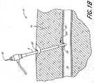
- FIGS 1A-1Billustrate the suturing device 520 in accordance with a preferred embodiment of the present invention in,an exemplary use environment.
- the suturing device 520is used to seal a blood vessel 16 following an interventional catheterization procedure, such as an angiogram.
- an interventional catheterization proceduresuch as an angiogram.
- the physicianmakes an initial incision 20 in the upper thigh 12 of a patient 2.
- the physicianthen inserts a needle (not shown) into the incision 20.
- the physicianknows the needle has pierced the femoral artery 16 through a blood vessel incision 26.
- the physicianthen inserts a guidewire (not shown) through the needle and into the artery 16.
- the physicianmay take the needle out and insert a plastic needle (not shown) over the guidewire once the guidewire is in place.
- the guidewiremay then be taken out.
- a catheter sheath introduceralso called an introducer sheath.
- This introducer sheath 6is typically a single lumen catheter with a valve on its proximal end. The valve is used to prevent extraneous bleed back or to introduce medication into the patient's body.
- the vessel incision 26provides access for medical instruments and probes to be inserted inside the arterial vessel 16. Instruments may be inserted into the artery 16 via the introducer sheath 6 to perform various medical procedures. For example, a catheter may be inserted through the CSI 6 and directed along an arterial path to a target area, such as the heart, to perform one or more percutaneous approach procedures, such as an angioplasty or angiogram.
- the physicianinserts a distal portion of the suturing device 520 into the biological tissue 14 through the CSI 6, as shown in Figures 1A-1B .
- the distal portion of the suturing device 520passes through the CSI 6 and through the vessel incision 26 into the femoral artery 16.
- the device 520is then used to place a suture through the wall 22 of the blood vessel 16 on either side of the vessel incision 26. so that the incision 26 can be efficiently and reliably sealed.
- the distal portionincludes retractable arms 524 (seen in Figure 2 ) which releasably hold the suture within the blood vessel 16.
- a set of flexible, retractable needles 546( Figure 2 ) are used to pierce the blood vessel 16 on opposite sides of the incision 26, capture the ends of the suture from the arms, and withdraw the ends of the suture from the blood vessel 16.
- the arms and the needlescan be remotely deployed and retracted by the physician as needed using a control handle, several embodiments of which are described below.
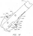
- FIG. 2is a cross-sectional view of a preferred embodiment of the suturing device 520 of Figure 1A with the distal portion inserted through a blood vessel wall 22 via the incision 26.
- the suturing device 520comprises a suture introducer head 522, an elongated body 514, an actuating rod 50, an actuating rod lumen 530, a suture clasp member 500, a pivot pin 502, a pair of suture clasp arm apertures 508, a pair of flexible needles 546, a suture catch 38 on each needle 546, a pair of needle ports or apertures 510, a pair of needle insertion guides 512, a pair of needle housings or needle lumen 516, a suture 40, and an aperture 540 at the distal end of suture introducer head 522.
- the suture clasp member 500comprises a pair of suture clasp arms 524, a pair of protrusions (suture clasp member stopper) 528, a hinge portion of the suture clasp member 542 and a pair of suture clasps 544.
- the deviceis illustrated in Figure 2 following insertion into blood vessel 16, but before deployment of the suture clasp arms 524.
- the CSI 6is withdrawn from the blood vessel 16 to expose the needle ports 510 following insertion of the device, but remains inserted within the thigh.
- the device 520may alternatively be constructed using a unitary body or housing 515, rather than using a separate suture introducer head 522.
- the dimensions of the suturing device 520may vary according to the suture site and the biological tissue intended to be sutured.
- the diameter of the suture head introducer 522is about 0.27 cm (0.105 inches) and the diameter of the hollow elongated body 514 is about 0.25 cm (0.098 inches).
- each needle port 510corresponds to a respective suture clasp arm 524.
- Each needle port 510includes a needle guiding portion 512 ("needle guide”), in the form of an outwardly curved groove or channel, which guides the corresponding needle 546 along a particular path.
- the needle guides 512may be formed within the suture introducer head 522 (as shown in Figure 2 ) as part of a mold, or may be separate pieces (not shown) that are inserted into the suture introducer head 522 during manufacture.
- the needle guidescause the needles 546 to bend outward so that they pierce the blood vessel on either side of the incision 26, and then engage the deployed suture clasp arms 524 to capture respective loops in the ends of the suture 40. Thereafter, the needles 546 are retracted to withdraw the ends of the suture 40 through the incisions 248 created by the needles.
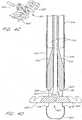
- Figure 7shows a preferred configuration of the hollow elongated body 514 with five lumens.
- Two of the lumens 516are used to house the needles 546 ( Figure 2 ).
- Another lumen 530is used to house the actuating rod 50.
- Another lumen 532is used to hold the length of the suture 40 to prevent the suture 40 from becoming tangled.
- the suture 40may be stored in the actuating rod lumen or in a hole drilled into the suture clasp arm 500.
- the fifth lumen 534is preferably used for 'bleed back,' which lets the physician determine whether the distal end 504 of the suture introducer head 522 is still positioned in the artery 16 after the physician partially removes the CSI 6.
- Bleed backis accomplished by the hole 540 ( Figure 5 ) at the distal end 504 of the suture introducer head 522, the suture clasp arm apertures 508 and any other openings in the suture introducer head 522.
- the direction of blood flow for bleed backis shown by the dashed arrows in Figures 2 and 9 .
- the bleed back lumen 534extends to a port (not shown) at a proximal portion of the device, and the physician can observe the blood pressure through bleed back lumen 534 by monitoring blood flow from the port.
- the bleed back lumenmay be attached to a balloon which inflates when the distal portion 504 of the suture introducer head 522 is within the blood vessel 16.
- a pressure sensoris associated with the blood flow lumen 534 to provide the physician with a numeric reading.
- the fifth lumen 534may be used to inject medication or for diagnostic purposes.
- the suture 40preferably closes the artery vessel opening 26 transverse to the flow of blood. This is the most efficient direction to close the opening 26.
- the exterior surface of the elongated body 514includes a marker 539 which denotes the proximal position to which the CSI 6 should be partially withdrawn (after the distal portion of the suturing device 520 has been inserted into the blood vessel 16) to expose the needle apertures 510.
- the partial withdrawal of the CSI 6is described below.
- the marker 539is shown as a visual marker, but may additionally or alternatively be in the form of a ridge, groove, or other physical structure which interacts with a corresponding structure of the CSI 6 to allow the physician to position the CSI 6 using the sense of feel.
- the CSI 6 and elongated body 514could be configured to releasably engage or interlock with one another when the CSI 6 reaches the proper position along the body 514.
- a specially formed CSI 6 which includes such an interlocking structureis included within the scope of the invention.
- One or more additional longitudinal markerscould be provided along the body 514, distal to the marker 539, to indicate other relative positions of the CSI 6 and the body 514, such as the position at which the retractable arms 524 are exposed outside the CSI 6.
- the suturing device 520includes a single, resilient suture clasp member 500 attached to the actuating rod 50.
- This resilient suture clasp member 500is preferably of a unitary construction as shown.
- the suture clasp member 500comprises a center or hinge portion 542 and two suture clasp arms 524 (one for each needle 546). Each suture clasp arm 524 has a suture clasp 544 at the end thereof.
- the hinge portion 542 of the suture clasp member 500acts as a "living hinge” because it has a memory which causes the member 500 to return to a partially open, unretracted position ( Figure 3 ) when a force (applied via rod 50) is released.
- Figure 3the suture clasp member 500 is deployed in the artery 16 in its predisposed (relaxed or natural) position.
- the suture clasp member 500is retracted into the suture introducer head 522 in its compressed (stressed or tensed) position.
- the arms 524are moved to the retracted position by applying a distal force to the actuator rod 50, which causes the arms to contact deflection surfaces 518 ( Figure 3 ).
- This suture clasp member 500is preferably composed of a resilient shape memory material such as NITINOL.
- the suture clasp member 500may alternatively be composed of another material with spring-like characteristics, such as plastic, spring steel, stainless steel or any variations thereof. Further, the suture clasp member 500 could be composed of two arms that are hingedly connected to the actuating rod 50 without the use of a resilient hinge, as shown in Figures 4C and 4D and described below.
- the living hinge configurationis easily adaptable to having three arms spaced at 120 degrees or four arms (as in Figures 19 and 20 ) spaced at ninety degrees. If there are three arms, then there are preferably 3 needles 546 and six lumens in the elongated body 514. Thus, other configurations and numbers of arms can be incorporated into the device to accomplish the specific needs of the application.
- the needles 546are flexible and preferably made from a material with shape memory, such as SUPERFLEX NITENOL Alternatively, the needles 546 may be composed of spring steel, surgical stainless steel or any variation thereof.
- the diameter of the needles 546is preferably about 0,05 cm (0.019 inches), but needles with other diameters may be used in accordance with the present invention.
- the needle insertion guides 512cause the needles 546 to bend radially outward.
- the needles 546also preferably further bend slightly (radially outward) when they come in contact with the angled surfaces 545 of the suture clasp arms 524, as shown in Figure 8 .
- the needles 546are retracted into the needle lumens 516, they resume a straight configuration as a result of their resiliency.
- the embodiment of Figures 2-9preferably uses flexible needles which bend during deployment, it is contemplated that non-bending needles, which may be either straight or curved, could alternatively be used.
- the actuating rod 50attaches to the resilient suture clasp member 500 by, a pivot pin 502.
- the actuating rod 50 in this configurationpreferably comprises a single shaft (as shown), but may comprise a plurality of shafts in other configurations.
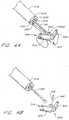
- Figure 4Cis a perspective view of a non-living hinge embodiment or a two-piece suture clasp member 501.
- Figure 4Dis a cross-sectional view of the two-piece suture clasp member 501 and a ramp or spreader 523 within the suture introducer head 522.
- the hinge portion of the suture clasp member 501is similar to a hinge portion shown in Figure 14 , which is described below.
- the spreader 523may be a separate piece attached within the suture introducer head 522.
- the spreader and suture introducer head 522may comprise a single molded piece.
- the length of the suture clasp arm 525is preferably about 0.54 cm (0.174 inches).
- the length of both of the suture clasp arms 525, 525' together in their fully extended position (deployed with both arms parallel to each other)is preferably about 0.73 cm (0.288 inches). In other configurations of the suture clasp arms 525, 525', the dimensions may vary.
- the actuating rod 50is advanced distally, and the interior edges 518 of introducer head 522 come in contact with the suture clasp arms 525, 525.' The interior edges 518 of introducer head 522 cause the two suture clasp arms 525, 525' to retract radially inward relative to the actuating rod 50.
- the general use and operation of the two-piece suture clasp member 501is similar to the use and operation of the one-piece suture clasp member 500 shown in Figure 4A , as described below.
- the proximal portion of the suturing device 520preferably includes a handle which allows the physician to externally operate the suture clasp arms 524 and the needles 546 inside the blood vessel 16.
- This handlepreferably has three actions: a first action in which the actuating rod 50 applies a proximal force to the hinge portion 542 to deploy and maintain the arms 524 in a fully outward position ( Figure 8 ); a second action to advance the needles 546 distally ( Figure 8 ) and pull the needles 546 back proximally using one or more springs; and a third action in which the actuating rod 50 applies a distal force to the hinge portion 542 to retract the arms 524 ( Figures 2 , 4D or 9 ).
- the handlemay be a 2-action handle in which one of the two actions is a combination of two of the three actions described above for the 3-action handle.
- the actuating rod 50applies a proximal force to the hinge portion 542 to deploy and maintain the suture clasp arms 524 in a fully extended state of Figure 8 .
- the needles 546automatically advance distally ( Figure 8 ) and retract proximally to capture the looped ends of the suture 40.
- the actuating rod 50applies a distal force to the hinge portion 542 to retract the suture clasp arms 524 ( Figures 2 , 4D or 9 ).
- This 2-action handleis suited for physicians with more experience in operating this suture device 520. It will be apparent to one of ordinary skill in the art that a 1-action handle or a 4-action handle (inserting and withdrawing the needles 546 as two separate actions) could be used, or that separate handles or triggers could be provided for different actions. Several different handle designs are described below.
- Figure 10is a cross-sectional view of a handle 550 according to one embodiment of the invention.
- the handleis operatively attached to the proximal end of the hollow elongated body (shown in dashed lines), and may be used with any of the embodiments of the device disclosed herein.
- Figure 11is a cross-sectional, cut-away perspective view of the handle 550 of Figure 10 .
- Figure 18is a perspective view of an entire device 520 which includes the handle 550 of Figure 10 .
- the handle 550comprises an actuating rod aperture 551, a main housing 552, a pair of finger grips 554, a suture clasp arm piston 556 with a locking groove 576, a needle piston 560 with at least one raised key portion 562, a releasor 568 with a locking stopper 572, a pivot pin 570, a releasor support 574, a compression spring (not shown) operatively positioned in a spring recess 578 between the suture clasp arm piston 556 and the needle piston 560, a needle piston support cylinder 580 with at least one grooved recess 564 and needle clamps 584.
- the housing 552is attached to or is a continuation of the hollow elongated body 514 of Figure 2 or the single suture insertion and retraction housing 515 of Figure 9 or the suturing device of Figure 13A .
- the housing 552is separate from the hollow elongated body 514 ( Figure 2 ) or the single suture insertion and retraction housing 515 ( Figure 9 ) or the device of Figure 13A .
- the actuating rod 50connects the housing 552 with the hollow elongated body 514 ( Figure 2 ) or the single suture insertion and retraction housing 515 ( Figure 9 ) or the device of Figure 13A .
- a proximal portion of the actuating rod 50slides through the actuating rod aperture 551 at the distal end of the housing 552.
- the proximal end of the actuating rod 50is attached to the distal end 558 of the suture clasp arm piston 556, which is slidably received within the main housing 552.
- a compression spring(not shown) resides in the spring recess 578 of the housing 552 between the suture clasp arm piston 556 and the needle piston 560 and simultaneously exerts two forces: a distal force on the suture clasp arm piston 556; and a proximal force on the needle piston 560.
- the needle clamps 584 of the needle piston 560hold the proximal ends of the needles 546.
- the needle piston 560is slidably received within a distal portion of the housing 552.
- the needle piston support cylinder 580is attached to the housing 552 and preferably does not move relative to the housing 552.
- the releasor 568pivots radially inward and outward on the pivot pin 570.
- the releasor support 574exerts a radially outward force on the releasor 568. This force causes the releasor 568 to pivot and the locking stopper 572 to fall into the locking groove 576 of the suture clasp arm piston 556 when the locking groove 576 is aligned to receive the locking stopper 572.
- the releasor support 574is preferably made of a resilient shape memory material such as NITINOL
- the releasor support 574may alternatively be composed of another material with spring-like characteristics, such as plastic, spring steel, stainless steel or variations thereof. Other embodiments of the handle are described below with reference to Figures 12 , 21 and 22 .
- the physicianinserts the distal portion of the device through a CSI 6 and into the artery 16 ( Figures 1A-1B ), such that the needle ports remain outside the artery 510.
- the CSI 6is then partially withdrawn proximally along the elongated body 514 of the suturing device 520 to remove the CSI 6 from the artery 16 and expose the needle apertures 510, as shown in Figure 2 .
- the distance of the partial removal of the CSI 6(proximal relative to the elongated body 514) is substantially less than the length of the elongated body 514 within the flesh 14.
- the ability to insert and withdraw the device 520 through the CSI 6has the important advantage of reducing disturbance or damage to the surrounding flesh 14 of the patient's thigh 12 and the vessel incision 26.
- the distal end 504 of the introducer head 522has a smooth, rounded surface to prevent injury to the opposite vessel wall 506 when inserting the introducer head 522.
- the blood flow in the artery 16is uninterrupted because the introducer head 522 does not occlude the artery 16.
- the physicianmay use the aperture 540 at the distal end of the suture introducer head 522 and the bleed back lumen 534 to determine when the distal end 504 of the suture introducer head 522 is in the artery 16.
- the actuating rod 50holds the resilient suture clasp member 500 in its compressed position within the introducer head 522.
- the actuating rod 50applies a downward force while the interior edges 518 of the introducer head 522 apply an inward force on the two suture clasp arms 524.
- the combination of these two forcescause the hinge portion 542 of suture clasp member 500 between the two arms 524 to elastically deform or compress.
- the suture clasps 544hold the looped ends of a suture 40 in the angled slot of the suture clasps 544 as shown in Figures 2 and 4A .
- the looped ends of the suture 40are held securely by the suture clasps but are positioned for easy removal by the suture catches 38 of the needles 546.
- the physicianmay deploy the suture clasp arms 524 ( Figure 3 ) by pulling the finger grips 554 in a proximal direction relative to the housing 552 ( Figure 11 ).
- a physicianmay pull the suture clasp arm piston 556 proximally by placing the physician's index and middle finger around the finger grips 554 and pushing on the proximal end 582 of the housing 552. This action is similar to operating a standard syringe. This motion compresses the spring (not shown) in the spring recess 578 of the handle 550 in a proximal direction.
- the actuating rod 50moves in a proximal direction relative to the elongated body 514 or housing 515. This is shown by the arrows in Figure 3 .
- This motioncauses the suture clasp member 500 to deploy or open to its predisposed or natural position as shown in Figure 3 .
- the suture clasp arms 524deploy out of the introducer head 522 into the blood vessel 16 through two suture clasp arm apertures 508 ( Figure 3 ), one on either side of the introducer head 522.
- the locking stopper 572 at the distal end of the releasor 568moves radially inward and falls into the locking groove 576 of the piston 556.
- the locking stopper 572in combination with the locking groove 576, prevents the suture clasp arm piston 556 from advancing distally.
- the force of the spring in recess 578prevents the suture clasp arm piston 556 from moving proximally.
- the locking of the suture clasp arm piston 556stabilizes the suture clasp arms 524 in a locked position before the needles 546 are advanced distally.
- the suture clasp arms 524preferably have reached their fully extended position, as shown in Figure 8 .
- the actuating rod 50(attached to the suture clasp arm piston 556) has pulled the resilient suture clasp member 500 up, and the proximal inside edges 536 of the aperture 508 have come in contact with the arms 524 or the suture clasp member 500.
- Figure 8The pulling of the actuating rod 50 and the stationary inside edges 536 of the apertures 508 cause the arms 524 to bend backward until the arms 524 are longitudinally aligned with each other, as shown in Figure 8 .
- the resilient suture clasp member 500is deformed from its natural configuration again, but this time in an extended position instead of a compressed position.
- the physicianmay move the suturing device 520 proximally so that the arms 524 touch the interior of the vessel wall 22 while the needles 546 advance distally and capture the ends of the suture 40 from the suture clasps 544.
- the physiciantwists the needle piston 560 clockwise or counter-clockwise until the raised key portion 562 of the needle piston 560 matches the grooved recess 564 of the needle piston support cylinder 580.
- the grooved recess 564 of the needle piston support cylinder 580allows the raised key portion 562 of the needle piston 560 to advance distally. Otherwise, the needle piston 560 may not be advanced distally if the raised key portion 562 does not match the grooved access 564.
- the needle piston support cylinder 580 and the raised key portion 562 of the needle piston 560prevent the needles 546 from advancing distally prematurely or improperly. Premature or improper insertion of the needles may cause damage to the patient's surrounding tissue 14 ( Figure 1B ) or the blood vessel 16.
- the physicianmay advance the proximal end of the needle piston 560 (with the physician's thumb or palm) in a distal direction relative to the proximal end 582 of the housing 552. This motion compresses the spring in the spring recess 578 in a distal direction.
- the needle piston 560advances distally, the needles 546 and the suture catches 38 on the needles ( Figure 8 ) also advance distally.
- the paths taken by the needles 546are illustrated in Figure 8 .
- the needles 546slide along the needle housings 516 (or needle lumens) and out of the suture device 520 through needle apertures 510.
- the needles 546come in contact with the needle insertion guides 512, the needles 546 begin to bend radially outward.
- the needles 546 exitthey are guided at a radially outward, acute angle away from the actuating rod 50 by the needle insertion guides 512.
- the angle of the needle deflectionis preferably 13.2 degrees. Deflection angles in the ranges of 10 to 15 degrees and 5 to 20 degrees are also contemplated.
- the needles 546then penetrate the vessel wall 22 at an angle and create incisions 248 on either side of the main vessel incision 26.
- the needles 546also preferably bend slightly (radially outward) when they come in contact with the suture clasp arms 524 as the result of contact with angles surfaces ( Figure 8 ) of the suture clasp arms.
- the combination of the suture clasps 544 and the suture catches 38 on the needles 546creates a lock on the looped ends of the suture 40, such that the suture ends will not fall off while the needle 546 engages the suture clasp member 500.
- the physicianadvances the needle piston 560 distally until the resistance of the compression spring prevents the needle piston 560 from advancing any further distally.
- the needles 546are sufficiently advanced in the blood vessel 16 such that when the needles 546 are pulled back proximally, the suture catches 38 on the needles 546 will catch the looped ends of the suture 40 from the suture clasps 544.
- the clasp arms 524hold the suture loops away from the suture introducer head 522, so that the needles 546 pierce the vessel 22 and catch the suture loops outside the perimeter of the suture introducer head 522.
- the physicianadvances the needle piston 560 to its farthest distal position, the physician releases the needle piston 560.
- the compressed springcauses the needle piston 560 to immediately spring back proximally. This motion causes the distal portion of the needles 546 to immediately spring back proximally into the needle housing 516 with the looped ends of the suture 40 attached to the suture catches 38.
- the suture catches 38 on the needles 546catch the suture loops held by the suture clasps 544 and pull the ends of the suture 40 up through the punctured holes 248 when the needles 546 are retracted proximally.
- the needles 546are retracted into the needle lumens 516, they resume a straight configuration.
- the length of the suture 40is released (as a result of the tension caused by the retracting needles 546) from where it resided in the suture lumen 532, through an aperture 540 at the distal end 504 of the suture introducer head 522 and into the artery 16.
- the physicianpresses the proximal portion of the releasor 568 in a radially inward direction. This motion causes the releasor 568 to pivot.
- the locking stopper 572moves radially outward and releases the locking groove 576.
- the force of the compressed springcauses the suture clasp arm piston 556 and the actuating rod 50 to advance distally. Together with the proximal interior edges 518 of the introducer head 522, the downward force of the actuating rod 50 causes the resilient suture clasp member 500 to retract into its compressed position.
- the suture clasp arms 524retract into respective apertures or grooves 508 on the exterior surface of the introducer head 522.
- the arms 524are substantially parallel with the elongated body 514.
- the exterior surfaces of the arms 524are flush with the exterior surface of the introducer head 522. This reduces the likelihood that the arms 524 will catch on the vessel wall 22, flesh 14 or CSI 6 during withdrawal.
- the device 520is now ready for removal from the blood vessel 16.
- the physicianwithdraws the suturing device 520 out of the blood vessel 16 and out of the flesh 14 of the patient's thigh 12 via the CSI 6.
- the physicianpulls the ends of the suture 40 and closes the main vessel incision 26.
- the physicianthen ties at least one knot with the ends of the suture 40 and slides or pushes the knot(s) down through the CSI 6 to the vessel incision 26.
- the physicianmay fasten a small, circular or flat stainless steel clip (not shown) to the ends of the suture 40 and slide the clip down through the CSI 6 to the vessel opening 26 to close the opening 26.
- the physicianthen cuts the unused ends (extra length) of the suture 40 and removes the cut portions.
- the physicianremoves the CSI 6 from the patient's thigh 12.
- the locked position of the suture clasp arms 524provides a stable base or foundation for holding the looped ends of the suture 40 while the needles 546 come in contact with the suture clasp arms 524 and capture the suture 40.
- the suture clasp arms 524are preferably locked in the locked position by the proximal force of the actuating rod 50, the stationary inside edges 536 of the apertures 508, and the protrusions 528 at the 'elbow' end of each arm 524 ( Figure 8 ).
- each arm 524becomes substantially parallel with each other (i.e., each arm 524 is at an angle of approximately 90 degrees from the actuating rod 50)
- the protrusions 528 at the 'elbow' end of each arm 524come into contact with each other and preferably prevent the arms 524 from bending any further than the configuration shown in Figure 8 .
- the protrusions 528preferably prevent the suture clasp member 500 from moving or bending unintentionally (opening any farther) when the needles 546 are inserted distally and come in contact with the suture clasp arms 524. This reduces the risk of the looped ends of the suture 40 being accidently displaced from the suture clasps 544 when the needles 546 engage the suture clasps 544.
- the shape and position of the angled slits of the suture clasps 544 in Figures 2-9provide another advantage.
- the slits of the suture clasps 544 in Figures 2-9are angled in a proximal, radially inward direction.
- the face of the looped ends of the suture 40face in a proximal, radially inward direction.
- This configurationreduces the likelihood that the looped ends of the suture 40 will improperly or prematurely fall off the suture clasps 544.
- the needles 546 engage the suture clasp arms 524preferably the only direction the looped ends may move is in a proximal, radially inward direction, which is in the opposite direction of the inserted needles 546.
- retractable suture clasp armsare used to hold the suture 40 beyond the outer circumference of the tubular housing (and thus beyond the boundaries of the incision 26), and flexible needles 546 are used to capture the held suture 40 outside the outer circumference.
- the suture clasp assemblymay be in the form of a fixed (non-moving) member which holds the suture 40 near or within the circumference of the housing.
- curved needlesmay be used which pierce the vessel wall outside the circumference of the housing and then "curve in” to capture the suture. The curved needles may then be withdrawn to pull the ends of the suture out of the vessel wall 22.
- FIG 12is a cross-sectional view of another embodiment of a handle 600 which may be used in place of the handle of Figure 10 .
- the handle 600 of Figure 12comprises a housing 602 with a spring recess 622, a pair of external finger grips 604 (only one shown in Figure 12 ), a suture clasp arm piston 606 with a locking groove 608, a releasor 612 with a locking head 610 and a needle piston stopper 618, a pivot pin 614, a needle piston 620 with needle clamps 616 and a spring 624.
- the handle 600also includes a second spring (not shown) which biases the releasor 612 toward a position in which the locking head 610 is engaged with the groove 608. Similar to the handle 550 shown in Figures 10 and 11 , the finger grips 604 extend outside the housing 602 to allow a physician to move the piston 606 relative to the housing 602. The proximal ends of the needles 546 in Figure 12 are attached to the needle clamps 616, which are attached to the needle piston 620. The actuating rod 50 ( Figure 2 ) is attached to the suture clasp arm piston 606 in Figure 12 .
- the general operation of the handle 600 shown in Figure 12is similar to the operation of the handle 550 shown in Figures 10-11 .
- the needle piston stopper 618prevents the needle piston 620 from distally advancing prematurely or improperly. This function is similar to the function of the raised key potion 562 and grooved recess 564 of the handle 550 shown in Figures 10-11 .
- the physicianadvances the suture clasp arm piston 606 proximally against the biasing force of the spring 614 (by pulling the finger grips 604 proximally) to deploy the suture clasp arms 524 ( Figure 3 ) until the locking head 610 of the releasor 612 moves radially inward and falls into the locking groove 608.
- the clasp arms 524are in the fully deployed or open position as in Figure 8 .
- This motioncauses the proximal portion of the releasor 612 to advance radially outward until the needle piston stopper 618 is no longer blocking the needle piston 620.
- the physicianmay advance the needle piston 620 distally into the recess 622 to cause the needles 546 to advance distally and capture the suture 40.
- the spring 614moves the needle piston proximally to the outward position, causing the needles 546 to retract with the suture 40.
- the physicianpresses the external lever portion of the releasor 612 to release the suture clasp arm piston 606; this causes the suture clasp arms 524 to return to the retracted position, so that the device 520 can be withdrawn from the artery 16.
- this handleattached to the proximal end of the device 520.
- there are at least two springs or sets of springs(not shown), instead of the single compression spring as used by the handle 550 in Figures 10-11 and the handle 600 in Figure 12 .
- a first springexerts a proximal force on the needles 546 while a second spring exerts a distal force on the actuating rod 50 inside the handle.
- the physicianmanually retracts the needles 546 proximally back into the needle housing 516.
- Figures 13A-17illustrate the device of Figure 1A according to another embodiment of the invention.
- the ends of the suture 40are provided with special loops or fittings 41 that are configured to engage with the needles 650 ( Figure 16 ).
- a first suture clasp arm 630comprises a hinge portion 636 with an aperture 642 for a pivot pin 502 ( Figure 4C ).
- the first suture clasp arm 630further comprises a curved portion 638 for the distal end of an actuating rod 50 (as in Figure 4B ) and the hinge portion of a second suture clasp arm 630' ( Figure 14B ).
- the first suture clasp arm 630further comprises an annular recess 632 for holding a suture looped end 41, a slit 640 for the length of the suture 40, and a sloped end 634.
- Figure 14Billustrates the second suture clasp arm 630', which is the other half of a two-piece suture clasp member.
- the second suture clasp arm 630'is similar to first suture clasp arm 630 except the second suture clasp arm 630' does not have a curved portion 638 for the distal end of an actuating rod 50 ( Figure 4B ).
- the length of the first suture clasp arm 630is preferably about 0.54 cm (0.174 inches).
- the length of both of the suture clasp arms 630, 630' together in their fully extended position (deployed with both arms parallel to each other)is preferably about 0.73 cm (0.288 inches). In other configurations of the suture clasp arms 630, 630', the dimensions may vary.
- each of the flexible needles 650comprises an extended shaft, a penetrating distal tip 654, and a groove 652 near the distal end.
- the needle groove 652acts as a detent mechanism or suture catch.
- the grooves 652extend around the complete circumference of the needles 650.
- the grooves 652are partially circumferential along the radial edge of the needles 650.
- the loops 41correspond generally in diameter to grooves 652 of the needles 650, but are sufficiently resilient to expand in diameter in response to the downward force of the needles 650.
- the looped end 41 of the suture 40may be formed by heating one end of a length of suture until the end becomes a ball-shaped configuration. The ball-shaped end is then compressed into a disc shape. A hole is then made near the center of the disc-shaped end such that the disc-shaped end forms a loop.
- the suture 40comprises a monofilament or plastic suture material, such as prolene or declene.
- the suture endinstead of heating the end of a suture length, the suture end is simply compressed and a hole is formed thereafter. The end may be further cut or stamped into a circle shape.
- the actuation of the needles 650is used to form the hole and fasten the ends of the suture to the needles 650.
- a separately-formed loopis insert-molded, glued, crimped or otherwise attached to the end of a length of suture.
- Each loop 41may have circular configuration as shown in Figure 13A , or may have another appropriate configuration such as an oval, triangle, rectangle, hexagon, or octagon.
- FIG. 13A-17The general use and operation of the device of Figures 13A-17 is substantially the same as described above with reference to Figures 2-9 .
- the looped ends 41 of the suture 40are placed within the annular recess 632 of the suture clasp arms 630, 630' ( Figures 13A and 15 ).
- the suture introducer head 522is inserted into biological tissue 14 (similar to Figures 1A-2 ), and the suture clasp arms 630, 630' are deployed radially outward ( Figure 16 ).
- the penetrating flexible needles 650pass through the biological tissue to be sutured (similar to Figure 8 ) and engage the suture clasp arms 630, 630' ( Figure 17 ).
- the looped ends 41flex radially outward momentarily.
- the looped ends 41come in contact with the grooves 652.
- the looped endsflex radially inward and fasten around the needle grooves 652, such that pulling the needles 650 proximally causes the suture ends 41 to follow the proximal movement of the needles 650.
- the grooves 652serve the same general purpose as the suture catches 38 ( Figure 2 ) described above with reference to Figures 2-3 and 8 .
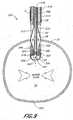
- FIGs 19-20are perspective views of a four-arm suture clasp assembly which may be used with a device similar to the suturing device 520 of Figure 1A-2 .
- the suture clasp assemblyincludes four suture clasp arms 662-668, each of which corresponds to a respective needle (not shown) and needle port (not shown) of the device.
- Each of the four suture clasp arms 662-668comprises an annular recess and a slit for the length of the sutures.
- two suturesare used with the device shown in Figures 19-20 , each of which is held by a pair of suture clasp arms 662-668.
- Each suturehas a loop at either end which is placed within one of annular recesses of a suture clasp arm 662-668.
- the arms 662-668may alternatively be provided with one of the other types of suture clasp structures disclosed above.
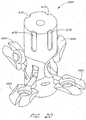
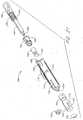
- FIGS 21 and 22illustrate a handle 700 according to another embodiment of the invention.
- the handle 700comprises a thumb ring 702, a plunger 704, a plunger distal end 706, a main housing 710, a proximal aperture 708, a finger ring 712, a sloped floater peg slot 714, a floater clamp slot 715, a distal end aperture 716, a floater 720, a peg 718, a floater clamp lock 722, a floater clamp 724, a drive wire (actuating rod 50) clamp 726, a needle holder backer 728, a needle holder 730, a floater clamp peg 732, a floater clamp aperture 734, a spring 736, a plunger pegs 738, L-shaped lock recess 740 and an extrusion (hollow elongated body 514) clamp 742.
- the spring 736, the floater 720, the floater clamp lock 722, the floater clamp 724, the drive wire clamp 726, the needle holder backer 728, the needle holder 730 and the extrusion clamp 732are operatively received within the main housing 710.
- the shaft of the plunger 704is slidably received through the floater-720, the floater clamp lock 722 and the floater clamp 724.
- the square- or rectangular-shaped shaft of the plunger 704fits within the square- or rectangular-shaped axial recess of the floater 720, such that rotating the plunger 702 clockwise causes the floater 720 to rotate clockwise as well.
- the plunger .distal end 706is adapted to snap into or otherwise attach itself into the needle holder backer 728.
- the plunger pegs 738are slidably received along the L-shaped lock recess 740 formed on the interior of the main housing 710.
- the L-shaped recess lock 740, the floater peg slot 714 and the floater clamp slot 715are all molded, carved or otherwise formed on the interior of the main housing 710.
- the spring 736provides a proximal biasing force on the plunger pegs 738 and the plunger 704.
- the spring 736also provides a distal biasing force on the floater 720.
- the floater peg 718is slidably received along the sloping floater peg slot 714.
- the distal end of the floater 720snaps and locks into the proximal portion of the floater clamp lock 722.
- the floater clamp lock 722is preferably glued, bonded or otherwise attached to the floater clamp 724.
- the drive wire clamp 726fits within the aperture 734 of the floater clamp 724.
- the drive wire clamp 726is glued, bonded or otherwise attached to a proximal portion of a drive wire or the actuating rod 50 of Figures 13B (or Figures 2 or 9 ).
- the extrusion (hollow elongated body 514) clamp 742is glued, bonded or otherwise attached to a proximal portion of the hollow elongated body 514 of Figure 13A .
- the needle holder 730is preferably glued, bonded or otherwise attached to the needle holder backer 728.
- the proximal portion of the needles 546 of Figure 2 or the needles 650 of Figure 16are preferably glued, bonded, molded into or otherwise attached to the needle holder 730.
- the plunger pegs 738 within the L-shaped lock recess 740prevent the plunger 704 from moving distally relative to the main housing 710.
- the plunger pegs 738move circumferentially along the L-shaped lock recess until the plunger pegs 738 are positioned to slide distally down the longitudinal part of the L-shaped lock recess 740.
- the floater 720As the physician rotates the plunger 704, the floater 720 also rotates clockwise. The peg 718 moving within the sloped floater peg slot 714 causes the floater 720 to move proximally. Because the drive wire clamp 726 is attached to the drive wire or actuating rod 50 ( Figure 13A ), the proximal movement of the floater 720 causes the floater clamp lock 722, the floater clamp 724, the drive wire clamp 726, and the actuating rod 50 to move proximally, such that the suture clasp arms 630, 630' deploy radially outward ( Figures 13A-13B ).
- the physicianmay advance the plunger 702 distally.
- the distal movement of the plunger 702causes the needles 546 ( Figure 8 ) or the needles 650 ( Figure 16 ) to advance distally, penetrate the biological tissue, and engage the suture clasp arms 524, 630, 630' ( Figure 8 and Figure 16 ).
Landscapes
- Health & Medical Sciences (AREA)
- Life Sciences & Earth Sciences (AREA)
- Surgery (AREA)
- Molecular Biology (AREA)
- Engineering & Computer Science (AREA)
- Biomedical Technology (AREA)
- Heart & Thoracic Surgery (AREA)
- Medical Informatics (AREA)
- Nuclear Medicine, Radiotherapy & Molecular Imaging (AREA)
- Animal Behavior & Ethology (AREA)
- General Health & Medical Sciences (AREA)
- Public Health (AREA)
- Veterinary Medicine (AREA)
- Cardiology (AREA)
- Surgical Instruments (AREA)
- Prostheses (AREA)
Abstract
Description
- The present invention relates to medical suturing devices. More particularly, the present invention relates to suturing devices for closing an opening in an arterial or other biological tissue wall that is not directly accessible to the physician.
- Physicians frequently use sutures to close cuts, punctures, incisions and other openings in various biological tissue, such as blood vessels, of the human body.
- In an arterial catheterization procedure, a relatively small percutaneous incision is made in the femoral or other artery. A catheter is inserted through the incision and directed along an arterial path to a target area, such as the heart, to perform one or more procedures, such as an angioplasty or angiogram. These procedures are designed to be relatively quick 'outpatient' procedures.
- Upon completion of the catheterization procedure, the physician typically creates a 'thrombus patch' by applying direct pressure to the patient's thigh to make the blood around the incision clot. Because the femoral artery must not be completely blocked (occluded) by the applied pressure, the physician commonly applies direct pressure by hand for the first twenty minutes after the procedure. During this time, the physician can feel the pulse to assure the artery is not occluded. Afterwards, the physician usually turns the procedure over to an assistant who applies direct pressure using sandbags, clamps or other devices. A significant problem with this approach is that it is frequently necessary to apply the pressure for an extended period of time, such as twenty-four hours or longer.
- Another problem with the thrombus patch method is that the high blood pressure in the artery can cause the thrombus patch to rupture or burst while direct pressure is being applied to the thigh or after direct pressure is removed. This requires the whole process to be restarted. If the patch ruptures and is not restored, the patient may bleed to death. Because thrombus patches frequently burst, the patient frequently must remain in the hospital or catheterization lab overnight for observation. Thus, these 'out-patient' procedures become 'in-patient' procedures, simply because a thrombus patch it is difficult to create. Staying in the hospital increases patient discomfort and hospital expenses, which are often disproportionate to the actual medical procedure performed.
- Furthermore, if a thrombus patch cannot be formed, the physician may need to anesthetize the patient, occlude blood flow to the artery, make a large incision in the thigh to allow conventional suturing with a needle, suture the artery with conventional means, restore blood flow to the artery, and suture the incision in the thigh. This results in additional discomfort and expenses for the patient.
- While the above problems could potentially be avoided by suturing the blood vessel immediately following the catheterization procedure, the size and location of the artery make suturing difficult. Specifically, the opening in the thigh is typically too small and too deep to provide enough working space for suturing the artery using conventional methods. Thus, in order to suture the vessel according to conventional methods, the opening in the thigh would have to be significantly enlarged, potentially exposing the patient to additional pain, scarring, and health risks.
International Patent Application WO 97/07745 US patent 5,417,699 relates to a suture applying device comprising a shaft which carries a pair of needles near its distal end. The needles are joined by a length of suture, and the shaft is used to both introduce the needles into a lumen of a body structure and to push the needles back through tissue on either side of the puncture site. After the needles have passed through the tissue, they are captured on the shaft and drawn outward through the tract, leaving a loop of suture behind to close the puncture site near the body lumen. The suture can then be tied and the knot pushed back through the tract to complete the closure. Alternatively, a locking fastener formed of a resorbable material can be placed into the penetration over the sutures and the sutures tied over the fastener.- The present invention addresses the above problems by providing a suturing device for suturing an opening in a biological tissue well, such as an organ or blood vessel. The device is particularly well suited to suture an opening made in an artery, such as the femoral artery, following a catheterization procedure. The device eliminates the need to apply pressure to a patient's thigh for an extended period of time, and eliminates many of the complications and costs associated with the creation of a thrombus patch.
- In a preferred embodiment, the device comprises an elongated tubular body having a distal portion which is adapted to be inserted percutaneously through an initial incision and into the blood vessel. The distal portion has a pair of retractable arms which can extend from the distal portion of the elongated body and releasably hold a suture within the blood vessel. The arms retract into and extend out from respective openings on sides of the elongated tubular body.
- First and second retractable needles, each of which is configured to catch the suture or a looped end of the suture from a respective retractable arm, are provided along the elongated body proximal to the retractable arms. The arms and the needles are remotely movable by the physician using a handle or other control mechanism provided at a distal portion of the device. The needles extend distally and outwardly from the elongated body (preferably by flexing outward during deployment) to capture the suture.
- In operation, following a catheterization procedure in which a standard catheter sheath introducer (CSI) is used to introduce a catheter into a blood vessel, the distal portion of the elongated body is introduced into the blood vessel through the CSI. The CSI may advantageously be left substantially in the inserted position during the suturing procedure. During insertion, the retractable arms are maintained in their retracted position. Once inside the blood vessel, the arms are deployed to hold the ends of the suture beyond the circumference of the elongated tubular body. Using a control handle, the needles are then deployed from and then retracted into the elongated body, during which time the needles pierce the vessel wall on substantially opposite sides of the incision, release and capture the suture ends from the retractable arms, and pull the ends of the suture through the vessel wall. The arms are then moved to their retracted position, and the device is withdrawn from the blood vessel and the patient's body with the ends of the suture. A knot or suture clip may then be advanced to the incision site to close the incision.
- In accordance with the invention, there is provided a suturing device for remotely suturing biological tissue, comprising: a body portion; introducing means moveably mounted to the body portion for movement between a retracted position and an extended position and for removably holding a portion of a suture such that the suturre portion is held away from the body when the introducing means is in its extended position; at least one needle movably mounted, relative to the introducing means, between a retracted position and an extended position for penetrating the biological tissue and capturing said suture portion; and at least one needle insertion guide, characterised in that the or each needle insertion guide is arranged to cause an associated needle to bend outwardly from said body portion as the associated needle is deployed to the extended position so as to penetrate the biological tissue.
- The distal section of the elongated body, including the needles and the needle ports, is preferably configured to be percutaneously introduced into a patient through a standard CSI used to perform a catheterization procedure, such that the needles may be extended and retracted to capture and withdraw the suture without removing the CSI from the patient. A proximal section of the elongated body preferably includes a marker on an outer surface, the marker indicating a longitudinal position to which the CSI may be partially withdrawn to expose the needle ports.
- The needles have a substantially straight configuration when in the retracted position. The needle ports include needle guides which apply an outward force to the needles to cause the needles to bend outward. In one embodiment, each needle includes a notch formed therein for capturing a loop in the suture. In another embodiment, each needle includes groove formed circumferentially therein, the groove being configured to engage a loop or fitting at an end of the suture.
- The first and second arms are preferably interconnected by a flexible, resilient hinge which holds the arms in a partially open position when the hinge is in a relaxed state. The flexible hinge is preferably coupled to an actuator shaft which extends within a lumen of the body, such that application of a proximal force to the actuator shaft causes the arms to move from the partially open position to the deployed position, and such that application of a distal force to the actuator shaft causes the arms to move from the partially open position to a retracted position. The outer surfaces of the first and second arms are preferably flush with an outer surface of the body, and the arms substantially parallel to the body, when the arms are retracted within the body. The first and second arms preferably extend radially outward from the body at an angle of approximately 90 degrees when in the deployed position. The arms are preferably spaced proximally from a distal tip of the body, so that the arms are inhibited from contacting a wall of the blood vessel opposite the incision during deployment.
- The distal portion of the body preferably includes at least one blood port which is fluidly coupled to a lumen within the elongated body. The lumen extends to a proximal portion of the elongated body to allow a physician to determine whether the distal portion is in the blood vessel. The lumen may be coupled to a pressure sensor that provides a visual indication of whether the distal portion is in the blood vessel.
Figure 1A illustrates a distal section of a suturing device in accordance with the present invention in an exemplary use environment, with the device shown on cut-away form.Figure 1B is a cross-sectional view of the device ofFigure 1A .Figure 2 is a cross-sectional view which illustrates the construction of the device ofFigure 1A in accordance with one embodiment of the invention, wherein the distal end of the device is shown inserted through a blood vessel wall.Figure 3 is a cross-sectional view of the device ofFigure 2 with the suture clasp member partially deployed.Figure 4A is a perspective, cut-away view of the device ofFigure 2 , showing a suture clasp member, an actuator and a hollow elongated body.Figure 4B is an exploded view of the suture clasp member, pivot pin and actuator ofFigure 4A .Figure 4C is a perspective view of a two-piece suture clasp member according to another embodiment of the invention.Figure 4D is a cross-sectional view of the two-piece suture clasp member ofFigure 4C and a spreader within a suture introducer head.Figure 5 is a perspective view of the suture introducer head and suture clasp member ofFigure 2 .Figure 6 is perspective view of the device ofFigure 2 with the suture clasp member partially deployed and holding a suture.Figure 7 is a perspective cut-away view of the device ofFigure 2 .Figure 8 is cross-sectional view of the device ofFigure 2 with the suture clasp arms fully deployed and holding a suture within a blood vessel.Figure 9 is a cross-sectional view of another embodiment of theFigure 1A device.Figure 10 is a cross-sectional view of a handle of the, device ofFigure 1A according to one embodiment of the invention.Figure 11 is a perspective view of the handle ofFigure 10 .Figure 12 is a cross-sectional view of a handle according to another embodiment of the invention.Figure 13A is a perspective view which illustrates another embodiment of theFigure 1A device.Figure 13B is a cross-sectional view of the device ofFigure 13A .Figure 14A-14B are perspective views of a two-piece configuration of the suture clasp member ofFigure 13A .Figure 15 is a perspective view of the device ofFigure 13A with the suture clasp arms partially deployed.Figure 16 is a perspective view of the device ofFigure 13A with the suture clasp arms fully deployed.Figure 17 is a perspective view of the device ofFigure 13A with the suture clasp arms fully deployed and needles engaging the suture clasp member.Figure 18 is a perspective view of theFigure 1A device with the handle ofFigure 10 .Figures 19-20 are perspective views of a four-arm suture clasp assembly according to another embodiment of the invention.Figure 21 is an exploded view of a handle according to another embodiment of the invention.Figure 22 is a perspective view of the handle ofFigure 21 .- The present invention provides a suturing device for suturing biological tissue. Various embodiments of the suturing device are described below. In the disclosed embodiments, the device is adapted to be used to seal an incision in a blood vessel. As will be recognized by those skilled in the art, the disclosed design can also be used to seal incisions in other types of biological structures, such as a patent ductus arteriosus, a patent foramen ovale, a heart defect, or a puncture wound.
Figures 1A-1B illustrate thesuturing device 520 in accordance with a preferred embodiment of the present invention in,an exemplary use environment. InFigures 1A-1B , thesuturing device 520 is used to seal ablood vessel 16 following an interventional catheterization procedure, such as an angiogram. During the catheterization procedure, the physician makes aninitial incision 20 in theupper thigh 12 of a patient 2. The physician then inserts a needle (not shown) into theincision 20. When blood bleeds back from the insertion, the physician knows the needle has pierced thefemoral artery 16 through ablood vessel incision 26. The physician then inserts a guidewire (not shown) through the needle and into theartery 16. The physician may take the needle out and insert a plastic needle (not shown) over the guidewire once the guidewire is in place. The guidewire may then be taken out.- With this needle in place, the physician can insert a catheter sheath introducer (CSI) 6, also called an introducer sheath. This
introducer sheath 6 is typically a single lumen catheter with a valve on its proximal end. The valve is used to prevent extraneous bleed back or to introduce medication into the patient's body. Thevessel incision 26 provides access for medical instruments and probes to be inserted inside thearterial vessel 16. Instruments may be inserted into theartery 16 via theintroducer sheath 6 to perform various medical procedures. For example, a catheter may be inserted through theCSI 6 and directed along an arterial path to a target area, such as the heart, to perform one or more percutaneous approach procedures, such as an angioplasty or angiogram. - After the medical procedure described above, the physician inserts a distal portion of the
suturing device 520 into thebiological tissue 14 through theCSI 6, as shown inFigures 1A-1B . The distal portion of thesuturing device 520 passes through theCSI 6 and through thevessel incision 26 into thefemoral artery 16. Thedevice 520 is then used to place a suture through thewall 22 of theblood vessel 16 on either side of thevessel incision 26. so that theincision 26 can be efficiently and reliably sealed. - As described in detail below, the distal portion includes retractable arms 524 (seen in
Figure 2 ) which releasably hold the suture within theblood vessel 16. A set of flexible, retractable needles 546 (Figure 2 ) are used to pierce theblood vessel 16 on opposite sides of theincision 26, capture the ends of the suture from the arms, and withdraw the ends of the suture from theblood vessel 16. The arms and the needles can be remotely deployed and retracted by the physician as needed using a control handle, several embodiments of which are described below. Once the ends of the suture have been captured and withdrawn from thevessel 16, thedevice 520 is withdrawn from the CSI and the patient's thigh with the ends of the suture. Figure 2 is a cross-sectional view of a preferred embodiment of thesuturing device 520 ofFigure 1A with the distal portion inserted through ablood vessel wall 22 via theincision 26. InFigure 2 , thesuturing device 520 comprises asuture introducer head 522, anelongated body 514, an actuatingrod 50, anactuating rod lumen 530, asuture clasp member 500, apivot pin 502, a pair of sutureclasp arm apertures 508, a pair offlexible needles 546, asuture catch 38 on eachneedle 546, a pair of needle ports orapertures 510, a pair of needle insertion guides 512, a pair of needle housings orneedle lumen 516, asuture 40, and anaperture 540 at the distal end ofsuture introducer head 522. Thesuture clasp member 500 comprises a pair ofsuture clasp arms 524, a pair of protrusions (suture clasp member stopper) 528, a hinge portion of thesuture clasp member 542 and a pair of suture clasps 544. The device is illustrated inFigure 2 following insertion intoblood vessel 16, but before deployment of thesuture clasp arms 524. As illustrated inFigures 1B and2 and described below, theCSI 6 is withdrawn from theblood vessel 16 to expose theneedle ports 510 following insertion of the device, but remains inserted within the thigh. As illustrated inFigure 9 , thedevice 520 may alternatively be constructed using a unitary body orhousing 515, rather than using a separatesuture introducer head 522.- The dimensions of the
suturing device 520 may vary according to the suture site and the biological tissue intended to be sutured. In one configuration, which is used for suturing afemoral artery 16, the diameter of thesuture head introducer 522 is about 0.27 cm (0.105 inches) and the diameter of the hollowelongated body 514 is about 0.25 cm (0.098 inches). - As shown in
Figures 3 and5-8 , eachneedle port 510 corresponds to a respectivesuture clasp arm 524. Eachneedle port 510 includes a needle guiding portion 512 ("needle guide"), in the form of an outwardly curved groove or channel, which guides thecorresponding needle 546 along a particular path. The needle guides 512 may be formed within the suture introducer head 522 (as shown inFigure 2 ) as part of a mold, or may be separate pieces (not shown) that are inserted into thesuture introducer head 522 during manufacture. - As illustrated in
Figure 8 , as the needles are deployed distally to the extended position, the needle guides cause theneedles 546 to bend outward so that they pierce the blood vessel on either side of theincision 26, and then engage the deployedsuture clasp arms 524 to capture respective loops in the ends of thesuture 40. Thereafter, theneedles 546 are retracted to withdraw the ends of thesuture 40 through theincisions 248 created by the needles. Figure 7 shows a preferred configuration of the hollowelongated body 514 with five lumens. Two of thelumens 516 are used to house the needles 546 (Figure 2 ). Anotherlumen 530 is used to house the actuatingrod 50. Anotherlumen 532 is used to hold the length of thesuture 40 to prevent thesuture 40 from becoming tangled. Alternatively, thesuture 40 may be stored in the actuating rod lumen or in a hole drilled into thesuture clasp arm 500.- The
fifth lumen 534 is preferably used for 'bleed back,' which lets the physician determine whether thedistal end 504 of thesuture introducer head 522 is still positioned in theartery 16 after the physician partially removes theCSI 6. Bleed back is accomplished by the hole 540 (Figure 5 ) at thedistal end 504 of thesuture introducer head 522, the sutureclasp arm apertures 508 and any other openings in thesuture introducer head 522. The direction of blood flow for bleed back is shown by the dashed arrows inFigures 2 and9 . If thedistal end 504 of theintroducer head 522 is still in theartery 16, the blood pressure measured by the blood coming up into thehole 540 will be much greater than if thedistal end 504 is not in theartery 16. In one embodiment, the bleed backlumen 534 extends to a port (not shown) at a proximal portion of the device, and the physician can observe the blood pressure through bleed back lumen 534 by monitoring blood flow from the port. For example, the bleed back lumen may be attached to a balloon which inflates when thedistal portion 504 of thesuture introducer head 522 is within theblood vessel 16. In another embodiment, a pressure sensor is associated with theblood flow lumen 534 to provide the physician with a numeric reading. Alternatively, thefifth lumen 534 may be used to inject medication or for diagnostic purposes. - As shown in
Figure 7 , there are two thin stripes 538 (only one is shown inFigure 7 ) marked on the exterior of theelongated body 514. Thestripes 538 indicate the rotational orientation of the suture introducer head by denoting circumferential locations of the twoneedles 546. Thestripes 538 extend along a portion of theelongated body 514 which is outside the patient'sflesh 14. Thestripes 538 help the physician to align theneedles 546 with the axis of theblood vessel 16, so that the needle incisions 248 (Figure 8 ) will be longitudinally aligned. As shown inFigure 2 , thesuture 40 preferably closes theartery vessel opening 26 transverse to the flow of blood. This is the most efficient direction to close theopening 26. Proper insertion of theneedles 546 also reduces the risk of damage to thevessel walls needles 546. The physician will know the circumferential location of theother needle 546 because theneedles 546 are 180 degrees apart. - As illustrated in
Figure 7 , the exterior surface of theelongated body 514 includes amarker 539 which denotes the proximal position to which theCSI 6 should be partially withdrawn (after the distal portion of thesuturing device 520 has been inserted into the blood vessel 16) to expose theneedle apertures 510. The partial withdrawal of theCSI 6 is described below. Themarker 539 is shown as a visual marker, but may additionally or alternatively be in the form of a ridge, groove, or other physical structure which interacts with a corresponding structure of theCSI 6 to allow the physician to position theCSI 6 using the sense of feel. For example, theCSI 6 andelongated body 514 could be configured to releasably engage or interlock with one another when theCSI 6 reaches the proper position along thebody 514. A specially formedCSI 6 which includes such an interlocking structure is included within the scope of the invention. One or more additional longitudinal markers (not shown) could be provided along thebody 514, distal to themarker 539, to indicate other relative positions of theCSI 6 and thebody 514, such as the position at which theretractable arms 524 are exposed outside theCSI 6. - As illustrated in
Figures 2-4B , thesuturing device 520 includes a single, resilientsuture clasp member 500 attached to theactuating rod 50. This resilientsuture clasp member 500 is preferably of a unitary construction as shown. Thesuture clasp member 500 comprises a center or hingeportion 542 and two suture clasp arms 524 (one for each needle 546). Eachsuture clasp arm 524 has asuture clasp 544 at the end thereof. - The
hinge portion 542 of thesuture clasp member 500 acts as a "living hinge" because it has a memory which causes themember 500 to return to a partially open, unretracted position (Figure 3 ) when a force (applied via rod 50) is released. This can be seen inFigures 2 and3 . InFigure 3 , thesuture clasp member 500 is deployed in theartery 16 in its predisposed (relaxed or natural) position. InFigure 2 , thesuture clasp member 500 is retracted into thesuture introducer head 522 in its compressed (stressed or tensed) position. Thearms 524 are moved to the retracted position by applying a distal force to theactuator rod 50, which causes the arms to contact deflection surfaces 518 (Figure 3 ). - This
suture clasp member 500 is preferably composed of a resilient shape memory material such as NITINOL. Thesuture clasp member 500 may alternatively be composed of another material with spring-like characteristics, such as plastic, spring steel, stainless steel or any variations thereof. Further, thesuture clasp member 500 could be composed of two arms that are hingedly connected to theactuating rod 50 without the use of a resilient hinge, as shown inFigures 4C and 4D and described below. - The living hinge configuration is easily adaptable to having three arms spaced at 120 degrees or four arms (as in
Figures 19 and20 ) spaced at ninety degrees. If there are three arms, then there are preferably 3needles 546 and six lumens in theelongated body 514. Thus, other configurations and numbers of arms can be incorporated into the device to accomplish the specific needs of the application. - The
needles 546 are flexible and preferably made from a material with shape memory, such as SUPERFLEX NITENOL Alternatively, theneedles 546 may be composed of spring steel, surgical stainless steel or any variation thereof. The diameter of theneedles 546 is preferably about 0,05 cm (0.019 inches), but needles with other diameters may be used in accordance with the present invention. - When the
needles 546 are advanced distally and come in contact with the needle insertion guides 512, the needle insertion guides 512 cause theneedles 546 to bend radially outward. Theneedles 546 also preferably further bend slightly (radially outward) when they come in contact with theangled surfaces 545 of thesuture clasp arms 524, as shown inFigure 8 . When theneedles 546 are retracted into theneedle lumens 516, they resume a straight configuration as a result of their resiliency. Although the embodiment ofFigures 2-9 preferably uses flexible needles which bend during deployment, it is contemplated that non-bending needles, which may be either straight or curved, could alternatively be used. - As illustrated by the cut-away views of
Figures 4A and 4B , the actuatingrod 50 attaches to the resilientsuture clasp member 500 by, apivot pin 502. The actuatingrod 50 in this configuration preferably comprises a single shaft (as shown), but may comprise a plurality of shafts in other configurations. Figure 4C is a perspective view of a non-living hinge embodiment or a two-piecesuture clasp member 501.Figure 4D is a cross-sectional view of the two-piecesuture clasp member 501 and a ramp orspreader 523 within thesuture introducer head 522. Alternatively, in another configuration, the hinge portion of thesuture clasp member 501 is similar to a hinge portion shown inFigure 14 , which is described below. Thespreader 523 may be a separate piece attached within thesuture introducer head 522. Alternatively, the spreader andsuture introducer head 522 may comprise a single molded piece.- The length of the
suture clasp arm 525 is preferably about 0.54 cm (0.174 inches). The length of both of thesuture clasp arms 525, 525' together in their fully extended position (deployed with both arms parallel to each other) is preferably about 0.73 cm (0.288 inches). In other configurations of thesuture clasp arms 525, 525', the dimensions may vary. - In
Figure 4D , when the actuatingrod 50 pulls the two-piecesuture clasp member 501 proximally (while thesuture clasp member 501 is in its retracted position), the distal edges of thespreader 523 come in contact with the tips of thesuture clasp arms 525, 525'. Thespreader 523 causes the twosuture clasps arms 525, 525' to open radially outward relative to theactuating rod 50. In a preferred method of operation, the actuatingrod 50 continues to pull thesuture clasp member 501 proximally until the center of thesuture clasp member 501 fits into the center of thespreader 523. To retract thesuture clasp arms 525, 525' into the suture clasp member's retracted position, the actuatingrod 50 is advanced distally, and theinterior edges 518 ofintroducer head 522 come in contact with thesuture clasp arms interior edges 518 ofintroducer head 522 cause the twosuture clasp arms 525, 525' to retract radially inward relative to theactuating rod 50. The general use and operation of the two-piecesuture clasp member 501 is similar to the use and operation of the one-piecesuture clasp member 500 shown inFigure 4A , as described below. - The proximal portion of the
suturing device 520 preferably includes a handle which allows the physician to externally operate thesuture clasp arms 524 and theneedles 546 inside theblood vessel 16. This handle preferably has three actions: a first action in which theactuating rod 50 applies a proximal force to thehinge portion 542 to deploy and maintain thearms 524 in a fully outward position (Figure 8 ); a second action to advance theneedles 546 distally (Figure 8 ) and pull theneedles 546 back proximally using one or more springs; and a third action in which theactuating rod 50 applies a distal force to thehinge portion 542 to retract the arms 524 (Figures 2 ,4D or9 ). - Alternatively, the handle may be a 2-action handle in which one of the two actions is a combination of two of the three actions described above for the 3-action handle. For example, in a first action, the actuating
rod 50 applies a proximal force to thehinge portion 542 to deploy and maintain thesuture clasp arms 524 in a fully extended state ofFigure 8 . With thearms 524 in this fully extended position, theneedles 546 automatically advance distally (Figure 8 ) and retract proximally to capture the looped ends of thesuture 40. In a second action for this 2-action handle, the actuatingrod 50 applies a distal force to thehinge portion 542 to retract the suture clasp arms 524 (Figures 2 ,4D or9 ). This 2-action handle is suited for physicians with more experience in operating thissuture device 520. It will be apparent to one of ordinary skill in the art that a 1-action handle or a 4-action handle (inserting and withdrawing theneedles 546 as two separate actions) could be used, or that separate handles or triggers could be provided for different actions. Several different handle designs are described below. Figure 10 is a cross-sectional view of ahandle 550 according to one embodiment of the invention. The handle is operatively attached to the proximal end of the hollow elongated body (shown in dashed lines), and may be used with any of the embodiments of the device disclosed herein.Figure 11 is a cross-sectional, cut-away perspective view of thehandle 550 ofFigure 10 .Figure 18 is a perspective view of anentire device 520 which includes thehandle 550 ofFigure 10 .- The
handle 550 comprises anactuating rod aperture 551, amain housing 552, a pair of finger grips 554, a sutureclasp arm piston 556 with a lockinggroove 576, aneedle piston 560 with at least one raisedkey portion 562, areleasor 568 with a lockingstopper 572, apivot pin 570, areleasor support 574, a compression spring (not shown) operatively positioned in aspring recess 578 between the sutureclasp arm piston 556 and theneedle piston 560, a needlepiston support cylinder 580 with at least onegrooved recess 564 and needle clamps 584. - In one configuration, the
housing 552 is attached to or is a continuation of the hollowelongated body 514 ofFigure 2 or the single suture insertion andretraction housing 515 ofFigure 9 or the suturing device ofFigure 13A . In another configuration, thehousing 552 is separate from the hollow elongated body 514 (Figure 2 ) or the single suture insertion and retraction housing 515 (Figure 9 ) or the device ofFigure 13A . In this configuration, the actuatingrod 50 connects thehousing 552 with the hollow elongated body 514 (Figure 2 ) or the single suture insertion and retraction housing 515 (Figure 9 ) or the device ofFigure 13A . - A proximal portion of the actuating rod 50 (as shown in
Figures 2 ,4D or9 ) slides through theactuating rod aperture 551 at the distal end of thehousing 552. The proximal end of the actuatingrod 50 is attached to thedistal end 558 of the sutureclasp arm piston 556, which is slidably received within themain housing 552. A compression spring (not shown) resides in thespring recess 578 of thehousing 552 between the sutureclasp arm piston 556 and theneedle piston 560 and simultaneously exerts two forces: a distal force on the sutureclasp arm piston 556; and a proximal force on theneedle piston 560. - The needle clamps 584 of the
needle piston 560 hold the proximal ends of theneedles 546. Theneedle piston 560 is slidably received within a distal portion of thehousing 552. The needlepiston support cylinder 580 is attached to thehousing 552 and preferably does not move relative to thehousing 552. - The
releasor 568 pivots radially inward and outward on thepivot pin 570. Thereleasor support 574 exerts a radially outward force on thereleasor 568. This force causes thereleasor 568 to pivot and the lockingstopper 572 to fall into the lockinggroove 576 of the sutureclasp arm piston 556 when the lockinggroove 576 is aligned to receive the lockingstopper 572. Thereleasor support 574 is preferably made of a resilient shape memory material such as NITINOL Thereleasor support 574 may alternatively be composed of another material with spring-like characteristics, such as plastic, spring steel, stainless steel or variations thereof. Other embodiments of the handle are described below with reference toFigures 12 ,21 and22 . - The use and operation of the
device 520 and thehandle 550 will now be described in further detail with reference toFigures 1A-11 . In operation, with theCSI 6 extending into the patient's artery 16 (not shown), the physician inserts the distal portion of the device through aCSI 6 and into the artery 16 (Figures 1A-1B ), such that the needle ports remain outside theartery 510. TheCSI 6 is then partially withdrawn proximally along theelongated body 514 of thesuturing device 520 to remove theCSI 6 from theartery 16 and expose theneedle apertures 510, as shown inFigure 2 . The distance of the partial removal of the CSI 6 (proximal relative to the elongated body 514) is substantially less than the length of theelongated body 514 within theflesh 14. There are one or more markings 539 (Figure 7 ) on the exterior surface of theelongated body 514 which indicate how far the physician should withdraw theCSI 6 to expose theneedle apertures 510. The ability to insert and withdraw thedevice 520 through theCSI 6 has the important advantage of reducing disturbance or damage to the surroundingflesh 14 of the patient'sthigh 12 and thevessel incision 26. - The
distal end 504 of theintroducer head 522 has a smooth, rounded surface to prevent injury to theopposite vessel wall 506 when inserting theintroducer head 522. In addition, the blood flow in theartery 16 is uninterrupted because theintroducer head 522 does not occlude theartery 16. The physician may use theaperture 540 at the distal end of thesuture introducer head 522 and the bleed back lumen 534 to determine when thedistal end 504 of thesuture introducer head 522 is in theartery 16. - While the
introducer head 522 is inserted into theartery 16 as inFigure 2 , the actuatingrod 50 holds the resilientsuture clasp member 500 in its compressed position within theintroducer head 522. The actuatingrod 50 applies a downward force while theinterior edges 518 of theintroducer head 522 apply an inward force on the twosuture clasp arms 524. The combination of these two forces cause thehinge portion 542 ofsuture clasp member 500 between the twoarms 524 to elastically deform or compress. The suture clasps 544 hold the looped ends of asuture 40 in the angled slot of the suture clasps 544 as shown inFigures 2 and4A . The looped ends of thesuture 40 are held securely by the suture clasps but are positioned for easy removal by the suture catches 38 of theneedles 546. - When the distal portion of the
device 520 is properly positioned in the blood vessel 16 (as inFigure 2 or9 ), the physician may deploy the suture clasp arms 524 (Figure 3 ) by pulling the finger grips 554 in a proximal direction relative to the housing 552 (Figure 11 ). A physician may pull the sutureclasp arm piston 556 proximally by placing the physician's index and middle finger around the finger grips 554 and pushing on theproximal end 582 of thehousing 552. This action is similar to operating a standard syringe. This motion compresses the spring (not shown) in thespring recess 578 of thehandle 550 in a proximal direction. As the sutureclasp arm piston 556 moves proximally, the actuatingrod 50 moves in a proximal direction relative to theelongated body 514 orhousing 515. This is shown by the arrows inFigure 3 . This motion causes thesuture clasp member 500 to deploy or open to its predisposed or natural position as shown inFigure 3 . Thesuture clasp arms 524 deploy out of theintroducer head 522 into theblood vessel 16 through two suture clasp arm apertures 508 (Figure 3 ), one on either side of theintroducer head 522. - When the physician pulls the suture clasp arm piston 556 a certain proximal distance relative to the
housing 552, the lockingstopper 572 at the distal end of thereleasor 568 moves radially inward and falls into the lockinggroove 576 of thepiston 556. The lockingstopper 572, in combination with the lockinggroove 576, prevents the sutureclasp arm piston 556 from advancing distally. The force of the spring inrecess 578 prevents the sutureclasp arm piston 556 from moving proximally. The locking of the sutureclasp arm piston 556 stabilizes thesuture clasp arms 524 in a locked position before theneedles 546 are advanced distally. - In this locked position, the
suture clasp arms 524 preferably have reached their fully extended position, as shown inFigure 8 . In the fully extended position, the actuating rod 50 (attached to the suture clasp arm piston 556) has pulled the resilientsuture clasp member 500 up, and the proximalinside edges 536 of theaperture 508 have come in contact with thearms 524 or thesuture clasp member 500. This is shown inFigure 8 . The pulling of the actuatingrod 50 and the stationaryinside edges 536 of theapertures 508 cause thearms 524 to bend backward until thearms 524 are longitudinally aligned with each other, as shown inFigure 8 . Thus, the resilientsuture clasp member 500 is deformed from its natural configuration again, but this time in an extended position instead of a compressed position. In this extended position, the physician may move thesuturing device 520 proximally so that thearms 524 touch the interior of thevessel wall 22 while theneedles 546 advance distally and capture the ends of thesuture 40 from the suture clasps 544. - Next, the physician twists the
needle piston 560 clockwise or counter-clockwise until the raisedkey portion 562 of theneedle piston 560 matches thegrooved recess 564 of the needlepiston support cylinder 580. Thegrooved recess 564 of the needlepiston support cylinder 580 allows the raisedkey portion 562 of theneedle piston 560 to advance distally. Otherwise, theneedle piston 560 may not be advanced distally if the raisedkey portion 562 does not match thegrooved access 564. The needlepiston support cylinder 580 and the raisedkey portion 562 of theneedle piston 560 prevent theneedles 546 from advancing distally prematurely or improperly. Premature or improper insertion of the needles may cause damage to the patient's surrounding tissue 14 (Figure 1B ) or theblood vessel 16. - When the raised
key portion 562 of theneedle piston 560 matches thegrooved recess 564 of the needlepiston support cylinder 580, the physician may advance the proximal end of the needle piston 560 (with the physician's thumb or palm) in a distal direction relative to theproximal end 582 of thehousing 552. This motion compresses the spring in thespring recess 578 in a distal direction. When theneedle piston 560 advances distally, theneedles 546 and the suture catches 38 on the needles (Figure 8 ) also advance distally. - The paths taken by the
needles 546 are illustrated inFigure 8 . Theneedles 546 slide along the needle housings 516 (or needle lumens) and out of thesuture device 520 throughneedle apertures 510. When theneedles 546 come in contact with the needle insertion guides 512, theneedles 546 begin to bend radially outward. As theneedles 546 exit, they are guided at a radially outward, acute angle away from the actuatingrod 50 by the needle insertion guides 512. The angle of the needle deflection is preferably 13.2 degrees. Deflection angles in the ranges of 10 to 15 degrees and 5 to 20 degrees are also contemplated. - The
needles 546 then penetrate thevessel wall 22 at an angle and createincisions 248 on either side of themain vessel incision 26. Theneedles 546 also preferably bend slightly (radially outward) when they come in contact with thesuture clasp arms 524 as the result of contact with angles surfaces (Figure 8 ) of the suture clasp arms. The combination of the suture clasps 544 and the suture catches 38 on theneedles 546 creates a lock on the looped ends of thesuture 40, such that the suture ends will not fall off while theneedle 546 engages thesuture clasp member 500. - The physician advances the
needle piston 560 distally until the resistance of the compression spring prevents theneedle piston 560 from advancing any further distally. In this position, theneedles 546 are sufficiently advanced in theblood vessel 16 such that when theneedles 546 are pulled back proximally, the suture catches 38 on theneedles 546 will catch the looped ends of thesuture 40 from the suture clasps 544. As shown inFigure 8 , theclasp arms 524 hold the suture loops away from thesuture introducer head 522, so that theneedles 546 pierce thevessel 22 and catch the suture loops outside the perimeter of thesuture introducer head 522. - After the physician advances the
needle piston 560 to its farthest distal position, the physician releases theneedle piston 560. The compressed spring causes theneedle piston 560 to immediately spring back proximally. This motion causes the distal portion of theneedles 546 to immediately spring back proximally into theneedle housing 516 with the looped ends of thesuture 40 attached to the suture catches 38. - The suture catches 38 on the
needles 546 catch the suture loops held by the suture clasps 544 and pull the ends of thesuture 40 up through the puncturedholes 248 when theneedles 546 are retracted proximally. When theneedles 546 are retracted into theneedle lumens 516, they resume a straight configuration. As theneedles 546 retract, the length of thesuture 40 is released (as a result of the tension caused by the retracting needles 546) from where it resided in thesuture lumen 532, through anaperture 540 at thedistal end 504 of thesuture introducer head 522 and into theartery 16. - To retract the suture clasp arms 524 (of
Figures 2 , 40 or9 ), the physician presses the proximal portion of thereleasor 568 in a radially inward direction. This motion causes thereleasor 568 to pivot. The lockingstopper 572 moves radially outward and releases the lockinggroove 576. The force of the compressed spring causes the sutureclasp arm piston 556 and theactuating rod 50 to advance distally. Together with the proximalinterior edges 518 of theintroducer head 522, the downward force of the actuatingrod 50 causes the resilientsuture clasp member 500 to retract into its compressed position. As shown inFigures 5 and 6 , thesuture clasp arms 524 retract into respective apertures orgrooves 508 on the exterior surface of theintroducer head 522. In this retracted state, thearms 524 are substantially parallel with theelongated body 514. AsFigure 5 illustrates, the exterior surfaces of thearms 524 are flush with the exterior surface of theintroducer head 522. This reduces the likelihood that thearms 524 will catch on thevessel wall 22,flesh 14 orCSI 6 during withdrawal. Thedevice 520 is now ready for removal from theblood vessel 16. - The physician withdraws the
suturing device 520 out of theblood vessel 16 and out of theflesh 14 of the patient'sthigh 12 via theCSI 6. After thedevice 520 is withdrawn (and with theCSI 6 still in the flesh 14), the physician pulls the ends of thesuture 40 and closes themain vessel incision 26. The physician then ties at least one knot with the ends of thesuture 40 and slides or pushes the knot(s) down through theCSI 6 to thevessel incision 26. Alternatively, the physician may fasten a small, circular or flat stainless steel clip (not shown) to the ends of thesuture 40 and slide the clip down through theCSI 6 to thevessel opening 26 to close theopening 26. The physician then cuts the unused ends (extra length) of thesuture 40 and removes the cut portions. The physician then removes theCSI 6 from the patient'sthigh 12. - The radial deployment of the suture clasp arms 524 (
Figures 2-3 and8 ) from the sides of the suturing device's body, without extending beyond thedistal end 504 of thedevice 520, reduces the likelihood that thesuture clasp arms 524 will contact and damage theinner vessel wall 506 opposite theincision 26. - The locked position of the suture clasp arms 524 (as described above with reference to
Figure 8 ) provides a stable base or foundation for holding the looped ends of thesuture 40 while theneedles 546 come in contact with thesuture clasp arms 524 and capture thesuture 40. Thesuture clasp arms 524 are preferably locked in the locked position by the proximal force of the actuatingrod 50, the stationaryinside edges 536 of theapertures 508, and theprotrusions 528 at the 'elbow' end of each arm 524 (Figure 8 ). Specifically, when thesuture clasp arms 524 become substantially parallel with each other (i.e., eacharm 524 is at an angle of approximately 90 degrees from the actuating rod 50), theprotrusions 528 at the 'elbow' end of eacharm 524 come into contact with each other and preferably prevent thearms 524 from bending any further than the configuration shown inFigure 8 . Theprotrusions 528 preferably prevent thesuture clasp member 500 from moving or bending unintentionally (opening any farther) when theneedles 546 are inserted distally and come in contact with thesuture clasp arms 524. This reduces the risk of the looped ends of thesuture 40 being accidently displaced from the suture clasps 544 when theneedles 546 engage the suture clasps 544. Thus, the combination of forces asserted by the actuatingrod 50, the proximalinside edges 536 of theaperture 508 and the twoprotrusions 528 sustain thesuture clasp arms 524 in a rigid, locked position to facilitate the proper removal of the suture looped ends from the suture clasps 544. - The shape and position of the angled slits of the suture clasps 544 in
Figures 2-9 provide another advantage. The slits of the suture clasps 544 inFigures 2-9 are angled in a proximal, radially inward direction. Thus, the face of the looped ends of thesuture 40 face in a proximal, radially inward direction. This configuration reduces the likelihood that the looped ends of thesuture 40 will improperly or prematurely fall off the suture clasps 544. When theneedles 546 engage thesuture clasp arms 524, preferably the only direction the looped ends may move is in a proximal, radially inward direction, which is in the opposite direction of the inserted needles 546. When theneedles 546 retract proximally (as shown inFigure 8 ), the looped ends reliably fall into the suture catches 38 of theneedles 546. The proximal movement of theneedles 546 in the embodiments inFigures 2-9 causes the suture catches 38 on theneedles 546 to catch the looped ends of thesuture 40. - In the various embodiments described with reference to
Figures 1A-9 , retractable suture clasp arms are used to hold thesuture 40 beyond the outer circumference of the tubular housing (and thus beyond the boundaries of the incision 26), andflexible needles 546 are used to capture the heldsuture 40 outside the outer circumference. In other implementations (not shown), the suture clasp assembly may be in the form of a fixed (non-moving) member which holds thesuture 40 near or within the circumference of the housing. In such implementations, curved needles may be used which pierce the vessel wall outside the circumference of the housing and then "curve in" to capture the suture. The curved needles may then be withdrawn to pull the ends of the suture out of thevessel wall 22. Figure 12 is a cross-sectional view of another embodiment of ahandle 600 which may be used in place of the handle ofFigure 10 . Thehandle 600 ofFigure 12 comprises ahousing 602 with aspring recess 622, a pair of external finger grips 604 (only one shown inFigure 12 ), a sutureclasp arm piston 606 with a lockinggroove 608, areleasor 612 with a lockinghead 610 and aneedle piston stopper 618, apivot pin 614, aneedle piston 620 with needle clamps 616 and a spring 624.- The
handle 600 also includes a second spring (not shown) which biases thereleasor 612 toward a position in which the lockinghead 610 is engaged with thegroove 608. Similar to thehandle 550 shown inFigures 10 and11 , the finger grips 604 extend outside thehousing 602 to allow a physician to move thepiston 606 relative to thehousing 602. The proximal ends of theneedles 546 inFigure 12 are attached to the needle clamps 616, which are attached to theneedle piston 620. The actuating rod 50 (Figure 2 ) is attached to the sutureclasp arm piston 606 inFigure 12 . - The general operation of the
handle 600 shown inFigure 12 is similar to the operation of thehandle 550 shown inFigures 10-11 . InFigure 12 , theneedle piston stopper 618 prevents theneedle piston 620 from distally advancing prematurely or improperly. This function is similar to the function of the raisedkey potion 562 andgrooved recess 564 of thehandle 550 shown inFigures 10-11 . InFigure 12 , the physician advances the sutureclasp arm piston 606 proximally against the biasing force of the spring 614 (by pulling the finger grips 604 proximally) to deploy the suture clasp arms 524 (Figure 3 ) until the lockinghead 610 of thereleasor 612 moves radially inward and falls into the lockinggroove 608. At this point, theclasp arms 524 are in the fully deployed or open position as inFigure 8 . This motion causes the proximal portion of thereleasor 612 to advance radially outward until theneedle piston stopper 618 is no longer blocking theneedle piston 620. At this time, the physician may advance theneedle piston 620 distally into therecess 622 to cause theneedles 546 to advance distally and capture thesuture 40. When the physician releases theneedle piston 620, thespring 614 moves the needle piston proximally to the outward position, causing theneedles 546 to retract with thesuture 40. Finally, the physician presses the external lever portion of thereleasor 612 to release the sutureclasp arm piston 606; this causes thesuture clasp arms 524 to return to the retracted position, so that thedevice 520 can be withdrawn from theartery 16. - One of ordinary skill in the art will appreciate that there are many possible configurations of this handle attached to the proximal end of the
device 520. In one configuration (not shown), there are at least two springs or sets of springs (not shown), instead of the single compression spring as used by thehandle 550 inFigures 10-11 and thehandle 600 inFigure 12 . In this embodiment with two springs, a first spring exerts a proximal force on theneedles 546 while a second spring exerts a distal force on theactuating rod 50 inside the handle. In another configuration (not shown), instead of a second set of springs or a trigger, the physician manually retracts theneedles 546 proximally back into theneedle housing 516. Figures 13A-17 illustrate the device ofFigure 1A according to another embodiment of the invention. In this embodiment, the ends of thesuture 40 are provided with special loops orfittings 41 that are configured to engage with the needles 650 (Figure 16 ). As shown inFigure 14A , a firstsuture clasp arm 630 comprises ahinge portion 636 with anaperture 642 for a pivot pin 502 (Figure 4C ). The firstsuture clasp arm 630 further comprises acurved portion 638 for the distal end of an actuating rod 50 (as inFigure 4B ) and the hinge portion of a second suture clasp arm 630' (Figure 14B ). The firstsuture clasp arm 630 further comprises anannular recess 632 for holding a suture loopedend 41, aslit 640 for the length of thesuture 40, and asloped end 634.Figure 14B illustrates the second suture clasp arm 630', which is the other half of a two-piece suture clasp member. The second suture clasp arm 630' is similar to firstsuture clasp arm 630 except the second suture clasp arm 630' does not have acurved portion 638 for the distal end of an actuating rod 50 (Figure 4B ).- The length of the first
suture clasp arm 630 is preferably about 0.54 cm (0.174 inches). The length of both of thesuture clasp arms 630, 630' together in their fully extended position (deployed with both arms parallel to each other) is preferably about 0.73 cm (0.288 inches). In other configurations of thesuture clasp arms 630, 630', the dimensions may vary. - As shown in
Figures 16-17 , each of theflexible needles 650 comprises an extended shaft, a penetratingdistal tip 654, and agroove 652 near the distal end. Theneedle groove 652 acts as a detent mechanism or suture catch. In a preferred configuration, thegrooves 652 extend around the complete circumference of theneedles 650. In other configurations, thegrooves 652 are partially circumferential along the radial edge of theneedles 650. Theloops 41 correspond generally in diameter togrooves 652 of theneedles 650, but are sufficiently resilient to expand in diameter in response to the downward force of theneedles 650. - The looped
end 41 of thesuture 40 may be formed by heating one end of a length of suture until the end becomes a ball-shaped configuration. The ball-shaped end is then compressed into a disc shape. A hole is then made near the center of the disc-shaped end such that the disc-shaped end forms a loop. In one configuration, thesuture 40 comprises a monofilament or plastic suture material, such as prolene or declene. In one method of forming the looped end, instead of heating the end of a suture length, the suture end is simply compressed and a hole is formed thereafter. The end may be further cut or stamped into a circle shape. - In another configuration, instead of pre-forming the hole in the suture end, the actuation of the
needles 650, as described below with reference toFigure 17 , is used to form the hole and fasten the ends of the suture to theneedles 650. In another configuration, a separately-formed loop is insert-molded, glued, crimped or otherwise attached to the end of a length of suture. - Each
loop 41 may have circular configuration as shown inFigure 13A , or may have another appropriate configuration such as an oval, triangle, rectangle, hexagon, or octagon. - The general use and operation of the device of
Figures 13A-17 is substantially the same as described above with reference toFigures 2-9 . Specifically, the looped ends 41 of thesuture 40 are placed within theannular recess 632 of thesuture clasp arms 630, 630' (Figures 13A and15 ). Thesuture introducer head 522 is inserted into biological tissue 14 (similar toFigures 1A-2 ), and thesuture clasp arms 630, 630' are deployed radially outward (Figure 16 ). The penetratingflexible needles 650 pass through the biological tissue to be sutured (similar toFigure 8 ) and engage thesuture clasp arms 630, 630' (Figure 17 ). - When the needle points 654 pass through the looped ends 41 of the
suture 40, the looped ends 41 flex radially outward momentarily. As theneedles 650 continue to advance distally, the looped ends 41 come in contact with thegrooves 652. As the result of the resiliency of the loop material, the looped ends flex radially inward and fasten around theneedle grooves 652, such that pulling theneedles 650 proximally causes the suture ends 41 to follow the proximal movement of theneedles 650. Thus, thegrooves 652 serve the same general purpose as the suture catches 38 (Figure 2 ) described above with reference toFigures 2-3 and8 . Figures 19-20 are perspective views of a four-arm suture clasp assembly which may be used with a device similar to thesuturing device 520 ofFigure 1A-2 . The suture clasp assembly includes four suture clasp arms 662-668, each of which corresponds to a respective needle (not shown) and needle port (not shown) of the device. Each of the four suture clasp arms 662-668 comprises an annular recess and a slit for the length of the sutures. In one embodiment, two sutures are used with the device shown inFigures 19-20 , each of which is held by a pair of suture clasp arms 662-668. Each suture has a loop at either end which is placed within one of annular recesses of a suture clasp arm 662-668. The arms 662-668 may alternatively be provided with one of the other types of suture clasp structures disclosed above.Figures 21 and22 illustrate ahandle 700 according to another embodiment of the invention. Thehandle 700 comprises athumb ring 702, aplunger 704, a plunger distal end 706, amain housing 710, aproximal aperture 708, afinger ring 712, a slopedfloater peg slot 714, a floater clamp slot 715, adistal end aperture 716, afloater 720, apeg 718, afloater clamp lock 722, afloater clamp 724, a drive wire (actuating rod 50)clamp 726, aneedle holder backer 728, aneedle holder 730, afloater clamp peg 732, afloater clamp aperture 734, aspring 736, a plunger pegs 738, L-shapedlock recess 740 and an extrusion (hollow elongated body 514)clamp 742.- The
spring 736, thefloater 720, thefloater clamp lock 722, thefloater clamp 724, thedrive wire clamp 726, theneedle holder backer 728, theneedle holder 730 and theextrusion clamp 732 are operatively received within themain housing 710. The shaft of theplunger 704 is slidably received through the floater-720, thefloater clamp lock 722 and thefloater clamp 724. - The square- or rectangular-shaped shaft of the
plunger 704 fits within the square- or rectangular-shaped axial recess of thefloater 720, such that rotating theplunger 702 clockwise causes thefloater 720 to rotate clockwise as well. The plunger .distal end 706 is adapted to snap into or otherwise attach itself into theneedle holder backer 728. The plunger pegs 738 are slidably received along the L-shapedlock recess 740 formed on the interior of themain housing 710. - In a preferred configuration, the L-shaped
recess lock 740, thefloater peg slot 714 and the floater clamp slot 715 are all molded, carved or otherwise formed on the interior of themain housing 710. Thespring 736 provides a proximal biasing force on the plunger pegs 738 and theplunger 704. Thespring 736 also provides a distal biasing force on thefloater 720. - The
floater peg 718 is slidably received along the slopingfloater peg slot 714. The distal end of thefloater 720 snaps and locks into the proximal portion of thefloater clamp lock 722. Thefloater clamp lock 722 is preferably glued, bonded or otherwise attached to thefloater clamp 724. Thedrive wire clamp 726 fits within theaperture 734 of thefloater clamp 724. Thedrive wire clamp 726 is glued, bonded or otherwise attached to a proximal portion of a drive wire or theactuating rod 50 ofFigures 13B (orFigures 2 or9 ). - The extrusion (hollow elongated body 514)
clamp 742 is glued, bonded or otherwise attached to a proximal portion of the hollowelongated body 514 ofFigure 13A . Theneedle holder 730 is preferably glued, bonded or otherwise attached to theneedle holder backer 728. The proximal portion of theneedles 546 ofFigure 2 or theneedles 650 ofFigure 16 are preferably glued, bonded, molded into or otherwise attached to theneedle holder 730. - The use and operation of the
handle 700 will now be described with reference toFigure 21 . While thehandle 700 is in its initial state and shipped to end-users, the plunger pegs 738 within the L-shapedlock recess 740 prevent theplunger 704 from moving distally relative to themain housing 710. When a physician rotates theplunger 704 clockwise by twisting thethumb ring 702, the plunger pegs 738 move circumferentially along the L-shaped lock recess until the plunger pegs 738 are positioned to slide distally down the longitudinal part of the L-shapedlock recess 740. - As the physician rotates the
plunger 704, thefloater 720 also rotates clockwise. Thepeg 718 moving within the slopedfloater peg slot 714 causes thefloater 720 to move proximally. Because thedrive wire clamp 726 is attached to the drive wire or actuating rod 50 (Figure 13A ), the proximal movement of thefloater 720 causes thefloater clamp lock 722, thefloater clamp 724, thedrive wire clamp 726, and theactuating rod 50 to move proximally, such that thesuture clasp arms 630, 630' deploy radially outward (Figures 13A-13B ). - Once the
plunger 702 is fully rotated and the plunger pegs 738 are positioned to slide distally down the longitudinal part of the L-shapedlock recess 740, the physician may advance theplunger 702 distally. The distal movement of theplunger 702 causes the needles 546 (Figure 8 ) or the needles 650 (Figure 16 ) to advance distally, penetrate the biological tissue, and engage thesuture clasp arms Figure 8 andFigure 16 ). - While embodiments and applications of this invention have been shown and described, it will be apparent to those skilled in the art that various modifications are possible without departing from the scope of the invention. It is, therefore, to be understood that within the scope of the appended claims, this invention may be practiced otherwise than as specifically described.
Claims (14)
- A suturing device (520) for remotely suturing biological tissue, comprising:a body portion (514, 522);introducing means (500) moveably mounted to the body portion (514, 522) for movement between a retracted position and an extended position and for removably holding a portion of a suture (40) such that the suture portion is held away from the body when the introducing means (500) is in its extended position;at least one needle (546) movably mounted, relative to said introducing means (500), between a retracted position and an extended position for penetrating the biological tissue and capturing said suture portion; andat least one needle insertion guide (512),characterised in that the or each needle insertion guide (512) is arranged to cause an associated needle (546) to bend outwardly from said body portion as the associated needle is deployed to the extended position so as to penetrate the biological tissue.
- The suturing device of claim 1, wherein the or each needle has a substantially straight configuration when in the retracted position.
- The suturing device of claim 1 or 2, wherein the or each needle insertion guide (512) is arranged to apply an outward force to the associated needle to cause the needle to bend outward.
- The suturing device of any preceding claim, wherein the introducing means (500) comprises an arm which is arranged to retract into and extend from an aperture in the body portion and to removably hold suture (40), and wherein the or each of said at least one needle extends from a respective needle port to capture the suture.
- The suturing device of claim 4, further comprising a handle coupled to a proximal section of the body portion, the handle including controls for remotely moving the or each needle and the arm.
- The suturing device of claim 4 or 5, wherein an outer surface of the arm (524, 525, 525'; 630, 630'; 660, 662) is flush with an outer surface of the body portion (514,522) when the arm (524, 525, 525'; 630, 630'; 660, 662) is retracted within the body portion (514).
- The suturing device of any of claims 4 to 6, wherein the arm (524, 525, 525'; 630, 630'; 660, 662) is substantially parallel to the body portion (514,522) when retracted within the aperture.
- The suturing device of any of claims 4 to 7, wherein the arm (524, 525, 525'; 630, 630'; 660, 662) extends radially outward from the body at an angle of approximately 90 degrees when in an extended configuration.
- The suturing device of any of claim 4 to 8, wherein the arm (524, 525, 525'; 630, 630'; 660, 662) is spaced proximally from a distal tip of the body portion (514,522).
- The suturing device of any preceding claim, wherein the or each needle (546) includes a groove (652) formed circumferentially therein, the groove (652) configured to engage a loop at an end of the suture.
- The suturing device of Claim 4 to 10, further comprising a second are (524, 525, 525'; 630, 630'; 660, 662) which retracts into and extends from a second aperture in the distal portion and removably holds suture (40).
- The suturing device of Claim 11, further comprising third and fourth arms (664, 668) which retract into and extend from third and fourth apertures in the distal portion and removably hold a second suture.
- The suturing device of any preceding claim, wherein the at least one needle moves distally from the retracted position to the extended position.
- The suturing device of any preceding claim, further comprising at least one additional needle.
Applications Claiming Priority (4)
| Application Number | Priority Date | Filing Date | Title |
|---|---|---|---|
| US3643798A | 1998-03-09 | 1998-03-09 | |
| US09/231,177US6117144A (en) | 1995-08-24 | 1999-01-14 | Suturing device and method for sealing an opening in a blood vessel or other biological structure |
| EP99301495AEP0941698B1 (en) | 1998-03-09 | 1999-03-01 | Suturing device for sealing an opening in a blood vessel |
| EP05076092AEP1570790B1 (en) | 1998-03-09 | 1999-03-01 | Suturing device for sealing an opening in a blood vessel |
Related Parent Applications (2)
| Application Number | Title | Priority Date | Filing Date |
|---|---|---|---|
| EP99301495ADivisionEP0941698B1 (en) | 1998-03-09 | 1999-03-01 | Suturing device for sealing an opening in a blood vessel |
| EP05076092ADivisionEP1570790B1 (en) | 1998-03-09 | 1999-03-01 | Suturing device for sealing an opening in a blood vessel |
Publications (3)
| Publication Number | Publication Date |
|---|---|
| EP2011441A2 EP2011441A2 (en) | 2009-01-07 |
| EP2011441A3 EP2011441A3 (en) | 2009-07-15 |
| EP2011441B1true EP2011441B1 (en) | 2016-05-11 |
Family
ID=26713173
Family Applications (3)
| Application Number | Title | Priority Date | Filing Date |
|---|---|---|---|
| EP08075767.7AExpired - LifetimeEP2011441B1 (en) | 1998-03-09 | 1999-03-01 | Suturing device for sealing an opening in a blood vessel or other biological structure |
| EP99301495AExpired - LifetimeEP0941698B1 (en) | 1998-03-09 | 1999-03-01 | Suturing device for sealing an opening in a blood vessel |
| EP05076092AExpired - LifetimeEP1570790B1 (en) | 1998-03-09 | 1999-03-01 | Suturing device for sealing an opening in a blood vessel |
Family Applications After (2)
| Application Number | Title | Priority Date | Filing Date |
|---|---|---|---|
| EP99301495AExpired - LifetimeEP0941698B1 (en) | 1998-03-09 | 1999-03-01 | Suturing device for sealing an opening in a blood vessel |
| EP05076092AExpired - LifetimeEP1570790B1 (en) | 1998-03-09 | 1999-03-01 | Suturing device for sealing an opening in a blood vessel |
Country Status (10)
| Country | Link |
|---|---|
| US (6) | US6117144A (en) |
| EP (3) | EP2011441B1 (en) |
| JP (2) | JP4399035B2 (en) |
| CN (2) | CN1189133C (en) |
| AT (1) | ATE295120T1 (en) |
| AU (1) | AU2973199A (en) |
| CA (1) | CA2323084C (en) |
| DE (2) | DE69939992D1 (en) |
| ES (2) | ES2318415T3 (en) |
| WO (1) | WO1999045848A1 (en) |
Cited By (1)
| Publication number | Priority date | Publication date | Assignee | Title |
|---|---|---|---|---|
| US9398907B2 (en) | 1999-07-02 | 2016-07-26 | Quickpass, Inc. | Suturing device |
Families Citing this family (571)
| Publication number | Priority date | Publication date | Assignee | Title |
|---|---|---|---|---|
| US20020095164A1 (en) | 1997-06-26 | 2002-07-18 | Andreas Bernard H. | Device and method for suturing tissue |
| US6355050B1 (en) | 1992-12-10 | 2002-03-12 | Abbott Laboratories | Device and method for suturing tissue |
| US5417699A (en)* | 1992-12-10 | 1995-05-23 | Perclose Incorporated | Device and method for the percutaneous suturing of a vascular puncture site |
| US5527322A (en) | 1993-11-08 | 1996-06-18 | Perclose, Inc. | Device and method for suturing of internal puncture sites |
| WO2001067963A2 (en)* | 2000-03-13 | 2001-09-20 | Sutura, Inc. | Suturing device and method |
| US6562052B2 (en)* | 1995-08-24 | 2003-05-13 | Sutura, Inc. | Suturing device and method |
| US6117144A (en)* | 1995-08-24 | 2000-09-12 | Sutura, Inc. | Suturing device and method for sealing an opening in a blood vessel or other biological structure |
| US5766183A (en)* | 1996-10-21 | 1998-06-16 | Lasersurge, Inc. | Vascular hole closure |
| EP2133030A1 (en) | 1997-06-27 | 2009-12-16 | The Trustees of Columbia University of the City of New York | Method and apparatus for circulatory valve repair |
| FR2768324B1 (en) | 1997-09-12 | 1999-12-10 | Jacques Seguin | SURGICAL INSTRUMENT FOR PERCUTANEOUSLY FIXING TWO AREAS OF SOFT TISSUE, NORMALLY MUTUALLY REMOTE, TO ONE ANOTHER |
| US6206913B1 (en) | 1998-08-12 | 2001-03-27 | Vascular Innovations, Inc. | Method and system for attaching a graft to a blood vessel |
| US6461320B1 (en) | 1998-08-12 | 2002-10-08 | Cardica, Inc. | Method and system for attaching a graft to a blood vessel |
| US7235087B2 (en) | 1999-03-04 | 2007-06-26 | Abbott Park | Articulating suturing device and method |
| US7001400B1 (en) | 1999-03-04 | 2006-02-21 | Abbott Laboratories | Articulating suturing device and method |
| US20040092964A1 (en) | 1999-03-04 | 2004-05-13 | Modesitt D. Bruce | Articulating suturing device and method |
| US7842048B2 (en) | 2006-08-18 | 2010-11-30 | Abbott Laboratories | Articulating suture device and method |
| US8137364B2 (en) | 2003-09-11 | 2012-03-20 | Abbott Laboratories | Articulating suturing device and method |
| US6964668B2 (en) | 1999-03-04 | 2005-11-15 | Abbott Laboratories | Articulating suturing device and method |
| US6136010A (en)* | 1999-03-04 | 2000-10-24 | Perclose, Inc. | Articulating suturing device and method |
| US7811296B2 (en)* | 1999-04-09 | 2010-10-12 | Evalve, Inc. | Fixation devices for variation in engagement of tissue |
| AU770243B2 (en)* | 1999-04-09 | 2004-02-19 | Evalve, Inc. | Methods and apparatus for cardiac valve repair |
| US7226467B2 (en) | 1999-04-09 | 2007-06-05 | Evalve, Inc. | Fixation device delivery catheter, systems and methods of use |
| US6752813B2 (en)* | 1999-04-09 | 2004-06-22 | Evalve, Inc. | Methods and devices for capturing and fixing leaflets in valve repair |
| US10327743B2 (en) | 1999-04-09 | 2019-06-25 | Evalve, Inc. | Device and methods for endoscopic annuloplasty |
| US8216256B2 (en) | 1999-04-09 | 2012-07-10 | Evalve, Inc. | Detachment mechanism for implantable fixation devices |
| US20040044350A1 (en) | 1999-04-09 | 2004-03-04 | Evalve, Inc. | Steerable access sheath and methods of use |
| US7048751B2 (en) | 2001-12-06 | 2006-05-23 | Cardica, Inc. | Implantable medical device such as an anastomosis device |
| AU5150600A (en) | 1999-05-18 | 2000-12-05 | Vascular Innovations, Inc. | Tissue punch |
| US6428550B1 (en) | 1999-05-18 | 2002-08-06 | Cardica, Inc. | Sutureless closure and deployment system for connecting blood vessels |
| US6673088B1 (en) | 1999-05-18 | 2004-01-06 | Cardica, Inc. | Tissue punch |
| US6482179B1 (en)* | 1999-05-28 | 2002-11-19 | Cohesion Technologies, Inc. | Apparatuses, methods and compositions for closing tissue puncture openings |
| US6991643B2 (en) | 2000-12-20 | 2006-01-31 | Usgi Medical Inc. | Multi-barbed device for retaining tissue in apposition and methods of use |
| US7416554B2 (en) | 2002-12-11 | 2008-08-26 | Usgi Medical Inc | Apparatus and methods for forming and securing gastrointestinal tissue folds |
| US7637905B2 (en) | 2003-01-15 | 2009-12-29 | Usgi Medical, Inc. | Endoluminal tool deployment system |
| US7744613B2 (en) | 1999-06-25 | 2010-06-29 | Usgi Medical, Inc. | Apparatus and methods for forming and securing gastrointestinal tissue folds |
| US7618426B2 (en) | 2002-12-11 | 2009-11-17 | Usgi Medical, Inc. | Apparatus and methods for forming gastrointestinal tissue approximations |
| US6626899B2 (en) | 1999-06-25 | 2003-09-30 | Nidus Medical, Llc | Apparatus and methods for treating tissue |
| EP1210014A1 (en) | 1999-09-07 | 2002-06-05 | Microvena Corporation | Retrievable septal defect closure device |
| US6358258B1 (en) | 1999-09-14 | 2002-03-19 | Abbott Laboratories | Device and method for performing end-to-side anastomosis |
| WO2001034035A1 (en)* | 1999-11-05 | 2001-05-17 | Onux Medical, Inc. | Apparatus and method for approximating and closing the walls of a hole or puncture in a physiological shell structure |
| US8758400B2 (en) | 2000-01-05 | 2014-06-24 | Integrated Vascular Systems, Inc. | Closure system and methods of use |
| US6461364B1 (en) | 2000-01-05 | 2002-10-08 | Integrated Vascular Systems, Inc. | Vascular sheath with bioabsorbable puncture site closure apparatus and methods of use |
| US6391048B1 (en) | 2000-01-05 | 2002-05-21 | Integrated Vascular Systems, Inc. | Integrated vascular device with puncture site closure component and sealant and methods of use |
| US9579091B2 (en) | 2000-01-05 | 2017-02-28 | Integrated Vascular Systems, Inc. | Closure system and methods of use |
| US7842068B2 (en) | 2000-12-07 | 2010-11-30 | Integrated Vascular Systems, Inc. | Apparatus and methods for providing tactile feedback while delivering a closure device |
| US6533795B1 (en) | 2000-04-11 | 2003-03-18 | Opus Medical, Inc | Dual function suturing apparatus and method |
| US6551344B2 (en)* | 2000-04-26 | 2003-04-22 | Ev3 Inc. | Septal defect occluder |
| WO2001095809A1 (en) | 2000-06-14 | 2001-12-20 | Sterilis, Inc. | Suturing method and apparatus |
| US6558399B1 (en) | 2000-06-30 | 2003-05-06 | Abbott Laboratories | Devices and method for handling a plurality of suture elements during a suturing procedure |
| US6440152B1 (en) | 2000-07-28 | 2002-08-27 | Microvena Corporation | Defect occluder release assembly and method |
| WO2002015795A2 (en)* | 2000-08-25 | 2002-02-28 | Sutura, Inc. | Suture cutter |
| DE60144328D1 (en) | 2000-09-08 | 2011-05-12 | Abbott Vascular Inc | Surgical clamp |
| US7510572B2 (en)* | 2000-09-12 | 2009-03-31 | Shlomo Gabbay | Implantation system for delivery of a heart valve prosthesis |
| US6551330B1 (en) | 2000-09-21 | 2003-04-22 | Opus Medical, Inc. | Linear suturing apparatus and methods |
| US6626918B1 (en) | 2000-10-06 | 2003-09-30 | Medical Technology Group | Apparatus and methods for positioning a vascular sheath |
| US6776785B1 (en) | 2000-10-12 | 2004-08-17 | Cardica, Inc. | Implantable superelastic anastomosis device |
| US7029481B1 (en) | 2000-11-06 | 2006-04-18 | Abbott Laboratories | Systems, devices and methods for suturing patient tissue |
| US6730102B1 (en) | 2000-11-06 | 2004-05-04 | Abbott Laboratories | Systems, devices and methods for deploying needles |
| US6554764B1 (en) | 2000-11-13 | 2003-04-29 | Cardica, Inc. | Graft vessel preparation device and methods for using the same |
| US6692516B2 (en)* | 2000-11-28 | 2004-02-17 | Linvatec Corporation | Knotless suture anchor and method for knotlessly securing tissue |
| US7211101B2 (en) | 2000-12-07 | 2007-05-01 | Abbott Vascular Devices | Methods for manufacturing a clip and clip |
| US6695867B2 (en) | 2002-02-21 | 2004-02-24 | Integrated Vascular Systems, Inc. | Plunger apparatus and methods for delivering a closure device |
| US7806904B2 (en) | 2000-12-07 | 2010-10-05 | Integrated Vascular Systems, Inc. | Closure device |
| US7905900B2 (en) | 2003-01-30 | 2011-03-15 | Integrated Vascular Systems, Inc. | Clip applier and methods of use |
| US8690910B2 (en) | 2000-12-07 | 2014-04-08 | Integrated Vascular Systems, Inc. | Closure device and methods for making and using them |
| US6623510B2 (en) | 2000-12-07 | 2003-09-23 | Integrated Vascular Systems, Inc. | Closure device and methods for making and using them |
| EP1222896B1 (en)* | 2001-01-12 | 2005-08-31 | Radi Medical Systems Ab | Arterial wall sealing device with positioning indicator |
| US7204841B2 (en)* | 2001-02-27 | 2007-04-17 | Green David T | Apparatus for suturing a blood vessel |
| US7041119B2 (en)* | 2001-02-27 | 2006-05-09 | Green David T | Apparatus for suturing a blood vessel |
| FR2824253B1 (en)* | 2001-05-04 | 2005-02-18 | Francis Navarro | INTRUMENT FOR CLOSING BY SUTURE SUBCUTANEOUS AN ORIFICE REALIZED IN THE ABDOMINAL WALL OF A PATIENT |
| IES20010547A2 (en) | 2001-06-07 | 2002-12-11 | Christy Cummins | Surgical Staple |
| US6749615B2 (en) | 2001-06-25 | 2004-06-15 | Abbott Laboratories | Apparatus and methods for performing an anastomosis |
| US20030229365A1 (en)* | 2002-06-10 | 2003-12-11 | Whayne James G. | Angled vascular anastomosis system |
| US6605096B1 (en)* | 2001-07-20 | 2003-08-12 | Opus Medical Inc, | Percutaneous suturing apparatus and method |
| US7288105B2 (en) | 2001-08-01 | 2007-10-30 | Ev3 Endovascular, Inc. | Tissue opening occluder |
| US20060052821A1 (en)* | 2001-09-06 | 2006-03-09 | Ovalis, Inc. | Systems and methods for treating septal defects |
| US20070112358A1 (en)* | 2001-09-06 | 2007-05-17 | Ryan Abbott | Systems and Methods for Treating Septal Defects |
| US20080015633A1 (en)* | 2001-09-06 | 2008-01-17 | Ryan Abbott | Systems and Methods for Treating Septal Defects |
| US20090054912A1 (en)* | 2001-09-06 | 2009-02-26 | Heanue Taylor A | Systems and Methods for Treating Septal Defects |
| US20050267495A1 (en)* | 2004-05-17 | 2005-12-01 | Gateway Medical, Inc. | Systems and methods for closing internal tissue defects |
| US6776784B2 (en)* | 2001-09-06 | 2004-08-17 | Core Medical, Inc. | Clip apparatus for closing septal defects and methods of use |
| US6702835B2 (en) | 2001-09-07 | 2004-03-09 | Core Medical, Inc. | Needle apparatus for closing septal defects and methods for using such apparatus |
| US20070129755A1 (en)* | 2005-12-05 | 2007-06-07 | Ovalis, Inc. | Clip-based systems and methods for treating septal defects |
| EP2392265B2 (en)* | 2001-10-01 | 2017-04-26 | DePuy Mitek, Inc. | Suturing apparatus |
| EP1434530A2 (en) | 2001-10-12 | 2004-07-07 | AMS Research Corporation | Surgical instrument and method |
| US20030078601A1 (en)* | 2001-10-22 | 2003-04-24 | Oleg Shikhman | Crimping and cutting device |
| AU2002349994A1 (en)* | 2001-10-22 | 2003-05-06 | Interventional Therapies, L.L.C. | Removable sleeve |
| US6575971B2 (en) | 2001-11-15 | 2003-06-10 | Quantum Cor, Inc. | Cardiac valve leaflet stapler device and methods thereof |
| US7335216B2 (en) | 2002-01-22 | 2008-02-26 | Cardica, Inc. | Tool for creating an opening in tissue |
| US7029482B1 (en) | 2002-01-22 | 2006-04-18 | Cardica, Inc. | Integrated anastomosis system |
| US7223274B2 (en) | 2002-01-23 | 2007-05-29 | Cardica, Inc. | Method of performing anastomosis |
| US6743241B2 (en) | 2002-03-01 | 2004-06-01 | Intellimed Surgical Solutions Llc | Laparoscopic port site fascial closure device |
| US7048754B2 (en) | 2002-03-01 | 2006-05-23 | Evalve, Inc. | Suture fasteners and methods of use |
| US6758835B2 (en) | 2002-05-01 | 2004-07-06 | Medtg, Llc | Disposable needle assembly having sensors formed therein permitting the simultaneous drawing and administering of fluids and method of forming the same |
| WO2003099134A2 (en)* | 2002-05-20 | 2003-12-04 | Abbott Laboratories | Articulating suturing device and method |
| US6984237B2 (en)* | 2002-05-22 | 2006-01-10 | Orthopaedic Biosystems Ltd., Inc. | Suture passing surgical instrument |
| IES20030424A2 (en) | 2002-06-04 | 2003-12-10 | Robert Stevenson | Blood vessel closure clip and delivery device |
| US7442198B2 (en) | 2002-06-12 | 2008-10-28 | Boston Scientific Scimed, Inc. | Suturing instrument with multi-load cartridge |
| AU2003237077A1 (en)* | 2002-06-20 | 2004-01-06 | Tyco Healthcare Group, Lp | Method and apparatus for anastomosis including an anchoring sleeve |
| EP1538992B1 (en)* | 2002-06-26 | 2018-10-10 | ArthroCare Corporation | Suture capture device |
| US6770084B1 (en)* | 2002-06-26 | 2004-08-03 | Opus Medical, Inc. | Suture capture device |
| US7041111B2 (en)* | 2002-08-02 | 2006-05-09 | Boston Scientific Scimed, Inc. | Placing sutures |
| US8172856B2 (en)* | 2002-08-02 | 2012-05-08 | Cedars-Sinai Medical Center | Methods and apparatus for atrioventricular valve repair |
| US20040068273A1 (en)* | 2002-10-02 | 2004-04-08 | Ibionics Corporation | Automatic laparoscopic incision closing apparatus |
| US7942884B2 (en) | 2002-12-11 | 2011-05-17 | Usgi Medical, Inc. | Methods for reduction of a gastric lumen |
| US7942898B2 (en) | 2002-12-11 | 2011-05-17 | Usgi Medical, Inc. | Delivery systems and methods for gastric reduction |
| US7160309B2 (en)* | 2002-12-31 | 2007-01-09 | Laveille Kao Voss | Systems for anchoring a medical device in a body lumen |
| US8398656B2 (en) | 2003-01-30 | 2013-03-19 | Integrated Vascular Systems, Inc. | Clip applier and methods of use |
| US8758398B2 (en) | 2006-09-08 | 2014-06-24 | Integrated Vascular Systems, Inc. | Apparatus and method for delivering a closure element |
| US7857828B2 (en) | 2003-01-30 | 2010-12-28 | Integrated Vascular Systems, Inc. | Clip applier and methods of use |
| US8202293B2 (en) | 2003-01-30 | 2012-06-19 | Integrated Vascular Systems, Inc. | Clip applier and methods of use |
| US8905937B2 (en) | 2009-02-26 | 2014-12-09 | Integrated Vascular Systems, Inc. | Methods and apparatus for locating a surface of a body lumen |
| US8821534B2 (en) | 2010-12-06 | 2014-09-02 | Integrated Vascular Systems, Inc. | Clip applier having improved hemostasis and methods of use |
| EP1596723A2 (en) | 2003-02-04 | 2005-11-23 | ev3 Sunnyvale, Inc. | Patent foramen ovale closure system |
| US10631871B2 (en) | 2003-05-19 | 2020-04-28 | Evalve, Inc. | Fixation devices, systems and methods for engaging tissue |
| US8715303B2 (en) | 2003-06-06 | 2014-05-06 | Abbott Laboratories | Sizing and positioning adapter for medical instruments |
| US20040267315A1 (en)* | 2003-06-25 | 2004-12-30 | Wolf Bradley R. | Braided gold suture and method of use |
| US7794471B1 (en) | 2003-06-26 | 2010-09-14 | Cardica, Inc. | Compliant anastomosis system |
| US8574246B1 (en) | 2004-06-25 | 2013-11-05 | Cardica, Inc. | Compliant anastomosis system utilizing suture |
| US8216252B2 (en) | 2004-05-07 | 2012-07-10 | Usgi Medical, Inc. | Tissue manipulation and securement system |
| US7462188B2 (en) | 2003-09-26 | 2008-12-09 | Abbott Laboratories | Device and method for suturing intracardiac defects |
| EP1680027A2 (en)* | 2003-10-10 | 2006-07-19 | Proximare, Inc. | Patent foramen ovale (pfo) closure devices, delivery apparatus and related methods and systems |
| US20050192627A1 (en)* | 2003-10-10 | 2005-09-01 | Whisenant Brian K. | Patent foramen ovale closure devices, delivery apparatus and related methods and systems |
| US7998104B2 (en) | 2003-11-21 | 2011-08-16 | Silk Road Medical, Inc. | Method and apparatus for treating a carotid artery |
| US7347863B2 (en) | 2004-05-07 | 2008-03-25 | Usgi Medical, Inc. | Apparatus and methods for manipulating and securing tissue |
| US7361180B2 (en) | 2004-05-07 | 2008-04-22 | Usgi Medical, Inc. | Apparatus for manipulating and securing tissue |
| US20050251189A1 (en) | 2004-05-07 | 2005-11-10 | Usgi Medical Inc. | Multi-position tissue manipulation assembly |
| US7390328B2 (en) | 2003-12-19 | 2008-06-24 | Abbott Laboratories | Device and method for suturing of internal puncture sites |
| US7449024B2 (en) | 2003-12-23 | 2008-11-11 | Abbott Laboratories | Suturing device with split arm and method of suturing tissue |
| US7585306B2 (en) | 2003-12-24 | 2009-09-08 | Maquet Cardiovascular Llc | Anastomosis device, tools and methods of using |
| JP2007527742A (en) | 2004-02-03 | 2007-10-04 | アトリア メディカル インク | Apparatus and method for controlling pressure in a living body |
| US6932824B1 (en) | 2004-03-02 | 2005-08-23 | St. Jude Medical Puerto Rico B.V. | Three-needle closure device |
| US7976539B2 (en) | 2004-03-05 | 2011-07-12 | Hansen Medical, Inc. | System and method for denaturing and fixing collagenous tissue |
| US7703459B2 (en) | 2004-03-09 | 2010-04-27 | Usgi Medical, Inc. | Apparatus and methods for mapping out endoluminal gastrointestinal surgery |
| US8444657B2 (en) | 2004-05-07 | 2013-05-21 | Usgi Medical, Inc. | Apparatus and methods for rapid deployment of tissue anchors |
| US7736374B2 (en) | 2004-05-07 | 2010-06-15 | Usgi Medical, Inc. | Tissue manipulation and securement system |
| US7520884B2 (en)* | 2004-05-07 | 2009-04-21 | Usgi Medical Inc. | Methods for performing gastroplasty |
| US7918869B2 (en)* | 2004-05-07 | 2011-04-05 | Usgi Medical, Inc. | Methods and apparatus for performing endoluminal gastroplasty |
| US7390329B2 (en) | 2004-05-07 | 2008-06-24 | Usgi Medical, Inc. | Methods for grasping and cinching tissue anchors |
| US7500972B2 (en)* | 2004-05-07 | 2009-03-10 | Ethicon Endo-Surgery, Inc. | Device for alternately holding, or effecting relative longitudinal movement, of members of a medical instrument |
| US8057511B2 (en) | 2004-05-07 | 2011-11-15 | Usgi Medical, Inc. | Apparatus and methods for positioning and securing anchors |
| US8257394B2 (en) | 2004-05-07 | 2012-09-04 | Usgi Medical, Inc. | Apparatus and methods for positioning and securing anchors |
| US20050267520A1 (en) | 2004-05-12 | 2005-12-01 | Modesitt D B | Access and closure device and method |
| JP4774048B2 (en) | 2004-05-14 | 2011-09-14 | エヴァルヴ インコーポレイテッド | Locking mechanism of fixing device engaged with tissue and tissue engaging method |
| ZA200610827B (en) | 2004-05-21 | 2008-07-30 | Neatstich Ltd | Suture device |
| IES20040368A2 (en) | 2004-05-25 | 2005-11-30 | James E Coleman | Surgical stapler |
| US8206417B2 (en) | 2004-06-09 | 2012-06-26 | Usgi Medical Inc. | Apparatus and methods for optimizing anchoring force |
| US7695493B2 (en) | 2004-06-09 | 2010-04-13 | Usgi Medical, Inc. | System for optimizing anchoring force |
| US7736379B2 (en) | 2004-06-09 | 2010-06-15 | Usgi Medical, Inc. | Compressible tissue anchor assemblies |
| US7678135B2 (en) | 2004-06-09 | 2010-03-16 | Usgi Medical, Inc. | Compressible tissue anchor assemblies |
| US7931661B2 (en)* | 2004-06-14 | 2011-04-26 | Usgi Medical, Inc. | Apparatus and methods for performing transluminal gastrointestinal procedures |
| EP1755461B1 (en) | 2004-06-16 | 2014-01-01 | Smith & Nephew, Inc. | Suture passing device |
| US7678133B2 (en) | 2004-07-10 | 2010-03-16 | Arstasis, Inc. | Biological tissue closure device and method |
| US8992549B2 (en) | 2004-08-05 | 2015-03-31 | Teleflex Medical Incorporated | Laparoscopic port site closure tool |
| US8123762B2 (en) | 2004-08-19 | 2012-02-28 | Boston Scientific Scimed, Inc. | Suturing instrument |
| WO2006037073A2 (en) | 2004-09-27 | 2006-04-06 | Evalve, Inc. | Methods and devices for tissue grasping and assessment |
| US8052592B2 (en) | 2005-09-27 | 2011-11-08 | Evalve, Inc. | Methods and devices for tissue grasping and assessment |
| CN101027001B (en)* | 2004-09-27 | 2010-05-26 | 苏图诺有限公司 | Handle for suturing apparatus |
| US20060135966A1 (en) | 2004-11-15 | 2006-06-22 | Laurent Schaller | Catheter-based tissue remodeling devices and methods |
| EP1845861B1 (en) | 2005-01-21 | 2011-06-22 | Mayo Foundation for Medical Education and Research | Thorascopic heart valve repair apparatus |
| DE502005002984D1 (en)* | 2005-01-24 | 2008-04-10 | Ami Gmbh | Device for the surgical closure of a trocar puncture |
| US8109945B2 (en)* | 2005-02-04 | 2012-02-07 | St. Jude Medical Puerto Rico Llc | Percutaneous suture path tracking device with cutting blade |
| CA2597066C (en) | 2005-02-07 | 2014-04-15 | Evalve, Inc. | Methods, systems and devices for cardiac valve repair |
| WO2011034628A1 (en) | 2005-02-07 | 2011-03-24 | Evalve, Inc. | Methods, systems and devices for cardiac valve repair |
| US7708748B2 (en)* | 2005-03-30 | 2010-05-04 | Ethicon Endo-Surgery, Inc. | Anastomosis device |
| US8333777B2 (en) | 2005-04-22 | 2012-12-18 | Benvenue Medical, Inc. | Catheter-based tissue remodeling devices and methods |
| US8795364B2 (en) | 2005-05-06 | 2014-08-05 | Kensey Nash Corporation | System and devices for the repair of a vertebral disc defect |
| CN103190942A (en) | 2005-05-12 | 2013-07-10 | 阿尔斯塔西斯公司 | Access and closure device and method |
| US7837705B2 (en)* | 2005-05-17 | 2010-11-23 | St. Jude Medical Puerto Rico Llc | Tissue puncture closure system with retractable sheath |
| US8038687B2 (en) | 2005-05-17 | 2011-10-18 | St. Jude Medical Puerto Rico Llc | Suture loop closure device |
| AU2006251579A1 (en)* | 2005-05-23 | 2006-11-30 | Sutura, Inc. | Method and apparatus for holding suture ends to facilitate tying of knots |
| US8298291B2 (en) | 2005-05-26 | 2012-10-30 | Usgi Medical, Inc. | Methods and apparatus for securing and deploying tissue anchors |
| US9585651B2 (en) | 2005-05-26 | 2017-03-07 | Usgi Medical, Inc. | Methods and apparatus for securing and deploying tissue anchors |
| EP1909655A2 (en) | 2005-06-20 | 2008-04-16 | Sutura, Inc. | Method and apparatus for applying a knot to a suture |
| US8926633B2 (en) | 2005-06-24 | 2015-01-06 | Abbott Laboratories | Apparatus and method for delivering a closure element |
| US8313497B2 (en) | 2005-07-01 | 2012-11-20 | Abbott Laboratories | Clip applier and methods of use |
| US8579936B2 (en)* | 2005-07-05 | 2013-11-12 | ProMed, Inc. | Centering of delivery devices with respect to a septal defect |
| US7824414B2 (en) | 2005-07-22 | 2010-11-02 | Kensey Nash Corporation | System and devices for the repair of a vertebral disc defect |
| US8083754B2 (en) | 2005-08-08 | 2011-12-27 | Abbott Laboratories | Vascular suturing device with needle capture |
| US8267947B2 (en) | 2005-08-08 | 2012-09-18 | Abbott Laboratories | Vascular suturing device |
| US7883517B2 (en) | 2005-08-08 | 2011-02-08 | Abbott Laboratories | Vascular suturing device |
| US8920442B2 (en) | 2005-08-24 | 2014-12-30 | Abbott Vascular Inc. | Vascular opening edge eversion methods and apparatuses |
| US9456811B2 (en) | 2005-08-24 | 2016-10-04 | Abbott Vascular Inc. | Vascular closure methods and apparatuses |
| US20070060895A1 (en) | 2005-08-24 | 2007-03-15 | Sibbitt Wilmer L Jr | Vascular closure methods and apparatuses |
| US20070203507A1 (en)* | 2005-08-26 | 2007-08-30 | G-Surge Medical Solutions, Inc. | Suturing apparatus and methods |
| US7846179B2 (en)* | 2005-09-01 | 2010-12-07 | Ovalis, Inc. | Suture-based systems and methods for treating septal defects |
| US20070123934A1 (en)* | 2005-09-26 | 2007-05-31 | Whisenant Brian K | Delivery system for patent foramen ovale closure device |
| US8123763B2 (en)* | 2005-10-06 | 2012-02-28 | Merit Medical Systems, Inc. | Suture securement apparatus |
| US8764820B2 (en) | 2005-11-16 | 2014-07-01 | Edwards Lifesciences Corporation | Transapical heart valve delivery system and method |
| US7632308B2 (en) | 2005-11-23 | 2009-12-15 | Didier Loulmet | Methods, devices, and kits for treating mitral valve prolapse |
| US20070219411A1 (en)* | 2006-01-13 | 2007-09-20 | Olympus Medical Systems Corp. | Overtube and endoscopic treatment system |
| US8721657B2 (en)* | 2006-01-13 | 2014-05-13 | Olympus Medical Systems Corp. | Medical instrument |
| US20080255422A1 (en)* | 2006-01-13 | 2008-10-16 | Olympus Medical Systems Corp. | Medical device |
| US20070167675A1 (en)* | 2006-01-13 | 2007-07-19 | Olympus Medical Systems Corp. | Overtube and medical procedure via natural orifice using the same |
| US20070213702A1 (en)* | 2006-03-08 | 2007-09-13 | Olympus Medical Systems Corp. | Medical procedure carried out via a natural opening |
| US8241279B2 (en)* | 2006-02-23 | 2012-08-14 | Olympus Medical Systems Corp. | Overtube and natural opening medical procedures using the same |
| US20070167676A1 (en)* | 2006-01-13 | 2007-07-19 | Olympus Medical Systems Corp. | Overtube and medical procedure via natural orifice using the same |
| US8728121B2 (en)* | 2006-01-13 | 2014-05-20 | Olympus Medical Systems Corp. | Puncture needle and medical procedure using puncture needle that is performed via natural orifice |
| US7785333B2 (en)* | 2006-02-21 | 2010-08-31 | Olympus Medical Systems Corp. | Overtube and operative procedure via bodily orifice |
| WO2007083288A2 (en) | 2006-01-23 | 2007-07-26 | Atria Medical Inc. | Heart anchor device |
| US8726909B2 (en) | 2006-01-27 | 2014-05-20 | Usgi Medical, Inc. | Methods and apparatus for revision of obesity procedures |
| US20080058839A1 (en)* | 2006-02-07 | 2008-03-06 | Nobles Anthony A | Reverse tapered guidewire and method of use |
| WO2007109285A2 (en)* | 2006-03-20 | 2007-09-27 | Merit Medical Systems, Inc. | Torque device for a medical guidewire |
| US8808310B2 (en) | 2006-04-20 | 2014-08-19 | Integrated Vascular Systems, Inc. | Resettable clip applier and reset tools |
| GB0607958D0 (en)* | 2006-04-21 | 2006-05-31 | Imp College Innovations Ltd | Tendon repair |
| US8556930B2 (en) | 2006-06-28 | 2013-10-15 | Abbott Laboratories | Vessel closure device |
| US8870916B2 (en) | 2006-07-07 | 2014-10-28 | USGI Medical, Inc | Low profile tissue anchors, tissue anchor systems, and methods for their delivery and use |
| US20080033459A1 (en)* | 2006-08-03 | 2008-02-07 | Surgsolutions, Llp | Suturing apparatus for closing tissue defects |
| AU2007311067A1 (en)* | 2006-10-18 | 2008-04-24 | Coloplast A/S | Implantable devices for the treatment of incontinence and methods of using the same |
| US9107656B2 (en)* | 2006-10-20 | 2015-08-18 | St. Jude Medical, Cardiovascular Division, Inc. | Internal suturing device leg suspension system and method of use |
| DE102006050071B3 (en)* | 2006-10-24 | 2007-12-20 | Medi-Globe Gmbh | Blood vessel opening`s e.g. artery opening, puncture area stretching device, has sliding unit longitudinally adjusted in longitudinal direction on exterior of body from area outside of opening into area covering wall of blood vessels |
| US8562629B2 (en) | 2006-10-24 | 2013-10-22 | Arthrocare Corporation | Suture device having selective needle actuation and related method |
| US20080154300A1 (en)* | 2006-12-15 | 2008-06-26 | Noel Jabbour | Surgical forceps |
| EP1938758B1 (en)* | 2006-12-28 | 2018-08-29 | Olympus Corporation | Endoscopic treatment tool |
| US7655004B2 (en) | 2007-02-15 | 2010-02-02 | Ethicon Endo-Surgery, Inc. | Electroporation ablation apparatus, system, and method |
| US8246636B2 (en) | 2007-03-29 | 2012-08-21 | Nobles Medical Technologies, Inc. | Suturing devices and methods for closing a patent foramen ovale |
| US7981124B2 (en)* | 2007-04-04 | 2011-07-19 | Misder, Llc | Medical device for applying purse string sutures |
| US8075572B2 (en)* | 2007-04-26 | 2011-12-13 | Ethicon Endo-Surgery, Inc. | Surgical suturing apparatus |
| US8100922B2 (en) | 2007-04-27 | 2012-01-24 | Ethicon Endo-Surgery, Inc. | Curved needle suturing tool |
| US8574244B2 (en) | 2007-06-25 | 2013-11-05 | Abbott Laboratories | System for closing a puncture in a vessel wall |
| US8226681B2 (en) | 2007-06-25 | 2012-07-24 | Abbott Laboratories | Methods, devices, and apparatus for managing access through tissue |
| EP2497520B1 (en) | 2007-07-18 | 2022-04-13 | Silk Road Medical, Inc. | Systems for establishing retrograde carotid arterial blood flow |
| US8858490B2 (en) | 2007-07-18 | 2014-10-14 | Silk Road Medical, Inc. | Systems and methods for treating a carotid artery |
| US20090062852A1 (en)* | 2007-08-29 | 2009-03-05 | Marino James F | Annular repair device and methods |
| US8568410B2 (en) | 2007-08-31 | 2013-10-29 | Ethicon Endo-Surgery, Inc. | Electrical ablation surgical instruments |
| US8579897B2 (en) | 2007-11-21 | 2013-11-12 | Ethicon Endo-Surgery, Inc. | Bipolar forceps |
| US8262655B2 (en) | 2007-11-21 | 2012-09-11 | Ethicon Endo-Surgery, Inc. | Bipolar forceps |
| US20090088723A1 (en)* | 2007-09-28 | 2009-04-02 | Accessclosure, Inc. | Apparatus and methods for treating pseudoaneurysms |
| ATE530123T1 (en)* | 2007-09-29 | 2011-11-15 | Wolf Gmbh Richard | SURGICAL SUTURE INSTRUMENT |
| CA2703129C (en) | 2007-10-18 | 2016-02-16 | Neochord Inc. | Minimially invasive repair of a valve leaflet in a beating heart |
| US8236013B2 (en)* | 2007-10-19 | 2012-08-07 | Boston Scientific Scimed, Inc. | Apparatus for placing medical implants |
| US8480657B2 (en) | 2007-10-31 | 2013-07-09 | Ethicon Endo-Surgery, Inc. | Detachable distal overtube section and methods for forming a sealable opening in the wall of an organ |
| US20090112059A1 (en) | 2007-10-31 | 2009-04-30 | Nobis Rudolph H | Apparatus and methods for closing a gastrotomy |
| EP2207485A1 (en)* | 2007-11-07 | 2010-07-21 | Ovalis, Inc. | Systems devices and methods for achieving transverse orientation in the treatment of septal defects |
| US8893947B2 (en) | 2007-12-17 | 2014-11-25 | Abbott Laboratories | Clip applier and methods of use |
| US20090157101A1 (en) | 2007-12-17 | 2009-06-18 | Abbott Laboratories | Tissue closure system and methods of use |
| US7841502B2 (en) | 2007-12-18 | 2010-11-30 | Abbott Laboratories | Modular clip applier |
| JP2011510796A (en) | 2008-02-05 | 2011-04-07 | シルク・ロード・メディカル・インコーポレイテッド | Intervention catheter system and method |
| US8262680B2 (en) | 2008-03-10 | 2012-09-11 | Ethicon Endo-Surgery, Inc. | Anastomotic device |
| US9039682B2 (en)* | 2008-03-14 | 2015-05-26 | Merit Medical Systems, Inc. | Suture securement apparatus |
| US8951270B2 (en) | 2008-08-29 | 2015-02-10 | Marit Medical Systems, Inc. | Surgical securement system and apparatus |
| US7959648B2 (en)* | 2008-04-22 | 2011-06-14 | Medtronic Vascular, Inc. | Device and method for effecting hemostasis about a puncture |
| US8241305B2 (en)* | 2008-05-08 | 2012-08-14 | Biomet Sports Medicine, Llc | Method for repairing a meniscal tear |
| US8771296B2 (en) | 2008-05-09 | 2014-07-08 | Nobles Medical Technologies Inc. | Suturing devices and methods for suturing an anatomic valve |
| US9282965B2 (en) | 2008-05-16 | 2016-03-15 | Abbott Laboratories | Apparatus and methods for engaging tissue |
| AU2009249063A1 (en)* | 2008-05-20 | 2009-11-26 | Ovalis, Inc. | Wire-like and other devices for treating septal defects and systems and methods for delivering the same |
| US8679003B2 (en) | 2008-05-30 | 2014-03-25 | Ethicon Endo-Surgery, Inc. | Surgical device and endoscope including same |
| US8070759B2 (en) | 2008-05-30 | 2011-12-06 | Ethicon Endo-Surgery, Inc. | Surgical fastening device |
| US8114072B2 (en) | 2008-05-30 | 2012-02-14 | Ethicon Endo-Surgery, Inc. | Electrical ablation device |
| US8771260B2 (en) | 2008-05-30 | 2014-07-08 | Ethicon Endo-Surgery, Inc. | Actuating and articulating surgical device |
| US8652150B2 (en) | 2008-05-30 | 2014-02-18 | Ethicon Endo-Surgery, Inc. | Multifunction surgical device |
| US8317806B2 (en) | 2008-05-30 | 2012-11-27 | Ethicon Endo-Surgery, Inc. | Endoscopic suturing tension controlling and indication devices |
| US8906035B2 (en) | 2008-06-04 | 2014-12-09 | Ethicon Endo-Surgery, Inc. | Endoscopic drop off bag |
| US8403926B2 (en) | 2008-06-05 | 2013-03-26 | Ethicon Endo-Surgery, Inc. | Manually articulating devices |
| US12108939B2 (en) | 2008-06-17 | 2024-10-08 | Boston Scientific Scimed, Inc. | Endoscopic tissue grasping systems and methods |
| US9486126B2 (en) | 2008-06-17 | 2016-11-08 | Apollo Endosurgery, Inc. | Endoscopic helix tissue grasping device |
| US11812951B2 (en) | 2008-06-17 | 2023-11-14 | Apollo Endosurgery Us, Inc. | Endoscopic needle assembly |
| US9867610B2 (en) | 2008-06-17 | 2018-01-16 | Apollo Endosurgery Us, Inc. | Endoscopic suturing system with retained end cap |
| WO2009155287A1 (en) | 2008-06-17 | 2009-12-23 | Apollo Endosurgery, Inc. | Endoscopic suturing system |
| US8361112B2 (en) | 2008-06-27 | 2013-01-29 | Ethicon Endo-Surgery, Inc. | Surgical suture arrangement |
| US8888792B2 (en) | 2008-07-14 | 2014-11-18 | Ethicon Endo-Surgery, Inc. | Tissue apposition clip application devices and methods |
| US8262563B2 (en) | 2008-07-14 | 2012-09-11 | Ethicon Endo-Surgery, Inc. | Endoscopic translumenal articulatable steerable overtube |
| WO2010009386A2 (en)* | 2008-07-18 | 2010-01-21 | E C Tech Llc | Suture instrument and method |
| JP2011528605A (en) | 2008-07-21 | 2011-11-24 | アルスタシス,インコーポレイテッド | Device, method, and kit for forming a tube in tissue |
| EP2323566A2 (en) | 2008-08-13 | 2011-05-25 | Silk Road Medical, Inc. | Suture delivery device |
| US8574245B2 (en) | 2008-08-13 | 2013-11-05 | Silk Road Medical, Inc. | Suture delivery device |
| US8211125B2 (en) | 2008-08-15 | 2012-07-03 | Ethicon Endo-Surgery, Inc. | Sterile appliance delivery device for endoscopic procedures |
| US8529563B2 (en) | 2008-08-25 | 2013-09-10 | Ethicon Endo-Surgery, Inc. | Electrical ablation devices |
| US8241204B2 (en) | 2008-08-29 | 2012-08-14 | Ethicon Endo-Surgery, Inc. | Articulating end cap |
| US8480689B2 (en) | 2008-09-02 | 2013-07-09 | Ethicon Endo-Surgery, Inc. | Suturing device |
| US8409200B2 (en) | 2008-09-03 | 2013-04-02 | Ethicon Endo-Surgery, Inc. | Surgical grasping device |
| US8114119B2 (en) | 2008-09-09 | 2012-02-14 | Ethicon Endo-Surgery, Inc. | Surgical grasping device |
| US9089320B2 (en)* | 2008-09-25 | 2015-07-28 | Ethicon Endo-Surgery, Inc. | Methods and devices for delivering and applying multiple suture anchors |
| US8480686B2 (en)* | 2008-09-25 | 2013-07-09 | Ethicon Endo-Surgery, Inc. | Methods and devices for delivering and applying suture anchors |
| US8337394B2 (en) | 2008-10-01 | 2012-12-25 | Ethicon Endo-Surgery, Inc. | Overtube with expandable tip |
| AU2009305959A1 (en)* | 2008-10-20 | 2010-04-29 | Keren Medical Ltd. | Urethral anastomosis device and method of using the same |
| US10278692B2 (en) | 2008-10-23 | 2019-05-07 | CMC Group LLC | Sling suspension system for supporting the thumb of a patient after basal joint arthroplasty |
| DE102008053809A1 (en) | 2008-10-29 | 2010-05-12 | Medi-Globe Gmbh | Surgical thread positioning system for closing an opening within a tissue wall |
| US8262675B2 (en)* | 2008-10-29 | 2012-09-11 | Ethicon Endo-Surgery, Inc. | Methods and devices for applying multiple suture anchors |
| US8398676B2 (en) | 2008-10-30 | 2013-03-19 | Abbott Vascular Inc. | Closure device |
| EP2184015B1 (en)* | 2008-11-07 | 2019-12-25 | Arthrex, Inc. | Suturing instrument for passing multiple sutures |
| US8157834B2 (en) | 2008-11-25 | 2012-04-17 | Ethicon Endo-Surgery, Inc. | Rotational coupling device for surgical instrument with flexible actuators |
| US8172772B2 (en) | 2008-12-11 | 2012-05-08 | Ethicon Endo-Surgery, Inc. | Specimen retrieval device |
| US8323312B2 (en) | 2008-12-22 | 2012-12-04 | Abbott Laboratories | Closure device |
| US8858594B2 (en) | 2008-12-22 | 2014-10-14 | Abbott Laboratories | Curved closure device |
| WO2010075445A1 (en)* | 2008-12-23 | 2010-07-01 | Silk Road Medical, Inc. | Methods and systems for treatment of acute ischemic stroke |
| US9414820B2 (en) | 2009-01-09 | 2016-08-16 | Abbott Vascular Inc. | Closure devices, systems, and methods |
| US9486191B2 (en) | 2009-01-09 | 2016-11-08 | Abbott Vascular, Inc. | Closure devices |
| US20100179589A1 (en) | 2009-01-09 | 2010-07-15 | Abbott Vascular Inc. | Rapidly eroding anchor |
| US9173644B2 (en) | 2009-01-09 | 2015-11-03 | Abbott Vascular Inc. | Closure devices, systems, and methods |
| US9089311B2 (en) | 2009-01-09 | 2015-07-28 | Abbott Vascular Inc. | Vessel closure devices and methods |
| US20110218568A1 (en)* | 2009-01-09 | 2011-09-08 | Voss Laveille K | Vessel closure devices, systems, and methods |
| US20130310853A1 (en)* | 2009-01-09 | 2013-11-21 | Abbott Cardiovascular Systems Inc. | Method and apparatus for percutaneous treatment of a blood vessel |
| US8361066B2 (en) | 2009-01-12 | 2013-01-29 | Ethicon Endo-Surgery, Inc. | Electrical ablation devices |
| US8828031B2 (en) | 2009-01-12 | 2014-09-09 | Ethicon Endo-Surgery, Inc. | Apparatus for forming an anastomosis |
| JP5720031B2 (en)* | 2009-01-12 | 2015-05-20 | テレフレックス メディカル インコーポレイテッドTeleflex Medical Incorporated | Apparatus and method for tissue closure |
| US20100204684A1 (en)* | 2009-01-13 | 2010-08-12 | Garrison Michi E | Methods and systems for performing neurointerventional procedures |
| US20100185234A1 (en) | 2009-01-16 | 2010-07-22 | Abbott Vascular Inc. | Closure devices, systems, and methods |
| US9226772B2 (en) | 2009-01-30 | 2016-01-05 | Ethicon Endo-Surgery, Inc. | Surgical device |
| US8252057B2 (en) | 2009-01-30 | 2012-08-28 | Ethicon Endo-Surgery, Inc. | Surgical access device |
| US8037591B2 (en) | 2009-02-02 | 2011-10-18 | Ethicon Endo-Surgery, Inc. | Surgical scissors |
| WO2010099437A1 (en)* | 2009-02-27 | 2010-09-02 | Silk Road Medical, Inc. | Vessel closure clip device |
| CA2754720A1 (en)* | 2009-03-11 | 2010-09-16 | Synthes Usa, Llc | Threadable knot soft tissue defect repair system |
| US8147505B2 (en) | 2009-03-23 | 2012-04-03 | Arthrocare Corporation | Surgical instrument for manipulating surgical suture and methods of use |
| US9034034B2 (en) | 2010-12-22 | 2015-05-19 | V-Wave Ltd. | Devices for reducing left atrial pressure, and methods of making and using same |
| US10076403B1 (en) | 2009-05-04 | 2018-09-18 | V-Wave Ltd. | Shunt for redistributing atrial blood volume |
| WO2010128501A1 (en) | 2009-05-04 | 2010-11-11 | V-Wave Ltd. | Device and method for regulating pressure in a heart chamber |
| US20210161637A1 (en) | 2009-05-04 | 2021-06-03 | V-Wave Ltd. | Shunt for redistributing atrial blood volume |
| US12186176B2 (en) | 2009-05-04 | 2025-01-07 | V-Wave Ltd. | Shunt for redistributing atrial blood volume |
| WO2011006067A1 (en) | 2009-07-09 | 2011-01-13 | Ams Research Corporation | Apparatus and methods of treatment of pathologic proliferative conditions uterine tissue |
| US8439970B2 (en)* | 2009-07-14 | 2013-05-14 | Edwards Lifesciences Corporation | Transapical delivery system for heart valves |
| BR112012000690A2 (en) | 2009-07-15 | 2017-05-30 | Pivot Medical Inc | suture dowel, set of needles for use in a suture dowel, method for passing suture through tissue and method for treating a hip joint |
| US9198655B2 (en) | 2009-07-15 | 2015-12-01 | Pivot Medical, Inc. | Method and apparatus for treating a hip joint, including the provision and use of a novel suture passer |
| US10238379B2 (en) | 2009-07-17 | 2019-03-26 | Pivot Medical, Inc. | Method and apparatus for attaching tissue to bone, including the provision and use of a novel knotless suture anchor system |
| US11246585B2 (en) | 2009-07-17 | 2022-02-15 | Stryker Puerto Rico Limited | Method and apparatus for attaching tissue to bone, including the provision and use of a novel knotless suture anchor system |
| US9179905B2 (en) | 2009-07-17 | 2015-11-10 | Pivot Medical, Inc. | Method and apparatus for re-attaching the labrum to the acetabulum, including the provision and use of a novel suture anchor system |
| US10426456B2 (en) | 2009-07-17 | 2019-10-01 | Pivot Medical, Inc. | Method and apparatus for re-attaching the labrum to the acetabulum, including the provision and use of a novel suture anchor system |
| US10136884B2 (en) | 2009-07-17 | 2018-11-27 | Pivot Medical, Inc. | Method and apparatus for attaching tissue to bone, including the provision and use of a novel knotless suture anchor system, including a retractable sheath |
| US10058319B2 (en) | 2009-07-17 | 2018-08-28 | Pivot Medical, Inc. | Method and apparatus for attaching tissue to bone, including the provision and use of a novel knotless suture anchor system, including a novel locking element |
| US12232718B2 (en) | 2009-07-17 | 2025-02-25 | Stryker Puerto Rico Limited | Method and apparatus for attaching tissue to bone, including the provision and use of a novel knotless suture anchor system |
| US11197663B2 (en) | 2009-07-17 | 2021-12-14 | Stryker Puerto Rico Limited | Method and apparatus for attaching tissue to bone, including the provision and use of a novel knotless suture anchor system |
| US9149268B2 (en) | 2009-07-17 | 2015-10-06 | Pivot Medical, Inc. | Method and apparatus for attaching tissue to bone, including the provision and use of a novel knotless suture anchor system |
| US8876841B2 (en)* | 2009-07-20 | 2014-11-04 | Industrial Technology Research Institute | Spinal disc anulus repair method and apparatus |
| DK200970073A (en)* | 2009-07-22 | 2011-01-23 | Coloplast As | Suturing system and assembly |
| US20110054492A1 (en) | 2009-08-26 | 2011-03-03 | Abbott Laboratories | Medical device for repairing a fistula |
| EP2477555B1 (en) | 2009-09-15 | 2013-12-25 | Evalve, Inc. | Device for cardiac valve repair |
| WO2011037977A1 (en)* | 2009-09-22 | 2011-03-31 | Synthes Usa, Llc | Multi-stitch anchor suture-based soft tissue repair system |
| US20110082480A1 (en)* | 2009-10-01 | 2011-04-07 | Tyco Healthcare Group Lp | Wound closure device including pivotable claws |
| US20110098704A1 (en) | 2009-10-28 | 2011-04-28 | Ethicon Endo-Surgery, Inc. | Electrical ablation devices |
| US8608652B2 (en) | 2009-11-05 | 2013-12-17 | Ethicon Endo-Surgery, Inc. | Vaginal entry surgical devices, kit, system, and method |
| US9211118B2 (en) | 2009-11-16 | 2015-12-15 | Arthrocare Corporation | Suture passer |
| US8496574B2 (en) | 2009-12-17 | 2013-07-30 | Ethicon Endo-Surgery, Inc. | Selectively positionable camera for surgical guide tube assembly |
| US8353487B2 (en) | 2009-12-17 | 2013-01-15 | Ethicon Endo-Surgery, Inc. | User interface support devices for endoscopic surgical instruments |
| US9028483B2 (en) | 2009-12-18 | 2015-05-12 | Ethicon Endo-Surgery, Inc. | Surgical instrument comprising an electrode |
| US8506564B2 (en) | 2009-12-18 | 2013-08-13 | Ethicon Endo-Surgery, Inc. | Surgical instrument comprising an electrode |
| US9005198B2 (en) | 2010-01-29 | 2015-04-14 | Ethicon Endo-Surgery, Inc. | Surgical instrument comprising an electrode |
| US20110190793A1 (en)* | 2010-01-29 | 2011-08-04 | Med-Venture Investments, Llc | Methods and apparatuses for suturing of cardiac openings |
| US8303624B2 (en) | 2010-03-15 | 2012-11-06 | Abbott Cardiovascular Systems, Inc. | Bioabsorbable plug |
| US8936611B2 (en)* | 2010-05-27 | 2015-01-20 | Raptor Surgical, LLC | Apparatus and methods for achilles tendon repair |
| EP3305209B1 (en) | 2010-06-09 | 2025-01-08 | C.R. Bard Inc. | Instruments for delivering transfascial sutures and transfascial suture assemblies. |
| US9044267B2 (en) | 2010-06-11 | 2015-06-02 | Entourage Medical Technologies, Inc. | System and method for transapical access and closure |
| US9161778B2 (en) | 2010-06-11 | 2015-10-20 | Entourage Medical Technologies, Inc. | System and method for transapical access and closure |
| US8906042B2 (en)* | 2010-07-29 | 2014-12-09 | Covidien Lp | Wound closure device including mesh barrier |
| US8758399B2 (en) | 2010-08-02 | 2014-06-24 | Abbott Cardiovascular Systems, Inc. | Expandable bioabsorbable plug apparatus and method |
| US8603116B2 (en) | 2010-08-04 | 2013-12-10 | Abbott Cardiovascular Systems, Inc. | Closure device with long tines |
| WO2012021406A2 (en) | 2010-08-12 | 2012-02-16 | Silk Road Medical, Inc. | Systems and methods for treating a carotid artery |
| US9370353B2 (en) | 2010-09-01 | 2016-06-21 | Abbott Cardiovascular Systems, Inc. | Suturing devices and methods |
| US8663252B2 (en) | 2010-09-01 | 2014-03-04 | Abbott Cardiovascular Systems, Inc. | Suturing devices and methods |
| US9730690B2 (en) | 2010-09-20 | 2017-08-15 | Entourage Medical Technologies, Inc. | Method for providing surgical access |
| EP2658480B1 (en) | 2010-12-29 | 2017-11-01 | Neochord Inc. | Exchangeable system for minimally invasive beating heart repair of heart valve leaflets |
| US10092291B2 (en) | 2011-01-25 | 2018-10-09 | Ethicon Endo-Surgery, Inc. | Surgical instrument with selectively rigidizable features |
| RU2573056C2 (en)* | 2011-01-25 | 2016-01-20 | Нэшнл Юниверсити Корпорейшн Кагава Юниверсити | Suturing device |
| US8556916B2 (en) | 2011-02-14 | 2013-10-15 | Smith & Nephew, Inc. | Method and device for suture manipulation |
| US9314620B2 (en) | 2011-02-28 | 2016-04-19 | Ethicon Endo-Surgery, Inc. | Electrical ablation devices and methods |
| US9233241B2 (en) | 2011-02-28 | 2016-01-12 | Ethicon Endo-Surgery, Inc. | Electrical ablation devices and methods |
| US9254169B2 (en) | 2011-02-28 | 2016-02-09 | Ethicon Endo-Surgery, Inc. | Electrical ablation devices and methods |
| US9049987B2 (en) | 2011-03-17 | 2015-06-09 | Ethicon Endo-Surgery, Inc. | Hand held surgical device for manipulating an internal magnet assembly within a patient |
| US9149276B2 (en) | 2011-03-21 | 2015-10-06 | Abbott Cardiovascular Systems, Inc. | Clip and deployment apparatus for tissue closure |
| CA2773271C (en)* | 2011-04-05 | 2016-10-11 | Tyco Healthcare Group Lp | Anesthetic syringe |
| EP3644194B1 (en) | 2011-04-15 | 2022-12-07 | Heartstitch, Inc. | Suturing devices for suturing an anatomic valve |
| US9381082B2 (en) | 2011-04-22 | 2016-07-05 | Edwards Lifesciences Corporation | Devices, systems and methods for accurate positioning of a prosthetic valve |
| US9332981B2 (en) | 2011-05-19 | 2016-05-10 | Abbott Cardiovascular Systems, Inc. | Closure devices and methods |
| CN103813757A (en) | 2011-06-01 | 2014-05-21 | 尼奥绰德有限公司 | Minimally Invasive Repair of heart valve leaflets |
| CN103917183A (en) | 2011-06-29 | 2014-07-09 | 皮沃特医疗公司 | Method and apparatus for re-attaching the labrum to the acetabulum, including the provision and use of a novel suture anchor system |
| US8992550B2 (en) | 2011-07-20 | 2015-03-31 | Coloplast A/S | Suture system with capsule eyelet providing multiple suture tissue fixation |
| US11135054B2 (en) | 2011-07-28 | 2021-10-05 | V-Wave Ltd. | Interatrial shunts having biodegradable material, and methods of making and using same |
| US9629715B2 (en) | 2011-07-28 | 2017-04-25 | V-Wave Ltd. | Devices for reducing left atrial pressure having biodegradable constriction, and methods of making and using same |
| US10779855B2 (en) | 2011-08-05 | 2020-09-22 | Route 92 Medical, Inc. | Methods and systems for treatment of acute ischemic stroke |
| EP4101399B1 (en) | 2011-08-05 | 2025-04-09 | Route 92 Medical, Inc. | System for treatment of acute ischemic stroke |
| US9011468B2 (en) | 2011-09-13 | 2015-04-21 | Abbott Cardiovascular Systems Inc. | Independent gripper |
| US8945177B2 (en) | 2011-09-13 | 2015-02-03 | Abbott Cardiovascular Systems Inc. | Gripper pusher mechanism for tissue apposition systems |
| WO2013062933A1 (en) | 2011-10-24 | 2013-05-02 | C.R. Bard, Inc. | Instruments for delivering transfascial sutures, transfascial suture assemblies and methods of transfascial suturing |
| US9924938B2 (en) | 2011-11-07 | 2018-03-27 | C.R. Bard, Inc. | Instruments for delivering transfascial sutures and methods of transfascial suturing |
| US9039721B2 (en) | 2011-11-07 | 2015-05-26 | C.R. Bard, Inc. | Instruments for delivering transfascial sutures and methods of transfascial suturing |
| US9078648B2 (en) | 2011-11-07 | 2015-07-14 | C.R. Bard, Inc. | Instruments for delivering transfascial sutures and methods of transfascial suturing |
| US9332976B2 (en) | 2011-11-30 | 2016-05-10 | Abbott Cardiovascular Systems, Inc. | Tissue closure device |
| CA2860645C (en) | 2012-01-04 | 2019-11-05 | Teleflex Medical Incorporated | Apparatus and methods for tissue closure |
| US8702730B2 (en)* | 2012-01-11 | 2014-04-22 | Edgar Louis Shriver | Intravascular suturing device for simultaneously placing 3-7 sutures with ideal spacing to close large openings in vessels including calfified |
| US10265062B2 (en) | 2012-02-07 | 2019-04-23 | Arthrocare Corporation | Surgical instrument for manipulating and passing suture |
| GB2514505B (en) | 2012-02-07 | 2016-07-06 | Arthrocare Corp | Surgical instrument for manipulating and passing suture |
| CA2900930A1 (en) | 2012-02-13 | 2013-08-22 | Mitraspan, Inc. | Method and apparatus for repairing a mitral valve |
| US10076414B2 (en) | 2012-02-13 | 2018-09-18 | Mitraspan, Inc. | Method and apparatus for repairing a mitral valve |
| US8986199B2 (en) | 2012-02-17 | 2015-03-24 | Ethicon Endo-Surgery, Inc. | Apparatus and methods for cleaning the lens of an endoscope |
| US9393011B2 (en) | 2012-03-13 | 2016-07-19 | Suture Ease, Inc. | Needle and snare guide apparatus for passing suture |
| US9668727B2 (en) | 2012-03-13 | 2017-06-06 | Suture Ease, Inc. | Needle and snare guide apparatus for passing suture |
| US9451952B2 (en) | 2012-03-22 | 2016-09-27 | Boston Scientific Scimed, Inc. | Suturing device |
| US8864778B2 (en) | 2012-04-10 | 2014-10-21 | Abbott Cardiovascular Systems, Inc. | Apparatus and method for suturing body lumens |
| US8858573B2 (en) | 2012-04-10 | 2014-10-14 | Abbott Cardiovascular Systems, Inc. | Apparatus and method for suturing body lumens |
| US9265514B2 (en) | 2012-04-17 | 2016-02-23 | Miteas Ltd. | Manipulator for grasping tissue |
| US9706988B2 (en) | 2012-05-11 | 2017-07-18 | Heartstitch, Inc. | Suturing devices and methods for suturing an anatomic structure |
| US9427255B2 (en) | 2012-05-14 | 2016-08-30 | Ethicon Endo-Surgery, Inc. | Apparatus for introducing a steerable camera assembly into a patient |
| US20130317481A1 (en) | 2012-05-25 | 2013-11-28 | Arstasis, Inc. | Vascular access configuration |
| US20130317438A1 (en) | 2012-05-25 | 2013-11-28 | Arstasis, Inc. | Vascular access configuration |
| US9241707B2 (en) | 2012-05-31 | 2016-01-26 | Abbott Cardiovascular Systems, Inc. | Systems, methods, and devices for closing holes in body lumens |
| JP5963559B2 (en) | 2012-06-18 | 2016-08-03 | 日本コヴィディエン株式会社 | Medical suture tool |
| US9078662B2 (en) | 2012-07-03 | 2015-07-14 | Ethicon Endo-Surgery, Inc. | Endoscopic cap electrode and method for using the same |
| CN104541023B (en)* | 2012-07-20 | 2018-05-08 | 默林科技股份有限公司 | Underground operations, systems, communications, and related apparatus and methods |
| US9545290B2 (en) | 2012-07-30 | 2017-01-17 | Ethicon Endo-Surgery, Inc. | Needle probe guide |
| US9572623B2 (en) | 2012-08-02 | 2017-02-21 | Ethicon Endo-Surgery, Inc. | Reusable electrode and disposable sheath |
| US10314649B2 (en) | 2012-08-02 | 2019-06-11 | Ethicon Endo-Surgery, Inc. | Flexible expandable electrode and method of intraluminal delivery of pulsed power |
| US10159479B2 (en) | 2012-08-09 | 2018-12-25 | Silk Road Medical, Inc. | Suture delivery device |
| US9277957B2 (en) | 2012-08-15 | 2016-03-08 | Ethicon Endo-Surgery, Inc. | Electrosurgical devices and methods |
| US10799235B2 (en) | 2012-08-16 | 2020-10-13 | Boston Scientific Scimed, Inc. | Suturing device for treament of pelvic floor disorders |
| US9750595B2 (en) | 2012-09-28 | 2017-09-05 | Covidien Lp | Implantable medical devices which include grip-members and methods of use thereof |
| US10111651B2 (en) | 2012-11-02 | 2018-10-30 | Coloplast A/S | System and method of anchoring support material to tissue |
| US9241779B2 (en) | 2012-11-02 | 2016-01-26 | Coloplast A/S | Male incontinence treatment system |
| US8915933B2 (en) | 2012-11-02 | 2014-12-23 | Medtronic Vascular, Inc. | Suturing device having a retractable distal tip and method for sealing an opening in a blood vessel or other biological structure |
| US9289205B2 (en) | 2012-12-11 | 2016-03-22 | Raptor Surgical, LLC | Systems for soft tissue repair |
| US9173654B2 (en) | 2012-12-11 | 2015-11-03 | Raptor Surgical, LLC | System for tissue repair |
| US9364209B2 (en)* | 2012-12-21 | 2016-06-14 | Abbott Cardiovascular Systems, Inc. | Articulating suturing device |
| DK2938369T3 (en) | 2012-12-31 | 2018-08-06 | Medtg Llc | INFUSION AND BLOOD COLLECTION DEVICE |
| US10098527B2 (en) | 2013-02-27 | 2018-10-16 | Ethidcon Endo-Surgery, Inc. | System for performing a minimally invasive surgical procedure |
| WO2014138482A1 (en) | 2013-03-07 | 2014-09-12 | Cedars-Sinai Medical Center | Method and apparatus for percutaneous delivery and deployment of a cardiovascular prosthesis |
| US10080657B2 (en) | 2013-03-07 | 2018-09-25 | Cedars-Sinai Medical Center | Catheter based apical approach heart prostheses delivery system |
| US9095319B2 (en) | 2013-03-13 | 2015-08-04 | Medtronic Vascular, Inc. | Suturing device and method for sealing an opening in a blood vessel or other biological structure |
| EP3400881B1 (en)* | 2013-03-13 | 2020-06-24 | Medtronic Vascular Inc. | Suturing device for sealing an opening in a blood vessel or other biological structure |
| US9265488B2 (en) | 2013-03-13 | 2016-02-23 | Medtronic Vascular, Inc. | Suturing device and method for sealing an opening in a blood vessel or other biological structure |
| US10149757B2 (en) | 2013-03-15 | 2018-12-11 | Edwards Lifesciences Corporation | System and method for transaortic delivery of a prosthetic heart valve |
| US10292694B2 (en) | 2013-04-22 | 2019-05-21 | Pivot Medical, Inc. | Method and apparatus for attaching tissue to bone |
| EP2999412B1 (en) | 2013-05-21 | 2020-05-06 | V-Wave Ltd. | Apparatus for delivering devices for reducing left atrial pressure |
| WO2014204860A1 (en) | 2013-06-18 | 2014-12-24 | Slik Road Medical, Inc. | Methods and systems for tretment of acute ischemic stroke |
| WO2015002815A1 (en)* | 2013-07-02 | 2015-01-08 | Med-Venture Investments, Llc | Suturing devices and methods for suturing an anatomic structure |
| US10258324B2 (en) | 2013-08-02 | 2019-04-16 | Covidien Lp | Devices, systems, and methods for providing surgical access and facilitating closure of surgical access openings |
| US10070851B2 (en) | 2013-08-02 | 2018-09-11 | Covidien Lp | Devices, systems, and methods for wound closure |
| US9848879B2 (en) | 2013-08-02 | 2017-12-26 | Covidien Lp | Devices, systems, and methods for wound closure |
| US9480546B2 (en) | 2013-08-05 | 2016-11-01 | Coloplast A/S | Hysteropexy mesh apparatuses and methods |
| US9254129B2 (en)* | 2013-09-12 | 2016-02-09 | Kuan-Ju Chen | Surgery automatic suturing and knot tying apparatus |
| EP3048990B1 (en)* | 2013-09-25 | 2019-07-24 | Medtronic Vascular Inc. | Suturing device for sealing an opening in a blood vessel or other biological structure |
| AU2014342300A1 (en) | 2013-10-29 | 2016-05-19 | Entourage Medical Technologies, Inc. | System for providing surgical access |
| US9522000B2 (en) | 2013-11-08 | 2016-12-20 | Coloplast A/S | System and a method for surgical suture fixation |
| JP6469109B2 (en)* | 2013-12-06 | 2019-02-13 | メッド − ベンチャー インベストメンツ、エルエルシー | Suture method and apparatus |
| AU2014362199B2 (en) | 2013-12-12 | 2019-07-11 | Stryker Puerto Rico Limited | Method and apparatus for attaching tissue to bone, including the provision and use of a novel knotless suture anchor system |
| US9265512B2 (en) | 2013-12-23 | 2016-02-23 | Silk Road Medical, Inc. | Transcarotid neurovascular catheter |
| US11484301B2 (en) | 2014-01-14 | 2022-11-01 | Simparo Inc. | Suture-locking washer for use with a bone anchor, and method for supporting the thumb of a patient after basal joint arthroplasty, and other novel orthopedic apparatus and other novel orthopedic procedures |
| US9629620B2 (en) | 2014-02-13 | 2017-04-25 | Medtronic Vascular, Inc. | Method and apparatus for forming a suture connector in situ |
| US9757117B2 (en) | 2014-02-13 | 2017-09-12 | Medtronic Vascular, Inc. | Method and apparatus for forming a suture connector in situ |
| EP3113721B1 (en)* | 2014-03-07 | 2018-06-06 | Maquet Holding B.V.&Co. KG | Catheter device for fenestrating a stentgraft |
| US10390943B2 (en) | 2014-03-17 | 2019-08-27 | Evalve, Inc. | Double orifice device for transcatheter mitral valve replacement |
| US9572666B2 (en) | 2014-03-17 | 2017-02-21 | Evalve, Inc. | Mitral valve fixation device removal devices and methods |
| US9241699B1 (en) | 2014-09-04 | 2016-01-26 | Silk Road Medical, Inc. | Methods and devices for transcarotid access |
| CN106456155A (en) | 2014-04-24 | 2017-02-22 | 史密夫和内修有限公司 | Suture passer |
| WO2015175537A1 (en) | 2014-05-16 | 2015-11-19 | Silk Road Medical, Inc. | Vessel access and closure assist system and method |
| WO2015184138A1 (en) | 2014-05-29 | 2015-12-03 | Cardiaq Valve Technologies, Inc. | Prosthesis, delivery device and methods of use |
| US10178993B2 (en) | 2014-07-11 | 2019-01-15 | Cardio Medical Solutions, Inc. | Device and method for assisting end-to-side anastomosis |
| JP6400826B2 (en)* | 2014-07-15 | 2018-10-03 | コーニンクレッカ フィリップス エヌ ヴェKoninklijke Philips N.V. | Device and method for intrahepatic shunt |
| US9936943B1 (en) | 2014-08-07 | 2018-04-10 | Nicholas MANCINI | Suture passing surgical device with atraumatic grasper preventing accidental perforations |
| US11027104B2 (en) | 2014-09-04 | 2021-06-08 | Silk Road Medical, Inc. | Methods and devices for transcarotid access |
| WO2016040526A1 (en) | 2014-09-10 | 2016-03-17 | Cedars-Sinai Medical Center | Method and apparatus for percutaneous delivery and deployment of a cardiac valve prosthesis |
| CA2964490A1 (en) | 2014-10-22 | 2016-04-28 | Merit Medical Systems, Inc. | Torque device and securement mechanism |
| US10758265B2 (en) | 2014-11-14 | 2020-09-01 | Cedars-Sinai Medical Center | Cardiovascular access and device delivery system |
| KR101594082B1 (en)* | 2014-11-21 | 2016-02-15 | 김기성 | Laparoscopic port site closure device |
| US10188392B2 (en) | 2014-12-19 | 2019-01-29 | Abbott Cardiovascular Systems, Inc. | Grasping for tissue repair |
| US11065019B1 (en) | 2015-02-04 | 2021-07-20 | Route 92 Medical, Inc. | Aspiration catheter systems and methods of use |
| CN119949953A (en) | 2015-02-04 | 2025-05-09 | 92号医疗公司 | Intravascular access system, dilator and system including dilator |
| US10426497B2 (en) | 2015-07-24 | 2019-10-01 | Route 92 Medical, Inc. | Anchoring delivery system and methods |
| US10524912B2 (en) | 2015-04-02 | 2020-01-07 | Abbott Cardiovascular Systems, Inc. | Tissue fixation devices and methods |
| EP3291773A4 (en) | 2015-05-07 | 2019-05-01 | The Medical Research, Infrastructure, And Health Services Fund Of The Tel Aviv Medical Center | TEMPORARY INTERAURICULAR SHUNTS |
| US11701096B2 (en) | 2015-05-28 | 2023-07-18 | National University Of Ireland, Galway | Fistula treatment device |
| US10028733B2 (en) | 2015-05-28 | 2018-07-24 | National University Of Ireland, Galway | Fistula treatment device |
| EP3689260B1 (en) | 2015-06-08 | 2023-05-24 | Medtronic Vascular Inc. | Apparatus for forming a suture connector in situ |
| US10376673B2 (en) | 2015-06-19 | 2019-08-13 | Evalve, Inc. | Catheter guiding system and methods |
| US10238494B2 (en) | 2015-06-29 | 2019-03-26 | Evalve, Inc. | Self-aligning radiopaque ring |
| CN105030292B (en)* | 2015-06-30 | 2017-04-05 | 湖南大学 | A kind of arteries pierce through stitching devices |
| US10667815B2 (en) | 2015-07-21 | 2020-06-02 | Evalve, Inc. | Tissue grasping devices and related methods |
| EP3324855B1 (en) | 2015-07-23 | 2024-03-20 | Cedars-Sinai Medical Center | Device for securing heart valve leaflets |
| US10413408B2 (en) | 2015-08-06 | 2019-09-17 | Evalve, Inc. | Delivery catheter systems, methods, and devices |
| WO2017059406A1 (en) | 2015-10-01 | 2017-04-06 | Neochord, Inc. | Ringless web for repair of heart valves |
| US10238495B2 (en) | 2015-10-09 | 2019-03-26 | Evalve, Inc. | Delivery catheter handle and methods of use |
| US10188381B2 (en)* | 2015-11-20 | 2019-01-29 | Dura Tap Llc | Suture repair device |
| US9554792B1 (en)* | 2015-12-15 | 2017-01-31 | Heartstitch, Inc. | Variable spread suturing device |
| US9439647B1 (en) | 2016-03-02 | 2016-09-13 | Arthrogenx, LLC. | Suture passing instruments and methods |
| CN108882931B (en)* | 2016-03-24 | 2021-06-25 | 国立大学法人香川大学 | suture device |
| WO2017180092A1 (en) | 2016-04-11 | 2017-10-19 | Nobles Medical Technologies Ii, Inc. | Suture spools for tissue suturing device |
| US10835394B2 (en) | 2016-05-31 | 2020-11-17 | V-Wave, Ltd. | Systems and methods for making encapsulated hourglass shaped stents |
| US20170340460A1 (en) | 2016-05-31 | 2017-11-30 | V-Wave Ltd. | Systems and methods for making encapsulated hourglass shaped stents |
| EP3868306A1 (en) | 2016-06-20 | 2021-08-25 | Evalve, Inc. | Transapical removal device |
| US10736632B2 (en) | 2016-07-06 | 2020-08-11 | Evalve, Inc. | Methods and devices for valve clip excision |
| US11185413B2 (en) | 2016-07-13 | 2021-11-30 | Medfree, Inc. | Tissue grasping devices and related methods |
| US11141147B2 (en) | 2016-08-10 | 2021-10-12 | Apollo Endosurgery Us, Inc. | Endoscopic suturing system having external instrument channel |
| US11051800B2 (en) | 2016-08-10 | 2021-07-06 | Apollo Endosurgery Us, Inc. | Endoscopic suturing system having external instrument channel |
| US11071564B2 (en) | 2016-10-05 | 2021-07-27 | Evalve, Inc. | Cardiac valve cutting device |
| WO2018081374A1 (en) | 2016-10-31 | 2018-05-03 | Smith & Nephew, Inc. | Suture passer and grasper instrument and method |
| US10363138B2 (en) | 2016-11-09 | 2019-07-30 | Evalve, Inc. | Devices for adjusting the curvature of cardiac valve structures |
| US10398553B2 (en) | 2016-11-11 | 2019-09-03 | Evalve, Inc. | Opposing disk device for grasping cardiac valve tissue |
| US10426616B2 (en) | 2016-11-17 | 2019-10-01 | Evalve, Inc. | Cardiac implant delivery system |
| CN108158635A (en)* | 2016-12-07 | 2018-06-15 | 英特姆(武汉)医疗科技有限公司 | Puncture needle and wound closure device |
| US10779837B2 (en) | 2016-12-08 | 2020-09-22 | Evalve, Inc. | Adjustable arm device for grasping tissues |
| US10314586B2 (en) | 2016-12-13 | 2019-06-11 | Evalve, Inc. | Rotatable device and method for fixing tricuspid valve tissue |
| US10849615B2 (en)* | 2016-12-15 | 2020-12-01 | Heartstitch, Inc. | Balloon component for locating a suturing device |
| CN110392591B (en) | 2017-01-10 | 2022-06-03 | 92号医疗公司 | Aspiration catheter system and method of use |
| US10864350B2 (en) | 2017-01-20 | 2020-12-15 | Route 92 Medical, Inc. | Single operator intracranial medical device delivery systems and methods of use |
| WO2018140535A1 (en) | 2017-01-25 | 2018-08-02 | Cedars-Sinai Medical Center | Device for securing heart valve leaflets |
| US10426449B2 (en) | 2017-02-16 | 2019-10-01 | Abbott Cardiovascular Systems, Inc. | Articulating suturing device with improved actuation and alignment mechanisms |
| WO2018158747A1 (en) | 2017-03-03 | 2018-09-07 | V-Wave Ltd. | Shunt for redistributing atrial blood volume |
| US11291807B2 (en) | 2017-03-03 | 2022-04-05 | V-Wave Ltd. | Asymmetric shunt for redistributing atrial blood volume |
| US10213306B2 (en) | 2017-03-31 | 2019-02-26 | Neochord, Inc. | Minimally invasive heart valve repair in a beating heart |
| WO2018209313A1 (en) | 2017-05-12 | 2018-11-15 | Evalve, Inc. | Long arm valve repair clip |
| WO2018224687A1 (en) | 2017-06-09 | 2018-12-13 | Signum Surgical Limited | An implant for closing an opening in tissue |
| EP4115818A3 (en) | 2017-06-19 | 2023-04-05 | Heartstitch, Inc. | Suturing systems and methods for suturing body tissue |
| EP3641660B1 (en) | 2017-06-19 | 2024-11-20 | Heartstitch, Inc. | Suturing devices for suturing an opening in the apex of the heart |
| JP7079450B2 (en)* | 2017-06-23 | 2022-06-02 | 日本ゼオン株式会社 | Suture device |
| EP3648678A4 (en) | 2017-07-06 | 2021-03-24 | Raghuveer Basude | TISSUE GRIPPING DEVICES AND RELATED PROCEDURES |
| US10610215B2 (en)* | 2017-07-11 | 2020-04-07 | Durastat Llc | Devices and methods for suture placement |
| EP3651656A4 (en)* | 2017-07-13 | 2021-03-24 | MITRX, Inc. | DEVICES AND PROCEDURES FOR ACCESS TO THE LEFT AURT FOR HEART OPERATIONS |
| EP3668415B1 (en) | 2017-08-18 | 2023-10-25 | Nobles Medical Technologies II, Inc. | Apparatus for applying a knot to a suture |
| WO2019055433A1 (en) | 2017-09-12 | 2019-03-21 | Nobles Medical Technologies Ii, Inc. | Suture tensioning device |
| CN109984778B (en)* | 2017-12-29 | 2022-02-22 | 先健科技(深圳)有限公司 | Medical suturing device and suturing system |
| JP7349997B2 (en)* | 2018-01-16 | 2023-09-25 | メドフリー, インコーポレイテッド | Tissue grasping devices and related methods |
| US10898698B1 (en) | 2020-05-04 | 2021-01-26 | V-Wave Ltd. | Devices with dimensions that can be reduced and increased in vivo, and methods of making and using the same |
| WO2019142152A1 (en) | 2018-01-20 | 2019-07-25 | V-Wave Ltd. | Devices and methods for providing passage between heart chambers |
| US11458287B2 (en) | 2018-01-20 | 2022-10-04 | V-Wave Ltd. | Devices with dimensions that can be reduced and increased in vivo, and methods of making and using the same |
| US11291544B2 (en) | 2018-02-02 | 2022-04-05 | Cedars-Sinai Medical Center | Delivery platforms, devices, and methods for tricuspid valve repair |
| CA3094990C (en) | 2018-03-23 | 2023-01-03 | Neochord, Inc. | Device for suture attachment for minimally invasive heart valve repair |
| US11129609B2 (en) | 2018-04-24 | 2021-09-28 | Covidien Lp | Devices, systems, and methods for providing surgical access and facilitating closure of surgical access openings |
| JP7081287B2 (en)* | 2018-05-01 | 2022-06-07 | ブラザー工業株式会社 | Suture device |
| US11234690B2 (en) | 2018-05-02 | 2022-02-01 | Covidien Lp | Method and device for closing a port site incision |
| US11213288B2 (en) | 2018-05-02 | 2022-01-04 | Covidien Lp | Port site closure instrument |
| US11173030B2 (en) | 2018-05-09 | 2021-11-16 | Neochord, Inc. | Suture length adjustment for minimally invasive heart valve repair |
| US11253360B2 (en) | 2018-05-09 | 2022-02-22 | Neochord, Inc. | Low profile tissue anchor for minimally invasive heart valve repair |
| JP7616642B2 (en) | 2018-05-17 | 2025-01-17 | ルート92メディカル・インコーポレイテッド | Suction catheter system and method of use |
| WO2019237117A1 (en)* | 2018-06-08 | 2019-12-12 | The Regents Of The University Of Colorado, A Body Corporate | High dynamic range two-stage photopolymers |
| AU2019336254B2 (en) | 2018-09-07 | 2021-12-09 | Neochord, Inc. | Device for suture attachment for minimally invasive heart valve repair |
| US12102531B2 (en) | 2018-10-22 | 2024-10-01 | Evalve, Inc. | Tissue cutting systems, devices and methods |
| US10271837B1 (en)* | 2018-11-19 | 2019-04-30 | Mohammad Reza Rajebi | Arteriotomy closure device |
| TWI679961B (en)* | 2018-12-06 | 2019-12-21 | 財團法人工業技術研究院 | Fixing device for blood vessel suturing |
| US11284879B2 (en) | 2018-12-13 | 2022-03-29 | Howmedica Osteonics Corp. | Systems for soft tissue repair |
| US12391780B2 (en) | 2019-02-18 | 2025-08-19 | The Regents Of The University Of Colorado, A Body Corporate | Network polymers and methods of making and using same |
| US12226602B2 (en) | 2019-04-03 | 2025-02-18 | V-Wave Ltd. | Systems for delivering implantable devices across an atrial septum |
| US11612385B2 (en) | 2019-04-03 | 2023-03-28 | V-Wave Ltd. | Systems and methods for delivering implantable devices across an atrial septum |
| WO2020214818A1 (en) | 2019-04-16 | 2020-10-22 | Neochord, Inc. | Transverse helical cardiac anchor for minimally invasive heart valve repair |
| EP3972499A1 (en) | 2019-05-20 | 2022-03-30 | V-Wave Ltd. | Systems and methods for creating an interatrial shunt |
| US11534303B2 (en) | 2020-04-09 | 2022-12-27 | Evalve, Inc. | Devices and systems for accessing and repairing a heart valve |
| JP7566004B2 (en) | 2019-07-15 | 2024-10-11 | エバルブ,インコーポレイティド | Wide clip with non-deforming wings |
| CA3147410A1 (en) | 2019-07-15 | 2021-01-21 | Evalve, Inc. | Proximal element actuator fixation and release mechanisms |
| JP7543391B2 (en) | 2019-07-15 | 2024-09-02 | エバルブ,インコーポレイティド | Method of Actuating Individual Proximal Elements |
| EP4033970B1 (en) | 2019-09-26 | 2024-11-20 | Evalve, Inc. | Systems for intra-procedural cardiac pressure monitoring |
| US11464636B2 (en) | 2019-10-11 | 2022-10-11 | Evalve, Inc. | Repair clip for variable tissue thickness |
| KR102286039B1 (en)* | 2019-10-24 | 2021-08-05 | 주식회사 스타메드 | Medical device for puncturing |
| WO2021092107A1 (en) | 2019-11-06 | 2021-05-14 | Evalve, Inc. | Stabilizer for a medical delivery system |
| EP4292546B1 (en) | 2019-11-08 | 2025-04-23 | Evalve, Inc. | Medical device delivery system with locking system |
| US11801140B2 (en) | 2019-11-14 | 2023-10-31 | Evalve, Inc. | Catheter assembly with coaptation aid and methods for valve repair |
| US11701229B2 (en) | 2019-11-14 | 2023-07-18 | Evalve, Inc. | Kit with coaptation aid and fixation system and methods for valve repair |
| EP4064989A4 (en) | 2019-11-26 | 2023-12-06 | Medtg LLC | Infusion and blood collection devices and methods |
| EP4069098B1 (en)* | 2019-12-05 | 2025-10-15 | Novelrad Ltd. | Suturing systems and components thereof |
| US12109115B2 (en) | 2019-12-18 | 2024-10-08 | Evalve, Inc. | Wide clip with deformable width |
| WO2021146757A2 (en) | 2020-01-16 | 2021-07-22 | Neochord, Inc. | Helical cardiac anchors for minimally invasive heart valve repair |
| US12171486B2 (en) | 2020-05-06 | 2024-12-24 | Evalve, Inc. | Devices and methods for clip separation |
| US12414811B2 (en) | 2020-05-06 | 2025-09-16 | Evalve, Inc. | Devices and methods for leaflet cutting |
| US12178444B2 (en) | 2020-05-06 | 2024-12-31 | Evalve, Inc. | Clip removal systems and methods |
| US12048448B2 (en) | 2020-05-06 | 2024-07-30 | Evalve, Inc. | Leaflet grasping and cutting device |
| US12171485B2 (en) | 2020-05-06 | 2024-12-24 | Evalve, Inc. | Systems and methods for leaflet cutting using a hook catheter |
| AU2020315591A1 (en)* | 2020-06-08 | 2022-12-22 | Amx Technologies, Llc | Device allowing large bore transseptal access with subsequent atrial re-access and method thereof |
| WO2022076893A1 (en) | 2020-10-09 | 2022-04-14 | Route 92 Medical, Inc. | Aspiration catheter systems and methods of use |
| WO2022081328A1 (en) | 2020-10-15 | 2022-04-21 | Evalve, Inc. | Biased distal assemblies with locking mechanism |
| US11234702B1 (en) | 2020-11-13 | 2022-02-01 | V-Wave Ltd. | Interatrial shunt having physiologic sensor |
| EP4255316A4 (en)* | 2020-12-03 | 2024-12-04 | Xdot Medical Inc. | PERCUTANEOUS VASCULAR ACCESS SITE MANAGEMENT SYSTEM |
| WO2022182567A1 (en) | 2021-02-25 | 2022-09-01 | Stryker Corporation | Devices and methods for passing and retrieving suture through tissue |
| EP4082481B1 (en) | 2021-04-30 | 2024-04-17 | Evalve Inc. | Fixation device having a flexure portion |
| JP2024524921A (en) | 2021-06-18 | 2024-07-09 | シルク・ロード・メディカル・インコーポレイテッド | Systems and methods for vascular intervention - Patents.com |
| CN216221533U (en)* | 2021-06-24 | 2022-04-08 | 浙江优亿医疗器械股份有限公司 | Laparoscope puncture outfit with fascia closing function |
| CN113520542B (en)* | 2021-06-24 | 2023-03-31 | 浙江优亿医疗器械股份有限公司 | Laparoscope puncture outfit with fascia closing function |
| CN113520540B (en)* | 2021-06-24 | 2023-05-12 | 浙江优亿医疗器械股份有限公司 | Puncture hooking mechanism, assembling method thereof and laparoscopic puncture outfit with same |
| CN114343756B (en)* | 2022-01-11 | 2025-02-14 | 英特姆(武汉)医疗科技有限公司 | A flying wing grabbing fascia closure device |
| AU2023252664A1 (en) | 2022-04-14 | 2024-10-17 | V-Wave Ltd. | Interatrial shunt with expanded neck region |
| WO2023205973A1 (en)* | 2022-04-24 | 2023-11-02 | 潘湘斌 | Suturing apparatus |
| CN114848059B (en)* | 2022-04-24 | 2024-12-10 | 潘湘斌 | Suture device |
| CN114948038B (en)* | 2022-07-28 | 2022-09-30 | 北京大学第三医院(北京大学第三临床医学院) | A transcatheter minimally invasive blood vessel automatic anastomosis device |
| EP4358859A1 (en) | 2022-09-08 | 2024-05-01 | The Global Heart Valve Innovation Center (Israel) Ltd. | Suture closure devices |
| AU2024250312A1 (en)* | 2023-04-11 | 2025-08-28 | Ladera Medical, LLC | Tissue closure systems |
| US12296122B2 (en) | 2023-10-18 | 2025-05-13 | V-Wave Ltd. | Hybrid devices with dimensions that can be adjusted in vivo and methods of manufacturing thereof |
| US20250275764A1 (en)* | 2024-03-02 | 2025-09-04 | Suture Ease, Inc. | Method for adjustably closing tissue |
Family Cites Families (99)
| Publication number | Priority date | Publication date | Assignee | Title |
|---|---|---|---|---|
| US4164225A (en) | 1977-12-28 | 1979-08-14 | Johnson & Lorenz, Inc. | Surgical suturing instrument |
| US4397610A (en)* | 1981-03-09 | 1983-08-09 | Graco Inc. | Reciprocable pump with variable speed drive |
| US4553543A (en)* | 1984-03-05 | 1985-11-19 | Amarasinghe Disamodha C | Suturing assembly and method |
| GB8422863D0 (en) | 1984-09-11 | 1984-10-17 | Univ London | Sewing machine |
| US5312406A (en)* | 1986-12-30 | 1994-05-17 | Smith & Nephew Richards Inc. | Method of treating an intertrochanteric fracture |
| US4957498A (en)* | 1987-11-05 | 1990-09-18 | Concept, Inc. | Suturing instrument |
| SU1560129A1 (en) | 1988-03-15 | 1990-04-30 | Донецкий медицинский институт им.М.Горького | Apparatus for suturing flat bones |
| US5059201A (en)* | 1989-11-03 | 1991-10-22 | Asnis Stanley E | Suture threading, stitching and wrapping device for use in open and closed surgical procedures |
| US5037433A (en)* | 1990-05-17 | 1991-08-06 | Wilk Peter J | Endoscopic suturing device and related method and suture |
| ATE197906T1 (en) | 1990-10-09 | 2000-12-15 | Medtronic Inc | DEVICE FOR MANIPULATING MATTER |
| US5308320A (en) | 1990-12-28 | 1994-05-03 | University Of Pittsburgh Of The Commonwealth System Of Higher Education | Portable and modular cardiopulmonary bypass apparatus and associated aortic balloon catheter and associated method |
| EP0541063B1 (en)* | 1991-11-05 | 1998-09-02 | The Children's Medical Center Corporation | Improved occluder for repair of cardiac and vascular defects |
| DE4137218C1 (en)* | 1991-11-13 | 1993-02-11 | Heidmueller, Harald, 5000 Koeln, De | |
| US5417700A (en)* | 1992-03-30 | 1995-05-23 | Thomas D. Egan | Automatic suturing and ligating device |
| US5425737A (en) | 1992-04-08 | 1995-06-20 | American Cyanamid Co. | Surgical purse string suturing instrument and method |
| US5403328A (en)* | 1992-04-22 | 1995-04-04 | United States Surgical Corporation | Surgical apparatus and method for suturing body tissue |
| US5368601A (en) | 1992-04-30 | 1994-11-29 | Lasersurge, Inc. | Trocar wound closure device |
| DE4219233A1 (en)* | 1992-06-12 | 1993-12-16 | Fischer Artur Werke Gmbh | Device for storing magnetic tape cassettes |
| US5540704A (en) | 1992-09-04 | 1996-07-30 | Laurus Medical Corporation | Endoscopic suture system |
| US5458609A (en)* | 1992-09-04 | 1995-10-17 | Laurus Medical Corporation | Surgical needle and retainer system |
| US5364408A (en) | 1992-09-04 | 1994-11-15 | Laurus Medical Corporation | Endoscopic suture system |
| CA2106127A1 (en)* | 1992-09-23 | 1994-03-24 | Peter W.J. Hinchliffe | Instrument for closing trocar puncture wounds |
| US5222508A (en) | 1992-10-09 | 1993-06-29 | Osvaldo Contarini | Method for suturing punctures of the human body |
| US5383897A (en) | 1992-10-19 | 1995-01-24 | Shadyside Hospital | Method and apparatus for closing blood vessel punctures |
| US5304184A (en)* | 1992-10-19 | 1994-04-19 | Indiana University Foundation | Apparatus and method for positive closure of an internal tissue membrane opening |
| US5356382A (en) | 1992-10-23 | 1994-10-18 | Applied Medical Research, Inc. | Percutaneous tract measuring and forming device |
| US6036699A (en)* | 1992-12-10 | 2000-03-14 | Perclose, Inc. | Device and method for suturing tissue |
| US5417699A (en)* | 1992-12-10 | 1995-05-23 | Perclose Incorporated | Device and method for the percutaneous suturing of a vascular puncture site |
| US5336229A (en)* | 1993-02-09 | 1994-08-09 | Laparomed Corporation | Dual ligating and dividing apparatus |
| DE4304744A1 (en)* | 1993-02-17 | 1994-08-18 | Basf Ag | Mixtures of azo dyes for navy blue to black shades |
| US5797960A (en) | 1993-02-22 | 1998-08-25 | Stevens; John H. | Method and apparatus for thoracoscopic intracardiac procedures |
| US5501691A (en) | 1993-03-23 | 1996-03-26 | Goldrath; Milton H. | Verres needle suturing device |
| US5374275A (en)* | 1993-03-25 | 1994-12-20 | Synvasive Technology, Inc. | Surgical suturing device and method of use |
| US5613975A (en) | 1993-04-28 | 1997-03-25 | Christy; William J. | Endoscopic suturing device and method |
| US5527321A (en)* | 1993-07-14 | 1996-06-18 | United States Surgical Corporation | Instrument for closing trocar puncture wounds |
| US5507755A (en) | 1993-08-03 | 1996-04-16 | Origin Medsystems, Inc. | Apparatus and method for closing puncture wounds |
| US5462561A (en) | 1993-08-05 | 1995-10-31 | Voda; Jan K. | Suture device |
| US5470338A (en)* | 1993-10-08 | 1995-11-28 | United States Surgical Corporation | Instrument for closing trocar puncture wounds |
| US5462560A (en)* | 1993-10-08 | 1995-10-31 | Tahoe Surgical Instruments | Double needle ligature device |
| US5632752A (en) | 1993-10-12 | 1997-05-27 | Urohealth Systems, Inc. | Surgical suturing device |
| US5527322A (en)* | 1993-11-08 | 1996-06-18 | Perclose, Inc. | Device and method for suturing of internal puncture sites |
| US5397325A (en) | 1993-11-09 | 1995-03-14 | Badiaco, Inc. | Laparoscopic suturing device |
| JP3208624B2 (en)* | 1993-11-25 | 2001-09-17 | ソニー株式会社 | Semiconductor storage device |
| US5520702A (en)* | 1994-02-24 | 1996-05-28 | United States Surgical Corporation | Method and apparatus for applying a cinch member to the ends of a suture |
| US5431666A (en)* | 1994-02-24 | 1995-07-11 | Lasersurge, Inc. | Surgical suture instrument |
| GB9405790D0 (en)* | 1994-03-23 | 1994-05-11 | Univ London | Sewing device |
| US5562688A (en)* | 1994-03-25 | 1996-10-08 | Riza; Erol D. | Apparatus facilitating suturing in laparoscopic surgery |
| US5476470A (en) | 1994-04-15 | 1995-12-19 | Fitzgibbons, Jr.; Robert J. | Trocar site suturing device |
| US5573540A (en)* | 1994-07-18 | 1996-11-12 | Yoon; Inbae | Apparatus and method for suturing an opening in anatomical tissue |
| US5549633A (en) | 1994-08-24 | 1996-08-27 | Kensey Nash Corporation | Apparatus and methods of use for preventing blood seepage at a percutaneous puncture site |
| DE4435931C2 (en)* | 1994-10-07 | 1998-06-04 | Convotherm Elektrogeraete | Operating device for a cooking appliance |
| US5496332A (en)* | 1994-10-20 | 1996-03-05 | Cordis Corporation | Wound closure apparatus and method for its use |
| US5499991A (en) | 1994-12-19 | 1996-03-19 | Linvatec Corporation | Endoscopic needle with suture retriever |
| US5562686A (en)* | 1995-04-19 | 1996-10-08 | United States Surgical Corporation | Apparaus and method for suturing body tissue |
| US5902311A (en) | 1995-06-15 | 1999-05-11 | Perclose, Inc. | Low profile intraluminal suturing device and method |
| US5700273A (en) | 1995-07-14 | 1997-12-23 | C.R. Bard, Inc. | Wound closure apparatus and method |
| US5846253A (en)* | 1995-07-14 | 1998-12-08 | C. R. Bard, Inc. | Wound closure apparatus and method |
| US5662688A (en)* | 1995-08-14 | 1997-09-02 | Cardiac Pacemakers, Inc. | Slow gain control |
| US6562052B2 (en)* | 1995-08-24 | 2003-05-13 | Sutura, Inc. | Suturing device and method |
| US6117144A (en) | 1995-08-24 | 2000-09-12 | Sutura, Inc. | Suturing device and method for sealing an opening in a blood vessel or other biological structure |
| WO1997007745A1 (en)* | 1995-08-24 | 1997-03-06 | Nobles-Lai Engineering, Inc. | Method and apparatus for suturing |
| JP4185165B2 (en) | 1995-12-07 | 2008-11-26 | ローマ リンダ ユニヴァーシティ メディカル センター | Vascular wound closure device |
| US5769870A (en) | 1996-02-20 | 1998-06-23 | Cardiothoracic Systems, Inc. | Perfusion device for maintaining blood flow in a vessel while isolating an anastomosis |
| CA2252873C (en) | 1996-04-26 | 2005-04-12 | Genzyme Corporation | Coronary stabilizing retractor |
| US5855585A (en)* | 1996-06-11 | 1999-01-05 | X-Site, L.L.C. | Device and method for suturing blood vessels and the like |
| US5876411A (en)* | 1997-03-11 | 1999-03-02 | X-Site L.L.C. | Device and method for locating and sealing a blood vessel |
| US5930852A (en)* | 1997-03-21 | 1999-08-03 | Aqua-Flo, Incorporated | Heat exchanging pump motor for usage within a recirculating water system |
| US5728109A (en) | 1997-04-08 | 1998-03-17 | Ethicon Endo-Surgery, Inc. | Surgical knot and method for its formation |
| US5817110A (en) | 1997-05-06 | 1998-10-06 | Kronner; Richard F. | Abdominal incision suturing apparatus |
| US5944730A (en) | 1997-05-19 | 1999-08-31 | Cardio Medical Solutions, Inc. | Device and method for assisting end-to-side anastomosis |
| US5810849A (en) | 1997-06-09 | 1998-09-22 | Cardiologics, L.L.C. | Device and method for suturing blood vessels and the like |
| US5954732A (en) | 1997-09-10 | 1999-09-21 | Hart; Charles C. | Suturing apparatus and method |
| US6059800A (en)* | 1997-09-10 | 2000-05-09 | Applied Medical Resources Corporation | Suturing apparatus and method |
| US5868762A (en) | 1997-09-25 | 1999-02-09 | Sub-Q, Inc. | Percutaneous hemostatic suturing device and method |
| US5947730A (en)* | 1997-10-31 | 1999-09-07 | Board Of Regents, The University Of Texas System | Increased taper segmental rotary files |
| US6280460B1 (en) | 1998-02-13 | 2001-08-28 | Heartport, Inc. | Devices and methods for performing vascular anastomosis |
| US5972005A (en) | 1998-02-17 | 1999-10-26 | Advanced Cardiovascular Systems, Ind. | Wound closure assembly and method of use |
| US6200108B1 (en)* | 1998-03-11 | 2001-03-13 | Aqua-Flo, Incorporated | Heat exchanging means for a pump motor using a bypass tube within a recirculating water system |
| US5997555A (en)* | 1998-05-01 | 1999-12-07 | X-Site, L.L.C. | Device and method for suturing blood vessels |
| US5980539A (en)* | 1998-05-06 | 1999-11-09 | X-Site L.L.C. | Device and method for suturing blood vessels and the like |
| US6355913B1 (en)* | 2000-05-31 | 2002-03-12 | Gecko Electronique, Inc. | Infrared sensor for hot tub spa heating element |
| US6476363B1 (en)* | 2000-09-25 | 2002-11-05 | Gecko Electronique, Inc. | Resistive water sensor for hot tub spa heating element |
| US6488408B1 (en)* | 2000-10-06 | 2002-12-03 | Gecko Electronique, Inc. | Temperature probe mounting device for hot tub spa |
| US6782309B2 (en)* | 2000-11-07 | 2004-08-24 | 9090-3493 Quebec, Inc. | SPA controller computer interface |
| US7489986B1 (en)* | 2000-11-07 | 2009-02-10 | Gecko Alliance Group Inc. | Spa controller computer interface for spas |
| US6900736B2 (en)* | 2000-12-07 | 2005-05-31 | Allied Innovations, Llc | Pulse position modulated dual transceiver remote control |
| US6717050B2 (en)* | 2001-04-25 | 2004-04-06 | 9090-3493 Quebec, Inc. | Mounting assembly for electronic module |
| US6813575B2 (en)* | 2001-08-31 | 2004-11-02 | Quebec, Inc. | Portable computer control for cooking appliances and method of using |
| US6744223B2 (en)* | 2002-10-30 | 2004-06-01 | Quebec, Inc. | Multicolor lamp system |
| US6942354B2 (en)* | 2003-03-21 | 2005-09-13 | 9090-3493 Quebec Inc. | Lighting system and housing therefore |
| US6874175B2 (en)* | 2003-06-03 | 2005-04-05 | 9090-3493 Quebec Inc. | Control panel and control system for a spa |
| US6929516B2 (en)* | 2003-10-28 | 2005-08-16 | 9090-3493 Québec Inc. | Bathing unit controller and connector system therefore |
| US7327275B2 (en)* | 2004-02-02 | 2008-02-05 | Gecko Alliance Group Inc. | Bathing system controller having abnormal operational condition identification capabilities |
| US7112768B2 (en)* | 2004-02-02 | 2006-09-26 | 9090-3493 Quebec Inc. | Temperature control system for a bathing unit |
| US7593789B2 (en)* | 2004-11-30 | 2009-09-22 | Gecko Alliance Group Inc. | Water flow detection system for a bathing unit |
| US7440820B2 (en)* | 2004-11-30 | 2008-10-21 | Gecko Alliance Group Inc. | Water flow detection system for a bathing unit |
| US7619181B2 (en)* | 2005-07-12 | 2009-11-17 | Gecko Alliance Group Inc. | Heating system for bathing unit |
| US8246636B2 (en) | 2007-03-29 | 2012-08-21 | Nobles Medical Technologies, Inc. | Suturing devices and methods for closing a patent foramen ovale |
| US8771296B2 (en) | 2008-05-09 | 2014-07-08 | Nobles Medical Technologies Inc. | Suturing devices and methods for suturing an anatomic valve |
- 1999
- 1999-01-14USUS09/231,177patent/US6117144A/ennot_activeExpired - Lifetime
- 1999-02-23AUAU29731/99Apatent/AU2973199A/ennot_activeAbandoned
- 1999-02-23CNCNB998038695Apatent/CN1189133C/ennot_activeExpired - Lifetime
- 1999-02-23CNCNB2005100043544Apatent/CN100387201C/ennot_activeExpired - Lifetime
- 1999-02-23WOPCT/US1999/003904patent/WO1999045848A1/enactiveApplication Filing
- 1999-02-23JPJP54479599Apatent/JP4399035B2/ennot_activeExpired - Lifetime
- 1999-02-23CACA002323084Apatent/CA2323084C/ennot_activeExpired - Lifetime
- 1999-03-01EPEP08075767.7Apatent/EP2011441B1/ennot_activeExpired - Lifetime
- 1999-03-01ESES05076092Tpatent/ES2318415T3/ennot_activeExpired - Lifetime
- 1999-03-01EPEP99301495Apatent/EP0941698B1/ennot_activeExpired - Lifetime
- 1999-03-01EPEP05076092Apatent/EP1570790B1/ennot_activeExpired - Lifetime
- 1999-03-01ATAT99301495Tpatent/ATE295120T1/ennot_activeIP Right Cessation
- 1999-03-01DEDE69939992Tpatent/DE69939992D1/ennot_activeExpired - Lifetime
- 1999-03-01ESES08075767.7Tpatent/ES2585933T3/ennot_activeExpired - Lifetime
- 1999-03-01DEDE69925185Tpatent/DE69925185T2/ennot_activeExpired - Lifetime
- 1999-12-23USUS09/471,866patent/US6245079B1/ennot_activeExpired - Lifetime
- 2001
- 2001-01-30USUS09/773,046patent/US6551331B2/ennot_activeExpired - Lifetime
- 2003
- 2003-04-21USUS10/420,355patent/US7004952B2/ennot_activeExpired - Lifetime
- 2006
- 2006-02-14USUS11/354,302patent/US20060195120A1/ennot_activeAbandoned
- 2007
- 2007-01-12USUS11/653,083patent/US8709020B2/ennot_activeExpired - Fee Related
- 2009
- 2009-06-17JPJP2009144590Apatent/JP2009261960A/enactivePending
Cited By (1)
| Publication number | Priority date | Publication date | Assignee | Title |
|---|---|---|---|---|
| US9398907B2 (en) | 1999-07-02 | 2016-07-26 | Quickpass, Inc. | Suturing device |
Also Published As
| Publication number | Publication date |
|---|---|
| US6117144A (en) | 2000-09-12 |
| EP2011441A3 (en) | 2009-07-15 |
| US20010031973A1 (en) | 2001-10-18 |
| DE69925185T2 (en) | 2006-03-09 |
| US6551331B2 (en) | 2003-04-22 |
| ES2318415T3 (en) | 2009-05-01 |
| US7004952B2 (en) | 2006-02-28 |
| US20060195120A1 (en) | 2006-08-31 |
| EP1570790A2 (en) | 2005-09-07 |
| JP2001524864A (en) | 2001-12-04 |
| JP2009261960A (en) | 2009-11-12 |
| EP0941698A1 (en) | 1999-09-15 |
| DE69925185D1 (en) | 2005-06-16 |
| EP0941698B1 (en) | 2005-05-11 |
| US8709020B2 (en) | 2014-04-29 |
| DE69939992D1 (en) | 2009-01-08 |
| ES2585933T3 (en) | 2016-10-10 |
| WO1999045848A1 (en) | 1999-09-16 |
| AU2973199A (en) | 1999-09-27 |
| ATE295120T1 (en) | 2005-05-15 |
| US20040092966A1 (en) | 2004-05-13 |
| EP2011441A2 (en) | 2009-01-07 |
| CN100387201C (en) | 2008-05-14 |
| JP4399035B2 (en) | 2010-01-13 |
| US20070276414A1 (en) | 2007-11-29 |
| CN1189133C (en) | 2005-02-16 |
| HK1036395A1 (en) | 2002-01-04 |
| CA2323084C (en) | 2006-12-05 |
| EP1570790A3 (en) | 2005-12-28 |
| CA2323084A1 (en) | 1999-09-16 |
| CN1654016A (en) | 2005-08-17 |
| CN1292665A (en) | 2001-04-25 |
| US6245079B1 (en) | 2001-06-12 |
| EP1570790B1 (en) | 2008-11-26 |
Similar Documents
| Publication | Publication Date | Title |
|---|---|---|
| EP2011441B1 (en) | Suturing device for sealing an opening in a blood vessel or other biological structure | |
| US8496676B2 (en) | Handle for suturing apparatus | |
| US8197510B2 (en) | Suturing device and method | |
| US20200060664A1 (en) | Suturing devices and methods | |
| JP5981348B2 (en) | Tissue occlusion device and method | |
| US5860990A (en) | Method and apparatus for suturing | |
| US20040068272A1 (en) | System for wound closure | |
| JP2025085820A (en) | Vascular closure devices and methods | |
| WO2001067963A2 (en) | Suturing device and method | |
| AU2003212025B2 (en) | Suturing device for sealing an opening in a blood vessel |
Legal Events
| Date | Code | Title | Description |
|---|---|---|---|
| PUAI | Public reference made under article 153(3) epc to a published international application that has entered the european phase | Free format text:ORIGINAL CODE: 0009012 | |
| AC | Divisional application: reference to earlier application | Ref document number:0941698 Country of ref document:EP Kind code of ref document:P Ref document number:1570790 Country of ref document:EP Kind code of ref document:P | |
| AK | Designated contracting states | Kind code of ref document:A2 Designated state(s):DE ES FR GB | |
| PUAL | Search report despatched | Free format text:ORIGINAL CODE: 0009013 | |
| AK | Designated contracting states | Kind code of ref document:A3 Designated state(s):DE ES FR GB | |
| 17P | Request for examination filed | Effective date:20100115 | |
| 17Q | First examination report despatched | Effective date:20100212 | |
| AKX | Designation fees paid | Designated state(s):DE ES FR GB | |
| RAP1 | Party data changed (applicant data changed or rights of an application transferred) | Owner name:NOBLES MEDICAL TECHNOLOGIES, INC. | |
| GRAP | Despatch of communication of intention to grant a patent | Free format text:ORIGINAL CODE: EPIDOSNIGR1 | |
| INTG | Intention to grant announced | Effective date:20151020 | |
| RIN1 | Information on inventor provided before grant (corrected) | Inventor name:BROSCH, BENJAMIN G. Inventor name:NOBLES, ANTHONY Inventor name:DECKER, STEVEN E. | |
| GRAS | Grant fee paid | Free format text:ORIGINAL CODE: EPIDOSNIGR3 | |
| GRAA | (expected) grant | Free format text:ORIGINAL CODE: 0009210 | |
| AC | Divisional application: reference to earlier application | Ref document number:0941698 Country of ref document:EP Kind code of ref document:P Ref document number:1570790 Country of ref document:EP Kind code of ref document:P | |
| AK | Designated contracting states | Kind code of ref document:B1 Designated state(s):DE ES FR GB | |
| REG | Reference to a national code | Ref country code:GB Ref legal event code:FG4D | |
| REG | Reference to a national code | Ref country code:DE Ref legal event code:R096 Ref document number:69945551 Country of ref document:DE | |
| REG | Reference to a national code | Ref country code:ES Ref legal event code:FG2A Ref document number:2585933 Country of ref document:ES Kind code of ref document:T3 Effective date:20161010 | |
| REG | Reference to a national code | Ref country code:DE Ref legal event code:R097 Ref document number:69945551 Country of ref document:DE | |
| PLBE | No opposition filed within time limit | Free format text:ORIGINAL CODE: 0009261 | |
| STAA | Information on the status of an ep patent application or granted ep patent | Free format text:STATUS: NO OPPOSITION FILED WITHIN TIME LIMIT | |
| REG | Reference to a national code | Ref country code:FR Ref legal event code:PLFP Year of fee payment:19 | |
| 26N | No opposition filed | Effective date:20170214 | |
| REG | Reference to a national code | Ref country code:FR Ref legal event code:PLFP Year of fee payment:20 | |
| PGFP | Annual fee paid to national office [announced via postgrant information from national office to epo] | Ref country code:GB Payment date:20180327 Year of fee payment:20 | |
| PGFP | Annual fee paid to national office [announced via postgrant information from national office to epo] | Ref country code:FR Payment date:20180326 Year of fee payment:20 | |
| PGFP | Annual fee paid to national office [announced via postgrant information from national office to epo] | Ref country code:DE Payment date:20180328 Year of fee payment:20 Ref country code:ES Payment date:20180402 Year of fee payment:20 | |
| REG | Reference to a national code | Ref country code:DE Ref legal event code:R071 Ref document number:69945551 Country of ref document:DE | |
| REG | Reference to a national code | Ref country code:GB Ref legal event code:PE20 Expiry date:20190228 | |
| PG25 | Lapsed in a contracting state [announced via postgrant information from national office to epo] | Ref country code:GB Free format text:LAPSE BECAUSE OF EXPIRATION OF PROTECTION Effective date:20190228 | |
| REG | Reference to a national code | Ref country code:ES Ref legal event code:FD2A Effective date:20200904 | |
| PG25 | Lapsed in a contracting state [announced via postgrant information from national office to epo] | Ref country code:ES Free format text:LAPSE BECAUSE OF EXPIRATION OF PROTECTION Effective date:20190302 |