EP2010868B1 - Biomimetic tactile sensor - Google Patents
Biomimetic tactile sensorDownload PDFInfo
- Publication number
- EP2010868B1 EP2010868B1EP07754188.6AEP07754188AEP2010868B1EP 2010868 B1EP2010868 B1EP 2010868B1EP 07754188 AEP07754188 AEP 07754188AEP 2010868 B1EP2010868 B1EP 2010868B1
- Authority
- EP
- European Patent Office
- Prior art keywords
- sensor
- electrodes
- contact
- deformable layer
- force
- Prior art date
- Legal status (The legal status is an assumption and is not a legal conclusion. Google has not performed a legal analysis and makes no representation as to the accuracy of the status listed.)
- Active
Links
- 230000003592biomimetic effectEffects0.000titleclaimsdescription28
- 238000001514detection methodMethods0.000claimsdescription49
- 239000000463materialSubstances0.000claimsdescription44
- 238000000605extractionMethods0.000claimsdescription16
- 239000007788liquidSubstances0.000claimsdescription9
- 239000013598vectorSubstances0.000claimsdescription8
- 238000000034methodMethods0.000description22
- 239000004020conductorSubstances0.000description20
- 230000001953sensory effectEffects0.000description15
- 239000003989dielectric materialSubstances0.000description13
- 238000009826distributionMethods0.000description13
- 230000008859changeEffects0.000description12
- 238000013528artificial neural networkMethods0.000description11
- 239000000499gelSubstances0.000description11
- 238000005259measurementMethods0.000description10
- 229910052751metalInorganic materials0.000description9
- 239000002184metalSubstances0.000description9
- MCMNRKCIXSYSNV-UHFFFAOYSA-NZirconium dioxideChemical compoundO=[Zr]=OMCMNRKCIXSYSNV-UHFFFAOYSA-N0.000description8
- 229920000642polymerPolymers0.000description8
- 230000035945sensitivityEffects0.000description8
- 238000004458analytical methodMethods0.000description7
- 230000007423decreaseEffects0.000description6
- 238000013461designMethods0.000description6
- 238000012545processingMethods0.000description6
- 108020003175receptorsProteins0.000description6
- 102000005962receptorsHuman genes0.000description6
- 230000004044responseEffects0.000description6
- 239000004744fabricSubstances0.000description5
- 239000012528membraneSubstances0.000description5
- 241000282412HomoSpecies0.000description4
- RTAQQCXQSZGOHL-UHFFFAOYSA-NTitaniumChemical compound[Ti]RTAQQCXQSZGOHL-UHFFFAOYSA-N0.000description4
- 239000000919ceramicSubstances0.000description4
- 230000000875corresponding effectEffects0.000description4
- 238000003618dip coatingMethods0.000description4
- 230000000694effectsEffects0.000description4
- 239000012530fluidSubstances0.000description4
- 239000007789gasSubstances0.000description4
- 238000011160researchMethods0.000description4
- 239000010936titaniumSubstances0.000description4
- 229910052719titaniumInorganic materials0.000description4
- PNEYBMLMFCGWSK-UHFFFAOYSA-NAluminaChemical compound[O-2].[O-2].[O-2].[Al+3].[Al+3]PNEYBMLMFCGWSK-UHFFFAOYSA-N0.000description3
- OKTJSMMVPCPJKN-UHFFFAOYSA-NCarbonChemical compound[C]OKTJSMMVPCPJKN-UHFFFAOYSA-N0.000description3
- 229910052782aluminiumInorganic materials0.000description3
- XAGFODPZIPBFFR-UHFFFAOYSA-NaluminiumChemical compound[Al]XAGFODPZIPBFFR-UHFFFAOYSA-N0.000description3
- 229910052799carbonInorganic materials0.000description3
- 238000000576coating methodMethods0.000description3
- 210000004905finger nailAnatomy0.000description3
- 230000006870functionEffects0.000description3
- 239000004973liquid crystal related substanceSubstances0.000description3
- 210000000653nervous systemAnatomy0.000description3
- 229920000052poly(p-xylylene)Polymers0.000description3
- 229910001220stainless steelInorganic materials0.000description3
- 239000010935stainless steelSubstances0.000description3
- 230000001052transient effectEffects0.000description3
- 230000003044adaptive effectEffects0.000description2
- 238000013459approachMethods0.000description2
- 238000003491arrayMethods0.000description2
- 230000008901benefitEffects0.000description2
- 210000004556brainAnatomy0.000description2
- 239000003990capacitorSubstances0.000description2
- 239000011248coating agentSubstances0.000description2
- 238000010276constructionMethods0.000description2
- 230000007613environmental effectEffects0.000description2
- 230000002706hydrostatic effectEffects0.000description2
- 238000002847impedance measurementMethods0.000description2
- 239000010416ion conductorSubstances0.000description2
- 210000000412mechanoreceptorAnatomy0.000description2
- 108091008704mechanoreceptorsProteins0.000description2
- 230000004048modificationEffects0.000description2
- 238000012986modificationMethods0.000description2
- 229920002635polyurethanePolymers0.000description2
- 239000004814polyurethaneSubstances0.000description2
- 210000002265sensory receptor cellAnatomy0.000description2
- 229920002379silicone rubberPolymers0.000description2
- 230000002123temporal effectEffects0.000description2
- 210000001519tissueAnatomy0.000description2
- 230000000007visual effectEffects0.000description2
- 238000012935AveragingMethods0.000description1
- 230000001133accelerationEffects0.000description1
- 230000009471actionEffects0.000description1
- 230000003213activating effectEffects0.000description1
- 238000002266amputationMethods0.000description1
- 230000009118appropriate responseEffects0.000description1
- 239000007864aqueous solutionSubstances0.000description1
- 230000000712assemblyEffects0.000description1
- 238000000429assemblyMethods0.000description1
- 210000000988bone and boneAnatomy0.000description1
- 210000003169central nervous systemAnatomy0.000description1
- 238000011217control strategyMethods0.000description1
- 230000002596correlated effectEffects0.000description1
- 230000008878couplingEffects0.000description1
- 238000010168coupling processMethods0.000description1
- 238000005859coupling reactionMethods0.000description1
- 230000003247decreasing effectEffects0.000description1
- 238000011161developmentMethods0.000description1
- 238000010586diagramMethods0.000description1
- 230000002500effect on skinEffects0.000description1
- 239000013013elastic materialSubstances0.000description1
- 229920001971elastomerPolymers0.000description1
- 239000000806elastomerSubstances0.000description1
- 238000010292electrical insulationMethods0.000description1
- 238000005868electrolysis reactionMethods0.000description1
- 238000005516engineering processMethods0.000description1
- 239000000284extractSubstances0.000description1
- 238000001914filtrationMethods0.000description1
- 210000004904fingernail bedAnatomy0.000description1
- 239000011521glassSubstances0.000description1
- 230000006872improvementEffects0.000description1
- 238000011065in-situ storageMethods0.000description1
- 230000003993interactionEffects0.000description1
- 230000003137locomotive effectEffects0.000description1
- 238000012423maintenanceMethods0.000description1
- 238000004519manufacturing processMethods0.000description1
- 239000011159matrix materialSubstances0.000description1
- 230000007246mechanismEffects0.000description1
- 210000000236metacarpal boneAnatomy0.000description1
- 239000007769metal materialSubstances0.000description1
- 238000004377microelectronicMethods0.000description1
- 230000003278mimic effectEffects0.000description1
- 239000002480mineral oilSubstances0.000description1
- 235000010446mineral oilNutrition0.000description1
- 210000000282nailAnatomy0.000description1
- 230000003767neural controlEffects0.000description1
- 230000001537neural effectEffects0.000description1
- 230000036403neuro physiologyEffects0.000description1
- 238000003909pattern recognitionMethods0.000description1
- 230000008447perceptionEffects0.000description1
- 230000010287polarizationEffects0.000description1
- 238000006116polymerization reactionMethods0.000description1
- 230000008569processEffects0.000description1
- 230000011514reflexEffects0.000description1
- 230000008439repair processEffects0.000description1
- 230000000717retained effectEffects0.000description1
- 230000035807sensationEffects0.000description1
- 230000015541sensory perception of touchEffects0.000description1
- 108091008691sensory receptorsProteins0.000description1
- 102000027509sensory receptorsHuman genes0.000description1
- 229920005573silicon-containing polymerPolymers0.000description1
- 210000004872soft tissueAnatomy0.000description1
- 108091005713somatosensory receptorsProteins0.000description1
- 230000001360synchronised effectEffects0.000description1
- 238000012549trainingMethods0.000description1
- 230000026683transductionEffects0.000description1
- 238000010361transductionMethods0.000description1
- 230000009466transformationEffects0.000description1
Images


Classifications
- G—PHYSICS
- G01—MEASURING; TESTING
- G01D—MEASURING NOT SPECIALLY ADAPTED FOR A SPECIFIC VARIABLE; ARRANGEMENTS FOR MEASURING TWO OR MORE VARIABLES NOT COVERED IN A SINGLE OTHER SUBCLASS; TARIFF METERING APPARATUS; MEASURING OR TESTING NOT OTHERWISE PROVIDED FOR
- G01D5/00—Mechanical means for transferring the output of a sensing member; Means for converting the output of a sensing member to another variable where the form or nature of the sensing member does not constrain the means for converting; Transducers not specially adapted for a specific variable
- G01D5/12—Mechanical means for transferring the output of a sensing member; Means for converting the output of a sensing member to another variable where the form or nature of the sensing member does not constrain the means for converting; Transducers not specially adapted for a specific variable using electric or magnetic means
- G01D5/14—Mechanical means for transferring the output of a sensing member; Means for converting the output of a sensing member to another variable where the form or nature of the sensing member does not constrain the means for converting; Transducers not specially adapted for a specific variable using electric or magnetic means influencing the magnitude of a current or voltage
- G01D5/24—Mechanical means for transferring the output of a sensing member; Means for converting the output of a sensing member to another variable where the form or nature of the sensing member does not constrain the means for converting; Transducers not specially adapted for a specific variable using electric or magnetic means influencing the magnitude of a current or voltage by varying capacitance
- G01D5/241—Mechanical means for transferring the output of a sensing member; Means for converting the output of a sensing member to another variable where the form or nature of the sensing member does not constrain the means for converting; Transducers not specially adapted for a specific variable using electric or magnetic means influencing the magnitude of a current or voltage by varying capacitance by relative movement of capacitor electrodes
- G01D5/2417—Mechanical means for transferring the output of a sensing member; Means for converting the output of a sensing member to another variable where the form or nature of the sensing member does not constrain the means for converting; Transducers not specially adapted for a specific variable using electric or magnetic means influencing the magnitude of a current or voltage by varying capacitance by relative movement of capacitor electrodes by varying separation
- B—PERFORMING OPERATIONS; TRANSPORTING
- B25—HAND TOOLS; PORTABLE POWER-DRIVEN TOOLS; MANIPULATORS
- B25J—MANIPULATORS; CHAMBERS PROVIDED WITH MANIPULATION DEVICES
- B25J13/00—Controls for manipulators
- B25J13/08—Controls for manipulators by means of sensing devices, e.g. viewing or touching devices
- B25J13/081—Touching devices, e.g. pressure-sensitive
- B25J13/084—Tactile sensors
- G—PHYSICS
- G01—MEASURING; TESTING
- G01D—MEASURING NOT SPECIALLY ADAPTED FOR A SPECIFIC VARIABLE; ARRANGEMENTS FOR MEASURING TWO OR MORE VARIABLES NOT COVERED IN A SINGLE OTHER SUBCLASS; TARIFF METERING APPARATUS; MEASURING OR TESTING NOT OTHERWISE PROVIDED FOR
- G01D5/00—Mechanical means for transferring the output of a sensing member; Means for converting the output of a sensing member to another variable where the form or nature of the sensing member does not constrain the means for converting; Transducers not specially adapted for a specific variable
- G01D5/12—Mechanical means for transferring the output of a sensing member; Means for converting the output of a sensing member to another variable where the form or nature of the sensing member does not constrain the means for converting; Transducers not specially adapted for a specific variable using electric or magnetic means
- G01D5/14—Mechanical means for transferring the output of a sensing member; Means for converting the output of a sensing member to another variable where the form or nature of the sensing member does not constrain the means for converting; Transducers not specially adapted for a specific variable using electric or magnetic means influencing the magnitude of a current or voltage
- G01D5/16—Mechanical means for transferring the output of a sensing member; Means for converting the output of a sensing member to another variable where the form or nature of the sensing member does not constrain the means for converting; Transducers not specially adapted for a specific variable using electric or magnetic means influencing the magnitude of a current or voltage by varying resistance
- G01D5/165—Mechanical means for transferring the output of a sensing member; Means for converting the output of a sensing member to another variable where the form or nature of the sensing member does not constrain the means for converting; Transducers not specially adapted for a specific variable using electric or magnetic means influencing the magnitude of a current or voltage by varying resistance by relative movement of a point of contact or actuation and a resistive track
- G01D5/1655—Mechanical means for transferring the output of a sensing member; Means for converting the output of a sensing member to another variable where the form or nature of the sensing member does not constrain the means for converting; Transducers not specially adapted for a specific variable using electric or magnetic means influencing the magnitude of a current or voltage by varying resistance by relative movement of a point of contact or actuation and a resistive track more than one point of contact or actuation on one or more tracks
- G—PHYSICS
- G01—MEASURING; TESTING
- G01L—MEASURING FORCE, STRESS, TORQUE, WORK, MECHANICAL POWER, MECHANICAL EFFICIENCY, OR FLUID PRESSURE
- G01L5/00—Apparatus for, or methods of, measuring force, work, mechanical power, or torque, specially adapted for specific purposes
- G01L5/22—Apparatus for, or methods of, measuring force, work, mechanical power, or torque, specially adapted for specific purposes for measuring the force applied to control members, e.g. control members of vehicles, triggers
- G01L5/226—Apparatus for, or methods of, measuring force, work, mechanical power, or torque, specially adapted for specific purposes for measuring the force applied to control members, e.g. control members of vehicles, triggers to manipulators, e.g. the force due to gripping
- G01L5/228—Apparatus for, or methods of, measuring force, work, mechanical power, or torque, specially adapted for specific purposes for measuring the force applied to control members, e.g. control members of vehicles, triggers to manipulators, e.g. the force due to gripping using tactile array force sensors
Definitions
- This applicationrelates generally to devices and methods to provide a set of sensory feedback information capabilities from robotic or prosthetic finger tips comparable to those provided by the human skin.
- prosthetic limbsHumans who have suffered amputations of their hands and arms are generally provided with prosthetic limbs. Increasingly these prosthetics incorporate electromechanical actuators to operate articulations similar to biological joints, particularly to control the fingers to grasp and hold objects. Recent research has revealed how arrays of biological tactile receptors distributed throughout the soft tissues of the finger tip are used normally by the nervous system to provide rapid adjustments of grip force. Due to limitations in currently available tactile sensing technology discussed below, currently available prosthetic fingers provide little or no sensing capabilities and cannot make use of these highly effective biological control strategies.
- Tactile sensorsare generally known and can be grouped into a number of different categories depending upon their construction, the most common groups are piezoresistive, piezoelectric, capacitive and elastoresistive structures. The common feature of all of these devices is the transduction of local asperities (unevenness or a projection from a surface) into electrical signals. Tactile sensors are commonly used in the field of robotics and in particular with those robotic devices which pick up and place objects in accordance with programmed instructions; the so-called "pick and place" class of robot. Unfortunately, while it would be desirable for the above-listed groups of tactile sensors to respond in much the same way that the human finger does, many of them can provide only limited information about a contact with an object.
- the inventionprovides a biomimetic tactile sensor for providing an electrical indication of contact comprising a substantially rigid core having a curved surface, configured to hold a plurality of electrodes along the curved surface, wherein each of the electrodes is independently energized; at least one deformable layer, configured to attach to the core, having an inner and an outer surface; a volume of deformable material enclosed between the core and the at least one deformable layer inner surface; and a detection circuitry mounted within the core and electrically coupled to the plurality of the electrodes, configured to independently energize at least one of the electrodes and detect contact information independently from the energized electrode, wherein the contact information corresponds to a local force that is exerted on the deformable layer outer surface.
- the inventionprovides a biomimetic tactile sensor for providing an electrical indication of contact comprising a substantially rigid core having a curved surface, configured to hold a plurality of electrodes along the curved surface; at least one deformable layer, configured to attach to the core, having an inner and an outer surface; a volume of deformable material enclosed between the core and the at least one deformable layer inner surface made of a volume-conductive liquid; and detection circuitry electrically coupled to the plurality of the electrodes and configured to detect changes in the electrical impedance of the volume-conductive liquid between electrodes caused by force exerted on the deformable layer outer surface.
- the detected contact information from the electrodeis a measured impendance.
- the detection circuitis further configured to transmit the measured impedance to an external processor.
- the deformable materialis a dielectric material selected from a group including gases, liquids and gels.
- the deformable materialis an electrical conducting material selected from a group including aqueous gels; non-aqueous gels and liquid crystal materials.
- the deformable materialis volume-conducting material.
- the coreis made from a material selected from group including titanium, aluminum, stainless steel, zirconia ceramic and alumina ceramic.
- the deformable layeris made from a dielectric material.
- the deformable layeris made from electrical conductive material.
- the deformable layeris made from a material including any one of a woven metal fabric, metal-filled polymer and carbon-filled polymer.
- the detection circuitryis configured to determine contact information from the plurality of the electrodes that are held by the core.
- the detected contact information from the electrodeis a measured capacitance.
- the inventionprovides a biomimetic tactile sensor for providing an electrical indication of contact comprising a substantially rigid core having a curved surface, configured to hold a plurality of electrodes along the curved surface; at least one deformable layer having an inner and an outer surface, wherein the inner surface has at least one protruding element configured to attach to the core, and wherein the at least one protruding element is substantially opposed to at least one of the electrodes; a volume of deformable material enclosed between the core and the at least one deformable layer inner surface; and a detection circuitry mounted within the core, configured to detect a contact information from the at least one electrode.
- the detection circuitryis configured to detect information corresponding to a force exerted on the deformable layer outer surface.
- the detection circuitryis configured to detect contact information corresponding to a normal force exerted on the deformable layer outer surface.
- the detection circuitryis configured to detect contact information corresponding to a tangential force exerted on the deformable layer outer surface.
- the detection circuitryis configured to detect contact information corresponding to a shear force exerted on the deformable layer outer surface.
- the detected contact information from the electrodeis a measured impedance.
- the deformable materialis injected through a channel into the space between the deformable layer inner surface and the core.
- the deformable materialis a dielectric material selected from a group including gas, liquid and gel.
- the deformable materialis an electrical conducting material selected from a group including aqueous gel, non-aqueous gel and liquid crystal material.
- the deformable materialis a volume-conducting material.
- the coreis made from a material selected from a group including titanium, aluminum, stainless steel, zirconia ceramic and alumina ceramic.
- the deformable layeris made from a dielectric material.
- the biomimetic tactile sensorwherein the deformable layer is made from material selected from a group including polymers and polyurethanes.
- the protruding elementforms a bump and/or ridge on the inner surface of the deformable layer.
- the deformable layeris made from electrical conductive material.
- the deformable layeris made from a material including any one of a woven metal fabric, metal-filled polymer or carbon-filled polymer.
- the biomimetic tactile sensorpreferably further comprises a plurality of deformable layers.
- the at least one deformable layeris formed by dip-coating.
- the detection circuitryis configured to determine contact information from the plurality of the electrodes.
- the detected contact information from the electrodeis a measured capacitance
- the detected contact information from the electrodeis a measured impedance.
- the detection circuitryis configured to measure the impedance from the plurality of the electrodes.
- systemfurther comprises a channel located within the core, configured to inject the deformable material.
- the deformable materialis inflated through the channel.
- the detecting circuitryis configured to detect changes in measured impedances among and/or from the plurality of the electrodes.
- the deformable materialis a dielectric.
- the deformable materialis an electrical conductive material.
- the measured impedanceis capacitance between the deformable layer and the electrode that are separated by a dielectric deformable material.
- the measured impedanceis resistance between a deformable layer and the electrode separated by a weakly conductive deformable material.
- the deformable layeris a dielectric.
- the system wherein the deformable layeris an electrical conductor.
- the energizingcomprises applying a direct voltage or current.
- the inventionprovides a biomimetic tactile sensory system for activating a prosthetic/disabled hand to grip an object
- a biomimetic tactile sensorconfigured to determine a contact information comprising: a plurality of electrodes held on a curved surface of a core, wherein each of the electrodes has a proximal and a distal end; an energizing circuitry configured to energize at least one of the plurality of electrodes, a volume of deformable material in contact with the plurality of the electrodes distal end; at least one deformable layer having an inner and outer surface, configured to cover the deformable material; a detection circuitry configured to determine a contact information from the at least one energized electrode and sending the determined contact information; a processor configured to receive the sent contact information in order to identify at least one characteristic of a contact by the object based on the detected contact information and a feature extraction algorithm; and at least one actuator configured to activate the prosthetic/disabled hand based on an output data generated by
- the detected contact information from the electrodeis a measured impedances.
- the detection circuitryis configured to measure impedance from the plurality of electrodes.
- the feature extraction algorithmis a trainable neural network.
- the biomimetic tactile sensoris an anatomical finger-like structure that is integrated into the prosthetic/disabled hand.
- the finger-like structureconfigured to exert more force on the object in order to grip the object.
- measured impedance from the plurality of electrodeschange when the object is gripped.
- the characteristic of the contactcorresponds to any one of contact force, centroid and area of force, eccentricity of force, vector of force, vernier detection of force shifts; or contact transients and vibration.
- the reformable materialis a dielectric.
- ithe deformable materialis an electrical conductor.
- the measured impedanceis capacitance between the deformable layer and the electrode separated by to dielectric deformable material.
- the measured impedanceis resistance between the deformable layer and the electrode separated by a weakly conductive deformable material.
- the deformable layeris a dielectric.
- the deformable layeris an electrical conductor.
- the biomimetic sensorfurther comprising a plurality of deformable layers.
- the deformable layerfurther comprising at least one protruding element positioned onto the inner surface, wherein the protruding element is substantially opposed to at least one of the electrodes.
- the detection circuitryproduces a large change in impedance based on a lateral shift of the protruding element.
- the processorfurther is configured to determine if a slip of the object is imminent.
- the systemfurther comprises a plurality of biomimetic tactile sensors having anatomical finger-like structure that are integrated into the prosthetic/disabled hand.
- the inventionprovides a method of determining the characteristics of contact by an object against a deformable surface of a biomimetic tactile sensor comprising: energizing at least one electrode from a plurality of electrodes held on a curved surface of a substantially rigid core of a the tactile sensor, wherein the electrode has a proximal and a distal end and wherein the at least one electrode distal and is in contact with a deformable material; detecting contact information from the at least one energized electrode; and sending the contact information to a processor in order to identify at least one characteristic of a contact based on the detected contact information and a feature extraction algorithm.
- the detected contact information from the electrodeis a measured impedance
- the energizingincludes energizing a plurality of the electrodes and detecting contact information from them.
- the feature extraction algorithmis a trainable algorithm.
- the trainable algorithmis a neural network.
- the characteristic of the contactis identified based at least on one feature of the object and spatiotemporal distribution of applied forces by the object against the reformable layer.
- the characteristic of the contactcorresponds to any one of contact force, centroid and area of force, eccentricity of force, vector of force, vernier detection of force shifts, or contact transients and vibration.
- the measured impedancecomprises capacitance between a conductive deformable layer of the tactile sensor and the electrodes, and wherein the deformable layer and the electrodes are separated by a dielectric deformable material.
- the measured impedanceis resistance between a conductive deformable layer and the electrodes separated by a weakly conductive deformable material.
- the detectingcomprises detection of impedances between one electrode and other electrodes.
- the detectingcomprises measurement of impedance between combination of the electrodes.
- the detectingcomprises measurement of impedances from each of the electrodes.
- the inventionprovides a biomimetic tactile sensory system for determining the characteristics of contact by an object against a deformable surface comprising: a) a biomimetic tactile sensor configured to determine a contact information comprising: i) a plurality of electrodes held on a curved surface of a core, wherein each of the electrodes has a proximal and a distal end; ii) an energizing circuitry held within the core, configured to energize at least one of the plurality of electrodes, iii) a volume of deformable material in contact with the plurality of the electrodes distal end; iv) at least one deformable layer having an inner and outer surface, configured to cover the deformable material; v) a detection circuitry held within the core, configured to determine a contact information from the at least one energized electrode and sending the determined contact information; and b) a processor configured to receive the sent contact information in order to identify at least one characteristic of a contact by the object
- the present biomimetic tactile sensormay possess softness, elasticity and some mechanical resistance that mimics natural human skin. Furthermore, it may detect and discriminate various aspects of contact with external objects, including the direction and magnitude of force, the extent and shape of the object, and small movements associated with impending slip.
- An exemplary embodimentcomprises a device through which a set of information is generated concerning tactile interaction between a manipulator and an object to be manipulated and recognized.
- the tactile informationmay be generated either by robot or prosthetic finger tips.
- a key feature of the embodimentmay be that it confers a very high sensitivity to incremental changes in the distribution of pressure.
- the sensory devicemay have a biomimetic shape of the core and covering skin and pulp that results in distinctive and readily detectable patterns of impedance changes across an array of electrodes disposed on the core, to take advantage of the various distortions of the pulp produced by the contact parameters to be detected and discriminated. Because of the overall biomimetic design of the sensor assembly, the stimulus features that may be most readily detected by the feature extraction circuitry are those features that may be most useful for automatic adjustment of contact force to achieve and maintain stable and efficient grasp of an object.
- features of disclosed sensory devicesthat may be associated with this strategy include the complex mechanical contours of the core, the elasticity and points of attachment of the investing skin, the specific shapes and dispositions of the electrodes on the core surface, conditions of use in which at least some electrodes are nearly or completely occluded by direct contact with the overlying skin, and the extraction of information from complex temporospatial patterns of impedance changes among those electrodes using trainable algorithms such as neural networks.
- Exemplary sensory devicesmay also include a sensor assembly whose basic form and function are similar to that of a human finger tip.
- a prosthetic hand or anthropomorphic robotic manipulandumcould combine several such finger tips at the ends of appendages whose movements may be controlled by actuators.
- Similar padlike structures with sensorsmight also be deployed on grip contact surfaces akin to the palmar eminences over the heads of the metacarpal bones etc.
- One or more such sensor assembliescould be built with various sizes and shapes and mounted in varying numbers and positions on a variety of manipulanda, locomotor supports and other mechanical apparatus that must interact with external objects and surfaces according to information derived from contact sensors.
- One embodiment of the present devicemay consist of a set of sensors that work by measuring the electrical impedance among a plurality of electrodes.
- the electrodesmay be deployed on a substantially rigid core that is protected from direct contact with external objects by overlying deformable structures.
- a feature of this designmay be the location of mechanically vulnerable connections between the electrodes and the signal processing circuitry, which are wholly contained within the substantially rigid core.
- a related featuremay be that this design enables methods of manufacture and repair that are simple and efficient.
- the plurality of sensors and their associated mechanical structureshave similarities to the biological relationships among the cutaneous neural receptors, the distal phalanx, overlying finger pulp and covering skin and nail.
- Informationmay be extracted from such a plurality of sensors whereby such information can be related to canonical physical representations used to describe stimuli to be sensed, and/or used to control automatic adjustments of grip forces similar to the neural reflexes whereby humans maintain stable grip on complex objects.
- biomimetic tactile sensor systems and methodswill become readily apparent to those skilled in the art from the following detailed description, wherein it is shown and described only exemplary embodiments by way of illustration. As will be realized, the biomimetic tactile sensor systems and methods are capable of other and different embodiments and its several details are capable of modification in various other respects. Accordingly, the drawings and detailed description are to be regarded as illustrative in nature and not as restrictive.
- Zemeldescribes the application of a voltage gradient across the entire extent of the fluid by means of electrodes arranged on either side of the array of sensing strips, and the measurement of the local strength of that gradient by differential voltage measurements between adjacent pairs of electrode strips.
- US patent 4,555,953 to Dario et al.which is incorporated by reference in its entirety, teaches different techniques and materials that have been utilized for the construction of artificial skin-like sensors.
- the input-output properties of these biological transducersdiffer generally from engineered transducers.
- Engineered transducersare usually designed to produce a linear response to a single mechanical variable such as normal or tangential force at a single point.
- the signals from arrays of such transducerscan be combined according to simple, analytical algorithms to extract orthogonal physical parameters of touch such as total force, center of force, directional force vector and two-point resolution.
- Biological touch receptorsare highly nonlinear and nonorthogonal. Their signals are combined by adaptive neural networks to provide subconscious adjustment of motor output as well as high level conscious perception associated with haptic identification of objects.
- Exemplary embodiments of the present sensory deviceshave features comparable to features found in biological systems.
- theymay use biomimetic mechanical structures similar to those found in the finger tip to endow a set of simple, robust electronic sensors with a wide range of modalities and sensitivities similar to those found in biological mechanoreceptors.
- An exemplary embodimentmay employ a larger number of small, local electrodes deployed in a curved array whose shape and mechanical properties mimic those of a biological finger tip.
- Each sensing electrodemay be energized to provide an independent measure of the local mechanical deformations of the overlying membrane based on its impedance with respect to a remote common electrode. Further improvements are described to enhance the sensitivity and dynamic range of each sensing electrode by contouring the inner surface of the overlying membrane.
- neural networksmay compute directly the actuator adjustments required to maintain stable grip of objects with a variety of shapes and force vectors in a manner similar to that employed by neural control of the human hand.
- the sensor assembly 1may consist of a substantially rigid central core 2 surrounded by a pulp 4 with fluid, elastic or gel mechanical properties, covered by a skin 6 attached to the core 2 by means of a seal 7 along the perimeter of the pad 12 thereby created.
- a plurality of electrodes 8may be deployed on those surfaces of the core 2 whose contact with objects and surfaces is to be sensed, as described below.
- US patent 4,980,646 to Zemeldiscusses an alternative tactile sensor design which may be implemented in embodiments of the present tactile sensors.
- the skin 6may be a deformable and/or elastic material similar to human glabrous skin in its mechanical properties and possessing advantageous properties such as toughness to resist wear, texture and tackiness to improve grip, and colorizable for cosmesis. As described below, it may be advantageous to incorporate bumps, ridges and/or other features into the internal and/or external surface(s) of the skin. Suitable materials may include but are not limited to polymers such as silicone elastomers and polyurethanes, among many others familiar to biomedical engineers and prosthetists.
- the core 2may be made of a mechanically tough material such as zirconia ceramic or titanium metal that can function as part of the mechanical linkage of the prosthesis or robot on which the sensor assembly is deployed.
- a mechanically tough materialsuch as zirconia ceramic or titanium metal that can function as part of the mechanical linkage of the prosthesis or robot on which the sensor assembly is deployed.
- the choice of material for the pulp 4may be chosen to be a deformable, volume-conductive liquid or gel whose electrical conductivity is sufficiently low that the resistance measured between two or more electrodes in contact with the pulp changes when the pulp is mechanically deformed.
- Suitable materialsmay include aqueous and nonaqueous gels with ionic conductors, liquid crystal materials, and many others that would be obvious to one normally skilled in the art.
- the pulp 4can be injected through a hypodermic needle into the space between the skin 6 and the core 2 and its electrodes 8 after the skin 6 is attached to the seal 7. This makes it possible to control accurately the thickness and pressure of the pulp 4 and to refurbish the sensor assembly 1 by replacing the skin 6 and/or pulp 4 without affecting the electrodes 8 or detection circuitry 20.
- Sensingmay be accomplished by measuring changes in the electrical impedance among electrodes 8 whose distribution and location on the contoured surface of the core 2 may be a key factor in the sensing properties of the sensor assembly 1.
- detection circuitry 20is illustrated schematically in Figure 2 and described in more detail below.
- the electrical impedance 24 so measuredcan be dominated by the thickness and electrical properties of the pulp 4. For some of the various configurations described in more detail below, this may be a resistance that can be measured between a given electrode 8 and other electrodes or reference points and that depends generally on the inverse of the distance between said electrode 8 and the skin 6 immediately overlying said electrode 8. This distance may decrease because of pressure on the overlying skin but increases because of hydrostatic pressure in the viscoelastic pulp 4.
- the electrical impedance 24may become very large and insensitive to further increases in contact force, which may be undesirable. This problem can be mitigated by texturing the inner surface of skin 6. Such texture may be created if skin 6 is formed by the method of dip-coating and polymerization in situ as described below, in which case the surfaces of core 2 and electrodes 8 can be abraded prior to dip-coating to create the desired textured surface.
- the sensing assembly 1may have the greatest sensitivity to a small change in the distribution of pressure in those electrodes that are near the edge of a population of electrodes 8 in which the skin 6 has been compressed against the central electrodes of the population. Such a change may cause electrodes along this edge to change between the states of having a small distance between skin and electrode to having a zero distance, for which the resistance theoretically becomes infinite.
- Other embodimentsare described below in which the impedance measured at an electrode 8 decreases as the distance between the electrode 8 and the skin 6 decreases.
- Each electrode 8may be electrically insulated from the others and from the overlying pulp 4 except for a specifically defined contact area with the pulp comprising the electrode 8.
- Each electrode 8may be connected to detection circuitry 20 by means of a lead 10. This can be accomplished by various feedthroughs and coatings such as are commonly employed in hybrid microelectronic circuits and hermetic packages.
- Figure 1illustrates one embodiment in which the core 2 may be a dielectric material such as zirconia or alumina ceramic and the electrodes 8 consist of metallic vias that pass through laser-drilled holes in the ceramic and are connected to detection circuitry 20 by means of leads 10 consisting of conventional wirebonds.
- conductive linesmay be printed on the outside and/or inside surface of the core 2 providing a means for forming the leads 10 so that the detection circuitry 20 can be connected to the plurality of electrodes 8 by means of a plurality of welds 14 made directly and simultaneously to the backs of conductive feedthrough pins 9 using methods such as flip-chip and ball-grid array bonding, as is well-known in the art.
- the core 2may be a metallic material such as titanium, aluminum or stainless steel and the electrodes 8 consist of the external surfaces of metal feedthroughs that pass through holes drilled through the core 2.
- the electrodes 8may be held in place by a seal made from a dielectric material such as a melted glass frit that can provide both electrical insulation between the electrodes 8 and a hermetic seal between the liquid component of the pulp 4 and the detection circuitry 20.
- Detection circuitry 20may be mounted within a recess in the core 2 that provides mechanical support and protection. As illustrated schematically in Figure 2 , said detection circuitry 20 converts power supply 21 to an energization signal 22 that may be applied to various combinations of electrodes 8.
- the impedances 24 of the effective circuit between the electrodes 8 through the pulp 4may be quantified by measurement circuits 26 and reported to analysis logic 30. If the pulp is an electron conductor, then the energization signal 22 can be a direct current or voltage; the measured value may be a direct voltage or current, respectively.
- the impedance 24 of the volume conductive path through the pulp 4may be dominated by its resistive component, which can be computed from Ohm's law.
- the energization signal 22may advantageously be an alternating current or voltage that avoids electrolysis and polarization effects on the electrodes 8.
- the magnitude of the measured alternating voltage or currentcan be extracted by rectifying and low pass filtering to compute the impedance 24 of the volume conductive path according to Ohm's law.
- One alternative mode of operation of the sensor assembly 1may be to detect small changes in the distribution of pressure, which as noted above that may tend to produce the greatest incremental change in impedances 24 among the subpopulation of electrodes 8 that are in or near contact with the overlying skin 6.
- the incremental sensitivity of the detection circuitry 20 to such changesmay be different for the two modes of measurement just described. If the energization signal 22 is a voltage, then the measured current asymptotically approaches zero as the thickness of the overlying pulp decreases when it is compressed with increasing contact force. If the energization signal 22 is a current, then the measured voltage exponentially may rise toward the compliance voltage of the available power supply as the thickness of the overlying pulp is compressed towards the contact.
- One exemplary configuration for impedance measurementmay be between each electrode 8 and a common contact (designated by the ground symbol in Fig. 2 ) that substantially surrounds all of the electrodes 8.
- the common contactmay be printed photolithographically onto the surface of the core 2 if it is a dielectric material or formed by the core 2 itself if it is a conductive material.
- the common contactmay be formed by conductive material incorporated into the seal 7 surrounding the electrodes 8 as depicted in Figure 4 .
- Many other configurationscan be created dynamically by incorporating electronic switches into the detection circuitry 20. Among these configurations may be differential measurements between a pair of adjacent electrodes 8, measurements between one electrode 8 and all other electrodes connected together by said switches, and differential measurements between various combinations of electrodes 8 selected dynamically by means of said switches.
- the pulp 4can be a volume conductor with a fairly high resistivity such as 100(ohm)(cm) and the skin 6 can be a conductor that is connected to the "ground” or reference voltage of the detection circuitry.
- the electrical impedance 24 between each electrode 8 and the skin 6may be approximately proportional to the distance between them, declining rapidly to approximately zero as they actually touch each other. Still other combinations of conductive and dielectric materials for the pulp 4 and skin 6 and related detection circuitry 20 are included within the scope of the system.
- the pulp 4can be made from a dielectric material and the skin 6 can be an electrical conductor such as a woven metal fabric or metal- or carbon-filled polymer.
- Suitable dielectric materials for the pulp 4may include but are not limited to gases such as air, liquids such as mineral oil, and gels such as silicone polymers.
- the impedance 24 between each electrode 8 and the overlying skin 6may be essentially that of a capacitor whose value increases with the inverse of the distance between the electrode 8 and the overlying skin 6.
- the mechanical factors in the design and performance of the sensor assembly 1may be generally similar to those of the first embodiment in which the pulp 4 is a conductor and the skin 6 is a dielectric.
- the impedance of a capacitoris related inversely to the value of its capacitance and inversely to the frequency of the electrical signal applied to it.
- the impedance between any one or more electrodes 8 and the skin 6may be readily measured by applying an energization signal 22 between them that may be an alternating current or voltage and measuring the alternating voltage or current, respectively. It may generally be advantageous for the skin 6 to be connected to the "ground" or reference voltage for all of the individual detection circuits 20 associated with the various electrodes 8.
- the impedance 24 between themmay go abruptly to approximately zero because of ohmic conductance between them. If that is not desired, such contact can be prevented and the maximal value of the capacitance between them can be stabilized by coating the inside surface of the conductive skin with a thin and flexible dielectric layer such as poly-paraxylylene (commercial tradename Parylene). If the skin 6 is composed of a woven metal fabric, a vapor-deposited coating of Parylene on both the inside and outside surface of the skin 6 can advantageously be used to seal the fabric so that the dielectric material used for the pulp 4 does not leak out and to avoid making electrical contact with external objects.
- a thin and flexible dielectric layersuch as poly-paraxylylene (commercial tradename Parylene).
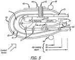
- FIG. 5depicts a longitudinal cross-section of sensing assembly 1 in which the skin 6 may be composed of three layers: outer layer 6a may be made of a textured dielectric material suitable for cosmesis, 6b may be made of a conductive material such as a metal-filled polymer, and 6c may be a thin, inner layer made of a soft dielectric material such as some silicone elastomers. Said layers may be formed by successive dip-coating to staggered depths as illustrated, using core 2 as a mandrel.
- Conductive skin layer 6bmay be dip-coated so as to make electrical contact with common electrode 8z, as depicted schematically in Figure 6 .
- Core 2may be equipped with capillary tube 46 which is used to introduce pulp 4 under pressure to inflate skin 6 away from core 2.
- fill tube 46can be connected to pressure transducer 29, which may be useful particularly to detect small, high frequency fluctuations in pressure in pulp 4 such as might be caused by vibration arising from sliding the textured outer surface of skin 6a over textured objects.
- skin 6may be retained by O-ring 48 against core 2 to prevent loss of pressurized material from pulp 4.
- core 2may have a removable section 2a that provides access to install detection circuitry 20, leads 10 to the inner surfaces of electrodes 8 and 9, and such other components as may be desired.
- removable section 2a of core 2may be equipped with a tension member 42 by which finger nail 40 can be compressed against skin 6 by retaining member 44. This arrangement may provide improved cosmesis and contributes to the specialized sensitivity of electrodes such as electrode 8a which is near the edge of finger nail 40.
- detection circuitry 20may be configured according to the electronic schematic illustrated in Figure 6 .
- Energization signal 22may be an AC voltage that is applied to common electrode 8z and thus to conductive skin layer 6b.
- the capacitance between each sensing electrode 8a, b... and conductive skin layer 6bmay constitute the electrical impedance 24 that changes as the thickness of the dielectric pulp 4 between these elements changes in response to contact forces.
- a small fraction of the voltage of the energization signal 22may be detected on each of sensing electrodes 8a, b... by detection circuitry 20.
- the data from all sensing electrodes, pressure transducer, and other sensors that may be incorporatedmay be combined and serialized by multiplexor 28 and transmitted to analysis logic 30.
- the positioning of the electrodes 8 with respect to the contours of the core 2 and overlying pulp 4 and skin 6may cause distinct patterns of change in the various impedances 24 measured by the detection circuitry 20 as the sensor assembly 1 contacts various objects and surfaces with various force vectors.
- Analysis logic 30may incorporate feature extraction algorithms to make inferences about the nature of the contact according to the patterns so detected. It may be useful to identify how different aspects of any particular stimulus parameter to be sensed will influence the array of electrodes comprising the sensor assembly 1. If such influences result in sufficiently distinct output patterns across all of the elements of the sensor, then it may be feasible to employ algorithms known as neural networks that may function similar to those embodied in the nervous system in order to identify the nature of the contact state in terms of feature of contacted objects and spatiotemporal distribution of contact forces.
- FIG. 7illustrates a configuration in which the serialized sensor data from the sensor assembly 1 may be processed by analysis logic 30 consisting of an input demultiplexor 32 that provides data to the input layer of neural network 34.
- the output layer 36may provide control signals 37a-c to actuators 38 that operate the articulations of the mechanical hand 39. Movements of the mechanical hand 39 may give rise to changes in the contact forces between the fingers and external objects to be gripped, which results in changing signals from the sensor assembly 1.
- the neural network 34may consist of a matrix of connectivity between input and output signals embodied as gains in a hidden layer.
- the neural network 34may be trained to produce the desired transformation between input and output signals by iteratively and systematically adjusting those gains according to training signal 35 derived from comparisons between the responses of the mechanical hand 39 and a dataset of observations of normal human hands manipulating similar objects under similar conditions.
- the examplesare all described with reference to the first exemplary embodiment in which the pulp 4 may be a moderately resistive volume conductor and the skin 6 is a dielectric, but similar feature extraction algorithms can be applied to the temporospatial patterns of impedance that can be measured by the sensor assembly for the various alternate embodiments described above, as will be obvious to one normally skilled in the art.
- FIG. 4a cross-sectional view along axis A-A as denoted in Figure 1 , which represents only one of many such parallel cross-sections, each potentially containing a plurality of electrodes and related circuitry.
- the changes in electrical impedance 24are discussed in the context of the first preferred embodiment presented in Figures 1-4 in which decreases in the distance between skin 6 and electrodes 8a, b,... may produce increases in electrical impedance 24. In other embodiments, changes in distance may give rise to different but detectable changes in electrical impedance 24, which can be related to stimulus features by variants of detection circuitry 20 and analysis logic 30 that would be obvious to one normally skilled in the art.
- the pulp 4may be squeezed laterally into the region near the seal 7 at the perimeter note increasing space between skin 6 and electrodes 8 at positions a and b.
- the pulp 4 overlying the electrodes 8 in the compressed central area of the sensor assembly 1becomes thinner, causing the impedance measurements associated with those electrodes to become higher note decreased space between skin 6 and electrodes 8 at positions d, e and f.
- the sum of all such impedance increasesis related to the total force of contact; that sum will be dominated by the nonlinear increase in impedance as electrodes approach the skin.
- the impedance increases associated with the contact force measurement abovecan be related to the position of the electrodes 8 in the array in order to estimate where the center of force is located on the surface of the sensor assembly and the radius of curvature of the contacting object. For example, a sharp object might produce a local deformation of the skin that would cause large changes of impedance for only one or a few electrodes close to the point of contact. If the pulp 4 is an incompressible material, any decrease in its thickness over one or more electrodes 8 may be accompanied by a bulging increase in its thickness over other electrodes 8 at a distance from the region of contact.
- the distribution of impedance changes detected by the electrodeswill be similarly asymmetrical. This asymmetry can be detected to make inferences about the shape of the contacting object.
- the force between the sensor assembly 1 and the contacted objectmay not be oriented normal to the surface of the sensor assembly 1.
- shear force componentschange the stress and strain distributions within the fingertip that are sensed by receptors located within dermal and subdermal tissues but also by the distribution of pressure around the perimeter of the finger pad, particularly where the skin is anchored by the nail bed. This is described in the above-referenced and incorporated journal article (Birznieks, Jenmalm, Goodwin & Johansson 2001).
- those electrodes 8 located on the most convex portions of the core 2 near the seals 7 of the skin 6may detect large increases in impedance when shear forces are directed away from them (see electrodes at positions h and i in Figure 4 ). Such force may cause the skin 6 to slide, compressing the pulp 4 over these electrodes.
- a deviation of the force vector from normalmay generally be associated with a tendency of the grasped object to slip or rotate unless that deviation met by increased normal forces or is opposed by the net deviations at other points of contact with the object, as described in the above-referenced journal articles (Flanagan, Burstedt & Johansson 1999 ; Johansson & Westling 1984).
- the detection of imminent slipis essential to the maintenance of efficient and effective grip on objects, in which it may be generally desirable to produce only the minimal force on the object required to initiate and maintain stable grasp.
- imminent slipis detected by localized, tiny shifts in the distribution of shear forces in the skin.
- the relationship between electrode impedance and thickness of the overlying pulpmay be inherently highly nonlinear, as described above. For example, if the inner surface of the nonconductive, elastomeric skin actually touches and covers an electrode, its impedance with respect to any other contact may increase abruptly towards infinity.
- the distribution of impedances across the array of electrodesmay undergo large changes when the skin is compressed against the core.
- the impedance 24 of the electrode 8 at position ewould be highest because one textural element 5 is sized and positioned so as to completely cover it, while somewhat lower but nearly equal impedances would be measured for electrodes at positions d and f, which are incompletely covered by adjacent textural elements 5.
- Even a small lateral shift or stretch of skin 6would reposition the three textural elements 5 with respect to all three electrodes, producing a large and readily detectable change in the pattern of impedances measured.
- the systemmay be configured to detect the onset of any change in the shear force distribution, rather than the actual shear forces or the direction of the change.
- the appropriate response to the imminent slip implied by any such changeis an increase in the grip force applied to the object as described in the above-referenced journal article (Johansson & Westling 1987).
- Biological skincontains specialized Pacinian receptors that are highly sensitive to the acceleration component of skin deformation, making them useful to detect transient mechanical events that occur when making and breaking contact between a held object such as a tool and another object, and vibration of skin induced by the motion of skin ridges sliding over a textured object surface.
- the impedance of the electrodes in embodiments of the present systemmay undergo only very small changes when lightly loaded, but it may be possible to detect such changes by means of their synchronous phasing across the entire array of electrodes.
- Various signal averaging techniques to enhance the detection of the correlated component of weak and noisy signals from an array of sensorsare well known in the prior art.
- the hydrostatic pressure in pulp 4can be monitored by a conventional pressure transducer 29 connected to fill tube 46.
- the detection of transient mechanical eventsmay be a key component in the automatic control of most object manipulations, which are organized around sequentially linked action phases delimited by discrete contact events that represent attainment of task subgoals. This is described in the above-referenced journal article (Westling & Johansson 1987).
- One commonly used signal processing technique to enhance the detection and timing of transient events in electrical signalsmay be the computation of temporal derivatives, which can be performed by analog circuits and digital signal processing algorithms that are well-known to electrical engineers.
Landscapes
- Engineering & Computer Science (AREA)
- Physics & Mathematics (AREA)
- General Physics & Mathematics (AREA)
- Chemical & Material Sciences (AREA)
- Analytical Chemistry (AREA)
- Power Engineering (AREA)
- Human Computer Interaction (AREA)
- Robotics (AREA)
- Mechanical Engineering (AREA)
- Force Measurement Appropriate To Specific Purposes (AREA)
- Measurement Of The Respiration, Hearing Ability, Form, And Blood Characteristics Of Living Organisms (AREA)
- Manipulator (AREA)
Description
- This patent application the claims the benefit of the filing date of
US provisional application Serial No. 60/786,607, filed March 28, 2006 - Field of the Invention: This application relates generally to devices and methods to provide a set of sensory feedback information capabilities from robotic or prosthetic finger tips comparable to those provided by the human skin.
- General Background and State of the Art: Present generations of robots lack most of the sensorial abilities of humans. This limitation prevents industrial robots from being used to carry on delicate tasks of enormous practical relevance (such as assembly operations) and, even more, it prevents the development of evoluted robots for off-factory jobs (agriculture, home, assistance to the disabled, etc). Future generations of robots may be increasingly featured by the massive use of dedicated sensors that will enhance substantially the limited ability of present robots to interact with the external world. Taction, vision and proximity are the sensory needs that, in combination or alone, are commonly accepted as desirable features of robots. Research on visual pattern recognition received considerable attention in recent years. Tactile recognition (the ability to recognize objects by manipulation) is an inherently active process. Unlike visual sensors (passive and located remotely from the object), tactile sensors must be put in contact with the object to be recognized and, even more, such contact should be competently organized in order to extract the maximum degree of information from manipulative acts.
- Humans who have suffered amputations of their hands and arms are generally provided with prosthetic limbs. Increasingly these prosthetics incorporate electromechanical actuators to operate articulations similar to biological joints, particularly to control the fingers to grasp and hold objects. Recent research has revealed how arrays of biological tactile receptors distributed throughout the soft tissues of the finger tip are used normally by the nervous system to provide rapid adjustments of grip force. Due to limitations in currently available tactile sensing technology discussed below, currently available prosthetic fingers provide little or no sensing capabilities and cannot make use of these highly effective biological control strategies.
- Tactile sensors are generally known and can be grouped into a number of different categories depending upon their construction, the most common groups are piezoresistive, piezoelectric, capacitive and elastoresistive structures. The common feature of all of these devices is the transduction of local asperities (unevenness or a projection from a surface) into electrical signals. Tactile sensors are commonly used in the field of robotics and in particular with those robotic devices which pick up and place objects in accordance with programmed instructions; the so-called "pick and place" class of robot. Unfortunately, while it would be desirable for the above-listed groups of tactile sensors to respond in much the same way that the human finger does, many of them can provide only limited information about a contact with an object. This requires large numbers of separate structures or electrical characteristics that require extensive circuitry in order to obtain an output indicative of the surface which has been contacted. For robotics, the difficulties associated with their non-linear response mechanisms, their fragile structure, and the high cost of assembling many discrete components limits their use of the above groups in an industrial environment. There are difficulties with calibration, environmental survivability, and other factors which render them less than optimal for many applications in less restricted environments, particularly those associated with motor-actuated prosthetic hands and telerobotic systems intended to augment human performance.
- An example of an impedance tomographic tactile sensor is disclosed in
US 4,980,646 A . - In a first aspect, the invention provides a biomimetic tactile sensor for providing an electrical indication of contact comprising a substantially rigid core having a curved surface, configured to hold a plurality of electrodes along the curved surface, wherein each of the electrodes is independently energized; at least one deformable layer, configured to attach to the core, having an inner and an outer surface; a volume of deformable material enclosed between the core and the at least one deformable layer inner surface; and a detection circuitry mounted within the core and electrically coupled to the plurality of the electrodes, configured to independently energize at least one of the electrodes and detect contact information independently from the energized electrode, wherein the contact information corresponds to a local force that is exerted on the deformable layer outer surface.
- In a second aspect, the invention provides a biomimetic tactile sensor for providing an electrical indication of contact comprising a substantially rigid core having a curved surface, configured to hold a plurality of electrodes along the curved surface; at least one deformable layer, configured to attach to the core, having an inner and an outer surface; a volume of deformable material enclosed between the core and the at least one deformable layer inner surface made of a volume-conductive liquid; and detection circuitry electrically coupled to the plurality of the electrodes and configured to detect changes in the electrical impedance of the volume-conductive liquid between electrodes caused by force exerted on the deformable layer outer surface.
- Optionally, the detected contact information from the electrode is a measured impendance.
- Optionally, the detection circuit is further configured to transmit the measured impedance to an external processor.
- Optionally, the deformable material is a dielectric material selected from a group including gases, liquids and gels.
- Optionally, the deformable material is an electrical conducting material selected from a group including aqueous gels; non-aqueous gels and liquid crystal materials.
- Optionally, the deformable material is volume-conducting material.
- Optionally, the core is made from a material selected from group including titanium, aluminum, stainless steel, zirconia ceramic and alumina ceramic.
- Optionally, the deformable layer is made from a dielectric material.
- Optionally, the deformable layer is made from electrical conductive material.
- Optionally, the deformable layer is made from a material including any one of a woven metal fabric, metal-filled polymer and carbon-filled polymer.
- Optionally, the detection circuitry is configured to determine contact information from the plurality of the electrodes that are held by the core.
- Optionally, the detected contact information from the electrode is a measured capacitance.
- In a further aspect the invention provides a biomimetic tactile sensor for providing an electrical indication of contact comprising a substantially rigid core having a curved surface, configured to hold a plurality of electrodes along the curved surface; at least one deformable layer having an inner and an outer surface, wherein the inner surface has at least one protruding element configured to attach to the core, and wherein the at least one protruding element is substantially opposed to at least one of the electrodes; a volume of deformable material enclosed between the core and the at least one deformable layer inner surface; and a detection circuitry mounted within the core, configured to detect a contact information from the at least one electrode.
- Optionally the detection circuitry is configured to detect information corresponding to a force exerted on the deformable layer outer surface.
- Optionally, the detection circuitry is configured to detect contact information corresponding to a normal force exerted on the deformable layer outer surface.
- Optionally, the detection circuitry is configured to detect contact information corresponding to a tangential force exerted on the deformable layer outer surface.
- Optionally the detection circuitry is configured to detect contact information corresponding to a shear force exerted on the deformable layer outer surface.
- Optionally the detected contact information from the electrode is a measured impedance.
- Optionally, the deformable material is injected through a channel into the space between the deformable layer inner surface and the core.
- Optionally, the deformable material is a dielectric material selected from a group including gas, liquid and gel.
- Optionally, the deformable material is an electrical conducting material selected from a group including aqueous gel, non-aqueous gel and liquid crystal material.
- Optionally, the deformable material is a volume-conducting material.
- Optionally, the core is made from a material selected from a group including titanium, aluminum, stainless steel, zirconia ceramic and alumina ceramic.
- Optionally, the deformable layer is made from a dielectric material.
- The biomimetic tactile sensor, wherein the deformable layer is made from material selected from a group including polymers and polyurethanes.
- Optionally, the protruding element forms a bump and/or ridge on the inner surface of the deformable layer.
- Optionally, the deformable layer is made from electrical conductive material.
- Optionally, the deformable layer is made from a material including any one of a woven metal fabric, metal-filled polymer or carbon-filled polymer.
- The biomimetic tactile sensor preferably further comprises a plurality of deformable layers.
- Optionally, the at least one deformable layer is formed by dip-coating.
- Optionally, the detection circuitry is configured to determine contact information from the plurality of the electrodes.
- Optionally, the detected contact information from the electrode is a measured capacitance
- Optionally, the detected contact information from the electrode is a measured impedance.
- Optionally, the detection circuitry is configured to measure the impedance from the plurality of the electrodes.
- Optionally, the system further comprises a channel located within the core, configured to inject the deformable material.
- Optionally, the deformable material is inflated through the channel.
- Optionally, the detecting circuitry is configured to detect changes in measured impedances among and/or from the plurality of the electrodes.
- Optionally, the deformable material is a dielectric.
- Optionally, the deformable material is an electrical conductive material.
- Optionally, the measured impedance is capacitance between the deformable layer and the electrode that are separated by a dielectric deformable material.
- Optionally, the measured impedance is resistance between a deformable layer and the electrode separated by a weakly conductive deformable material.
- Optionally, the deformable layer is a dielectric.
- The system wherein the deformable layer is an electrical conductor.
- Optionally, the energizing comprises applying a direct voltage or current.
- In a yet further aspects the invention provides a biomimetic tactile sensory system for activating a prosthetic/disabled hand to grip an object comprising a biomimetic tactile sensor configured to determine a contact information comprising: a plurality of electrodes held on a curved surface of a core,
wherein each of the electrodes has a proximal and a distal end; an energizing circuitry configured to energize at least one of the plurality of electrodes, a volume of deformable material in contact with the plurality of the electrodes distal end; at least one deformable layer having an inner and outer surface, configured to cover the deformable material; a detection circuitry configured to determine a contact information from the at least one energized electrode and sending the determined contact information; a processor configured to receive the sent contact information in order to identify at least one characteristic of a contact by the object based on the detected contact information and a feature extraction algorithm; and at least one actuator configured to activate the prosthetic/disabled hand based on an output data generated by the feature extraction algorithm in order to grip the object. - Optionally, the detected contact information from the electrode is a measured impedances.
- Optionally, the detection circuitry is configured to measure impedance from the plurality of electrodes.
- Optionally, the feature extraction algorithm is a trainable neural network.
- Optionally, the biomimetic tactile sensor is an anatomical finger-like structure that is integrated into the prosthetic/disabled hand.
- Optionally, the finger-like structure configured to exert more force on the object in order to grip the object.
- Optionally, measured impedance from the plurality of electrodes change when the object is gripped.
- Optionally, the characteristic of the contact corresponds to any one of contact force, centroid and area of force, eccentricity of force, vector of force, vernier detection of force shifts; or contact transients and vibration.
- Optionally, the reformable material is a dielectric.
- Optionally, ithe deformable material is an electrical conductor.
- Optionally, the measured impedance is capacitance between the deformable layer and the electrode separated by to dielectric deformable material.
- Optionally, the measured impedance is resistance between the deformable layer and the electrode separated by a weakly conductive deformable material.
- Optionally, the deformable layer is a dielectric.
- Optionally, the deformable layer is an electrical conductor.
- Optionally, the biomimetic sensor further comprising a plurality of deformable layers.
- Optionally, the deformable layer further comprising at least one protruding element positioned onto the inner surface, wherein the protruding element is substantially opposed to at least one of the electrodes.
- Optionally, the detection circuitry produces a large change in impedance based on a lateral shift of the protruding element.
- Optionally, the processor further is configured to determine if a slip of the object is imminent.
- Optionally, the system further comprises a plurality of biomimetic tactile sensors having anatomical finger-like structure that are integrated into the prosthetic/disabled hand.
- In a yet further aspect, the invention provides a method of determining the characteristics of contact by an object against a deformable surface of a biomimetic tactile sensor comprising: energizing at least one electrode from a plurality of electrodes held on a curved surface of a substantially rigid core of a the tactile sensor, wherein the electrode has a proximal and a distal end and wherein the at least one electrode distal and is in contact with a deformable material; detecting contact information from the at least one energized electrode; and sending the contact information to a processor in order to identify at least one characteristic of a contact based on the detected contact information and a feature extraction algorithm.
- Optionally, the detected contact information from the electrode is a measured impedance
- Optionally, the energizing includes energizing a plurality of the electrodes and detecting contact information from them.
- Optionally, the feature extraction algorithm is a trainable algorithm.
- Optionally, the trainable algorithm is a neural network.
- Optionally, the characteristic of the contact is identified based at least on one feature of the object and spatiotemporal distribution of applied forces by the object against the reformable layer.
- Optionally, the characteristic of the contact corresponds to any one of contact force, centroid and area of force, eccentricity of force, vector of force, vernier detection of force shifts, or contact transients and vibration.
- Optionally, the measured impedance comprises capacitance between a conductive deformable layer of the tactile sensor and the electrodes, and wherein the deformable layer and the electrodes are separated by a dielectric deformable material.
- Optionally, the measured impedance is resistance between a conductive deformable layer and the electrodes separated by a weakly conductive deformable material.
- Optionally, the detecting comprises detection of impedances between one electrode and other electrodes.
- Optionally, the detecting comprises measurement of impedance between combination of the electrodes.
- Optionally, the detecting comprises measurement of impedances from each of the electrodes.
- In a yet further aspect, the invention provides a biomimetic tactile sensory system for determining the characteristics of contact by an object against a deformable surface comprising: a) a biomimetic tactile sensor configured to determine a contact information comprising: i) a plurality of electrodes held on a curved surface of a core, wherein each of the electrodes has a proximal and a distal end; ii) an energizing circuitry held within the core, configured to energize at least one of the plurality of electrodes, iii) a volume of deformable material in contact with the plurality of the electrodes distal end; iv) at least one deformable layer having an inner and outer surface, configured to cover the deformable material; v) a detection circuitry held within the core, configured to determine a contact information from the at least one energized electrode and sending the determined contact information; and b) a processor configured to receive the sent contact information in order to identify at least one characteristic of a contact by the object based on the detected contact information and a feature extraction algorithm.
- The present biomimetic tactile sensor may possess softness, elasticity and some mechanical resistance that mimics natural human skin. Furthermore, it may detect and discriminate various aspects of contact with external objects, including the direction and magnitude of force, the extent and shape of the object, and small movements associated with impending slip.
- An exemplary embodiment comprises a device through which a set of information is generated concerning tactile interaction between a manipulator and an object to be manipulated and recognized. The tactile information may be generated either by robot or prosthetic finger tips. A key feature of the embodiment may be that it confers a very high sensitivity to incremental changes in the distribution of pressure.
- The sensory device may have a biomimetic shape of the core and covering skin and pulp that results in distinctive and readily detectable patterns of impedance changes across an array of electrodes disposed on the core, to take advantage of the various distortions of the pulp produced by the contact parameters to be detected and discriminated. Because of the overall biomimetic design of the sensor assembly, the stimulus features that may be most readily detected by the feature extraction circuitry are those features that may be most useful for automatic adjustment of contact force to achieve and maintain stable and efficient grasp of an object. Features of disclosed sensory devices that may be associated with this strategy include the complex mechanical contours of the core, the elasticity and points of attachment of the investing skin, the specific shapes and dispositions of the electrodes on the core surface, conditions of use in which at least some electrodes are nearly or completely occluded by direct contact with the overlying skin, and the extraction of information from complex temporospatial patterns of impedance changes among those electrodes using trainable algorithms such as neural networks.
- Exemplary sensory devices may also include a sensor assembly whose basic form and function are similar to that of a human finger tip. A prosthetic hand or anthropomorphic robotic manipulandum could combine several such finger tips at the ends of appendages whose movements may be controlled by actuators. Similar padlike structures with sensors might also be deployed on grip contact surfaces akin to the palmar eminences over the heads of the metacarpal bones etc. One or more such sensor assemblies could be built with various sizes and shapes and mounted in varying numbers and positions on a variety of manipulanda, locomotor supports and other mechanical apparatus that must interact with external objects and surfaces according to information derived from contact sensors.
- One embodiment of the present device may consist of a set of sensors that work by measuring the electrical impedance among a plurality of electrodes. The electrodes may be deployed on a substantially rigid core that is protected from direct contact with external objects by overlying deformable structures. A feature of this design may be the location of mechanically vulnerable connections between the electrodes and the signal processing circuitry, which are wholly contained within the substantially rigid core. A related feature may be that this design enables methods of manufacture and repair that are simple and efficient.
- The plurality of sensors and their associated mechanical structures have similarities to the biological relationships among the cutaneous neural receptors, the distal phalanx, overlying finger pulp and covering skin and nail. Information may be extracted from such a plurality of sensors whereby such information can be related to canonical physical representations used to describe stimuli to be sensed, and/or used to control automatic adjustments of grip forces similar to the neural reflexes whereby humans maintain stable grip on complex objects.
- It is understood that other embodiments of the biomimetic tactile sensor systems and methods will become readily apparent to those skilled in the art from the following detailed description, wherein it is shown and described only exemplary embodiments by way of illustration. As will be realized, the biomimetic tactile sensor systems and methods are capable of other and different embodiments and its several details are capable of modification in various other respects. Accordingly, the drawings and detailed description are to be regarded as illustrative in nature and not as restrictive.
Figure 1 shows a longitudinal cross-section of a tactile sensor in the form of a finger pad.Figure 2 shows a schematic of the electronic system for signal detection and processing.Figure 3 shows a cross-sectional detail of a scheme for automated routing and connection of electrodes to electronic circuitry.Figure 4 shows a transverse cross-section of a tactile sensor responding to a typical contact force.Figure 5 shows a longitudinal cross-section of a tactile sensor in the form of a finger pad and which employs variable-capacitance sensing.Figure 6 shows a schematic of the electronic system for signal detection for a tactile sensor array that employs variable-capacitance sensing.Figure 7 shows a schematic of a neural network trained to adjust grip forces according to feedback from the tactile sensor.- The detailed description set forth below is intended as a description of exemplary embodiments of the tactile sensory system and method and is not intended to represent the only embodiments in which the biomimetic tactile sensor systems and methods can be practiced. The term "exemplary" used throughout this description means "serving as an example, instance, or illustration," and should not necessarily be construed as preferred or advantageous over other embodiments. The detailed description includes specific details for the purpose of providing a thorough understanding of the tactile sensory systems and methods. However, it will be apparent to those skilled in the art that the tactile sensory systems and methods may be practiced without these specific details. In some instances, well-known structures and devices are shown in block diagram form in order to avoid obscuring the concepts of the tactile sensory systems and methods.
- It is a general property of biological sensory receptors that they are highly evolved structures in which the receptors themselves and the tissues in which they are located may contain many features designed to enhance their sensitivity and the quantity of information that they can provide to the central nervous system. The skin contains multiple types of mechanoreceptors to transduce a variety of mechanical events that occur during contact with physical objects. These receptors are concentrated in sites such as the finger tips, where their sensitivity is enhanced by the mechanical properties of the skin, underlying pulp and bone, and adjacent fingernails.
US Patent 4,980,646 , to Zemel, is incorporated herein by reference and teaches a tactile sensor based on changes in the local electrical resistance presented by a layer of weakly conductive fluid whose shape is deformed by external forces applied to a deformable membrane. Zemel describes the application of a voltage gradient across the entire extent of the fluid by means of electrodes arranged on either side of the array of sensing strips, and the measurement of the local strength of that gradient by differential voltage measurements between adjacent pairs of electrode strips.US patent 4,555,953 to Dario et al. , which is incorporated by reference in its entirety, teaches different techniques and materials that have been utilized for the construction of artificial skin-like sensors. - The input-output properties of these biological transducers differ generally from engineered transducers. Engineered transducers are usually designed to produce a linear response to a single mechanical variable such as normal or tangential force at a single point. The signals from arrays of such transducers can be combined according to simple, analytical algorithms to extract orthogonal physical parameters of touch such as total force, center of force, directional force vector and two-point resolution. Biological touch receptors are highly nonlinear and nonorthogonal. Their signals are combined by adaptive neural networks to provide subconscious adjustment of motor output as well as high level conscious perception associated with haptic identification of objects. Neurophysiologists and psychologists often correlate the activity of somatosensory receptors and design measures of psychophysical percepts according to canonical physical parameters, but there is little evidence that the nervous system actually extracts direct representations of such parameters as an intermediate stage between sensation and performance. In fact, information theory suggests that such an intermediate representation would add noise and reduce information content, which would place such a strategy at an evolutionary disadvantage. Engineered sensors and their signal processing systems use linear, orthogonal representations because the downstream control systems generally have been based on such inputs. This strategy may work well for engineered systems such as industrial robots that must perform accurately for highly constrained and predictable tasks. It is difficult to apply to anthropomorphic robots and prosthetic limbs that must perform a broad and unpredictable range of tasks associated with activities of daily living. The problem may further be complicated by environmental factors in such environments (e.g. temperature, moisture, sharp edges etc.), which tend to damage or bias sensitive and/or physically exposed transducers.
- Exemplary embodiments of the present sensory devices have features comparable to features found in biological systems. In particular, they may use biomimetic mechanical structures similar to those found in the finger tip to endow a set of simple, robust electronic sensors with a wide range of modalities and sensitivities similar to those found in biological mechanoreceptors. An exemplary embodiment may employ a larger number of small, local electrodes deployed in a curved array whose shape and mechanical properties mimic those of a biological finger tip. Each sensing electrode may be energized to provide an independent measure of the local mechanical deformations of the overlying membrane based on its impedance with respect to a remote common electrode. Further improvements are described to enhance the sensitivity and dynamic range of each sensing electrode by contouring the inner surface of the overlying membrane. Yet another exemplary embodiment teaches a novel method of detecting deformation of the membrane by energizing the membrane and detecting the capacitive coupling to each sensing electrode through a dielectric fluid or gas. In further embodiments, neural networks may compute directly the actuator adjustments required to maintain stable grip of objects with a variety of shapes and force vectors in a manner similar to that employed by neural control of the human hand.
- Various aspect of the present exemplary biomimetic sensing devices can incorporate features described in the following articles, which are all incorporated herein by reference:Johansson RS, Westling G. ("Signals in tactile afferents from the fingers eliciting adaptive motor responses during precision grip", Experimental Brain Research. 66:141-154, 1987 );Westling G, Johansson RS. "Responses in glabrous skin mechanoreceptorsd during precision grip in humans", Experimental Brain Research. 66:128-140, 1987);Flanagan JR, Burstedt MKO, Johansson RS "Control of fingertip forces in multi-digit manipulation" Journal of Neurophysiology. 81:1706-1717, 1999);Birznieks I, Jenmalm P, Goodwin AW, Johansson RS. "Encoding of direction of fingertip forces by human tactile afferents" Journal of Neuroscience. 21:8222-8237, 2001);Johansson RS, Birznieks "First spikes in ensembles of human tactile afferents code complex spatial fingertip events" Nature Neuroscience 7:170-177, 2004) which are all incorporated by reference in their entirety.
- Referring to
Figure1 , thesensor assembly 1 may consist of a substantially rigidcentral core 2 surrounded by apulp 4 with fluid, elastic or gel mechanical properties, covered by askin 6 attached to thecore 2 by means of aseal 7 along the perimeter of thepad 12 thereby created. A plurality ofelectrodes 8 may be deployed on those surfaces of thecore 2 whose contact with objects and surfaces is to be sensed, as described below.US patent 4,980,646 to Zemel discusses an alternative tactile sensor design which may be implemented in embodiments of the present tactile sensors. - The
skin 6 may be a deformable and/or elastic material similar to human glabrous skin in its mechanical properties and possessing advantageous properties such as toughness to resist wear, texture and tackiness to improve grip, and colorizable for cosmesis. As described below, it may be advantageous to incorporate bumps, ridges and/or other features into the internal and/or external surface(s) of the skin. Suitable materials may include but are not limited to polymers such as silicone elastomers and polyurethanes, among many others familiar to biomedical engineers and prosthetists. In a preferred embodiment, thecore 2 may be made of a mechanically tough material such as zirconia ceramic or titanium metal that can function as part of the mechanical linkage of the prosthesis or robot on which the sensor assembly is deployed. The following references, which are incorporated by reference in their entirety, teach various features that may be utilized in the present tactile sensor devices and methods:US Patent 6,871,395 to Scher et al. teaches connecting electrically conductive elastomer to electronics andUS Patent 6,529,122 to Magnussen et al. teaches measuring contact resistance between workpieces,US Patent 5,905,430 to Yoshino et al. for detecting state of contact between a contact member and a workpiece,US Patent 5,033,291 to Podoloff et al. for flexible tactile sensor for measuring foot pressure distributions;US patent 5,014,224 to Hans for determining location and amount of exerted pressure;US Patent 4,817,440 to Curtin for identifying contact force and the contact pattern;US Patent 4,526,043 to Boie et al. for Conformable tactile sensor; andUS Patent 4,481,815 to Overton for determining a parameter of an object being contacted by the tactile sensor. - In one exemplary embodiment, the choice of material for the
pulp 4 may be chosen to be a deformable, volume-conductive liquid or gel whose electrical conductivity is sufficiently low that the resistance measured between two or more electrodes in contact with the pulp changes when the pulp is mechanically deformed. Suitable materials may include aqueous and nonaqueous gels with ionic conductors, liquid crystal materials, and many others that would be obvious to one normally skilled in the art. Advantageously, thepulp 4 can be injected through a hypodermic needle into the space between theskin 6 and thecore 2 and itselectrodes 8 after theskin 6 is attached to theseal 7. This makes it possible to control accurately the thickness and pressure of thepulp 4 and to refurbish thesensor assembly 1 by replacing theskin 6 and/orpulp 4 without affecting theelectrodes 8 ordetection circuitry 20. - Sensing may be accomplished by measuring changes in the electrical impedance among
electrodes 8 whose distribution and location on the contoured surface of thecore 2 may be a key factor in the sensing properties of thesensor assembly 1. One embodiment ofdetection circuitry 20 is illustrated schematically inFigure 2 and described in more detail below. Theelectrical impedance 24 so measured can be dominated by the thickness and electrical properties of thepulp 4. For some of the various configurations described in more detail below, this may be a resistance that can be measured between a givenelectrode 8 and other electrodes or reference points and that depends generally on the inverse of the distance between saidelectrode 8 and theskin 6 immediately overlying saidelectrode 8. This distance may decrease because of pressure on the overlying skin but increases because of hydrostatic pressure in theviscoelastic pulp 4. If theskin 6 completely occludes anelectrode 8, theelectrical impedance 24 may become very large and insensitive to further increases in contact force, which may be undesirable. This problem can be mitigated by texturing the inner surface ofskin 6. Such texture may be created ifskin 6 is formed by the method of dip-coating and polymerization in situ as described below, in which case the surfaces ofcore 2 andelectrodes 8 can be abraded prior to dip-coating to create the desired textured surface. - The
sensing assembly 1 may have the greatest sensitivity to a small change in the distribution of pressure in those electrodes that are near the edge of a population ofelectrodes 8 in which theskin 6 has been compressed against the central electrodes of the population. Such a change may cause electrodes along this edge to change between the states of having a small distance between skin and electrode to having a zero distance, for which the resistance theoretically becomes infinite. Other embodiments are described below in which the impedance measured at anelectrode 8 decreases as the distance between theelectrode 8 and theskin 6 decreases. - Each
electrode 8 may be electrically insulated from the others and from the overlyingpulp 4 except for a specifically defined contact area with the pulp comprising theelectrode 8. Eachelectrode 8 may be connected todetection circuitry 20 by means of alead 10. This can be accomplished by various feedthroughs and coatings such as are commonly employed in hybrid microelectronic circuits and hermetic packages.Figure1 illustrates one embodiment in which thecore 2 may be a dielectric material such as zirconia or alumina ceramic and theelectrodes 8 consist of metallic vias that pass through laser-drilled holes in the ceramic and are connected todetection circuitry 20 by means ofleads 10 consisting of conventional wirebonds. In another embodiment illustrated inFigure3 , conductive lines may be printed on the outside and/or inside surface of thecore 2 providing a means for forming theleads 10 so that thedetection circuitry 20 can be connected to the plurality ofelectrodes 8 by means of a plurality ofwelds 14 made directly and simultaneously to the backs of conductive feedthrough pins9 using methods such as flip-chip and ball-grid array bonding, as is well-known in the art. In yet another embodiment, thecore 2 may be a metallic material such as titanium, aluminum or stainless steel and theelectrodes 8 consist of the external surfaces of metal feedthroughs that pass through holes drilled through thecore 2. Theelectrodes 8 may be held in place by a seal made from a dielectric material such as a melted glass frit that can provide both electrical insulation between theelectrodes 8 and a hermetic seal between the liquid component of thepulp 4 and thedetection circuitry 20. Detection circuitry 20 may be mounted within a recess in thecore 2 that provides mechanical support and protection. As illustrated schematically inFigure 2 , saiddetection circuitry 20 convertspower supply 21 to anenergization signal 22 that may be applied to various combinations ofelectrodes 8. Theimpedances 24 of the effective circuit between theelectrodes 8 through thepulp 4 may be quantified bymeasurement circuits 26 and reported toanalysis logic 30. If the pulp is an electron conductor, then theenergization signal 22 can be a direct current or voltage; the measured value may be a direct voltage or current, respectively. Theimpedance 24 of the volume conductive path through thepulp 4 may be dominated by its resistive component, which can be computed from Ohm's law. If thepulp 4 may be an ionic conductor such as an aqueous solution or gel, then theenergization signal 22 may advantageously be an alternating current or voltage that avoids electrolysis and polarization effects on theelectrodes 8. The magnitude of the measured alternating voltage or current can be extracted by rectifying and low pass filtering to compute theimpedance 24 of the volume conductive path according to Ohm's law.- One alternative mode of operation of the
sensor assembly 1 may be to detect small changes in the distribution of pressure, which as noted above that may tend to produce the greatest incremental change inimpedances 24 among the subpopulation ofelectrodes 8 that are in or near contact with the overlyingskin 6. The incremental sensitivity of thedetection circuitry 20 to such changes may be different for the two modes of measurement just described. If theenergization signal 22 is a voltage, then the measured current asymptotically approaches zero as the thickness of the overlying pulp decreases when it is compressed with increasing contact force. If theenergization signal 22 is a current, then the measured voltage exponentially may rise toward the compliance voltage of the available power supply as the thickness of the overlying pulp is compressed towards the contact. These two relationships have implications for the detectability of incremental changes by the subsequent feature algorithms of theanalysis logic 30 as described below. Any signal detection should cope with the inevitable consequences of electrical noise in the various electrically active and passive components such as are well-known to those normally skilled in the art. - One exemplary configuration for impedance measurement may be between each
electrode 8 and a common contact (designated by the ground symbol inFig. 2 ) that substantially surrounds all of theelectrodes 8. The common contact may be printed photolithographically onto the surface of thecore 2 if it is a dielectric material or formed by thecore 2 itself if it is a conductive material. Alternatively, the common contact may be formed by conductive material incorporated into theseal 7 surrounding theelectrodes 8 as depicted inFigure 4 . Many other configurations can be created dynamically by incorporating electronic switches into thedetection circuitry 20. Among these configurations may be differential measurements between a pair ofadjacent electrodes 8, measurements between oneelectrode 8 and all other electrodes connected together by said switches, and differential measurements between various combinations ofelectrodes 8 selected dynamically by means of said switches. - In yet another exemplary embodiment, the
pulp 4 can be a volume conductor with a fairly high resistivity such as 100(ohm)(cm) and theskin 6 can be a conductor that is connected to the "ground" or reference voltage of the detection circuitry. In this case, theelectrical impedance 24 between eachelectrode 8 and theskin 6 may be approximately proportional to the distance between them, declining rapidly to approximately zero as they actually touch each other. Still other combinations of conductive and dielectric materials for thepulp 4 andskin 6 andrelated detection circuitry 20 are included within the scope of the system. - In an alternate embodiment, the
pulp 4 can be made from a dielectric material and theskin 6 can be an electrical conductor such as a woven metal fabric or metal- or carbon-filled polymer. Suitable dielectric materials for thepulp 4 may include but are not limited to gases such as air, liquids such as mineral oil, and gels such as silicone polymers. In this embodiment, theimpedance 24 between eachelectrode 8 and theoverlying skin 6 may be essentially that of a capacitor whose value increases with the inverse of the distance between theelectrode 8 and theoverlying skin 6. Thus, the mechanical factors in the design and performance of thesensor assembly 1 may be generally similar to those of the first embodiment in which thepulp 4 is a conductor and theskin 6 is a dielectric. The impedance of a capacitor is related inversely to the value of its capacitance and inversely to the frequency of the electrical signal applied to it. In this alternate embodiment, the impedance between any one ormore electrodes 8 and theskin 6 may be readily measured by applying anenergization signal 22 between them that may be an alternating current or voltage and measuring the alternating voltage or current, respectively. It may generally be advantageous for theskin 6 to be connected to the "ground" or reference voltage for all of theindividual detection circuits 20 associated with thevarious electrodes 8. - In the above alternate embodiment, if such a
conductive skin 6 actually touches anelectrode 8, theimpedance 24 between them may go abruptly to approximately zero because of ohmic conductance between them. If that is not desired, such contact can be prevented and the maximal value of the capacitance between them can be stabilized by coating the inside surface of the conductive skin with a thin and flexible dielectric layer such as poly-paraxylylene (commercial tradename Parylene). If theskin 6 is composed of a woven metal fabric, a vapor-deposited coating of Parylene on both the inside and outside surface of theskin 6 can advantageously be used to seal the fabric so that the dielectric material used for thepulp 4 does not leak out and to avoid making electrical contact with external objects. - Yet another exemplary embodiment in which the deformation of the
skin 6 andpulp 4 may be detected as variable capacitance as illustrated inFigures 5 and6 .Figure 5 depicts a longitudinal cross-section ofsensing assembly 1 in which theskin 6 may be composed of three layers:outer layer 6a may be made of a textured dielectric material suitable for cosmesis,6b may be made of a conductive material such as a metal-filled polymer, and6c may be a thin, inner layer made of a soft dielectric material such as some silicone elastomers. Said layers may be formed by successive dip-coating to staggered depths as illustrated, usingcore 2 as a mandrel.Conductive skin layer 6b may be dip-coated so as to make electrical contact withcommon electrode 8z, as depicted schematically inFigure 6 .Core 2 may be equipped withcapillary tube 46 which is used to introducepulp 4 under pressure to inflateskin 6 away fromcore 2. Optionally, filltube 46 can be connected to pressuretransducer 29, which may be useful particularly to detect small, high frequency fluctuations in pressure inpulp 4 such as might be caused by vibration arising from sliding the textured outer surface ofskin 6a over textured objects. At its proximal edge,skin 6 may be retained by O-ring 48 againstcore 2 to prevent loss of pressurized material frompulp 4. Advantageously,core 2 may have aremovable section 2a that provides access to installdetection circuitry 20, leads10 to the inner surfaces ofelectrodes 8 and9, and such other components as may be desired. Optionally,removable section 2a ofcore 2 may be equipped with atension member 42 by whichfinger nail 40 can be compressed againstskin 6 by retainingmember 44. This arrangement may provide improved cosmesis and contributes to the specialized sensitivity of electrodes such aselectrode 8a which is near the edge offinger nail 40. - For use in the variable
capacitance sensing assembly 1 illustrated inFigure 5 ,detection circuitry 20 may be configured according to the electronic schematic illustrated inFigure 6 .Energization signal 22 may be an AC voltage that is applied tocommon electrode 8z and thus toconductive skin layer 6b. The capacitance between each sensingelectrode 8a, b... andconductive skin layer 6b may constitute theelectrical impedance 24 that changes as the thickness of thedielectric pulp 4 between these elements changes in response to contact forces. A small fraction of the voltage of theenergization signal 22 may be detected on each ofsensing electrodes 8a, b... bydetection circuitry 20. The data from all sensing electrodes, pressure transducer, and other sensors that may be incorporated (e.g. temperature sensors) may be combined and serialized bymultiplexor 28 and transmitted toanalysis logic 30. - The positioning of the
electrodes 8 with respect to the contours of thecore 2 andoverlying pulp 4 andskin 6 may cause distinct patterns of change in thevarious impedances 24 measured by thedetection circuitry 20 as thesensor assembly 1 contacts various objects and surfaces with various force vectors.Analysis logic 30 may incorporate feature extraction algorithms to make inferences about the nature of the contact according to the patterns so detected. It may be useful to identify how different aspects of any particular stimulus parameter to be sensed will influence the array of electrodes comprising thesensor assembly 1. If such influences result in sufficiently distinct output patterns across all of the elements of the sensor, then it may be feasible to employ algorithms known as neural networks that may function similar to those embodied in the nervous system in order to identify the nature of the contact state in terms of feature of contacted objects and spatiotemporal distribution of contact forces. That is, neural networks can be trained by learning to respond in a useful manner to those features of any stimulus that must be discriminated.Figure 7 illustrates a configuration in which the serialized sensor data from thesensor assembly 1 may be processed byanalysis logic 30 consisting of aninput demultiplexor 32 that provides data to the input layer ofneural network 34. Theoutput layer 36 may providecontrol signals 37a-c to actuators38 that operate the articulations of themechanical hand 39. Movements of themechanical hand 39 may give rise to changes in the contact forces between the fingers and external objects to be gripped, which results in changing signals from thesensor assembly 1. Theneural network 34 may consist of a matrix of connectivity between input and output signals embodied as gains in a hidden layer. Theneural network 34 may be trained to produce the desired transformation between input and output signals by iteratively and systematically adjusting those gains according totraining signal 35 derived from comparisons between the responses of themechanical hand 39 and a dataset of observations of normal human hands manipulating similar objects under similar conditions. - The following is an exemplary list of stimulus features, their effects on the
electrical impedances 24 may be measured amongvarious electrodes 8, and associated feature extraction algorithms that can be incorporated or trained into saidanalysis logic 30. The examples are all described with reference to the first exemplary embodiment in which thepulp 4 may be a moderately resistive volume conductor and theskin 6 is a dielectric, but similar feature extraction algorithms can be applied to the temporospatial patterns of impedance that can be measured by the sensor assembly for the various alternate embodiments described above, as will be obvious to one normally skilled in the art. Most are illustrated with reference toFigure 4 , a cross-sectional view along axisA-A as denoted inFigure 1 , which represents only one of many such parallel cross-sections, each potentially containing a plurality of electrodes and related circuitry. The changes inelectrical impedance 24 are discussed in the context of the first preferred embodiment presented inFigures 1-4 in which decreases in the distance betweenskin 6 andelectrodes 8a, b,... may produce increases inelectrical impedance 24. In other embodiments, changes in distance may give rise to different but detectable changes inelectrical impedance 24, which can be related to stimulus features by variants ofdetection circuitry 20 andanalysis logic 30 that would be obvious to one normally skilled in the art. - As the total force increases on central area of the
sensor assembly 1, thepulp 4 may be squeezed laterally into the region near theseal 7 at the perimeter note increasing space betweenskin 6 andelectrodes 8 at positionsa andb. Thepulp 4 overlying theelectrodes 8 in the compressed central area of thesensor assembly 1 becomes thinner, causing the impedance measurements associated with those electrodes to become higher note decreased space betweenskin 6 andelectrodes 8 at positionsd, e andf. The sum of all such impedance increases is related to the total force of contact; that sum will be dominated by the nonlinear increase in impedance as electrodes approach the skin. - The impedance increases associated with the contact force measurement above can be related to the position of the
electrodes 8 in the array in order to estimate where the center of force is located on the surface of the sensor assembly and the radius of curvature of the contacting object. For example, a sharp object might produce a local deformation of the skin that would cause large changes of impedance for only one or a few electrodes close to the point of contact. If thepulp 4 is an incompressible material, any decrease in its thickness over one ormore electrodes 8 may be accompanied by a bulging increase in its thickness overother electrodes 8 at a distance from the region of contact. - If the contacting object is not radially symmetrical, the distribution of impedance changes detected by the electrodes will be similarly asymmetrical. This asymmetry can be detected to make inferences about the shape of the contacting object.
- In most object-manipulation tasks, the force between the
sensor assembly 1 and the contacted object may not be oriented normal to the surface of thesensor assembly 1. In biological skin, shear force components change the stress and strain distributions within the fingertip that are sensed by receptors located within dermal and subdermal tissues but also by the distribution of pressure around the perimeter of the finger pad, particularly where the skin is anchored by the nail bed. This is described in the above-referenced and incorporated journal article (Birznieks, Jenmalm, Goodwin & Johansson 2001). - In an exemplary embodiment, those
electrodes 8 located on the most convex portions of thecore 2 near theseals 7 of theskin 6 may detect large increases in impedance when shear forces are directed away from them (see electrodes at positionsh and i inFigure 4 ). Such force may cause theskin 6 to slide, compressing thepulp 4 over these electrodes. A deviation of the force vector from normal may generally be associated with a tendency of the grasped object to slip or rotate unless that deviation met by increased normal forces or is opposed by the net deviations at other points of contact with the object, as described in the above-referenced journal articles (Flanagan, Burstedt & Johansson 1999 ; Johansson & Westling 1984). - The detection of imminent slip is essential to the maintenance of efficient and effective grip on objects, in which it may be generally desirable to produce only the minimal force on the object required to initiate and maintain stable grasp. In the biological fingertip, imminent slip is detected by localized, tiny shifts in the distribution of shear forces in the skin. The relationship between electrode impedance and thickness of the overlying pulp may be inherently highly nonlinear, as described above. For example, if the inner surface of the nonconductive, elastomeric skin actually touches and covers an electrode, its impedance with respect to any other contact may increase abruptly towards infinity. By incorporating protruding
textural elements 5 such as bumps and ridges onto the inner surface of anelastomeric skin 6, the distribution of impedances across the array of electrodes may undergo large changes when the skin is compressed against the core. InFigure4 , theimpedance 24 of theelectrode 8 at position e would be highest because onetextural element 5 is sized and positioned so as to completely cover it, while somewhat lower but nearly equal impedances would be measured for electrodes at positionsd andf, which are incompletely covered by adjacenttextural elements 5. Even a small lateral shift or stretch ofskin 6 would reposition the threetextural elements 5 with respect to all three electrodes, producing a large and readily detectable change in the pattern of impedances measured. In an exemplary embodiment, the system may be configured to detect the onset of any change in the shear force distribution, rather than the actual shear forces or the direction of the change. The appropriate response to the imminent slip implied by any such change is an increase in the grip force applied to the object as described in the above-referenced journal article (Johansson & Westling 1987). - Biological skin contains specialized Pacinian receptors that are highly sensitive to the acceleration component of skin deformation, making them useful to detect transient mechanical events that occur when making and breaking contact between a held object such as a tool and another object, and vibration of skin induced by the motion of skin ridges sliding over a textured object surface. The impedance of the electrodes in embodiments of the present system may undergo only very small changes when lightly loaded, but it may be possible to detect such changes by means of their synchronous phasing across the entire array of electrodes. Various signal averaging techniques to enhance the detection of the correlated component of weak and noisy signals from an array of sensors are well known in the prior art. Alternatively as depicted in
Figures 5 and6 , the hydrostatic pressure inpulp 4 can be monitored by aconventional pressure transducer 29 connected to filltube 46. The detection of transient mechanical events may be a key component in the automatic control of most object manipulations, which are organized around sequentially linked action phases delimited by discrete contact events that represent attainment of task subgoals. This is described in the above-referenced journal article (Westling & Johansson 1987). One commonly used signal processing technique to enhance the detection and timing of transient events in electrical signals may be the computation of temporal derivatives, which can be performed by analog circuits and digital signal processing algorithms that are well-known to electrical engineers. It is within the scope of our system to apply such techniques to the signals obtainable from the sensors described herein in order to enhance the utility of the tactile information so derived. Examples of the extraction and use of temporal cues by biological tactile systems can be found in the above-referenced journal article (Johansson & Birznieks 2004). - The previous description of the disclosed embodiments is provided to enable any person skilled in the art to make or use the tactile sensory systems and methods. Various modifications to these embodiments will be readily apparent to those skilled in the art, and the generic principles defined herein may be applied to other embodiments without departing from the scope of the tactile sensory systems and methods as defined in the claim. Thus, the tactile sensory systems and methods are not intended to be limited to the embodiments shown herein but are to be accorded the widest scope consistent with the principles and novel features disclosed herein.
Claims (14)
- A biomimetic tactile sensor for providing an electrical indication of contact comprising:a) a substantially rigid core having a curved surface, configured to hold a plurality of electrodes along the curved surface;b) at least one deformable layer, configured to attach to the core, having an inner and an outer surface;c) a volume of deformable material enclosed between the core and the at least one deformable layer inner surface made of a conductive liquid; andd) detection circuitry electrically and independently coupled to the plurality of the electrodes and configured to detect changes in the electrical impedance of the conductive liquid between electrodes caused by force exerted on the deformable layer outer surface.
- The sensor of claim 1 further comprising a pressure transducer located within the core to monitor the pressure of the space occupied by the deformable material.
- The sensor of claim 2, wherein the pressure transducer is configured to detect vibrations of the deformable layer induced by motion of the deformable layer sliding over a surface of an object in contact with the deformable layer.
- The sensor of claim 1, wherein the biomimetic tactile sensor includes a temperature sensor.
- The sensor of claims 1-4, further comprising a controller configured to control movement of a prosthetic hand or robotic manipulator that is attached to the biomimetic tactile sensor based on information from the biomimetic tactile sensor.
- The sensor of claim 5, wherein the control movement includes changing a gripping force of the robotic hand or robotic manipulator.
- The sensor of claim 1, wherein the detection circuitry is configured to apply an alternating voltage or current to the electrodes.
- The biomimetic tactile sensor of claim 1, wherein the deformable layer includes bumps, ridges or other forms of texturing on the inner surface of the deformable layer.
- The sensor of claim 1, wherein the detection circuitry is configured to detect a normal force exerted on the outer surface of the deformable layer.
- The sensor of claim 1 wherein the detection circuitry is configured to detect a shear force exerted on the outer surface of the deformable layer.
- The sensor of claim 1 further comprising a processor configured to identify at least one characteristic of an object that is in contact with the deformable layer based on the detected changes in the electrical impedance and a feature extraction algorithm.
- The sensor of claim 11, wherein the feature extraction algorithm utilizes information from the pressure transducer recited in claim 2 and/or the temperature sensor recited in claim 4.
- The sensor of claim 11 and 12, wherein the the feature extraction algorithm is a trainable algorithm.
- The sensor of claims 11 through 13, wherein the characteristic of the contact corresponds to any one of contact force, centroid and area of force, eccentricity of force, vector of force, vernier detection of force shifts, or contact transients and vibration.
Applications Claiming Priority (2)
| Application Number | Priority Date | Filing Date | Title |
|---|---|---|---|
| US78660706P | 2006-03-28 | 2006-03-28 | |
| PCT/US2007/007631WO2007126854A2 (en) | 2006-03-28 | 2007-03-28 | Biomimetic tactile sensor |
Publications (3)
| Publication Number | Publication Date |
|---|---|
| EP2010868A2 EP2010868A2 (en) | 2009-01-07 |
| EP2010868A4 EP2010868A4 (en) | 2013-06-12 |
| EP2010868B1true EP2010868B1 (en) | 2017-01-18 |
Family
ID=38656033
Family Applications (1)
| Application Number | Title | Priority Date | Filing Date |
|---|---|---|---|
| EP07754188.6AActiveEP2010868B1 (en) | 2006-03-28 | 2007-03-28 | Biomimetic tactile sensor |
Country Status (3)
| Country | Link |
|---|---|
| US (1) | US7658119B2 (en) |
| EP (1) | EP2010868B1 (en) |
| WO (1) | WO2007126854A2 (en) |
Families Citing this family (67)
| Publication number | Priority date | Publication date | Assignee | Title |
|---|---|---|---|---|
| US8033189B2 (en)* | 2005-12-28 | 2011-10-11 | Honda Motor Co., Ltd. | Robot skin |
| EP2010868B1 (en) | 2006-03-28 | 2017-01-18 | University of Southern California | Biomimetic tactile sensor |
| US7878075B2 (en)* | 2007-05-18 | 2011-02-01 | University Of Southern California | Biomimetic tactile sensor for control of grip |
| US8181540B2 (en) | 2006-03-28 | 2012-05-22 | University Of Southern California | Measurement of sliding friction-induced vibrations for biomimetic tactile sensing |
| US8272278B2 (en) | 2007-03-28 | 2012-09-25 | University Of Southern California | Enhancements to improve the function of a biomimetic tactile sensor |
| WO2009124211A1 (en)* | 2008-04-02 | 2009-10-08 | University Of Southern California | Enhancements to improve the function of a biomimetic tactile sensor |
| US8588977B2 (en)* | 2008-11-20 | 2013-11-19 | University Of Utah Research Foundation | Signal modulator for visual indicator |
| WO2010099210A2 (en)* | 2009-02-24 | 2010-09-02 | University Of Southern California | Flexible polymer-based encapsulated-fluid devices |
| US9222819B2 (en) | 2009-02-20 | 2015-12-29 | University Of Southern California | Tracking and controlling fluid delivery from chamber |
| JP5445065B2 (en) | 2009-11-25 | 2014-03-19 | セイコーエプソン株式会社 | Shear force detection element, tactile sensor, and gripping device |
| JP5679541B2 (en)* | 2010-01-26 | 2015-03-04 | 株式会社デルタツーリング | Biological signal detection device |
| FI20105197L (en)* | 2010-03-01 | 2011-09-02 | Numcore Oy | PROBE THAT DETECTS INTERFACES BETWEEN SUBSTANCES |
| WO2012015077A1 (en) | 2010-07-27 | 2012-02-02 | 한국과학기술연구원 | Material screening apparatus |
| EP2598942A4 (en) | 2010-07-30 | 2014-07-23 | Univ Leland Stanford Junior | CONDUCTIVE FILMS |
| EP2605710B1 (en) | 2010-08-18 | 2015-10-21 | Deutsches Zentrum für Luft- und Raumfahrt e. V. | Minimally invasive instrument |
| US9281415B2 (en) | 2010-09-10 | 2016-03-08 | The Board Of Trustees Of The Leland Stanford Junior University | Pressure sensing apparatuses and methods |
| US9228822B2 (en) | 2011-01-24 | 2016-01-05 | President And Fellows Of Harvard College | Non-differential elastomer curvature sensor |
| GB201114264D0 (en) | 2011-08-18 | 2011-10-05 | Touch Emas Ltd | Improvements in or relating to prosthetics and orthotics |
| CN107300435B (en) | 2011-09-24 | 2019-11-01 | 哈佛大学校长及研究员协会 | Artificial skin and elastic strain sensor |
| US9239346B2 (en) | 2012-01-28 | 2016-01-19 | The Regents Of The University Of California | Systems for providing electro-mechanical sensors |
| CA2863197A1 (en) | 2012-03-08 | 2013-09-12 | Quality Manufacturing Inc. | Touch sensitive robotic gripper |
| US9605952B2 (en) | 2012-03-08 | 2017-03-28 | Quality Manufacturing Inc. | Touch sensitive robotic gripper |
| TWM444569U (en)* | 2012-07-27 | 2013-01-01 | Seda Chemical Products Co Ltd | Non aware type activity sensing device with conductive elastomer |
| US11737896B2 (en) | 2012-07-31 | 2023-08-29 | Purdue Research Foundation | Wirelessly-powered implantable EMG recording system |
| WO2014043037A1 (en) | 2012-09-11 | 2014-03-20 | SynTouch, LLC | Compliant tactile sensor with fluid-filled, sponge-like material |
| JP6111589B2 (en)* | 2012-10-11 | 2017-04-12 | セイコーエプソン株式会社 | Robot hand, robot apparatus, and method of manufacturing robot hand |
| TW201416652A (en)* | 2012-10-18 | 2014-05-01 | Ind Tech Res Inst | Pressure sensing device and clipping apparatus using the same |
| US9797791B2 (en) | 2012-10-27 | 2017-10-24 | President And Fellows Of Harvard College | Multi-axis force sensing soft artificial skin |
| US9851708B2 (en)* | 2012-11-06 | 2017-12-26 | Koninklijke Philips N.V. | Sensor for moving equipment |
| GB201302025D0 (en) | 2013-02-05 | 2013-03-20 | Touch Emas Ltd | Improvements in or relating to prosthetics |
| US9625333B2 (en) | 2013-03-15 | 2017-04-18 | President And Fellows Of Harvard College | Tactile sensor |
| EP3007867B1 (en) | 2013-06-11 | 2020-10-21 | OnRobot A/S | Systems and methods for sensing objects |
| US9839534B2 (en) | 2014-02-04 | 2017-12-12 | Rehabilitation Institute Of Chicago | Modular and lightweight myoelectric prosthesis components and related methods |
| GB201403265D0 (en) | 2014-02-25 | 2014-04-09 | Touch Emas Ltd | Prosthetic digit for use with touchscreen devices |
| GB201408253D0 (en) | 2014-05-09 | 2014-06-25 | Touch Emas Ltd | Systems and methods for controlling a prosthetic hand |
| US9460638B2 (en) | 2014-06-30 | 2016-10-04 | Jeff Baker | Smart injection training device and system |
| US20160025615A1 (en)* | 2014-07-22 | 2016-01-28 | SynTouch, LLC | Method and applications for measurement of object tactile properties based on how they likely feel to humans |
| GB201417541D0 (en) | 2014-10-03 | 2014-11-19 | Touch Bionics Ltd | Wrist device for a prosthetic limb |
| US9808936B2 (en)* | 2015-08-03 | 2017-11-07 | Massachusetts Institute Of Technology | Two-phase gripper to reorient and grasp |
| US10718359B2 (en) | 2015-08-21 | 2020-07-21 | Quality Manufacturing Inc. | Devices and systems for producing rotational actuation |
| US20180243924A1 (en)* | 2015-09-08 | 2018-08-30 | The Regents Of The University Of California | Tactile sensors and methods of fabricating tactile sensors |
| EP3455599B1 (en) | 2016-05-13 | 2021-12-22 | Sensobright Industries, LLC | A practical sensing system |
| TR201606363A2 (en)* | 2016-05-13 | 2017-11-21 | Sensobright Ind Llc | A multifunction detection system. |
| CN107717981B (en)* | 2016-08-12 | 2021-01-05 | 财团法人工业技术研究院 | Control device of mechanical arm and teaching system and method thereof |
| EP3506857B1 (en) | 2016-09-02 | 2025-07-09 | Touch Bionics Limited | Systems and methods for prosthetic wrist rotation |
| US11185426B2 (en) | 2016-09-02 | 2021-11-30 | Touch Bionics Limited | Systems and methods for prosthetic wrist rotation |
| US11346727B2 (en)* | 2016-09-27 | 2022-05-31 | Sony Corporation | Sensor, electronic device, wearable terminal, and control method |
| US10663361B2 (en) | 2016-10-13 | 2020-05-26 | The Trustees Of Columbia University In The City Of New York | Systems and methods for tactile sensing |
| CA3067367A1 (en) | 2017-06-15 | 2018-12-20 | Onrobot Los Angeles Inc. | Systems, devices, and methods for sensing locations and forces |
| CN110997252A (en)* | 2017-08-10 | 2020-04-10 | Thk株式会社 | Manipulator mechanism and gripping system |
| CN111093914B (en)* | 2017-08-14 | 2023-01-03 | 肯塔泰尔私人有限公司 | Friction-based tactile sensor for measuring clamping safety |
| US10973660B2 (en) | 2017-12-15 | 2021-04-13 | Touch Bionics Limited | Powered prosthetic thumb |
| CN112204501A (en)* | 2018-02-28 | 2021-01-08 | 陈维达 | Wearable gesture recognition device and related operating method and system |
| US11547581B2 (en) | 2018-12-20 | 2023-01-10 | Touch Bionics Limited | Energy conservation of a motor-driven digit |
| US11478185B2 (en) | 2019-02-12 | 2022-10-25 | Hill-Rom Services, Inc. | Skin dressing having sensor for pressure ulcer prevention |
| CN113853181A (en) | 2019-04-10 | 2021-12-28 | 塔驰仿生有限公司 | Prosthetic fingers with articulated links |
| US11312581B2 (en)* | 2019-04-16 | 2022-04-26 | Abb Schweiz Ag | Object grasp system and method |
| US20210125052A1 (en)* | 2019-10-24 | 2021-04-29 | Nvidia Corporation | Reinforcement learning of tactile grasp policies |
| US11931270B2 (en) | 2019-11-15 | 2024-03-19 | Touch Bionics Limited | Prosthetic digit actuator |
| EP4165561A4 (en) | 2020-06-15 | 2024-07-17 | National University of Singapore | Event-driven visual-tactile sensing and learning for robots |
| US12115087B2 (en) | 2020-11-03 | 2024-10-15 | Touch Bionics Limited | Sensor for prosthetic control |
| CN113916416B (en)* | 2021-09-23 | 2023-05-16 | 北京科技大学 | High-permeability strain non-sensitive electronic skin and preparation method thereof |
| CN114593847A (en)* | 2022-03-24 | 2022-06-07 | 轻昂化学(深圳)有限公司 | Series connected flexible sensor structure |
| CN115523943A (en)* | 2022-10-28 | 2022-12-27 | 南京理工大学 | Flexible multi-modal touch sensing system based on non-grid sensing plane |
| CN116749217A (en)* | 2023-05-12 | 2023-09-15 | 苏州大学 | A bionic tactile mechanism, robot dexterous hand and robot |
| US20250128402A1 (en) | 2023-10-20 | 2025-04-24 | Tacta Systems Inc. | Tactile robotic training platform |
| US12410053B1 (en) | 2024-07-29 | 2025-09-09 | Tacta Systems Inc. | Embedded digital sensor structure |
Family Cites Families (117)
| Publication number | Priority date | Publication date | Assignee | Title |
|---|---|---|---|---|
| US4014217A (en)* | 1975-11-28 | 1977-03-29 | Agence Nationale De Valorisation De La Recherche Etablissement Public De Droit | Tactile pick-up |
| US4306148A (en) | 1980-01-21 | 1981-12-15 | General Electric Company | Tactile sensor |
| US4521685A (en) | 1982-03-01 | 1985-06-04 | Lord Corporation | Tactile sensor for an industrial robot or the like |
| DE3236098A1 (en) | 1982-09-29 | 1984-03-29 | Siemens AG, 1000 Berlin und 8000 München | PRESSURE CONVERTER ARRANGEMENT, ESPECIALLY FOR INDUSTRIAL ROBOTS |
| US4481815A (en) | 1982-12-23 | 1984-11-13 | Overton Kenneth J | Tactile sensor |
| US4492949A (en) | 1983-03-18 | 1985-01-08 | Barry Wright Corporation | Tactile sensors for robotic gripper and the like |
| US4526043A (en) | 1983-05-23 | 1985-07-02 | At&T Bell Laboratories | Conformable tactile sensor |
| US4555953A (en)* | 1984-04-16 | 1985-12-03 | Paolo Dario | Composite, multifunctional tactile sensor |
| US4584625A (en) | 1984-09-11 | 1986-04-22 | Kellogg Nelson R | Capacitive tactile sensor |
| US4964302A (en) | 1984-09-25 | 1990-10-23 | Grahn Allen R | Tactile sensor |
| US4621533A (en) | 1984-11-19 | 1986-11-11 | Eaton Corporation | Tactile load sensing transducer |
| US4555954A (en) | 1984-12-21 | 1985-12-03 | At&T Technologies, Inc. | Method and apparatus for sensing tactile forces |
| US4634917A (en) | 1984-12-26 | 1987-01-06 | Battelle Memorial Institute | Active multi-layer piezoelectric tactile sensor apparatus and method |
| US4616511A (en) | 1985-02-20 | 1986-10-14 | Eaton Corporation | Tactile sensor |
| US4715235A (en)* | 1985-03-04 | 1987-12-29 | Asahi Kasei Kogyo Kabushiki Kaisha | Deformation sensitive electroconductive knitted or woven fabric and deformation sensitive electroconductive device comprising the same |
| US4813732A (en) | 1985-03-07 | 1989-03-21 | Epsilon Technology, Inc. | Apparatus and method for automated wafer handling |
| US4640137A (en) | 1985-05-31 | 1987-02-03 | Lord Corporation | Tactile sensor |
| NL8501908A (en) | 1985-07-03 | 1987-02-02 | Tno | PROBE SENSOR. |
| US4817440A (en) | 1985-10-18 | 1989-04-04 | The Board Of Governors For Higher Education, State Of Rhode Island And Providence Plantations | Compliant tactile sensor |
| JPH0676931B2 (en) | 1986-01-13 | 1994-09-28 | 工業技術院長 | Tactile sensor |
| US4694231A (en) | 1986-04-18 | 1987-09-15 | Mecanotron Corporation | Robotic skin |
| GB8619800D0 (en) | 1986-08-14 | 1986-09-24 | Microelectronics Applic Resear | Tactile sensor device |
| US4945305A (en) | 1986-10-09 | 1990-07-31 | Ascension Technology Corporation | Device for quantitatively measuring the relative position and orientation of two bodies in the presence of metals utilizing direct current magnetic fields |
| US4745812A (en) | 1987-03-25 | 1988-05-24 | The United States Of America As Represented By The Secretary Of The Army | Triaxial tactile sensor |
| DE3715693C1 (en) | 1987-05-12 | 1988-09-01 | Deutsche Forsch Luft Raumfahrt | Flat, tactile sensor |
| WO1993014386A1 (en)* | 1987-11-05 | 1993-07-22 | Kikuo Kanaya | Distribution-type touch sensor |
| US4814562A (en) | 1987-11-13 | 1989-03-21 | University Of Arkansas | Electro-optic force and pressure transducer and sensor |
| US5255345A (en) | 1988-02-17 | 1993-10-19 | The Rowland Institute For Science, Inc. | Genetic algorithm |
| US4980646A (en) | 1988-03-30 | 1990-12-25 | The Trustees Of The University Of Pennsylvania | Impedance tomographic tactile sensor |
| EP0350638B1 (en) | 1988-07-14 | 1993-12-15 | Blomberg Robotertechnik GmbH | Tactile sensor |
| US5501498A (en)* | 1988-08-31 | 1996-03-26 | The Trustees Of The University Of Pennsylvania | Methods and apparatus for mechanically intelligent grasping |
| US5034645A (en) | 1989-01-13 | 1991-07-23 | Digital Equipment Corporation | Micro-beam tactile sensor for the measurement of vertical position displacement |
| US5033291A (en) | 1989-12-11 | 1991-07-23 | Tekscan, Inc. | Flexible tactile sensor for measuring foot pressure distributions and for gaskets |
| US5261266A (en) | 1990-01-24 | 1993-11-16 | Wisconsin Alumni Research Foundation | Sensor tip for a robotic gripper and method of manufacture |
| US5631861A (en) | 1990-02-02 | 1997-05-20 | Virtual Technologies, Inc. | Force feedback and texture simulating interface device |
| US5060527A (en)* | 1990-02-14 | 1991-10-29 | Burgess Lester E | Tactile sensing transducer |
| US5200679A (en) | 1990-02-22 | 1993-04-06 | Graham Douglas F | Artificial hand and digit therefor |
| US5209126A (en) | 1991-01-04 | 1993-05-11 | Bonneville Scientific | Force sensor |
| US5373747A (en) | 1991-03-30 | 1994-12-20 | Kabushiki Kaisha Toshiba | Robot hand and robot |
| US5237879A (en) | 1991-10-11 | 1993-08-24 | At&T Bell Laboratories | Apparatus for dynamically varying the resolution of a tactile sensor array |
| US5225959A (en) | 1991-10-15 | 1993-07-06 | Xerox Corporation | Capacitive tactile sensor array and method for sensing pressure with the array |
| US5312439A (en) | 1991-12-12 | 1994-05-17 | Loeb Gerald E | Implantable device having an electrolytic storage electrode |
| US5193539A (en) | 1991-12-18 | 1993-03-16 | Alfred E. Mann Foundation For Scientific Research | Implantable microstimulator |
| US5193540A (en) | 1991-12-18 | 1993-03-16 | Alfred E. Mann Foundation For Scientific Research | Structure and method of manufacture of an implantable microstimulator |
| US6963792B1 (en) | 1992-01-21 | 2005-11-08 | Sri International | Surgical method |
| US5313840A (en) | 1992-10-30 | 1994-05-24 | At&T Bell Laboratories | Tactile shear sensor using anisotropically conductive material |
| US5760530A (en)* | 1992-12-22 | 1998-06-02 | The United States Of America As Represented By The Secretary Of The Air Force | Piezoelectric tactile sensor |
| US5510812A (en) | 1994-04-22 | 1996-04-23 | Hasbro, Inc. | Piezoresistive input device |
| US5604314A (en) | 1994-10-26 | 1997-02-18 | Bonneville Scientific Incorporated | Triaxial normal and shear force sensor |
| EP0738200B1 (en) | 1994-11-09 | 2003-02-12 | Amada Company Limited | Shear force sensing system |
| US6690963B2 (en) | 1995-01-24 | 2004-02-10 | Biosense, Inc. | System for determining the location and orientation of an invasive medical instrument |
| US5563354A (en) | 1995-04-03 | 1996-10-08 | Force Imaging Technologies, Inc. | Large area sensing cell |
| US5695859A (en) | 1995-04-27 | 1997-12-09 | Burgess; Lester E. | Pressure activated switching device |
| DE19527957C1 (en) | 1995-07-29 | 1996-08-22 | Karlsruhe Forschzent | Optoelectronic tactile pressure sensor linked to data processor |
| US5871248A (en)* | 1995-09-26 | 1999-02-16 | University Of South Florida | Robot gripper |
| US6051017A (en) | 1996-02-20 | 2000-04-18 | Advanced Bionics Corporation | Implantable microstimulator and systems employing the same |
| NL1002907C2 (en) | 1996-04-19 | 1997-10-21 | Univ Delft Tech | Touch sensor and method for determining a shear force and slip with such a touch sensor. |
| DE19616952C1 (en) | 1996-04-27 | 1997-01-23 | Karlsruhe Forschzent | Tactile optoelectronic pressure sensor |
| JP3621782B2 (en) | 1996-06-21 | 2005-02-16 | 本田技研工業株式会社 | Force sensor device |
| FR2751490B1 (en) | 1996-07-17 | 1998-09-25 | Legrand Sa | TOUCH SENSOR, ESPECIALLY FOR ELECTRICAL EQUIPMENT |
| US5744953A (en) | 1996-08-29 | 1998-04-28 | Ascension Technology Corporation | Magnetic motion tracker with transmitter placed on tracked object |
| US5905485A (en) | 1997-02-13 | 1999-05-18 | Breed Automotive Technology, Inc. | Controller with tactile sensors and method of fabricating same |
| KR100219838B1 (en) | 1997-05-03 | 1999-09-01 | 박호군 | Tactile feedback device using electromagnetic tractive force |
| JP3053007B2 (en) | 1997-07-28 | 2000-06-19 | 日本電気株式会社 | Fingerprint sensor |
| SG96541A1 (en) | 1997-08-14 | 2003-06-16 | Inst Of Microelectronics | Design of a novel tactile sensor |
| US5953683A (en) | 1997-10-09 | 1999-09-14 | Ascension Technology Corporation | Sourceless orientation sensor |
| EP1060455A4 (en) | 1998-02-10 | 2002-08-07 | Ey Lab Inc | Reflectometry system with compensation for specimen holder topography and with lock-rejection of system noise |
| JP2000051156A (en) | 1998-06-02 | 2000-02-22 | Olympus Optical Co Ltd | Touch sensor signal processor |
| IL141755A0 (en) | 1998-09-04 | 2002-03-10 | Wolfe Res Pty Ltd | Medical implant system |
| AU2342000A (en) | 1998-09-11 | 2000-04-17 | Loquitor Technologies Llc | Generation and detection of induced current using acoustic energy |
| LU90309B1 (en)* | 1998-11-04 | 2000-05-05 | Iee Sarl | Passenger detector |
| DE19859779A1 (en) | 1998-12-23 | 2000-07-13 | Peer Schmidt | Process for recording dynamic touch information |
| JP3261653B2 (en) | 1999-07-07 | 2002-03-04 | 独立行政法人産業技術総合研究所 | Finger-mounted 6-axis force sensor |
| US6286226B1 (en) | 1999-09-24 | 2001-09-11 | Agere Systems Guardian Corp. | Tactile sensor comprising nanowires and method for making the same |
| US6624626B2 (en) | 1999-11-01 | 2003-09-23 | Polhemus Inc. | Method and apparatus for electromagnetic position and orientation tracking with distortion compensation employing modulated signal |
| US6400139B1 (en) | 1999-11-01 | 2002-06-04 | Polhemus Inc. | Methods and apparatus for electromagnetic position and orientation tracking with distortion compensation |
| US6501463B1 (en) | 1999-12-10 | 2002-12-31 | Siemens Technology -To-Business Center Llc | Electronic whiteboard system using a tactile foam sensor |
| US6443509B1 (en) | 2000-03-21 | 2002-09-03 | Friendly Robotics Ltd. | Tactile sensor |
| GB0009675D0 (en) | 2000-04-20 | 2000-06-07 | Ball Burnishing Mach Tools | Mechanical coupling devices |
| US6445284B1 (en) | 2000-05-10 | 2002-09-03 | Juan Manuel Cruz-Hernandez | Electro-mechanical transducer suitable for tactile display and article conveyance |
| US6815179B2 (en) | 2001-02-20 | 2004-11-09 | Mitsuo Ochi | Methods for measuring stiffness of cultured tissue, for determining transplant compatibility, for quality control, and for preparing transplant-compatible cultured tissue |
| US7016560B2 (en) | 2001-02-28 | 2006-03-21 | Lightwave Microsystems Corporation | Microfluidic control for waveguide optical switches, variable attenuators, and other optical devices |
| US6937033B2 (en) | 2001-06-27 | 2005-08-30 | Immersion Corporation | Position sensor with resistive element |
| US6528991B2 (en) | 2001-07-03 | 2003-03-04 | Ascension Technology Corporation | Magnetic position measurement system with field containment means |
| US6871395B2 (en) | 2001-08-06 | 2005-03-29 | Siemens Technology-To-Business Center, Llc. | Methods for manufacturing a tactile sensor using an electrically conductive elastomer |
| SE0102833D0 (en)* | 2001-08-27 | 2001-08-27 | Bergomed Ab | Drive device at a finger prosthesis |
| US6769313B2 (en) | 2001-09-14 | 2004-08-03 | Paricon Technologies Corporation | Flexible tactile sensor |
| US6888537B2 (en) | 2002-02-13 | 2005-05-03 | Siemens Technology-To-Business Center, Llc | Configurable industrial input devices that use electrically conductive elastomer |
| KR20050012802A (en) | 2002-06-19 | 2005-02-02 | 코닌클리케 필립스 일렉트로닉스 엔.브이. | Tactile device |
| JP3969228B2 (en) | 2002-07-19 | 2007-09-05 | 松下電工株式会社 | Mechanical deformation detection sensor, acceleration sensor using the same, and pressure sensor |
| FR2843742B1 (en)* | 2002-08-26 | 2005-10-14 | Commissariat Energie Atomique | MICROSTRUCTURE WITH FUNCTIONALIZED SURFACE BY LOCALIZED DEPOSITION OF A THIN LAYER AND METHOD OF MANUFACTURING THE SAME |
| US7103447B2 (en) | 2002-09-02 | 2006-09-05 | Sony Corporation | Robot apparatus, and behavior controlling method for robot apparatus |
| US6996456B2 (en) | 2002-10-21 | 2006-02-07 | Fsi International, Inc. | Robot with tactile sensor device |
| US6950979B2 (en) | 2003-03-20 | 2005-09-27 | Arraycomm Inc. | Low complexity encoder and decoder |
| JP3867709B2 (en) | 2003-03-26 | 2007-01-10 | ダイキン工業株式会社 | Thin film formation method |
| US7112755B2 (en) | 2003-05-21 | 2006-09-26 | Nitta Corporation | Pressure-sensitive sensor |
| EP1634052A4 (en) | 2003-06-06 | 2008-04-30 | Univ Illinois | DETECTION CHIP AND APPARATUS FOR TOUCH DETECTION AND / OR FLOW |
| GB0313794D0 (en)* | 2003-06-14 | 2003-07-23 | Univ Dundee | Tactile sensor assembly |
| US7066895B2 (en)* | 2003-06-30 | 2006-06-27 | Ethicon, Inc. | Ultrasonic radial focused transducer for pulmonary vein ablation |
| US6915701B1 (en) | 2003-07-18 | 2005-07-12 | Cleveland Medical Devices Inc. | Composite material for a sensor for measuring shear forces |
| US6955094B1 (en) | 2003-07-18 | 2005-10-18 | Cleveland Medical Devices Inc. | Sensor for measuring shear forces |
| US20050234292A1 (en) | 2003-08-25 | 2005-10-20 | Faulkner Roger W | Hydraulically driven vibrating massagers |
| US7366332B2 (en) | 2003-08-26 | 2008-04-29 | Nippon Telegraph And Telephone Corporation | Surface shape recognition sensor |
| US7321701B2 (en) | 2003-09-05 | 2008-01-22 | Authentec, Inc. | Infrared biometric finger sensor and associated methods |
| US7742036B2 (en) | 2003-12-22 | 2010-06-22 | Immersion Corporation | System and method for controlling haptic devices having multiple operational modes |
| US7367232B2 (en) | 2004-01-24 | 2008-05-06 | Vladimir Vaganov | System and method for a three-axis MEMS accelerometer |
| US7004039B1 (en) | 2004-02-17 | 2006-02-28 | The United States Of America As Represented By The Secretary Of The Navy | Ambient pressure compensated tactile sensor |
| JP2006020823A (en) | 2004-07-08 | 2006-01-26 | Omron Healthcare Co Ltd | Array type capacitive pressure pulse wave sensor and pulse wave measuring apparatus equipped with the same |
| US7433853B2 (en)* | 2004-07-12 | 2008-10-07 | Cardiac Pacemakers, Inc. | Expert system for patient medical information analysis |
| US7654956B2 (en) | 2004-07-13 | 2010-02-02 | Dexcom, Inc. | Transcutaneous analyte sensor |
| US6886415B1 (en) | 2004-08-03 | 2005-05-03 | Toshiba Electric Engineering Corporation | Tactile sensor and gripping robot using the same |
| US7373843B2 (en) | 2005-06-02 | 2008-05-20 | Fidelica Microsystems | Flexible imaging pressure sensor |
| JP4595727B2 (en) | 2005-07-22 | 2010-12-08 | ソニー株式会社 | External force estimation system, external force estimation method, and computer program |
| US8005526B2 (en) | 2005-08-31 | 2011-08-23 | The Regents Of The University Of Michigan | Biologically integrated electrode devices |
| US20070207903A1 (en)* | 2006-03-02 | 2007-09-06 | Csabai Julius S | Elastic exercise device |
| EP2010868B1 (en) | 2006-03-28 | 2017-01-18 | University of Southern California | Biomimetic tactile sensor |
| TWI306054B (en) | 2006-12-19 | 2009-02-11 | Ind Tech Res Inst | Tactile sensing device and an robotic apparatus using thereof |
- 2007
- 2007-03-28EPEP07754188.6Apatent/EP2010868B1/enactiveActive
- 2007-03-28WOPCT/US2007/007631patent/WO2007126854A2/enactiveApplication Filing
- 2007-03-28USUS11/692,718patent/US7658119B2/enactiveActive
Non-Patent Citations (1)
| Title |
|---|
| None* |
Also Published As
| Publication number | Publication date |
|---|---|
| US20070227267A1 (en) | 2007-10-04 |
| US7658119B2 (en) | 2010-02-09 |
| EP2010868A4 (en) | 2013-06-12 |
| EP2010868A2 (en) | 2009-01-07 |
| WO2007126854A3 (en) | 2008-07-31 |
| WO2007126854A2 (en) | 2007-11-08 |
Similar Documents
| Publication | Publication Date | Title |
|---|---|---|
| EP2010868B1 (en) | Biomimetic tactile sensor | |
| US7878075B2 (en) | Biomimetic tactile sensor for control of grip | |
| US8181540B2 (en) | Measurement of sliding friction-induced vibrations for biomimetic tactile sensing | |
| US8272278B2 (en) | Enhancements to improve the function of a biomimetic tactile sensor | |
| Wettels et al. | Biomimetic tactile sensor array | |
| Li et al. | Towards the sEMG hand: internet of things sensors and haptic feedback application | |
| Chen et al. | Tactile sensors for friction estimation and incipient slip detection—Toward dexterous robotic manipulation: A review | |
| Yi et al. | Biomimetic tactile sensors and signal processing with spike trains: A review | |
| Li et al. | Non-invasive stimulation-based tactile sensation for upper-extremity prosthesis: a review | |
| WO2009124209A1 (en) | Robust measurement of sliding friction-induced vibrations for biomimetic tactile sensing | |
| JP5187856B2 (en) | Tactile sensor | |
| Cutkosky et al. | Force and tactile sensing | |
| WO2019014243A1 (en) | CAPACITIVE AND TOUCH SENSORS AND METHODS OF DETECTION THEREOF | |
| Ke et al. | Fingertip tactile sensor with single sensing element based on FSR and PVDF | |
| Dahiya et al. | Tactile sensing for robotic applications | |
| De Rossi | Artificial tactile sensing and haptic perception | |
| JP2024528541A (en) | Force sensor and device incorporating force sensor | |
| Edin et al. | Bio-inspired approach for the design and characterization of a tactile sensory system for a cybernetic prosthetic hand | |
| Wettels et al. | Biomimetic tactile sensor for control of grip | |
| US20240272019A1 (en) | Liquid magnet sensor | |
| Nemah et al. | A hybrid haptic feedback stimulation device to recover the missing sensation of the upper limb amputees | |
| Zhang et al. | Development and experiment analysis of anthropomorphic prosthetic hand with flexible three-axis tactile sensor | |
| Lorussi et al. | Wearable sensing garment for posture detection, rehabilitation and tele-medicine | |
| Lang et al. | Adaptive Grasping of the Soft Prosthetic Hand via Tactile Feedback | |
| KR102850977B1 (en) | On-skin Electro-Active Auxetic Sensor Based Virtual Cognitive Interface Smart Soft Haptic/Sensing Suit |
Legal Events
| Date | Code | Title | Description |
|---|---|---|---|
| PUAI | Public reference made under article 153(3) epc to a published international application that has entered the european phase | Free format text:ORIGINAL CODE: 0009012 | |
| 17P | Request for examination filed | Effective date:20081022 | |
| AK | Designated contracting states | Kind code of ref document:A2 Designated state(s):AT BE BG CH CY CZ DE DK EE ES FI FR GB GR HU IE IS IT LI LT LU LV MC MT NL PL PT RO SE SI SK TR | |
| AX | Request for extension of the european patent | Extension state:AL BA HR MK RS | |
| RAP1 | Party data changed (applicant data changed or rights of an application transferred) | Owner name:THE UNIVERSITY OF SOUTHERN CALIFORNIA | |
| RAP1 | Party data changed (applicant data changed or rights of an application transferred) | Owner name:UNIVERSITY OF SOUTHERN CALIFORNIA | |
| A4 | Supplementary search report drawn up and despatched | Effective date:20110816 | |
| RIC1 | Information provided on ipc code assigned before grant | Ipc:G01D 7/00 20060101AFI20110809BHEP Ipc:G01L 1/20 20060101ALI20110809BHEP Ipc:G01D 5/165 20060101ALI20110809BHEP | |
| DA4 | Supplementary search report drawn up and despatched (deleted) | ||
| RIC1 | Information provided on ipc code assigned before grant | Ipc:G01D 5/165 20060101ALI20110822BHEP Ipc:G01L 1/20 20060101ALI20110822BHEP Ipc:G01D 7/00 20060101AFI20110822BHEP | |
| DAX | Request for extension of the european patent (deleted) | ||
| RA4 | Supplementary search report drawn up and despatched (corrected) | Effective date:20110816 | |
| RAP1 | Party data changed (applicant data changed or rights of an application transferred) | Owner name:UNIVERSITY OF SOUTHERN CALIFORNIA | |
| GRAP | Despatch of communication of intention to grant a patent | Free format text:ORIGINAL CODE: EPIDOSNIGR1 | |
| INTG | Intention to grant announced | Effective date:20160804 | |
| GRAS | Grant fee paid | Free format text:ORIGINAL CODE: EPIDOSNIGR3 | |
| GRAA | (expected) grant | Free format text:ORIGINAL CODE: 0009210 | |
| AK | Designated contracting states | Kind code of ref document:B1 Designated state(s):AT BE BG CH CY CZ DE DK EE ES FI FR GB GR HU IE IS IT LI LT LU LV MC MT NL PL PT RO SE SI SK TR | |
| REG | Reference to a national code | Ref country code:GB Ref legal event code:FG4D | |
| REG | Reference to a national code | Ref country code:CH Ref legal event code:EP | |
| REG | Reference to a national code | Ref country code:AT Ref legal event code:REF Ref document number:863170 Country of ref document:AT Kind code of ref document:T Effective date:20170215 | |
| REG | Reference to a national code | Ref country code:IE Ref legal event code:FG4D | |
| REG | Reference to a national code | Ref country code:DE Ref legal event code:R096 Ref document number:602007049578 Country of ref document:DE | |
| REG | Reference to a national code | Ref country code:NL Ref legal event code:MP Effective date:20170118 | |
| REG | Reference to a national code | Ref country code:LT Ref legal event code:MG4D | |
| REG | Reference to a national code | Ref country code:AT Ref legal event code:MK05 Ref document number:863170 Country of ref document:AT Kind code of ref document:T Effective date:20170118 | |
| PG25 | Lapsed in a contracting state [announced via postgrant information from national office to epo] | Ref country code:NL Free format text:LAPSE BECAUSE OF FAILURE TO SUBMIT A TRANSLATION OF THE DESCRIPTION OR TO PAY THE FEE WITHIN THE PRESCRIBED TIME-LIMIT Effective date:20170118 | |
| PG25 | Lapsed in a contracting state [announced via postgrant information from national office to epo] | Ref country code:LT Free format text:LAPSE BECAUSE OF FAILURE TO SUBMIT A TRANSLATION OF THE DESCRIPTION OR TO PAY THE FEE WITHIN THE PRESCRIBED TIME-LIMIT Effective date:20170118 Ref country code:GR Free format text:LAPSE BECAUSE OF FAILURE TO SUBMIT A TRANSLATION OF THE DESCRIPTION OR TO PAY THE FEE WITHIN THE PRESCRIBED TIME-LIMIT Effective date:20170419 Ref country code:IS Free format text:LAPSE BECAUSE OF FAILURE TO SUBMIT A TRANSLATION OF THE DESCRIPTION OR TO PAY THE FEE WITHIN THE PRESCRIBED TIME-LIMIT Effective date:20170518 Ref country code:FI Free format text:LAPSE BECAUSE OF FAILURE TO SUBMIT A TRANSLATION OF THE DESCRIPTION OR TO PAY THE FEE WITHIN THE PRESCRIBED TIME-LIMIT Effective date:20170118 | |
| PG25 | Lapsed in a contracting state [announced via postgrant information from national office to epo] | Ref country code:AT Free format text:LAPSE BECAUSE OF FAILURE TO SUBMIT A TRANSLATION OF THE DESCRIPTION OR TO PAY THE FEE WITHIN THE PRESCRIBED TIME-LIMIT Effective date:20170118 Ref country code:PL Free format text:LAPSE BECAUSE OF FAILURE TO SUBMIT A TRANSLATION OF THE DESCRIPTION OR TO PAY THE FEE WITHIN THE PRESCRIBED TIME-LIMIT Effective date:20170118 Ref country code:PT Free format text:LAPSE BECAUSE OF FAILURE TO SUBMIT A TRANSLATION OF THE DESCRIPTION OR TO PAY THE FEE WITHIN THE PRESCRIBED TIME-LIMIT Effective date:20170518 Ref country code:LV Free format text:LAPSE BECAUSE OF FAILURE TO SUBMIT A TRANSLATION OF THE DESCRIPTION OR TO PAY THE FEE WITHIN THE PRESCRIBED TIME-LIMIT Effective date:20170118 Ref country code:ES Free format text:LAPSE BECAUSE OF FAILURE TO SUBMIT A TRANSLATION OF THE DESCRIPTION OR TO PAY THE FEE WITHIN THE PRESCRIBED TIME-LIMIT Effective date:20170118 Ref country code:BG Free format text:LAPSE BECAUSE OF FAILURE TO SUBMIT A TRANSLATION OF THE DESCRIPTION OR TO PAY THE FEE WITHIN THE PRESCRIBED TIME-LIMIT Effective date:20170418 Ref country code:SE Free format text:LAPSE BECAUSE OF FAILURE TO SUBMIT A TRANSLATION OF THE DESCRIPTION OR TO PAY THE FEE WITHIN THE PRESCRIBED TIME-LIMIT Effective date:20170118 | |
| REG | Reference to a national code | Ref country code:DE Ref legal event code:R097 Ref document number:602007049578 Country of ref document:DE | |
| PG25 | Lapsed in a contracting state [announced via postgrant information from national office to epo] | Ref country code:IT Free format text:LAPSE BECAUSE OF FAILURE TO SUBMIT A TRANSLATION OF THE DESCRIPTION OR TO PAY THE FEE WITHIN THE PRESCRIBED TIME-LIMIT Effective date:20170118 Ref country code:CZ Free format text:LAPSE BECAUSE OF FAILURE TO SUBMIT A TRANSLATION OF THE DESCRIPTION OR TO PAY THE FEE WITHIN THE PRESCRIBED TIME-LIMIT Effective date:20170118 Ref country code:EE Free format text:LAPSE BECAUSE OF FAILURE TO SUBMIT A TRANSLATION OF THE DESCRIPTION OR TO PAY THE FEE WITHIN THE PRESCRIBED TIME-LIMIT Effective date:20170118 Ref country code:SK Free format text:LAPSE BECAUSE OF FAILURE TO SUBMIT A TRANSLATION OF THE DESCRIPTION OR TO PAY THE FEE WITHIN THE PRESCRIBED TIME-LIMIT Effective date:20170118 Ref country code:RO Free format text:LAPSE BECAUSE OF FAILURE TO SUBMIT A TRANSLATION OF THE DESCRIPTION OR TO PAY THE FEE WITHIN THE PRESCRIBED TIME-LIMIT Effective date:20170118 | |
| REG | Reference to a national code | Ref country code:CH Ref legal event code:PL | |
| PLBE | No opposition filed within time limit | Free format text:ORIGINAL CODE: 0009261 | |
| STAA | Information on the status of an ep patent application or granted ep patent | Free format text:STATUS: NO OPPOSITION FILED WITHIN TIME LIMIT | |
| PG25 | Lapsed in a contracting state [announced via postgrant information from national office to epo] | Ref country code:MC Free format text:LAPSE BECAUSE OF FAILURE TO SUBMIT A TRANSLATION OF THE DESCRIPTION OR TO PAY THE FEE WITHIN THE PRESCRIBED TIME-LIMIT Effective date:20170118 Ref country code:DK Free format text:LAPSE BECAUSE OF FAILURE TO SUBMIT A TRANSLATION OF THE DESCRIPTION OR TO PAY THE FEE WITHIN THE PRESCRIBED TIME-LIMIT Effective date:20170118 | |
| 26N | No opposition filed | Effective date:20171019 | |
| REG | Reference to a national code | Ref country code:IE Ref legal event code:MM4A | |
| REG | Reference to a national code | Ref country code:FR Ref legal event code:ST Effective date:20171130 | |
| PG25 | Lapsed in a contracting state [announced via postgrant information from national office to epo] | Ref country code:FR Free format text:LAPSE BECAUSE OF NON-PAYMENT OF DUE FEES Effective date:20170331 Ref country code:LU Free format text:LAPSE BECAUSE OF NON-PAYMENT OF DUE FEES Effective date:20170328 | |
| PG25 | Lapsed in a contracting state [announced via postgrant information from national office to epo] | Ref country code:SI Free format text:LAPSE BECAUSE OF FAILURE TO SUBMIT A TRANSLATION OF THE DESCRIPTION OR TO PAY THE FEE WITHIN THE PRESCRIBED TIME-LIMIT Effective date:20170118 Ref country code:CH Free format text:LAPSE BECAUSE OF NON-PAYMENT OF DUE FEES Effective date:20170331 Ref country code:IE Free format text:LAPSE BECAUSE OF NON-PAYMENT OF DUE FEES Effective date:20170328 Ref country code:LI Free format text:LAPSE BECAUSE OF NON-PAYMENT OF DUE FEES Effective date:20170331 | |
| REG | Reference to a national code | Ref country code:BE Ref legal event code:MM Effective date:20170331 | |
| PG25 | Lapsed in a contracting state [announced via postgrant information from national office to epo] | Ref country code:BE Free format text:LAPSE BECAUSE OF NON-PAYMENT OF DUE FEES Effective date:20170331 | |
| PG25 | Lapsed in a contracting state [announced via postgrant information from national office to epo] | Ref country code:MT Free format text:LAPSE BECAUSE OF NON-PAYMENT OF DUE FEES Effective date:20170328 | |
| PG25 | Lapsed in a contracting state [announced via postgrant information from national office to epo] | Ref country code:HU Free format text:LAPSE BECAUSE OF FAILURE TO SUBMIT A TRANSLATION OF THE DESCRIPTION OR TO PAY THE FEE WITHIN THE PRESCRIBED TIME-LIMIT; INVALID AB INITIO Effective date:20070328 | |
| PG25 | Lapsed in a contracting state [announced via postgrant information from national office to epo] | Ref country code:CY Free format text:LAPSE BECAUSE OF NON-PAYMENT OF DUE FEES Effective date:20170118 | |
| PG25 | Lapsed in a contracting state [announced via postgrant information from national office to epo] | Ref country code:TR Free format text:LAPSE BECAUSE OF FAILURE TO SUBMIT A TRANSLATION OF THE DESCRIPTION OR TO PAY THE FEE WITHIN THE PRESCRIBED TIME-LIMIT Effective date:20170118 | |
| PGFP | Annual fee paid to national office [announced via postgrant information from national office to epo] | Ref country code:DE Payment date:20240320 Year of fee payment:18 Ref country code:GB Payment date:20240320 Year of fee payment:18 |