EP2010720B1 - Device four coupling a tool with the boom of a machine such as a hydraulic shovel - Google Patents
Device four coupling a tool with the boom of a machine such as a hydraulic shovelDownload PDFInfo
- Publication number
- EP2010720B1 EP2010720B1EP07731320AEP07731320AEP2010720B1EP 2010720 B1EP2010720 B1EP 2010720B1EP 07731320 AEP07731320 AEP 07731320AEP 07731320 AEP07731320 AEP 07731320AEP 2010720 B1EP2010720 B1EP 2010720B1
- Authority
- EP
- European Patent Office
- Prior art keywords
- coupler
- interface
- hooks
- bar
- coupling
- Prior art date
- Legal status (The legal status is an assumption and is not a legal conclusion. Google has not performed a legal analysis and makes no representation as to the accuracy of the status listed.)
- Active
Links
- 230000008878couplingEffects0.000titleclaimsabstractdescription53
- 238000010168coupling processMethods0.000titleclaimsabstractdescription53
- 238000005859coupling reactionMethods0.000titleclaimsabstractdescription53
- 230000033001locomotionEffects0.000claimsdescription13
- 230000000717retained effectEffects0.000claimsdescription2
- 238000006073displacement reactionMethods0.000description6
- 238000012423maintenanceMethods0.000description5
- 238000011084recoveryMethods0.000description5
- 230000009471actionEffects0.000description4
- 230000006978adaptationEffects0.000description3
- 230000008901benefitEffects0.000description3
- 238000006243chemical reactionMethods0.000description3
- 230000005540biological transmissionEffects0.000description2
- 230000007423decreaseEffects0.000description2
- 238000009434installationMethods0.000description2
- 240000008042Zea maysSpecies0.000description1
- 230000000295complement effectEffects0.000description1
- 230000003247decreasing effectEffects0.000description1
- 239000012530fluidSubstances0.000description1
- 230000006872improvementEffects0.000description1
- 230000013011matingEffects0.000description1
- 238000000034methodMethods0.000description1
- 230000002028prematureEffects0.000description1
- 230000008569processEffects0.000description1
- 238000004804windingMethods0.000description1
Images


Classifications
- E—FIXED CONSTRUCTIONS
- E02—HYDRAULIC ENGINEERING; FOUNDATIONS; SOIL SHIFTING
- E02F—DREDGING; SOIL-SHIFTING
- E02F3/00—Dredgers; Soil-shifting machines
- E02F3/04—Dredgers; Soil-shifting machines mechanically-driven
- E02F3/28—Dredgers; Soil-shifting machines mechanically-driven with digging tools mounted on a dipper- or bucket-arm, i.e. there is either one arm or a pair of arms, e.g. dippers, buckets
- E02F3/36—Component parts
- E02F3/3604—Devices to connect tools to arms, booms or the like
- E02F3/3609—Devices to connect tools to arms, booms or the like of the quick acting type, e.g. controlled from the operator seat
- E02F3/3627—Devices to connect tools to arms, booms or the like of the quick acting type, e.g. controlled from the operator seat with a hook and a longitudinal locking element
- E—FIXED CONSTRUCTIONS
- E02—HYDRAULIC ENGINEERING; FOUNDATIONS; SOIL SHIFTING
- E02F—DREDGING; SOIL-SHIFTING
- E02F3/00—Dredgers; Soil-shifting machines
- E02F3/04—Dredgers; Soil-shifting machines mechanically-driven
- E02F3/28—Dredgers; Soil-shifting machines mechanically-driven with digging tools mounted on a dipper- or bucket-arm, i.e. there is either one arm or a pair of arms, e.g. dippers, buckets
- E02F3/36—Component parts
- E02F3/3604—Devices to connect tools to arms, booms or the like
- E02F3/3609—Devices to connect tools to arms, booms or the like of the quick acting type, e.g. controlled from the operator seat
- E02F3/364—Devices to connect tools to arms, booms or the like of the quick acting type, e.g. controlled from the operator seat using wedges
- E—FIXED CONSTRUCTIONS
- E02—HYDRAULIC ENGINEERING; FOUNDATIONS; SOIL SHIFTING
- E02F—DREDGING; SOIL-SHIFTING
- E02F3/00—Dredgers; Soil-shifting machines
- E02F3/04—Dredgers; Soil-shifting machines mechanically-driven
- E02F3/28—Dredgers; Soil-shifting machines mechanically-driven with digging tools mounted on a dipper- or bucket-arm, i.e. there is either one arm or a pair of arms, e.g. dippers, buckets
- E02F3/36—Component parts
- E02F3/3604—Devices to connect tools to arms, booms or the like
- E02F3/3609—Devices to connect tools to arms, booms or the like of the quick acting type, e.g. controlled from the operator seat
- E02F3/3663—Devices to connect tools to arms, booms or the like of the quick acting type, e.g. controlled from the operator seat hydraulically-operated
- E—FIXED CONSTRUCTIONS
- E02—HYDRAULIC ENGINEERING; FOUNDATIONS; SOIL SHIFTING
- E02F—DREDGING; SOIL-SHIFTING
- E02F3/00—Dredgers; Soil-shifting machines
- E02F3/04—Dredgers; Soil-shifting machines mechanically-driven
- E02F3/28—Dredgers; Soil-shifting machines mechanically-driven with digging tools mounted on a dipper- or bucket-arm, i.e. there is either one arm or a pair of arms, e.g. dippers, buckets
- E02F3/36—Component parts
- E02F3/369—Devices to connect parts of a boom or an arm
Definitions
- the present inventionrelates to a coupling device of a tool at the end of the boom of a machine such as a hydraulic shovel.
- this coupling devicehas a number of disadvantages.
- the gripping of the tool placed on the ground with a view to its couplingimposes an alternating movement of the coupler.
- the couplermust be brought closer to the arrow so that the hooks grip the bar connected to the tool then, in a second step, the coupler must be moved away from the arrow to get closer to the interface and allow locking.
- this reciprocating motionis relatively complex and time consuming to execute. This is accentuated by the fact that the visibility of the operator during this operation is reduced because the coupler hides the area of the hooks and the locking system.
- the risk of losing the tool in the locking phaseis important because the distance of the coupler relative to the arrow can lead to the output of the bar of the tool out of the hooks.
- the present inventionaims to overcome the disadvantages mentioned above.
- the inventionrelates to a coupling device of the aforementioned type, in which the opening of the hooks is directed towards the outside of the device, opposite said coupling zones, in the coupled position. coupler and interface.
- the hooksare arranged so that the pivoting of the coupler relative to the arrow about its pivot axis and in a given direction can cause the engagement of the bar connected to the tool in said hooks and the approximation of the coupling zones. by rotation about the axis of the interface bar relative to the coupler.
- the coupling zone of the couplerforms a cavity and the coupling zone of the interface forms a protruding portion adapted to be engaged in said cavity, the protruding portion and the cavity having through orifices. aligned in the coupled position, in which is inserted at least one bolt belonging to the second locking means of the coupler, the bolt being arranged to press an end face of the projecting portion of the interface against the bottom of the cavity of the coupler in locking position.
- the coupling operation of the interface and the couplerdoes not require reciprocating movement and does not involve any risk of loss of the tool. Indeed, "winding" of the hooks around the bar causes the relative movement of the interface and the coupler to the coupled position.
- each hookhas substantially the shape of a U, each leg of which comprises an arcuate entrance surface centered substantially on the pivot axis of the coupler, said input surfaces being angularly offset. relative to one another and intended to guide the bar towards the bottom of the hook when the coupler pivots relative to the arrow about its pivot axis.
- the upper surface located foremostthus allows the initial positioning of the coupler relative to the tool and its guidance, while the lower rearmost surface allows, when the bar rests on it, to lift the tool after pivoting of the coupler.
- each hookmay comprise a first substantially flat portion and parallel to the median longitudinal plane of the coupler, intended to cooperate with a lateral face of the interface, extended by a second portion inclined towards said median longitudinal plane when one gets closer to the first flat part.
- Thisallows to guide the movement of engagement of the bar in the hooks, as well as the lateral centering of the interface relative to the coupler.
- This geometryis all the more interesting because the operator only has two degrees of freedom in rotation (boom and coupler) to perform the coupling operation of the tool to the arrow, and no longer three (the third degree of freedom corresponding to the rotation of the bucket with respect to the arm in the most usual case of a bucket quick coupler fixed at the end of the arm).
- the first locking means of the couplermay comprise a bolt which, in the locking position, passes through the hook so as to form a retaining housing of the bar against the bottom of the hook.
- first and / or second locking meansmay be movable in translation between their locking position and their release position.
- locking means movable in rotationa much more compact system is obtained, requiring fewer parts and a simplified control system.
- a face of the bolt intended to come into contact with the interface or the bar, opposite the coupleris inclined with respect to its direction of displacement, so that the displacement of said bolt towards the locking position plates a face. of the interface or a face of the bar against a face of the coupler. Thanks to this structure, it is possible to make up the existing clearance between the different parts and to obtain a satisfactory locking.
- the ends of the bar, intended to be engaged in the hooksare each surrounded by a sleeve
- the sleevemay have a flat surface intended to cooperate with the inclined face of the bolt of the first locking means.
- the inventionrelates to a machine such as a hydraulic excavator, comprising on the one hand an arrow at the end of which is mounted a coupling device as previously described, the pivot axis of the coupler being located substantially in the central portion of the coupler, and secondly a cylinder mounted on the boom and connected to a first end portion of the coupler to pivot it relative to the arrow, the hooks being formed at the second end portion of the coupler.
- the opening of the hooksis directed towards the arrow, which makes it possible to obtain very good visibility for the operator having to grip the tool.
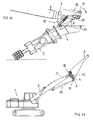
- the figure 1represents a machine 1 such as a hydraulic excavator, having an arrow 2.
- a coupler 3intended to be coupled to an interface 4 itself mounted on a tool 5, in order to allow the coupling of this tool to the arrow.
- the tool 5 illustrated on the figure 1comprises an arm 6 and a bucket 7, but the invention applies to the coupling of other tools, such as hammers, hydraulic clamps, etc.
- the coupler 3, illustrated more particularly on the Figures 3 and 4comprises, substantially in its central part, a bearing 8 of axis 9 for mounting the coupler 3 to the free end of the boom 2 pivotally about the axis 9.
- the coupler 3comprises a bearing 10 of axis 11 substantially parallel to the axis 9, intended to cooperate with a cylinder 12 mounted on the arrow 2, to enable the pivoting of the coupler 3 about the axis 9.
- the coupler 3comprises two lateral hooks 13.
- the axes 9, 11are substantially horizontal and orthogonal to the arrow 2. It is with respect to these axes that the terms "transverse” and “lateral” are used.
- the median longitudinal plane of the machine 1 and the coupler 3is also defined as being their vertical plane of symmetry, orthogonal to the axes 9, 11.
- the hooks 13are intended to receive the lateral parts of a bar 14 connected to the tool 5, the bar 14 can either be directly attached to the tool 5 ( figure 1 ) be part of the interface 4 ( Figures 6 and 7 ).
- each hook 13has substantially the shape of a U having first and second legs 15, 16 and a bottom 17.
- the first leg 15is located closer to the axis 9 than the second leg 16 and is more long as this last.
- the branches 15, 16have at their end opposite the bottom 17 an inlet surface 18, 19 in the form of a circular arc centered substantially on the pivot axis 9 of the coupler 3.
- the input surfaces 18, 19are angularly offset from one another by an angle ⁇ of the order of 15 to 25 °, the input surface 18 of the first branch being further away from the bottom 17 than the input surface 19 of the second limb 16.
- first leg 15may comprise at its free end a bearing surface 23 curved towards the inside of the hook 13.
- each hook 13substantially has a semicylindrical profile with axis 20 and forms the support surface of the bar 14 in the coupled position of the coupler 3 and the interface 4.
- the bottom 17 of the hook 13is connected to the surfaces of the hook 13. 18, 19 by two connecting surfaces 21, 22 substantially flat and tangent to said bottom 17.
- the connecting surfaces 21, 22are inclined up and down from the opening of the hook 13 towards the bottom 17, during the steps leading to the coupling of the coupler 3 and the interface 4.
- each hook 13When the coupler 3 is seen from the side (see figures 1 and 6 ), if a line is drawn between the axis 11 of the bearing 10 and the axis 20 of the bottom 17, the opening of each hook 13 is directed towards the line containing the pivot axis 9 of the coupler 3 In addition, in the embodiment shown, the branches 15, 16 of each hook 13 extend generally perpendicularly to this line.
- the hooks 13form two housing receiving an end portion of the bar 14, as illustrated in particular on the figure 4 .
- Each housingis delimited by the bottom 17 of the hook 13, as well as the branches 15, 16, which are connected and closed laterally by a substantially longitudinal wall 24.
- the receiving housing of the bar 14is also provided with openings for the entry of said bar into the housing.
- Orifices 27are formed in the first and second branches 15, 16. Their function will be indicated later.
- each branch 15, 16has a substantially flat portion 28 and parallel to the median longitudinal plane of the coupler 3, here substantially in the form of a ring ( Figures 3 and 4 ), extended by an inclined portion 29 towards said median longitudinal plane when approaching the flat portion 28.
- the coupler 3also comprises, in addition to the hooks 13, a coupling zone situated close to the bearing 10, designed to cooperate with a coupling zone formed on the interface 4.
- the coupling zone of the coupler 3forms a cavity 30, open opposite the hooks 13, and substantially parallelepiped shape.
- each hook 13is directed towards the outside of the coupling device comprising the coupler 3 and the interface 4.
- each hook 13is open opposite the zone coupling of the coupler 3.
- the opening of each hook 13is directed towards the arrow 2, at least during the gripping phase of a tool 5 placed on the ground, which allows the operator to benefit from excellent visibility for the movements to be performed during this phase.
- the coupling zone of the interface 4forms a projecting portion 31 able to be engaged in the cavity 30 of the coupler 3 ( figure 6 ), and therefore preferably has a shape complementary to that of said cavity 30.
- the projecting portion 31 and the cavity 30comprise longitudinally-opening orifices, respectively 32, 33, which are aligned in the coupled position of the coupler 3 and the interface 4.
- the interface 4also comprises a bar 14 of axis 34 extending transversely away from the projecting portion 31.
- the bar 14comprises a cylindrical rod 25 whose end portions project laterally from the interface 4, so as to It can be engaged in the hooks 13.
- Each of these extreme lateral partsis capped with a sleeve 35 having a cylindrical wall 36 having on one side a bottom 37 adjacent to the corresponding end of the cylindrical rod 25 and the other side an annular flange 38 bearing against the lateral face of the interface 4.
- the sleeves 35are fixed to the cylindrical rod 25, for example by means of screws 39.
- each sleeve 35further has, on its cylindrical wall 36, a flat surface 40 arranged to be substantially orthogonal to the connecting surfaces 21, 22 of the hooks 13 when the bar 14 is housed in the hooks 13.
- the displacement direction 43is generally perpendicular to the branches 15, 16 of the hook 13, as illustrated in FIG. figure 5 .
- the bolt 41has a bearing face 44 which is inclined relative to this direction 43 of the same angle as the flat surface 40 formed on the sleeve 35. This inclination is provided so that when the bolt 41 is moved in the direction 43 to its position locking, the clearance between the bolt 41 and the sleeve 35 decreases. In the locking position, the bolt 41 plates the sleeve 35 against the bottom 17 of the hook 13, thus ensuring effective maintenance.
- the bolt 45has a bearing face 48 inclined relative to the direction of displacement 47, as illustrated in FIGS. Figures 11 to 13 , the corresponding bearing face 49 of the interface 4, intended to come into contact with the bearing face 48 of the bolt 45, being inclined at the same angle with respect to this direction 47.
- This inclinationis intended so that when the bolt 45 is moved in the direction 47 to its locking position, the clearance j between the bolt 45 and the interface 4 decreases.
- the bolt 45plates the end face 50 of the projecting portion 31 of the interface 4 against the bottom 51 of the cavity 30 of the coupler 3, thus ensuring effective maintenance.
- each hook 13rotates around the corresponding sleeve 35, being guided by the input surface 18 of the first branch 15, until the second branch 16 passes under the sheath 35 and thus allows the lifting thereof.
- the figure 9corresponds to the beginning of the lifting of the tool 5 by the arrow 2, especially through the input surface 19 of the second branch 16 and the connecting surface 22.
- the figure 10shows the tool 5 partially detached from the ground and the sleeves 35 completely in place in the hooks 13.
- the locking processcan begin, as shown on the Figures 11 to 13 for the second locking means (the operation for the first locking means being identical).
- the actuator 46causes translation of the bolt 45 initially retracted according to its direction of movement 47.
- the bearing faces 48, 49 respectively of the bolt 45 and the coupler 3come closer because of their inclination with respect to the direction 47, the clearance j gradually decreasing with the advance of the bolt 45.
- the interface 4is immobilized against the coupler 3 by the cooperation between the surfaces 50, 51 on the one hand and 48, 49 on the other hand.
- the actuator 46provides a constant hydraulic action in the locking direction, the maintenance of the interface 4 to the coupler 3 is thus completely guaranteed.
- the device according to the inventionallows a recovery of the most frequent and the most important efforts developed by the piston side of the cylinder 12 and the reactions of the tool to the ground by surfaces (17, 36) and (50, 51) belonging to the structure of the coupler and the interface respectively, hooks 13 and bar 14, and cavity 30 and projecting portion 31.
- the reliability of the device and its evolution over timeis thus increased.
- the figure 14represents the machine 1 in the first installation phase of the tool 5 (here an arm 6).
- the arm 6is substantially brought into contact with the ground by action on the jacks of the arms of the machine 1.
- the bolts 41, 45are in locking position, and the machine is at a distance d1 from a ground mark. In this position, the bolts 41, 45 can be moved to their release position without risk of falling of the tool, the latter being in contact with the hooks 13 of the coupler 3 via the interface 4.
- the arm 6is moved by action on the jacks of the machine 1 and forward movement of the machine 1, until it comes into complete contact with the ground ( figure 15 ).
- the locking meansare in the release position, and the rotation of the interface 4 relative to the coupler 3 has taken place.
- the machine 1is at a distance d2 less than d1 from a ground mark.
- the arm 6is completely released from the coupler 3 and deposited on the ground, by acting on the jacks of the machine 1 ( figure 16 ).
- the machine 1is at a distance d3 less than d2 from a ground mark.
- the figure 17illustrates a variant in which the jack 12 actuating the coupler 3 is placed under the arrow 2 and not above it as is the case on the Figures 1 to 16 .
- This arrangementis particularly suitable for tools 5 used for working at height.
- the hooks 13are located in the upper part of the coupler 3 (the attachment device being similar to that described above, but arranged symmetrically with respect to a horizontal plane).
- the inventionprovides a decisive improvement to the prior art, providing a coupling device that allows the rapid replacement of a tool by another on the boom of a machine. Due to the particular orientation of the hooks, this replacement is very easy because it is performed by pivoting the coupler in one direction. The orientation of the opening of the hooks towards the machine also allows the operator to benefit from a very good visibility.
- the contact surfaces between the interface 4 and the coupler 3are arranged in such a way that they directly absorb the greatest forces resulting from the jack 12. Conversely, the smaller forces resulting from the jack 12 are taken up by the system. locking. On the contrary, in the prior art, it is the locking system, that is to say a movable part, which took up the maximum forces, which is not optimal mechanically.
Landscapes
- Engineering & Computer Science (AREA)
- Mechanical Engineering (AREA)
- Mining & Mineral Resources (AREA)
- Civil Engineering (AREA)
- General Engineering & Computer Science (AREA)
- Structural Engineering (AREA)
- Shovels (AREA)
- Earth Drilling (AREA)
Abstract
Description
Translated fromFrenchLa présente invention concerne un dispositif de couplage d'un outil à l'extrémité de la flèche d'un engin tel qu'une pelle hydraulique.The present invention relates to a coupling device of a tool at the end of the boom of a machine such as a hydraulic shovel.
Le document
Le document
- deux crochets écartés latéralement, destinés à recevoir une barre liée à l'outil ;
- des premiers moyens de verrouillage associés aux crochets, pouvant être déplacés par des premiers moyens d'actionnement entre une position de verrouillage dans laquelle la barre est retenue dans les crochets et une position de libération dans laquelle la barre peut être déplacée hors des crochets ;
- une zone de couplage située à distance des crochets et destinée à coopérer avec une zone de couplage ménagée sur l'interface ;
- des seconds moyens de verrouillage situés dans la zone de couplage, pouvant être déplacés par des seconds moyens d'actionnement entre une position de verrouillage dans laquelle les zones de couplage sont maintenues en position accouplée, et une position de libération dans laquelle les zones de couplage peuvent être désaccouplées.
- two hooks laterally spaced, for receiving a bar connected to the tool;
- first locking means associated with the hooks, movable by first actuating means between a locking position in which the bar is retained in the hooks and a release position in which the bar can be moved out of the hooks;
- a coupling zone located at a distance from the hooks and intended to cooperate with a coupling zone formed on the interface;
- second locking means located in the coupling zone, displaceable by second actuating means between a locking position in which the coupling zones are held in the coupled position, and a release position in which the coupling zones can be uncoupled.
Toutefois, ce dispositif de couplage présente un certain nombre d'inconvénients.However, this coupling device has a number of disadvantages.
D'une part, du fait que les crochets sont ouverts vers l'intérieur du dispositif, la préhension de l'outil posé au sol en vue de son accouplement impose un mouvement alternatif du coupleur. En effet, dans un premier temps, le coupleur doit être rapproché de la flèche pour que les crochets saisissent la barre liée à l'outil puis, dans un deuxième temps, le coupleur doit être éloigné de la flèche pour se rapprocher de l'interface et permettre le verrouillage. Pour l'opérateur, ce mouvement alternatif est relativement complexe et long à exécuter. Ceci est accentué par le fait que la visibilité de l'opérateur lors de cette opération est réduite, car le coupleur cache la zone des crochets et du système de verrouillage. De plus, le risque de perdre l'outil dans la phase de verrouillage est important, car l'éloignement du coupleur par rapport à la flèche peut conduire à la sortie de la barre de l'outil hors des crochets.On the one hand, because the hooks are open towards the inside of the device, the gripping of the tool placed on the ground with a view to its coupling imposes an alternating movement of the coupler. In fact, initially, the coupler must be brought closer to the arrow so that the hooks grip the bar connected to the tool then, in a second step, the coupler must be moved away from the arrow to get closer to the interface and allow locking. For the operator, this reciprocating motion is relatively complex and time consuming to execute. This is accentuated by the fact that the visibility of the operator during this operation is reduced because the coupler hides the area of the hooks and the locking system. In addition, the risk of losing the tool in the locking phase is important because the distance of the coupler relative to the arrow can lead to the output of the bar of the tool out of the hooks.
D'autre part, d'un point de vue mécanique, la reprise des réactions principales se fait sur le système de verrouillage, ce qui entraîne l'apparition prématurée de jeux et de matages.On the other hand, from a mechanical point of view, the recovery of the main reactions is done on the locking system, resulting in the premature appearance of games and matings.
La présente invention vise à remédier aux inconvénients mentionnés ci-dessus.The present invention aims to overcome the disadvantages mentioned above.
A cet effet, et selon un premier aspect, l'invention concerne un dispositif de couplage du type précité, dans lequel l'ouverture des crochets est dirigée vers l'extérieur du dispositif, à l'opposé desdites zones de couplage, en position accouplée du coupleur et de l'interface. Les crochets sont agencés de sorte que le pivotement du coupleur par rapport à la flèche autour de son axe de pivotement et dans un sens donné puisse provoquer l'engagement de la barre liée à l'outil dans lesdits crochets et le rapprochement des zones de couplage par rotation autour de l'axe de la barre de l'interface relativement au coupleur.For this purpose, and according to a first aspect, the invention relates to a coupling device of the aforementioned type, in which the opening of the hooks is directed towards the outside of the device, opposite said coupling zones, in the coupled position. coupler and interface. The hooks are arranged so that the pivoting of the coupler relative to the arrow about its pivot axis and in a given direction can cause the engagement of the bar connected to the tool in said hooks and the approximation of the coupling zones. by rotation about the axis of the interface bar relative to the coupler.
De plus, selon l'invention, la zone de couplage du coupleur forme une cavité et la zone de couplage de l'interface forme une partie en saillie apte à être engagée dans ladite cavité, la partie en saillie et la cavité présentant des orifices traversants alignés en position accouplée, dans lesquels est apte à être inséré au moins un pêne appartenant aux seconds moyens de verrouillage du coupleur, le pêne étant agencé pour plaquer une face extrême de la partie en saillie de l'interface contre le fond de la cavité du coupleur en position de verrouillage.In addition, according to the invention, the coupling zone of the coupler forms a cavity and the coupling zone of the interface forms a protruding portion adapted to be engaged in said cavity, the protruding portion and the cavity having through orifices. aligned in the coupled position, in which is inserted at least one bolt belonging to the second locking means of the coupler, the bolt being arranged to press an end face of the projecting portion of the interface against the bottom of the cavity of the coupler in locking position.
Ainsi, grâce à la disposition de l'ouverture du crochet, l'opération de couplage de l'interface et du coupleur ne nécessite pas un mouvement alternatif et ne comporte pas de risque de perte de l'outil. En effet, « l'enroulement » des crochets autour de la barre entraîne le déplacement relatif de l'interface et du coupleur vers la position accouplée.Thus, thanks to the arrangement of the opening of the hook, the coupling operation of the interface and the coupler does not require reciprocating movement and does not involve any risk of loss of the tool. Indeed, "winding" of the hooks around the bar causes the relative movement of the interface and the coupler to the coupled position.
En outre, la configuration selon l'invention, dans laquelle le couplage est obtenu d'une part par un ensemble crochets - barres et d'autre part par un ensemble de structure différente, à savoir partie en saillie - cavité, présente plusieurs avantages :
- possibilité d'adaptation à différentes géométries, quel que soit l'écartement entre les deux axes prévus d'origine sur l'outil ou le bras (par exemple) initialement prévus pour se raccorder directement à la flèche, les positions de la partie en saillie et de la cavité étant adaptées à une gamme prédéterminé de plusieurs machines sélectionnées. II est à noter que le coupleur est monté à l'extrémité de la flèche, et donc l'interface est montée à l'extrémité du bras portant le godet, et non directement sur le godet ;
- en position montée, le maintien efficace de l'outil par rapport à la flèche et la reprise des efforts sont assurés en partie par les premiers moyens de verrouillage associés aux crochets, et en partie par la coopération entre la face extrême de la partie en saillie de l'interface et le fond de la cavité du coupleur. Ainsi, au niveau des crochets, on assure bien entendu une préhension mais également un maintien et un verrouillage. La reprise d'efforts est obtenue par une conception simple, et est d'autant plus efficace que les crochets sont écartés latéralement l'un de l'autre de façon relativement importante. Par ailleurs, au niveau de la cavité, on réalise une transmission d'efforts par le contact entre deux surfaces simples, par exemple sensiblement planes, évitant ainsi des difficultés de positionnement relatif.
- possibility of adaptation to different geometries, whatever the spacing between the two axes originally provided on the tool or the arm (for example) initially intended to be connected directly to the boom, the positions of the projecting part and the cavity being adapted to a predetermined range of several selected machines. It should be noted that coupler is mounted at the end of the boom, and thus the interface is mounted at the end of the arm carrying the bucket, and not directly on the bucket;
- in the mounted position, effective maintenance of the tool relative to the boom and the recovery of forces are provided in part by the first locking means associated with the hooks, and partly by the cooperation between the end face of the projecting portion of the interface and the bottom of the coupler cavity. Thus, at the hooks, it ensures of course a grip but also a maintenance and locking. The recovery efforts is obtained by a simple design, and is even more effective that the hooks are laterally spaced from each other relatively importantly. Furthermore, at the cavity, a transmission of forces is achieved by the contact between two simple surfaces, for example substantially flat, thus avoiding difficulties of relative positioning.
Selon une réalisation possible, chaque crochet présente sensiblement la forme d'un U dont chaque branche comprend une surface d'entrée en forme d'arc de cercle centré sensiblement sur l'axe de pivotement du coupleur, lesdites surfaces d'entrée étant décalées angulairement l'une par rapport à l'autre et destinées au guidage de la barre vers le fond du crochet lorsque le coupleur pivote par rapport à la flèche autour de son axe de pivotement. La surface supérieure située le plus en avant permet ainsi le positionnement initial du coupleur par rapport à l'outil puis son guidage, tandis que la surface inférieure située le plus en arrière permet, lorsque la barre repose sur elle, de soulever l'outil après pivotement du coupleur.According to a possible embodiment, each hook has substantially the shape of a U, each leg of which comprises an arcuate entrance surface centered substantially on the pivot axis of the coupler, said input surfaces being angularly offset. relative to one another and intended to guide the bar towards the bottom of the hook when the coupler pivots relative to the arrow about its pivot axis. The upper surface located foremost thus allows the initial positioning of the coupler relative to the tool and its guidance, while the lower rearmost surface allows, when the bar rests on it, to lift the tool after pivoting of the coupler.
La face latérale intérieure de chaque crochet peut comporter une première partie sensiblement plane et parallèle au plan longitudinal médian du coupleur, destinée à coopérer avec une face latérale de l'interface, prolongée par une deuxième partie inclinée vers ledit plan longitudinal médian lorsque l'on se rapproche de la première partie plane. Ceci permet de guider le mouvement d'engagement de la barre dans les crochets, ainsi que le centrage latéral de l'interface par rapport au coupleur. Cette géométrie est d'autant plus intéressante que l'opérateur ne dispose que de deux degrés de liberté en rotation (flèche et coupleur) pour réaliser la manoeuvre de couplage de l'outil à la flèche, et non plus trois (le troisième degré de liberté correspondant à la rotation du godet par rapport au bras dans le cas le plus usuel d'une attache rapide de godet fixée en bout de bras).The inner side face of each hook may comprise a first substantially flat portion and parallel to the median longitudinal plane of the coupler, intended to cooperate with a lateral face of the interface, extended by a second portion inclined towards said median longitudinal plane when one gets closer to the first flat part. This allows to guide the movement of engagement of the bar in the hooks, as well as the lateral centering of the interface relative to the coupler. This geometry is all the more interesting because the operator only has two degrees of freedom in rotation (boom and coupler) to perform the coupling operation of the tool to the arrow, and no longer three (the third degree of freedom corresponding to the rotation of the bucket with respect to the arm in the most usual case of a bucket quick coupler fixed at the end of the arm).
Les premiers moyens de verrouillage du coupleur peuvent comporter un pêne qui, en position de verrouillage, traverse le crochet de sorte à former un logement de retenue de la barre contre le fond du crochet.The first locking means of the coupler may comprise a bolt which, in the locking position, passes through the hook so as to form a retaining housing of the bar against the bottom of the hook.
Par ailleurs, les premiers et/ou les seconds moyens de verrouillage peuvent être mobiles en translation entre leur position de verrouillage et leur position de libération. Par rapport à des moyens de verrouillage mobiles en rotation, on obtient un système bien plus compact, nécessitant moins de pièces et un système de pilotage simplifié.Furthermore, the first and / or second locking means may be movable in translation between their locking position and their release position. Compared to locking means movable in rotation, a much more compact system is obtained, requiring fewer parts and a simplified control system.
Avantageusement, une face du pêne destinée à venir en contact avec l'interface ou la barre, en regard du coupleur, est inclinée par rapport à sa direction de déplacement, de telle sorte que le déplacement dudit pêne vers la position de verrouillage plaque une face de l'interface ou une face de la barre contre une face du coupleur. Grâce à cette structure, on peut rattraper le jeu existant entre les différentes pièces et obtenir un verrouillage satisfaisant.Advantageously, a face of the bolt intended to come into contact with the interface or the bar, opposite the coupler, is inclined with respect to its direction of displacement, so that the displacement of said bolt towards the locking position plates a face. of the interface or a face of the bar against a face of the coupler. Thanks to this structure, it is possible to make up the existing clearance between the different parts and to obtain a satisfactory locking.
Selon une réalisation possible, les extrémités de la barre, destinées à être engagées dans les crochets, sont entourées chacune par un fourreau, le fourreau pouvant présenter une surface plane destinée à coopérer avec la face inclinée du pêne des premiers moyens de verrouillage.According to one possible embodiment, the ends of the bar, intended to be engaged in the hooks, are each surrounded by a sleeve, the sleeve may have a flat surface intended to cooperate with the inclined face of the bolt of the first locking means.
Selon un deuxième aspect, l'invention concerne un engin tel qu'une pelle hydraulique, comprenant d'une part une flèche à l'extrémité de laquelle est monté un dispositif de couplage tel que précédemment décrit, l'axe de pivotement du coupleur étant situé sensiblement en partie centrale du coupleur, et d'autre part un vérin monté sur la flèche et relié à une première partie extrême du coupleur pour faire pivoter celui-ci par rapport à la flèche, les crochets étant ménagés à la deuxième partie extrême du coupleur.According to a second aspect, the invention relates to a machine such as a hydraulic excavator, comprising on the one hand an arrow at the end of which is mounted a coupling device as previously described, the pivot axis of the coupler being located substantially in the central portion of the coupler, and secondly a cylinder mounted on the boom and connected to a first end portion of the coupler to pivot it relative to the arrow, the hooks being formed at the second end portion of the coupler.
Avantageusement, l'ouverture des crochets est dirigée vers la flèche, ce qui permet d'obtenir une très bonne visibilité pour l'opérateur devant réaliser la préhension de l'outil.Advantageously, the opening of the hooks is directed towards the arrow, which makes it possible to obtain very good visibility for the operator having to grip the tool.
On décrit à présent, à titre d'exemples non limitatifs, plusieurs modes de réalisation possibles de l'invention, en référence aux figures annexées :
- La
figure 1 est une vue latérale d'un engin comportant un dispositif de couplage selon l'invention ; - La
figure 2 est une vue en perspective agrandie du dispositif de couplage, l'interface et le coupleur étant en position accouplée et les premiers moyens de verrouillage étant en position déverrouillée ; - La
figure 3 est une vue en perspective, de dessous, du coupleur, les premiers et les seconds moyens de verrouillage étant en position déverrouillée ; - La
figure 4 est une vue en perspective, de dessus, du coupleur accouplé à l'interface montée sur un outil, les premiers moyens de verrouillage étant dans une position intermédiaire ; - La
figure 5 est une vue partielle en section du coupleur et de l'interface, selon un plan vertical longitudinal passant par l'axe des premiers moyens de verrouillage ; - La
figure 6 est une vue latérale du dispositif de couplage, le coupleur étant vu en section selon un plan vertical longitudinal passant par l'axe des seconds moyens de verrouillage, l'interface et le coupleur étant en position accouplée et les seconds moyens de verrouillage étant en position verrouillée ; - La
figure 7 est une vue en coupe de l'interface, selon un plan vertical passant par l'axe de la barre liée à l'interface ; - Les
figures 8 à 10 illustrent différentes étapes du montage de l'outil sur la flèche de l'engin au moyen du dispositif selon l'invention ; - Les
figures 11 à 13 illustrent différentes étapes du verrouillage de l'interface et du coupleur au niveau des seconds moyens de verrouillage ; - Les
figures 14 à 16 illustrent différentes étapes de la pose sur le sol de l'outil monté sur la flèche de l'engin au moyen du dispositif selon l'invention ; et - La
figure 17 est une vue latérale d'un engin comportant un dispositif de couplage selon une variante de l'invention.
- The
figure 1 is a side view of a machine comprising a coupling device according to the invention; - The
figure 2 is an enlarged perspective view of the coupling device, the interface and the coupler being in the coupled position and the first locking means being in the unlocked position; - The
figure 3 is a perspective view, from below, of the coupler, the first and the second locking means being in the unlocked position; - The
figure 4 is a perspective view, from above, of the coupler coupled to the interface mounted on a tool, the first locking means being in an intermediate position; - The
figure 5 is a partial sectional view of the coupler and the interface, in a longitudinal vertical plane passing through the axis of the first locking means; - The
figure 6 is a side view of the coupling device, the coupler being seen in section along a longitudinal vertical plane passing through the axis of the second locking means, the interface and the coupler being in the coupled position and the second locking means being in position locked; - The
figure 7 is a sectional view of the interface, in a vertical plane passing through the axis of the bar connected to the interface; - The
Figures 8 to 10 illustrate different steps of mounting the tool on the boom of the machine by means of the device according to the invention; - The
Figures 11 to 13 illustrate different steps of locking the interface and the coupler at the second locking means; - The
Figures 14 to 16 illustrate different stages of laying on the ground of the tool mounted on the boom of the machine by means of the device according to the invention; and - The
figure 17 is a side view of a machine comprising a coupling device according to a variant of the invention.
La
Le coupleur 3, illustré plus particulièrement sur les
En position montée sur la flèche 2, les axes 9, 11 sont sensiblement horizontaux et orthogonaux à la flèche 2. C'est par rapport à ces axes que sont employés les termes « transversal » et « latéral ». On définit par ailleurs le plan longitudinal médian de l'engin 1 et du coupleur 3 comme étant leur plan vertical de symétrie, orthogonal aux axes 9, 11.In the mounted position on the
Les crochets 13 sont destinés à recevoir les parties latérales d'une barre 14 liée à l'outil 5, la barre 14 pouvant soit être directement fixée sur l'outil 5 (
Comme illustré sur la
Les branches 15, 16 comportent à leur partie extrême opposée au fond 17 une surface d'entrée 18, 19 en forme d'arc de cercle centré sensiblement sur l'axe 9 de pivotement du coupleur 3. Les surfaces d'entrée 18, 19 sont décalées angulairement l'une par rapport à l'autre d'un angle α de l'ordre de 15 à 25°, la surface d'entrée 18 de la première branche étant plus éloignée du fond 17 que la surface d'entrée 19 de la deuxième branche 16.The
En outre, la première branche 15 peut comporter à son extrémité libre une surface d'appui 23 incurvée vers l'intérieur du crochet 13.In addition, the
Le fond 17 de chaque crochet 13 présente sensiblement un profil hémicylindrique d'axe 20 et forme surface de support de la barre 14 en position accouplée du coupleur 3 et de l'interface 4. Le fond 17 du crochet 13 est relié aux surfaces d'entrée 18, 19 par deux surfaces de liaison 21, 22 sensiblement planes et tangentes audit fond 17. Avantageusement, les surfaces de liaison 21, 22 sont inclinées de haut en bas depuis l'ouverture du crochet 13 en direction du fond 17, lors des étapes conduisant à l'accouplement du coupleur 3 et de l'interface 4.The bottom 17 of each
Lorsque le coupleur 3 est vu de côté (voir
Les crochets 13 forment deux logements de réception d'une partie extrême de la barre 14, comme illustré notamment sur la
Des orifices 27 sont ménagés dans les première et deuxième branches 15, 16. Leur fonction sera indiquée plus loin.
La face latérale intérieure de chaque branche 15, 16 comporte une partie sensiblement plane 28 et parallèle au plan longitudinal médian du coupleur 3, ici sensiblement en forme de couronne (
Le coupleur 3 comprend également, en plus des crochets 13, une zone de couplage située à proximité du palier 10, destinée à coopérer avec une zone de couplage ménagée sur l'interface 4. La zone de couplage du coupleur 3 forme une cavité 30, ouverte à l'opposé des crochets 13, et de forme sensiblement parallélépipédique.The
Selon l'invention, l'ouverture de chaque crochet 13 est dirigée vers l'extérieur du dispositif de couplage comprenant le coupleur 3 et l'interface 4. En d'autres termes, chaque crochet 13 est ouvert à l'opposé de la zone de couplage ménagée sur le coupleur 3. Avantageusement, l'ouverture de chaque crochet 13 est dirigée vers la flèche 2, au moins pendant la phase de préhension d'un outil 5 posé au sol, ce qui permet à l'opérateur de bénéficier d'une excellente visibilité pour les mouvements à effectuer lors de cette phase.According to the invention, the opening of each
La zone de couplage de l'interface 4 forme une partie en saillie 31 apte à être engagée dans la cavité 30 du coupleur 3 (
L'interface 4 comprend également une barre 14 d'axe 34 s'étendant transversalement à distance de la partie en saillie 31. La barre 14 comprend une tige cylindrique 25 dont les parties extrêmes font saillie latéralement de l'interface 4, de façon à pouvoir être engagées dans les crochets 13. Chacune de ces parties extrêmes latérales est coiffée d'un fourreau 35 présentant une paroi cylindrique 36 présentant d'un côté un fond 37 adjacent à l'extrémité correspondante de la tige cylindrique 25 et de l'autre côté une collerette 38 annulaire prenant appui contre la face latérale de l'interface 4. Les fourreaux 35 sont fixés à la tige cylindrique 25, par exemple au moyen de vis 39.The
Les fourreaux 35 sont des pièces d'adaptation dont le diamètre extérieur est généralement identique pour une taille d'engins donnée, tandis que leur diamètre intérieur varie. Ainsi, le fourreau 35 adapte le diamètre de la tige cylindrique 25 imposé par l'outil au diamètre du fond 17 propre aux crochets 13. En outre, les arêtes des fourreaux 35 sont arrondies pour faciliter l'entrée de la barre 14 dans les crochets 13. Comme illustré sur les
On décrit à présent les moyens de verrouillage prévus sur le coupleur 3.The locking means provided on the
Des premiers moyens de verrouillage sont disposés latéralement et associés aux crochets 13 pour permettre le verrouillage de la barre 14 dans ces crochets 13. De chaque côté du coupleur 3, un pêne 41 est prévu pour être translaté par un actionneur 42 selon une direction de déplacement 43 globalement longitudinale, entre :
- une position de verrouillage dans laquelle le pêne 41
traverse le crochet 13 en étant engagé dans lesorifices 27 ménagés dans les première et deuxièmebranches crochet 13, ce qui permet de retenir labarre 14 entre le fond 17 des crochets 13 et ledit pêne 41 ; - et une position de libération, dans laquelle le pêne 41 est rétracté et n'obstrue plus l'ouverture des crochets 13, la
barre 14 pouvant donc être déplacée hors des crochets 13.
- a locking position in which the
bolt 41 passes through thehook 13 by being engaged in theorifices 27 formed in the first andsecond branches hook 13, which makes it possible to retain thebar 14 between the bottom 17 of thehooks 13 and saidbolt 41; - and a release position, in which the
bolt 41 is retracted and no longer closes the opening of thehooks 13, thebar 14 can therefore be moved out of thehooks 13.
La direction de déplacement 43 est globalement perpendiculaire aux branches 15, 16 du crochet 13, comme illustré sur la
Des seconds moyens de verrouillage (
- une position de verrouillage dans laquelle le pêne 45 est engagé dans les orifices 32, 33 ménagés dans la partie en saillie 31 de l'interface 4 et la cavité 30 du coupleur 3, ce qui permet de retenir l'interface 4 dans sa position accouplée au coupleur 3 ;
- et une position de libération, dans laquelle le pêne 45 est rétracté et n'obstrue plus la cavité 30, la partie en saillie 31 pouvant donc être déplacée hors de la cavité 30.
- a locking position in which the
bolt 45 is engaged in theorifices portion 31 of theinterface 4 and thecavity 30 of thecoupler 3, which makes it possible to retain theinterface 4 in its coupledposition coupler 3; - and a release position, in which the
bolt 45 is retracted and no longer closes thecavity 30, the projectingportion 31 can therefore be moved out of thecavity 30.
Le pêne 45 présente une face d'appui 48 inclinée par rapport à la direction de déplacement 47, comme illustré sur les
On décrit à présent les étapes du montage de l'outil 5 sur la flèche 2 de l'engin, en référence aux
Initialement (
Au fur et à mesure du pivotement du coupleur 3 autour de son axe 9, chaque crochet 13 tourne autour du fourreau 35 correspondant, en étant guidé par la surface d'entrée 18 de la première branche 15, jusqu'à ce que la deuxième branche 16 passe sous le fourreau 35 et permette donc le soulèvement de celui-ci. La
Ensuite, du fait de l'inclinaison des surfaces de liaison 21, 22 vers le bas, le mouvement ascendant de la flèche 2 (
L'engagement des fourreaux 35 dans les crochets 13 est facilité par la partie inclinée 29 et convergente de la face latérale intérieure des branches 15, 16 de ces crochets 13 et les arêtes arrondies des fourreaux 35. Lorsque les fourreaux 35 sont en place contre le fond 17 des crochets 13, la face latérale de chaque collerette 38 est en appui contre la partie sensiblement plane 28 de la face latérale intérieure de la branche 15, 16 du crochet 13 correspondant. En outre, il existe un jeu latéral entre le bord arrondi de chaque fourreau 35 et la paroi latérale 24 du crochet 13. Ces dispositions permettent d'assurer un excellent centrage de l'interface 4 par rapport au coupleur 3 (et donc ultérieurement de permettre la connexion hydraulique entre la flèche 2 et l'outil 5 par raccordement des conduits de fluide) et un blocage dans cette position.The engagement of the
La
On notera que le vérin 12 aura toujours été actionné dans le même sens dans toutes les phases de cette opération de préhension de l'outil 5, ce qui simplifie la conduite de l'engin.Note that the
Une fois l'interface 4 correctement positionnée contre le coupleur 3, le processus de verrouillage peut commencer, comme représenté sur les
Lorsque le pêne 45 est en position de verrouillage (
De la même manière, les fourreaux 35 sont immobilisés par rapport aux crochets 13.In the same way, the
Ainsi accouplé, le dispositif selon l'invention permet une reprise des efforts les plus fréquents et les plus importants développés par le côté piston du vérin 12 et les réactions de l'outil au sol par des surfaces (17, 36) et (50, 51) appartenant à la structure du coupleur et à l'interface respectivement, crochets 13 et barre 14, et cavité 30 et partie en saillie 31. La reprise des efforts les plus faibles développés par le côté tige du vérin 12 et les réactions de l'outil, transitant respectivement par les surfaces (40, 44) et (48, 49) respectivement aux premiers et seconds moyens de verrouillage (41, 45). La fiabilité du dispositif et son évolution dans le temps est ainsi augmentée.Thus coupled, the device according to the invention allows a recovery of the most frequent and the most important efforts developed by the piston side of the
Les étapes de la pose sur le sol de l'outil 5 monté sur la flèche 2 sont maintenant décrites en référence aux
La
Dans la deuxième phase de pose de l'outil, le bras 6 est déplacé par action sur les vérins de l'engin 1 et déplacement vers l'avant de l'engin 1, jusqu'à venir en contact complet avec le sol (
Enfin, le bras 6 est complètement dégagé du coupleur 3 et déposé au sol, par action sur les vérins de l'engin 1 (
La
Ainsi, l'invention apporte une amélioration déterminante à la technique antérieure, en fournissant un dispositif de couplage qui permet le remplacement rapide d'un outil par un autre sur la flèche d'un engin. Grâce à l'orientation particulière des crochets, ce remplacement est très aisé, car il s'effectue grâce à un pivotement du coupleur dans un seul sens. L'orientation de l'ouverture des crochets vers l'engin permet en outre à l'opérateur de bénéficier d'une très bonne visibilité.Thus, the invention provides a decisive improvement to the prior art, providing a coupling device that allows the rapid replacement of a tool by another on the boom of a machine. Due to the particular orientation of the hooks, this replacement is very easy because it is performed by pivoting the coupler in one direction. The orientation of the opening of the hooks towards the machine also allows the operator to benefit from a very good visibility.
Par ailleurs, les surfaces de contact entre l'interface 4 et le coupleur 3 sont disposées de telle manière qu'elles absorbent directement les plus grands efforts résultant du vérin 12. Inversement, les efforts plus petits résultant du vérin 12 sont repris par le système de verrouillage. Au contraire, dans l'art antérieur, c'est le système de verrouillage, c'est-à-dire une partie mobile, qui reprenait les efforts maximaux, ce qui n'est pas optimal mécaniquement.Furthermore, the contact surfaces between the
Claims (11)
- A coupling device for coupling a tool (5) to the end of the boom (2) of a vehicle such as a hydraulic shovel, comprising a coupler (3) mounted at the end of the boom (2) around a pivot axis (9), and an interface (4) mounted on the tool (5), the coupler (3) comprising:- two hooks (13) spaced laterally apart and intended to receive a bar (14) connected to the interface (4);- first locking means (41) associated with the hooks (13), which can be moved by first actuating means (42) between a locking position in which the bar (14) is retained in the hooks (13) and a released position in which the bar (14) can be moved outside the hooks (13);- a coupling area (30) situated away from the hooks (13) and intended to cooperate with the coupling area (31) formed on the interface (4);- second locking means (45) situated in the coupling area, which can be moved by second actuating means (46) between a locking position in which the coupling areas are kept in the coupled position, and a released position in which the coupling areas can be uncoupled;characterized in that the opening of the hooks (13) is oriented toward the outside of the device, opposite said coupling areas (30, 31), in the coupled position of the coupler (3) and the interface (4), the hooks (13) being arranged so that the pivoting of the coupler (3) relative to the boom (2) around its pivot axis (9) and in a given position can cause the engagement of the bar (14) connected to the tool (5) in said hooks (13) and the approach of the coupling areas (30, 31) of the coupler (3) and the interface (4) by rotation around the axis (34) of the bar (14) of the interface (4) relative to the coupler (3), andin that the coupling area of the coupler (3) forms a cavity (30) and the coupling area of the interface (4) forms a protruding portion (31) capable of being engaged in said cavity (30), the protruding portion (31) and the cavity (30) having through orifices (32, 33) aligned in the coupled position, in which at least one bolt (45) belonging to the second locking means of the coupler (3) can be inserted, the bolt (45) being arranged to press an end surface (50) of the protruding portion (31) of the interface (4) against the bottom (51) of the cavity (30) of the coupler (3) in the locking position.
- The device according to claim 1,characterized in that each hook (13) is substantially in the shape of a U whereof each branch (15, 16) comprises an inlet surface (18, 19) in the shape of an arc of circle substantially centered on the pivot axis (9) of the coupler (3), said inlet surfaces (18, 19) being angularly offset relative to one another and intended to guide the bar (14) toward the bottom of the hook (13) when the coupler (3) pivots around its pivot axis (9) relative to the boom (2).
- The device according to claim 2,characterized in that the bottom (17) of each hook (13) substantially has a semi-cylindrical profile and forms a support surface for the bar (14) in the coupled position of the coupler (3) and the interface (4), the bottom (17) of the hook (13) being connected to the inlet surfaces (18, 19) by two connecting surfaces (21, 22) that are substantially flat and tangent to the bottom (17), the connecting surfaces (21, 22) being inclined from top to bottom from the opening of the hook (13) toward the bottom (17), during steps leading to the coupling of the coupler (3) and the interface (4).
- The device according to any one of claims 1 to 3,characterized in that the inner side surface of each hook (13) comprises a first substantially flat portion (28) parallel to the median longitudinal plane of the coupler (3), intended to cooperate with a side surface (38) of the interface (4), extended by a second inclined portion (29) toward said median longitudinal plane as one comes closer to the first flat portion (28).
- The device according to one of claims 1 to 4,characterized in that the first and/or second locking means (41, 45) are translationally mobile between their locking position and their released position.
- The device according to any one of claims 1 to 5,characterized in that the first locking means of the coupler (3) comprise a bolt (41) which, in the locking position, passes through the hook (13) so as to form a housing for keeping the bar (14) against the bottom (17) of the hook (13).
- The device according to any one of claims 1 to 6,characterized in that a surface (44, 48) of the bolt (41, 45) intended to come into contact with a surface (40, 49) of the interface (4) or the bar (14), opposite the coupler (3), is inclined relative to its direction of movement (43, 47), so that the movement of said bolt (41, 45) toward the locking position presses a surface (50) of the interface (4) or a surface (36) of the bar (14) against a surface (51, 17) of the coupler (3).
- The device according to any one of claims 1 to 7,characterized in that the bar (14) comprises a cylindrical rod whereof the lateral end portions intended to be engaged in the hooks (13) are each surrounded by a sheath (35).
- The device according to claims 7 and 8,characterized in that the sheath (35) has a flat surface (40) intended to cooperate with the inclined surface (44) of the bolt (41) of the first locking means.
- A vehicle such as a hydraulic shovel, comprising on the one hand the boom (2) at the end of which a coupling device according to one of claims 1 to 9 is mounted, the pivot axis (9) of the coupler (3) being situated substantially in the central portion of the coupler (3), and on the other hand a cylinder (12) mounted on the boom (2) and connected to a first end portion of the coupler (3) to make the latter pivot relative to the boom (2), the hooks (13) being formed at the second end portion of the coupler (3).
- The vehicle according to claim 10,characterized in that the opening of the hooks (13) is oriented toward the boom (2).
Applications Claiming Priority (2)
| Application Number | Priority Date | Filing Date | Title |
|---|---|---|---|
| FR0603558AFR2900169B1 (en) | 2006-04-21 | 2006-04-21 | DEVICE FOR COUPLING A TOOL TO THE ARROW OF A VEHICLE SUCH AS A HYDRAULIC EXCAVATOR |
| PCT/FR2007/000656WO2007122320A1 (en) | 2006-04-21 | 2007-04-19 | Device four coupling a tool with the boom of a machine such as a hydraulic shovel |
Publications (2)
| Publication Number | Publication Date |
|---|---|
| EP2010720A1 EP2010720A1 (en) | 2009-01-07 |
| EP2010720B1true EP2010720B1 (en) | 2012-02-15 |
Family
ID=37487586
Family Applications (1)
| Application Number | Title | Priority Date | Filing Date |
|---|---|---|---|
| EP07731320AActiveEP2010720B1 (en) | 2006-04-21 | 2007-04-19 | Device four coupling a tool with the boom of a machine such as a hydraulic shovel |
Country Status (5)
| Country | Link |
|---|---|
| EP (1) | EP2010720B1 (en) |
| AT (1) | ATE545739T1 (en) |
| ES (1) | ES2381284T3 (en) |
| FR (1) | FR2900169B1 (en) |
| WO (1) | WO2007122320A1 (en) |
Families Citing this family (1)
| Publication number | Priority date | Publication date | Assignee | Title |
|---|---|---|---|---|
| GB2557934B (en) | 2016-12-16 | 2021-10-06 | Bamford Excavators Ltd | Arm assembly |
Family Cites Families (5)
| Publication number | Priority date | Publication date | Assignee | Title |
|---|---|---|---|---|
| US6428265B1 (en)* | 2000-10-30 | 2002-08-06 | Gilmore Industries, Inc. | Power coupling mounting for a quick-disconnect coupling on a heavy-duty machine |
| US6902346B2 (en)* | 2002-03-15 | 2005-06-07 | Hendrix Manufacturing, Ltd. | Hydraulic coupler |
| AU2003249360A1 (en)* | 2002-06-24 | 2004-01-06 | Jrb Company, Inc. | Arm assembly for excavation apparatus and method of using same |
| WO2004016863A1 (en)* | 2002-08-16 | 2004-02-26 | Simon Robert Ward | A connector |
| FR2854909B1 (en)* | 2003-05-13 | 2006-08-04 | Const Du Beaujolais Atel | DEVICE FOR COUPLING A TOOL AT THE END OF THE ARROW OF A GEAR, SUCH AS A HYDRAULIC EXCAVATOR |
- 2006
- 2006-04-21FRFR0603558Apatent/FR2900169B1/ennot_activeExpired - Fee Related
- 2007
- 2007-04-19ESES07731320Tpatent/ES2381284T3/enactiveActive
- 2007-04-19ATAT07731320Tpatent/ATE545739T1/enactive
- 2007-04-19EPEP07731320Apatent/EP2010720B1/enactiveActive
- 2007-04-19WOPCT/FR2007/000656patent/WO2007122320A1/enactiveApplication Filing
Also Published As
| Publication number | Publication date |
|---|---|
| EP2010720A1 (en) | 2009-01-07 |
| FR2900169B1 (en) | 2010-04-16 |
| WO2007122320A1 (en) | 2007-11-01 |
| ES2381284T3 (en) | 2012-05-24 |
| FR2900169A1 (en) | 2007-10-26 |
| ATE545739T1 (en) | 2012-03-15 |
Similar Documents
| Publication | Publication Date | Title |
|---|---|---|
| EP0438931B1 (en) | Device for connecting a bucket, or the like, to the boom end of a loader | |
| EP1533470A1 (en) | Drilling and bolting head for a bolting machine | |
| EP2280210B1 (en) | Branching assembly for a fluid transport pipe | |
| FR2611371A1 (en) | SYSTEM FOR DEPLOYING AND REMOVING AN OBSTACLE CROSSING WORK FROM A VEHICLE SUCH AS AN ENGINEERED ENGINE | |
| EP2010720B1 (en) | Device four coupling a tool with the boom of a machine such as a hydraulic shovel | |
| EP1470012B1 (en) | Rear boot hood for an open-top vehicle with a folding roof | |
| FR2910082A1 (en) | HYDRAULIC LOCKING DEVICE FOR LIFT ARMS | |
| EP0490798B1 (en) | Crane, especially for handling | |
| WO2020240120A1 (en) | Device for coupling two shafts, and hitching device provided with such a coupling device | |
| EP0704577B1 (en) | Quick-coupling for connecting implements to an excavator | |
| EP0378034B1 (en) | Rocking device for a loading platform | |
| EP3815969B1 (en) | Sewer-cleaning vehicle comprising an optimised storage tank | |
| FR2701047A1 (en) | Universal connection system for securing an accessory, in particular a bucket or bucket, to the articulated arm of a public works machine. | |
| FR2923756A1 (en) | Lockable and unlockable pivoting assembly e.g. front pivoting assembly, for bonnet in convertible vehicle, has hook mounted on base, and wall carried by male element of casing such that locking device releasably locks casing and base | |
| CA2364936A1 (en) | Grappling device and assembly for transforming an excavator's telescoping arm into an excavation and grappling arm | |
| EP3569774B1 (en) | Excavating machine comprising a steering tube that enables the rotation of the chassis | |
| EP1477615A1 (en) | A device for coupling an implement to the final end of a working arm of a machine, like a hydraulic excavator. | |
| EP4060124B1 (en) | Assembly for secure coupling of a tool for a work arm of a public works vehicle with improved operation | |
| FR2694316A1 (en) | Loader-excavator-elevator vehicle implement - has arm at free end of shaft and tool mounted on arm | |
| EP4086137B1 (en) | Tool for moving a coupling of a railway vehicle, associated assembly and method of use | |
| EP3012219A1 (en) | Earthworking device that can be adapted to the deck of a telescopic truck | |
| EP1449805B1 (en) | Gripper for lifting device | |
| FR2988409A1 (en) | Excavation bucket for use during supporting e.g. cast wall, in ground, has actuation unit swiveling cups and including arms connected to cups, where arms are movable with respect to frame, and cross each other so as to form X-shape | |
| EP2110481A1 (en) | Device for tilting a tool and, in particular a bucket of a construction machine | |
| EP1475481A1 (en) | Tool quick coupler for excavators |
Legal Events
| Date | Code | Title | Description |
|---|---|---|---|
| PUAI | Public reference made under article 153(3) epc to a published international application that has entered the european phase | Free format text:ORIGINAL CODE: 0009012 | |
| 17P | Request for examination filed | Effective date:20081003 | |
| AK | Designated contracting states | Kind code of ref document:A1 Designated state(s):AT BE BG CH CY CZ DE DK EE ES FI FR GB GR HU IE IS IT LI LT LU LV MC MT NL PL PT RO SE SI SK TR | |
| AX | Request for extension of the european patent | Extension state:AL BA HR MK RS | |
| RIN1 | Information on inventor provided before grant (corrected) | Inventor name:COUDERT, REMI Inventor name:SIEFFERT, RENE Inventor name:JANDARD, PHILIPPE Inventor name:MORIN, SERGE | |
| 17Q | First examination report despatched | Effective date:20091210 | |
| GRAP | Despatch of communication of intention to grant a patent | Free format text:ORIGINAL CODE: EPIDOSNIGR1 | |
| DAX | Request for extension of the european patent (deleted) | ||
| GRAS | Grant fee paid | Free format text:ORIGINAL CODE: EPIDOSNIGR3 | |
| GRAA | (expected) grant | Free format text:ORIGINAL CODE: 0009210 | |
| AK | Designated contracting states | Kind code of ref document:B1 Designated state(s):AT BE BG CH CY CZ DE DK EE ES FI FR GB GR HU IE IS IT LI LT LU LV MC MT NL PL PT RO SE SI SK TR | |
| REG | Reference to a national code | Ref country code:CH Ref legal event code:EP Ref country code:GB Ref legal event code:FG4D Free format text:NOT ENGLISH | |
| REG | Reference to a national code | Ref country code:IE Ref legal event code:FG4D Free format text:LANGUAGE OF EP DOCUMENT: FRENCH | |
| REG | Reference to a national code | Ref country code:AT Ref legal event code:REF Ref document number:545739 Country of ref document:AT Kind code of ref document:T Effective date:20120315 | |
| REG | Reference to a national code | Ref country code:DE Ref legal event code:R096 Ref document number:602007020704 Country of ref document:DE Effective date:20120412 | |
| RAP2 | Party data changed (patent owner data changed or rights of a patent transferred) | Owner name:ATELIERS DE CONSTRUCTIONS DU BEAUJOLAIS Owner name:MORIN SAS | |
| REG | Reference to a national code | Ref country code:ES Ref legal event code:FG2A Ref document number:2381284 Country of ref document:ES Kind code of ref document:T3 Effective date:20120524 | |
| REG | Reference to a national code | Ref country code:NL Ref legal event code:T3 | |
| LTIE | Lt: invalidation of european patent or patent extension | Effective date:20120215 | |
| PG25 | Lapsed in a contracting state [announced via postgrant information from national office to epo] | Ref country code:LT Free format text:LAPSE BECAUSE OF FAILURE TO SUBMIT A TRANSLATION OF THE DESCRIPTION OR TO PAY THE FEE WITHIN THE PRESCRIBED TIME-LIMIT Effective date:20120215 Ref country code:IS Free format text:LAPSE BECAUSE OF FAILURE TO SUBMIT A TRANSLATION OF THE DESCRIPTION OR TO PAY THE FEE WITHIN THE PRESCRIBED TIME-LIMIT Effective date:20120615 | |
| PG25 | Lapsed in a contracting state [announced via postgrant information from national office to epo] | Ref country code:GR Free format text:LAPSE BECAUSE OF FAILURE TO SUBMIT A TRANSLATION OF THE DESCRIPTION OR TO PAY THE FEE WITHIN THE PRESCRIBED TIME-LIMIT Effective date:20120516 Ref country code:LV Free format text:LAPSE BECAUSE OF FAILURE TO SUBMIT A TRANSLATION OF THE DESCRIPTION OR TO PAY THE FEE WITHIN THE PRESCRIBED TIME-LIMIT Effective date:20120215 Ref country code:PL Free format text:LAPSE BECAUSE OF FAILURE TO SUBMIT A TRANSLATION OF THE DESCRIPTION OR TO PAY THE FEE WITHIN THE PRESCRIBED TIME-LIMIT Effective date:20120215 Ref country code:FI Free format text:LAPSE BECAUSE OF FAILURE TO SUBMIT A TRANSLATION OF THE DESCRIPTION OR TO PAY THE FEE WITHIN THE PRESCRIBED TIME-LIMIT Effective date:20120215 Ref country code:PT Free format text:LAPSE BECAUSE OF FAILURE TO SUBMIT A TRANSLATION OF THE DESCRIPTION OR TO PAY THE FEE WITHIN THE PRESCRIBED TIME-LIMIT Effective date:20120615 | |
| REG | Reference to a national code | Ref country code:IE Ref legal event code:FD4D | |
| REG | Reference to a national code | Ref country code:AT Ref legal event code:MK05 Ref document number:545739 Country of ref document:AT Kind code of ref document:T Effective date:20120215 | |
| PG25 | Lapsed in a contracting state [announced via postgrant information from national office to epo] | Ref country code:CY Free format text:LAPSE BECAUSE OF FAILURE TO SUBMIT A TRANSLATION OF THE DESCRIPTION OR TO PAY THE FEE WITHIN THE PRESCRIBED TIME-LIMIT Effective date:20120215 | |
| PG25 | Lapsed in a contracting state [announced via postgrant information from national office to epo] | Ref country code:SE Free format text:LAPSE BECAUSE OF FAILURE TO SUBMIT A TRANSLATION OF THE DESCRIPTION OR TO PAY THE FEE WITHIN THE PRESCRIBED TIME-LIMIT Effective date:20120215 Ref country code:RO Free format text:LAPSE BECAUSE OF FAILURE TO SUBMIT A TRANSLATION OF THE DESCRIPTION OR TO PAY THE FEE WITHIN THE PRESCRIBED TIME-LIMIT Effective date:20120215 Ref country code:IE Free format text:LAPSE BECAUSE OF FAILURE TO SUBMIT A TRANSLATION OF THE DESCRIPTION OR TO PAY THE FEE WITHIN THE PRESCRIBED TIME-LIMIT Effective date:20120215 Ref country code:CZ Free format text:LAPSE BECAUSE OF FAILURE TO SUBMIT A TRANSLATION OF THE DESCRIPTION OR TO PAY THE FEE WITHIN THE PRESCRIBED TIME-LIMIT Effective date:20120215 Ref country code:EE Free format text:LAPSE BECAUSE OF FAILURE TO SUBMIT A TRANSLATION OF THE DESCRIPTION OR TO PAY THE FEE WITHIN THE PRESCRIBED TIME-LIMIT Effective date:20120215 Ref country code:DK Free format text:LAPSE BECAUSE OF FAILURE TO SUBMIT A TRANSLATION OF THE DESCRIPTION OR TO PAY THE FEE WITHIN THE PRESCRIBED TIME-LIMIT Effective date:20120215 Ref country code:SI Free format text:LAPSE BECAUSE OF FAILURE TO SUBMIT A TRANSLATION OF THE DESCRIPTION OR TO PAY THE FEE WITHIN THE PRESCRIBED TIME-LIMIT Effective date:20120215 | |
| PG25 | Lapsed in a contracting state [announced via postgrant information from national office to epo] | Ref country code:MC Free format text:LAPSE BECAUSE OF NON-PAYMENT OF DUE FEES Effective date:20120430 Ref country code:SK Free format text:LAPSE BECAUSE OF FAILURE TO SUBMIT A TRANSLATION OF THE DESCRIPTION OR TO PAY THE FEE WITHIN THE PRESCRIBED TIME-LIMIT Effective date:20120215 | |
| PLBE | No opposition filed within time limit | Free format text:ORIGINAL CODE: 0009261 | |
| STAA | Information on the status of an ep patent application or granted ep patent | Free format text:STATUS: NO OPPOSITION FILED WITHIN TIME LIMIT | |
| PGFP | Annual fee paid to national office [announced via postgrant information from national office to epo] | Ref country code:ES Payment date:20120416 Year of fee payment:6 | |
| 26N | No opposition filed | Effective date:20121116 | |
| PG25 | Lapsed in a contracting state [announced via postgrant information from national office to epo] | Ref country code:AT Free format text:LAPSE BECAUSE OF FAILURE TO SUBMIT A TRANSLATION OF THE DESCRIPTION OR TO PAY THE FEE WITHIN THE PRESCRIBED TIME-LIMIT Effective date:20120215 | |
| REG | Reference to a national code | Ref country code:DE Ref legal event code:R097 Ref document number:602007020704 Country of ref document:DE Effective date:20121116 | |
| PG25 | Lapsed in a contracting state [announced via postgrant information from national office to epo] | Ref country code:BG Free format text:LAPSE BECAUSE OF FAILURE TO SUBMIT A TRANSLATION OF THE DESCRIPTION OR TO PAY THE FEE WITHIN THE PRESCRIBED TIME-LIMIT Effective date:20120515 Ref country code:MT Free format text:LAPSE BECAUSE OF FAILURE TO SUBMIT A TRANSLATION OF THE DESCRIPTION OR TO PAY THE FEE WITHIN THE PRESCRIBED TIME-LIMIT Effective date:20120215 | |
| PGFP | Annual fee paid to national office [announced via postgrant information from national office to epo] | Ref country code:LU Payment date:20130517 Year of fee payment:7 | |
| PG25 | Lapsed in a contracting state [announced via postgrant information from national office to epo] | Ref country code:TR Free format text:LAPSE BECAUSE OF FAILURE TO SUBMIT A TRANSLATION OF THE DESCRIPTION OR TO PAY THE FEE WITHIN THE PRESCRIBED TIME-LIMIT Effective date:20120215 | |
| PGFP | Annual fee paid to national office [announced via postgrant information from national office to epo] | Ref country code:CH Payment date:20140331 Year of fee payment:8 | |
| PG25 | Lapsed in a contracting state [announced via postgrant information from national office to epo] | Ref country code:HU Free format text:LAPSE BECAUSE OF FAILURE TO SUBMIT A TRANSLATION OF THE DESCRIPTION OR TO PAY THE FEE WITHIN THE PRESCRIBED TIME-LIMIT Effective date:20070419 | |
| PGFP | Annual fee paid to national office [announced via postgrant information from national office to epo] | Ref country code:GB Payment date:20140403 Year of fee payment:8 | |
| PGFP | Annual fee paid to national office [announced via postgrant information from national office to epo] | Ref country code:NL Payment date:20140416 Year of fee payment:8 Ref country code:IT Payment date:20140417 Year of fee payment:8 Ref country code:DE Payment date:20140416 Year of fee payment:8 | |
| PGFP | Annual fee paid to national office [announced via postgrant information from national office to epo] | Ref country code:BE Payment date:20140429 Year of fee payment:8 | |
| PG25 | Lapsed in a contracting state [announced via postgrant information from national office to epo] | Ref country code:LU Free format text:LAPSE BECAUSE OF NON-PAYMENT OF DUE FEES Effective date:20140419 | |
| REG | Reference to a national code | Ref country code:DE Ref legal event code:R119 Ref document number:602007020704 Country of ref document:DE | |
| REG | Reference to a national code | Ref country code:CH Ref legal event code:PL | |
| GBPC | Gb: european patent ceased through non-payment of renewal fee | Effective date:20150419 | |
| REG | Reference to a national code | Ref country code:NL Ref legal event code:MM Effective date:20150501 | |
| PG25 | Lapsed in a contracting state [announced via postgrant information from national office to epo] | Ref country code:IT Free format text:LAPSE BECAUSE OF NON-PAYMENT OF DUE FEES Effective date:20150419 Ref country code:LI Free format text:LAPSE BECAUSE OF NON-PAYMENT OF DUE FEES Effective date:20150430 Ref country code:GB Free format text:LAPSE BECAUSE OF NON-PAYMENT OF DUE FEES Effective date:20150419 Ref country code:CH Free format text:LAPSE BECAUSE OF NON-PAYMENT OF DUE FEES Effective date:20150430 Ref country code:DE Free format text:LAPSE BECAUSE OF NON-PAYMENT OF DUE FEES Effective date:20151103 | |
| REG | Reference to a national code | Ref country code:FR Ref legal event code:PLFP Year of fee payment:10 | |
| PG25 | Lapsed in a contracting state [announced via postgrant information from national office to epo] | Ref country code:NL Free format text:LAPSE BECAUSE OF NON-PAYMENT OF DUE FEES Effective date:20150501 | |
| PG25 | Lapsed in a contracting state [announced via postgrant information from national office to epo] | Ref country code:ES Free format text:LAPSE BECAUSE OF NON-PAYMENT OF DUE FEES Effective date:20140420 | |
| REG | Reference to a national code | Ref country code:FR Ref legal event code:TP Owner name:ATELIERS DE CONSTRUCTIONS DU BEAUJOLAIS, FR Effective date:20160829 | |
| REG | Reference to a national code | Ref country code:FR Ref legal event code:PLFP Year of fee payment:11 | |
| PG25 | Lapsed in a contracting state [announced via postgrant information from national office to epo] | Ref country code:BE Free format text:LAPSE BECAUSE OF NON-PAYMENT OF DUE FEES Effective date:20150430 | |
| REG | Reference to a national code | Ref country code:FR Ref legal event code:PLFP Year of fee payment:12 | |
| PGFP | Annual fee paid to national office [announced via postgrant information from national office to epo] | Ref country code:FR Payment date:20250331 Year of fee payment:19 |