EP2009334A1 - Sectional valve or vacuum network with emergency intake - Google Patents
Sectional valve or vacuum network with emergency intakeDownload PDFInfo
- Publication number
- EP2009334A1 EP2009334A1EP07301148AEP07301148AEP2009334A1EP 2009334 A1EP2009334 A1EP 2009334A1EP 07301148 AEP07301148 AEP 07301148AEP 07301148 AEP07301148 AEP 07301148AEP 2009334 A1EP2009334 A1EP 2009334A1
- Authority
- EP
- European Patent Office
- Prior art keywords
- orifice
- passage
- vacuum
- control device
- valve
- Prior art date
- Legal status (The legal status is an assumption and is not a legal conclusion. Google has not performed a legal analysis and makes no representation as to the accuracy of the status listed.)
- Granted
Links
Images

Classifications
- F—MECHANICAL ENGINEERING; LIGHTING; HEATING; WEAPONS; BLASTING
- F16—ENGINEERING ELEMENTS AND UNITS; GENERAL MEASURES FOR PRODUCING AND MAINTAINING EFFECTIVE FUNCTIONING OF MACHINES OR INSTALLATIONS; THERMAL INSULATION IN GENERAL
- F16K—VALVES; TAPS; COCKS; ACTUATING-FLOATS; DEVICES FOR VENTING OR AERATING
- F16K5/00—Plug valves; Taps or cocks comprising only cut-off apparatus having at least one of the sealing faces shaped as a more or less complete surface of a solid of revolution, the opening and closing movement being predominantly rotary
- F16K5/06—Plug valves; Taps or cocks comprising only cut-off apparatus having at least one of the sealing faces shaped as a more or less complete surface of a solid of revolution, the opening and closing movement being predominantly rotary with plugs having spherical surfaces; Packings therefor
- F16K5/0663—Packings
- F16K5/0668—Single packings
- Y—GENERAL TAGGING OF NEW TECHNOLOGICAL DEVELOPMENTS; GENERAL TAGGING OF CROSS-SECTIONAL TECHNOLOGIES SPANNING OVER SEVERAL SECTIONS OF THE IPC; TECHNICAL SUBJECTS COVERED BY FORMER USPC CROSS-REFERENCE ART COLLECTIONS [XRACs] AND DIGESTS
- Y10—TECHNICAL SUBJECTS COVERED BY FORMER USPC
- Y10T—TECHNICAL SUBJECTS COVERED BY FORMER US CLASSIFICATION
- Y10T137/00—Fluid handling
- Y10T137/8593—Systems
- Y10T137/877—With flow control means for branched passages
- Y10T137/87885—Sectional block structure
- Y—GENERAL TAGGING OF NEW TECHNOLOGICAL DEVELOPMENTS; GENERAL TAGGING OF CROSS-SECTIONAL TECHNOLOGIES SPANNING OVER SEVERAL SECTIONS OF THE IPC; TECHNICAL SUBJECTS COVERED BY FORMER USPC CROSS-REFERENCE ART COLLECTIONS [XRACs] AND DIGESTS
- Y10—TECHNICAL SUBJECTS COVERED BY FORMER USPC
- Y10T—TECHNICAL SUBJECTS COVERED BY FORMER US CLASSIFICATION
- Y10T137/00—Fluid handling
- Y10T137/8593—Systems
- Y10T137/877—With flow control means for branched passages
- Y10T137/87909—Containing rotary valve
Definitions
- the inventionrelates to a valve that can be used on a pipeline or a network of vacuum pipes, in particular a network of vacuum pipes arranged in a hospital building.
- a vacuum pipe or a network of vacuum pipesthat is to say in depression, also browsing the various sites or rooms where the vacuum must be used, including treatment rooms, operating blocks, rooms ...
- the vacuumis used to suck different liquids, such as blood, phlegm, bodily fluids or the like, when caring for the sick.
- the vacuum networkcan not perform its normal role because it has a failure or an accidental and unpredictable interruption, for example because of damage to the fluid supply conduits, the control organs, regulating and interrupting the flow of the various fluids in circulation.
- a problemis to be able to easily and quickly connect such a mobile unit to the vacuum network of the hospital in case of failure of the vacuum network to avoid interruption of distribution of vacuum in the hospital or the like .
- the failure on the centralized vacuum networkmay be due for example to a problem on the vacuum unit or on the distribution network, for example caused by a rupture of external vacuum lines during maintenance or the like.
- an object of the inventionto provide a device for quickly and simply connect the vacuum network to a mobile vacuum unit or other emergency vacuum source.
- the valve 1 of the inventioncan be installed on a wall, essentially as a replacement for a possible shut-off valve of the conventional vacuum circuit possibly connected to a centralized suction installation comprising one or more vacuum pumps, preferably at least one 3 vacuum pumps, so that it can be connected to the vacuum socket provided on the rear wall of mobile functional unit, such as that described in the European patent application no. 07300937.5 by means of a suitable pipe, such as a flexible coupling whose opposite ends are threaded.
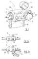
- the valve 1comprises two sub-parts or sub-units 12, 13 integral with each other, namely a first sub-unit 12 equipped with a control device 5, such as an all-ball valve. nothing manually controlled, and a second subunit 13 for connection to the functional unit 1 or the like.
- a manometer 11for controlling the depression in the valve body 1.
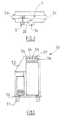
- valve body 1It is also possible to equip the valve body 1 with a pressure sensor arranged at the level of the third orifice 2c, for example a dedicated orifice situated under the valve may be provided for this sensor 30, as shown schematically in FIG. Figure 4 located at the downstream end of Annex 22.
- the subunit 13comprises a connection socket which comprises a threaded connection at its downstream end bearing the third orifice 2c normally closed by a closure plug 6 or the like which is itself threaded, said orifice 2c being situated towards a unit emergency function such as the one shown in Figure 5 .
- the subunits 12, 13are in fluid flow communication with each other so as to form an inner conduit which allows the vacuum to flow in the direction of the arrow F within the main passage 2 or, as the case may be,
- the valve of the inventionis designed and adapted to the management of the vacuum or vacuum supply continuity that the depression is due to a failure of the control unit. empty or the emergency functional unit.
- Fixing means 10such as a support flange or any similar fixing device, is provided to support the subunits 12, 13 of the valve body 1 and facilitate its installation on a wall.
- the actuatable member 5 of the control meanscan be actuated by an operator to close the main passage 2 on which is inserted the valve 1, as shown in Figure 3 .
- Vacuum networkis understood to mean a branching line or several channels connected or not to each other and within which vacuum prevails, ie a depression, namely a pressure below atmospheric pressure ( ⁇ 10 6 Pa). This vacuum is obtained by fluidly connecting the vacuum network to one or more vacuum pumps, as described in particular in the document EP-A-1026567 .
- the shutter 6is removed from the downstream end of the auxiliary passage 22 so as to release the third orifice 2c located at the downstream end of said auxiliary passage 22 which is then connected to a mobile spare functional unit comprising a pump.
- vacuumvia a pipe, such as a flexible conduit, which then ensures the maintenance vacuum vacuum network since vacuum suction, that is to say the implementation of depression of the valve body 1 and the network on which is mounted the valve of the invention, is then through the vacuum pump located in the mobile unit emergency.
- the Figure 4is an exploded view of the valve of the Figure 1 where it can be seen that the valve body 1 is formed of the two subunits 12, 13 or blocks which become solid with each other, for example by screwing to one another or via any other fixing means.
- the first subunit 12comprises the portion of the main passage 2 comprising the downstream end at which the second orifice 2b is located, that is to say the vacuum outlet if it is considered that the vacuum passes through the valve body 1 in the direction of the arrow F of the figure 1 , and the control device operable by the operator.
- control deviceis preferably an all-or-nothing ball valve in which the actuation in rotation of the rotary member 5 causes rotation of the sphere 14, via the stud 17, which allows allow or interrupt the flow of vacuum in the portion of the main passage 2 provided in the first subunit 12 and thus through the downstream orifice 2b.
- the second subunit 13comprises the portion of the main passage 2 comprising the upstream end at which the first orifice 2a is located, that is to say the vacuum inlet located towards the production center. of vacuum if it is considered that the vacuum passes through the valve body 1 in the direction of the arrow F of the figure 1 , as well as the annex passage 22 with the third orifice 2c, which additional passage 22 is connected, that is to say, to connect, on the main passage 2 inside the second subunit 13, c ' that is to say upstream of the control device so as to allow a deflection of the vacuum through the third orifice 2c, when the closure means 6, such as a cap or screw cap or the like, is removed and releases said third orifice 2c.
- the closure means 6such as a cap or screw cap or the like
- a closure device 6closes the third port 2c and thus prevent any passage of vacuum through the third port 2c.
- closure device 6is removed when a vacuum distribution problem occurs which makes it necessary to interrupt the passage of the vacuum in the first subunit 12 by actuation of the rotary member of the control device 5, 17, 14, as illustrated in Figure 3 .
- control device 5, 17, 14comprises a rotary member 5 operable by the operator between an open position ( Figure 2a ) allowing the circulation of vacuum in the passage 2 and a closed position ( Figure 2b ) prohibiting the circulation of vacuum in the passage 2.
- FIG. 5is a diagram (seen from the side) of a mobile spare unit 50 comprising a bottom 53 provided with wheels 51 and surmounted by side panels 52 and forming an enclosure in which are placed gas bottles and a vacuum pump which are connected to 53 to 58 jacks carried by one or more of said panels 52.
- These jacks 53 to 58provide a backup supply of gas (O 2 , air %) or vacuum in case of failure sources of gas or the vacuum network.
- valve 1 of the inventionhas a structure and operation entirely independent of such a mobile spare unit 50 to which it can be connected. It is therefore possible to associate the valve 1 of the invention with medical gas distribution facilities regardless of the presence of such a mobile spare unit 50. Note that the fact that the valve is compact and is already predisposed with a built-in vacuometer and this at a location for receiving the sensor vacuum (vacuum switch) is also an original and uncommon feature for a shutoff valve.
- a vacuum shutoff valve “distributed" by the centralized distribution networkis incorporated on the vacuum network of the hospital or the like, which valve allows an operator to switch immediately and simply the supply of vacuum to a source of vacuum, so as to ensure continuity of vacuum distribution in the various sites where it must be used within the hospital building.
Landscapes
- Engineering & Computer Science (AREA)
- General Engineering & Computer Science (AREA)
- Mechanical Engineering (AREA)
- Valve Housings (AREA)
- Details Of Valves (AREA)
- Respiratory Apparatuses And Protective Means (AREA)
- Fluid-Driven Valves (AREA)
- Taps Or Cocks (AREA)
Abstract
Translated fromFrenchDescription
Translated fromFrenchL'invention porte sur une vanne utilisable sur une canalisation ou un réseau de canalisations de vide, en particulier un réseau de canalisations de vide agencé au sein d'un bâtiment hospitalier.The invention relates to a valve that can be used on a pipeline or a network of vacuum pipes, in particular a network of vacuum pipes arranged in a hospital building.
Dans les salles d'opération, de soins d'urgence, de réanimation ou d'hospitalisation, il est habituel d'utiliser des gaz médicaux, tel qu'oxygène, air, mélanges N2O/O2..., pour traiter des patients à moyen terme et à long terme, ainsi que lors des interventions d'urgence. Ces gaz sont amenés jusqu'à leur site d'utilisation au sein de l'hôpital soit en étant conditionnés dans des bouteilles de gaz ou similaires, soit via une canalisation ou un réseau de canalisations de gaz agencées au sein de l'hôpital.In operating rooms, emergency care, resuscitation or hospitalization, it is usual to use medical gases, such as oxygen, air, N2 O / O2 mixtures ..., to treat mid-term and long-term patients, as well as during emergency interventions. These gases are brought to their site of use within the hospital either by being packaged in gas bottles or the like, or via a pipe or a network of gas pipes arranged within the hospital.
De même, il est également habituel d'y agencer une canalisation de vide ou un réseau de canalisations de vide, c'est-à-dire en dépression, parcourant lui aussi les différents sites ou salles où le vide doit être utilisé, notamment les salles de soin, les blocs d'opérations, les chambres... En effet, le vide y est utilisé pour aspirer différents liquides, tels le sang, des mucosités, des fluides corporels ou similaires, lors des soins apportés aux malades.Similarly, it is also usual to arrange a vacuum pipe or a network of vacuum pipes, that is to say in depression, also browsing the various sites or rooms where the vacuum must be used, including treatment rooms, operating blocks, rooms ... In fact, the vacuum is used to suck different liquids, such as blood, phlegm, bodily fluids or the like, when caring for the sick.
Un réseau de vide se compose d'une ou plusieurs canalisations au sein desquelles une dépression est maintenue au moyen d'une ou plusieurs pompes à vide ou d'autres dispositifs analogues de soutirage de vide. On parle de réseau en dépression ou de réseau de vide car la pression qui y règne est inférieure à la pression atmosphérique, c'est-à-dire inférieure à 106 Pa (= 1 bar).A vacuum network consists of one or more pipes in which a vacuum is maintained by means of one or more vacuum pumps or other similar vacuum drawers. It is called vacuum network or vacuum network because the pressure there is less than atmospheric pressure, that is to say less than 106 Pa (= 1 bar).
L'utilisation d'un réseau de vide en milieu hospitalier est notamment décrite dans le document
Or, il peut arriver que le réseau de vide ne puisse pas assurer son rôle normal car il présente une défaillance ou une interruption accidentelle et imprévisible, par exemple à cause de dommages causés aux conduits d'alimentation en fluides, aux organes de commande, de régulation et d'interruption de l'écoulement des différents fluides en circulation.However, it may happen that the vacuum network can not perform its normal role because it has a failure or an accidental and unpredictable interruption, for example because of damage to the fluid supply conduits, the control organs, regulating and interrupting the flow of the various fluids in circulation.
Il est alors nécessaire primordial de pouvoir assurer une continuité de la présence de vide au sein des différentes salles d'intervention ou similaires.It is then essential to be able to ensure a continuity of the presence of vacuum in the different intervention rooms or similar.
Pour ce faire, il a été proposé par demande de brevet européen n°
Or, un problème qui se pose est de pouvoir raccorder aisément et rapidement une telle unité mobile au réseau de vide de l'hôpital en cas de défaillance du réseau de vide afin d'éviter toute interruption de distribution du vide dans l'hôpital ou similaire. La défaillance sur le réseau centralisé de vide peut être due par exemple à un problème sur la centrale de vide ou bien sur le réseau de distribution, par exemple causée par une rupture de canalisations de vide externes durant des travaux d'entretien ou analogues .However, a problem is to be able to easily and quickly connect such a mobile unit to the vacuum network of the hospital in case of failure of the vacuum network to avoid interruption of distribution of vacuum in the hospital or the like . The failure on the centralized vacuum network may be due for example to a problem on the vacuum unit or on the distribution network, for example caused by a rupture of external vacuum lines during maintenance or the like.
Dit autrement, un but de l'invention de proposer un dispositif permettant de raccorder rapidement et simplement le réseau de vide à une unité mobile de vide ou toute autre source de vide de secours.In other words, an object of the invention to provide a device for quickly and simply connect the vacuum network to a mobile vacuum unit or other emergency vacuum source.
Une solution de l'invention est une vanne de sectionnement avec entrée d'urgence, en particulier pour canalisation ou réseau de vide, comprenant un corps de vanne traversé par un passage principal de fluide entre un premier orifice située à une extrémité amont dudit passage principal et un deuxième orifice situé à une extrémité aval dudit passage principal (2), ledit corps de vanne comprenant en outre :
- un dispositif de commande agencé sur ledit passage principal, comportant un organe actionnable manuellement par un opérateur et mobile entre au moins :
- une position d'ouverture dans laquelle ledit dispositif de commande autorise une communication fluidique entre les premier et deuxième orifices, et
- une position de fermeture dans laquelle ledit dispositif de commande interrompt toute communication fluidique entre les premier et deuxième orifices, et
- un passage annexe de fluide, relié fluidiquement par son extrémité amont audit passage principal entre le dispositif de commande et le premier orifice, ledit passage annexe comprenant un troisième orifice à son extrémité aval.
- a control device arranged on said main passage, comprising a member operable manually by an operator and movable between at least:
- an open position in which said controller allows fluid communication between the first and second ports, and
- a closed position in which said controller interrupts any fluid communication between the first and second ports, and
- a fluid auxiliary passage, fluidly connected by its upstream end to said main passage between the control device and the first orifice, said auxiliary passage comprising a third orifice at its downstream end.
Selon le cas, la vanne de l'invention peut comprendre l'une ou plusieurs des caractéristiques suivantes :
- un dispositif d'obturation vient obturer le troisième orifice, lorsque le dispositif de commande est en position d'ouverture.
- les extrémités amont et aval du passage principal portant les premier et deuxièmes orifices, respectivement, et l'extrémité aval du passage annexe portant le troisième orifice sont munies de moyens de raccordement aptes à et conçus pour permettre le raccordement de canalisations auxdites extrémités, de préférence les moyens de raccordement (4) sont ou comprennent des filetages ou des taraudages.
- le dispositif de commande comprend un organe rotatif actionnable par l'opérateur entre lesdites positions d'ouverture et de fermeture.
- le corps de vanne est formé de deux sous-unités venant se solidariser l'une à l'autre, la première sous-unité comportant la partie du passage principal comprenant l'extrémité aval dudit passage principal avec le deuxième orifice et le dispositif de commande, et la seconde sous-unité comportant la partie du passage principal comprenant l'extrémité amont dudit passage principal avec le premier orifice et le passage annexe avec le troisième orifice.
- un manomètre de dépression ou vacuomètre est relié au passage principal ou au passage annexe entre le dispositif de commande et le premier orifice ou le troisième orifice.
- le corps de vanne comporte un dispositif de fixation apte à et conçu pour fixer ledit corps de vanne à un support, en particulier à une paroi.
- le dispositif de commande est un robinet à bille du type tout ou rien.
- elle comporte un orifice permettant le raccordement d'un capteur de dépression.
- le passage annexe de fluide comprend un troisième orifice à son extrémité aval muni d'un bouchon fileté qui fait étanchéité quand il est fermé, de préférence ledit troisième orifice est conçu pour et adapté à la connexion d'un tube flexible relié à un dispositif de secours.
- a shutter device closes the third port, when the control device is in the open position.
- the upstream and downstream ends of the main passage carrying the first and second orifices, respectively, and the downstream end of the auxiliary passage carrying the third orifice are provided with connecting means adapted to and designed to allow the connection of pipes to said ends, preferably the connecting means (4) are or comprise threads or tappings.
- the control device comprises a rotary member operable by the operator between said open and closed positions.
- the valve body is formed of two subunits coming together, the first subunit comprising the portion of the main passage comprising the downstream end of said main passage with the second orifice and the control device and the second subunit including the portion of the main passage comprising the upstream end of said main passage with the first port and the auxiliary passage with the third port.
- a vacuum manometer or vacuum gauge is connected to the main passage or the auxiliary passage between the control device and the first orifice or the third orifice.
- the valve body comprises a fixing device adapted to and designed to fix said valve body to a support, in particular to a wall.
- the control device is an all-or-nothing ball valve.
- it comprises an orifice for connecting a vacuum sensor.
- the auxiliary passage of fluid comprises a third orifice at its downstream end provided with a threaded plug which seals when closed, preferably said third orifice is designed for and adapted to the connection of a flexible tube connected to a connecting device; help.
La structure et le fonctionnement d'une vanne de sectionnement du vide avec entrée d'urgence selon l'invention apte à coopérer avec une unité fonctionnelle mobile de secours est schématisée sur les Figures ci-annexées parmi lesquelles :
- la
Figure 1 est un schéma d'une vanne de vide selon l'invention avec son support de fixation, - les
Figures 2a et 2b schématisent le fonctionnement de la vanne de laFigure 1 , - la
Figure 3 est un schéma du fonctionnement interne de la vanne de laFigure 1 (vue de dessus), - la
Figure 4 est une vue éclatée de la vanne de laFigure 1 et - la
Figure 5 est une vue d'une unité fonctionnelle mobile de secours à laquelle peut être connectée la vanne de laFigure 1 .
- the
Figure 1 is a diagram of a vacuum valve according to the invention with its fixing support, - the
Figures 2a and 2b schematize the operation of the valve of theFigure 1 , - the
Figure 3 is a diagram of the internal operation of the valve of theFigure 1 (top view), - the
Figure 4 is an exploded view of the valve of theFigure 1 and - the
Figure 5 is a view of a mobile spare functional unit to which the valve of theFigure 1 .
La vanne 1 de l'invention peut être installée sur une paroi, essentiellement en remplacement d'une éventuelle vanne de sectionnement du circuit de vide classique éventuellement raccordée à une installation centralisée d'aspiration comprenant une ou des pompes à vide, de préférence au moins 3 pompes de vide, de manière à pouvoir être raccordée à la prise de vide prévue sur la paroi arrière d'unité fonctionnelle mobile, telle celle décrite dans la demande de brevet européen n°
La vanne 1 comprend deux sous-parties ou sous-unités 12, 13 solidaires l'une de l'autre, à savoir une première sous-unité 12 équipée d'un dispositif de commande 5, tel qu'un robinet à bille tout ou rien à commande manuelle, et une deuxième sous-unité 13 pour le raccordement à l'unité fonctionnelle 1 ou analogue.The valve 1 comprises two sub-parts or
A cette deuxième sous-unité 13 est associé un manomètre 11 de contrôle de la dépression dans le corps de vanne 1.To this
On peut aussi doter le corps de vanne 1 d'un capteur de pression agencé au niveau du troisième orifice 2c, par exemple un orifice dédié situé sous la vanne peut être prévu pour ce capteur 30, comme schématisé en
Les deux sous-unités 12, 13 sont reliées entre elles de la manière représentée dans la vue en partie éclatée de la
La sous-unité 12 comprend un robinet, de préférence de type tout ou rien, ou dispositif de fermeture 5 à commande progressive par une organe ou poignée actionnable manuellement par l'opérateur en les positions d'ouverture et de fermeture, ou inversement.The
La sous-unité 13 comprend une prise de raccordement qui comprend un raccord fileté à son extrémité aval portant le troisième orifice 2c normalement fermé par un bouchon d'obturation 6 ou analogue qui est lui-même fileté, ledit orifice 2c étant situé vers une unité fonctionnelle de secours telle celle montrée en
Les sous-unités 12, 13 sont en communication d'écoulement fluidique entre elles de manière à former un conduit intérieur qui permet au vide de s'écouler dans la direction de la flèche F au sein du passage principal 2 ou, selon le cas, du passage annexe 22 du corps de vanne 1. En fait, la vanne de l'invention est conçue à et adaptée à la gestion de la continuité d'alimentation de vide ou de dépression que la dépression soit due à une défaillance de la centrale de vide ou bien de l'unité fonctionnelle de secours.The
Des moyens de fixation 10, telle qu'une bride de support ou tout dispositif de fixation analogue, est prévue pour soutenir les sous-unités 12, 13 du corps de vanne 1 et faciliter son installation sur une paroi.Fixing means 10, such as a support flange or any similar fixing device, is provided to support the
Lorsqu'une situation de défaut d'alimentation en vide apparaît au sein du réseau de vide sur lequel est raccordée la vanne de l'invention, l'organe 5 actionnable des moyens de commande peut être actionné par un opérateur pour obturer le passage principal 2 sur lequel est insérée la vanne 1, comme montré en
Par « réseau de vide », on entend une canalisation qui se ramifie ou plusieurs canalisations reliées ou non les unes aux autres et au sein desquelles règne du vide, c'est à dire une dépression, à savoir une pression inférieure à la pression atmosphérique (< 106 Pa). Ce vide est obtenu en reliant fluidiquement le réseau de vide à une ou plusieurs pompes à vide, comme notamment décrit dans le document
Par ailleurs, l'obturateur 6 est enlevé de l'extrémité aval du passage annexe 22 de manière à libérer le troisième orifice 2c située à l'extrémité aval dudit passage annexe 22 auquel est alors raccordée une unité fonctionnelle mobile de secours comprenant une pompe à vide, par l'intermédiaire d'une canalisation, tel qu'un conduit flexible, ce qui permet d'assurer alors le maintien sous vide du réseau de vide puisque l'aspiration de vide, c'est-à-dire la mise en dépression du corps de vanne 1 et du réseau sur lequel est montée la vanne de l'invention, se fait alors grâce à la pompe à vide située dans l'unité mobile de secours.Furthermore, the
De manière classique, un tel conduit flexible est doté à ses deux extrémités d'un raccord fileté ou un moyen de raccordement similaire, et un opérateur peut donc le connecter à une prise adaptée située sur l'unité de secours mobile (
La
La première sous-unité 12 comporte la partie du passage principal 2 comprenant l'extrémité aval au niveau de laquelle se situe le deuxième orifice 2b, c'est-à-dire la sortie de vide si l'on considère que le vide traverse le corps 1 de vanne dans le sens de la flèche F de la
Plus précisément, le dispositif de commande comporte :
- un organe rotatif 5 actionnable par l'opérateur,
- des joints appelés « rondelles pour le robinet en PTFE » 16 et 21 qui garantissent l'étanchéité de la sphère 14,
- une sphère 14 qui, quand est actionné l'organe rotatif 5, effectue une rotation de 90° et permet de « fermer le passage », de façon à ce que l'alimentation du vide se fasse par la source de gaz de secours et non plus par la centrale de production de vide,
un goujon 17 qui permet, en s'encastrant dans la sphère 14, de faire faire la rotation à la sphère 14 quand l'élément tournant 5 est actionné par l'opérateur,une virole 18 qui permet d'unir les 2blocs 12 et 13 du dispositif vanne,- un joint torique en silicone pour l'étanchéité liée au deuxième bloc de la vanne.
- a rotary member 5 operable by the operator,
- joints called "washers for the PTFE valve" 16 and 21 which guarantee the tightness of the
sphere 14, - a
sphere 14 which, when the rotary member 5 is actuated, rotates 90 ° and makes it possible to "close the passage", so that the supply of the vacuum is made by the source of the backup gas and not more by the vacuum production plant, - a
stud 17 which allows, by fitting into thesphere 14, to rotate thesphere 14 when the rotating element 5 is actuated by the operator, aferrule 18 which unites the twoblocks - a silicone O-ring for sealing connected to the second block of the valve.
En fait, le dispositif de commande est de préférence un robinet à bille du type tout ou rien dans lequel l'actionnement en rotation de l'organe rotatif 5 engendre la rotation de la sphère 14, via le goujon 17, ce qui permet d'autoriser ou d'interrompre la circulation de vide dans la partie du passage principal 2 aménagée dans la première sous-unité 12 et donc à travers l'orifice aval 2b.In fact, the control device is preferably an all-or-nothing ball valve in which the actuation in rotation of the rotary member 5 causes rotation of the
Par ailleurs, la seconde sous-unité 13 comporte la partie du passage principal 2 comprenant l'extrémité amont au niveau de laquelle est situé le premier orifice 2a, c'est-à-dire l'entrée de vide située vers la centrale de production de vide si l'on considère que le vide traverse le corps 1 de vanne dans le sens de la flèche F de la
En effet, en fonctionnement normal, un dispositif d'obturation 6 vient boucher le troisième orifice 2c et ainsi empêcher tout passage de vide au travers de ce troisième orifice 2c.Indeed, in normal operation, a
Par contre, le dispositif d'obturation 6 est enlevé lorsque survient un problème de distribution de vide qui oblige à interrompre le passage du vide dans la première sous-unité 12 par actionnement de l'organe 5 rotatif du dispositif de commande 5, 17, 14, comme illustré en
En effet, le dispositif de commande 5, 17, 14 comprend un organe rotatif 5 actionnable par l'opérateur entre une position d'ouverture (
La
Il faut noter toutefois que la vanne 1 de l'invention a une structure et un fonctionnement entièrement indépendants d'une telle unité de secours 50 mobile à laquelle elle peut être raccordée. Il est donc possible d'associer la vanne 1 de l'invention aux installations de distribution de gaz médicaux indépendamment de la présence d'une telle unité de secours mobile 50. A noter que le fait que la vanne soit compacte et soit déjà prédisposée avec un vacuomètre incorporé et ce, à un emplacement destiné à recevoir le capteur de dépression (vacuostat) est également une caractéristique originale et non courante pour une vanne de sectionnement.It should be noted, however, that the valve 1 of the invention has a structure and operation entirely independent of such a mobile spare unit 50 to which it can be connected. It is therefore possible to associate the valve 1 of the invention with medical gas distribution facilities regardless of the presence of such a mobile spare unit 50. Note that the fact that the valve is compact and is already predisposed with a built-in vacuometer and this at a location for receiving the sensor vacuum (vacuum switch) is also an original and uncommon feature for a shutoff valve.
En d'autres termes, selon l'invention, on incorpore une vanne de sectionnement du vide « distribué » par le réseau de distribution centralisé sur le réseau de vide de l'hôpital ou analogue, laquelle vanne permet à un opérateur de basculer immédiatement et simplement l'alimentation en vide vers une source de vide de secours, de manière à assurer une continuité de distribution de vide dans les différents sites où il doit être utilisé au sein du bâtiment hospitalier.In other words, according to the invention, a vacuum shutoff valve "distributed" by the centralized distribution network is incorporated on the vacuum network of the hospital or the like, which valve allows an operator to switch immediately and simply the supply of vacuum to a source of vacuum, so as to ensure continuity of vacuum distribution in the various sites where it must be used within the hospital building.
Claims (10)
Translated fromFrenchPriority Applications (8)
| Application Number | Priority Date | Filing Date | Title |
|---|---|---|---|
| DE602007009076TDE602007009076D1 (en) | 2007-06-26 | 2007-06-26 | Gate valve for vacuum line or network with emergency access |
| EP07301148AEP2009334B1 (en) | 2007-06-26 | 2007-06-26 | Sectional valve or vacuum network with emergency intake |
| AT07301148TATE480730T1 (en) | 2007-06-26 | 2007-06-26 | GATE VALVE FOR VACUUM LINE OR NETWORK WITH EMERGENCY ACCESS |
| ES07301148TES2352648T3 (en) | 2007-06-26 | 2007-06-26 | CHANNEL SECTIONING VALVE OR VACUUM NETWORK WITH EMERGENCY INPUT. |
| PT07301148TPT2009334E (en) | 2007-06-26 | 2007-06-26 | Sectional valve or vacuum network with emergency intake |
| US12/142,143US9004109B2 (en) | 2007-06-26 | 2008-06-19 | Block valve for vacuum line or network with emergency input |
| CA2635506ACA2635506C (en) | 2007-06-26 | 2008-06-20 | Block valve for vacuum line or network with emergency input |
| AU2008202816AAU2008202816B2 (en) | 2007-06-26 | 2008-06-25 | Block valve for vacuum line or network with emergency input |
Applications Claiming Priority (1)
| Application Number | Priority Date | Filing Date | Title |
|---|---|---|---|
| EP07301148AEP2009334B1 (en) | 2007-06-26 | 2007-06-26 | Sectional valve or vacuum network with emergency intake |
Publications (2)
| Publication Number | Publication Date |
|---|---|
| EP2009334A1true EP2009334A1 (en) | 2008-12-31 |
| EP2009334B1 EP2009334B1 (en) | 2010-09-08 |
Family
ID=38724775
Family Applications (1)
| Application Number | Title | Priority Date | Filing Date |
|---|---|---|---|
| EP07301148AActiveEP2009334B1 (en) | 2007-06-26 | 2007-06-26 | Sectional valve or vacuum network with emergency intake |
Country Status (8)
| Country | Link |
|---|---|
| US (1) | US9004109B2 (en) |
| EP (1) | EP2009334B1 (en) |
| AT (1) | ATE480730T1 (en) |
| AU (1) | AU2008202816B2 (en) |
| CA (1) | CA2635506C (en) |
| DE (1) | DE602007009076D1 (en) |
| ES (1) | ES2352648T3 (en) |
| PT (1) | PT2009334E (en) |
Families Citing this family (2)
| Publication number | Priority date | Publication date | Assignee | Title |
|---|---|---|---|---|
| EP2971892B1 (en)* | 2013-03-15 | 2021-09-22 | RPM Industries, LLC | Valve assembly for machine fluid operations |
| US20210023279A1 (en)* | 2019-07-23 | 2021-01-28 | Boehringer Technologies, Lp | Systems including external catheter for automatically collecting urine from a female patient and methods of use |
Citations (3)
| Publication number | Priority date | Publication date | Assignee | Title |
|---|---|---|---|---|
| US2708450A (en)* | 1950-09-28 | 1955-05-17 | Karl F Mauer | Multiple outlet valve |
| US3831630A (en)* | 1971-11-26 | 1974-08-27 | Hoke Inc | Valve manifold |
| DE3239255A1 (en)* | 1982-10-23 | 1984-04-26 | Wolfgang 4800 Bielefeld Suttner | Valve |
Family Cites Families (9)
| Publication number | Priority date | Publication date | Assignee | Title |
|---|---|---|---|---|
| US3817283A (en)* | 1971-04-07 | 1974-06-18 | J Hewson | Differential pressure transducer process mounting support |
| US4200124A (en)* | 1978-02-21 | 1980-04-29 | Eaton Corporation | Valve assembly |
| US4281683A (en)* | 1978-12-11 | 1981-08-04 | Poly-Glas Systems | Modular multiple-fluid component selection and delivery system |
| FR2475677A1 (en)* | 1980-02-13 | 1981-08-14 | Cit Alcatel | THREE-WAY VALVE |
| US4603707A (en)* | 1983-08-02 | 1986-08-05 | Motorola, Inc. | Purge block for gas systems |
| LU86802A1 (en)* | 1987-03-09 | 1987-08-12 | Ceodeux Sa | CONTROL UNIT FOR GAS UNDER PRESSURE |
| US6325097B1 (en)* | 1997-01-31 | 2001-12-04 | Hill-Rom Services, Inc. | Manifold and regulator apparatus |
| FR2789189B1 (en)* | 1999-02-02 | 2002-12-13 | Air Liquide Sante France | METHOD AND INSTALLATION FOR CONTROLLING A MEDICAL VACUUM PRODUCTION PLANT |
| US6273140B1 (en)* | 1999-05-25 | 2001-08-14 | Applied Materials, Inc. | Cluster valve for semiconductor wafer processing systems |
- 2007
- 2007-06-26ESES07301148Tpatent/ES2352648T3/enactiveActive
- 2007-06-26PTPT07301148Tpatent/PT2009334E/enunknown
- 2007-06-26DEDE602007009076Tpatent/DE602007009076D1/enactiveActive
- 2007-06-26ATAT07301148Tpatent/ATE480730T1/ennot_activeIP Right Cessation
- 2007-06-26EPEP07301148Apatent/EP2009334B1/enactiveActive
- 2008
- 2008-06-19USUS12/142,143patent/US9004109B2/ennot_activeExpired - Fee Related
- 2008-06-20CACA2635506Apatent/CA2635506C/enactiveActive
- 2008-06-25AUAU2008202816Apatent/AU2008202816B2/enactiveActive
Patent Citations (3)
| Publication number | Priority date | Publication date | Assignee | Title |
|---|---|---|---|---|
| US2708450A (en)* | 1950-09-28 | 1955-05-17 | Karl F Mauer | Multiple outlet valve |
| US3831630A (en)* | 1971-11-26 | 1974-08-27 | Hoke Inc | Valve manifold |
| DE3239255A1 (en)* | 1982-10-23 | 1984-04-26 | Wolfgang 4800 Bielefeld Suttner | Valve |
Also Published As
| Publication number | Publication date |
|---|---|
| CA2635506C (en) | 2015-02-17 |
| AU2008202816B2 (en) | 2011-03-31 |
| EP2009334B1 (en) | 2010-09-08 |
| US20090001306A1 (en) | 2009-01-01 |
| DE602007009076D1 (en) | 2010-10-21 |
| ES2352648T3 (en) | 2011-02-22 |
| US9004109B2 (en) | 2015-04-14 |
| PT2009334E (en) | 2010-11-23 |
| AU2008202816A1 (en) | 2009-01-15 |
| CA2635506A1 (en) | 2008-12-26 |
| ATE480730T1 (en) | 2010-09-15 |
Similar Documents
| Publication | Publication Date | Title |
|---|---|---|
| US8028715B2 (en) | Check valve for vacuum sewage pipe and vacuum sewage system | |
| EP1421305B1 (en) | Fluid flow control cock fitted with a lever having several stable positions | |
| EP1844261B1 (en) | Kit and device for connecting and transferring fluid and the use of said device | |
| WO2010012902A1 (en) | Valve for sanitary system and multifunction device for sanitary appliance comprising such a valve | |
| EP3362716A1 (en) | Fluid valve with hysteresis | |
| EP2009334B1 (en) | Sectional valve or vacuum network with emergency intake | |
| FR2600744A1 (en) | STOP AND FLOW CONTROL VALVE | |
| EP2132467A2 (en) | Tap for pressurised gas cylinder | |
| FR2955561A1 (en) | METHOD AND APPARATUS FOR DRAINING A RESERVOIR, TANK AND AIRCRAFT PROVIDED WITH SUCH A DEVICE | |
| FR2654626A1 (en) | DIALYSIS UNIT COMPRISING A DRAIN CAPABLE OF COOPERATING IN A SEALED WAY WITH TUBES. | |
| JPH09178096A (en) | Disaster corresponding type lp gas vessel valve | |
| EP0029387B1 (en) | Disconnector for potable-water conduit | |
| EP0537077A1 (en) | Provisional sealing device for a pipe conveying any kind of fluid | |
| EP0462858B1 (en) | Protection device against uncontrollable emissions of gas and insulation bag being part of such a device | |
| EP3004699B1 (en) | System for regulating a liquid in a circuit | |
| FR2927141A1 (en) | Hot water and cold water mixing valve apparatus for sanitary facility in e.g. dwelling, has thermostatic cell located at inlet of conduit, where mixed water flow from conduit is prevented during accidental cutting of hot/cold water supply | |
| FR2654350A1 (en) | ALARM VALVE STATION FOR FIRE EXTINGUISHING FACILITIES. | |
| EP3164548B1 (en) | Device for dispensing antifreeze water | |
| FR2816689A1 (en) | Fluid pressure reduction device for fluid line in hospital, has rotary ring which is operated to cause connection or disconnection of primary and secondary modules | |
| EP2520997B1 (en) | Thermostatically controlled fluid dispensing device with insulated cold/hot water inputs | |
| KR200465322Y1 (en) | a valve for alarm valve system | |
| FR2798182A1 (en) | Easily removable and fitted water meter module for a water supply system | |
| EP1325762A1 (en) | Demand valve for use in oxygenotherapy | |
| JP3104298U (en) | Fuel supply device | |
| BE391643A (en) |
Legal Events
| Date | Code | Title | Description |
|---|---|---|---|
| PUAI | Public reference made under article 153(3) epc to a published international application that has entered the european phase | Free format text:ORIGINAL CODE: 0009012 | |
| AK | Designated contracting states | Kind code of ref document:A1 Designated state(s):AT BE BG CH CY CZ DE DK EE ES FI FR GB GR HU IE IS IT LI LT LU LV MC MT NL PL PT RO SE SI SK TR | |
| AX | Request for extension of the european patent | Extension state:AL BA HR MK RS | |
| 17P | Request for examination filed | Effective date:20090630 | |
| AKX | Designation fees paid | Designated state(s):AT BE BG CH CY CZ DE DK EE ES FI FR GB GR HU IE IS IT LI LT LU LV MC MT NL PL PT RO SE SI SK TR | |
| GRAP | Despatch of communication of intention to grant a patent | Free format text:ORIGINAL CODE: EPIDOSNIGR1 | |
| GRAS | Grant fee paid | Free format text:ORIGINAL CODE: EPIDOSNIGR3 | |
| GRAA | (expected) grant | Free format text:ORIGINAL CODE: 0009210 | |
| AK | Designated contracting states | Kind code of ref document:B1 Designated state(s):AT BE BG CH CY CZ DE DK EE ES FI FR GB GR HU IE IS IT LI LT LU LV MC MT NL PL PT RO SE SI SK TR | |
| REG | Reference to a national code | Ref country code:GB Ref legal event code:FG4D Free format text:NOT ENGLISH | |
| REG | Reference to a national code | Ref country code:CH Ref legal event code:EP | |
| REG | Reference to a national code | Ref country code:IE Ref legal event code:FG4D Free format text:LANGUAGE OF EP DOCUMENT: FRENCH | |
| REF | Corresponds to: | Ref document number:602007009076 Country of ref document:DE Date of ref document:20101021 Kind code of ref document:P | |
| REG | Reference to a national code | Ref country code:PT Ref legal event code:SC4A Free format text:AVAILABILITY OF NATIONAL TRANSLATION Effective date:20101116 | |
| REG | Reference to a national code | Ref country code:NL Ref legal event code:VDEP Effective date:20100908 | |
| PG25 | Lapsed in a contracting state [announced via postgrant information from national office to epo] | Ref country code:FI Free format text:LAPSE BECAUSE OF FAILURE TO SUBMIT A TRANSLATION OF THE DESCRIPTION OR TO PAY THE FEE WITHIN THE PRESCRIBED TIME-LIMIT Effective date:20100908 Ref country code:AT Free format text:LAPSE BECAUSE OF FAILURE TO SUBMIT A TRANSLATION OF THE DESCRIPTION OR TO PAY THE FEE WITHIN THE PRESCRIBED TIME-LIMIT Effective date:20100908 Ref country code:LT Free format text:LAPSE BECAUSE OF FAILURE TO SUBMIT A TRANSLATION OF THE DESCRIPTION OR TO PAY THE FEE WITHIN THE PRESCRIBED TIME-LIMIT Effective date:20100908 | |
| REG | Reference to a national code | Ref country code:ES Ref legal event code:FG2A Effective date:20110210 | |
| LTIE | Lt: invalidation of european patent or patent extension | Effective date:20100908 | |
| PG25 | Lapsed in a contracting state [announced via postgrant information from national office to epo] | Ref country code:CY Free format text:LAPSE BECAUSE OF FAILURE TO SUBMIT A TRANSLATION OF THE DESCRIPTION OR TO PAY THE FEE WITHIN THE PRESCRIBED TIME-LIMIT Effective date:20100908 Ref country code:SI Free format text:LAPSE BECAUSE OF FAILURE TO SUBMIT A TRANSLATION OF THE DESCRIPTION OR TO PAY THE FEE WITHIN THE PRESCRIBED TIME-LIMIT Effective date:20100908 Ref country code:PL Free format text:LAPSE BECAUSE OF FAILURE TO SUBMIT A TRANSLATION OF THE DESCRIPTION OR TO PAY THE FEE WITHIN THE PRESCRIBED TIME-LIMIT Effective date:20100908 | |
| REG | Reference to a national code | Ref country code:IE Ref legal event code:FD4D | |
| PG25 | Lapsed in a contracting state [announced via postgrant information from national office to epo] | Ref country code:NL Free format text:LAPSE BECAUSE OF FAILURE TO SUBMIT A TRANSLATION OF THE DESCRIPTION OR TO PAY THE FEE WITHIN THE PRESCRIBED TIME-LIMIT Effective date:20100908 Ref country code:GR Free format text:LAPSE BECAUSE OF FAILURE TO SUBMIT A TRANSLATION OF THE DESCRIPTION OR TO PAY THE FEE WITHIN THE PRESCRIBED TIME-LIMIT Effective date:20101209 Ref country code:SE Free format text:LAPSE BECAUSE OF FAILURE TO SUBMIT A TRANSLATION OF THE DESCRIPTION OR TO PAY THE FEE WITHIN THE PRESCRIBED TIME-LIMIT Effective date:20100908 Ref country code:LV Free format text:LAPSE BECAUSE OF FAILURE TO SUBMIT A TRANSLATION OF THE DESCRIPTION OR TO PAY THE FEE WITHIN THE PRESCRIBED TIME-LIMIT Effective date:20100908 | |
| PG25 | Lapsed in a contracting state [announced via postgrant information from national office to epo] | Ref country code:IE Free format text:LAPSE BECAUSE OF FAILURE TO SUBMIT A TRANSLATION OF THE DESCRIPTION OR TO PAY THE FEE WITHIN THE PRESCRIBED TIME-LIMIT Effective date:20100908 | |
| PG25 | Lapsed in a contracting state [announced via postgrant information from national office to epo] | Ref country code:CZ Free format text:LAPSE BECAUSE OF FAILURE TO SUBMIT A TRANSLATION OF THE DESCRIPTION OR TO PAY THE FEE WITHIN THE PRESCRIBED TIME-LIMIT Effective date:20100908 Ref country code:SK Free format text:LAPSE BECAUSE OF FAILURE TO SUBMIT A TRANSLATION OF THE DESCRIPTION OR TO PAY THE FEE WITHIN THE PRESCRIBED TIME-LIMIT Effective date:20100908 Ref country code:EE Free format text:LAPSE BECAUSE OF FAILURE TO SUBMIT A TRANSLATION OF THE DESCRIPTION OR TO PAY THE FEE WITHIN THE PRESCRIBED TIME-LIMIT Effective date:20100908 Ref country code:IS Free format text:LAPSE BECAUSE OF FAILURE TO SUBMIT A TRANSLATION OF THE DESCRIPTION OR TO PAY THE FEE WITHIN THE PRESCRIBED TIME-LIMIT Effective date:20110108 Ref country code:RO Free format text:LAPSE BECAUSE OF FAILURE TO SUBMIT A TRANSLATION OF THE DESCRIPTION OR TO PAY THE FEE WITHIN THE PRESCRIBED TIME-LIMIT Effective date:20100908 | |
| PLBE | No opposition filed within time limit | Free format text:ORIGINAL CODE: 0009261 | |
| STAA | Information on the status of an ep patent application or granted ep patent | Free format text:STATUS: NO OPPOSITION FILED WITHIN TIME LIMIT | |
| 26N | No opposition filed | Effective date:20110609 | |
| PG25 | Lapsed in a contracting state [announced via postgrant information from national office to epo] | Ref country code:DK Free format text:LAPSE BECAUSE OF FAILURE TO SUBMIT A TRANSLATION OF THE DESCRIPTION OR TO PAY THE FEE WITHIN THE PRESCRIBED TIME-LIMIT Effective date:20100908 | |
| REG | Reference to a national code | Ref country code:DE Ref legal event code:R097 Ref document number:602007009076 Country of ref document:DE Effective date:20110609 | |
| PG25 | Lapsed in a contracting state [announced via postgrant information from national office to epo] | Ref country code:MT Free format text:LAPSE BECAUSE OF FAILURE TO SUBMIT A TRANSLATION OF THE DESCRIPTION OR TO PAY THE FEE WITHIN THE PRESCRIBED TIME-LIMIT Effective date:20100908 | |
| PG25 | Lapsed in a contracting state [announced via postgrant information from national office to epo] | Ref country code:MC Free format text:LAPSE BECAUSE OF NON-PAYMENT OF DUE FEES Effective date:20110630 | |
| PG25 | Lapsed in a contracting state [announced via postgrant information from national office to epo] | Ref country code:TR Free format text:LAPSE BECAUSE OF FAILURE TO SUBMIT A TRANSLATION OF THE DESCRIPTION OR TO PAY THE FEE WITHIN THE PRESCRIBED TIME-LIMIT Effective date:20100908 Ref country code:BG Free format text:LAPSE BECAUSE OF FAILURE TO SUBMIT A TRANSLATION OF THE DESCRIPTION OR TO PAY THE FEE WITHIN THE PRESCRIBED TIME-LIMIT Effective date:20101208 | |
| PG25 | Lapsed in a contracting state [announced via postgrant information from national office to epo] | Ref country code:HU Free format text:LAPSE BECAUSE OF FAILURE TO SUBMIT A TRANSLATION OF THE DESCRIPTION OR TO PAY THE FEE WITHIN THE PRESCRIBED TIME-LIMIT Effective date:20100908 | |
| REG | Reference to a national code | Ref country code:FR Ref legal event code:PLFP Year of fee payment:10 | |
| REG | Reference to a national code | Ref country code:FR Ref legal event code:PLFP Year of fee payment:11 | |
| REG | Reference to a national code | Ref country code:FR Ref legal event code:PLFP Year of fee payment:12 | |
| PGFP | Annual fee paid to national office [announced via postgrant information from national office to epo] | Ref country code:IT Payment date:20240620 Year of fee payment:18 | |
| PGFP | Annual fee paid to national office [announced via postgrant information from national office to epo] | Ref country code:CH Payment date:20240701 Year of fee payment:18 | |
| PGFP | Annual fee paid to national office [announced via postgrant information from national office to epo] | Ref country code:DE Payment date:20250618 Year of fee payment:19 | |
| PGFP | Annual fee paid to national office [announced via postgrant information from national office to epo] | Ref country code:GB Payment date:20250618 Year of fee payment:19 | |
| PGFP | Annual fee paid to national office [announced via postgrant information from national office to epo] | Ref country code:BE Payment date:20250618 Year of fee payment:19 Ref country code:LU Payment date:20250627 Year of fee payment:19 | |
| PGFP | Annual fee paid to national office [announced via postgrant information from national office to epo] | Ref country code:PT Payment date:20250612 Year of fee payment:19 | |
| PGFP | Annual fee paid to national office [announced via postgrant information from national office to epo] | Ref country code:FR Payment date:20250620 Year of fee payment:19 | |
| PGFP | Annual fee paid to national office [announced via postgrant information from national office to epo] | Ref country code:ES Payment date:20250728 Year of fee payment:19 |