EP2008606B1 - Determination of correspondence object pairs for medical navigation - Google Patents
Determination of correspondence object pairs for medical navigationDownload PDFInfo
- Publication number
- EP2008606B1 EP2008606B1EP07111415AEP07111415AEP2008606B1EP 2008606 B1EP2008606 B1EP 2008606B1EP 07111415 AEP07111415 AEP 07111415AEP 07111415 AEP07111415 AEP 07111415AEP 2008606 B1EP2008606 B1EP 2008606B1
- Authority
- EP
- European Patent Office
- Prior art keywords
- objects
- data
- comparison
- geometric
- relationship
- Prior art date
- Legal status (The legal status is an assumption and is not a legal conclusion. Google has not performed a legal analysis and makes no representation as to the accuracy of the status listed.)
- Active
Links
Images


Classifications
- A—HUMAN NECESSITIES
- A61—MEDICAL OR VETERINARY SCIENCE; HYGIENE
- A61B—DIAGNOSIS; SURGERY; IDENTIFICATION
- A61B90/00—Instruments, implements or accessories specially adapted for surgery or diagnosis and not covered by any of the groups A61B1/00 - A61B50/00, e.g. for luxation treatment or for protecting wound edges
- A61B90/36—Image-producing devices or illumination devices not otherwise provided for
- A—HUMAN NECESSITIES
- A61—MEDICAL OR VETERINARY SCIENCE; HYGIENE
- A61B—DIAGNOSIS; SURGERY; IDENTIFICATION
- A61B34/00—Computer-aided surgery; Manipulators or robots specially adapted for use in surgery
- A61B34/20—Surgical navigation systems; Devices for tracking or guiding surgical instruments, e.g. for frameless stereotaxis
- A—HUMAN NECESSITIES
- A61—MEDICAL OR VETERINARY SCIENCE; HYGIENE
- A61B—DIAGNOSIS; SURGERY; IDENTIFICATION
- A61B17/00—Surgical instruments, devices or methods
- A61B2017/00681—Aspects not otherwise provided for
- A61B2017/00725—Calibration or performance testing
- A—HUMAN NECESSITIES
- A61—MEDICAL OR VETERINARY SCIENCE; HYGIENE
- A61B—DIAGNOSIS; SURGERY; IDENTIFICATION
- A61B34/00—Computer-aided surgery; Manipulators or robots specially adapted for use in surgery
- A61B34/10—Computer-aided planning, simulation or modelling of surgical operations
- A61B2034/101—Computer-aided simulation of surgical operations
- A61B2034/105—Modelling of the patient, e.g. for ligaments or bones
- A—HUMAN NECESSITIES
- A61—MEDICAL OR VETERINARY SCIENCE; HYGIENE
- A61B—DIAGNOSIS; SURGERY; IDENTIFICATION
- A61B34/00—Computer-aided surgery; Manipulators or robots specially adapted for use in surgery
- A61B34/20—Surgical navigation systems; Devices for tracking or guiding surgical instruments, e.g. for frameless stereotaxis
- A61B2034/2046—Tracking techniques
- A61B2034/2055—Optical tracking systems
- A—HUMAN NECESSITIES
- A61—MEDICAL OR VETERINARY SCIENCE; HYGIENE
- A61B—DIAGNOSIS; SURGERY; IDENTIFICATION
- A61B34/00—Computer-aided surgery; Manipulators or robots specially adapted for use in surgery
- A61B34/20—Surgical navigation systems; Devices for tracking or guiding surgical instruments, e.g. for frameless stereotaxis
- A61B2034/2068—Surgical navigation systems; Devices for tracking or guiding surgical instruments, e.g. for frameless stereotaxis using pointers, e.g. pointers having reference marks for determining coordinates of body points
- A—HUMAN NECESSITIES
- A61—MEDICAL OR VETERINARY SCIENCE; HYGIENE
- A61B—DIAGNOSIS; SURGERY; IDENTIFICATION
- A61B34/00—Computer-aided surgery; Manipulators or robots specially adapted for use in surgery
- A61B34/25—User interfaces for surgical systems
- A61B2034/256—User interfaces for surgical systems having a database of accessory information, e.g. including context sensitive help or scientific articles
- A—HUMAN NECESSITIES
- A61—MEDICAL OR VETERINARY SCIENCE; HYGIENE
- A61B—DIAGNOSIS; SURGERY; IDENTIFICATION
- A61B90/00—Instruments, implements or accessories specially adapted for surgery or diagnosis and not covered by any of the groups A61B1/00 - A61B50/00, e.g. for luxation treatment or for protecting wound edges
- A61B90/06—Measuring instruments not otherwise provided for
- A61B2090/061—Measuring instruments not otherwise provided for for measuring dimensions, e.g. length
- A—HUMAN NECESSITIES
- A61—MEDICAL OR VETERINARY SCIENCE; HYGIENE
- A61B—DIAGNOSIS; SURGERY; IDENTIFICATION
- A61B90/00—Instruments, implements or accessories specially adapted for surgery or diagnosis and not covered by any of the groups A61B1/00 - A61B50/00, e.g. for luxation treatment or for protecting wound edges
- A61B90/36—Image-producing devices or illumination devices not otherwise provided for
- A61B2090/364—Correlation of different images or relation of image positions in respect to the body
- A—HUMAN NECESSITIES
- A61—MEDICAL OR VETERINARY SCIENCE; HYGIENE
- A61B—DIAGNOSIS; SURGERY; IDENTIFICATION
- A61B90/00—Instruments, implements or accessories specially adapted for surgery or diagnosis and not covered by any of the groups A61B1/00 - A61B50/00, e.g. for luxation treatment or for protecting wound edges
- A61B90/36—Image-producing devices or illumination devices not otherwise provided for
- A61B90/37—Surgical systems with images on a monitor during operation
- A61B2090/371—Surgical systems with images on a monitor during operation with simultaneous use of two cameras
- A—HUMAN NECESSITIES
- A61—MEDICAL OR VETERINARY SCIENCE; HYGIENE
- A61B—DIAGNOSIS; SURGERY; IDENTIFICATION
- A61B34/00—Computer-aided surgery; Manipulators or robots specially adapted for use in surgery
- A61B34/10—Computer-aided planning, simulation or modelling of surgical operations
- A—HUMAN NECESSITIES
- A61—MEDICAL OR VETERINARY SCIENCE; HYGIENE
- A61B—DIAGNOSIS; SURGERY; IDENTIFICATION
- A61B34/00—Computer-aided surgery; Manipulators or robots specially adapted for use in surgery
- A61B34/25—User interfaces for surgical systems
Definitions
- the present inventionrelates to supporting the determination of correspondence-object pairs representing the same objects of the same anatomical body structure in different reference systems.
- the particular correspondence object pairsmay be used to facilitate navigation relative to an anatomical body structure.
- geometrical relationships between two or more objects in a first reference systemare preferably used to find objects corresponding in the other second reference system based on the geometrical relationships between the objects in the first reference system.
- the notification informationindicates to an operator (eg acoustically and / or visually) that he is in such an area or not and / or how far away he is from such an area.
- An alignment of the two reference systems based on one or more given correspondence object pairsthus makes it possible according to the invention to refine the hint information and make it more understandable for an operator.
- the operatormay change the location of the objects in the respective frames of reference and / or replace them with new objects until he is satisfied with the correspondence of the A-relationship data and B-relationship data.
- an operatorwill change or replace those objects whose identification on the body structure as a landmark is difficult and thus afflicted with greater uncertainty.
- the operatoris assisted in changing the position of one of the objects (A-object or B-object) or in replacing an object with a new object by hint information based on the comparison data.
- hint informationgives an indication of how far the A relation data and the B relation data agree, for example, while the operator positions the object (A Object or B object) changes. For example, it can be indicated acoustically if the two relationship data approach or are farther apart with respect to the comparison value.
- the objectis a virtual object, a selection of virtual candidate objects that would correspond to the relationship data of the real space can be displayed on a screen based on the geometric relationship data of the real space.
- the information given in this wayis particularly helpful if the object to be determined lies on a substantially one-dimensional body structure, for example on a burr-like body structure or on an edge of the body structure and the spherical surface the course and the surface of this ridge or edge at an angle, preferably a right angle intersects.
- a substantially one-dimensional body structurefor example on a burr-like body structure or on an edge of the body structure and the spherical surface the course and the surface of this ridge or edge at an angle, preferably a right angle intersects.
- the usercan be shown the orientation of the objects on a screen by a preliminary registration between the virtual and the real object based on already existing relationship data.
- the spatial relationship between the virtual and real spacecan not yet be determined with sufficient certainty from the previously determined correspondence object pairs.
- Another exampleis given when the previously determined objects in one of the two rooms lie substantially on one level.
- a space where the fixed objects form the cornershas a predetermined maximum height that is, for example, less than 20% or less than 10% of the distance between the farthest objects.
- further absolute criteriacan be introduced, for example, based on the detection accuracy of the marker devices or the accuracy of the scaling of the analysis data on which the virtual body structures are based.
- the aforementioned input of other objects and the implementation of a comparisoncan in particular z. T. be carried out automatically.
- the inventioncan automatically geometric A-relationship data and B-relationship data.
- the distance between two A-objectscan be automatically compared with the distance between two B-objects. If there is a good match, for example, the distance is at least equal to a predetermined percentage, which is in particular at least 90% or in particular 99% and / or the deviation is less than a predetermined absolute value, for example less than 1 cm, 5 mm or 1 mm, a corresponding warning signal is output.
- the inventionthus allows the optimization of the detection of objects, in particular of landmarks and the optimization of the definition of objects or landmarks for (automatic or manual) determination of correspondence object pairs.
- a very accurately definable landmarkis given as the starting point, the determination of other landmarks (objects) can be optimized.
- the methodis advantageous if objects, in particular further landmarks lie on an edge of the surface of the body structure. In this case, there is essentially only one degree of freedom left over for the detection of the object, namely along the edge or along the ridge. The distance of the objects is the criterion for determining the remaining degree of freedom.
- a treatment device to be navigatedsuch as a drilling or a milling device
- a treatment device to be navigatedis generally provided with a so-called marker device.
- This marker device on the treatment device to be navigatedis detected by a camera system at the same time as another marker device which is located at a known position in the room (for example attached to a body structure).
- the relative position between the marker device on the treatment device to be navigated, on the one hand, and the second marker device, on the other hand,is determined, and the position of the treatment device to be navigated is deduced therefrom.
- a registered image data setis now displayed in the same time the current position of the treatment device to be navigated is displayed. This type of representation assumes that spatial positions have also been assigned to the image data points.
- the difference between the planned (virtual) distance and the current (real) distancecan be displayed.
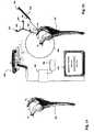
- the tip S of the pointerthus represents an example of an object in real space.
- the method according to the inventioncan be designed so that the tip of the pointer represents an object only if the pointer touches the body structure 100 'and / or if a pointer corresponding input, for example, by an input device 700 is carried out and / or the operator information information eg on the monitor 600 wishes.
- an automatic correctioncan also be carried out according to the invention so that the distances match better or completely.
- the objects (points) P 1 and / or P 2can also be moved.
- Geometric relationship datacan now be defined eg via the distances from Q to one of the points P. However, they can also be defined, for example, using angle relationships that are specified in the FIG. 2a are denoted by ⁇ 2D and ⁇ 3D .
- ⁇ 3Drepresents an angle in space between the connecting line from P 1 to P 2 and from P 2 to Q.
Landscapes
- Health & Medical Sciences (AREA)
- Surgery (AREA)
- Life Sciences & Earth Sciences (AREA)
- Engineering & Computer Science (AREA)
- Medical Informatics (AREA)
- General Health & Medical Sciences (AREA)
- Biomedical Technology (AREA)
- Heart & Thoracic Surgery (AREA)
- Nuclear Medicine, Radiotherapy & Molecular Imaging (AREA)
- Molecular Biology (AREA)
- Animal Behavior & Ethology (AREA)
- Veterinary Medicine (AREA)
- Public Health (AREA)
- Robotics (AREA)
- Oral & Maxillofacial Surgery (AREA)
- Pathology (AREA)
- Apparatus For Radiation Diagnosis (AREA)
- Processing Or Creating Images (AREA)
Description
Translated fromGermanDie vorliegende Erfindung betrifft die Unterstützung der Bestimmung von Korrespondenz-Objekt-Paaren, die dieselben Objekte der selben anatomischen Körperstruktur in verschiedenen Bezugssystemen darstellen. Die bestimmten Korrespondenz-Objekt-Paare können verwendet werden, um eine Navigation relativ zu einer anatomischen Körperstruktur zu ermöglichen.The present invention relates to supporting the determination of correspondence-object pairs representing the same objects of the same anatomical body structure in different reference systems. The particular correspondence object pairs may be used to facilitate navigation relative to an anatomical body structure.
Ein Korrespondenz-Objekt-Paar beschreibt dasselbe Objekt einer anatomischen Körperstruktur in zwei verschiedenen Bezugssystemen. Üblicherweise werden so genannte anatomische Landmarken als Objekte verwendet, da sie in der anatomischen Körperstruktur für den Arzt leicht zu identifizieren sind. Erfindungsgemäß können nicht nur diese Landmarken sondern jegliche anderen Objekte wie z.B. Teile der anatomischen Struktur oder geometrische Primitive, die eine spezielle Beziehung zu der Körperstruktur haben (z.B. Punkte auf der Oberfläche, Symmetrieobjekte, Tangentialobjekte, eingepasste geometrische Objekte, verwendet werden, um Korrespondenz-Objekt-Paare zu bestimmen, und um insbesondere die räumliche Beziehung zwischen den beiden Bezugssystemen zu bestimmen. Letzteres ist die Voraussetzung, um eine Navigation relativ zur Körperstruktur durchzuführen.A correspondence-object pair describes the same object of an anatomical body structure in two different frames of reference. Usually, so-called anatomical landmarks are used as objects, since they are easily identifiable in the anatomical body structure for the physician. According to the invention, not only these landmarks but any other objects such as e.g. Parts of the anatomical structure or geometric primitives that have a special relationship to the body structure (eg points on the surface, symmetry objects, tangent objects, fitted geometric objects, used to determine correspondence-object pairs, and in particular the spatial relationship between The latter is the prerequisite for performing a navigation relative to the body structure.
Üblicherweise gibt es ein (virtuelles) Bezugssystem, in dem eine dreidimensionale räumliche Beschreibungen einer anatomischen Körperstruktur erfolgt, die auf medizinischen Analyseverfahren, wie beispielsweise Magnetresonanz-Tomographie (MRT) oder Computer-Tomographie (CT) basieren, wobei diese Analyseverfahren typischerweise zu einem früheren Zeitpunkt insbesondere präoperativ durchgeführt werden und eine detailreiche Information über die Körperstruktur bieten. Diese detailreiche Information wird insbesondere zur Planung einer Operation verwendet. Es wird nun gewünscht, das virtuelle Bezugssystem, genauer die (virtuellen) Daten über die anatomische Körperstruktur (auf denen beispielsweise die Planung einer Operation beruhen), mit insbesondere interoperativ gewonnenen (realen) Körperstrukturdaten abzugleichen. Hierzu sind üblicherweise Markereinrichtungen an den Körperstrukturen des Patienten, beispielsweise am Knochen (z.B. Pelvis und Femur) angebracht, deren Detektion die Gewinnung realer Körperstrukturdaten erlaubt. (Die Begriffe "real" und "virtuell" werden im Folgenden verwendet, um die vorgenannten Bezugssysteme und die entsprechenden Daten und Objekte zu unterscheiden). Die Lagebeziehung zwischen der anatomischen Körperstruktur und den Markereinrichtungen ist jedoch häufig zu Beginn der Operation nicht bekannt. Um dennoch das virtuelle Bezugssystem mit dem realen abzugleichen, werden üblicherweise mittels eines Pointers so genannte Landmarken der Körperstruktur (interoperativ) berührt. An dem Pointer sind ebenfalls Marker angebracht, deren relative Lage zur Spitze des Pointers bekannt ist, so dass die Spitze des Pointers und damit die Lage der Landmarke durch eine Markerdetektionseinrichtung detektiert werden kann. Diese Markerdetektionseinrichtung detektiert auch die an der Körperstruktur angebrachte Markereinrichtung, so dass sich hieraus die relative Lage zwischen der Markereinrichtung und der Spitze des Pointers und damit die relative Lage zwischen der Markereinrichtung und der Landmarke ergibt. Vorzugsweise werden vom Operateur mindestens drei Landmarken mittels des Pointers im realen Bezugssystem erfasst und in ein Navigationssystem eingelesen. Dieselben (korrespondierenden) Landmarken werden dann im virtuellen Bezugssystem vom Arzt identifiziert. Basierend auf den bestimmten Paaren von korrespondierenden Landmarken, die ein Beispiel für Korrespondenz-Objekt-Paare darstellen, kann dann mit einer gewissen Genauigkeit, die auch von der relativen Lage der Landmarken abhängt, die räumliche Beziehung zwischen dem realen und virtuellen Bezugssystem hergestellt werden. In Folge dessen ist es beispielsweise möglich, ein mit einer Markereinrichtung versehenes Instrument relativ zur anatomischen Körperstruktur zu navigieren, wobei die Lage des Instruments relativ zu den virtuellen Körperstrukturdaten beispielsweise an einem Bildschirm beobachtet werden kann.There is usually a (virtual) frame of reference in which a three-dimensional spatial description of an anatomical body structure is made, based on medical analysis techniques such as magnetic resonance imaging (MRI) or computed tomography (CT), typically at an earlier time especially preoperatively and provide a detailed information about the body structure. This detailed information is used in particular for planning an operation. It is now desired to match the virtual reference system, more precisely the (virtual) data on the anatomical body structure (on which, for example, the planning of an operation is based) with, in particular, interoperatively obtained (real) body structure data. For this purpose, usually marker devices on the body structures of the patient, for example on the bone (eg pelvis and femur) attached, their detection the acquisition of real body structure data allowed. (The terms "real" and "virtual" are used hereafter to distinguish the above reference systems and the corresponding data and objects). However, the positional relationship between the anatomical body structure and the marker means is often unknown at the beginning of the operation. Nevertheless, in order to align the virtual reference system with the real one, so-called landmarks of the body structure (interoperatively) are usually touched by means of a pointer. Also attached to the pointer are markers whose relative position to the tip of the pointer is known, so that the tip of the pointer and thus the position of the landmark can be detected by a marker detection device. This marker detection device also detects the marker device attached to the body structure, resulting in the relative position between the marker device and the tip of the pointer and thus the relative position between the marker device and the landmark. Preferably, at least three landmarks are detected by the operator by means of the pointer in the real frame of reference and read into a navigation system. The same (corresponding) landmarks are then identified by the physician in the virtual frame of reference. Based on the particular pairs of corresponding landmarks that represent an example of correspondence-object pairs, then with some accuracy, which also depends on the relative location of the landmarks, the spatial relationship between the real and virtual frame of reference can be established. As a result, it is possible, for example, to navigate an instrument provided with a marker device relative to the anatomical body structure, wherein the position of the instrument relative to the virtual body structure data can be observed, for example, on a screen.
In der Realität ist die Bestimmung der Landmarken für den Arzt jedoch mit Schwierigkeiten verbunden. Zum einen ist üblicherweise nur ein kleiner Bereich der anatomischen Körperstruktur (z.B. Knochenstruktur) freigelegt, so dass in diesem kleinen Bereich nur wenige markante Oberflächenformen der Körperstruktur vorhanden sind, die als Landmarken verwendet werden können. Anders ausgedrückt ergeben sich größere Unsicherheiten bei der Bestimmung der Landmarken, falls die Oberflächenstruktur des Knochens nicht markant ist.In reality, determining the landmarks for the doctor, however, is fraught with difficulties. On the one hand, usually only a small portion of the anatomical body structure (e.g., bone structure) is exposed, so that in this small area there are only a few distinctive surface shapes of the body structure that can be used as landmarks. In other words, greater uncertainties in the determination of landmarks result if the surface structure of the bone is not prominent.
Aufgabe der Erfindung ist es den Benutzer des Navigationssystems beim Abgleich des realen und virtuellen Bezugssystems und insbesondere bei der Bestimmung von Korrespondenz-Objekt-Paaren (Korrespondenz-Landmarken-Paaren) zu unterstützen.The object of the invention is to assist the user of the navigation system in the comparison of the real and virtual reference system and in particular in the determination of correspondence object pairs (correspondence landmark pairs).
Vorstehende Aufgabe wird durch die Gegenstände der unabhängigen Ansprüche gelöst. Die abhängigen Ansprüche sind auf vorteilhafte Ausführungsformen gerichtet.The above object is solved by the subject matters of the independent claims. The dependent claims are directed to advantageous embodiments.
Wie oben erwähnt, betrifft die vorliegende Erfindung die Bestimmung von Korrespondenz-Objekt-Paaren, die dazu verwendet werden können, um verschiedene Bezugssystem abzugleichen. Diese beiden Bezugssysteme werden im Folgenden A-Bezugssystem und B-Bezugssystem genannt. Das A-Bezugssystem kann beispielsweise das virtuelle Bezugssystem sein und das B-Bezugssystem das reale Bezugssystem. Dies kann aber auch umgekehrt sein, da insbesondere gemäß der Erfindung die Reihenfolge und Abfolge, mit der ein Objekt in einem A-Bezugssystem (als ein A-Objekt) und ein Objekt (B-Objekt) in einem B-Bezugssystem bestimmt wird, beliebig ist, insbesondere alternierend ist und auch mehrere A-Objekte oder B-Objekte hintereinander bestimmt werden können, bevor ein Objekt im jeweils anderen Bezugssystem bestimmt wird. Soweit im Folgenden von einem ersten und zweiten Objekt die Rede ist, wird davon ausgegangen, dass sich die beiden Objekte unterscheiden und verschiedene Teile der Körperstruktur darstellen.As mentioned above, the present invention relates to the determination of correspondence-object pairs that can be used to match different frames of reference. These two reference systems are hereafter referred to as A reference system and B reference system. For example, the A reference system may be the virtual reference system and the B reference system may be the real reference system. However, this can also be reversed since, in particular according to the invention, the order and sequence with which an object is determined in an A-reference system (as an A-object) and an object (B-object) in a B-reference system is arbitrary is, in particular alternating and also several A-objects or B-objects can be determined in succession before an object is determined in the other reference frame. As far as in the following of a first and second object is mentioned, it is assumed that the two objects differ and represent different parts of the body structure.
Erfindungsgemäß werden vorzugsweise geometrische Beziehungen zwischen zwei oder mehr Objekten in einem ersten Bezugssystem genutzt, um im anderen zweiten Bezugssystem korrespondierende Objekte basierend auf den geometrischen Beziehungen zwischen den Objekten im ersten Bezugssystem aufzufinden. Dabei wird insbesondere davon ausgegangen, dass die geometrischen Beziehungen zwischen den Objekten in beiden Bezugssystemen verglichen werden können, wenn es sich um korrespondierende Objekte handelt.According to the invention, geometrical relationships between two or more objects in a first reference system are preferably used to find objects corresponding in the other second reference system based on the geometrical relationships between the objects in the first reference system. In particular, it is assumed that the geometric relationships between the objects in both reference systems can be compared, if they are corresponding objects.
Sind beispielsweise (zwei) A-Objekte im A-Bezugssystem festgelegt und (zwei) B-Objekte im B-Bezugssystem festgelegt, so wird erfindungsgemäß die geometrische Beziehung zwischen den Objekten im jeweiligen Bezugssystem basierend auf der Lage der Objekte im jeweiligen Bezugssystem bestimmt (berechnet). Diese geometrischen Beziehungen werden A-Beziehungsdaten für das A-Bezugssystem genannt und B-Beziehungsdaten für das B-Bezugssystem genannt. Die A-Beziehungsdaten und die B-Beziehungsdaten stellen zusammengenommen Vergleichsdaten dar, die den Vergleich zwischen den A-Beziehungsdaten und den B-Beziehungsdaten ermöglichen. Beispielsweise können sowohl die A-Beziehungsdaten als auch die B-Beziehungsdaten angezeigt werden. Beispielsweise kann der Abstand zwisehen zwei A-Objekten und der Abstand zwischen zwei B-Objekten angezeigt werden. Stimmen die Abstände zumindest in etwa überein, so kann der Bediener, insbesondere Arzt davon ausgehen, dass er zumindest mit einer höheren Wahrscheinlichkeit als ohne die erfindungsgemäße Unterstützung die zwei korrespondierenden Objektpaare korrekt bestimmt hat.If, for example, (two) A objects are defined in the A reference system and (two) B objects defined in the B reference system, according to the invention the geometric relationship between the objects in the respective reference system is determined (calculated) based on the position of the objects in the respective reference system ). These geometric relationships are called A relation data for the A reference frame and B reference data for the B reference frame. The A-related data and the B-related data collectively constitute comparative data that enables the comparison between the A-related data and the B-related data. For example, both the A-relationship data and the B-relationship data may be displayed. For example, the distance can be different Two A-objects and the distance between two B-objects are displayed. If the distances agree at least roughly, then the operator, in particular doctor, can assume that he has correctly determined the two corresponding pairs of objects at least with a higher probability than without the assistance according to the invention.
Vorzugsweise werden automatisch oder beispielsweise durch ein Eingabemittel ein oder mehrere, vorzugsweise mindestens drei Korrespondenz-Objekt-Paare mit Hilfe der Vergleichsdaten basierend auf den festgelegten A-Objekten und B-Objekten bestimmt. Die automatische Bestimmung der Paare kann beispielsweise basierend auf einem Vergleich der Beziehungsdaten erfolgen, falls beispielsweise die Abweichung zwischen den Beziehungsdaten unterhalb eines vorbestimmten Umfanges liegt. Alternativ oder zusätzlich kann eine Bestimmung von Paaren von korrespondierenden Objekten durch einen Bediener erfolgen, indem er beispielsweise festgelegte Objekte (z.B. ein A-Objekt und ein B-Objekt) als korrespondierende Objekte bestimmt. Das erfindungsgemäße Verfahren ist also nicht nur zur Unterstützung der Bestimmung der Lage vom Korrespondenz-Objekt-Paaren geeignet, sondern auch zu deren Bestimmung. Ist eine noch nicht ausreichende Anzahl von Paaren von korrespondierenden Objekten bestimmt, um die Beziehung zwischen den beiden Bezugssystemen vollständig und ausreichend genau zu bestimmen, so kann dennoch basierend auf den bereits bestimmten korrespondierenden Objekt-Paaren (z.B. basierend auf einem korrespondierenden Objektpaar oder auf zwei korrespondierenden Objektpaaren) die räumliche Beziehung zwischen den beiden Bezugssystemen zumindest teilweise bestimmt werden, sofern vorzugsweise bereits mindestens drei Korrespondenz-Objekt-Paare bestimmt oder vorläufig bestimmt sind. Basierend auf dieser teilweisen Bestimmung (die im folgenden auch Ausrichtung oder teilweise Registrierung genannt wird) der A-Objekte im B-Bezugssystem und/oder der B-Objekte im A-Bezugssystem, werden dann Hinweisinformationen für einen Bediener errechnet, die insbesondere auf Punkten, Linien, Flächen oder abgegrenzten Räumen basieren, die Bereiche für potenzielle Korrespondenz-Objekt-Paare darstellen. Durch die Hinweisinformation wird ein Bediener (z.B. akustisch und/oder visuell) darauf hingewiesen, dass er sich in einem derartigen Bereich befindet oder nicht und/oder wie weit er von einem derartigen Bereich entfernt ist. Eine Ausrichtung der beiden Bezugssysteme basierend auf einem oder mehreren gegebenen Korrespondenz-Objekt-Paaren ermöglicht es also erfindungsgemäß, die Hinweisinformationen zu verfeinern und für einen Bediener verständlicher zu gestalten.Preferably, one or more, preferably at least three, correspondence object pairs are determined automatically or for example by an input means with the aid of the comparison data based on the defined A objects and B objects. The automatic determination of the pairs may, for example, be based on a comparison of the relationship data if, for example, the deviation between the relationship data is below a predetermined extent. Alternatively or additionally, a determination of pairs of corresponding objects by an operator can be carried out, for example, by determining fixed objects (eg an A-object and a B-object) as corresponding objects. The method according to the invention is therefore suitable not only for the purpose of determining the position of the correspondence-object pairs, but also for their determination. If a not yet sufficient number of pairs of corresponding objects is determined in order to determine the relationship between the two reference systems completely and with sufficient accuracy, it can nevertheless be based on the already determined corresponding object pairs (eg based on a corresponding object pair or on two corresponding object pairs) Object pairs), the spatial relationship between the two frames of reference at least partially determined, if preferably already at least three correspondence-object pairs are determined or provisionally determined. Based on this partial determination (also referred to below as alignment or partial registration) of the A-objects in the B-reference system and / or the B-objects in the A-reference system, then hint information is calculated for an operator, in particular on points, Lines, surfaces, or bounded spaces that represent areas for potential correspondence-object pairs. The notification information indicates to an operator (eg acoustically and / or visually) that he is in such an area or not and / or how far away he is from such an area. An alignment of the two reference systems based on one or more given correspondence object pairs thus makes it possible according to the invention to refine the hint information and make it more understandable for an operator.
Um die Hinweisinformationen zu verfeinern und weitere Informationen für einen Benutzer erzielen zu können, können alternative oder zusätzlich erfindungsgemäß die A-Objekte, B-Objekte und/oder die später noch erwähnten Hilfsobjekte in einen gemeinsamen Koordinatenraum transformiert oder projiziert werden. Dieser gemeinsame Koordinatenraum ist nicht notwendigerweise ein geometrischer Raum, sondern kann beispielsweise auch ein Merkmalsraum sein. Letzteres ergibt sich beispielsweise, wenn die vorgenannten Objekte einer Fouriertransformation oder einer Formanalyse unterzogen werden, um weitere Vergleichsdaten, insbesondere Vergleichwerte im Koordinatenraum erzielen zu können.In order to refine the hint information and to be able to obtain further information for a user, alternatively or additionally according to the invention the A objects, B objects and / or the auxiliary objects mentioned later can be transformed or projected into a common coordinate space. This common coordinate space is not necessarily a geometric space, but may for example also be a feature space. The latter results, for example, when the aforementioned objects are subjected to a Fourier transformation or a shape analysis in order to be able to achieve further comparison data, in particular comparison values in the coordinate space.
Ist der Bediener mit der Übereinstimmung der Beziehungsdaten nicht zufrieden, so kann er die Lage der Objekte in den jeweiligen Bezugssystemen ändern und/oder durch neue Objekte ersetzen, bis er mit der Übereinstimmung der A-Beziehungsdaten und B-Beziehungsdaten zufrieden ist. Bevorzugt wird ein Bediener dabei diejenigen Objekte ändern bzw. ersetzen, deren Identifikation auf der Körperstruktur als Landmarke schwierig ist und somit mit einer größeren Unsicherheit behaftet ist.If the operator is not satisfied with the match of the relationship data, he may change the location of the objects in the respective frames of reference and / or replace them with new objects until he is satisfied with the correspondence of the A-relationship data and B-relationship data. Preferably, an operator will change or replace those objects whose identification on the body structure as a landmark is difficult and thus afflicted with greater uncertainty.
Vorzugsweise werden erfindungsgemäß die Vergleichsdaten bereitgestellt, die die geometrischen A-Beziehungsdaten und die geometrischen B-Beziehungsdaten umfassen und deren Vergleich ermöglichen. Die bereitgestellten Vergleichsdaten werden erfindungsgemäß in weiteren Schritten verwendet. Beispielsweise, um eine Hinweisinformation für einen Bediener zu erstellen, die beispielsweise die beiden A-Beziehungsdaten und B-Beziehungsdaten anzeigt, um beispielsweise in einem nächsten Schritt einen Vergleich der Vergleichsdaten durchzuführen, und das Vergleichsergebnis (Vergleichswert) beispielsweise im Rahmen einer Hinweisinformation anzuzeigen. Die Vergleichsdaten können weiter verwendet werden, um das Ersetzen von A- und/oder B-Objekten basierend auf den Vergleichdaten manuell oder automatisch durchzuführen. Sie werden beispielsweise weiter dazu verwendet, um die Lage von A-und/oder B-Objekten insbesondere automatisch zu ändern oder deren Änderung durch Hinweisinformationen zu führen. Die bereitgestellten Vergleichsdaten werden insbesondere dazu verwendet, um zu überprüfen, ob die festgelegten A-Objekte und/oder B-Objekte sich für ein Korrespondenz-Objekt-Paar eignen und/oder ob festgelegte Objekt-Paare einer Konsistenzprüfung genügen. Vergleichswerte können insbesondere auch so erzielt werden, dass mehrere berechnete Vergleichswerte kombiniert werden oder aus diesen eine Auswahl getroffen wird. Beispielsweise kann eine Kombination aus dem Vergleich der Abstände und aus einem Vergleich von Winkelbeziehungen herangezogen werden, um einen Vergleichswert z.B. durch Multiplikation zweier Vergleichswerte oder als Maximal-, Minimal- oder Mittelwert der Vergleichswerte zu bestimmen, der dann als Grundlage für eine Hinweisinformation für den Bediener genutzt wird oder basierend auf dem automatisch ein Korrespondenz-Objekt-Paar ausgewählt wird. Auch ist es möglich, nur einen Vergleichswert aus verschiedenen auszuwählen, also beispielsweise nur einen Vergleichswert auszuwählen, der auf einer Winkelbeziehung basiert, aber den Vergleichswert nicht auszuwählen, der sich auf einem Abstand bezieht. Dies kann man je nach gegebener Situation festlegen, um so eine möglichst stabilen und verlässlichen Vergleichswert zu erhalten.Preferably, the comparison data are provided according to the invention, which include the geometric A-related data and the geometric B-related data and allow their comparison. The comparative data provided are used according to the invention in further steps. For example, to prepare an indication information for an operator indicating, for example, the two A-related data and B-related data, for example, to perform comparison of the comparison data in a next step and to display the comparison result (comparative value), for example, as an indication information. The comparison data can be further used to manually or automatically perform the replacement of A and / or B objects based on the comparison data. They are further used, for example, to automatically change the position of A and / or B objects, in particular, or to guide their change by means of pointer information. The provided comparison data is used in particular to check whether the specified A objects and / or B objects are suitable for a correspondence object pair and / or whether specified object pairs satisfy a consistency check. In particular, comparison values can also be achieved in such a way that several calculated comparison values are combined or a selection is made from these. For example, a combination of the comparison of the distances and a comparison of angle relationships are used to determine a comparison value, for example, by multiplying two comparison values or as maximum, minimum or average values of the comparison values, which is then used as the basis for a hint information for the operator or based on automatically a correspondence object pair is selected. It is also possible to select only one comparison value from different, for example to select only one comparison value based on an angular relationship, but not to select the comparison value relating to a distance. This can be determined depending on the given situation in order to obtain the most stable and reliable comparative value possible.
Vorzugsweise wird der Bediener bei der Änderung der Lage eines der Objekte (A-Objekt oder B-Objekt) oder beim Ersetzen eines Objekts durch ein neues Objekt durch Hinweisinformationen unterstützt, die auf den Vergleichsdaten basieren. Dabei wird vorzugsweise die Lage der anderen, nicht zu ersetzenden oder nicht zu ändernden Objekte als gegeben angenommen und die Hinweisinformationen geben einen Hinweis darauf, wie weit die A-Beziehungsdaten und die B-Beziehungsdaten übereinstimmen, während der Bediener beispielsweise die Lage eines Objektes (A-Objekt oder B-Objekt) ändert. Beispielsweise kann akustisch darauf hingewiesen werden, wenn sich die beiden Beziehungsdaten in Hinblick auf den Vergleichswert annähern oder weiter voneinander entfernen. Handelt es sich bei dem Objekt um ein virtuelles Objekt, so kann auf einem Bildschirm basierend auf den geometrischen Beziehungsdaten des realen Raums eine Auswahl virtueller Kandidat-Objekte angezeigt werden, die den Beziehungsdaten des realen Raums entsprechen würden. Ist beispielsweise durch zwei Objekte im realen Raum ein bestimmter Abstand (als reale Beziehungsdaten) vorgegeben und ist im virtuellen Raum nur ein Objekt vorgegeben, so liegen Kandidat-Objekte im virtuellen Raum auf der Oberfläche einer Kugel deren Zentrum mit dem bereits bestimmten Objekt im virtuellen Raum übereinstimmt und deren Radius mit dem Abstand der beiden Objekte im realen Raum übereinstimmt. Genauer liegen die Kandidat-Objekte auf Punkten oder entlang einer Linie oder Linien, die sich durch Schnittbildung zwischen Kugeloberfläche und Oberfläche der Körperstruktur ergeben. Die so angegebenen Information (z.B. angezeigte Kugeloberfläche oder in 2D eine Kreislinie oder Schnittpunkte oder Schnittlinien) ist insbesondere dann hilfreich, wenn das festzulegende Objekt auf einer im Wesentlichen eindimensionalen Körperstruktur, also beispielsweise auf einer gratartigen Körperstruktur oder an einer Kante der Körperstruktur liegt und die Kugeloberfläche den Verlauf und die Oberfläche dieses Grates oder der Kante in einem Winkel, möglichst einem rechtwinkligen Winkel schneidet. In diesem Fall ergeben sich idealer Weise nur einzelne, insbesondere punktförmige Kandidat-Objekte zwischen denen der Bediener dann wählen kann. Weiterhin kann dem Benutzer durch eine vorläufige Registrierung zwischen virtuellem und realem Objekt anhand bereits vorhandener Beziehungsdaten die Ausrichtung der Objekte auf einem Bildschirm angezeigt werden. Damit kann während der Änderung der Objekte die Orientierung im Raum und damit auch das Auffinden der Objekte erleichtert werden.Preferably, the operator is assisted in changing the position of one of the objects (A-object or B-object) or in replacing an object with a new object by hint information based on the comparison data. In this case, it is preferable to assume the location of the other objects not to be replaced or not to be changed, and the hint information gives an indication of how far the A relation data and the B relation data agree, for example, while the operator positions the object (A Object or B object) changes. For example, it can be indicated acoustically if the two relationship data approach or are farther apart with respect to the comparison value. If the object is a virtual object, a selection of virtual candidate objects that would correspond to the relationship data of the real space can be displayed on a screen based on the geometric relationship data of the real space. If, for example, a specific distance (as real relationship data) is predetermined by two objects in real space and if only one object is specified in virtual space, then candidate objects in virtual space on the surface of a sphere are centered on the already determined object in virtual space matches and their radius coincides with the distance of the two objects in real space. More specifically, the candidate objects are located on points or along a line or lines resulting from intersection of sphere surface and surface of the body structure. The information given in this way (eg indicated spherical surface or in 2D a circular line or intersections or cutting lines) is particularly helpful if the object to be determined lies on a substantially one-dimensional body structure, for example on a burr-like body structure or on an edge of the body structure and the spherical surface the course and the surface of this ridge or edge at an angle, preferably a right angle intersects. In this case, ideally only individual, in particular point-shaped candidate objects result between which the operator can then choose. Furthermore, the user can be shown the orientation of the objects on a screen by a preliminary registration between the virtual and the real object based on already existing relationship data. Thus, during the change of the objects the orientation in the space and thus the finding of the objects can be facilitated.
Die vorgenannte Kugel oder Kugeloberfläche stellt ein Beispiel für ein Hilfsobjekt dar, dass verwendet werden kann, um Hinweisinformationen zu generieren. Insbesondere kann die vorgenannte Kugel auf einem Bildschirm angezeigt werden, falls es sich beispielsweise um eine Kugel im virtuellen Raum handelt oder der Bediener kann basierend auf der Kugelform beim Erfassen weiterer Objekte im realen Raum durch Hinweisinformationen geführt werden. Zur Berechnung der Hilfsobjekte kann insbesondere ein automatisches und/oder interaktives Verfahren zur Festlegung bestimmter Objekte, die insbesondere eine vorgegebene Beziehung zur anatomischen Körperstruktur oder zu den festgelegten A-Objekten und/oder B-Objekten haben, verwendet werden. Bei den Objekten kann es sich insbesondere um geometrische Grundkörper, wie Kugel, Quader, Linie, Vieleck usw. handeln. Weiterhin kann es sich bei den Hilfsobjekten um Regionen im virtuellen oder im realen Raum handeln, die beispielsweise dadurch definiert sind, dass der Vergleichswert aller Objekte in der Region in Bezug auf eine Auswahl gegebener Objekte und/oder Körperstrukturen einen bestimmten Wert annimmt oder in einem bestimmten Wertebereich liegt. Dies ist beispielsweise bei der oben angesprochenen Kugeloberfläche der Fall, bei der genau die Region genau die Punkte enthält, die einen festen, aus den Beziehungsdaten berechneten Abstand besitzen. Die Kugeloberfläche kann in der Folge mit der anatomischen Körperstruktur geschnitten werden, um eine weitere Einschränkung der Auswahlpunkte und damit eine spezifischere Konstruktion der Hilfsobjekte zu erreichen.The aforementioned sphere or sphere represents an example of a helper object that can be used to generate clue information. In particular, the aforementioned ball can be displayed on a screen, if it is, for example, a ball in virtual space or the operator can be guided based on the spherical shape when detecting other objects in real space by hint information. In particular, an automatic and / or interactive method for determining specific objects, which in particular have a predetermined relationship to the anatomical body structure or to the defined A objects and / or B objects, can be used to calculate the auxiliary objects. The objects may in particular be geometric basic bodies, such as sphere, cuboid, line, polygon, etc. Furthermore, the auxiliary objects can be regions in virtual or real space, which are defined, for example, in that the comparison value of all objects in the region assumes a specific value or in a specific value with respect to a selection of given objects and / or body structures Range of values is. This is the case, for example, in the case of the above-mentioned spherical surface, in which precisely the region contains exactly the points which have a fixed distance calculated from the relationship data. The spherical surface can subsequently be cut with the anatomical body structure in order to achieve a further restriction of the selection points and thus a more specific construction of the auxiliary objects.
Hilfsobjekte können beispielsweise durch Einpassen geometrischer Strukturen, wie beispielsweise geometrischer Grundkörper in zumindest Teile der anatomischen Struktur festgelegt werden. Beispielsweise kann an den Grat einer Knochenstruktur (beispielsweise Vorderkante des Acromions) eine Tangente angelegt werden, oder auf die Glenoidoberfläche eine Ebene angepasst werden. Ein weiteres Beispiel wäre die Einpassung einer Kugel in die durch die Genoidoberfläche umschriebenen Vertiefung. Die vorgenannten Vergleichswerte und/oder Vergleichsdaten können auch herangezogen werden, um die Hilfsobjekte zu bestimmen. Insbesondere könne die Objekte so gewählt werden, dass sich für sie die optimalen Vergleichswerte ergeben. Die Vergleichswerte werden dabei beispielsweise so bestimmt, dass die geometrischen Eigenschaften der Hilfsobjekte im A-Bezugssystem und im B-Bezugssystem untereinander verglichen werden. Beispielsweise können in beiden Bezugssystemen je eine Kugel eingepasst werden und die Durchmesser der Kugeln werden dann verglichen. Auch können aus der geometrischen Beziehung zwischen verschiedenen Hilfsobjekten, beispielsweise einer Winkelbeziehung zwischen zwei Ebenen, geometrische Beziehungsdaten zwischen Hilfsobjekten in beiden Bezugssystemen bestimmt werden. Diese geometrischen Beziehungsdaten können kann wiederum verglichen werden, um einen Vergleichswert zu erzielen.Auxiliary objects can be defined, for example, by fitting geometric structures, such as, for example, geometric basic bodies in at least parts of the anatomical structure. For example, a tangent may be applied to the ridge of a bone structure (eg leading edge of the acromion), or a plane adapted to the glenoid surface. Another example would be fitting a ball into it the genoid surface circumscribed depression. The aforementioned comparison values and / or comparison data can also be used to determine the auxiliary objects. In particular, the objects can be chosen so that the optimal comparison values result for them. For example, the comparison values are determined such that the geometric properties of the auxiliary objects in the A reference system and in the B reference system are compared with one another. For example, in each case one ball can be fitted in both reference systems and the diameters of the balls are then compared. Also, geometric relationship data between helper objects in both frames can be determined from the geometric relationship between various helper objects, such as an angular relationship between two planes. This geometric relationship data can in turn be compared to achieve a comparison value.
Um Korrespondenz-Objekt-Paare zu bestimmten, kann auf verschiedene Weise vorgegangen werden. Beispielsweise können eine Vielzahl von A-Objekten und B-Objekten festgelegt werden, die je paarweise Kandidaten für Korrespondenz-Objekt-Paare darstellen. Aus dieser Vielzahl von Kandidat-Objekten werden dann vom Bediener oder automatisch insbesondere diejenigen Paare ausgewählt, für die sich die beste Übereinstimmung der geometrischen Beziehungsdaten (A-Beziehungsdaten und B-Beziehungsdaten) ergibt.In order to determine correspondence object pairs, it is possible to proceed in different ways. For example, a plurality of A-objects and B-objects may be designated, which are pairs of candidates for correspondence-object pairs. From this plurality of candidate objects, the operator or automatically selects, in particular, those pairs for which the best match of the geometric relationship data (A-relationship data and B-relationship data) results.
Alternativ kann auch schrittweise vorgegangen werden. Dies bedeutet, dass beispielsweise ein Teil der bereits festgelegten A-Objekte und B-Objekte als zumindest vorläufig gegebene Korrespondenz-Objekt-Paare angenommen werden kann. So kann beispielsweise auch nur mit einem einzigen Paar aus einem A-Objekt und einem B-Objekt begonnen werden. Vorzugsweise ist dies ein Paar, das auf einer besonders markanten und leicht bestimmbaren Landmarke beruht. Ausgehend hiervon kann dann in einem der beiden Bezugssysteme ein weiteres Objekt ausgewählt werden. Hierzu kann auch auf Datenbankinformationen zurückgegriffen werden, die Informationen über typische Abstände und Lagebeziehungen zwischen der ersten bestimmten Landmarke und der als zweiten zu bestimmenden Landmarke beinhalten. Beispielsweise kann basierend auf dieser Information der wahrscheinliche Bereich für die zweite Landmarke in einer Anzeige bildlich hervorgehoben werden. Ein Bediener wählt dann die zweite Landmarke aus. Basierend auf der geometrischen Beziehung zwischen der ersten und der zweiten Landmarke (im realen oder virtuellen Raum) wird dann die Bestimmung der zweiten Landmarke im jeweils anderen Raum (virtueller oder realer Raum) durch Hinweisinformationen (Vergleichsdaten) unterstützt. Die nun bestimmten Objekte können als zumindest vorerst gegebene Korrespondenzpaare angenommen werden, um hierauf basierend dann weitere Korrespondenzpaare zu bestimmen.Alternatively, it is also possible to proceed step by step. This means that, for example, a part of the already defined A objects and B objects can be assumed as at least provisionally given correspondence object pairs. For example, you can start with only a single pair of an A-object and a B-object. Preferably, this is a pair based on a particularly distinctive and easily identifiable landmark. Starting from this, a further object can then be selected in one of the two reference systems. For this purpose, it is also possible to resort to database information which contains information about typical distances and positional relationships between the first specific landmark and the second landmark to be determined. For example, based on this information, the probable area for the second landmark may be highlighted in a display. An operator then selects the second landmark. Based on the geometric relationship between the first and the second landmark (in real or virtual space) then the determination of the second landmark in each other's space (virtual or real space) by hint information (Comparative data) supported. The now determined objects can be assumed as correspondence pairs given at least for the time being in order to then determine further correspondence pairs based thereon.
Sind mehrere Korrespondenzpaare gegeben, vorzugsweise mindestens drei, so werden vorzugsweise Konsistenzüberprüfungen durchgeführt. Mittels dieser Konsistenzüberprüfungen wird überprüft, ob bisher als Korrespondenz-Objekt-Paare (zumindest vorerst) festgelegte Objektpaare aus jeweils einem A-Objekt und einem B-Objekt nicht nur bezüglich einem weiteren Objektpaar eine gute Übereinstimmung der geometrischen Beziehungsdaten aufweisen (gute Übereinstimmung heißt z.B. eine Übereinstimmung in einem vorbestimmten Umfang), sondern auch bezüglich anderer (inzwischen bestimmter) Objektpaare. Sind beispielsweise drei Objektpaare bestimmt und wurde das Objektpaar eins und zwei basierend darauf bestimmt, dass die geometrische Beziehung zwischen dem ersten A-Objekt und dem zweiten A-Objekt mit der geometrischen Beziehung zwischen dem ersten B-Objekt und dem zweiten B-Objekt übereinstimmt und wurde das dritte Objektpaar so bestimmt, dass die geometrische Beziehung zwischen dem zweiten A-Objekt und dem dritten A-Objekt mit der geometrischen Beziehung zwischen dem zweiten B-Objekt und dem dritten B-Objekt übereinstimmt, so kann man dies mit einer Konsistenzüberprüfung überprüfen. Dabei wird die geometrische Beziehung zwischen dem ersten A-Objekt und dem dritten A-Objekt mit der geometrischen Beziehung zwischen dem ersten B-Objekt und dem dritten B-Objekt verglichen. Stellt sich auch hier eine gute Übereinstimmung ein, so kann man die gewonnenen drei Objektpaare als Korrespondenz-Objekt-Paare festlegen. Ist die Übereinstimmung nicht zufrieden stellend oder will man noch weitere Objektpaare bestimmen, so kann man die Objektpaare als Kandidat-Objektpaare auffassen, wobei die einzelnen A-Objekte und B-Objekte noch geändert werden können, um eine bessere Übereinstimmung der geometrischen Beziehungsdaten zu erzielen. Zu diesem Zweck können vorher festgelegte Objekte durch neue Objekte ersetzt werden oder die Lage festgelegter Objekte kann geändert werden. Im virtuellen Raum erfolgt dies beispielsweise durch das Verschieben eines Objekts vom Bildschirm mittels der Maus. Im realen Raum kann dies durch eine Bewegung des Pointers von einem Oberflächenpunkt auf der Körperstruktur zu einem anderen Oberflächenpunkt erfolgen.If there are several correspondence pairs, preferably at least three, consistency checks are preferably carried out. By means of these consistency checks, it is checked whether, as correspondence object pairs (at least for now), fixed object pairs from respectively one A object and one B object have a good match of the geometric relationship data not only with respect to a further object pair (good match is eg a Agreement in a predetermined extent), but also with respect to other (now certain) object pairs. For example, if three object pairs are determined, and object pair one and two were determined based on the geometric relationship between the first A object and the second A object coinciding with the geometric relationship between the first B object and the second B object, and if the third object pair has been determined such that the geometric relationship between the second A object and the third A object matches the geometric relationship between the second B object and the third B object, then this can be checked with a consistency check. In this case, the geometric relationship between the first A-object and the third A-object is compared with the geometric relationship between the first B-object and the third B-object. If a good match also occurs here, then the three object pairs obtained can be defined as correspondence object pairs. If the match is unsatisfactory or if one wants to determine further pairs of objects, then one can regard the object pairs as candidate-object pairs, whereby the individual A-objects and B-objects can still be changed in order to achieve a better match of the geometric relationship data. For this purpose, predefined objects can be replaced by new objects or the position of specified objects can be changed. In virtual space, this is done, for example, by moving an object from the screen using the mouse. In real space, this can be done by moving the pointer from one surface point on the body structure to another surface point.
Insbesondere ist das Verfahren vorzugsweise so gestaltet, dass ein Bediener automatisch aufgefordert wird, Objekte zu ändern oder neue Objekte einzugeben, die ein zusätzliches Objekt darstellen sollen oder bestehende Objekte ersetzen sollen, wenn ein Vergleich der A-Beziehungsdaten mit den B-Beziehungsdaten (also basierend auf den Vergleichsdaten) nicht zu einem zufrieden stellenden Ergebnis führt oder wenn z.B. durch eine automatische Überprüfung festgestellt wird, dass die Beziehungsdaten vorbestimmte Kriterien nicht erfüllen. Ein derartiges Kriterium ist beispielsweise gegeben, wenn alle bisher festgelegten Objekte im jeweiligen Bezugssystem im Wesentlichen auf einer Gerade liegen. Im Wesentlichen bedeutet hierbei insbesondere, dass sie innerhalb eines vorbestimmten Zylinders liegen, dessen Radius beispielsweise weniger als 30 % oder weiniger als 10 % der Höhe des Zylinders beträgt. In diesem Fall kann davon ausgegangen werden, dass aus den bisher bestimmten Korrespondenz-Objekt-Paaren die räumliche Beziehung zwischen dem virtuellen und realen Raum noch nicht mit einer ausreichenden Sicherheit bestimmt werden kann. Ein anderes Beispiel ist gegeben, wenn die bisher bestimmten Objekte in einem der beiden Räume im Wesentlichen auf einer Ebene liegen. Im Wesentlichen bedeutet hier beispielsweise, dass ein Raum, bei dem die festgelegten Objekte die Ecken bilden, eine vorbestimmte maximale Höhe hat, die beispielsweise weniger als 20 % oder weniger als 10 % des Abstandes zwischen den am weitesten entfernten Objekten beträgt. Alternativ zu den vorgenannten Kriterien kann man beispielsweise basierend auf der Detektionsgenauigkeit der Markereinrichtungen oder der Genauigkeit der Skalierung der Analysedaten, auf denen die virtuell dargestellten Körperstrukturen basieren, weitere absolute Kriterien einführen. Beispielsweise, kann man festlegen, dass die vorgenannte Höhe des beschriebenen Raums oder der vorgenannte Radius des Zylinders eine Mindestgröße aufweist, die z.B. zumindest 5 mm oder mindestens 1 cm beträgt oder ein anderes geeignetes absolutes Kriterium gewählt wird. Insgesamt müssen also ausreichend viele, die räumliche Beziehung der Bezugssysteme betreffende Parameter aus den bestimmten Objekt-paaren bestimmbar sein, um die räumliche Beziehung zwischen den vorgenannten Räumen eindeutig festzulegen. Diese Parameter (z.B. Abstände zwischen Objekten; Winkel zwischen Linien, die Objekte verbinden; Winkel zwischen Ebenen, die durch Objekte gebildet werden etc.) werden auch als Freiheitsgrad bezeichnet. Eine Aufforderung durch das Verfahren, weitere Objekte zu bestimmen, erfolgt also vorzugsweise dann, wenn noch nicht alle die räumliche Beziehung der beiden Bezugssysteme betreffende Freiheitsgrade (mit einer ausreichenden Genauigkeit) bestimmbar sind.In particular, the method is preferably designed so that an operator is automatically requested to change objects or to enter new objects that are an additional object should or should replace existing objects, if a comparison of the A-relationship data with the B-relationship data (ie based on the comparison data) does not lead to a satisfactory result or if, for example, it is determined by an automatic check that the relationship data not predetermined criteria fulfill. Such a criterion is given, for example, if all previously defined objects in the respective frame of reference lie substantially on a straight line. In essence, this means in particular that they lie within a predetermined cylinder whose radius is, for example, less than 30% or less than 10% of the height of the cylinder. In this case, it can be assumed that the spatial relationship between the virtual and real space can not yet be determined with sufficient certainty from the previously determined correspondence object pairs. Another example is given when the previously determined objects in one of the two rooms lie substantially on one level. Essentially, here, for example, means that a space where the fixed objects form the corners has a predetermined maximum height that is, for example, less than 20% or less than 10% of the distance between the farthest objects. As an alternative to the aforementioned criteria, further absolute criteria can be introduced, for example, based on the detection accuracy of the marker devices or the accuracy of the scaling of the analysis data on which the virtual body structures are based. For example, one can specify that the aforementioned height of the described space or the aforementioned radius of the cylinder has a minimum size, for example, is at least 5 mm or at least 1 cm or another suitable absolute criterion is selected. All in all, therefore, a sufficient number of parameters relating to the spatial relationship of the reference systems must be determinable from the specific object pairs in order to clearly define the spatial relationship between the aforementioned spaces. These parameters (eg distances between objects, angles between lines connecting objects, angles between planes formed by objects, etc.) are also called degrees of freedom. A request by the method to determine further objects, therefore, preferably takes place when not all the degrees of freedom relating to the spatial relationship of the two reference systems can be determined (with sufficient accuracy).
Die vorgenannte Eingabe weiterer Objekte und die Durchführung eines Vergleichs kann insbesondere z. T. automatisch durchgeführt werden. Erfindungsgemäß können automatisch die geometrischen A-Beziehungsdaten und B-Beziehungsdaten verglichen werden. Beispielsweise kann automatisch der Abstand zwischen zwei A-Objekten mit dem Abstand zwischen zwei B-Objekten verglichen werden. Ist eine gute Übereinstimmung gegeben, stimmt also beispielsweise der Abstand mindestens zu einem vorbestimmten Prozentsatz überein, der insbesondere mindestens 90 % oder insbesondere 99 % beträgt und/oder ist die Abweichung kleiner als ein vorbestimmter Absolutbetrag, der z.B. kleiner 1 cm, 5 mm oder 1 mm ist, so wird ein entsprechendes Hinweissignal ausgegeben.The aforementioned input of other objects and the implementation of a comparison can in particular z. T. be carried out automatically. According to the invention can automatically geometric A-relationship data and B-relationship data. For example, the distance between two A-objects can be automatically compared with the distance between two B-objects. If there is a good match, for example, the distance is at least equal to a predetermined percentage, which is in particular at least 90% or in particular 99% and / or the deviation is less than a predetermined absolute value, for example less than 1 cm, 5 mm or 1 mm, a corresponding warning signal is output.
Alternativ oder zusätzlich kann basierend auf dem Vergleichsergebnis die Lage eines Objekts automatisch geändert werden. Sind beispielsweise zwei reale Objekte und zwei virtuelle Objekte vorgegeben, so kann die Lage eines der beiden virtuellen Objekte oder auch beider virtueller Objekte basierend auf dem Vergleichsergebnis automatisch geändert werden, bis sich eine gute oder vollständige Übereinstimmung der Beziehungsdaten ergibt. Bei der Änderung der Lage wird vorzugsweise von den bereits z.B. durch einen Bediener gegebenen (aber mit Ungenauigkeit behafteten) Lagen der virtuellen Objekte ausgegangen. Die Änderung der Lage oder der Lagen kann im vorgenannten Beispiel beispielsweise so erfolgen, dass (automatisch) entlang der Oberfläche der Körperstruktur die Lage eines Objekts so verändert wird, dass es sich näher auf das andere Objekt zu bewegt oder weiter davon weg, je nachdem wie sich eine bessere Übereinstimmung ergibt. Insbesondere kann auch noch eine zusätzliche Zwangsbedingung bei der automatischen Lageänderung eingeführt werden, beispielsweise dahingehend, dass sich das Objekt entlang einer Kante oder einer Gratlinie in der Körperstruktur zur Lageänderung bewegen muss.Alternatively or additionally, based on the result of the comparison, the position of an object can be changed automatically. If, for example, two real objects and two virtual objects are specified, then the position of one of the two virtual objects or even of both virtual objects can be changed automatically based on the result of the comparison until a good or complete correspondence of the relationship data results. When changing the position, it is preferable to use the already e.g. assumed by an operator (but with inaccuracy afflicted) layers of the virtual objects. For example, in the above example, the change in position or positions may be made so that (automatically) along the surface of the body structure, the position of an object is changed so as to move closer to or further away from the other object, as the case may be a better match results. In particular, an additional constraint condition may also be introduced in the automatic positional change, for example to the effect that the object must move along an edge or a ridgeline in the body structure for the change in position.
Insbesondere wenn dies zu keinem zufrieden stellenden Ergebnis führt, kann der Bediener aufgefordert werden, die Lage des realen oder auch des virtuellen Objekts zu ändern. Insgesamt kann durch eine iterative Vorgehensweise (z.B. durch Änderung der Lage verschiedener realer und/oder virtueller Objekte) die Übereinstimmung der korrespondierenden Beziehungsdaten verbessert werden und insbesondere eine gute Konsistenz erzielt werden. Ist beispielsweise ein gewisses Schema vorgegeben, in welcher Reihenfolge bestimmte Landmarken zu bestimmen sind, so können mit Hilfe des erfindungsgemäßen Systems bei verschiedenen Patienten in sehr vergleichbarer Weise Korrespondenzpaare bestimmt werden, so dass die Vergleichbarkeit von Operationsergebnissen erhöht wird. Dies unterstützt auch die Verlässlichkeit statistisch erhobener Daten über den Operationsverlauf und erhöht die Sicherheit bei der Landmarkenbestimmung für den Arzt.In particular, if this does not lead to a satisfactory result, the operator may be asked to change the position of the real or the virtual object. Overall, by an iterative procedure (eg by changing the position of various real and / or virtual objects), the correspondence of the corresponding relationship data can be improved and, in particular, a good consistency can be achieved. If, for example, a certain scheme is specified in which order certain landmarks are to be determined, correspondence pairs can be determined in a very comparable manner with the aid of the system according to the invention for different patients, so that the comparability of surgical results is increased. This also supports the reliability statistically collected data on the course of the operation and increases the safety in landmark determination for the doctor.
Die Erfindung erlaubt somit die Optimierung der Erfassung von Objekten, insbesondere von Landmarken und die Optimierung der Definition von Objekten bzw. Landmarken zur (automatischen oder manuellen) Bestimmung von Korrespondenz-Objekt-Paaren. Insbesondere kann, falls als Ausgangspunkt eine sehr genau bestimmbare Landmarke gegeben ist, die Bestimmung anderer Landmarken (Objekte) optimiert werden. Insbesondere ist das Verfahren vorteilhaft, falls Objekte, insbesondere weitere Landmarken auf einer Kante der Oberfläche der Körperstruktur liegen. In diesem Fall gibt es im Wesentlichen nur einen einzigen Freiheitsgrad, der für die Erfassung des Objekts übrig geblieben ist, nämlich entlang der Kante bzw. entlang des Grates. Der Abstand der Objekte ist das Kriterium, um den verbliebenen Freiheitsgrad fest zu legen. Das Objekt muss auf dem Schnittpunkt zwischen der Kante und einer Kugeloberfläche liegen, die die erste Landmarke als Zentrum hat und den Abstand der geplanten Landmarken als Radius. Vorzugsweise wird hierbei darauf geachtet, dass die Orientierung der Kante nicht (ungefähr) gleich der Richtung zwischen den Landmarken (Objekten) ist.The invention thus allows the optimization of the detection of objects, in particular of landmarks and the optimization of the definition of objects or landmarks for (automatic or manual) determination of correspondence object pairs. In particular, if a very accurately definable landmark is given as the starting point, the determination of other landmarks (objects) can be optimized. In particular, the method is advantageous if objects, in particular further landmarks lie on an edge of the surface of the body structure. In this case, there is essentially only one degree of freedom left over for the detection of the object, namely along the edge or along the ridge. The distance of the objects is the criterion for determining the remaining degree of freedom. The object must be at the intersection between the edge and a sphere surface that has the first landmark as its center and the distance of the planned landmarks as a radius. Preferably, care is taken here that the orientation of the edge is not (approximately) equal to the direction between the landmarks (objects).
Falls bereits zwei Objekte (Landmarken) erfasst worden sind, kann man wie folgt insbesondere gemäß der vorliegenden Erfindung vorgehen. Die Erfassung der dritten Landmarke kann geführt werden, indem man die Abstände zu den zwei vorhergehend definierten Objekten (Landmarken) zeigt. Der verbliebene Freiheitsgrad kann leicht eingestellt werden, falls das Objekt auf der Oberfläche der Körperstruktur liegen muss. Das Objekt muss am Schnittpunkt der Oberfläche der Körperstruktur und den zwei Kugeloberflächen liegen, wobei die Kugeloberflächen die ersten Landmarken als Zentrum haben und die Abstände der geplanten Landmarken als ihren jeweiligen Radius haben.If two objects (landmarks) have already been detected, one can proceed as follows, in particular according to the present invention. The detection of the third landmark can be guided by showing the distances to the two previously defined objects (landmarks). The remaining degree of freedom can easily be adjusted if the object must lie on the surface of the body structure. The object must be at the intersection of the surface of the body structure and the two spherical surfaces, with the spherical surfaces having the first landmarks as a center and the distances of the planned landmarks as their respective radius.
Bei vielen praktischen Fällen (z.B. der Registrierung des Pelvis bei Hüftoperationen in lateraler Position, bei der Skapularegistrierung bei Schulteroperationen, bei der Registrierung von Wirbeln bei minimal invasiver Wirbelsäulenoperation), ist es schwierig, mit ausreichender Genauigkeit reproduzierbare Landmarken zu definieren. Die vorliegende Erfindung erlaubt es, ein Verfahren durchzuführen, um mehrere Landmarken zu erzeugen. Dieses Verfahren beruht auf vorerfasster Information (Analysedaten) und auf geometrischen bzw. topologisehen Eigenschaften der Oberfläche der Körperstruktur. Das vorliegende Verfahren stellt eine unterstützende Information oder hilfreiche Führungshinweise für einen Arzt bereit, um diese Landmarken in reproduzierbarer Weise mit der Unterstützung des erfindungsgemäßen Verfahrens zu bestimmen. Der Registrierungsprozess wird robuster und stabiler, wenn man mehrere Landmarken bzw. Objekte verwendet.In many practical cases (eg registering the pelvis for hip surgery in a lateral position, scapular registration for shoulder surgery, registering vertebrae in minimally invasive spine surgery), it is difficult to define reproducible landmarks with sufficient accuracy. The present invention allows to perform a method to generate multiple landmarks. This method is based on vorerfasster information (analysis data) and on geometric or topologisehen Properties of the surface of the body structure. The present method provides supportive information or helpful guidance to a physician to reproducibly determine these landmarks with the assistance of the method of the invention. The registration process becomes more robust and stable when using multiple landmarks or objects.
Zusätzlich können die Punkte hinsichtlich ihrer Konsistenz überprüft werden. Falls zumindest drei Landmarken erfasst worden sind, kann die Konsistenz der Bestimmung, z.B. der Punktabstand geprüft werden, indem beispielsweise zyklisch von Objekt zu Objekt die Überprüfung durchgeführt wird und Objektlagen gegebenenfalls angepasst werden. Dieses Verfahren zur Überprüfung der Konsistenz kann verbessert werden, falls mehr als drei Objekte durch das erfindungsgemäße Verfahren festgelegt werden. Insbesondere können Objekte neu festgelegt werden oder die Lage der Objekte kann geändert werden. Die Abfolge der Objektfestlegung kann insbesondere einem vorgegebenen Schema folgen, das beispielsweise der Arzt vorher geplant hat.In addition, the points can be checked for consistency. If at least three landmarks have been detected, the consistency of the determination, e.g. the point distance are checked, for example, by checking cyclically from object to object and object positions are adjusted if necessary. This method of checking the consistency can be improved if more than three objects are determined by the method according to the invention. In particular, objects can be redefined or the location of the objects can be changed. In particular, the sequence of object definition can follow a predetermined pattern which, for example, the physician has previously planned.
Das erfindungsgemäße Verfahren unterstützt den Arzt auch bei dem Erlernen der Bestimmung von Landmarken, da dem Arzt eine direkte Rückkopplung darüber gegeben wird, wie gut er die Landmarken festgelegt hat und ob die festgelegte Landmarke mit den bisher festgelegten Landmarken konsistent ist. In der Praxis gab es erhebliche Unterschiede, z.B. 10 bis 15 mm zwischen den erfassten und den geplanten Objekten bzw. Landmarken, falls die Landmarken frei von einem Arzt bestimmt wurden. Das erfindungsgemäße Verfahren erlaubt es, die Genauigkeit der Festlegung von Korrespondenz-Objekt-Paare und insbesondere von Landmarken zu erhöhen. Wie bereits oben erwähnt wird die Erfindung genutzt, um Objekte, insbesondere spezifische Landmarken bei einem Registrierungsprozess, wie er bei der medizinischen Navigation eingesetzt wird, (im realen Raum) zu erfassen oder (im virtuellen Raum) zu definieren. Das System unterstützt den Chirurgen bei der Erfassung bzw. Definition von Objekten, indem bereits verfügbare Information gezeigt wird, und/oder (automatisch) verwendet wird. Die Information kann beispielsweise auf einem Computermonitor angezeigt werden und/oder auch akustisch angegeben werden oder sie kann automatisch bei einem Algorithmus (Programm) zur Definition von Landmarken bzw. Objekten genutzt werden.The method according to the invention also assists the physician in learning the determination of landmarks, since the physician is given direct feedback on how well he has set the landmarks and whether the fixed landmark is consistent with the previously established landmarks. In practice, there were significant differences, for example 10 to 15 mm between the registered and the planned objects or landmarks, if the landmarks were determined free of a doctor. The method according to the invention makes it possible to increase the accuracy of the definition of correspondence object pairs and in particular of landmarks. As already mentioned above, the invention is used to capture objects (in particular real landmarks) in a registration process, as used in medical navigation (in real space), or to define them (in virtual space). The system assists the surgeon in capturing or defining objects by showing already available information and / or (automatically) using it. The information can for example be displayed on a computer monitor and / or also indicated acoustically or it can be used automatically in an algorithm (program) for the definition of landmarks or objects.
Ein Vergleichswert ist insbesondere ein Maß für die Abweichung der zum Vergleich herangezogenen A-Beziehungsdaten und B-Beziehungsdaten voneinander (z.B. Abstand von Punkten, Abstände zu Punkten oder Linien bzw. allgemeine geometrische Distanzen, Winkelabweichungen, Distanz- oder Winkelabweichungen in Projektionen). Der berechnete Wert kann ein beliebiger, von einem Algorithmus berechneter Vergleichswert sein. Dabei können Algorithmen zur Ausrichtung (z.B. Registrierung zwischen A-Objekt und B-Objekt anhand bereits vorliegender Korrespondenzinformationen) und zum Vergleich der Strukturen in einer geeigneten mathematischen Darstellung (z.B. Transformation in ein geeignetes Koordinatensystem ggf. unter Berücksichtigung von Gewichtungen der einzelnen Koordinatenkomponenten) mit verwendet werden.In particular, a comparison value is a measure of the deviation of the A-relationship data used for comparison and B-relationship data from each other (e.g., distance of points, distances to points or lines or general geometric distances, angular deviations, distance or angle deviations in projections). The calculated value can be any comparison value calculated by an algorithm. In this case, algorithms for alignment (eg registration between A-object and B-object based on already existing correspondence information) and for comparing the structures in a suitable mathematical representation (eg transformation into a suitable coordinate system, possibly taking into account weightings of the individual coordinate components) used become.
Zusätzlich kann die Erfindung verwendet werden, um den Arbeitsablauf bei dem Erfassungsprozess zu steuern, indem die Konsistenz der erfassten Objekte basierend auf Kriterien überprüft wird.In addition, the invention may be used to control the workflow in the capture process by checking the consistency of the captured objects based on criteria.
Das Kriterium ist gemäß einer Ausführungsform gültig zwischen einigen Paaren oder jedem Paar eines n-Tupels von Objekten. Ein Wert, der die Konsistenz darstellt oder eine visuelle Darstellung der Konsistenz kann beispielsweise auf einem Monitor ausgegeben werden oder z.B. akustisch angezeigt werden. Die oben genannten Vergleichswerte, die insbesondere zwischen verschiedenen Objektpaaren gelten, können mathematisch verarbeitet werden, um einen Wert für eine Konsistenz zu errechnen. Beispielsweise können als Konsistenzwert ein mittlerer Vergleichswert aller bestimmten Vergleichswerte herangezogen werden oder der maximale Vergleichswert, der beispielsweise eine maximale Abweichung von A-Beziehungsdaten von den B-Beziehungsdaten darstellt. Geht man beispielsweise davon aus, dass ein guter Vergleichswert für die Beziehung zwischen dem ersten und zweiten Objektpaar und dem zweiten und dritten Objektpaar gegeben ist, also beispielsweise eine geringe Differenz der Abstände, und das aber zwischen dem ersten und dritten Objektpaar ein schlechter Vergleichswert, also beispielsweise eine große Differenz zwischen den Abständen gegeben ist, so kann dieser maximale Vergleichswert mit der größten Differenz als Kriterium für die Konsistenz, also als Konsistenzwert herangezogen werden. Alternativ kann der Mittelwert der Differenz oder eine andere Kombination der Vergleichswerte, als Konsistenzwert bestimmt werden.The criterion is valid between some pairs or each pair of an n-tuple of objects according to one embodiment. A value that represents the consistency or a visual representation of the consistency can, for example, be output on a monitor or, for example, displayed acoustically. The aforementioned comparison values, which in particular apply between different object pairs, can be processed mathematically in order to calculate a value for a consistency. For example, the consistency value used may be an average comparison value of all specific comparison values or the maximum comparison value representing, for example, a maximum deviation of A relation data from the B relationship data. Assuming, for example, that there is a good comparison value for the relationship between the first and second object pair and the second and third object pair, that is, for example, a small difference of the distances, but that between the first and third object pair a poor comparison value, ie For example, given a large difference between the distances, this maximum comparison value with the largest difference can be used as a criterion for the consistency, ie as a consistency value. Alternatively, the mean value of the difference or another combination of the comparison values can be determined as the consistency value.
Alternativ oder zusätzlich kann eine neue Erfassung von Objekten automatisch gefordert werden, z.B. falls die Konsistenz automatisch als nicht ausreichend befunden wird oder vom Bediener als nicht ausreichend angesehen wird.Alternatively or additionally, a new detection of objects may be automatically requested, e.g. if the consistency is automatically found to be insufficient or is considered by the operator to be insufficient.
Die Erfassung von Objekten bedeutet hierin insbesondere jegliches Verfahren, um eine Koordinateninformation über Objekte, insbesondere Landmarken zu erhalten. Die Notwendigkeit einer derartigen Erfassung ist insbesondere bei einer interoperativen Situation gegeben. Die Erfassung von Landmarken stellt also insbesondere die Erfassung von Koordinaten relativ zu einer Markereinrichtung (z.B. der Referenzstern, der an einem Knochen befestigt ist) dar. Diese Erfassung kann durch eine jegliche Vorrichtung oder durch ein jegliches Verfahren durchgeführt werden, um eine derartige Lageinformation über die Lage eines Objekts zu erfassen. Beispielsweise kann eine Erfassungseinrichtung, die die vorgenannte Markeinrichtung und beispielsweise einen Pointer oder ein kalibriertes Instrument, insbesondere mit einer daran angebrachten Markereinrichtung, umfasst und die insbesondere eine Detektionseinrichtung zum Detektieren der Markereinrichtung und zum Weiterleiten der Detektionssignale an eine Datenverarbeitungsvorrichtung umfasst, verwendet werden. Auch können Punkte oder Objekte in registrierten Bilddaten (z.B. Fluoroskopiebildern) festgelegt werden. Bilddaten sind dann registriert, wenn den durch sie beschriebenen Bildpunkten eine räumliche Position in einem Bezugssystem zugeordnet werden kann, das insbesondere bezüglich einer an einer Körperstruktur angebrachten (und insbesondere zur Navigation verwendeten) Markereinrichtung ortsfest ist. Die Erfassung von Bilddaten (Fluoroskopiebilder) stellt ein weiteres Beispiel für interoperativ eingesetzte Analyseverfahren dar, mit deren Hilfe reale Objekte im realen Raum relativ zu einer Markereinrichtung bestimmt werden können. Die erfassten Bilddaten werden bevorzugt der erfindungsgemäßen Datenverarbeitungsvorrichtung zugeführt. Die Markereinrichtung wird dabei vorzugsweise ebenfalls von der interoperativ genutzten Analyseeinrichtung erfasst, so dass die Analyseeinrichtung sowohl die Markereinrichtung als auch die Körperstruktur und damit die realen Objekte detektiert, um eine Registrierung zu ermöglichen. Die Erfassungseinrichtung umfasst also in diesem Beispiel die Analyseeinrichtung und die Markereinrichtung. Gemäß einem bevorzugten Verfahren kann auch die Erfassung von Objekten so durchgeführt werden, dass mehrere Objekte erfasst werden und dann die zur Bildung von Korrespondenz-Objekt-Paaren am besten passenden Objekte automatisch ausgewählt werden. Die automatische Auswahl kann beispielsweise auf dem Abstand zwischen den Objekten basieren. Die automatische Auswahl kann sofort oder später, z.B. während eines Registrierungsprozesses durchgeführt werden.The detection of objects herein means in particular any method for obtaining coordinate information about objects, in particular landmarks. The need for such detection is particularly given in an interoperative situation. In particular, the detection of landmarks thus represents the detection of coordinates relative to a marker device (eg the reference star attached to a bone). This capture may be performed by any device or by any method to obtain such positional information about the marker To detect the location of an object. For example, a detection device which comprises the aforementioned marker device and, for example, a pointer or a calibrated instrument, in particular with a marker device attached thereto, and which in particular comprises a detection device for detecting the marker device and for forwarding the detection signals to a data processing device, can be used. Also, points or objects in registered image data (eg, fluoroscopic images) can be specified. Image data are then registered if the pixels described by them can be assigned a spatial position in a reference system which is stationary in particular with respect to a marker device attached to a body structure (and used in particular for navigation). The capture of image data (fluoroscopic images) represents another example of interoperational analysis methods that can be used to determine real objects in real space relative to a marker device. The acquired image data are preferably fed to the data processing device according to the invention. The marker device is preferably also detected by the interoperatively used analysis device, so that the analysis device detects both the marker device and the body structure and thus the real objects in order to enable registration. The detection device thus comprises in this example the analysis device and the marker device. According to a preferred method, the detection of objects can also be carried out in such a way that several objects are detected and then the objects which best match the formation of correspondence object pairs are then automatically selected. For example, the automatic selection may be based on the distance between the Based objects. The automatic selection can be carried out immediately or later, eg during a registration process.
Die Definition von Objekten bzw. Landmarken bedeutet hierin ein jegliches Verfahren, um Information über Landmarken bzw. Objekte in einem gegebenen 3D-Modell einer Körperstruktur oder eines Teils einer Körperstruktur durchzuführen. Die Definition kann automatisch oder manuell/interaktiv erfolgen. Zur automatischen Definition der Landmarken kann die erfasste Information als zusätzlich Zwangsbedingung genutzt werden. Das 3D-Modell kann ein Teil eines dreidimensionalen Bilddatensatzes einer Körperstruktur sein, der beispielsweise mittel CT oder MRT gewonnen wurde oder kann auch jegliche andere dreidimensionale Darstellung des Teils der Körperstruktur sein, also beispielsweise ein statistisches Modell, ein generisches Modell oder ein angepasstes Modell der Körperstruktur oder auch ein dreidimensionales Modell, das von einem Laserscanner beispielsweise erfasst wurde.The definition of landmarks herein means any method of performing landmark information or objects in a given 3D model of a body structure or part of a body structure. The definition can be automatic or manual / interactive. For the automatic definition of the landmarks, the acquired information can be used as an additional constraint. The 3D model may be part of a three-dimensional image data set of a body structure obtained, for example, by CT or MRI, or any other three-dimensional representation of the part of the body structure, such as a statistical model, a generic model, or a model of the body structure or a three-dimensional model that has been detected by a laser scanner, for example.
Sinn und Zweck von registrierten Bilddaten ist insbesondere die Verwendung der registrierten Bilddatensätze bei navigationsunterstützten Operationen im Bereich der Medizin. Chirurgische Eingriffe, die eine hohe Präzision erfordern, können im Vorfeld präzise geplant und anschließend bildunterstützt durchgeführt werden. Zu diesem Zweck wird im Allgemeinen ein zu navigierendes Behandlungsgerät wie zum Beispiel ein Bohr- oder ein Fräsgerät mit einer so genannten Markereinrichtung versehen. Diese Markereinrichtung am zu navigierenden Behandlungsgerät wird zugleich mit einer weiteren Markereinrichtung, die sich an einer bekannten Position im Raum befindet (z.B. an einer Körperstruktur befestigt ist), durch ein Kamerasystem erfasst. Die relative Lage zwischen der Markereinrichtung am zu navigierenden Behandlungsgerät einerseits und der zweiten Markereinrichtung andererseits wird ermittelt, und daraus wird auf die Position des zu navigierenden Behandlungsgeräts rückgeschlossen. Auf einer Bildschirmeinheit, die der Operateur während der Operation im Blick hat, wird nun ein registrierter Bilddatensatz dargestellt, in dem gleichzeitig die aktuelle Position des zu navigierenden Behandlungsgeräts dargestellt wird. Diese Art der Darstellung setzt voraus, dass den Bilddatenpunkten ebenfalls räumliche Positionen zugeordnet wurden.The purpose of registered image data is in particular the use of the registered image data sets in navigation-supported operations in the field of medicine. Surgical procedures that require high precision can be precisely planned in advance and then image-assisted. For this purpose, a treatment device to be navigated, such as a drilling or a milling device, is generally provided with a so-called marker device. This marker device on the treatment device to be navigated is detected by a camera system at the same time as another marker device which is located at a known position in the room (for example attached to a body structure). The relative position between the marker device on the treatment device to be navigated, on the one hand, and the second marker device, on the other hand, is determined, and the position of the treatment device to be navigated is deduced therefrom. On a screen unit, which the operator has in view during the operation, a registered image data set is now displayed in the same time the current position of the treatment device to be navigated is displayed. This type of representation assumes that spatial positions have also been assigned to the image data points.
Es gibt unterschiedlichste Bilddatensätze, basierend auf denen navigiert werden kann. So ist es grundsätzlich möglich, auf registrierten 2D-Bilddatensätzen basierend zu navigieren (z.B. basierend auf herkömmlichen Röntgenaufnahmen). Des Weiteren ist es möglich, basierend auf registrierten 3D-Bilddatensätzen zu navigieren, wie sie zum Beispiel bei einer Computertomographie oder bei einer Magnetresonanzaufnahme (MRT) erzeugt werden. Bei 3D-Bilddatensätzen werden dem Operateur oftmals Schnittdarstellungen durch verschiedene Ebenen auf einem Bildschirm angezeigt. Die Erfindung erlaubt es virtuelle Körperstrukturdaten, die insbesondere präoperativ gewonnen wurden, durch Abgleich des realen mit dem virtuellen Bezugssystem ebenfalls genau zu registrieren und zur Navigation zu verwenden.There are a variety of image data sets based on which you can navigate. Thus, it is basically possible to navigate based on registered 2D image data sets (eg based on conventional X-ray images). Furthermore, it is possible based To navigate on registered 3D image data sets, such as those generated in a computed tomography or in a magnetic resonance imaging (MRI). In 3D image data sets, the operator often displays sectional views through different levels on a screen. The invention also makes it possible to precisely register virtual body structure data, which in particular were obtained preoperatively, by comparing the real with the virtual reference system and to use it for navigation.
Die folgende detaillierte Ausführungsform offenbart weitere erfinderische Merkmale.
Figur 1a zeigt zwei geplante (virtuelle) Landmarken undFigur 1b zeigt die Erfassung zweier entsprechender realer Landmarken.Figur 2a und2b zeigen die Projektion von Objekten in eine Ebene.Figur 2a bezieht sich auf virtuelles Bezugssystem undFigur 2b auf ein reales Bezugssystem.
FIG. 1a shows two planned (virtual) landmarks andFIG. 1b shows the capture of two corresponding real landmarks.FIG. 2a and2 B show the projection of objects in a plane.FIG. 2a refers to virtual reference system andFIG. 2b on a real frame of reference.
Bei der folgenden Ausführungsform wird beispielsweise davon ausgegangen, dass CT-Daten als virtuelle Daten der Körperstruktur zur Verfügung stehen. Man nehme an, dass erste und zweite Landmarken bereits geplant wurden, also im virtuellen Raum (basierend auf den CT-Daten) festgelegt wurden. Diese ersten und zweiten Landmarken P1 und P2 sind in
Alternativ oder zusätzlich kann beispielsweise auch die Differenz zwischen dem geplanten (virtuellen) Abstand und dem aktuellen (realen) Abstand (Spitze des Pointers) angezeigt werden. Die Spitze S des Pointers stellt somit ein Beispiel für ein Objekt im realen Raum dar. Insbesondere kann man das erfindungsgemäße Verfahren so gestalten, dass die Spitze des Pointers nur dann ein Objekt darstellt, wenn der Pointer die Körperstruktur 100' berührt und/oder wenn eine entsprechende Eingabe z.B. durch eine Eingabeeinrichtung 700 erfolgt und/oder der Bediener Hinweisinformationen z.B. auf dem Monitor 600 wünscht.Alternatively or additionally, for example, the difference between the planned (virtual) distance and the current (real) distance (tip of the pointer) can be displayed. The tip S of the pointer thus represents an example of an object in real space. In particular, the method according to the invention can be designed so that the tip of the pointer represents an object only if the pointer touches the body structure 100 'and / or if a pointer corresponding input, for example, by an
Falls der geplante Abstand nicht vollständig mit dem aktuellen Abstand übereinstimmt, kann erfindungsgemäß auch eine automatische Korrektur durchgeführt werden, so dass die Abstände besser oder vollständig übereinstimmen. Hierzu können auch die Objekte (Punkte) P1 und/oder P2 verschoben werden.If the planned distance does not coincide completely with the current distance, an automatic correction can also be carried out according to the invention so that the distances match better or completely. For this purpose, the objects (points) P1 and / or P2 can also be moved.
Wie bereits oben ausgeführt, können natürlich auch erst zwei reale Objekte (Punkte) erfasst werden und dann die zwei entsprechenden geplanten (virtuellen) Objekte (Punkte) definiert werden. Jedenfalls kann natürlich das Erfassen und Definieren von Objekten bzw. Landmarken gemischt werden oder iterativ angewendet werden.As already explained above, of course, only two real objects (points) can be detected and then the two corresponding planned (virtual) objects (points) can be defined. In any case, of course, the detection and definition of objects or landmarks can be mixed or applied iteratively.
Wie bereits oben ausgeführt kann die Lage erfasster (realer) bzw. definierter (virtueller) Landmarken geändert oder neu justiert werden und zwar automatisch oder unter Führung eines Bedieners. Dies kann alles wiederholt werden, bis z.B. eine ausreichende Konsistenz festgestellt wird.As already stated above, the position of detected (real) or defined (virtual) landmarks can be changed or readjusted automatically and under the guidance of an operator. This can all be repeated until e.g. sufficient consistency is established.
Wie bereits oben ausgeführt, können nicht nur Abstände verwendet werden, sondern beispielsweise auch Winkeldifferenzen, Abweichungen zwischen Ebenen und Projektionen von Landmarken in gewisse Ebenen usw. Ein Beispiel hierfür ist in
Wie bereits oben ausgeführt, kann die Genauigkeit beim Abgleich der Bezugssysteme gesteigert werden, wenn nicht alle Punkte in einer Ebene liegen. Deshalb ist es bei dem in
Falls das Objekt A3 im realen Raum noch nicht bestimmt ist, kann alternativ die folgende Ausführungsform verwendet werden. Anhand der Punkte P1, P2 und Q im virtuellen Raum sowie A1, A2 und S im realen Raum kann eine Ausrichtung (vorläufige Registrierung) der Körperstrukturen vorgenommen werden. In diesem Fall wird die Ausrichtung durch eine möglichst optimale Abbildung der Punkte P1, P2 und Q auf A1, A2 und S beispielsweise erzielt. Durch diese vorläufige Registrierung kann ein Punkt A'3 im realen Raum konstruiert werden, für den eine Korrespondenzbeziehung zum Punkt P3 entsteht. Durch die Punkte P1, P2 und P3 sowie A1, A2 und A'3 können nun entsprechende Ebenen als Hilfsobjekte konstruiert werden, die für die Projektion von Q bzw. S verwendet werden, um Punkte Q* und S* zu bestimmen. Die Differenz der zweidimensionalen Winkel zwischen den Verbindungslinien P1P2 und P2 Q* im virtuellen bzw. A1A2 und A2S* im realen Raum kann nun als Führungsinformation verwendet werden.If the object A3 is not yet determined in real space, the following embodiment may alternatively be used. By means of the points P1 , P2 and Q in the virtual space and A1 , A2 and S in the real space, an alignment (preliminary registration) of the body structures can be carried out. In this case, the alignment is achieved by optimally mapping the points P1 , P2 and Q onto A1 , A2 and S, for example. Through this provisional registration, a point A '3 can be constructed in real space, for which a correspondence relation to the point P3 arises. By means of the points P1 , P2 and P3 as well as A1 , A2 and A '3 , corresponding planes can now be constructed as auxiliary objects which are used for the projection of Q and S, respectively, to points Q * and S * determine. The difference between the two-dimensional angles between the connecting lines P1 P2 and P2 Q * in the virtual or A1 A2 and A2 S * in real space can now be used as guide information.
Claims (22)
- Method of running, by means of a data processing device, and assisting the operation of locating the position of correspondence-object pairs (P1, A1; P2, A2; ...) representing the same objects of the same anatomical body structure (100, 100') in two different reference systems A and B,
comprising the following steps:
$ A objects (P1, P2, ..., Pn; n ≥2) respectively representing different objects of the body structure in the A reference system are set and B objects (A1, A2, ..., An-1, S) respectively representing different objects of the body structure in the B reference system are set;
$ geometric A relationship data describing a geometric relationship between the A objects (P1, P2, ..., Pn) is defined on the basis of the position of the A objects (P1, P2, ..., Pn) in the A reference system and geometric B relationship data representing a geometric relationship between the B objects (A1, A2, ..., An-1, S) is defined on the basis of the position of the B objects (A1, A2, ..., An-1, S) in the B reference system;
$ comparison data comprising the geometric A relationship data and the geometric B relationship data and enabling their comparison is made available and preferably used for an adaptation, amendment, replacement, correction, checking and/or automatic calculation of A and/or B objects;
$ correspondence-object pairs (P1, A1; P2, A2) are defined on the basis of the set A objects (P1, P2) and B objects (A1, S),
characterised in that
the spatial relationship between the two reference systems A and B is at least partially defined on the basis of the defined correspondence-object pairs (P1, A1; P2, A2) and, on the basis of this at least partial definition of the spatial relationship by means of the data processing device, visual and/or acoustic reference data indicating the possible position of an object in a reference system corresponding to an object which was set in the other reference system is produced. - Method as claimed in claim 1, whereby the position of one of the A objects or B objects is amended or one of the A objects or B objects is replaced by a new one, and the amended geometric relationship data is defined and the amended comparison data made available.
- Method as claimed in one of the preceding claims, whereby, if a comparison shows a match of the geometric A relationship data and B relationship data at least within a pre-defined range, a message to this effect is output and/or the operation of setting the position of another A object and/or B object is run or made possible or a prompt to run it is output.
- Method as claimed in one of the preceding claims, whereby the comparison of the geometric A relationship data and B relationship data is run automatically on the basis of the comparison data and in particular a comparative value is calculated on the basis of the comparison data.
- Method as claimed in one of the preceding claims, whereby, if a comparison based on the comparison data does not result in a match of the geometric A relationship data and B relationship data at least within a pre-defined range, at least one of the following steps is run, in particular taking account of the relationship data:a message to this effect is output;the setting of a new A object in the A reference system and/or B object in the B reference system is made possible, and in particular the new A object replaces a previously set A object and/or the new B object replaces a previously set B object;the amendment to the position of an A object in the A reference system and/or the amendment to the position of a B object in the B reference system is made possible or is applied automatically;a previously set A object is automatically replaced by a new A object and/or a previously set B object is automatically replaced by a new B object, and the position of the new A object and/or B object is defined so that a better match is obtained during the comparison than it would be if the comparison were based on the replaced A object and/or B object.
- Method as claimed in one of the preceding claims, whereby the step of replacing the previously set A or B object with new A or B objects and/or a step of amending the position of A or B objects is run on a repeated basis in order to improve the match.
- Method as claimed in one of the preceding claims, whereby a number of A objects and B objects are predefined and those objects which produce A relationship data and/or B relationship data resulting in the best match during a comparison on the basis of their position are selected, in particular automatically.
- Method as claimed in one of the preceding claims, whereby the geometric A relationship data is based on the position of more than two A objects and the geometric B relationship data is based on the position of more than two B objects, and whereby the consistency of the defined position of the objects is checked on the basis of the comparison data.
- Method as claimed in claim 8, whereby a measure of the consistency of the position of defined correspondence-object pairs is determined by an automatic comparison of the relationship data and an automatic calculation of comparison values.
- Method as claimed in one of the preceding claims, whereby the auxiliary objects are set by fitting and/or placing geometric structures on at least parts of the anatomical body structure and/or on objects.
- Method as claimed in one of the preceding claims, whereby auxiliary objects are defined with a view to calculating the comparison value and these auxiliary objects are compared with one another or used for other calculations.
- Method as claimed in one of the preceding claims, whereby the comparison value is selected from and/or combined with several comparison values based on different geometric relationships.
- Method as claimed in one of the preceding claims, whereby comparison values are used to define auxiliary objects.
- Method as claimed in one of the preceding claims, whereby a transformation and/or projection of A objects and B objects and/or auxiliary objects in a common co-ordinate space enabling a comparison of the transformed auxiliary objects and/or objects that were transformed from different reference systems are used to define comparison data, in particular to calculate a comparison value, and in particular the shape, dimensions and/or geometric relationship data of the auxiliary objects and/or objects are compared in the co-ordinate space.
- Method as claimed in one of the preceding claims, whereby the relationship data contains at least one of the following relationships:distance relationship between two objects;angular relationships between the connecting lines connecting the objects;angular relationships between planes defined by three or more objects;distance of an object from a projection of the object onto a connecting line and/or in a plane;angular relationships obtained from projections of an object onto a connecting line or a plane.
- Method of determining the position of correspondence-object pairs, which method is a method as claimed in one of the preceding claims and further comprises the following steps:correspondence-object pairs (P1, A1; P2, A2) are defined on the basis of the comparison data.
- Method as claimed in the preceding claim, whereby an automatic orientation of at least parts of the anatomical body structure and/or of some of the objects is carried out using the defined correspondence-object pairs, and comparison data is determined on the basis of the oriented objects or structures and in particular at least one comparison value is calculated.
- Programme which, when run on a computer or loaded onto a computer, prompts the computer to run the method as claimed in one of claims 1 to 17.
- Data processing device (500) with a means for running the programme as claimed in claim 18.
- System for assisting the operation of defining the position of correspondence-object pairs representing the same objects of the same anatomical body structure (100, 100') in two different reference systems A and B in order to define the spatial relationship between two reference systems A and B by means of the correspondence-object pairs (P1, A1), one of the two reference systems being called a virtual reference system and the other a real reference system,
with the data processing device (500) as claimed in claim 19,
with a data storage device for storing virtual body structure data based on medical test methods which represents the anatomical body structure (100) in the virtual reference system, and the data processing device is configured so that it defines the position of virtual objects (P1, P2) of one type of the two object types, A object or B object, in particular by means of an input means (700); and
with a detection system (200, 300, 400) for detecting the position of real objects of the other type of the two object types, A object or B object. - System as claimed in claim 20, in which the data processing device (500) is set up to define correspondence-object pairs (P1, A1; P2, A2) based on set A objects and B objects.
- Navigation system with a system as claimed in claim 21 and with an instrument to which an instrument marker device is attached, the position of which can be detected by a detection unit (400) which may be a constituent part of the detection system (200, 300, 400),
and the data processing device (500) is set up to determine the position of the instrument marker device based on the defined correspondence-object pairs in the virtual reference system.
Priority Applications (3)
| Application Number | Priority Date | Filing Date | Title |
|---|---|---|---|
| DE502007001254TDE502007001254D1 (en) | 2007-06-29 | 2007-06-29 | Determination of correspondence object pairs for medical navigation |
| EP07111415AEP2008606B1 (en) | 2007-06-29 | 2007-06-29 | Determination of correspondence object pairs for medical navigation |
| US12/147,734US8165366B2 (en) | 2007-06-29 | 2008-06-27 | Determining correspondence object pairs for medical navigation |
Applications Claiming Priority (1)
| Application Number | Priority Date | Filing Date | Title |
|---|---|---|---|
| EP07111415AEP2008606B1 (en) | 2007-06-29 | 2007-06-29 | Determination of correspondence object pairs for medical navigation |
Publications (2)
| Publication Number | Publication Date |
|---|---|
| EP2008606A1 EP2008606A1 (en) | 2008-12-31 |
| EP2008606B1true EP2008606B1 (en) | 2009-08-05 |
Family
ID=38738859
Family Applications (1)
| Application Number | Title | Priority Date | Filing Date |
|---|---|---|---|
| EP07111415AActiveEP2008606B1 (en) | 2007-06-29 | 2007-06-29 | Determination of correspondence object pairs for medical navigation |
Country Status (3)
| Country | Link |
|---|---|
| US (1) | US8165366B2 (en) |
| EP (1) | EP2008606B1 (en) |
| DE (1) | DE502007001254D1 (en) |
Families Citing this family (11)
| Publication number | Priority date | Publication date | Assignee | Title |
|---|---|---|---|---|
| DE102009037208B3 (en)* | 2009-08-12 | 2011-06-01 | Aesculap Ag | Method and device for determining the position of a tangential plane at three extreme points of a body |
| US9370317B2 (en) | 2009-09-08 | 2016-06-21 | Brainlab Ag | Determining a plane of anatomical body part |
| RU2609203C2 (en)* | 2011-07-06 | 2017-01-30 | Си.Ар. Бард, Инк. | Determination and calibration of needle length for needle guidance system |
| US9924907B2 (en)* | 2011-09-30 | 2018-03-27 | Google Technology Holdings LLC | Method and system for identifying location of a touched body part |
| US9642560B2 (en) | 2013-04-03 | 2017-05-09 | Brainlab Ag | Method and device for determining the orientation of a co-ordinate system of an anatomical object in a global co-ordinate system |
| CA2961079A1 (en) | 2014-09-24 | 2016-03-31 | 7D Surgical Inc. | Tracking marker support structure and surface registration methods employing the same for performing navigated surgical procedures |
| CN107072741B (en)* | 2014-11-06 | 2020-07-14 | 奥尔索夫特无限责任公司 | Computer-assisted instrument navigation in hip surgery |
| JP6735273B2 (en)* | 2014-12-08 | 2020-08-05 | シンク サージカル, インコーポレイテッド | Planning, digitization, and enrollment for implant-based total joint replacement |
| US10932866B1 (en) | 2014-12-08 | 2021-03-02 | Think Surgical, Inc. | Implant based planning, digitizing, and registration for total joint arthroplasty |
| AU2017340607B2 (en) | 2016-10-05 | 2022-10-27 | Nuvasive, Inc. | Surgical navigation system and related methods |
| CN115279294A (en) | 2020-01-13 | 2022-11-01 | 史赛克公司 | System for monitoring excursions during navigation-assisted surgery |
Family Cites Families (7)
| Publication number | Priority date | Publication date | Assignee | Title |
|---|---|---|---|---|
| US6096050A (en) | 1997-09-19 | 2000-08-01 | Surgical Navigation Specialist Inc. | Method and apparatus for correlating a body with an image of the body |
| US6714810B2 (en)* | 2000-09-07 | 2004-03-30 | Cbyon, Inc. | Fluoroscopic registration system and method |
| DE60232315D1 (en)* | 2001-02-27 | 2009-06-25 | Smith & Nephew Inc | SURGICAL NAVIGATION SYSTEM FOR PARTIAL KNEE JOINT CONSTRUCTION |
| EP1461616A4 (en)* | 2001-11-27 | 2005-08-10 | Diagenics Internat Corp | Immunoassay and kit for an early and simulataneous detection of biochemical markers in a patient's sample |
| GB0424375D0 (en)* | 2004-11-04 | 2004-12-08 | Acrobot Company The Ltd | The bounded registration method for model-based minimal-access positional estimation |
| WO2006106335A1 (en) | 2005-04-06 | 2006-10-12 | Depuy International Ltd | Registration system and method |
| US8090168B2 (en)* | 2007-10-15 | 2012-01-03 | General Electric Company | Method and system for visualizing registered images |
- 2007
- 2007-06-29EPEP07111415Apatent/EP2008606B1/enactiveActive
- 2007-06-29DEDE502007001254Tpatent/DE502007001254D1/enactiveActive
- 2008
- 2008-06-27USUS12/147,734patent/US8165366B2/enactiveActive
Also Published As
| Publication number | Publication date |
|---|---|
| EP2008606A1 (en) | 2008-12-31 |
| DE502007001254D1 (en) | 2009-09-17 |
| US20090003673A1 (en) | 2009-01-01 |
| US8165366B2 (en) | 2012-04-24 |
Similar Documents
| Publication | Publication Date | Title |
|---|---|---|
| EP2008606B1 (en) | Determination of correspondence object pairs for medical navigation | |
| DE69503814T2 (en) | Video-based system for computer-assisted surgery and localization | |
| DE102011078212B4 (en) | Method and device for displaying an object | |
| EP1894538B1 (en) | Method and device for determining the position of pelvic planes | |
| EP2044975B1 (en) | Method for registering 2D image data, computer program product, navigation method for navigating a treatment device in the medical field and computer device for registering 2D image data | |
| DE102010020284A1 (en) | Determination of 3D positions and orientations of surgical objects from 2D X-ray images | |
| EP1946702A1 (en) | Illustration of anatomic structure | |
| EP4213755B1 (en) | Surgical assistance system | |
| DE19848765A1 (en) | Three-dimensional positioning reference insertion method for video camera image e.g. for positioning patient for computer tomography, uses computer-aided evaluation of infra-red images of space viewed by video camera | |
| DE10323008A1 (en) | Automatic fusion of 2D fluoroscopic C-frame X-ray images with preoperative 3D images using navigation markers, by use of a projection matrix based on a 2D fluoroscopy image and a defined reference navigation system | |
| EP1925256A1 (en) | Method and device for registering an anatomical structure with markers | |
| EP3626176B1 (en) | Method for supporting a user, computer program product, data carrier and imaging system | |
| DE212012000054U1 (en) | Apparatus, structures, circuits and systems for assessing, assessing and / or determining relative positions, orientations, orientations and angles of rotation of a portion of a bone and between two or more portions of one or more bones | |
| EP2156805A1 (en) | Planning support for correcting joint elements | |
| DE112021003530T5 (en) | System for assisting a user in placing a penetrating device in tissue | |
| EP2164042B1 (en) | Method for testing the relative position of bone structures | |
| DE102015207727A1 (en) | Bone repositioning based on automated assignment | |
| WO2023078803A1 (en) | Surgical navigation system having improved instrument tracking and navigation method | |
| EP2248484B1 (en) | Tool for recording levels of a bone and allocated data processing method | |
| EP1959391A1 (en) | Determination of the three dimensional contour path of an anatomical structure | |
| DE102016215831A1 (en) | Automatic generation of synthetic projections | |
| DE10108947B4 (en) | Method and device for matching at least one visualized medical measurement result with at least one further data set containing a spatial information | |
| DE102019200786A1 (en) | Medical imaging device, method for assisting medical personnel, computer program product and computer readable storage medium | |
| EP1657678B1 (en) | Patient registration assisted by video imaging | |
| DE102019214303A1 (en) | Method and system for assisting medical personnel with a resection and computer program product |
Legal Events
| Date | Code | Title | Description |
|---|---|---|---|
| PUAI | Public reference made under article 153(3) epc to a published international application that has entered the european phase | Free format text:ORIGINAL CODE: 0009012 | |
| 17P | Request for examination filed | Effective date:20070629 | |
| AK | Designated contracting states | Kind code of ref document:A1 Designated state(s):AT BE BG CH CY CZ DE DK EE ES FI FR GB GR HU IE IS IT LI LT LU LV MC MT NL PL PT RO SE SI SK TR | |
| AX | Request for extension of the european patent | Extension state:AL BA HR MK RS | |
| GRAP | Despatch of communication of intention to grant a patent | Free format text:ORIGINAL CODE: EPIDOSNIGR1 | |
| GRAS | Grant fee paid | Free format text:ORIGINAL CODE: EPIDOSNIGR3 | |
| GRAA | (expected) grant | Free format text:ORIGINAL CODE: 0009210 | |
| AK | Designated contracting states | Kind code of ref document:B1 Designated state(s):DE FR GB | |
| REG | Reference to a national code | Ref country code:GB Ref legal event code:FG4D Free format text:NOT ENGLISH | |
| AKX | Designation fees paid | Designated state(s):DE FR GB | |
| REF | Corresponds to: | Ref document number:502007001254 Country of ref document:DE Date of ref document:20090917 Kind code of ref document:P | |
| PLBE | No opposition filed within time limit | Free format text:ORIGINAL CODE: 0009261 | |
| STAA | Information on the status of an ep patent application or granted ep patent | Free format text:STATUS: NO OPPOSITION FILED WITHIN TIME LIMIT | |
| 26N | No opposition filed | Effective date:20100507 | |
| REG | Reference to a national code | Ref country code:DE Ref legal event code:R082 Ref document number:502007001254 Country of ref document:DE Representative=s name:SCHWABE SANDMAIR MARX, DE | |
| REG | Reference to a national code | Ref country code:DE Ref legal event code:R082 Ref document number:502007001254 Country of ref document:DE Representative=s name:SCHWABE SANDMAIR MARX, DE Effective date:20131104 Ref country code:DE Ref legal event code:R081 Ref document number:502007001254 Country of ref document:DE Owner name:BRAINLAB AG, DE Free format text:FORMER OWNER: BRAINLAB AG, 85622 FELDKIRCHEN, DE Effective date:20131104 Ref country code:DE Ref legal event code:R082 Ref document number:502007001254 Country of ref document:DE Representative=s name:SCHWABE SANDMAIR MARX PATENTANWAELTE RECHTSANW, DE Effective date:20131104 | |
| REG | Reference to a national code | Ref country code:FR Ref legal event code:PLFP Year of fee payment:10 | |
| REG | Reference to a national code | Ref country code:DE Ref legal event code:R082 Ref document number:502007001254 Country of ref document:DE Representative=s name:SSM SANDMAIR PATENTANWAELTE RECHTSANWALT PARTN, DE Ref country code:DE Ref legal event code:R082 Ref document number:502007001254 Country of ref document:DE Representative=s name:MURGITROYD & COMPANY, DE Ref country code:DE Ref legal event code:R081 Ref document number:502007001254 Country of ref document:DE Owner name:SMITH & NEPHEW, INC., WILMINGTON, US Free format text:FORMER OWNER: BRAINLAB AG, 85622 FELDKIRCHEN, DE Ref country code:DE Ref legal event code:R081 Ref document number:502007001254 Country of ref document:DE Owner name:SMITH & NEPHEW ORTHOPAEDICS AG, CH Free format text:FORMER OWNER: BRAINLAB AG, 85622 FELDKIRCHEN, DE Ref country code:DE Ref legal event code:R081 Ref document number:502007001254 Country of ref document:DE Owner name:SMITH & NEPHEW PTE. LIMITED, SG Free format text:FORMER OWNER: BRAINLAB AG, 85622 FELDKIRCHEN, DE Ref country code:DE Ref legal event code:R081 Ref document number:502007001254 Country of ref document:DE Owner name:SMITH & NEPHEW ASIA PACIFIC PTE LIMITED, SG Free format text:FORMER OWNER: BRAINLAB AG, 85622 FELDKIRCHEN, DE Ref country code:DE Ref legal event code:R082 Ref document number:502007001254 Country of ref document:DE Representative=s name:SCHWABE SANDMAIR MARX PATENTANWAELTE RECHTSANW, DE Ref country code:DE Ref legal event code:R081 Ref document number:502007001254 Country of ref document:DE Owner name:BRAINLAB AG, DE Free format text:FORMER OWNER: BRAINLAB AG, 85622 FELDKIRCHEN, DE | |
| REG | Reference to a national code | Ref country code:FR Ref legal event code:PLFP Year of fee payment:11 | |
| REG | Reference to a national code | Ref country code:FR Ref legal event code:CA Effective date:20170706 | |
| REG | Reference to a national code | Ref country code:FR Ref legal event code:PLFP Year of fee payment:12 | |
| REG | Reference to a national code | Ref country code:DE Ref legal event code:R082 Ref document number:502007001254 Country of ref document:DE Representative=s name:MURGITROYD GERMANY PATENTANWALTSGESELLSCHAFT M, DE Ref country code:DE Ref legal event code:R082 Ref document number:502007001254 Country of ref document:DE Representative=s name:MURGITROYD & COMPANY, DE | |
| REG | Reference to a national code | Ref country code:DE Ref legal event code:R082 Ref document number:502007001254 Country of ref document:DE Representative=s name:MURGITROYD & COMPANY, DE Ref country code:DE Ref legal event code:R081 Ref document number:502007001254 Country of ref document:DE Owner name:SMITH & NEPHEW, INC., WILMINGTON, US Free format text:FORMER OWNER: BRAINLAB AG, 81829 MUENCHEN, DE Ref country code:DE Ref legal event code:R081 Ref document number:502007001254 Country of ref document:DE Owner name:SMITH & NEPHEW PTE. LIMITED, SG Free format text:FORMER OWNER: BRAINLAB AG, 81829 MUENCHEN, DE Ref country code:DE Ref legal event code:R081 Ref document number:502007001254 Country of ref document:DE Owner name:SMITH & NEPHEW ORTHOPAEDICS AG, CH Free format text:FORMER OWNER: BRAINLAB AG, 81829 MUENCHEN, DE Ref country code:DE Ref legal event code:R081 Ref document number:502007001254 Country of ref document:DE Owner name:SMITH & NEPHEW ASIA PACIFIC PTE LIMITED, SG Free format text:FORMER OWNER: BRAINLAB AG, 81829 MUENCHEN, DE | |
| REG | Reference to a national code | Ref country code:GB Ref legal event code:732E Free format text:REGISTERED BETWEEN 20200430 AND 20200506 | |
| REG | Reference to a national code | Ref country code:DE Ref legal event code:R082 Ref document number:502007001254 Country of ref document:DE Representative=s name:MURGITROYD & COMPANY, DE Ref country code:DE Ref legal event code:R081 Ref document number:502007001254 Country of ref document:DE Owner name:SMITH & NEPHEW ASIA PACIFIC PTE LIMITED, SG Free format text:FORMER OWNERS: SMITH & NEPHEW, INC., WILMINGTON, DE, US; SMITH & NEPHEW ORTHOPAEDICS AG, BAAR, CH; SMITH & NEPHEW PTE. LIMITED, SINGAPORE, SG Ref country code:DE Ref legal event code:R081 Ref document number:502007001254 Country of ref document:DE Owner name:SMITH & NEPHEW ORTHOPAEDICS AG, CH Free format text:FORMER OWNERS: SMITH & NEPHEW, INC., WILMINGTON, DE, US; SMITH & NEPHEW ORTHOPAEDICS AG, BAAR, CH; SMITH & NEPHEW PTE. LIMITED, SINGAPORE, SG Ref country code:DE Ref legal event code:R081 Ref document number:502007001254 Country of ref document:DE Owner name:SMITH & NEPHEW, INC., WILMINGTON, US Free format text:FORMER OWNERS: SMITH & NEPHEW, INC., WILMINGTON, DE, US; SMITH & NEPHEW ORTHOPAEDICS AG, BAAR, CH; SMITH & NEPHEW PTE. LIMITED, SINGAPORE, SG | |
| P01 | Opt-out of the competence of the unified patent court (upc) registered | Effective date:20230523 | |
| PGFP | Annual fee paid to national office [announced via postgrant information from national office to epo] | Ref country code:DE Payment date:20250402 Year of fee payment:19 | |
| PGFP | Annual fee paid to national office [announced via postgrant information from national office to epo] | Ref country code:GB Payment date:20250401 Year of fee payment:19 | |
| PGFP | Annual fee paid to national office [announced via postgrant information from national office to epo] | Ref country code:FR Payment date:20250508 Year of fee payment:19 |