EP2007450B2 - Automatic injection device - Google Patents
Automatic injection deviceDownload PDFInfo
- Publication number
- EP2007450B2 EP2007450B2EP07735010.6AEP07735010AEP2007450B2EP 2007450 B2EP2007450 B2EP 2007450B2EP 07735010 AEP07735010 AEP 07735010AEP 2007450 B2EP2007450 B2EP 2007450B2
- Authority
- EP
- European Patent Office
- Prior art keywords
- container
- needle
- injection
- shield
- housing
- Prior art date
- Legal status (The legal status is an assumption and is not a legal conclusion. Google has not performed a legal analysis and makes no representation as to the accuracy of the status listed.)
- Active
Links
Images


Classifications
- A—HUMAN NECESSITIES
- A61—MEDICAL OR VETERINARY SCIENCE; HYGIENE
- A61M—DEVICES FOR INTRODUCING MEDIA INTO, OR ONTO, THE BODY; DEVICES FOR TRANSDUCING BODY MEDIA OR FOR TAKING MEDIA FROM THE BODY; DEVICES FOR PRODUCING OR ENDING SLEEP OR STUPOR
- A61M5/00—Devices for bringing media into the body in a subcutaneous, intra-vascular or intramuscular way; Accessories therefor, e.g. filling or cleaning devices, arm-rests
- A61M5/178—Syringes
- A61M5/20—Automatic syringes, e.g. with automatically actuated piston rod, with automatic needle injection, filling automatically
- A61M5/2033—Spring-loaded one-shot injectors with or without automatic needle insertion
- A—HUMAN NECESSITIES
- A61—MEDICAL OR VETERINARY SCIENCE; HYGIENE
- A61M—DEVICES FOR INTRODUCING MEDIA INTO, OR ONTO, THE BODY; DEVICES FOR TRANSDUCING BODY MEDIA OR FOR TAKING MEDIA FROM THE BODY; DEVICES FOR PRODUCING OR ENDING SLEEP OR STUPOR
- A61M5/00—Devices for bringing media into the body in a subcutaneous, intra-vascular or intramuscular way; Accessories therefor, e.g. filling or cleaning devices, arm-rests
- A61M5/178—Syringes
- A61M5/31—Details
- A61M5/32—Needles; Details of needles pertaining to their connection with syringe or hub; Accessories for bringing the needle into, or holding the needle on, the body; Devices for protection of needles
- A61M5/3205—Apparatus for removing or disposing of used needles or syringes, e.g. containers; Means for protection against accidental injuries from used needles
- A61M5/321—Means for protection against accidental injuries by used needles
- A61M5/3243—Means for protection against accidental injuries by used needles being axially-extensible, e.g. protective sleeves coaxially slidable on the syringe barrel
- A61M5/326—Fully automatic sleeve extension, i.e. in which triggering of the sleeve does not require a deliberate action by the user
- A—HUMAN NECESSITIES
- A61—MEDICAL OR VETERINARY SCIENCE; HYGIENE
- A61M—DEVICES FOR INTRODUCING MEDIA INTO, OR ONTO, THE BODY; DEVICES FOR TRANSDUCING BODY MEDIA OR FOR TAKING MEDIA FROM THE BODY; DEVICES FOR PRODUCING OR ENDING SLEEP OR STUPOR
- A61M5/00—Devices for bringing media into the body in a subcutaneous, intra-vascular or intramuscular way; Accessories therefor, e.g. filling or cleaning devices, arm-rests
- A61M5/178—Syringes
- A61M5/20—Automatic syringes, e.g. with automatically actuated piston rod, with automatic needle injection, filling automatically
- A61M2005/206—With automatic needle insertion
- A—HUMAN NECESSITIES
- A61—MEDICAL OR VETERINARY SCIENCE; HYGIENE
- A61M—DEVICES FOR INTRODUCING MEDIA INTO, OR ONTO, THE BODY; DEVICES FOR TRANSDUCING BODY MEDIA OR FOR TAKING MEDIA FROM THE BODY; DEVICES FOR PRODUCING OR ENDING SLEEP OR STUPOR
- A61M5/00—Devices for bringing media into the body in a subcutaneous, intra-vascular or intramuscular way; Accessories therefor, e.g. filling or cleaning devices, arm-rests
- A61M5/178—Syringes
- A61M5/20—Automatic syringes, e.g. with automatically actuated piston rod, with automatic needle injection, filling automatically
- A61M2005/2073—Automatic syringes, e.g. with automatically actuated piston rod, with automatic needle injection, filling automatically preventing premature release, e.g. by making use of a safety lock
- A61M2005/208—Release is possible only when device is pushed against the skin, e.g. using a trigger which is blocked or inactive when the device is not pushed against the skin
- A—HUMAN NECESSITIES
- A61—MEDICAL OR VETERINARY SCIENCE; HYGIENE
- A61M—DEVICES FOR INTRODUCING MEDIA INTO, OR ONTO, THE BODY; DEVICES FOR TRANSDUCING BODY MEDIA OR FOR TAKING MEDIA FROM THE BODY; DEVICES FOR PRODUCING OR ENDING SLEEP OR STUPOR
- A61M5/00—Devices for bringing media into the body in a subcutaneous, intra-vascular or intramuscular way; Accessories therefor, e.g. filling or cleaning devices, arm-rests
- A61M5/178—Syringes
- A61M5/31—Details
- A61M2005/3103—Leak prevention means for distal end of syringes, i.e. syringe end for mounting a needle
- A61M2005/3107—Leak prevention means for distal end of syringes, i.e. syringe end for mounting a needle for needles
- A61M2005/3109—Caps sealing the needle bore by use of, e.g. air-hardening adhesive, elastomer or epoxy resin
- A—HUMAN NECESSITIES
- A61—MEDICAL OR VETERINARY SCIENCE; HYGIENE
- A61M—DEVICES FOR INTRODUCING MEDIA INTO, OR ONTO, THE BODY; DEVICES FOR TRANSDUCING BODY MEDIA OR FOR TAKING MEDIA FROM THE BODY; DEVICES FOR PRODUCING OR ENDING SLEEP OR STUPOR
- A61M5/00—Devices for bringing media into the body in a subcutaneous, intra-vascular or intramuscular way; Accessories therefor, e.g. filling or cleaning devices, arm-rests
- A61M5/178—Syringes
- A61M5/31—Details
- A61M5/32—Needles; Details of needles pertaining to their connection with syringe or hub; Accessories for bringing the needle into, or holding the needle on, the body; Devices for protection of needles
- A61M5/3205—Apparatus for removing or disposing of used needles or syringes, e.g. containers; Means for protection against accidental injuries from used needles
- A61M5/321—Means for protection against accidental injuries by used needles
- A61M5/3213—Caps placed axially onto the needle, e.g. equipped with finger protection guards
- A61M2005/3215—Tools enabling the cap placement
- A—HUMAN NECESSITIES
- A61—MEDICAL OR VETERINARY SCIENCE; HYGIENE
- A61M—DEVICES FOR INTRODUCING MEDIA INTO, OR ONTO, THE BODY; DEVICES FOR TRANSDUCING BODY MEDIA OR FOR TAKING MEDIA FROM THE BODY; DEVICES FOR PRODUCING OR ENDING SLEEP OR STUPOR
- A61M2205/00—General characteristics of the apparatus
- A61M2205/19—Constructional features of carpules, syringes or blisters
- A61M2205/192—Avoiding coring, e.g. preventing formation of particles during puncture
- A—HUMAN NECESSITIES
- A61—MEDICAL OR VETERINARY SCIENCE; HYGIENE
- A61M—DEVICES FOR INTRODUCING MEDIA INTO, OR ONTO, THE BODY; DEVICES FOR TRANSDUCING BODY MEDIA OR FOR TAKING MEDIA FROM THE BODY; DEVICES FOR PRODUCING OR ENDING SLEEP OR STUPOR
- A61M2205/00—General characteristics of the apparatus
- A61M2205/58—Means for facilitating use, e.g. by people with impaired vision
- A61M2205/581—Means for facilitating use, e.g. by people with impaired vision by audible feedback
- A—HUMAN NECESSITIES
- A61—MEDICAL OR VETERINARY SCIENCE; HYGIENE
- A61M—DEVICES FOR INTRODUCING MEDIA INTO, OR ONTO, THE BODY; DEVICES FOR TRANSDUCING BODY MEDIA OR FOR TAKING MEDIA FROM THE BODY; DEVICES FOR PRODUCING OR ENDING SLEEP OR STUPOR
- A61M5/00—Devices for bringing media into the body in a subcutaneous, intra-vascular or intramuscular way; Accessories therefor, e.g. filling or cleaning devices, arm-rests
- A61M5/008—Racks for supporting syringes or needles
- A—HUMAN NECESSITIES
- A61—MEDICAL OR VETERINARY SCIENCE; HYGIENE
- A61M—DEVICES FOR INTRODUCING MEDIA INTO, OR ONTO, THE BODY; DEVICES FOR TRANSDUCING BODY MEDIA OR FOR TAKING MEDIA FROM THE BODY; DEVICES FOR PRODUCING OR ENDING SLEEP OR STUPOR
- A61M5/00—Devices for bringing media into the body in a subcutaneous, intra-vascular or intramuscular way; Accessories therefor, e.g. filling or cleaning devices, arm-rests
- A61M5/178—Syringes
- A61M5/31—Details
- A61M5/32—Needles; Details of needles pertaining to their connection with syringe or hub; Accessories for bringing the needle into, or holding the needle on, the body; Devices for protection of needles
- A61M5/3202—Devices for protection of the needle before use, e.g. caps
- A61M5/3204—Needle cap remover, i.e. devices to dislodge protection cover from needle or needle hub, e.g. deshielding devices
- A—HUMAN NECESSITIES
- A61—MEDICAL OR VETERINARY SCIENCE; HYGIENE
- A61M—DEVICES FOR INTRODUCING MEDIA INTO, OR ONTO, THE BODY; DEVICES FOR TRANSDUCING BODY MEDIA OR FOR TAKING MEDIA FROM THE BODY; DEVICES FOR PRODUCING OR ENDING SLEEP OR STUPOR
- A61M5/00—Devices for bringing media into the body in a subcutaneous, intra-vascular or intramuscular way; Accessories therefor, e.g. filling or cleaning devices, arm-rests
- A61M5/50—Devices for bringing media into the body in a subcutaneous, intra-vascular or intramuscular way; Accessories therefor, e.g. filling or cleaning devices, arm-rests having means for preventing re-use, or for indicating if defective, used, tampered with or unsterile
- A61M5/5086—Devices for bringing media into the body in a subcutaneous, intra-vascular or intramuscular way; Accessories therefor, e.g. filling or cleaning devices, arm-rests having means for preventing re-use, or for indicating if defective, used, tampered with or unsterile for indicating if defective, used, tampered with or unsterile
Definitions
- the present inventionrelates to a device for automatic injection of a product in a very safe way, especially for self-injection.
- distal end of a component or of a deviceis to be understood as meaning the end furthest from the user's hand and the proximal end is to be understood as meaning the end closest to the user's hand.
- distal directionis to be understood as meaning the direction of injection
- proximal directionis to be understood as meaning the opposite direction to the direction of injection.
- Some illnessesnecessitate regular injections of drugs or products, for instance on a daily basis.
- some self-injectorshave been provided in order to allow the patient to perform the injection on its own.
- the patientis usually neither a nurse nor an educated person in medical devices, such self-injectors must prove to be very simple to use and also very safe.
- the insertion of the needlemust be performed at the right depth, the correct dose of product must be injected, that is to say a complete injection must be performed, and the injector must be deactivated after use before it is disposed of.
- the needleshould not be exposed, before and after use, in order to prevent any accidental needlestick injury.
- Document GB 2 414 398discloses an injection device having a needle shield provided with a circular thread.
- the injection devices of the prior artare usually provided with needle shields that are made of rubber or elastomeric material.
- a drawback of these devicesis that the sharp needle, embedded into the rubber shield may create a core of rubber if rotated when removed. Then, this rubber core, located into the needle internal diameter may then block the needle and prevent the drug to be injected or may be injected into the patient's skin together with the drug upon activation of the injection device.
- WO2005/044348Such self-injectors with automatic insertion and injection steps have been described in document WO2005/044348 .
- the device described in WO2005/044348comprises numerous complex elements and it is difficult to manufacture.
- the device described in this documentcomprises some safety means in order to cover the needle after use, this safety means are triggered by removal of the device from the injection site but only if the totality of the product has been injected.
- the usermay withdraw the self-injection device before the injection is completed. It is then of utmost importance that, in such a case, the safety be immediately triggered, although the injection is not completed. Otherwise, the patient may hurt himself or herself by accidental pricking or worse, he or she may reinsert the needle at a second injection site, and realize an inappropriate injection of the rest of the product.
- the present inventionmeets this need by proposing a device for automatic injection of a product into an injection site, said device comprising safety means automatically triggered by removal of the device from the injection site, even if the injection is not completed, said device also comprising a needle shield for protecting the needle before use of the device, the removal of said needle shield having no impact on the quality of the injection.
- the present inventionrelates to a device for automatic injection of a product into an injection site, the product being carried by a container having an open proximal end and a substantially closed distal end and having a reservoir defined therebetween, and a needle provided at the distal end and in fluid communication with the reservoir to provide an outlet port for the product from the container, and a piston provided in the container and movable with respect with the container, the movement of the piston causing the product to be expelled from the container through the needle, characterized in that said device comprises:
- the generation of contaminating particles or dust in the area of the needle shield, before the needle shield is removed and at the time the needle shield is removed from the injection device,is avoided.
- said needle shield and said housingare provided with guiding means designed to allow the longitudinal translation of the needle shield with respect to said housing while preventing its rotation, when said needle shield is removed from the device.
- Said guiding meansmay include at least one longitudinal groove provided on said needle shield or on said housing, and at least one longitudinal rib, provided respectively on said housing or on said needle shield, said rib being engaged in said groove and sliding within said groove when said needle shield is removed from the device.
- said needle shieldis coupled to a deshielder, part of said guiding means being provided on said deshielder.
- the device of the inventionmay further comprise:
- the device of the inventionmay further comprise:
- the device of the inventionis perfectly safe. It is not possible to activate neither the insertion of the needle nor the injection without first applying the device on the injection site. Two steps are needed before starting the operation: first applying the device on the injection site, then exert a manual pressure on the first deactivating means. Exerting a manual pressure on the first deactivating means without applying the device on the injection site beforehand will not activate the insertion since the first deactivating means are then in a passive state.
- the safety shieldis in its active state well before the end of the injection step.
- engaging meanscauses the passage of said safety shield from the passive state to the active state upon completion of insertion of the injection needle at the injection site, and prior to the product being totally expelled from said container through said injection needle.
- the safety shieldis in its active state right at the end of the insertion step, before the injection step actually begins. In this way, even if the patient decides to withdraw the device before the end of the injection, then the safety shield automatically extends over the needle and there is no risk of any accidental needlestick injury for the patient.
- the device of the inventionmay further comprise :
- said second retaining meanscomprises a flexible tongue and an abutment surface.
- the device of the inventionmay further comprise:
- said first engaging meanscomprises an inner ring coupled to the container and comprising a leg cooperating with said flexible tongue so as to disengage said flexible tongue from said abutment surface when the container moves to said insertion position.
- said first deactivating meansis a push button having a distal end
- said devicefurther comprises:
- the device of the inventionmay further comprise a plunger rod for causing the piston to move with respect to the container,
- the device of the inventionmay further comprise locking means arranged to prevent movement of said inner ring when said first deactivating means is in its passive state, said locking means being able to be unlocked through the movement of said safety shield out of its first position.
- said first biasing meanscomprises automatic injection means, arranged in such a way as to cause said plunger rod to move said piston within the container when the container is in said insertion position, thereby causing the product to be automatically expelled from the container without any manual operation from the user.
- said automatic injection meansis disposed around said plunger rod.
- said automatic injection meansis disposed within said plunger rod.
- the device of the inventionmay further comprise injection controlling means to produce an audible indicator when the piston is proximate said distal end of the container and the product is substantially completely expelled from the container thereby informing the user that injection of the product is completed, said injection controlling means producing an audible indicator regardless of whether a user maintains pressure on said first deactivating means.
- the device of the inventionmay further comprise injection controlling means to produce an audible indicator as the product is being expelled from the container, said audible indicator stopping when the piston is proximate said distal end of the container and the product is substantially completely expelled from the container thereby informing the user that injection of the product is completed, said injection controlling means producing an audible indicator regardless of whether a user maintains pressure on said first deactivating means.
- said means for interactingcomprises a radial projection in contact with said first biasing means so as to produce an audible indication as said radial projection moves with respect to said biasing means.
- said first biasing means and said second biasing meanseach comprise at least a spring.
- the device of the inventionmay further comprise tamper-evidence means removably coupled with said housing to shield said needle prior to use of said device, said tamper-evidence means being in one of a pre-use condition and a post-use condition, said post-use condition preventing re-use of said tamper evidence means with said device.
- said post-use conditionpreferably provides a visual indication that said tamper evidence means has been removed from said device.
- said tamper-evidence meanscomprises a deshielder coupled to said needle shield, said post-use condition proving an indication that said temper-evidence means has been removed from said device.
- kit for a device for automatic injection of a product into an injection sitethe product being carried by a container having an open proximal end and a substantially closed distal end and having a reservoir defined therebetween, and a needle provided at the distal end and in fluid communication with the reservoir to provide an outlet port for the product from the container, and a piston provided in the container and movable with respect with the container, the movement of the piston causing the product to be expelled from the container through the needle
- said kitcomprises:
- the kitmay further comprise means for carrying at least one of said upper housing assembly and said lower housing assembly, said carrying means carrying said one of said upper housing assembly and said lower housing assembly in a predetermined orientation.
- An automatic injection deviceis provided to a pharmaceutical company, for example, in condition for easy assembly and processing in the company's manufacturing processes.
- the upper and lower housing assembliesare each carried on a tray that provides orientation for the assemblies.
- the syringei.e., container
- the pharmaceutical companyfills the syringe, inserts the syringe into one of the upper and lower housing assemblies, and connects the housing assemblies together.
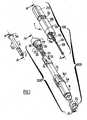
- FIG. 1shows an exploded perspective view of a device for automatic injection according to an embodiment of the present invention and generally designated by reference number 1.
- the inventive device 1comprises a housing 300 comprised of an upper housing assembly 100 and a lower housing assembly 200 that may be connected to each other by means of a snap-fit connection 110, 210 (see, e.g., Figure 20 ), screw-type connection, bayonet connection, or other means of connecting two parts together, in an unreleasable way or not.
- the means for connecting the upper housing assembly 100 to the lower housing assembly 200are made unreachable to the user.
- a container 50such as, for example, a syringe, is received in at least one of the upper and lower housing assemblies 100, 200.
- the container 50is partially received in each of the upper and lower housing assemblies 100, 200, as discussed in more detail herein.
- the container 50has a flange 5a defined at an open proximal end, and an injection needle 6 (see, e.g., Figure 2 ) at a substantially closed distal end 5b.
- Lateral walls 5extend between the proximal and distal ends and define a reservoir 5c sized and shaped to contain a predetermined amount of a product 3 for injection.
- the injection needle 6may be fixed to the distal end 5b, or removable therefrom, as a matter of design choice.
- the injection needle 6is in fluid communication with the reservoir 5c and provides an outlet port of the container 50 for the product 3.
- a needle shield 2is provided at the distal end of the container 50 to cover and protect the needle 6 before use of the device 1.
- the needle shield 2also provides for a sealing means of the distal end of the container 50 before use.
- a piston 7is provided in the container 50 and which is movable within the reservoir 5c. Movement of the piston 7 causes the product 3 to be expelled from said container 50 through the injection needle 6 during the injection of the product 3 into the patient.
- the upper housing assembly 100has a generally cylindrically shaped outer sleeve 19 comprised of an inner cylinder 19a and an outer cylinder 19b, the cylinders 19a and 19b being linked to each other by at least a radial wall 16.
- the distal part of the inner cylinder 19ais provided on its outer wall with at least two flexible legs 20 protruding in the proximal direction and being capable of being radially deflected.
- the proximal end of the inner cylinder 19ais provided with two flexible teeth 21, capable of being radially deflected, and with an inner radial rim 34.
- the upper housing assembly 100further comprises a push button 23 received in the outer sleeve 19.
- the proximal end of the push button 23is closed by a transversal wall 23a which forms a pushing surface for the user to exert a manual pressure on said push button 23.
- the distal end 24 of the push button 23is open.
- the distal face of the transversal wall 23ais provided with two distal teeth 25.
- the plunger rod 28is provided at its distal end with a flange 28a and at its proximal end with a radial stop 29.
- the plunger rod 28is provided, in its proximal portion, with two radial projections 32, the function of which will be explained later.
- a first spring 30is provided between said plunger rod 28 and said inner cylinder 19a: The distal end of the spring 30 bears on the flange 28a of the plunger rod 28, and the proximal end of the spring 30 bears on the distal face of the inner radial rim 34 of the inner cylinder 19a.
- Spring 30causes displacement of the container 50 within at least one of the upper and lower housing assemblies 100, 200 from an initial position to an injection position, and further causes movement of the piston 7 within the container 50 to cause the product 3 to be expelled therefrom through the injection needle 6.
- the lower housing assembly 200comprises a housing 8 which receives, at least partially the container 50.
- the container 50is movable relative to said housing 8 between an initial position, in which a tip of the needle 6 does not extend beyond a distal end of the housing 8 (see, e.g., Figure 4 ), and an insertion position, distally spaced relative to said initial position and in which the tip of the needle 6 extends beyond the distal end of the housing 8 and is exposed over a predetermined length (see, e.g., Figure 11 ).
- the housing 8has a general cylindrical shape and is open at both ends.
- the housing 8has a distal part 8b and a proximal part 8a, the diameter of the proximal part 8a being greater than the diameter of the distal part 8b.
- the proximal part 8a and the distal part 8b of the housing 8are joined by a radial wall 8c.
- the proximal surface 9 of the radial wall 8cforms an abutment surface, the function of which will be explained later.
- the housing 8comprises two opposite windows 8d in its proximal part 8a.
- the lower housing assembly 200also includes a safety shield 10 that is at least partially received within the housing 8.
- a proximal part of the safety shield 10is provided on its outer wall with two opposite flexible tongues 12, capable of being radially deflected.
- the proximal part of the safety shield 10is also provided with two opposite first proximal teeth 13 and with two opposite second proximal teeth 14, distally spaced from said first proximal teeth 13.
- the safety shield 10is provided, on its inner wall, with a radial rim 35, distally spaced from said flexible tongues 12.
- the safety shield 10is coupled to the housing 8 and is able to move between a first position and a second position in which the tip of the needle does not extend beyond a distal end of the safety shield 10.
- the device 1 of the present inventionfurther comprises an inner ring 26 which receives part of the proximal portion of said container 50, the inner diameter of said inner ring 26 being less than the outer diameter of the flange 5a of said container 50 so as to prevent to container 50 from passing completely through the ring 26 when the ring 26 and container 50 are assembled together (see, e.g., Figure 3 ).
- the inner ring 26 and container 50may move together within the upper and lower housing assemblies 100, 200 as the container 50 is moved from its initial position to its insertion position (discussed in more detail below).
- the inner ring 26comprises at least two distal legs 27 and at least two outer radial rims 33, tangentially spaced from said two distal legs 27.
- the device 1 of the present inventionalso comprises an outer ring 17 which receives, at least partially, said inner ring 26.
- the outer ring 17is provided on its inner wall with at least two opposite radially flexible tongues 18 that extend in the proximal direction.
- a second spring 31is provided between said container 50 and said inner ring 26. As shown on Figure 2 , the distal end of the second spring 31 bears on the proximal face of the radial rim 35 of the safety shield 10, and the proximal end of said second spring 31 bears on a distal face of said inner ring 26.
- the device 1 of the present inventionis also provided with a deshielder 15 for removing the needle shield 2.
- the deshielder 15carries the needle shield 2.
- the deshielder 15is coupled to the needle shield 2.
- a userremoves the deshielder 15, which also removes the needle shield 2.
- the deshielder 15is provided with longitudinal grooves 40 and the distal region of the housing 8 is provided with longitudinal ribs 41.
- the grooves 40 and the ribs 41are aligned with the axis of the device so as to provide a single direction for the removal of the deshielder 15 coupled to the needle shield 2 (not shown), and so as to act as guiding means allowing only a sliding longitudinal translation of the deshielder/needle shield with respect to the housing 8 when said deshielder/needle shield is removed from the device 1.
- the distal end of the ribs 41are reduced so as to facilitate the alignment of the ribs 41 with the grooves 40.
- the needle shield 2can not be rotated before use, and the removal of the needle shield 2 can not be achieved with a rotational movement, thus reducing or eliminating the rotation of the rubber protection in which the needle 6 is embedded before use. This reduces or eliminates the risk of creating rubber particles due to the sharpness of the distal tip of the needle 6. In consequence, there is no generation of particles at the tip of the needle 6 and the quality of the injection to come is not impacted.
- the needle shield 2 and/or the deshielder 15may be equipped with ribs and the housing 8 is provided with grooves, said ribs and said grooves cooperating together to limit or avoid any rotational movement of the needle shield 2 when said needle shield is removed from the device 1.
- the number of ribsis equal or less than the number of grooves.
- the number of ribsshould be sufficient to lock in rotation the needle shield when attempted to be moved with a rotational movement by hand.
- the groovesmay be enlarged at their extremity, with a chamfer for instance, in order to facilitate said deshielder/needle shield to be assembled onto said housing for industrial purpose and to facilitate the assembly operation.
- the deshielder 15 and needle shield 2provide a way for a user of the device 1 to determine whether the device 1 has been tampered with prior to use.
- the deshielder 15 and needle shield 2provide an indication to the user when the deshielder 15 has been removed from the device 1 - that is, when it has been removed from the lower housing assembly 200.
- Figures 19b and 19cshow, respectively, the deshielder 15 coupled to the device 1 and the deshielder 15 removed from the device 1; the device 1 in Figure 19c being ready for use.
- the device 1 of the inventionmay contain sterile drugs and it is important to prove to end users that the container has not been tampered, and that the drug sterility has been maintained until the point of use.
- the present inventionadvantageously describes such a feature.
- the inventive device 1is provided to a user ready-to-use.
- the container 50is filled with a predetermined dose of an injectable product 3 - preferably a single dose thus providing a one-time use or disposable injection device.
- Multi-dose or reusable injection devicesare also contemplated by, and with the scope and spirit of the present invention.
- the userPrior to use, the user removes the deshielder 15 and the needle shield 2, without rotation of said needle shield 2, and places the device 1 against his/her skin at an injection site 4.
- the safety shield 10As the device 1 is pressed against the user's skin, the safety shield 10 is caused to move in the proximal direction and into the housing 8. Due to safety features of the inventive device 1, a user cannot activate the device 1 (i.e., cause the container 50 to move from its initial position to its injection position) until the safety shield 10 is caused to move a predetermined distance in the proximal direction. Indeed, the container 50 is in its passive state as long as the safety shield 10 has not moved out of its first position. With the device 10 pressed against his/her skin (and the safety shield 10 moved out of its first position in the proximal direction), the container 50 adopts its active state, and the user can activate the device 1 and begin an injection by pressing the push button 23.
- the inventive device 1causes the injectable product 3 to automatically be expelled from the container and into the user's skin.
- the device 1provides an audible indicator to the user of the status of the injection.
- the device 1may provide one or more audible clicks as the injection is being made - with the absence of a click indicating an end of the injection.
- a single clickmay indicate the end of the injection process. The audible clicks are made regardless of whether the user maintains pressure on the push button 23.
- the userremoves the device 1 from the injection site and the safety shield 10 is caused to automatically extend from the housing 8 (i.e., lower housing assembly 200) to cover the now-contaminated tip of the needle 6.
- the safety shield 10will automatically extend over the tip of the needle.
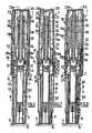
- FIG. 4 and 5is shown the device 1 before use, as provided to the user.
- the container 50is held in its initial position and the first spring 30 is held in a compressed condition by flexible teeth 21 of the inner cylinder 19a being engaged in the radial stop 29 of the plunger rod 28 and the flexible tongues 18 of the outer ring 17 being engaged in the radial rim 33 of the inner ring 26.
- the inner ring 26 and thus the container 50are thereby prevented from moving distally.
- the inner ring 26is also prevented from moving proximally by the proximal part 8a of the housing 8.
- the flexible tongues 12 of the safety shield 10are engaged on the abutment surface 9 of the housing 8.
- the first spring 30is in a pressurized or compressed condition, and the second spring 31 is in non-compressed or extended condition.
- the flange 5a of the containerbears on the inner ring 26.
- the container 50is therefore retained in its initial position by the combined actions of the flexible teeth 21 of the inner cylinder 19a, the radial stop 29 of the plunger rod 28 and the inner ring 26, which act as first retaining means of said container 50 in its initial position.
- the needle 6is protected by the needle shield 2 which is contained within the deshielder 15.
- the needle 6 and the needle shield 2are both received within the safety shield 10.
- the shape of the deshielderis such that it limits or prevents the needle shield to rotate around the needle.
- needle shieldsare made of rubber or elastomeric material.
- the sharp needle, embedded into the rubber shieldmay create a core of rubber if rotated when removed. Then, this rubber core, located into the needle internal diameter may then block the needle and prevent the drug to be injected or may be injected into the patient's skin together with the drug upon activation of the injection device.
- the push button 23is also in a passive state such that depression by a user on the pushing surface 23a will not cause the device 1 to make an injection.
- the push button 23is movable in the distal direction when the button 23 is in the passive state, it cannot cause activation of the device 1 because a distal end 24 of the push button 23 comes in contact with the proximal end of the flexible legs 20 of the inner cylinder 19a.
- the push button 23is therefore stopped and the device 1 can not be triggered or activated.
- the push button 23 and the container 50are both in their passive state.
- the device 1 of the inventionis therefore particularly safe, as it cannot be triggered through a single action (i.e., only by pressing on the push button 23).
- the triggering of the device 1 of the inventionrequires at least two steps.
- the push button 23, which acts as a deactivating means of the first retaining means of the first spring 30 in its compressed condition and of the container 50 in its initial positionmust previously be caused to pass from a passive state, in which the exercise of a manual pressure by the user on said push button 23 does not cause the release of said first retaining means, to an active state, in which the exercise of said manual pressure does cause the release of said first retaining means.
- movement of the safety shield 10 out of its first positioncauses the push button 23, and in consequence the container 50, to move from their passive state to their active state.
- This first stepis shown on Figures 6 and 7 .
- the userapplies the device 1 on the injection site 4 by means of the bearing surface 11 of the safety shield 10. He/she then exerts a distal force on the housing 8 thereby causing the safety shield 10 to move relative to said housing 8 from a first position, namely a rest position, shown on Figures 4 and 5 , for example, to an intermediate position, namely a bearing position, shown on Figures 6 and 7 - the bearing position being proximally spaced relative to said rest position.
- the first proximal teeth 13 of the safety shield 10contact the flexible legs 20 of the inner cylinder 19a and cause the flexible legs 20 to deflect radially towards the center of the device 1, as shown on Figure 8 .
- the flexible legs 20do not opposingly face the distal end 24 of the push button 23 and said push button 23 is now in its active state.
- Movement of the safety shield 10 from its rest position to its bearing positionalso places the container 50 in its active state.
- the second proximal teeth 14 of the safety shield 10contact the radially flexible tongues 18 of the outer ring 17 and cause the flexible tongues 18 to deflect radially thereby disengaging them from the radial rim 33 of the inner ring 26, in which they were engaged.
- the container 50is placed in its active state and able to move to its injection position.
- movement of the container 50 to its injection positiondoes not occur upon the release or deflection of the flexible tongues 18 because the inner ring 26 and container 50 are biased in the proximal direction by the second spring 31.
- the inner ring 26is also blocked in the proximal direction by the proximal part 8a of said housing 8.
- the push button 23is not coupled to said plunger rod 28 when the push button 23 is in its passive state.
- the push button 23is then allowed to move in its passive state but it is prevented to have any action with the plunger rod 28.
- the safety shield 10, or any other engaging meanscauses the plunger rod 28 to be coupled to the push button 23 which is then placed in its active state.
- the push button 23being now in its active state, the user can, in a second step, trigger the device 1 to start the automatic injection.
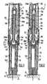
- the activation of the push button 23is shown on Figures 9 and 10 .
- the userexerts a manual pressure on the pushing surface 23a of the push button 23: the push button 23, which is no more stopped by the flexible legs 20, moves distally, thereby causing the distal movement of the teeth 25 of the push button 23.
- the teeth 25come in contact with the flexible teeth 21 of the inner cylinder 19a and cause said flexible teeth 21 to deflect radially and outwardly, as shown on Figure 10 .
- the flexible teeth 21are now disengaged from the radial stop 29 of the plunger rod 28 and the first spring 30 is now free to move from its compressed condition to an extended condition.
- the first spring 30expands and causes the plunger rod 28, which is coupled to said container 50, to move in the distal direction. Because of the previous disengagement of the flexible tongues 18 from the radial rim 33 of the inner ring 26, both the inner ring 26 and the container 50 are now free to move distally, i.e. the container 50 may move to its injection position.
- the first spring 30therefore pushes distally the plunger rod 28, the container 50 and the ring 26 as the container is caused to move to its injection position.
- Movement of the container 50 to its injection positionalso causes the needle 6 to pierce the user's skin at the injection site 4.
- the depth of insertion of the needle 6 into the user' skin at the injection site 4is controlled by the interaction between the distal legs 27 of said inner ring 26 and the abutment surface 9 of the housing 8, as shown on Figures 11 and 12 .
- the end of distal legs 27 engage abutment surface 9movement of the container 50 in the distal direction, and thus, injection of the needle 6 into the user's skin, is stopped.
- the needle 6is now inserted into the injection site 4 over a predetermined length, said predetermined length being controlled by the engagement of said distal legs 27 on said abutment surface 9, as shown on Figures 11 and 12 .
- the insertion depth of the needle 6could be controlled by the engagement of said distal legs 27 on an abutment surface provided on the safety shield 10.
- the insertion depthcould be variable, and/or controlled. While it may not be desirous to enable a user to vary the injection depth, such control may be desirable in the hands of a pharmaceutical company or supplier of the injection device 1 of the present invention. For example, different injection depths may be desired for different pharmaceutical compounds (i.e., injectable products). Depending upon the product 3 provided in the container 50, it may be necessary for the pharmaceutical company or other supply of the inventive device 1 to set the injection depth for each different compound. This may be accomplished by enabling the pharmaceutical company to control the spatial relationship between the distal legs 27 and abutment surface 9 - that relationship controlling the injection depth of the needle 6.
- the inner ring 26has moved distally and its distal legs 27 have come in contact with the flexible tongues 12 of the safety shield 10, causing the flexible tongues 12 to be deflected radially and inwardly, as shown on Figure 11 .
- the second spring 31has been caused to compress and has reached a pressurized or compressed condition, as shown on Figure 11 . Yet, the distal end of said second spring 31 bears on the radial rim 35 of said safety shield 10 which is maintained against the injection site 4 by the distal pressure exerted by the user on the device 1 and said second spring 31 is therefore not free to expand.
- the safety shield 10is movable to its second position. In consequence, in this position, the safety shield 10 automatically extends to its second position when a user removes the device 1 from the injection site 4 any time after the container 50 has been moved to its injection position.
- the device 1 of the inventionis therefore particularly safe and it prevents accidental needlestick injuries even in case said device 1 is removed from the injection site 4 before the injection of the product is actually completed.
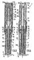
- the first spring 30still continues its expansion, overcomes the stiction of the piston 7 and the piston 7 is caused to move distally, realizing the injection of the product 3, as shown on Figures 13 and 14 .
- the injectionis therefore completed automatically without any manual operation from the user.
- the radial projections 32 provided on the plunger rod 28are in contact with said first spring 30 but they do not prevent the first spring 30 from extending in the distal direction. In consequence, each time the radial projections 32 touch a part of the first spring 30, for instance each time they touch a spire of the spring, they produce a sound.
- the first spring 30is stopped and by way of consequence, the sound also stops. The user is thereby informed that the injection is proceeding, and also when the injection is complete.
- the first spring 30 and the radial projections 32therefore constitute injection controlling means that produce an audible indicator as the product 3 is being expelled from the container 50, said audible indicator stopping when the piston 7 is proximate said distal end of the container 50 and the product 3 is substantially completely expelled from the container 50 thereby informing the user that injection of the product is completed.
- the radial projections 32are provided as part of the inner cylinder 19a.
- the radial projections 32therefore constitute good controlling means of the completion of the injection.
- the userknows when the product is being injected, and also when substantially all the product is injected, thereby preventing removal of the device 1 from the injection site 4 before the desire dose of the product 3 is injected.
- the userremoves the device 1 from the injection site 4, as shown in Figures 16 and 17 .
- removal of the device 1 from the injection site 4 any time after the container 50 is in its injection positionwill result in movement of the safety shield 10 to its second position in which it is locked over the needle 6 (i.e., the tip of the needle 6 does not extend beyond a distal end of the safety shield 10).
- Movement of the safety shield 10is effected by the second spring 31 as it returns to an extended condition upon removal of the device 1 from the injection site 4.
- Movement of the safety shield 10 out of its second positionis prevented by cooperating structural elements provided on the safety shield 10 and the inner ring 26, for example.
- the plunger rod 28is hollow and the first spring 30 is received within the hollow plunger rod 28.
- the present inventionenables springs of different force to be used in the inventive device 1 depending upon the particular requirements of the device 1.
- the needle 6 internal diametermay vary, or the viscosity of drugs contained in the reservoir 50 may also vary. These factors may increase significantly the injection duration, which can be very uncomfortable for the patient. To limit the injection duration in such cases, different spring forces may be required to accommodate different container configurations, and the present invention provides means for addressing such different configurations.
- the audible indicatormay comprise one or more projections provided on an inner wall of the hollow plunger rod 28.
- the first springpresents a variable diameter that engages a projection 32 only at or near the end of the injection.
- a kit 300comprised of an upper housing assembly 100 and a lower housing assembly 200. Details of each of the upper and lower housing assemblies 100, 200 have been described in detail above, and need not be described further.
- the kit 300may be provided to a pharmaceutical company, for example, together with a syringe (i.e., a container), for easy processing and assembly by the pharmaceutical company.
- the syringemay be provided as part of the kit 300, but it need not be - the kit 300 comprising the upper and lower housing assemblies 100, 200.
- the upper and lower housing assemblies 100, 200are connected to each other by connecting means 110, 210 provided on each of the assemblies 100, 200. Connecting means 110, 210 may be a snap-fit connection, screw-type connection, bayonet connection, or other means of connecting two parts together.
- Each of the upper and lower housing assemblies 100, 200may be provided on a tray 400, 500, each having a plurality of receptacles 410, 510 that each receives one of an upper and a lower housing assembly 100, 200.
- the receptacles 410, 510provide orientation for the housing assemblies 100, 200, further facilitating processing and assembly by the pharmaceutical company.
- a pharmaceutical companymay receive the kit 300 and place the kit 300 directly into their manufacturing process for filling (of the syringe) and assembly of the upper and lower housing assemblies 100, 200 with the syringe. Due to the orientation provided by the receptacles 410, 510, assembly of the syringe with the upper and lower housing assemblies 100, 200 is simple, quick, and easily fits within a pharmaceutical company's existing manufacturing processes.
- the device of the inventionis very easy to use and very safe.
- the injection device of the inventionthe generation of contaminating particles or dust in the area of the needle shield at the time the needle shield is removed from the injection device is avoided.
- the injection device of the inventionalso allows automatic injection of a product to be performed by a patient without any risk of needlestick injury, before, during and after use.
- the safety shield of the device of the inventionis in its active state right at the end of the insertion step, before the injection step actually begins. In this way, even if the patient decides to withdraw the device before the end of the injection, then the safety shield automatically extends over the needle.
- the device of the inventionallows the user to be informed of the compete injection of the product: this is particularly important when very precise doses of product must be injected. It is also a real benefit for the patient to be precisely informed of the end of the injection, since the end of the injection step is usually long with self-injectors, due to the fact that the spring that realizes the automatic injection slows its course down after a certain time.
Landscapes
- Health & Medical Sciences (AREA)
- Engineering & Computer Science (AREA)
- Heart & Thoracic Surgery (AREA)
- Vascular Medicine (AREA)
- Anesthesiology (AREA)
- Biomedical Technology (AREA)
- Hematology (AREA)
- Life Sciences & Earth Sciences (AREA)
- Animal Behavior & Ethology (AREA)
- General Health & Medical Sciences (AREA)
- Public Health (AREA)
- Veterinary Medicine (AREA)
- Environmental & Geological Engineering (AREA)
- Infusion, Injection, And Reservoir Apparatuses (AREA)
Description
- The present invention relates to a device for automatic injection of a product in a very safe way, especially for self-injection.
- In this application, the distal end of a component or of a device is to be understood as meaning the end furthest from the user's hand and the proximal end is to be understood as meaning the end closest to the user's hand. Likewise, in this application, the "distal direction" is to be understood as meaning the direction of injection, and the "proximal direction" is to be understood as meaning the opposite direction to the direction of injection.
- Some illnesses necessitate regular injections of drugs or products, for instance on a daily basis. In order to simplify the treatment, some self-injectors have been provided in order to allow the patient to perform the injection on its own.
- Of course, since the patient is usually neither a nurse nor an educated person in medical devices, such self-injectors must prove to be very simple to use and also very safe. In particular, the insertion of the needle must be performed at the right depth, the correct dose of product must be injected, that is to say a complete injection must be performed, and the injector must be deactivated after use before it is disposed of. Preferably, the needle should not be exposed, before and after use, in order to prevent any accidental needlestick injury.
- Document
WO 03/099358 Document GB 2 414 398 - The injection devices of the prior art are usually provided with needle shields that are made of rubber or elastomeric material. A drawback of these devices is that the sharp needle, embedded into the rubber shield may create a core of rubber if rotated when removed. Then, this rubber core, located into the needle internal diameter may then block the needle and prevent the drug to be injected or may be injected into the patient's skin together with the drug upon activation of the injection device.
- It would therefore be of interest to provide an injection device having an appropriate needle shield that does not jeopardize the quality of the injection when it is removed from the injection device before use.
- Another important requirement of these self-injection devices is that they must not be able to be activated inadvertently, before the patient is ready to perform the injection, and in particular before the device is correctly applied at the right injection site.
- Such self-injectors with automatic insertion and injection steps have been described in document
WO2005/044348 . The device described inWO2005/044348 comprises numerous complex elements and it is difficult to manufacture. Moreover, although the device described in this document comprises some safety means in order to cover the needle after use, this safety means are triggered by removal of the device from the injection site but only if the totality of the product has been injected. - In some cases though, the user may withdraw the self-injection device before the injection is completed. It is then of utmost importance that, in such a case, the safety be immediately triggered, although the injection is not completed. Otherwise, the patient may hurt himself or herself by accidental pricking or worse, he or she may reinsert the needle at a second injection site, and realize an inappropriate injection of the rest of the product.
- Moreover, it is also important that the user be informed that the totality of the product has been injected and that he may withdraw the device from the injection site.
- In consequence, there is a need for self-injection devices that would be easy to manufacture and assemble and for which the safety means would be automatically triggered by removal of the device from the injection site, even if the totality of the product has not been yet injected, and in which the needle would be efficiently protected before use by an appropriate needle shield, the removal of which would not jeopardize the quality of the injection to come.
- There is also a need for such a self-injection device that would clearly indicate to the user that the injection is completed.
- The present invention meets this need by proposing a device for automatic injection of a product into an injection site, said device comprising safety means automatically triggered by removal of the device from the injection site, even if the injection is not completed, said device also comprising a needle shield for protecting the needle before use of the device, the removal of said needle shield having no impact on the quality of the injection.
- The present invention relates to a device for automatic injection of a product into an injection site, the product being carried by a container having an open proximal end and a substantially closed distal end and having a reservoir defined therebetween, and a needle provided at the distal end and in fluid communication with the reservoir to provide an outlet port for the product from the container, and a piston provided in the container and movable with respect with the container, the movement of the piston causing the product to be expelled from the container through the needle, characterized in that said device comprises:
- a housing for the container, the container being movable relative to said housing between an initial position, in which a tip of the needle does not extend beyond a distal end of said housing and in which the container is in one of a passive state and an active state, to an insertion position, distally spaced relative to said initial position and in which the tip of the needle extends beyond said distal end of said housing, movement of the container out of its initial position being prevented when the container is in its passive state, and being permitted when the container is in its active state, and
- a safety shield coupled to said housing for movement between a first position and a second position in which the tip of the needle does not extend beyond a distal end of said safety shield, movement of said safety shield out of its first position placing the container in its active state, said safety shield being movable to its second position when the container is in said insertion position, said safety shield being secured against proximal movement when in said second position,
- a needle shield coupled with said housing and covering the needle prior to use of said device, removal of said needle shield from the device being with limited or no rotation of said needle shield.
- In the injection device of the invention, the generation of contaminating particles or dust in the area of the needle shield, before the needle shield is removed and at the time the needle shield is removed from the injection device, is avoided.
- In an embodiment of the invention, said needle shield and said housing are provided with guiding means designed to allow the longitudinal translation of the needle shield with respect to said housing while preventing its rotation, when said needle shield is removed from the device.
- Said guiding means may include at least one longitudinal groove provided on said needle shield or on said housing, and at least one longitudinal rib, provided respectively on said housing or on said needle shield, said rib being engaged in said groove and sliding within said groove when said needle shield is removed from the device.
- In another embodiment of the invention, said needle shield is coupled to a deshielder, part of said guiding means being provided on said deshielder.
- The device of the invention may further comprise:
- first biasing means coupled to said housing for biasing the container toward said insertion position, said first biasing means being in one of a compressed and an extended condition, and
- second biasing means coupled to said safety shield for biasing said safety shield toward its second position.
- The device of the invention may further comprise:
- first retaining means in said housing and arranged to maintain said first biasing means in its compressed condition,
- first deactivating means being activatable to release said first retaining means, said first deactivating means being in one of a passive state, in which said first deactivating means cannot cause the release of said first retaining means, and an active state, in which said first deactivating means can cause the release of said first retaining means, wherein movement of said safety shield out of its first position causes passage of said first deactivating means from its passive state to its active state.
- The device of the invention is perfectly safe. It is not possible to activate neither the insertion of the needle nor the injection without first applying the device on the injection site. Two steps are needed before starting the operation: first applying the device on the injection site, then exert a manual pressure on the first deactivating means. Exerting a manual pressure on the first deactivating means without applying the device on the injection site beforehand will not activate the insertion since the first deactivating means are then in a passive state.
- Moreover, in the injection assistance device of the invention, the safety shield is in its active state well before the end of the injection step.
- In a preferred embodiment of the invention, engaging means causes the passage of said safety shield from the passive state to the active state upon completion of insertion of the injection needle at the injection site, and prior to the product being totally expelled from said container through said injection needle.
- Therefore, the safety shield is in its active state right at the end of the insertion step, before the injection step actually begins. In this way, even if the patient decides to withdraw the device before the end of the injection, then the safety shield automatically extends over the needle and there is no risk of any accidental needlestick injury for the patient.
- The device of the invention may further comprise :
- second retaining means provided on at least one of said housing and said safety shield to prevent movement of said safety shield to its second position.
- In an embodiment of the invention said second retaining means comprises a flexible tongue and an abutment surface.
- The device of the invention may further comprise:
- first engaging means capable of releasing said second retaining means thereby enabling movement of said safety shield to its second position under the bias of said second biasing means.
- In an embodiment of the invention, said first engaging means comprises an inner ring coupled to the container and comprising a leg cooperating with said flexible tongue so as to disengage said flexible tongue from said abutment surface when the container moves to said insertion position.
- In an embodiment of the invention, said first deactivating means is a push button having a distal end, and said device further comprises:
- third retaining means, arranged to maintain said push button in its passive state, said third retaining means comprising a radially flexible leg provided on an outer sleeve, said outer sleeve being coupled to said housing, said distal end of said push button being blocked in axial and distal translation by said radially flexible leg,
- said safety shield further comprising a tooth that engages said third retaining means when said safety shield is moved out of its first position so as to deflect said radially flexible leg and enable passage of said push button from its passive state to its active state.
- The device of the invention may further comprise a plunger rod for causing the piston to move with respect to the container,
- said first retaining means comprising a flexible tooth, provided on one of said outer sleeve and said plunger rod, and engaged with a radial stop provided on one of said plunger rod and said outer sleeve,
- said push button comprising a tooth capable of cooperating with said flexible tooth so as to disengage said flexible tooth from said radial stop, under manual pressure exerted on said push button in its active state, thereby deactivating said first retaining means and causing the container to move from its initial position to its insertion position.
- The device of the invention may further comprise locking means arranged to prevent movement of said inner ring when said first deactivating means is in its passive state, said locking means being able to be unlocked through the movement of said safety shield out of its first position.
- In an embodiment of the invention, said first biasing means comprises automatic injection means, arranged in such a way as to cause said plunger rod to move said piston within the container when the container is in said insertion position, thereby causing the product to be automatically expelled from the container without any manual operation from the user.
- In an embodiment of the invention, said automatic injection means is disposed around said plunger rod.
- In another embodiment of the invention, said automatic injection means is disposed within said plunger rod.
- The device of the invention may further comprise injection controlling means to produce an audible indicator when the piston is proximate said distal end of the container and the product is substantially completely expelled from the container thereby informing the user that injection of the product is completed, said injection controlling means producing an audible indicator regardless of whether a user maintains pressure on said first deactivating means.
- The device of the invention may further comprise injection controlling means to produce an audible indicator as the product is being expelled from the container, said audible indicator stopping when the piston is proximate said distal end of the container and the product is substantially completely expelled from the container thereby informing the user that injection of the product is completed, said injection controlling means producing an audible indicator regardless of whether a user maintains pressure on said first deactivating means.
- In an embodiment of the invention said injection controlling means comprises :
- a plunger rod for causing the piston to move with respect to the container,
- first biasing means coupled to at least one of said housing and said plunger rod, said first biasing means being in one of a compressed and an extended condition, and
- means for interacting with said first biasing means to provide an injection status indication to a user of said device.
- Preferably, said means for interacting comprises a radial projection in contact with said first biasing means so as to produce an audible indication as said radial projection moves with respect to said biasing means.
- In an embodiment of the invention, said first biasing means and said second biasing means each comprise at least a spring.
- The device of the invention may further comprise tamper-evidence means removably coupled with said housing to shield said needle prior to use of said device, said tamper-evidence means being in one of a pre-use condition and a post-use condition, said post-use condition preventing re-use of said tamper evidence means with said device.
- Alternatively, said post-use condition preferably provides a visual indication that said tamper evidence means has been removed from said device.
- In an embodiment of the invention said tamper-evidence means comprises a deshielder coupled to said needle shield, said post-use condition proving an indication that said temper-evidence means has been removed from said device.
- In a kit for a device for automatic injection of a product into an injection site, the product being carried by a container having an open proximal end and a substantially closed distal end and having a reservoir defined therebetween, and a needle provided at the distal end and in fluid communication with the reservoir to provide an outlet port for the product from the container, and a piston provided in the container and movable with respect with the container, the movement of the piston causing the product to be expelled from the container through the needle, said kit comprises:
- a housing assembly comprising:
- an upper housing assembly,
- a lower housing assembly, at least one of said upper and said lower housing assembly being adapted to receive part of the container, the container being movable, when received within said at least one of said upper and said lower housing assembly, between an initial position, in which a tip of the needle does not extend beyond a distal end of said lower housing assembly and in which the container is in one of a passive state and an active state, to an insertion position, distally spaced relative to said initial position and in which the tip of the needle extends beyond said distal end of said lower housing assembly, movement of the container out of its first position being prevented when the container is in its passive state, and being permitted when the container is in its active state, and
- means for connecting said upper housing and said lower housing together, and
- a safety shield coupled to one of said upper and said lower housing assembly for movement between a first position and a second position in which the tip of the needle does not extend beyond a distal end of said safety shield, movement of said safety shield out of its first position placing the container in its active state, said safety shield being movable to its second position when the container is in said insertion position, said safety shield being secured against proximal movement when in said second position, and
- a needle shield coupled with one of said upper and said lower housing assembly and covering the needle prior to use of said device, removal of said needle shield being with limited or no rotation of said needle shield.
- The kit may further comprise means for carrying at least one of said upper housing assembly and said lower housing assembly, said carrying means carrying said one of said upper housing assembly and said lower housing assembly in a predetermined orientation.
- An automatic injection device is provided to a pharmaceutical company, for example, in condition for easy assembly and processing in the company's manufacturing processes. The upper and lower housing assemblies are each carried on a tray that provides orientation for the assemblies. In addition, the syringe (i.e., container) may be inserted into the housing assemblies without having to orient the syringe to either of the upper or lower assemblies. In a simple assembly process, the pharmaceutical company fills the syringe, inserts the syringe into one of the upper and lower housing assemblies, and connects the housing assemblies together.
- The device of the invention will now be further described in reference to the following description and attached drawings in which:
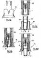
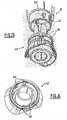
Figure 1 is an exploded perspective view of an embodiment of the device of the invention,Figure 2 is a longitudinal cross section view of the device ofFigure 1 , before use, with a needle shield and a deshielder, according to a longitudinal plane comprising the longitudinal axis AA' of thedevice 1, and passing through the middle ofwindow 8d,Figure 3 is a longitudinal cross section view, shifted of 90° compared tofigure 1 ,Figures 4 and 5 are longitudinal cross section views of the device ofFigure 1 , respectively corresponding toFigures 2 and 3 , in the initial position, after removal of the needle shield and the deshielder,Figures 6 to 8 are longitudinal cross section views of the device ofFigure 1 with the device placed against a user's skin at an injection site, whereinfigure 8 corresponds to a longitudinal cross section view shifted of 45° compared tofigure 6 ,Figures 9 and 10 are longitudinal cross section views of the device ofFigure 1 showing the activation of the first deactivating means,Figures 11 and 12 are longitudinal cross section views of the device ofFigure 1 with the container in its insertion position before injection,Figures 13 and 14 are longitudinal cross section views of the device ofFigure 1 at the end of the injection step,Figure 15 shows an alternate embodiment of an indicator for providing an injection status to the user,Figures 16 and 17 are longitudinal cross section views of the device ofFigure 1 with the safety shield in the extended position, after removal of the device from the injection site,Figure 18 shows an alternate embodiment of the device of the present invention with a hollow plunger rod and with the first spring disposed within the plunger rod,Figures 19a to 19d show a deshielder in accordance with the present invention that provides a tamper-evidence means to indicate to a user of the device that the deshielder has been removed from the device,Figure 20 is a perspective view of a kit comprising an upper housing assembly and a lower housing assembly,Figure 21 is a perspective view of a tray for carrying a plurality of lower housing assemblies in an oriented manner, andFigure 22 is a perspective view of a tray for carrying a plurality of upper housing assemblies in an oriented manner,Figure 23 is a perspective view of a deshielder of a device of the invention, said deshielder being coupled to a needle shield,Figure 24 is a perspective view from the top of the deshielder offigure 23 .- Referring now to the drawings, the present invention will now be described in detail.
Figure 1 shows an exploded perspective view of a device for automatic injection according to an embodiment of the present invention and generally designated byreference number 1. Theinventive device 1 comprises ahousing 300 comprised of anupper housing assembly 100 and alower housing assembly 200 that may be connected to each other by means of a snap-fit connection 110, 210 (see, e.g.,Figure 20 ), screw-type connection, bayonet connection, or other means of connecting two parts together, in an unreleasable way or not. When the device of the injection is of a single use type, the means for connecting theupper housing assembly 100 to thelower housing assembly 200 are made unreachable to the user. Acontainer 50 such as, for example, a syringe, is received in at least one of the upper andlower housing assemblies container 50 is partially received in each of the upper andlower housing assemblies container 50 has aflange 5a defined at an open proximal end, and an injection needle 6 (see, e.g.,Figure 2 ) at a substantially closed distal end 5b.Lateral walls 5 extend between the proximal and distal ends and define areservoir 5c sized and shaped to contain a predetermined amount of aproduct 3 for injection. Theinjection needle 6 may be fixed to the distal end 5b, or removable therefrom, as a matter of design choice. Theinjection needle 6 is in fluid communication with thereservoir 5c and provides an outlet port of thecontainer 50 for theproduct 3. Aneedle shield 2 is provided at the distal end of thecontainer 50 to cover and protect theneedle 6 before use of thedevice 1. Theneedle shield 2 also provides for a sealing means of the distal end of thecontainer 50 before use. Apiston 7 is provided in thecontainer 50 and which is movable within thereservoir 5c. Movement of thepiston 7 causes theproduct 3 to be expelled from saidcontainer 50 through theinjection needle 6 during the injection of theproduct 3 into the patient. - With reference to
Figures 1-3 , theupper housing assembly 100 of thedevice 1 of the present invention will now be described in further detail. Theupper housing assembly 100 has a generally cylindrically shapedouter sleeve 19 comprised of aninner cylinder 19a and anouter cylinder 19b, thecylinders radial wall 16. The distal part of theinner cylinder 19a is provided on its outer wall with at least twoflexible legs 20 protruding in the proximal direction and being capable of being radially deflected. The proximal end of theinner cylinder 19a is provided with twoflexible teeth 21, capable of being radially deflected, and with an innerradial rim 34. - The
upper housing assembly 100 further comprises apush button 23 received in theouter sleeve 19. The proximal end of thepush button 23 is closed by atransversal wall 23a which forms a pushing surface for the user to exert a manual pressure on saidpush button 23. Thedistal end 24 of thepush button 23 is open. The distal face of thetransversal wall 23a is provided with twodistal teeth 25. - A
plunger rod 28 for causing saidpiston 7 to move with respect to saidcontainer 50, as will be explained later, is received within theinner cylinder 19a of saidouter sleeve 19 of theupper housing assembly 100. Theplunger rod 28 is provided at its distal end with aflange 28a and at its proximal end with aradial stop 29. Theplunger rod 28 is provided, in its proximal portion, with tworadial projections 32, the function of which will be explained later. - A
first spring 30 is provided between saidplunger rod 28 and saidinner cylinder 19a: The distal end of thespring 30 bears on theflange 28a of theplunger rod 28, and the proximal end of thespring 30 bears on the distal face of the innerradial rim 34 of theinner cylinder 19a.Spring 30 causes displacement of thecontainer 50 within at least one of the upper andlower housing assemblies piston 7 within thecontainer 50 to cause theproduct 3 to be expelled therefrom through theinjection needle 6. - With continued reference to
Figures 1-3 , thelower housing assembly 200 of thedevice 1 of the present invention will now be described in further detail. Thelower housing assembly 200 comprises ahousing 8 which receives, at least partially thecontainer 50. As will appear later, thecontainer 50 is movable relative to saidhousing 8 between an initial position, in which a tip of theneedle 6 does not extend beyond a distal end of the housing 8 (see, e.g.,Figure 4 ), and an insertion position, distally spaced relative to said initial position and in which the tip of theneedle 6 extends beyond the distal end of thehousing 8 and is exposed over a predetermined length (see, e.g.,Figure 11 ). - The
housing 8 has a general cylindrical shape and is open at both ends. Thehousing 8 has a distal part 8b and aproximal part 8a, the diameter of theproximal part 8a being greater than the diameter of the distal part 8b. Theproximal part 8a and the distal part 8b of thehousing 8 are joined by aradial wall 8c. Theproximal surface 9 of theradial wall 8c forms an abutment surface, the function of which will be explained later. Thehousing 8 comprises twoopposite windows 8d in itsproximal part 8a. - The
lower housing assembly 200 also includes asafety shield 10 that is at least partially received within thehousing 8. A proximal part of thesafety shield 10 is provided on its outer wall with two oppositeflexible tongues 12, capable of being radially deflected. The proximal part of thesafety shield 10 is also provided with two opposite firstproximal teeth 13 and with two opposite secondproximal teeth 14, distally spaced from said firstproximal teeth 13. Thesafety shield 10 is provided, on its inner wall, with aradial rim 35, distally spaced from saidflexible tongues 12. - The
safety shield 10 is coupled to thehousing 8 and is able to move between a first position and a second position in which the tip of the needle does not extend beyond a distal end of thesafety shield 10. - The
device 1 of the present invention further comprises aninner ring 26 which receives part of the proximal portion of saidcontainer 50, the inner diameter of saidinner ring 26 being less than the outer diameter of theflange 5a of saidcontainer 50 so as to prevent tocontainer 50 from passing completely through thering 26 when thering 26 andcontainer 50 are assembled together (see, e.g.,Figure 3 ). When assembled together, theinner ring 26 andcontainer 50 may move together within the upper andlower housing assemblies container 50 is moved from its initial position to its insertion position (discussed in more detail below). Theinner ring 26 comprises at least twodistal legs 27 and at least two outerradial rims 33, tangentially spaced from said twodistal legs 27. - The
device 1 of the present invention also comprises anouter ring 17 which receives, at least partially, saidinner ring 26. Theouter ring 17 is provided on its inner wall with at least two opposite radiallyflexible tongues 18 that extend in the proximal direction. - A
second spring 31 is provided between saidcontainer 50 and saidinner ring 26. As shown onFigure 2 , the distal end of thesecond spring 31 bears on the proximal face of theradial rim 35 of thesafety shield 10, and the proximal end of saidsecond spring 31 bears on a distal face of saidinner ring 26. - The
device 1 of the present invention is also provided with adeshielder 15 for removing theneedle shield 2. As shown inFigures 19a-19d , thedeshielder 15 carries theneedle shield 2. Thedeshielder 15 is coupled to theneedle shield 2. Prior to use of thedevice 1, a user removes thedeshielder 15, which also removes theneedle shield 2. - As shown on
figures 23 and 24 , thedeshielder 15 is provided withlongitudinal grooves 40 and the distal region of thehousing 8 is provided withlongitudinal ribs 41. Thegrooves 40 and theribs 41 are aligned with the axis of the device so as to provide a single direction for the removal of thedeshielder 15 coupled to the needle shield 2 (not shown), and so as to act as guiding means allowing only a sliding longitudinal translation of the deshielder/needle shield with respect to thehousing 8 when said deshielder/needle shield is removed from thedevice 1. As can be seen fromfigure 23 , the distal end of theribs 41 are reduced so as to facilitate the alignment of theribs 41 with thegrooves 40. Because of the specific features of thedeshielder 15, theneedle shield 2 can not be rotated before use, and the removal of theneedle shield 2 can not be achieved with a rotational movement, thus reducing or eliminating the rotation of the rubber protection in which theneedle 6 is embedded before use. This reduces or eliminates the risk of creating rubber particles due to the sharpness of the distal tip of theneedle 6. In consequence, there is no generation of particles at the tip of theneedle 6 and the quality of the injection to come is not impacted. - In another embodiment of the invention, not shown, the
needle shield 2 and/or thedeshielder 15 may be equipped with ribs and thehousing 8 is provided with grooves, said ribs and said grooves cooperating together to limit or avoid any rotational movement of theneedle shield 2 when said needle shield is removed from thedevice 1. - In an embodiment of the invention, the number of ribs is equal or less than the number of grooves. The number of ribs should be sufficient to lock in rotation the needle shield when attempted to be moved with a rotational movement by hand.
- In another embodiment, not shown, the grooves may be enlarged at their extremity, with a chamfer for instance, in order to facilitate said deshielder/needle shield to be assembled onto said housing for industrial purpose and to facilitate the assembly operation.
- In one embodiment of the present invention, the
deshielder 15 andneedle shield 2 provide a way for a user of thedevice 1 to determine whether thedevice 1 has been tampered with prior to use. Generally stated, thedeshielder 15 andneedle shield 2 provide an indication to the user when thedeshielder 15 has been removed from the device 1 - that is, when it has been removed from thelower housing assembly 200.Figures 19b and 19c show, respectively, thedeshielder 15 coupled to thedevice 1 and thedeshielder 15 removed from thedevice 1; thedevice 1 inFigure 19c being ready for use. - Once the
deshielder 15 that carries theneedle shield 2 has been removed, it cannot be placed back onto thedevice 1, that is ontolower housing assembly 200, without generating a backward shift of theneedle shield 2 versus thedeshielder 15. Thedevice 1 of the invention may contain sterile drugs and it is important to prove to end users that the container has not been tampered, and that the drug sterility has been maintained until the point of use. The present invention advantageously describes such a feature. - The functioning of the
device 1 will now be explained in reference toFigures 4-18 . Before providing a detailed description of the operation of adevice 1 constructed in accordance with the present invention, the following general description of its operation is provided. Theinventive device 1 is provided to a user ready-to-use. Thecontainer 50 is filled with a predetermined dose of an injectable product 3 - preferably a single dose thus providing a one-time use or disposable injection device. Multi-dose or reusable injection devices are also contemplated by, and with the scope and spirit of the present invention. Prior to use, the user removes thedeshielder 15 and theneedle shield 2, without rotation of saidneedle shield 2, and places thedevice 1 against his/her skin at an injection site 4. As thedevice 1 is pressed against the user's skin, thesafety shield 10 is caused to move in the proximal direction and into thehousing 8. Due to safety features of theinventive device 1, a user cannot activate the device 1 (i.e., cause thecontainer 50 to move from its initial position to its injection position) until thesafety shield 10 is caused to move a predetermined distance in the proximal direction. Indeed, thecontainer 50 is in its passive state as long as thesafety shield 10 has not moved out of its first position. With thedevice 10 pressed against his/her skin (and thesafety shield 10 moved out of its first position in the proximal direction), thecontainer 50 adopts its active state, and the user can activate thedevice 1 and begin an injection by pressing thepush button 23. That will cause thecontainer 50 to move from its initial position to its injection position, which also causes theneedle 6 to pierce the user's skin. In addition, by pressing thepush button 23 once, theinventive device 1 causes theinjectable product 3 to automatically be expelled from the container and into the user's skin. While the injection is being made or at the end of the injection process, thedevice 1 provides an audible indicator to the user of the status of the injection. For example, thedevice 1 may provide one or more audible clicks as the injection is being made - with the absence of a click indicating an end of the injection. In another example, a single click may indicate the end of the injection process. The audible clicks are made regardless of whether the user maintains pressure on thepush button 23. Once the injection is complete, the user removes thedevice 1 from the injection site and thesafety shield 10 is caused to automatically extend from the housing 8 (i.e., lower housing assembly 200) to cover the now-contaminated tip of theneedle 6. Advantageously, even if the user removes thedevice 1 from the injection site 4 before the injection is complete, thesafety shield 10 will automatically extend over the tip of the needle. Once thedevice 1 is removed from the injection site 4 and theshield 10 is extended over the tip of theneedle 6, theshield 10 locks in place and cannot thereafter be moved from its locked position in the proximal direction to expose the tip of theneedle 6. The useddevice 1 is thus rendered safe for handling and disposal. - On
Figures 4 and 5 is shown thedevice 1 before use, as provided to the user. As shown onFigure 3 , thecontainer 50 is held in its initial position and thefirst spring 30 is held in a compressed condition byflexible teeth 21 of theinner cylinder 19a being engaged in theradial stop 29 of theplunger rod 28 and theflexible tongues 18 of theouter ring 17 being engaged in theradial rim 33 of theinner ring 26. Theinner ring 26 and thus thecontainer 50 are thereby prevented from moving distally. Theinner ring 26 is also prevented from moving proximally by theproximal part 8a of thehousing 8. - As shown on
Figure 2 , theflexible tongues 12 of thesafety shield 10 are engaged on theabutment surface 9 of thehousing 8. Thefirst spring 30 is in a pressurized or compressed condition, and thesecond spring 31 is in non-compressed or extended condition. - The
flange 5a of the container bears on theinner ring 26. Thecontainer 50 is therefore retained in its initial position by the combined actions of theflexible teeth 21 of theinner cylinder 19a, theradial stop 29 of theplunger rod 28 and theinner ring 26, which act as first retaining means of saidcontainer 50 in its initial position. - In this position, the
needle 6 is protected by theneedle shield 2 which is contained within thedeshielder 15. Theneedle 6 and theneedle shield 2 are both received within thesafety shield 10. - When the user decides to realize the injection, he/she first removes the deshielder 15: by this operation, he/she also removes the
needle shield 2, as shown onFigures 4 and 5 . - In the example shown on
figure 23 , the shape of the deshielder is such that it limits or prevents the needle shield to rotate around the needle. This is an advantage of the present invention as, usually, needle shields are made of rubber or elastomeric material. The sharp needle, embedded into the rubber shield may create a core of rubber if rotated when removed. Then, this rubber core, located into the needle internal diameter may then block the needle and prevent the drug to be injected or may be injected into the patient's skin together with the drug upon activation of the injection device. - As can be seen from
Figures 4 and 5 , after deshielding, thecontainer 50 is still retained in its initial position, and theneedle 6 is still protected by thesafety shield 10. On thesefigures 4 and 5 , thecontainer 50 is in its passive state. - In the position show non
Figures 2 to 5 , thepush button 23 is also in a passive state such that depression by a user on the pushingsurface 23a will not cause thedevice 1 to make an injection. Although thepush button 23 is movable in the distal direction when thebutton 23 is in the passive state, it cannot cause activation of thedevice 1 because adistal end 24 of thepush button 23 comes in contact with the proximal end of theflexible legs 20 of theinner cylinder 19a. Thepush button 23 is therefore stopped and thedevice 1 can not be triggered or activated. Thepush button 23 and thecontainer 50 are both in their passive state. Thedevice 1 of the invention is therefore particularly safe, as it cannot be triggered through a single action (i.e., only by pressing on the push button 23). - The triggering of the
device 1 of the invention requires at least two steps. In a first step, thepush button 23, which acts as a deactivating means of the first retaining means of thefirst spring 30 in its compressed condition and of thecontainer 50 in its initial position, must previously be caused to pass from a passive state, in which the exercise of a manual pressure by the user on saidpush button 23 does not cause the release of said first retaining means, to an active state, in which the exercise of said manual pressure does cause the release of said first retaining means. As discussed in more detail below, movement of thesafety shield 10 out of its first position causes thepush button 23, and in consequence thecontainer 50, to move from their passive state to their active state. - This first step is shown on
Figures 6 and 7 . In this first step, the user applies thedevice 1 on the injection site 4 by means of the bearingsurface 11 of thesafety shield 10. He/she then exerts a distal force on thehousing 8 thereby causing thesafety shield 10 to move relative to saidhousing 8 from a first position, namely a rest position, shown onFigures 4 and 5 , for example, to an intermediate position, namely a bearing position, shown onFigures 6 and 7 - the bearing position being proximally spaced relative to said rest position. During this movement, the firstproximal teeth 13 of thesafety shield 10 contact theflexible legs 20 of theinner cylinder 19a and cause theflexible legs 20 to deflect radially towards the center of thedevice 1, as shown onFigure 8 . Once deflected as just described, theflexible legs 20 do not opposingly face thedistal end 24 of thepush button 23 and saidpush button 23 is now in its active state. - Movement of the
safety shield 10 from its rest position to its bearing position also places thecontainer 50 in its active state. During such movement of thesafety shield 10, the secondproximal teeth 14 of thesafety shield 10 contact the radiallyflexible tongues 18 of theouter ring 17 and cause theflexible tongues 18 to deflect radially thereby disengaging them from theradial rim 33 of theinner ring 26, in which they were engaged. Upon such deflection, thecontainer 50 is placed in its active state and able to move to its injection position. However, movement of thecontainer 50 to its injection position does not occur upon the release or deflection of theflexible tongues 18 because theinner ring 26 andcontainer 50 are biased in the proximal direction by thesecond spring 31. Moreover, theinner ring 26 is also blocked in the proximal direction by theproximal part 8a of saidhousing 8. As a consequence, during this first step, although thecontainer 50 is able to move in the distal direction, it does not and is retained in its initial position. Actually, thecontainer 50 is retained in its initial position, but now in its active state, so that movement of the container out of its initial position may now be permitted, although only upon pressing of thepush button 23. - In an alternative embodiment of the invention, the
push button 23 is not coupled to saidplunger rod 28 when thepush button 23 is in its passive state. Thepush button 23 is then allowed to move in its passive state but it is prevented to have any action with theplunger rod 28. After application of thedevice 1 on the injection site 4, thesafety shield 10, or any other engaging means, causes theplunger rod 28 to be coupled to thepush button 23 which is then placed in its active state. - The
push button 23 being now in its active state, the user can, in a second step, trigger thedevice 1 to start the automatic injection. The activation of thepush button 23 is shown onFigures 9 and 10 . The user exerts a manual pressure on the pushingsurface 23a of the push button 23: thepush button 23, which is no more stopped by theflexible legs 20, moves distally, thereby causing the distal movement of theteeth 25 of thepush button 23. During this movement, theteeth 25 come in contact with theflexible teeth 21 of theinner cylinder 19a and cause saidflexible teeth 21 to deflect radially and outwardly, as shown onFigure 10 . - The
flexible teeth 21 are now disengaged from theradial stop 29 of theplunger rod 28 and thefirst spring 30 is now free to move from its compressed condition to an extended condition. Thefirst spring 30 expands and causes theplunger rod 28, which is coupled to saidcontainer 50, to move in the distal direction. Because of the previous disengagement of theflexible tongues 18 from theradial rim 33 of theinner ring 26, both theinner ring 26 and thecontainer 50 are now free to move distally, i.e. thecontainer 50 may move to its injection position. Thefirst spring 30 therefore pushes distally theplunger rod 28, thecontainer 50 and thering 26 as the container is caused to move to its injection position. - Movement of the
container 50 to its injection position also causes theneedle 6 to pierce the user's skin at the injection site 4. The depth of insertion of theneedle 6 into the user' skin at the injection site 4 is controlled by the interaction between thedistal legs 27 of saidinner ring 26 and theabutment surface 9 of thehousing 8, as shown onFigures 11 and 12 . When the end ofdistal legs 27 engageabutment surface 9, movement of thecontainer 50 in the distal direction, and thus, injection of theneedle 6 into the user's skin, is stopped. Theneedle 6 is now inserted into the injection site 4 over a predetermined length, said predetermined length being controlled by the engagement of saiddistal legs 27 on saidabutment surface 9, as shown onFigures 11 and 12 . - In another embodiment of the invention, the insertion depth of the
needle 6 could be controlled by the engagement of saiddistal legs 27 on an abutment surface provided on thesafety shield 10. Alternatively, the insertion depth could be variable, and/or controlled. While it may not be desirous to enable a user to vary the injection depth, such control may be desirable in the hands of a pharmaceutical company or supplier of theinjection device 1 of the present invention. For example, different injection depths may be desired for different pharmaceutical compounds (i.e., injectable products). Depending upon theproduct 3 provided in thecontainer 50, it may be necessary for the pharmaceutical company or other supply of theinventive device 1 to set the injection depth for each different compound. This may be accomplished by enabling the pharmaceutical company to control the spatial relationship between thedistal legs 27 and abutment surface 9 - that relationship controlling the injection depth of theneedle 6. - During this insertion of the
needle 6, theinner ring 26 has moved distally and itsdistal legs 27 have come in contact with theflexible tongues 12 of thesafety shield 10, causing theflexible tongues 12 to be deflected radially and inwardly, as shown onFigure 11 . During this same distal movement of theinner ring 26, thesecond spring 31 has been caused to compress and has reached a pressurized or compressed condition, as shown onFigure 11 . Yet, the distal end of saidsecond spring 31 bears on theradial rim 35 of saidsafety shield 10 which is maintained against the injection site 4 by the distal pressure exerted by the user on thedevice 1 and saidsecond spring 31 is therefore not free to expand. - It can be seen from
Figure 11 that because of the now deflected state of theflexible tongues 12, theabutment surface 9 no longer be an obstacle to the distal movement of saidflexible tongues 12. Therefore, in the insertion position of the needle as shown onFigures 11 and 12 , removal of thedevice 1 from the injection site 4 by the user at this stage of the operation would cause thesafety shield 10 to be moved distally to its second position by thesecond spring 31 to cover and protect theneedle 6. When in the second position, thesafety shield 10 is locked against proximal movement thereby preventing unintended access to the contaminatedneedle 6. - As noted above, once the
container 50 is in its insertion position, thesafety shield 10 is movable to its second position. In consequence, in this position, thesafety shield 10 automatically extends to its second position when a user removes thedevice 1 from the injection site 4 any time after thecontainer 50 has been moved to its injection position. Thedevice 1 of the invention is therefore particularly safe and it prevents accidental needlestick injuries even in case saiddevice 1 is removed from the injection site 4 before the injection of the product is actually completed. - At the end of the insertion step, the force of the
first spring 30, which continues its expansion, overcomes the friction of theflange 28a of theplunger rod 28 against the inner wall of thecontainer 50, and the distal end of theplunger rod 28 comes in contact with thepiston 7 with which it becomes coupled at least in the distal direction. - The
first spring 30 still continues its expansion, overcomes the stiction of thepiston 7 and thepiston 7 is caused to move distally, realizing the injection of theproduct 3, as shown onFigures 13 and 14 . The injection is therefore completed automatically without any manual operation from the user. - The
radial projections 32 provided on theplunger rod 28 are in contact with saidfirst spring 30 but they do not prevent thefirst spring 30 from extending in the distal direction. In consequence, each time theradial projections 32 touch a part of thefirst spring 30, for instance each time they touch a spire of the spring, they produce a sound. Of course, when thepiston 7 is proximate to the distal end of thecontainer 50 and theproduct 3 is substantially completely expelled from saidcontainer 50, thefirst spring 30 is stopped and by way of consequence, the sound also stops. The user is thereby informed that the injection is proceeding, and also when the injection is complete. - The
first spring 30 and theradial projections 32 therefore constitute injection controlling means that produce an audible indicator as theproduct 3 is being expelled from thecontainer 50, said audible indicator stopping when thepiston 7 is proximate said distal end of thecontainer 50 and theproduct 3 is substantially completely expelled from thecontainer 50 thereby informing the user that injection of the product is completed. - In an alternative embodiment shown in
Figure 15 , theradial projections 32 are provided as part of theinner cylinder 19a. - The
radial projections 32 therefore constitute good controlling means of the completion of the injection. The user knows when the product is being injected, and also when substantially all the product is injected, thereby preventing removal of thedevice 1 from the injection site 4 before the desire dose of theproduct 3 is injected. - When the injection is completed, the user removes the
device 1 from the injection site 4, as shown inFigures 16 and 17 . As noted above, removal of thedevice 1 from the injection site 4 any time after thecontainer 50 is in its injection position will result in movement of thesafety shield 10 to its second position in which it is locked over the needle 6 (i.e., the tip of theneedle 6 does not extend beyond a distal end of the safety shield 10). Movement of thesafety shield 10 is effected by thesecond spring 31 as it returns to an extended condition upon removal of thedevice 1 from the injection site 4. - Movement of the
safety shield 10 out of its second position is prevented by cooperating structural elements provided on thesafety shield 10 and theinner ring 26, for example. - In an alternative embodiment of the invention shown in
Figure 18 , theplunger rod 28 is hollow and thefirst spring 30 is received within thehollow plunger rod 28. By providing an option of locating thefirst spring 30 either inside or outside of theplunger rod 28, the present invention enables springs of different force to be used in theinventive device 1 depending upon the particular requirements of thedevice 1. For example, theneedle 6 internal diameter may vary, or the viscosity of drugs contained in thereservoir 50 may also vary. These factors may increase significantly the injection duration, which can be very uncomfortable for the patient. To limit the injection duration in such cases, different spring forces may be required to accommodate different container configurations, and the present invention provides means for addressing such different configurations. - In the embodiment shown in
Figure 18 , the audible indicator may comprise one or more projections provided on an inner wall of thehollow plunger rod 28. - Alternatively, it is possible to produce an audible indicator at the end of the injection: in such a case, for instance, the first spring presents a variable diameter that engages a
projection 32 only at or near the end of the injection. - Referring next to
Figures 20-22 , a kit will now be described in further detail. Akit 300 comprised of anupper housing assembly 100 and alower housing assembly 200. Details of each of the upper andlower housing assemblies kit 300 may be provided to a pharmaceutical company, for example, together with a syringe (i.e., a container), for easy processing and assembly by the pharmaceutical company. The syringe may be provided as part of thekit 300, but it need not be - thekit 300 comprising the upper andlower housing assemblies lower housing assemblies means assemblies - Each of the upper and
lower housing assemblies tray receptacles lower housing assembly receptacles housing assemblies kit 300 and place thekit 300 directly into their manufacturing process for filling (of the syringe) and assembly of the upper andlower housing assemblies receptacles lower housing assemblies - The device of the invention is very easy to use and very safe. In particular, with the injection device of the invention, the generation of contaminating particles or dust in the area of the needle shield at the time the needle shield is removed from the injection device is avoided.
- The injection device of the invention also allows automatic injection of a product to be performed by a patient without any risk of needlestick injury, before, during and after use. In particular, the safety shield of the device of the invention is in its active state right at the end of the insertion step, before the injection step actually begins. In this way, even if the patient decides to withdraw the device before the end of the injection, then the safety shield automatically extends over the needle. Moreover, the device of the invention allows the user to be informed of the compete injection of the product: this is particularly important when very precise doses of product must be injected. It is also a real benefit for the patient to be precisely informed of the end of the injection, since the end of the injection step is usually long with self-injectors, due to the fact that the spring that realizes the automatic injection slows its course down after a certain time.
Claims (21)
- A device (1) for automatic injection of a product (3) into an injection site (4), the product (3) being carried by a container (50) having an open proximal end and a substantially closed distal end and having a reservoir defined therebetween, and a needle (6) provided at the distal end and in fluid communication with the reservoir to provide an outlet port for the product (3) from the container, and a piston (7) provided in the container and movable with respect with the container, the movement of the piston causing the product to be expelled from the container through the needle, said device comprises:- a housing (8), having a general cylindrical shape, for the container, the container being movable relative to said housing between an initial position, in which a tip of the needle does not extend beyond a distal end of said housing and in which the container is in one of a passive state and an active state, to an insertion position, distally spaced relative to said initial position and in which the tip of the needle extends beyond said distal end of said housing, movement of the container out of its initial position being prevented when the container is in its passive state, and being permitted when the container is in its active state, and- a safety shield (10) coupled to said housing (8) for movement between a first position and a second position in which the tip of the needle does not extend beyond a distal end of said safety shield, movement of said safety shield (10) out of its first position placing the container (50) in its active state, said safety shield (10) being movable to its second position when the container (50) is in said insertion position, said safety shield (10) being secured against proximal movement when in said second position,- a needle shield (2) coupled with said housing (8) and covering the needle (6) prior to use of said device, said needle shield (2) being coupled to a deshielder (15),
characterized in that:said needle shield being made of rubber or elastomeric material in which the needle is embedded, removal of said needle shield (2) from the device is with limited or no rotation of said needle shield,said needle shield (2) and said housing (8) being provided with guiding means (40, 41) designed to allow the longitudinal translation of the needle shield (2) with respect to said housing (8) while preventing its rotation, when said needle shield (2) is removed from the device (1), part of said guiding means (40, 41) being provided on said deshielder (15). - Device according to claim 1,characterized in that said guiding means include at least one longitudinal groove (40) provided on said needle shield (2) or on said housing (8), and at least one longitudinal rib (41), provided respectively on said housing (8) or on said needle shield (2), said rib (41) being engaged in said groove (40) and sliding within said groove (40) when said needle shield (2) is removed from the device (1).
- Device according to claim 1,characterized in that said device further comprises:- first biasing means (30) coupled to said housing for biasing the container toward said insertion position, said first biasing means being in one of a compressed and an extended condition, and- second biasing means (31) coupled to said safety shield for biasing said safety shield toward its second position.
- Device according to claim 3,characterized in that said device further comprises:- first retaining means (21, 29) in said housing and arranged to maintain said first biasing means in its compressed condition,- first deactivating means (23) being activatable to release said first retaining means, said first deactivating mean being in one of a passive state, in which said first deactivating means cannot cause the release of said first retaining means, and an active state in which said first deactivating means can cause the release of said first retaining means, wherein movement of said safety shield out of its first position causes passage of said first deactivating means from its passive state to its active state.
- Device according to claim 4,characterized in that it further comprises:- second retaining means (9, 12) provided on at least one of said housing and said safety shield to prevent movement of said safety shield to its second position.
- Device according to claim 5, wherein said second retaining means comprises a flexible tongue (12) and an abutment surface (9).
- Device according to claims 5 and 6,characterized in that said device further comprises:- first engaging means (26, 27) capable of releasing said second retaining means thereby enabling movement of said safety shield to its second position under the bias of said second biasing means.
- Device according to claim 7, wherein said first engaging means comprises an inner ring (26) coupled to the container and comprising a leg (27) cooperating with said flexible tongue so as to disengage said flexible tongue from said abutment surface when the container moves to said insertion position.
- Device according to claim 4,characterized in that said first deactivating means is a push button (23) having a distal end (24), andin that said device further comprises:- third retaining means, arranged to maintain said push button in its passive state, said third retaining means comprising a radially flexible leg (20) provided on an outer sleeve (19), said outer sleeve being coupled to said housing, said distal end of said push button being blocked in axial and distal translation by said radially flexible leg (20),- said safety shield (10) further comprising a tooth (13) that engages said third retaining means when said safety shield is moved out of its first position so as to deflect said radially flexible leg and enable passage of said push button from its passive state to its active state.
- Device according to claim 9,characterized in that said device further comprises a plunger rod (28) for causing the piston to move with respect to the container,- said first retaining means comprising a flexible tooth (21), provided on one of said outer sleeve (19) and said plunger rod (28), and engaged with a radial stop (29) provided on one of said plunger rod and said outer sleeve,- said push button comprising a tooth (25) capable of cooperating with said flexible tooth so as to disengage said flexible tooth (21) from said radial stop, under manual pressure exerted on said push button in its active state, thereby deactivating said first retaining means and causing the container to move from its initial position to its insertion position.
- Device according to claim 8,characterized in that it further comprises locking means (18, 33) arranged to prevent movement of said inner ring (26) when said first deactivating means is in its passive state, said locking means being able to be unlocked through the movement of said safety shield (10) out of its first position.
- Device according to claim 9,characterized in that said first biasing means comprises automatic injection means (30), arranged in such a way as to cause said plunger rod to move said piston within the container when the container is in said insertion position, thereby causing the product (4) to be automatically expelled from the container without any manual operation from the user.
- Device according to claim 12, wherein said automatic injection means is disposed around said plunger rod.
- Device according to claim 12, wherein said automatic injection means is disposed within said plunger rod.
- Device according to any of claims 1 to 14,characterized in that it further comprises injection controlling means (30, 32) to produce an audible indicator when the piston is proximate said distal end of the container and the product is substantially completely expelled from the container thereby informing the user that injection of the product is completed, said injection controlling means (30, 32) producing an audible indicator regardless of whether a user maintains pressure on said first deactivating means (23).
- Device according to claim 15,characterized in that said injection controlling means (30, 32) comprises,- a plunger rod (28) for causing the piston to move with respect to the container,- first biasing means (30) coupled to at least one of said housing and said plunger rod, said first biasing means being in one of a compressed and an extended condition, and- means for interacting with said first biasing means to provide an injection status indication to a user of said device.
- Device according to claim 16,characterized in that said means for interacting comprises a radial projection (32) in contact with said first biasing means so as to produce an audible indication as said radial projection moves with respect to said biasing means.
- Device according to any of the preceding claims,characterized in that said first biasing means and said second biasing means each comprise at least a spring.
- Device according to claim 1,characterized in that said device further comprises tamper-evidence means removably coupled with said housing to shield said needle prior to use of said device, said tamper-evidence means being in one of a pre-use condition and a post-use condition, said post-use condition preventing re-use of said tamper evidence means with said device.
- Device according to claim 19,characterized in that said device further comprises tamper-evidence means removably coupled with said housing to shield said needle prior to use of said device, said tamper-evidence means being in one of a pre-use condition and a post-use condition, said post-use condition providing a visual indication that said tamper evidence means has been removed from said device.
- Device according to claim 19 or 20, wherein said tamper-evidence means comprises a deshielder (15) coupled to said needle shield (2), said post-use condition proving an indication that said temper-evidence means has been removed from said device.
Priority Applications (3)
| Application Number | Priority Date | Filing Date | Title |
|---|---|---|---|
| DK14199837.7TDK2921191T3 (en) | 2006-04-11 | 2007-04-11 | Automatic injection apparatus |
| EP14199837.7AEP2921191B1 (en) | 2006-04-11 | 2007-04-11 | Automatic injection device |
| EP17199825.5AEP3345638B1 (en) | 2006-04-11 | 2007-04-11 | Kit for an automatic injection device |
Applications Claiming Priority (2)
| Application Number | Priority Date | Filing Date | Title |
|---|---|---|---|
| FR0603200AFR2899482A1 (en) | 2006-04-11 | 2006-04-11 | Automatic medicament/product injection device for patient, has safety shield coupled to housing, and provided in active state at end of needle insertion step before which product/medicament injection step is not started |
| PCT/IB2007/002016WO2007132353A2 (en) | 2006-04-11 | 2007-04-11 | Automatic injection device |
Related Child Applications (4)
| Application Number | Title | Priority Date | Filing Date |
|---|---|---|---|
| EP14199837.7ADivisionEP2921191B1 (en) | 2006-04-11 | 2007-04-11 | Automatic injection device |
| EP14199837.7ADivision-IntoEP2921191B1 (en) | 2006-04-11 | 2007-04-11 | Automatic injection device |
| EP17199825.5ADivision-IntoEP3345638B1 (en) | 2006-04-11 | 2007-04-11 | Kit for an automatic injection device |
| EP17199825.5ADivisionEP3345638B1 (en) | 2006-04-11 | 2007-04-11 | Kit for an automatic injection device |
Publications (3)
| Publication Number | Publication Date |
|---|---|
| EP2007450A2 EP2007450A2 (en) | 2008-12-31 |
| EP2007450B1 EP2007450B1 (en) | 2014-12-24 |
| EP2007450B2true EP2007450B2 (en) | 2018-08-01 |
Family
ID=36942436
Family Applications (3)
| Application Number | Title | Priority Date | Filing Date |
|---|---|---|---|
| EP07735010.6AActiveEP2007450B2 (en) | 2006-04-11 | 2007-04-11 | Automatic injection device |
| EP17199825.5AActiveEP3345638B1 (en) | 2006-04-11 | 2007-04-11 | Kit for an automatic injection device |
| EP14199837.7AActiveEP2921191B1 (en) | 2006-04-11 | 2007-04-11 | Automatic injection device |
Family Applications After (2)
| Application Number | Title | Priority Date | Filing Date |
|---|---|---|---|
| EP17199825.5AActiveEP3345638B1 (en) | 2006-04-11 | 2007-04-11 | Kit for an automatic injection device |
| EP14199837.7AActiveEP2921191B1 (en) | 2006-04-11 | 2007-04-11 | Automatic injection device |
Country Status (9)
| Country | Link |
|---|---|
| US (1) | US7976499B2 (en) |
| EP (3) | EP2007450B2 (en) |
| JP (1) | JP5175838B2 (en) |
| CN (1) | CN101454032B (en) |
| DK (2) | DK2921191T3 (en) |
| ES (3) | ES2784426T3 (en) |
| FR (1) | FR2899482A1 (en) |
| HU (2) | HUE041887T2 (en) |
| WO (1) | WO2007132353A2 (en) |
Families Citing this family (183)
| Publication number | Priority date | Publication date | Assignee | Title |
|---|---|---|---|---|
| WO2003068290A2 (en) | 2002-02-11 | 2003-08-21 | Antares Pharma, Inc. | Intradermal injector |
| GB2410188B (en)* | 2004-01-23 | 2006-01-25 | Medical House Plc | Injection device |
| GB2414775B (en) | 2004-05-28 | 2008-05-21 | Cilag Ag Int | Releasable coupling and injection device |
| GB2414402B (en) | 2004-05-28 | 2009-04-22 | Cilag Ag Int | Injection device |
| GB2414400B (en) | 2004-05-28 | 2009-01-14 | Cilag Ag Int | Injection device |
| HUE042286T2 (en) | 2005-01-24 | 2019-06-28 | Antares Pharma Inc | Needle-filled pre-filled syringe |
| GB2427826B (en) | 2005-04-06 | 2010-08-25 | Cilag Ag Int | Injection device comprising a locking mechanism associated with integrally formed biasing means |
| GB2424836B (en) | 2005-04-06 | 2010-09-22 | Cilag Ag Int | Injection device (bayonet cap removal) |
| GB2425062B (en) | 2005-04-06 | 2010-07-21 | Cilag Ag Int | Injection device |
| PL1759729T3 (en) | 2005-08-30 | 2010-09-30 | Cilag Gmbh Int | Needle assembly for a prefilled syringe system |
| US20110098656A1 (en) | 2005-09-27 | 2011-04-28 | Burnell Rosie L | Auto-injection device with needle protecting cap having outer and inner sleeves |
| US20070173770A1 (en)* | 2006-01-23 | 2007-07-26 | The Medical House Plc | Injection device |
| GB0601309D0 (en) | 2006-01-23 | 2006-03-01 | Medical House The Plc | Injection device |
| WO2007131013A1 (en) | 2006-05-03 | 2007-11-15 | Antares Pharma, Inc. | Two-stage reconstituting injector |
| GB2438590B (en) | 2006-06-01 | 2011-02-09 | Cilag Gmbh Int | Injection device |
| GB2438593B (en) | 2006-06-01 | 2011-03-30 | Cilag Gmbh Int | Injection device (cap removal feature) |
| GB2438591B (en) | 2006-06-01 | 2011-07-13 | Cilag Gmbh Int | Injection device |
| WO2008047372A2 (en)* | 2006-10-19 | 2008-04-24 | Elcam Medical Agricultural Cooperative Association Ltd. | Automatic injection device |
| GB0625169D0 (en) | 2006-12-18 | 2007-01-24 | Medical House Plc The | Improved autoinjector |
| GB0704351D0 (en) | 2007-03-07 | 2007-04-11 | Medical House Plc The | Improved autoinjector |
| JP5264916B2 (en)* | 2007-09-25 | 2013-08-14 | ベクトン・ディキンソン・フランス・エス.エー.エス. | Automatic syringe with deactivating means movable by safety shield |
| WO2009040602A1 (en) | 2007-09-25 | 2009-04-02 | Becton Dickinson France | Autoinject0r with deactivating means moveable by a safety shield |
| EP2197522B1 (en) | 2007-10-05 | 2015-06-10 | Becton Dickinson France | Device for the automatic injection of a product in an injection site |
| GB0800103D0 (en)* | 2008-01-04 | 2008-02-13 | Owen Mumford Ltd | Sheath removver device |
| EP3636301A1 (en) | 2008-03-10 | 2020-04-15 | Antares Pharma, Inc. | Injector safety device |
| USD629510S1 (en)* | 2008-03-14 | 2010-12-21 | Becton, Dickinson And Company | Cap |
| CN103041478B (en) | 2008-04-10 | 2015-01-21 | 松下健康医疗控股株式会社 | Medication administering device |
| US8052645B2 (en) | 2008-07-23 | 2011-11-08 | Avant Medical Corp. | System and method for an injection using a syringe needle |
| CA3070618C (en) | 2008-05-20 | 2021-07-20 | Avant Medical Corp. | Autoinjector system |
| US8177749B2 (en)* | 2008-05-20 | 2012-05-15 | Avant Medical Corp. | Cassette for a hidden injection needle |
| GB2461086B (en) | 2008-06-19 | 2012-12-05 | Cilag Gmbh Int | Injection device |
| GB2461085B (en) | 2008-06-19 | 2012-08-29 | Cilag Gmbh Int | Injection device |
| GB2461084B (en) | 2008-06-19 | 2012-09-26 | Cilag Gmbh Int | Fluid transfer assembly |
| US8376993B2 (en) | 2008-08-05 | 2013-02-19 | Antares Pharma, Inc. | Multiple dosage injector |
| DE102008037310B4 (en) | 2008-08-11 | 2023-11-16 | Ypsomed Ag | Automatic injection device for administering a fixed dose |
| GB2463034B (en)* | 2008-08-28 | 2012-11-07 | Owen Mumford Ltd | Autoinjection devices |
| WO2010035056A1 (en)* | 2008-09-29 | 2010-04-01 | Becton Dickinson France | Automatic injection device with sensitive indicator of completed injection |
| CN103920212B (en)* | 2008-09-29 | 2017-04-12 | 贝克顿迪金森法国公司 | Automatic injecting device capable of giving sound indication when injection is completed |
| CN102209566B (en) | 2008-09-29 | 2014-03-26 | 贝克顿迪金森法国公司 | Automatic injection device |
| US8979807B2 (en)* | 2008-09-29 | 2015-03-17 | Becton Dickinson France | Automatic injection device with audible indicator of completed injection |
| US8876778B2 (en) | 2008-09-29 | 2014-11-04 | Becton Dickinson France | Injection device with retaining means actuated by needle shield |
| WO2010035057A1 (en)* | 2008-09-29 | 2010-04-01 | Becton Dickinson France | Autoinjector with audible indication of completed delivery |
| GB2465390A (en) | 2008-11-17 | 2010-05-19 | Owen Mumford Ltd | Syringe needle cover remover |
| GB0901801D0 (en)* | 2009-02-05 | 2009-03-11 | Medical House Plc The | Improved autoinjector |
| DE202009001836U1 (en)* | 2009-02-13 | 2009-05-20 | Dieter Hölzle Technik-Projekte GmbH | Electromechanical injection device |
| USD627459S1 (en)* | 2009-03-10 | 2010-11-16 | Nipro Corporation | Needle for medical purposes |
| JP5732039B2 (en) | 2009-03-20 | 2015-06-10 | アンタレス・ファーマ・インコーポレーテッド | Hazardous drug injection system |
| GB2469672B (en) | 2009-04-23 | 2013-09-25 | Medical House Ltd | Improved autoinjector |
| WO2010136078A1 (en)* | 2009-05-29 | 2010-12-02 | Tecpharma Licensing Ag | Injection device, especially auto-injector, comprising an anti-pricking mechanism and/or overload protection for a product container. |
| TWI393578B (en)* | 2009-07-07 | 2013-04-21 | Shl Group Ab | Injection device |
| EP2724739B1 (en) | 2009-07-30 | 2015-07-01 | Tandem Diabetes Care, Inc. | Portable infusion pump system |
| GB0913385D0 (en)* | 2009-07-31 | 2009-09-16 | Medical House The Plc | Improved autoinjector |
| JP5701889B2 (en) | 2009-10-08 | 2015-04-15 | エス・ホー・エル・グループ・アクチボラゲットShl Group Ab | Drug supply device |
| EP2490734B1 (en)* | 2009-10-23 | 2020-03-25 | Medicom Innovation Partner a/s | Auto injector with automatic needle shielding |
| TWI617334B (en)* | 2009-11-10 | 2018-03-11 | 瑞健集團股份有限公司 | Medicament delivery device |
| TWI569844B (en)* | 2009-11-10 | 2017-02-11 | 瑞健集團股份有限公司 | Medicament delivery device |
| DK2536452T3 (en) | 2010-02-18 | 2019-01-02 | Sanofi Aventis Deutschland | autoinjector |
| CA2790283A1 (en)* | 2010-02-22 | 2011-08-25 | Sanofi-Aventis Deutschland Gmbh | Force transmission arrangement for auto-injector |
| EP2583708B1 (en)* | 2010-03-31 | 2023-02-22 | SHL Medical AG | Medicament delivery device comprising feedback signalling means |
| EP2399635A1 (en) | 2010-06-28 | 2011-12-28 | Sanofi-Aventis Deutschland GmbH | Auto-injector |
| KR101834154B1 (en) | 2010-07-02 | 2018-03-05 | 사노피-아벤티스 도이칠란트 게엠베하 | Safety device for a pre-filled syringe and injection device |
| WO2012022810A2 (en)* | 2010-08-19 | 2012-02-23 | Novo Nordisk A/S | Medical injection device |
| EP2624882B1 (en) | 2010-10-06 | 2021-04-28 | Ypsomed AG | Locking and retaining mechanism for the needle guard sleeve of an injection device |
| EP2438939A1 (en)* | 2010-10-08 | 2012-04-11 | Sanofi-Aventis Deutschland GmbH | Arrangement for coupling a plunger to either a syringe or a stopper |
| EP2438942A1 (en)* | 2010-10-08 | 2012-04-11 | Sanofi-Aventis Deutschland GmbH | Auto-injector |
| GB201020472D0 (en)* | 2010-12-02 | 2011-01-19 | Oval Medical Technologies Ltd | A drive assembly for an autoinjector |
| EP2468340A1 (en) | 2010-12-21 | 2012-06-27 | Sanofi-Aventis Deutschland GmbH | Auto injector with an interlock switch detecting the position of the needle shroud |
| EP2468330A1 (en) | 2010-12-21 | 2012-06-27 | Sanofi-Aventis Deutschland GmbH | Auto-injector |
| EP2468342A1 (en)* | 2010-12-21 | 2012-06-27 | Sanofi-Aventis Deutschland GmbH | Front end for an auto-injector |
| EP2468339A1 (en) | 2010-12-21 | 2012-06-27 | Sanofi-Aventis Deutschland GmbH | Auto-injector |
| GB201021767D0 (en) | 2010-12-22 | 2011-02-02 | Owen Mumford Ltd | Autoinjectors |
| WO2012093075A1 (en)* | 2011-01-04 | 2012-07-12 | Sanofi-Aventis Deutschland Gmbh | Safety device for a pre-filled syringe and injection device |
| EP2661294B1 (en) | 2011-01-04 | 2020-08-26 | Sanofi-Aventis Deutschland GmbH | A safety device for a pre-filled syringe and an injection device |
| RU2580982C2 (en)* | 2011-01-04 | 2016-04-10 | Санофи-Авентис Дойчланд Гмбх | Protective devices for pre-filled syringe and injection device |
| GB2487235A (en)* | 2011-01-17 | 2012-07-18 | Owen Mumford Ltd | Injection device with pneumatic damping of the drive mechanism |
| ES2710905T3 (en) | 2011-01-24 | 2019-04-29 | E3D Agricultural Coop Association Ltd | Injector |
| EP2489386A1 (en) | 2011-02-18 | 2012-08-22 | Sanofi-Aventis Deutschland GmbH | Auto-injector |
| EP2489384A1 (en) | 2011-02-18 | 2012-08-22 | Sanofi-Aventis Deutschland GmbH | Auto-injector |
| EP2489387A1 (en) | 2011-02-18 | 2012-08-22 | Sanofi-Aventis Deutschland GmbH | Auto-injector |
| EP2489390A1 (en) | 2011-02-18 | 2012-08-22 | Sanofi-Aventis Deutschland GmbH | Detent mechanism |
| EP2489389A1 (en)* | 2011-02-18 | 2012-08-22 | Sanofi-Aventis Deutschland GmbH | Detent mechanism |
| EP2489388A1 (en) | 2011-02-18 | 2012-08-22 | Sanofi-Aventis Deutschland GmbH | Auto-injector |
| EP2489385A1 (en) | 2011-02-18 | 2012-08-22 | Sanofi-Aventis Deutschland GmbH | Auto-injector |
| EP2489381A1 (en) | 2011-02-18 | 2012-08-22 | Sanofi-Aventis Deutschland GmbH | Auto-injector |
| EP2489380A1 (en)* | 2011-02-18 | 2012-08-22 | Sanofi-Aventis Deutschland GmbH | Injection device |
| EP2489382A1 (en)* | 2011-02-18 | 2012-08-22 | Sanofi-Aventis Deutschland GmbH | Auto-injector |
| GB2488578B (en) | 2011-03-02 | 2017-05-24 | Owen Mumford Ltd | Injection device |
| GB2488579A (en) | 2011-03-02 | 2012-09-05 | Owen Mumford Ltd | Autoinjector with "injection complete" indicator |
| JP5922760B2 (en)* | 2011-04-05 | 2016-05-24 | エス・ホー・エル・グループ・アクチボラゲットShl Group Ab | Drug delivery device having locking mechanism with lever |
| EP2695630B1 (en)* | 2011-04-07 | 2022-01-19 | Terumo Kabushiki Kaisha | Liquid infusion instrument |
| PL2699293T3 (en) | 2011-04-20 | 2019-08-30 | Amgen Inc. | Autoinjector apparatus |
| US9220660B2 (en) | 2011-07-15 | 2015-12-29 | Antares Pharma, Inc. | Liquid-transfer adapter beveled spike |
| US8496619B2 (en) | 2011-07-15 | 2013-07-30 | Antares Pharma, Inc. | Injection device with cammed ram assembly |
| BR112014005465A2 (en) | 2011-09-09 | 2017-03-21 | Merck Patent Gmbh | autoinjector with separate needle injection |
| EP2596822A1 (en)* | 2011-11-24 | 2013-05-29 | Sanofi-Aventis Deutschland GmbH | Autoinjector |
| EP2606924A1 (en) | 2011-12-21 | 2013-06-26 | Sanofi-Aventis Deutschland GmbH | Autoinjector having a retracting syringe carrier |
| US9526838B2 (en)* | 2012-02-13 | 2016-12-27 | Sanofi-Aventis Deutschland Gmbh | Pen-type injection device and electronic clip-on module therefor |
| WO2013135566A2 (en)* | 2012-03-14 | 2013-09-19 | Carebay Europe Ltd | Medicament delivery device |
| EP4186545A1 (en) | 2012-04-06 | 2023-05-31 | Antares Pharma, Inc. | Needle assisted jet injection administration of testosterone compositions |
| USD808010S1 (en) | 2012-04-20 | 2018-01-16 | Amgen Inc. | Injection device |
| USD898908S1 (en) | 2012-04-20 | 2020-10-13 | Amgen Inc. | Pharmaceutical product cassette for an injection device |
| US9364610B2 (en) | 2012-05-07 | 2016-06-14 | Antares Pharma, Inc. | Injection device with cammed ram assembly |
| US9180242B2 (en) | 2012-05-17 | 2015-11-10 | Tandem Diabetes Care, Inc. | Methods and devices for multiple fluid transfer |
| US9278179B2 (en)* | 2012-06-20 | 2016-03-08 | Safety Syringes, Inc. | Contact trigger release needle guard with elastic spring |
| WO2014037946A1 (en) | 2012-09-05 | 2014-03-13 | Elcam Medical Agricultural Cooperative Association Ltd. | Electronic auto-injection device |
| EP2898912B1 (en) | 2012-09-21 | 2022-10-26 | Terumo Kabushiki Kaisha | Drug administration instrument |
| CN104768593B (en)* | 2012-10-03 | 2017-08-15 | 卡贝欧洲有限公司 | drug delivery device |
| WO2014068098A1 (en) | 2012-11-02 | 2014-05-08 | Novo Nordisk A/S | Drug delivery device with shield operated needle actuator |
| EP2727617A1 (en) | 2012-11-06 | 2014-05-07 | Sanofi-Aventis Deutschland GmbH | Autoinjector |
| BR112015010607A2 (en) | 2012-11-09 | 2017-12-05 | Iinjec Tech Inc | fluid delivery injector, retractable needle assembly, and method for injecting at least one dose of a transcutaneously fluid medication into the body. |
| CN104968380B (en) | 2013-01-29 | 2018-08-21 | 赛诺菲-安万特德国有限公司 | Assemblies for detecting plunger position |
| FI3659647T3 (en) | 2013-02-11 | 2024-03-28 | Antares Pharma Inc | NEEDLE-ASSISTED SPRAY INJECTOR WITH REDUCED TRIGGER FORCE |
| CA2905031C (en) | 2013-03-11 | 2018-01-23 | Hans PFLAUMER | Dosage injector with pinion system |
| EP2968773B1 (en) | 2013-03-13 | 2020-05-06 | Antares Pharma, Inc. | Push button safety injector |
| US9173998B2 (en) | 2013-03-14 | 2015-11-03 | Tandem Diabetes Care, Inc. | System and method for detecting occlusions in an infusion pump |
| ES2973257T3 (en) | 2013-03-15 | 2024-06-19 | Amgen Inc | Drug cassette, autoinjector and autoinjector system |
| CA2904661C (en) | 2013-03-15 | 2022-03-15 | Amgen Inc. | Drug cassette, autoinjector, and autoinjector system |
| EP3590568A1 (en) | 2013-03-22 | 2020-01-08 | TecPharma Licensing AG | Substance dispensing device with a signalling device |
| GB2517896B (en) | 2013-06-11 | 2015-07-08 | Cilag Gmbh Int | Injection device |
| GB2515038A (en)* | 2013-06-11 | 2014-12-17 | Cilag Gmbh Int | Injection device |
| GB2515039B (en) | 2013-06-11 | 2015-05-27 | Cilag Gmbh Int | Injection Device |
| GB2515032A (en) | 2013-06-11 | 2014-12-17 | Cilag Gmbh Int | Guide for an injection device |
| EP2823841A1 (en) | 2013-07-09 | 2015-01-14 | Sanofi-Aventis Deutschland GmbH | Autoinjector |
| EP2823840A1 (en) | 2013-07-09 | 2015-01-14 | Sanofi-Aventis Deutschland GmbH | Autoinjector |
| GB2516624B (en)* | 2013-07-25 | 2018-09-19 | Owen Mumford Ltd | Injection devices |
| CN105722539B (en) | 2013-11-13 | 2021-01-15 | 豪夫迈·罗氏有限公司 | Auxiliary manual injection device and method |
| JP5876464B2 (en)* | 2013-12-12 | 2016-03-02 | ベクトン ディキンソン フランス | An audible indication sound generation type audible automatic injection device informing the completion of injection |
| GB201402423D0 (en)* | 2014-02-12 | 2014-03-26 | New Injection Systems Ltd | Auto-injector assembly |
| US10881796B2 (en)* | 2014-03-12 | 2021-01-05 | Min Wei | Automatic medication injection device |
| EP2923714A1 (en) | 2014-03-28 | 2015-09-30 | Sanofi-Aventis Deutschland GmbH | Autoinjector triggered by skin contact |
| PL3226944T5 (en) | 2014-12-03 | 2023-01-30 | Eli Lilly And Company | Needle shield puller cap assembly |
| MA41101A (en) | 2014-12-03 | 2017-10-10 | Lilly Co Eli | AUTOMATIC DRUG INJECTION DEVICE WITH AUDIBLE INDICATION OF INJECTION PROGRESS |
| CN111632223B (en)* | 2015-01-16 | 2022-04-08 | 贝克顿迪金森法国 | Drug storage and dispensing system for pre-filled containers |
| GB2537638A (en)* | 2015-04-21 | 2016-10-26 | Consort Medical Plc | Medicament delivery device |
| GB2538701A (en) | 2015-04-30 | 2016-11-30 | Owen Mumford Ltd | Injection device |
| TW201707738A (en) | 2015-06-03 | 2017-03-01 | 賽諾菲阿凡提斯德意志有限公司 | Syringe holder and autoinjector (2) |
| FR3036965B1 (en)* | 2015-06-05 | 2021-10-01 | Aptar France Sas | AUTOINJECTOR |
| FR3036967B1 (en)* | 2015-06-05 | 2021-10-01 | Aptar France Sas | AUTOINJECTOR |
| CA3027884A1 (en)* | 2015-06-15 | 2016-12-22 | Nuance Designs Of Ct, Llc | Autoinjector |
| JP6166322B2 (en)* | 2015-10-02 | 2017-07-19 | ベクトン ディキンソン フランス | An audible indication sound generation type audible automatic injection device informing the completion of injection |
| EP3386572B1 (en) | 2015-12-08 | 2024-12-04 | Becton Dickinson France | Cap with hemisphere portion for medical injector |
| US10737036B2 (en) | 2015-12-08 | 2020-08-11 | Becton Dickinson France S.A.S. | Housing and cap for medical injector |
| KR102751238B1 (en) | 2015-12-08 | 2025-01-07 | 벡톤 디킨슨 프랑스 | medical injector cap |
| USD784524S1 (en) | 2015-12-08 | 2017-04-18 | Becton Dickinson France S.A.S. | T-shaped cap for a medical injector |
| USD785788S1 (en) | 2015-12-08 | 2017-05-02 | Becton Dickinson France S.A.S. | T-shaped cap for a medical injector |
| USD784525S1 (en) | 2015-12-08 | 2017-04-18 | Becton Dickinson France S.A.S. | Cap for a medical injector having a hemispherical portion |
| USD818575S1 (en) | 2015-12-08 | 2018-05-22 | Becton Dickinson France S.A.S. | Medical injector with enhanced grip |
| US10092707B2 (en) | 2015-12-08 | 2018-10-09 | Becton Dickinson France S.A.S. | T-shaped cap for medical injector |
| CN109069724B (en) | 2016-01-27 | 2024-04-19 | 西医药服务有限公司 | Injector groove with hexagonal chimney and offset center |
| WO2017144211A1 (en)* | 2016-02-25 | 2017-08-31 | Carebay Europe Ltd. | Automatic injection training device |
| USD777324S1 (en) | 2016-03-04 | 2017-01-24 | Becton Dickinson France | Medical shield remover |
| USD784526S1 (en) | 2016-03-04 | 2017-04-18 | Becton Dickinson France | Medical shield remover |
| USD787664S1 (en) | 2016-03-04 | 2017-05-23 | Becton Dickinson France | Medical shield remover |
| USD784527S1 (en) | 2016-03-04 | 2017-04-18 | Becton Dickinson France | Medical shield remover |
| GB201607491D0 (en)* | 2016-04-29 | 2016-06-15 | Owen Mumford Ltd | Injection devices |
| USD835805S1 (en) | 2017-04-04 | 2018-12-11 | West Pharmaceutical Services, Inc. | Medical container nest |
| USD836797S1 (en) | 2017-04-04 | 2018-12-25 | West Pharmaceutical Services, Inc. | Medical container nest |
| USD837400S1 (en) | 2017-04-04 | 2019-01-01 | West Pharmaceutical Services, Inc. | Medical container nest |
| USD835797S1 (en) | 2017-04-04 | 2018-12-11 | West Pharmaceutical Services, Inc. | Medical container nest |
| CN115715676B (en) | 2017-06-08 | 2025-09-16 | 贝克顿·迪金森公司 | Biological fluid separation device |
| CN108392699B (en)* | 2018-04-04 | 2024-07-12 | 杨一博 | Device for injection and method thereof |
| CN112188907A (en)* | 2018-05-24 | 2021-01-05 | 诺华股份有限公司 | Automatic drug delivery device |
| EP3801694B1 (en) | 2018-06-08 | 2025-08-27 | Antares Pharma, Inc. | Auto-insert injector |
| EP3810229B1 (en)* | 2018-06-22 | 2024-08-28 | Embecta Corp. | Pen needle |
| GB2577693B (en) | 2018-10-01 | 2022-06-22 | Janssen Pharmaceuticals Inc | Reset connector for an injection device and an injection device trainer |
| WO2020143991A1 (en)* | 2019-01-11 | 2020-07-16 | Shl Medical Ag | Medicament delivery device |
| KR20220062395A (en) | 2019-09-17 | 2022-05-16 | 벡톤 디킨슨 홀딩즈 피티이 엘티디. | Manual safety device, injection device comprising same, and method for manufacturing said injection device |
| US20220347387A1 (en)* | 2019-10-23 | 2022-11-03 | Becton Dickinson France | Injection Device with an End-of-Dose Indicator |
| EP4048351A1 (en)* | 2019-10-23 | 2022-08-31 | Becton Dickinson France | Injection device comprising a needle shield |
| WO2021078605A1 (en)* | 2019-10-23 | 2021-04-29 | Becton Dickinson France | Injection device |
| US20230082704A1 (en)* | 2020-05-22 | 2023-03-16 | Shl Medical Ag | Medicament delivery device with a locking mechanism |
| WO2022008480A1 (en) | 2020-07-08 | 2022-01-13 | Becton Dickinson France | Drug delivery device |
| EP4499178A1 (en) | 2022-03-25 | 2025-02-05 | Becton Dickinson France | Automatic injection device |
| EP4249017A1 (en) | 2022-03-25 | 2023-09-27 | Becton Dickinson France | Automatic injection device |
| EP4499180A1 (en) | 2022-03-25 | 2025-02-05 | Becton Dickinson France | Automatic injection device |
| WO2023180518A1 (en) | 2022-03-25 | 2023-09-28 | Becton Dickinson France | Automatic injection device |
| WO2023180499A1 (en) | 2022-03-25 | 2023-09-28 | Becton Dickinson France | Automatic injection device |
| EP4507759A1 (en) | 2022-04-11 | 2025-02-19 | Becton Dickinson France | Autoinjector for automatic injection of a product into an injection site |
| CN119013063A (en) | 2022-04-11 | 2024-11-22 | 贝克顿迪金森法国公司 | Cap for removing a needle shield from a medical container, auto-injector comprising said cap, and method for assembling said medical container and said auto-injector |
| EP4583944A1 (en) | 2022-09-05 | 2025-07-16 | Becton Dickinson France | An autoinjector for automatic injection of a product into an injection site |
| EP4619060A1 (en) | 2022-11-15 | 2025-09-24 | Becton Dickinson France | Autoinjector |
| WO2024176107A1 (en)* | 2023-02-24 | 2024-08-29 | Pfizer Inc. | Injection device with an improved needle guard lockout mechanism |
| WO2025153309A1 (en)* | 2024-01-16 | 2025-07-24 | Shl Medical Ag | Auto injector |
Citations (7)
| Publication number | Priority date | Publication date | Assignee | Title |
|---|---|---|---|---|
| US5137516A (en)† | 1989-11-28 | 1992-08-11 | Glaxo Group Limited | Triggered application device for medicament to be more descriptive of the invention |
| US5478316A (en)† | 1994-02-02 | 1995-12-26 | Becton, Dickinson And Company | Automatic self-injection device |
| US5709662A (en)† | 1996-08-23 | 1998-01-20 | Becton Dickinson France, S.A. | Cartridge for an injection device |
| US20030105430A1 (en)† | 2001-11-30 | 2003-06-05 | Elan Pharma International Limited Wil House | Automatic injector |
| US6805686B1 (en)† | 2003-05-06 | 2004-10-19 | Abbott Laboratories | Autoinjector with extendable needle protector shroud |
| WO2005044348A1 (en)† | 2003-11-07 | 2005-05-19 | Shl Medical Ab | Device for an injector |
| GB2414398A (en)† | 2004-05-28 | 2005-11-30 | Cilag Ag Int | Injection Device. |
Family Cites Families (69)
| Publication number | Priority date | Publication date | Assignee | Title |
|---|---|---|---|---|
| US3370588A (en)* | 1965-08-18 | 1968-02-27 | Burron Medical Prod Inc | Hypodermic needle guard |
| ATE39620T1 (en) | 1986-01-11 | 1989-01-15 | Helmut Vetter | SYRINGE FOR MEDICAL PURPOSES. |
| DE3715258C2 (en)* | 1987-05-08 | 1996-10-31 | Haselmeier Wilhelm Fa | Injection device |
| US5244465A (en)* | 1988-10-19 | 1993-09-14 | Byk Gulden Lomberg Chemische Fabrik Gmbh | Reusable injection device for distributing a preselected dose |
| US4964866A (en)* | 1989-11-22 | 1990-10-23 | Becton, Dickinson And Company | Needle sheath assembly |
| US4986818A (en)* | 1990-03-30 | 1991-01-22 | Becton, Dickinson And Company | Syringe assembly |
| US5451210A (en)* | 1991-04-29 | 1995-09-19 | Lifequest Medical, Inc. | System and method for rapid vascular drug delivery |
| DE4234319A1 (en) | 1992-10-12 | 1994-04-14 | Wimmer Pharma Gummi Gmbh | Process for producing a needle protection cap and needle protection cap for attaching or sliding onto a syringe needle |
| US5540664A (en)* | 1993-05-27 | 1996-07-30 | Washington Biotech Corporation | Reloadable automatic or manual emergency injection system |
| IT1304761B1 (en)* | 1998-01-20 | 2001-03-29 | Nardino Righi | DISPOSABLE SAFETY SYRINGE. |
| EP0976415B1 (en)* | 1998-07-31 | 2005-05-11 | Becton, Dickinson and Company | A needle shield for a prefillable syringe |
| SE9803662D0 (en)* | 1998-10-26 | 1998-10-26 | Pharmacia & Upjohn Ab | autoinjector |
| DE19925904C1 (en)* | 1999-06-07 | 2001-02-01 | Disetronic Licensing Ag | Unit for subcutaneous application of an injectable product comprises a system which indicates whether the protection sleeve of the injection needle is in its fully retracted position |
| FR2799375B1 (en)* | 1999-10-07 | 2002-01-18 | Marc Brunel | SINGLE USE INJECTION DEVICE |
| US6623459B1 (en)* | 2000-05-05 | 2003-09-23 | Safety Syringes, Inc. | Passive needle guard for syringes |
| US6986760B2 (en)* | 2000-08-02 | 2006-01-17 | Becton, Dickinson And Company | Pen needle and safety shield system |
| FR2816848B1 (en)* | 2000-11-17 | 2003-06-20 | Rumpler Technologies | PROTECTION DEVICE FOR SYRINGE NEEDLE |
| SE518981C2 (en)* | 2000-12-14 | 2002-12-17 | Shl Medical Ab | autoinjector |
| CN101366633B (en)* | 2001-01-19 | 2011-03-30 | 松下电器产业株式会社 | Lancet-integrated sensor, measurement device, and biosensor case |
| GB0119520D0 (en)* | 2001-08-10 | 2001-10-03 | Owen Mumford Ltd | Improvements relating to injection devices |
| WO2003045480A1 (en)* | 2001-11-30 | 2003-06-05 | Novo Nordisk A/S | A safety needle assembly |
| US6979316B1 (en)* | 2002-05-23 | 2005-12-27 | Seedlings Life Science Ventures Llc | Apparatus and method for rapid auto-injection of medication |
| AU2003275893B2 (en)* | 2002-11-25 | 2008-11-13 | Tecpharma Licensing Ag | Device for automatically injecting an active agent |
| JP2006507061A (en)* | 2002-11-25 | 2006-03-02 | テクファーマ・ライセンシング・アクチェンゲゼルシャフト | Automatic injection device with resettable release safety device |
| DE50311134D1 (en)* | 2002-11-25 | 2009-03-12 | Tecpharma Licensing Ag | DEVICE FOR TEMPORARILY HOLDING A NEEDLE PROTECTION CAP OF AN INJECTION DEVICE |
| US20050027255A1 (en)* | 2003-07-31 | 2005-02-03 | Sid Technologies, Llc | Automatic injector |
| DE10342059B4 (en)* | 2003-09-11 | 2007-03-01 | Tecpharma Licensing Ag | Delivery device with piercing and Ausschutinrichtung |
| DE10342058B4 (en)* | 2003-09-11 | 2007-10-25 | Tecpharma Licensing Ag | Administration device for an injectable product with a trigger safety device |
| IL157981A (en)* | 2003-09-17 | 2014-01-30 | Elcam Medical Agricultural Cooperative Ass Ltd | Auto-injector |
| IL157984A (en)* | 2003-09-17 | 2015-02-26 | Dali Medical Devices Ltd | Autoneedle |
| DE10348185A1 (en)* | 2003-10-16 | 2005-05-19 | Tecpharma Licensing Ag | Injection device for administering fluid product e.g. insulin, comprising injection needle and needle cover arranged on holder or on casing so that it can shift and generally surrounds injection needle in advanced position |
| US7708732B2 (en)* | 2003-10-16 | 2010-05-04 | Nps Pharmaceuticals, Inc. | Methods of administering therapeutic injections |
| DE10351598A1 (en)* | 2003-11-05 | 2005-06-16 | Tecpharma Licensing Ag | Auto-injection device |
| DE10351594A1 (en)* | 2003-11-05 | 2005-06-16 | Tecpharma Licensing Ag | Device for the administration of an injectable product |
| DE10351599A1 (en)* | 2003-11-05 | 2005-06-16 | Tecpharma Licensing Ag | Auto-injection device |
| EP1703929B1 (en)* | 2003-12-18 | 2009-10-21 | Tecpharma Licensing AG | Releasable injection device |
| GB2410188B (en)* | 2004-01-23 | 2006-01-25 | Medical House Plc | Injection device |
| US20050171483A1 (en)* | 2004-02-03 | 2005-08-04 | Dennis Williams | Needle cover extractor |
| US20050222539A1 (en)* | 2004-03-30 | 2005-10-06 | Pediamed Pharmaceuticals, Inc. | Automatic injection device |
| GB2414405B (en)* | 2004-05-28 | 2009-01-14 | Cilag Ag Int | Injection device |
| GB2414399B (en)* | 2004-05-28 | 2008-12-31 | Cilag Ag Int | Injection device |
| GB2414406B (en)* | 2004-05-28 | 2009-03-18 | Cilag Ag Int | Injection device |
| GB2414775B (en)* | 2004-05-28 | 2008-05-21 | Cilag Ag Int | Releasable coupling and injection device |
| GB2414403B (en)* | 2004-05-28 | 2009-01-07 | Cilag Ag Int | Injection device |
| GB2414409B (en)* | 2004-05-28 | 2009-11-18 | Cilag Ag Int | Injection device |
| GB2414401B (en)* | 2004-05-28 | 2009-06-17 | Cilag Ag Int | Injection device |
| GB2414400B (en)* | 2004-05-28 | 2009-01-14 | Cilag Ag Int | Injection device |
| US8048035B2 (en)* | 2004-08-06 | 2011-11-01 | Meridian Medical Technologies, Inc. | Automatic injector with needle cover |
| US7449012B2 (en)* | 2004-08-06 | 2008-11-11 | Meridian Medical Technologies, Inc. | Automatic injector |
| CN2740206Y (en)* | 2004-11-08 | 2005-11-16 | 阎侗有 | Locking and escaping self-destruction safety syringe |
| US7297136B2 (en)* | 2004-12-06 | 2007-11-20 | Wyrick Ronald E | Medicine injection devices and methods |
| US20100010453A1 (en)* | 2005-01-07 | 2010-01-14 | Safety Medical Products Limited | Lockable shield for a syringe |
| HUE042286T2 (en)* | 2005-01-24 | 2019-06-28 | Antares Pharma Inc | Needle-filled pre-filled syringe |
| DE102005007614A1 (en)* | 2005-02-18 | 2006-08-24 | Tecpharma Licensing Ag | Auto-injector with a release lock |
| US7645264B2 (en)* | 2005-04-11 | 2010-01-12 | Becton, Dickinson And Company | Injection device with secondary reservoir |
| US7955304B2 (en)* | 2005-07-15 | 2011-06-07 | Shl Group Ab | Injector |
| US7988675B2 (en)* | 2005-12-08 | 2011-08-02 | West Pharmaceutical Services Of Delaware, Inc. | Automatic injection and retraction devices for use with pre-filled syringe cartridges |
| US20070173770A1 (en)* | 2006-01-23 | 2007-07-26 | The Medical House Plc | Injection device |
| GB2437922B (en)* | 2006-05-10 | 2010-12-08 | Owen Mumford Ltd | Injection device comprising a window and a shutter element |
| GB2438590B (en)* | 2006-06-01 | 2011-02-09 | Cilag Gmbh Int | Injection device |
| GB2438591B (en)* | 2006-06-01 | 2011-07-13 | Cilag Gmbh Int | Injection device |
| WO2008047372A2 (en)* | 2006-10-19 | 2008-04-24 | Elcam Medical Agricultural Cooperative Association Ltd. | Automatic injection device |
| ES2365931T3 (en)* | 2006-12-13 | 2011-10-13 | Shl Group Ab | AUTOMATIC INJECTOR |
| DE102007008369A1 (en)* | 2007-02-16 | 2008-08-21 | Lts Lohmann Therapie-Systeme Ag | Disposable injector with at least one central tie rod |
| US20080228147A1 (en)* | 2007-03-15 | 2008-09-18 | Bristol-Myers Squibb Company | Injector for use with pre-filled syringes and method of assembly |
| EP2129414A1 (en)* | 2007-03-22 | 2009-12-09 | Tecpharma Licensing AG | Injection device having trigger safety devices |
| GB2451665B (en) | 2007-08-08 | 2012-09-26 | Cilag Gmbh Int | Injection device |
| GB2451662B (en) | 2007-08-08 | 2012-09-19 | Cilag Gmbh Int | Injection device |
| EP3581223B1 (en)* | 2008-07-18 | 2024-07-10 | UCB Biopharma SRL | Systems for automatically administering medication |
- 2006
- 2006-04-11FRFR0603200Apatent/FR2899482A1/ennot_activeWithdrawn
- 2007
- 2007-04-11EPEP07735010.6Apatent/EP2007450B2/enactiveActive
- 2007-04-11DKDK14199837.7Tpatent/DK2921191T3/enactive
- 2007-04-11HUHUE14199837Apatent/HUE041887T2/enunknown
- 2007-04-11ESES17199825Tpatent/ES2784426T3/enactiveActive
- 2007-04-11EPEP17199825.5Apatent/EP3345638B1/enactiveActive
- 2007-04-11DKDK07735010.6Tpatent/DK2007450T4/enactive
- 2007-04-11HUHUE07735010Apatent/HUE024866T2/enunknown
- 2007-04-11ESES14199837.7Tpatent/ES2691869T3/enactiveActive
- 2007-04-11EPEP14199837.7Apatent/EP2921191B1/enactiveActive
- 2007-04-11WOPCT/IB2007/002016patent/WO2007132353A2/enactiveApplication Filing
- 2007-04-11CNCN2007800193591Apatent/CN101454032B/enactiveActive
- 2007-04-11USUS12/296,730patent/US7976499B2/enactiveActive
- 2007-04-11ESES07735010.6Tpatent/ES2532127T5/enactiveActive
- 2007-04-11JPJP2009504856Apatent/JP5175838B2/enactiveActive
Patent Citations (7)
| Publication number | Priority date | Publication date | Assignee | Title |
|---|---|---|---|---|
| US5137516A (en)† | 1989-11-28 | 1992-08-11 | Glaxo Group Limited | Triggered application device for medicament to be more descriptive of the invention |
| US5478316A (en)† | 1994-02-02 | 1995-12-26 | Becton, Dickinson And Company | Automatic self-injection device |
| US5709662A (en)† | 1996-08-23 | 1998-01-20 | Becton Dickinson France, S.A. | Cartridge for an injection device |
| US20030105430A1 (en)† | 2001-11-30 | 2003-06-05 | Elan Pharma International Limited Wil House | Automatic injector |
| US6805686B1 (en)† | 2003-05-06 | 2004-10-19 | Abbott Laboratories | Autoinjector with extendable needle protector shroud |
| WO2005044348A1 (en)† | 2003-11-07 | 2005-05-19 | Shl Medical Ab | Device for an injector |
| GB2414398A (en)† | 2004-05-28 | 2005-11-30 | Cilag Ag Int | Injection Device. |
Also Published As
| Publication number | Publication date |
|---|---|
| EP2921191A1 (en) | 2015-09-23 |
| WO2007132353A2 (en) | 2007-11-22 |
| DK2007450T3 (en) | 2015-03-09 |
| ES2532127T3 (en) | 2015-03-24 |
| ES2691869T3 (en) | 2018-11-29 |
| FR2899482A1 (en) | 2007-10-12 |
| US20090312705A1 (en) | 2009-12-17 |
| EP3345638A1 (en) | 2018-07-11 |
| WO2007132353A3 (en) | 2008-03-20 |
| EP3345638B1 (en) | 2020-03-11 |
| HUE024866T2 (en) | 2016-02-29 |
| JP2009533124A (en) | 2009-09-17 |
| US7976499B2 (en) | 2011-07-12 |
| DK2921191T3 (en) | 2018-11-26 |
| CN101454032A (en) | 2009-06-10 |
| DK2007450T4 (en) | 2018-11-12 |
| EP2007450B1 (en) | 2014-12-24 |
| ES2784426T3 (en) | 2020-09-25 |
| HUE041887T2 (en) | 2019-06-28 |
| EP2007450A2 (en) | 2008-12-31 |
| EP2921191B1 (en) | 2018-08-15 |
| JP5175838B2 (en) | 2013-04-03 |
| CN101454032B (en) | 2011-11-16 |
| ES2532127T5 (en) | 2018-11-07 |
Similar Documents
| Publication | Publication Date | Title |
|---|---|---|
| EP2007450B2 (en) | Automatic injection device | |
| EP2211946B1 (en) | Autoinjector with trigger positionable in active position by movement of a safety shield and indication of the active position | |
| EP2873431B1 (en) | Method for removing a deshielder from a device for automatic injection | |
| EP2303366B1 (en) | Medicament delivery device | |
| EP3254715B9 (en) | Automatic injection device with temporizing means | |
| EP3180058B1 (en) | Needle assembly | |
| US8328766B2 (en) | Medical needle safety devices | |
| CN102665801A (en) | Medicament delivery device | |
| EP1523360A1 (en) | Medical needle assemblies | |
| WO2003000322A1 (en) | Safety shield system for prefilled syringes | |
| EP4249017A1 (en) | Automatic injection device | |
| US20250195783A1 (en) | Automatic Injection Device | |
| US20250213793A1 (en) | Automatic Injection Device | |
| JP2025510256A (en) | Autoinjector | |
| HK1250957B (en) | Palm activated drug delivery device | |
| HK1250957A1 (en) | Palm activated drug delivery device |
Legal Events
| Date | Code | Title | Description |
|---|---|---|---|
| PUAI | Public reference made under article 153(3) epc to a published international application that has entered the european phase | Free format text:ORIGINAL CODE: 0009012 | |
| 17P | Request for examination filed | Effective date:20081106 | |
| AK | Designated contracting states | Kind code of ref document:A2 Designated state(s):AT BE BG CH CY CZ DE DK EE ES FI FR GB GR HU IE IS IT LI LT LU LV MC MT NL PL PT RO SE SI SK TR | |
| AX | Request for extension of the european patent | Extension state:AL BA HR MK RS | |
| RIN1 | Information on inventor provided before grant (corrected) | Inventor name:GRUNHUT, GUILLAUME Inventor name:PEROT, FREDERIC Inventor name:MARITAN, LIONEL | |
| RIN1 | Information on inventor provided before grant (corrected) | Inventor name:PEROT, FREDERIC Inventor name:GRUNHUT, GUILLAUME Inventor name:MARITAN, LIONEL | |
| 17Q | First examination report despatched | Effective date:20110707 | |
| DAX | Request for extension of the european patent (deleted) | ||
| GRAP | Despatch of communication of intention to grant a patent | Free format text:ORIGINAL CODE: EPIDOSNIGR1 | |
| INTG | Intention to grant announced | Effective date:20140307 | |
| GRAS | Grant fee paid | Free format text:ORIGINAL CODE: EPIDOSNIGR3 | |
| GRAA | (expected) grant | Free format text:ORIGINAL CODE: 0009210 | |
| AK | Designated contracting states | Kind code of ref document:B1 Designated state(s):AT BE BG CH CY CZ DE DK EE ES FI FR GB GR HU IE IS IT LI LT LU LV MC MT NL PL PT RO SE SI SK TR | |
| REG | Reference to a national code | Ref country code:GB Ref legal event code:FG4D | |
| REG | Reference to a national code | Ref country code:CH Ref legal event code:EP | |
| REG | Reference to a national code | Ref country code:IE Ref legal event code:FG4D | |
| REG | Reference to a national code | Ref country code:AT Ref legal event code:REF Ref document number:702812 Country of ref document:AT Kind code of ref document:T Effective date:20150115 | |
| REG | Reference to a national code | Ref country code:DE Ref legal event code:R096 Ref document number:602007039793 Country of ref document:DE Effective date:20150219 | |
| REG | Reference to a national code | Ref country code:DK Ref legal event code:T3 Effective date:20150305 | |
| REG | Reference to a national code | Ref country code:ES Ref legal event code:FG2A Ref document number:2532127 Country of ref document:ES Kind code of ref document:T3 Effective date:20150324 | |
| REG | Reference to a national code | Ref country code:NL Ref legal event code:T3 | |
| PG25 | Lapsed in a contracting state [announced via postgrant information from national office to epo] | Ref country code:FI Free format text:LAPSE BECAUSE OF FAILURE TO SUBMIT A TRANSLATION OF THE DESCRIPTION OR TO PAY THE FEE WITHIN THE PRESCRIBED TIME-LIMIT Effective date:20141224 Ref country code:LT Free format text:LAPSE BECAUSE OF FAILURE TO SUBMIT A TRANSLATION OF THE DESCRIPTION OR TO PAY THE FEE WITHIN THE PRESCRIBED TIME-LIMIT Effective date:20141224 | |
| REG | Reference to a national code | Ref country code:LT Ref legal event code:MG4D | |
| PG25 | Lapsed in a contracting state [announced via postgrant information from national office to epo] | Ref country code:LV Free format text:LAPSE BECAUSE OF FAILURE TO SUBMIT A TRANSLATION OF THE DESCRIPTION OR TO PAY THE FEE WITHIN THE PRESCRIBED TIME-LIMIT Effective date:20141224 Ref country code:GR Free format text:LAPSE BECAUSE OF FAILURE TO SUBMIT A TRANSLATION OF THE DESCRIPTION OR TO PAY THE FEE WITHIN THE PRESCRIBED TIME-LIMIT Effective date:20150325 Ref country code:SE Free format text:LAPSE BECAUSE OF FAILURE TO SUBMIT A TRANSLATION OF THE DESCRIPTION OR TO PAY THE FEE WITHIN THE PRESCRIBED TIME-LIMIT Effective date:20141224 | |
| REG | Reference to a national code | Ref country code:AT Ref legal event code:MK05 Ref document number:702812 Country of ref document:AT Kind code of ref document:T Effective date:20141224 Ref country code:CH Ref legal event code:NV Representative=s name:CABINET GERMAIN AND MAUREAU, CH | |
| PG25 | Lapsed in a contracting state [announced via postgrant information from national office to epo] | Ref country code:CZ Free format text:LAPSE BECAUSE OF FAILURE TO SUBMIT A TRANSLATION OF THE DESCRIPTION OR TO PAY THE FEE WITHIN THE PRESCRIBED TIME-LIMIT Effective date:20141224 Ref country code:RO Free format text:LAPSE BECAUSE OF FAILURE TO SUBMIT A TRANSLATION OF THE DESCRIPTION OR TO PAY THE FEE WITHIN THE PRESCRIBED TIME-LIMIT Effective date:20141224 Ref country code:SK Free format text:LAPSE BECAUSE OF FAILURE TO SUBMIT A TRANSLATION OF THE DESCRIPTION OR TO PAY THE FEE WITHIN THE PRESCRIBED TIME-LIMIT Effective date:20141224 Ref country code:EE Free format text:LAPSE BECAUSE OF FAILURE TO SUBMIT A TRANSLATION OF THE DESCRIPTION OR TO PAY THE FEE WITHIN THE PRESCRIBED TIME-LIMIT Effective date:20141224 | |
| PG25 | Lapsed in a contracting state [announced via postgrant information from national office to epo] | Ref country code:IS Free format text:LAPSE BECAUSE OF FAILURE TO SUBMIT A TRANSLATION OF THE DESCRIPTION OR TO PAY THE FEE WITHIN THE PRESCRIBED TIME-LIMIT Effective date:20150424 Ref country code:PL Free format text:LAPSE BECAUSE OF FAILURE TO SUBMIT A TRANSLATION OF THE DESCRIPTION OR TO PAY THE FEE WITHIN THE PRESCRIBED TIME-LIMIT Effective date:20141224 Ref country code:AT Free format text:LAPSE BECAUSE OF FAILURE TO SUBMIT A TRANSLATION OF THE DESCRIPTION OR TO PAY THE FEE WITHIN THE PRESCRIBED TIME-LIMIT Effective date:20141224 | |
| REG | Reference to a national code | Ref country code:DE Ref legal event code:R026 Ref document number:602007039793 Country of ref document:DE | |
| PLBI | Opposition filed | Free format text:ORIGINAL CODE: 0009260 | |
| 26 | Opposition filed | Opponent name:MERCK PATENT GMBH Effective date:20150922 | |
| PLAX | Notice of opposition and request to file observation + time limit sent | Free format text:ORIGINAL CODE: EPIDOSNOBS2 | |
| PG25 | Lapsed in a contracting state [announced via postgrant information from national office to epo] | Ref country code:LU Free format text:LAPSE BECAUSE OF FAILURE TO SUBMIT A TRANSLATION OF THE DESCRIPTION OR TO PAY THE FEE WITHIN THE PRESCRIBED TIME-LIMIT Effective date:20150411 Ref country code:MC Free format text:LAPSE BECAUSE OF FAILURE TO SUBMIT A TRANSLATION OF THE DESCRIPTION OR TO PAY THE FEE WITHIN THE PRESCRIBED TIME-LIMIT Effective date:20141224 | |
| PG25 | Lapsed in a contracting state [announced via postgrant information from national office to epo] | Ref country code:SI Free format text:LAPSE BECAUSE OF FAILURE TO SUBMIT A TRANSLATION OF THE DESCRIPTION OR TO PAY THE FEE WITHIN THE PRESCRIBED TIME-LIMIT Effective date:20141224 | |
| REG | Reference to a national code | Ref country code:HU Ref legal event code:AG4A Ref document number:E024866 Country of ref document:HU | |
| PLAF | Information modified related to communication of a notice of opposition and request to file observations + time limit | Free format text:ORIGINAL CODE: EPIDOSCOBS2 | |
| REG | Reference to a national code | Ref country code:FR Ref legal event code:PLFP Year of fee payment:10 | |
| PLBB | Reply of patent proprietor to notice(s) of opposition received | Free format text:ORIGINAL CODE: EPIDOSNOBS3 | |
| PG25 | Lapsed in a contracting state [announced via postgrant information from national office to epo] | Ref country code:MT Free format text:LAPSE BECAUSE OF FAILURE TO SUBMIT A TRANSLATION OF THE DESCRIPTION OR TO PAY THE FEE WITHIN THE PRESCRIBED TIME-LIMIT Effective date:20141224 | |
| REG | Reference to a national code | Ref country code:FR Ref legal event code:PLFP Year of fee payment:11 | |
| PG25 | Lapsed in a contracting state [announced via postgrant information from national office to epo] | Ref country code:BG Free format text:LAPSE BECAUSE OF FAILURE TO SUBMIT A TRANSLATION OF THE DESCRIPTION OR TO PAY THE FEE WITHIN THE PRESCRIBED TIME-LIMIT Effective date:20141224 | |
| PG25 | Lapsed in a contracting state [announced via postgrant information from national office to epo] | Ref country code:CY Free format text:LAPSE BECAUSE OF FAILURE TO SUBMIT A TRANSLATION OF THE DESCRIPTION OR TO PAY THE FEE WITHIN THE PRESCRIBED TIME-LIMIT Effective date:20141224 | |
| PG25 | Lapsed in a contracting state [announced via postgrant information from national office to epo] | Ref country code:PT Free format text:LAPSE BECAUSE OF FAILURE TO SUBMIT A TRANSLATION OF THE DESCRIPTION OR TO PAY THE FEE WITHIN THE PRESCRIBED TIME-LIMIT Effective date:20150424 | |
| PG25 | Lapsed in a contracting state [announced via postgrant information from national office to epo] | Ref country code:TR Free format text:LAPSE BECAUSE OF FAILURE TO SUBMIT A TRANSLATION OF THE DESCRIPTION OR TO PAY THE FEE WITHIN THE PRESCRIBED TIME-LIMIT Effective date:20141224 | |
| REG | Reference to a national code | Ref country code:FR Ref legal event code:PLFP Year of fee payment:12 | |
| PUAH | Patent maintained in amended form | Free format text:ORIGINAL CODE: 0009272 | |
| STAA | Information on the status of an ep patent application or granted ep patent | Free format text:STATUS: PATENT MAINTAINED AS AMENDED | |
| 27A | Patent maintained in amended form | Effective date:20180801 | |
| AK | Designated contracting states | Kind code of ref document:B2 Designated state(s):AT BE BG CH CY CZ DE DK EE ES FI FR GB GR HU IE IS IT LI LT LU LV MC MT NL PL PT RO SE SI SK TR | |
| REG | Reference to a national code | Ref country code:DE Ref legal event code:R102 Ref document number:602007039793 Country of ref document:DE | |
| REG | Reference to a national code | Ref country code:CH Ref legal event code:AELC | |
| REG | Reference to a national code | Ref country code:BE Ref legal event code:FP Effective date:20150309 | |
| REG | Reference to a national code | Ref country code:NL Ref legal event code:FP | |
| REG | Reference to a national code | Ref country code:ES Ref legal event code:DC2A Ref document number:2532127 Country of ref document:ES Kind code of ref document:T5 Effective date:20181107 | |
| REG | Reference to a national code | Ref country code:DK Ref legal event code:T4 Effective date:20181105 | |
| PGFP | Annual fee paid to national office [announced via postgrant information from national office to epo] | Ref country code:NL Payment date:20250319 Year of fee payment:19 Ref country code:DK Payment date:20250319 Year of fee payment:19 | |
| PGFP | Annual fee paid to national office [announced via postgrant information from national office to epo] | Ref country code:IE Payment date:20250321 Year of fee payment:19 | |
| PGFP | Annual fee paid to national office [announced via postgrant information from national office to epo] | Ref country code:BE Payment date:20250319 Year of fee payment:19 | |
| PGFP | Annual fee paid to national office [announced via postgrant information from national office to epo] | Ref country code:FR Payment date:20250319 Year of fee payment:19 | |
| PGFP | Annual fee paid to national office [announced via postgrant information from national office to epo] | Ref country code:IT Payment date:20250319 Year of fee payment:19 Ref country code:GB Payment date:20250319 Year of fee payment:19 | |
| PGFP | Annual fee paid to national office [announced via postgrant information from national office to epo] | Ref country code:DE Payment date:20250319 Year of fee payment:19 | |
| PGFP | Annual fee paid to national office [announced via postgrant information from national office to epo] | Ref country code:ES Payment date:20250502 Year of fee payment:19 | |
| PGFP | Annual fee paid to national office [announced via postgrant information from national office to epo] | Ref country code:HU Payment date:20250423 Year of fee payment:19 | |
| PGFP | Annual fee paid to national office [announced via postgrant information from national office to epo] | Ref country code:CH Payment date:20250501 Year of fee payment:19 |