EP2007433B1 - Device, system and method for in-vivo analysis - Google Patents
Device, system and method for in-vivo analysisDownload PDFInfo
- Publication number
- EP2007433B1 EP2007433B1EP07736198AEP07736198AEP2007433B1EP 2007433 B1EP2007433 B1EP 2007433B1EP 07736198 AEP07736198 AEP 07736198AEP 07736198 AEP07736198 AEP 07736198AEP 2007433 B1EP2007433 B1EP 2007433B1
- Authority
- EP
- European Patent Office
- Prior art keywords
- nano
- imaging device
- liposomes
- vivo
- window
- Prior art date
- Legal status (The legal status is an assumption and is not a legal conclusion. Google has not performed a legal analysis and makes no representation as to the accuracy of the status listed.)
- Not-in-force
Links
- 238000001727in vivoMethods0.000titledescription53
- 238000000034methodMethods0.000titledescription15
- 238000004458analytical methodMethods0.000titledescription6
- 239000002502liposomeSubstances0.000claimsabstractdescription83
- 238000011503in vivo imagingMethods0.000claimsabstractdescription11
- 238000005286illuminationMethods0.000claimsabstractdescription9
- 239000003550markerSubstances0.000claimsabstractdescription7
- 239000000126substanceSubstances0.000claimsdescription39
- 230000003287optical effectEffects0.000claimsdescription32
- 239000000463materialSubstances0.000claimsdescription28
- 238000003384imaging methodMethods0.000claimsdescription16
- 238000006243chemical reactionMethods0.000claimsdescription15
- 230000008859changeEffects0.000claimsdescription12
- 239000012491analyteSubstances0.000claimsdescription8
- XLYOFNOQVPJJNP-UHFFFAOYSA-NwaterSubstancesOXLYOFNOQVPJJNP-UHFFFAOYSA-N0.000claimsdescription8
- 239000000017hydrogelSubstances0.000claimsdescription6
- 239000002250absorbentSubstances0.000claimsdescription3
- 229920000642polymerPolymers0.000claimsdescription3
- 229920001059synthetic polymerPolymers0.000claimsdescription3
- 230000002745absorbentEffects0.000claimsdescription2
- 229920006037cross link polymerPolymers0.000claimsdescription2
- 239000002612dispersion mediumSubstances0.000claimsdescription2
- 239000000499gelSubstances0.000claimsdescription2
- 239000000693micelleSubstances0.000claimsdescription2
- 229920005615natural polymerPolymers0.000claimsdescription2
- 239000002775capsuleSubstances0.000abstractdescription9
- 230000011664signalingEffects0.000description24
- 239000000427antigenSubstances0.000description17
- 102000036639antigensHuman genes0.000description17
- 108091007433antigensProteins0.000description17
- 230000004048modificationEffects0.000description13
- 238000012986modificationMethods0.000description13
- 102000004169proteins and genesHuman genes0.000description12
- 108090000623proteins and genesProteins0.000description12
- 206010028980NeoplasmDiseases0.000description11
- 210000001035gastrointestinal tractAnatomy0.000description10
- 238000012545processingMethods0.000description9
- 239000000376reactantSubstances0.000description9
- 230000007170pathologyEffects0.000description8
- 239000003153chemical reaction reagentSubstances0.000description7
- 208000037062PolypsDiseases0.000description5
- 239000002253acidSubstances0.000description5
- 238000001514detection methodMethods0.000description5
- 102000004190EnzymesHuman genes0.000description4
- 108090000790EnzymesProteins0.000description4
- 230000004913activationEffects0.000description4
- 230000005540biological transmissionEffects0.000description4
- 229940088598enzymeDrugs0.000description4
- 208000015181infectious diseaseDiseases0.000description4
- 230000000737periodic effectEffects0.000description4
- 150000003904phospholipidsChemical class0.000description4
- 102000057297Pepsin AHuman genes0.000description3
- 108090000284Pepsin AProteins0.000description3
- 230000008901benefitEffects0.000description3
- 238000000576coating methodMethods0.000description3
- 238000004891communicationMethods0.000description3
- 239000005556hormoneSubstances0.000description3
- 229940088597hormoneDrugs0.000description3
- 210000002784stomachAnatomy0.000description3
- 102400000921GastrinHuman genes0.000description2
- 210000004204blood vesselAnatomy0.000description2
- 210000001124body fluidAnatomy0.000description2
- 239000010839body fluidSubstances0.000description2
- 210000004027cellAnatomy0.000description2
- 239000003795chemical substances by applicationSubstances0.000description2
- 239000011248coating agentSubstances0.000description2
- 208000037265diseases, disorders, signs and symptomsDiseases0.000description2
- 230000006870functionEffects0.000description2
- 230000002209hydrophobic effectEffects0.000description2
- 150000002632lipidsChemical class0.000description2
- 229920000575polymersomePolymers0.000description2
- 210000005000reproductive tractAnatomy0.000description2
- NDVLTYZPCACLMA-UHFFFAOYSA-Nsilver oxideChemical compound[O-2].[Ag+].[Ag+]NDVLTYZPCACLMA-UHFFFAOYSA-N0.000description2
- ZPLCXHWYPWVJDL-UHFFFAOYSA-N4-[(4-hydroxyphenyl)methyl]-1,3-oxazolidin-2-oneChemical compoundC1=CC(O)=CC=C1CC1NC(=O)OC1ZPLCXHWYPWVJDL-UHFFFAOYSA-N0.000description1
- 235000017060Arachis glabrataNutrition0.000description1
- 241001553178Arachis glabrataSpecies0.000description1
- 235000010777Arachis hypogaeaNutrition0.000description1
- 235000018262Arachis monticolaNutrition0.000description1
- 235000008733Citrus aurantifoliaNutrition0.000description1
- 108010052343GastrinsProteins0.000description1
- WHXSMMKQMYFTQS-UHFFFAOYSA-NLithiumChemical compound[Li]WHXSMMKQMYFTQS-UHFFFAOYSA-N0.000description1
- 239000000020NitrocelluloseSubstances0.000description1
- 229920000388PolyphosphatePolymers0.000description1
- 235000011941Tilia x europaeaNutrition0.000description1
- 230000002159abnormal effectEffects0.000description1
- 230000005856abnormalityEffects0.000description1
- 238000010521absorption reactionMethods0.000description1
- 238000003491arrayMethods0.000description1
- 230000000712assemblyEffects0.000description1
- 238000000429assemblyMethods0.000description1
- 230000000740bleeding effectEffects0.000description1
- 210000004369bloodAnatomy0.000description1
- 239000008280bloodSubstances0.000description1
- 201000011510cancerDiseases0.000description1
- 210000000170cell membraneAnatomy0.000description1
- 239000001913celluloseSubstances0.000description1
- 229920002678cellulosePolymers0.000description1
- AOXOCDRNSPFDPE-UKEONUMOSA-Nchembl413654Chemical compoundC([C@H](C(=O)NCC(=O)N[C@H](CC=1C2=CC=CC=C2NC=1)C(=O)N[C@H](CCSC)C(=O)N[C@H](CC(O)=O)C(=O)N[C@H](CC=1C=CC=CC=1)C(N)=O)NC(=O)[C@@H](C)NC(=O)[C@@H](CCC(O)=O)NC(=O)[C@@H](CCC(O)=O)NC(=O)[C@@H](CCC(O)=O)NC(=O)[C@H](CCC(O)=O)NC(=O)[C@H](CCC(O)=O)NC(=O)[C@H](CC(C)C)NC(=O)[C@H](CC=1C2=CC=CC=C2NC=1)NC(=O)[C@H]1N(CCC1)C(=O)CNC(=O)[C@@H](N)CCC(O)=O)C1=CC=C(O)C=C1AOXOCDRNSPFDPE-UKEONUMOSA-N0.000description1
- 210000001072colonAnatomy0.000description1
- 239000003086colorantSubstances0.000description1
- 230000000295complement effectEffects0.000description1
- 239000002131composite materialSubstances0.000description1
- 150000001875compoundsChemical class0.000description1
- 230000008878couplingEffects0.000description1
- 238000010168coupling processMethods0.000description1
- 238000005859coupling reactionMethods0.000description1
- 201000010099diseaseDiseases0.000description1
- 208000035475disorderDiseases0.000description1
- 238000004090dissolutionMethods0.000description1
- -1e.g.Polymers0.000description1
- 238000005401electroluminescenceMethods0.000description1
- 230000005672electromagnetic fieldEffects0.000description1
- 210000003743erythrocyteAnatomy0.000description1
- 230000005284excitationEffects0.000description1
- 239000012530fluidSubstances0.000description1
- 238000009472formulationMethods0.000description1
- 230000004927fusionEffects0.000description1
- 230000002496gastric effectEffects0.000description1
- 108010066264gastrin 17Proteins0.000description1
- GKDWRERMBNGKCZ-RNXBIMIWSA-Ngastrin-17Chemical compoundC([C@@H](C(=O)NCC(=O)N[C@@H](CC=1C2=CC=CC=C2NC=1)C(=O)N[C@@H](CCSC)C(=O)N[C@@H](CC(O)=O)C(=O)N[C@@H](CC=1C=CC=CC=1)C(N)=O)NC(=O)[C@H](C)NC(=O)[C@H](CCC(O)=O)NC(=O)[C@H](CCC(O)=O)NC(=O)[C@H](CCC(O)=O)NC(=O)[C@H](CCC(O)=O)NC(=O)[C@H](CCC(O)=O)NC(=O)[C@H](CC(C)C)NC(=O)[C@H](CC=1C2=CC=CC=C2NC=1)NC(=O)[C@H]1N(CCC1)C(=O)CNC(=O)[C@H]1NC(=O)CC1)C1=CC=C(O)C=C1GKDWRERMBNGKCZ-RNXBIMIWSA-N0.000description1
- 239000012216imaging agentSubstances0.000description1
- 229910010272inorganic materialInorganic materials0.000description1
- 239000011147inorganic materialSubstances0.000description1
- 230000003993interactionEffects0.000description1
- 239000004571limeSubstances0.000description1
- 229910052744lithiumInorganic materials0.000description1
- 230000004807localizationEffects0.000description1
- 230000003211malignant effectEffects0.000description1
- 239000012528membraneSubstances0.000description1
- 229910044991metal oxideInorganic materials0.000description1
- 150000004706metal oxidesChemical class0.000description1
- 239000000203mixtureSubstances0.000description1
- 238000007479molecular analysisMethods0.000description1
- 239000002105nanoparticleSubstances0.000description1
- 229920001220nitrocellulosPolymers0.000description1
- 239000013307optical fiberSubstances0.000description1
- 239000011368organic materialSubstances0.000description1
- 230000008520organizationEffects0.000description1
- 235000020232peanutNutrition0.000description1
- 229940111202pepsinDrugs0.000description1
- 230000008855peristalsisEffects0.000description1
- WVDDGKGOMKODPV-ZQBYOMGUSA-Nphenyl(114C)methanolChemical compoundO[14CH2]C1=CC=CC=C1WVDDGKGOMKODPV-ZQBYOMGUSA-N0.000description1
- 229920000867polyelectrolytePolymers0.000description1
- 239000001205polyphosphateSubstances0.000description1
- 235000011176polyphosphatesNutrition0.000description1
- 238000012805post-processingMethods0.000description1
- 238000004321preservationMethods0.000description1
- 239000003755preservative agentSubstances0.000description1
- 230000008569processEffects0.000description1
- 230000004044responseEffects0.000description1
- 239000004065semiconductorSubstances0.000description1
- 229910001923silver oxideInorganic materials0.000description1
- 239000007787solidSubstances0.000description1
- 239000000758substrateSubstances0.000description1
- 230000009747swallowingEffects0.000description1
- 229920002994synthetic fiberPolymers0.000description1
- 230000008685targetingEffects0.000description1
- 230000001225therapeutic effectEffects0.000description1
- RTKIYNMVFMVABJ-UHFFFAOYSA-LthimerosalChemical compound[Na+].CC[Hg]SC1=CC=CC=C1C([O-])=ORTKIYNMVFMVABJ-UHFFFAOYSA-L0.000description1
- 229940033663thimerosalDrugs0.000description1
- 239000010409thin filmSubstances0.000description1
- 238000012546transferMethods0.000description1
- 210000001635urinary tractAnatomy0.000description1
Images


Classifications
- A—HUMAN NECESSITIES
- A61—MEDICAL OR VETERINARY SCIENCE; HYGIENE
- A61B—DIAGNOSIS; SURGERY; IDENTIFICATION
- A61B5/00—Measuring for diagnostic purposes; Identification of persons
- A61B5/0059—Measuring for diagnostic purposes; Identification of persons using light, e.g. diagnosis by transillumination, diascopy, fluorescence
- A61B5/0082—Measuring for diagnostic purposes; Identification of persons using light, e.g. diagnosis by transillumination, diascopy, fluorescence adapted for particular medical purposes
- A61B5/0084—Measuring for diagnostic purposes; Identification of persons using light, e.g. diagnosis by transillumination, diascopy, fluorescence adapted for particular medical purposes for introduction into the body, e.g. by catheters
- A—HUMAN NECESSITIES
- A61—MEDICAL OR VETERINARY SCIENCE; HYGIENE
- A61B—DIAGNOSIS; SURGERY; IDENTIFICATION
- A61B1/00—Instruments for performing medical examinations of the interior of cavities or tubes of the body by visual or photographical inspection, e.g. endoscopes; Illuminating arrangements therefor
- A61B1/04—Instruments for performing medical examinations of the interior of cavities or tubes of the body by visual or photographical inspection, e.g. endoscopes; Illuminating arrangements therefor combined with photographic or television appliances
- A61B1/041—Capsule endoscopes for imaging
- A—HUMAN NECESSITIES
- A61—MEDICAL OR VETERINARY SCIENCE; HYGIENE
- A61B—DIAGNOSIS; SURGERY; IDENTIFICATION
- A61B1/00—Instruments for performing medical examinations of the interior of cavities or tubes of the body by visual or photographical inspection, e.g. endoscopes; Illuminating arrangements therefor
- A61B1/04—Instruments for performing medical examinations of the interior of cavities or tubes of the body by visual or photographical inspection, e.g. endoscopes; Illuminating arrangements therefor combined with photographic or television appliances
- A61B1/043—Instruments for performing medical examinations of the interior of cavities or tubes of the body by visual or photographical inspection, e.g. endoscopes; Illuminating arrangements therefor combined with photographic or television appliances for fluorescence imaging
- A—HUMAN NECESSITIES
- A61—MEDICAL OR VETERINARY SCIENCE; HYGIENE
- A61B—DIAGNOSIS; SURGERY; IDENTIFICATION
- A61B5/00—Measuring for diagnostic purposes; Identification of persons
- A61B5/07—Endoradiosondes
- A61B5/073—Intestinal transmitters
- A—HUMAN NECESSITIES
- A61—MEDICAL OR VETERINARY SCIENCE; HYGIENE
- A61B—DIAGNOSIS; SURGERY; IDENTIFICATION
- A61B1/00—Instruments for performing medical examinations of the interior of cavities or tubes of the body by visual or photographical inspection, e.g. endoscopes; Illuminating arrangements therefor
- A61B1/00002—Operational features of endoscopes
- A61B1/00011—Operational features of endoscopes characterised by signal transmission
- A61B1/00016—Operational features of endoscopes characterised by signal transmission using wireless means
- A—HUMAN NECESSITIES
- A61—MEDICAL OR VETERINARY SCIENCE; HYGIENE
- A61B—DIAGNOSIS; SURGERY; IDENTIFICATION
- A61B1/00—Instruments for performing medical examinations of the interior of cavities or tubes of the body by visual or photographical inspection, e.g. endoscopes; Illuminating arrangements therefor
- A61B1/00002—Operational features of endoscopes
- A61B1/00025—Operational features of endoscopes characterised by power management
- A61B1/00027—Operational features of endoscopes characterised by power management characterised by power supply
- A61B1/00029—Operational features of endoscopes characterised by power management characterised by power supply externally powered, e.g. wireless
- A—HUMAN NECESSITIES
- A61—MEDICAL OR VETERINARY SCIENCE; HYGIENE
- A61B—DIAGNOSIS; SURGERY; IDENTIFICATION
- A61B5/00—Measuring for diagnostic purposes; Identification of persons
- A61B5/0059—Measuring for diagnostic purposes; Identification of persons using light, e.g. diagnosis by transillumination, diascopy, fluorescence
- A61B5/0071—Measuring for diagnostic purposes; Identification of persons using light, e.g. diagnosis by transillumination, diascopy, fluorescence by measuring fluorescence emission
Definitions
- An atypical concentration or presence of substances in body fluids or in body lumensmay be indicative of the biological condition of the body.
- the presence of elevated concentrations of red blood cells in the gastrointestinal (GI) tractmay indicate different pathologies, depending on the location of the bleeding along the GI tract.
- abnormalities in physical conditions of the bodysuch as, for example, elevated temperature, may indicate pathology.
- Early detection, identification and location of abnormal conditionsmay be critical for correctly diagnosing and treating various pathologies.
- Some diseases, for example, cancermay be detected by analyzing the blood stream for tumor specific markers, e.g., specific antibodies.
- US 2002/0146368discloses a swallowable capsule, with a camera system and a transmitter for imaging the digestive tract, having immobilised thereon a reactant (i.e. a polyelectrolyte, a protein or an antibody) which chemically reacts with a substance in a body lumen so as to result in an optically detectable change.
- a reactanti.e. a polyelectrolyte, a protein or an antibody
- Some embodiments of the inventionmay allow, for example, in-vivo analysis.
- the in-vivo imaging devicemay be autonomous.
- the in-vivo imaging devicemay include a swallowable capsule.
- a systemmay include the in-vivo device, which may include a transmitter to transmit the image data to an external receiver and monitor.
- the in-vivo devicemay include a transmitter to transmit the image data to an external receiver and monitor.
- Embodiments of the inventionmay provide additional and/or other benefits and/or advantages.
- Some embodiments of the present inventionare directed to a typically one time use or partially single use detection and/or analysis device. Some embodiments are directed to a typically swallowable in-vivo device that may passively or actively progress through a body lime, e.g., the gastro-intestinal (GI) tract, for example, pushed along by natural peristalsis. Some embodiments are directed to in-vivo sensing devices that may be passed through other body lumens, for example, through blood vessels, the reproductive tract, or the like.
- the in-vivo devicemay be, for example, a sensing device, an imaging device, a diagnostic device, a detection device, an analysis device, a therapeutic device, or a combination thereof. In some embodiments, the in-vivo device may include an image sensor or an imager.
- sensorsmay be included, for example, a pH sensor, a temperature sensor, a pressure sensor, sensors of other in-vivo parameters, sensors of various in-vivo substances or compounds, or the like.
- Devices, systems and methods according to some embodiments of the present inventionincluding for example in-vivo sensing devices, receiving systems and/or display systems, may be similar to embodiments described in United States Patent Number 5,604,531 to Iddan et al.
- Devices and systems as described hereinmay have other configurations and/or sets of components.
- an external receiver/recorder unit, a processor and a monitore.g., in a workstation, such as those described in the above publications, may be suitable for use with some embodiments of the present invention.
- Devices and systems as described hereinmay have other configurations and/or other sets of components.
- the present inventionmay be practiced using an endoscope, needle, stent, catheter, etc.
- Some in-vivo devicesmay be capsule shaped, or may have other shapes, for example, a peanut shape or tubular, spherical, conical, or other suitable shapes.
- Some embodiments of the present inventionmay include, for example, a typically swallowable in-vivo device.
- an in-vivo deviceneed not be swallowable and/or autonomous, and may have other shapes or configurations.
- Some embodimentsmay be used in various body lumens, for example, the GI tract, blood vessels, the urinary tract, the reproductive tract, or the like.
- the in-vivo devicemay optionally include a sensor, an imager, and/or other suitable components.
- Embodiments of the in-vivo deviceare typically autonomous and are typically self-contained.
- the in-vivo devicemay be or may include a capsule or other unit where all the components are substantially contained within a container, housing or shell, and where the in-vivo device does not require any wires or cables to, for example, receive power or transmit information.
- the in-vivo devicemay communicate with an external receiving and display system to provide display of data, control, or other functions.
- powermay be provided by an internal battery or an internal power source, or using a wired or wireless power-receiving system.
- Other embodimentsmay have other configurations and capabilities.
- componentsmay be distributed over multiple sites or units; and control information or other information may be received from an external source.
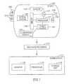
- Figure 1is a schematic illustration of an in-vivo sensing system 100 in accordance with some embodiments of the invention.
- One or more components of system 100may be used in conjunction with, or may be operatively associated with, the devices and/or components described herein or other in-vivo devices in accordance with embodiments of the invention.
- system 100may include a device 140 having a sensor, e.g., an imager 146, one or more illumination sources 142, a power source 145, and a transmitter 141.
- device 140may be implemented using a swallowable capsule, but other sorts of devices or suitable implementations may be used.
- Device 140typically may be or may include an autonomous swallowable capsule, but device 140 may have other shapes and need not be swallowable and/or autonomous. Embodiments of device 140 are typically autonomous, and are typically self-contained. For example, device 140 may be a capsule or other unit where all the components are substantially contained within a container or shell or housing, and where device 140 does not require any wires or cables to, for example, receive power and/or transmit information. In some embodiments, device 140 may be autonomous and non-remote-controllable; in another embodiment, device 140 may be partially or entirely remote-controllable.
- Receiver/recorder 112may receive signals transmitted by the in-vivo device 140, for example, signals carrying image data, sensed data, control data, or the like. Receiver/recorder 112 may, for example, store the received data in a memory unit or a storage unit, or may display the information on a display unit (e.g., in real time or not in real time), for example, using hand-held device or computer.
- a storage unit 119may be, for example, a storage unit 119, a processor 114, and a monitor 118, which may optionally be implemented as a workstation 117, e.g., a computer or a computing platform.
- Workstation 117may be connected to receiver/recorder 112 through a wireless or wired link or connection. Workstation 117 may receive from receiver/recorder 112 data that is received and/or recorded by receiver/recorder 112.
- device 140may include an in-vivo video camera, for example, imager 146, which may capture and transmit images of, for example, the GI tract while device 140 passes through the GI lumen.
- imager 146may capture and transmit images of, for example, the GI tract while device 140 passes through the GI lumen.
- Other lumens and/or body cavitiesmay be imaged and/or sensed by device 140.
- imager 146may include, for example, a Charge Coupled Device (CCD) camera or imager, a Complementary Metal Oxide Semiconductor (CMOS) camera or imager, any other solid state camera or imager, a light detector, a linear imaging sensor, a line imaging sensor, a full frame imaging sensor, a "camera on chip” imaging sensor, a digital camera, a stills camera, a video camera, or other suitable imagers, cameras, or image acquisition components.
- CCDCharge Coupled Device
- CMOSComplementary Metal Oxide Semiconductor
- transmitter 141 of device 140may include a wireless transmitter, e.g., able to operate using radio waves, able to transmit Radio Frequency (RF) signals, or able to transmit other types of communication signals.
- transmitter 141may transmit wireless signals utilizing an antenna 148.
- transmitter 141may transmit data via, for example, wire, cable, optical fiber and/or other suitable methods. Other known wired and/or wireless methods of transmission may be used.
- device 140may optionally include a receiver 196, for example, a wired or wireless (e.g., RF) receiver, able to receive signals from an external transmitter.
- the received signalsmay include, for example, control signals or commands, e.g., to activate and/or otherwise control one or more components of device 140.
- Receiver 196may receive signals, e.g., from outside the patient's body, for example, through antenna 148 or through a different antenna or receiving element.
- signals or datamay be received by a separate receiving unit in device 140.
- transmitter 141 and receiver 196may optionally be implemented using a transceiver unit or an integrated transmitter-receiver unit.
- imager 146 in device 140may be operationally connected to transmitter 141.
- Transmitter 141may transmit images and/or data to, for example, external transceiver or receiver/recorder 112 (e.g., through one or more antennas), which may send the data to processor 114 and/or to storage unit 119.
- Transmitter 141may also include control capability, although control capability may be included in a separate component, e.g., a controller or processor 147.
- Transmitter 141may include any suitable transmitter able to transmit image data, numerical data, other sensed data, and/or other data (e.g., control data) to a receiving device.
- Transmitter 141may also be capable of receiving signals/commands, for example from an external transceiver.
- transmitter 141may include an ultra low power Radio Frequency (RF) high bandwidth transmitter, possibly provided in Chip Scale Package (CSP).
- RFRadio Frequency
- CSPChip Scale Package
- transmitter 141may transmit/receive data via antenna 148.
- Transmitter 141 and/or another unit in device 140e.g., a controller or processor 147, may include control capability, for example, one or more control modules, processing modules, circuitry and/or functionality for controlling device 140, for controlling the operational mode or settings of device 140, and/or for performing control operations or processing operations within device 140.
- Power source 145may include, for example, one or more batteries or power cells.
- power source 145may include silver oxide batteries, lithium batteries, other suitable electrochemical cells having a high energy density, or the like. Other suitable power sources may be used.
- power source 145may receive power or energy from an external power source (e.g., an electromagnetic field generator), which may be external to device 140 and/or external to the body, and may be used to transmit power or energy to in-vivo device 140.
- an external power sourcee.g., an electromagnetic field generator
- power source 145may be internal to device 140, and/or may not require coupling to an external power source, e.g., to receive power.
- Power source 145may provide power to one or more components of device 140, for example, continuously, substantially continuously, or in a non-discrete manner or timing, or in a periodic manner, an intermittent manner, or an otherwise non-continuous manner.
- power source 145may provide power to one or more components of device 140, for example, not necessarily upon-demand, or not necessarily upon a triggering event or an external activation or external excitement.
- transmitter 141may include a processing unit or processor or controller (e.g., controller or processor 147), for example, to process signals and/or data generated by imager 146.
- the processing unitmay be an independent unit or integrated with another component within device 140, e.g., controller or processor 147, or may be implemented as an integral part of imager 146, transmitter 141, or another component, or may not be needed.
- the processing unitmay include, for example, a Central Processing Unit (CPU), a Digital Signal Processor (DSP), a microprocessor, a controller, a chip, a microchip, a controller, circuitry, an Integrated Circuit (IC), an Application-Specific Integrated Circuit (ASIC), or any other suitable multi-purpose or specific processor, controller, circuitry or circuit.
- CPUCentral Processing Unit
- DSPDigital Signal Processor
- ASICApplication-Specific Integrated Circuit
- the processing unit or controllermay be embedded in or integrated with transmitter 141, and may be implemented, for example, using an ASIC.
- imager 146may acquire in-vivo images, for example, continuously, substantially continuously, or in a non-discrete manner, for example, not necessarily upon-demand, or not necessarily upon a triggering event or an external activation or external excitement; or in a periodic manner, an intermittent manner, or an otherwise non-continuous manner.
- transmitter 141may transmit image data continuously, or substantially continuously, for example, not necessarily upon-demand, or not necessarily upon a triggering event or an external activation or external excitement; or in a periodic manner, an intermittent manner, or an otherwise non-continuous manner.
- device 140may include one or more illumination sources 142, for example one or more Light Emitting Diodes (LEDs), "white LEDs", monochromatic LEDs, Organic LEDs (O-LEDs), thin-film LEDs, single-color LED(s), multi-color LED(s), LED(s) emitting viewable light, LED(s) emitting non-viewable light, LED(s) emitting Infra Red (IR) light, an emissive electroluminescent layer or component, Organic Electro-Luminescence (OEL) layer or component, or other suitable light sources.
- LEDsLight Emitting Diodes
- O-LEDsOrganic LEDs
- IRInfra Red
- OELOrganic Electro-Luminescence
- Illumination sources 142may, for example, illuminate a body lumen or cavity being imaged and/or sensed.
- Device 140may optionally include an optical system 150, for example, one or more optical elements, lenses, composite lens assemblies, magnifying lens, optical filters, prisms, gratings, plane mirrors, curved mirrors, concave mirrors or elements, convex mirrors or elements, reflective surfaces, reflective elements, light tunnels, light diverting elements, light focusing elements, or any other suitable optical elements.
- Optical system 150may, for example, aid in focusing reflected light onto imager 146, focusing illuminated light, and/or performing other light processing operations.
- illumination source(s) 142may illuminate continuously, or substantially continuously, for example, not necessarily upon-demand, or not necessarily upon a triggering event or an external activation or external excitement.
- illumination source(s) 142may illuminate a pre-defined number of times per second (e.g., two or four times), substantially continuously, e.g., for a time period of two hours, four hours, eight hours, or the like; or in a periodic manner, an intermittent manner, or an otherwise non-continuous manner.
- the components of device 140may be enclosed within a housing or shell, e.g., capsule-shaped, oblong, oval, spherical, tubular, peanut-shaped, or having other suitable shapes and/or dimensions.
- the housing or shellmay be substantially transparent or semi-transparent, and/or may include one or more portions, windows or domes (e.g., a dome-shaped window, or multiple dome-shaped windows) which may be substantially transparent or semi-transparent.
- one or more illumination source(s) 142 within device 140may illuminate a body lumen through a transparent or semi-transparent portion, window or dome; and light reflected from the body lumen may enter the device 140, for example, through the same transparent or semi-transparent portion, window or dome (e.g., the window on dome on which liposomes or nanocontainers 191 may be located) or, optionally, through another transparent or semi-transparent portion, window or dome, and may be received by optical system 150 and/or imager 146.
- optical system 150 and/or imager 146may receive light, reflected from a body lumen, through the same window or dome through which illumination source(s) 142 illuminate the body lumen.
- Workstation 117may include data processor 114 able to analyze the data received from device 140, and optionally able to separate images related to imaging the body lumen from images or data related to molecular analysis by the liposomes or nanoparticles 191.
- Data processor 114may be in communication with storage unit 119, e.g., able to transfer frame data to and/or from storage unit 119.
- Data processor 114may provide the analyzed data to monitor 118, where a user (e.g., a physician) may view or otherwise use the presented data.
- Data processor 114may analyze the data received via external receiver/recorder 112 or (e.g., directly) from device 140, and may be in communication with storage unit 119, e.g., transferring frame data to and from storage unit 119. Data processor 114 may provide the analyzed data to monitor 118, where a user (e.g., a physician) may view or otherwise use the data.
- data processor 114 and/or workstation 117may be configured for real time processing, and/or may be implemented using a hand-held device. In another embodiment, post processing may be performed, and data or images may be viewed at a later time (e.g., not in real time).
- control capabilitye.g., delay, timing, etc
- a suitable external devicesuch as, for example, data processor 114 or external receiver/recorder 112 having a transmitter or transceiver
- Monitor 118may include, for example, one or more screens, monitors, or suitable display units. Monitor 118, for example, may display one or more images or a stream of images captured and/or transmitted by device 140, e.g., images of the GI tract or of other imaged body lumen or cavity. Additionally or alternatively, monitor 118 may display, for example, control data, location or position data (e.g., data describing or indicating the location or the relative location of device 140), orientation data, and various other suitable data. In some embodiments, for example, both an image and its position (e.g., relative to the body lumen being imaged) or location may be presented using monitor 118 and/or may be stored using storage unit 119. Other systems and methods of storing and/or displaying collected image data and/or other data may be used.
- device 140may transmit image information in discrete portions. Each portion may typically correspond to an image or a frame; other suitable transmission methods may be used. For example, in some embodiments, device 140 may capture and/or acquire an image once every half second, and may transmit the image data to external receiver/recorder 112. Other constant and/or variable capture rates and/or transmission rates may be used.
- the image data recorded and transmittedmay include digital color image data; in alternate embodiments, other image formats (e.g., black and white image data) may be used.
- each frame of image datamay include 256 rows, each row may include 256 pixels, and each pixel may include data for color and brightness according to known methods. According to other embodiments a 320x320 pixel imager may be used.
- Pixel sizemay be, for example, between 5 to 6 microns; other suitable sizes may be used.
- pixelsmay be each fitted with a micro lens.
- a Bayer color filtermay be applied.
- Other suitable data formatsmay be used, and other suitable numbers or types of rows, columns, arrays, pixels, sub-pixels, boxes, super-pixels and/or colors may be used.
- device 140may include one or more sensors 143, instead of or in addition to a sensor such as imager 146.
- Sensor 143may, for example, sense, detect, determine and/or measure one or more values of properties or characteristics of the surrounding of device 140.
- sensor 143may include a pH sensor, a temperature sensor, an electrical conductivity sensor, a pressure sensor, or any other known suitable in-vivo sensor.
- device 140may include a carrier substance 190, e.g., a hydrogel, which may be immobilized or otherwise mounted or coated on an external portion of device 140, e.g., over a dome-shaped optical window of device 140.
- Carrier substance 190may include, for example, conjugated liposomes or nano-containers 191.
- carrier substance 190may be made of or may include crosslinked polymeric chains, in which water or water-based solutions may be dispersed or adsorbed, for example, a hydrogel, e.g., a network of polymer chains that are water-soluble, or a colloidal gel in which water is the dispersion medium, or micelles or polymeric compounds, e.g., cellulose; other absorbent or super-absorbent natural or synthetic polymers may be used. .
- dried formulationsmay be used, e.g. lyophilize liposomes or polymersomes may be embedded in nitrocellulose.
- preservativese.g., Thimerosal, benzyl alcohol, parabens, or the like
- preservativese.g., Thimerosal, benzyl alcohol, parabens, or the like
- carrier substance 190 and liposomes or nano-containers 191may be placed in, or immobilized onto, a band 192, e.g., mounted or coated around or over a portion of device 140, or around or over a portion of a window or a suitable trench in the dome-shaped window of device 140.
- carrier substance 190 and liposomes or nano-containers 191may be placed in, or immobilized onto, an external dome-shaped portion 193, e.g., mounted or coated over a portion of device 140, or around or over a window or dome-shaped window of device 140.
- the carrier substance 190may be coated, for example, for preservation and/or storage while the device 140 is not in-vivo.
- the coatingmay dissolve in-vivo, or only when the device 140 reaches a certain body part (e.g., the colon).
- the coatingmay partially dissolve, for example, to open an inlet gate and/or an outlet gate, thereby creating a flow (e.g., a contuse flow) through the carrier substance 190.
- carrier substance 190 and liposomes or nano-containers 191may be placed externally to the in-vivo device 140, other suitable locations may be used.
- carrier substance 190 and liposomes or nano-containers 191may be placed internally to device 140, e.g., within an internal compartment or chamber or channel, which may be subsequently opened in-vivo (e.g., using a dissolvable gate, a mechanical gate, or the like).
- Other suitable placement, mounting or coating methodsmay be used.
- a reaction chamber within the in-vivo device 140 or connected to the in-vivo device 140may contain immobilized the liposomes or nano-containers 191 for carrying imaging agents that may be specifically reactant to a target analyte.
- Such liposomes or nano-containers 191may include, for example, liposomes, colloidosomes and/or polymerosomes; other suitable nano-containers may be used.
- liposomes or nano-containers 191may include bilayers of phospholipids around a hydrophobic core; in other embodiments, liposomes or nano-containers 191 may be composed of more than bilayers and may include a multilayer of confronting lipid layers.
- conjugated liposomes or nano-containers 191may be filled with, for example, pH sensitive color in low strength buffer possessing a pH different from and/or opposite that of the sample and/or analyte. Rupture of the liposomes or nano-containers 191 may occur as a result of a reaction with a target analyte.
- liposomes or nano-containers 191may include or may be filled with an alternate or additional molecule (e.g., fluorescence material, material having fluorescence properties, or the like) capable of changing optical properties of a substrate.
- an alternate or additional moleculee.g., fluorescence material, material having fluorescence properties, or the like
- Liposome or nano-container 191may be or may include, for example, a microscopic self-assembling spherical vesicle (e.g., liposome, nanosome, or the like) having a membrane composed of, e.g., a phospholipid bilayer.
- Liposome or nano-container 191may include, for example, organic materials, inorganic materials, synthetic materials or polymers, polyphosphate-based materials, or the like.
- Liposome or nano-container 191may be a fluid-filled pouch or compartment, whose walls are made of layers of phospholipids which may be substantially identical to the phospholipids of cell membranes. Liposome or nano-container 191 may have a diameter of approximately 50 nanometers, approximately 100 nanometers, or the like.
- a first shell 181, e.g., an external shell, of the liposome or nano-container 191may be water insoluble; whereas a second shell 182, e.g., an internal shell, of the liposome or nano-container 191 may be water soluble.
- a zone between the first shell 181 and the second shellmay be used as a first nano-compartment 183, e.g., a hydrophobic cavity; whereas a zone inside the second shell 182 may be used as a second nano-compartment 184, e.g., a polar cavity.
- Other numbers or locations of layers, shells, zones and/or nano-compartmentsmay be used.
- reactant or reagent 185may include a specific protein or antibody which may react when in contact with a certain antigen or pathology, e.g., a tumor, a cancerous tumor, an infection, a polyp, or the like.
- reactant or reagent 185may include, for example, pepsin, pepsin 1, pepsin 3, gastrin, gastrin 17, or various other reactants or reagents.
- liposome or nano-container 191may store therein (e.g., within nano-compartment 183 and/or 184) a signaling material 186.
- the signaling material 186may be or may include, for example, a pH-sensitive substance or indicator, a fluorescent substance or indicator, or another substance or indicator which may modify its optical properties (e.g., its color or its light emission or absorption properties) upon modification of the signaling material 186 or upon reaction between the signaling material 186 and another substance (e.g., targeted protein or an analyte present in body fluid).
- signaling material 186may initially (e.g., when stored within liposome or nano-container 191) have a first color, e.g., blue; and may modify its color to a second, different color, e.g., yellow, if signaling material 186 reacts with a body substance or with another material substance present in hydrogel 190.
- first colore.g., blue
- second colore.g., yellow
- signaling material 186may have a first color or a first fluorescence or a first optical property in the presence of a first substance, and a second color or a second fluorescence or a second optical property in the presence of a second substance.
- signaling material 186may have a first color or a first fluorescence or a first optical property in the presence of a first pH level or a first acidity level, and a second color or a second fluorescence or a second optical property in the presence of a second pH level or a second acidity level.
- signaling material 186may have a first color or a first fluorescence or a first optical property in the presence of a water-based substance, and a second color or a second fluorescence or a second optical property in the presence of a lipid-based substance.
- one or more holes, outlets, punctures or openingsmay be created, allowing the signaling material 186 stored within liposome or nano-container 191 to exit and/or to be in contact with the body substance or with the carrier substance 190 (e.g., the hydrogel); thereby resulting in a modification of an optical property of signaling material 186 (e.g., color or fluorescence; for example, modification from blue color to yellow color, or the like).
- the carrier substance 190e.g., the hydrogel
- signaling material 186may include or may be bromothymol blue (indicator) in a solution with low buffer capacity at a pH of approximately 8 or above having a blue color.
- indicatorbromothymol blue
- the acidmay not penetrate the liposome or nano-container 191, there may be no contact between the acid and the signaling material 186 (e.g., the indicator), and thus liposome or nano-container 191 may remain blue.
- stomach acidmay be in contact with the signaling material 186 (e.g., the indicator), and the signaling material 186 (e.g., the indicator) may modify its color (or other optical property), e.g., from blue to yellow.
- the signaling material 186e.g., the indicator
- the signaling material 186may modify its color (or other optical property), e.g., from blue to yellow.
- the modification of optical property of the signaling material 186, or the resulting optical property of signaling material 186may be imaged or otherwise sensed, e.g., by imager 146 of in-vivo device 140.
- imager 146may acquire one or more images, e.g., through a window or a dome-shaped window of device 140.
- the acquired imagemay include, for example, the signaling material 186 having a modified (e.g., non-original) color, and/or a body lumen in which the reaction takes place.
- the liposome or nano-container 191may be initially filled with pH-sensitive substance having a first color (e.g., blue).
- the liposome or nano-container 191may rupture as a result of reaction with a target, e.g., a certain antigen.
- the pH-sensitive substance stored within the liposome or nano-container 191may modify its color into a second color (e.g., yellow).
- the in-vivo imager 146may acquire images of the modified color, and the image data may be transmitted by transmitter 141.
- the in-vivo imager 146 or the sensor 143may acquire the images and/or the change (e.g., increase) in signal of the fluorescent substance, and the sensed data may be transmitted by transmitter 141, e.g., in addition to or instead of the relevant image data.
- in-vivo device 140may be localized, e.g., using one or more localization methods, thereby allowing to determine the location or body part in which the reaction took place, e.g., the location or body part having the antigen, pathology, tumor, cancerous tumor, infection, polyp, or the like.
- Figure 5illustrates an in-vivo device 140 having multiple types of liposomes or nano-containers 191, in accordance with some embodiments of the invention.
- carrier substance 190 and liposomes or nano-containers 191may be placed in, or immobilized onto, a band 192, e.g., mounted or coated around or over a portion of device 140, or around or over a portion of a window or dome-shaped window of device 140.
- Band 192may include multiple portions or areas, for example, a first portion 192A, a second portion 192B, a third portion 192C, or the like; and each portion may include, for example, a different type of liposomes or nano-containers, e.g., a first type of liposomes or nano-containers 191A, a second type of liposomes or nano-containers 191B, a third type of liposomes or nano-containers 191C, respectively.
- the first type of liposomes or nano-containers 191Amay be adapted to react to a first antigen or protein
- the second type of liposomes or nano-containers 191Amay be adapted to react to an enzyme or protein
- the third type of liposomes or nano-containers 191Amay be adapted to react to a tertian hormone or protein, or the like.
- In-vivo device 140 of Figure 5may pass through a body lumen, e.g., the GI tract.
- the first type of liposomes or nano-containers 191Amay be in contact with the first antigen or protein, thereby causing rupture of the liposome or nano-container 191A, and modification of optical property of the content of liposome or nano-container 191A.
- third type of liposomes or nano-containers 191Cmay be in contact with the hormone or third protein, thereby causing rupture of the liposome or nano-container 191C, and modification of optical property of the content of liposome or nano-container 191C.
- the second type of liposomes or nano-containers 191Bmay not be in contact with the enzyme or second protein (e.g., if the enzyme is not present in the patient's body or GI tract), and the content of the second type of liposome or nano-container 191B may not be exposed or may not modify its optical property.
- Device 140may acquire images including the first portion 192A, the second portion 192B, and the third portion 192C.
- the in-vivo imagesmay indicate, for example, that the first and third antigens are detected and may be present in-vivo, whereas the second antigen are not detected and possible may not be present in-vivo.
- reaction by the first type of liposomes or nano-containers 191Amay result in a first modification of optical property (e.g., change of color from blue to yellow), whereas reaction by the by the second type of liposomes or nano-containers 191B may result in a second, different, modification of optical property (e.g., change of color from blue to green, or exposure of fluorescent substance).
- first modification of optical propertye.g., change of color from blue to yellow
- reaction by the by the second type of liposomes or nano-containers 191Bmay result in a second, different, modification of optical property (e.g., change of color from blue to green, or exposure of fluorescent substance).
- reaction by a first type of liposomes or nano-containers 191Amay result in a first modification of optical property (e.g., change of color from blue to yellow); whereas reaction by the by a second type of liposomes or nano-containers 191B may result in a second, different, modification of non-optical properties, e.g., modification in magnetic field or conductivity, which may be detected by sensor 143.
- first modification of optical propertye.g., change of color from blue to yellow
- reaction by the by a second type of liposomes or nano-containers 191Bmay result in a second, different, modification of non-optical properties, e.g., modification in magnetic field or conductivity, which may be detected by sensor 143.
- multiple reactionsmay result in similar, or even substantially identical, modifications of optical property, and may be differentiated or distinguished, for example, based on the location or the relative location of the portions. For example, a change of color from blue to yellow in the first portion 192A, may be distinguished from a change of color from blue to yellow in the third portion 192C, based on the location or the relative location of portions 192A and 192C on the band 192 as imaged by the in-vivo device 140.
- a change of color from a first color to a second color at the location of the first portion 192Amay be used as indication that the first type of liposomes or nano-containers 191A reacted with a first type of antigen; whereas a change of color from the first color to the second color at the location of the first portion 192C, may be used as indication that the third type of liposomes or nano-containers 191C reacted with a third type of antigen.
Landscapes
- Health & Medical Sciences (AREA)
- Life Sciences & Earth Sciences (AREA)
- Surgery (AREA)
- Engineering & Computer Science (AREA)
- General Health & Medical Sciences (AREA)
- Physics & Mathematics (AREA)
- Biomedical Technology (AREA)
- Heart & Thoracic Surgery (AREA)
- Medical Informatics (AREA)
- Molecular Biology (AREA)
- Biophysics (AREA)
- Animal Behavior & Ethology (AREA)
- Pathology (AREA)
- Public Health (AREA)
- Veterinary Medicine (AREA)
- Nuclear Medicine, Radiotherapy & Molecular Imaging (AREA)
- Optics & Photonics (AREA)
- Radiology & Medical Imaging (AREA)
- Measurement Of The Respiration, Hearing Ability, Form, And Blood Characteristics Of Living Organisms (AREA)
- Endoscopes (AREA)
- Investigating Or Analysing Biological Materials (AREA)
Abstract
Description
- The present invention relates in general to in-vivo analysis, and specifically to in-vivo analysis utilizing liposomes and/or nano-containers.
- An atypical concentration or presence of substances in body fluids or in body lumens may be indicative of the biological condition of the body. For example, the presence of elevated concentrations of red blood cells in the gastrointestinal (GI) tract may indicate different pathologies, depending on the location of the bleeding along the GI tract. Likewise, abnormalities in physical conditions of the body, such as, for example, elevated temperature, may indicate pathology. Early detection, identification and location of abnormal conditions may be critical for correctly diagnosing and treating various pathologies. Some diseases, for example, cancer, may be detected by analyzing the blood stream for tumor specific markers, e.g., specific antibodies.
- Devices and systems for in-vivo imaging may be used, for example, to acquire in-vivo images of the GI tract
US 2002/0146368 discloses a swallowable capsule, with a camera system and a transmitter for imaging the digestive tract, having immobilised thereon a reactant (i.e. a polyelectrolyte, a protein or an antibody) which chemically reacts with a substance in a body lumen so as to result in an optically detectable change.- Some embodiments of the invention may allow, for example, in-vivo analysis.
- In some embodiments, for example, an in-vivo imaging device may be coated with liposomes or nano-containers containing a marker, an indicator, a signaling agent or a signaling material. The liposomes or nano-containers may react to a certain antigen in-vivo; following the reaction of the liposomes or nano-containers with the antigen, the signaling material may become visible, may become detectible, and/or may modify its optical property. The in-vivo imaging device may acquire images including the signaling material, thereby indicating the in-vivo presence of the antigen that reacts with the liposomes or nano-containers used.
- In some embodiments, for example, the in-vivo imaging device may be autonomous.
- In some embodiments, for example, the in-vivo imaging device may include a swallowable capsule.
- In some embodiments, for example, a system may include the in-vivo device, which may include a transmitter to transmit the image data to an external receiver and monitor. Embodiments of the invention may provide additional and/or other benefits and/or advantages.
- The subject matter regarded as the invention is particularly pointed out and distinctly claimed in the concluding portion of the specification. The invention, however, both as to organization and method of operation, together with objects, features, and advantages thereof, may best be understood by reference to the following detailed description when read with the accompanying drawings in which:
Figure 1 is a schematic illustration of an in-vivo sensing system in accordance with some embodiments of the invention;Figure 2 is a schematic illustration of an in-vivo imaging device in accordance with an embodiment of the invention;Figure 3 is a schematic illustration of an in-vivo imaging device in accordance with another embodiment of the invention;Figure 4A is a schematic illustration of a liposome or nano-container in accordance with some embodiments of the invention;Figure 4B is an illustration of a liposome or nano-container in accordance with some embodiments of the invention; andFigure 5 is a schematic illustration of an in-vivo imaging device in accordance with yet another embodiment of the invention.- It will be appreciated that for simplicity and clarity of illustration, elements shown in the figures have not necessarily been drawn to scale. For example, the dimensions of some of the elements may be exaggerated relative to other elements for clarity. Further, where considered appropriate, reference numerals may be repeated among the figures to indicate corresponding or analogous elements.
- In the following detailed description, numerous specific details are set forth in order to provide a thorough understanding of the invention. However, it will be understood by those skilled in the art that the present invention may be practiced without these specific details. In other instances, well-known methods, procedures, and components have not been described in detail so as not to obscure the present invention.
- Some embodiments of the present invention are directed to a typically one time use or partially single use detection and/or analysis device. Some embodiments are directed to a typically swallowable in-vivo device that may passively or actively progress through a body lime, e.g., the gastro-intestinal (GI) tract, for example, pushed along by natural peristalsis. Some embodiments are directed to in-vivo sensing devices that may be passed through other body lumens, for example, through blood vessels, the reproductive tract, or the like. The in-vivo device may be, for example, a sensing device, an imaging device, a diagnostic device, a detection device, an analysis device, a therapeutic device, or a combination thereof. In some embodiments, the in-vivo device may include an image sensor or an imager. Other sensors may be included, for example, a pH sensor, a temperature sensor, a pressure sensor, sensors of other in-vivo parameters, sensors of various in-vivo substances or compounds, or the like. Devices, systems and methods according to some embodiments of the present invention, including for example in-vivo sensing devices, receiving systems and/or display systems, may be similar to embodiments described in United States Patent Number
5,604,531 to Iddan et al. , entitled "In-vivo Video Camera System", and/or in United States Patent Application Number09/800,470 2001/0035902 , and/or in United States Patent Application Number10/046,541 2002/0109774 , and/or in United States Patent Application Number10/046,540 2002/0111544 . Devices and systems as described herein may have other configurations and/or sets of components. For example, an external receiver/recorder unit, a processor and a monitor, e.g., in a workstation, such as those described in the above publications, may be suitable for use with some embodiments of the present invention. Devices and systems as described herein may have other configurations and/or other sets of components. For example, the present invention may be practiced using an endoscope, needle, stent, catheter, etc. Some in-vivo devices may be capsule shaped, or may have other shapes, for example, a peanut shape or tubular, spherical, conical, or other suitable shapes. - Some embodiments of the present invention may include, for example, a typically swallowable in-vivo device. In other embodiments, an in-vivo device need not be swallowable and/or autonomous, and may have other shapes or configurations. Some embodiments may be used in various body lumens, for example, the GI tract, blood vessels, the urinary tract, the reproductive tract, or the like. In some embodiments, the in-vivo device may optionally include a sensor, an imager, and/or other suitable components.
- Embodiments of the in-vivo device are typically autonomous and are typically self-contained. For example, the in-vivo device may be or may include a capsule or other unit where all the components are substantially contained within a container, housing or shell, and where the in-vivo device does not require any wires or cables to, for example, receive power or transmit information. The in-vivo device may communicate with an external receiving and display system to provide display of data, control, or other functions. For example, power may be provided by an internal battery or an internal power source, or using a wired or wireless power-receiving system. Other embodiments may have other configurations and capabilities. For example, components may be distributed over multiple sites or units; and control information or other information may be received from an external source.
Figure 1 is a schematic illustration of an in-vivo sensing system 100 in accordance with some embodiments of the invention. One or more components of system 100 may be used in conjunction with, or may be operatively associated with, the devices and/or components described herein or other in-vivo devices in accordance with embodiments of the invention.- In some embodiments, system 100 may include a
device 140 having a sensor, e.g., animager 146, one ormore illumination sources 142, apower source 145, and atransmitter 141. In some embodiments,device 140 may be implemented using a swallowable capsule, but other sorts of devices or suitable implementations may be used. Device 140 typically may be or may include an autonomous swallowable capsule, butdevice 140 may have other shapes and need not be swallowable and/or autonomous. Embodiments ofdevice 140 are typically autonomous, and are typically self-contained. For example,device 140 may be a capsule or other unit where all the components are substantially contained within a container or shell or housing, and wheredevice 140 does not require any wires or cables to, for example, receive power and/or transmit information. In some embodiments,device 140 may be autonomous and non-remote-controllable; in another embodiment,device 140 may be partially or entirely remote-controllable.- Outside a patient's body may be, for example, an external receiver/
recorder 112, which may include, or may associated with, one or more antennas (or antenna elements), optionally arranged as an antenna array. Receiver/recorder 112 may receive signals transmitted by the in-vivo device 140, for example, signals carrying image data, sensed data, control data, or the like. Receiver/recorder 112 may, for example, store the received data in a memory unit or a storage unit, or may display the information on a display unit (e.g., in real time or not in real time), for example, using hand-held device or computer. - Additionally, outside a patient's body may be, for example, a
storage unit 119, aprocessor 114, and amonitor 118, which may optionally be implemented as aworkstation 117, e.g., a computer or a computing platform.Workstation 117 may be connected to receiver/recorder 112 through a wireless or wired link or connection.Workstation 117 may receive from receiver/recorder 112 data that is received and/or recorded by receiver/recorder 112. In some embodiments,workstation 117 may receive the data from receiver/recorder 112 substantially in real-time, and/or while receiver/recorder 112 continues to receive and/or record data from the in-vivo device 140 and while the in-vivo device 140 is operational and/or in-vivo. In some embodiments,device 140 may communicate (e.g., directly or indirectly) with the external receiving and display system (e.g.,workstation 117 or monitor 118) to provide display of data, control, or other functions. - In some embodiments,
device 140 may include an in-vivo video camera, for example,imager 146, which may capture and transmit images of, for example, the GI tract whiledevice 140 passes through the GI lumen. Other lumens and/or body cavities may be imaged and/or sensed bydevice 140. In some embodiments,imager 146 may include, for example, a Charge Coupled Device (CCD) camera or imager, a Complementary Metal Oxide Semiconductor (CMOS) camera or imager, any other solid state camera or imager, a light detector, a linear imaging sensor, a line imaging sensor, a full frame imaging sensor, a "camera on chip" imaging sensor, a digital camera, a stills camera, a video camera, or other suitable imagers, cameras, or image acquisition components. - In some embodiments,
transmitter 141 ofdevice 140 may include a wireless transmitter, e.g., able to operate using radio waves, able to transmit Radio Frequency (RF) signals, or able to transmit other types of communication signals. For example,transmitter 141 may transmit wireless signals utilizing anantenna 148. In other embodiments, such as those wheredevice 140 is or is included within an endoscope,transmitter 141 may transmit data via, for example, wire, cable, optical fiber and/or other suitable methods. Other known wired and/or wireless methods of transmission may be used. - In some embodiments,
device 140 may optionally include areceiver 196, for example, a wired or wireless (e.g., RF) receiver, able to receive signals from an external transmitter. The received signals may include, for example, control signals or commands, e.g., to activate and/or otherwise control one or more components ofdevice 140.Receiver 196 may receive signals, e.g., from outside the patient's body, for example, throughantenna 148 or through a different antenna or receiving element. In some embodiments, signals or data may be received by a separate receiving unit indevice 140. In some embodiments,transmitter 141 andreceiver 196 may optionally be implemented using a transceiver unit or an integrated transmitter-receiver unit. - In some embodiments,
imager 146 indevice 140 may be operationally connected totransmitter 141.Transmitter 141 may transmit images and/or data to, for example, external transceiver or receiver/recorder 112 (e.g., through one or more antennas), which may send the data toprocessor 114 and/or tostorage unit 119.Transmitter 141 may also include control capability, although control capability may be included in a separate component, e.g., a controller orprocessor 147.Transmitter 141 may include any suitable transmitter able to transmit image data, numerical data, other sensed data, and/or other data (e.g., control data) to a receiving device.Transmitter 141 may also be capable of receiving signals/commands, for example from an external transceiver. For example, in some embodiments,transmitter 141 may include an ultra low power Radio Frequency (RF) high bandwidth transmitter, possibly provided in Chip Scale Package (CSP). - In some embodiment,
transmitter 141 may transmit/receive data viaantenna 148.Transmitter 141 and/or another unit indevice 140, e.g., a controller orprocessor 147, may include control capability, for example, one or more control modules, processing modules, circuitry and/or functionality for controllingdevice 140, for controlling the operational mode or settings ofdevice 140, and/or for performing control operations or processing operations withindevice 140. Power source 145 may include, for example, one or more batteries or power cells. For example,power source 145 may include silver oxide batteries, lithium batteries, other suitable electrochemical cells having a high energy density, or the like. Other suitable power sources may be used. For example, in some embodiments (e.g., wheredevice 140 is, or is included in, an endoscope)power source 145 may receive power or energy from an external power source (e.g., an electromagnetic field generator), which may be external todevice 140 and/or external to the body, and may be used to transmit power or energy to in-vivo device 140.- In some embodiments,
power source 145 may be internal todevice 140, and/or may not require coupling to an external power source, e.g., to receive power.Power source 145 may provide power to one or more components ofdevice 140, for example, continuously, substantially continuously, or in a non-discrete manner or timing, or in a periodic manner, an intermittent manner, or an otherwise non-continuous manner. In some embodiments,power source 145 may provide power to one or more components ofdevice 140, for example, not necessarily upon-demand, or not necessarily upon a triggering event or an external activation or external excitement. - Optionally, in some embodiments,
transmitter 141 may include a processing unit or processor or controller (e.g., controller or processor 147), for example, to process signals and/or data generated byimager 146. In some embodiment, the processing unit may be an independent unit or integrated with another component withindevice 140, e.g., controller orprocessor 147, or may be implemented as an integral part ofimager 146,transmitter 141, or another component, or may not be needed. The processing unit may include, for example, a Central Processing Unit (CPU), a Digital Signal Processor (DSP), a microprocessor, a controller, a chip, a microchip, a controller, circuitry, an Integrated Circuit (IC), an Application-Specific Integrated Circuit (ASIC), or any other suitable multi-purpose or specific processor, controller, circuitry or circuit. In some embodiments, for example, the processing unit or controller may be embedded in or integrated withtransmitter 141, and may be implemented, for example, using an ASIC. - In some embodiments,
imager 146 may acquire in-vivo images, for example, continuously, substantially continuously, or in a non-discrete manner, for example, not necessarily upon-demand, or not necessarily upon a triggering event or an external activation or external excitement; or in a periodic manner, an intermittent manner, or an otherwise non-continuous manner. - In some embodiments,
transmitter 141 may transmit image data continuously, or substantially continuously, for example, not necessarily upon-demand, or not necessarily upon a triggering event or an external activation or external excitement; or in a periodic manner, an intermittent manner, or an otherwise non-continuous manner. - In some embodiments,
device 140 may include one ormore illumination sources 142, for example one or more Light Emitting Diodes (LEDs), "white LEDs", monochromatic LEDs, Organic LEDs (O-LEDs), thin-film LEDs, single-color LED(s), multi-color LED(s), LED(s) emitting viewable light, LED(s) emitting non-viewable light, LED(s) emitting Infra Red (IR) light, an emissive electroluminescent layer or component, Organic Electro-Luminescence (OEL) layer or component, or other suitable light sources. Illumination sources 142 may, for example, illuminate a body lumen or cavity being imaged and/or sensed.Device 140 may optionally include anoptical system 150, for example, one or more optical elements, lenses, composite lens assemblies, magnifying lens, optical filters, prisms, gratings, plane mirrors, curved mirrors, concave mirrors or elements, convex mirrors or elements, reflective surfaces, reflective elements, light tunnels, light diverting elements, light focusing elements, or any other suitable optical elements.Optical system 150 may, for example, aid in focusing reflected light ontoimager 146, focusing illuminated light, and/or performing other light processing operations.- In some embodiments, illumination source(s) 142 may illuminate continuously, or substantially continuously, for example, not necessarily upon-demand, or not necessarily upon a triggering event or an external activation or external excitement. In some embodiments, for example, illumination source(s) 142 may illuminate a pre-defined number of times per second (e.g., two or four times), substantially continuously, e.g., for a time period of two hours, four hours, eight hours, or the like; or in a periodic manner, an intermittent manner, or an otherwise non-continuous manner.
- In some embodiments, the components of
device 140 may be enclosed within a housing or shell, e.g., capsule-shaped, oblong, oval, spherical, tubular, peanut-shaped, or having other suitable shapes and/or dimensions. The housing or shell may be substantially transparent or semi-transparent, and/or may include one or more portions, windows or domes (e.g., a dome-shaped window, or multiple dome-shaped windows) which may be substantially transparent or semi-transparent. For example, one or more illumination source(s) 142 withindevice 140 may illuminate a body lumen through a transparent or semi-transparent portion, window or dome; and light reflected from the body lumen may enter thedevice 140, for example, through the same transparent or semi-transparent portion, window or dome (e.g., the window on dome on which liposomes ornanocontainers 191 may be located) or, optionally, through another transparent or semi-transparent portion, window or dome, and may be received byoptical system 150 and/orimager 146. In some embodiments, for example,optical system 150 and/orimager 146 may receive light, reflected from a body lumen, through the same window or dome through which illumination source(s) 142 illuminate the body lumen.Workstation 117 may includedata processor 114 able to analyze the data received fromdevice 140, and optionally able to separate images related to imaging the body lumen from images or data related to molecular analysis by the liposomes ornanoparticles 191.Data processor 114 may be in communication withstorage unit 119, e.g., able to transfer frame data to and/or fromstorage unit 119.Data processor 114 may provide the analyzed data to monitor 118, where a user (e.g., a physician) may view or otherwise use the presented data.Data processor 114 may analyze the data received via external receiver/recorder 112 or (e.g., directly) fromdevice 140, and may be in communication withstorage unit 119, e.g., transferring frame data to and fromstorage unit 119.Data processor 114 may provide the analyzed data to monitor 118, where a user (e.g., a physician) may view or otherwise use the data. In some embodiments,data processor 114 and/orworkstation 117 may be configured for real time processing, and/or may be implemented using a hand-held device. In another embodiment, post processing may be performed, and data or images may be viewed at a later time (e.g., not in real time). In the case that control capability (e.g., delay, timing, etc) is external todevice 140, a suitable external device (such as, for example,data processor 114 or external receiver/recorder 112 having a transmitter or transceiver) may transmit one or more control signals todevice 140. Monitor 118 may include, for example, one or more screens, monitors, or suitable display units.Monitor 118, for example, may display one or more images or a stream of images captured and/or transmitted bydevice 140, e.g., images of the GI tract or of other imaged body lumen or cavity. Additionally or alternatively, monitor 118 may display, for example, control data, location or position data (e.g., data describing or indicating the location or the relative location of device 140), orientation data, and various other suitable data. In some embodiments, for example, both an image and its position (e.g., relative to the body lumen being imaged) or location may be presented usingmonitor 118 and/or may be stored usingstorage unit 119. Other systems and methods of storing and/or displaying collected image data and/or other data may be used.- Typically,
device 140 may transmit image information in discrete portions. Each portion may typically correspond to an image or a frame; other suitable transmission methods may be used. For example, in some embodiments,device 140 may capture and/or acquire an image once every half second, and may transmit the image data to external receiver/recorder 112. Other constant and/or variable capture rates and/or transmission rates may be used. Typically, the image data recorded and transmitted may include digital color image data; in alternate embodiments, other image formats (e.g., black and white image data) may be used. In some embodiments, each frame of image data may include 256 rows, each row may include 256 pixels, and each pixel may include data for color and brightness according to known methods. According to other embodiments a 320x320 pixel imager may be used. Pixel size may be, for example, between 5 to 6 microns; other suitable sizes may be used. According to some embodiments, pixels may be each fitted with a micro lens. For example, a Bayer color filter may be applied. Other suitable data formats may be used, and other suitable numbers or types of rows, columns, arrays, pixels, sub-pixels, boxes, super-pixels and/or colors may be used. - Optionally,
device 140 may include one ormore sensors 143, instead of or in addition to a sensor such asimager 146.Sensor 143 may, for example, sense, detect, determine and/or measure one or more values of properties or characteristics of the surrounding ofdevice 140. For example,sensor 143 may include a pH sensor, a temperature sensor, an electrical conductivity sensor, a pressure sensor, or any other known suitable in-vivo sensor. - In some embodiments,
device 140 may include acarrier substance 190, e.g., a hydrogel, which may be immobilized or otherwise mounted or coated on an external portion ofdevice 140, e.g., over a dome-shaped optical window ofdevice 140.Carrier substance 190 may include, for example, conjugated liposomes or nano-containers 191. - In some embodiments,
carrier substance 190 may be made of or may include crosslinked polymeric chains, in which water or water-based solutions may be dispersed or adsorbed, for example, a hydrogel, e.g., a network of polymer chains that are water-soluble, or a colloidal gel in which water is the dispersion medium, or micelles or polymeric compounds, e.g., cellulose; other absorbent or super-absorbent natural or synthetic polymers may be used. .In another embodiment, dried formulations may be used, e.g. lyophilize liposomes or polymersomes may be embedded in nitrocellulose. In other embodiments, preservatives (e.g., Thimerosal, benzyl alcohol, parabens, or the like) may be used or added. - In some embodiments, for example, as illustrated in
Figure 2 ,carrier substance 190 and liposomes or nano-containers 191 may be placed in, or immobilized onto, aband 192, e.g., mounted or coated around or over a portion ofdevice 140, or around or over a portion of a window or a suitable trench in the dome-shaped window ofdevice 140. - In some embodiments, for example, as illustrated in
Figure 3 ,carrier substance 190 and liposomes or nano-containers 191 may be placed in, or immobilized onto, an external dome-shapedportion 193, e.g., mounted or coated over a portion ofdevice 140, or around or over a window or dome-shaped window ofdevice 140. - In some embodiments, the carrier substance 190 (e.g., hydrogel) may be coated, for example, for preservation and/or storage while the
device 140 is not in-vivo. For example, the coating may dissolve in-vivo, or only when thedevice 140 reaches a certain body part (e.g., the colon). In some embodiments, the coating may partially dissolve, for example, to open an inlet gate and/or an outlet gate, thereby creating a flow (e.g., a contuse flow) through thecarrier substance 190. - Although
Figure 2 and Figure 3 demonstrate the placement ofcarrier substance 190 and liposomes or nano-containers 191 externally to the in-vivo device 140, other suitable locations may be used. In some embodiments, for example,carrier substance 190 and liposomes or nano-containers 191 may be placed internally todevice 140, e.g., within an internal compartment or chamber or channel, which may be subsequently opened in-vivo (e.g., using a dissolvable gate, a mechanical gate, or the like). Other suitable placement, mounting or coating methods may be used. - For example, in some embodiments, a reaction chamber within the in-
vivo device 140 or connected to the in-vivo device 140 may contain immobilized the liposomes or nano-containers 191 for carrying imaging agents that may be specifically reactant to a target analyte. Such liposomes or nano-containers 191may include, for example, liposomes, colloidosomes and/or polymerosomes; other suitable nano-containers may be used. In some embodiments, for example, liposomes or nano-containers 191may include bilayers of phospholipids around a hydrophobic core; in other embodiments, liposomes or nano-containers 191 may be composed of more than bilayers and may include a multilayer of confronting lipid layers. - In some embodiments, conjugated liposomes or nano-containers 191 (e.g., lyophilezed conjugated liposomes, or a liposome having a conjugated antibody integrated therein) may be filled with, for example, pH sensitive color in low strength buffer possessing a pH different from and/or opposite that of the sample and/or analyte. Rupture of the liposomes or nano-
containers 191 may occur as a result of a reaction with a target analyte. Upon rupturing of the liposomes or nano-containers 191 and exposure of, for example, the pH sensitive color to the sample, a change of color may occur that may be, for example, optically detectible and/or visible and/or may be imaged. In other embodiments, liposomes or nano-containers 191, e.g., polymersome, may include or may be filled with an alternate or additional molecule (e.g., fluorescence material, material having fluorescence properties, or the like) capable of changing optical properties of a substrate. - Reference is made to
Figure 4A , which illustrates a liposome or nano-container 191 in accordance with some embodiments of the invention, and toFigure 4B , which illustrates a liposome or nano-container 191 in accordance with some embodiments of the invention: Liposome or nano-container 191 may be or may include, for example, a microscopic self-assembling spherical vesicle (e.g., liposome, nanosome, or the like) having a membrane composed of, e.g., a phospholipid bilayer. Liposome or nano-container 191 may include, for example, organic materials, inorganic materials, synthetic materials or polymers, polyphosphate-based materials, or the like. Liposome or nano-container 191 may be a fluid-filled pouch or compartment, whose walls are made of layers of phospholipids which may be substantially identical to the phospholipids of cell membranes. Liposome or nano-container 191 may have a diameter of approximately 50 nanometers, approximately 100 nanometers, or the like. - In some embodiments, for example, a
first shell 181, e.g., an external shell, of the liposome or nano-container 191 may be water insoluble; whereas asecond shell 182, e.g., an internal shell, of the liposome or nano-container 191 may be water soluble. In some embodiments, for example, a zone between thefirst shell 181 and the second shell may be used as a first nano-compartment 183, e.g., a hydrophobic cavity; whereas a zone inside thesecond shell 182 may be used as a second nano-compartment 184, e.g., a polar cavity. Other numbers or locations of layers, shells, zones and/or nano-compartments may be used. - In some embodiments, an external layer (or a portion of an external layer) of the liposome or nano-
container 191 may include, or may be connected to, a reactant orreagent 185. For example, the reactant orreagent 185 may be or may include a protein, a hormone, an enzyme, an antibody, a targeting agent, an active part of an antibody, a "hotspot" of an antibody or a protein (e.g., minimal functional domains involved in protein-to-protein interactions and sufficient to induce a biological or chemical response), a modified antibody, a modified antigen, or the like. For example, reactant orreagent 185 may include a specific protein or antibody which may react when in contact with a certain antigen or pathology, e.g., a tumor, a cancerous tumor, an infection, a polyp, or the like. In some embodiments, for example, reactant orreagent 185 may include, for example, pepsin, pepsin 1, pepsin 3, gastrin, gastrin 17, or various other reactants or reagents. - In some embodiments, liposome or nano-
container 191 may store therein (e.g., within nano-compartment 183 and/or 184) asignaling material 186. The signalingmaterial 186 may be or may include, for example, a pH-sensitive substance or indicator, a fluorescent substance or indicator, or another substance or indicator which may modify its optical properties (e.g., its color or its light emission or absorption properties) upon modification of thesignaling material 186 or upon reaction between the signalingmaterial 186 and another substance (e.g., targeted protein or an analyte present in body fluid). For example, in some embodiments, signalingmaterial 186 may initially (e.g., when stored within liposome or nano-container 191) have a first color, e.g., blue; and may modify its color to a second, different color, e.g., yellow, if signalingmaterial 186 reacts with a body substance or with another material substance present inhydrogel 190. - In some embodiments, for example, signaling
material 186 may have a first color or a first fluorescence or a first optical property in the presence of a first substance, and a second color or a second fluorescence or a second optical property in the presence of a second substance. In some embodiments, for example, signalingmaterial 186 may have a first color or a first fluorescence or a first optical property in the presence of a first pH level or a first acidity level, and a second color or a second fluorescence or a second optical property in the presence of a second pH level or a second acidity level. In some embodiments, for example, signalingmaterial 186 may have a first color or a first fluorescence or a first optical property in the presence of a water-based substance, and a second color or a second fluorescence or a second optical property in the presence of a lipid-based substance. - Referring again to
Figure 1 , thedevice 140 may be inserted in-vivo, for example, by swallowing a swallowable capsule, and may pass through a body lumen. The liposome or nano-container 191 may be in contact with a body substance which may react with reactant orreagent 185, e.g., a certain antigen or pathology, a tumor, a cancerous tumor, an infection, a polyp, or the like. The reaction may cause breaking, opening, rupture, collapsing, dissolution, fusion, or puncturing of liposome or nano-container 191, or of one or more layers (e.g., an external layer, or a portion thereof) of liposome or nano-container 191. For example, one or more holes, outlets, punctures or openings may be created, allowing thesignaling material 186 stored within liposome or nano-container 191 to exit and/or to be in contact with the body substance or with the carrier substance 190 (e.g., the hydrogel); thereby resulting in a modification of an optical property of signaling material 186 (e.g., color or fluorescence; for example, modification from blue color to yellow color, or the like). - In some embodiments, for example, signaling
material 186 may include or may be bromothymol blue (indicator) in a solution with low buffer capacity at a pH of approximately 8 or above having a blue color. When liposome or nano-container 191 is in contact .with healthy stomach acid, the acid may not penetrate the liposome or nano-container 191, there may be no contact between the acid and the signaling material 186 (e.g., the indicator), and thus liposome or nano-container 191 may remain blue. In contrast, if the stomach acid contains targeted proteins, e.g., above a threshold value, liposome or nano-container 191 may deteriorate, the stomach acid may be in contact with the signaling material 186 (e.g., the indicator), and the signaling material 186 (e.g., the indicator) may modify its color (or other optical property), e.g., from blue to yellow. - In some embodiments, the modification of optical property of the
signaling material 186, or the resulting optical property of signalingmaterial 186, may be imaged or otherwise sensed, e.g., byimager 146 of in-vivo device 140. For example,imager 146 may acquire one or more images, e.g., through a window or a dome-shaped window ofdevice 140. The acquired image may include, for example, the signalingmaterial 186 having a modified (e.g., non-original) color, and/or a body lumen in which the reaction takes place. The detection of the modification of the optical property of signalingmaterial 186, and/or the detection of signalingmaterial 186 which may now be external to the liposome or nano-container 191, may indicate that a reactance took place between reagent orreactant 185 and its corresponding antigen, and may indicate the presence of the corresponding antigen, e.g., a pathology, a tumor, a cancerous tumor, an infection, a polyp, or the like. - In some embodiments, for example, the liposome or nano-
container 191 may be initially filled with pH-sensitive substance having a first color (e.g., blue). The liposome or nano-container 191 may rupture as a result of reaction with a target, e.g., a certain antigen. The pH-sensitive substance stored within the liposome or nano-container 191 may modify its color into a second color (e.g., yellow). The in-vivo imager 146 may acquire images of the modified color, and the image data may be transmitted bytransmitter 141. - In some embodiments,
device 140 may transmit digital color image information which may include color information of the liposome or nano-container 191, e.g., in discrete portions; for example, a discrete portion may correspond to an image or a frame; other suitable transmission methods may be used. In some embodiments,device 140 may capture and/or acquire an image, for example, once every half second; other capture rates, constant or variable, may be used. In some embodiments,device 140 may be used for locating the disorder or pathology, and/or for determining its nature, e.g., distinguishing between a benign and malignant polyps or tumors. - In other embodiments, for example, the liposome or nano-
container 191 may be initially filled with fluorescent substance. The liposome or nano-container 191 may rupture as a result of reaction with a target, e.g., a certain antigen. The fluorescent substance stored within the liposome or nano-container 191 may be exposed or may exit the liposome or nano-container 191 and as a result change (e.g., increase) its excitation properties. The in-vivo imager 146 or the sensor 143 (e.g., a light sensor) may acquire the images and/or the change (e.g., increase) in signal of the fluorescent substance, and the sensed data may be transmitted bytransmitter 141, e.g., in addition to or instead of the relevant image data. - In some embodiments, in-
vivo device 140 may be localized, e.g., using one or more localization methods, thereby allowing to determine the location or body part in which the reaction took place, e.g., the location or body part having the antigen, pathology, tumor, cancerous tumor, infection, polyp, or the like. Figure 5 illustrates an in-vivo device 140 having multiple types of liposomes or nano-containers 191, in accordance with some embodiments of the invention. For example,carrier substance 190 and liposomes or nano-containers 191 may be placed in, or immobilized onto, aband 192, e.g., mounted or coated around or over a portion ofdevice 140, or around or over a portion of a window or dome-shaped window ofdevice 140. Band 192 may include multiple portions or areas, for example, afirst portion 192A, asecond portion 192B, athird portion 192C, or the like; and each portion may include, for example, a different type of liposomes or nano-containers, e.g., a first type of liposomes or nano-containers 191A, a second type of liposomes or nano-containers 191B, a third type of liposomes or nano-containers 191C, respectively. For example, the first type of liposomes or nano-containers 191A may be adapted to react to a first antigen or protein, the second type of liposomes or nano-containers 191A may be adapted to react to an enzyme or protein, the third type of liposomes or nano-containers 191A may be adapted to react to a tertian hormone or protein, or the like.- In-
vivo device 140 ofFigure 5 may pass through a body lumen, e.g., the GI tract. The first type of liposomes or nano-containers 191A may be in contact with the first antigen or protein, thereby causing rupture of the liposome or nano-container 191A, and modification of optical property of the content of liposome or nano-container 191A. Similarly, third type of liposomes or nano-containers 191C may be in contact with the hormone or third protein, thereby causing rupture of the liposome or nano-container 191C, and modification of optical property of the content of liposome or nano-container 191C. In contrast, the second type of liposomes or nano-containers 191B may not be in contact with the enzyme or second protein (e.g., if the enzyme is not present in the patient's body or GI tract), and the content of the second type of liposome or nano-container 191B may not be exposed or may not modify its optical property.Device 140 may acquire images including thefirst portion 192A, thesecond portion 192B, and thethird portion 192C. The in-vivo images may indicate, for example, that the first and third antigens are detected and may be present in-vivo, whereas the second antigen are not detected and possible may not be present in-vivo. - In some embodiments, reaction by the first type of liposomes or nano-
containers 191A may result in a first modification of optical property (e.g., change of color from blue to yellow), whereas reaction by the by the second type of liposomes or nano-containers 191B may result in a second, different, modification of optical property (e.g., change of color from blue to green, or exposure of fluorescent substance). - In some embodiments, reaction by a first type of liposomes or nano-
containers 191A may result in a first modification of optical property (e.g., change of color from blue to yellow); whereas reaction by the by a second type of liposomes or nano-containers 191B may result in a second, different, modification of non-optical properties, e.g., modification in magnetic field or conductivity, which may be detected bysensor 143. - In other embodiments, multiple reactions may result in similar, or even substantially identical, modifications of optical property, and may be differentiated or distinguished, for example, based on the location or the relative location of the portions. For example, a change of color from blue to yellow in the
first portion 192A, may be distinguished from a change of color from blue to yellow in thethird portion 192C, based on the location or the relative location ofportions band 192 as imaged by the in-vivo device 140. For example, a change of color from a first color to a second color at the location of thefirst portion 192A, may be used as indication that the first type of liposomes or nano-containers 191A reacted with a first type of antigen; whereas a change of color from the first color to the second color at the location of thefirst portion 192C, may be used as indication that the third type of liposomes or nano-containers 191C reacted with a third type of antigen.
Claims (9)
- An in vivo imaging device (140) comprising:- a housing, said housing comprising a window around or over a portion of which a substance is coated;- an illumination source (142) located within the housing to illuminate a body lumen through the window;- an imager (146) to receive light reflected from the body lumen through both coated and uncoated portions of the window; and- a transmitter (141) to transmit image data to a receiving system (112);
characterised in that,
said substance comprises liposomes (191, 191A, 191B, 191C) containing a marker (186), which marker (186) becomes visible and/or modifies an optical property following a reaction of said liposomes (191, 191A, 191B, 191C) with a target analyte, whereby the imager acquires images which include a marking, created by the marker (186), subsequent to the liposomes (191, 191A, 191B, 191C) reacting with the target analyte. - The imaging device (140) according to claim 1, wherein the housing is capsule-shaped.
- The imaging device (140) according to claim 1, further comprising an optical system (150) to focus light reflected from the body lumen onto said imager (146) .
- The imaging device (140) according to claim 1, wherein a carrier substance (190) is also coated around or over the portion of the window.
- The imaging device (140) according to claim 4, wherein said carrier substance (190) is made of a material selected from a group consisting of: crosslinked polymeric chains in which water is dispersed, colloidal gel in which water is the dispersion medium, micelles or polymeric compounds, or absorbent natural or synthetic polymers.
- The imaging device (140) according to claim 4, wherein said carrier substance (190) is a hydrogel.
- The imaging device (140) according to claim 1, wherein the portion of the window includes multiple areas (192A, 192B, 192C), and wherein each area (192A, 192B, 192C) is coated with a different type of liposomes (191A, 191B, 191C).
- The imaging device (140) according to claim 1, wherein said marker (186) is a fluorescent substance.
- The imaging device (140) according to claim 1, wherein said marker (186) comprises a pH sensitive color in a low strength buffer possessing a pH different from the pH of the target analyte, whereby a change of color occurs when the pH sensitive color is exposed to the target analyte.
Applications Claiming Priority (2)
| Application Number | Priority Date | Filing Date | Title |
|---|---|---|---|
| US78811406P | 2006-04-03 | 2006-04-03 | |
| PCT/IL2007/000458WO2007113839A2 (en) | 2006-04-03 | 2007-04-10 | Device, system and method for in-vivo analysis |
Publications (3)
| Publication Number | Publication Date |
|---|---|
| EP2007433A2 EP2007433A2 (en) | 2008-12-31 |
| EP2007433A4 EP2007433A4 (en) | 2010-03-31 |
| EP2007433B1true EP2007433B1 (en) | 2011-10-26 |
Family
ID=38564082
Family Applications (1)
| Application Number | Title | Priority Date | Filing Date |
|---|---|---|---|
| EP07736198ANot-in-forceEP2007433B1 (en) | 2006-04-03 | 2007-04-10 | Device, system and method for in-vivo analysis |
Country Status (5)
| Country | Link |
|---|---|
| US (1) | US8663093B2 (en) |
| EP (1) | EP2007433B1 (en) |
| JP (1) | JP2009532168A (en) |
| AT (1) | ATE531199T1 (en) |
| WO (1) | WO2007113839A2 (en) |
Families Citing this family (12)
| Publication number | Priority date | Publication date | Assignee | Title |
|---|---|---|---|---|
| US8738106B2 (en)* | 2005-01-31 | 2014-05-27 | Given Imaging, Ltd | Device, system and method for in vivo analysis |
| US20100322866A1 (en)* | 2006-04-03 | 2010-12-23 | Elisha Rabinovitz | Device, system and method for in-vivo analysis |
| JP2009532168A (en) | 2006-04-03 | 2009-09-10 | ギブン イメージング リミテッド | Apparatus, system and method for in vivo analysis |
| US8187174B2 (en)* | 2007-01-22 | 2012-05-29 | Capso Vision, Inc. | Detection of when a capsule camera enters into or goes out of a human body and associated operations |
| US20110184293A1 (en)* | 2008-07-10 | 2011-07-28 | Elisha Rabinovitz | Device, method and kit for in vivo detection of a biomarker |
| JP5006474B2 (en)* | 2009-08-28 | 2012-08-22 | オリンパスメディカルシステムズ株式会社 | Receiving system |
| JP5642373B2 (en)* | 2009-10-23 | 2014-12-17 | オリンパス株式会社 | Portable wireless terminal, wireless communication system, and wireless communication method for portable wireless terminal |
| EP2571573A4 (en)* | 2010-03-17 | 2013-12-04 | Photopill Medical Ltd | Capsule phototherapy |
| US8771201B2 (en)* | 2010-06-02 | 2014-07-08 | Vital Herd, Inc. | Health monitoring bolus |
| CN103687646B (en) | 2011-03-17 | 2016-09-21 | 基文影像公司 | Capsule phototherapy |
| US10433708B1 (en) | 2017-06-30 | 2019-10-08 | Bruce Yacyshyn | Industrial operation having a monitoring system and method |
| JP2021159156A (en)* | 2020-03-30 | 2021-10-11 | 英敏 太田 | Capsule-type sensor |
Family Cites Families (116)
| Publication number | Priority date | Publication date | Assignee | Title |
|---|---|---|---|---|
| US3971362A (en)* | 1972-10-27 | 1976-07-27 | The United States Of America As Represented By The Administrator Of The National Aeronautics And Space Administration | Miniature ingestible telemeter devices to measure deep-body temperature |
| CS175782B1 (en)* | 1974-10-16 | 1977-05-31 | ||
| JPS5294681A (en) | 1976-02-05 | 1977-08-09 | Seiko Instr & Electronics | Medical capsule |
| US4038485A (en)* | 1976-03-18 | 1977-07-26 | Miles Laboratories, Inc. | Test composition, device, and method |
| US4239040A (en)* | 1976-10-19 | 1980-12-16 | Kabushiki Kaisha Daini Seikosha | Capsule for medical use |
| JPS5519124A (en)* | 1978-07-27 | 1980-02-09 | Olympus Optical Co | Camera system for medical treatment |
| JPS5697872A (en)* | 1980-01-07 | 1981-08-06 | Fuji Photo Film Co Ltd | Measuring material for concentration of hemoglobin in blood |
| US5993378A (en)* | 1980-10-28 | 1999-11-30 | Lemelson; Jerome H. | Electro-optical instruments and methods for treating disease |
| US4803992A (en)* | 1980-10-28 | 1989-02-14 | Lemelson Jerome H | Electro-optical instruments and methods for producing same |
| JPS57156736A (en)* | 1981-03-23 | 1982-09-28 | Olympus Optical Co | Therapeutic capsule apparatus |
| JPS57163309A (en) | 1981-04-01 | 1982-10-07 | Olympus Optical Co Ltd | Capsule apparatus for medical use |
| US4605630A (en)* | 1983-07-27 | 1986-08-12 | Cooper Lipotech Inc. | Large-liposome agglutination reagent and method |
| US4708933A (en) | 1984-06-12 | 1987-11-24 | Leaf Huang | Immunoliposome assay-methods and products |
| DE3440177A1 (en) | 1984-11-02 | 1986-05-15 | Friedrich Dipl.-Ing. 8031 Eichenau Hilliges | Television recording and replay device for endoscopy on human and animal bodies |
| US4689621A (en)* | 1986-03-31 | 1987-08-25 | The United States Of America As Represented By The Administrator Of The National Aeronautics And Space Administration | Temperature responsive transmitter |
| JPH0649038B2 (en) | 1986-04-14 | 1994-06-29 | 財団法人ライフテクノロジー研究所 | Medical capsule |
| US5252494A (en)* | 1986-06-25 | 1993-10-12 | Trustees Of Tufts College | Fiber optic sensors, apparatus, and detection methods using controlled release polymers and reagent formulations held within a polymeric reaction matrix |
| US5114864A (en)* | 1986-06-25 | 1992-05-19 | Trustees Of Tufts College | Fiber optic sensors, apparatus, and detection methods using fluid erodible controlled release polymers for delivery of reagent formulations |
| JPH0684970B2 (en)* | 1987-03-31 | 1994-10-26 | 株式会社京都医科学研究所 | Method of detecting occult blood in feces |
| US5173406A (en)* | 1987-05-06 | 1992-12-22 | Teijin Limited | Liposome immunoassay method and kit therefor |
| JPH07107536B2 (en) | 1987-06-11 | 1995-11-15 | 鐘淵化学工業株式会社 | Highly sensitive immunoassay using liposome |
| US5081040A (en)* | 1987-06-29 | 1992-01-14 | Helena Laboratories Corporation | Composition and kit for testing for occult blood in human and animal excretions, fluids, or tissue matrixes |
| US4844076A (en)* | 1988-08-26 | 1989-07-04 | The Johns Hopkins University | Ingestible size continuously transmitting temperature monitoring pill |
| DE3836349A1 (en)* | 1988-10-25 | 1990-05-03 | Forschungsgesellschaft Fuer Bi | CATHETER FOR MEASURING MOTILITY AND PERISTALTICS IN HOSE-SHAPED ORGANS WHICH CONTAIN THEIR CONTENT BY SIMULTANEOUS MULTIPLE IMPEDANCE MEASUREMENT |
| US4885077A (en)* | 1988-11-17 | 1989-12-05 | Becton, Dickinson And Company | Composite membrane, method for its preparation and electrolyte sensor including same |
| US5306623A (en)* | 1989-08-28 | 1994-04-26 | Lifescan, Inc. | Visual blood glucose concentration test strip |
| EP0419729A1 (en)* | 1989-09-29 | 1991-04-03 | Siemens Aktiengesellschaft | Position finding of a catheter by means of non-ionising fields |
| GB9018660D0 (en)* | 1990-08-24 | 1990-10-10 | Imperial College | Probe system |
| JPH04109927A (en) | 1990-08-31 | 1992-04-10 | Toshiba Corp | Electronic endoscope apparatus |
| JPH04138128A (en) | 1990-09-28 | 1992-05-12 | Shimadzu Corp | Gastric fluid sampling device |
| CA2060067A1 (en)* | 1991-01-28 | 1992-07-29 | Lilip Lau | Stent delivery system |
| JP2768029B2 (en) | 1991-02-19 | 1998-06-25 | 日新電機株式会社 | Digestive system diagnostic device |
| JPH05200015A (en) | 1991-03-14 | 1993-08-10 | Olympus Optical Co Ltd | Medical capsule device |
| US5395366A (en)* | 1991-05-30 | 1995-03-07 | The State University Of New York | Sampling capsule and process |
| US5279607A (en)* | 1991-05-30 | 1994-01-18 | The State University Of New York | Telemetry capsule and process |
| US5330427A (en)* | 1991-07-02 | 1994-07-19 | Ortho Pharmaceutical Corporation | Prefilled suppository applicator |
| US5211165A (en)* | 1991-09-03 | 1993-05-18 | General Electric Company | Tracking system to follow the position and orientation of a device with radiofrequency field gradients |
| FR2688997A1 (en) | 1992-03-26 | 1993-10-01 | Lambert Alain | Autonomous telemetric capsule for exploring small bowel - contains sampler for carrying out mucous biopsies, radio transmitter and position detector |
| JPH05281233A (en) | 1992-04-06 | 1993-10-29 | Kanegafuchi Chem Ind Co Ltd | Reagent for immunoassay |
| AU675077B2 (en)* | 1992-08-14 | 1997-01-23 | British Telecommunications Public Limited Company | Position location system |
| IL102930A (en)* | 1992-08-25 | 1997-03-18 | Yissum Res Dev Co | Electrobiochemical analytical method and electrodes |
| US6180135B1 (en)* | 1994-08-11 | 2001-01-30 | The Regents Of The University Of California | Three-dimensional colorimetric assay assemblies |
| US5362478A (en)* | 1993-03-26 | 1994-11-08 | Vivorx Pharmaceuticals, Inc. | Magnetic resonance imaging with fluorocarbons encapsulated in a cross-linked polymeric shell |
| US5460969A (en)* | 1993-03-15 | 1995-10-24 | Fielder; Paul N. | Method for differentiating the source of occult gastrointestinal bleeding |
| JP3321235B2 (en) | 1993-04-07 | 2002-09-03 | オリンパス光学工業株式会社 | Medical capsule and medical capsule detection device |
| US5385846A (en)* | 1993-06-03 | 1995-01-31 | Boehringer Mannheim Corporation | Biosensor and method for hematocrit determination |
| US5447868A (en)* | 1993-09-14 | 1995-09-05 | Propper Manufacturing Co. Inc. | Method, reagent and kit for the detection of fecal occult blood |
| US5833602A (en)* | 1993-09-20 | 1998-11-10 | Osemwota; Omoigui | Process of continuous noninvasive hemometry |
| JP3279409B2 (en) | 1993-10-18 | 2002-04-30 | オリンパス光学工業株式会社 | Medical capsule device |
| US5479935A (en)* | 1993-10-21 | 1996-01-02 | Synectics Medical, Inc. | Ambulatory reflux monitoring system |
| ZA948393B (en)* | 1993-11-01 | 1995-06-26 | Polartechnics Ltd | Method and apparatus for tissue type recognition |
| IL108352A (en)* | 1994-01-17 | 2000-02-29 | Given Imaging Ltd | In vivo video camera system |
| US5762770A (en)* | 1994-02-21 | 1998-06-09 | Boehringer Mannheim Corporation | Electrochemical biosensor test strip |
| EP0672427A1 (en)* | 1994-03-17 | 1995-09-20 | Siemens-Elema AB | System for infusion of medicine into the body of a patient |
| CA2145232A1 (en)* | 1994-03-24 | 1995-09-25 | Arie Avny | Viewing method and apparatus particularly useful for viewing the interior of the large intestine |
| US5490969A (en)* | 1994-06-30 | 1996-02-13 | General Electric Company | Mould for isostatic pressing |
| US5916176A (en)* | 1994-08-25 | 1999-06-29 | Caillouette; James C. | Estrogen or estradiol need determination by vaginal or urethral acidity determination |
| GB9502065D0 (en)* | 1995-02-02 | 1995-03-22 | Nycomed Imaging As | Contrast media |
| DE19512710A1 (en)* | 1995-04-10 | 1996-10-17 | Behringwerke Ag | Biosensor |
| US5856174A (en)* | 1995-06-29 | 1999-01-05 | Affymetrix, Inc. | Integrated nucleic acid diagnostic device |
| US5814525A (en)* | 1996-01-25 | 1998-09-29 | Sandia Corporation | Piezoelectric biosensor with a ladder polymer substrate coating |
| US5837196A (en)* | 1996-01-26 | 1998-11-17 | The Regents Of The University Of California | High density array fabrication and readout method for a fiber optic biosensor |
| US5833603A (en)* | 1996-03-13 | 1998-11-10 | Lipomatrix, Inc. | Implantable biosensing transponder |
| JP3551678B2 (en)* | 1996-03-14 | 2004-08-11 | 東ソー株式会社 | Method and kit for measuring hemoglobin A1c |
| US5853005A (en) | 1996-05-02 | 1998-12-29 | The United States Of America As Represented By The Secretary Of The Army | Acoustic monitoring system |
| IL118432A (en) | 1996-05-27 | 1999-12-31 | Yissum Res Dev Co | Electrochemical and photochemical electrodes and their use |
| JP3662347B2 (en)* | 1996-06-10 | 2005-06-22 | 日鉄鉱業株式会社 | Medical powder |
| WO1998020348A1 (en)* | 1996-11-08 | 1998-05-14 | Mercury Diagnostics, Inc. | Opaque reaction matrix for the analysis of whole blood |
| US5823005A (en)* | 1997-01-03 | 1998-10-20 | Ncr Corporation | Focused air cooling employing a dedicated chiller |
| GB9705519D0 (en) | 1997-03-18 | 1997-05-07 | Anmat Technology Limited | Activation of peptides |
| JP3618511B2 (en)* | 1997-04-14 | 2005-02-09 | オリンパス株式会社 | Microchannel element |
| US6149581A (en)* | 1997-06-12 | 2000-11-21 | Klingenstein; Ralph James | Device and method for access to the colon and small bowel of a patient |
| US5984875A (en)* | 1997-08-22 | 1999-11-16 | Innotek Pet Products, Inc. | Ingestible animal temperature sensor |
| US5919633A (en)* | 1997-09-19 | 1999-07-06 | Leonard Bloom | Liposome immunoassay |
| US6240312B1 (en)* | 1997-10-23 | 2001-05-29 | Robert R. Alfano | Remote-controllable, micro-scale device for use in in vivo medical diagnosis and/or treatment |
| US6369812B1 (en)* | 1997-11-26 | 2002-04-09 | Philips Medical Systems, (Cleveland), Inc. | Inter-active viewing system for generating virtual endoscopy studies of medical diagnostic data with a continuous sequence of spherical panoramic views and viewing the studies over networks |
| GB9801120D0 (en) | 1998-01-21 | 1998-03-18 | Secr Defence | Detection system |
| US6395562B1 (en)* | 1998-04-22 | 2002-05-28 | The Regents Of The University Of California | Diagnostic microarray apparatus |
| CA2330937A1 (en) | 1998-06-22 | 1999-12-29 | Regents Of The University Of California | Nucleic acid-coupled colorimetric analyte detectors |
| KR100682488B1 (en)* | 1998-08-26 | 2007-02-15 | 센서즈 포 메드슨 앤드 사이언스 인코포레이티드 | Optical system |
| JP4138128B2 (en) | 1999-01-26 | 2008-08-20 | 株式会社日立製作所 | Variable valve operating device for internal combustion engine |
| US8636648B2 (en)* | 1999-03-01 | 2014-01-28 | West View Research, Llc | Endoscopic smart probe |
| US6285897B1 (en)* | 1999-04-07 | 2001-09-04 | Endonetics, Inc. | Remote physiological monitoring system |
| US20020015952A1 (en)* | 1999-07-30 | 2002-02-07 | Anderson Norman G. | Microarrays and their manufacture by slicing |
| AU2001227020A1 (en) | 2000-01-19 | 2001-07-31 | Given Imaging Ltd. | A system for detecting substances |
| DE20122488U1 (en)* | 2000-03-08 | 2005-12-15 | Given Imaging Ltd. | In vivo imaging system for use in applications such as imaging digestive tract, uses camera, illumination source and transmitter enclosed in capsule suitable for insertion into and passing through body lumens or cavities |
| US6475145B1 (en)* | 2000-05-17 | 2002-11-05 | Baymar, Inc. | Method and apparatus for detection of acid reflux |
| IL163684A0 (en) | 2000-05-31 | 2005-12-18 | Given Imaging Ltd | Measurement of electrical characteristics of tissue |
| US6619192B2 (en)* | 2000-06-03 | 2003-09-16 | Hyun-Sam Lee | Frying pan |
| JP4249479B2 (en) | 2000-09-27 | 2009-04-02 | ギブン イメージング リミテッド | Immobilizable in vivo detection device |
| US6453928B1 (en)* | 2001-01-08 | 2002-09-24 | Nanolab Ltd. | Apparatus, and method for propelling fluids |
| US20020109774A1 (en) | 2001-01-16 | 2002-08-15 | Gavriel Meron | System and method for wide field imaging of body lumens |
| DE60225669T2 (en) | 2001-01-16 | 2009-04-23 | Given Imaging Ltd. | SYSTEM FOR DETERMINING IN VIVO CONDITIONS IN BODY LUMINA |
| CN100469308C (en)* | 2001-03-14 | 2009-03-18 | 吉温成象有限公司 | Swallowable capsule and system for detecting color anomalies in vivo |
| DE60211142T2 (en) | 2001-05-17 | 2007-01-25 | FäRGKLäMMAN AB | SPECIMEN COLLECTION DEVICE AND METHOD FOR TAKING SAMPLES OF BODY SUBSTANCES AND PROCESS FOR PREPARING A SAMPLING DEVICE |
| IL143260A (en)* | 2001-05-20 | 2006-09-05 | Given Imaging Ltd | Array system and method for locating an in vivo signal source |
| US6939292B2 (en)* | 2001-06-20 | 2005-09-06 | Olympus Corporation | Capsule type endoscope |
| US6766817B2 (en)* | 2001-07-25 | 2004-07-27 | Tubarc Technologies, Llc | Fluid conduction utilizing a reversible unsaturated siphon with tubarc porosity action |
| US6951536B2 (en)* | 2001-07-30 | 2005-10-04 | Olympus Corporation | Capsule-type medical device and medical system |
| JP4744026B2 (en)* | 2001-07-30 | 2011-08-10 | オリンパス株式会社 | Capsule endoscope and capsule endoscope system |
| RU2191569C1 (en) | 2001-10-10 | 2002-10-27 | Государственное учреждение Тверская государственная медицинская академия | Method for preparing lyposome sample for examining it using infrared spectroscopy method |
| WO2003094723A1 (en)* | 2002-05-09 | 2003-11-20 | Given Imaging Ltd. | System and method for in vivo sensing |
| EP1534120B1 (en)* | 2002-08-13 | 2010-06-09 | Given Imaging Ltd. | System for in vivo sampling and analysis |
| JP4109927B2 (en) | 2002-08-20 | 2008-07-02 | セイコークロック株式会社 | Radio correction watch and method |
| US20040126421A1 (en)* | 2002-10-04 | 2004-07-01 | Turk Mary Jo | Liposomal system and method of using same |
| IL159113A (en)* | 2002-11-27 | 2008-11-26 | Given Imaging Ltd | Method and device of imaging with an imager having a fiber plate cover |
| GB0311664D0 (en)* | 2003-05-21 | 2003-06-25 | Univ Manchester | Polymeric hollow nanospheres |
| JP4387123B2 (en) | 2003-05-27 | 2009-12-16 | 国立大学法人 東京医科歯科大学 | Sensing pump and sensor system using the same. |
| US20050131287A1 (en)* | 2003-12-16 | 2005-06-16 | Kimberly-Clark Worldwide, Inc. | Detection of premature rupture of the amniotic membrane |
| US8738106B2 (en)* | 2005-01-31 | 2014-05-27 | Given Imaging, Ltd | Device, system and method for in vivo analysis |
| WO2006080024A2 (en)* | 2005-01-31 | 2006-08-03 | Given Imaging Ltd. | Device, system and method for in vivo analysis |
| KR101146408B1 (en) | 2005-09-09 | 2012-05-17 | 엘지디스플레이 주식회사 | Display and Driving Method thereof |
| JP2009532168A (en) | 2006-04-03 | 2009-09-10 | ギブン イメージング リミテッド | Apparatus, system and method for in vivo analysis |
| US20100322866A1 (en)* | 2006-04-03 | 2010-12-23 | Elisha Rabinovitz | Device, system and method for in-vivo analysis |
| JP5015515B2 (en) | 2006-08-02 | 2012-08-29 | 伊藤超短波株式会社 | Muscle training equipment |
| JP5200015B2 (en) | 2007-06-14 | 2013-05-15 | パナソニック株式会社 | Image recognition apparatus and image recognition method |
- 2007
- 2007-04-10JPJP2009503740Apatent/JP2009532168A/ennot_activeWithdrawn
- 2007-04-10ATAT07736198Tpatent/ATE531199T1/ennot_activeIP Right Cessation
- 2007-04-10WOPCT/IL2007/000458patent/WO2007113839A2/enactiveApplication Filing
- 2007-04-10EPEP07736198Apatent/EP2007433B1/ennot_activeNot-in-force
- 2007-04-10USUS12/294,656patent/US8663093B2/enactiveActive
Also Published As
| Publication number | Publication date |
|---|---|
| US20090318766A1 (en) | 2009-12-24 |
| WO2007113839A2 (en) | 2007-10-11 |
| ATE531199T1 (en) | 2011-11-15 |
| EP2007433A4 (en) | 2010-03-31 |
| EP2007433A2 (en) | 2008-12-31 |
| JP2009532168A (en) | 2009-09-10 |
| US8663093B2 (en) | 2014-03-04 |
| WO2007113839A3 (en) | 2009-03-26 |
Similar Documents
| Publication | Publication Date | Title |
|---|---|---|
| EP2007433B1 (en) | Device, system and method for in-vivo analysis | |
| US8738106B2 (en) | Device, system and method for in vivo analysis | |
| US20100322866A1 (en) | Device, system and method for in-vivo analysis | |
| EP1843697B1 (en) | System for in vivo analysis | |
| CN103827668B (en) | For device, the system and method for immunoassays in body | |
| EP1534120B1 (en) | System for in vivo sampling and analysis | |
| EP2382463B1 (en) | Device,system and method for detection of bleeding | |
| US8290556B2 (en) | Device, system and method for in-vivo analysis | |
| US7901366B2 (en) | System and method for determining in vivo body lumen conditions | |
| AU2002225316A1 (en) | A system and method for determining in vivo body lumen conditions | |
| US20080294023A1 (en) | Device, System, and Method for In-Vivo Analysis | |
| US20050137468A1 (en) | Device, system, and method for in-vivo sensing of a substance | |
| WO2009057120A2 (en) | Device, system and method for in-vivo analysis | |
| IL194468A (en) | In-vivo imaging device | |
| IL205462A (en) | Device, system and method for in-vivo analysis | |
| IL156962A (en) | System and method for determining in vivo body lumen conditions |
Legal Events
| Date | Code | Title | Description |
|---|---|---|---|
| PUAI | Public reference made under article 153(3) epc to a published international application that has entered the european phase | Free format text:ORIGINAL CODE: 0009012 | |
| 17P | Request for examination filed | Effective date:20081031 | |
| AK | Designated contracting states | Kind code of ref document:A2 Designated state(s):AT BE BG CH CY CZ DE DK EE ES FI FR GB GR HU IE IS IT LI LT LU LV MC MT NL PL PT RO SE SI SK TR | |
| AX | Request for extension of the european patent | Extension state:AL BA HR MK RS | |
| R17D | Deferred search report published (corrected) | Effective date:20090326 | |
| RIC1 | Information provided on ipc code assigned before grant | Ipc:H04N 7/18 20060101AFI20090401BHEP | |
| A4 | Supplementary search report drawn up and despatched | Effective date:20100301 | |
| RIC1 | Information provided on ipc code assigned before grant | Ipc:A61B 5/07 20060101ALI20100223BHEP Ipc:H04N 7/18 20060101AFI20090401BHEP | |
| 17Q | First examination report despatched | Effective date:20100705 | |
| REG | Reference to a national code | Ref country code:DE Ref legal event code:R079 Ref document number:602007018227 Country of ref document:DE Free format text:PREVIOUS MAIN CLASS: A61K0049000000 Ipc:H04N0007180000 | |
| RIC1 | Information provided on ipc code assigned before grant | Ipc:H04N 7/18 20060101AFI20110224BHEP Ipc:A61B 5/07 20060101ALI20110224BHEP | |
| GRAP | Despatch of communication of intention to grant a patent | Free format text:ORIGINAL CODE: EPIDOSNIGR1 | |
| DAX | Request for extension of the european patent (deleted) | ||
| GRAS | Grant fee paid | Free format text:ORIGINAL CODE: EPIDOSNIGR3 | |
| GRAA | (expected) grant | Free format text:ORIGINAL CODE: 0009210 | |
| AK | Designated contracting states | Kind code of ref document:B1 Designated state(s):AT BE BG CH CY CZ DE DK EE ES FI FR GB GR HU IE IS IT LI LT LU LV MC MT NL PL PT RO SE SI SK TR | |
| REG | Reference to a national code | Ref country code:GB Ref legal event code:FG4D | |
| REG | Reference to a national code | Ref country code:CH Ref legal event code:EP | |
| REG | Reference to a national code | Ref country code:IE Ref legal event code:FG4D | |
| REG | Reference to a national code | Ref country code:DE Ref legal event code:R096 Ref document number:602007018227 Country of ref document:DE Effective date:20120119 | |
| REG | Reference to a national code | Ref country code:NL Ref legal event code:VDEP Effective date:20111026 | |
| LTIE | Lt: invalidation of european patent or patent extension | Effective date:20111026 | |
| REG | Reference to a national code | Ref country code:AT Ref legal event code:MK05 Ref document number:531199 Country of ref document:AT Kind code of ref document:T Effective date:20111026 | |
| PG25 | Lapsed in a contracting state [announced via postgrant information from national office to epo] | Ref country code:LT Free format text:LAPSE BECAUSE OF FAILURE TO SUBMIT A TRANSLATION OF THE DESCRIPTION OR TO PAY THE FEE WITHIN THE PRESCRIBED TIME-LIMIT Effective date:20111026 Ref country code:IS Free format text:LAPSE BECAUSE OF FAILURE TO SUBMIT A TRANSLATION OF THE DESCRIPTION OR TO PAY THE FEE WITHIN THE PRESCRIBED TIME-LIMIT Effective date:20120226 Ref country code:BE Free format text:LAPSE BECAUSE OF FAILURE TO SUBMIT A TRANSLATION OF THE DESCRIPTION OR TO PAY THE FEE WITHIN THE PRESCRIBED TIME-LIMIT Effective date:20111026 | |
| PG25 | Lapsed in a contracting state [announced via postgrant information from national office to epo] | Ref country code:NL Free format text:LAPSE BECAUSE OF FAILURE TO SUBMIT A TRANSLATION OF THE DESCRIPTION OR TO PAY THE FEE WITHIN THE PRESCRIBED TIME-LIMIT Effective date:20111026 Ref country code:SI Free format text:LAPSE BECAUSE OF FAILURE TO SUBMIT A TRANSLATION OF THE DESCRIPTION OR TO PAY THE FEE WITHIN THE PRESCRIBED TIME-LIMIT Effective date:20111026 Ref country code:SE Free format text:LAPSE BECAUSE OF FAILURE TO SUBMIT A TRANSLATION OF THE DESCRIPTION OR TO PAY THE FEE WITHIN THE PRESCRIBED TIME-LIMIT Effective date:20111026 Ref country code:PL Free format text:LAPSE BECAUSE OF FAILURE TO SUBMIT A TRANSLATION OF THE DESCRIPTION OR TO PAY THE FEE WITHIN THE PRESCRIBED TIME-LIMIT Effective date:20111026 Ref country code:GR Free format text:LAPSE BECAUSE OF FAILURE TO SUBMIT A TRANSLATION OF THE DESCRIPTION OR TO PAY THE FEE WITHIN THE PRESCRIBED TIME-LIMIT Effective date:20120127 Ref country code:LV Free format text:LAPSE BECAUSE OF FAILURE TO SUBMIT A TRANSLATION OF THE DESCRIPTION OR TO PAY THE FEE WITHIN THE PRESCRIBED TIME-LIMIT Effective date:20111026 Ref country code:PT Free format text:LAPSE BECAUSE OF FAILURE TO SUBMIT A TRANSLATION OF THE DESCRIPTION OR TO PAY THE FEE WITHIN THE PRESCRIBED TIME-LIMIT Effective date:20120227 | |
| PG25 | Lapsed in a contracting state [announced via postgrant information from national office to epo] | Ref country code:CY Free format text:LAPSE BECAUSE OF FAILURE TO SUBMIT A TRANSLATION OF THE DESCRIPTION OR TO PAY THE FEE WITHIN THE PRESCRIBED TIME-LIMIT Effective date:20111026 | |
| PG25 | Lapsed in a contracting state [announced via postgrant information from national office to epo] | Ref country code:BG Free format text:LAPSE BECAUSE OF FAILURE TO SUBMIT A TRANSLATION OF THE DESCRIPTION OR TO PAY THE FEE WITHIN THE PRESCRIBED TIME-LIMIT Effective date:20120126 Ref country code:EE Free format text:LAPSE BECAUSE OF FAILURE TO SUBMIT A TRANSLATION OF THE DESCRIPTION OR TO PAY THE FEE WITHIN THE PRESCRIBED TIME-LIMIT Effective date:20111026 Ref country code:DK Free format text:LAPSE BECAUSE OF FAILURE TO SUBMIT A TRANSLATION OF THE DESCRIPTION OR TO PAY THE FEE WITHIN THE PRESCRIBED TIME-LIMIT Effective date:20111026 Ref country code:SK Free format text:LAPSE BECAUSE OF FAILURE TO SUBMIT A TRANSLATION OF THE DESCRIPTION OR TO PAY THE FEE WITHIN THE PRESCRIBED TIME-LIMIT Effective date:20111026 Ref country code:CZ Free format text:LAPSE BECAUSE OF FAILURE TO SUBMIT A TRANSLATION OF THE DESCRIPTION OR TO PAY THE FEE WITHIN THE PRESCRIBED TIME-LIMIT Effective date:20111026 | |
| PG25 | Lapsed in a contracting state [announced via postgrant information from national office to epo] | Ref country code:IT Free format text:LAPSE BECAUSE OF FAILURE TO SUBMIT A TRANSLATION OF THE DESCRIPTION OR TO PAY THE FEE WITHIN THE PRESCRIBED TIME-LIMIT Effective date:20111026 Ref country code:RO Free format text:LAPSE BECAUSE OF FAILURE TO SUBMIT A TRANSLATION OF THE DESCRIPTION OR TO PAY THE FEE WITHIN THE PRESCRIBED TIME-LIMIT Effective date:20111026 | |
| PLBE | No opposition filed within time limit | Free format text:ORIGINAL CODE: 0009261 | |
| STAA | Information on the status of an ep patent application or granted ep patent | Free format text:STATUS: NO OPPOSITION FILED WITHIN TIME LIMIT | |
| 26N | No opposition filed | Effective date:20120727 | |
| REG | Reference to a national code | Ref country code:DE Ref legal event code:R097 Ref document number:602007018227 Country of ref document:DE Effective date:20120727 | |
| PG25 | Lapsed in a contracting state [announced via postgrant information from national office to epo] | Ref country code:MC Free format text:LAPSE BECAUSE OF NON-PAYMENT OF DUE FEES Effective date:20120430 | |
| REG | Reference to a national code | Ref country code:CH Ref legal event code:PL | |
| GBPC | Gb: european patent ceased through non-payment of renewal fee | Effective date:20120410 | |
| REG | Reference to a national code | Ref country code:IE Ref legal event code:MM4A | |
| REG | Reference to a national code | Ref country code:FR Ref legal event code:ST Effective date:20121228 | |
| PG25 | Lapsed in a contracting state [announced via postgrant information from national office to epo] | Ref country code:IE Free format text:LAPSE BECAUSE OF NON-PAYMENT OF DUE FEES Effective date:20120410 Ref country code:LI Free format text:LAPSE BECAUSE OF NON-PAYMENT OF DUE FEES Effective date:20120430 Ref country code:CH Free format text:LAPSE BECAUSE OF NON-PAYMENT OF DUE FEES Effective date:20120430 Ref country code:GB Free format text:LAPSE BECAUSE OF NON-PAYMENT OF DUE FEES Effective date:20120410 Ref country code:AT Free format text:LAPSE BECAUSE OF FAILURE TO SUBMIT A TRANSLATION OF THE DESCRIPTION OR TO PAY THE FEE WITHIN THE PRESCRIBED TIME-LIMIT Effective date:20111026 | |
| PG25 | Lapsed in a contracting state [announced via postgrant information from national office to epo] | Ref country code:FR Free format text:LAPSE BECAUSE OF NON-PAYMENT OF DUE FEES Effective date:20120430 | |
| PG25 | Lapsed in a contracting state [announced via postgrant information from national office to epo] | Ref country code:ES Free format text:LAPSE BECAUSE OF FAILURE TO SUBMIT A TRANSLATION OF THE DESCRIPTION OR TO PAY THE FEE WITHIN THE PRESCRIBED TIME-LIMIT Effective date:20120206 | |
| PG25 | Lapsed in a contracting state [announced via postgrant information from national office to epo] | Ref country code:FI Free format text:LAPSE BECAUSE OF FAILURE TO SUBMIT A TRANSLATION OF THE DESCRIPTION OR TO PAY THE FEE WITHIN THE PRESCRIBED TIME-LIMIT Effective date:20111026 | |
| PG25 | Lapsed in a contracting state [announced via postgrant information from national office to epo] | Ref country code:MT Free format text:LAPSE BECAUSE OF FAILURE TO SUBMIT A TRANSLATION OF THE DESCRIPTION OR TO PAY THE FEE WITHIN THE PRESCRIBED TIME-LIMIT Effective date:20111026 | |
| PG25 | Lapsed in a contracting state [announced via postgrant information from national office to epo] | Ref country code:TR Free format text:LAPSE BECAUSE OF FAILURE TO SUBMIT A TRANSLATION OF THE DESCRIPTION OR TO PAY THE FEE WITHIN THE PRESCRIBED TIME-LIMIT Effective date:20111026 | |
| PG25 | Lapsed in a contracting state [announced via postgrant information from national office to epo] | Ref country code:LU Free format text:LAPSE BECAUSE OF NON-PAYMENT OF DUE FEES Effective date:20120410 | |
| PG25 | Lapsed in a contracting state [announced via postgrant information from national office to epo] | Ref country code:HU Free format text:LAPSE BECAUSE OF FAILURE TO SUBMIT A TRANSLATION OF THE DESCRIPTION OR TO PAY THE FEE WITHIN THE PRESCRIBED TIME-LIMIT Effective date:20070410 | |
| PGFP | Annual fee paid to national office [announced via postgrant information from national office to epo] | Ref country code:DE Payment date:20170321 Year of fee payment:11 | |
| REG | Reference to a national code | Ref country code:DE Ref legal event code:R119 Ref document number:602007018227 Country of ref document:DE | |
| PG25 | Lapsed in a contracting state [announced via postgrant information from national office to epo] | Ref country code:DE Free format text:LAPSE BECAUSE OF NON-PAYMENT OF DUE FEES Effective date:20181101 |