EP2007313B1 - Stent graft - Google Patents
Stent graftDownload PDFInfo
- Publication number
- EP2007313B1 EP2007313B1EP07755802.1AEP07755802AEP2007313B1EP 2007313 B1EP2007313 B1EP 2007313B1EP 07755802 AEP07755802 AEP 07755802AEP 2007313 B1EP2007313 B1EP 2007313B1
- Authority
- EP
- European Patent Office
- Prior art keywords
- leg
- stent
- stent graft
- side arm
- tubular body
- Prior art date
- Legal status (The legal status is an assumption and is not a legal conclusion. Google has not performed a legal analysis and makes no representation as to the accuracy of the status listed.)
- Active
Links
Images


Classifications
- A—HUMAN NECESSITIES
- A61—MEDICAL OR VETERINARY SCIENCE; HYGIENE
- A61F—FILTERS IMPLANTABLE INTO BLOOD VESSELS; PROSTHESES; DEVICES PROVIDING PATENCY TO, OR PREVENTING COLLAPSING OF, TUBULAR STRUCTURES OF THE BODY, e.g. STENTS; ORTHOPAEDIC, NURSING OR CONTRACEPTIVE DEVICES; FOMENTATION; TREATMENT OR PROTECTION OF EYES OR EARS; BANDAGES, DRESSINGS OR ABSORBENT PADS; FIRST-AID KITS
- A61F2/00—Filters implantable into blood vessels; Prostheses, i.e. artificial substitutes or replacements for parts of the body; Appliances for connecting them with the body; Devices providing patency to, or preventing collapsing of, tubular structures of the body, e.g. stents
- A61F2/95—Instruments specially adapted for placement or removal of stents or stent-grafts
- A61F2/954—Instruments specially adapted for placement or removal of stents or stent-grafts for placing stents or stent-grafts in a bifurcation
- A—HUMAN NECESSITIES
- A61—MEDICAL OR VETERINARY SCIENCE; HYGIENE
- A61B—DIAGNOSIS; SURGERY; IDENTIFICATION
- A61B17/00—Surgical instruments, devices or methods
- A61B17/00234—Surgical instruments, devices or methods for minimally invasive surgery
- A—HUMAN NECESSITIES
- A61—MEDICAL OR VETERINARY SCIENCE; HYGIENE
- A61F—FILTERS IMPLANTABLE INTO BLOOD VESSELS; PROSTHESES; DEVICES PROVIDING PATENCY TO, OR PREVENTING COLLAPSING OF, TUBULAR STRUCTURES OF THE BODY, e.g. STENTS; ORTHOPAEDIC, NURSING OR CONTRACEPTIVE DEVICES; FOMENTATION; TREATMENT OR PROTECTION OF EYES OR EARS; BANDAGES, DRESSINGS OR ABSORBENT PADS; FIRST-AID KITS
- A61F2/00—Filters implantable into blood vessels; Prostheses, i.e. artificial substitutes or replacements for parts of the body; Appliances for connecting them with the body; Devices providing patency to, or preventing collapsing of, tubular structures of the body, e.g. stents
- A61F2/02—Prostheses implantable into the body
- A61F2/04—Hollow or tubular parts of organs, e.g. bladders, tracheae, bronchi or bile ducts
- A61F2/06—Blood vessels
- A61F2/07—Stent-grafts
- A—HUMAN NECESSITIES
- A61—MEDICAL OR VETERINARY SCIENCE; HYGIENE
- A61F—FILTERS IMPLANTABLE INTO BLOOD VESSELS; PROSTHESES; DEVICES PROVIDING PATENCY TO, OR PREVENTING COLLAPSING OF, TUBULAR STRUCTURES OF THE BODY, e.g. STENTS; ORTHOPAEDIC, NURSING OR CONTRACEPTIVE DEVICES; FOMENTATION; TREATMENT OR PROTECTION OF EYES OR EARS; BANDAGES, DRESSINGS OR ABSORBENT PADS; FIRST-AID KITS
- A61F2/00—Filters implantable into blood vessels; Prostheses, i.e. artificial substitutes or replacements for parts of the body; Appliances for connecting them with the body; Devices providing patency to, or preventing collapsing of, tubular structures of the body, e.g. stents
- A61F2/02—Prostheses implantable into the body
- A61F2/24—Heart valves ; Vascular valves, e.g. venous valves; Heart implants, e.g. passive devices for improving the function of the native valve or the heart muscle; Transmyocardial revascularisation [TMR] devices; Valves implantable in the body
- A61F2/2476—Valves implantable in the body not otherwise provided for
- A—HUMAN NECESSITIES
- A61—MEDICAL OR VETERINARY SCIENCE; HYGIENE
- A61B—DIAGNOSIS; SURGERY; IDENTIFICATION
- A61B17/00—Surgical instruments, devices or methods
- A61B17/00234—Surgical instruments, devices or methods for minimally invasive surgery
- A61B2017/00238—Type of minimally invasive operation
- A61B2017/00243—Type of minimally invasive operation cardiac
- A—HUMAN NECESSITIES
- A61—MEDICAL OR VETERINARY SCIENCE; HYGIENE
- A61F—FILTERS IMPLANTABLE INTO BLOOD VESSELS; PROSTHESES; DEVICES PROVIDING PATENCY TO, OR PREVENTING COLLAPSING OF, TUBULAR STRUCTURES OF THE BODY, e.g. STENTS; ORTHOPAEDIC, NURSING OR CONTRACEPTIVE DEVICES; FOMENTATION; TREATMENT OR PROTECTION OF EYES OR EARS; BANDAGES, DRESSINGS OR ABSORBENT PADS; FIRST-AID KITS
- A61F2/00—Filters implantable into blood vessels; Prostheses, i.e. artificial substitutes or replacements for parts of the body; Appliances for connecting them with the body; Devices providing patency to, or preventing collapsing of, tubular structures of the body, e.g. stents
- A61F2/82—Devices providing patency to, or preventing collapsing of, tubular structures of the body, e.g. stents
- A61F2/86—Stents in a form characterised by the wire-like elements; Stents in the form characterised by a net-like or mesh-like structure
- A61F2/89—Stents in a form characterised by the wire-like elements; Stents in the form characterised by a net-like or mesh-like structure the wire-like elements comprising two or more adjacent rings flexibly connected by separate members
- A—HUMAN NECESSITIES
- A61—MEDICAL OR VETERINARY SCIENCE; HYGIENE
- A61F—FILTERS IMPLANTABLE INTO BLOOD VESSELS; PROSTHESES; DEVICES PROVIDING PATENCY TO, OR PREVENTING COLLAPSING OF, TUBULAR STRUCTURES OF THE BODY, e.g. STENTS; ORTHOPAEDIC, NURSING OR CONTRACEPTIVE DEVICES; FOMENTATION; TREATMENT OR PROTECTION OF EYES OR EARS; BANDAGES, DRESSINGS OR ABSORBENT PADS; FIRST-AID KITS
- A61F2/00—Filters implantable into blood vessels; Prostheses, i.e. artificial substitutes or replacements for parts of the body; Appliances for connecting them with the body; Devices providing patency to, or preventing collapsing of, tubular structures of the body, e.g. stents
- A61F2/02—Prostheses implantable into the body
- A61F2/04—Hollow or tubular parts of organs, e.g. bladders, tracheae, bronchi or bile ducts
- A61F2/06—Blood vessels
- A61F2002/061—Blood vessels provided with means for allowing access to secondary lumens
- A—HUMAN NECESSITIES
- A61—MEDICAL OR VETERINARY SCIENCE; HYGIENE
- A61F—FILTERS IMPLANTABLE INTO BLOOD VESSELS; PROSTHESES; DEVICES PROVIDING PATENCY TO, OR PREVENTING COLLAPSING OF, TUBULAR STRUCTURES OF THE BODY, e.g. STENTS; ORTHOPAEDIC, NURSING OR CONTRACEPTIVE DEVICES; FOMENTATION; TREATMENT OR PROTECTION OF EYES OR EARS; BANDAGES, DRESSINGS OR ABSORBENT PADS; FIRST-AID KITS
- A61F2/00—Filters implantable into blood vessels; Prostheses, i.e. artificial substitutes or replacements for parts of the body; Appliances for connecting them with the body; Devices providing patency to, or preventing collapsing of, tubular structures of the body, e.g. stents
- A61F2/02—Prostheses implantable into the body
- A61F2/04—Hollow or tubular parts of organs, e.g. bladders, tracheae, bronchi or bile ducts
- A61F2/06—Blood vessels
- A61F2002/065—Y-shaped blood vessels
- A61F2002/067—Y-shaped blood vessels modular
- A—HUMAN NECESSITIES
- A61—MEDICAL OR VETERINARY SCIENCE; HYGIENE
- A61F—FILTERS IMPLANTABLE INTO BLOOD VESSELS; PROSTHESES; DEVICES PROVIDING PATENCY TO, OR PREVENTING COLLAPSING OF, TUBULAR STRUCTURES OF THE BODY, e.g. STENTS; ORTHOPAEDIC, NURSING OR CONTRACEPTIVE DEVICES; FOMENTATION; TREATMENT OR PROTECTION OF EYES OR EARS; BANDAGES, DRESSINGS OR ABSORBENT PADS; FIRST-AID KITS
- A61F2/00—Filters implantable into blood vessels; Prostheses, i.e. artificial substitutes or replacements for parts of the body; Appliances for connecting them with the body; Devices providing patency to, or preventing collapsing of, tubular structures of the body, e.g. stents
- A61F2/02—Prostheses implantable into the body
- A61F2/04—Hollow or tubular parts of organs, e.g. bladders, tracheae, bronchi or bile ducts
- A61F2/06—Blood vessels
- A61F2/07—Stent-grafts
- A61F2002/075—Stent-grafts the stent being loosely attached to the graft material, e.g. by stitching
- A—HUMAN NECESSITIES
- A61—MEDICAL OR VETERINARY SCIENCE; HYGIENE
- A61F—FILTERS IMPLANTABLE INTO BLOOD VESSELS; PROSTHESES; DEVICES PROVIDING PATENCY TO, OR PREVENTING COLLAPSING OF, TUBULAR STRUCTURES OF THE BODY, e.g. STENTS; ORTHOPAEDIC, NURSING OR CONTRACEPTIVE DEVICES; FOMENTATION; TREATMENT OR PROTECTION OF EYES OR EARS; BANDAGES, DRESSINGS OR ABSORBENT PADS; FIRST-AID KITS
- A61F2220/00—Fixations or connections for prostheses classified in groups A61F2/00 - A61F2/26 or A61F2/82 or A61F9/00 or A61F11/00 or subgroups thereof
- A61F2220/0008—Fixation appliances for connecting prostheses to the body
- A61F2220/0016—Fixation appliances for connecting prostheses to the body with sharp anchoring protrusions, e.g. barbs, pins, spikes
- A—HUMAN NECESSITIES
- A61—MEDICAL OR VETERINARY SCIENCE; HYGIENE
- A61F—FILTERS IMPLANTABLE INTO BLOOD VESSELS; PROSTHESES; DEVICES PROVIDING PATENCY TO, OR PREVENTING COLLAPSING OF, TUBULAR STRUCTURES OF THE BODY, e.g. STENTS; ORTHOPAEDIC, NURSING OR CONTRACEPTIVE DEVICES; FOMENTATION; TREATMENT OR PROTECTION OF EYES OR EARS; BANDAGES, DRESSINGS OR ABSORBENT PADS; FIRST-AID KITS
- A61F2220/00—Fixations or connections for prostheses classified in groups A61F2/00 - A61F2/26 or A61F2/82 or A61F9/00 or A61F11/00 or subgroups thereof
- A61F2220/0025—Connections or couplings between prosthetic parts, e.g. between modular parts; Connecting elements
- A61F2220/0075—Connections or couplings between prosthetic parts, e.g. between modular parts; Connecting elements sutured, ligatured or stitched, retained or tied with a rope, string, thread, wire or cable
Definitions
- This inventionrelates to a medical device and more particularly a device which can be deployed by endovascular means into the vasculature of a patient.
- bifurcated endovascular deviceswhich can be deployed into the vasculature, particularly in the region of the aortic bifurcation, so that an aneurysm in the aorta can be bridged by placement of the endovascular device with a proximal portion which seals into a non-aneurysed portion of the aorta adjacent to the renal arteries, a first leg which extends down one iliac artery to a non-aneurysed portion of the iliac artery and another short leg into which a leg extension may be placed to extend into a non-aneurysed portion of the contra-lateral iliac artery.
- the object of this inventionis to provide a single endovascularly deployed medical device which can solve this problem or at least provide a physician with a useful alternative.
- US 2002/169497 A1discloses a stent graft comprising a tubular body of a biocompatible graft material defining a main lumen therethrough, an aperture defining a fenestration in the tubular body and a valve arrangement to prevent fluid flow through the aperture.
- WO 2004/089249 and US 2005/0059923also disclose stent devices with valve arrangements.
- distal with respect to a portion of the aorta, a deployment device or a prosthesismeans the end of the aorta, deployment device or prosthesis further away in the direction of blood flow away from the heart and the term proximal means the portion of the aorta, deployment device or end of the prosthesis nearer to the heart.
- proximalmeans the portion of the aorta, deployment device or end of the prosthesis nearer to the heart.
- a stent graft according to the present inventionis defined in claim 1.
- Preferred embodiments of the present inventionhave a tubular body of a biocompatible graft material defining a main lumen therethrough, a bifurcation in the tubular body at one end thereof and a first leg and a second leg extending from the bifurcation, the first leg being a long leg and the second leg being a short leg, the first and second legs having respective first and second lumens therethrough and the first and second lumens being in fluid communication with the main lumen, with the first long leg comprising a side arm with a side arm lumen therethrough and the side arm lumen being in fluid communication with the first leg lumen, whereby the stent graft can be deployed into the vasculature of a patient with the tubular body being in an aorta of the patient, the first leg extending down an iliac artery, the second leg being directed towards a contralateral iliac artery and the side arm on the first leg directed to an internal artery of the iliac artery.
- the side armcomprises a tube of biocompatible graft material and at least one self expanding stent on the tube of biocompatible graft material.
- Co-pending United States Patent Application Serial No. 11/231,621 entitled “Side Branch Stent Graft” and published as US 2006/0095118discloses side arm tubes suitable for the present invention.
- the first legincludes an aperture or fenestration proximally of the side arm and a valve arrangement to prevent fluid flow through the aperture from inside of the leg to outside of the leg.
- the apertureincludes a resilient reinforcement ring around the aperture.
- the valve arrangementcan comprise a sleeve of a biocompatible graft material within the first leg and a self expanding stent within the sleeve, the sleeve being fastened at its proximal end to the first leg proximal of the aperture and the self expanding stent being fastened to the sleeve, whereby the self expanding stent forces the sleeve against the inner surface of the first leg around the aperture to prevent fluid flow through the aperture from inside of the leg to outside of the leg.
- the sleeve of a biocompatible graft materialcomprises a cylindrical form. In an alternative embodiment the sleeve of a biocompatible graft material comprises a semi-cylindrical form.
- valvecan be formed from a self expanding stent to which a part cylindrical portion of biocompatible graft material is stitched along spaced apart struts of the self expanding stent. These two components together can form a valve assembly which can be stitched into the longer leg of the stent graft.
- the valve assemblycan further include a semi-circular resilient wire around the distal end of the part cylindrical portion of biocompatible graft material forming the valve member.
- This semi-circular resilient wire around the distal end of the part cylindrical portion of biocompatible graft materialwill assist with sealing off the fenestration by ensuring that the distal end of the valve member is held against the inside of the wall of the longer first leg of the stent graft.
- the biocompatible graft materialcan include polytetrafluoroethylene, Dacron, polyamide or any other suitable biocompatible graft material.
- ECMextracellular matrix
- SISsmall intestinal submucosa
- examples of ECM'sinclude pericardium, stomach submucosa, liver basement membrane, urinary bladder submucosa, tissue mucosa, and dura mater.
- SISis particularly useful, and can be made in the fashion described in Badylak et al., US Patent 4,902,508 ; Intestinal Collagen Layer described in US Patent 5,733,337 to Carr and in 17 Nature Biotechnology 1083 (Nov. 1999 ); Cook et al., PCT Publication WO 98/22158, dated 28 May 1998 , which is the published application of PCT/US97/14855 .
- the materialcan be made thicker by making multilaminate constructs, for example SIS constructs as described in US Patents 5,968,096 ; 5,955,110 ; 5,885,619 ; and 5,711,969 .
- Elastin or Elastin-Like Polypetides (ELPs) and the likeoffer potential as a material to fabricate the tubular graft material to form a device with exceptional biocompatibility.
- SISis available from Cook Biotech, West Lafayette, Indiana, USA.
- a stent graftwhich has a main bifurcation to allow access into each of the iliac arteries and in one of the legs extending from the bifurcation there is a further bifurcation or branch which will enable access into the internal iliac artery.
- a stent graftwhich has a main bifurcation to allow access into each of the iliac arteries and in one of the legs extending from the bifurcation there is a further bifurcation or branch which will enable access into the internal iliac artery.
- valve arrangementproximal of the side arm or side branch of the iliac leg of the bifurcated stent graft.
- the valveallows an indwelling catheter to be provided through the sidearm in the iliac artery at the time of deployment to assist with deployment of leg extension into the internal iliac artery.
- a stent graftcomprises a tubular body of a biocompatible graft material defining a main lumen therethrough an aperture defining a fenestration in the tubular body and a valve arrangement to prevent fluid flow through the aperture.
- the apertureincludes a resilient reinforcement ring around the aperture.
- the valve arrangementcomprises a sleeve of a biocompatible graft material within the tubular body and a self expanding stent within the sleeve, the sleeve being fastened at its proximal end to the first leg proximal of the aperture and the self expanding stent being fastened to the sleeve, whereby the self expanding stent forces the sleeve against the inner surface of the tubular body around the aperture to prevent fluid flow through the aperture.
- the sleeve of a biocompatible graft materialcan comprise a cylindrical form or alternatively a semi-cylindrical form.
- valve arrangementcomprises a valve assembly comprising a self expanding stent to which a part cylindrical portion of biocompatible graft material is stitched along spaced apart struts of the self expanding stent.
- the valve assemblycan further comprise a semi-circular resilient wire around the distal end of the part cylindrical portion of biocompatible graft material forming the valve member.
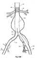
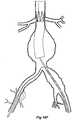
- the vasculaturecomprises an aorta 10 in the region between the renal arteries 12 and the aortic bifurcation 14.
- Common iliac arteries 16 and 18extend down from the aortic bifurcation 14.
- the aorta 10has an aneurysm 20 which extends down into the common iliac artery 18 as far as the bifurcation 22 between the internal iliac artery 24 and the external iliac artery 26.
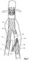
- a twin bifurcated aortic stent graft 40according to one embodiment of the present invention has been deployed into the aorta 10.
- the introduction device which is used to deploy the stent graft into the vasculaturehas been omitted to assist clarity.
- PCT Patent Publication No. WO 98/53761 entitled "A prosthesis and a method deploying a prosthesis”there is disclosed an introducer for a stent graft which is suitable for use with the present invention.
- the proximal end 42 of the bifurcated stent graft 40is engaged into non-aneurysed portion 28 of the aorta 10 just distal of the renal arteries 12.
- stent graft 40has a proximally extending supra-renal exposed stent 44 with barbs 46 engaging the wall of the aorta proximal of the renal arteries to provide a secure position to prevent migration of the stent graft.
- the stent graft 40has a short leg 50 and a long leg 52 extending from the graft bifurcation 54.
- the longer leg 52has a sealing surface 56 at its distal end which engages into a non-aneurysed portion of the external iliac artery 26.
- the longer leg 52has a side arm 60 which in this embodiment is in the form of a corrugated tube extending in a part helical manner from its connection at a fenestration 62 into the longer leg 52.
- the side arm 60extends in a distal direction and helically partly around the longer leg 52 and has a distal end 61 remote from its connection with the longer leg 52 which opens adjacent to the internal iliac artery 24.
- a fenestration 64is placed into the longer leg 52 proximal of the connection of the side arm 60 into the longer leg 52.
- the fenestration 64has a valve arrangement within it to close it off as will be discussed with reference to Figures 3 to 5 .
- an indwelling catheter 66extends through the side arm 60 and out through the valved fenestration 64.
- the indwelling catheterincludes a guide wire 68.
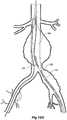
- Figure 2shows the embodiment of Figure 1 but after deployment of a extension piece 70 into the corrugated side arm 60 and deployment of a leg extension 72 into the short leg 50 of the bifurcated stent graft 40 which seals into a non-aneurysed portion of the iliac artery 16.
- United States Patent Application Serial No. 10/962,763 entitled “Introducer for Iliac Side Branch Device” and published as US 2005/0182476discloses an arrangement for using an indwelling catheter to access an internal iliac artery. At this stage the indwelling catheter has been withdrawn and the fenestration 64 is closed off by the valve arrangement.
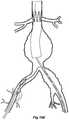
- the extension piece 70seals into a non-aneurysed portion of the internal iliac artery 24.
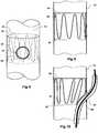
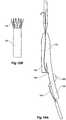
- Figures 3, 4 and 5show a first embodiment of valve arrangement suitable for the present invention.
- the longer leg 52 of the bifurcated stent graft 40 as shown in Figure 1has a fenestration 64 defined by a peripheral resilient ring 80 which is stitched into the tube of the longer leg 52.
- a semi-circular portion of biocompatible graft material 82 and a resilient self-expanding zigzag stent 85which engages with the semi-circular biocompatible graft material 82 and engages it against the inside wall of the longer leg 52 and in particular over the fenestration 64.
- the semi-circular piece 82is stitched by stitching 83 at its proximal end to the inner wall of the longer leg 52.
- the side arm 60extends from a fenestration 62 in the tubular longer leg 52.
- Figure 5shows the embodiment as shown in Figure 4 except that an indwelling catheter 66 and guide wire 68 through the indwelling catheter extend through the side arm 60 and through the fenestration 64 and this lifts the valve 82 off the fenestration 64 against the restoring force of the resilient self expanding stent 85.
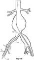
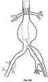
- FIGs 6 and 7show an alternative embodiment of bifurcated stent graft according to the present invention in the vasculature of a patient.
- the vasculature and the bifurcated stent graftare similar to the earlier embodiment shown in Figures 1 and 2 and the same reference numerals are used for corresponding items.
- the vasculaturecomprises an aorta 10 in the region between the renal arteries 12 and the aortic bifurcation 14.
- Common iliac arteries 16 and 18extend down from the aortic bifurcation.
- the aorta 10has an aneurysm 20 which extends down into the common iliac artery 18 so far as the bifurcation 22 between the internal iliac artery 24 and the external iliac artery 26.
- a bifurcated aortic stent graft 40has been deployed into the aorta 10.
- the proximal end 42 of the bifurcated stent graft 40is engaged into non-aneurysed portion 28 of the aorta 10 just distal of the renal arteries 12.
- stent graft 40has a proximally extending supra-renal exposed stent 44 with barbs 46 engaging the wall of the aorta proximal of the renal arteries to provide a secure position to prevent migration of the stent graft.
- the stent graft 40has a short leg 50 and a long leg 52 extending from the graft bifurcation 54.
- the longer leg 52has a sealing surface 56 at its distal end which engages into a non-aneurysed portion of the external iliac artery 26.
- the longer leg 52has a side arm 90 which in this embodiment is in the form of a stented tube extending from a fenestration 92 in the longer leg 52.
- the side arm 90extends in a distal direction and has an end 94 remote from its connection with the longer leg 52 which opens adjacent to the internal iliac artery 24.
- a fenestration 64is placed into the longer leg 52 proximal of the connection of the side arm 90 into the longer leg 52.
- the fenestration 64has a valve arrangement within it to close it off as will be discussed with reference to Figures 8 to 10 .
- an indwelling catheter 66extends through the side arm 90 and out through the valved fenestration 64.
- the indwelling catheterincludes a guide wire 68 therethrough.
- Figure 7shows the embodiment of Figure 6 but after deployment of a extension piece 70 into the side arm 90.
- United States Patent Application Serial No. 10/962,763 entitled “Introducer for Iliac Side Branch Device” and published as US 2005/0182476discloses an arrangement for using an indwelling catheter to access an internal iliac artery. At this stage the indwelling catheter has been withdrawn and the fenestration 64 is closed off by the valve arrangement. The extension piece 70 seals into a non-aneurysed portion of the internal iliac artery 24.
- FIGS 8, 9 and 10show an alternative embodiment of valve arrangement suitable for the present invention.
- the longer leg 52 of the bifurcated stent graft 40 as shown in Figure 6has a fenestration 64 defined by a peripheral resilient ring 80 which is stitched into the tubular wall of the longer leg 52.
- a cylindrical portion of biocompatible graft material 96 and a self-expanding zigzag stent 98which engages with the cylindrical biocompatible graft material 96 and engages it against the inside wall of the longer leg 52 and in particular over the fenestration 64.
- the cylindrical portion of biocompatible graft material 96is stitched by stitching 99 at its proximal end to the inner wall of the longer leg 52.
- Figure 10shows the embodiment as shown in Figure 9 except that an indwelling catheter 66 and guide wire 68 through the catheter extend through the side arm 60 and through the fenestration 64 and this lifts the valve 96 for the fenestration 64.
- FIGS 11 to 14show a further embodiment of valve arrangement suitable for the present invention.
- the longer leg 200 of the bifurcated stent graft 40( Figure 1 ) has a fenestration 202 defined by a peripheral resilient ring 204 which is stitched into the tube of the longer leg 200.
- a self expanding stent 206which has a plurality of struts 208 and bends 210.
- the self expanding stent 206is shown in Figure 12 .
- the self expanding stent 206has a valve member 212 formed from a piece of biocompatible graft material stitched onto spaced apart struts 208 to provide a part cylindrical surface on the self expanding stent 206 to form a valve assembly 214.
- valve member 212Around the lower circumference of the valve member 212 is a portion of resilient wire 213 retained by stitching 21 5 to assist with retaining the part circular shape of the valve member to endure good sealing against the inside surface of the tubular body of the longer leg 200.
- This valve assemblyis stitched into the tubular body of the longer leg 200 by stitching 216 at the bends 210 so that the valve member underlies the fenestration 202 and closes off the fenestration to flow therethrough from inside the longer leg to outside.
- a cross section of the valve at this stageis shown in Figure 13 .
- a side arm 218extends from a fenestration 220 in the tubular longer leg 200.
- the side arm 218is in this embodiment formed from a corrugated graft material.
- Figure 14shows the embodiment as shown in Figure 13 except that an indwelling catheter 66 and guide wire 68 through the indwelling catheter extend through the side arm 218 and through the fenestration 202 and this lifts the valve member 212 off the fenestration 202 against the restoring force of the resilient self expanding stent 206.
- Figure 15A to 15Mshow the various stages of deployment of a stent graft according to one embodiment of the present invention.
- FIG 15Ashows a schematic version of one embodiment of a stent graft according to the present invention loaded onto a delivery device.
- the delivery device 100has a nose cone dilator 102 at its proximal end and a stent graft assembly according to one embodiment of the present invention 104 is mounted onto the deployment device.
- This embodiment of stent graft 104has an helical side arm 106 on the longer leg 108 of the stent graft 104.
- An indwelling catheter 110extends from the deployment device 100 through the helical side arm 106 exiting at valved aperture 112 and extending to a groove 114 in the nose cone dilator 102 outside of the stent graft 104.
- the indwelling catheter 110has a flexible curved proximal end 116.
- FIG. 15BDetail of the tubular side arm 106 and valve arrangement 112 are shown in Figure 15B .
- the tubular side arm 106extends around the longer leg 108 from a fenestration and the indwelling catheter 110 extends into the tubular side arm and out through the valved aperture 112.
- the valved aperture 112has a flap valve 113 on its inside to ensure that the aperture is closed when the indwelling catheter is removed.
- the flap valveis substantially the same as the as the construction shown in Figures 3 to 6 .
- Figure 15Cshows a schematic vasculature of a patient including an aorta 10 renal arteries 12 and an aortic bifurcation 14. Extending from the aortic bifurcation are iliac arteries 16 and 18. The aorta has an aneurysm 20 which extends down the iliac artery to the position of the internal iliac artery 24. The iliac bifurcation 22 defines the bifurcation between the internatal iliac artery 24 and the external iliac artery 26.
- the deployment device 100has been deployed over a guide wire 140 so that its nose cone 102 extends up into the aneurysm 20 and the distal end of the nose cone 102 is substantially adjacent to the aortic bifurcation 14.
- the indwelling catheter and particularly its curved tip 116has been compressed by the sheath 122 into the groove 114 in the nose cone dilator.
- the sheath 122 of the deployment device 100is then withdrawn to release the shorter leg 109 of the stent graft 104. This stage is shown in Figure 15G .
- the indwelling catheteris withdrawn down into the contra-lateral iliac artery 16 and the sheath 122 is withdrawn so that it is distal of the distal end of the side arm 106 while still retaining the distal end of the longer leg 108.
- a dilator and sheath introducer 130is advanced over the guide wire 124 in the contra-lateral iliac artery 16 and the indwelling catheter 110 and extension arm deployment device are tracked over the guide wire 124 so that the nose cone 132 of the sheath introducer enters the valved aperture 112 and tracks over the guide wire 124 into the side arm 106 until it exits the distal end of the side arm 134 as shown in Figure 15J .
- the sheath introducer nose cone 132is then withdrawn leaving the sheath 130 in place.
- the indwelling guide wire 124is still in a through-and-through position.
- another guide wire 136is introduced through the sheath 130 and extended from the sheath 130 to enter into the internal iliac artery 24.
- a side arm deployment deviceis deployed over the guide wire 136 into the internal iliac artery 24 so that balloon expandable covered stent 140 extends into the internal iliac artery 24 from the side arm 106.
- the indwelling guide wire 124is then removed and the position of the distal end of the longer leg 108 is set into the external iliac artery 26 and the balloon expandable covered stent 140 is expanded.
- the sheath 130is then withdrawn and the valve 112 automatically closes.
- a leg extension 144is then placed into the short leg 107 of the graft 104.
- the proximal end 146 of the stent graftis also released from the deployment device 100 such that a portion of the graft seals into a non-aneurysed portion of the aorta 10 distal of the renal arteries 12 while an uncovered suprarenal stent 148 extends over the renal arteries to provide secure fixation.
- Figures 16A to 16Kshow an alternative embodiment of stent graft according to the present invention and the process of deploying such a stent graft in the vasculature of a patient.
- the stent graft in this embodimentcomprises a two piece body with a proximal portion 150 and a distal portion 1 52 which when joined together into the vasculature of the patient provide a composite stent graft.
- the proximal portion 150has the proximally extending suprarenal stents 154 and the distal portion 152 is bifurcated with a shorter leg 156 and longer leg 158.
- the longer leg 158has the helical side arm 160 and the valved aperture 162 through which the indwelling catheter 164 extends.
- the process of deployment of the stent graft of this embodimentis substantially similar to that shown in Figures 15C to 15M except that, as shown in Figure 16C , as a first stage the proximal portion 150 is deployed and released into the aorta. Subsequently a separate device 170 with an indwelling catheter 164 is introduced which carries the distal portion 152 and the process of snaring the indwelling guide wire, release of the main stent graft and deployment of a side arm extension into the internal iliac artery as shown in Figures 16D to 16J is substantially the same as shown in Figures 15C to 15L .
- the final stage as shown in Figure 16K of the deployment of the two piece stent graftincludes release of the distal portion 152 inside the proximal portion 150 and the deployment of a leg extension 172 into the short leg 156 and release of the distal end of the longer leg 158.
- an alternative embodiment access for deployment into the internal iliac arterymaybe by a brachial approach and in such case the indwelling catheter in the side arm may extend through the main lumen of the stent graft and the valved aperture may not be necessary in such an embodiment.
Landscapes
- Health & Medical Sciences (AREA)
- Biomedical Technology (AREA)
- Engineering & Computer Science (AREA)
- Life Sciences & Earth Sciences (AREA)
- Cardiology (AREA)
- General Health & Medical Sciences (AREA)
- Heart & Thoracic Surgery (AREA)
- Animal Behavior & Ethology (AREA)
- Public Health (AREA)
- Veterinary Medicine (AREA)
- Vascular Medicine (AREA)
- Transplantation (AREA)
- Oral & Maxillofacial Surgery (AREA)
- Surgery (AREA)
- Pulmonology (AREA)
- Gastroenterology & Hepatology (AREA)
- Nuclear Medicine, Radiotherapy & Molecular Imaging (AREA)
- Medical Informatics (AREA)
- Molecular Biology (AREA)
- Prostheses (AREA)
- Media Introduction/Drainage Providing Device (AREA)
- Materials For Medical Uses (AREA)
Description
- This invention relates to a medical device and more particularly a device which can be deployed by endovascular means into the vasculature of a patient.
- There have been proposed bifurcated endovascular devices which can be deployed into the vasculature, particularly in the region of the aortic bifurcation, so that an aneurysm in the aorta can be bridged by placement of the endovascular device with a proximal portion which seals into a non-aneurysed portion of the aorta adjacent to the renal arteries, a first leg which extends down one iliac artery to a non-aneurysed portion of the iliac artery and another short leg into which a leg extension may be placed to extend into a non-aneurysed portion of the contra-lateral iliac artery.
- There can be problems, however, if the aneurysm of the aorta extends down into one or other of the iliac arteries. Each of the common iliac arteries branches into the internal and external iliac arteries and it is necessary in such a situation that a blood flow path can be directed through an endovascular stent graft into each of these arteries.
- The object of this invention is to provide a single endovascularly deployed medical device which can solve this problem or at least provide a physician with a useful alternative.
US 2002/169497 A1 discloses a stent graft comprising a tubular body of a biocompatible graft material defining a main lumen therethrough, an aperture defining a fenestration in the tubular body and a valve arrangement to prevent fluid flow through the aperture.WO 2004/089249 andUS 2005/0059923 also disclose stent devices with valve arrangements.- Throughout this specification the term distal with respect to a portion of the aorta, a deployment device or a prosthesis means the end of the aorta, deployment device or prosthesis further away in the direction of blood flow away from the heart and the term proximal means the portion of the aorta, deployment device or end of the prosthesis nearer to the heart. When applied to other vessels similar terms such as caudal and cranial should be understood.
- A stent graft according to the present invention is defined in claim 1.
- Preferred embodiments of the present invention have a tubular body of a biocompatible graft material defining a main lumen therethrough, a bifurcation in the tubular body at one end thereof and a first leg and a second leg extending from the bifurcation, the first leg being a long leg and the second leg being a short leg, the first and second legs having respective first and second lumens therethrough and the first and second lumens being in fluid communication with the main lumen, with the first long leg comprising a side arm with a side arm lumen therethrough and the side arm lumen being in fluid communication with the first leg lumen, whereby the stent graft can be deployed into the vasculature of a patient with the tubular body being in an aorta of the patient, the first leg extending down an iliac artery, the second leg being directed towards a contralateral iliac artery and the side arm on the first leg directed to an internal artery of the iliac artery.
- In an alternative embodiment the side arm comprises a tube of biocompatible graft material and at least one self expanding stent on the tube of biocompatible graft material. Co-pending United States Patent Application Serial No.
11/231,621 US 2006/0095118 discloses side arm tubes suitable for the present invention. - Preferably the first leg includes an aperture or fenestration proximally of the side arm and a valve arrangement to prevent fluid flow through the aperture from inside of the leg to outside of the leg.
- Preferably the aperture includes a resilient reinforcement ring around the aperture.
- The valve arrangement can comprise a sleeve of a biocompatible graft material within the first leg and a self expanding stent within the sleeve, the sleeve being fastened at its proximal end to the first leg proximal of the aperture and the self expanding stent being fastened to the sleeve, whereby the self expanding stent forces the sleeve against the inner surface of the first leg around the aperture to prevent fluid flow through the aperture from inside of the leg to outside of the leg.
- In one preferred embodiment the sleeve of a biocompatible graft material comprises a cylindrical form. In an alternative embodiment the sleeve of a biocompatible graft material comprises a semi-cylindrical form.
- Alternatively the valve can be formed from a self expanding stent to which a part cylindrical portion of biocompatible graft material is stitched along spaced apart struts of the self expanding stent. These two components together can form a valve assembly which can be stitched into the longer leg of the stent graft.
- The valve assembly can further include a semi-circular resilient wire around the distal end of the part cylindrical portion of biocompatible graft material forming the valve member. This semi-circular resilient wire around the distal end of the part cylindrical portion of biocompatible graft material will assist with sealing off the fenestration by ensuring that the distal end of the valve member is held against the inside of the wall of the longer first leg of the stent graft.
- The biocompatible graft material can include polytetrafluoroethylene, Dacron, polyamide or any other suitable biocompatible graft material.
- While Dacron, expanded polytetrafluoroethylene (ePTFE), or other synthetic biocompatible materials can be used for the tubular graft material for the stent graft, a naturally occurring biomaterial, such as collagen, is highly desirable, particularly a specially derived collagen material known as an extracellular matrix (ECM), such as small intestinal submucosa (SIS). Besides SIS, examples of ECM's include pericardium, stomach submucosa, liver basement membrane, urinary bladder submucosa, tissue mucosa, and dura mater.
- SIS is particularly useful, and can be made in the fashion described in
Badylak et al., US Patent 4,902,508 ; Intestinal Collagen Layer described inUS Patent 5,733,337 to Carr and in17 Nature Biotechnology 1083 (Nov. 1999);Cook et al., PCT Publication WO 98/22158, dated 28 May 1998 PCT/US97/14855 US Patents 5,968,096 ;5,955,110 ;5,885,619 ; and5,711,969 . In addition to xenogenic biomaterials, such as SIS, autologous tissue can be harvested as well, for use in forming the tubular graft material. Additionally Elastin or Elastin-Like Polypetides (ELPs) and the like offer potential as a material to fabricate the tubular graft material to form a device with exceptional biocompatibility. - SIS is available from Cook Biotech, West Lafayette, Indiana, USA.
- It will be seen that by this invention there is provided a stent graft which has a main bifurcation to allow access into each of the iliac arteries and in one of the legs extending from the bifurcation there is a further bifurcation or branch which will enable access into the internal iliac artery. There is some advantage in having a double or twin bifurcation stent graft.
- As discussed above there is preferably a valve arrangement proximal of the side arm or side branch of the iliac leg of the bifurcated stent graft. The valve allows an indwelling catheter to be provided through the sidearm in the iliac artery at the time of deployment to assist with deployment of leg extension into the internal iliac artery.
- United States Patent Application Serial No.
10/962,763 US 2005/0182476 discloses an arrangement for using an indwelling catheter to access an internal iliac artery. In this case the indwelling catheter can be extended and its guide wire snared from the contra-lateral artery and the leg extension placed into the internal iliac artery before the leg extension is placed into the iliac artery. According to the invention, a stent graft comprises a tubular body of a biocompatible graft material defining a main lumen therethrough an aperture defining a fenestration in the tubular body and a valve arrangement to prevent fluid flow through the aperture. - Preferably the aperture includes a resilient reinforcement ring around the aperture. The valve arrangement comprises a sleeve of a biocompatible graft material within the tubular body and a self expanding stent within the sleeve, the sleeve being fastened at its proximal end to the first leg proximal of the aperture and the self expanding stent being fastened to the sleeve, whereby the self expanding stent forces the sleeve against the inner surface of the tubular body around the aperture to prevent fluid flow through the aperture.
- The sleeve of a biocompatible graft material can comprise a cylindrical form or alternatively a semi-cylindrical form.
- In one embodiment the valve arrangement comprises a valve assembly comprising a self expanding stent to which a part cylindrical portion of biocompatible graft material is stitched along spaced apart struts of the self expanding stent.
- The valve assembly can further comprise a semi-circular resilient wire around the distal end of the part cylindrical portion of biocompatible graft material forming the valve member.
- This then generally describes the invention but to assist with understanding reference will now be made to the accompanying drawings which show further embodiments of the invention.
- In the drawings;
Figure 1 shows a first embodiment of stent graft according to the invention as it would be deployed into the vasculature before placement of an iliac side branch;Figure 2 shows the embodiment ofFigure 1 with the side branch installed into the internal iliac artery and the leg extension in the contralateral iliac artery;Figure 3 shows a schematic view of part of the leg of the stent graft of the present invention in particular showing one embodiment of the valve arrangement;Figure 4 shows a cross-section of embodiment shown inFigure 3 ;Figure 5 shows a same view asFigure 4 except with the indwelling catheter extending through the corrugated side arm and valve;Figure 6 shows an alternative embodiment of stent graft deployed into a schematic vasculature with an alternative arrangement of side arm;Figure 7 shows embodiment ofFigure 6 at the stage where the indwelling catheter has been snared and pulled down the contralateral artery and the indwelling catheter has been used to deploy an extension piece into internal iliac artery;Figure 8 shows an alternative embodiment of valve arrangement suitable for the embodiment of stent graft shown inFigures 6 and7 ;Figure 9 shown a cross-section thought the valve arrangement ofFigure 8 ;Figure 10 shows the valve arrangement ofFigures 8 and 9 with an indwelling catheter extending through it;Figure 11 shows an alternative embodiment of valve arrangement suitable for the embodiment of stent graft shown inFigures 6 and7 ;Figure 12 shown a detail of the valve arrangement ofFigure 11 showing the self expanding stent with a valve member mounted onto it;Figure 13 shown a cross-section thought valve arrangement ofFigure 11 ;Figure 14 shows the valve arrangement ofFigures 11 and 13 with an indwelling catheter extending through it:Figure 15A to 15M show the various stages of deployment of a stent graft according to one embodiment of the present invention; andFigure 16A to 16K show the various stages of deployment of a stent graft according to another embodiment of the present invention.- Looking more closely at the drawings and in particular
Figures 1 and2 it will be seen that a schematic view of part of the vascular arrangement of a patient is illustrated incorporating a stent graft according to the present invention. - The vasculature comprises an
aorta 10 in the region between therenal arteries 12 and theaortic bifurcation 14. Commoniliac arteries aortic bifurcation 14. Theaorta 10 has ananeurysm 20 which extends down into the commoniliac artery 18 as far as thebifurcation 22 between the internaliliac artery 24 and the externaliliac artery 26. - To traverse the aneurysm 20 a twin bifurcated
aortic stent graft 40 according to one embodiment of the present invention has been deployed into theaorta 10. In this drawing the introduction device which is used to deploy the stent graft into the vasculature has been omitted to assist clarity. In our earlier patent application,PCT Patent Publication No. WO 98/53761 proximal end 42 of thebifurcated stent graft 40 is engaged intonon-aneurysed portion 28 of theaorta 10 just distal of therenal arteries 12. In thisembodiment stent graft 40 has a proximally extending supra-renalexposed stent 44 withbarbs 46 engaging the wall of the aorta proximal of the renal arteries to provide a secure position to prevent migration of the stent graft. Thestent graft 40 has ashort leg 50 and along leg 52 extending from thegraft bifurcation 54. Thelonger leg 52 has a sealingsurface 56 at its distal end which engages into a non-aneurysed portion of the externaliliac artery 26. - The
longer leg 52 has aside arm 60 which in this embodiment is in the form of a corrugated tube extending in a part helical manner from its connection at afenestration 62 into thelonger leg 52. Theside arm 60 extends in a distal direction and helically partly around thelonger leg 52 and has adistal end 61 remote from its connection with thelonger leg 52 which opens adjacent to the internaliliac artery 24. - A
fenestration 64 is placed into thelonger leg 52 proximal of the connection of theside arm 60 into thelonger leg 52. Thefenestration 64 has a valve arrangement within it to close it off as will be discussed with reference toFigures 3 to 5 . - During deployment of the stent graft into the vasculature of a patient an
indwelling catheter 66 extends through theside arm 60 and out through thevalved fenestration 64. The indwelling catheter includes aguide wire 68. Figure 2 shows the embodiment ofFigure 1 but after deployment of aextension piece 70 into thecorrugated side arm 60 and deployment of aleg extension 72 into theshort leg 50 of thebifurcated stent graft 40 which seals into a non-aneurysed portion of theiliac artery 16. United States Patent Application Serial No.10/962,763 US 2005/0182476 discloses an arrangement for using an indwelling catheter to access an internal iliac artery. At this stage the indwelling catheter has been withdrawn and thefenestration 64 is closed off by the valve arrangement.- The
extension piece 70 seals into a non-aneurysed portion of the internaliliac artery 24. - The process of deployment of a stent graft according to this embodiment of the invention will be discussed with reference to
Figures 15A to 15M . Figures 3, 4 and 5 show a first embodiment of valve arrangement suitable for the present invention.- In this embodiment the
longer leg 52 of thebifurcated stent graft 40 as shown inFigure 1 has afenestration 64 defined by a peripheralresilient ring 80 which is stitched into the tube of thelonger leg 52. Inside the longer leg is a semi-circular portion ofbiocompatible graft material 82 and a resilient self-expandingzigzag stent 85 which engages with the semi-circularbiocompatible graft material 82 and engages it against the inside wall of thelonger leg 52 and in particular over thefenestration 64. By this arrangement thefenestration 64 is held in a closed configuration. Thesemi-circular piece 82 is stitched by stitching 83 at its proximal end to the inner wall of thelonger leg 52. - Substantially opposite to the
fenestration 64 in the tubularlonger leg 52 theside arm 60 extends from afenestration 62 in the tubularlonger leg 52. Figure 5 shows the embodiment as shown inFigure 4 except that anindwelling catheter 66 andguide wire 68 through the indwelling catheter extend through theside arm 60 and through thefenestration 64 and this lifts thevalve 82 off thefenestration 64 against the restoring force of the resilientself expanding stent 85.Figures 6 and7 show an alternative embodiment of bifurcated stent graft according to the present invention in the vasculature of a patient. The vasculature and the bifurcated stent graft are similar to the earlier embodiment shown inFigures 1 and2 and the same reference numerals are used for corresponding items.- The vasculature comprises an
aorta 10 in the region between therenal arteries 12 and theaortic bifurcation 14. Commoniliac arteries aorta 10 has ananeurysm 20 which extends down into the commoniliac artery 18 so far as thebifurcation 22 between the internaliliac artery 24 and the externaliliac artery 26. - To traverse the aneurysm a bifurcated
aortic stent graft 40 has been deployed into theaorta 10. Theproximal end 42 of thebifurcated stent graft 40 is engaged intonon-aneurysed portion 28 of theaorta 10 just distal of therenal arteries 12. In thisembodiment stent graft 40 has a proximally extending supra-renalexposed stent 44 withbarbs 46 engaging the wall of the aorta proximal of the renal arteries to provide a secure position to prevent migration of the stent graft. Thestent graft 40 has ashort leg 50 and along leg 52 extending from thegraft bifurcation 54. Thelonger leg 52 has a sealingsurface 56 at its distal end which engages into a non-aneurysed portion of the externaliliac artery 26. - The
longer leg 52 has aside arm 90 which in this embodiment is in the form of a stented tube extending from afenestration 92 in thelonger leg 52. Theside arm 90 extends in a distal direction and has anend 94 remote from its connection with thelonger leg 52 which opens adjacent to the internaliliac artery 24. - A
fenestration 64 is placed into thelonger leg 52 proximal of the connection of theside arm 90 into thelonger leg 52. Thefenestration 64 has a valve arrangement within it to close it off as will be discussed with reference toFigures 8 to 10 . - During deployment of the stent graft into the vasculature of a patient an
indwelling catheter 66 extends through theside arm 90 and out through thevalved fenestration 64. The indwelling catheter includes aguide wire 68 therethrough. Figure 7 shows the embodiment ofFigure 6 but after deployment of aextension piece 70 into theside arm 90. United States Patent Application Serial No.10/962,763 US 2005/0182476 discloses an arrangement for using an indwelling catheter to access an internal iliac artery. At this stage the indwelling catheter has been withdrawn and thefenestration 64 is closed off by the valve arrangement. Theextension piece 70 seals into a non-aneurysed portion of the internaliliac artery 24.Figures 8, 9 and 10 show an alternative embodiment of valve arrangement suitable for the present invention.- In this embodiment of valve the
longer leg 52 of thebifurcated stent graft 40 as shown inFigure 6 has afenestration 64 defined by a peripheralresilient ring 80 which is stitched into the tubular wall of thelonger leg 52. Inside the longer leg is a cylindrical portion ofbiocompatible graft material 96 and a self-expandingzigzag stent 98 which engages with the cylindricalbiocompatible graft material 96 and engages it against the inside wall of thelonger leg 52 and in particular over thefenestration 64. By this arrangement thefenestration 64 is held in a closed configuration. The cylindrical portion ofbiocompatible graft material 96 is stitched by stitching 99 at its proximal end to the inner wall of thelonger leg 52. Figure 10 shows the embodiment as shown inFigure 9 except that anindwelling catheter 66 andguide wire 68 through the catheter extend through theside arm 60 and through thefenestration 64 and this lifts thevalve 96 for thefenestration 64.Figures 11 to 14 show a further embodiment of valve arrangement suitable for the present invention.- In this embodiment the
longer leg 200 of the bifurcated stent graft 40 (Figure 1 ) has afenestration 202 defined by a peripheralresilient ring 204 which is stitched into the tube of thelonger leg 200. Inside the longer leg is aself expanding stent 206 which has a plurality ofstruts 208 and bends 210. Theself expanding stent 206 is shown inFigure 12 . - The
self expanding stent 206 has avalve member 212 formed from a piece of biocompatible graft material stitched onto spaced apart struts 208 to provide a part cylindrical surface on theself expanding stent 206 to form avalve assembly 214. - Around the lower circumference of the
valve member 212 is a portion ofresilient wire 213 retained by stitching 21 5 to assist with retaining the part circular shape of the valve member to endure good sealing against the inside surface of the tubular body of thelonger leg 200. - This valve assembly is stitched into the tubular body of the
longer leg 200 by stitching 216 at thebends 210 so that the valve member underlies thefenestration 202 and closes off the fenestration to flow therethrough from inside the longer leg to outside. A cross section of the valve at this stage is shown inFigure 13 . - Substantially opposite to the
fenestration 202 in the tubular longer leg 200 aside arm 218 extends from afenestration 220 in the tubularlonger leg 200. Theside arm 218 is in this embodiment formed from a corrugated graft material. Figure 14 shows the embodiment as shown inFigure 13 except that anindwelling catheter 66 andguide wire 68 through the indwelling catheter extend through theside arm 218 and through thefenestration 202 and this lifts thevalve member 212 off thefenestration 202 against the restoring force of the resilientself expanding stent 206.Figure 15A to 15M show the various stages of deployment of a stent graft according to one embodiment of the present invention.Figure 15A shows a schematic version of one embodiment of a stent graft according to the present invention loaded onto a delivery device. For convenience the sheath of the delivery device has been withdrawn to show the assembly inside it. Thedelivery device 100 has anose cone dilator 102 at its proximal end and a stent graft assembly according to one embodiment of thepresent invention 104 is mounted onto the deployment device. This embodiment ofstent graft 104 has anhelical side arm 106 on thelonger leg 108 of thestent graft 104. Anindwelling catheter 110 extends from thedeployment device 100 through thehelical side arm 106 exiting atvalved aperture 112 and extending to agroove 114 in thenose cone dilator 102 outside of thestent graft 104. Theindwelling catheter 110 has a flexible curvedproximal end 116.- Detail of the
tubular side arm 106 andvalve arrangement 112 are shown inFigure 15B . Thetubular side arm 106 extends around thelonger leg 108 from a fenestration and theindwelling catheter 110 extends into the tubular side arm and out through thevalved aperture 112. Thevalved aperture 112 has aflap valve 113 on its inside to ensure that the aperture is closed when the indwelling catheter is removed. The flap valve is substantially the same as the as the construction shown inFigures 3 to 6 . Figure 15C shows a schematic vasculature of a patient including anaorta 10renal arteries 12 and anaortic bifurcation 14. Extending from the aortic bifurcation areiliac arteries aneurysm 20 which extends down the iliac artery to the position of the internaliliac artery 24. Theiliac bifurcation 22 defines the bifurcation between the internataliliac artery 24 and the externaliliac artery 26.- As shown in
Figure 15C thedeployment device 100 has been deployed over aguide wire 140 so that itsnose cone 102 extends up into theaneurysm 20 and the distal end of thenose cone 102 is substantially adjacent to theaortic bifurcation 14. As shown in the detail inFigure 15C the indwelling catheter and particularly itscurved tip 116 has been compressed by thesheath 122 into thegroove 114 in the nose cone dilator. - As shown in
Figure 15D thesheath 122 of the deployment device has been withdrawn slightly to release thecurved tip 116 of theindwelling catheter 110 and theindwelling guide wire 124 from theindwelling catheter 110 has been extended. Because of the curved end of the indwelling catheter theindwelling guide wire 124 has extended down the contra-lateraliliac artery 16. Asnare catheter 128 has been deployed into the contra-lateral common iliac artery and asnare 130 of thesnare catheter 128 has been extended to grasp theguide wire 124. Theguide wire 124 is extracted via thesnare catheter 128 so that it becomes a through-and-through guide wire. It is important at this stage to ensure there is slack maintained in the guide wire at the aortic bifurcation to prevent damage to the aortic bifurcation. This position is shown inFigure 15E . - The use of and indwelling catheter with a curved tip to facilitate snaring from a contralateral iliac artery is taught in
US Patent Application Serial No. 11/600,655 entitled 'Stent Graft Introducer' and published asUS 2007/0123910 . As shown inFigure 15F thedeployment device 100 in then advanced so that thenose cone dilator 102 is proximal of therenal arteries 12. This draws theindwelling guide wire 124 also up into theaorta 10. - The
sheath 122 of thedeployment device 100 is then withdrawn to release theshorter leg 109 of thestent graft 104. This stage is shown inFigure 15G . - As shown in
Figure 15H the indwelling catheter is withdrawn down into the contra-lateraliliac artery 16 and thesheath 122 is withdrawn so that it is distal of the distal end of theside arm 106 while still retaining the distal end of thelonger leg 108. - As shown in
Figure 15I a dilator andsheath introducer 130 is advanced over theguide wire 124 in the contra-lateraliliac artery 16 and theindwelling catheter 110 and extension arm deployment device are tracked over theguide wire 124 so that thenose cone 132 of the sheath introducer enters thevalved aperture 112 and tracks over theguide wire 124 into theside arm 106 until it exits the distal end of theside arm 134 as shown inFigure 15J . The sheathintroducer nose cone 132 is then withdrawn leaving thesheath 130 in place. At this stage theindwelling guide wire 124 is still in a through-and-through position. As shown inFigure 15K , anotherguide wire 136 is introduced through thesheath 130 and extended from thesheath 130 to enter into the internaliliac artery 24. - As shown in
Figure 15L a side arm deployment device is deployed over theguide wire 136 into the internaliliac artery 24 so that balloon expandable coveredstent 140 extends into the internaliliac artery 24 from theside arm 106. As shown inFigure 15M , theindwelling guide wire 124 is then removed and the position of the distal end of thelonger leg 108 is set into the externaliliac artery 26 and the balloon expandable coveredstent 140 is expanded. Thesheath 130 is then withdrawn and thevalve 112 automatically closes. Aleg extension 144 is then placed into theshort leg 107 of thegraft 104. Theproximal end 146 of the stent graft is also released from thedeployment device 100 such that a portion of the graft seals into a non-aneurysed portion of theaorta 10 distal of therenal arteries 12 while an uncoveredsuprarenal stent 148 extends over the renal arteries to provide secure fixation. Figures 16A to 16K show an alternative embodiment of stent graft according to the present invention and the process of deploying such a stent graft in the vasculature of a patient.- The stent graft in this embodiment comprises a two piece body with a
proximal portion 150 and a distal portion 1 52 which when joined together into the vasculature of the patient provide a composite stent graft. Theproximal portion 150 has the proximally extendingsuprarenal stents 154 and thedistal portion 152 is bifurcated with ashorter leg 156 andlonger leg 158. Thelonger leg 158 has thehelical side arm 160 and thevalved aperture 162 through which theindwelling catheter 164 extends. - The process of deployment of the stent graft of this embodiment is substantially similar to that shown in
Figures 15C to 15M except that, as shown inFigure 16C , as a first stage theproximal portion 150 is deployed and released into the aorta. Subsequently aseparate device 170 with anindwelling catheter 164 is introduced which carries thedistal portion 152 and the process of snaring the indwelling guide wire, release of the main stent graft and deployment of a side arm extension into the internal iliac artery as shown inFigures 16D to 16J is substantially the same as shown inFigures 15C to 15L . The final stage as shown inFigure 16K of the deployment of the two piece stent graft includes release of thedistal portion 152 inside theproximal portion 150 and the deployment of aleg extension 172 into theshort leg 156 and release of the distal end of thelonger leg 158. - It will be realised that an alternative embodiment access for deployment into the internal iliac artery maybe by a brachial approach and in such case the indwelling catheter in the side arm may extend through the main lumen of the stent graft and the valved aperture may not be necessary in such an embodiment.
- Throughout this specification various indications have been given as to the scope of invention but invention not limited to any one of these but may reside in two or more of these combined together. The examples are given for illustration only and not for limitations.
Claims (9)
- A stent graft (40) comprising a tubular body (52, 200) of a biocompatible graft material defining a lumen therethrough and having an aperture defining a fenestration (64) in the tubular body, the fenestration having a valve arrangement (82) wherein the valve arrangement is capable of preventing fluid flow through the aperture from inside of the tubular body to outside of the tubular body,characterised in that the valve arrangement comprises a sleeve (82, 96) of a biocompatible graft material within the tubular body and a self expanding stent (85, 98) within the sleeve, the sleeve being fastened at its proximal end to the tubular body (52) proximal of the aperture and the self expanding stent being fastened to the sleeve, whereby the self expanding stent forces the sleeve against the inner surface of the tubular body around the aperture to prevent fluid flow through the aperture.
- A stent graft (40) as in Claim 1, wherein the aperture includes a resilient reinforcement ring (80) around the aperture.
- A stent graft (40) as in Claim 1 or 2, wherein the sleeve (96) of a biocompatible graft material comprises a cylindrical form.
- A stent graft (40) as in Claim 1 or 2, wherein the sleeve (82) of a biocompatible graft material comprises a semi-cylindrical form.
- A stent graft (40) as in Claim 1, wherein a part cylindrical portion (212) of biocompatible graft material forming the valve member is stitched along spaced apart struts (208) of the self expanding stent (206).
- A stent graft (40) as in Claim 5 wherein the valve assembly further comprises a semi-circular resilient wire (213) around the distal end of the part cylindrical portion (212) of biocompatible graft material.
- A stent graft (40) as in any preceding claim wherein the stent graft comprises a main tubular body defining a main lumen therethrough and having a bifurcation (54) at one end thereof, and a first leg (52, 200) and a second leg (50) extending from the bifurcation, the first leg constituting said first-mentioned tubular body and being a long leg and the second leg being a short leg, the first and second legs having respective first and second lumens therethrough and the first and second lumens being in fluid communication with the main lumen, and the first leg comprising a side arm (60) with a side arm lumen therethrough and the side arm lumen being in fluid communication with the first leg lumen, wherein the fenestration (64) is provided in the first leg proximally of the side arm (60).
- A stent graft (40) as in Claim 7, wherein the side arm (60) comprises a tube of corrugated biocompatible graft material and the tube extends part helically around the first leg (52).
- A stent graft (40) as in Claim 7 wherein the side arm (60) comprises a tube of biocompatible graft material and at least one self expanding stent on the tube of biocompatible graft material.
Applications Claiming Priority (2)
| Application Number | Priority Date | Filing Date | Title |
|---|---|---|---|
| US79328206P | 2006-04-19 | 2006-04-19 | |
| PCT/US2007/009665WO2007124053A1 (en) | 2006-04-19 | 2007-04-19 | Twin bifurcated stent graft |
Publications (2)
| Publication Number | Publication Date |
|---|---|
| EP2007313A1 EP2007313A1 (en) | 2008-12-31 |
| EP2007313B1true EP2007313B1 (en) | 2018-05-16 |
Family
ID=38353445
Family Applications (1)
| Application Number | Title | Priority Date | Filing Date |
|---|---|---|---|
| EP07755802.1AActiveEP2007313B1 (en) | 2006-04-19 | 2007-04-19 | Stent graft |
Country Status (7)
| Country | Link |
|---|---|
| US (2) | US9707113B2 (en) |
| EP (1) | EP2007313B1 (en) |
| JP (2) | JP2009534104A (en) |
| CN (1) | CN101484090B (en) |
| AU (1) | AU2007240703C1 (en) |
| CA (1) | CA2649705C (en) |
| WO (1) | WO2007124053A1 (en) |
Cited By (15)
| Publication number | Priority date | Publication date | Assignee | Title |
|---|---|---|---|---|
| US10856984B2 (en) | 2017-08-25 | 2020-12-08 | Neovasc Tiara Inc. | Sequentially deployed transcatheter mitral valve prosthesis |
| US10940001B2 (en) | 2012-05-30 | 2021-03-09 | Neovasc Tiara Inc. | Methods and apparatus for loading a prosthesis onto a delivery system |
| US11311376B2 (en) | 2019-06-20 | 2022-04-26 | Neovase Tiara Inc. | Low profile prosthetic mitral valve |
| US11357622B2 (en) | 2016-01-29 | 2022-06-14 | Neovase Tiara Inc. | Prosthetic valve for avoiding obstruction of outflow |
| US11389291B2 (en) | 2013-04-04 | 2022-07-19 | Neovase Tiara Inc. | Methods and apparatus for delivering a prosthetic valve to a beating heart |
| US11413139B2 (en) | 2011-11-23 | 2022-08-16 | Neovasc Tiara Inc. | Sequentially deployed transcatheter mitral valve prosthesis |
| US11419720B2 (en) | 2010-05-05 | 2022-08-23 | Neovasc Tiara Inc. | Transcatheter mitral valve prosthesis |
| US11464631B2 (en) | 2016-11-21 | 2022-10-11 | Neovasc Tiara Inc. | Methods and systems for rapid retraction of a transcatheter heart valve delivery system |
| US11491006B2 (en) | 2019-04-10 | 2022-11-08 | Neovasc Tiara Inc. | Prosthetic valve with natural blood flow |
| US11497602B2 (en) | 2012-02-14 | 2022-11-15 | Neovasc Tiara Inc. | Methods and apparatus for engaging a valve prosthesis with tissue |
| US11602429B2 (en) | 2019-04-01 | 2023-03-14 | Neovasc Tiara Inc. | Controllably deployable prosthetic valve |
| US11737872B2 (en) | 2018-11-08 | 2023-08-29 | Neovasc Tiara Inc. | Ventricular deployment of a transcatheter mitral valve prosthesis |
| US11779742B2 (en) | 2019-05-20 | 2023-10-10 | Neovasc Tiara Inc. | Introducer with hemostasis mechanism |
| US11998447B2 (en) | 2019-03-08 | 2024-06-04 | Neovasc Tiara Inc. | Retrievable prosthesis delivery system |
| US12109111B2 (en) | 2015-12-15 | 2024-10-08 | Neovasc Tiara Inc. | Transseptal delivery system |
Families Citing this family (88)
| Publication number | Priority date | Publication date | Assignee | Title |
|---|---|---|---|---|
| US7147661B2 (en) | 2001-12-20 | 2006-12-12 | Boston Scientific Santa Rosa Corp. | Radially expandable stent |
| US8308797B2 (en) | 2002-01-04 | 2012-11-13 | Colibri Heart Valve, LLC | Percutaneously implantable replacement heart valve device and method of making same |
| US9125733B2 (en)* | 2003-01-14 | 2015-09-08 | The Cleveland Clinic Foundation | Branched vessel endoluminal device |
| WO2006127412A1 (en)* | 2005-05-20 | 2006-11-30 | The Cleveland Clinic Foundation | Apparatus and methods for repairing the function of a diseased valve and method for making same |
| AU2007240703C1 (en)* | 2006-04-19 | 2012-06-14 | Cleveland Clinic Foundation | Twin bifurcated stent graft |
| WO2008057568A1 (en)* | 2006-11-07 | 2008-05-15 | William A. Cook Australia Pty. Ltd | Fenestrations for stent graft arrangements and stent graft including the same |
| WO2009062264A1 (en)* | 2007-11-15 | 2009-05-22 | Endogad Research Pty Limited | Hybrid intraluminal device |
| GB0803302D0 (en)* | 2008-02-22 | 2008-04-02 | Barts & London Nhs Trust | Blood vessel prosthesis and delivery apparatus |
| CA3009244C (en) | 2009-06-23 | 2020-04-28 | Endospan Ltd. | Vascular prostheses for treating aneurysms |
| WO2011004374A1 (en) | 2009-07-09 | 2011-01-13 | Endospan Ltd. | Apparatus for closure of a lumen and methods of using the same |
| US9095456B2 (en) | 2009-10-13 | 2015-08-04 | Cook Medical Technologies Llc | Paraplegia prevention stent graft |
| EP3034036B1 (en) | 2009-10-13 | 2019-09-11 | Cook Medical Technologies LLC | Paraplegia prevention stent graft |
| CN102740807B (en) | 2009-11-30 | 2015-11-25 | 恩多斯潘有限公司 | Multi-component stent-graft system for implantation into vessels with multiple branches |
| EP2509535B1 (en) | 2009-12-08 | 2016-12-07 | Endospan Ltd | Endovascular stent-graft system with fenestrated and crossing stent-grafts |
| US9468517B2 (en) | 2010-02-08 | 2016-10-18 | Endospan Ltd. | Thermal energy application for prevention and management of endoleaks in stent-grafts |
| US20110208289A1 (en)* | 2010-02-25 | 2011-08-25 | Endospan Ltd. | Flexible Stent-Grafts |
| ES2766450T3 (en)* | 2010-03-04 | 2020-06-12 | Terumo Corp | Artificial blood vessel |
| JP5936610B2 (en) | 2010-06-28 | 2016-06-22 | コリブリ ハート バルブ エルエルシーColibri Heart Valve Llc | Device for intracavity delivery of an intravascular injection device |
| JP5944914B2 (en) | 2010-11-15 | 2016-07-05 | エンドバスキュラー ディベロップメント アクティエボラーグ | Assembly with guide wire and fixator for attachment to a blood vessel |
| US8535371B2 (en) | 2010-11-15 | 2013-09-17 | Endovascular Development AB | Method of positioning a tubular element in a blood vessel of a person |
| AU2011343755A1 (en) | 2010-12-14 | 2013-06-06 | Colibri Heart Valve Llc | Percutaneously deliverable heart valve including folded membrane cusps with integral leaflets |
| CA2826022A1 (en) | 2011-02-03 | 2012-08-09 | Endospan Ltd. | Implantable medical devices constructed of shape memory material |
| WO2012111006A1 (en) | 2011-02-17 | 2012-08-23 | Endospan Ltd. | Vascular bands and delivery systems therefor |
| AU2011200858B1 (en) | 2011-02-28 | 2012-04-05 | Cook Medical Technologies Llc | Stent graft with valve arrangement |
| WO2012117395A1 (en) | 2011-03-02 | 2012-09-07 | Endospan Ltd. | Reduced-strain extra- vascular ring for treating aortic aneurysm |
| EP3583916B1 (en) | 2011-04-28 | 2023-12-06 | Cook Medical Technologies LLC | Apparatus for facilitating deployment of an endoluminal prosthesis |
| AU2011202120B1 (en) | 2011-05-09 | 2012-09-13 | Cook Medical Technologies Llc | Paraplegia prevention valve for stent grafts |
| US8574287B2 (en) | 2011-06-14 | 2013-11-05 | Endospan Ltd. | Stents incorporating a plurality of strain-distribution locations |
| US8951298B2 (en) | 2011-06-21 | 2015-02-10 | Endospan Ltd. | Endovascular system with circumferentially-overlapping stent-grafts |
| US9254209B2 (en) | 2011-07-07 | 2016-02-09 | Endospan Ltd. | Stent fixation with reduced plastic deformation |
| US9839510B2 (en) | 2011-08-28 | 2017-12-12 | Endospan Ltd. | Stent-grafts with post-deployment variable radial displacement |
| EP2564812B1 (en)* | 2011-08-31 | 2018-12-19 | Cook Medical Technologies LLC | Delivery system for an endoluminal prosthesis |
| US9265599B2 (en)* | 2011-08-31 | 2016-02-23 | Cleveland Clinic Foundation | Retention system for an endoluminal device |
| US9427339B2 (en) | 2011-10-30 | 2016-08-30 | Endospan Ltd. | Triple-collar stent-graft |
| US8728148B2 (en) | 2011-11-09 | 2014-05-20 | Cook Medical Technologies Llc | Diameter reducing tie arrangement for endoluminal prosthesis |
| US9597204B2 (en) | 2011-12-04 | 2017-03-21 | Endospan Ltd. | Branched stent-graft system |
| EP2609895B1 (en) | 2011-12-28 | 2015-11-04 | The Cleveland Clinic Foundation | Endoluminal prosthesis with valve arrangement |
| AU2012200735C1 (en) | 2012-02-08 | 2013-01-24 | Cook Medical Technologies Llc | Orientation markers for endovascular delivery system |
| US9173752B2 (en)* | 2012-05-21 | 2015-11-03 | Manli International Ltd. | Coil bioabsorbable bifurcation stent |
| DK2836162T3 (en)* | 2012-04-12 | 2016-09-05 | Sanford Health | AORTABUESTENT GRAFT WITH DOUBLE-CROSSED MAIN BODIES AND METHODS OF USE |
| US10357353B2 (en) | 2012-04-12 | 2019-07-23 | Sanford Health | Combination double-barreled and debranching stent grafts and methods for use |
| US20130274861A1 (en) | 2012-04-12 | 2013-10-17 | Sanford Health | Debranching Stent Graft Limb and Methods for Use |
| US20130289701A1 (en)* | 2012-04-27 | 2013-10-31 | Medtronic Vascular, Inc. | Stent-graft prosthesis for placement in the abdominal aorta |
| WO2013171730A1 (en) | 2012-05-15 | 2013-11-21 | Endospan Ltd. | Stent-graft with fixation elements that are radially confined for delivery |
| US9308107B2 (en) | 2012-08-27 | 2016-04-12 | Cook Medical Technologies Llc | Endoluminal prosthesis and delivery device |
| AU2012258394B1 (en) | 2012-11-27 | 2013-03-07 | Cook Medical Technologies Llc | Stent graft having a closeable fenestration |
| MX360302B (en) | 2012-12-14 | 2018-10-29 | Sanford Health | Combination double-barreled and debranching stent grafts. |
| GB201222852D0 (en) | 2012-12-18 | 2013-01-30 | Vascutek Ltd | Modular Fenestrated Assembly |
| GB201222854D0 (en) | 2012-12-18 | 2013-01-30 | Vascutek Ltd | Graft with Leg |
| US10092391B2 (en)* | 2012-12-26 | 2018-10-09 | The Cleveland Clinic Foundation | Endoluminal prosthesis having modular branches and methods of deployment |
| EP2749252B1 (en) | 2012-12-26 | 2017-02-01 | Cook Medical Technologies LLC | Prosthesis system |
| US9861466B2 (en) | 2012-12-31 | 2018-01-09 | Cook Medical Technologies Llc | Endoluminal prosthesis |
| US9993360B2 (en) | 2013-01-08 | 2018-06-12 | Endospan Ltd. | Minimization of stent-graft migration during implantation |
| US9668892B2 (en) | 2013-03-11 | 2017-06-06 | Endospan Ltd. | Multi-component stent-graft system for aortic dissections |
| US9220614B2 (en)* | 2013-03-11 | 2015-12-29 | Cook Medical Technologies Llc | Endovascular grafts for treating the iliac arteries and methods of delivery and deployment thereof |
| US9439793B2 (en) | 2013-03-12 | 2016-09-13 | Cook Medical Technologies Llc | Extension for iliac branch delivery device and methods of using the same |
| US10130501B2 (en) | 2013-03-12 | 2018-11-20 | Cook Medical Technologies Llc | Delivery device with an extension sheath and methods of using the same |
| US9545324B2 (en) | 2013-03-13 | 2017-01-17 | Cook Medical Technologies Llc | Pre-loaded iliac branch device and methods of deployment |
| AU2013206465B1 (en) | 2013-06-18 | 2014-01-16 | Cook Medical Technologies Llc | Endovascular graft with an expanded lumen at a bifurcation |
| AU2013206712B1 (en) | 2013-07-03 | 2013-11-28 | Cook Medical Technologies Llc | Endovascular graft having a cannulation pocket |
| AU2013254913B1 (en) | 2013-11-04 | 2014-09-25 | Cook Medical Technologies Llc | Stent graft with valve arrangement |
| WO2015075708A1 (en) | 2013-11-19 | 2015-05-28 | Endospan Ltd. | Stent system with radial-expansion locking |
| US9974675B2 (en)* | 2014-04-04 | 2018-05-22 | W. L. Gore & Associates, Inc. | Delivery and deployment systems for bifurcated stent grafts |
| PL2929860T3 (en)* | 2014-04-07 | 2018-01-31 | Nvt Ag | Device for implantation in the heart of a mammal |
| CN106029005B (en) | 2014-12-18 | 2018-01-19 | 恩都思潘有限公司 | The Endovascular stent-graft of horizontal conduit with tired resistance |
| CN104546221B (en)* | 2014-12-30 | 2017-01-11 | 胡锡祥 | Aorta abdominalis covered stent |
| WO2016113731A1 (en) | 2015-01-12 | 2016-07-21 | Endospan Ltd. | Self-curving stent-graft |
| CN107427377B (en) | 2015-01-12 | 2019-09-03 | 微仙美国有限公司 | bracket |
| US10779976B2 (en)* | 2015-10-30 | 2020-09-22 | Ram Medical Innovations, Llc | Apparatus and method for stabilization of procedural catheter in tortuous vessels |
| JP6967004B2 (en)* | 2015-12-31 | 2021-11-17 | エンドーロジックス リミテッド ライアビリティ カンパニー | Systems and Methods Using Windowed Grafts and Filled Structures |
| CA3013861A1 (en)* | 2016-02-08 | 2017-08-17 | Innoventric Ltd. | Treatment of tricuspid insufficiency |
| US9987122B2 (en) | 2016-04-13 | 2018-06-05 | Medtronic Vascular, Inc. | Iliac branch device and method |
| KR101709601B1 (en)* | 2016-05-30 | 2017-02-23 | 주식회사 에스앤지바이오텍 | Inserting Device of Stent Having Guide Member Having Fixing Part |
| CN107625562B (en)* | 2016-07-13 | 2020-02-04 | 先健科技(深圳)有限公司 | Branch type covered stent |
| FR3058046B1 (en)* | 2016-10-27 | 2021-07-16 | Bs Medical Tech Ind | LAUNCHERS AND SET FOR PLACING CONNECTABLE IMPLANTS |
| US10874501B2 (en) | 2016-12-28 | 2020-12-29 | Cook Medical Technologies Llc | Low profile stent graft having a check valve |
| US20200281711A1 (en)* | 2017-02-01 | 2020-09-10 | Endologix, Inc. | Longitudinally extendable stent graft systems and methods |
| WO2019051476A1 (en) | 2017-09-11 | 2019-03-14 | Incubar, LLC | Conduit vascular implant sealing device for reducing endoleak |
| WO2019152058A1 (en) | 2018-02-02 | 2019-08-08 | W.L.Gore & Associates, Inc. | Delivery system aid and associated systems and methods |
| DE102018108584A1 (en)* | 2018-04-11 | 2019-10-31 | Freistaat Bayern vertreten durch Hochschule Hof, Institut für Materialwissenschaften | Branched stent and stent system |
| ES2971848T3 (en) | 2018-06-08 | 2024-06-10 | Innoventric Ltd | Devices to treat tricuspid regurgitation |
| FI3941392T3 (en) | 2019-03-20 | 2025-07-28 | Inqb8 Medical Tech Llc | Aortic dissection implant |
| US11116650B2 (en)* | 2019-03-28 | 2021-09-14 | Medtronic Vascular, Inc. | Supra aortic access modular stent assembly and method |
| US11083605B2 (en) | 2019-03-28 | 2021-08-10 | Medtronic Vascular, Inc. | Femoral aortic access modular stent assembly and method |
| US11826226B2 (en) | 2019-07-31 | 2023-11-28 | Medtronic Vascular, Inc. | Modular multibranch stent assembly and method |
| RU2742451C1 (en)* | 2020-03-04 | 2021-02-05 | Заза Александрович Кавтеладзе | Bifurcation stent-graft system for treating aneurism of abdominal aorta and method of treating aneurism of abdominal aorta using thereof |
| US11357612B2 (en)* | 2020-07-16 | 2022-06-14 | Medtronic Vascular, Inc. | Stent graft with sacrificial port |
| US11324583B1 (en) | 2021-07-06 | 2022-05-10 | Archo Medical LTDA | Multi-lumen stent-graft and related surgical methods |
Citations (2)
| Publication number | Priority date | Publication date | Assignee | Title |
|---|---|---|---|---|
| WO2004089249A1 (en)* | 2003-04-03 | 2004-10-21 | William A. Cook Australia Pty. Ltd. | Branch stent graft deployment and method |
| US20050059923A1 (en)* | 2003-09-17 | 2005-03-17 | Ricardo Gamboa | Fenestration with intrinsic means of selective closure incorporated to a tubular body and used in interventional cardiovascular procedures |
Family Cites Families (144)
| Publication number | Priority date | Publication date | Assignee | Title |
|---|---|---|---|---|
| US4501263A (en)* | 1982-03-31 | 1985-02-26 | Harbuck Stanley C | Method for reducing hypertension of a liver |
| US4592754A (en)* | 1983-09-09 | 1986-06-03 | Gupte Pradeep M | Surgical prosthetic vessel graft and catheter combination and method |
| US4762130A (en)* | 1987-01-15 | 1988-08-09 | Thomas J. Fogarty | Catheter with corkscrew-like balloon |
| US4902508A (en)* | 1988-07-11 | 1990-02-20 | Purdue Research Foundation | Tissue graft composition |
| US5413601A (en)* | 1990-03-26 | 1995-05-09 | Keshelava; Viktor V. | Tubular organ prosthesis |
| US5360443A (en) | 1990-06-11 | 1994-11-01 | Barone Hector D | Aortic graft for repairing an abdominal aortic aneurysm |
| US5578071A (en) | 1990-06-11 | 1996-11-26 | Parodi; Juan C. | Aortic graft |
| EP0461791B1 (en) | 1990-06-11 | 1997-01-02 | Hector D. Barone | Aortic graft and apparatus for repairing an abdominal aortic aneurysm |
| US5129910A (en)* | 1991-07-26 | 1992-07-14 | The Regents Of The University Of California | Stone expulsion stent |
| US5197976A (en)* | 1991-09-16 | 1993-03-30 | Atrium Medical Corporation | Manually separable multi-lumen vascular graft |
| JP2839127B2 (en) | 1993-06-22 | 1998-12-16 | 宇部興産株式会社 | Branched artificial blood vessel |
| US6039754A (en)* | 1993-10-01 | 2000-03-21 | Imperial College Of Science Technology & Medicine | Vascular prostheses |
| DE9319267U1 (en)* | 1993-12-15 | 1994-02-24 | Günther, Rudolf W., Prof. Dr., 52074 Aachen | Aortic endoprosthesis |
| US5609627A (en) | 1994-02-09 | 1997-03-11 | Boston Scientific Technology, Inc. | Method for delivering a bifurcated endoluminal prosthesis |
| US5552880A (en)* | 1994-03-17 | 1996-09-03 | A R T Group Inc | Optical radiation probe |
| US5653743A (en)* | 1994-09-09 | 1997-08-05 | Martin; Eric C. | Hypogastric artery bifurcation graft and method of implantation |
| US5683449A (en) | 1995-02-24 | 1997-11-04 | Marcade; Jean Paul | Modular bifurcated intraluminal grafts and methods for delivering and assembling same |
| US5733337A (en)* | 1995-04-07 | 1998-03-31 | Organogenesis, Inc. | Tissue repair fabric |
| US5711969A (en) | 1995-04-07 | 1998-01-27 | Purdue Research Foundation | Large area submucosal tissue graft constructs |
| US6287315B1 (en)* | 1995-10-30 | 2001-09-11 | World Medical Manufacturing Corporation | Apparatus for delivering an endoluminal prosthesis |
| US5591195A (en)* | 1995-10-30 | 1997-01-07 | Taheri; Syde | Apparatus and method for engrafting a blood vessel |
| US6045557A (en)* | 1995-11-10 | 2000-04-04 | Baxter International Inc. | Delivery catheter and method for positioning an intraluminal graft |
| US5824040A (en)* | 1995-12-01 | 1998-10-20 | Medtronic, Inc. | Endoluminal prostheses and therapies for highly variable body lumens |
| US6576009B2 (en) | 1995-12-01 | 2003-06-10 | Medtronic Ave, Inc. | Bifurcated intraluminal prostheses construction and methods |
| ATE193820T1 (en) | 1996-03-13 | 2000-06-15 | Medtronic Inc | ENDOLUMINAL PROSTHESIS FOR MULTIPLE BRANCH BODY LUMEN SYSTEMS |
| US5755791A (en) | 1996-04-05 | 1998-05-26 | Purdue Research Foundation | Perforated submucosal tissue graft constructs |
| US5800514A (en)* | 1996-05-24 | 1998-09-01 | Meadox Medicals, Inc. | Shaped woven tubular soft-tissue prostheses and methods of manufacturing |
| US5617878A (en)* | 1996-05-31 | 1997-04-08 | Taheri; Syde A. | Stent and method for treatment of aortic occlusive disease |
| NL1007739C2 (en)* | 1997-12-08 | 1999-06-09 | Hoogovens Staal Bv | Method and device for manufacturing a high strength steel strip. |
| US6325819B1 (en) | 1996-08-19 | 2001-12-04 | Cook Incorporated | Endovascular prosthetic device, an endovascular graft prothesis with such a device, and a method for repairing an abdominal aortic aneurysm |
| PL331765A1 (en) | 1996-08-23 | 1999-08-02 | Cook Biotech Inc | Trnsplant prosthesis, materials and methods |
| US5755778A (en)* | 1996-10-16 | 1998-05-26 | Nitinol Medical Technologies, Inc. | Anastomosis device |
| EP1723931B1 (en)* | 1996-11-04 | 2012-01-04 | Advanced Stent Technologies, Inc. | Extendible stent apparatus and method for deploying the same |
| US7220275B2 (en)* | 1996-11-04 | 2007-05-22 | Advanced Stent Technologies, Inc. | Stent with protruding branch portion for bifurcated vessels |
| US6325826B1 (en)* | 1998-01-14 | 2001-12-04 | Advanced Stent Technologies, Inc. | Extendible stent apparatus |
| AU743779B2 (en)* | 1996-12-10 | 2002-02-07 | Cook Biotech, Inc. | Tubular grafts from purified submucosa |
| US6152956A (en) | 1997-01-28 | 2000-11-28 | Pierce; George E. | Prosthesis for endovascular repair of abdominal aortic aneurysms |
| US6048360A (en) | 1997-03-18 | 2000-04-11 | Endotex Interventional Systems, Inc. | Methods of making and using coiled sheet graft for single and bifurcated lumens |
| WO1998046115A2 (en)* | 1997-04-11 | 1998-10-22 | Transvascular, Inc. | Methods and apparatus for transmyocardial direct coronary revascularization |
| AUPO700897A0 (en) | 1997-05-26 | 1997-06-19 | William A Cook Australia Pty Ltd | A method and means of deploying a graft |
| GB9710905D0 (en)* | 1997-05-27 | 1997-07-23 | Imperial College | Stent for blood vessel |
| CA2424551A1 (en)* | 1997-05-27 | 1998-11-27 | Schneider (Usa) Inc. | Stent and stent-graft for treating branched vessels |
| US6361544B1 (en)* | 1997-08-13 | 2002-03-26 | Advanced Cardiovascular Systems, Inc. | Stent and catheter assembly and method for treating bifurcations |
| US6165195A (en)* | 1997-08-13 | 2000-12-26 | Advanced Cardiovascylar Systems, Inc. | Stent and catheter assembly and method for treating bifurcations |
| US6221090B1 (en)* | 1997-08-13 | 2001-04-24 | Advanced Cardiovascular Systems, Inc. | Stent delivery assembly |
| US6187033B1 (en)* | 1997-09-04 | 2001-02-13 | Meadox Medicals, Inc. | Aortic arch prosthetic graft |
| US5984955A (en) | 1997-09-11 | 1999-11-16 | Wisselink; Willem | System and method for endoluminal grafting of bifurcated or branched vessels |
| US6520988B1 (en)* | 1997-09-24 | 2003-02-18 | Medtronic Ave, Inc. | Endolumenal prosthesis and method of use in bifurcation regions of body lumens |
| US6030414A (en)* | 1997-11-13 | 2000-02-29 | Taheri; Syde A. | Variable stent and method for treatment of arterial disease |
| AUPP083597A0 (en)* | 1997-12-10 | 1998-01-08 | William A Cook Australia Pty Ltd | Endoluminal aortic stents |
| US6395018B1 (en)* | 1998-02-09 | 2002-05-28 | Wilfrido R. Castaneda | Endovascular graft and process for bridging a defect in a main vessel near one of more branch vessels |
| US20020144696A1 (en) | 1998-02-13 | 2002-10-10 | A. Adam Sharkawy | Conduits for use in placing a target vessel in fluid communication with a source of blood |
| FR2775182B1 (en)* | 1998-02-25 | 2000-07-28 | Legona Anstalt | DEVICE FORMING INTRACORPOREAL ENDOLUMINAL ANDOPROTHESIS, IN PARTICULAR AORTIC ABDOMINAL |
| US6077296A (en)* | 1998-03-04 | 2000-06-20 | Endologix, Inc. | Endoluminal vascular prosthesis |
| US6290731B1 (en) | 1998-03-30 | 2001-09-18 | Cordis Corporation | Aortic graft having a precursor gasket for repairing an abdominal aortic aneurysm |
| US6887268B2 (en)* | 1998-03-30 | 2005-05-03 | Cordis Corporation | Extension prosthesis for an arterial repair |
| US6093203A (en)* | 1998-05-13 | 2000-07-25 | Uflacker; Renan | Stent or graft support structure for treating bifurcated vessels having different diameter portions and methods of use and implantation |
| US6599302B2 (en)* | 1998-06-10 | 2003-07-29 | Converge Medical, Inc. | Aortic aneurysm treatment systems |
| US5868765A (en)* | 1998-06-10 | 1999-02-09 | Surgical Innovations, Llc | Device and method for the surgical anastomasis of tubular structures |
| GB2344053A (en) | 1998-11-30 | 2000-05-31 | Imperial College | Stents for blood vessels |
| US6733523B2 (en)* | 1998-12-11 | 2004-05-11 | Endologix, Inc. | Implantable vascular graft |
| US6059824A (en)* | 1998-12-23 | 2000-05-09 | Taheri; Syde A. | Mated main and collateral stent and method for treatment of arterial disease |
| CA2360168C (en)* | 1999-02-01 | 2008-10-14 | Hideki Hyodoh | Woven bifurcated and trifurcated stents and methods for making the same |
| US20030225453A1 (en) | 1999-03-03 | 2003-12-04 | Trivascular, Inc. | Inflatable intraluminal graft |
| JP4138144B2 (en)* | 1999-03-31 | 2008-08-20 | テルモ株式会社 | Intraluminal indwelling |
| DE19938377A1 (en)* | 1999-08-06 | 2001-03-01 | Biotronik Mess & Therapieg | Stent for vascular branching |
| US6409757B1 (en)* | 1999-09-15 | 2002-06-25 | Eva Corporation | Method and apparatus for supporting a graft assembly |
| US6344056B1 (en)* | 1999-12-29 | 2002-02-05 | Edwards Lifesciences Corp. | Vascular grafts for bridging a vessel side branch |
| US20020198585A1 (en) | 1999-10-05 | 2002-12-26 | Willem Wisselink | System and method for edoluminal grafting of bifurcated or branched vessels |
| US6585758B1 (en)* | 1999-11-16 | 2003-07-01 | Scimed Life Systems, Inc. | Multi-section filamentary endoluminal stent |
| US6652567B1 (en) | 1999-11-18 | 2003-11-25 | David H. Deaton | Fenestrated endovascular graft |
| US6361555B1 (en)* | 1999-12-15 | 2002-03-26 | Advanced Cardiovascular Systems, Inc. | Stent and stent delivery assembly and method of use |
| US6663667B2 (en)* | 1999-12-29 | 2003-12-16 | Edwards Lifesciences Corporation | Towel graft means for enhancing tissue ingrowth in vascular grafts |
| US6409756B1 (en)* | 2000-01-24 | 2002-06-25 | Edward G. Murphy | Endovascular aortic graft |
| US6398807B1 (en)* | 2000-01-31 | 2002-06-04 | Scimed Life Systems, Inc. | Braided branching stent, method for treating a lumen therewith, and process for manufacture therefor |
| NL1014559C2 (en)* | 2000-02-11 | 2001-08-14 | Surgical Innovations Vof | Umbrella stent. |
| AU769900B2 (en) | 2000-03-03 | 2004-02-05 | Cook Medical Technologies Llc | Endovascular device having a stent |
| DK1263349T3 (en) | 2000-03-14 | 2009-10-19 | Cook Inc | Endovascular stent graft |
| US6361556B1 (en)* | 2000-04-27 | 2002-03-26 | Endovascular Tech Inc | System and method for endovascular aneurysm repair in conjuction with vascular stabilization |
| US20020082684A1 (en)* | 2000-09-25 | 2002-06-27 | David Mishaly | Intravascular prosthetic and method |
| US6695833B1 (en) | 2000-09-27 | 2004-02-24 | Nellix, Inc. | Vascular stent-graft apparatus and forming method |
| WO2002030329A2 (en)* | 2000-10-13 | 2002-04-18 | Rex Medical, L.P. | Covered stents with side branch |
| US6582394B1 (en)* | 2000-11-14 | 2003-06-24 | Advanced Cardiovascular Systems, Inc. | Stent and catheter assembly and method for treating bifurcated vessels |
| EP1335681B1 (en)* | 2000-11-15 | 2006-12-20 | McMURRAY FABRICS INCORPORATED | Soft-tissue tubular prostheses with seamed transitions |
| US7314483B2 (en)* | 2000-11-16 | 2008-01-01 | Cordis Corp. | Stent graft with branch leg |
| US6942692B2 (en)* | 2000-11-16 | 2005-09-13 | Cordis Corporation | Supra-renal prosthesis and renal artery bypass |
| US7267685B2 (en)* | 2000-11-16 | 2007-09-11 | Cordis Corporation | Bilateral extension prosthesis and method of delivery |
| US20040106972A1 (en)* | 2000-11-20 | 2004-06-03 | Deaton David H. | Fenestrated endovascular graft |
| US6645242B1 (en) | 2000-12-11 | 2003-11-11 | Stephen F. Quinn | Bifurcated side-access intravascular stent graft |
| US20020169497A1 (en)* | 2001-01-02 | 2002-11-14 | Petra Wholey | Endovascular stent system and method of providing aneurysm embolization |
| EP1351624B1 (en) | 2001-01-19 | 2008-02-27 | Boston Scientific Limited | Introducer for deployment of branched prosthesis |
| US6695877B2 (en) | 2001-02-26 | 2004-02-24 | Scimed Life Systems | Bifurcated stent |
| FR2822370B1 (en) | 2001-03-23 | 2004-03-05 | Perouse Lab | TUBULAR ENDOPROSTHESIS COMPRISING A DEFORMABLE RING AND REQUIRED OF INTERVENTION FOR ITS IMPLANTATION |
| ES2223759T3 (en)* | 2001-03-27 | 2005-03-01 | William Cook Europe Aps | AORTIC GRAFT DEVICE. |
| US7105017B2 (en) | 2001-04-11 | 2006-09-12 | Andrew Kerr | Axially-connected stent/graft assembly |
| US20040073288A1 (en)* | 2001-07-06 | 2004-04-15 | Andrew Kerr | Stent/graft assembly |
| US20030009212A1 (en)* | 2001-07-06 | 2003-01-09 | Andrew Kerr | Axially-connected stent/graft assembly |
| US7175651B2 (en)* | 2001-07-06 | 2007-02-13 | Andrew Kerr | Stent/graft assembly |
| US20020193872A1 (en) | 2001-06-18 | 2002-12-19 | Trout Hugh H. | Prosthetic graft assembly and method of use |
| AUPR847201A0 (en)* | 2001-10-26 | 2001-11-15 | Cook Incorporated | Endoluminal graft |
| US7014653B2 (en)* | 2001-12-20 | 2006-03-21 | Cleveland Clinic Foundation | Furcated endovascular prosthesis |
| US6641606B2 (en) | 2001-12-20 | 2003-11-04 | Cleveland Clinic Foundation | Delivery system and method for deploying an endovascular prosthesis |
| US7326237B2 (en)* | 2002-01-08 | 2008-02-05 | Cordis Corporation | Supra-renal anchoring prosthesis |
| US20030130720A1 (en)* | 2002-01-08 | 2003-07-10 | Depalma Donald F. | Modular aneurysm repair system |
| US6723116B2 (en)* | 2002-01-14 | 2004-04-20 | Syde A. Taheri | Exclusion of ascending/descending aorta and/or aortic arch aneurysm |
| US6949121B1 (en) | 2002-02-07 | 2005-09-27 | Sentient Engineering & Technology, Llc | Apparatus and methods for conduits and materials |
| US8211166B2 (en) | 2002-02-26 | 2012-07-03 | Endovascular Technologies, Inc. | Endovascular grafting device |
| EP1487380B1 (en) | 2002-03-25 | 2008-02-27 | Cook Incorporated | Branched vessel prothesis |
| US7131991B2 (en) | 2002-04-24 | 2006-11-07 | Medtronic Vascular, Inc. | Endoluminal prosthetic assembly and extension method |
| US6676699B2 (en) | 2002-04-26 | 2004-01-13 | Medtronic Ave, Inc | Stent graft with integrated valve device and method |
| US7887575B2 (en) | 2002-05-22 | 2011-02-15 | Boston Scientific Scimed, Inc. | Stent with segmented graft |
| US7232459B2 (en)* | 2002-06-28 | 2007-06-19 | Cook Incorporated | Thoracic aortic aneurysm stent graft |
| US20040034406A1 (en)* | 2002-08-19 | 2004-02-19 | Thramann Jeffrey J. | Vascular stent grafts |
| US7550004B2 (en) | 2002-08-20 | 2009-06-23 | Cook Biotech Incorporated | Endoluminal device with extracellular matrix material and methods |
| US6777514B2 (en)* | 2002-08-27 | 2004-08-17 | Exxonmobil Research And Engineering Company | Geminally disubstituted olefin-carbon monoxide-ethylene polymer useful as a polyvinyl chloride plasticizer and a method of making same |
| US20040059406A1 (en)* | 2002-09-20 | 2004-03-25 | Cully Edward H. | Medical device amenable to fenestration |
| JP4829098B2 (en)* | 2003-01-14 | 2011-11-30 | ザ クリーヴランド クリニック ファウンデーション | Branch vessel endoluminal device |
| US9125733B2 (en)* | 2003-01-14 | 2015-09-08 | The Cleveland Clinic Foundation | Branched vessel endoluminal device |
| EP1613242B1 (en) | 2003-03-26 | 2013-02-20 | The Foundry, LLC | Devices for treatment of abdominal aortic aneurysms |
| US8808351B2 (en)* | 2003-10-10 | 2014-08-19 | Cook Medical Technologies Llc | Stretchable prosthesis fenestration |
| WO2005034807A1 (en)* | 2003-10-10 | 2005-04-21 | William A. Cook Australia Pty. Ltd | Composite stent graft |
| US8043357B2 (en)* | 2003-10-10 | 2011-10-25 | Cook Medical Technologies Llc | Ring stent |
| DE602004018169D1 (en)* | 2003-10-10 | 2009-01-15 | Cook William Europ | STENT WINDOW |
| ATE392865T1 (en)* | 2003-10-10 | 2008-05-15 | Cook William A Australia | STENT IMPLANTS WITH WINDOWS |
| EP1691719B1 (en)* | 2003-10-14 | 2016-09-14 | Cook Medical Technologies LLC | Introducer for an iliac side branch device |
| US7998186B2 (en)* | 2003-10-14 | 2011-08-16 | William A. Cook Australia Pty. Ltd. | Introducer for a side branch device |
| AU2005262541B2 (en)* | 2004-06-16 | 2011-04-21 | Cook Incorporated | Thoracic deployment device and stent graft |
| AU2005286843B2 (en)* | 2004-09-21 | 2011-07-14 | Cook Incorporated | Side branch stent graft |
| US8864819B2 (en)* | 2004-12-17 | 2014-10-21 | Cook Medical Technologies Llc | Stented side branch graft |
| WO2006113501A1 (en) | 2005-04-13 | 2006-10-26 | The Cleveland Clinic Foundation | Endoluminal prosthesis |
| EP1922029B1 (en)* | 2005-08-18 | 2014-11-19 | Cook Medical Technologies LLC | Assembly of stent grafts |
| US20070055346A1 (en)* | 2005-09-02 | 2007-03-08 | Medtronic Vascular, Inc. | Method and apparatus for delivery of a treatment element in a blood vessel |
| DE602006012087D1 (en) | 2005-11-16 | 2010-03-18 | Cook Inc | Introducer for an implantable device |
| AU2007240703C1 (en)* | 2006-04-19 | 2012-06-14 | Cleveland Clinic Foundation | Twin bifurcated stent graft |
| US7867270B2 (en)* | 2006-06-02 | 2011-01-11 | William A. Cook Australia Pty. Ltd. | Multi-port delivery device |
| JP4171032B2 (en)* | 2006-06-16 | 2008-10-22 | 株式会社東芝 | Semiconductor device and manufacturing method thereof |
| WO2008042270A1 (en)* | 2006-09-28 | 2008-04-10 | Med Institute, Inc. | Endovascular delivery device |
| US8353943B2 (en)* | 2008-08-29 | 2013-01-15 | Cook Medical Technologies Llc | Variable weave graft with metal strand reinforcement for in situ fenestration |
| AU2009200350B1 (en)* | 2009-02-02 | 2009-07-16 | Cook Incorporated | Preloaded stent graft delivery device |
| AU2010202487B1 (en)* | 2010-06-15 | 2011-07-28 | Cook Incorporated | Pre-loaded multiport delivery device |
| AU2011200858B1 (en)* | 2011-02-28 | 2012-04-05 | Cook Medical Technologies Llc | Stent graft with valve arrangement |
| AU2012258394B1 (en)* | 2012-11-27 | 2013-03-07 | Cook Medical Technologies Llc | Stent graft having a closeable fenestration |
| US9220614B2 (en)* | 2013-03-11 | 2015-12-29 | Cook Medical Technologies Llc | Endovascular grafts for treating the iliac arteries and methods of delivery and deployment thereof |
| AU2013206465B1 (en)* | 2013-06-18 | 2014-01-16 | Cook Medical Technologies Llc | Endovascular graft with an expanded lumen at a bifurcation |
- 2007
- 2007-04-19AUAU2007240703Apatent/AU2007240703C1/enactiveActive
- 2007-04-19EPEP07755802.1Apatent/EP2007313B1/enactiveActive
- 2007-04-19CNCN2007800227121Apatent/CN101484090B/enactiveActive
- 2007-04-19JPJP2009506603Apatent/JP2009534104A/enactivePending
- 2007-04-19CACA2649705Apatent/CA2649705C/enactiveActive
- 2007-04-19USUS11/788,285patent/US9707113B2/enactiveActive
- 2007-04-19WOPCT/US2007/009665patent/WO2007124053A1/enactiveSearch and Examination
- 2012
- 2012-08-10JPJP2012178429Apatent/JP5707584B2/enactiveActive
- 2017
- 2017-07-17USUS15/651,837patent/US10143576B2/enactiveActive
Patent Citations (2)
| Publication number | Priority date | Publication date | Assignee | Title |
|---|---|---|---|---|
| WO2004089249A1 (en)* | 2003-04-03 | 2004-10-21 | William A. Cook Australia Pty. Ltd. | Branch stent graft deployment and method |
| US20050059923A1 (en)* | 2003-09-17 | 2005-03-17 | Ricardo Gamboa | Fenestration with intrinsic means of selective closure incorporated to a tubular body and used in interventional cardiovascular procedures |
Cited By (24)
| Publication number | Priority date | Publication date | Assignee | Title |
|---|---|---|---|---|
| US11419720B2 (en) | 2010-05-05 | 2022-08-23 | Neovasc Tiara Inc. | Transcatheter mitral valve prosthesis |
| US11413139B2 (en) | 2011-11-23 | 2022-08-16 | Neovasc Tiara Inc. | Sequentially deployed transcatheter mitral valve prosthesis |
| US12053369B2 (en) | 2011-11-23 | 2024-08-06 | Neovasc Tiara Inc. | Sequentially deployed transcatheter mitral valve prosthesis |
| US12138159B2 (en) | 2012-02-14 | 2024-11-12 | Neovasc Tiara Inc. | Methods and apparatus for engaging a valve prosthesis with tissue |
| US11497602B2 (en) | 2012-02-14 | 2022-11-15 | Neovasc Tiara Inc. | Methods and apparatus for engaging a valve prosthesis with tissue |
| US11617650B2 (en) | 2012-05-30 | 2023-04-04 | Neovasc Tiara Inc. | Methods and apparatus for loading a prosthesis onto a delivery system |
| US11389294B2 (en) | 2012-05-30 | 2022-07-19 | Neovasc Tiara Inc. | Methods and apparatus for loading a prosthesis onto a delivery system |
| US10940001B2 (en) | 2012-05-30 | 2021-03-09 | Neovasc Tiara Inc. | Methods and apparatus for loading a prosthesis onto a delivery system |
| US11389291B2 (en) | 2013-04-04 | 2022-07-19 | Neovase Tiara Inc. | Methods and apparatus for delivering a prosthetic valve to a beating heart |
| US12109111B2 (en) | 2015-12-15 | 2024-10-08 | Neovasc Tiara Inc. | Transseptal delivery system |
| US12193932B2 (en) | 2016-01-29 | 2025-01-14 | Neovasc Tiara Inc. | Prosthetic valve for avoiding obstruction of outflow |
| US11357622B2 (en) | 2016-01-29 | 2022-06-14 | Neovase Tiara Inc. | Prosthetic valve for avoiding obstruction of outflow |
| US11464631B2 (en) | 2016-11-21 | 2022-10-11 | Neovasc Tiara Inc. | Methods and systems for rapid retraction of a transcatheter heart valve delivery system |
| US12201524B2 (en) | 2016-11-21 | 2025-01-21 | Neovasc Tiara Inc. | Methods and systems for rapid retraction of a transcatheter heart valve delivery system |
| US10856984B2 (en) | 2017-08-25 | 2020-12-08 | Neovasc Tiara Inc. | Sequentially deployed transcatheter mitral valve prosthesis |
| US11793640B2 (en) | 2017-08-25 | 2023-10-24 | Neovasc Tiara Inc. | Sequentially deployed transcatheter mitral valve prosthesis |
| US11737872B2 (en) | 2018-11-08 | 2023-08-29 | Neovasc Tiara Inc. | Ventricular deployment of a transcatheter mitral valve prosthesis |
| US11998447B2 (en) | 2019-03-08 | 2024-06-04 | Neovasc Tiara Inc. | Retrievable prosthesis delivery system |
| US11602429B2 (en) | 2019-04-01 | 2023-03-14 | Neovasc Tiara Inc. | Controllably deployable prosthetic valve |
| US12036117B2 (en) | 2019-04-10 | 2024-07-16 | Neovasc Tiara Inc. | Prosthetic valve with natural blood flow |
| US11491006B2 (en) | 2019-04-10 | 2022-11-08 | Neovasc Tiara Inc. | Prosthetic valve with natural blood flow |
| US11779742B2 (en) | 2019-05-20 | 2023-10-10 | Neovasc Tiara Inc. | Introducer with hemostasis mechanism |
| US11311376B2 (en) | 2019-06-20 | 2022-04-26 | Neovase Tiara Inc. | Low profile prosthetic mitral valve |
| US11931254B2 (en) | 2019-06-20 | 2024-03-19 | Neovasc Tiara Inc. | Low profile prosthetic mitral valve |
Also Published As
| Publication number | Publication date |
|---|---|
| CN101484090B (en) | 2011-04-27 |
| US9707113B2 (en) | 2017-07-18 |
| WO2007124053A1 (en) | 2007-11-01 |
| CA2649705A1 (en) | 2007-11-01 |
| US10143576B2 (en) | 2018-12-04 |
| US20170325978A1 (en) | 2017-11-16 |
| AU2007240703C1 (en) | 2012-06-14 |
| EP2007313A1 (en) | 2008-12-31 |
| AU2007240703A1 (en) | 2007-11-01 |
| JP5707584B2 (en) | 2015-04-30 |
| JP2009534104A (en) | 2009-09-24 |
| AU2007240703B2 (en) | 2012-02-02 |
| CA2649705C (en) | 2015-12-01 |
| JP2012210545A (en) | 2012-11-01 |
| CN101484090A (en) | 2009-07-15 |
| US20070250154A1 (en) | 2007-10-25 |
Similar Documents
| Publication | Publication Date | Title |
|---|---|---|
| US10143576B2 (en) | Twin bifurcated stent graft | |
| US8480726B2 (en) | Stent graft with valve arrangement | |
| EP2051663B1 (en) | Stent graft | |
| US7335224B2 (en) | Stent graft retention system | |
| US7674284B2 (en) | Endoluminal graft | |
| US7645298B2 (en) | Stent graft fenestration | |
| EP1487380B1 (en) | Branched vessel prothesis | |
| US8118855B2 (en) | Curve forming stent graft | |
| US10595982B2 (en) | Endoluminal prosthesis | |
| AU2011250799B2 (en) | Bifurcated stent graft with valve | |
| AU2011250798A1 (en) | Bifurcated-bifurcated stent graft |
Legal Events
| Date | Code | Title | Description |
|---|---|---|---|
| PUAI | Public reference made under article 153(3) epc to a published international application that has entered the european phase | Free format text:ORIGINAL CODE: 0009012 | |
| 17P | Request for examination filed | Effective date:20081020 | |
| AK | Designated contracting states | Kind code of ref document:A1 Designated state(s):AT BE BG CH CY CZ DE DK EE ES FI FR GB GR HU IE IS IT LI LT LU LV MC MT NL PL PT RO SE SI SK TR | |
| AX | Request for extension of the european patent | Extension state:AL BA HR MK RS | |
| RAP1 | Party data changed (applicant data changed or rights of an application transferred) | Owner name:CLEVELAND CLINIC FOUNDATION Owner name:WILLIAM A. COOK AUSTRALIA PTY. LTD. Owner name:COOK MEDICAL TECHNOLOGIES LLC | |
| 17Q | First examination report despatched | Effective date:20111228 | |
| RAP1 | Party data changed (applicant data changed or rights of an application transferred) | Owner name:CLEVELAND CLINIC FOUNDATION Owner name:COOK MEDICAL TECHNOLOGIES LLC Owner name:WILLIAM A. COOK AUSTRALIA PTY. LTD. | |
| DAX | Request for extension of the european patent (deleted) | ||
| STAA | Information on the status of an ep patent application or granted ep patent | Free format text:STATUS: EXAMINATION IS IN PROGRESS | |
| REG | Reference to a national code | Ref country code:DE Ref legal event code:R079 Ref document number:602007054858 Country of ref document:DE Free format text:PREVIOUS MAIN CLASS: A61F0002060000 Ipc:A61F0002070000 | |
| GRAP | Despatch of communication of intention to grant a patent | Free format text:ORIGINAL CODE: EPIDOSNIGR1 | |
| STAA | Information on the status of an ep patent application or granted ep patent | Free format text:STATUS: GRANT OF PATENT IS INTENDED | |
| RIC1 | Information provided on ipc code assigned before grant | Ipc:A61F 2/07 20130101AFI20171027BHEP Ipc:A61F 2/24 20060101ALI20171027BHEP Ipc:A61F 2/954 20130101ALI20171027BHEP | |
| INTG | Intention to grant announced | Effective date:20171121 | |
| RAP1 | Party data changed (applicant data changed or rights of an application transferred) | Owner name:CLEVELAND CLINIC FOUNDATION Owner name:COOK MEDICAL TECHNOLOGIES, LLC | |
| GRAS | Grant fee paid | Free format text:ORIGINAL CODE: EPIDOSNIGR3 | |
| GRAA | (expected) grant | Free format text:ORIGINAL CODE: 0009210 | |
| STAA | Information on the status of an ep patent application or granted ep patent | Free format text:STATUS: THE PATENT HAS BEEN GRANTED | |
| AK | Designated contracting states | Kind code of ref document:B1 Designated state(s):AT BE BG CH CY CZ DE DK EE ES FI FR GB GR HU IE IS IT LI LT LU LV MC MT NL PL PT RO SE SI SK TR | |
| REG | Reference to a national code | Ref country code:GB Ref legal event code:FG4D | |
| REG | Reference to a national code | Ref country code:CH Ref legal event code:EP | |
| REG | Reference to a national code | Ref country code:IE Ref legal event code:FG4D | |
| REG | Reference to a national code | Ref country code:DE Ref legal event code:R096 Ref document number:602007054858 Country of ref document:DE | |
| REG | Reference to a national code | Ref country code:AT Ref legal event code:REF Ref document number:998874 Country of ref document:AT Kind code of ref document:T Effective date:20180615 | |
| REG | Reference to a national code | Ref country code:NL Ref legal event code:MP Effective date:20180516 | |
| REG | Reference to a national code | Ref country code:LT Ref legal event code:MG4D | |
| PG25 | Lapsed in a contracting state [announced via postgrant information from national office to epo] | Ref country code:SE Free format text:LAPSE BECAUSE OF FAILURE TO SUBMIT A TRANSLATION OF THE DESCRIPTION OR TO PAY THE FEE WITHIN THE PRESCRIBED TIME-LIMIT Effective date:20180516 Ref country code:LT Free format text:LAPSE BECAUSE OF FAILURE TO SUBMIT A TRANSLATION OF THE DESCRIPTION OR TO PAY THE FEE WITHIN THE PRESCRIBED TIME-LIMIT Effective date:20180516 Ref country code:ES Free format text:LAPSE BECAUSE OF FAILURE TO SUBMIT A TRANSLATION OF THE DESCRIPTION OR TO PAY THE FEE WITHIN THE PRESCRIBED TIME-LIMIT Effective date:20180516 Ref country code:FI Free format text:LAPSE BECAUSE OF FAILURE TO SUBMIT A TRANSLATION OF THE DESCRIPTION OR TO PAY THE FEE WITHIN THE PRESCRIBED TIME-LIMIT Effective date:20180516 Ref country code:BG Free format text:LAPSE BECAUSE OF FAILURE TO SUBMIT A TRANSLATION OF THE DESCRIPTION OR TO PAY THE FEE WITHIN THE PRESCRIBED TIME-LIMIT Effective date:20180816 | |
| PG25 | Lapsed in a contracting state [announced via postgrant information from national office to epo] | Ref country code:GR Free format text:LAPSE BECAUSE OF FAILURE TO SUBMIT A TRANSLATION OF THE DESCRIPTION OR TO PAY THE FEE WITHIN THE PRESCRIBED TIME-LIMIT Effective date:20180817 Ref country code:NL Free format text:LAPSE BECAUSE OF FAILURE TO SUBMIT A TRANSLATION OF THE DESCRIPTION OR TO PAY THE FEE WITHIN THE PRESCRIBED TIME-LIMIT Effective date:20180516 Ref country code:LV Free format text:LAPSE BECAUSE OF FAILURE TO SUBMIT A TRANSLATION OF THE DESCRIPTION OR TO PAY THE FEE WITHIN THE PRESCRIBED TIME-LIMIT Effective date:20180516 | |
| REG | Reference to a national code | Ref country code:CH Ref legal event code:PK Free format text:BERICHTIGUNGEN | |
| REG | Reference to a national code | Ref country code:AT Ref legal event code:MK05 Ref document number:998874 Country of ref document:AT Kind code of ref document:T Effective date:20180516 | |
| RIC2 | Information provided on ipc code assigned after grant | Ipc:A61F 2/07 20130101AFI20171027BHEP Ipc:A61F 2/954 20130101ALI20171027BHEP Ipc:A61F 2/24 20060101ALI20171027BHEP | |
| PG25 | Lapsed in a contracting state [announced via postgrant information from national office to epo] | Ref country code:CZ Free format text:LAPSE BECAUSE OF FAILURE TO SUBMIT A TRANSLATION OF THE DESCRIPTION OR TO PAY THE FEE WITHIN THE PRESCRIBED TIME-LIMIT Effective date:20180516 Ref country code:SK Free format text:LAPSE BECAUSE OF FAILURE TO SUBMIT A TRANSLATION OF THE DESCRIPTION OR TO PAY THE FEE WITHIN THE PRESCRIBED TIME-LIMIT Effective date:20180516 Ref country code:EE Free format text:LAPSE BECAUSE OF FAILURE TO SUBMIT A TRANSLATION OF THE DESCRIPTION OR TO PAY THE FEE WITHIN THE PRESCRIBED TIME-LIMIT Effective date:20180516 Ref country code:AT Free format text:LAPSE BECAUSE OF FAILURE TO SUBMIT A TRANSLATION OF THE DESCRIPTION OR TO PAY THE FEE WITHIN THE PRESCRIBED TIME-LIMIT Effective date:20180516 Ref country code:PL Free format text:LAPSE BECAUSE OF FAILURE TO SUBMIT A TRANSLATION OF THE DESCRIPTION OR TO PAY THE FEE WITHIN THE PRESCRIBED TIME-LIMIT Effective date:20180516 Ref country code:DK Free format text:LAPSE BECAUSE OF FAILURE TO SUBMIT A TRANSLATION OF THE DESCRIPTION OR TO PAY THE FEE WITHIN THE PRESCRIBED TIME-LIMIT Effective date:20180516 Ref country code:RO Free format text:LAPSE BECAUSE OF FAILURE TO SUBMIT A TRANSLATION OF THE DESCRIPTION OR TO PAY THE FEE WITHIN THE PRESCRIBED TIME-LIMIT Effective date:20180516 | |
| REG | Reference to a national code | Ref country code:CH Ref legal event code:PK Free format text:BERICHTIGUNGEN | |
| RIC2 | Information provided on ipc code assigned after grant | Ipc:A61F 2/07 20130101AFI20171027BHEP Ipc:A61F 2/24 20060101ALI20171027BHEP Ipc:A61F 2/954 20130101ALI20171027BHEP | |
| REG | Reference to a national code | Ref country code:DE Ref legal event code:R097 Ref document number:602007054858 Country of ref document:DE | |
| PG25 | Lapsed in a contracting state [announced via postgrant information from national office to epo] | Ref country code:IT Free format text:LAPSE BECAUSE OF FAILURE TO SUBMIT A TRANSLATION OF THE DESCRIPTION OR TO PAY THE FEE WITHIN THE PRESCRIBED TIME-LIMIT Effective date:20180516 | |
| PLBE | No opposition filed within time limit | Free format text:ORIGINAL CODE: 0009261 | |
| STAA | Information on the status of an ep patent application or granted ep patent | Free format text:STATUS: NO OPPOSITION FILED WITHIN TIME LIMIT | |
| 26N | No opposition filed | Effective date:20190219 | |
| PG25 | Lapsed in a contracting state [announced via postgrant information from national office to epo] | Ref country code:SI Free format text:LAPSE BECAUSE OF FAILURE TO SUBMIT A TRANSLATION OF THE DESCRIPTION OR TO PAY THE FEE WITHIN THE PRESCRIBED TIME-LIMIT Effective date:20180516 | |
| REG | Reference to a national code | Ref country code:CH Ref legal event code:PL | |
| REG | Reference to a national code | Ref country code:BE Ref legal event code:MM Effective date:20190430 | |
| PG25 | Lapsed in a contracting state [announced via postgrant information from national office to epo] | Ref country code:LU Free format text:LAPSE BECAUSE OF NON-PAYMENT OF DUE FEES Effective date:20190419 Ref country code:MC Free format text:LAPSE BECAUSE OF FAILURE TO SUBMIT A TRANSLATION OF THE DESCRIPTION OR TO PAY THE FEE WITHIN THE PRESCRIBED TIME-LIMIT Effective date:20180516 | |
| PG25 | Lapsed in a contracting state [announced via postgrant information from national office to epo] | Ref country code:CH Free format text:LAPSE BECAUSE OF NON-PAYMENT OF DUE FEES Effective date:20190430 Ref country code:LI Free format text:LAPSE BECAUSE OF NON-PAYMENT OF DUE FEES Effective date:20190430 | |
| PG25 | Lapsed in a contracting state [announced via postgrant information from national office to epo] | Ref country code:BE Free format text:LAPSE BECAUSE OF NON-PAYMENT OF DUE FEES Effective date:20190430 Ref country code:FR Free format text:LAPSE BECAUSE OF NON-PAYMENT OF DUE FEES Effective date:20190430 | |
| PG25 | Lapsed in a contracting state [announced via postgrant information from national office to epo] | Ref country code:TR Free format text:LAPSE BECAUSE OF FAILURE TO SUBMIT A TRANSLATION OF THE DESCRIPTION OR TO PAY THE FEE WITHIN THE PRESCRIBED TIME-LIMIT Effective date:20180516 | |
| PG25 | Lapsed in a contracting state [announced via postgrant information from national office to epo] | Ref country code:PT Free format text:LAPSE BECAUSE OF FAILURE TO SUBMIT A TRANSLATION OF THE DESCRIPTION OR TO PAY THE FEE WITHIN THE PRESCRIBED TIME-LIMIT Effective date:20180917 | |
| PG25 | Lapsed in a contracting state [announced via postgrant information from national office to epo] | Ref country code:CY Free format text:LAPSE BECAUSE OF FAILURE TO SUBMIT A TRANSLATION OF THE DESCRIPTION OR TO PAY THE FEE WITHIN THE PRESCRIBED TIME-LIMIT Effective date:20180516 | |
| PG25 | Lapsed in a contracting state [announced via postgrant information from national office to epo] | Ref country code:IS Free format text:LAPSE BECAUSE OF FAILURE TO SUBMIT A TRANSLATION OF THE DESCRIPTION OR TO PAY THE FEE WITHIN THE PRESCRIBED TIME-LIMIT Effective date:20180916 | |
| PG25 | Lapsed in a contracting state [announced via postgrant information from national office to epo] | Ref country code:HU Free format text:LAPSE BECAUSE OF FAILURE TO SUBMIT A TRANSLATION OF THE DESCRIPTION OR TO PAY THE FEE WITHIN THE PRESCRIBED TIME-LIMIT; INVALID AB INITIO Effective date:20070419 Ref country code:MT Free format text:LAPSE BECAUSE OF FAILURE TO SUBMIT A TRANSLATION OF THE DESCRIPTION OR TO PAY THE FEE WITHIN THE PRESCRIBED TIME-LIMIT Effective date:20180516 | |
| P01 | Opt-out of the competence of the unified patent court (upc) registered | Effective date:20230629 | |
| PGFP | Annual fee paid to national office [announced via postgrant information from national office to epo] | Ref country code:DE Payment date:20250428 Year of fee payment:19 | |
| PGFP | Annual fee paid to national office [announced via postgrant information from national office to epo] | Ref country code:GB Payment date:20250422 Year of fee payment:19 | |
| PGFP | Annual fee paid to national office [announced via postgrant information from national office to epo] | Ref country code:IE Payment date:20250417 Year of fee payment:19 |