EP2004922B1 - Flooring profile - Google Patents
Flooring profileDownload PDFInfo
- Publication number
- EP2004922B1 EP2004922B1EP07774548.7AEP07774548AEP2004922B1EP 2004922 B1EP2004922 B1EP 2004922B1EP 07774548 AEP07774548 AEP 07774548AEP 2004922 B1EP2004922 B1EP 2004922B1
- Authority
- EP
- European Patent Office
- Prior art keywords
- connector member
- flooring panel
- tongue
- groove
- flooring
- Prior art date
- Legal status (The legal status is an assumption and is not a legal conclusion. Google has not performed a legal analysis and makes no representation as to the accuracy of the status listed.)
- Active
Links
Images


Classifications
- E—FIXED CONSTRUCTIONS
- E04—BUILDING
- E04F—FINISHING WORK ON BUILDINGS, e.g. STAIRS, FLOORS
- E04F15/00—Flooring
- E04F15/02—Flooring or floor layers composed of a number of similar elements
- E04F15/04—Flooring or floor layers composed of a number of similar elements only of wood or with a top layer of wood, e.g. with wooden or metal connecting members
- E—FIXED CONSTRUCTIONS
- E04—BUILDING
- E04F—FINISHING WORK ON BUILDINGS, e.g. STAIRS, FLOORS
- E04F15/00—Flooring
- E04F15/02—Flooring or floor layers composed of a number of similar elements
- E04F15/02005—Construction of joints, e.g. dividing strips
- E04F15/02033—Joints with beveled or recessed upper edges
- E—FIXED CONSTRUCTIONS
- E04—BUILDING
- E04F—FINISHING WORK ON BUILDINGS, e.g. STAIRS, FLOORS
- E04F15/00—Flooring
- E04F15/02—Flooring or floor layers composed of a number of similar elements
- E—FIXED CONSTRUCTIONS
- E04—BUILDING
- E04F—FINISHING WORK ON BUILDINGS, e.g. STAIRS, FLOORS
- E04F2201/00—Joining sheets or plates or panels
- E04F2201/01—Joining sheets, plates or panels with edges in abutting relationship
- E04F2201/0107—Joining sheets, plates or panels with edges in abutting relationship by moving the sheets, plates or panels substantially in their own plane, perpendicular to the abutting edges
- E—FIXED CONSTRUCTIONS
- E04—BUILDING
- E04F—FINISHING WORK ON BUILDINGS, e.g. STAIRS, FLOORS
- E04F2201/00—Joining sheets or plates or panels
- E04F2201/02—Non-undercut connections, e.g. tongue and groove connections
- E04F2201/023—Non-undercut connections, e.g. tongue and groove connections with a continuous tongue or groove
Definitions
- the present inventionpertains to a flooring profile. More specifically, the invention is a flooring profile for use with a hardwood or engineered hardwood flooring board.
- Hardwood flooringhas become a very popular choice in floor coverings.
- Traditional hardwood floorsare made from a variety of wood planks and are placed in side-by-side relation to each other with the side edges being engaged with a tongue and groove arrangement.
- nailsare driven at an angle through a portion of the tongue of the plank and into the subfloor below.
- Laminate flooringis made to look like hardwood, but is easier to install and less expensive.
- Laminated flooring memberstypically comprise a decorative surface layer, a core, a balancing backing layer, and a wear layer, which are bonded together.
- the decorative surface layercan be made of a resin, such as, for example a melamine/aluminum oxide based resin.
- the decorative surface layeris typically bonded to a moisture resistant core that can be formed from, for example, a wood composition.
- Conventional coresare made of high or medium density fiberboard that is typically saturated in resins to make them extremely hard. This allows the laminate flooring members to be cut with an edge profile, such as a tongue and complementary groove, as desired, for ease of installation.
- the balancing backing layeris applied to the underside of the core to help stabilize the laminate flooring member and to act as another barrier against moisture entering the laminate flooring member from below.
- Most manufacturerssaturate the backing layer with resin to resist moisture intrusion and to make the balancing backing layer more dimensionally stable.
- laminate flooring members formed with a balancing backing layerare not typically glued directly to the sub floor.
- the wear layeris applied to provide protection and stain resistance to protect the top of the laminate flooring member.
- the wear layeris typically clear so that the aesthetic appearance of the decorative layer, including any color and/or printed image, is not obscured by the overlying wear layer.
- any damage to the wear layermakes, it evident that it is not true hardwood flooring.
- An engineered hardwood flooring boardis conventionally constructed with an upper layer, a middle layer and a lower layer.
- the upper layeris typically formed of conventional hardwood flooring material.
- the middle layeris conventionally formed of a non-hardwood material, such as medium density fiberboard, high density fiberboard, particle board and plywood.
- the lower layercan also be formed from a hardwood material similar to the upper layer, or it can be formed from a non-hardwood material that has specially selected properties, such as water resistance or rigidity.
- the upper layer of the engineered hardwood flooring boardis formed of hardwood to give the board the appearance of conventional hardwood flooring and to enable the engineered hardwood flooring board to be sanded when damaged, similarly to a hardwood-only board.
- the use of alternative material as the middle layer, or core of the boardgreatly increases the dimensional stability of the board, which allows the production of engineered hardwood flooring boards that are longer and wider than conventional hardwood flooring boards.
- engineered hardwood flooring boardscan comprise a tongue and a complementary groove positioned an and extending along opposite sides of the board.
- the boardscan be secured to one another using a snap-fit profile, similar to those used in the laminate flooring industry.
- the present inventionpertains to a flooring panel according to claim 1 comprising:
- Rangescan be expressed herein as from “about” one particular value, and/or to "about” another particular value. When such a range is expressed, another aspect includes from the one particular value and/or to the other particular value. Similarly, when values are expressed as approximations, by use of the antecedent "about,” it will be understood that the particular value forms another aspect. It will be further understood that the endpoints of each of the ranges are significant both in relation to the other endpoint, and independently of the other endpoint.
- the terms "optional” or “optionally”mean that the subsequently described event or circumstance may or may not occur, and that the description includes instances where said event or circumstance occurs and instances where it does not.
- the present inventionis a flooring panel 10 that comprises opposed pairs of substantially parallel side edges 100.
- the flooring panelcomprises a tongue and groove edge profile.
- the tongue connector member 200itself comprises an upper shoulder 210 that extends distally beyond a lower shoulder 220.
- the tongue connector memberhas a top tongue contact surface 230, a bottom tongue contact surface 240 and a distal peripheral surface 250 that extends between the respective top and bottom tongue contact surfaces.
- a groove connector member 300is defined in one side edge of at least one of the opposed pairs of side edges. As illustrated in Fig. 1 , the groove connector member 300 comprises an upper lip 310 and a lower lip 320. In one aspect, the lower lip 320 extends distally beyond the upper lip 310. The tongue connector member and the groove connector member are configured to cooperatively couple with each other.
- the lower liphas a fastening surface 322, which is configured to accept a variety of conventional fasteners, such as, for example and not meant to be limiting, one or more nails, staples, tacks, and the like.
- the flooring panelsmay be engaged with the subfloor by an adhesive, such as glue.
- the adhesiveis placed on the top surface of the subfloor or the bottom surface 600 of the flooring panel. Since the lower lip of the groove connector member extends distally beyond the upper lip, during installation, the tongue connector member from an adjacent flooring panel 10 may be placed onto the lower lip of the groove connector member that is adhesively secured to the subfloor (at an angle with respect to the subfloor) and slid substantially into engagement prior to the bottom surface of the adjacent flooring panel coming into contact with the adhesive.
- the groove connector member 300has an upper groove contact surface 330, a lower groove contact surface 340 and a wall surface 350 that extends between the respective top and bottom groove contact surfaces.
- at least a portion of the lower groove contact surface 340is the fastening surface 322.
- the tongue connector member 200 and the groove connector member 300are configured to cooperatively couple with each other such that a distal end 212 of the upper shoulder 210 of a first flooring panel contacts a distal end 312 of the upper lip 310 of a second flooring panel upon coupling of the respective tongue and groove connector members of the respective first and second flooring panels to each other along adjacent side edges.
- the adjacent flooring panelshave the perception of being joined when looking at the flooring system.
- the distal end 312 of the upper lip of the second flooring panel and the distal end 212 of the upper shoulder of the first flooring panelmay be beveled such that, when the adjacent flooring panels are coupled, the seam between the two flooring panels forms a recessed channel 400.
- a benefit of this featureis to disguise imperfections in the flooring panels to the extent that the uppermost surfaces of the adjacent panels may not be perfectly coplanar.
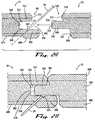
- the tongue connector member and the groove connector membermay also be configured to cooperatively couple with each other such that a distal end 222 of the lower shoulder 220 of the first flooring panel is spaced from the distal end 328 of the lower lip 320 of the second flooring panel upon coupling of the respective tongue and groove connector members of the respective first and second flooring panels to each other along adjacent side edges 100. As illustrated in Fig. 2B , this clearance helps to ensure that the visable joint on the top surface of the adjoining flooring panels is substantially closed, i.e., portions of the distal ends 212, 312 of the respective adjoining upper shoulder and upper lip are placed in an abutting relationship.
- the tongue connector member and the groove connector memberare configured to cooperatively couple with each other such that a portion of the distal peripheral surface of the tongue connector member of the first flooring panel is spaced from a portion of the wall surface 350 of the groove connector member of the second flooring panel upon coupling of the respective tongue and groove connector members of the respective first and second flooring panels to each other along adjacent side edges.
- the spaceprovides additional clearance to enable the joint to completely close in the event that an obstruction, such as a splinter, or an adhesive, becomes trapped between the distal peripheral surface 250 of the tongue connector member 200 and the wall surface of the groove connector member 300.
- an obstructionsuch as a splinter, or an adhesive
- the fastening surfaceis provided on the lower lip of the groove connector member, such that a conventional fastener 20 may engage the flooring member with a portion of the subfloor.
- a conventional fastener 20may engage the flooring member with a portion of the subfloor.
- the placement of the fastener on a portion of the groove connector membermay cause an obstruction when the tongue connector member is attempted to be placed into operative engagement with the groove connector member, which results in the floor panels being placed in an undesirable spaced relationship.
- This issueis addressed in one aspect of the present invention where a portion of the distal peripheral surface 250 of the tongue connector member that adjoins the bottom tongue contact surface 240 is angled with respect to the bottom tongue contact surface.
- the angled portion of the peripheral surfaceoverlies at least a portion of the fastening surface of the lower lip of the groove connector member and thus provides sufficient space so that the tongue connector member 200 can be accepted within the groove connector member 300 without being obstructed by any exposed portion of the fastener 20.
- the fastening surfacedefines a recess 325 spaced from the wall surface 350 of the groove connector member that is configured to receive a fastener.
- the groove connector membermay comprise one recess or a plurality of recesses.
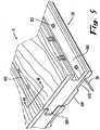
- the recessmay be shaped to engage an individual fastener, such as in Fig. 5 , extends longitudinally substantially parallel to the wall surface of the groove connector member.
- the recess 325extends also longitudinally substantially the length of the flooring panel. It is contemplated that the recess can be spaced along the longitudinal length of the flooring panel. Further, the recess can be spaced from the ends of the flooring panel.
- the fastener 20extends therethrough the lower lip of the groove connector member and exits through the bottom surface 600 of the flooring panel, it has the potential of splintering either the bottom surface of the flooring panel or the top surface of the subfloor, or both.
- the splintersmay cause the flooring panel to lie on the subfloor in an uneven fashion.
- the bottom surface of the flooring paneldefines a trough 610 that at least partially underlies the lower lip of the groove connector member 300.
- the trough 610is configured to provide a relief space for the formed splinters.
- the troughis offset from the fastening surface such that it does not underlie the fastening surface 322.
- the troughextends longitudinally substantially parallel to the groove connector member. In this aspect, the trough may or may not extend substantially the longitudinal dimension of the flooring panel.
- the flooring panel of the present inventionmay comprise a hardwood material, or it may comprise a plurality of materials in a laminate structure.
- the flooring panelcomprises a wood based core material 700 comprising a ground wood product and a binding agent unified to form a cured composite.
- the core material 700may comprise medium density fiberboard ("MDF"), high density fiberboard (“HDF”), or any other conventional wood based product.
- MDFmedium density fiberboard
- HDFhigh density fiberboard
- the respective tongue and groove connector membersare formed from the core material.
- the flooring panelwhen it is a laminate structure, in one aspect, it comprises a decorative layer 800 connected to an upper surface of the core material.
- the decorative layer 800may comprise a melamine sheet, as in conventional laminate structures. It may also comprise a hardwood material, as in engineered hardwood flooring panels. However, it may also comprise any other conventional substance used for decorative layers in laminate flooring boards.
- the flooring panelcomprises a bottom support layer 900 connected to a lower surface of the core material. If the flooring panel comprises a trough 610 defined in its bottom surface, the trough may be defined therein bottom surface of the bottom support layer 900.
- the inventionis also a method for making the flooring panel according to claim 28.
- the methodcomprises the steps of: providing at least one plank of flooring material; forming the aforementioned tongue connector member into and extending along at least one of the side edges of the pair of opposed side edges; and forming the aforementioned groove connector member into and extending along a side edge opposite of the tongue.
- the methodcomprises forming the aforementioned recess in the fastening surface.
- the recessmay comprise a plurality of recesses. Additionally, the method may also comprise forming the trough in the bottom surface of the flooring panel.
Landscapes
- Engineering & Computer Science (AREA)
- Architecture (AREA)
- Civil Engineering (AREA)
- Structural Engineering (AREA)
- Life Sciences & Earth Sciences (AREA)
- Wood Science & Technology (AREA)
- Floor Finish (AREA)
Description
- The present invention pertains to a flooring profile. More specifically, the invention is a flooring profile for use with a hardwood or engineered hardwood flooring board.
- Hardwood flooring has become a very popular choice in floor coverings. Traditional hardwood floors are made from a variety of wood planks and are placed in side-by-side relation to each other with the side edges being engaged with a tongue and groove arrangement. In order to secure the floorboard to the subfloor, nails are driven at an angle through a portion of the tongue of the plank and into the subfloor below.
- One common substitute for hardwood flooring is laminate flooring. Laminate flooring is made to look like hardwood, but is easier to install and less expensive. Laminated flooring members typically comprise a decorative surface layer, a core, a balancing backing layer, and a wear layer, which are bonded together. The decorative surface layer can be made of a resin, such as, for example a melamine/aluminum oxide based resin. The decorative surface layer is typically bonded to a moisture resistant core that can be formed from, for example, a wood composition.
- Conventional cores are made of high or medium density fiberboard that is typically saturated in resins to make them extremely hard. This allows the laminate flooring members to be cut with an edge profile, such as a tongue and complementary groove, as desired, for ease of installation.
- The balancing backing layer is applied to the underside of the core to help stabilize the laminate flooring member and to act as another barrier against moisture entering the laminate flooring member from below. Most manufacturers saturate the backing layer with resin to resist moisture intrusion and to make the balancing backing layer more dimensionally stable. In conventional construction, laminate flooring members formed with a balancing backing layer are not typically glued directly to the sub floor.
- The wear layer is applied to provide protection and stain resistance to protect the top of the laminate flooring member. The wear layer is typically clear so that the aesthetic appearance of the decorative layer, including any color and/or printed image, is not obscured by the overlying wear layer. However, while great care is taken to ensure that the laminate flooring member looks like real hardwood flooring, any damage to the wear layer makes, it evident that it is not true hardwood flooring.
- Another alternative to hardwood flooring is engineered hardwood. An engineered hardwood flooring board is conventionally constructed with an upper layer, a middle layer and a lower layer. The upper layer is typically formed of conventional hardwood flooring material. The middle layer is conventionally formed of a non-hardwood material, such as medium density fiberboard, high density fiberboard, particle board and plywood. The lower layer can also be formed from a hardwood material similar to the upper layer, or it can be formed from a non-hardwood material that has specially selected properties, such as water resistance or rigidity.
- The upper layer of the engineered hardwood flooring board is formed of hardwood to give the board the appearance of conventional hardwood flooring and to enable the engineered hardwood flooring board to be sanded when damaged, similarly to a hardwood-only board.
- Further, the use of alternative material as the middle layer, or core of the board, greatly increases the dimensional stability of the board, which allows the production of engineered hardwood flooring boards that are longer and wider than conventional hardwood flooring boards.
- The material in the middle layer can be formed or milled precisely prior to assembly into the engineered hardwood flooring board, which results in boards with tight tolerances that can easily be engaged with one another to form the flooring surface. In one example, similar to conventional hardwood flooring boards, engineered hardwood flooring boards can comprise a tongue and a complementary groove positioned an and extending along opposite sides of the board. Alternatively, the boards can be secured to one another using a snap-fit profile, similar to those used in the laminate flooring industry.
- Conventional method of installation may cause some installation issues when the engineered hardwood flooring boards are engaged with a traditional tongue and groove connection. Noteably, due to the increased density of the core material used in the middle layer portions of the core may be displaced when a nail or other fastener is driven into the top portion of the tongue, which causes a portion of the surface of the engineered hardwood flooring board to visibly protrude or bubble. In fact, this phenomenon ollen occurs in conventional hardwood flooring boards. What is needed is a flooring board and a method of installing an engineered hardwood flooring board that alleviates the problem of surface bubbling.
DE 20017114U1 discloses a flooring panel according to the preamble of claim 1, and a method for making a panel according to the preamble ofclaim 28. - The present invention pertains to a flooring panel according to claim 1 comprising:
- opposed pairs of substantially parallel side edges;
- a tongue connector member extending along one side edge of at least one of the opposed pairs of side edges, the tongue connector member comprising an upper shoulder and a lower shoulder, wherein the upper shoulder extends distally beyond the lower shoulder; and
- a groove connector member defined in one side edge of at least one of the opposed pairs of side edges, the groove connector member comprising an upper lip and a lower lip, the lower lip extending distally beyond a distal end of the upper lip, wherein the groove connector member comprises an upper groove contact surface, a lower groove contact surface and a wall surface extending between the respective upper and lower groove contact surfaces;
- wherein the tongue connector member is configured to cooperatively couple with the groove connector member such that a distal end of the upper shoulder of a first flooring panel contacts the distal end of the upper lip of a second flooring panel upon coupling of the respective tongue and groove connector members of the respective first and second flooring panels to each other along adjacent side edges; wherein a portion of the lower lip comprises a fastening surface that defines a recess which extends inwardly into the lower lip and which is configured to receive a fastener, that the recess is spaced distally from the wall surface of the groove connector member, that the recess extends longitudinally substantially parallel to the wall surface of the groove connector member, and that the recess does not extend distally beyond the distal end of the upper lip. The present invention pertains to a method for making a flooring panel according to
claim 28, comprising:- providing at least one plank of flooring material, each plank comprising a pair of opposed side edges;
- forming a tongue connector member into and extending along at least one of the side edges of the pair of opposed side edges the tongue connector member comprising an upper shoulder and a lower shoulder, wherein the upper shoulder extends distally beyond the lower shoulder and wherein the tongue connector member comprises a top tongue contact surface, a bottom tongue contact surface, and a distal peripheral surface extending between the respective top and bottom tongue contact surfaces; and forming a groove connector member into and extending along a side edge opposite of the tongue, the groove connector member comprising an upper lip and a lower lip, the lower lip extending distally beyond a distal end of the upper lip, wherein the groove connector member defines a groove comprising an upper groove contact surface, a lower groove contact surface, and a wall surface extending between the respective upper and lower groove contact surfaces, and wherein the tongue connector member and the groove connector member are configured to cooperatively couple with each other such that a distal end of the upper shoulder of a first flooring panel contacts a distal end of the upper lip of a second flooring panel upon coupling of the respective tongue and groove connector members of the respective first and second flooring panels to each other along adjacent side edges, wherein at least a portion of the lower groove contact surface comprises a fastening surface that defined at least one recess which extends inwardly into the lower lip and which is configured to receive a fastener, that the recess is spaced distally from the wall surface of the groove connector member, that the recess extends longitudinally substantially parallel to the wall surface of the groove connector member, and that the recess does not extend distally beyond the distal end of the upper lip.
- Other aspects and advantages of the invention will be discussed with reference to the Figures and to the detailed description of the preferred embodiments
- The accompanying drawings, which are incorporated in and constitute a part of this specification, illustrate several aspects described below and together with the description, serve to explain the principles of the invention. Like numbers represent the same elements throughout the figures.
Fig. 1 is a perspective view of one aspect of the present invention for a flooring panel showing adjacent first and second flooring panels coupled with each other and showing a fastened engaged therethrough a longitudinally extending recess defined in a fastening surface of a lower lip of a groove connector member.Fig. 2A is a partial end elevational view of the adjacent flooring panels ofFig.1 in an uncoupled position.Fig. 2B is a partial cross-sectional view of the adjacent flooring panels ofFig.1 , taken acrossline 2B-2B ofFig.1 .Fig. 3 is a perspective view of one aspect which is not part of the present invention for a flooring panel showing adjacent first and a second flooring panels coupled with each other and showing a fastener engaged therethrough a fastening surface of a lower lip of a groove connector member and extending out of a portion of trough defined in a bottom surface of the flooring panel.Fig. 4A is a partial end elevational view of the adjacent flooring panels ofFig.3 in an uncoupled position.Fig. 4B is a is partial cross-sectional view of the adjacent flooring panels ofFig. 3 , taken acrossline 4B-4B ofFig. 3 , showing a distal peripheral surface of the tongue connector member which is angled with respect to a bottom tongue contact surface.Fig. 5 is a perspective view of one aspect of the present invention for a flooring panel showing adjacent first and second flooring panels coupled with each other and showing a plurality of recesses defined in a fastening surface of a lower lip of a groove connector member.Fig. 6A is a partial end elevational view of the adjacent flooring panels ofFig. 5 in an uncoupled position.Fig. 6B is a partial cross-sectional view of the adjacent flooring panels ofFig.5 , taken across line 6B-6B ofFig. 5 .- The present invention can be understood more readily by reference to the following detailed description, examples, drawings, and claims, and their previous and following description. However, before the present devices, systems, and/or methods are disclosed and described, it is to be understood that this invention is not limited to the specific devices, systems, and/or methods disclosed unless otherwise specified, as such can, of course, vary. It is also to be understood that the terminology used herein is for the purpose of describing particular aspects only and is not intended to be limiting. The present invention can be understood more readily by reference to the following detailed description, examples, drawings, and claims, and their previous and following description. However, before the present devices, systems, and/or methods are disclosed and described, it is to be understood that this invention is not limited to the specific devices, systems, and/or methods disclosed unless otherwise specified, as such can, of course, vary. It is also to be understood that the terminology used herein is for the purpose of describing particular aspects only and is not intended to be limiting.
- The following description of the invention is provided as an enabling teaching of the invention in its best, currently known embodiment. To this end, those skilled in the relevant art will recognize and appreciate that many changes can be made to the various aspects of the invention described herein, while still obtaining the beneficial results of the present invention. It will also be apparent that some of the desired benefits of the present invention can be obtained by selecting some of the features of the present invention without utilizing other features. Accordingly, those who work in the art will recognize that many modifications and adaptations to the present invention are possible and can even be desirable in certain circumstances and are a part of the present invention. Thus, the following description is provided as illustrative of the principles of the present invention and not in limitation thereof.
- As used herein, the singular forms "a," "an" and "the" include plural referents unless the context clearly dictates otherwise. Thus, for example, reference to a "flooring panel" includes aspects having two or more such flooring panels unless the context clearly indicates otherwise.
- Ranges can be expressed herein as from "about" one particular value, and/or to "about" another particular value. When such a range is expressed, another aspect includes from the one particular value and/or to the other particular value. Similarly, when values are expressed as approximations, by use of the antecedent "about," it will be understood that the particular value forms another aspect. It will be further understood that the endpoints of each of the ranges are significant both in relation to the other endpoint, and independently of the other endpoint.
- As used herein, the terms "optional" or "optionally" mean that the subsequently described event or circumstance may or may not occur, and that the description includes instances where said event or circumstance occurs and instances where it does not.
- The present invention may be understood more readily by reference to the following detailed description of preferred embodiments of the invention and the examples included therein and to the Figures and their previous and following description.
- In one aspect, the present invention is a
flooring panel 10 that comprises opposed pairs of substantially parallel side edges 100. In one aspect, the flooring panel comprises a tongue and groove edge profile. In this aspect, there is atongue connector member 200 extending along one side edge of at least one of the opposed pairs of side edges 100. Thetongue connector member 200 itself comprises anupper shoulder 210 that extends distally beyond alower shoulder 220. In yet another aspect, the tongue connector member has a toptongue contact surface 230, a bottomtongue contact surface 240 and a distalperipheral surface 250 that extends between the respective top and bottom tongue contact surfaces. - A
groove connector member 300 is defined in one side edge of at least one of the opposed pairs of side edges. As illustrated inFig. 1 , thegroove connector member 300 comprises anupper lip 310 and alower lip 320. In one aspect, thelower lip 320 extends distally beyond theupper lip 310. The tongue connector member and the groove connector member are configured to cooperatively couple with each other. The lower lip has afastening surface 322, which is configured to accept a variety of conventional fasteners, such as, for example and not meant to be limiting, one or more nails, staples, tacks, and the like. - As one skilled in the art can appreciate, the flooring panels may be engaged with the subfloor by an adhesive, such as glue. In this aspect, the adhesive is placed on the top surface of the subfloor or the
bottom surface 600 of the flooring panel. Since the lower lip of the groove connector member extends distally beyond the upper lip, during installation, the tongue connector member from anadjacent flooring panel 10 may be placed onto the lower lip of the groove connector member that is adhesively secured to the subfloor (at an angle with respect to the subfloor) and slid substantially into engagement prior to the bottom surface of the adjacent flooring panel coming into contact with the adhesive. - The
groove connector member 300 has an uppergroove contact surface 330, a lowergroove contact surface 340 and awall surface 350 that extends between the respective top and bottom groove contact surfaces. In one exemplary aspect, at least a portion of the lowergroove contact surface 340 is thefastening surface 322. - The
tongue connector member 200 and thegroove connector member 300 are configured to cooperatively couple with each other such that adistal end 212 of theupper shoulder 210 of a first flooring panel contacts adistal end 312 of theupper lip 310 of a second flooring panel upon coupling of the respective tongue and groove connector members of the respective first and second flooring panels to each other along adjacent side edges. In this fashion, the adjacent flooring panels have the perception of being joined when looking at the flooring system. As one skilled in the art can appreciate and as illustrated in the figures, thedistal end 312 of the upper lip of the second flooring panel and thedistal end 212 of the upper shoulder of the first flooring panel may be beveled such that, when the adjacent flooring panels are coupled, the seam between the two flooring panels forms a recessedchannel 400. A benefit of this feature is to disguise imperfections in the flooring panels to the extent that the uppermost surfaces of the adjacent panels may not be perfectly coplanar. - The tongue connector member and the groove connector member may also be configured to cooperatively couple with each other such that a
distal end 222 of thelower shoulder 220 of the first flooring panel is spaced from thedistal end 328 of thelower lip 320 of the second flooring panel upon coupling of the respective tongue and groove connector members of the respective first and second flooring panels to each other along adjacent side edges 100. As illustrated inFig. 2B , this clearance helps to ensure that the visable joint on the top surface of the adjoining flooring panels is substantially closed,i.e., portions of the distal ends 212, 312 of the respective adjoining upper shoulder and upper lip are placed in an abutting relationship. - In a further aspect, the tongue connector member and the groove connector member are configured to cooperatively couple with each other such that a portion of the distal peripheral surface of the tongue connector member of the first flooring panel is spaced from a portion of the
wall surface 350 of the groove connector member of the second flooring panel upon coupling of the respective tongue and groove connector members of the respective first and second flooring panels to each other along adjacent side edges. The space provides additional clearance to enable the joint to completely close in the event that an obstruction, such as a splinter, or an adhesive, becomes trapped between the distalperipheral surface 250 of thetongue connector member 200 and the wall surface of thegroove connector member 300. Further, in one aspect, in a coupled position, the distal peripheral surface of the tongue connector member of the first flooring panel, the wall surface of the groove connector member and portions of the respective upper and lower groove contact surfaces define alongitudinally extending pocket 500. - As mentioned herein above, the fastening surface is provided on the lower lip of the groove connector member, such that a
conventional fastener 20 may engage the flooring member with a portion of the subfloor. In conventional flooring profiles the placement of the fastener on a portion of the groove connector member may cause an obstruction when the tongue connector member is attempted to be placed into operative engagement with the groove connector member, which results in the floor panels being placed in an undesirable spaced relationship. This issue is addressed in one aspect of the present invention where a portion of the distalperipheral surface 250 of the tongue connector member that adjoins the bottomtongue contact surface 240 is angled with respect to the bottom tongue contact surface. One will appreciate that, in an adjoined position, the angled portion of the peripheral surface overlies at least a portion of the fastening surface of the lower lip of the groove connector member and thus provides sufficient space so that thetongue connector member 200 can be accepted within thegroove connector member 300 without being obstructed by any exposed portion of thefastener 20. - The fastening surface defines a
recess 325 spaced from thewall surface 350 of the groove connector member that is configured to receive a fastener. The groove connector member may comprise one recess or a plurality of recesses. The recess may be shaped to engage an individual fastener, such as inFig. 5 , extends longitudinally substantially parallel to the wall surface of the groove connector member. In yet another aspect, such as inFig. 1 , therecess 325 extends also longitudinally substantially the length of the flooring panel. It is contemplated that the recess can be spaced along the longitudinal length of the flooring panel. Further, the recess can be spaced from the ends of the flooring panel. - In some instances, as the
fastener 20 extends therethrough the lower lip of the groove connector member and exits through thebottom surface 600 of the flooring panel, it has the potential of splintering either the bottom surface of the flooring panel or the top surface of the subfloor, or both. The splinters may cause the flooring panel to lie on the subfloor in an uneven fashion. To counter this problem, in one aspect, the bottom surface of the flooring panel defines atrough 610 that at least partially underlies the lower lip of thegroove connector member 300. Thetrough 610 is configured to provide a relief space for the formed splinters. In another aspect, the trough is offset from the fastening surface such that it does not underlie thefastening surface 322. In yet another aspect, the trough extends longitudinally substantially parallel to the groove connector member. In this aspect, the trough may or may not extend substantially the longitudinal dimension of the flooring panel. - As one skilled in the art can appreciate, the flooring panel of the present invention may comprise a hardwood material, or it may comprise a plurality of materials in a laminate structure. In one aspect, the flooring panel comprises a wood based
core material 700 comprising a ground wood product and a binding agent unified to form a cured composite. As such, thecore material 700 may comprise medium density fiberboard ("MDF"), high density fiberboard ("HDF"), or any other conventional wood based product. In yet another aspect, the respective tongue and groove connector members are formed from the core material. - When the flooring panel is a laminate structure, in one aspect, it comprises a
decorative layer 800 connected to an upper surface of the core material. Thedecorative layer 800 may comprise a melamine sheet, as in conventional laminate structures. It may also comprise a hardwood material, as in engineered hardwood flooring panels. However, it may also comprise any other conventional substance used for decorative layers in laminate flooring boards. - In another aspect, the flooring panel comprises a
bottom support layer 900 connected to a lower surface of the core material. If the flooring panel comprises atrough 610 defined in its bottom surface, the trough may be defined therein bottom surface of thebottom support layer 900. - The invention is also a method for making the flooring panel according to
claim 28. The method comprises the steps of: providing at least one plank of flooring material; forming the aforementioned tongue connector member into and extending along at least one of the side edges of the pair of opposed side edges; and forming the aforementioned groove connector member into and extending along a side edge opposite of the tongue. - The method comprises forming the aforementioned recess in the fastening surface. As mentioned herein above, the recess may comprise a plurality of recesses. Additionally, the method may also comprise forming the trough in the bottom surface of the flooring panel.
Claims (42)
- A flooring panel (10), comprising:opposed pairs of substantially parallel side edges (100, 100);a tongue connector member (200) extending along one side edge of at least one of the opposed pairs of side edges (100, 100), the tongue connector member comprising an upper shoulder (210) and a lower shoulder (220), wherein the upper shoulder (210) extends distally beyond the lower shoulder (220); anda groove connector member (300) defined in one side edge of at least one of the opposed pairs of side edges (100, 100), the groove connector member (300) comprising an upper lip (310) and a lower lip (320), the lower lip (320) extending distally beyond a distal end (312) of the upper lip (310), wherein the groove connector member (300) comprises an upper groove contact surface (330), a lower groove contact surface (340) and a wall surface (350) extending between the respective upper and lower groove contact surfaces (330, 340);wherein the tongue connector member (200) is configured to cooperatively couple with the groove connector member (300) such that a distal end (212) of the upper shoulder (210) of a first flooring panel (10) contacts the distal end (312) of the upper lip (310) of a second flooring panel (10) upon coupling of the respective tongue and groove connector members (200, 300) of the respective first and second flooring panels (10, 10) to each other along adjacent side edges (100, 100);wherein a portion of the lower groove contact surface (340) comprises a fastening surface (322) that defines a recess (325) which extends inwardly into the lower lip (320) and which is configured to receive a fastener (20), that the recess (325) is spaced distally from the wall surface of the groove connector member (300), that the recess (325) extends longitudinally substantially parallel to the wall surface of the groove connector member (300),characterized in that the recess (325) does not extend distally beyond the distal end (312) of the upper lip (320).
- The flooring panel (10) of Claim 1, wherein the tongue connector member (200) and the groove connector member (300) are configured to cooperatively couple with each other, such that a distal end (212) of the lower shoulder (220) of the first flooring panel (10) is spaced from a distal end portion (328) of the lower lip (320) of the second flooring panel (10) upon coupling of the respective tongue and groove connector members (200, 300) of the respective first and second flooring panels (10, 10) to each other along adjacent side edges (100, 100).
- The flooring panel (10) of Claim 1, wherein the tongue connector member (200) has a top tongue contact surface (230), a bottom tongue contact surface (240) and a distal peripheral surface (250) extending between the respective top and bottom tongue contact surfaces (230, 240).
- The flooring panel (10) of Claim 3, wherein the groove connector member (300) has an upper groove contact surface (330), a lower groove contact surface (340) and a wall surface (350) extending between the respective upper and lower groove contact surfaces (330, 340), and wherein at least a portion of the lower groove contact surface (340) is the fastening surface (322).
- The flooring panel (10) of Claim 4, wherein the tongue connector member (200) and the groove connector member (300) are configured to cooperatively couple with each other such that a portion of the distal peripheral surface (250) of the tongue connector member (200) of a first flooring panel (10) is spaced from a portion of the wall surface (350) of the groove connector member (300) of a second flooring panel (10) upon coupling of the respective tongue and groove connector members (200, 300) of the respective first and second flooring panels (10, 10) to each other along adjacent side edges (100, 100).
- The flooring panel (10) of Claim 4, wherein, in a coupled position, the distal peripheral surface (250) of the tongue connector member (200) of a first flooring panel (10), the wall surface (350) of the groove connector member (300) and portions of the respective upper and lower groove contact surfaces (330, 340) define a longitudinally extending pocket (500).
- The flooring panel (10) of Claim 4, wherein a portion of the distal peripheral surface (250) of the tongue connector member (200) that adjoins the bottom tongue contact surface (240) is angled with respect to the bottom tongue contact surface (240).
- The flooring panel (10) of Claim 1, wherein the flooring panel (10) has a bottom surface (600), and wherein the bottom surface (600) defines a trough (610) that at least partially underlies the lower lip (320) of the groove connector member (300).
- The flooring panel (10) of Claim 8, wherein the trough (600) is offset from the fastening surface (322) such that it does not underlie the fastening surface (322).
- The flooring panel (10) of Claim 8, wherein the trough (610) extends longitudinally substantially parallel to the groove connector member (300).
- The flooring panel (10) of Claim 8, wherein the trough (610) extends substantially the longitudinal dimension of the flooring panel (10).
- The flooring panel (10) of Claim 1, wherein the recess (325) comprises a plurality of recesses (325).
- The flooring panel (10) of Claim 1, wherein the flooring panel (10) has a longitudinal length, and wherein the recess (325) extends longitudinally substantially parallel to the wall surface of the groove connector member (300) substantially the longitudinal length of the flooring panel (10).
- The flooring panel (10) of Claim 1, wherein the flooring panel (10) comprises a wood based core material (700) comprising a ground wood product and a binding agent unified to form a cured composite.
- The flooring panel (10) of Claim 14, wherein the core material (700) comprises MDF.
- The flooring panel (10) of Claim 14, wherein the core material (700) comprises HDF.
- The flooring panel (10) of Claim 14, wherein the flooring panel (10) comprises a decorative layer (800) connected to an upper surface of the core material (700).
- The flooring panel (10) of Claim 17, wherein the decorative layer (800) is formed from a hardwood.
- The flooring panel (10) of Claim 14, wherein the flooring panel (10) comprises a bottom support layer (900) connected to a lower surface of the core material (700).
- The flooring panel (10) of Claim 19, wherein the bottom support layer (900) has a bottom surface (600), and wherein the bottom surface defines a trough (610) that at least partially underlies the lower lip (320) of the groove connector member (300).
- The flooring panel (10) of Claim 20, wherein the trough (610) is offset from the fastening surface (322) such that it does not underlie the fastening surface (322).
- The flooring panel (10) of Claim 20, wherein the trough (610) extends longitudinally substantially parallel to the groove connector member (300).
- The flooring panel (10) of Claim 20, wherein the trough (610) extends substantially the longitudinal dimension of the flooring panel (10).
- The flooring panel (10) of Claim 19, wherein the bottom support layer (900) is formed from a hardwood.
- The flooring panel (10) of Claim 14, wherein the respective tongue and groove connector members (200, 300) are made from the core material.
- The flooring panel (10) of claim 1, comprising:a bottom surface (600);opposed pairs of substantially parallel side edges (100, 100);a tongue connector member (200) anda groove connector member (300) as defined in claim 1;wherein the tongue connector member (200) and the groove connector member (300) are configured to cooperatively couple with each other such that a distal end (212) of the upper shoulder (210) of a first flooring panel (10) contacts a distal end (312) of the upper lip (310) of a second flooring panel (10) upon coupling of the respective tongue and groove connector members (200, 300) of the respective first and second flooring panels (10, 10) to each other along adjacent side edges (100, 100), and wherein the bottom surface (600) of the flooring panel (10) defines a trough (610) that at least partially underlies the lower lip (320) of the groove connector member (300).
- The flooring panel (10) of Claim 26, wherein the trough (610) is offset from the fastening surface (322) such that the trough (610) does not underlie the fastening surface (322).
- A method for making a flooring panel (10), comprising:providing at least one plank of flooring material, each plank comprising a pair of opposed side edges (100, 100);forming a tongue connector member (200) into and extending along at least one of the side edges of the pair of opposed side edges (100, 100), the tongue connector member (200) comprising an upper shoulder (210) and a lower shoulder (220), wherein the upper shoulder (210) extends distally beyond the lower shoulder (220) and wherein the tongue connector member (200) comprises a top tongue contact surface (230), a bottom tongue contact surface (240), and a distal peripheral surface (250) extending between the respective top and bottom tongue contact surfaces (230, 240); andforming a groove connector member (300) into and extending along a side edge (100) opposite of the tongue (200), the groove connector member (300) comprising an upper lip (310) and a lower lip (320), the lower lip (320) extending distally beyond a distal end (312) of the upper lip (310), wherein the groove connector member (300) defines a groove comprising an upper groove contact surface (330), a lower groove contact surface (340), and a wall surface (350) extending between the respective upper and lower groove contact surfaces (330, 340), and wherein the tongue connector member (200) and the groove connector member (300) are configured to cooperatively couple with each other such that a distal end (312) of the upper shoulder (210) of a first flooring panel (10) contacts a distal end (312) of the upper lip (310) of a second flooring panel (10) upon coupling of the respective tongue and groove connector members (200, 300) of the respective first and second flooring panels (10, 10) to each other along adjacent side edges (100, 100),wherein at least a portion of the lower groove contact surface (340) comprises a fastening surface (322) that defined at least one recess (325) which extends inwardly into the lower lip (320) and which is configured to receive a fastener (20), that the recess (325) is spaced distally from the wall surface (350) of the groove connector member (300), that the recess (325) extends longitudinally substantially parallel to the wall surface (350) of the groove connector member (300),characterized in that the recess (325) does not extend distally beyond the distal end (312) of the upper lip (310).
- The method of Claim 28, wherein a portion of the distal peripheral surface (250) of the tongue connector member (200) that adjoins the bottom tongue contact surface (240) is angled with respect to the bottom tongue contact surface (240).
- The method of Claim 28, wherein the at least one recess (325) comprises a plurality of recesses (325).
- The method of Claim 28, wherein the plank comprises a core material (700) comprising a ground wood product and a binding agent.
- The method of Claim 31, wherein the core material (700) comprises MDF.
- The method of Claim 31, wherein the core material (700) comprises HDF.
- The method of Claim 31, wherein the plank comprises a decorative layer (800) connected to an upper surface of the core material (700).
- The method of Claim 34, wherein the decorative layer (800) is formed from a hardwood.
- The method of Claim 31, wherein the plank comprises a bottom support layer (900) connected to a lower surface of the core material (700).
- The method of Claim 36, further comprising forming a trough (610) in the bottom support layer (900) that at least partially underlies the lower lip (320) of the groove connector member (300).
- The method of Claim 37, wherein the trough (610) is offset from the fastening surface (322) such that it does not underlie the fastening surface (322).
- The method of Claim 37, wherein the trough (610) extends longitudinally substantially parallel to the groove connector member (300).
- The method of Claim 37, wherein the trough (610) extends substantially the longitudinal dimension of the flooring panel (10).
- The method of Claim 36, wherein the bottom support layer (900) is formed from a hardwood.
- The method of Claim 31, wherein the respective tongue and groove connector members (200, 300) are formed from the core material (700).
Priority Applications (1)
| Application Number | Priority Date | Filing Date | Title |
|---|---|---|---|
| PL07774548TPL2004922T3 (en) | 2006-03-31 | 2007-03-30 | Flooring profile |
Applications Claiming Priority (2)
| Application Number | Priority Date | Filing Date | Title |
|---|---|---|---|
| US11/395,035US7926239B2 (en) | 2006-03-31 | 2006-03-31 | Flooring profile |
| PCT/US2007/008245WO2007117422A2 (en) | 2006-03-31 | 2007-03-30 | Flooring profile |
Publications (3)
| Publication Number | Publication Date |
|---|---|
| EP2004922A2 EP2004922A2 (en) | 2008-12-24 |
| EP2004922A4 EP2004922A4 (en) | 2012-05-09 |
| EP2004922B1true EP2004922B1 (en) | 2017-04-26 |
Family
ID=38581567
Family Applications (1)
| Application Number | Title | Priority Date | Filing Date |
|---|---|---|---|
| EP07774548.7AActiveEP2004922B1 (en) | 2006-03-31 | 2007-03-30 | Flooring profile |
Country Status (7)
| Country | Link |
|---|---|
| US (1) | US7926239B2 (en) |
| EP (1) | EP2004922B1 (en) |
| KR (1) | KR101399050B1 (en) |
| CN (1) | CN101454518B (en) |
| MX (1) | MX2008013792A (en) |
| PL (1) | PL2004922T3 (en) |
| WO (1) | WO2007117422A2 (en) |
Families Citing this family (24)
| Publication number | Priority date | Publication date | Assignee | Title |
|---|---|---|---|---|
| EP2066854B1 (en) | 2006-09-11 | 2017-04-12 | Spanolux N.V.- DIV. Balterio | Apparatus and method of making a covering panel with bevelled edges having varying cross-section |
| CH703686B1 (en)* | 2007-01-16 | 2012-03-15 | Pierre-Louis Zuber | Assembly of wood blades. |
| CA2623707A1 (en)* | 2008-03-07 | 2009-09-07 | Pierre Trudel | Tongue and groove profile to ease desassembly of floorboards |
| US8166718B2 (en)* | 2008-10-10 | 2012-05-01 | Liu David C | Horizontally engineered hardwood floor and method of installation |
| USD656245S1 (en)* | 2009-04-16 | 2012-03-20 | Rene St-Cyr (1996) Inc. | Floor plank |
| KR200448340Y1 (en)* | 2009-09-04 | 2010-04-05 | 주식회사 승보 | Synthetic Wood Deck Structure |
| AT510089B1 (en)* | 2010-07-13 | 2012-09-15 | Tuechler Buehnen & Textiltechnik Gmbh | FLOORING |
| US9394698B2 (en) | 2012-02-23 | 2016-07-19 | Admiral Composite Technologies, Inc. | Deck system and components |
| US10760283B2 (en) | 2012-02-23 | 2020-09-01 | Admiral Composite Technologies, Inc. | Deck system and components |
| US9353533B2 (en)* | 2012-02-23 | 2016-05-31 | Admiral Composite Technologies, Inc. | Deck system components |
| CA145767S (en) | 2012-05-25 | 2013-01-04 | Polymos Inc | FLOORING PANEL |
| CN104582916A (en)* | 2012-06-19 | 2015-04-29 | 瓦林格创新股份有限公司 | Method for dividing a panel into a first panel and a second panel, method of forming a mechanical locking system for locking the first and second panels, and building panels |
| US9453346B2 (en)* | 2013-09-16 | 2016-09-27 | Best Woods Inc. | Surface covering connection joints |
| WO2015130169A1 (en) | 2014-02-26 | 2015-09-03 | Innovations 4 Flooring Holding N.V. | Panel interconnectable with similar panels for forming a covering |
| US9487958B2 (en) | 2014-09-02 | 2016-11-08 | Boa-Franc S.E.N.C. | Composite engineered wood material piece composed of an HDF mid-layer and an OSB bottom layer |
| MX2018005114A (en)* | 2015-10-28 | 2018-06-06 | Armstrong World Ind Inc | Improved fire performance for wood veneer laminated ceiling tile. |
| US20180127990A1 (en)* | 2016-11-09 | 2018-05-10 | Marcin Mieczkowski | Subfloor Leveling Assembly |
| CA3061003A1 (en)* | 2017-04-18 | 2018-10-25 | Louisiana-Pacific Corporation | Self-spacing lap siding product |
| US11156002B2 (en)* | 2017-04-18 | 2021-10-26 | Louisiana-Pacific Corporation | Self-spacing lap siding product |
| US11225799B2 (en)* | 2017-04-18 | 2022-01-18 | Louisiana-Pacific Corporation | Self-spacing lap siding product |
| US12084869B2 (en)* | 2017-04-18 | 2024-09-10 | Louisiana-Pacific Corp. | Self-spacing lap siding product |
| US10563412B1 (en)* | 2018-11-30 | 2020-02-18 | Cary Paik | Acoustic flooring assembly |
| US20210246656A1 (en)* | 2020-02-06 | 2021-08-12 | Louisiana-Pacific Corporation | Self-spacing lap and panel siding |
| US11479015B2 (en)* | 2020-02-14 | 2022-10-25 | Divergent Technologies, Inc. | Custom formed panels for transport structures and methods for assembling same |
Family Cites Families (92)
| Publication number | Priority date | Publication date | Assignee | Title |
|---|---|---|---|---|
| US174261A (en)* | 1876-02-29 | Improvement in flooring | ||
| US337564A (en)* | 1886-03-09 | Signoe to himself and john j | ||
| US316175A (en) | 1885-04-21 | Alfred putney | ||
| US890436A (en)* | 1907-10-11 | 1908-06-09 | Christian Momberg | Matched flooring. |
| US1124228A (en)* | 1913-02-28 | 1915-01-05 | Ross Houston | Matched flooring or board. |
| US1430996A (en) | 1921-12-10 | 1922-10-03 | Horlin Mauritz Isidor | Method of manufacturing wainscots |
| US1472521A (en) | 1922-08-26 | 1923-10-30 | Miller Rubber Co | Building element |
| US1778069A (en) | 1928-03-07 | 1930-10-14 | Bruce E L Co | Wood-block flooring |
| US1778068A (en) | 1928-03-07 | 1930-10-14 | Cellized Oak Flooring Inc | Wood-block flooring |
| US1778352A (en) | 1928-04-14 | 1930-10-14 | Cellized Oak Flooring Inc | Wood flooring |
| US1764331A (en)* | 1929-02-23 | 1930-06-17 | Paul O Moratz | Matched hardwood flooring |
| US1859667A (en)* | 1930-05-14 | 1932-05-24 | J K Gruner Lumber Company | Jointed lumber |
| US1832397A (en) | 1930-10-20 | 1931-11-17 | Victor J Hultquist | Tile |
| US2045068A (en) | 1930-12-08 | 1936-06-23 | Bruce E L Co | Wood block |
| US1936028A (en) | 1931-08-27 | 1933-11-21 | Byrd C Rockwell | Flooring construction |
| US2004917A (en) | 1932-05-04 | 1935-06-11 | Lug Lox Flooring Company | Means for attaching floor boards |
| US1925068A (en) | 1932-07-11 | 1933-08-29 | Bruce E L Co | Floor |
| US1986739A (en) | 1934-02-06 | 1935-01-01 | Walter F Mitte | Nail-on brick |
| US2017185A (en) | 1934-08-21 | 1935-10-15 | Byrd C Rockwell | Sliver pocket flooring |
| US2031596A (en) | 1935-02-19 | 1936-02-25 | Clarence C Fulbright | Floor block |
| US2092694A (en) | 1935-03-02 | 1937-09-07 | Kenneth E Crooks | Composite flooring and method of laying the same |
| US2114451A (en) | 1936-11-02 | 1938-04-19 | Lee H Mattes | Building covering construction |
| US2152694A (en) | 1938-03-28 | 1939-04-04 | Otto P Tiemann | Hardwood flooring |
| US2227878A (en) | 1938-04-14 | 1941-01-07 | Kenneth E Crooks | Flooring |
| US2269926A (en) | 1939-01-06 | 1942-01-13 | Kenneth E Crooks | Composite board flooring |
| US2269927A (en) | 1939-07-27 | 1942-01-13 | Kenneth E Crooks | Composite floor and floor unit for forming the same |
| US2226540A (en) | 1940-07-16 | 1940-12-31 | William A F Boettcher | Floor block |
| US2328051A (en) | 1940-08-21 | 1943-08-31 | Minnesota & Ontario Paper Co | Wall construction |
| US2817125A (en) | 1955-10-25 | 1957-12-24 | Bennie C Johns | Interlocking fasteners for building materials |
| US2874603A (en) | 1956-05-25 | 1959-02-24 | William A Boettcher | Nail with frangible extension |
| US3200553A (en) | 1963-09-06 | 1965-08-17 | Forrest Ind Inc | Composition board flooring strip |
| US3551270A (en) | 1967-01-30 | 1970-12-29 | Melvin Sharkey | Bonding air-impervious flexible sheets using an adhesive,perforated,inner sheet and article produced thereby |
| US3579941A (en) | 1968-11-19 | 1971-05-25 | Howard C Tibbals | Wood parquet block flooring unit |
| US3567563A (en) | 1968-12-26 | 1971-03-02 | Goodyear Aerospace Corp | Lightweight,high strength core material in a structural panel |
| SE0001325L (en) | 2000-04-10 | 2001-06-25 | Valinge Aluminium Ab | Locking systems for joining floorboards and floorboards provided with such locking systems and floors formed from such floorboards |
| US3619963A (en) | 1969-07-31 | 1971-11-16 | Powerlock Floors Inc | Flooring system |
| US3577694A (en) | 1969-08-18 | 1971-05-04 | Powerlock Floors Inc | Flooring systems |
| US3596422A (en) | 1970-03-16 | 1971-08-03 | William A Boettcher | Securing means for flooring |
| US3740910A (en) | 1971-11-01 | 1973-06-26 | Merry Co Inc | Simulated brick panels |
| AT341738B (en)* | 1974-12-24 | 1978-02-27 | Hoesch Werke Ag | CONNECTING ELEMENT WITH SLOT AND SPRING CONNECTION |
| US4489512A (en) | 1980-10-03 | 1984-12-25 | Schovee John R | Article for forming a picture frame |
| US4599842A (en) | 1984-08-20 | 1986-07-15 | James Counihan | Planar section fastening system |
| US4856250A (en) | 1987-04-17 | 1989-08-15 | Gronau Arthur W | Sleeper for the attachment of covering material to a surface |
| US4782989A (en) | 1987-08-17 | 1988-11-08 | Viking Engineering & Development, Inc. | Compensating nail-driving chuck for pallet-making machine |
| US4831806A (en) | 1988-02-29 | 1989-05-23 | Robbins, Inc. | Free floating floor system |
| US4890434A (en) | 1989-02-08 | 1990-01-02 | Robbins, Inc. | Hardwood floor system |
| US5016413A (en) | 1990-02-14 | 1991-05-21 | James Counihan | Resilient floor system |
| US5088260A (en) | 1990-07-23 | 1992-02-18 | Barton James J | System and method for joining structural panels |
| USRE37615E1 (en) | 1992-07-13 | 2002-04-02 | Robbins, Inc. | Anchored/resilient hardwood floor system |
| US5609000A (en) | 1992-07-13 | 1997-03-11 | Robbins, Inc. | Anchored/resilient hardwood floor system |
| US5312022A (en) | 1992-09-24 | 1994-05-17 | Viking Engineering & Development, Incorporated | Compensating nail-driving chuck for pallet-making machine |
| SE501014C2 (en) | 1993-05-10 | 1994-10-17 | Tony Pervan | Grout for thin liquid hard floors |
| US5500980A (en)* | 1993-11-16 | 1996-03-26 | Morrow Associated Enterprises | Carpet strips and methods of making carpet strips and other extruded articles |
| JP3134142B2 (en)* | 1993-12-28 | 2001-02-13 | 朝日ウッドテック株式会社 | Flooring and floor structure |
| US5465548A (en) | 1994-03-16 | 1995-11-14 | Robbins, Inc. | Prefabricated sleeper for anchored and resilient hardwood floor system |
| US5570554A (en)* | 1994-05-16 | 1996-11-05 | Fas Industries, Inc. | Interlocking stapled flooring |
| US6610228B2 (en) | 1996-03-21 | 2003-08-26 | Santee, Inc. | Dry process for bonding silica-rich plant materials |
| JP3002866B2 (en)* | 1996-10-07 | 2000-01-24 | 株式会社住建産業 | Floor material |
| JPH10205042A (en)* | 1997-01-22 | 1998-08-04 | S S Japan:Kk | Method for preventing floor creaking |
| US5894700A (en) | 1997-08-04 | 1999-04-20 | Triangle Pacific Corporation | Glue-down prefinished wood flooring product |
| US5879781A (en) | 1997-08-20 | 1999-03-09 | The Mead Corporation | Flooring laminate having noise reduction properties |
| SE513151C2 (en) | 1998-02-04 | 2000-07-17 | Perstorp Flooring Ab | Guide heel at the joint including groove and spring |
| US6182413B1 (en) | 1999-07-27 | 2001-02-06 | Award Hardwood Floors, L.L.P. | Engineered hardwood flooring system having acoustic attenuation characteristics |
| US6367217B1 (en) | 1999-11-04 | 2002-04-09 | Robbins, Inc. | Sleeper assembly for resilient hardwood floor system |
| JP2001248289A (en)* | 2000-03-06 | 2001-09-14 | Eidai Co Ltd | Board material |
| GB0008593D0 (en)* | 2000-04-08 | 2000-05-31 | Crout Brian R | Timber decking |
| AT411374B (en) | 2000-06-06 | 2003-12-29 | Kaindl M | COATING, COVERING OR THE LIKE, PANELS FOR ITS EDUCATION AND METHOD AND DEVICE FOR PRODUCING THE PANELS |
| BE1013569A3 (en) | 2000-06-20 | 2002-04-02 | Unilin Beheer Bv | Floor covering. |
| DE20017114U1 (en)* | 2000-10-04 | 2000-12-21 | Dammers, Dirk, 47506 Neukirchen-Vluyn | Panel element |
| US6851241B2 (en) | 2001-01-12 | 2005-02-08 | Valinge Aluminium Ab | Floorboards and methods for production and installation thereof |
| US20020100231A1 (en) | 2001-01-26 | 2002-08-01 | Miller Robert J. | Textured laminate flooring |
| DK200101766A (en) | 2001-03-21 | 2002-09-22 | Faxe Design As | Cover for a parquet floor |
| US6484466B2 (en) | 2001-04-04 | 2002-11-26 | Wu Yi Chun | Hardwood floor system including a piece of sponge, e-shaped plastic racks with ribs whose projections engage the shoulders and inclined surfaces of a plurality of floor boards |
| US20030121226A1 (en) | 2001-07-25 | 2003-07-03 | Manuel Bolduc | Method for installing wood flooring |
| US20050005558A1 (en) | 2001-07-25 | 2005-01-13 | Manuel Bolduc | Method for installing wood flooring |
| EP1485550B1 (en) | 2001-12-06 | 2009-05-13 | PT. Tanjung Kreasi Parquet Industry | A construction and manufacturing process of a wooden floorboard |
| US20030115829A1 (en) | 2001-12-26 | 2003-06-26 | Southern Rick K. | Methods for attaching solid hardwood floor planks to concrete floor surfaces |
| WO2003078750A1 (en) | 2002-03-11 | 2003-09-25 | Domco Tarkett Inc. A Corporation Of Canada | Surface covering materials comprising pre-applied polyvinyl acetate adhesive |
| US6752565B2 (en)* | 2002-05-02 | 2004-06-22 | Arthur A. Schrage | Manhole cover system |
| EP1361320A1 (en)* | 2002-05-10 | 2003-11-12 | Tarkett Sommer S.A. | Floorboard |
| US6918221B2 (en) | 2002-08-08 | 2005-07-19 | Robert M. Williams | Polymeric deck panels, deck assemblies, decks and methods for forming the same |
| US7127857B2 (en) | 2002-09-04 | 2006-10-31 | Connor Sports Flooring Corporation | Subfloor assembly for athletic playing surface having improved deflection characteristics |
| US7316056B2 (en) | 2002-11-21 | 2008-01-08 | Haytayan Harry M | Method for anchoring wood floors |
| US20040098926A1 (en) | 2002-11-21 | 2004-05-27 | Haytayan Harry M | Method and apparatus for anchoring hardwood floor systems |
| US7578105B2 (en) | 2003-03-20 | 2009-08-25 | Blue Heron Enterprises, Llc | Expansion-compensating deck fastener |
| US7730693B2 (en) | 2003-05-09 | 2010-06-08 | Jimdi, Inc. | Decking system |
| US7506481B2 (en) | 2003-12-17 | 2009-03-24 | Kronotec Ag | Building board for use in subfloors |
| US8734263B2 (en) | 2004-04-01 | 2014-05-27 | Qubicaamf Worldwide Llc | Flooring system for bowling alley |
| US20050252143A1 (en) | 2004-04-05 | 2005-11-17 | Ehtesham Tataei | Hardwood flooring assembly system and method |
| CA2563186A1 (en) | 2004-04-06 | 2005-10-20 | Rejean Plante | Flooring system and method of installing same |
| US20050268571A1 (en)* | 2004-06-08 | 2005-12-08 | Tryggvi Magnusson | Hardwood flooring board |
| WO2005103411A1 (en) | 2004-04-20 | 2005-11-03 | Flooring Spectrum | Improved hardwood flooring board |
- 2006
- 2006-03-31USUS11/395,035patent/US7926239B2/enactiveActive
- 2007
- 2007-03-30EPEP07774548.7Apatent/EP2004922B1/enactiveActive
- 2007-03-30KRKR1020087026734Apatent/KR101399050B1/ennot_activeExpired - Fee Related
- 2007-03-30WOPCT/US2007/008245patent/WO2007117422A2/enactiveApplication Filing
- 2007-03-30MXMX2008013792Apatent/MX2008013792A/ennot_activeApplication Discontinuation
- 2007-03-30PLPL07774548Tpatent/PL2004922T3/enunknown
- 2007-03-30CNCN2007800196689Apatent/CN101454518B/ennot_activeExpired - Fee Related
Non-Patent Citations (1)
| Title |
|---|
| None* |
Also Published As
| Publication number | Publication date |
|---|---|
| EP2004922A2 (en) | 2008-12-24 |
| KR20090023554A (en) | 2009-03-05 |
| US7926239B2 (en) | 2011-04-19 |
| CN101454518A (en) | 2009-06-10 |
| US20070245663A1 (en) | 2007-10-25 |
| CN101454518B (en) | 2013-03-13 |
| EP2004922A4 (en) | 2012-05-09 |
| KR101399050B1 (en) | 2014-05-27 |
| WO2007117422A2 (en) | 2007-10-18 |
| PL2004922T3 (en) | 2017-12-29 |
| WO2007117422A3 (en) | 2008-11-13 |
| MX2008013792A (en) | 2008-11-14 |
Similar Documents
| Publication | Publication Date | Title |
|---|---|---|
| EP2004922B1 (en) | Flooring profile | |
| CA2588490C (en) | Flooring profile | |
| US8850769B2 (en) | Floorboards for floating floors | |
| US9447587B2 (en) | Methods and arrangements relating to surface forming of building panels | |
| US8720151B2 (en) | Floorboards for flooring | |
| US8464489B2 (en) | Laminate floor panels | |
| EP3392429B1 (en) | Set of moisture proof floorboards | |
| EP1642751B1 (en) | Floor covering | |
| US20080000190A1 (en) | V-groove | |
| US20040211144A1 (en) | Flooring panel or wall panel and use thereof | |
| US20020095894A1 (en) | Locking system and flooring board | |
| US12281481B2 (en) | Building panel | |
| CA2574757A1 (en) | Improved hardwood flooring board |
Legal Events
| Date | Code | Title | Description |
|---|---|---|---|
| PUAI | Public reference made under article 153(3) epc to a published international application that has entered the european phase | Free format text:ORIGINAL CODE: 0009012 | |
| 17P | Request for examination filed | Effective date:20081023 | |
| AK | Designated contracting states | Kind code of ref document:A2 Designated state(s):AT BE BG CH CY CZ DE DK EE ES FI FR GB GR HU IE IS IT LI LT LU LV MC MT NL PL PT RO SE SI SK TR | |
| AX | Request for extension of the european patent | Extension state:AL BA HR MK RS | |
| A4 | Supplementary search report drawn up and despatched | Effective date:20120412 | |
| RIC1 | Information provided on ipc code assigned before grant | Ipc:E04F 15/04 20060101AFI20120404BHEP | |
| DAX | Request for extension of the european patent (deleted) | ||
| 17Q | First examination report despatched | Effective date:20130107 | |
| REG | Reference to a national code | Ref country code:DE Ref legal event code:R079 Ref document number:602007050772 Country of ref document:DE Free format text:PREVIOUS MAIN CLASS: E04B0002000000 Ipc:E04F0015020000 | |
| GRAP | Despatch of communication of intention to grant a patent | Free format text:ORIGINAL CODE: EPIDOSNIGR1 | |
| RIC1 | Information provided on ipc code assigned before grant | Ipc:E04F 15/02 20060101AFI20161011BHEP Ipc:E04F 15/04 20060101ALI20161011BHEP | |
| INTG | Intention to grant announced | Effective date:20161026 | |
| GRAS | Grant fee paid | Free format text:ORIGINAL CODE: EPIDOSNIGR3 | |
| STAA | Information on the status of an ep patent application or granted ep patent | Free format text:STATUS: GRANT OF PATENT IS INTENDED | |
| GRAJ | Information related to disapproval of communication of intention to grant by the applicant or resumption of examination proceedings by the epo deleted | Free format text:ORIGINAL CODE: EPIDOSDIGR1 | |
| GRAL | Information related to payment of fee for publishing/printing deleted | Free format text:ORIGINAL CODE: EPIDOSDIGR3 | |
| STAA | Information on the status of an ep patent application or granted ep patent | Free format text:STATUS: EXAMINATION IS IN PROGRESS | |
| GRAR | Information related to intention to grant a patent recorded | Free format text:ORIGINAL CODE: EPIDOSNIGR71 | |
| STAA | Information on the status of an ep patent application or granted ep patent | Free format text:STATUS: GRANT OF PATENT IS INTENDED | |
| GRAA | (expected) grant | Free format text:ORIGINAL CODE: 0009210 | |
| STAA | Information on the status of an ep patent application or granted ep patent | Free format text:STATUS: THE PATENT HAS BEEN GRANTED | |
| INTG | Intention to grant announced | Effective date:20170316 | |
| AK | Designated contracting states | Kind code of ref document:B1 Designated state(s):AT BE BG CH CY CZ DE DK EE ES FI FR GB GR HU IE IS IT LI LT LU LV MC MT NL PL PT RO SE SI SK TR | |
| REG | Reference to a national code | Ref country code:GB Ref legal event code:FG4D | |
| REG | Reference to a national code | Ref country code:CH Ref legal event code:EP | |
| REG | Reference to a national code | Ref country code:AT Ref legal event code:REF Ref document number:888013 Country of ref document:AT Kind code of ref document:T Effective date:20170515 | |
| REG | Reference to a national code | Ref country code:IE Ref legal event code:FG4D | |
| REG | Reference to a national code | Ref country code:DE Ref legal event code:R096 Ref document number:602007050772 Country of ref document:DE | |
| REG | Reference to a national code | Ref country code:CH Ref legal event code:NV Representative=s name:BOHEST AG, CH | |
| REG | Reference to a national code | Ref country code:SE Ref legal event code:TRGR | |
| REG | Reference to a national code | Ref country code:NL Ref legal event code:MP Effective date:20170426 | |
| REG | Reference to a national code | Ref country code:LT Ref legal event code:MG4D | |
| PG25 | Lapsed in a contracting state [announced via postgrant information from national office to epo] | Ref country code:NL Free format text:LAPSE BECAUSE OF FAILURE TO SUBMIT A TRANSLATION OF THE DESCRIPTION OR TO PAY THE FEE WITHIN THE PRESCRIBED TIME-LIMIT Effective date:20170426 | |
| PG25 | Lapsed in a contracting state [announced via postgrant information from national office to epo] | Ref country code:ES Free format text:LAPSE BECAUSE OF FAILURE TO SUBMIT A TRANSLATION OF THE DESCRIPTION OR TO PAY THE FEE WITHIN THE PRESCRIBED TIME-LIMIT Effective date:20170426 Ref country code:GR Free format text:LAPSE BECAUSE OF FAILURE TO SUBMIT A TRANSLATION OF THE DESCRIPTION OR TO PAY THE FEE WITHIN THE PRESCRIBED TIME-LIMIT Effective date:20170727 Ref country code:FI Free format text:LAPSE BECAUSE OF FAILURE TO SUBMIT A TRANSLATION OF THE DESCRIPTION OR TO PAY THE FEE WITHIN THE PRESCRIBED TIME-LIMIT Effective date:20170426 Ref country code:LT Free format text:LAPSE BECAUSE OF FAILURE TO SUBMIT A TRANSLATION OF THE DESCRIPTION OR TO PAY THE FEE WITHIN THE PRESCRIBED TIME-LIMIT Effective date:20170426 | |
| PG25 | Lapsed in a contracting state [announced via postgrant information from national office to epo] | Ref country code:BG Free format text:LAPSE BECAUSE OF FAILURE TO SUBMIT A TRANSLATION OF THE DESCRIPTION OR TO PAY THE FEE WITHIN THE PRESCRIBED TIME-LIMIT Effective date:20170726 Ref country code:LV Free format text:LAPSE BECAUSE OF FAILURE TO SUBMIT A TRANSLATION OF THE DESCRIPTION OR TO PAY THE FEE WITHIN THE PRESCRIBED TIME-LIMIT Effective date:20170426 Ref country code:IS Free format text:LAPSE BECAUSE OF FAILURE TO SUBMIT A TRANSLATION OF THE DESCRIPTION OR TO PAY THE FEE WITHIN THE PRESCRIBED TIME-LIMIT Effective date:20170826 | |
| REG | Reference to a national code | Ref country code:DE Ref legal event code:R097 Ref document number:602007050772 Country of ref document:DE | |
| PG25 | Lapsed in a contracting state [announced via postgrant information from national office to epo] | Ref country code:CZ Free format text:LAPSE BECAUSE OF FAILURE TO SUBMIT A TRANSLATION OF THE DESCRIPTION OR TO PAY THE FEE WITHIN THE PRESCRIBED TIME-LIMIT Effective date:20170426 Ref country code:DK Free format text:LAPSE BECAUSE OF FAILURE TO SUBMIT A TRANSLATION OF THE DESCRIPTION OR TO PAY THE FEE WITHIN THE PRESCRIBED TIME-LIMIT Effective date:20170426 Ref country code:RO Free format text:LAPSE BECAUSE OF FAILURE TO SUBMIT A TRANSLATION OF THE DESCRIPTION OR TO PAY THE FEE WITHIN THE PRESCRIBED TIME-LIMIT Effective date:20170426 Ref country code:EE Free format text:LAPSE BECAUSE OF FAILURE TO SUBMIT A TRANSLATION OF THE DESCRIPTION OR TO PAY THE FEE WITHIN THE PRESCRIBED TIME-LIMIT Effective date:20170426 Ref country code:SK Free format text:LAPSE BECAUSE OF FAILURE TO SUBMIT A TRANSLATION OF THE DESCRIPTION OR TO PAY THE FEE WITHIN THE PRESCRIBED TIME-LIMIT Effective date:20170426 | |
| REG | Reference to a national code | Ref country code:FR Ref legal event code:PLFP Year of fee payment:12 | |
| PLBE | No opposition filed within time limit | Free format text:ORIGINAL CODE: 0009261 | |
| STAA | Information on the status of an ep patent application or granted ep patent | Free format text:STATUS: NO OPPOSITION FILED WITHIN TIME LIMIT | |
| 26N | No opposition filed | Effective date:20180129 | |
| PG25 | Lapsed in a contracting state [announced via postgrant information from national office to epo] | Ref country code:SI Free format text:LAPSE BECAUSE OF FAILURE TO SUBMIT A TRANSLATION OF THE DESCRIPTION OR TO PAY THE FEE WITHIN THE PRESCRIBED TIME-LIMIT Effective date:20170426 | |
| GBPC | Gb: european patent ceased through non-payment of renewal fee | Effective date:20180330 | |
| PG25 | Lapsed in a contracting state [announced via postgrant information from national office to epo] | Ref country code:MC Free format text:LAPSE BECAUSE OF FAILURE TO SUBMIT A TRANSLATION OF THE DESCRIPTION OR TO PAY THE FEE WITHIN THE PRESCRIBED TIME-LIMIT Effective date:20170426 | |
| REG | Reference to a national code | Ref country code:IE Ref legal event code:MM4A | |
| PG25 | Lapsed in a contracting state [announced via postgrant information from national office to epo] | Ref country code:LU Free format text:LAPSE BECAUSE OF NON-PAYMENT OF DUE FEES Effective date:20180330 | |
| PG25 | Lapsed in a contracting state [announced via postgrant information from national office to epo] | Ref country code:IE Free format text:LAPSE BECAUSE OF NON-PAYMENT OF DUE FEES Effective date:20180330 | |
| REG | Reference to a national code | Ref country code:AT Ref legal event code:UEP Ref document number:888013 Country of ref document:AT Kind code of ref document:T Effective date:20170426 | |
| PG25 | Lapsed in a contracting state [announced via postgrant information from national office to epo] | Ref country code:GB Free format text:LAPSE BECAUSE OF NON-PAYMENT OF DUE FEES Effective date:20180330 | |
| PG25 | Lapsed in a contracting state [announced via postgrant information from national office to epo] | Ref country code:MT Free format text:LAPSE BECAUSE OF NON-PAYMENT OF DUE FEES Effective date:20180330 | |
| PG25 | Lapsed in a contracting state [announced via postgrant information from national office to epo] | Ref country code:HU Free format text:LAPSE BECAUSE OF FAILURE TO SUBMIT A TRANSLATION OF THE DESCRIPTION OR TO PAY THE FEE WITHIN THE PRESCRIBED TIME-LIMIT; INVALID AB INITIO Effective date:20070330 Ref country code:PT Free format text:LAPSE BECAUSE OF FAILURE TO SUBMIT A TRANSLATION OF THE DESCRIPTION OR TO PAY THE FEE WITHIN THE PRESCRIBED TIME-LIMIT Effective date:20170426 | |
| PG25 | Lapsed in a contracting state [announced via postgrant information from national office to epo] | Ref country code:CY Free format text:LAPSE BECAUSE OF FAILURE TO SUBMIT A TRANSLATION OF THE DESCRIPTION OR TO PAY THE FEE WITHIN THE PRESCRIBED TIME-LIMIT Effective date:20170426 | |
| PGFP | Annual fee paid to national office [announced via postgrant information from national office to epo] | Ref country code:FR Payment date:20230327 Year of fee payment:17 Ref country code:AT Payment date:20230303 Year of fee payment:17 | |
| PGFP | Annual fee paid to national office [announced via postgrant information from national office to epo] | Ref country code:TR Payment date:20230316 Year of fee payment:17 Ref country code:SE Payment date:20230315 Year of fee payment:17 Ref country code:PL Payment date:20230302 Year of fee payment:17 Ref country code:IT Payment date:20230321 Year of fee payment:17 Ref country code:DE Payment date:20230329 Year of fee payment:17 Ref country code:BE Payment date:20230327 Year of fee payment:17 | |
| P01 | Opt-out of the competence of the unified patent court (upc) registered | Effective date:20230526 | |
| PGFP | Annual fee paid to national office [announced via postgrant information from national office to epo] | Ref country code:CH Payment date:20230402 Year of fee payment:17 | |
| REG | Reference to a national code | Ref country code:DE Ref legal event code:R119 Ref document number:602007050772 Country of ref document:DE | |
| REG | Reference to a national code | Ref country code:SE Ref legal event code:EUG | |
| REG | Reference to a national code | Ref country code:CH Ref legal event code:PL | |
| REG | Reference to a national code | Ref country code:AT Ref legal event code:MM01 Ref document number:888013 Country of ref document:AT Kind code of ref document:T Effective date:20240330 | |
| REG | Reference to a national code | Ref country code:BE Ref legal event code:MM Effective date:20240331 | |
| PG25 | Lapsed in a contracting state [announced via postgrant information from national office to epo] | Ref country code:DE Free format text:LAPSE BECAUSE OF NON-PAYMENT OF DUE FEES Effective date:20241001 | |
| PG25 | Lapsed in a contracting state [announced via postgrant information from national office to epo] | Ref country code:BE Free format text:LAPSE BECAUSE OF NON-PAYMENT OF DUE FEES Effective date:20240331 | |
| PG25 | Lapsed in a contracting state [announced via postgrant information from national office to epo] | Ref country code:FR Free format text:LAPSE BECAUSE OF NON-PAYMENT OF DUE FEES Effective date:20240331 | |
| PG25 | Lapsed in a contracting state [announced via postgrant information from national office to epo] | Ref country code:AT Free format text:LAPSE BECAUSE OF NON-PAYMENT OF DUE FEES Effective date:20240330 | |
| PG25 | Lapsed in a contracting state [announced via postgrant information from national office to epo] | Ref country code:FR Free format text:LAPSE BECAUSE OF NON-PAYMENT OF DUE FEES Effective date:20240331 Ref country code:DE Free format text:LAPSE BECAUSE OF NON-PAYMENT OF DUE FEES Effective date:20241001 Ref country code:BE Free format text:LAPSE BECAUSE OF NON-PAYMENT OF DUE FEES Effective date:20240331 Ref country code:AT Free format text:LAPSE BECAUSE OF NON-PAYMENT OF DUE FEES Effective date:20240330 Ref country code:CH Free format text:LAPSE BECAUSE OF NON-PAYMENT OF DUE FEES Effective date:20240331 | |
| PG25 | Lapsed in a contracting state [announced via postgrant information from national office to epo] | Ref country code:PL Free format text:LAPSE BECAUSE OF NON-PAYMENT OF DUE FEES Effective date:20240330 | |
| PG25 | Lapsed in a contracting state [announced via postgrant information from national office to epo] | Ref country code:IT Free format text:LAPSE BECAUSE OF NON-PAYMENT OF DUE FEES Effective date:20240330 |