EP2004269B1 - Floating gastrointestinal anchor - Google Patents
Floating gastrointestinal anchorDownload PDFInfo
- Publication number
- EP2004269B1 EP2004269B1EP07736138.4AEP07736138AEP2004269B1EP 2004269 B1EP2004269 B1EP 2004269B1EP 07736138 AEP07736138 AEP 07736138AEP 2004269 B1EP2004269 B1EP 2004269B1
- Authority
- EP
- European Patent Office
- Prior art keywords
- anchor
- balloon
- tube
- inflation
- stomach
- Prior art date
- Legal status (The legal status is an assumption and is not a legal conclusion. Google has not performed a legal analysis and makes no representation as to the accuracy of the status listed.)
- Active
Links
Images


Classifications
- A—HUMAN NECESSITIES
- A61—MEDICAL OR VETERINARY SCIENCE; HYGIENE
- A61F—FILTERS IMPLANTABLE INTO BLOOD VESSELS; PROSTHESES; DEVICES PROVIDING PATENCY TO, OR PREVENTING COLLAPSING OF, TUBULAR STRUCTURES OF THE BODY, e.g. STENTS; ORTHOPAEDIC, NURSING OR CONTRACEPTIVE DEVICES; FOMENTATION; TREATMENT OR PROTECTION OF EYES OR EARS; BANDAGES, DRESSINGS OR ABSORBENT PADS; FIRST-AID KITS
- A61F5/00—Orthopaedic methods or devices for non-surgical treatment of bones or joints; Nursing devices ; Anti-rape devices
- A61F5/0003—Apparatus for the treatment of obesity; Anti-eating devices
- A61F5/0013—Implantable devices or invasive measures
- A61F5/003—Implantable devices or invasive measures inflatable
- A—HUMAN NECESSITIES
- A61—MEDICAL OR VETERINARY SCIENCE; HYGIENE
- A61F—FILTERS IMPLANTABLE INTO BLOOD VESSELS; PROSTHESES; DEVICES PROVIDING PATENCY TO, OR PREVENTING COLLAPSING OF, TUBULAR STRUCTURES OF THE BODY, e.g. STENTS; ORTHOPAEDIC, NURSING OR CONTRACEPTIVE DEVICES; FOMENTATION; TREATMENT OR PROTECTION OF EYES OR EARS; BANDAGES, DRESSINGS OR ABSORBENT PADS; FIRST-AID KITS
- A61F5/00—Orthopaedic methods or devices for non-surgical treatment of bones or joints; Nursing devices ; Anti-rape devices
- A61F5/0003—Apparatus for the treatment of obesity; Anti-eating devices
- A61F5/0013—Implantable devices or invasive measures
- A61F5/0036—Intragastrical devices
- A—HUMAN NECESSITIES
- A61—MEDICAL OR VETERINARY SCIENCE; HYGIENE
- A61F—FILTERS IMPLANTABLE INTO BLOOD VESSELS; PROSTHESES; DEVICES PROVIDING PATENCY TO, OR PREVENTING COLLAPSING OF, TUBULAR STRUCTURES OF THE BODY, e.g. STENTS; ORTHOPAEDIC, NURSING OR CONTRACEPTIVE DEVICES; FOMENTATION; TREATMENT OR PROTECTION OF EYES OR EARS; BANDAGES, DRESSINGS OR ABSORBENT PADS; FIRST-AID KITS
- A61F5/00—Orthopaedic methods or devices for non-surgical treatment of bones or joints; Nursing devices ; Anti-rape devices
- A61F5/0003—Apparatus for the treatment of obesity; Anti-eating devices
- A61F5/0089—Instruments for placement or removal
Definitions
- the present inventiongenerally relates to implantable medical apparatus. Specifically, the present invention relates to apparatus for implantation in the gastrointestinal tract.
- An apparatus according to the preamble of claim 1is known for example from US 2005/0216040 .
- the apparatusincludes a straightening rod, and a flexible tubular anchor having a distal end and an open proximal end, and sized to fit in the gastrointestinal tract.
- the anchorcomprises a material that has an elastic memory which biases the anchor towards assuming a pre-selected bent configuration.
- the anchoris shaped so as to define a central core extending from the open proximal end toward the distal end.
- the anchoris configured to be straightened from the pre-selected bent configuration by insertion of the straightening rod in the central core.
- the apparatusfurther includes a device coupled to the anchor, selected from the list consisting of: a therapeutic device, and a transmitting device.
- gastric space occupying devicesthat include a stent configured for deployment in the gastrointestinal tract of a patient, and in particular, for deployment in the esophagus or the stomach.
- a stentconfigured for deployment in the gastrointestinal tract of a patient, and in particular, for deployment in the esophagus or the stomach.
- Secured to the stentis an expandable member that is adapted to reside within the patient's stomach. When expanded, the expandable member occupies a predefined volume within the patient's stomach and is further tethered to the deployed stent, thereby retaining or anchoring the expandable member within the stomach.
- Methods and systems for the deploying the space occupying devicesare also described.
- gastric balloonthat includes a scaffold structure, one or more internal inflatable compartments within the scaffold structure, and one or more inflatable bladders formed over the space-filling compartment.
- the gastric balloonmay be deployed transesophageally using a gastroscope, and is inflated in situ, preferably using a combination of liquid and gas inflation media.
- Devices describedgenerally include a support portion for preventing the device from passing through the pyloric valve, and a tissue engagement portion for contacting tissue adjacent the pyloric valve to obstruct the valve. Some embodiments also include a positioning member extending from the tissue engagement portion for helping position the device for obstructing the valve. A retaining member may optionally be included on the distal end of the positioning member for further maintaining a position of the device in the stomach.
- Some embodimentsare deliverable into the stomach through the esophagus, either by swallowing or through a delivery tube or catheter. Some embodiments are described as being fully reversible. Some embodiments self-expand within the stomach, while others are inflated or otherwise expanded.
- US Patent Application Publication 2005/0055039 to Burnett et al.describes a device for performing one or more functions in a gastrointestinal tract of a patient, which includes an anchoring member and at least one actuator, sensor, or combination of both coupled with the anchoring device.
- the anchoring deviceis adapted to maintain at least part of the device within a pyloric portion of the patient's stomach and to intermittently engage, without directly attaching to, stomach tissue.
- Actuatorsperform any suitable function, such as transmitting energy to tissue, acting as a sleeve to reduce nutrient absorption, occupying space in the stomach, eluting a drug and/or the like.
- Sensorsmay be adapted to sense any suitable patient characteristic within the patient's gastrointestinal tract, such as pH, temperature, bile content, nutrient content, fats, sugars, alcohol, opiates, drugs, analytes, electrolytes and/or hemoglobin.
- Devicesgenerally include a support portion for preventing the device from passing through the pyloric valve or esophagus.
- a retaining membermay optionally be included on the distal end of the positioning member and is described to maintain a position of the device in the stomach.
- Some embodimentsare deliverable into the stomach through the esophagus, either by swallowing or through a delivery tube or catheter. Some embodiments are fully reversible. Some embodiments self-expand within the stomach, while others are inflated or otherwise expanded.
- the gastric balloonincludes a shell, a receiver, and a retractable tubing housed in the receiver and extendable from the stomach of a patient to the mouth of the patient.
- the shellis inflated and deflated from outside the body of the patient.
- the method of adding or removing fluid from the implanted gastric balloonincludes steps of inserting a gastroscopic tool into the stomach of a patient and grasping an end of a retractable tubing housed in a receiver of the gastric balloon. Further steps of the method include withdrawing at least a portion of the retractable tubing from the stomach and out of a patient's mouth and adding or removing fluid from the gastric balloon via the retractable tubing withdrawn from the patient.
- a flexible tubular anchorhaving an elastic memory for assuming a pre-selected bent configuration for placement in the gastrointestinal tract.
- the anchorcomprises a distal end and an open proximal end having a central core extending toward the distal end. When the core receives a straightening rod therethrough, the anchor is straightened from its pre-selected bent shape.
- a method of inserting a flexible tubular anchor in a subject's gastrointestinal tractis described.
- the anchorhas an elastic memory for assuming a pre-selected bent shape and has a distal end, an open proximal end having a central core extending toward the distal end, a balloon sealed along a portion of the anchor, an inflation conduit extending from the proximal end to the interior of the balloon, a pushing catheter having a bore therethrough axially aligned with the anchor, and a straightening rod extending through said catheter and the anchor.
- the methodgenerally comprises inserting the anchor in its straightened configuration into the subject's stomach, separating the anchor from the straightening rod thereby allowing the anchor to assume its pre-selected bent shape, and then inflating the balloon.
- a floating gastrointestinal anchorcomprises a flexible tube, which, in its relaxed position, is shaped so as to define a generally planar base portion, and a proximal portion that projects away from the plane defined by the base portion, typically in an approximately perpendicular direction.
- the anchorfurther comprises at least two cross-bar elements, the ends of which are positioned in a vicinity of the base portion of the anchor.
- the cross-bar elementshelp maintain the shape of the anchor.
- the anchortypically, but not necessarily, is positioned in an antrum, adjacent to the pyloric valve, and to some extent interferes with natural antral contractions, thereby slowing gastric emptying and enhancing the sensation of satiety.
- the proximal portion of the anchoris typically, but not necessarily, coupled to a device, such as a therapeutic device, e.g., a balloon.
- each of the cross-bar elementsis shaped so as to define a lumen therethrough, and comprises an elastic coupling band that passes through the lumen.
- Two portions of each of the coupling bandsprotrude from the cross-bar element, and are coupled to the base portion of the anchor at two respective points that are approximately opposite one another.
- the anchoris typically stretched until it assumes an elongated position, in which the tube thereof is generally straight.
- the elastic coupling bands of the cross-bar elementsenable the anchor to assume this elongated position, in which the cross-bar elements are displaced from their relaxed positions until they are approximately parallel with the tube of the anchor.
- a generally stiff rodis inserted into a lumen of the tube, in order to maintain the stretched position during insertion. Once the anchor has been appropriately positioned in the stomach, the rod is removed, allowing the anchor to assume its relaxed position.
- a feature provided by some embodiments of the present inventionis the ease in which an anchor may be inserted into the gastrointestinal system.
- Another feature provided by some embodiments of the present inventionis the safety and security provided by the use of such an anchor. It is therefore an object of some embodiments of the present invention to provide a safe and easy method of inserting and securing a floating anchor into the gastrointestinal system so that a variety of devices may be safely secured therein. It is another object of some embodiments of the present invention to safely and securely anchor a balloon in the stomach for promoting a feeling of satiety in a subject. Additional objects of embodiments of the present invention will become apparent from the following description.
- apparatus for use in a gastrointestinal tract of a subjectincluding:
- the distal end of the anchoris tapered.
- the bent configurationis selected from the group consisting of: a C-shaped configuration, an S-shaped configuration, a U-shaped configuration, a helical configuration, and a sinusoidal configuration, and the material has the elastic memory which biases the anchor towards assuming the selected bent configuration.
- the apparatusincludes a pushing catheter shaped so as to define a bore therethrough, the catheter adapted to be axially aligned with the anchor, and the straightening rod is configured to be inserted through the catheter into the central core of the anchor.
- the anchoris shaped so as to define a wall having a guide wire canal therein.
- the deviceincludes a transmitting device.
- the anchoris adapted to interfere with gastric emptying of the subject.
- the deviceincludes the therapeutic device.
- the therapeutic deviceincludes string-like attachments.
- the therapeutic deviceincludes a medication administration device.
- the therapeutic deviceis adapted to administer tumor-targeting therapy.
- the therapeutic deviceincludes an attachment adapted to interfere with gastric emptying of a stomach of the subject when the anchor is placed in the stomach.
- the therapeutic deviceincludes a balloon coupled to a balloon-coupling portion of the anchor.
- the anchorincludes a conduit wrapped around an external surface of the anchor, the conduit extending from the proximal end of the anchor to an interior of the balloon.
- the balloonis adapted to promote a feeling of satiety in the subject.
- the balloonis adapted to interfere with peristaltic waves and gastric emptying of the subject.
- the balloonincludes a first balloon
- the therapeutic deviceincludes a second balloon
- the balloonis positioned around the balloon-coupling portion of the anchor.
- the anchorincludes proximal and distal portions on respective sides of the balloon-coupling portion, and the balloon is coupled to the balloon-coupling portion and is not coupled to the proximal or distal portions.
- a length of the balloon-coupling portion of the anchoris less than 75% of a total length of the anchor, such as less than 50% of the total length of the anchor.
- the anchoris shaped so as to define a conduit channel extending from the proximal end of the anchor to an interior of the balloon.
- the apparatusincludes a conduit having distal and proximal ends, which is adapted to be placed through the conduit channel, such that the distal end opens to the interior of the balloon, and the proximal end opens outside of the anchor.
- a distal portion of the anchorhas a curved shape when the anchor assumes the bent configuration.
- the distal portion of the anchorhas a helical shape when the anchor assumes the bent configuration.
- a proximal portion of the anchorhas a helical shape when the anchor assumes the bent configuration.
- a proximal portion of the anchorhas a curved shape when the anchor assumes the bent configuration.
- the proximal portion of the anchorhas a helical shape when the anchor assumes the bent configuration.
- the anchorincludes an elongated appendage extending from the distal end thereof, the appendage having a distal end, the appendage configured to assume a position in which the distal end thereof is in a vicinity of the proximal end of the anchor when the anchor assumes the bent configuration.
- the appendageincludes a housing and a wire therein, and the wire includes a first flexible segment, a second relatively stiff segment, and a third relatively flexible segment.
- the deviceincludes a balloon coupled to the anchor, and the appendage is adapted to be displaced by the balloon when the balloon is inflated, such that the distal end of the appendage is not in the vicinity of the proximal end of the anchor.
- apparatus for use in a gastrointestinal tract of a subjectincluding:
- apparatus for use in a stomach of a subjectincluding:
- the balloonis adapted to promote a feeling of satiety in the subject.
- the balloonis adapted to interfere with peristaltic waves and gastric emptying of the subject.
- the anchoris adapted to interfere with gastric emptying of the subject.
- the anchoris adapted to assume a pre-selected bent configuration when in the stomach.
- the balloonis positioned around the balloon-coupling portion of the anchor.
- a length of the balloon-coupling portion of the anchoris less than 75% of a total length of the anchor, such as less than 50% of the total length of the anchor.
- inserting the straightened anchorincludes threading the anchor onto a guidewire.
- inserting the straightened anchorincludes inserting the anchor into an overtube.
- inserting the rod into the central coreincludes inserting the rod through a bore of a pushing catheter axially aligned with the anchor, and then into the central core, and removing the rod from the anchor includes pushing the anchor off the rod by pushing on the pushing catheter.
- inflating the balloonincludes inserting an inflation conduit into the gastrointestinal tract, and inflating the balloon via the inflation conduit.
- inflating the balloonincludes inflating the balloon via an inflation conduit that passes through the conduit channel.
- methodincluding:
- apparatus for use in a stomach of a subjectincluding:
- the inflation tubeis adapted to stretch to more than 2.5 times a resting length thereof, e.g., from 2.5 to 10 times the resting length (such as six times the resting length).
- the anchorincludes a resilient tube
- the apparatusincludes a bend-limiting tube coupled to the resilient tube, which limits an extent of bending of the resilient tube.
- the inflation tubeis configured to be disposed within the resilient tube, the resilient tube permitting the inflation tube to assume a straight position, or to bend up to a predefined limit.
- the anchorincludes a material that has an elastic memory which biases the anchor towards assuming a pre-selected bent configuration.
- the apparatusincludes a straightening rod, and:
- the balloonis adapted to promote a feeling of satiety in the subject.
- the balloonis adapted to interfere with peristaltic waves and gastric emptying of the subject.
- the apparatusincludes a device coupled to the anchor, selected from the list consisting of: a therapeutic device, and a transmitting device.
- the apparatusincludes a closure mechanism coupled to a proximal end of the inflation tube, configured to maintain pressure within the balloon by preventing leakage of fluid therefrom into the stomach of the subject.
- the apparatusincludes an extraction tool configured to stretch the inflation tube by reversibly engaging and pulling on the inflation tube.
- the apparatusincludes a filling tube configured to be temporarily coupled to the inflation tube while the inflation tube is stretched, and configured to facilitate inflation of the balloon when the inflation tube is relaxed at least in part following being stretched.
- assessing the inflation level of the balloonincludes determining a level of weight loss of the subject and correlating weight loss to the level of inflation of the balloon.
- inflating the balloonincludes injecting a fluid into the inflation tube while a proximal end of the inflation tube is outside of a body of the subject.
- the methodincludes temporarily coupling the inflation tube to a filling tube following the stretching of the inflation tube, and wherein inflating the balloon includes:
- stretching the inflation tubeincludes extracting a proximal portion of the inflation tube from a mouth of the subject.
- extracting the proximal portion of the inflation tubeincludes stretching the inflation tube to at least 2.5 times a resting length thereof.
- apparatus for use in a stomach of a subjectincluding an anchor, which includes:
- the anchoris configured to be positioned in an antrum of the stomach such that the anchor to some extent interferes with natural antral contractions of the antrum.
- the tubeis shaped so as to define a proximal portion that projects away from a plane defined by the base portion, and the apparatus includes a balloon coupled to the proximal portion of the tube.
- the anchorincludes at least one sleeve that encloses one of the cross-bar elements.
- the cross-bar elementsare shaped so as to define respective lumens therethrough, and the cross-bar elements include respective elastic coupling bands that pass through the respective lumens.
- two portions of each of the coupling bandsprotrude from the respective cross-bar element, and are coupled to the base portion at two respective points that are approximately opposite one another on the base portion.
- the anchoris configured, when stretched, to assume an elongated position in which the tube is generally straight, and in which the cross-bar elements are positioned approximately parallel with the tube.
- a floating gastrointestinal anchor 1as generally illustrated in the figures, is provided for securing devices in the gastrointestinal tract.
- the gastrointestinal tractincludes the esophagus.
- devices and methodsare described in some embodiments as being useful for anchoring an inflated balloon in the stomach for affecting weight loss, it is to be understood that the methods and devices described herein can be used for securing any device for its intended purpose anywhere in the gastrointestinal tract.
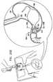
- Fig. 1depicts floating gastrointestinal anchor 1, in accordance with an embodiment of the present invention.
- anchor 1has a generally "C" or "U” shape.
- the anchorhas a distal end 2, a proximal end 4, and a side wall 5.
- the distal endis preferentially tapered for ease of insertion.
- Proximal end 4is shaped so as to define an aperture 6 opening into a central core 7, which extends through substantially the entire length of the anchor.
- the distal endmay be either open or closed.
- the distal endis typically tapered.
- a rigid insertion rod 8(described hereinbelow with reference to Fig. 7 ) is inserted into aperture 6 and central core 7 during insertion of the anchor into the subject.
- Anchor 1is made of a material that is flexible enough to be straightened, but has an elastic "memory" to conform to a pre-selected bent shape.
- the elastic memorymay be imparted by the material itself, or alternatively, by the addition of another material.
- the shape to which the anchor revertsmay be determined by the inclusion of an additional material having a memory such as spring steel or a plastic insert.
- the anchor materialcomprises a biocompatible material that can withstand the acid environment of the stomach, as is well known to those skilled in the art.
- a balloon 10located approximately midway between the distal end and the proximal end of the anchor.
- Balloon 10is shown in Fig. 1 in its deflated state.
- the balloonis typically manufactured of biocompatible material that can withstand the acid environment of the gastric lumen.
- a conduit channel 11is typically formed in side wall 5 of the anchor. This conduit channel allows for a thin-walled conduit (not shown) to pass along the side wall of the anchor and into the interior space of balloon 10 for eventual inflation thereof.
- a guidewire canal 12is typically formed in the wall of anchor 1 for inserting a guidewire during insertion of the anchor into the stomach.
- an overtubemay be used in lieu of a guidewire during insertion of the anchor into the gastrointestinal tract. If the diameter of the anchor is sufficiently small, a biopsy channel of an endoscope may be used as an overtube to direct the anchor into the gastrointestinal tract.
- balloon 10may be located with respect to the anchor at the proximal or distal ends or at any site therebetween.
- Figs. 2 and 3are a side view and a cross-sectional view, respectively, of another configuration of anchor 1 of Fig. 1 , in accordance with an embodiment of the present invention.
- conduit channel 11 of Fig. 1has been replaced with a conduit canal 14 formed within side wall 5 of anchor 1.
- side wall 5 of the anchoris shaped so as define guidewire canal 12, to allow passage of a guidewire, such as a standard guidewire, e.g., a standard .028 inch guidewire, as is well known in the art (as shown in Fig. 3 ).
- Fig. 4shows anchor 1 of Fig. 2 with a thin-walled conduit 16 inserted into conduit canal 14 of side wall 5 of the anchor and threaded into the interior of balloon 10.
- conduit 16is inserted into conduit channel 11 of side wall 5, as described hereinabove with reference to Fig. 1 .
- Balloon 10is shown in its inflated state in Fig. 4 .
- a proximal end 18 of conduit 16extends a sufficient distance, for example 60 cm, to allow passage of the conduit out of the mouth of the subject while the anchor with the inflated balloon is in the gastric lumen.
- a fitting 20is at proximal end 18 of the conduit 16.
- Fitting 20typically comprises a "luer-lock” type or equivalent self-sealing mechanism, as is well known to those skilled in the art, for allowing inflation of a balloon in a sealed system.
- the insertion of the balloon into the stomachpromotes a feeling of satiety in the subject and generally interferes with peristaltic waves and gastric emptying.
- conduit 16is wrapped around an external surface of anchor 1, rather than passed through conduit canal 14 of Fig. 2 or conduit channel 11 of Fig. 1 .
- anchor 1typically is shaped so as to define neither conduit canal 14 nor channel 11.
- the caliber of the conduit and its lumenare typically sufficient to allow inflation of any balloon.
- the conduitcomprises a biocompatible material that can withstand the acid environment, and can flex with the anchor in its different conformations.
- the balloon(s)are inflated to a volume sufficient to fill or partially fill the gastric lumen, which is typically between about 400 and about 1000 cc, depending on stomach size.
- the anchortypically has external markings from the end of the tapered tip, e.g., every 5 cm, to help guide the operator.
- Fig. 5shows an anchor 22, in accordance with an embodiment of the present invention. Except as described below, anchor 22 is generally similar to anchor 1, described hereinabove with reference to Figs. 1-4 .
- Anchor 22is shaped so as to have an "S" configuration, and comprises two or more balloons, e.g., a distal balloon 24 and a proximal balloon 26. For some applications, anchor 22 is shaped so as not to include the portion of the anchor proximal to the proximal balloon. In the multi-balloon configuration shown in Fig. 5 , a corresponding number of respective canals are used for guiding conduits into the respective interiors of the balloons.
- a distal canal 28guides distal conduit 30 to distal balloon 24, and a proximal canal 32 guides proximal conduit 34 to proximal balloon 26. If more than two balloons are provided, a corresponding number of conduits are used in the same manner.
- the inflation portsare marked proximal and distal in such a way that is easily recognizable to an endoscopist upon viewing in the gastric lumen.
- Fig. 6shows anchor 22 of Fig. 5 with the proximal and distal balloons in their inflated state.
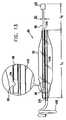
- Fig. 7is a side view of anchor 1 in a straightened position prior to insertion into the gastrointestinal tract, in accordance with an embodiment of the present invention.
- Rigid rod 8is typically extended through the entire length of central core 7 of anchor 1, causing anchor 1 to assume a generally straight configuration. (Alternatively, the rigid rod is extended through only a portion of the length of the central core.)
- a pushing catheter 36having a proximal end 37 and a distal end 38 is shown in axial alignment with anchor 1, The pushing catheter 36 has a bore 39 extending entirely therethrough.
- Rod 8extends entirely through bore 39 and outside of proximal end 37 of the pushing catheter.
- Rigid rod 8typically comprises a rigid unbendable biocompatible material, which easily slips in and out of the pushing catheter.
- the rigid rodcomprises a generally rigid biocompatible material, which, although slightly bendable, is sufficiently rigid to as to easily slip in and out of the pushing catheter.
- Rigid rod 8is sufficiently long to fully engage bore 39 of pushing catheter 36, and to extend out of distal end 38 of pushing catheter 36 by between about 35 and about 55 cm, e.g., by approximately 40 cm or approximately 45 cm, for the C-shaped configuration described hereinabove with reference to Figs. 1-4 .
- the distal portion of rod 8 which extends past distal end 38 of pushing catheter 36is inserted into central core 7 of anchor 1.
- rod 8When used with other configurations, such as the S-shaped configuration described hereinabove with reference to Figs. 5 and 6 , or the helical configuration described hereinbelow with reference to Figs. 12A-B , rod 8 has a length appropriate for the length of the core of these configurations.
- a pushing tab 40is preferentially provided in a vicinity of proximal end 37 of the pushing catheter.
- Tab 40is used by the endoscopist to push anchor 1 off rod 8, by pushing the tab forward while holding the proximal end of rod 8 stationary with respect to the mouth of the subject.
- the pushing cathetertypically comprises a biocompatible rigid unbendable material, or a generally rigid, but slightly bendable material.
- anchor 1After anchor 1 has been inserted into the gastrointestinal tract and the straightening rod has been removed, the anchor assumes its "C", "S", "U”, or any other pre-selected bent shape that the anchor has been configured to assume. By assuming a pre-selected bent shape, the anchor generally prevents migration of the inserted device.
- the anchor materialis flexible enough to enable straightening for deployment, and has a memory shape that remains after rod 8 has been removed. In this way, it facilitates safe atraumatic endoscopic removal, even after having assumed its memory shape.
- anchor 1may be partially or completely straightened during removal. Anchor 1 allows carriage of one or more balloons, transmitters, cameras, or any other device that is desired to be placed in the gastric lumen.
- Anchor 1when in the C-configuration described hereinabove with reference to Figs. 1-4 , typically has a total length of between about 30 and about 55 cm, e.g., approximately 40 cm.
- a central, generally straight, portiontypically has a length of between about 15 and about 25 cm, e.g., approximately 16 cm or approximately 20 cm, and each end portion typically has a length of between about 8 and about 15 cm, e.g., approximately 10 cm or approximately 12 cm.
- These dimensionsmay, of course, vary depending on stomach shape and size. Other areas of the gastrointestinal tract require various shapes and sizes.
- distal end 2 of anchor 1is closed and is tapered with a soft flexible tip to allow easy passage through the gastrointestinal tract.
- Fig. 8illustrates an appendage 42 attached to distal end 2 of anchor 1, in accordance with an embodiment of the present invention.
- Appendage 42may also be attached to distal end 2 of anchor 22, described hereinabove with reference to Figs. 5-6 (configuration now shown).
- Appendage 42comprises a wire 45 that is housed in a flexible shaft 44.
- the appendageis preferably an elongated continuation of distal tip 2, comprising the same material as distal tip 2.
- the appendageis preferably string-like and approximately 3-5 mm in diameter.
- Wire 45 housed thereinis typically a unitary piece, which typically comprises a first relatively short relatively flexible segment 46 (e.g., having a length of approximately 5 cm).
- Wire 45alternatively comprises a different arrangement of alternating flexible and stiff segments, each having various lengths.
- appendage 42When balloon 10 is in its deflated state, appendage 42 typically assumes the position shown in Fig. 8 , such that a distal end 52 of appendage 42 is positioned in a vicinity of proximal end 4 of anchor 1 (for clarity of illustration, balloon 10 is not shown in Fig. 8 ; the balloon can be seen in its deflated state in Fig. 1 , for example). In this position, appendage 42 provides additional safety for the device when balloon 10 is not inflated. Appendage 42 closes off the gap between proximal end 4 and distal end 2 of anchor 1, thereby preventing any undesired migration out of the stomach and into the pylorus. When balloon 10 is inflated, as shown, for example, in Fig. 4 , appendage 42 is easily displaced by the balloon (such that distal end 52 of appendage 42 is no longer positioned in the vicinity of proximal end 4 of anchor 1).
- Figs. 9 and 10illustrate an attachment 60 coupled to anchor 1, in accordance with respective embodiments of the present invention.
- Attachment 60may also be attached to anchor 22, described hereinabove with reference to Figs. 5-6 (configuration not shown).
- Attachment 60comprises one or more elements 48, which may comprise, for example, cord, ribbon, sponges, other thin material, or a combination thereof Elements 48 typically comprise a biocompatible material.
- Attachment 60is adapted to occupy all or a portion of the antrum, thereby interfering with gastric emptying.
- attachment 60may be coupled to a central portion of anchor 1, for example.
- attachment 60is used in combination with balloon 10.
- attachment 60may be coupled to a lateral arm of anchor 1, for example.
- Fig. 11illustrates a device 70 connected to anchor 1, in accordance with an embodiment of the present invention.
- Device 70comprises a transmitting device or any other device, such as a camera which could be placed separately, or in combination with any other device, such as balloon 10 (as shown in Fig. 11 ).
- Device 70may also comprise another type of therapeutic device; for example, device 50 may comprise a device for administering medication or a device for targeting a tumor.
- device 70is adapted to administer chemotherapy, radiation therapy, photodynamic therapy, tumor ablation therapy, seed implant therapy, or any other anti-tumor therapy known to those skilled in the art.
- Figs. 12A and 12Billustrate a configuration of anchor 1 in which the anchor assumes the bent shape of a helix at its distal end, in accordance with an embodiment of the present invention.
- conduit canal 14is placed within central core 7.
- Balloon 10may be inflated in the conventional manner.
- the diameter of the helixis typically such that it is not able to pass through the pylorus, for example, between about 4 cm and about 20 cm, e.g., between about 8 cm and about 14 cm.
- a deviceis coupled to the straight length of the anchor, such as a therapeutic device, e.g., balloon 10; a transmitting device, e.g., a camera or other transmitting device; or other therapeutic device 70.
- a proximal end of the anchorhas a curved tip (e.g., assumes the bent shape of a helix), which generally diminishes tissue trauma by creating an atraumatic surface.
- Distal end 2 of the anchors described hereinabove with reference to Figs. 1-12Bis typically not tapered, but rather is rounded to prevent tissue damage upon contact.
- the anchortypically has an approximately 7-35 Fr caliber, e.g., an approximately 7-20 Fr or an approximately 25-35 Fr caliber.
- an interior surface of the anchorcomprises a biocompatible material different from that of the remainder of the anchor, in order to allow passage of rod 8 and/or for shape maintenance.
- the anchortypically has a smaller caliber, e.g., approximately 6 to 16 Fr.
- central core 7 of the anchoris used for a guidewire or for a combination guidewire/straightening rod.
- deployment of the gastrointestinal devices described hereinis performed using a gastric overtube or over a guidewire.
- These standard, well-established techniquesare adapted for use with the novel techniques and devices described herein.
- the guidewire methodhas been described in the upper gastrointestinal tract with reference to esophageal strictures.
- techniquesmay be used that are described in the above-mentioned articles by Kadakia SC et al., Fleischer DE et al., and/or Dumon JR et al., mutatis mutandis, including techniques for esophageal dilators passed over guidewires without the need for fluoroscopy.
- the anchors described hereinare deployed using the Savary system guidewire technique described by Dumor JR et al., modified as described immediately hereinbelow.
- Upper endoscopyis performed with complete evaluation of the esophagus stomach and duodenum.
- the endoscopistmeasures the distance from the incisors to the gastro-esophageal junction.
- the guidewireWith the endoscope in the gastric antrum, the guidewire (flexible tip first) is passed under direct vision into the gastric antrum.
- the guidewireis advanced as the endoscope is removed leaving the guidewire in the gastric lumen.
- the free end of the guidewire(outside of the mouth) is then placed into the guidewire lumen of the anchor.
- the anchoris slid down over the guidewire (without changing the position of the guidewire relative to the mouth) and passed into the mouth down the esophagus.
- the pushing tab of the pushing catheteris pushed forward while holding the rod stationary relative to the mouth of the subject.
- the conduit inflation portis then accessed with a luer-lock syringe and inflated with approximately 400-1000 cc of fluid, depending on stomach size, which can be viewed endoscopically. This is repeated for embodiments of the anchor that comprise multiple balloons.
- the conduit tubingis then pulled down into the stomach using a snare, hook catheter, grabbing forceps, or equivalent. Once the conduit tubing is in the gastric lumen, the endoscope is then removed and the procedure is complete.
- endoscopy with snare, hook catheter, grabbing forceps, or equivalent access of the free end of the conduit tubingcan be performed.
- the conduitis pulled out of the mouth and inflation or deflation performed, followed by pulling the free end of the conduit into the gastric lumen as described above.
- the embodiments described hereinmay be placed into the gastrointestinal tract using numerous methods for insertion.
- the anchors described hereinare deployed using a standard gastric overtube method, modified as described immediately hereinbelow.
- Standard endoscopyis performed with inspection of the esophagus stomach and duodenum.
- the endoscopeis then removed and a gastric overtube is placed, typically using ordinary techniques. Techniques are typically used that are described in the above-mentioned article by Werth et al., for use of a gastric overtube for foreign body removal and for multiple endoscopic intubations.
- the anchoris placed through the overtube.
- the pushing catheter tabis pushed once the distal tip of the anchor is 6-8 cm beyond the gastro-esophageal junction.
- the rod and pushing catheterare removed.
- the endoscopecan then pass through the overtube and inspect the anchor position, as described hereinabove. The remainder of the procedure is the same as the guidewire procedure described hereinabove.
- the anchorhaving reverted to its pre-selected bent shape, prevents a deflated balloon from migrating, thereby providing a safe weight loss device.
- the anchorcan be used to anchor more than one balloon, and can anchor any device that needs to remain in the gastric lumen.
- the anchorcan be used in a post-bariatric surgical subject whose weight loss has plateaued and who wishes further weight loss. It can be used anywhere in the gastrointestinal tract where a device of any kind needs to remain in place.
- the site of the anchorwill determine its pre-determined shape, geometry, and size. It is typically placed endoscopically and removed endoscopically under conscious sedation in an outpatient setting.
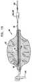
- Figs. 13-16are schematic illustrations of obesity treatment apparatus 90 comprising a balloon 92 and a floating gastrointestinal anchor 102 coupled thereto, in accordance with an embodiment of the present invention.
- techniques described hereinabove with respect to other anchors and balloonsmay be used with apparatus 90, mutatis mutandis.
- a highly-stretchable inflation tube 96protrudes from a first end of balloon 92, typically by a length L2 of about 1-6 cm (e.g., about 2-4 cm).
- a length L1 of tube 96 of about 6-12 cm (e.g., about 8-9 cm)remains within balloon 92.
- Tube 96typically comprises silicone or other stretchable elastomer, or another biocompatible material capable of stretching to at least about 2.5-10 times its original length (e.g., 6 times its original length).
- Inflation tube 96is shown in Fig. 13 in an unstretched state, in which an outer diameter D1 thereof is typically about 2-4 mm, e.g., 3 mm.
- Inflation tube 96is disposed within a supporting tube 94, which is typically bendable and resilient, and comprises silicone or another suitable material.
- Support tube 94is typically fixed to balloon 92 at either end using a sealant 104, which typically comprises a silicone-based or other biocompatible adhesive.
- An inflation hole 98 in support tube 94, and optionally in inflation tube 96,provides fluid communication between the lumen of balloon 92 and the lumen of tube 96.
- a closure mechanism 120typically comprising a luer lock and/or a hand-tightened cap maintains pressure within balloon 92 by preventing fluid leakage therefrom into the subject's stomach.
- a rod insertion tube 100allows insertion of a rigid rod (like rod 8 described hereinabove with reference to Fig. 7 ) to straighten anchor 102 at the time of implantation of apparatus 90.
- a rigid rodlike rod 8 described hereinabove with reference to Fig. 7
- anchor 102assumes an anchoring shape (e.g., the helical shape shown in Fig. 13 ).
- Anchor 102typically but not necessarily remains in the antrum, adjacent to the pyloric valve, and to some extent slows passage of chyme into the duodenum and thereby enhances the sensation of satiety.
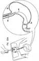
- Fig. 13schematically shows balloon 92 in a partially inflated state, as it may be in the stomach during an initial trial period designed to ascertain whether that level of inflation is sufficient to treat the subject's obesity. If it is determined that the inflation of the balloon is not sufficient, e.g., if the subject is not losing sufficient weight, then balloon 92 is further inflated, as shown in Figs. 14-16 . Similarly, if over the long term the level of inflation of the balloon decreases, then the balloon may be further inflated as shown in Figs. 14-16 .
- an endoscopic extraction tool 110couples with closure mechanism 120 or with inflation tube 96, using techniques known in the art, and stretches inflation tube 96 such that it withdraws closure mechanism 120 out of the stomach, through the subject's esophagus, and into (or out of) the subject's mouth. Due to this stretching, the outer diameter of inflation tube 96 decreases to a new diameter D2, smaller than D 1. If inflation tube 96 in this stretched state is able to facilitate re-inflation of balloon 92, then closure mechanism 120 is opened while in or just outside of the subject's mouth, and balloon 92 is inflated via inflation tube 96.
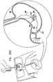
- a temporary filling tube 132is coupled to closure mechanism 120 or to a temporary coupling valve 130, in order to provide fluid communication between tubes 96 and 132.
- Inflation tube 96is gradually returned to the stomach, substantially returning its diameter to D2, and the balloon is inflated by fluid passing through temporary filling tube 132 and inflation tube 96.
- temporary filling tube 132is decoupled from inflation tube 96, and closure mechanism 120 is closed, in order to maintain the balloon in its newly inflated state, as shown in Fig. 16 .
- Figs. 17A and 17Bare schematic illustrations of a bend-limiting tube 140 for placement into gastrointestinal anchor 102 or another anchor, in accordance with an embodiment of the present invention.
- Bend-limiting tube 140typically but not necessarily comprises stainless steel, and is shaped to define a plurality of slits 142 which permit tube 140 to assume a straight position, or to bend up to a predefined limit.
- the dimensions of slits 142may differ from those shown in Figs. 17A and 17B .
- theycould be configured to allow more or less bending of bend-limiting tube 140.
- slits 142are shown to be on only one side of bend-limiting tube 140, for some applications the slits are placed in different positions from those shown, so as to, for example, permit limited back and forth flexing of tube 140, or bending in any direction.
- slits 142are placed on tube 140 so as to allow anchor 102 to assume the position shown in Fig. 15 , but to inhibit excess curvature of anchor 102 to develop.
- bend-limiting tube 140is replaced or supplemented by other bend-limiting tubes for inhibiting excess bending.
- a series of chained or free beadsmay be disposed within a bend-limiting tube running along the length of anchor 102, and the close proximity of the beads to each other may be used to limit local bending.
- the beadsmay comprise spherical beads or shaped beads with protrusions, so as to limit bending of the anchor.
- a bend-limiting tube placed within anchor 102, or running along the length of anchor 102comprises multiple closely-spaced rings surrounding the bend-limiting tube, whereby excess bending of the bend-limiting tube and the anchor is prevented by contact of the rings.
- proximal end 210 of anchor 200is typically, but not necessarily, coupled to a device, such as a therapeutic device, e.g., a balloon; a transmitting device, e.g., a camera or other transmitting device; or other therapeutic device.
- proximal end 210may be coupled to a balloon such as balloon 92, described hereinabove with reference to Figs. 13-16 .
- Anchor 200may alternatively or additionally be used in combination with other techniques described hereinabove.
- Anchor 200typically, but not necessarily, is positioned in an antrum 212, adjacent to the pyloric valve, and to some extent interferes with natural antral contractions, thereby slowing gastric emptying and enhancing the sensation of satiety.
- Anchor 200comprises a flexible tube 220, which, in its relaxed position, is typically shaped so as to define a generally planar base portion 222, and a proximal portion 224 that projects away from the plane defined by base portion 222, typically in an approximately perpendicular direction.
- base portion 222is generally circular.
- portion 22has another shape, such as a rectangle, e.g., a square, or an ellipse. It is noted that the shape described herein and shown in Fig. 18 reflects anchor 200 when it is in its relaxed position. When deployed in the stomach, the shape of the anchor may change because of forces applied thereto by the stomach wall.
- tube 220comprises silicone, nylon, Pebax® (Arkema), Teflon® (DuPont), stainless steel, nitinol, titanium, or another biocompatible material.
- Anchor 200further comprises at least two cross-bar elements 230, the ends of which are positioned in a vicinity of base portion 222.
- the anchorcomprises exactly two cross-bar elements
- the two elementsare typically approximately perpendicular to one another when the anchor is in its relaxed position, as shown in Fig. 18 .
- the cross-bar elementshelp maintain the shape of the anchor, so that the anchor interferes with gastric emptying, as mentioned above, and so that the anchor does not pass into a duodenum of the subject.
- cross-bar elements 230comprise a rigid material, such as metal (e.g., stainless steel), or nylon, Pebax® (Arkema), Teflon® (DuPont), or another similar material, with or without metal inserts, while for other applications the elements comprise a more flexible, but still generally rigid, material, such as plastic or silicone.
- each of cross-bar elements 230is shaped so as to define a lumen therethrough, and comprises an elastic coupling band 232 that passes through the lumen. Two portions of each of coupling bands 232 protrude from the cross-bar element, and are coupled to base portion 222 at two respective points that are approximately opposite one another. For some applications, bands 232 are generally rigid in central areas thereof, while elastic near the ends thereof.
- cross-bar elements 230do not comprise coupling bands 232, and are instead coupled directly to base portion 222. Further alternatively, exactly one end of each cross-bar element is coupled directly to base portion 222.
- respective central portions 240 of cross-bar elements 230are shaped so as to define respective cut-outs 242, which better enable the cross-bar elements to occupy approximately the same plane.
- the central portionsare shaped to define indentions that are not cut out.
- the cross-bar elementsare slightly arced in opposite directions, so as to allow the cross-bar elements to intersect one another while remaining approximately in a single plane.
- the cross-bar elementsare shaped like simple cylinders.
- anchor 200further comprises sleeves 244, each of which encloses a respective cross-bar element 230 and all or a portion of the respective coupling band 232 that protrudes from the cross-bar element.
- the ends of the sleevesare typically coupled to base portion 222 at the points at which the respective coupling bands are coupled (e.g., as shown in Fig. 19 ).
- each sleeveserves as a backup in the event that the respective coupling band 232 fails.
- sleeves 244are coupled to the respective bands or to cross-bar elements 230. In either case, sleeves 244 typically help prevent the contents of the stomach from entering cross-bar elements 230. (For the sake of clarity, sleeves 244 are not shown in Figs. 20A-D , although they may be provided.)
- base portion 222For applications in which base portion 222 is generally circular, the base portion typically has a diameter of between about 5 and about 10 cm, such as about 7 cm, and cross-bar elements 230 have corresponding lengths.
- Tube 220 of base portion 222typically has a cross-sectional outer diameter of between about 5 and about 10 mm, such as about 8 mm.
- the cross-bar elementstypically have a cross-sectional outer diameter of between about 4 and about 10 mm, such as about 6 mm.
- Fig. 19is a schematic illustration of anchor 200 in a stretched position, in accordance with an embodiment of the present invention.
- the anchorIn order to enable transesophageal insertion of anchor 200 using a gastroscope, the anchor is typically stretched until it assumes an elongated position, in which tube 220 is generally straight.
- Elastic coupling bands 232 of cross-bar elements 230enable the anchor to assume this elongated position, in which the cross-bar elements are displaced from their relaxed positions until they are approximately parallel with tube 220.
- a generally stiff rodis inserted into a lumen of tube 220, in order to maintain the stretched position during insertion (rod not shown in figures). Once the anchor has been partially or completely positioned in the stomach, the rod is removed, allowing the anchor to assume its relaxed position.
- Figs. 20A-Dare schematic illustrations of the deployment of anchor 200, in accordance with an embodiment of the present invention.
- a guidewire 252is transesophageally inserted into a stomach 250, such as using an gastroscope, as is known in the art.
- the distal end of the guidewireis maneuvered to antrum 212, and the gastroscope is removed from the subject.
- Anchor 200is configured to assume its elongated position, by inserting the generally stiff rod into the lumen of tube 220, as described hereinabove with reference to Fig. 19 .
- the elongated anchoris transesophageally inserted into stomach 250 over guidewire 252, which passes through a lumen of the elongating rod.
- anchor 200is allowed to gradually return to its relaxed position, by withdrawal of the rod.
- Withdrawal of the rodtypically includes pushing a portion of the implantable apparatus (e.g., balloon 260 or anchor 200) off of the rod.
- a distal tip of a pushing tool(not shown) is coupled to the portion of the implantable apparatus such that, if desired, the pushing tool can also at least partially pull the portion of the implantable apparatus back onto the rod.
- the pushing tooltypically grasps or is otherwise releasably coupled to the portion of the implantable apparatus, and can be released by the physician from the portion when the rod is sufficiently withdrawn.
- Anchor 200is shown partially relaxed in Fig.
- anchor 200is coupled to a balloon 260, such as balloon 92, described hereinabove with reference to Figs. 13-16 .
- balloon 260has been fully inflated, anchor 200 is positioned in antrum 212, and guidewire 252 is withdrawn from the subject.
- a gastroscopeis used for visually confirming proper placement and deployment of the anchor and/or inflation of balloon 260.
- the scope of the present inventionincludes the use of any of the anchors described hereinabove without simultaneous use of a balloon.
- the anchortypically slows gastric emptying and/or fills space and thereby induces a sensation of satiety.
- generally helical anchors described hereinabove and shown in the figuresmay include more turns, for example so as to occupy half of the stomach or even substantially all of the stomach (instead of just the portion near the antrum, as shown in some of the figures).
- Embodiments described hereinmay be practiced in combination with techniques described in one or more of the following applications, which are assigned to the assignee of the present patent application US Patent Application 11/132,855, filed May 18, 2005 ; US Provisional Patent Application 60/639,843, filed December 27, 2004 ; PCT Patent Application PCT/IL2005/001381, filed December 27, 2005 ; US Provisional Patent application 60/787,124 filed by Brooks on March 28, 2006, entitled, "Floating gastrointestinal anchor”; and US Provisional Patent application 60/815,624 filed by Brooks on June 20, 2006, entitled, "Floating gastrointestinal anchor.”
Landscapes
- Health & Medical Sciences (AREA)
- Vascular Medicine (AREA)
- Animal Behavior & Ethology (AREA)
- Nursing (AREA)
- Orthopedic Medicine & Surgery (AREA)
- Engineering & Computer Science (AREA)
- Biomedical Technology (AREA)
- Obesity (AREA)
- Heart & Thoracic Surgery (AREA)
- Life Sciences & Earth Sciences (AREA)
- Child & Adolescent Psychology (AREA)
- General Health & Medical Sciences (AREA)
- Public Health (AREA)
- Veterinary Medicine (AREA)
- Media Introduction/Drainage Providing Device (AREA)
- Surgical Instruments (AREA)
- Prostheses (AREA)
Description
- The present invention generally relates to implantable medical apparatus. Specifically, the present invention relates to apparatus for implantation in the gastrointestinal tract. An apparatus according to the preamble of
claim 1 is known for example fromUS 2005/0216040 . - Morbid obesity remains an ever-growing problem in the U.S. Varying forms of gastric bypass surgery have developed and have improved over the last few decades. Recently, laparoscopic gastric banding has emerged as a less invasive surgical option. However, bariatric surgery is fraught with morbidity of up to 20%, with a re-operation rate approaching 25% at 3-5 years post-op. Bariatric surgery carries an operative mortality of 0.5%. Diet and pharmaceutical alternatives have not been very effective, with a high recidivism rate. Today, the Bioenterics® intragastric balloon (BIB®) (Inamed Corporation, Santa Barbara, California, USA) is in use outside of the U.S., achieving average weight loss of 15 kg and 5 point drop in BMI. However, an 8-9% balloon deflation rate has resulted in unwarranted migration leading to obstruction.
- PCT Patent Publication
WO 06/070361 to Brooks US Patent Application Publication 2004/0044357 to Gannoe et al. , describes gastric space occupying devices that include a stent configured for deployment in the gastrointestinal tract of a patient, and in particular, for deployment in the esophagus or the stomach. Secured to the stent is an expandable member that is adapted to reside within the patient's stomach. When expanded, the expandable member occupies a predefined volume within the patient's stomach and is further tethered to the deployed stent, thereby retaining or anchoring the expandable member within the stomach. Methods and systems for the deploying the space occupying devices are also described.PCT Publication WO 05/107641 US Patent Application Publication 2005/0267596 , andUS Patent Application Publication 2005/0267595 to Chen et al. , describe a gastric balloon that includes a scaffold structure, one or more internal inflatable compartments within the scaffold structure, and one or more inflatable bladders formed over the space-filling compartment. The gastric balloon may be deployed transesophageally using a gastroscope, and is inflatedin situ, preferably using a combination of liquid and gas inflation media.PCT Publication WO 05/009288 US Patent Application Publication 2005/0033331 to Burnett et al. , describe techniques for facilitating intermittent and/or partial obstruction of a pyloric valve. Devices described generally include a support portion for preventing the device from passing through the pyloric valve, and a tissue engagement portion for contacting tissue adjacent the pyloric valve to obstruct the valve. Some embodiments also include a positioning member extending from the tissue engagement portion for helping position the device for obstructing the valve. A retaining member may optionally be included on the distal end of the positioning member for further maintaining a position of the device in the stomach. Some embodiments are deliverable into the stomach through the esophagus, either by swallowing or through a delivery tube or catheter. Some embodiments are described as being fully reversible. Some embodiments self-expand within the stomach, while others are inflated or otherwise expanded.US Patent Application Publication 2005/0055039 to Burnett et al. , describes a device for performing one or more functions in a gastrointestinal tract of a patient, which includes an anchoring member and at least one actuator, sensor, or combination of both coupled with the anchoring device. The anchoring device is adapted to maintain at least part of the device within a pyloric portion of the patient's stomach and to intermittently engage, without directly attaching to, stomach tissue. Actuators perform any suitable function, such as transmitting energy to tissue, acting as a sleeve to reduce nutrient absorption, occupying space in the stomach, eluting a drug and/or the like. Sensors may be adapted to sense any suitable patient characteristic within the patient's gastrointestinal tract, such as pH, temperature, bile content, nutrient content, fats, sugars, alcohol, opiates, drugs, analytes, electrolytes and/or hemoglobin.US Patent Application Publication 2006/0020278 to Burnett et al. , describes methods, devices and systems which facilitate gastric retention of a variety of therapeutic devices. Devices generally include a support portion for preventing the device from passing through the pyloric valve or esophagus. A retaining member may optionally be included on the distal end of the positioning member and is described to maintain a position of the device in the stomach. Some embodiments are deliverable into the stomach through the esophagus, either by swallowing or through a delivery tube or catheter. Some embodiments are fully reversible. Some embodiments self-expand within the stomach, while others are inflated or otherwise expanded.PCT Publication WO 05/094257 to Birk - The following patents and patent application publications, may be of interest:
- US Patent
United States Patent 7,033,384 to Gannoe, et al. US Patent Application Publication 2006/0190019 to Gannoe et al. US Patent Application Publication 2002/0055757 to Torre et al. US Patent Application Publication 2005/0228504 to Demarais US Patent Application Publication 2005/0085923 to Levine et al. US Patent Application Publication 2005/0192614 to Binmoeller US Patent Application Publication 2004/0267378 to Gazi et al. US Patent 4,416,267 to Garren et al. US Patent 4,925,446 to Garay et al. US Patent 5,052,998 to Zimmon PCT Publication WO 05/039457 to Paganon et al. PCT Publication WO 04/089262 to Paganon Canadian Patent Application Publication 2483335 to Byrum et al. US Patent Application Publication 2005/0070937 to Jambor et al. US Patent Application Publication 20005/004430 to Lee et al. PCT Publication WO 04/105622 to Ritchie US Patent Application Publication 2004/088008 to Gannoe et al. PCT Publication WO 04/014237 to Gannoe et al. US Patent Application Publication 2004/093091 to Gannoe et al. US Patent Application Publication 2004/059289 to Garza et al. PCT Publication WO 03/095015 to Alverdy European Patent Application Publication EP 1342458 to Creusy et al. US Patent Application Publication 2003/158569 to Wazne PCT Publication WO 03/055420 to Lointier et al. US Patent 6,656,194 to Gannoe et al. US Patent Application Publication 2003/171768 to McGhan PCT Publication WO 02/40081 to Bales et al. PCT Publication WO 01/66166 to Birk PCT Publication WO 98/56321 to Pier et al. US Patent 5,234,454 to Bangs - Canadian Patent Application Publication
CA 2068715 to Kuzmak US Patent 4,696,288 to Kuzmak et al .US Patent 5,129,915 to Cantenys US Patent 5,084,061 to Gau et al. US Patent 4,908,011 to Jacobsen et al. - European Patent Application Publication
EP 0246999 to Eshel et al. PCT Publication WO 87/00034 to Taylor US Patent 4,739,758 to Lai et al. PCT Publication WO 86/06611 to Kullas et al. US Patent 4,694,827 to Weiner et al. - German Patent Application Publication
DE 3540936 to Stricker et al. - British Patent Application Publication
GB 2139902 to Celestin et al. - Canadian Patent Application Publication
CA 1233387 to Garren et al. US Patent 4,899,747 to Garren et al. - German Patent Application Publication
DE 3326061 to Woerner - German Patent Application Publication
DE 3310234 to Husfeldt - Italian Patent
IT 1235492 to Frimberger et al. US Patent 4,485,805 to Foster - German Patent Application Publication
DE 3227585 to Woerner US Patent 4,416,267 to Garren et al. US Patent 4,315,509 to Smit US Patent 7,004,176 to Lau - The following articles, may be of interest:
- Kadakia SC et al., "Esophageal dilation with polyvinyl bougies using a marked guidewire without the aid of fluoroscopy," Am J Gastro 88:1381-86 (1993)
- Fleischer DE et al., "A marked guidewire facilitates esophageal dilation," Am J Gastro 84:359-61 (1989)
- Dumon JR et al., "A new method of esophageal dilation using Savary-Gilliard bougies," Gastro Endosc 31:379-82 (1985)
- Werth et al., "A safe and quick method for endoscopic retrieval of multiple gastric foreign bodies using a protective sheath," Surg Gynecol Obstet 171(5):419-20 (1990)
- According to one aspect of the invention, a flexible tubular anchor having an elastic memory for assuming a pre-selected bent configuration is described for placement in the gastrointestinal tract. The anchor comprises a distal end and an open proximal end having a central core extending toward the distal end. When the core receives a straightening rod therethrough, the anchor is straightened from its pre-selected bent shape.
- In accordance with another aspect of the invention, a method of inserting a flexible tubular anchor in a subject's gastrointestinal tract is described. The anchor has an elastic memory for assuming a pre-selected bent shape and has a distal end, an open proximal end having a central core extending toward the distal end, a balloon sealed along a portion of the anchor, an inflation conduit extending from the proximal end to the interior of the balloon, a pushing catheter having a bore therethrough axially aligned with the anchor, and a straightening rod extending through said catheter and the anchor. The method generally comprises inserting the anchor in its straightened configuration into the subject's stomach, separating the anchor from the straightening rod thereby allowing the anchor to assume its pre-selected bent shape, and then inflating the balloon.
- In some embodiments of the present invention, a floating gastrointestinal anchor comprises a flexible tube, which, in its relaxed position, is shaped so as to define a generally planar base portion, and a proximal portion that projects away from the plane defined by the base portion, typically in an approximately perpendicular direction. The anchor further comprises at least two cross-bar elements, the ends of which are positioned in a vicinity of the base portion of the anchor. The cross-bar elements help maintain the shape of the anchor. The anchor typically, but not necessarily, is positioned in an antrum, adjacent to the pyloric valve, and to some extent interferes with natural antral contractions, thereby slowing gastric emptying and enhancing the sensation of satiety. The proximal portion of the anchor is typically, but not necessarily, coupled to a device, such as a therapeutic device, e.g., a balloon.
- Typically, each of the cross-bar elements is shaped so as to define a lumen therethrough, and comprises an elastic coupling band that passes through the lumen. Two portions of each of the coupling bands protrude from the cross-bar element, and are coupled to the base portion of the anchor at two respective points that are approximately opposite one another. In order to enable transesophageal insertion of the anchor using a gastroscope, the anchor is typically stretched until it assumes an elongated position, in which the tube thereof is generally straight. The elastic coupling bands of the cross-bar elements enable the anchor to assume this elongated position, in which the cross-bar elements are displaced from their relaxed positions until they are approximately parallel with the tube of the anchor. A generally stiff rod is inserted into a lumen of the tube, in order to maintain the stretched position during insertion. Once the anchor has been appropriately positioned in the stomach, the rod is removed, allowing the anchor to assume its relaxed position.
- As will be appreciated by those persons skilled in the art, a feature provided by some embodiments of the present invention is the ease in which an anchor may be inserted into the gastrointestinal system. Another feature provided by some embodiments of the present invention is the safety and security provided by the use of such an anchor. It is therefore an object of some embodiments of the present invention to provide a safe and easy method of inserting and securing a floating anchor into the gastrointestinal system so that a variety of devices may be safely secured therein. It is another object of some embodiments of the present invention to safely and securely anchor a balloon in the stomach for promoting a feeling of satiety in a subject. Additional objects of embodiments of the present invention will become apparent from the following description.
- There is therefore provided, in accordance with an embodiment of the present invention, apparatus for use in a gastrointestinal tract of a subject, the apparatus including:
- a straightening rod;
- a flexible tubular anchor having a distal end and an open proximal end, and sized to fit in the gastrointestinal tract, the anchor including a material that has an elastic memory which biases the anchor towards assuming a pre-selected bent configuration, the anchor shaped so as to define a central core extending from the open proximal end toward the distal end, and the anchor configured to be straightened from the pre-selected bent configuration by insertion of the straightening rod in the central core; and
- a device coupled to the anchor, selected from the list consisting of: a therapeutic device, and a transmitting device.
- For some applications, the distal end of the anchor is tapered. For some applications, the bent configuration is selected from the group consisting of: a C-shaped configuration, an S-shaped configuration, a U-shaped configuration, a helical configuration, and a sinusoidal configuration, and the material has the elastic memory which biases the anchor towards assuming the selected bent configuration.
- For some applications, the apparatus includes a pushing catheter shaped so as to define a bore therethrough, the catheter adapted to be axially aligned with the anchor, and the straightening rod is configured to be inserted through the catheter into the central core of the anchor.
- In an embodiment, the anchor is shaped so as to define a wall having a guide wire canal therein.
- In an embodiment, the device includes a transmitting device.
- In an embodiment, the anchor is adapted to interfere with gastric emptying of the subject.
- In an embodiment, the device includes the therapeutic device. For some applications, the therapeutic device includes string-like attachments. For some applications, the therapeutic device includes a medication administration device. For some applications, the therapeutic device is adapted to administer tumor-targeting therapy.
- In an embodiment, the therapeutic device includes an attachment adapted to interfere with gastric emptying of a stomach of the subject when the anchor is placed in the stomach.
- In an embodiment, the therapeutic device includes a balloon coupled to a balloon-coupling portion of the anchor. For some applications, the anchor includes a conduit wrapped around an external surface of the anchor, the conduit extending from the proximal end of the anchor to an interior of the balloon.
- In an embodiment, the balloon is adapted to promote a feeling of satiety in the subject. Alternatively or additionally, the balloon is adapted to interfere with peristaltic waves and gastric emptying of the subject.
- For some applications, the balloon includes a first balloon, and the therapeutic device includes a second balloon.
- In an embodiment, the balloon is positioned around the balloon-coupling portion of the anchor. For some applications, the anchor includes proximal and distal portions on respective sides of the balloon-coupling portion, and the balloon is coupled to the balloon-coupling portion and is not coupled to the proximal or distal portions. For some applications, a length of the balloon-coupling portion of the anchor is less than 75% of a total length of the anchor, such as less than 50% of the total length of the anchor.
- In an embodiment, the anchor is shaped so as to define a conduit channel extending from the proximal end of the anchor to an interior of the balloon. For some applications, the apparatus includes a conduit having distal and proximal ends, which is adapted to be placed through the conduit channel, such that the distal end opens to the interior of the balloon, and the proximal end opens outside of the anchor.
- In an embodiment, a distal portion of the anchor has a curved shape when the anchor assumes the bent configuration. For some applications, the distal portion of the anchor has a helical shape when the anchor assumes the bent configuration. For some applications, a proximal portion of the anchor has a helical shape when the anchor assumes the bent configuration.
- In an embodiment, a proximal portion of the anchor has a curved shape when the anchor assumes the bent configuration. For some applications, the proximal portion of the anchor has a helical shape when the anchor assumes the bent configuration.
- In an embodiment, the anchor includes an elongated appendage extending from the distal end thereof, the appendage having a distal end, the appendage configured to assume a position in which the distal end thereof is in a vicinity of the proximal end of the anchor when the anchor assumes the bent configuration. For some applications, the appendage includes a housing and a wire therein, and the wire includes a first flexible segment, a second relatively stiff segment, and a third relatively flexible segment. For some applications, the device includes a balloon coupled to the anchor, and the appendage is adapted to be displaced by the balloon when the balloon is inflated, such that the distal end of the appendage is not in the vicinity of the proximal end of the anchor.
- There is further provided, in accordance with an embodiment of the present invention, apparatus for use in a gastrointestinal tract of a subject, the apparatus including:
- a straightening rod;
- a flexible tubular anchor having a closed distal end and an open proximal end, the anchor including a material that has an elastic memory which biases the anchor towards assuming a pre-selected bent configuration, the anchor shaped so as to define a central core extending from the open proximal end toward the distal end, and the anchor configured to be straightened from the pre-selected bent configuration by insertion of the straightening rod in the central core.
- There is yet further provided, in accordance with an embodiment of the present invention, apparatus for use in a stomach of a subject, the apparatus including:
- an elongated biocompatible anchor having proximal and distal portions and a balloon-coupling portion therebetween, the anchor being sized to fit in the stomach; and
- a balloon coupled to the balloon-coupling portion of the anchor, and not to the proximal or distal portions.
- In an embodiment, the balloon is adapted to promote a feeling of satiety in the subject. Alternatively or additionally, the balloon is adapted to interfere with peristaltic waves and gastric emptying of the subject.
- In an embodiment, the anchor is adapted to interfere with gastric emptying of the subject.
- In an embodiment, the anchor is adapted to assume a pre-selected bent configuration when in the stomach.
- In an embodiment, the balloon is positioned around the balloon-coupling portion of the anchor. For some applications, a length of the balloon-coupling portion of the anchor is less than 75% of a total length of the anchor, such as less than 50% of the total length of the anchor.
- There is still further provided, in accordance with an embodiment of the present invention, a method including:
- straightening a flexible tubular anchor that includes a material that has an elastic memory which biases the anchor towards assuming a pre-selected bent configuration, by inserting a straightening rod into a central core extending from an open proximal end toward a distal end of the anchor;
- inserting the straightened anchor with the rod therein into a gastrointestinal tract of a subject; and
- removing the anchor from the rod, thereby allowing the anchor to assume the pre-selected bent configuration.
- For some applications, inserting the straightened anchor includes threading the anchor onto a guidewire. Alternatively, inserting the straightened anchor includes inserting the anchor into an overtube.
- For some applications, inserting the rod into the central core includes inserting the rod through a bore of a pushing catheter axially aligned with the anchor, and then into the central core, and removing the rod from the anchor includes pushing the anchor off the rod by pushing on the pushing catheter.
- For some applications, inflating the balloon includes inserting an inflation conduit into the gastrointestinal tract, and inflating the balloon via the inflation conduit. For some applications, inflating the balloon includes inflating the balloon via an inflation conduit that passes through the conduit channel.
- There is additionally provided, in accordance with an embodiment of the present invention, method including:
- inserting, into a stomach of a subject, an elongated anchor having proximal and distal portions and a balloon-coupling portion therebetween;
- inflating a balloon coupled to the balloon-coupling portion of the anchor, and not to the proximal or distal portions.
- There is also provided, in accordance with an embodiment of the invention, apparatus for use in a stomach of a subject, the apparatus including:
- a balloon, adapted for placement in the stomach;
- an anchor, coupled to the balloon and adapted to prevent the balloon from passing into a duodenum of the subject; and
- an inflation tube, coupled to the balloon to permit inflation of the balloon, and adapted to stretch from the stomach to a mouth of the subject to facilitate inflation of the balloon.
- In an embodiment, the inflation tube is adapted to stretch to more than 2.5 times a resting length thereof, e.g., from 2.5 to 10 times the resting length (such as six times the resting length).
- In an embodiment, the anchor includes a resilient tube, and the apparatus includes a bend-limiting tube coupled to the resilient tube, which limits an extent of bending of the resilient tube.
- In an embodiment, the inflation tube is configured to be disposed within the resilient tube, the resilient tube permitting the inflation tube to assume a straight position, or to bend up to a predefined limit.
- In an embodiment, the anchor includes a material that has an elastic memory which biases the anchor towards assuming a pre-selected bent configuration.
- In an embodiment, the apparatus includes a straightening rod, and:
- the anchor has a distal end and an open proximal end;
- the anchor is shaped so as to define a central core extending from the open proximal end toward the distal end; and
- the anchor is configured to be straightened from the pre-selected bent configuration by insertion of the straightening rod in the central core.
- In an embodiment, the balloon is adapted to promote a feeling of satiety in the subject.
- In an embodiment, the balloon is adapted to interfere with peristaltic waves and gastric emptying of the subject.
- In an embodiment, the apparatus includes a device coupled to the anchor, selected from the list consisting of: a therapeutic device, and a transmitting device.
- In an embodiment, the apparatus includes a closure mechanism coupled to a proximal end of the inflation tube, configured to maintain pressure within the balloon by preventing leakage of fluid therefrom into the stomach of the subject.
- In an embodiment, the apparatus includes an extraction tool configured to stretch the inflation tube by reversibly engaging and pulling on the inflation tube.
- In an embodiment, the apparatus includes a filling tube configured to be temporarily coupled to the inflation tube while the inflation tube is stretched, and configured to facilitate inflation of the balloon when the inflation tube is relaxed at least in part following being stretched.
- There is additionally provided, in accordance with an embodiment of the invention, a method, including:
- inserting into a stomach of a subject a gastric balloon in fluid communication with an inflation tube;
- assessing an inflation level of the balloon following insertion thereof;
- in response to identifying a need for inflation of the balloon, stretching the inflation tube while keeping the balloon within the stomach; and
- inflating the balloon following the stretching of the inflation tube.
- In an embodiment, assessing the inflation level of the balloon includes determining a level of weight loss of the subject and correlating weight loss to the level of inflation of the balloon.
- In an embodiment, inflating the balloon includes injecting a fluid into the inflation tube while a proximal end of the inflation tube is outside of a body of the subject.
- In an embodiment, the method includes temporarily coupling the inflation tube to a filling tube following the stretching of the inflation tube, and wherein inflating the balloon includes:
- allowing at least a portion of the inflation tube to return to the stomach while the filling tube is coupled to the inflation tube; and
- injecting a fluid into the inflation tube via the filling tube while the portion of the inflation tube remains disposed within the stomach.
- In an embodiment, stretching the inflation tube includes extracting a proximal portion of the inflation tube from a mouth of the subject.
- In an embodiment, extracting the proximal portion of the inflation tube includes stretching the inflation tube to at least 2.5 times a resting length thereof.
- There is further provided, in accordance with an embodiment of the present invention, apparatus for use in a stomach of a subject, the apparatus including an anchor, which includes:
- a flexible tube, which, when in a relaxed position, is shaped so as to define a generally planar base portion that prevents the anchor from passing into a duodenum of the subject; and
- at least two cross-bar elements having ends which are positioned in a vicinity of the base portion, which cross-bar elements are configured to help maintain a shape of the base portion.
- In an embodiment, the anchor is configured to be positioned in an antrum of the stomach such that the anchor to some extent interferes with natural antral contractions of the antrum.
- For some applications, the tube is shaped so as to define a proximal portion that projects away from a plane defined by the base portion, and the apparatus includes a balloon coupled to the proximal portion of the tube. For some applications, the anchor includes at least one sleeve that encloses one of the cross-bar elements.
- In an embodiment, the cross-bar elements are shaped so as to define respective lumens therethrough, and the cross-bar elements include respective elastic coupling bands that pass through the respective lumens. For some applications, two portions of each of the coupling bands protrude from the respective cross-bar element, and are coupled to the base portion at two respective points that are approximately opposite one another on the base portion. For some applications, the anchor is configured, when stretched, to assume an elongated position in which the tube is generally straight, and in which the cross-bar elements are positioned approximately parallel with the tube.
- The method and apparatus of the present invention will be better understood by reference to the following detailed discussion of specific embodiments and the attached figures, which illustrate and exemplify such embodiments.
Fig. 1 is a side view of a floating gastrointestinal anchor, in accordance with an embodiment of the present invention;Figs. 2 and3 are a side view and a cross-sectional view, respectively, of another configuration of the anchor ofFig. 1 , in accordance with an embodiment of the present invention;Fig. 4 is a side view of the embodiment depicted inFig. 2 , showing an inflated balloon, in accordance with an embodiment of the present invention;Fig. 5 is a side view of another floating gastrointestinal anchor, in accordance with an embodiment of the present invention;Fig. 6 is a side view of the anchor ofFig. 5 , showing balloons in an inflated state, in accordance with an embodiment of the present invention;Fig. 7 is a side view of an embodiment of the anchor ofFig. 1 in a straightened position prior to insertion into the gastrointestinal tract, in accordance with an embodiment of the present invention;Fig. 8 is an illustration of an appendage attached to the distal end of the anchor ofFig. 1 , in accordance with an embodiment of the present invention;Figs. 9 and10 illustrate an attachment coupled to the anchor ofFig. 1 , in accordance with respective embodiments of the present invention;Fig. 11 is a side view of a device and a balloon attached to the anchor ofFig. 1 , in accordance with an embodiment of the present invention;Fig. 12A is a side view of a configuration of the anchor ofFig. 1 in which the anchor has a helically-shaped distal end and a conduit canal within a central core thereof, in accordance with an embodiment of the present invention;Fig. 12B is an enlarged view of the proximal end of the configuration shown inFig. 12A , in accordance with an embodiment of the present invention;Figs. 13-16 are schematic illustrations of obesity treatment apparatus during different phases thereof, in accordance with an embodiment of the present invention;Figs. 17A and 17B are schematic illustrations of a bend-limiting tube for insertion into a gastrointestinal anchor, in accordance with an embodiment of the present invention;Fig. 18 is a schematic illustration of another floating gastrointestinal anchor, in accordance with an embodiment of the present invention;Fig. 19 is a schematic illustration of the anchor ofFig. 18 in a stretched position, in accordance with an embodiment of the present invention; andFigs. 20A-D are schematic illustrations of the deployment of the anchor ofFig. 18 , in accordance with an embodiment of the present invention.- The following preferred embodiments as exemplified by the drawings are illustrative of embodiments of the invention, and are not intended to limit the invention as encompassed by the claims of this invention.
- A floating
gastrointestinal anchor 1, as generally illustrated in the figures, is provided for securing devices in the gastrointestinal tract. The gastrointestinal tract, as used herein, includes the esophagus. Although devices and methods are described in some embodiments as being useful for anchoring an inflated balloon in the stomach for affecting weight loss, it is to be understood that the methods and devices described herein can be used for securing any device for its intended purpose anywhere in the gastrointestinal tract. Fig. 1 depicts floatinggastrointestinal anchor 1, in accordance with an embodiment of the present invention. As shown in the embodiment ofFig. 1 ,anchor 1 has a generally "C" or "U" shape. The anchor has adistal end 2, aproximal end 4, and a side wall 5. The distal end is preferentially tapered for ease of insertion.Proximal end 4 is shaped so as to define anaperture 6 opening into acentral core 7, which extends through substantially the entire length of the anchor. The distal end may be either open or closed. The distal end is typically tapered. A rigid insertion rod 8 (described hereinbelow with reference toFig. 7 ) is inserted intoaperture 6 andcentral core 7 during insertion of the anchor into the subject.Anchor 1 is made of a material that is flexible enough to be straightened, but has an elastic "memory" to conform to a pre-selected bent shape. The elastic memory may be imparted by the material itself, or alternatively, by the addition of another material. For example, the shape to which the anchor reverts may be determined by the inclusion of an additional material having a memory such as spring steel or a plastic insert. The anchor material comprises a biocompatible material that can withstand the acid environment of the stomach, as is well known to those skilled in the art.- For some applications, located approximately midway between the distal end and the proximal end of the anchor is a
balloon 10, which is fixed to and typically surrounds the anchor.Balloon 10 is shown inFig. 1 in its deflated state. The balloon is typically manufactured of biocompatible material that can withstand the acid environment of the gastric lumen. Aconduit channel 11 is typically formed in side wall 5 of the anchor. This conduit channel allows for a thin-walled conduit (not shown) to pass along the side wall of the anchor and into the interior space ofballoon 10 for eventual inflation thereof. Aguidewire canal 12 is typically formed in the wall ofanchor 1 for inserting a guidewire during insertion of the anchor into the stomach. Alternatively, an overtube may be used in lieu of a guidewire during insertion of the anchor into the gastrointestinal tract. If the diameter of the anchor is sufficiently small, a biopsy channel of an endoscope may be used as an overtube to direct the anchor into the gastrointestinal tract. - It is to be noted that
balloon 10 may be located with respect to the anchor at the proximal or distal ends or at any site therebetween. Figs. 2 and3 are a side view and a cross-sectional view, respectively, of another configuration ofanchor 1 ofFig. 1 , in accordance with an embodiment of the present invention. In this configuration,conduit channel 11 ofFig. 1 has been replaced with aconduit canal 14 formed within side wall 5 ofanchor 1. For some applications, side wall 5 of the anchor is shaped so as defineguidewire canal 12, to allow passage of a guidewire, such as a standard guidewire, e.g., a standard .028 inch guidewire, as is well known in the art (as shown inFig. 3 ).Fig. 4 showsanchor 1 ofFig. 2 with a thin-walled conduit 16 inserted intoconduit canal 14 of side wall 5 of the anchor and threaded into the interior ofballoon 10. (Alternatively,conduit 16 is inserted intoconduit channel 11 of side wall 5, as described hereinabove with reference toFig. 1 .)Balloon 10 is shown in its inflated state inFig. 4 . Aproximal end 18 ofconduit 16 extends a sufficient distance, for example 60 cm, to allow passage of the conduit out of the mouth of the subject while the anchor with the inflated balloon is in the gastric lumen. A fitting 20 is atproximal end 18 of theconduit 16. Fitting 20 typically comprises a "luer-lock" type or equivalent self-sealing mechanism, as is well known to those skilled in the art, for allowing inflation of a balloon in a sealed system. The insertion of the balloon into the stomach promotes a feeling of satiety in the subject and generally interferes with peristaltic waves and gastric emptying. For some applications,conduit 16 is wrapped around an external surface ofanchor 1, rather than passed throughconduit canal 14 ofFig. 2 orconduit channel 11 ofFig. 1 . For these applications,anchor 1 typically is shaped so as to define neitherconduit canal 14 norchannel 11.- The caliber of the conduit and its lumen are typically sufficient to allow inflation of any balloon. The conduit comprises a biocompatible material that can withstand the acid environment, and can flex with the anchor in its different conformations. The balloon(s) are inflated to a volume sufficient to fill or partially fill the gastric lumen, which is typically between about 400 and about 1000 cc, depending on stomach size. The anchor typically has external markings from the end of the tapered tip, e.g., every 5 cm, to help guide the operator.
Fig. 5 shows ananchor 22, in accordance with an embodiment of the present invention. Except as described below,anchor 22 is generally similar toanchor 1, described hereinabove with reference toFigs. 1-4 .Anchor 22 is shaped so as to have an "S" configuration, and comprises two or more balloons, e.g., adistal balloon 24 and aproximal balloon 26. For some applications,anchor 22 is shaped so as not to include the portion of the anchor proximal to the proximal balloon. In the multi-balloon configuration shown inFig. 5 , a corresponding number of respective canals are used for guiding conduits into the respective interiors of the balloons. Adistal canal 28 guidesdistal conduit 30 todistal balloon 24, and aproximal canal 32 guidesproximal conduit 34 toproximal balloon 26. If more than two balloons are provided, a corresponding number of conduits are used in the same manner. The inflation ports are marked proximal and distal in such a way that is easily recognizable to an endoscopist upon viewing in the gastric lumen.Fig. 6 shows anchor 22 ofFig. 5 with the proximal and distal balloons in their inflated state.Fig. 7 is a side view ofanchor 1 in a straightened position prior to insertion into the gastrointestinal tract, in accordance with an embodiment of the present invention.Rigid rod 8 is typically extended through the entire length ofcentral core 7 ofanchor 1, causinganchor 1 to assume a generally straight configuration. (Alternatively, the rigid rod is extended through only a portion of the length of the central core.) A pushingcatheter 36 having aproximal end 37 and adistal end 38 is shown in axial alignment withanchor 1, The pushingcatheter 36 has abore 39 extending entirely therethrough.Rod 8 extends entirely throughbore 39 and outside ofproximal end 37 of the pushing catheter.Rigid rod 8 typically comprises a rigid unbendable biocompatible material, which easily slips in and out of the pushing catheter. Alternatively, the rigid rod comprises a generally rigid biocompatible material, which, although slightly bendable, is sufficiently rigid to as to easily slip in and out of the pushing catheter.Rigid rod 8 is sufficiently long to fully engage bore 39 of pushingcatheter 36, and to extend out ofdistal end 38 of pushingcatheter 36 by between about 35 and about 55 cm, e.g., by approximately 40 cm or approximately 45 cm, for the C-shaped configuration described hereinabove with reference toFigs. 1-4 . The distal portion ofrod 8 which extends pastdistal end 38 of pushingcatheter 36 is inserted intocentral core 7 ofanchor 1. When used with other configurations, such as the S-shaped configuration described hereinabove with reference toFigs. 5 and6 , or the helical configuration described hereinbelow with reference toFigs. 12A-B ,rod 8 has a length appropriate for the length of the core of these configurations.- A pushing
tab 40 is preferentially provided in a vicinity ofproximal end 37 of the pushing catheter.Tab 40 is used by the endoscopist to pushanchor 1 offrod 8, by pushing the tab forward while holding the proximal end ofrod 8 stationary with respect to the mouth of the subject. The pushing catheter typically comprises a biocompatible rigid unbendable material, or a generally rigid, but slightly bendable material. - After
anchor 1 has been inserted into the gastrointestinal tract and the straightening rod has been removed, the anchor assumes its "C", "S", "U", or any other pre-selected bent shape that the anchor has been configured to assume. By assuming a pre-selected bent shape, the anchor generally prevents migration of the inserted device. The anchor material is flexible enough to enable straightening for deployment, and has a memory shape that remains afterrod 8 has been removed. In this way, it facilitates safe atraumatic endoscopic removal, even after having assumed its memory shape. As appropriate,anchor 1 may be partially or completely straightened during removal.Anchor 1 allows carriage of one or more balloons, transmitters, cameras, or any other device that is desired to be placed in the gastric lumen. Anchor 1, when in the C-configuration described hereinabove with reference toFigs. 1-4 , typically has a total length of between about 30 and about 55 cm, e.g., approximately 40 cm. A central, generally straight, portion typically has a length of between about 15 and about 25 cm, e.g., approximately 16 cm or approximately 20 cm, and each end portion typically has a length of between about 8 and about 15 cm, e.g., approximately 10 cm or approximately 12 cm. These dimensions may, of course, vary depending on stomach shape and size. Other areas of the gastrointestinal tract require various shapes and sizes. Typically,distal end 2 ofanchor 1 is closed and is tapered with a soft flexible tip to allow easy passage through the gastrointestinal tract.Fig. 8 illustrates anappendage 42 attached todistal end 2 ofanchor 1, in accordance with an embodiment of the present invention.Appendage 42 may also be attached todistal end 2 ofanchor 22, described hereinabove with reference toFigs. 5-6 (configuration now shown).Appendage 42 comprises awire 45 that is housed in aflexible shaft 44. The appendage is preferably an elongated continuation ofdistal tip 2, comprising the same material asdistal tip 2. The appendage is preferably string-like and approximately 3-5 mm in diameter.Wire 45 housed therein is typically a unitary piece, which typically comprises a first relatively short relatively flexible segment 46 (e.g., having a length of approximately 5 cm). As the wire continues within this "string" appendage, a longer relatively stiff segment 48 (e.g., having a length of approximately 8-10 cm) is followed by a third flexible segment 50 (e.g., having a length of approximately 3 cm).Wire 45 alternatively comprises a different arrangement of alternating flexible and stiff segments, each having various lengths.- When
balloon 10 is in its deflated state,appendage 42 typically assumes the position shown inFig. 8 , such that adistal end 52 ofappendage 42 is positioned in a vicinity ofproximal end 4 of anchor 1 (for clarity of illustration,balloon 10 is not shown inFig. 8 ; the balloon can be seen in its deflated state inFig. 1 , for example). In this position,appendage 42 provides additional safety for the device whenballoon 10 is not inflated.Appendage 42 closes off the gap betweenproximal end 4 anddistal end 2 ofanchor 1, thereby preventing any undesired migration out of the stomach and into the pylorus. Whenballoon 10 is inflated, as shown, for example, inFig. 4 ,appendage 42 is easily displaced by the balloon (such thatdistal end 52 ofappendage 42 is no longer positioned in the vicinity ofproximal end 4 of anchor 1). Figs. 9 and10 illustrate anattachment 60 coupled toanchor 1, in accordance with respective embodiments of the present invention.Attachment 60 may also be attached to anchor 22, described hereinabove with reference toFigs. 5-6 (configuration not shown).Attachment 60 comprises one ormore elements 48, which may comprise, for example, cord, ribbon, sponges, other thin material, or a combination thereofElements 48 typically comprise a biocompatible material.Attachment 60 is adapted to occupy all or a portion of the antrum, thereby interfering with gastric emptying. For some applications, as shown inFig. 9 ,attachment 60 is used in lieu ofballoon 10. In these applications,attachment 60 may be coupled to a central portion ofanchor 1, for example. Alternatively, for some applications, as shown inFig. 10 ,attachment 60 is used in combination withballoon 10. In these applications,attachment 60 may be coupled to a lateral arm ofanchor 1, for example.Fig. 11 illustrates adevice 70 connected toanchor 1, in accordance with an embodiment of the present invention.Device 70 comprises a transmitting device or any other device, such as a camera which could be placed separately, or in combination with any other device, such as balloon 10 (as shown inFig. 11 ).Device 70 may also comprise another type of therapeutic device; for example,device 50 may comprise a device for administering medication or a device for targeting a tumor. For some applications in whichdevice 70 comprises a device for targeting a tumor,device 70 is adapted to administer chemotherapy, radiation therapy, photodynamic therapy, tumor ablation therapy, seed implant therapy, or any other anti-tumor therapy known to those skilled in the art.- Reference is made to
Figs. 12A and 12B , which illustrate a configuration ofanchor 1 in which the anchor assumes the bent shape of a helix at its distal end, in accordance with an embodiment of the present invention. For some applications,conduit canal 14 is placed withincentral core 7.Balloon 10 may be inflated in the conventional manner. The diameter of the helix is typically such that it is not able to pass through the pylorus, for example, between about 4 cm and about 20 cm, e.g., between about 8 cm and about 14 cm. A device is coupled to the straight length of the anchor, such as a therapeutic device, e.g.,balloon 10; a transmitting device, e.g., a camera or other transmitting device; or othertherapeutic device 70. For some applications, a proximal end of the anchor has a curved tip (e.g., assumes the bent shape of a helix), which generally diminishes tissue trauma by creating an atraumatic surface. Distal end 2 of the anchors described hereinabove with reference toFigs. 1-12B is typically not tapered, but rather is rounded to prevent tissue damage upon contact. The anchor typically has an approximately 7-35 Fr caliber, e.g., an approximately 7-20 Fr or an approximately 25-35 Fr caliber. For some applications, an interior surface of the anchor comprises a biocompatible material different from that of the remainder of the anchor, in order to allow passage ofrod 8 and/or for shape maintenance. For applications in which separateguidewire canal 12 is not provided, the anchor typically has a smaller caliber, e.g., approximately 6 to 16 Fr. Further alternatively,central core 7 of the anchor is used for a guidewire or for a combination guidewire/straightening rod.- It is to be understood that the following examples of use of embodiments of the present invention are not intended to restrict the scope of the present invention.
- In an embodiment of the present invention, deployment of the gastrointestinal devices described herein is performed using a gastric overtube or over a guidewire. These standard, well-established techniques are adapted for use with the novel techniques and devices described herein. The guidewire method has been described in the upper gastrointestinal tract with reference to esophageal strictures. For example, techniques may be used that are described in the above-mentioned articles by Kadakia SC et al., Fleischer DE et al., and/or Dumon JR et al.,mutatis mutandis, including techniques for esophageal dilators passed over guidewires without the need for fluoroscopy.
- In an embodiment of the present invention, the anchors described herein are deployed using the Savary system guidewire technique described by Dumor JR et al., modified as described immediately hereinbelow. Upper endoscopy is performed with complete evaluation of the esophagus stomach and duodenum. The endoscopist measures the distance from the incisors to the gastro-esophageal junction. With the endoscope in the gastric antrum, the guidewire (flexible tip first) is passed under direct vision into the gastric antrum. The guidewire is advanced as the endoscope is removed leaving the guidewire in the gastric lumen. The free end of the guidewire (outside of the mouth) is then placed into the guidewire lumen of the anchor. The anchor is slid down over the guidewire (without changing the position of the guidewire relative to the mouth) and passed into the mouth down the esophagus. When the external markings on the anchor at the incisors are 6-8 cm greater than the level of the gastro-esophageal junction (as noted by the endoscopist during the initial endoscopy), the pushing tab of the pushing catheter is pushed forward while holding the rod stationary relative to the mouth of the subject. Once the anchor is free of the rod, the rod, guidewire, and pushing catheter are removed. The conduit(s) inflation port(s) remain outside of the mouth. The endoscope is then re-inserted to inspect the position of the anchor, and any necessary adjustments are made. The conduit inflation port is then accessed with a luer-lock syringe and inflated with approximately 400-1000 cc of fluid, depending on stomach size, which can be viewed endoscopically. This is repeated for embodiments of the anchor that comprise multiple balloons. The conduit tubing is then pulled down into the stomach using a snare, hook catheter, grabbing forceps, or equivalent. Once the conduit tubing is in the gastric lumen, the endoscope is then removed and the procedure is complete.
- If at a later time the balloon(s) need to be adjusted, endoscopy with snare, hook catheter, grabbing forceps, or equivalent access of the free end of the conduit tubing can be performed. The conduit is pulled out of the mouth and inflation or deflation performed, followed by pulling the free end of the conduit into the gastric lumen as described above. As will be evident to those skilled in the art who have read the present application, the embodiments described herein may be placed into the gastrointestinal tract using numerous methods for insertion.
- In an embodiment of the present invention, the anchors described herein are deployed using a standard gastric overtube method, modified as described immediately hereinbelow. Standard endoscopy is performed with inspection of the esophagus stomach and duodenum. The endoscope is then removed and a gastric overtube is placed, typically using ordinary techniques. Techniques are typically used that are described in the above-mentioned article by Werth et al., for use of a gastric overtube for foreign body removal and for multiple endoscopic intubations. Once the overtube is in place, the anchor is placed through the overtube. As described hereinabove regarding the guidewire technique, the pushing catheter tab is pushed once the distal tip of the anchor is 6-8 cm beyond the gastro-esophageal junction. When the anchor is off the rod, the rod and pushing catheter are removed. The endoscope can then pass through the overtube and inspect the anchor position, as described hereinabove. The remainder of the procedure is the same as the guidewire procedure described hereinabove.
- The anchor, having reverted to its pre-selected bent shape, prevents a deflated balloon from migrating, thereby providing a safe weight loss device. The anchor can be used to anchor more than one balloon, and can anchor any device that needs to remain in the gastric lumen. The anchor can be used in a post-bariatric surgical subject whose weight loss has plateaued and who wishes further weight loss. It can be used anywhere in the gastrointestinal tract where a device of any kind needs to remain in place. The site of the anchor will determine its pre-determined shape, geometry, and size. It is typically placed endoscopically and removed endoscopically under conscious sedation in an outpatient setting.
- Reference is now made to
Figs. 13-16 , which are schematic illustrations ofobesity treatment apparatus 90 comprising aballoon 92 and a floatinggastrointestinal anchor 102 coupled thereto, in accordance with an embodiment of the present invention. In general, techniques described hereinabove with respect to other anchors and balloons may be used withapparatus 90,mutatis mutandis. - As is shown in
Fig. 13 , a highly-stretchable inflation tube 96 protrudes from a first end ofballoon 92, typically by a length L2 of about 1-6 cm (e.g., about 2-4 cm). A length L1 oftube 96 of about 6-12 cm (e.g., about 8-9 cm) remains withinballoon 92.Tube 96 typically comprises silicone or other stretchable elastomer, or another biocompatible material capable of stretching to at least about 2.5-10 times its original length (e.g., 6 times its original length).Inflation tube 96 is shown inFig. 13 in an unstretched state, in which an outer diameter D1 thereof is typically about 2-4 mm, e.g., 3 mm.Inflation tube 96 is disposed within a supportingtube 94, which is typically bendable and resilient, and comprises silicone or another suitable material.Support tube 94 is typically fixed to balloon 92 at either end using asealant 104, which typically comprises a silicone-based or other biocompatible adhesive. Aninflation hole 98 insupport tube 94, and optionally ininflation tube 96, provides fluid communication between the lumen ofballoon 92 and the lumen oftube 96. Aclosure mechanism 120 typically comprising a luer lock and/or a hand-tightened cap maintains pressure withinballoon 92 by preventing fluid leakage therefrom into the subject's stomach. - A
rod insertion tube 100 allows insertion of a rigid rod (likerod 8 described hereinabove with reference toFig. 7 ) to straightenanchor 102 at the time of implantation ofapparatus 90. Onceapparatus 90 is located within the subject's stomach, the rigid rod is removed, andanchor 102 assumes an anchoring shape (e.g., the helical shape shown inFig. 13 ).Anchor 102 typically but not necessarily remains in the antrum, adjacent to the pyloric valve, and to some extent slows passage of chyme into the duodenum and thereby enhances the sensation of satiety. Fig. 13 schematically showsballoon 92 in a partially inflated state, as it may be in the stomach during an initial trial period designed to ascertain whether that level of inflation is sufficient to treat the subject's obesity. If it is determined that the inflation of the balloon is not sufficient, e.g., if the subject is not losing sufficient weight, thenballoon 92 is further inflated, as shown inFigs. 14-16 . Similarly, if over the long term the level of inflation of the balloon decreases, then the balloon may be further inflated as shown inFigs. 14-16 .- As shown in,
Fig. 14 , anendoscopic extraction tool 110 couples withclosure mechanism 120 or withinflation tube 96, using techniques known in the art, and stretchesinflation tube 96 such that it withdrawsclosure mechanism 120 out of the stomach, through the subject's esophagus, and into (or out of) the subject's mouth. Due to this stretching, the outer diameter ofinflation tube 96 decreases to a new diameter D2, smaller thanD 1. Ifinflation tube 96 in this stretched state is able to facilitate re-inflation ofballoon 92, thenclosure mechanism 120 is opened while in or just outside of the subject's mouth, andballoon 92 is inflated viainflation tube 96. - Reference is now made to
Fig. 15 . If it is not practical to inflateballoon 92 whileinflation tube 96 is thus stretched, then atemporary filling tube 132 is coupled toclosure mechanism 120 or to a temporary coupling valve 130, in order to provide fluid communication betweentubes Inflation tube 96 is gradually returned to the stomach, substantially returning its diameter to D2, and the balloon is inflated by fluid passing throughtemporary filling tube 132 andinflation tube 96. Subsequently,temporary filling tube 132 is decoupled frominflation tube 96, andclosure mechanism 120 is closed, in order to maintain the balloon in its newly inflated state, as shown inFig. 16 . - As appropriate, a similar technique may be used to partially or completely deflate
balloon 92. - Reference is now made to
Figs. 17A and 17B , which are schematic illustrations of a bend-limitingtube 140 for placement intogastrointestinal anchor 102 or another anchor, in accordance with an embodiment of the present invention. Bend-limitingtube 140 typically but not necessarily comprises stainless steel, and is shaped to define a plurality ofslits 142 whichpermit tube 140 to assume a straight position, or to bend up to a predefined limit. As appropriate for a given application, the dimensions ofslits 142 may differ from those shown inFigs. 17A and 17B . For example, they could be configured to allow more or less bending of bend-limitingtube 140. Additionally, althoughslits 142 are shown to be on only one side of bend-limitingtube 140, for some applications the slits are placed in different positions from those shown, so as to, for example, permit limited back and forth flexing oftube 140, or bending in any direction. For example, for applications in which bend-limitingtube 140 is configured for insertion intogastrointestinal anchor 102,slits 142 are placed ontube 140 so as to allowanchor 102 to assume the position shown inFig. 15 , but to inhibit excess curvature ofanchor 102 to develop. - For some applications, bend-limiting
tube 140 is replaced or supplemented by other bend-limiting tubes for inhibiting excess bending. For example, a series of chained or free beads may be disposed within a bend-limiting tube running along the length ofanchor 102, and the close proximity of the beads to each other may be used to limit local bending. As appropriate, the beads may comprise spherical beads or shaped beads with protrusions, so as to limit bending of the anchor. Alternatively or additionally, a bend-limiting tube placed withinanchor 102, or running along the length ofanchor 102, comprises multiple closely-spaced rings surrounding the bend-limiting tube, whereby excess bending of the bend-limiting tube and the anchor is prevented by contact of the rings. - Reference is made to
Fig. 18 , which is a schematic illustration of a floatinggastrointestinal anchor 200, in accordance with an embodiment of the present invention. Aproximal end 210 ofanchor 200 is typically, but not necessarily, coupled to a device, such as a therapeutic device, e.g., a balloon; a transmitting device, e.g., a camera or other transmitting device; or other therapeutic device. For example,proximal end 210 may be coupled to a balloon such asballoon 92, described hereinabove with reference toFigs. 13-16 .Anchor 200 may alternatively or additionally be used in combination with other techniques described hereinabove.Anchor 200 typically, but not necessarily, is positioned in anantrum 212, adjacent to the pyloric valve, and to some extent interferes with natural antral contractions, thereby slowing gastric emptying and enhancing the sensation of satiety. Anchor 200 comprises aflexible tube 220, which, in its relaxed position, is typically shaped so as to define a generallyplanar base portion 222, and aproximal portion 224 that projects away from the plane defined bybase portion 222, typically in an approximately perpendicular direction. Typically,base portion 222 is generally circular. Alternatively,portion 22 has another shape, such as a rectangle, e.g., a square, or an ellipse. It is noted that the shape described herein and shown inFig. 18 reflectsanchor 200 when it is in its relaxed position. When deployed in the stomach, the shape of the anchor may change because of forces applied thereto by the stomach wall. For some applications,tube 220 comprises silicone, nylon, Pebax® (Arkema), Teflon® (DuPont), stainless steel, nitinol, titanium, or another biocompatible material.Anchor 200 further comprises at least twocross-bar elements 230, the ends of which are positioned in a vicinity ofbase portion 222. For applications in which the anchor comprises exactly two cross-bar elements, the two elements are typically approximately perpendicular to one another when the anchor is in its relaxed position, as shown inFig. 18 . The cross-bar elements help maintain the shape of the anchor, so that the anchor interferes with gastric emptying, as mentioned above, and so that the anchor does not pass into a duodenum of the subject. For some applications,cross-bar elements 230 comprise a rigid material, such as metal (e.g., stainless steel), or nylon, Pebax® (Arkema), Teflon® (DuPont), or another similar material, with or without metal inserts, while for other applications the elements comprise a more flexible, but still generally rigid, material, such as plastic or silicone.- Typically, each of
cross-bar elements 230 is shaped so as to define a lumen therethrough, and comprises anelastic coupling band 232 that passes through the lumen. Two portions of each ofcoupling bands 232 protrude from the cross-bar element, and are coupled tobase portion 222 at two respective points that are approximately opposite one another. For some applications,bands 232 are generally rigid in central areas thereof, while elastic near the ends thereof. Alternatively,cross-bar elements 230 do not comprisecoupling bands 232, and are instead coupled directly tobase portion 222. Further alternatively, exactly one end of each cross-bar element is coupled directly tobase portion 222. - For some applications, respective central portions 240 of
cross-bar elements 230 are shaped so as to define respective cut-outs 242, which better enable the cross-bar elements to occupy approximately the same plane. Alternatively, the central portions are shaped to define indentions that are not cut out. Further alternatively, the cross-bar elements are slightly arced in opposite directions, so as to allow the cross-bar elements to intersect one another while remaining approximately in a single plane. Still further alternatively, the cross-bar elements are shaped like simple cylinders. - For some applications,
anchor 200 further comprisessleeves 244, each of which encloses a respectivecross-bar element 230 and all or a portion of therespective coupling band 232 that protrudes from the cross-bar element. The ends of the sleeves are typically coupled tobase portion 222 at the points at which the respective coupling bands are coupled (e.g., as shown inFig. 19 ). In this configuration, each sleeve serves as a backup in the event that therespective coupling band 232 fails. Alternatively,sleeves 244 are coupled to the respective bands or tocross-bar elements 230. In either case,sleeves 244 typically help prevent the contents of the stomach from enteringcross-bar elements 230. (For the sake of clarity,sleeves 244 are not shown inFigs. 20A-D , although they may be provided.) - For applications in which
base portion 222 is generally circular, the base portion typically has a diameter of between about 5 and about 10 cm, such as about 7 cm, andcross-bar elements 230 have corresponding lengths.Tube 220 ofbase portion 222 typically has a cross-sectional outer diameter of between about 5 and about 10 mm, such as about 8 mm. The cross-bar elements typically have a cross-sectional outer diameter of between about 4 and about 10 mm, such as about 6 mm. Although many portions of the implantable apparatus described herein have circular cross-sectional shapes, the scope of the present invention include the use of other cross-sectional shapes, as well. - Reference is made to
Fig. 19 , which is a schematic illustration ofanchor 200 in a stretched position, in accordance with an embodiment of the present invention. In order to enable transesophageal insertion ofanchor 200 using a gastroscope, the anchor is typically stretched until it assumes an elongated position, in whichtube 220 is generally straight.Elastic coupling bands 232 ofcross-bar elements 230 enable the anchor to assume this elongated position, in which the cross-bar elements are displaced from their relaxed positions until they are approximately parallel withtube 220. A generally stiff rod is inserted into a lumen oftube 220, in order to maintain the stretched position during insertion (rod not shown in figures). Once the anchor has been partially or completely positioned in the stomach, the rod is removed, allowing the anchor to assume its relaxed position. Figs. 20A-D are schematic illustrations of the deployment ofanchor 200, in accordance with an embodiment of the present invention. Prior to insertion ofanchor 200 into the subject, aguidewire 252 is transesophageally inserted into astomach 250, such as using an gastroscope, as is known in the art. The distal end of the guidewire is maneuvered toantrum 212, and the gastroscope is removed from the subject. (Insertion ofguidewire 252 is not shown in the figures.)Anchor 200 is configured to assume its elongated position, by inserting the generally stiff rod into the lumen oftube 220, as described hereinabove with reference toFig. 19 . As shown inFig. 20A , the elongated anchor is transesophageally inserted intostomach 250 overguidewire 252, which passes through a lumen of the elongating rod.- As shown in
Figs. 20B-C , once instomach 250,anchor 200 is allowed to gradually return to its relaxed position, by withdrawal of the rod. Withdrawal of the rod typically includes pushing a portion of the implantable apparatus (e.g.,balloon 260 or anchor 200) off of the rod. For some applications, a distal tip of a pushing tool (not shown) is coupled to the portion of the implantable apparatus such that, if desired, the pushing tool can also at least partially pull the portion of the implantable apparatus back onto the rod. For these applications, the pushing tool typically grasps or is otherwise releasably coupled to the portion of the implantable apparatus, and can be released by the physician from the portion when the rod is sufficiently withdrawn.Anchor 200 is shown partially relaxed inFig. 20B , and fully relaxed inFig. 20C . It is noted that the withdrawal of the elongating rod typically begins as soon as possible during the insertion procedure (and prior to the anchor reaching the antrum), in order to minimize the likelihood of the rod applying undue forces to the stomach. In the embodiment shown inFig. 20C ,anchor 200 is coupled to aballoon 260, such asballoon 92, described hereinabove with reference toFigs. 13-16 . InFig. 20D ,balloon 260 has been fully inflated,anchor 200 is positioned inantrum 212, and guidewire 252 is withdrawn from the subject. Typically, a gastroscope is used for visually confirming proper placement and deployment of the anchor and/or inflation ofballoon 260. - The scope of the present invention includes the use of any of the anchors described hereinabove without simultaneous use of a balloon. In these embodiments, the anchor typically slows gastric emptying and/or fills space and thereby induces a sensation of satiety. As appropriate, generally helical anchors described hereinabove and shown in the figures may include more turns, for example so as to occupy half of the stomach or even substantially all of the stomach (instead of just the portion near the antrum, as shown in some of the figures).
- Embodiments described herein may be practiced in combination with techniques described in one or more of the following applications, which are assigned to the assignee of the present
patent application US Patent Application 11/132,855, filed May 18, 2005US Provisional Patent Application 60/639,843, filed December 27, 2004PCT/IL2005/001381, filed December 27, 2005 US Provisional Patent application 60/787,124US Provisional Patent application 60/815,624 - It will be appreciated by persons skilled in the art that the present invention is not limited to what has been particularly shown and described hereinabove. Rather, the scope of the present invention includes both combinations and subcombinations of the various features described hereinabove, as well as variations and modifications thereof that are not in the prior art, which would occur to persons skilled in the art upon reading the foregoing description.
Claims (14)
- Apparatus for use in a stomach of a subject, the apparatus comprising:- a balloon (92), adapted for placement in the stomach; and- an inflation tube (96), being coupled to the balloon to permit inflation of the balloon,characterized in that the inflation tube (96) is;• elastically stretchable form a resting length thereof to a longer stretched length; and• adapted to be elastically stretched from the stomach to a mouth of the subject to facilitate inflation of the balloon.
- The apparatus according to claim 1, comprising an anchor coupled to the balloon and adapted to prevent the balloon from passing into a duodenum of the subject.
- The apparatus according to claim 1,characterized in that the inflation tube is adapted to be elastically stretchable to more than 2.5 times the resting length thereof.
- The apparatus according to claim 2,characterized in that the anchor is configured to be positioned in an antrum of the stomach such that the anchor interferes at least to some extent with natural antral contractions of the antrum.
- The apparatus according to claim 1,characterized in that the balloon is adapted to promote a feeling of satiety in the subject.
- The apparatus according to claim 1,characterized in that the balloon is adapted to interfere with peristaltic waves and gastric emptying of the subject.
- The apparatus according to claim 2, comprising a device coupled to the anchor, selected from the list consisting of: a therapeutic device, and a transmitting device.
- The apparatus according to claim 1, comprising a closure mechanism coupled to a proximal end of the inflation tube, configured to maintain pressure within the balloon by preventing leakage of fluid therefrom into the stomach of the subject.
- The apparatus according to claim 1, comprising an extraction tool configured to elastically stretch the inflation tube by reversibly engaging and pulling on the inflation tube.
- The apparatus according to claim 1, comprising a filling tube configured to be temporarily coupled to the inflation tube while the inflation tube is elastically stretched, and configured to facilitate inflation of the balloon when the inflation tube is relaxed at least in part following being stretched.
- The apparatus according to claim 2,characterized in that the anchor comprises a resilient tube, and wherein the apparatus comprises a bend-limiting tube coupled to the resilient tube, which limits an extent of bending of the resilient tube.
- The apparatus according to claim 11,characterized in that the inflation tube is configured to be disposed within the resilient tube, the resilient tube permitting the inflation tube to assume a straight position, or to bend up to a predefined limit.
- The apparatus according to claim 2,characterized in that the anchor comprises a material that has an elastic memory which biases the anchor towards assuming a pre-selected bent configuration.
- The apparatus according to claim 13, comprising a straightening rod, and wherein:the anchor has a distal end and an open proximal end;the anchor is shaped so as to define a central core extending from the open proximal end toward the distal end; andthe anchor is configured to be straightened from the pre-selected bent configuration by insertion of the straightening rod in the central core.
Priority Applications (1)
| Application Number | Priority Date | Filing Date | Title |
|---|---|---|---|
| EP11161677AEP2356956A1 (en) | 2006-03-28 | 2007-03-28 | Floating gastrointestinal anchor |
Applications Claiming Priority (3)
| Application Number | Priority Date | Filing Date | Title |
|---|---|---|---|
| US78712406P | 2006-03-28 | 2006-03-28 | |
| US81562406P | 2006-06-21 | 2006-06-21 | |
| PCT/IL2007/000398WO2007110866A2 (en) | 2006-03-28 | 2007-03-28 | Floating gastrointestinal anchor |
Related Child Applications (1)
| Application Number | Title | Priority Date | Filing Date |
|---|---|---|---|
| EP11161677ADivision-IntoEP2356956A1 (en) | 2006-03-28 | 2007-03-28 | Floating gastrointestinal anchor |
Publications (3)
| Publication Number | Publication Date |
|---|---|
| EP2004269A2 EP2004269A2 (en) | 2008-12-24 |
| EP2004269A4 EP2004269A4 (en) | 2013-09-04 |
| EP2004269B1true EP2004269B1 (en) | 2016-08-10 |
Family
ID=38541532
Family Applications (2)
| Application Number | Title | Priority Date | Filing Date |
|---|---|---|---|
| EP07736138.4AActiveEP2004269B1 (en) | 2006-03-28 | 2007-03-28 | Floating gastrointestinal anchor |
| EP11161677AWithdrawnEP2356956A1 (en) | 2006-03-28 | 2007-03-28 | Floating gastrointestinal anchor |
Family Applications After (1)
| Application Number | Title | Priority Date | Filing Date |
|---|---|---|---|
| EP11161677AWithdrawnEP2356956A1 (en) | 2006-03-28 | 2007-03-28 | Floating gastrointestinal anchor |
Country Status (5)
| Country | Link |
|---|---|
| US (6) | US8430894B2 (en) |
| EP (2) | EP2004269B1 (en) |
| JP (2) | JP2009531122A (en) |
| ES (1) | ES2592316T3 (en) |
| WO (1) | WO2007110866A2 (en) |
Cited By (4)
| Publication number | Priority date | Publication date | Assignee | Title |
|---|---|---|---|---|
| US9974680B2 (en) | 2004-12-27 | 2018-05-22 | Spatz Fgia, Inc. | System and methods for internalization of external components of adjustable intragastric balloon |
| US10857019B2 (en) | 2012-11-26 | 2020-12-08 | Spatz Fgia, Inc. | System and methods for internalization of external components of an adjustable intragastric balloon |
| US10893966B2 (en) | 2017-02-09 | 2021-01-19 | Spatz FGIA Ltd | Check valve with docking station for gastrointestinal balloon |
| US12403026B2 (en) | 2018-12-21 | 2025-09-02 | Spatz Fgia, Inc. | Valve with docking station for gastrointestinal balloon |
Families Citing this family (118)
| Publication number | Priority date | Publication date | Assignee | Title |
|---|---|---|---|---|
| US8845672B2 (en) | 2002-05-09 | 2014-09-30 | Reshape Medical, Inc. | Balloon system and methods for treating obesity |
| US8403952B2 (en) | 2004-12-27 | 2013-03-26 | Spatz-Fgia, Inc. | Floating gastrointestinal anchor |
| US8608797B2 (en) | 2005-03-17 | 2013-12-17 | Valtech Cardio Ltd. | Mitral valve treatment techniques |
| US8951285B2 (en) | 2005-07-05 | 2015-02-10 | Mitralign, Inc. | Tissue anchor, anchoring system and methods of using the same |
| US20070100368A1 (en) | 2005-10-31 | 2007-05-03 | Quijano Rodolfo C | Intragastric space filler |
| EP2004269B1 (en)* | 2006-03-28 | 2016-08-10 | Spatz-Fgia Inc. | Floating gastrointestinal anchor |
| US8556925B2 (en) | 2007-10-11 | 2013-10-15 | Vibrynt, Inc. | Devices and methods for treatment of obesity |
| US8585733B2 (en) | 2006-04-19 | 2013-11-19 | Vibrynt, Inc | Devices, tools and methods for performing minimally invasive abdominal surgical procedures |
| US7976554B2 (en) | 2006-04-19 | 2011-07-12 | Vibrynt, Inc. | Devices, tools and methods for performing minimally invasive abdominal surgical procedures |
| US8070768B2 (en) | 2006-04-19 | 2011-12-06 | Vibrynt, Inc. | Devices and methods for treatment of obesity |
| US8398668B2 (en) | 2006-04-19 | 2013-03-19 | Vibrynt, Inc. | Devices and methods for treatment of obesity |
| US8187297B2 (en) | 2006-04-19 | 2012-05-29 | Vibsynt, Inc. | Devices and methods for treatment of obesity |
| US8342183B2 (en) | 2006-04-19 | 2013-01-01 | Vibrynt, Inc. | Devices and methods for treatment of obesity |
| US20070288033A1 (en) | 2006-06-09 | 2007-12-13 | Allergan, Inc. | Intragastric balloon retrieval mechanisms |
| US11259924B2 (en) | 2006-12-05 | 2022-03-01 | Valtech Cardio Ltd. | Implantation of repair devices in the heart |
| US9883943B2 (en) | 2006-12-05 | 2018-02-06 | Valtech Cardio, Ltd. | Implantation of repair devices in the heart |
| WO2008085290A2 (en) | 2006-12-28 | 2008-07-17 | Vibrynt, Inc. | Devices and methods for treatment of obesity |
| US11660190B2 (en) | 2007-03-13 | 2023-05-30 | Edwards Lifesciences Corporation | Tissue anchors, systems and methods, and devices |
| WO2008121409A1 (en)* | 2007-03-29 | 2008-10-09 | Jaime Vargas | Intragastric implant devices |
| WO2008132745A2 (en)* | 2007-04-30 | 2008-11-06 | Spatz Fgia, Inc. | Non-endoscopic insertion and removal of a device |
| US8142469B2 (en) | 2007-06-25 | 2012-03-27 | Reshape Medical, Inc. | Gastric space filler device, delivery system, and related methods |
| US8382829B1 (en) | 2008-03-10 | 2013-02-26 | Mitralign, Inc. | Method to reduce mitral regurgitation by cinching the commissure of the mitral valve |
| EP2296744B1 (en) | 2008-06-16 | 2019-07-31 | Valtech Cardio, Ltd. | Annuloplasty devices |
| US10517719B2 (en) | 2008-12-22 | 2019-12-31 | Valtech Cardio, Ltd. | Implantation of repair devices in the heart |
| US8241351B2 (en) | 2008-12-22 | 2012-08-14 | Valtech Cardio, Ltd. | Adjustable partial annuloplasty ring and mechanism therefor |
| US8715342B2 (en) | 2009-05-07 | 2014-05-06 | Valtech Cardio, Ltd. | Annuloplasty ring with intra-ring anchoring |
| WO2010073246A2 (en) | 2008-12-22 | 2010-07-01 | Valtech Cardio, Ltd. | Adjustable annuloplasty devices and adjustment mechanisms therefor |
| US9011530B2 (en) | 2008-12-22 | 2015-04-21 | Valtech Cardio, Ltd. | Partially-adjustable annuloplasty structure |
| US8911494B2 (en) | 2009-05-04 | 2014-12-16 | Valtech Cardio, Ltd. | Deployment techniques for annuloplasty ring |
| US8940044B2 (en) | 2011-06-23 | 2015-01-27 | Valtech Cardio, Ltd. | Closure element for use with an annuloplasty structure |
| US8926697B2 (en) | 2011-06-23 | 2015-01-06 | Valtech Cardio, Ltd. | Closed band for percutaneous annuloplasty |
| CN102481490A (en) | 2008-12-27 | 2012-05-30 | 约翰·汉考克 | High specific gravity intragastric device |
| US8353956B2 (en) | 2009-02-17 | 2013-01-15 | Valtech Cardio, Ltd. | Actively-engageable movement-restriction mechanism for use with an annuloplasty structure |
| US9968452B2 (en) | 2009-05-04 | 2018-05-15 | Valtech Cardio, Ltd. | Annuloplasty ring delivery cathethers |
| WO2011011629A2 (en) | 2009-07-22 | 2011-01-27 | Reshape Medical, Inc. | Retrieval mechanisms for implantable medical devices |
| US9604038B2 (en) | 2009-07-23 | 2017-03-28 | Reshape Medical, Inc. | Inflation and deflation mechanisms for inflatable medical devices |
| US9050174B2 (en) | 2009-07-23 | 2015-06-09 | Reshape Medical, Inc. | Deflation and removal of implantable medical devices |
| WO2011045785A1 (en)* | 2009-10-13 | 2011-04-21 | Spatz Fgia, Inc. | Balloon hydraulic and gaseous expansion system |
| US9532892B2 (en) | 2009-10-21 | 2017-01-03 | Apollo Endosurgery, Inc. | Bariatric device and method for weight loss |
| US10098737B2 (en) | 2009-10-29 | 2018-10-16 | Valtech Cardio, Ltd. | Tissue anchor for annuloplasty device |
| US9180007B2 (en) | 2009-10-29 | 2015-11-10 | Valtech Cardio, Ltd. | Apparatus and method for guide-wire based advancement of an adjustable implant |
| US8734467B2 (en) | 2009-12-02 | 2014-05-27 | Valtech Cardio, Ltd. | Delivery tool for implantation of spool assembly coupled to a helical anchor |
| US8870950B2 (en) | 2009-12-08 | 2014-10-28 | Mitral Tech Ltd. | Rotation-based anchoring of an implant |
| EP2533846B1 (en) | 2010-02-08 | 2018-08-22 | ReShape Medical LLC | Materials and methods for improved intragastric balloon devices |
| WO2011097636A1 (en) | 2010-02-08 | 2011-08-11 | Reshape Medical, Inc. | Improved and enhanced aspiration processes and mechanisms for intragastric devices |
| WO2011106637A1 (en) | 2010-02-25 | 2011-09-01 | Reshape Medical, Inc. | Improved and enhanced explant processes and mechanisms for intragastric devices |
| CA2793367C (en) | 2010-03-15 | 2018-01-02 | Allergan, Inc. | Bariatric device and method for weight loss |
| EP2555705A4 (en) | 2010-04-06 | 2014-01-15 | Reshape Medical Inc | Inflation devices for intragastric devices with improved attachment and detachment and associated systems and methods |
| US10420665B2 (en) | 2010-06-13 | 2019-09-24 | W. L. Gore & Associates, Inc. | Intragastric device for treating obesity |
| US9526648B2 (en) | 2010-06-13 | 2016-12-27 | Synerz Medical, Inc. | Intragastric device for treating obesity |
| US8628554B2 (en) | 2010-06-13 | 2014-01-14 | Virender K. Sharma | Intragastric device for treating obesity |
| US10010439B2 (en) | 2010-06-13 | 2018-07-03 | Synerz Medical, Inc. | Intragastric device for treating obesity |
| CA2814502C (en)* | 2010-10-11 | 2018-07-24 | Allergan, Inc. | Re-shaping intragastric implants |
| US9463107B2 (en) | 2010-10-18 | 2016-10-11 | Apollo Endosurgery, Inc. | Variable size intragastric implant devices |
| ES2565348T3 (en) | 2010-10-18 | 2016-04-04 | Apollo Endosurgery, Inc. | Intragastric implant reagent devices |
| ES2566498T3 (en) | 2010-10-18 | 2016-04-13 | Apollo Endosurgery, Inc. | Intragastric implants with duodenal anchors |
| US9233016B2 (en) | 2010-10-18 | 2016-01-12 | Apollo Endosurgery, Inc. | Elevating stomach stimulation device |
| US8870966B2 (en) | 2010-10-18 | 2014-10-28 | Apollo Endosurgery, Inc. | Intragastric balloon for treating obesity |
| WO2012054522A2 (en) | 2010-10-19 | 2012-04-26 | Allergan, Inc. | Anchored non-piercing duodenal sleeve and delivery systems |
| US9095405B2 (en) | 2010-10-19 | 2015-08-04 | Apollo Endosurgery, Inc. | Space-filling intragastric implants with fluid flow |
| US9398969B2 (en) | 2010-10-19 | 2016-07-26 | Apollo Endosurgery, Inc. | Upper stomach gastric implants |
| US9198790B2 (en) | 2010-10-19 | 2015-12-01 | Apollo Endosurgery, Inc. | Upper stomach gastric implants |
| US8864840B2 (en) | 2010-10-19 | 2014-10-21 | Apollo Endosurgery, Inc. | Intragastric implants with collapsible frames |
| US9498365B2 (en) | 2010-10-19 | 2016-11-22 | Apollo Endosurgery, Inc. | Intragastric implants with multiple fluid chambers |
| US8920447B2 (en) | 2010-10-19 | 2014-12-30 | Apollo Endosurgery, Inc. | Articulated gastric implant clip |
| EP3345573B1 (en) | 2011-06-23 | 2020-01-29 | Valtech Cardio, Ltd. | Closure element for use with annuloplasty structure |
| US10792152B2 (en) | 2011-06-23 | 2020-10-06 | Valtech Cardio, Ltd. | Closed band for percutaneous annuloplasty |
| US9918840B2 (en) | 2011-06-23 | 2018-03-20 | Valtech Cardio, Ltd. | Closed band for percutaneous annuloplasty |
| US8858623B2 (en) | 2011-11-04 | 2014-10-14 | Valtech Cardio, Ltd. | Implant having multiple rotational assemblies |
| EP3656434B1 (en) | 2011-11-08 | 2021-10-20 | Valtech Cardio, Ltd. | Controlled steering functionality for implant-delivery tool |
| EP2881083B1 (en) | 2011-12-12 | 2017-03-22 | David Alon | Heart valve repair device |
| US8382775B1 (en) | 2012-01-08 | 2013-02-26 | Vibrynt, Inc. | Methods, instruments and devices for extragastric reduction of stomach volume |
| US9314362B2 (en) | 2012-01-08 | 2016-04-19 | Vibrynt, Inc. | Methods, instruments and devices for extragastric reduction of stomach volume |
| IN2015DN01104A (en) | 2012-07-13 | 2015-06-26 | Gi Dynamics Inc | |
| US9277905B2 (en) | 2012-08-02 | 2016-03-08 | W. L. Gore & Associates, Inc. | Space-filling device |
| US10137023B2 (en) | 2012-09-14 | 2018-11-27 | Medibotics Llc | Colonnade (TM) expandable intragastric food flow lumen device |
| US9216018B2 (en) | 2012-09-29 | 2015-12-22 | Mitralign, Inc. | Plication lock delivery system and method of use thereof |
| WO2014064694A2 (en) | 2012-10-23 | 2014-05-01 | Valtech Cardio, Ltd. | Controlled steering functionality for implant-delivery tool |
| EP2911593B1 (en) | 2012-10-23 | 2020-03-25 | Valtech Cardio, Ltd. | Percutaneous tissue anchor techniques |
| WO2014087402A1 (en) | 2012-12-06 | 2014-06-12 | Valtech Cardio, Ltd. | Techniques for guide-wire based advancement of a tool |
| EP2961351B1 (en) | 2013-02-26 | 2018-11-28 | Mitralign, Inc. | Devices for percutaneous tricuspid valve repair |
| US10449333B2 (en) | 2013-03-14 | 2019-10-22 | Valtech Cardio, Ltd. | Guidewire feeder |
| CN105283214B (en) | 2013-03-15 | 2018-10-16 | 北京泰德制药股份有限公司 | Translate conduit, system and its application method |
| US20140352483A1 (en)* | 2013-06-04 | 2014-12-04 | General Electric Company | Remote alignment tool |
| US10070857B2 (en) | 2013-08-31 | 2018-09-11 | Mitralign, Inc. | Devices and methods for locating and implanting tissue anchors at mitral valve commissure |
| WO2015059699A2 (en) | 2013-10-23 | 2015-04-30 | Valtech Cardio, Ltd. | Anchor magazine |
| US9918863B2 (en) | 2013-11-13 | 2018-03-20 | Covidien Lp | Steerable gastric calibration tube |
| US9610162B2 (en) | 2013-12-26 | 2017-04-04 | Valtech Cardio, Ltd. | Implantation of flexible implant |
| US9775735B2 (en) | 2014-01-31 | 2017-10-03 | Covidien Lp | Gastric calibration tube |
| US20240058147A1 (en)* | 2014-06-19 | 2024-02-22 | Endosphere, Inc. | Duodenal gastrointestinal devices and delivery mechanisms |
| EP3922213A1 (en) | 2014-10-14 | 2021-12-15 | Valtech Cardio, Ltd. | Leaflet-restraining techniques |
| US20160256269A1 (en) | 2015-03-05 | 2016-09-08 | Mitralign, Inc. | Devices for treating paravalvular leakage and methods use thereof |
| CN107847320B (en) | 2015-04-30 | 2020-03-17 | 瓦尔泰克卡迪欧有限公司 | Valvuloplasty techniques |
| EP3337429B1 (en) | 2015-08-21 | 2023-02-15 | HIP Innovation Technology, LLC | Surgical trays and instruments for implanting a hip replacement prosthesis |
| US10751182B2 (en) | 2015-12-30 | 2020-08-25 | Edwards Lifesciences Corporation | System and method for reshaping right heart |
| US10828160B2 (en) | 2015-12-30 | 2020-11-10 | Edwards Lifesciences Corporation | System and method for reducing tricuspid regurgitation |
| US10779980B2 (en) | 2016-04-27 | 2020-09-22 | Synerz Medical, Inc. | Intragastric device for treating obesity |
| US10702274B2 (en) | 2016-05-26 | 2020-07-07 | Edwards Lifesciences Corporation | Method and system for closing left atrial appendage |
| GB201611910D0 (en) | 2016-07-08 | 2016-08-24 | Valtech Cardio Ltd | Adjustable annuloplasty device with alternating peaks and troughs |
| US11045627B2 (en) | 2017-04-18 | 2021-06-29 | Edwards Lifesciences Corporation | Catheter system with linear actuation control mechanism |
| US11191645B2 (en) | 2017-09-05 | 2021-12-07 | ExsoMed Corporation | Small bone tapered compression screw |
| US11147681B2 (en) | 2017-09-05 | 2021-10-19 | ExsoMed Corporation | Small bone angled compression screw |
| US10835221B2 (en) | 2017-11-02 | 2020-11-17 | Valtech Cardio, Ltd. | Implant-cinching devices and systems |
| US11135062B2 (en) | 2017-11-20 | 2021-10-05 | Valtech Cardio Ltd. | Cinching of dilated heart muscle |
| CN116531147A (en) | 2018-01-24 | 2023-08-04 | 爱德华兹生命科学创新(以色列)有限公司 | Contraction of annuloplasty structures |
| EP4248904A3 (en) | 2018-01-26 | 2023-11-29 | Edwards Lifesciences Innovation (Israel) Ltd. | Techniques for facilitating heart valve tethering and chord replacement |
| EP3820406B1 (en) | 2018-07-12 | 2023-12-20 | Edwards Lifesciences Innovation (Israel) Ltd. | Annuloplasty systems and locking tools therefor |
| US11510766B2 (en)* | 2019-02-14 | 2022-11-29 | Uromedica, Inc. | Method and apparatus for monitoring implantable device for urinary continence |
| SG11202112651QA (en) | 2019-05-29 | 2021-12-30 | Valtech Cardio Ltd | Tissue anchor handling systems and methods |
| US12364606B2 (en) | 2019-07-23 | 2025-07-22 | Edwards Lifesciences Innovation (Israel) Ltd. | Fluoroscopic visualization of heart valve anatomy |
| JP2022546160A (en) | 2019-08-30 | 2022-11-04 | エドワーズ ライフサイエンシーズ イノベーション (イスラエル) リミテッド | Anchor channel tip |
| US20230010429A1 (en) | 2019-09-06 | 2023-01-12 | Blue Halo BioMedical, LLC | Coil catheter, method of use, and method of manufacture |
| EP4034042A1 (en) | 2019-09-25 | 2022-08-03 | Cardiac Implants LLC | Cardiac valve annulus reduction system |
| EP4193934A1 (en) | 2019-10-29 | 2023-06-14 | Edwards Lifesciences Innovation (Israel) Ltd. | Annuloplasty and tissue anchor technologies |
| JP7415473B2 (en)* | 2019-11-20 | 2024-01-17 | 住友ベークライト株式会社 | Guide tube and guide tube set |
| FR3108838B1 (en)* | 2020-04-02 | 2022-04-01 | Medical Innovation Dev | Device for implanting an inflatable intragastric balloon and system for treating obesity in an individual comprising such an implant device |
| US12023247B2 (en) | 2020-05-20 | 2024-07-02 | Edwards Lifesciences Corporation | Reducing the diameter of a cardiac valve annulus with independent control over each of the anchors that are launched into the annulus |
| CA3182316A1 (en) | 2020-06-19 | 2021-12-23 | Edwards Lifesciences Innovation (Israel) Ltd. | Self-stopping tissue anchors |
Family Cites Families (101)
| Publication number | Priority date | Publication date | Assignee | Title |
|---|---|---|---|---|
| US4102342A (en)* | 1975-12-29 | 1978-07-25 | Taichiro Akiyama | Valved device |
| US4315509A (en) | 1977-01-10 | 1982-02-16 | Smit Julie A | Insertion and removal catheters and intestinal tubes for restricting absorption |
| US4416267A (en) | 1981-12-10 | 1983-11-22 | Garren Lloyd R | Method and apparatus for treating obesity |
| US4899747A (en) | 1981-12-10 | 1990-02-13 | Garren Lloyd R | Method and appartus for treating obesity |
| DE3206118A1 (en) | 1982-02-19 | 1983-11-03 | J.J. McCloy - K.C. Eicke Ltd., London | DEVICE FOR REDUCING THE STOMACH RESERVOIR WITH AN INTRAGASTRAL APPLICABLE CUSHION |
| US4447227A (en)* | 1982-06-09 | 1984-05-08 | Endoscopy Surgical Systems, Inc. | Multi-purpose medical devices |
| DE3326061A1 (en) | 1982-07-23 | 1984-02-02 | Otto Dr. med. 2943 Esens Wörner | Introduction and filling device for a stomach balloon |
| DE3227585A1 (en) | 1982-07-23 | 1983-05-11 | Otto Dr. med. 2943 Esens Wörner | Insertion kit for stomach balloon with automatic locking mechanism |
| US4485805A (en) | 1982-08-24 | 1984-12-04 | Gunther Pacific Limited Of Hong Kong | Weight loss device and method |
| DE3310234A1 (en) | 1983-03-22 | 1984-09-27 | ANGIOMED GmbH Instrumente für die medizinische Diagnostik, 7505 Ettlingen | Device for the partial filling of body cavities |
| GB2139902B (en) | 1983-05-17 | 1986-12-31 | Louis Roger Celestin | Balloon introducer apparatus |
| US4723547A (en) | 1985-05-07 | 1988-02-09 | C. R. Bard, Inc. | Anti-obesity balloon placement system |
| US4598699A (en)* | 1985-06-10 | 1986-07-08 | Garren Lloyd R | Endoscopic instrument for removing stomach insert |
| GB8517092D0 (en) | 1985-07-05 | 1985-08-14 | Taylor T V | Artificial bezoar |
| US4696288A (en)* | 1985-08-14 | 1987-09-29 | Kuzmak Lubomyr I | Calibrating apparatus and method of using same for gastric banding surgery |
| DE3540936C1 (en) | 1985-11-19 | 1986-10-02 | Reinhard Dr.Med. Stricker | Intragastric balloon |
| US4694827A (en)* | 1986-01-14 | 1987-09-22 | Weiner Brian C | Inflatable gastric device for treating obesity and method of using the same |
| GB8603099D0 (en)* | 1986-02-07 | 1986-03-12 | Blass K G | Gastrointestinal module |
| US4739758A (en) | 1986-05-19 | 1988-04-26 | Criticare Systems, Inc. | Apparatus for stomach cavity reduction |
| DK155637C (en) | 1986-05-22 | 1989-09-18 | Ballobes Aps | PROCEDURE AND APPARATUS FOR PERFORMING A PUNKING WORK ON A PATIENT IMPLANTED, PUMPED BALLON OR BALLON-LIKE ITEM |
| IL78883A0 (en) | 1986-05-23 | 1986-09-30 | Omikron Scient Ltd | Device and method for treating a patient for obesity |
| US4738667A (en)* | 1986-11-04 | 1988-04-19 | Galloway Niall T M | Preformed catheter assembly |
| US5084061A (en) | 1987-09-25 | 1992-01-28 | Gau Fred C | Intragastric balloon with improved valve locating means |
| JP2691937B2 (en)* | 1988-07-05 | 1997-12-17 | カンテニース,ジョゼ | Intragastric balloon |
| US4925446A (en) | 1988-07-06 | 1990-05-15 | Transpharm Group Inc. | Removable inflatable intragastrointestinal device for delivering beneficial agents |
| US5052998A (en) | 1990-04-04 | 1991-10-01 | Zimmon David S | Indwelling stent and method of use |
| US5074868A (en) | 1990-08-03 | 1991-12-24 | Inamed Development Company | Reversible stoma-adjustable gastric band |
| DE4104702C2 (en)* | 1991-02-15 | 1996-01-18 | Malte Neuss | Implants for organ pathways in spiral form |
| US5234454A (en)* | 1991-08-05 | 1993-08-10 | Akron City Hospital | Percutaneous intragastric balloon catheter and method for controlling body weight therewith |
| US5985307A (en)* | 1993-04-14 | 1999-11-16 | Emory University | Device and method for non-occlusive localized drug delivery |
| US5433216A (en)* | 1993-06-14 | 1995-07-18 | Mountpelier Investments, S.A. | Intra-abdominal pressure measurement apparatus and method |
| US5578048A (en)* | 1993-09-15 | 1996-11-26 | United States Surgical Corporation | Manipulator apparatus |
| US5545209A (en)* | 1993-09-30 | 1996-08-13 | Texas Petrodet, Inc. | Controlled deployment of a medical device |
| US6245040B1 (en)* | 1994-01-14 | 2001-06-12 | Cordis Corporation | Perfusion balloon brace and method of use |
| ATE196742T1 (en)* | 1994-06-24 | 2000-10-15 | Schneider Europ Gmbh | MEDICINAL DEVICE FOR THE TREATMENT OF A PART OF A BODY VESSEL USING IONIZATION RADIATION |
| US6743198B1 (en)* | 1995-03-20 | 2004-06-01 | Conticare Medical, Inc. | Self-cleansing bladder drainage device |
| US6364868B1 (en)* | 1995-08-02 | 2002-04-02 | The Trustees Of Columbia University In The City Of New York | Ureteral catheter and tissue expander and method of megaureter creation |
| US5827304A (en)* | 1995-11-16 | 1998-10-27 | Applied Medical Resources Corporation | Intraluminal extraction catheter |
| US5732715A (en)* | 1996-06-25 | 1998-03-31 | Safe-T-Gard Corporation | Mouthpiece |
| IL128261A0 (en)* | 1999-01-27 | 1999-11-30 | Disc O Tech Medical Tech Ltd | Expandable element |
| ATE223184T1 (en) | 1997-06-09 | 2002-09-15 | Arnold Pier | LAPAROSCOPICALLY USABLE GASTRIC BAND |
| WO1999016499A1 (en)* | 1997-10-01 | 1999-04-08 | Boston Scientific Corporation | Dilation systems and related methods |
| US20010020150A1 (en)* | 1998-02-06 | 2001-09-06 | Biagio Ravo | Inflatable intraluminal molding device |
| US6183461B1 (en)* | 1998-03-11 | 2001-02-06 | Situs Corporation | Method for delivering a medication |
| WO2000004851A1 (en)* | 1998-07-22 | 2000-02-03 | Spinal Dynamics Corporation | Threaded cylindrical multidiscoid single or multiple array disc prosthesis |
| US6569173B1 (en)* | 1999-12-14 | 2003-05-27 | Integrated Vascular Interventional Technologies, L.C. | Compression plate anastomosis apparatus |
| US20050192629A1 (en)* | 1999-06-25 | 2005-09-01 | Usgi Medical Inc. | Methods and apparatus for creating and regulating a gastric stoma |
| US6364686B2 (en)* | 1999-11-30 | 2002-04-02 | Tyco Electronics Amp Gmbh | Electrical and/or optical connector with a latching arm |
| US6503264B1 (en) | 2000-03-03 | 2003-01-07 | Bioenterics Corporation | Endoscopic device for removing an intragastric balloon |
| FR2805986B1 (en) | 2000-03-13 | 2002-10-11 | Districlass Madical | INTRA-GASTRIC DEVICE WITH VARIABLE VOLUME |
| US6712831B1 (en)* | 2000-06-16 | 2004-03-30 | Aaron V. Kaplan | Methods and apparatus for forming anastomotic sites |
| US7033373B2 (en)* | 2000-11-03 | 2006-04-25 | Satiety, Inc. | Method and device for use in minimally invasive placement of space-occupying intragastric devices |
| US6579301B1 (en) | 2000-11-17 | 2003-06-17 | Syntheon, Llc | Intragastric balloon device adapted to be repeatedly varied in volume without external assistance |
| EP1366716B1 (en) | 2001-03-09 | 2005-04-27 | José Rafael Garza Alvarez | Intragastric balloon assembly |
| US6589228B2 (en)* | 2001-04-13 | 2003-07-08 | Asher Holzer | Device for aiding urination and method of use thereof |
| FR2834202B1 (en) | 2001-12-28 | 2004-03-19 | Cie Euro Etude Rech Paroscopie | MULTI-POCKET INTRA-GASTRIC BALLOON, SURGICAL EXPANSION DEVICE FOR SAID BALLOON AND MANUFACTURING METHOD THEREOF |
| FR2836823B1 (en) | 2002-03-06 | 2004-12-24 | Cousin Biotech | GASTRIC CONSTRICTION DEVICE WITH BELLOWS BELLOWS |
| US6733512B2 (en) | 2002-03-07 | 2004-05-11 | Mcghan Jim J. | Self-deflating intragastric balloon |
| US20030191492A1 (en)* | 2002-04-05 | 2003-10-09 | Scimed Life Systems, Inc. | Radial coil expandable medical wire |
| US7146984B2 (en)* | 2002-04-08 | 2006-12-12 | Synecor, Llc | Method and apparatus for modifying the exit orifice of a satiation pouch |
| CA2780085C (en) | 2002-05-09 | 2014-03-11 | Reshape Medical, Inc. | Balloon system and methods for treating obesity |
| US6746460B2 (en)* | 2002-08-07 | 2004-06-08 | Satiety, Inc. | Intra-gastric fastening devices |
| US7033384B2 (en)* | 2002-08-30 | 2006-04-25 | Satiety, Inc. | Stented anchoring of gastric space-occupying devices |
| US9060844B2 (en)* | 2002-11-01 | 2015-06-23 | Valentx, Inc. | Apparatus and methods for treatment of morbid obesity |
| US8070743B2 (en)* | 2002-11-01 | 2011-12-06 | Valentx, Inc. | Devices and methods for attaching an endolumenal gastrointestinal implant |
| IL152630A (en)* | 2002-11-04 | 2010-11-30 | Innoventions Ltd | Implantable device |
| IL152629A (en)* | 2002-11-04 | 2010-12-30 | Innoventions Ltd | Implantable medical device for controlled release of a substance |
| US6656194B1 (en)* | 2002-11-05 | 2003-12-02 | Satiety, Inc. | Magnetic anchoring devices |
| WO2004049982A2 (en) | 2002-12-02 | 2004-06-17 | Gi Dynamics, Inc. | Bariatric sleeve |
| US7291160B2 (en)* | 2003-03-17 | 2007-11-06 | Delegge Rebecca | Intragastric catheter |
| US7357818B2 (en)* | 2003-03-26 | 2008-04-15 | Boston Scientific Scimed, Inc. | Self-retaining stent |
| FR2852821B1 (en) | 2003-03-31 | 2007-06-01 | Cie Euro Etude Rech Paroscopie | PARYLENE-COATED INTRA-GASTRIC BALLOON, PROCESS FOR PRODUCING SUCH BALLOON AND USE OF PARYLENE FOR COATING INTRA-GASTRIC BALLOON |
| US7416546B2 (en)* | 2003-05-05 | 2008-08-26 | Boston Scientific Scimed, Inc. | Tissue patches and related delivery systems and methods |
| AU2003902600A0 (en) | 2003-05-27 | 2003-06-12 | Ritchie, James Dr | Asymmetrically inflating flexi-tip gastroplasty calibration tube |
| BR0302240B8 (en) | 2003-06-24 | 2013-02-19 | semi-stationary balloon in the gastric antrum with anchor rod for weight loss induction in humans. | |
| KR20030068070A (en) | 2003-06-26 | 2003-08-19 | 이정환 | The method of endoscopic ballooning for the treatment of obesity |
| US20090259236A2 (en) | 2003-07-28 | 2009-10-15 | Baronova, Inc. | Gastric retaining devices and methods |
| US8048169B2 (en) | 2003-07-28 | 2011-11-01 | Baronova, Inc. | Pyloric valve obstructing devices and methods |
| US9498366B2 (en) | 2003-07-28 | 2016-11-22 | Baronova, Inc. | Devices and methods for pyloric anchoring |
| US20050070937A1 (en) | 2003-09-30 | 2005-03-31 | Jambor Kristin L. | Segmented gastric band |
| US7004176B2 (en) | 2003-10-17 | 2006-02-28 | Edwards Lifesciences Ag | Heart valve leaflet locator |
| FR2861288B1 (en) | 2003-10-23 | 2006-02-10 | Cie Euro Etude Rech Paroscopie | INTRA-GASTRIC BALLOON LESTE, USE OF AN ABSORBENT BODY AND / OR DENSED SOLID BODIES TO FORM A LEST WITHIN SUCH A BALLOON |
| AU2004305450B2 (en) | 2003-12-09 | 2009-01-08 | Gi Dynamics, Inc. | Intestinal sleeve |
| US7931693B2 (en) | 2004-02-26 | 2011-04-26 | Endosphere, Inc. | Method and apparatus for reducing obesity |
| EP1732635B1 (en)* | 2004-03-18 | 2011-07-27 | Allergan, Inc. | Apparatus for volume adjustment of intragastric balloons |
| US7255675B2 (en)* | 2004-03-23 | 2007-08-14 | Michael Gertner | Devices and methods to treat a patient |
| AU2005231323B2 (en) | 2004-03-26 | 2011-03-31 | Ethicon Endo-Surgery, Inc | Systems and methods for treating obesity |
| WO2005107641A2 (en) | 2004-05-03 | 2005-11-17 | Fulfillium, Inc. | Method and system for gastric volume control |
| EP1765158B1 (en)* | 2004-05-25 | 2017-08-09 | U.S. Endoscopy Group, Inc. | Delivery device |
| US20060058892A1 (en)* | 2004-09-16 | 2006-03-16 | Lesh Michael D | Valved tissue augmentation implant |
| US7347868B2 (en) | 2004-10-26 | 2008-03-25 | Baronova, Inc. | Medical device delivery catheter |
| US20060142731A1 (en)* | 2004-12-27 | 2006-06-29 | Jeffrey Brooks | Floating gastro-intestinal anchor |
| US9345604B2 (en)* | 2005-05-02 | 2016-05-24 | Almuhannad Alfrhan | Percutaneous intragastric balloon device and method |
| US8216266B2 (en)* | 2005-06-16 | 2012-07-10 | Hively Robert L | Gastric bariatric apparatus with selective inflation and safety features |
| US20070088380A1 (en)* | 2005-10-14 | 2007-04-19 | Endocross Ltd. | Balloon catheter system for treating vascular occlusions |
| US20070100369A1 (en)* | 2005-10-31 | 2007-05-03 | Cragg Andrew H | Intragastric space filler |
| EP1968506B1 (en)* | 2005-12-22 | 2011-09-14 | Wilson-Cook Medical Inc. | Coiled intragastric member for treating obesity |
| EP2004269B1 (en)* | 2006-03-28 | 2016-08-10 | Spatz-Fgia Inc. | Floating gastrointestinal anchor |
| WO2008132745A2 (en) | 2007-04-30 | 2008-11-06 | Spatz Fgia, Inc. | Non-endoscopic insertion and removal of a device |
| US7883524B2 (en)* | 2007-12-21 | 2011-02-08 | Wilson-Cook Medical Inc. | Method of delivering an intragastric device for treating obesity |
| US8016851B2 (en)* | 2007-12-27 | 2011-09-13 | Cook Medical Technologies Llc | Delivery system and method of delivery for treating obesity |
- 2007
- 2007-03-28EPEP07736138.4Apatent/EP2004269B1/enactiveActive
- 2007-03-28EPEP11161677Apatent/EP2356956A1/ennot_activeWithdrawn
- 2007-03-28JPJP2009502330Apatent/JP2009531122A/enactivePending
- 2007-03-28ESES07736138.4Tpatent/ES2592316T3/enactiveActive
- 2007-03-28WOPCT/IL2007/000398patent/WO2007110866A2/enactiveApplication Filing
- 2007-03-28USUS11/718,795patent/US8430894B2/enactiveActive
- 2011
- 2011-03-15JPJP2011056619Apatent/JP2011147800A/enactivePending
- 2011-05-16USUS13/108,487patent/US8430895B2/ennot_activeExpired - Fee Related
- 2013
- 2013-04-04USUS13/856,877patent/US20130274789A1/ennot_activeAbandoned
- 2015
- 2015-03-26USUS14/669,126patent/US20150202069A1/ennot_activeAbandoned
- 2017
- 2017-07-31USUS15/664,906patent/US20170325982A1/ennot_activeAbandoned
- 2019
- 2019-09-09USUS16/564,923patent/US20190388257A1/ennot_activeAbandoned
Cited By (5)
| Publication number | Priority date | Publication date | Assignee | Title |
|---|---|---|---|---|
| US9974680B2 (en) | 2004-12-27 | 2018-05-22 | Spatz Fgia, Inc. | System and methods for internalization of external components of adjustable intragastric balloon |
| US10857019B2 (en) | 2012-11-26 | 2020-12-08 | Spatz Fgia, Inc. | System and methods for internalization of external components of an adjustable intragastric balloon |
| US10893966B2 (en) | 2017-02-09 | 2021-01-19 | Spatz FGIA Ltd | Check valve with docking station for gastrointestinal balloon |
| US12167976B2 (en) | 2017-02-09 | 2024-12-17 | Spatz Fgia, Inc. | Check valve with docking station for gastrointestinal balloon |
| US12403026B2 (en) | 2018-12-21 | 2025-09-02 | Spatz Fgia, Inc. | Valve with docking station for gastrointestinal balloon |
Also Published As
| Publication number | Publication date |
|---|---|
| US8430894B2 (en) | 2013-04-30 |
| JP2009531122A (en) | 2009-09-03 |
| US20150202069A1 (en) | 2015-07-23 |
| EP2004269A4 (en) | 2013-09-04 |
| EP2356956A1 (en) | 2011-08-17 |
| US20110218563A1 (en) | 2011-09-08 |
| US20190388257A1 (en) | 2019-12-26 |
| US20170325982A1 (en) | 2017-11-16 |
| US20130274789A1 (en) | 2013-10-17 |
| WO2007110866A3 (en) | 2009-04-09 |
| US8430895B2 (en) | 2013-04-30 |
| EP2004269A2 (en) | 2008-12-24 |
| WO2007110866A2 (en) | 2007-10-04 |
| US20090287231A1 (en) | 2009-11-19 |
| ES2592316T3 (en) | 2016-11-29 |
| JP2011147800A (en) | 2011-08-04 |
Similar Documents
| Publication | Publication Date | Title |
|---|---|---|
| US20190388257A1 (en) | Floating gastrointestinal anchor | |
| JP4832448B2 (en) | Gastrointestinal floating anchor | |
| US20100121371A1 (en) | Non-endoscopic insertion and removal of a device | |
| CA2710755C (en) | Delivery system for intragastric bag | |
| US5234454A (en) | Percutaneous intragastric balloon catheter and method for controlling body weight therewith | |
| US20110092998A1 (en) | Balloon hydraulic and gaseous expansion system | |
| US8236023B2 (en) | Apparatus and method for volume adjustment of intragastric balloons | |
| US9554932B2 (en) | System and method for gastric restriction and malabsorption | |
| US8403952B2 (en) | Floating gastrointestinal anchor | |
| HK1161070A (en) | Floating gastrointestinal anchor | |
| EP4516270A1 (en) | Duodenal anchor for holding in place an implant in a duodenum of a patient, an implant for placement in a duodenum of a patient, a connector for connecting a duodenal anchor and a gastric anchor, and an implant system for implantation in a patients gastric tract, comprising a gastric anchor, a duodenal anchor, and a connector | |
| EP4400087A1 (en) | A duodenal anchor for holding in place an implant in a duodenum of a patient, an implant for placement in a duodenum of a patient, a connector for connecting a duodenal anchor and a gastric anchor, an implant for implantation in a patient's gastric tract, comprising a gastric anchor, a duodenal anchor, and a connector. | |
| CN120603555A (en) | Duodenal anchor for securing an implant in the duodenum of a patient, implant for placement in the duodenum of a patient, connector for connecting a duodenal anchor and a gastric anchor, implant system comprising a gastric anchor, a duodenal anchor and a connector for implantation in the gastric tract of a patient, and method of treating a patient |
Legal Events
| Date | Code | Title | Description |
|---|---|---|---|
| PUAI | Public reference made under article 153(3) epc to a published international application that has entered the european phase | Free format text:ORIGINAL CODE: 0009012 | |
| 17P | Request for examination filed | Effective date:20081027 | |
| AK | Designated contracting states | Kind code of ref document:A2 Designated state(s):AT BE BG CH CY CZ DE DK EE ES FI FR GB GR HU IE IS IT LI LT LU LV MC MT NL PL PT RO SE SI SK TR | |
| AX | Request for extension of the european patent | Extension state:AL BA HR MK RS | |
| R17D | Deferred search report published (corrected) | Effective date:20090409 | |
| RIC1 | Information provided on ipc code assigned before grant | Ipc:A61M 29/00 20060101AFI20090422BHEP | |
| DAX | Request for extension of the european patent (deleted) | ||
| REG | Reference to a national code | Ref country code:DE Ref legal event code:R079 Ref document number:602007047370 Country of ref document:DE Free format text:PREVIOUS MAIN CLASS: A61M0025120000 Ipc:A61F0005000000 | |
| A4 | Supplementary search report drawn up and despatched | Effective date:20130805 | |
| RIC1 | Information provided on ipc code assigned before grant | Ipc:A61F 5/00 20060101AFI20130730BHEP | |
| GRAP | Despatch of communication of intention to grant a patent | Free format text:ORIGINAL CODE: EPIDOSNIGR1 | |
| INTG | Intention to grant announced | Effective date:20160301 | |
| GRAS | Grant fee paid | Free format text:ORIGINAL CODE: EPIDOSNIGR3 | |
| GRAA | (expected) grant | Free format text:ORIGINAL CODE: 0009210 | |
| AK | Designated contracting states | Kind code of ref document:B1 Designated state(s):AT BE BG CH CY CZ DE DK EE ES FI FR GB GR HU IE IS IT LI LT LU LV MC MT NL PL PT RO SE SI SK TR | |
| REG | Reference to a national code | Ref country code:GB Ref legal event code:FG4D | |
| REG | Reference to a national code | Ref country code:CH Ref legal event code:EP Ref country code:AT Ref legal event code:REF Ref document number:818273 Country of ref document:AT Kind code of ref document:T Effective date:20160815 | |
| REG | Reference to a national code | Ref country code:IE Ref legal event code:FG4D | |
| REG | Reference to a national code | Ref country code:DE Ref legal event code:R096 Ref document number:602007047370 Country of ref document:DE | |
| REG | Reference to a national code | Ref country code:ES Ref legal event code:FG2A Ref document number:2592316 Country of ref document:ES Kind code of ref document:T3 Effective date:20161129 | |
| REG | Reference to a national code | Ref country code:LT Ref legal event code:MG4D | |
| REG | Reference to a national code | Ref country code:NL Ref legal event code:MP Effective date:20160810 | |
| REG | Reference to a national code | Ref country code:AT Ref legal event code:MK05 Ref document number:818273 Country of ref document:AT Kind code of ref document:T Effective date:20160810 | |
| PG25 | Lapsed in a contracting state [announced via postgrant information from national office to epo] | Ref country code:LT Free format text:LAPSE BECAUSE OF FAILURE TO SUBMIT A TRANSLATION OF THE DESCRIPTION OR TO PAY THE FEE WITHIN THE PRESCRIBED TIME-LIMIT Effective date:20160810 Ref country code:IS Free format text:LAPSE BECAUSE OF FAILURE TO SUBMIT A TRANSLATION OF THE DESCRIPTION OR TO PAY THE FEE WITHIN THE PRESCRIBED TIME-LIMIT Effective date:20161210 Ref country code:NL Free format text:LAPSE BECAUSE OF FAILURE TO SUBMIT A TRANSLATION OF THE DESCRIPTION OR TO PAY THE FEE WITHIN THE PRESCRIBED TIME-LIMIT Effective date:20160810 Ref country code:FI Free format text:LAPSE BECAUSE OF FAILURE TO SUBMIT A TRANSLATION OF THE DESCRIPTION OR TO PAY THE FEE WITHIN THE PRESCRIBED TIME-LIMIT Effective date:20160810 | |
| REG | Reference to a national code | Ref country code:FR Ref legal event code:PLFP Year of fee payment:11 | |
| PG25 | Lapsed in a contracting state [announced via postgrant information from national office to epo] | Ref country code:LV Free format text:LAPSE BECAUSE OF FAILURE TO SUBMIT A TRANSLATION OF THE DESCRIPTION OR TO PAY THE FEE WITHIN THE PRESCRIBED TIME-LIMIT Effective date:20160810 Ref country code:AT Free format text:LAPSE BECAUSE OF FAILURE TO SUBMIT A TRANSLATION OF THE DESCRIPTION OR TO PAY THE FEE WITHIN THE PRESCRIBED TIME-LIMIT Effective date:20160810 Ref country code:SE Free format text:LAPSE BECAUSE OF FAILURE TO SUBMIT A TRANSLATION OF THE DESCRIPTION OR TO PAY THE FEE WITHIN THE PRESCRIBED TIME-LIMIT Effective date:20160810 Ref country code:GR Free format text:LAPSE BECAUSE OF FAILURE TO SUBMIT A TRANSLATION OF THE DESCRIPTION OR TO PAY THE FEE WITHIN THE PRESCRIBED TIME-LIMIT Effective date:20161111 Ref country code:PL Free format text:LAPSE BECAUSE OF FAILURE TO SUBMIT A TRANSLATION OF THE DESCRIPTION OR TO PAY THE FEE WITHIN THE PRESCRIBED TIME-LIMIT Effective date:20160810 Ref country code:PT Free format text:LAPSE BECAUSE OF FAILURE TO SUBMIT A TRANSLATION OF THE DESCRIPTION OR TO PAY THE FEE WITHIN THE PRESCRIBED TIME-LIMIT Effective date:20161212 | |
| PG25 | Lapsed in a contracting state [announced via postgrant information from national office to epo] | Ref country code:EE Free format text:LAPSE BECAUSE OF FAILURE TO SUBMIT A TRANSLATION OF THE DESCRIPTION OR TO PAY THE FEE WITHIN THE PRESCRIBED TIME-LIMIT Effective date:20160810 Ref country code:RO Free format text:LAPSE BECAUSE OF FAILURE TO SUBMIT A TRANSLATION OF THE DESCRIPTION OR TO PAY THE FEE WITHIN THE PRESCRIBED TIME-LIMIT Effective date:20160810 | |
| REG | Reference to a national code | Ref country code:DE Ref legal event code:R097 Ref document number:602007047370 Country of ref document:DE | |
| PG25 | Lapsed in a contracting state [announced via postgrant information from national office to epo] | Ref country code:SK Free format text:LAPSE BECAUSE OF FAILURE TO SUBMIT A TRANSLATION OF THE DESCRIPTION OR TO PAY THE FEE WITHIN THE PRESCRIBED TIME-LIMIT Effective date:20160810 Ref country code:BG Free format text:LAPSE BECAUSE OF FAILURE TO SUBMIT A TRANSLATION OF THE DESCRIPTION OR TO PAY THE FEE WITHIN THE PRESCRIBED TIME-LIMIT Effective date:20161110 Ref country code:DK Free format text:LAPSE BECAUSE OF FAILURE TO SUBMIT A TRANSLATION OF THE DESCRIPTION OR TO PAY THE FEE WITHIN THE PRESCRIBED TIME-LIMIT Effective date:20160810 Ref country code:BE Free format text:LAPSE BECAUSE OF FAILURE TO SUBMIT A TRANSLATION OF THE DESCRIPTION OR TO PAY THE FEE WITHIN THE PRESCRIBED TIME-LIMIT Effective date:20160810 Ref country code:CZ Free format text:LAPSE BECAUSE OF FAILURE TO SUBMIT A TRANSLATION OF THE DESCRIPTION OR TO PAY THE FEE WITHIN THE PRESCRIBED TIME-LIMIT Effective date:20160810 | |
| PLBE | No opposition filed within time limit | Free format text:ORIGINAL CODE: 0009261 | |
| STAA | Information on the status of an ep patent application or granted ep patent | Free format text:STATUS: NO OPPOSITION FILED WITHIN TIME LIMIT | |
| 26N | No opposition filed | Effective date:20170511 | |
| PG25 | Lapsed in a contracting state [announced via postgrant information from national office to epo] | Ref country code:SI Free format text:LAPSE BECAUSE OF FAILURE TO SUBMIT A TRANSLATION OF THE DESCRIPTION OR TO PAY THE FEE WITHIN THE PRESCRIBED TIME-LIMIT Effective date:20160810 | |
| REG | Reference to a national code | Ref country code:CH Ref legal event code:PL | |
| PG25 | Lapsed in a contracting state [announced via postgrant information from national office to epo] | Ref country code:MC Free format text:LAPSE BECAUSE OF FAILURE TO SUBMIT A TRANSLATION OF THE DESCRIPTION OR TO PAY THE FEE WITHIN THE PRESCRIBED TIME-LIMIT Effective date:20160810 | |
| REG | Reference to a national code | Ref country code:IE Ref legal event code:MM4A | |
| PG25 | Lapsed in a contracting state [announced via postgrant information from national office to epo] | Ref country code:LU Free format text:LAPSE BECAUSE OF NON-PAYMENT OF DUE FEES Effective date:20170328 | |
| REG | Reference to a national code | Ref country code:FR Ref legal event code:PLFP Year of fee payment:12 | |
| PG25 | Lapsed in a contracting state [announced via postgrant information from national office to epo] | Ref country code:IE Free format text:LAPSE BECAUSE OF NON-PAYMENT OF DUE FEES Effective date:20170328 Ref country code:CH Free format text:LAPSE BECAUSE OF NON-PAYMENT OF DUE FEES Effective date:20170331 Ref country code:LI Free format text:LAPSE BECAUSE OF NON-PAYMENT OF DUE FEES Effective date:20170331 | |
| PG25 | Lapsed in a contracting state [announced via postgrant information from national office to epo] | Ref country code:MT Free format text:LAPSE BECAUSE OF NON-PAYMENT OF DUE FEES Effective date:20170328 | |
| PG25 | Lapsed in a contracting state [announced via postgrant information from national office to epo] | Ref country code:HU Free format text:LAPSE BECAUSE OF FAILURE TO SUBMIT A TRANSLATION OF THE DESCRIPTION OR TO PAY THE FEE WITHIN THE PRESCRIBED TIME-LIMIT; INVALID AB INITIO Effective date:20070328 | |
| PG25 | Lapsed in a contracting state [announced via postgrant information from national office to epo] | Ref country code:CY Free format text:LAPSE BECAUSE OF NON-PAYMENT OF DUE FEES Effective date:20160810 | |
| PG25 | Lapsed in a contracting state [announced via postgrant information from national office to epo] | Ref country code:TR Free format text:LAPSE BECAUSE OF FAILURE TO SUBMIT A TRANSLATION OF THE DESCRIPTION OR TO PAY THE FEE WITHIN THE PRESCRIBED TIME-LIMIT Effective date:20160810 | |
| P01 | Opt-out of the competence of the unified patent court (upc) registered | Effective date:20230527 | |
| PGFP | Annual fee paid to national office [announced via postgrant information from national office to epo] | Ref country code:DE Payment date:20250320 Year of fee payment:19 | |
| PGFP | Annual fee paid to national office [announced via postgrant information from national office to epo] | Ref country code:FR Payment date:20250311 Year of fee payment:19 | |
| PGFP | Annual fee paid to national office [announced via postgrant information from national office to epo] | Ref country code:GB Payment date:20250305 Year of fee payment:19 | |
| PGFP | Annual fee paid to national office [announced via postgrant information from national office to epo] | Ref country code:ES Payment date:20250404 Year of fee payment:19 | |
| PGFP | Annual fee paid to national office [announced via postgrant information from national office to epo] | Ref country code:IT Payment date:20250320 Year of fee payment:19 |