EP2002450B1 - Coaxial cable jumper device - Google Patents
Coaxial cable jumper deviceDownload PDFInfo
- Publication number
- EP2002450B1 EP2002450B1EP07750617.8AEP07750617AEP2002450B1EP 2002450 B1EP2002450 B1EP 2002450B1EP 07750617 AEP07750617 AEP 07750617AEP 2002450 B1EP2002450 B1EP 2002450B1
- Authority
- EP
- European Patent Office
- Prior art keywords
- cable
- outer conductor
- connector
- dielectric
- conductor
- Prior art date
- Legal status (The legal status is an assumption and is not a legal conclusion. Google has not performed a legal analysis and makes no representation as to the accuracy of the status listed.)
- Not-in-force
Links
- 239000004020conductorSubstances0.000claimsdescription63
- 229910052782aluminiumInorganic materials0.000claimsdescription13
- XAGFODPZIPBFFR-UHFFFAOYSA-NaluminiumChemical compound[Al]XAGFODPZIPBFFR-UHFFFAOYSA-N0.000claimsdescription13
- 229910052751metalInorganic materials0.000claimsdescription12
- 239000002184metalSubstances0.000claimsdescription12
- 238000000034methodMethods0.000claimsdescription10
- RYGMFSIKBFXOCR-UHFFFAOYSA-NCopperChemical compound[Cu]RYGMFSIKBFXOCR-UHFFFAOYSA-N0.000claimsdescription9
- 229910052802copperInorganic materials0.000claimsdescription9
- 239000010949copperSubstances0.000claimsdescription9
- 230000007704transitionEffects0.000claimsdescription7
- 229910000831SteelInorganic materials0.000claimsdescription3
- 239000010959steelSubstances0.000claimsdescription3
- 229920000642polymerPolymers0.000claims1
- 239000004698PolyethyleneSubstances0.000description8
- 229920000573polyethylenePolymers0.000description8
- 239000000463materialSubstances0.000description6
- 229920001343polytetrafluoroethylenePolymers0.000description6
- 239000004810polytetrafluoroethyleneSubstances0.000description6
- 238000004026adhesive bondingMethods0.000description5
- -1polytetrafluoroethylenePolymers0.000description5
- 229910000679solderInorganic materials0.000description4
- 239000002033PVDF binderSubstances0.000description3
- 150000001875compoundsChemical class0.000description3
- 230000007613environmental effectEffects0.000description3
- 238000002955isolationMethods0.000description3
- 229920002981polyvinylidene fluoridePolymers0.000description3
- 238000007789sealingMethods0.000description3
- 239000000853adhesiveSubstances0.000description2
- 239000007767bonding agentSubstances0.000description2
- 230000007812deficiencyEffects0.000description2
- 239000004814polyurethaneSubstances0.000description2
- 239000004800polyvinyl chlorideSubstances0.000description2
- 239000007787solidSubstances0.000description2
- BQCIDUSAKPWEOX-UHFFFAOYSA-N1,1-DifluoroetheneChemical compoundFC(F)=CBQCIDUSAKPWEOX-UHFFFAOYSA-N0.000description1
- 229920006370KynarPolymers0.000description1
- 239000004743PolypropyleneSubstances0.000description1
- 239000004809TeflonSubstances0.000description1
- 229920006362Teflon®Polymers0.000description1
- 230000006750UV protectionEffects0.000description1
- 230000001070adhesive effectEffects0.000description1
- 229910045601alloyInorganic materials0.000description1
- 239000000956alloySubstances0.000description1
- 230000005540biological transmissionEffects0.000description1
- 230000006835compressionEffects0.000description1
- 238000007906compressionMethods0.000description1
- 238000010276constructionMethods0.000description1
- 230000008878couplingEffects0.000description1
- 238000010168coupling processMethods0.000description1
- 238000005859coupling reactionMethods0.000description1
- 239000003989dielectric materialSubstances0.000description1
- 230000000694effectsEffects0.000description1
- 239000012777electrically insulating materialSubstances0.000description1
- 238000001125extrusionMethods0.000description1
- 229920002313fluoropolymerPolymers0.000description1
- 239000003292glueSubstances0.000description1
- 238000002347injectionMethods0.000description1
- 239000007924injectionSubstances0.000description1
- 238000009434installationMethods0.000description1
- 239000011159matrix materialSubstances0.000description1
- 230000006855networkingEffects0.000description1
- 229920000728polyesterPolymers0.000description1
- 229920000098polyolefinPolymers0.000description1
- 229920001155polypropylenePolymers0.000description1
- 229920002635polyurethanePolymers0.000description1
- 229920000915polyvinyl chloridePolymers0.000description1
- 230000008569processEffects0.000description1
- 230000008054signal transmissionEffects0.000description1
- 239000004590silicone sealantSubstances0.000description1
- 238000005476solderingMethods0.000description1
- BFKJFAAPBSQJPD-UHFFFAOYSA-NtetrafluoroetheneChemical compoundFC(F)=C(F)FBFKJFAAPBSQJPD-UHFFFAOYSA-N0.000description1
- 238000002604ultrasonographyMethods0.000description1
- 238000003466weldingMethods0.000description1
Images

Classifications
- H—ELECTRICITY
- H01—ELECTRIC ELEMENTS
- H01B—CABLES; CONDUCTORS; INSULATORS; SELECTION OF MATERIALS FOR THEIR CONDUCTIVE, INSULATING OR DIELECTRIC PROPERTIES
- H01B11/00—Communication cables or conductors
- H01B11/18—Coaxial cables; Analogous cables having more than one inner conductor within a common outer conductor
- H01B11/1895—Particular features or applications
- H—ELECTRICITY
- H01—ELECTRIC ELEMENTS
- H01R—ELECTRICALLY-CONDUCTIVE CONNECTIONS; STRUCTURAL ASSOCIATIONS OF A PLURALITY OF MUTUALLY-INSULATED ELECTRICAL CONNECTING ELEMENTS; COUPLING DEVICES; CURRENT COLLECTORS
- H01R24/00—Two-part coupling devices, or either of their cooperating parts, characterised by their overall structure
- H01R24/38—Two-part coupling devices, or either of their cooperating parts, characterised by their overall structure having concentrically or coaxially arranged contacts
- H01R24/40—Two-part coupling devices, or either of their cooperating parts, characterised by their overall structure having concentrically or coaxially arranged contacts specially adapted for high frequency
- H01R24/54—Intermediate parts, e.g. adapters, splitters or elbows
- H01R24/542—Adapters
- H—ELECTRICITY
- H01—ELECTRIC ELEMENTS
- H01R—ELECTRICALLY-CONDUCTIVE CONNECTIONS; STRUCTURAL ASSOCIATIONS OF A PLURALITY OF MUTUALLY-INSULATED ELECTRICAL CONNECTING ELEMENTS; COUPLING DEVICES; CURRENT COLLECTORS
- H01R13/00—Details of coupling devices of the kinds covered by groups H01R12/70 or H01R24/00 - H01R33/00
- H01R13/62—Means for facilitating engagement or disengagement of coupling parts or for holding them in engagement
- H01R13/622—Screw-ring or screw-casing
- H—ELECTRICITY
- H01—ELECTRIC ELEMENTS
- H01R—ELECTRICALLY-CONDUCTIVE CONNECTIONS; STRUCTURAL ASSOCIATIONS OF A PLURALITY OF MUTUALLY-INSULATED ELECTRICAL CONNECTING ELEMENTS; COUPLING DEVICES; CURRENT COLLECTORS
- H01R2103/00—Two poles
- H—ELECTRICITY
- H01—ELECTRIC ELEMENTS
- H01R—ELECTRICALLY-CONDUCTIVE CONNECTIONS; STRUCTURAL ASSOCIATIONS OF A PLURALITY OF MUTUALLY-INSULATED ELECTRICAL CONNECTING ELEMENTS; COUPLING DEVICES; CURRENT COLLECTORS
- H01R4/00—Electrically-conductive connections between two or more conductive members in direct contact, i.e. touching one another; Means for effecting or maintaining such contact; Electrically-conductive connections having two or more spaced connecting locations for conductors and using contact members penetrating insulation
- H01R4/02—Soldered or welded connections
- H01R4/023—Soldered or welded connections between cables or wires and terminals
Definitions
- the present inventionis generally related to coaxial cables and, in particular to coaxial cables with a flattened portion.
- Coaxial cableshave long been used to provide a junction between electrical devices.
- Coaxial cablesare usually composed of an elongated central conductor of metal containing a concentrically situated elongated outer tubular conductor of metal, both conductors being separated by a layer of an electrically insulating material.
- the central conductormay be composed of a single wire or multiple strands of wires.
- Coaxial cablesare used in many areas such as transmission and computer cables, computer networking, video signal transmission, instrumentation cables, broadcast cables, e.g. TV companies between the community antenna and user homes or businesses, telephone companies, medical e.g. ultrasound devices, and lightweight coaxial cables for satellites. For some of these applications, connection of a device inside a building to another device outside the building or home is required. Because most coaxial cables are round, holes must be drilled in the building structure to pass the cable there through to connect the devices.
- coaxial cablesmay, in some cases, have deficiencies that limit their usefulness in the outdoor environment. For example, some cables will not sufficiently resist pulling forces and therefore may come apart when pulling forces are applied. Some cables also allow moisture to enter at one end and cause damage to the cable. In some cases, such moisture may also migrate through the cable to the inside of the structure and the components located therein. Additionally, the inventor has found that existing cables often do not provide sufficient electrical performance as well as electromagnetic and/or environmental isolation from the outside.
- US-A-4640569discloses an adaptor for coupling a connector to a conductor of a flat, high-performance electrical cable having paired, parallel conductors.
- US-A-4488125discloses a flat cable assembly in which a signal wire and at least one drain wire are embedded in a minor matrix of dielectric material.
- US-A-2006/0014425discloses a co-axial cable compression connector which includes a connector body having a first end and a second end, and an internal passageway.
- the present inventionrelates to a coaxial cable that has a flat portion, so that the cable can be used, for example, as a jumper cable that passes through a window sill, a door jam or under a rug. Because the cable is flat, it can easily pass through a space in the door jam or window sill without requiring holes to be drilled into the building structure or in any application where a flat cable jumper may be advantageous to the installed environment. In addition, through its design, the cable provides the electrical performance, the mechanical pull strength and environmental and electromagnetic isolation not available in current state-of-the-art products.
- a central conductoris surrounded by a substantially flat dielectric, an inner laminate tape, a outer metal tape conductor, or an outer conductor consisting of braided, woven or wrapped metallic wires and an outer covering.
- the inner laminate tape with its bonding layer immediately adjacent to the dielectric coreis folded over the underlying dielectric core in a manner to minimize thickness build-up and is preferably heat sealed to the dielectric core.
- the central conductor of the dielectric coreis soldered, or otherwise electrically bonded or attached, to the central conductor of the end connectors.
- the transition area, where the conductor is attached to the end connectoris then covered with a dielectric shrink tube or wrapped with a dielectric tape material, such as polytetrafluoroethylene (PTFE) or polyethylene (PE).
- PTFEpolytetrafluoroethylene
- PEpolyethylene
- the diameter of the transition areashould be approximately the same thickness as the dielectric core.
- the laminate tapeis then electrically bonded to an integral or machined solderable ring part of the end connector to provide stability of the electrical characteristics during flexure.
- the outer metal tape conductoris sealed along its edges both radially and longitudinally.
- Each end of the cablepreferably has a end connector that includes an integral solderable metallic ring or a separate machined, solderable, metallic ring.
- the outer metal tape conductormay then be soldered and sealed to the solderable ring. This soldering and sealing of the outer metal tape to the integral or machined metallic ring provides the mechanical pull strength and environmental and electromagnetic isolation not available in current state-of-the-art products.
- An adhesive or bonding materialmay be applied over the outer metal tape to bond the core to the outer jacket to improve the flexure performance of the jumper.
- a heat shrink tubemay then be applied over the outer metal tape including the solderable ring.
- the heat shrink tubingmay be, but is not limited to, PE, polyvinylchloride (PVC), polyvinylidene fluoride (PVDF), polyurethane (PU), PTFE, or other heat shrinkable or extrudeable jacket materials. Crimpable clamps may be used to further secure the jacket material to the core.
- an adhesive agentmay be applied to allow for adhesion to surfaces where such an attribute is advantageous to the installation environment.
- the cableincludes an alternate type connector ("F", BNC, RCA, etc.) on at least one end of the cable and a direct connection to a device on the other end of the cable.
- the alternate type connectormay be male or female and the cable may be flat for its entire length or flat for only a portion of its length with the remainder being round with a braided or other type of outer conductor that provides increased flexibility.
- the cableis a short jumper cable connected on each end to other cables coming from each device.
- the entire length of the cableis flat and having connectors on each end of the cable.
- the cableis of sufficent length such that the cable directly connects the external and internal devices.
- the cableis flat for the entire length and has connectors on both ends.
- the cableincludes connectors on each end such that the cable connects directly to both devices but only the portion of the cable that passes under the window sill or door jam is flat and the rest of the cable is substantially round, with a braided, served or other type of outer conductor that provides increased flexibility.
- FIG. 1shows an embodiment of the present invention.
- the cable (100)generally contains two ends and a middle portion (16). The ends are preferably terminated with connectors (10) (male or female) to allow for electrical connection of the cable (100) to an electrical device(s). At least a part of the middle portion (16) is substantially flat. "Substantially flat” as used herein refers to the fact that the cable has a relatively broad surface in relation to its thickness. The flat portion of the cable can be the entire length of the cable (except the ends where connectors and/or electrical devices are attached) or a portion of the cable.
- Figure 2shows a cross-sectional view of the cable at the A-A plane.
- the cablecontains several successive layers.
- the center conductor (2)is located at the core of the cable. While copper, copper-clad aluminum, or copper-clad steel conductor is preferred for the center conductor (2), any type of conductive alloy, solid, hollow, stranded, corrugated or clad will suffice.
- the dielectric (4)is substantially flat, and preferably, tapers to a point on its lateral sides.
- the flatness of the dielectricis such that the ratio of the width (w) to the height (h) is in the range of 3:1 to 10:1. Furthermore the height (h) to center conductor diameter ratio is in the range of 4:1 to 6:1.
- the dielectriccan be, but is not limited to taped, solid or foamed polyolefins and fluropolymers.
- the dielectric (4)is preferably covered by a bondable, inner tape (18).
- the inner tape (18)is formed from copper tape with an adhesive bonding layer, aluminum/polyester/aluminum tape with an adhesive bonding layer, aluminum/polypropylene/aluminum with an adhesive bonding layer, or similar aluminum or bi-mettalic (copper clad aluminum, etc.) tapes having an adhesive bonding layer.
- the adhesive bonding layeris facing inward and immediately adjacent to the dielectric core.
- the tape (18)is longitudinally wrapped such that the edges of the inner laminate tape overlap each other along the longitudinal direction of the cable (100) so that the build-up-over the dielectric (4) is preferably equal to no more than two times the tape (18) thickness.
- the bonding agent on the tapecan then activated using heat, ultraviolet (UV) light, or other means.
- the central conductor of the dielectric coreis soldered or otherwise electrically bonded to the central conductor of the end connectors (10).
- This transition areais then covered with a dielectric shrink tube or wrapped with a dielectic tape material (52), such as polytetrafluoroethylene (PTFE) or polyethylene (PE).
- PTFEpolytetrafluoroethylene
- PEpolyethylene
- the metallic portion of the inner tape (18)may be electrically bonded, using a small diameter jumper wire or other means, to the end connectors (10) at the integral or machined solderable ring.
- the metallic portion of the inner tape (18)may be directly electrically bonded to the end connector at the solderable ring (54).
- the inner tape (18)is preferably covered by an outer conductor (6) before a jacket (8) is applied thereon.
- the outer conductor (6)is formed from aluminum, copper, bimettalics or the like.
- the outer conductor (6)is a copper, aluminum or bimettalic tape that is longitudinally wrapped such that the edges of the outer conductor (6) overlap each other along the longitudinal direction of the cable (100) and in a region away from the area of maximum thickness, as shown in Figure 3 .
- the edges of the outer conductor (6)are soldered together, resulting in a solder line (20) that parallels the longitudinal direction of the cable (100). In this case, the edges can abut and be soldered together, or can overlap and be soldered together. Either way, the process results in the solder line (20) as shown in Figure 3 .
- a bonding agentmay be applied to the outer surface of the outer conductor or to the inner surface of the jacket to bond the layers together and improve the mechanical performance of the construction in high moisture environments, during flexure, etc.
- the jacket (8)can be formed from a variety of non-conductive or semiconductive compounds typically used to jacket cables.
- a white polyethylene (PE) jacketwhich provides both ultraviolet protection and good handling characteristics, is used.
- the jacketcan also be formed from PVC, TEFLON ® , PVDF or Kynar ® , PU, and other compounds.
- the jacketmay also be colored, color coded and/or printed or striped to identify the cable.
- connection between the connectors and the cableare sealed to prevent moisture from entering the cable.
- Thiscan be accomplished by sealing the jacket (8) to the connector (10) with a crimpable clamp (12) or injection molded boot.
- the outer conductorcan also be soldered onto the connector at its circumference to seal the dielectric and the inner conductor.
- Other methods of sealingincluding, but not limited to, glue, silicone sealant, flooding compounds, ultrasonic welding, and the like are also appropriate for the present invention.
- the cable of the present inventionis made by extruding a substantially flat dielectric (4) over the center conductor (2), preferably using an extrusion die depicted in Figure 4 .
- the die (40)is generally triangular having a height (h) and the legs sloping downward to the base.
- the corners (42, 44, 46) of the die (40)are preferably rounded to eliminate sharp edges.
- the center conductor (2)locates at the center of the die (40).
- the flatness of the dielectric (4)is such that the ratio of the width (w) to the height (h) is in the range of 3:1 to 10:1, preferably 5:1 to 9:1, and most preferably 7:1 to 9:1.
- An inner laminate tape (18)is folded over the underlying dielectric core in a manner to minimize thickness build-up and heat sealed to the dielectric core.
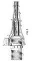
- the center conductor (2) of the dielectric coreis soldered or otherwise electrically bonded to the central conductor (50) of the end connectors (10) as shown in Figure 5 .
- This transition area, where the connector (10) connects to the cable,is then covered with a dielectric shrink tube(s) or wrapped with a dielectic tape material (52), such as PTFE and PE.
- This shrink tubemay be a double layer wrap as shown in Figure 5 (52, 52').
- the diameter of the dielectric shrink tube(s) or tape (52, 52') wrapped termination areashould be approximately the same thickness as the dielectric core (4).
- the laminate tape (18)is then electrically bonded to an integral or machined solderable ring (54) of the end connector (10) to provide stability of the electrical characteristics during flexure.
- the laminate tape (18)may be electrically connected to the solderable ringe (54) via a wire (56) which is soldered at one end to the solderable ring (54) and the other end to the laminate tape (18).
- laminate tape (18)may be directly electrically connected to the solder ring, as shown in Figure 5 .
- An outer conductor (6)is then wrapped over the inner tape (18), preferably in a longitudinally wrap, and electrically connected to the solderable ring (54).
- a jacket (8)is then used to cover the second conductor (6).
- the jacket (8)can be placed around the outer periphery of the second conductor (6) in a uniform thickness by heat shrink tubing, an extruder, or the like.
- a crimpable clamp (12)is then placed over the jacket (8) around the circumference of the solder ring (54).
- the ends of the cableare terminated with connectors (10) for establishing electrical connection to electrical devices or other cables.
- the flat part of the present inventionis most preferably used as a jumper cable that easily passes through small openings in a window sill or door jam due to its flat profile.
- This cableis most useful in connecting electrical devices inside a building to one outside or from one room to another room.
- the flat portion of the cableis short, preferably about 2-12 in (51-305 mm), more preferably about 5-8 in (127-203 mm), and most preferably about 6-7 in (152-178 mm).
Landscapes
- Insulated Conductors (AREA)
- Communication Cables (AREA)
- Manufacturing Of Electric Cables (AREA)
Description
- The present invention is generally related to coaxial cables and, in particular to coaxial cables with a flattened portion.
- Coaxial cables have long been used to provide a junction between electrical devices. Coaxial cables are usually composed of an elongated central conductor of metal containing a concentrically situated elongated outer tubular conductor of metal, both conductors being separated by a layer of an electrically insulating material. The central conductor may be composed of a single wire or multiple strands of wires.
- Coaxial cables are used in many areas such as transmission and computer cables, computer networking, video signal transmission, instrumentation cables, broadcast cables, e.g. TV companies between the community antenna and user homes or businesses, telephone companies, medical e.g. ultrasound devices, and lightweight coaxial cables for satellites. For some of these applications, connection of a device inside a building to another device outside the building or home is required. Because most coaxial cables are round, holes must be drilled in the building structure to pass the cable there through to connect the devices.
- Moreover, currently available coaxial cables may, in some cases, have deficiencies that limit their usefulness in the outdoor environment. For example, some cables will not sufficiently resist pulling forces and therefore may come apart when pulling forces are applied. Some cables also allow moisture to enter at one end and cause damage to the cable. In some cases, such moisture may also migrate through the cable to the inside of the structure and the components located therein. Additionally, the inventor has found that existing cables often do not provide sufficient electrical performance as well as electromagnetic and/or environmental isolation from the outside.
- Therefore, there remains a need for improvements in coaxial cable design, directed toward overcoming one or more of the above deficiencies.
US-A-4640569 discloses an adaptor for coupling a connector to a conductor of a flat, high-performance electrical cable having paired, parallel conductors.US-A-4488125 discloses a flat cable assembly in which a signal wire and at least one drain wire are embedded in a minor matrix of dielectric material.US-A-2006/0014425 discloses a co-axial cable compression connector which includes a connector body having a first end and a second end, and an internal passageway.- It is to be understood that both the following summary and the detailed description are exemplary and explanatory and are intended to provide further explanation of the invention as claimed. Neither the summary nor the description that follows is intended to define or limit the scope of the invention to the particular features mentioned in the summary or in the description.
- The present invention relates to a coaxial cable that has a flat portion, so that the cable can be used, for example, as a jumper cable that passes through a window sill, a door jam or under a rug. Because the cable is flat, it can easily pass through a space in the door jam or window sill without requiring holes to be drilled into the building structure or in any application where a flat cable jumper may be advantageous to the installed environment. In addition, through its design, the cable provides the electrical performance, the mechanical pull strength and environmental and electromagnetic isolation not available in current state-of-the-art products.
- In one embodiment, a central conductor is surrounded by a substantially flat dielectric, an inner laminate tape, a outer metal tape conductor, or an outer conductor consisting of braided, woven or wrapped metallic wires and an outer covering. The inner laminate tape with its bonding layer immediately adjacent to the dielectric core is folded over the underlying dielectric core in a manner to minimize thickness build-up and is preferably heat sealed to the dielectric core. The central conductor of the dielectric core is soldered, or otherwise electrically bonded or attached, to the central conductor of the end connectors. The transition area, where the conductor is attached to the end connector, is then covered with a dielectric shrink tube or wrapped with a dielectric tape material, such as polytetrafluoroethylene (PTFE) or polyethylene (PE). The diameter of the transition area should be approximately the same thickness as the dielectric core. The laminate tape is then electrically bonded to an integral or machined solderable ring part of the end connector to provide stability of the electrical characteristics during flexure. The outer metal tape conductor is sealed along its edges both radially and longitudinally. Each end of the cable preferably has a end connector that includes an integral solderable metallic ring or a separate machined, solderable, metallic ring. The outer metal tape conductor may then be soldered and sealed to the solderable ring. This soldering and sealing of the outer metal tape to the integral or machined metallic ring provides the mechanical pull strength and environmental and electromagnetic isolation not available in current state-of-the-art products.
- An adhesive or bonding material may be applied over the outer metal tape to bond the core to the outer jacket to improve the flexure performance of the jumper. A heat shrink tube may then be applied over the outer metal tape including the solderable ring. The heat shrink tubing may be, but is not limited to, PE, polyvinylchloride (PVC), polyvinylidene fluoride (PVDF), polyurethane (PU), PTFE, or other heat shrinkable or extrudeable jacket materials. Crimpable clamps may be used to further secure the jacket material to the core. On the outer jacket, an adhesive agent may be applied to allow for adhesion to surfaces where such an attribute is advantageous to the installation environment.
- In another embodiment of the invention, the cable includes an alternate type connector ("F", BNC, RCA, etc.) on at least one end of the cable and a direct connection to a device on the other end of the cable. The alternate type connector may be male or female and the cable may be flat for its entire length or flat for only a portion of its length with the remainder being round with a braided or other type of outer conductor that provides increased flexibility.
- In another embodiment of the invention, the cable is a short jumper cable connected on each end to other cables coming from each device. In this embodiment, the entire length of the cable is flat and having connectors on each end of the cable.
- In another embodiment, the cable is of sufficent length such that the cable directly connects the external and internal devices. In this embodiment, the cable is flat for the entire length and has connectors on both ends.
- In another embodiment, the cable includes connectors on each end such that the cable connects directly to both devices but only the portion of the cable that passes under the window sill or door jam is flat and the rest of the cable is substantially round, with a braided, served or other type of outer conductor that provides increased flexibility.
- The features and advantages of the invention will be made apparent by the written description, the claims, and the accompanying drawings or may be learned by practicing the invention.
- Many aspects of the invention can be better understood with reference to the following drawings. The components in the drawings are not necessarily to scale, emphasis instead being placed upon clearly illustrating the principles of the present invention. Moreover, in the drawings like reference numerals designate corresponding parts throughout the several views:
Figure 1 shows a plan view of the cable;Figure 2 shows a cross section of the cable at plane A-A; andFigure 3 shows the cable with the layers pealed off.Figure 4 shows the cross sectional view of the die for extruding the flat dielectric.Figure 5 shows a cross section of the cable along the longitudinal direction at the transition area.- This disclosure provides and discloses exemplary embodiments. In particular, the specification discloses one or more embodiments that incorporate the features of the invention. The embodiment(s) described, and references in the specification to "one embodiment", "an embodiment", "an example embodiment", etc., indicate that the embodiment(s) described may include a particular feature, structure, or characteristic, but every embodiment may not necessarily include the particular feature, structure, or characteristic. Moreover, such phrases are not necessarily referring to the same embodiment. Further, when a particular feature, structure, or characteristic is described in connection with an embodiment, persons skilled in the art may effect such feature, structure, or characteristic in connection with other embodiments whether or not explicitly described.
Figure 1 shows an embodiment of the present invention. The cable (100) generally contains two ends and a middle portion (16). The ends are preferably terminated with connectors (10) (male or female) to allow for electrical connection of the cable (100) to an electrical device(s). At least a part of the middle portion (16) is substantially flat. "Substantially flat" as used herein refers to the fact that the cable has a relatively broad surface in relation to its thickness. The flat portion of the cable can be the entire length of the cable (except the ends where connectors and/or electrical devices are attached) or a portion of the cable.Figure 2 shows a cross-sectional view of the cable at the A-A plane. The cable contains several successive layers. The center conductor (2) is located at the core of the cable. While copper, copper-clad aluminum, or copper-clad steel conductor is preferred for the center conductor (2), any type of conductive alloy, solid, hollow, stranded, corrugated or clad will suffice.- Covering the center conductor (2) is a dielectric (4). The dielectric (4) is substantially flat, and preferably, tapers to a point on its lateral sides. The flatness of the dielectric is such that the ratio of the width (w) to the height (h) is in the range of 3:1 to 10:1. Furthermore the height (h) to center conductor diameter ratio is in the range of 4:1 to 6:1. The dielectric can be, but is not limited to taped, solid or foamed polyolefins and fluropolymers.
- The dielectric (4) is preferably covered by a bondable, inner tape (18). In a prefered embodiment, the inner tape (18) is formed from copper tape with an adhesive bonding layer, aluminum/polyester/aluminum tape with an adhesive bonding layer, aluminum/polypropylene/aluminum with an adhesive bonding layer, or similar aluminum or bi-mettalic (copper clad aluminum, etc.) tapes having an adhesive bonding layer. In any case, the adhesive bonding layer is facing inward and immediately adjacent to the dielectric core. The tape (18) is longitudinally wrapped such that the edges of the inner laminate tape overlap each other along the longitudinal direction of the cable (100) so that the build-up-over the dielectric (4) is preferably equal to no more than two times the tape (18) thickness. The bonding agent on the tape can then activated using heat, ultraviolet (UV) light, or other means.
- The central conductor of the dielectric core is soldered or otherwise electrically bonded to the central conductor of the end connectors (10). This transition area is then covered with a dielectric shrink tube or wrapped with a dielectic tape material (52), such as polytetrafluoroethylene (PTFE) or polyethylene (PE). The diameter of the dielectric shrink tube or tape wrapped termination area should be approximately the same thickness as the dielectric core.
- The metallic portion of the inner tape (18) may be electrically bonded, using a small diameter jumper wire or other means, to the end connectors (10) at the integral or machined solderable ring. Alternatively, the metallic portion of the inner tape (18) may be directly electrically bonded to the end connector at the solderable ring (54).
- The inner tape (18) is preferably covered by an outer conductor (6) before a jacket (8) is applied thereon. In a preferred embodiment, the outer conductor (6) is formed from aluminum, copper, bimettalics or the like. Preferably, the outer conductor (6) is a copper, aluminum or bimettalic tape that is longitudinally wrapped such that the edges of the outer conductor (6) overlap each other along the longitudinal direction of the cable (100) and in a region away from the area of maximum thickness, as shown in
Figure 3 . In a preferred embodiment, the edges of the outer conductor (6) are soldered together, resulting in a solder line (20) that parallels the longitudinal direction of the cable (100). In this case, the edges can abut and be soldered together, or can overlap and be soldered together. Either way, the process results in the solder line (20) as shown inFigure 3 . - A bonding agent may be applied to the outer surface of the outer conductor or to the inner surface of the jacket to bond the layers together and improve the mechanical performance of the construction in high moisture environments, during flexure, etc.
- The jacket (8) can be formed from a variety of non-conductive or semiconductive compounds typically used to jacket cables. Preferably, a white polyethylene (PE) jacket, which provides both ultraviolet protection and good handling characteristics, is used. As is known to those skilled in the art, the jacket can also be formed from PVC, TEFLON®, PVDF or Kynar®, PU, and other compounds. The jacket may also be colored, color coded and/or printed or striped to identify the cable.
- Preferrably, the connection between the connectors and the cable are sealed to prevent moisture from entering the cable. This can be accomplished by sealing the jacket (8) to the connector (10) with a crimpable clamp (12) or injection molded boot. Further, the outer conductor can also be soldered onto the connector at its circumference to seal the dielectric and the inner conductor. Other methods of sealing, including, but not limited to, glue, silicone sealant, flooding compounds, ultrasonic welding, and the like are also appropriate for the present invention.
- The cable of the present invention is made by extruding a substantially flat dielectric (4) over the center conductor (2), preferably using an extrusion die depicted in
Figure 4 . The die (40) is generally triangular having a height (h) and the legs sloping downward to the base. The corners (42, 44, 46) of the die (40) are preferably rounded to eliminate sharp edges. The center conductor (2) locates at the center of the die (40). The flatness of the dielectric (4) is such that the ratio of the width (w) to the height (h) is in the range of 3:1 to 10:1, preferably 5:1 to 9:1, and most preferably 7:1 to 9:1. An inner laminate tape (18) is folded over the underlying dielectric core in a manner to minimize thickness build-up and heat sealed to the dielectric core. The center conductor (2) of the dielectric core is soldered or otherwise electrically bonded to the central conductor (50) of the end connectors (10) as shown inFigure 5 . This transition area, where the connector (10) connects to the cable, is then covered with a dielectric shrink tube(s) or wrapped with a dielectic tape material (52), such as PTFE and PE. This shrink tube may be a double layer wrap as shown inFigure 5 (52, 52'). The diameter of the dielectric shrink tube(s) or tape (52, 52') wrapped termination area should be approximately the same thickness as the dielectric core (4). The laminate tape (18) is then electrically bonded to an integral or machined solderable ring (54) of the end connector (10) to provide stability of the electrical characteristics during flexure. In one embodiment, the laminate tape (18) may be electrically connected to the solderable ringe (54) via a wire (56) which is soldered at one end to the solderable ring (54) and the other end to the laminate tape (18). Alternatively, laminate tape (18) may be directly electrically connected to the solder ring, as shown inFigure 5 . - An outer conductor (6) is then wrapped over the inner tape (18), preferably in a longitudinally wrap, and electrically connected to the solderable ring (54). A jacket (8) is then used to cover the second conductor (6). In a preferred embodiment, the jacket (8) can be placed around the outer periphery of the second conductor (6) in a uniform thickness by heat shrink tubing, an extruder, or the like. A crimpable clamp (12) is then placed over the jacket (8) around the circumference of the solder ring (54). In a preferred embodiment, the ends of the cable are terminated with connectors (10) for establishing electrical connection to electrical devices or other cables.
- The flat part of the present invention is most preferably used as a jumper cable that easily passes through small openings in a window sill or door jam due to its flat profile. This cable is most useful in connecting electrical devices inside a building to one outside or from one room to another room. Generally, the flat portion of the cable (is short, preferably about 2-12 in (51-305 mm), more preferably about 5-8 in (127-203 mm), and most preferably about 6-7 in (152-178 mm).
- While various embodiments of the present invention have been described above, it should be understood that they have been presented by way of example only, and not limitation. Thus, the breadth and scope of the present invention should not be limited by any of the above-described exemplary embodiments, but should be defined only in accordance with the following claims and their equivalents.
Claims (17)
- A coaxial cable, comprising:a center conductor (2) concentrically surrounded by a dielectric (4), such that at least a portion of the dielectric (4) is a flat or flattened portion, having a broader surface in relation to its thickness;an outer conductor (6) surrounding at least the dielectric (4);a jacket (8) covering the outer conductor (6);characterised in that it comprisesfirst and second connectors (10) connected to respective ends of the cable (100),wherein the cable (100) connects to each connector (10) by electrically connecting the center conductor (2) with a center conductor (50) of the connector (10) and electrically connecting the outer conductor (6) to a ring (54) on the connector (10) by directly connecting the outer conductor (6) to the ring (54) or by connecting the outer conductor (6) to the ring (54) via a wire (56).
- The coaxial cable of claim 1, further comprising first and second ring clamps (12) attached to respective connectors (10) to seal the jacket (8) to the connector (10).
- The coaxial cable of claim 1, wherein the outer conductor (6) is sealed circumferentially and longitudinally.
- The coaxial cable of claim 1 or 2, wherein the outer conductor (6) is a metal tape.
- The coaxial cable of claim 4, wherein the metal is copper or aluminum.
- The coaxial cable of any of claims 1 to 5, wherein the outer conductor (6) is longitudinally wrapped around the dielectric (4).
- The coaxial cable of any of claims 1 to 6, wherein the center conductor (2) is copper, copper-clad aluminum, or copper-clad steel.
- The coaxial cable of claim 1, wherein a transition area where the connector (10) connects to the cable (100) is wrapped with a dielectric tape (52) or a heat shrink polymer.
- The coaxial cable of claim 8, wherein the transition area is approximately equal in impedance to the adjacent dielectric core and connector (10).
- A method for making a coaxial cable, comprising the steps of:providing a center conductor (2);surrounding the center conductor (2) with a dielectric (4), wherein at least a portion of the dielectric (4) is a flat or flattened portion, having a broader surface in relation to its thickness;surrounding the dielectric (4) with an outer conductor (6);surrounding the outer conductor (6) with a jacket (8);characterised by the step of providing a connector (10) at each end of the cable (100), wherein the cable (100) connects to each connector (10) by electrically connecting the center conductor (2) with a center conductor (50) of the connector (10) and electrically connecting the outer conductor (6) to a ring (54) on the connector (10) by directly connecting the outer conductor (6) to the ring (54) or by connecting the outer conductor (6) to the ring (54) via a wire (56).
- The method of claim 10, further comprising the step of:attaching a ring clamp (12) to each connector (10) to seal the jacket (8) to the connector (10).
- The method of claim 10, wherein the outer conductor (6) is sealed circumferentially and longitudinally.
- The method of claims 10 to 12, wherein the outer conductor (6) is a metal tape.
- The method of claim 13, wherein the metal is copper or aluminum.
- The method of claims 10 to 14, wherein the outer conductor (6) is longitudinally wrapped around the dielectric (4).
- The method of claims 10 to 15, wherein the center conductor (2) is copper, copper-clad aluminum, or copper-clad steel.
- A method for connecting two electrical devices, comprising the steps of
providing a first electrical device;
providing a second electrical device;characterised by the step of
providing a co-axial cable (100) according to any of claims 1 to 9; and
electrically connecting the first and second electrical devices with the co-axial cable (100).
Applications Claiming Priority (2)
| Application Number | Priority Date | Filing Date | Title |
|---|---|---|---|
| US11/350,861US7314998B2 (en) | 2006-02-10 | 2006-02-10 | Coaxial cable jumper device |
| PCT/US2007/003790WO2007095232A2 (en) | 2006-02-10 | 2007-02-12 | Coaxial cable jumper device |
Publications (3)
| Publication Number | Publication Date |
|---|---|
| EP2002450A2 EP2002450A2 (en) | 2008-12-17 |
| EP2002450A4 EP2002450A4 (en) | 2012-03-14 |
| EP2002450B1true EP2002450B1 (en) | 2014-08-06 |
Family
ID=38367173
Family Applications (1)
| Application Number | Title | Priority Date | Filing Date |
|---|---|---|---|
| EP07750617.8ANot-in-forceEP2002450B1 (en) | 2006-02-10 | 2007-02-12 | Coaxial cable jumper device |
Country Status (8)
| Country | Link |
|---|---|
| US (1) | US7314998B2 (en) |
| EP (1) | EP2002450B1 (en) |
| JP (1) | JP2009526371A (en) |
| KR (1) | KR101330629B1 (en) |
| CN (1) | CN101401170B (en) |
| CA (1) | CA2642459A1 (en) |
| MX (1) | MX2008010288A (en) |
| WO (1) | WO2007095232A2 (en) |
Families Citing this family (35)
| Publication number | Priority date | Publication date | Assignee | Title |
|---|---|---|---|---|
| GB2459454A (en)* | 2008-04-22 | 2009-10-28 | Tyco Electronics | Power Cable |
| JP5261286B2 (en)* | 2009-05-22 | 2013-08-14 | 株式会社フジクラ | Planar coaxial cable terminal structure |
| US20110011638A1 (en)* | 2009-07-16 | 2011-01-20 | Paul Gemme | Shielding tape with edge indicator |
| US9728304B2 (en)* | 2009-07-16 | 2017-08-08 | Pct International, Inc. | Shielding tape with multiple foil layers |
| US20110021069A1 (en)* | 2009-07-21 | 2011-01-27 | Yiping Hu | Thin format crush resistant electrical cable |
| US12249440B2 (en)* | 2009-12-09 | 2025-03-11 | Holland Electronics, Llc | Guarded coaxial cable assembly |
| US9053837B2 (en) | 2009-12-09 | 2015-06-09 | Holland Electronics, Llc | Protected coaxial cable |
| US10573433B2 (en) | 2009-12-09 | 2020-02-25 | Holland Electronics, Llc | Guarded coaxial cable assembly |
| US8308505B2 (en)* | 2009-12-09 | 2012-11-13 | Scott Hatton | Guarded coaxial cable assembly |
| US8692116B2 (en)* | 2009-12-09 | 2014-04-08 | Holland Electronics, Llc | Protected coaxial cable |
| WO2011146911A1 (en) | 2010-05-21 | 2011-11-24 | Pct International, Inc. | Connector with locking mechanism and associated systems and methods |
| US8604343B2 (en) | 2010-06-17 | 2013-12-10 | Karen Nixon-Lane | Window compatible electrical power device |
| US8579658B2 (en) | 2010-08-20 | 2013-11-12 | Timothy L. Youtsey | Coaxial cable connectors with washers for preventing separation of mated connectors |
| USD710800S1 (en)* | 2011-05-26 | 2014-08-12 | Willis Electric Co., Ltd. | Cylindrical transformer |
| US9028276B2 (en) | 2011-12-06 | 2015-05-12 | Pct International, Inc. | Coaxial cable continuity device |
| US8766095B2 (en)* | 2011-12-12 | 2014-07-01 | Unison Industries, Llc | Ignition lead |
| US8858250B2 (en) | 2012-09-19 | 2014-10-14 | International Business Machines Corporation | Electrical cable assembly |
| US9039450B2 (en)* | 2013-01-15 | 2015-05-26 | Delphi Technologies, Inc. | Termination arrangement for a cable bundle |
| US20150118897A1 (en)* | 2013-10-24 | 2015-04-30 | Andrew Llc | Coaxial cable and connector with capacitive coupling |
| US9608343B2 (en) | 2013-10-24 | 2017-03-28 | Commscope Technologies Llc | Coaxial cable and connector with capacitive coupling |
| TW201517703A (en)* | 2013-10-30 | 2015-05-01 | Adv Flexible Circuits Co Ltd | Side-rim waterproof structure of flexible printed circuit board |
| WO2016010885A1 (en)* | 2014-07-15 | 2016-01-21 | Commscope Technologies Llc | Coaxial cable and connector with tuned capacitive coupling |
| WO2016179606A1 (en)* | 2015-05-07 | 2016-11-10 | Wilson Electronics, Llc | Flat coaxial cable |
| CN106450988B (en)* | 2015-08-06 | 2020-03-31 | 富士康(昆山)电脑接插件有限公司 | Cable connector assembly and manufacturing method thereof |
| CN205984340U (en)* | 2016-01-22 | 2017-02-22 | 3M创新有限公司 | Flat electric cable and cable subassembly |
| US10283238B1 (en) | 2018-03-19 | 2019-05-07 | Te Connectivity Corporation | Electrical cable |
| US10304592B1 (en) | 2018-03-19 | 2019-05-28 | Te Connectivity Corporation | Electrical cable |
| US10283240B1 (en) | 2018-03-19 | 2019-05-07 | Te Connectivity Corporation | Electrical cable |
| US11069458B2 (en)* | 2018-04-13 | 2021-07-20 | TE Connectivity Services Gmbh | Electrical cable |
| US10741308B2 (en) | 2018-05-10 | 2020-08-11 | Te Connectivity Corporation | Electrical cable |
| US10600537B1 (en) | 2018-10-12 | 2020-03-24 | Te Connectivity Corporation | Electrical cable |
| US12087465B2 (en) | 2018-10-12 | 2024-09-10 | Te Connectivity Solutions Gmbh | Electrical cable |
| US10600536B1 (en) | 2018-10-12 | 2020-03-24 | Te Connectivity Corporation | Electrical cable |
| US10950367B1 (en) | 2019-09-05 | 2021-03-16 | Te Connectivity Corporation | Electrical cable |
| CN115249936B (en)* | 2022-09-22 | 2022-12-20 | 中国科学院合肥物质科学研究院 | Coaxial jumper type superconducting cable joint structure and manufacturing method thereof |
Family Cites Families (25)
| Publication number | Priority date | Publication date | Assignee | Title |
|---|---|---|---|---|
| US3296365A (en)* | 1964-04-03 | 1967-01-03 | Thomas & Betts Co Inc | Flat conductor cable jumper |
| JPS5238717Y2 (en)* | 1972-03-10 | 1977-09-02 | ||
| US3878341A (en)* | 1973-10-11 | 1975-04-15 | Western Electric Co | Interstage linkage for switching network |
| JPS535195Y2 (en)* | 1973-11-02 | 1978-02-08 | ||
| US4488125A (en)* | 1982-07-06 | 1984-12-11 | Brand-Rex Company | Coaxial cable structures and methods for manufacturing the same |
| US4508415A (en)* | 1983-07-29 | 1985-04-02 | Amp Incorporated | Shielded electrical connector for flat cable |
| US4640569A (en)* | 1985-03-27 | 1987-02-03 | Amp Incorporated | Adaptor for coupling a cable to a connector |
| US4664464A (en)* | 1985-04-09 | 1987-05-12 | Allied Corporation | Coaxial cable termination |
| US4801764A (en)* | 1986-02-11 | 1989-01-31 | Cooper Industries, Inc. | Cable assembly for use under carpeting |
| JPS63164116U (en)* | 1987-04-14 | 1988-10-26 | ||
| US4772212A (en)* | 1987-05-20 | 1988-09-20 | Amp Incorporated | Electrical connector for shielded cables with shielded conductor pairs |
| FR2640819B1 (en)* | 1988-12-20 | 1991-05-31 | Thomson Csf | SEMI-RIGID CABLE FOR THE TRANSMISSION OF MICROWAVE WAVES |
| JPH0533413U (en)* | 1991-10-07 | 1993-04-30 | 日本電気株式会社 | coaxial cable |
| US5259792A (en)* | 1992-05-26 | 1993-11-09 | Woven Electronics | Electrical connector housing and method for minimizing EMI emissions |
| US5349133A (en)* | 1992-10-19 | 1994-09-20 | Electronic Development, Inc. | Magnetic and electric field shield |
| US5460544A (en)* | 1993-05-26 | 1995-10-24 | Yazaki Corporation | Electro-magnetically shielded connector |
| US5965847A (en)* | 1996-11-12 | 1999-10-12 | Sumitomo Wiring Systems, Ltd. | Shield connector |
| US6464516B2 (en)* | 1997-09-29 | 2002-10-15 | George M. Baldock | Wiring interconnection system |
| US6646207B1 (en)* | 2000-05-12 | 2003-11-11 | Thomson Licensing S. A. | Double helix lead dressing of flat flexible cables |
| US6384337B1 (en)* | 2000-06-23 | 2002-05-07 | Commscope Properties, Llc | Shielded coaxial cable and method of making same |
| JP3928770B2 (en)* | 2001-01-17 | 2007-06-13 | 矢崎総業株式会社 | Terminal processing structure of shielded wire |
| US6545223B2 (en)* | 2001-08-22 | 2003-04-08 | George M. Baldock | Cable |
| US6716062B1 (en)* | 2002-10-21 | 2004-04-06 | John Mezzalingua Associates, Inc. | Coaxial cable F connector with improved RFI sealing |
| JP2005310528A (en)* | 2004-04-21 | 2005-11-04 | Fujikura Ltd | Micro coaxial cable |
| US7029326B2 (en)* | 2004-07-16 | 2006-04-18 | John Mezzalingua Associates, Inc. | Compression connector for coaxial cable |
- 2006
- 2006-02-10USUS11/350,861patent/US7314998B2/enactiveActive
- 2007
- 2007-02-12KRKR1020087022038Apatent/KR101330629B1/ennot_activeExpired - Fee Related
- 2007-02-12CNCN2007800086763Apatent/CN101401170B/ennot_activeExpired - Fee Related
- 2007-02-12CACA002642459Apatent/CA2642459A1/ennot_activeAbandoned
- 2007-02-12EPEP07750617.8Apatent/EP2002450B1/ennot_activeNot-in-force
- 2007-02-12JPJP2008554426Apatent/JP2009526371A/enactivePending
- 2007-02-12MXMX2008010288Apatent/MX2008010288A/enactiveIP Right Grant
- 2007-02-12WOPCT/US2007/003790patent/WO2007095232A2/enactiveApplication Filing
Also Published As
| Publication number | Publication date |
|---|---|
| KR20080091862A (en) | 2008-10-14 |
| JP2009526371A (en) | 2009-07-16 |
| KR101330629B1 (en) | 2013-11-22 |
| CN101401170A (en) | 2009-04-01 |
| WO2007095232A2 (en) | 2007-08-23 |
| WO2007095232A3 (en) | 2008-09-12 |
| HK1127958A1 (en) | 2009-10-09 |
| CA2642459A1 (en) | 2007-08-23 |
| US20070187133A1 (en) | 2007-08-16 |
| CN101401170B (en) | 2012-07-18 |
| MX2008010288A (en) | 2008-11-27 |
| EP2002450A4 (en) | 2012-03-14 |
| EP2002450A2 (en) | 2008-12-17 |
| US7314998B2 (en) | 2008-01-01 |
Similar Documents
| Publication | Publication Date | Title |
|---|---|---|
| EP2002450B1 (en) | Coaxial cable jumper device | |
| US5521331A (en) | Shielded electric cable | |
| US6624359B2 (en) | Multifolded composite tape for use in cable manufacture and methods for making same | |
| US8246390B2 (en) | Integral bonding attachment | |
| CN101341632B (en) | Integral connecting device | |
| US6677535B2 (en) | Electrical cable | |
| US20100276179A1 (en) | Multilayer cable jacket | |
| KR20150018335A (en) | Hdmi cable, hdmi connector and hdmi interface for high definition video/audio playback devices | |
| US5321202A (en) | Shielded electric cable | |
| EP3713024B1 (en) | Wire joint and manufacturing method thereof | |
| JP2002117731A (en) | Flat cable for lan | |
| JP2000082346A (en) | Shield tape and shield wire using the same | |
| US20120103658A1 (en) | Coaxial cable center conductor having multiple precoat layers | |
| HK1127958B (en) | Coaxial cable jumper device | |
| CN112309617A (en) | Flexible flat cable, its manufacturing method and signal transmission device | |
| JP7701909B2 (en) | Coaxial Flat Cable | |
| CN213183661U (en) | High-voltage coaxial shielding wire cable | |
| CN216751170U (en) | Cable intermediate head | |
| JPH01195608A (en) | Shielded flat cable, flat cable for shielded flat cable and manufacture thereof | |
| TW202429488A (en) | Cable | |
| KR20240072988A (en) | coax | |
| JP2000323201A (en) | Waterproofing structure of shield wire end portion | |
| CN111430952A (en) | Longitudinally-wrapped aluminum-plastic composite tape joint for waterproof cable and manufacturing method thereof | |
| JP2001076551A (en) | Shielded cable | |
| JP2004178869A (en) | Connection method and connection part of laminate tape for cable |
Legal Events
| Date | Code | Title | Description |
|---|---|---|---|
| PUAI | Public reference made under article 153(3) epc to a published international application that has entered the european phase | Free format text:ORIGINAL CODE: 0009012 | |
| 17P | Request for examination filed | Effective date:20080910 | |
| AK | Designated contracting states | Kind code of ref document:A2 Designated state(s):AT BE BG CH CY CZ DE DK EE ES FI FR GB GR HU IE IS IT LI LT LU LV MC NL PL PT RO SE SI SK TR | |
| AX | Request for extension of the european patent | Extension state:AL BA HR MK RS | |
| REG | Reference to a national code | Ref country code:HK Ref legal event code:DE Ref document number:1127958 Country of ref document:HK | |
| A4 | Supplementary search report drawn up and despatched | Effective date:20120214 | |
| RIC1 | Information provided on ipc code assigned before grant | Ipc:H01B 11/18 20060101ALI20120208BHEP Ipc:H01B 11/06 20060101AFI20120208BHEP | |
| DAX | Request for extension of the european patent (deleted) | ||
| GRAP | Despatch of communication of intention to grant a patent | Free format text:ORIGINAL CODE: EPIDOSNIGR1 | |
| INTG | Intention to grant announced | Effective date:20140224 | |
| GRAS | Grant fee paid | Free format text:ORIGINAL CODE: EPIDOSNIGR3 | |
| GRAA | (expected) grant | Free format text:ORIGINAL CODE: 0009210 | |
| AK | Designated contracting states | Kind code of ref document:B1 Designated state(s):AT BE BG CH CY CZ DE DK EE ES FI FR GB GR HU IE IS IT LI LT LU LV MC NL PL PT RO SE SI SK TR | |
| REG | Reference to a national code | Ref country code:GB Ref legal event code:FG4D | |
| REG | Reference to a national code | Ref country code:AT Ref legal event code:REF Ref document number:681359 Country of ref document:AT Kind code of ref document:T Effective date:20140815 Ref country code:CH Ref legal event code:EP | |
| REG | Reference to a national code | Ref country code:IE Ref legal event code:FG4D | |
| REG | Reference to a national code | Ref country code:DE Ref legal event code:R096 Ref document number:602007037986 Country of ref document:DE Effective date:20140918 | |
| REG | Reference to a national code | Ref country code:AT Ref legal event code:MK05 Ref document number:681359 Country of ref document:AT Kind code of ref document:T Effective date:20140806 | |
| REG | Reference to a national code | Ref country code:NL Ref legal event code:VDEP Effective date:20140806 | |
| REG | Reference to a national code | Ref country code:LT Ref legal event code:MG4D | |
| PG25 | Lapsed in a contracting state [announced via postgrant information from national office to epo] | Ref country code:GR Free format text:LAPSE BECAUSE OF FAILURE TO SUBMIT A TRANSLATION OF THE DESCRIPTION OR TO PAY THE FEE WITHIN THE PRESCRIBED TIME-LIMIT Effective date:20141107 Ref country code:BG Free format text:LAPSE BECAUSE OF FAILURE TO SUBMIT A TRANSLATION OF THE DESCRIPTION OR TO PAY THE FEE WITHIN THE PRESCRIBED TIME-LIMIT Effective date:20141106 Ref country code:FI Free format text:LAPSE BECAUSE OF FAILURE TO SUBMIT A TRANSLATION OF THE DESCRIPTION OR TO PAY THE FEE WITHIN THE PRESCRIBED TIME-LIMIT Effective date:20140806 Ref country code:LT Free format text:LAPSE BECAUSE OF FAILURE TO SUBMIT A TRANSLATION OF THE DESCRIPTION OR TO PAY THE FEE WITHIN THE PRESCRIBED TIME-LIMIT Effective date:20140806 Ref country code:PT Free format text:LAPSE BECAUSE OF FAILURE TO SUBMIT A TRANSLATION OF THE DESCRIPTION OR TO PAY THE FEE WITHIN THE PRESCRIBED TIME-LIMIT Effective date:20141209 Ref country code:SE Free format text:LAPSE BECAUSE OF FAILURE TO SUBMIT A TRANSLATION OF THE DESCRIPTION OR TO PAY THE FEE WITHIN THE PRESCRIBED TIME-LIMIT Effective date:20140806 Ref country code:ES Free format text:LAPSE BECAUSE OF FAILURE TO SUBMIT A TRANSLATION OF THE DESCRIPTION OR TO PAY THE FEE WITHIN THE PRESCRIBED TIME-LIMIT Effective date:20140806 | |
| PG25 | Lapsed in a contracting state [announced via postgrant information from national office to epo] | Ref country code:CY Free format text:LAPSE BECAUSE OF FAILURE TO SUBMIT A TRANSLATION OF THE DESCRIPTION OR TO PAY THE FEE WITHIN THE PRESCRIBED TIME-LIMIT Effective date:20140806 Ref country code:LV Free format text:LAPSE BECAUSE OF FAILURE TO SUBMIT A TRANSLATION OF THE DESCRIPTION OR TO PAY THE FEE WITHIN THE PRESCRIBED TIME-LIMIT Effective date:20140806 Ref country code:PL Free format text:LAPSE BECAUSE OF FAILURE TO SUBMIT A TRANSLATION OF THE DESCRIPTION OR TO PAY THE FEE WITHIN THE PRESCRIBED TIME-LIMIT Effective date:20140806 Ref country code:NL Free format text:LAPSE BECAUSE OF FAILURE TO SUBMIT A TRANSLATION OF THE DESCRIPTION OR TO PAY THE FEE WITHIN THE PRESCRIBED TIME-LIMIT Effective date:20140806 Ref country code:IS Free format text:LAPSE BECAUSE OF FAILURE TO SUBMIT A TRANSLATION OF THE DESCRIPTION OR TO PAY THE FEE WITHIN THE PRESCRIBED TIME-LIMIT Effective date:20141206 Ref country code:AT Free format text:LAPSE BECAUSE OF FAILURE TO SUBMIT A TRANSLATION OF THE DESCRIPTION OR TO PAY THE FEE WITHIN THE PRESCRIBED TIME-LIMIT Effective date:20140806 | |
| PG25 | Lapsed in a contracting state [announced via postgrant information from national office to epo] | Ref country code:EE Free format text:LAPSE BECAUSE OF FAILURE TO SUBMIT A TRANSLATION OF THE DESCRIPTION OR TO PAY THE FEE WITHIN THE PRESCRIBED TIME-LIMIT Effective date:20140806 Ref country code:DK Free format text:LAPSE BECAUSE OF FAILURE TO SUBMIT A TRANSLATION OF THE DESCRIPTION OR TO PAY THE FEE WITHIN THE PRESCRIBED TIME-LIMIT Effective date:20140806 Ref country code:CZ Free format text:LAPSE BECAUSE OF FAILURE TO SUBMIT A TRANSLATION OF THE DESCRIPTION OR TO PAY THE FEE WITHIN THE PRESCRIBED TIME-LIMIT Effective date:20140806 Ref country code:RO Free format text:LAPSE BECAUSE OF FAILURE TO SUBMIT A TRANSLATION OF THE DESCRIPTION OR TO PAY THE FEE WITHIN THE PRESCRIBED TIME-LIMIT Effective date:20140806 Ref country code:SK Free format text:LAPSE BECAUSE OF FAILURE TO SUBMIT A TRANSLATION OF THE DESCRIPTION OR TO PAY THE FEE WITHIN THE PRESCRIBED TIME-LIMIT Effective date:20140806 Ref country code:IT Free format text:LAPSE BECAUSE OF FAILURE TO SUBMIT A TRANSLATION OF THE DESCRIPTION OR TO PAY THE FEE WITHIN THE PRESCRIBED TIME-LIMIT Effective date:20140806 | |
| REG | Reference to a national code | Ref country code:DE Ref legal event code:R097 Ref document number:602007037986 Country of ref document:DE | |
| PLBE | No opposition filed within time limit | Free format text:ORIGINAL CODE: 0009261 | |
| STAA | Information on the status of an ep patent application or granted ep patent | Free format text:STATUS: NO OPPOSITION FILED WITHIN TIME LIMIT | |
| PG25 | Lapsed in a contracting state [announced via postgrant information from national office to epo] | Ref country code:BE Free format text:LAPSE BECAUSE OF NON-PAYMENT OF DUE FEES Effective date:20150228 | |
| 26N | No opposition filed | Effective date:20150507 | |
| REG | Reference to a national code | Ref country code:HK Ref legal event code:GR Ref document number:1127958 Country of ref document:HK | |
| REG | Reference to a national code | Ref country code:DE Ref legal event code:R119 Ref document number:602007037986 Country of ref document:DE | |
| PG25 | Lapsed in a contracting state [announced via postgrant information from national office to epo] | Ref country code:LU Free format text:LAPSE BECAUSE OF FAILURE TO SUBMIT A TRANSLATION OF THE DESCRIPTION OR TO PAY THE FEE WITHIN THE PRESCRIBED TIME-LIMIT Effective date:20150212 | |
| REG | Reference to a national code | Ref country code:CH Ref legal event code:PL | |
| PG25 | Lapsed in a contracting state [announced via postgrant information from national office to epo] | Ref country code:CH Free format text:LAPSE BECAUSE OF NON-PAYMENT OF DUE FEES Effective date:20150228 Ref country code:LI Free format text:LAPSE BECAUSE OF NON-PAYMENT OF DUE FEES Effective date:20150228 Ref country code:MC Free format text:LAPSE BECAUSE OF FAILURE TO SUBMIT A TRANSLATION OF THE DESCRIPTION OR TO PAY THE FEE WITHIN THE PRESCRIBED TIME-LIMIT Effective date:20140806 | |
| REG | Reference to a national code | Ref country code:IE Ref legal event code:MM4A | |
| REG | Reference to a national code | Ref country code:FR Ref legal event code:ST Effective date:20151030 | |
| PG25 | Lapsed in a contracting state [announced via postgrant information from national office to epo] | Ref country code:SI Free format text:LAPSE BECAUSE OF FAILURE TO SUBMIT A TRANSLATION OF THE DESCRIPTION OR TO PAY THE FEE WITHIN THE PRESCRIBED TIME-LIMIT Effective date:20140806 | |
| PG25 | Lapsed in a contracting state [announced via postgrant information from national office to epo] | Ref country code:IE Free format text:LAPSE BECAUSE OF NON-PAYMENT OF DUE FEES Effective date:20150212 Ref country code:DE Free format text:LAPSE BECAUSE OF NON-PAYMENT OF DUE FEES Effective date:20150901 | |
| PG25 | Lapsed in a contracting state [announced via postgrant information from national office to epo] | Ref country code:FR Free format text:LAPSE BECAUSE OF NON-PAYMENT OF DUE FEES Effective date:20150302 | |
| PGFP | Annual fee paid to national office [announced via postgrant information from national office to epo] | Ref country code:GB Payment date:20160127 Year of fee payment:10 | |
| PG25 | Lapsed in a contracting state [announced via postgrant information from national office to epo] | Ref country code:BE Free format text:LAPSE BECAUSE OF FAILURE TO SUBMIT A TRANSLATION OF THE DESCRIPTION OR TO PAY THE FEE WITHIN THE PRESCRIBED TIME-LIMIT Effective date:20140806 | |
| PG25 | Lapsed in a contracting state [announced via postgrant information from national office to epo] | Ref country code:HU Free format text:LAPSE BECAUSE OF FAILURE TO SUBMIT A TRANSLATION OF THE DESCRIPTION OR TO PAY THE FEE WITHIN THE PRESCRIBED TIME-LIMIT; INVALID AB INITIO Effective date:20070212 | |
| PG25 | Lapsed in a contracting state [announced via postgrant information from national office to epo] | Ref country code:TR Free format text:LAPSE BECAUSE OF FAILURE TO SUBMIT A TRANSLATION OF THE DESCRIPTION OR TO PAY THE FEE WITHIN THE PRESCRIBED TIME-LIMIT Effective date:20140806 | |
| GBPC | Gb: european patent ceased through non-payment of renewal fee | Effective date:20170212 | |
| PG25 | Lapsed in a contracting state [announced via postgrant information from national office to epo] | Ref country code:GB Free format text:LAPSE BECAUSE OF NON-PAYMENT OF DUE FEES Effective date:20170212 |