EP2002415B1 - Warning apparatus and method - Google Patents
Warning apparatus and methodDownload PDFInfo
- Publication number
- EP2002415B1 EP2002415B1EP07732207.1AEP07732207AEP2002415B1EP 2002415 B1EP2002415 B1EP 2002415B1EP 07732207 AEP07732207 AEP 07732207AEP 2002415 B1EP2002415 B1EP 2002415B1
- Authority
- EP
- European Patent Office
- Prior art keywords
- vehicle
- alert
- pedestrian
- hazard
- warning
- Prior art date
- Legal status (The legal status is an assumption and is not a legal conclusion. Google has not performed a legal analysis and makes no representation as to the accuracy of the status listed.)
- Not-in-force
Links
- 238000000034methodMethods0.000titleclaimsdescription30
- 238000001514detection methodMethods0.000claimsdescription16
- 230000004044responseEffects0.000claimsdescription7
- 230000001133accelerationEffects0.000claimsdescription4
- 230000003213activating effectEffects0.000claimsdescription2
- 231100001261hazardousToxicity0.000claims1
- 238000009434installationMethods0.000claims1
- 230000003287optical effectEffects0.000description7
- 230000000007visual effectEffects0.000description5
- 230000004913activationEffects0.000description4
- 230000009471actionEffects0.000description3
- 230000006870functionEffects0.000description3
- 230000003993interactionEffects0.000description3
- 238000010586diagramMethods0.000description2
- 230000001771impaired effectEffects0.000description2
- 230000002265preventionEffects0.000description2
- 206010039203Road traffic accidentDiseases0.000description1
- 238000013459approachMethods0.000description1
- 230000008901benefitEffects0.000description1
- 230000007812deficiencyEffects0.000description1
- 230000009977dual effectEffects0.000description1
- 230000005055memory storageEffects0.000description1
- 238000012986modificationMethods0.000description1
- 230000004048modificationEffects0.000description1
- 230000008447perceptionEffects0.000description1
- 230000008092positive effectEffects0.000description1
- 230000008054signal transmissionEffects0.000description1
Images


Classifications
- B—PERFORMING OPERATIONS; TRANSPORTING
- B60—VEHICLES IN GENERAL
- B60Q—ARRANGEMENT OF SIGNALLING OR LIGHTING DEVICES, THE MOUNTING OR SUPPORTING THEREOF OR CIRCUITS THEREFOR, FOR VEHICLES IN GENERAL
- B60Q5/00—Arrangement or adaptation of acoustic signal devices
- B60Q5/005—Arrangement or adaptation of acoustic signal devices automatically actuated
- B60Q5/006—Arrangement or adaptation of acoustic signal devices automatically actuated indicating risk of collision between vehicles or with pedestrians
- B—PERFORMING OPERATIONS; TRANSPORTING
- B60—VEHICLES IN GENERAL
- B60R—VEHICLES, VEHICLE FITTINGS, OR VEHICLE PARTS, NOT OTHERWISE PROVIDED FOR
- B60R21/00—Arrangements or fittings on vehicles for protecting or preventing injuries to occupants or pedestrians in case of accidents or other traffic risks
- B—PERFORMING OPERATIONS; TRANSPORTING
- B60—VEHICLES IN GENERAL
- B60Q—ARRANGEMENT OF SIGNALLING OR LIGHTING DEVICES, THE MOUNTING OR SUPPORTING THEREOF OR CIRCUITS THEREFOR, FOR VEHICLES IN GENERAL
- B60Q1/00—Arrangement of optical signalling or lighting devices, the mounting or supporting thereof or circuits therefor
- B60Q1/26—Arrangement of optical signalling or lighting devices, the mounting or supporting thereof or circuits therefor the devices being primarily intended to indicate the vehicle, or parts thereof, or to give signals, to other traffic
- B60Q1/50—Arrangement of optical signalling or lighting devices, the mounting or supporting thereof or circuits therefor the devices being primarily intended to indicate the vehicle, or parts thereof, or to give signals, to other traffic for indicating other intentions or conditions, e.g. request for waiting or overtaking
- B60Q1/503—Arrangement of optical signalling or lighting devices, the mounting or supporting thereof or circuits therefor the devices being primarily intended to indicate the vehicle, or parts thereof, or to give signals, to other traffic for indicating other intentions or conditions, e.g. request for waiting or overtaking using luminous text or symbol displays in or on the vehicle, e.g. static text
- B60Q1/5035—Arrangement of optical signalling or lighting devices, the mounting or supporting thereof or circuits therefor the devices being primarily intended to indicate the vehicle, or parts thereof, or to give signals, to other traffic for indicating other intentions or conditions, e.g. request for waiting or overtaking using luminous text or symbol displays in or on the vehicle, e.g. static text electronic displays
- B—PERFORMING OPERATIONS; TRANSPORTING
- B60—VEHICLES IN GENERAL
- B60Q—ARRANGEMENT OF SIGNALLING OR LIGHTING DEVICES, THE MOUNTING OR SUPPORTING THEREOF OR CIRCUITS THEREFOR, FOR VEHICLES IN GENERAL
- B60Q1/00—Arrangement of optical signalling or lighting devices, the mounting or supporting thereof or circuits therefor
- B60Q1/26—Arrangement of optical signalling or lighting devices, the mounting or supporting thereof or circuits therefor the devices being primarily intended to indicate the vehicle, or parts thereof, or to give signals, to other traffic
- B60Q1/50—Arrangement of optical signalling or lighting devices, the mounting or supporting thereof or circuits therefor the devices being primarily intended to indicate the vehicle, or parts thereof, or to give signals, to other traffic for indicating other intentions or conditions, e.g. request for waiting or overtaking
- B60Q1/525—Arrangement of optical signalling or lighting devices, the mounting or supporting thereof or circuits therefor the devices being primarily intended to indicate the vehicle, or parts thereof, or to give signals, to other traffic for indicating other intentions or conditions, e.g. request for waiting or overtaking automatically indicating risk of collision between vehicles in traffic or with pedestrians, e.g. after risk assessment using the vehicle sensor data
- B60Q1/535—Arrangement of optical signalling or lighting devices, the mounting or supporting thereof or circuits therefor the devices being primarily intended to indicate the vehicle, or parts thereof, or to give signals, to other traffic for indicating other intentions or conditions, e.g. request for waiting or overtaking automatically indicating risk of collision between vehicles in traffic or with pedestrians, e.g. after risk assessment using the vehicle sensor data to prevent rear-end collisions, e.g. by indicating safety distance at the rear of the vehicle
- B—PERFORMING OPERATIONS; TRANSPORTING
- B60—VEHICLES IN GENERAL
- B60Q—ARRANGEMENT OF SIGNALLING OR LIGHTING DEVICES, THE MOUNTING OR SUPPORTING THEREOF OR CIRCUITS THEREFOR, FOR VEHICLES IN GENERAL
- B60Q1/00—Arrangement of optical signalling or lighting devices, the mounting or supporting thereof or circuits therefor
- B60Q1/26—Arrangement of optical signalling or lighting devices, the mounting or supporting thereof or circuits therefor the devices being primarily intended to indicate the vehicle, or parts thereof, or to give signals, to other traffic
- B60Q1/50—Arrangement of optical signalling or lighting devices, the mounting or supporting thereof or circuits therefor the devices being primarily intended to indicate the vehicle, or parts thereof, or to give signals, to other traffic for indicating other intentions or conditions, e.g. request for waiting or overtaking
- B60Q1/543—Arrangement of optical signalling or lighting devices, the mounting or supporting thereof or circuits therefor the devices being primarily intended to indicate the vehicle, or parts thereof, or to give signals, to other traffic for indicating other intentions or conditions, e.g. request for waiting or overtaking for indicating other states or conditions of the vehicle
- B—PERFORMING OPERATIONS; TRANSPORTING
- B60—VEHICLES IN GENERAL
- B60Q—ARRANGEMENT OF SIGNALLING OR LIGHTING DEVICES, THE MOUNTING OR SUPPORTING THEREOF OR CIRCUITS THEREFOR, FOR VEHICLES IN GENERAL
- B60Q1/00—Arrangement of optical signalling or lighting devices, the mounting or supporting thereof or circuits therefor
- B60Q1/26—Arrangement of optical signalling or lighting devices, the mounting or supporting thereof or circuits therefor the devices being primarily intended to indicate the vehicle, or parts thereof, or to give signals, to other traffic
- B60Q1/50—Arrangement of optical signalling or lighting devices, the mounting or supporting thereof or circuits therefor the devices being primarily intended to indicate the vehicle, or parts thereof, or to give signals, to other traffic for indicating other intentions or conditions, e.g. request for waiting or overtaking
- B60Q1/547—Arrangement of optical signalling or lighting devices, the mounting or supporting thereof or circuits therefor the devices being primarily intended to indicate the vehicle, or parts thereof, or to give signals, to other traffic for indicating other intentions or conditions, e.g. request for waiting or overtaking for issuing requests to other traffic participants; for confirming to other traffic participants they can proceed, e.g. they can overtake
- B—PERFORMING OPERATIONS; TRANSPORTING
- B60—VEHICLES IN GENERAL
- B60Q—ARRANGEMENT OF SIGNALLING OR LIGHTING DEVICES, THE MOUNTING OR SUPPORTING THEREOF OR CIRCUITS THEREFOR, FOR VEHICLES IN GENERAL
- B60Q9/00—Arrangement or adaptation of signal devices not provided for in one of main groups B60Q1/00 - B60Q7/00, e.g. haptic signalling
- B60Q9/008—Arrangement or adaptation of signal devices not provided for in one of main groups B60Q1/00 - B60Q7/00, e.g. haptic signalling for anti-collision purposes
- B—PERFORMING OPERATIONS; TRANSPORTING
- B60—VEHICLES IN GENERAL
- B60R—VEHICLES, VEHICLE FITTINGS, OR VEHICLE PARTS, NOT OTHERWISE PROVIDED FOR
- B60R21/00—Arrangements or fittings on vehicles for protecting or preventing injuries to occupants or pedestrians in case of accidents or other traffic risks
- B60R21/34—Protecting non-occupants of a vehicle, e.g. pedestrians
- G—PHYSICS
- G08—SIGNALLING
- G08G—TRAFFIC CONTROL SYSTEMS
- G08G1/00—Traffic control systems for road vehicles
- G08G1/09—Arrangements for giving variable traffic instructions
- G08G1/095—Traffic lights
- G08G1/0955—Traffic lights transportable
- G—PHYSICS
- G08—SIGNALLING
- G08G—TRAFFIC CONTROL SYSTEMS
- G08G1/00—Traffic control systems for road vehicles
- G08G1/123—Traffic control systems for road vehicles indicating the position of vehicles, e.g. scheduled vehicles; Managing passenger vehicles circulating according to a fixed timetable, e.g. buses, trains, trams
- G—PHYSICS
- G08—SIGNALLING
- G08G—TRAFFIC CONTROL SYSTEMS
- G08G1/00—Traffic control systems for road vehicles
- G08G1/16—Anti-collision systems
- G08G1/161—Decentralised systems, e.g. inter-vehicle communication
- G08G1/162—Decentralised systems, e.g. inter-vehicle communication event-triggered
- G—PHYSICS
- G08—SIGNALLING
- G08G—TRAFFIC CONTROL SYSTEMS
- G08G1/00—Traffic control systems for road vehicles
- G08G1/16—Anti-collision systems
- G08G1/166—Anti-collision systems for active traffic, e.g. moving vehicles, pedestrians, bikes
Definitions
- the present inventionrelates to warning apparatus and a method, and, in particular, to warning apparatus for generating a hazard alert for public safety.
- a further problem associated with fixed roadside warning signsis that the warning is only applicable to a vehicle at the locality near the sign.
- the property of the first vehiclemay be selected from the group comprising:
- the property of the second vehiclemay comprise one or more of:
- the alert unitmay be adapted to transmit an alert to the road user.
- the alert unitmay comprise a display operable to provide a visual alert to the road user.
- the displaymay be configured to produce a scrolling image.
- the apparatusmay comprise a video camera operable for obtaining image data of the road user.
- the apparatusmay comprise a speed detection apparatus, such as a speed gun, for measuring speed of the second vehicle.
- the speed gunmay be adapted to be located at a front end of the vehicle.
- the apparatusmay comprise a second speed gun adapted to be located at a rear end of the vehicle.
- the apparatus 100uses the detected presence of the second vehicle 26 and the property of the vehicle 19, to determine a hazard status and generate an alert accordingly.
- the received signal 82 and/or the property 30 of the second motor vehicleis used by the apparatus 100 to produce and display warning alerts 42a,42b to the motorist 26 and pedestrians 28 that is relevant to the hazard posed by the vehicle 19, pedestrians 28, and second vehicle 26.
- the apparatus 200is adapted to comprise speed detection apparatus for detection of the speed of the car 26.
- the apparatusmay also detect the direction of travel of the car 26.
- the busdisplays a warning message to alert road users/drivers of vehicles of the presence of pedestrians 28, such as children.
- the warning message produced by the systemis a bright red scrolling high visibility display message for capturing the attention of the drivers.
- Display 23cmounted to the offside of the bus and positioned to transmit a visual alert toward the onside indicates to passengers crossing behind the bus that there is a speeding car approaching.
- the display 23cfunctions to prompt the passengers behind the vehicle, in particular any passengers with impaired hearing, to be careful.
- These messagesdisplay data concerning the speed or direction of travel of the car 26 in order that the pedestrians/drivers may take action to avoid an accident.
- the driver of the busmanually initiates additional alerts by sending a manual vehicle property signal 82 to the control unit 12 of the system. As the bus pulls away, the alerts continue to be produced until the bus exceeds a certain speed or a low hazard status has been determined. The system is then de-activated.
- Figure 4depicts generally at 200 a warning apparatus fitted to a bus 219 and configured to warn of potential collision of pedestrians 228 and a car 226.
- the sensorscomprise a speed gun for detecting the speed of the car 226.
- the display 223bdisplays a relevant warning message to the driver of the car 226.
- the displayalternately shows the messages "SLOW DOWN"; "TOO FAST:” followed by the speed of the car 26; and/or "BEWARE PEDESTRIANS” and is a moving or scrolling message.
- the moving messageattracts the attention of the driver of the car 26 and prompts the driver to take positive action to reduce the hazard of the particular road situation.
- the warning apparatus 210comprises an additional sensor 263 fitted toward the front end of the bus 219 which is used to detect a characteristic of the pedestrian 228. More specifically, the sensor 263 functions to detect the speed of the pedestrian. At the same time, the sensors 261a,b located at the rear of the bus 219 are used to measure the speed of the car 226 moving toward the bus 219 and due to overtake it.
- the systemmay include a GPS receiver for receiving information concerning the position of the first vehicle 219.
- the information provided via GPS receivermay be used to configure the warning system to produce a display in accordance with the requirements of the locality.
- GPS datamay include speed limit data for the locality that can be used to provide updated information of whether the second vehicle is speeding.
- the GPS receivercould be used to detect that the vehicle is in an accident hotspot, or close to a bus stop at which passengers are alighting.
- the warning apparatusmay also include a video camera to record an image a second vehicle. The image data may be referred to in the event of an accident.
- the busmay also include a transmitter, activatable to transmit an alert signal containing the position of the first vehicle.
- This alert signalis used to alert emergency services, for example, if a collision arises in the vicinity of the bus.
- the signalcould be picked up by a GPS receiver of an emergency vehicle. If the collision occurs under suspicious circumstances security services are alerted.
- the transmission of a signalcould be controlled by the driver, for example, by signal may be sent when the driver depresses a control button, or could be generated automatically.
- the apparatusthus obtains information and data concerning a traffic situation and may obtain information concerning speed, distance, or position of a second vehicle, to determine a hazard status and transmit a suitable alert.
- sensorscould be located at the front, rear or side of the bus 19.
- a messagecould be transmitted via a display mounted near the front of a bus 19 to warn a pedestrian of being on a collision course with an oncoming car.
- the apparatus describedcould be de-activated after a fixed time period has elapsed or when the speed or acceleration of the bus is detected as being over a predetermined threshold.
- a vehicle property signalcan be generated manually by a driver of the bus 19 by pressing a control button in situations where the driver considers there to be a risk; the vehicle property signal conveying information concerning the behaviour of the bus 19, such as its speed, location, acceleration or opening of doors.
- the vehicle property signalmight be generated automatically.
- a property of the busmight be detected by sensors to produce a vehicle property signal that is sent automatically from the sensors. Such sensors might, for example, detect that the bus has stopped, or that the door of the bus has opened. Alternatively, the sensor may detect that a passenger has alighted from the bus, for example by an optical sensor or pressure sensor.
- the apparatusmay also include memory storage to record data from the sensors over a time period.
Landscapes
- Engineering & Computer Science (AREA)
- Mechanical Engineering (AREA)
- Physics & Mathematics (AREA)
- General Physics & Mathematics (AREA)
- Acoustics & Sound (AREA)
- Human Computer Interaction (AREA)
- Radar, Positioning & Navigation (AREA)
- Remote Sensing (AREA)
- Traffic Control Systems (AREA)
- Emergency Alarm Devices (AREA)
Description
- The present invention relates to warning apparatus and a method, and, in particular, to warning apparatus for generating a hazard alert for public safety.
- A large number of vehicles are present on roads today and road accidents involving pedestrians and motorists frequently occur, many of these resulting in human fatalities. Accidents may result from dangerous driving, such as driving at speeds in excess of the prescribed speed limits or by driving erratically. Pedestrians at a roadside may not focus their attention towards road hazards and pedestrians crossing a road may be distracted. The level danger of a traffic situation is often misjudged.
- There are particular road traffic situations and locations that are of highly susceptible to traffic accidents. In areas near bus stops, there may be children and other people gathering around while vehicles are passing in the road nearby. Pedestrians may also wish to cross the road near the bus. At a bus stop, the bus typically obstructs the view of pedestrians crossing the road and the view of drivers of vehicles passing in the region near the bus. In this situation, road users may not be aware of the nature of the hazard, or even of a hazard being present. In addition, pedestrians wishing to cross the road near the bus may misjudge the speed of an oncoming vehicle. Where buses are involved, a high proportion of accidents involve school children alighting from a school bus.
- Currently, motorists are provided with general warnings to take extra care in potentially dangerous areas of the road. For example, speed warning signs are provided at a roadside for informing drivers of a potential hazard. Vehicles are also provided with alert systems in the vehicle to warn passengers to wear a seatbelt, or to mind' their step when disembarking from a bus. There also exist bus-based warning systems that can detect pedestrians being present in a pre-determined danger zone around the bus, and alert the pedestrians or driver of the bus that pedestrians have been identified to be present in the danger zone.
- A problem with these warning systems is that the alert is not necessarily indicative of the actual danger of a particular situation, and may only take into account certain isolated factors that might contribute to a hazard. For example, the bus-based systems are only concerned with pedestrians, while the actual danger may be caused by a combination of factors, such as overtaking vehicles near the bus, or other road users. These warning systems do not necessarily take into account the real contributors to the hazard, and therefore lack an ability to produce adequate coordinated hazard alerts on this basis.
- Alerts that are based on incomplete information about a situation have limited effectiveness, and road users will not necessarily respond appropriately to such alerts. These alerts may even be ignored once a road user has a perception that the alert is unreliable.
- A further problem associated with fixed roadside warning signs is that the warning is only applicable to a vehicle at the locality near the sign.
- It is an aim of the present invention to provide a system that obviates or at least mitigates the deficiencies and drawbacks associated with the existing systems.
- It is an object of at least one embodiment of the invention to provide a warning apparatus that produces an alert according to the level and/or nature of the risk or hazard posed to a road user in a given situation.
- It is an object of at least one embodiment of the invention to provide a vehicle-mountable warning apparatus that can produce an alert based on the actual hazard posed to a road user, and is directed towards pedestrians and drivers of other vehicles.
- Other aims and objects will become apparent from the following description.
EP1351207 describes a known design of a traffic warning system.- According to a first aspect of the invention there is provided warning apparatus as claimed in
claim 1. - Thus, the present warning apparatus takes into account properties of both the first and second vehicles to determine a hazard status and in generating an alert. In this way, the apparatus can provide an alert to a road user in dependence on a hazard status that has been determined based on the likelihood of pedestrians being present in the vicinity of the vehicle and a property of a second vehicle. The invention has particular application for vehicles such as buses that have a tendency to pose a hazard to road users, in particular, where there is a likelihood of pedestrians being present, for example, where passengers have alighted from a bus.
- In the context of the invention, the term "property" of the first and second vehicles should be considered to encompass a property, status, condition or characteristic of the vehicles.
- The apparatus may be adapted to generate an alert according to and/or corresponding to the hazard status. The hazard status may be a presence/existence (or lack of presence/existence) of a hazard, for example, in the vicinity of the first vehicle. The hazard status may be indicative of and/or may take the form of a nature, type, category, level, and/or severity of a hazard.
- The hazard may be a hazard posed by the first vehicle, the second vehicle, and/or the pedestrians in the vicinity of the first vehicle.
- The road user may be any one or more of the first vehicle, the second vehicle, at least one pedestrian in the vicinity of the first vehicle, and/or other road users who may be affected.
- The apparatus may be adapted to generate an alert that is directed, aimed, targeted, the road user and/or the needs of the road user. More specifically, the apparatus may be adapted to generate an alert that is customised to requirements of the road user.
- The property of the first vehicle may be selected from the group comprising:
- a speed of the first vehicle;
- a status of doors of the first vehicle, e.g., open/closed door status;
- a behaviour of the first vehicle;
- acceleration or deceleration of the first vehicle;
- a location of the first vehicle in a high accident risk environment;
- a status of manually-activated controls;
- a position of the first vehicle; and
- a direction of travel of the first vehicle.
- The property of the second vehicle may comprise one or more of:
- a speed of the second vehicle;
- a behaviour of the second vehicle;
- a distance to the second vehicle;
- a position of the second vehicle;
- a direction of travel of the second vehicle;
- a presence or existence of the second vehicle, for example, in the vicinity of the first vehicle.
- The first vehicle may be a bus for transporting passengers, or other large vehicle that may pose a hazard to road users, and/or obscure the view of other road users.
- The means for detecting the properties of the first and/or second vehicles may comprise at least one sensor adapted to detect the properties.
- Preferably, the status or property of the vehicle may correspond to the presence of pedestrians in the vicinity of the vehicle, or an increased likelihood of pedestrians in the vicinity of the vehicle.
- The alert unit may be adapted to transmit an alert to the road user. The alert unit may comprise a display operable to provide a visual alert to the road user. The display may be configured to produce a scrolling image.
- The apparatus may be adapted to record data, which may correspond to the detected property of the first and/or second vehicles. The alert unit may comprise a display configured to display the data recorded by the apparatus, such as the speed of the road user.
- The apparatus may be adapted to produce at least one signal based on the detected status of the first and/or second vehicle, or a detected status of a pedestrian. The signal may be an activation signal for activating and/or generating the alert. The activation signal may be produced by operating a manual device, for example, a driver-operated control of the first vehicle. The apparatus may be operative to activate and/or generate the alert in response or according to the signal. The activation signal may be produced automatically on detection and/or meeting of a pre-determined condition, or activation criteria, for example, by comparison of a determined hazard status, property of the first and/or second vehicle, and/or a pedestrian or other road user with a pre-set and/or threshold value.
- The alert unit may comprise at least one loudspeaker to produce an audible alert in the vicinity of the vehicle. The audible alert may comprise a volume corresponding to the hazard posed by the road user.
- Optionally, the alert unit is adapted to be located on an external surface of the vehicle. Preferably, the at least one alert unit is adapted to be fitted to a front and/or rear surface of the vehicle. A second alert unit may be fitted to the rear and/or front surface of the vehicle. A third alert unit may be fitted to a side of the vehicle. The third alert unit may comprise a display unit adapted to be fitted to an offside rear surface of the vehicle.
- In another embodiment, the apparatus comprises means for detecting a property of a pedestrian. The means for detecting a status or property of the pedestrian may comprise a sensor adapted to measure the status or property. The status or property may be speed of the pedestrian. The property of the pedestrian may comprise one or more of:
- a speed of the pedestrian;
- a distance to the pedestrian;
- a position of the pedestrian; and
- a location of the pedestrian, for example, in the vicinity of the first and/or second vehicles; and
- a direction of travel of the pedestrian.
- The apparatus may be operative to determine a likelihood of collision between the pedestrian and the second vehicle using the detected property of the pedestrian and the second vehicle.
- The apparatus may comprise a GPS receiver for locating the second vehicle. The apparatus may comprise a GPS transmitter configured to transmit a signal informing emergency services of the position of the first vehicle.
- Alternatively, or in addition the apparatus may comprise a video camera operable for obtaining image data of the road user. The apparatus may comprise a speed detection apparatus, such as a speed gun, for measuring speed of the second vehicle. The speed gun may be adapted to be located at a front end of the vehicle. Alternatively, or in addition, the apparatus may comprise a second speed gun adapted to be located at a rear end of the vehicle.
- The apparatus may comprise a speed gun for measuring speed of the pedestrian. Alternatively, or in addition, the apparatus may be a radar system for measuring the property of the pedestrian. Alternatively, or in addition, the apparatus may comprise an optical sensor for detecting the presence of a pedestrian.
- According to a second aspect of the invention there is provided a passenger carrying vehicle (PCV) comprising the warning apparatus according to the first aspect of the invention.
- Optionally, the alert unit is fitted to an external surface of the vehicle. The at least one alert unit may be a display unit.
- More preferably, the at least one alert unit comprises a first display unit fitted to a front or rear surface of the vehicle. A second alert unit may be fitted to the rear or front surface of the vehicle. A third alert unit may be fitted to a side of the vehicle. The alert unit may comprise a loudspeaker. The third alert unit may comprise a display unit fitted to an offside rear surface of the vehicle.
- According to a third aspect of the invention, there is provided a method for warning a road user of a hazard, according to
claim 21. - The road users may be a second vehicle or pedestrians.
- Preferably, the method includes the step of measuring a property of the road user.
- Preferably, the method includes the step of displaying a visual alert to the other road user.
- Embodiments of the third aspect of the present invention may comprise at least one of the above described features of the first and second aspects of the invention.
- There will now be described, by way of example only, embodiments of the invention with reference to the following drawings, of which:
Figure 1 is a schematic representation of a warning apparatus for road accident prevention according to an embodiment of the invention;Figure 2 is a schematic information flow diagram for the warning system ofFigure 2 ;Figure 3A is a schematic cross-sectional view of a bus in operation with warning apparatus installed according to a further embodiment of the invention;Figure 3B is a schematic overhead view of the bus ofFigure 3A ;Figure 4 is a schematic representation of a warning system for road accident prevention according to a further embodiment of the invention; andFigure 5 is a schematic information flow diagram for the warning system ofFigure 4 .- With reference firstly to
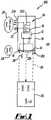
Figure 1 , there is shown generally awarning apparatus 100 installed on a bus 19 (constituting a first vehicle) stopped at a bus stop. - At the bus stop, the bus doors are opened for passengers to alight, and there is a likelihood of pedestrians being present in the area around the bus as indicated in
Figure 1 . The open door condition of the bus is detected by theapparatus 100. Thewarning apparatus 100 includesoptical sensors 16, which are used to detect the presence of a car 26 (constituting a second vehicle) that is approaching thebus 19 from behind, and is due to pull out and overtake the bus.Arrow 21 indicates the general direction of movement of thecar 26. The open door condition of the bus and the presence of car is used to determine a hazard status and generate an alert that is based on the hazard status viadisplays 23a-c and a loudspeaker 22 (constituting alert units). - The apparatus further comprises a control unit 12 (powered by battery 18), also connected a
electrical system 202 of the bus. Thedisplays 23a-c and theloudspeaker 22 are connected to thecontrol unit 12. - In the open door condition, there is generated a corresponding vehicle property signal that is received by the
control unit 12 via theelectrical system 202 of thebus 19. A signal is also fed into thecontrol unit 12 from the sensor upon detection of the second vehicle. - The
control unit 12 is programmed to use the vehicle property signal, and the signal from the sensor to determine the hazard status and to generate a visual alert, via thedisplays 23a-c, accordingly. Thecontrol unit 12 also uses the vehicle property signal to determine whether to activate the warning apparatus. - The
control unit 12 sends a signal to thedisplays 23a-c for producing suitable alert as images or messages, in response to the signal received from thesensor 16. The alert is transmitted by theapparatus 100 to the surrounding environment to inform other road users of the hazard associated with the vehicle. The displayed images and messages provide information relevant to the hazard status. - Having sensed an
optical property 30 of thecar 26 viasensors 16, the control unit generates an alert accordingly, and thedisplays 23a-c produce a visual warning message or image according to the hazard status. Thedisplays - The warning message produced by
rear display 23b can be seen easily by a driver of thecar 26, and alerts the driver of the hazard status in the vicinity of the bus, allowing the car to take appropriate action. In this case, thedisplay 23b produces an image that alternates from the internationally-recognised picture of a woman and a child walking across a road and the message "CAUTION, DANGER - CHILDREN/PEDESTRIANS ALIGHTING", although it will be appreciated that other messages/images may be used in other embodiments. - In a similar way, the
display 23a produces a warning message that may be seen bypedestrians 28, e.g. children, near thebus 19, who have disembarked from the bus and wish to cross the road. Thespeaker 22 produces an audible alert that can be heard by the pedestrians alerting them of the hazard. - The
display 23c produces a warning display with information concerning thecar 26 that can be seen by pedestrians while crossing a road behind thebus 19. Thisdisplay 23c is of particular assistance to people of impaired hearing crossing behind the bus, who are otherwise not able to hear alert messages transmitted from thespeaker 22. Thedisplay 23c is located at the rear offside of thebus 19 to provide an alert prompt to thepedestrians 28 crossing the road at the last point before stepping out from behind thevehicle 19. In this embodiment, the warning alert is formed to be a vertical thin illuminated warning sign located at or near the head height of a child. - The
rear display 23b produces a warning targeted towards the driver of thecar 26, while thedisplays - The warning or alert message is provided temporarily while the bus is near the bus stop. As the
bus 19 moves away a sufficient distance that a reduced or "normal" hazard state has been resumed, the warning apparatus is de-activated. In this example, thecontrol unit 12 is programmed to stop the alert when the bus has pulled away from the bus stop, and reached a certain speed. Figure 2 illustrates schematically at 80 the interaction between various components of thewarning apparatus 100 fitted to thebus 19.- The
apparatus 100 interacts with thebus 19 and receives avehicle property signal 82 from thebus 19 via the electrical system (not shown) upon the opening of the doors of the bus at a bus stop. Theapparatus 100 also receivesdata 31 corresponding to the detected presence of the car 26 (by optical sensors sensing optical property 30). Thevehicle property signal 82 and the presence of thecar 26 are used to determine a hazard status and generate and display an appropriate alert message to thepedestrians 28 and thecar 26. - The
vehicle property signal 82 and presence of thecar 26 are used to activate theapparatus 100 and trigger the control unit to output a display message according to the signal and received data. - Thus, the
apparatus 100 uses the detected presence of thesecond vehicle 26 and the property of thevehicle 19, to determine a hazard status and generate an alert accordingly. Thus, the receivedsignal 82 and/or theproperty 30 of the second motor vehicle is used by theapparatus 100 to produce anddisplay warning alerts motorist 26 andpedestrians 28 that is relevant to the hazard posed by thevehicle 19,pedestrians 28, andsecond vehicle 26. - In other examples, the
apparatus 200 is adapted to comprise speed detection apparatus for detection of the speed of thecar 26. The apparatus may also detect the direction of travel of thecar 26. Figures 3A and 3B illustrate a similar embodiment to that ofFigures 1 and2 with awarning apparatus 100 installed on a use on abus 19, although it differs in that the sensors detect speed of thecar 26. Similar features have the same reference numerals. The bus 19 (passenger carrying vehicle (PCV)) is fitted with side andrear displays 23a,b andspeaker 22 is fitted to outer surfaces of thebus 19. Afurther display 23c is fitted to the offside rear surface of thebus 19. Thecontrol unit 12 is installed internally and may be linked to status of the bus as described above.- The
bus 19 approaches abus stop 63 where passengers are waiting to board the bus. A speedingcar 26 is travelling along aroad 66 nearby and behind the bus 62. - When the bus stops, the doors open to produce a vehicle property signal and the
warning apparatus 100 is activated. Thesensors 16, detect the speed of the speedingcar 26 in the vicinity of thebus 19. - When the car 64 is speeding, the bus displays a warning message to alert road users/drivers of vehicles of the presence of
pedestrians 28, such as children. The warning message produced by the system is a bright red scrolling high visibility display message for capturing the attention of the drivers. - The bus 62 also displays a message via
display 23a to passengers at the bus stop that there is a speeding car and that care should be taken. This message may be a bright yellow scrolling message. Display 23c mounted to the offside of the bus and positioned to transmit a visual alert toward the onside indicates to passengers crossing behind the bus that there is a speeding car approaching. Thedisplay 23c functions to prompt the passengers behind the vehicle, in particular any passengers with impaired hearing, to be careful.- These messages display data concerning the speed or direction of travel of the
car 26 in order that the pedestrians/drivers may take action to avoid an accident. - The driver of the bus manually initiates additional alerts by sending a manual
vehicle property signal 82 to thecontrol unit 12 of the system. As the bus pulls away, the alerts continue to be produced until the bus exceeds a certain speed or a low hazard status has been determined. The system is then de-activated. - In another embodiment,
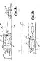
Figure 4 depicts generally at 200 a warning apparatus fitted to abus 219 and configured to warn of potential collision ofpedestrians 228 and acar 226. - In this embodiment, the sensors comprise a speed gun for detecting the speed of the
car 226. The display 223b displays a relevant warning message to the driver of thecar 226. The display alternately shows the messages "SLOW DOWN"; "TOO FAST:" followed by the speed of thecar 26; and/or "BEWARE PEDESTRIANS" and is a moving or scrolling message. The moving message attracts the attention of the driver of thecar 26 and prompts the driver to take positive action to reduce the hazard of the particular road situation. - Messages concerning the
car 226, such as "VEHICLE APPROACHING QUICKLY FROM RIGHT"; "DO NOT CROSS", are displayed to the pedestrians viadisplays 23a and/or 23c in an alternating fashion. These messages are moving messages to catch the attention of the pedestrians and are relevant to the hazard situation, prompting the pedestrians to assess the danger and take action to limit the risk of accident. - The radar guns function to detect the speed of the
second car 226 in front, behind, or to the sides of thebus 19. Theradar guns pedestrian 28 and second vehicle. - In this embodiment, the warning apparatus 210 comprises an
additional sensor 263 fitted toward the front end of thebus 219 which is used to detect a characteristic of thepedestrian 228. More specifically, thesensor 263 functions to detect the speed of the pedestrian. At the same time, the sensors 261a,b located at the rear of thebus 219 are used to measure the speed of thecar 226 moving toward thebus 219 and due to overtake it. - The views of both the
pedestrian 228 and the driver of thevehicle 226 are obstructed, such that the driver of thevehicle 26 can not see thepedestrian 28 and vice versa. Using the measured speed of thepedestrian 28 and the speed of thevehicle 226, thewarning apparatus 200 determines if thesecond vehicle 226 overtaking the first vehicle is likely to collide with thepedestrian 228 crossing the road at apotential impact point 280. - If the
pedestrian 228 and thecar 226 are on a course for collision, an alert is generated and transmitted to thepedestrian 228 and thecar 226 to warn them of the hazard, for example, depending on the likelihood of collision. In this case, the alert to thepedestrian 228 is an audible alert transmitted by the loudspeaker 222. A visible alert is produced and transmitted to the driver of thesecond vehicle 226 via the display 223b. The display produces an alternating scrolling message with the words: "WARNING - POTENTIAL COLLISION"; "YOU ARE ON A COLLISION COURSE WITH A PEDESTRIAN". Thus, a warning that is relevant to the hazard status near the bus is produced by thewarning apparatus 200. - The detected speed of the
pedestrian 228 andcar 226 information is processed by thecontrol unit 12 of the warning apparatus to calculate the point ofpotential collision 280. - In
Figure 5 , there is shown generally at 300 the interaction between various components of a road safety warning system comprising thewarning apparatus 200 fitted on thebus 219. - This is similar to the interaction as described with reference to
Figure 2 , except that thewarning apparatus 200 also takes intoaccount information 231 that is characteristic of thepedestrians 228 in order to determine the information displayed concerning the road hazard. The system warns of an actual impending collision of thepedestrians 228, such as children near the warning apparatus and thecar 226. - In an alternative embodiment (not shown), the
sensor 263 is adapted to detectpedestrians 228 of different heights. A plurality of sensors similar to thesensor 263 are located at different heights for this purpose. By detection of a pedestrian of a specific height, an assumption about the age of the pedestrian may be made and an alert provided accordingly. - In a further embodiment (not shown), a warning apparatus comprises an alternative speed detection system, such as a dual beam optical detection system. In this case, first and second light beams are emitted from the vehicle and are spaced a known distance apart. As a
pedestrian 28 walks across the road, the first and second beams each become modified at different times as thepedestrian 228 passes by. In this way, thepedestrian 228 is detected in two places at two different times, allowing the speed of the pedestrian to be determined. The light beam may for example be a laser beam. - It will be appreciated that in various embodiments, a sensor similar to
sensor 263 for detecting the pedestrian could be positioned and used to detect a pedestrian crossing a road either in front of or behind thefirst vehicle 219. In addition, the pedestrian detection sensors may be controlled by a control computer located on thevehicle 219. This control computer, thepedestrian detection sensor 263 andalert unit 22 may be provided separately from the other components of thewarning apparatus 14. - In yet another embodiment (not shown), the system may include a GPS receiver for receiving information concerning the position of the
first vehicle 219. The information provided via GPS receiver may be used to configure the warning system to produce a display in accordance with the requirements of the locality. For example, GPS data may include speed limit data for the locality that can be used to provide updated information of whether the second vehicle is speeding. The GPS receiver could be used to detect that the vehicle is in an accident hotspot, or close to a bus stop at which passengers are alighting. The warning apparatus may also include a video camera to record an image a second vehicle. The image data may be referred to in the event of an accident. - Further, in other embodiments, the bus may also include a transmitter, activatable to transmit an alert signal containing the position of the first vehicle. This alert signal is used to alert emergency services, for example, if a collision arises in the vicinity of the bus. The signal could be picked up by a GPS receiver of an emergency vehicle. If the collision occurs under suspicious circumstances security services are alerted. The transmission of a signal could be controlled by the driver, for example, by signal may be sent when the driver depresses a control button, or could be generated automatically.
- Different levels of alert may be communicated in this way. Similarly, if the driver is at risk of being assaulted, the driver may transmit an alert in this way. The rapid provision to the emergency services of an accurate GPS position helps to improve response time of emergency services in the event of an accident.
- The apparatus thus obtains information and data concerning a traffic situation and may obtain information concerning speed, distance, or position of a second vehicle, to determine a hazard status and transmit a suitable alert.
- In summary, the present apparatus and method provides an alert to a road user according to a hazard status, such as the level of a hazard, and warns the road user based on data acquired by the system that is relevant to the actual situation, e.g., data containing a detected property of an overtaking car and a property of the vehicle corresponding to a likely presence of pedestrians near the vehicle. In embodiments of the invention, hazard detection equipment and display signs are located on a vehicle to obtain and display data relating to the hazard, and to warn other road users of the hazard.
- This reduces the risk of users ignoring the warnings, improves road safety and reduces the risk of accidents occurring.
- The warnings are made relevant by obtaining and/or measuring real time data concerning road users in the area nearby the vehicle and producing an alert based on these data. This serves to improve safety in the region near the
vehicle 19 that is a safety hazard. - The use of signs to display information, such as speed information, is a particular advantage as when such information is considered by a conscientious driver, the driver is likely to feel duty bound to reduce their speed, particularly where children are likely to be at risk.
- Various modifications and improvements may be made without departing from the invention described herein.
- It will be appreciated that sensors could be located at the front, rear or side of the
bus 19. - In another embodiment, a message could be transmitted via a display mounted near the front of a
bus 19 to warn a pedestrian of being on a collision course with an oncoming car. - It will be appreciated that the apparatus described could be de-activated after a fixed time period has elapsed or when the speed or acceleration of the bus is detected as being over a predetermined threshold.
- In other embodiments, a vehicle property signal can be generated manually by a driver of the
bus 19 by pressing a control button in situations where the driver considers there to be a risk; the vehicle property signal conveying information concerning the behaviour of thebus 19, such as its speed, location, acceleration or opening of doors. The vehicle property signal might be generated automatically. In a yet further embodiment, a property of the bus might be detected by sensors to produce a vehicle property signal that is sent automatically from the sensors. Such sensors might, for example, detect that the bus has stopped, or that the door of the bus has opened. Alternatively, the sensor may detect that a passenger has alighted from the bus, for example by an optical sensor or pressure sensor. - The apparatus may also include memory storage to record data from the sensors over a time period.
- It will be appreciated that the sensors 261,263 could comprise a transmitter and receiver for transmitting a signal and receiving a response from a vehicle or pedestrian. The sensors for detecting a pedestrian could comprise a radar transmitter-receiver for detecting position, speed, and distance parameters, and may comprise a radar gun.
Claims (32)
- Warning apparatus (100, 200) comprising:- a control unit (12);- at least one alert unit (22, 23) adapted to be activated by the control unit (12) to provide an alert in response to detection of a hazard posed by a road user- means for detecting a property of a first vehicle (19, 219) corresponding to a likelihood of pedestrians (28, 228) being present in the vicinity of the first vehicle;characterised in that:- the apparatus is adapted for installation on the first vehicle (19,219) whereby the alert unit (22, 23) provides an alert to the exterior of the first vehicle;- the apparatus includes means (16) for detecting a property of a second vehicle (26,226) corresponding to a likelihood of pedestrians (28,228) being present in the vicinity of the second vehicle;and wherein the apparatus is adapted to detect the hazard using the detected properties of the first and second vehicles (19, 26), and wherein the control unit (12) is adapted to activate the alert unit (22, 23) to generate an alert (42) in response to the detection of the hazard.
- Warning apparatus as claimed in claim 1, wherein the road user is a pedestrian (28,228) in the vicinity of the first vehicle (19,219).
- Warning apparatus as claimed in claim 1 or claim 2, wherein the road user is the second vehicle (26,226) or the driver of the second vehicle (26,226).
- Warning apparatus as claimed in any preceding claim, in which the first vehicle is a bus (19,219) for transporting passengers.
- Warning apparatus as claimed in any one of the preceding claims, wherein the property of the first vehicle (19,219) is selected from the group comprising:- a speed of the first vehicle;- a behaviour of the first vehicle;- an open door status of the first vehicle;- an acceleration or deceleration of the vehicle;- a location of the above vehicle in a high accident risk environment;- status of manually-activated controls;- a position of the first vehicle; and- a direction of travel of the first vehicle.
- Warning apparatus as claimed in any one of the preceding claims, wherein the property of the second vehicle (26,226) comprises one or more of:- a speed of the second vehicle;- a behaviour of the second vehicle- a distance from the first vehicle to the second vehicle;- a position of the second vehicle;- a direction of travel of the second vehicle; and- a presence of the second vehicle.
- Warning apparatus as claimed in any one of the preceding claims, wherein the means for detecting the property of the second vehicle comprises at least one sensor (16) adapted to detect the property.
- Warning apparatus as claimed in any one of the preceding claims, wherein the apparatus is operative to determine a likelihood of collision between a pedestrian (28,228) and the second vehicle (26,226).
- Warning apparatus as claimed in Claim 8, wherein the apparatus comprises means for detecting a property of the pedestrian, and the likelihood of collision is determined using the detected property of the pedestrian (28,228) and the second vehicle (26,226).
- Warning apparatus as claimed in Claim 9, wherein the property of the pedestrian (28,228) comprises a direction of travel of the pedestrian (28,228).
- Warning apparatus as claimed in any one of the preceding claims, wherein the road user to which the alert is generated is one or more of: the first vehicle (19,219); the second vehicle (26,226); and at least one pedestrian (28,228).
- Warning apparatus as claimed in any one of the preceding claims, wherein the apparatus comprises a display operable to provide a visible alert to the road user.
- Warning apparatus as claimed in any one of the preceding claims, wherein the apparatus comprises a display configured to display data recorded by the apparatus, the data corresponding to the detected property of the second vehicle (26,226).
- Warning apparatus as claimed in any one of the preceding claims, wherein the apparatus comprises at least one loudspeaker (22) to produce an audible alert in the vicinity of the first vehicle.
- Warning apparatus as claimed in any preceding claim, wherein the alert unit (22,23) is located on an external surface of the first vehicle (19,219).
- Warning apparatus as claimed in any one of the preceding claims, wherein the apparatus comprises a video camera operable for obtaining image data of the road user.
- Warning apparatus as claimed in any one of the preceding claims, wherein the apparatus comprises a GPS receiver for locating the first vehicle.
- Warning apparatus as claimed in any one of the preceding claims, wherein the apparatus comprises a transmitter configured to transmit a signal for informing emergency services of a position of the first vehicle.
- Warning apparatus as claimed in any of any one of the preceding claims, wherein the apparatus comprises a speed detecting apparatus for measuring a speed of the second vehicle (26,226).
- A passenger carrying vehicle (PCV) comprising the warning apparatus as claimed in any one of Claims 1 to 19.
- A method for warning a road user of a hazard, the method comprising the steps of:- providing a control unit (12) on a first vehicle (19,219);- providing at least one alert unit (22, 23) on the first vehicle, adapted to be activated by the control unit (12) to provide an alert to the exterior of the first vehicle (19,219);- providing detection means on the first vehicle (19,219);- detecting a property of the first vehicle (19,219) corresponding to a likelihood of pedestrians (28,228) being present in the vicinity of the first vehicle (19,219);- detecting a property of a second vehicle (28,228) corresponding to a likelihood of pedestrians (28,228) being present in the vicinity of the second vehicle;- using the detected properties of the first and second vehicles (19, 28) to detect a hazard posed by a road user, andactivating the alert unit (22, 23) via the control unit (12) to generate an alert in response to the detection of the hazard.
- A method as claimed in Claim 21, wherein the method comprises the step of detecting a speed of the second vehicle (26,226).
- A method as claimed in Claim 21 or Claim 22, wherein the method comprises the steps of: detecting an opening of doors of the first vehicle (19,219); and using the opening of doors in determining the hazard status.
- A method as claimed in any one of Claims 21 to 23, wherein the method comprises the steps of: detecting a position of the first vehicle (19,219) in a hazardous location; and using the position in determining the hazard status.
- A method as claimed in any one of Claims 21 to 24, wherein the method comprises the steps of: detecting a pedestrian (28,228) in the vicinity of the vehicle (19,219); and using the detection of the pedestrian (28,228) in determining the hazard status.
- A method as claimed in any one of Claims 21 to 25, wherein the method comprises the steps of: detecting a direction of travel of a pedestrian (28,228); and using the direction of travel of the pedestrian (28,228) to determine a likelihood of collision of the pedestrian (28,228) and the second vehicle (26,226).
- A method as claimed in Claim 26, wherein the method comprises the steps of: detecting a direction of travel of the second vehicle (26,226); and using the direction of travel of the second vehicle (26,226) in determining the likelihood of collision of the pedestrian (28,228) and the second vehicle (26,226).
- A method as claimed in any one of Claims 21 to 27, wherein the method comprises the step of alerting the second vehicle (26,226) of a hazard.
- A method as claimed in any one of Claims 21 to 28, wherein the method comprises the step of alerting a pedestrian (28,228) of a hazard.
- A method as claimed in any one of Claims 21 to 29, wherein the method comprises the step of displaying an alert message to a road user according to the hazard status.
- A method as claimed in any one of Claims 21 to 30, wherein the method comprises the step of displaying a visible alert to the road user according to the hazard status.
- A method as claimed in any one of Claims 21 to 31, wherein the method comprises the step of informing emergency services of a position of the first vehicle (19,219).
Applications Claiming Priority (3)
| Application Number | Priority Date | Filing Date | Title |
|---|---|---|---|
| GB0606279AGB2436916B (en) | 2006-03-29 | 2006-03-29 | Warning System |
| GBGB0610203.2AGB0610203D0 (en) | 2006-03-29 | 2006-05-23 | Warning system |
| PCT/GB2007/001153WO2007110654A1 (en) | 2006-03-29 | 2007-03-29 | Warning apparatus and method |
Publications (2)
| Publication Number | Publication Date |
|---|---|
| EP2002415A1 EP2002415A1 (en) | 2008-12-17 |
| EP2002415B1true EP2002415B1 (en) | 2017-03-08 |
Family
ID=36424802
Family Applications (1)
| Application Number | Title | Priority Date | Filing Date |
|---|---|---|---|
| EP07732207.1ANot-in-forceEP2002415B1 (en) | 2006-03-29 | 2007-03-29 | Warning apparatus and method |
Country Status (7)
| Country | Link |
|---|---|
| US (1) | US8258981B2 (en) |
| EP (1) | EP2002415B1 (en) |
| JP (1) | JP2009531766A (en) |
| CA (1) | CA2681386C (en) |
| ES (1) | ES2628016T3 (en) |
| GB (2) | GB2436916B (en) |
| WO (1) | WO2007110654A1 (en) |
Families Citing this family (78)
| Publication number | Priority date | Publication date | Assignee | Title |
|---|---|---|---|---|
| FR2916399B1 (en)* | 2007-05-25 | 2010-01-29 | Peugeot Citroen Automobiles Sa | MONITORING DEVICE FOR STOPPED TRANSPORT VEHICLE |
| WO2010020832A1 (en)* | 2008-08-22 | 2010-02-25 | Renault Trucks | A system for providing information related to a vehicle stop occurrence |
| WO2010036198A1 (en)* | 2008-09-25 | 2010-04-01 | Binar Akteibolag (Publ) | Warning system |
| GB0822478D0 (en)* | 2008-12-10 | 2009-01-14 | Mcguire Alastair D | Bus pedestrian safety control |
| US20100225461A1 (en)* | 2009-03-05 | 2010-09-09 | Raja Singh Tuli | Apparatus and method for detection of a specified audio signal or gesture |
| DE102009052589A1 (en)* | 2009-11-10 | 2011-05-12 | Valeo Schalter Und Sensoren Gmbh | Device and method for monitoring and signaling of traffic situations and operating conditions in a vehicle and in the environment of the vehicle |
| US8537030B2 (en) | 2010-02-15 | 2013-09-17 | Ford Global Technologies, Llc | Pedestrian alert system and method |
| CN102782741B (en)* | 2010-03-03 | 2015-08-19 | 本田技研工业株式会社 | Vehicle periphery monitoring device |
| BE1019256A5 (en)* | 2010-03-24 | 2012-05-08 | Guillet Aurelie | PROTECTION OF PIETONS CROSSING BEFORE OR BEHIND A BUS. |
| SE535225C2 (en)* | 2010-10-07 | 2012-05-29 | Scania Cv Ab | Procedure and warning system for objects in connection with a motor vehicle |
| RU2469890C2 (en)* | 2010-10-15 | 2012-12-20 | Александр Андреевич Меньтюков | Method for traffic safety ensuring |
| EP2543544B1 (en)* | 2011-07-04 | 2018-05-02 | Iveco France S.A.S. | Safety device for passenger transport vehicle, passenger transport vehicle comprising such a device and method for applying such a device |
| EP2798307A4 (en)* | 2011-12-29 | 2015-08-12 | Intel Corp | Navigation systems that enhance driver awareness |
| RU2495775C2 (en)* | 2011-12-29 | 2013-10-20 | Федеральное государственное бюджетное образовательное учреждение высшего профессионального образования Марийский государственный технический университет | Method of increasing pedestrian crossing safety |
| WO2014049987A1 (en)* | 2012-09-28 | 2014-04-03 | パナソニック株式会社 | Notification device and vehicle using same |
| TW201416268A (en)* | 2012-10-25 | 2014-05-01 | Wistron Neweb Corp | Automobile warning method and automobile warning system utilizing the same |
| TWI486611B (en)* | 2013-04-18 | 2015-06-01 | Wistron Neweb Corp | Radar device for an automotive radar system |
| DE102013210080A1 (en)* | 2013-05-29 | 2014-12-04 | Robert Bosch Gmbh | Vehicle device and method for warning an object |
| US20150025924A1 (en)* | 2013-07-22 | 2015-01-22 | Palo Alto Investors | Methods of displaying information to a user, and systems and devices for use in practicing the same |
| DE102013017626A1 (en)* | 2013-10-23 | 2015-04-23 | Audi Ag | Method for warning other road users from pedestrians by a motor vehicle and motor vehicle |
| DK178269B1 (en)* | 2014-04-04 | 2015-10-26 | Fairwood Innovation As | A warning system for a vehicle and a vehicle comprising such a warning system |
| US9655390B2 (en)* | 2014-05-19 | 2017-05-23 | Donnell A. Davis | Wearable pedestrian safety radar system |
| DE112014006827T5 (en)* | 2014-07-22 | 2017-04-13 | Mitsubishi Electric Corporation | Driving assistance system, driving support procedure and program |
| CN104240538B (en)* | 2014-09-11 | 2016-08-17 | 奇瑞汽车股份有限公司 | A kind of driving method for early warning and device |
| GB201818058D0 (en)* | 2015-05-18 | 2018-12-19 | Mobileye Vision Technologies Ltd | Safety system for a vehicle to detect and warn of a potential collision |
| US9744809B2 (en)* | 2015-11-05 | 2017-08-29 | Continental Automotive Systems, Inc. | Enhanced sound generation for quiet vehicles |
| US9840252B2 (en) | 2015-12-03 | 2017-12-12 | International Business Machines Corporation | System and method for vehicle assisted response to road conditions |
| CN105835774A (en)* | 2016-06-08 | 2016-08-10 | 成都谷辘信息技术有限公司 | Vehicle collision warning system based on GPS (Global Position System) |
| CN105922934A (en)* | 2016-06-08 | 2016-09-07 | 成都谷辘信息技术有限公司 | Vehicle anti-collision early-warning device based on GPS |
| IT201600093356A1 (en)* | 2016-09-16 | 2018-03-16 | Matteo Campoleoni | SIDE MIRROR FOR VEHICLES AND ASSOCIATED SAFETY DEVICE. |
| CN109789880B (en)* | 2016-09-21 | 2022-03-11 | 苹果公司 | External communication of vehicle |
| US10089862B2 (en) | 2016-10-26 | 2018-10-02 | Microsoft Technology Licensing, Llc | Pedestrian alerts for mobile devices |
| US10580294B2 (en)* | 2016-11-14 | 2020-03-03 | Jacques Bedard | Photographic system for use on school buses |
| WO2018160724A1 (en) | 2017-02-28 | 2018-09-07 | Wayfarer, Inc. | Transportation system |
| JP6465317B2 (en) | 2017-03-10 | 2019-02-06 | 株式会社Subaru | Image display device |
| JP6497818B2 (en) | 2017-03-10 | 2019-04-10 | 株式会社Subaru | Image display device |
| JP6515125B2 (en) | 2017-03-10 | 2019-05-15 | 株式会社Subaru | Image display device |
| JP6429413B2 (en)* | 2017-03-10 | 2018-11-28 | 株式会社Subaru | Image display device |
| JP6593803B2 (en) | 2017-03-10 | 2019-10-23 | 株式会社Subaru | Image display device |
| JP6465318B2 (en) | 2017-03-10 | 2019-02-06 | 株式会社Subaru | Image display device |
| JP6497819B2 (en) | 2017-03-10 | 2019-04-10 | 株式会社Subaru | Image display device |
| EP3379222B1 (en) | 2017-03-22 | 2020-12-30 | Methode Electronics Malta Ltd. | Magnetoelastic based sensor assembly |
| JP2018195159A (en)* | 2017-05-19 | 2018-12-06 | パイオニア株式会社 | Information processing device, information notification method, and program |
| US11618380B2 (en) | 2017-06-12 | 2023-04-04 | Continental Automotive Gmbh | Rear pre-crash safety system |
| DE102017210605A1 (en)* | 2017-06-23 | 2018-12-27 | Robert Bosch Gmbh | Method for monitoring a monitoring area located behind a vehicle |
| US11488393B2 (en)* | 2017-11-14 | 2022-11-01 | AWARE Technologies | Systems and methods for moving object predictive locating, reporting, and alerting |
| US20230046309A1 (en)* | 2017-11-14 | 2023-02-16 | Joshua MAY | Moving Target of Interest Predictive Locating, Reporting, and Alerting |
| JP6978962B2 (en)* | 2018-02-22 | 2021-12-08 | 株式会社日立製作所 | Mobile control system and control method |
| US11014417B2 (en) | 2018-02-27 | 2021-05-25 | Methode Electronics, Inc. | Towing systems and methods using magnetic field sensing |
| DE18907724T1 (en) | 2018-02-27 | 2021-03-25 | Methode Electronics, Inc. | Towing systems and methods using magnetic field measurement |
| US11135882B2 (en) | 2018-02-27 | 2021-10-05 | Methode Electronics, Inc. | Towing systems and methods using magnetic field sensing |
| US11221262B2 (en) | 2018-02-27 | 2022-01-11 | Methode Electronics, Inc. | Towing systems and methods using magnetic field sensing |
| US11084342B2 (en) | 2018-02-27 | 2021-08-10 | Methode Electronics, Inc. | Towing systems and methods using magnetic field sensing |
| US11491832B2 (en) | 2018-02-27 | 2022-11-08 | Methode Electronics, Inc. | Towing systems and methods using magnetic field sensing |
| US10235882B1 (en) | 2018-03-19 | 2019-03-19 | Derq Inc. | Early warning and collision avoidance |
| US11206375B2 (en) | 2018-03-28 | 2021-12-21 | Gal Zuckerman | Analyzing past events by utilizing imagery data captured by a plurality of on-road vehicles |
| EP3598259B1 (en)* | 2018-07-19 | 2021-09-01 | Panasonic Intellectual Property Management Co., Ltd. | Information processing method and information processing system |
| US11138418B2 (en) | 2018-08-06 | 2021-10-05 | Gal Zuckerman | Systems and methods for tracking persons by utilizing imagery data captured by on-road vehicles |
| WO2020085442A1 (en)* | 2018-10-24 | 2020-04-30 | ヤマハ発動機株式会社 | Autonomous driving vehicle |
| LU101212B1 (en)* | 2019-05-15 | 2020-11-16 | Alpha Ec Ind 2018 S A R L | Bus with a safety lighting system for road users |
| LU101213B1 (en) | 2019-05-15 | 2020-11-16 | Alpha Ec Ind 2018 S A R L | Bus with a variable height warning signal |
| US11007929B2 (en)* | 2019-05-29 | 2021-05-18 | GM Global Technology Operations LLC | Multimodal vehicle-to-pedestrian notification system |
| JP2022546320A (en) | 2019-08-29 | 2022-11-04 | ディーイーアールキュー インコーポレイテッド | Advanced in-vehicle equipment |
| US11396258B2 (en) | 2019-09-16 | 2022-07-26 | Federal Signal Corporation | Self-adapting emergency vehicle lighting system |
| EP4121331A4 (en) | 2020-03-20 | 2024-05-01 | Glydways, Inc. | VEHICLE CONTROL DIAGRAMS FOR AUTONOMOUS VEHICLE SYSTEM |
| EP3886076B1 (en) | 2020-03-27 | 2025-09-10 | Aptiv Technologies AG | Warning system for a host automotive vehicle |
| US11488467B1 (en) | 2020-09-02 | 2022-11-01 | Wm Intellectual Property Holdings, L.L.C. | System and method for oncoming vehicle detection and alerts for a waste collection vehicle |
| US11731662B2 (en)* | 2020-10-08 | 2023-08-22 | Ford Global Technologies, Llc | Autonomous vehicle system for detecting pedestrian presence |
| US11361201B2 (en) | 2020-10-08 | 2022-06-14 | Argo AI, LLC | Systems and methods for determining an object type and an attribute for an observation based on fused sensor data |
| IT202100003947A1 (en)* | 2021-02-25 | 2021-05-25 | Gianfranco Rossi | Safety system to reduce gravity or avoid collisions with pedestrians and crossing objects |
| CN113470306B (en)* | 2021-06-24 | 2023-02-14 | 福建省高速公路集团有限公司 | Highway construction safety early warning system and method |
| IT202100017156A1 (en)* | 2021-06-30 | 2022-12-30 | Tp Automotive S R L | SAFETY SYSTEM FOR COLLECTIVE TRANSPORT MEANS |
| IT202100020333A1 (en) | 2021-07-29 | 2023-01-29 | Impresa Edile Favaro Roberto | A SIGNALING SYSTEM |
| JP2023104107A (en)* | 2022-01-17 | 2023-07-28 | トヨタ自動車株式会社 | Boarding time notification method |
| US12065075B2 (en)* | 2022-04-20 | 2024-08-20 | Ford Global Technologies, Llc | Systems and methods for facilitating safe school bus operations |
| JP2024046031A (en)* | 2022-09-22 | 2024-04-03 | 本田技研工業株式会社 | Attention attracting system and attention attracting method |
| JP7697919B2 (en)* | 2022-12-19 | 2025-06-24 | Necプラットフォームズ株式会社 | Attention calling method selection device, attention calling method selection method, and program |
| US12337752B2 (en) | 2023-01-25 | 2025-06-24 | Volvo Car Corporation | Pedestrian crossing management using autonomous vehicles |
Family Cites Families (20)
| Publication number | Priority date | Publication date | Assignee | Title |
|---|---|---|---|---|
| US5210521A (en)* | 1990-07-26 | 1993-05-11 | Gary M. Hojell | Vehicle alarm apparatus and method for preventing injury to nearby persons |
| US5281947A (en)* | 1991-09-20 | 1994-01-25 | C.A.R.E., Inc. | Vehicular safety sensor and warning system |
| US5493269A (en)* | 1991-09-20 | 1996-02-20 | C.A.R.E., Inc. | Vehicular safety sensor and warning system |
| US5382953A (en)* | 1994-04-14 | 1995-01-17 | Hauptli; Wayne L. | Device for detecting school bus stop arm violations |
| US5793420A (en)* | 1994-10-28 | 1998-08-11 | Schmidt; William P. | Video recording system for vehicle |
| CA2151064A1 (en)* | 1995-06-06 | 1996-12-07 | Douglas Stewart White | Driving distance detector (3-d safety) |
| FR2750522B3 (en)* | 1996-07-01 | 1998-08-28 | Grand Clement Jean Luc | SYSTEM FOR THE PREVENTION OF EXCESSIVE SPEED ON THE ROAD |
| FR2803568A1 (en)* | 2000-01-11 | 2001-07-13 | Salvatore Tribuiani | System, for alerting vehicles behind halted vehicle that pedestrians are crossing road, includes danger alerting unit, on rear of vehicle, and sensors at front to detect presence of human or animal in front of vehicle |
| US6601669B1 (en)* | 2000-10-06 | 2003-08-05 | Continental Teves, Inc. | Safety interlock system for motor vehicles |
| US20020097146A1 (en)* | 2001-01-24 | 2002-07-25 | Harris Troy Whitfield | School bus driver's vision enhancement system |
| AUPR834201A0 (en)* | 2001-10-18 | 2001-11-08 | A.D. Engineering Pty Ltd | Road sign |
| US6933837B2 (en)* | 2002-01-25 | 2005-08-23 | Altra Technologies Incorporated | Trailer based collision warning system and method |
| EP1351207B1 (en) | 2002-04-05 | 2006-03-01 | Jcdecaux SA | Street furniture with road safety |
| DE10229033A1 (en) | 2002-06-28 | 2004-01-22 | Robert Bosch Gmbh | Method and device for recognizing an accident risk |
| US6864784B1 (en)* | 2002-07-19 | 2005-03-08 | Barry Loeb | Vehicle speed and safety warning system |
| GB2393835B (en)* | 2002-08-10 | 2005-02-23 | Martin Christopher Durant | Tailgate tracker |
| WO2004066240A2 (en)* | 2003-01-21 | 2004-08-05 | Byron King | Gps based vehicle warning and location system and method |
| US7095336B2 (en)* | 2003-09-23 | 2006-08-22 | Optimus Corporation | System and method for providing pedestrian alerts |
| US7526103B2 (en)* | 2004-04-15 | 2009-04-28 | Donnelly Corporation | Imaging system for vehicle |
| JP4610305B2 (en)* | 2004-11-08 | 2011-01-12 | アルパイン株式会社 | Alarm generating method and alarm generating device |
- 2006
- 2006-03-29GBGB0606279Apatent/GB2436916B/ennot_activeExpired - Fee Related
- 2006-05-23GBGBGB0610203.2Apatent/GB0610203D0/ennot_activeCeased
- 2007
- 2007-03-29WOPCT/GB2007/001153patent/WO2007110654A1/enactiveApplication Filing
- 2007-03-29EPEP07732207.1Apatent/EP2002415B1/ennot_activeNot-in-force
- 2007-03-29CACA2681386Apatent/CA2681386C/ennot_activeExpired - Fee Related
- 2007-03-29JPJP2009502217Apatent/JP2009531766A/enactivePending
- 2007-03-29USUS12/295,120patent/US8258981B2/ennot_activeExpired - Fee Related
- 2007-03-29ESES07732207.1Tpatent/ES2628016T3/enactiveActive
Also Published As
| Publication number | Publication date |
|---|---|
| EP2002415A1 (en) | 2008-12-17 |
| GB0610203D0 (en) | 2006-07-05 |
| CA2681386C (en) | 2015-11-24 |
| US8258981B2 (en) | 2012-09-04 |
| GB2436916B (en) | 2008-09-24 |
| GB2436916A (en) | 2007-10-10 |
| GB0606279D0 (en) | 2006-05-10 |
| WO2007110654A1 (en) | 2007-10-04 |
| CA2681386A1 (en) | 2007-10-04 |
| JP2009531766A (en) | 2009-09-03 |
| ES2628016T3 (en) | 2017-08-01 |
| US20090160678A1 (en) | 2009-06-25 |
Similar Documents
| Publication | Publication Date | Title |
|---|---|---|
| EP2002415B1 (en) | Warning apparatus and method | |
| CN206049585U (en) | collision warning system | |
| CN112771592B (en) | Method for warning a driver of a motor vehicle, control device and motor vehicle | |
| CN207257509U (en) | collision warning system for vehicle | |
| US20130311075A1 (en) | Motorcycle and helmet providing advance driver assistance | |
| KR101791601B1 (en) | Intelligent traffic safety system and its operation method | |
| JP5613398B2 (en) | Intersection driving support device | |
| US8669857B2 (en) | Hand-held device integration for automobile safety | |
| US6556148B2 (en) | Emergency flashing light mechanism | |
| US8471726B2 (en) | System and method for collision warning | |
| US5973618A (en) | Intelligent walking stick | |
| US20030154017A1 (en) | Apparatus and method for vehicle counting, tracking and tagging | |
| US7414541B2 (en) | Vehicle communication device and method of controlling the same | |
| KR20140046953A (en) | Device and method for warning collision | |
| US20040155795A1 (en) | Systems and methods for motor vehicle-based emergency/hazard detection | |
| CN112298024A (en) | Avoidance reminding system and method, vehicle and computer storage medium | |
| CN107009959A (en) | Method from warning to driver and warning system for providing | |
| JP2024097875A (en) | Systems and programs | |
| JP2005327177A (en) | System and device for supporting inter-vehicle collision prevention | |
| JPH1153695A (en) | Curve alarm | |
| CN112298017A (en) | Interactive system, method and computer storage medium | |
| CN115668329B (en) | Reduce the risk of collision with obscured motor vehicles | |
| KR102795936B1 (en) | Traffic signal system for preventing sudden deacceleration of vehicle, and traffic signal providing method for the same | |
| KR102200495B1 (en) | Device for warning pedestrian nearby vehicle driving | |
| JP2006021644A (en) | Crossing accident prevention system |
Legal Events
| Date | Code | Title | Description |
|---|---|---|---|
| PUAI | Public reference made under article 153(3) epc to a published international application that has entered the european phase | Free format text:ORIGINAL CODE: 0009012 | |
| 17P | Request for examination filed | Effective date:20081013 | |
| AK | Designated contracting states | Kind code of ref document:A1 Designated state(s):AT BE BG CH CY CZ DE DK EE ES FI FR GB GR HU IE IS IT LI LT LU LV MC MT NL PL PT RO SE SI SK TR | |
| 17Q | First examination report despatched | Effective date:20110309 | |
| DAX | Request for extension of the european patent (deleted) | ||
| GRAP | Despatch of communication of intention to grant a patent | Free format text:ORIGINAL CODE: EPIDOSNIGR1 | |
| RIC1 | Information provided on ipc code assigned before grant | Ipc:G08G 1/16 20060101AFI20160428BHEP Ipc:B60Q 1/52 20060101ALI20160428BHEP Ipc:B60Q 5/00 20060101ALI20160428BHEP Ipc:G08G 1/123 20060101ALI20160428BHEP Ipc:G08G 1/0955 20060101ALI20160428BHEP | |
| INTG | Intention to grant announced | Effective date:20160520 | |
| GRAS | Grant fee paid | Free format text:ORIGINAL CODE: EPIDOSNIGR3 | |
| GRAA | (expected) grant | Free format text:ORIGINAL CODE: 0009210 | |
| AK | Designated contracting states | Kind code of ref document:B1 Designated state(s):AT BE BG CH CY CZ DE DK EE ES FI FR GB GR HU IE IS IT LI LT LU LV MC MT NL PL PT RO SE SI SK TR | |
| REG | Reference to a national code | Ref country code:GB Ref legal event code:FG4D | |
| REG | Reference to a national code | Ref country code:CH Ref legal event code:EP Ref country code:AT Ref legal event code:REF Ref document number:874161 Country of ref document:AT Kind code of ref document:T Effective date:20170315 | |
| REG | Reference to a national code | Ref country code:IE Ref legal event code:FG4D | |
| REG | Reference to a national code | Ref country code:DE Ref legal event code:R096 Ref document number:602007050072 Country of ref document:DE | |
| REG | Reference to a national code | Ref country code:FR Ref legal event code:PLFP Year of fee payment:11 | |
| REG | Reference to a national code | Ref country code:NL Ref legal event code:FP | |
| REG | Reference to a national code | Ref country code:CH Ref legal event code:PUE Owner name:ARTEMIS SAFETY LTD., GB Free format text:FORMER OWNER: TURNBULL, JOHN, GB | |
| RAP2 | Party data changed (patent owner data changed or rights of a patent transferred) | Owner name:ARTEMIS SAFETY LTD. | |
| RIN2 | Information on inventor provided after grant (corrected) | Inventor name:ARTEMIS SAFETY LTD. | |
| REG | Reference to a national code | Ref country code:LT Ref legal event code:MG4D | |
| PG25 | Lapsed in a contracting state [announced via postgrant information from national office to epo] | Ref country code:GR Free format text:LAPSE BECAUSE OF FAILURE TO SUBMIT A TRANSLATION OF THE DESCRIPTION OR TO PAY THE FEE WITHIN THE PRESCRIBED TIME-LIMIT Effective date:20170609 Ref country code:FI Free format text:LAPSE BECAUSE OF FAILURE TO SUBMIT A TRANSLATION OF THE DESCRIPTION OR TO PAY THE FEE WITHIN THE PRESCRIBED TIME-LIMIT Effective date:20170308 Ref country code:LT Free format text:LAPSE BECAUSE OF FAILURE TO SUBMIT A TRANSLATION OF THE DESCRIPTION OR TO PAY THE FEE WITHIN THE PRESCRIBED TIME-LIMIT Effective date:20170308 | |
| PGFP | Annual fee paid to national office [announced via postgrant information from national office to epo] | Ref country code:GB Payment date:20170605 Year of fee payment:11 | |
| REG | Reference to a national code | Ref country code:ES Ref legal event code:FG2A Ref document number:2628016 Country of ref document:ES Kind code of ref document:T3 Effective date:20170801 | |
| REG | Reference to a national code | Ref country code:AT Ref legal event code:MK05 Ref document number:874161 Country of ref document:AT Kind code of ref document:T Effective date:20170308 | |
| REG | Reference to a national code | Ref country code:NL Ref legal event code:PD Owner name:ARTEMIS SAFETY LTD.; GB Free format text:DETAILS ASSIGNMENT: CHANGE OF OWNER(S), ASSIGNMENT; FORMER OWNER NAME: TURNBULL, JOHN Effective date:20170607 | |
| PG25 | Lapsed in a contracting state [announced via postgrant information from national office to epo] | Ref country code:LV Free format text:LAPSE BECAUSE OF FAILURE TO SUBMIT A TRANSLATION OF THE DESCRIPTION OR TO PAY THE FEE WITHIN THE PRESCRIBED TIME-LIMIT Effective date:20170308 Ref country code:SE Free format text:LAPSE BECAUSE OF FAILURE TO SUBMIT A TRANSLATION OF THE DESCRIPTION OR TO PAY THE FEE WITHIN THE PRESCRIBED TIME-LIMIT Effective date:20170308 Ref country code:BG Free format text:LAPSE BECAUSE OF FAILURE TO SUBMIT A TRANSLATION OF THE DESCRIPTION OR TO PAY THE FEE WITHIN THE PRESCRIBED TIME-LIMIT Effective date:20170608 | |
| PG25 | Lapsed in a contracting state [announced via postgrant information from national office to epo] | Ref country code:CZ Free format text:LAPSE BECAUSE OF FAILURE TO SUBMIT A TRANSLATION OF THE DESCRIPTION OR TO PAY THE FEE WITHIN THE PRESCRIBED TIME-LIMIT Effective date:20170308 Ref country code:EE Free format text:LAPSE BECAUSE OF FAILURE TO SUBMIT A TRANSLATION OF THE DESCRIPTION OR TO PAY THE FEE WITHIN THE PRESCRIBED TIME-LIMIT Effective date:20170308 Ref country code:RO Free format text:LAPSE BECAUSE OF FAILURE TO SUBMIT A TRANSLATION OF THE DESCRIPTION OR TO PAY THE FEE WITHIN THE PRESCRIBED TIME-LIMIT Effective date:20170308 Ref country code:SK Free format text:LAPSE BECAUSE OF FAILURE TO SUBMIT A TRANSLATION OF THE DESCRIPTION OR TO PAY THE FEE WITHIN THE PRESCRIBED TIME-LIMIT Effective date:20170308 Ref country code:AT Free format text:LAPSE BECAUSE OF FAILURE TO SUBMIT A TRANSLATION OF THE DESCRIPTION OR TO PAY THE FEE WITHIN THE PRESCRIBED TIME-LIMIT Effective date:20170308 | |
| PG25 | Lapsed in a contracting state [announced via postgrant information from national office to epo] | Ref country code:PL Free format text:LAPSE BECAUSE OF FAILURE TO SUBMIT A TRANSLATION OF THE DESCRIPTION OR TO PAY THE FEE WITHIN THE PRESCRIBED TIME-LIMIT Effective date:20170308 Ref country code:PT Free format text:LAPSE BECAUSE OF FAILURE TO SUBMIT A TRANSLATION OF THE DESCRIPTION OR TO PAY THE FEE WITHIN THE PRESCRIBED TIME-LIMIT Effective date:20170710 Ref country code:IS Free format text:LAPSE BECAUSE OF FAILURE TO SUBMIT A TRANSLATION OF THE DESCRIPTION OR TO PAY THE FEE WITHIN THE PRESCRIBED TIME-LIMIT Effective date:20170708 | |
| REG | Reference to a national code | Ref country code:DE Ref legal event code:R097 Ref document number:602007050072 Country of ref document:DE | |
| PLBE | No opposition filed within time limit | Free format text:ORIGINAL CODE: 0009261 | |
| STAA | Information on the status of an ep patent application or granted ep patent | Free format text:STATUS: NO OPPOSITION FILED WITHIN TIME LIMIT | |
| PG25 | Lapsed in a contracting state [announced via postgrant information from national office to epo] | Ref country code:MC Free format text:LAPSE BECAUSE OF FAILURE TO SUBMIT A TRANSLATION OF THE DESCRIPTION OR TO PAY THE FEE WITHIN THE PRESCRIBED TIME-LIMIT Effective date:20170308 Ref country code:LU Free format text:LAPSE BECAUSE OF NON-PAYMENT OF DUE FEES Effective date:20170329 Ref country code:DK Free format text:LAPSE BECAUSE OF FAILURE TO SUBMIT A TRANSLATION OF THE DESCRIPTION OR TO PAY THE FEE WITHIN THE PRESCRIBED TIME-LIMIT Effective date:20170308 | |
| 26N | No opposition filed | Effective date:20171211 | |
| PG25 | Lapsed in a contracting state [announced via postgrant information from national office to epo] | Ref country code:SI Free format text:LAPSE BECAUSE OF FAILURE TO SUBMIT A TRANSLATION OF THE DESCRIPTION OR TO PAY THE FEE WITHIN THE PRESCRIBED TIME-LIMIT Effective date:20170308 | |
| REG | Reference to a national code | Ref country code:FR Ref legal event code:PLFP Year of fee payment:12 | |
| REG | Reference to a national code | Ref country code:DE Ref legal event code:R081 Ref document number:602007050072 Country of ref document:DE Owner name:ARTEMIS SAFETY LTD., GB Free format text:FORMER OWNER: TURNBULL, JOHN, FRASERBURGH, GB | |
| PGFP | Annual fee paid to national office [announced via postgrant information from national office to epo] | Ref country code:NL Payment date:20180328 Year of fee payment:12 Ref country code:CH Payment date:20180322 Year of fee payment:12 | |
| PGFP | Annual fee paid to national office [announced via postgrant information from national office to epo] | Ref country code:SK Payment date:20170828 Year of fee payment:11 Ref country code:BE Payment date:20180328 Year of fee payment:12 | |
| PG25 | Lapsed in a contracting state [announced via postgrant information from national office to epo] | Ref country code:MT Free format text:LAPSE BECAUSE OF NON-PAYMENT OF DUE FEES Effective date:20170329 | |
| GBPC | Gb: european patent ceased through non-payment of renewal fee | Effective date:20180329 | |
| PG25 | Lapsed in a contracting state [announced via postgrant information from national office to epo] | Ref country code:GB Free format text:LAPSE BECAUSE OF NON-PAYMENT OF DUE FEES Effective date:20180329 | |
| PGFP | Annual fee paid to national office [announced via postgrant information from national office to epo] | Ref country code:FR Payment date:20190320 Year of fee payment:13 Ref country code:DE Payment date:20190326 Year of fee payment:13 | |
| PG25 | Lapsed in a contracting state [announced via postgrant information from national office to epo] | Ref country code:HU Free format text:LAPSE BECAUSE OF FAILURE TO SUBMIT A TRANSLATION OF THE DESCRIPTION OR TO PAY THE FEE WITHIN THE PRESCRIBED TIME-LIMIT; INVALID AB INITIO Effective date:20070329 | |
| PGFP | Annual fee paid to national office [announced via postgrant information from national office to epo] | Ref country code:ES Payment date:20190423 Year of fee payment:13 Ref country code:IT Payment date:20190329 Year of fee payment:13 | |
| PG25 | Lapsed in a contracting state [announced via postgrant information from national office to epo] | Ref country code:CY Free format text:LAPSE BECAUSE OF NON-PAYMENT OF DUE FEES Effective date:20170308 | |
| REG | Reference to a national code | Ref country code:CH Ref legal event code:PL | |
| REG | Reference to a national code | Ref country code:NL Ref legal event code:MM Effective date:20190401 | |
| REG | Reference to a national code | Ref country code:BE Ref legal event code:MM Effective date:20190331 | |
| PG25 | Lapsed in a contracting state [announced via postgrant information from national office to epo] | Ref country code:IE Free format text:LAPSE BECAUSE OF NON-PAYMENT OF DUE FEES Effective date:20190329 Ref country code:LI Free format text:LAPSE BECAUSE OF NON-PAYMENT OF DUE FEES Effective date:20190331 Ref country code:CH Free format text:LAPSE BECAUSE OF NON-PAYMENT OF DUE FEES Effective date:20190331 Ref country code:NL Free format text:LAPSE BECAUSE OF NON-PAYMENT OF DUE FEES Effective date:20190401 | |
| PG25 | Lapsed in a contracting state [announced via postgrant information from national office to epo] | Ref country code:BE Free format text:LAPSE BECAUSE OF NON-PAYMENT OF DUE FEES Effective date:20190331 | |
| PG25 | Lapsed in a contracting state [announced via postgrant information from national office to epo] | Ref country code:TR Free format text:LAPSE BECAUSE OF FAILURE TO SUBMIT A TRANSLATION OF THE DESCRIPTION OR TO PAY THE FEE WITHIN THE PRESCRIBED TIME-LIMIT Effective date:20170308 | |
| REG | Reference to a national code | Ref country code:DE Ref legal event code:R119 Ref document number:602007050072 Country of ref document:DE | |
| PG25 | Lapsed in a contracting state [announced via postgrant information from national office to epo] | Ref country code:FR Free format text:LAPSE BECAUSE OF NON-PAYMENT OF DUE FEES Effective date:20200331 Ref country code:DE Free format text:LAPSE BECAUSE OF NON-PAYMENT OF DUE FEES Effective date:20201001 | |
| REG | Reference to a national code | Ref country code:ES Ref legal event code:FD2A Effective date:20210812 | |
| PG25 | Lapsed in a contracting state [announced via postgrant information from national office to epo] | Ref country code:IT Free format text:LAPSE BECAUSE OF NON-PAYMENT OF DUE FEES Effective date:20200329 | |
| PG25 | Lapsed in a contracting state [announced via postgrant information from national office to epo] | Ref country code:ES Free format text:LAPSE BECAUSE OF NON-PAYMENT OF DUE FEES Effective date:20200330 |