EP2001384B1 - Device for the controlled thermal ablation of tumors by means of high-frequency electromagnetic energy - Google Patents
Device for the controlled thermal ablation of tumors by means of high-frequency electromagnetic energyDownload PDFInfo
- Publication number
- EP2001384B1 EP2001384B1EP06745253AEP06745253AEP2001384B1EP 2001384 B1EP2001384 B1EP 2001384B1EP 06745253 AEP06745253 AEP 06745253AEP 06745253 AEP06745253 AEP 06745253AEP 2001384 B1EP2001384 B1EP 2001384B1
- Authority
- EP
- European Patent Office
- Prior art keywords
- membrane
- hollow element
- substance
- electromagnetic energy
- tissues
- Prior art date
- Legal status (The legal status is an assumption and is not a legal conclusion. Google has not performed a legal analysis and makes no representation as to the accuracy of the status listed.)
- Not-in-force
Links
- 238000002679ablationMethods0.000titleclaimsabstractdescription9
- 206010028980NeoplasmDiseases0.000titledescription6
- 239000012528membraneSubstances0.000claimsabstractdescription50
- 239000000126substanceSubstances0.000claimsabstractdescription32
- 239000007788liquidSubstances0.000claimsdescription10
- 238000001816coolingMethods0.000claimsdescription6
- 239000000463materialSubstances0.000claimsdescription6
- 239000000017hydrogelSubstances0.000claimsdescription4
- 238000009835boilingMethods0.000claimsdescription3
- 238000004026adhesive bondingMethods0.000claimsdescription2
- 239000008280bloodSubstances0.000claimsdescription2
- 210000004369bloodAnatomy0.000claimsdescription2
- 239000000499gelSubstances0.000claimsdescription2
- 239000011810insulating materialSubstances0.000claimsdescription2
- 239000000203mixtureSubstances0.000claimsdescription2
- 239000002245particleSubstances0.000claimsdescription2
- 239000000725suspensionSubstances0.000claimsdescription2
- 230000009974thixotropic effectEffects0.000claimsdescription2
- 239000012620biological materialSubstances0.000claims1
- 239000004745nonwoven fabricSubstances0.000claims1
- 239000002759woven fabricSubstances0.000claims1
- 238000000034methodMethods0.000abstractdescription24
- 230000003902lesionEffects0.000description14
- 230000001173tumoral effectEffects0.000description13
- 238000009826distributionMethods0.000description5
- 238000011065in-situ storageMethods0.000description4
- 230000001112coagulating effectEffects0.000description3
- 230000018044dehydrationEffects0.000description3
- 238000006297dehydration reactionMethods0.000description3
- 238000000605extractionMethods0.000description3
- 239000012530fluidSubstances0.000description3
- 238000002347injectionMethods0.000description3
- 239000007924injectionSubstances0.000description3
- 230000017074necrotic cell deathEffects0.000description3
- 238000013461designMethods0.000description2
- 238000004519manufacturing processMethods0.000description2
- 239000000523sampleSubstances0.000description2
- 208000008589ObesityDiseases0.000description1
- 230000005540biological transmissionEffects0.000description1
- 238000003763carbonizationMethods0.000description1
- 239000004020conductorSubstances0.000description1
- 230000008878couplingEffects0.000description1
- 238000010168coupling processMethods0.000description1
- 238000005859coupling reactionMethods0.000description1
- 230000001419dependent effectEffects0.000description1
- 230000000694effectsEffects0.000description1
- 230000005672electromagnetic fieldEffects0.000description1
- 238000001802infusionMethods0.000description1
- 230000001788irregularEffects0.000description1
- 210000003734kidneyAnatomy0.000description1
- 210000004185liverAnatomy0.000description1
- 210000004072lungAnatomy0.000description1
- 238000012423maintenanceMethods0.000description1
- 235000020824obesityNutrition0.000description1
- 239000003973paintSubstances0.000description1
- 210000004738parenchymal cellAnatomy0.000description1
- 230000000149penetrating effectEffects0.000description1
- 239000012466permeateSubstances0.000description1
- 238000003825pressingMethods0.000description1
- 238000005086pumpingMethods0.000description1
- 230000002441reversible effectEffects0.000description1
- 239000000243solutionSubstances0.000description1
- 238000012546transferMethods0.000description1
- 238000007794visualization techniqueMethods0.000description1
Images

Classifications
- A—HUMAN NECESSITIES
- A61—MEDICAL OR VETERINARY SCIENCE; HYGIENE
- A61B—DIAGNOSIS; SURGERY; IDENTIFICATION
- A61B18/00—Surgical instruments, devices or methods for transferring non-mechanical forms of energy to or from the body
- A61B18/04—Surgical instruments, devices or methods for transferring non-mechanical forms of energy to or from the body by heating
- A61B18/12—Surgical instruments, devices or methods for transferring non-mechanical forms of energy to or from the body by heating by passing a current through the tissue to be heated, e.g. high-frequency current
- A61B18/14—Probes or electrodes therefor
- A61B18/1477—Needle-like probes
- A—HUMAN NECESSITIES
- A61—MEDICAL OR VETERINARY SCIENCE; HYGIENE
- A61B—DIAGNOSIS; SURGERY; IDENTIFICATION
- A61B18/00—Surgical instruments, devices or methods for transferring non-mechanical forms of energy to or from the body
- A61B18/18—Surgical instruments, devices or methods for transferring non-mechanical forms of energy to or from the body by applying electromagnetic radiation, e.g. microwaves
- A—HUMAN NECESSITIES
- A61—MEDICAL OR VETERINARY SCIENCE; HYGIENE
- A61B—DIAGNOSIS; SURGERY; IDENTIFICATION
- A61B18/00—Surgical instruments, devices or methods for transferring non-mechanical forms of energy to or from the body
- A61B2018/00005—Cooling or heating of the probe or tissue immediately surrounding the probe
- A61B2018/00011—Cooling or heating of the probe or tissue immediately surrounding the probe with fluids
- A61B2018/00023—Cooling or heating of the probe or tissue immediately surrounding the probe with fluids closed, i.e. without wound contact by the fluid
- A—HUMAN NECESSITIES
- A61—MEDICAL OR VETERINARY SCIENCE; HYGIENE
- A61B—DIAGNOSIS; SURGERY; IDENTIFICATION
- A61B18/00—Surgical instruments, devices or methods for transferring non-mechanical forms of energy to or from the body
- A61B2018/00053—Mechanical features of the instrument of device
- A61B2018/00059—Material properties
- A61B2018/00065—Material properties porous
- A—HUMAN NECESSITIES
- A61—MEDICAL OR VETERINARY SCIENCE; HYGIENE
- A61B—DIAGNOSIS; SURGERY; IDENTIFICATION
- A61B18/00—Surgical instruments, devices or methods for transferring non-mechanical forms of energy to or from the body
- A61B2018/00053—Mechanical features of the instrument of device
- A61B2018/00214—Expandable means emitting energy, e.g. by elements carried thereon
- A61B2018/0022—Balloons
- A61B2018/00238—Balloons porous
- A—HUMAN NECESSITIES
- A61—MEDICAL OR VETERINARY SCIENCE; HYGIENE
- A61B—DIAGNOSIS; SURGERY; IDENTIFICATION
- A61B18/00—Surgical instruments, devices or methods for transferring non-mechanical forms of energy to or from the body
- A61B2018/00571—Surgical instruments, devices or methods for transferring non-mechanical forms of energy to or from the body for achieving a particular surgical effect
- A61B2018/00577—Ablation
- A—HUMAN NECESSITIES
- A61—MEDICAL OR VETERINARY SCIENCE; HYGIENE
- A61B—DIAGNOSIS; SURGERY; IDENTIFICATION
- A61B18/00—Surgical instruments, devices or methods for transferring non-mechanical forms of energy to or from the body
- A61B18/04—Surgical instruments, devices or methods for transferring non-mechanical forms of energy to or from the body by heating
- A61B18/12—Surgical instruments, devices or methods for transferring non-mechanical forms of energy to or from the body by heating by passing a current through the tissue to be heated, e.g. high-frequency current
- A61B18/14—Probes or electrodes therefor
- A61B2018/1405—Electrodes having a specific shape
- A61B2018/1425—Needle
- A61B2018/143—Needle multiple needles
- A—HUMAN NECESSITIES
- A61—MEDICAL OR VETERINARY SCIENCE; HYGIENE
- A61B—DIAGNOSIS; SURGERY; IDENTIFICATION
- A61B18/00—Surgical instruments, devices or methods for transferring non-mechanical forms of energy to or from the body
- A61B18/04—Surgical instruments, devices or methods for transferring non-mechanical forms of energy to or from the body by heating
- A61B18/12—Surgical instruments, devices or methods for transferring non-mechanical forms of energy to or from the body by heating by passing a current through the tissue to be heated, e.g. high-frequency current
- A61B18/14—Probes or electrodes therefor
- A61B2018/1405—Electrodes having a specific shape
- A61B2018/1425—Needle
- A61B2018/1432—Needle curved
- A—HUMAN NECESSITIES
- A61—MEDICAL OR VETERINARY SCIENCE; HYGIENE
- A61B—DIAGNOSIS; SURGERY; IDENTIFICATION
- A61B18/00—Surgical instruments, devices or methods for transferring non-mechanical forms of energy to or from the body
- A61B18/04—Surgical instruments, devices or methods for transferring non-mechanical forms of energy to or from the body by heating
- A61B18/12—Surgical instruments, devices or methods for transferring non-mechanical forms of energy to or from the body by heating by passing a current through the tissue to be heated, e.g. high-frequency current
- A61B18/14—Probes or electrodes therefor
- A61B2018/1472—Probes or electrodes therefor for use with liquid electrolyte, e.g. virtual electrodes
Definitions
- the present inventionrelates to a device and a method for the treatment of tumors by means of thermal ablation (TA) induced by electromagnetic energy, e. g. in the radiofrequencies (RF) or in the microwaves (MW) range, and particularly to a device and a method for the TA which allows to obtain lesions having a large volume and a predictable and controllable shape.
- TAthermal ablation
- RFradiofrequencies
- MWmicrowaves
- the TA procedure induced by electromagnetic energyessentially consist of inserting into a tumoral mass an electrode that, being supplied with electromagnetic energy at a suitable frequency, leads to the generation of heat in the surrounding tumoral tissues, thus causing their coagulative necrosis.
- the electrodebeing generally placed at the end of a needle or a catheter, is percutaneously introduced in the mass of the tumor and it is guided by means of echography or other visualization techniques known in the art. This procedure has proved to be effective for the ablation of tumors of the liver and it has recently been suggested for the ablation of tumors of lung, kidney and other parenchymal organs.
- One of the major problems of this kind of procedureconsists in the difficulty of destroying tumoral masses having a diameter that is larger than 3 cm.
- the main reasonis that the energy delivered through the electrode inserted in the tumoral mass can not be indefinitely increased.
- the delivery of high powerallows to increase the size of the thermal lesion, on the other hand it causes a rapid dehydration of the tissues closest to the electrode with the consequent impossibility of delivering further energy to the surrounding tissues.
- Another problem of the known artis that controlling the shape of the generated thermal lesion is not possible, resulting in the risk of generating thermal lesions poorly corresponding to the shape of the tumor.
- patent US 6.911.019discloses a catheter provided with an helicoidal needle that is inserted in the tumoral mass in order to create an helicoidal cavity being infused with a conductive liquid.
- the objectis to create a channel with a prescribed shape in order to control the size of the thermal lesion.
- this methodhas the drawback of generating a thermal lesion having an irregular shape and a volume being difficult to predict due to the uncontrollable distribution of the conductive liquid into the tissues.
- the devicecomprises an ablation probe including an electrode connected to a hugh frequency electromagnetic energy generator and an expandable membrane suitable for being expanded by a fluid injected therein.
- the membraneis made of a semipermeable material in order to allow the fluid to leak at a relatively low flow rate thus contacting the tissues surrounding the ablation probe.
- the fluidis electrically conductive and serves to increase the surface area of the electrode and to evenly distribute heat generated by the electrode across the target tissues.
- Object of the present inventionis thus to provide a device and a method for the TA being free from the above-mentioned drawbacks, being suitable for increasing the volume of the thermal lesion to the utmost and being suitable for giving it a shape that is as round as possible.
- Such an objectis achieved with the device for TA according to the present invention, whose characteristics are specified in claim 1. Further characteristics of such a device are specified in the dependent claims. In the subsequent claims the characteristics of the method for TA according to the present invention are specified.
- One advantage of the device and the method for the TA according to the present inventionis that the shape and the volume of the generated thermal lesions are regular and predictable in an extremely precise way.
- the above-mentioned substanceis injected inside a semi-permeable and expandable membrane and closely contacts the tissues surrounding the device while remaining enclosed in the known volume of the membrane.
- Another advantage provided by the device and the method for the TA according to the present inventionis that the extraction of the device from the thermal lesion is facilitated by leaving the bulkiest part, i.e. the expandable membrane, "in situ" thus remarkably simplifying the operation.
- a further advantage of the device and the method for the TAis that they are usable with electromagnetic energy both in the radiofrequencies and the microwaves range, with little manufacturing differences which will be promptly evident to those skilled in the art.
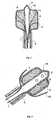
- Fig. 1shows cross section of the device for the TA according to a first embodiment of the invention.
- the deviceincludes a thin hollow element 1, such for instance a needle or a catheter, with a closed tip 2, suitable for penetrating the tissues to be subject to the TA procedure.
- the deviceis provided with an expandable and semipermeable membrane 3, wherein the hollow element 1 is coaxially inserted and sealed.
- the hollow element 1is made of a conductive material and it is connected to a radiofrequency energy generator.
- the hollow element 1is the active electrode of the TA device.
- the hollow element 1is provided with one or more openings 4 circumferentially arranged in proximity to its tip 2.
- the end of the hollow element 1is also surrounded by the membrane 3 that is sealed thereon.
- the residual portion of the hollow element 1can be insulated, for example, by means of an insulating paint or an insulating sheath 5.
- an injection systeminjects a substance 6 through the opening or openings 4 of the hollow element 1 into the membrane 3, the substance 6 expands the membrane 3 thus generating on the tissues a pressure being higher than the atmospheric one, and permeates there-through, thus closely contacting the surrounding tumoral tissues.
- the generatordelivers electromagnetic energy, thus causing ionic turbulence in the zone surrounding the element 1 and thereby resistive heat.
- the transmission of the energy to the tissuesis carried out due the electric conductivity properties of the substance 6, which contacts the hollow element 1.
- the substance 6must be biocompatible and capable of maintaining a low coupling impedance between the active part of the device and the tumoral tissues even at high temperatures. In such a way a continuous energy delivery from the device to the tissues is granted.
- the injection into the tumoral mass of an electrically conductive substancebeing capable of maintaining hydrated the region surrounding the electrode even at very high temperatures and/or maintaining the impedance constantly low during the energy delivery, allows to extend such a delivery for a very long time and thereby to generate thermal lesions having a large size without reaching the dehydration and the carbonization of the same tissues. Thereby it is possible to predict the size of the thermal lesion by setting a suitable time-profile of the power delivery.
- the substance 6is biocompatible, dries or boils at temperatures being higher than the boiling temperature of the tissue liquids, has a viscosity being higher than that of the blood and has an electric conductivity comprised between one tenth and one hundred times the electric conductivity of the tissue liquids.
- the substance 6may be a gel, a hydrogel, a thixotropic hydrogel, an aqueous ionic solution, a suspension having a size of the suspended particles comprised between about 1 ⁇ m and about 1000 ⁇ m, or a mixture of such substances.
- One of the main characteristics of the inventionis that the retaining action of the membrane 3 allows to keep the distribution of the substance 6 through the tissues totally under control, the substance permeating through the membrane 3 reaching the external surface thereof thus closely contacting the surrounding tissues.
- the possibility of exactly controlling the distribution of the substance 6,allows to surely predict the shape of the generated thermal lesion.
- the membrane 3may have any shape, however in the preferred embodiments a cylindrical geometry is used with suitable zones connecting it to the hollow element 1.
- Suitable materials for the manufacturing of the semipermeable membraneare, for example, the biological membranes, or woven or non-woven polymeric materials based on PET, PP, PA or PE.
- Another characteristic of the device according to the present inventionis that due to the effect of the injection of the substance 6 into the membrane 3, the local pressure on the tissues increases over the atmospheric pressure.
- the boiling temperature increase in the tissue liquidsbeing due to the pressure locally exerted by an expandable membrane, allows to deliver more energy to the tissues and thereby to generate thermal lesions having dimensions that are larger than those obtainable with known techniques.
- the pressure inside the membrane 3can be measured, for instance, by means of a pressure transducer and controlled in a close loop in order to grant the maintenance of the pre-set conditions for the whole duration of the procedure.
- a second embodiment of the device for TA with RFis shown according to the present invention.
- the design of the deviceis completely analogous to that of the device shown in Fig. 1 , however this embodiment provides for the use of a cooling circuit being inserted into the hollow element 1, allowing to keep under control the temperature of the hollow element 1 during the treatment.
- the flow of electrical currentgenerates resistive heat and the temperature profile of the heated zone has the maximum values close to the hollow element 1.
- the temperature controlcombined with the use of the substance 6 supports the duration of the TA procedures of and further increases the possibilities of setting the time-profile of the power.
- the cooling circuitis composed of a small diameter canalization 7 being coaxially inserted into the hollow element 1.
- a conventional pumping systemcirculates a cooling substance 8 in the canalization 7, absorbing heat from the end of the element 1 and releasing it by passing, for instance, through a heat exchanger and then returning towards the end of the hollow element 1.
- the arrows 9indicate an hypothetical circulation direction of the cooling substance 8 inside the canalization 7.
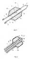
- a third embodiment of the device for the TA with RFis shown according to the present invention.
- the design of the element 1 and of the membrane 3is analogous to that of the previous drawings, however in this case the openings 4 provided in the proximity of the tip 2 of the hollow element 1 have a large size in order to allow the extraction of one or more filiform electrodes 10 in the space comprised between the hollow element 1 and the membrane 3.
- the electrodes 10improve the energy delivery distribution as they increase the electrode surface thus allowing to further increase the efficiency of delivery of electromagnetic energy.
- Fig. 4shows a fourth embodiment of the device for the TA with RF according to the present invention, being analogous to the one shown in Fig. 3 .
- the filiform electrodes 10are extracted from the hollow element 1 at the outside of the membrane 3 and contact the tissues.
- Fig. 5shows a fifth embodiment of the device for TA with RF according to the present invention, using a bipolar technique for the delivery of electromagnetic energy.
- the end of the hollow element 1 enclosed in the membrane 3is divided into an upper zone 11 and a lower zone 12 by interposing a ring 13 being made of an insulating material and having diameter and thickness equal to the hollow element 1.
- the two upper 11 and lower 12 zonesare connected to the two poles of the circuit and form the active electrode and the counter electrode, respectively.
- the substance 6is injected into the membrane 3 through the openings 4 of the hollow element 1 as previously described.
- electromagnetic field linesare generated going from one electrode to the other one and causing, as in the previous cases, ionic turbulence and consequent resistive heat.
- Fig. 6shows a sixth embodiment of the device for the TA according to the present invention of a microwaves type, wherein, in the same way as in the previous embodiments, the hollow element 1 is provided with a membrane 3 and with one or more openings 4 circumferentially arranged in proximity of the tip 2 of the hollow element 1.
- a coaxial cable 14is arranged inside the hollow element 1 , delivering electromagnetic energy in the microwaves range.
- the hollow element 1is formed by materials being transparent to the microwaves in order not to interfere with their propagation through the tissues.
- a further characteristic of the device and the method according to the present inventionis that, once completed the TA procedure, the membrane 3 can be left in situ, that is in the necrotized tissue mass.
- the possibility of leaving the membrane in situleads to a remarkable simplification of the procedure, which only requires the extraction of the hollow element 1 from the patient's body once it is ended. This does not affect the patient's health, as the membrane material is absolutely biocompatible as well as the substance 6 used to expand it.
- connection and release of the membranecould be accomplished by a gluing with a pre-set releasing load, by screwing and unscrewing rotating the catheter body on threaded corresponding profiles, or by snapping.
Landscapes
- Health & Medical Sciences (AREA)
- Surgery (AREA)
- Engineering & Computer Science (AREA)
- Life Sciences & Earth Sciences (AREA)
- Medical Informatics (AREA)
- General Health & Medical Sciences (AREA)
- Nuclear Medicine, Radiotherapy & Molecular Imaging (AREA)
- Plasma & Fusion (AREA)
- Biomedical Technology (AREA)
- Heart & Thoracic Surgery (AREA)
- Physics & Mathematics (AREA)
- Molecular Biology (AREA)
- Animal Behavior & Ethology (AREA)
- Otolaryngology (AREA)
- Public Health (AREA)
- Veterinary Medicine (AREA)
- Medicines That Contain Protein Lipid Enzymes And Other Medicines (AREA)
- Electrotherapy Devices (AREA)
- Surgical Instruments (AREA)
- Pharmaceuticals Containing Other Organic And Inorganic Compounds (AREA)
- Radiation-Therapy Devices (AREA)
Abstract
Description
- The present invention relates to a device and a method for the treatment of tumors by means of thermal ablation (TA) induced by electromagnetic energy, e. g. in the radiofrequencies (RF) or in the microwaves (MW) range, and particularly to a device and a method for the TA which allows to obtain lesions having a large volume and a predictable and controllable shape.
- It is known that the TA procedure induced by electromagnetic energy essentially consist of inserting into a tumoral mass an electrode that, being supplied with electromagnetic energy at a suitable frequency, leads to the generation of heat in the surrounding tumoral tissues, thus causing their coagulative necrosis. The electrode, being generally placed at the end of a needle or a catheter, is percutaneously introduced in the mass of the tumor and it is guided by means of echography or other visualization techniques known in the art. This procedure has proved to be effective for the ablation of tumors of the liver and it has recently been suggested for the ablation of tumors of lung, kidney and other parenchymal organs.
- One of the major problems of this kind of procedure consists in the difficulty of destroying tumoral masses having a diameter that is larger than 3 cm. The main reason is that the energy delivered through the electrode inserted in the tumoral mass can not be indefinitely increased. In fact, if on one hand the delivery of high power allows to increase the size of the thermal lesion, on the other hand it causes a rapid dehydration of the tissues closest to the electrode with the consequent impossibility of delivering further energy to the surrounding tissues.
- Another problem of the known art is that controlling the shape of the generated thermal lesion is not possible, resulting in the risk of generating thermal lesions poorly corresponding to the shape of the tumor.
- Devices and methods for increasing the volume of the thermal lesion in the tumoral mass are already known, consisting of infusing a conductive liquid therein, which transmits energy all around due to its electric conductivity. For instance, patent
US 6.911.019 discloses a catheter provided with an helicoidal needle that is inserted in the tumoral mass in order to create an helicoidal cavity being infused with a conductive liquid. The object is to create a channel with a prescribed shape in order to control the size of the thermal lesion. However, this method has the drawback of generating a thermal lesion having an irregular shape and a volume being difficult to predict due to the uncontrollable distribution of the conductive liquid into the tissues. - In patent application
US 20040006336 a device is disclosed showing a hollow electrode that allows to improve the infusion of the conductive liquid into the tissue. Also this device exhibits the drawback of not allowing the control of the distribution of the conductive liquid into the tissues, that is the size of the zone being subject to the TA. - The same drawback is also present in the device disclosed in
US 2005/096638 relating to a thermal ablation device for the treatment of obesity. In one embodiment, the device comprises an ablation probe including an electrode connected to a hugh frequency electromagnetic energy generator and an expandable membrane suitable for being expanded by a fluid injected therein. The membrane is made of a semipermeable material in order to allow the fluid to leak at a relatively low flow rate thus contacting the tissues surrounding the ablation probe. The fluid is electrically conductive and serves to increase the surface area of the electrode and to evenly distribute heat generated by the electrode across the target tissues. - Object of the present invention is thus to provide a device and a method for the TA being free from the above-mentioned drawbacks, being suitable for increasing the volume of the thermal lesion to the utmost and being suitable for giving it a shape that is as round as possible. Such an object is achieved with the device for TA according to the present invention, whose characteristics are specified in
claim 1. Further characteristics of such a device are specified in the dependent claims. In the subsequent claims the characteristics of the method for TA according to the present invention are specified. - Thanks to the use of a substance being electrically conductive, keeping the tissue hydrated around the active part of the electrode and the impedance of the system constantly low, combined with the use of an expandable membrane, locally pressing the tissues to be treated, it is possible to transfer an adequate power level to the tumoral tissue wherein the electrode is inserted, for a much longer time without being limited by the dehydration of the tissues surrounding the electrode.
- One advantage of the device and the method for the TA according to the present invention, is that the shape and the volume of the generated thermal lesions are regular and predictable in an extremely precise way. In fact the above-mentioned substance is injected inside a semi-permeable and expandable membrane and closely contacts the tissues surrounding the device while remaining enclosed in the known volume of the membrane.
- Another advantage provided by the device and the method for the TA according to the present invention is that the extraction of the device from the thermal lesion is facilitated by leaving the bulkiest part, i.e. the expandable membrane, "in situ" thus remarkably simplifying the operation.
- A further advantage of the device and the method for the TA is that they are usable with electromagnetic energy both in the radiofrequencies and the microwaves range, with little manufacturing differences which will be promptly evident to those skilled in the art.
- This and other advantages of the device for TA according to the present invention will be evident to those skilled in the art from the following detailed description of some embodiments thereof with reference to the annexed drawings wherein:
Figure 1 shows a sectional detailed view of the end of the hollow element of a first embodiment of the device for the TA;Figure 2 shows a sectional detailed view of the end of the hollow element of a second embodiment of the device for the TA;Figure 3 shows a sectional detailed view of the end of the hollow element of a third embodiment of the device for the TA;Figure 4 shows a sectional detailed view of the end of the hollow element of a fourth embodiment of the device for the TA;Figure 5 shows a sectional detailed view of the end of the hollow element of a fifth embodiment of the device for the TA; andFigure 6 shows a sectional detailed view of the end of the hollow element of a sixth embodiment of the device for the TA.Fig. 1 shows cross section of the device for the TA according to a first embodiment of the invention. The device includes a thinhollow element 1, such for instance a needle or a catheter, with a closedtip 2, suitable for penetrating the tissues to be subject to the TA procedure. The device is provided with an expandable andsemipermeable membrane 3, wherein thehollow element 1 is coaxially inserted and sealed. In this particular embodiment, thehollow element 1 is made of a conductive material and it is connected to a radiofrequency energy generator. Thus in this embodiment thehollow element 1 is the active electrode of the TA device. Thehollow element 1 is provided with one ormore openings 4 circumferentially arranged in proximity to itstip 2. The end of thehollow element 1 is also surrounded by themembrane 3 that is sealed thereon. The residual portion of thehollow element 1 can be insulated, for example, by means of an insulating paint or an insulatingsheath 5. Once inserted thehollow element 1 in the tumoral mass, an injection system injects asubstance 6 through the opening oropenings 4 of thehollow element 1 into themembrane 3, thesubstance 6 expands themembrane 3 thus generating on the tissues a pressure being higher than the atmospheric one, and permeates there-through, thus closely contacting the surrounding tumoral tissues. Then the generator delivers electromagnetic energy, thus causing ionic turbulence in the zone surrounding theelement 1 and thereby resistive heat. The transmission of the energy to the tissues is carried out due the electric conductivity properties of thesubstance 6, which contacts thehollow element 1. All the tissues being comprised between the electrodes and the 60°C isotherm undergo a non-reversible coagulative necrosis. Non-reversible damages are associated to temperatures comprised between 46°C and 60°C, whose entity is proportional to the time of exposure.- The
substance 6 must be biocompatible and capable of maintaining a low coupling impedance between the active part of the device and the tumoral tissues even at high temperatures. In such a way a continuous energy delivery from the device to the tissues is granted. In fact, as it may be learnt from patent publicationWO 2007/113866 in the name of the same applicant, the injection into the tumoral mass of an electrically conductive substance, being capable of maintaining hydrated the region surrounding the electrode even at very high temperatures and/or maintaining the impedance constantly low during the energy delivery, allows to extend such a delivery for a very long time and thereby to generate thermal lesions having a large size without reaching the dehydration and the carbonization of the same tissues. Thereby it is possible to predict the size of the thermal lesion by setting a suitable time-profile of the power delivery. - Still in the patent publication
WO 2007/113866 , it may be learnt that thesubstance 6 is biocompatible, dries or boils at temperatures being higher than the boiling temperature of the tissue liquids, has a viscosity being higher than that of the blood and has an electric conductivity comprised between one tenth and one hundred times the electric conductivity of the tissue liquids. Thesubstance 6 may be a gel, a hydrogel, a thixotropic hydrogel, an aqueous ionic solution, a suspension having a size of the suspended particles comprised between about 1 µm and about 1000 µm, or a mixture of such substances. - One of the main characteristics of the invention is that the retaining action of the
membrane 3 allows to keep the distribution of thesubstance 6 through the tissues totally under control, the substance permeating through themembrane 3 reaching the external surface thereof thus closely contacting the surrounding tissues. The possibility of exactly controlling the distribution of thesubstance 6, allows to surely predict the shape of the generated thermal lesion. Themembrane 3 may have any shape, however in the preferred embodiments a cylindrical geometry is used with suitable zones connecting it to thehollow element 1. - Suitable materials for the manufacturing of the semipermeable membrane are, for example, the biological membranes, or woven or non-woven polymeric materials based on PET, PP, PA or PE.
- Another characteristic of the device according to the present invention is that due to the effect of the injection of the
substance 6 into themembrane 3, the local pressure on the tissues increases over the atmospheric pressure. As it may be learnt from a patent publicationWO 2007/113865 in the name of the same applicant, the boiling temperature increase in the tissue liquids, being due to the pressure locally exerted by an expandable membrane, allows to deliver more energy to the tissues and thereby to generate thermal lesions having dimensions that are larger than those obtainable with known techniques. - The pressure inside the
membrane 3 can be measured, for instance, by means of a pressure transducer and controlled in a close loop in order to grant the maintenance of the pre-set conditions for the whole duration of the procedure. - In
Fig. 2 a second embodiment of the device for TA with RF is shown according to the present invention. The design of the device is completely analogous to that of the device shown inFig. 1 , however this embodiment provides for the use of a cooling circuit being inserted into thehollow element 1, allowing to keep under control the temperature of thehollow element 1 during the treatment. In fact, as it is known the flow of electrical current generates resistive heat and the temperature profile of the heated zone has the maximum values close to thehollow element 1. The temperature control combined with the use of thesubstance 6 supports the duration of the TA procedures of and further increases the possibilities of setting the time-profile of the power. In the shown embodiment, the cooling circuit is composed of asmall diameter canalization 7 being coaxially inserted into thehollow element 1. A conventional pumping system circulates a cooling substance 8 in thecanalization 7, absorbing heat from the end of theelement 1 and releasing it by passing, for instance, through a heat exchanger and then returning towards the end of thehollow element 1. The arrows 9 indicate an hypothetical circulation direction of the cooling substance 8 inside thecanalization 7. - In
Fig. 3 a third embodiment of the device for the TA with RF is shown according to the present invention. The design of theelement 1 and of themembrane 3 is analogous to that of the previous drawings, however in this case theopenings 4 provided in the proximity of thetip 2 of thehollow element 1 have a large size in order to allow the extraction of one or morefiliform electrodes 10 in the space comprised between thehollow element 1 and themembrane 3. Theelectrodes 10 improve the energy delivery distribution as they increase the electrode surface thus allowing to further increase the efficiency of delivery of electromagnetic energy. Fig. 4 shows a fourth embodiment of the device for the TA with RF according to the present invention, being analogous to the one shown inFig. 3 . In this case thefiliform electrodes 10 are extracted from thehollow element 1 at the outside of themembrane 3 and contact the tissues. In other embodiments (not shown) it is also possible to combinefiliform electrodes 10 inside and outside themembrane 3.Fig. 5 shows a fifth embodiment of the device for TA with RF according to the present invention, using a bipolar technique for the delivery of electromagnetic energy. The end of thehollow element 1 enclosed in themembrane 3 is divided into anupper zone 11 and alower zone 12 by interposing aring 13 being made of an insulating material and having diameter and thickness equal to thehollow element 1. The two upper 11 and lower 12 zones are connected to the two poles of the circuit and form the active electrode and the counter electrode, respectively. In a TA procedure thesubstance 6 is injected into themembrane 3 through theopenings 4 of thehollow element 1 as previously described. When switching on the generator, electromagnetic field lines are generated going from one electrode to the other one and causing, as in the previous cases, ionic turbulence and consequent resistive heat.Fig. 6 shows a sixth embodiment of the device for the TA according to the present invention of a microwaves type, wherein, in the same way as in the previous embodiments, thehollow element 1 is provided with amembrane 3 and with one ormore openings 4 circumferentially arranged in proximity of thetip 2 of thehollow element 1. In this embodiment, differently from the previous ones, inside the hollow element 1 acoaxial cable 14 is arranged, delivering electromagnetic energy in the microwaves range. In this case thehollow element 1 is formed by materials being transparent to the microwaves in order not to interfere with their propagation through the tissues.- A further characteristic of the device and the method according to the present invention is that, once completed the TA procedure, the
membrane 3 can be left in situ, that is in the necrotized tissue mass. The possibility of leaving the membrane in situ leads to a remarkable simplification of the procedure, which only requires the extraction of thehollow element 1 from the patient's body once it is ended. This does not affect the patient's health, as the membrane material is absolutely biocompatible as well as thesubstance 6 used to expand it. - The detachment of the
hollow element 1 from themembrane 3 occurs in correspondence toconnection areas 15 provided on thehollow element 1 by applying a predetermined load. For instance connection and release of the membrane could be accomplished by a gluing with a pre-set releasing load, by screwing and unscrewing rotating the catheter body on threaded corresponding profiles, or by snapping. - By means of the above-described devices it is possible to perform the TA method according to the present invention, comprising the steps of:
- a. inserting a device into a tumoral mass, being provided with a
hollow element 1 that is tightly inserted into anexpandable membrane 3; - b. pressurizing said
membrane 3 by injecting asubstance 6; and - c. delivering electromagnetic energy at a high frequency in the tumoral mass till the coagulative necrosis of the tissues.
Claims (18)
- A device for the thermal ablation comprising a thin hollow element (1) suitable for being connected to an electromagnetic energy generator at high frequency, an expandable membrane (3) made of biocompatible and semipermeable material, the membrane defining an interior space and being connected to said hollow element (1), and a substance (6) suitable for being injected into said interior space (3) through one or more openings (4) provided on the portion of the hollow element (1) being enclosed in the membrane (3),characterized in that said substance (6) is biocompatible, dries or boils at temperatures higher than the boiling temperature of the tissue liquids, has a viscosity higher than that of the blood and has an electric conductivity comprised between one tenth and one hundred times the electric conductivity of the tissue liquids, the membrane (3) being permeable to the substance (6).
- A device according to claim 1,characterized in that the membrane (3) is made of a biological material.
- A device according to claim 1,characterized in that the membrane (3) is made of a woven or non-woven fabric based on PET, PP, PA and/or PE.
- A device according to one of claims 1 to 3,characterized in that the substance (6) is in the form of a gel.
- A device according to one of claims 1 to 3,characterized in that the substance (6) is in the form of a hydrogel.
- A device according to one of claims 1 to 3,characterized in that the substance (6) is in the form of a thixotropic hydrogel.
- A device according to one of claims 1 to 3,characterized in that the substance (6) is an aqueous ionic solution.
- A device according to one of claims 1 to 3,characterized in that the substance (6) is in the form of a suspension having a suspended particles size comprised between about 1 µm and about 1000 µm.
- A device according to one of claims 1 to 3,characterized in that the substance (6) is a mixture of two or more of any of the substances (6) according to claims 4, 5, 6, 7 or 8.
- A device according to one of the preceding claims,characterized by further comprising transducers suitable for measuring the pressure inside the membrane (3).
- A device according to one of the preceding claims,characterized by further comprising a cooling circuit formed of a small diameter canalization (7) coaxially inserted into the hollow element (1) and suitable for circulating a cooling substance (8).
- A device according to one of the preceding claims,characterized by further comprising one or more filiform electrodes (10) extractable from the hollow element (1) through said openings (4) provided on the portion of the hollow element (1) connected to said membrane (3).
- A device according to one of the preceding claims,characterized by further comprising one or more filiform electrodes (10) extractable from the hollow element (1) at the outside of the membrane (3).
- A device according to one of claims 1 to 11,characterized in that the end of the hollow element (1) is divided in an upper zone (11) and a lower zone (12) by a ring (13) made of an insulating material and having diameter and thickness equal to those of the hollow element (1), said upper (11) and lower (12) zones being respectively connected to the two poles of the circuit and said membrane (3) being coaxially assembled on the hollow element (1) and sealed on the ring (13).
- A device according to one of the preceding claims,characterized in that the membrane (3) is detachable from the hollow element (1) in correspondence to connecting areas (15) provided on the hollow element (1).
- A device according to claim 15,characterized in that the connecting areas (15) between the membrane (3) and the hollow element (1) are made of a gluing having a pre-set releasing load.
- A device according to claim 15,characterized in that the connecting areas (15) between the membrane (3) and the hollow element (1) are made of corresponding threaded profiles.
- A device according to claim 15,characterized in that the connecting areas (15) between the membrane (3) and the hollow element (1) are made of a snapping mechanism.
Applications Claiming Priority (1)
| Application Number | Priority Date | Filing Date | Title |
|---|---|---|---|
| PCT/IT2006/000211WO2007113867A1 (en) | 2006-03-31 | 2006-03-31 | Device and method for the controlled thermal ablation of tumors by means of high-frequency electromagnetic energy |
Publications (2)
| Publication Number | Publication Date |
|---|---|
| EP2001384A1 EP2001384A1 (en) | 2008-12-17 |
| EP2001384B1true EP2001384B1 (en) | 2009-08-26 |
Family
ID=37441566
Family Applications (1)
| Application Number | Title | Priority Date | Filing Date |
|---|---|---|---|
| EP06745253ANot-in-forceEP2001384B1 (en) | 2006-03-31 | 2006-03-31 | Device for the controlled thermal ablation of tumors by means of high-frequency electromagnetic energy |
Country Status (5)
| Country | Link |
|---|---|
| US (1) | US20090306654A1 (en) |
| EP (1) | EP2001384B1 (en) |
| AT (1) | ATE440558T1 (en) |
| DE (1) | DE602006008832D1 (en) |
| WO (1) | WO2007113867A1 (en) |
Families Citing this family (25)
| Publication number | Priority date | Publication date | Assignee | Title |
|---|---|---|---|---|
| US9662163B2 (en) | 2008-10-21 | 2017-05-30 | Hermes Innovations Llc | Endometrial ablation devices and systems |
| US8821486B2 (en) | 2009-11-13 | 2014-09-02 | Hermes Innovations, LLC | Tissue ablation systems and methods |
| US8197477B2 (en) | 2008-10-21 | 2012-06-12 | Hermes Innovations Llc | Tissue ablation methods |
| US8197476B2 (en) | 2008-10-21 | 2012-06-12 | Hermes Innovations Llc | Tissue ablation systems |
| US8540708B2 (en) | 2008-10-21 | 2013-09-24 | Hermes Innovations Llc | Endometrial ablation method |
| US8500732B2 (en) | 2008-10-21 | 2013-08-06 | Hermes Innovations Llc | Endometrial ablation devices and systems |
| US8382753B2 (en) | 2008-10-21 | 2013-02-26 | Hermes Innovations, LLC | Tissue ablation methods |
| US8715278B2 (en) | 2009-11-11 | 2014-05-06 | Minerva Surgical, Inc. | System for endometrial ablation utilizing radio frequency |
| US8529562B2 (en) | 2009-11-13 | 2013-09-10 | Minerva Surgical, Inc | Systems and methods for endometrial ablation |
| US11896282B2 (en) | 2009-11-13 | 2024-02-13 | Hermes Innovations Llc | Tissue ablation systems and method |
| US9289257B2 (en) | 2009-11-13 | 2016-03-22 | Minerva Surgical, Inc. | Methods and systems for endometrial ablation utilizing radio frequency |
| US8956348B2 (en) | 2010-07-21 | 2015-02-17 | Minerva Surgical, Inc. | Methods and systems for endometrial ablation |
| US9510897B2 (en) | 2010-11-05 | 2016-12-06 | Hermes Innovations Llc | RF-electrode surface and method of fabrication |
| US9764160B2 (en) | 2011-12-27 | 2017-09-19 | HJ Laboratories, LLC | Reducing absorption of radiation by healthy cells from an external radiation source |
| US10080907B1 (en) | 2012-10-26 | 2018-09-25 | University Of South Florida | Systems and methods for controlling the spatial distribution of an electromagnetic field |
| US9901394B2 (en) | 2013-04-04 | 2018-02-27 | Hermes Innovations Llc | Medical ablation system and method of making |
| US9649125B2 (en) | 2013-10-15 | 2017-05-16 | Hermes Innovations Llc | Laparoscopic device |
| US10492856B2 (en) | 2015-01-26 | 2019-12-03 | Hermes Innovations Llc | Surgical fluid management system and method of use |
| CN107708591B (en) | 2015-04-29 | 2020-09-29 | 席勒斯科技有限公司 | Medical ablation device and method of use |
| US10052149B2 (en) | 2016-01-20 | 2018-08-21 | RELIGN Corporation | Arthroscopic devices and methods |
| CN109561899A (en) | 2016-04-22 | 2019-04-02 | 锐凌公司 | Arthroscope device and method |
| CN109661209A (en) | 2016-07-01 | 2019-04-19 | 锐凌公司 | Arthroscope device and method |
| EP3522807B1 (en) | 2016-10-04 | 2025-07-09 | Avent, Inc. | Cooled rf probes |
| WO2019191071A1 (en)* | 2018-03-27 | 2019-10-03 | Boston Scientific Scimed, Inc. | Medical devices and related methods |
| US11554214B2 (en) | 2019-06-26 | 2023-01-17 | Meditrina, Inc. | Fluid management system |
Family Cites Families (16)
| Publication number | Priority date | Publication date | Assignee | Title |
|---|---|---|---|---|
| DE2124684A1 (en)* | 1971-05-18 | 1972-11-30 | Stadelmann W | Puncture electrode |
| US5571088A (en)* | 1993-07-01 | 1996-11-05 | Boston Scientific Corporation | Ablation catheters |
| US5807395A (en)* | 1993-08-27 | 1998-09-15 | Medtronic, Inc. | Method and apparatus for RF ablation and hyperthermia |
| US5683384A (en)* | 1993-11-08 | 1997-11-04 | Zomed | Multiple antenna ablation apparatus |
| US6733515B1 (en)* | 1997-03-12 | 2004-05-11 | Neomend, Inc. | Universal introducer |
| US6273886B1 (en)* | 1998-02-19 | 2001-08-14 | Curon Medical, Inc. | Integrated tissue heating and cooling apparatus |
| US6537248B2 (en)* | 1998-07-07 | 2003-03-25 | Medtronic, Inc. | Helical needle apparatus for creating a virtual electrode used for the ablation of tissue |
| US7819861B2 (en)* | 2001-05-26 | 2010-10-26 | Nuortho Surgical, Inc. | Methods for electrosurgical electrolysis |
| US7422586B2 (en)* | 2001-02-28 | 2008-09-09 | Angiodynamics, Inc. | Tissue surface treatment apparatus and method |
| US20060155261A1 (en)* | 2001-09-19 | 2006-07-13 | Curon Medical, Inc. | Systems and methods for treating tissue regions of the body |
| JP3607231B2 (en)* | 2001-09-28 | 2005-01-05 | 有限会社日本エレクテル | High frequency heating balloon catheter |
| US20040006336A1 (en) | 2002-07-02 | 2004-01-08 | Scimed Life Systems, Inc. | Apparatus and method for RF ablation into conductive fluid-infused tissue |
| US6847848B2 (en)* | 2003-01-07 | 2005-01-25 | Mmtc, Inc | Inflatable balloon catheter structural designs and methods for treating diseased tissue of a patient |
| US20040230316A1 (en)* | 2003-05-12 | 2004-11-18 | Iulian Cioanta | Method for treating the prostate and inhibiting obstruction of the prostatic urethra using biodegradable stents |
| US7282050B2 (en)* | 2003-10-31 | 2007-10-16 | Medtronic, Inc. | Ablation of exterior of stomach to treat obesity |
| WO2006031541A1 (en)* | 2004-09-09 | 2006-03-23 | Vnus Medical Technologies, Inc. | Methods and apparatus for treatment of hollow anatomical structures |
- 2006
- 2006-03-31WOPCT/IT2006/000211patent/WO2007113867A1/enactiveApplication Filing
- 2006-03-31USUS12/295,218patent/US20090306654A1/ennot_activeAbandoned
- 2006-03-31EPEP06745253Apatent/EP2001384B1/ennot_activeNot-in-force
- 2006-03-31ATAT06745253Tpatent/ATE440558T1/ennot_activeIP Right Cessation
- 2006-03-31DEDE602006008832Tpatent/DE602006008832D1/enactiveActive
Also Published As
| Publication number | Publication date |
|---|---|
| WO2007113867A1 (en) | 2007-10-11 |
| ATE440558T1 (en) | 2009-09-15 |
| DE602006008832D1 (en) | 2009-10-08 |
| EP2001384A1 (en) | 2008-12-17 |
| US20090306654A1 (en) | 2009-12-10 |
Similar Documents
| Publication | Publication Date | Title |
|---|---|---|
| EP2001384B1 (en) | Device for the controlled thermal ablation of tumors by means of high-frequency electromagnetic energy | |
| US20100298821A1 (en) | Device and method for the thermal ablation of tumors by means of high-frequency electromagnetic energy under overpressure conditions | |
| US11950829B2 (en) | Methods and devices for use of degassed fluids with fluid enhanced ablation devices | |
| CN111615371B (en) | Enhanced needle array and treatment for tumor ablation | |
| EP1850779B1 (en) | Electro-surgical needle apparatus | |
| WO2007113866A1 (en) | Device and method for the thermal ablation of tumors by means of high-frequency electromagnetic energy | |
| EP1639956B1 (en) | Arrangement for therapy of tumours | |
| RU2317793C1 (en) | Method and device for high-temperature destroy of biological tissue | |
| JP2002165890A (en) | Internal local heating device |
Legal Events
| Date | Code | Title | Description |
|---|---|---|---|
| PUAI | Public reference made under article 153(3) epc to a published international application that has entered the european phase | Free format text:ORIGINAL CODE: 0009012 | |
| 17P | Request for examination filed | Effective date:20081006 | |
| AK | Designated contracting states | Kind code of ref document:A1 Designated state(s):AT BE BG CH CY CZ DE DK EE ES FI FR GB GR HU IE IS IT LI LT LU LV MC NL PL PT RO SE SI SK TR | |
| GRAP | Despatch of communication of intention to grant a patent | Free format text:ORIGINAL CODE: EPIDOSNIGR1 | |
| RTI1 | Title (correction) | Free format text:DEVICE FOR THE CONTROLLED THERMAL ABLATION OF TUMORS BY MEANS OF HIGH-FREQUENCY ELECTROMAGNETIC ENERGY | |
| GRAS | Grant fee paid | Free format text:ORIGINAL CODE: EPIDOSNIGR3 | |
| GRAA | (expected) grant | Free format text:ORIGINAL CODE: 0009210 | |
| AK | Designated contracting states | Kind code of ref document:B1 Designated state(s):AT BE BG CH CY CZ DE DK EE ES FI FR GB GR HU IE IS IT LI LT LU LV MC NL PL PT RO SE SI SK TR | |
| REG | Reference to a national code | Ref country code:GB Ref legal event code:FG4D | |
| REG | Reference to a national code | Ref country code:CH Ref legal event code:EP | |
| REG | Reference to a national code | Ref country code:IE Ref legal event code:FG4D | |
| REF | Corresponds to: | Ref document number:602006008832 Country of ref document:DE Date of ref document:20091008 Kind code of ref document:P | |
| LTIE | Lt: invalidation of european patent or patent extension | Effective date:20090826 | |
| PG25 | Lapsed in a contracting state [announced via postgrant information from national office to epo] | Ref country code:FI Free format text:LAPSE BECAUSE OF FAILURE TO SUBMIT A TRANSLATION OF THE DESCRIPTION OR TO PAY THE FEE WITHIN THE PRESCRIBED TIME-LIMIT Effective date:20090826 Ref country code:AT Free format text:LAPSE BECAUSE OF FAILURE TO SUBMIT A TRANSLATION OF THE DESCRIPTION OR TO PAY THE FEE WITHIN THE PRESCRIBED TIME-LIMIT Effective date:20090826 Ref country code:LT Free format text:LAPSE BECAUSE OF FAILURE TO SUBMIT A TRANSLATION OF THE DESCRIPTION OR TO PAY THE FEE WITHIN THE PRESCRIBED TIME-LIMIT Effective date:20090826 Ref country code:IS Free format text:LAPSE BECAUSE OF FAILURE TO SUBMIT A TRANSLATION OF THE DESCRIPTION OR TO PAY THE FEE WITHIN THE PRESCRIBED TIME-LIMIT Effective date:20091226 Ref country code:SE Free format text:LAPSE BECAUSE OF FAILURE TO SUBMIT A TRANSLATION OF THE DESCRIPTION OR TO PAY THE FEE WITHIN THE PRESCRIBED TIME-LIMIT Effective date:20090826 | |
| NLV1 | Nl: lapsed or annulled due to failure to fulfill the requirements of art. 29p and 29m of the patents act | ||
| PG25 | Lapsed in a contracting state [announced via postgrant information from national office to epo] | Ref country code:LV Free format text:LAPSE BECAUSE OF FAILURE TO SUBMIT A TRANSLATION OF THE DESCRIPTION OR TO PAY THE FEE WITHIN THE PRESCRIBED TIME-LIMIT Effective date:20090826 Ref country code:PL Free format text:LAPSE BECAUSE OF FAILURE TO SUBMIT A TRANSLATION OF THE DESCRIPTION OR TO PAY THE FEE WITHIN THE PRESCRIBED TIME-LIMIT Effective date:20090826 Ref country code:SI Free format text:LAPSE BECAUSE OF FAILURE TO SUBMIT A TRANSLATION OF THE DESCRIPTION OR TO PAY THE FEE WITHIN THE PRESCRIBED TIME-LIMIT Effective date:20090826 Ref country code:NL Free format text:LAPSE BECAUSE OF FAILURE TO SUBMIT A TRANSLATION OF THE DESCRIPTION OR TO PAY THE FEE WITHIN THE PRESCRIBED TIME-LIMIT Effective date:20090826 | |
| PG25 | Lapsed in a contracting state [announced via postgrant information from national office to epo] | Ref country code:BG Free format text:LAPSE BECAUSE OF FAILURE TO SUBMIT A TRANSLATION OF THE DESCRIPTION OR TO PAY THE FEE WITHIN THE PRESCRIBED TIME-LIMIT Effective date:20091126 Ref country code:PT Free format text:LAPSE BECAUSE OF FAILURE TO SUBMIT A TRANSLATION OF THE DESCRIPTION OR TO PAY THE FEE WITHIN THE PRESCRIBED TIME-LIMIT Effective date:20091228 Ref country code:CY Free format text:LAPSE BECAUSE OF FAILURE TO SUBMIT A TRANSLATION OF THE DESCRIPTION OR TO PAY THE FEE WITHIN THE PRESCRIBED TIME-LIMIT Effective date:20090826 | |
| PG25 | Lapsed in a contracting state [announced via postgrant information from national office to epo] | Ref country code:RO Free format text:LAPSE BECAUSE OF FAILURE TO SUBMIT A TRANSLATION OF THE DESCRIPTION OR TO PAY THE FEE WITHIN THE PRESCRIBED TIME-LIMIT Effective date:20090826 Ref country code:ES Free format text:LAPSE BECAUSE OF FAILURE TO SUBMIT A TRANSLATION OF THE DESCRIPTION OR TO PAY THE FEE WITHIN THE PRESCRIBED TIME-LIMIT Effective date:20091207 Ref country code:DK Free format text:LAPSE BECAUSE OF FAILURE TO SUBMIT A TRANSLATION OF THE DESCRIPTION OR TO PAY THE FEE WITHIN THE PRESCRIBED TIME-LIMIT Effective date:20090826 Ref country code:CZ Free format text:LAPSE BECAUSE OF FAILURE TO SUBMIT A TRANSLATION OF THE DESCRIPTION OR TO PAY THE FEE WITHIN THE PRESCRIBED TIME-LIMIT Effective date:20090826 Ref country code:EE Free format text:LAPSE BECAUSE OF FAILURE TO SUBMIT A TRANSLATION OF THE DESCRIPTION OR TO PAY THE FEE WITHIN THE PRESCRIBED TIME-LIMIT Effective date:20090826 | |
| PG25 | Lapsed in a contracting state [announced via postgrant information from national office to epo] | Ref country code:SK Free format text:LAPSE BECAUSE OF FAILURE TO SUBMIT A TRANSLATION OF THE DESCRIPTION OR TO PAY THE FEE WITHIN THE PRESCRIBED TIME-LIMIT Effective date:20090826 | |
| PG25 | Lapsed in a contracting state [announced via postgrant information from national office to epo] | Ref country code:BE Free format text:LAPSE BECAUSE OF FAILURE TO SUBMIT A TRANSLATION OF THE DESCRIPTION OR TO PAY THE FEE WITHIN THE PRESCRIBED TIME-LIMIT Effective date:20090826 | |
| PLBE | No opposition filed within time limit | Free format text:ORIGINAL CODE: 0009261 | |
| STAA | Information on the status of an ep patent application or granted ep patent | Free format text:STATUS: NO OPPOSITION FILED WITHIN TIME LIMIT | |
| 26N | No opposition filed | Effective date:20100527 | |
| PG25 | Lapsed in a contracting state [announced via postgrant information from national office to epo] | Ref country code:GR Free format text:LAPSE BECAUSE OF FAILURE TO SUBMIT A TRANSLATION OF THE DESCRIPTION OR TO PAY THE FEE WITHIN THE PRESCRIBED TIME-LIMIT Effective date:20091127 Ref country code:MC Free format text:LAPSE BECAUSE OF NON-PAYMENT OF DUE FEES Effective date:20100331 | |
| REG | Reference to a national code | Ref country code:CH Ref legal event code:PL | |
| PG25 | Lapsed in a contracting state [announced via postgrant information from national office to epo] | Ref country code:IE Free format text:LAPSE BECAUSE OF NON-PAYMENT OF DUE FEES Effective date:20100331 | |
| PG25 | Lapsed in a contracting state [announced via postgrant information from national office to epo] | Ref country code:CH Free format text:LAPSE BECAUSE OF NON-PAYMENT OF DUE FEES Effective date:20100331 Ref country code:LI Free format text:LAPSE BECAUSE OF NON-PAYMENT OF DUE FEES Effective date:20100331 | |
| PGFP | Annual fee paid to national office [announced via postgrant information from national office to epo] | Ref country code:DE Payment date:20110413 Year of fee payment:6 Ref country code:FR Payment date:20110421 Year of fee payment:6 Ref country code:GB Payment date:20110330 Year of fee payment:6 | |
| PGFP | Annual fee paid to national office [announced via postgrant information from national office to epo] | Ref country code:IT Payment date:20110329 Year of fee payment:6 | |
| PG25 | Lapsed in a contracting state [announced via postgrant information from national office to epo] | Ref country code:HU Free format text:LAPSE BECAUSE OF FAILURE TO SUBMIT A TRANSLATION OF THE DESCRIPTION OR TO PAY THE FEE WITHIN THE PRESCRIBED TIME-LIMIT Effective date:20100227 Ref country code:LU Free format text:LAPSE BECAUSE OF NON-PAYMENT OF DUE FEES Effective date:20100331 | |
| PG25 | Lapsed in a contracting state [announced via postgrant information from national office to epo] | Ref country code:TR Free format text:LAPSE BECAUSE OF FAILURE TO SUBMIT A TRANSLATION OF THE DESCRIPTION OR TO PAY THE FEE WITHIN THE PRESCRIBED TIME-LIMIT Effective date:20090826 | |
| GBPC | Gb: european patent ceased through non-payment of renewal fee | Effective date:20120331 | |
| REG | Reference to a national code | Ref country code:FR Ref legal event code:ST Effective date:20121130 | |
| REG | Reference to a national code | Ref country code:DE Ref legal event code:R119 Ref document number:602006008832 Country of ref document:DE Effective date:20121002 | |
| PG25 | Lapsed in a contracting state [announced via postgrant information from national office to epo] | Ref country code:FR Free format text:LAPSE BECAUSE OF NON-PAYMENT OF DUE FEES Effective date:20120402 Ref country code:GB Free format text:LAPSE BECAUSE OF NON-PAYMENT OF DUE FEES Effective date:20120331 | |
| PG25 | Lapsed in a contracting state [announced via postgrant information from national office to epo] | Ref country code:IT Free format text:LAPSE BECAUSE OF NON-PAYMENT OF DUE FEES Effective date:20120331 | |
| PG25 | Lapsed in a contracting state [announced via postgrant information from national office to epo] | Ref country code:DE Free format text:LAPSE BECAUSE OF NON-PAYMENT OF DUE FEES Effective date:20121002 |