EP2000670B1 - Control valve for variable displacement compressor - Google Patents
Control valve for variable displacement compressorDownload PDFInfo
- Publication number
- EP2000670B1 EP2000670B1EP07707774.1AEP07707774AEP2000670B1EP 2000670 B1EP2000670 B1EP 2000670B1EP 07707774 AEP07707774 AEP 07707774AEP 2000670 B1EP2000670 B1EP 2000670B1
- Authority
- EP
- European Patent Office
- Prior art keywords
- valve
- pressure
- compressor
- control valve
- variable displacement
- Prior art date
- Legal status (The legal status is an assumption and is not a legal conclusion. Google has not performed a legal analysis and makes no representation as to the accuracy of the status listed.)
- Active
Links
- 238000006073displacement reactionMethods0.000titleclaimsdescription43
- 239000012530fluidSubstances0.000claimsdescription6
- 230000005489elastic deformationEffects0.000claimsdescription2
- 239000003507refrigerantSubstances0.000description24
- XEEYBQQBJWHFJM-UHFFFAOYSA-NIronChemical group[Fe]XEEYBQQBJWHFJM-UHFFFAOYSA-N0.000description8
- 238000004378air conditioningMethods0.000description6
- 238000001816coolingMethods0.000description5
- 230000007423decreaseEffects0.000description5
- 239000007788liquidSubstances0.000description3
- 230000000717retained effectEffects0.000description3
- 230000002093peripheral effectEffects0.000description2
- 238000005057refrigerationMethods0.000description2
- 238000007792additionMethods0.000description1
- 230000008602contractionEffects0.000description1
- 230000003247decreasing effectEffects0.000description1
- 238000001704evaporationMethods0.000description1
- 230000008020evaporationEffects0.000description1
- 230000014759maintenance of locationEffects0.000description1
- 238000012986modificationMethods0.000description1
- 230000004048modificationEffects0.000description1
Images


Classifications
- F—MECHANICAL ENGINEERING; LIGHTING; HEATING; WEAPONS; BLASTING
- F04—POSITIVE - DISPLACEMENT MACHINES FOR LIQUIDS; PUMPS FOR LIQUIDS OR ELASTIC FLUIDS
- F04B—POSITIVE-DISPLACEMENT MACHINES FOR LIQUIDS; PUMPS
- F04B27/00—Multi-cylinder pumps specially adapted for elastic fluids and characterised by number or arrangement of cylinders
- F04B27/08—Multi-cylinder pumps specially adapted for elastic fluids and characterised by number or arrangement of cylinders having cylinders coaxial with, or parallel or inclined to, main shaft axis
- F04B27/14—Control
- F04B27/16—Control of pumps with stationary cylinders
- F04B27/18—Control of pumps with stationary cylinders by varying the relative positions of a swash plate and a cylinder block
- F04B27/1804—Controlled by crankcase pressure
- F04B2027/1822—Valve-controlled fluid connection
- F04B2027/1827—Valve-controlled fluid connection between crankcase and discharge chamber
- F—MECHANICAL ENGINEERING; LIGHTING; HEATING; WEAPONS; BLASTING
- F04—POSITIVE - DISPLACEMENT MACHINES FOR LIQUIDS; PUMPS FOR LIQUIDS OR ELASTIC FLUIDS
- F04B—POSITIVE-DISPLACEMENT MACHINES FOR LIQUIDS; PUMPS
- F04B27/00—Multi-cylinder pumps specially adapted for elastic fluids and characterised by number or arrangement of cylinders
- F04B27/08—Multi-cylinder pumps specially adapted for elastic fluids and characterised by number or arrangement of cylinders having cylinders coaxial with, or parallel or inclined to, main shaft axis
- F04B27/14—Control
- F04B27/16—Control of pumps with stationary cylinders
- F04B27/18—Control of pumps with stationary cylinders by varying the relative positions of a swash plate and a cylinder block
- F04B27/1804—Controlled by crankcase pressure
- F04B2027/184—Valve controlling parameter
- F04B2027/185—Discharge pressure
- F—MECHANICAL ENGINEERING; LIGHTING; HEATING; WEAPONS; BLASTING
- F04—POSITIVE - DISPLACEMENT MACHINES FOR LIQUIDS; PUMPS FOR LIQUIDS OR ELASTIC FLUIDS
- F04B—POSITIVE-DISPLACEMENT MACHINES FOR LIQUIDS; PUMPS
- F04B27/00—Multi-cylinder pumps specially adapted for elastic fluids and characterised by number or arrangement of cylinders
- F04B27/08—Multi-cylinder pumps specially adapted for elastic fluids and characterised by number or arrangement of cylinders having cylinders coaxial with, or parallel or inclined to, main shaft axis
- F04B27/14—Control
- F04B27/16—Control of pumps with stationary cylinders
- F04B27/18—Control of pumps with stationary cylinders by varying the relative positions of a swash plate and a cylinder block
- F04B27/1804—Controlled by crankcase pressure
- F04B2027/184—Valve controlling parameter
- F04B2027/1854—External parameters
- F—MECHANICAL ENGINEERING; LIGHTING; HEATING; WEAPONS; BLASTING
- F04—POSITIVE - DISPLACEMENT MACHINES FOR LIQUIDS; PUMPS FOR LIQUIDS OR ELASTIC FLUIDS
- F04B—POSITIVE-DISPLACEMENT MACHINES FOR LIQUIDS; PUMPS
- F04B27/00—Multi-cylinder pumps specially adapted for elastic fluids and characterised by number or arrangement of cylinders
- F04B27/08—Multi-cylinder pumps specially adapted for elastic fluids and characterised by number or arrangement of cylinders having cylinders coaxial with, or parallel or inclined to, main shaft axis
- F04B27/14—Control
- F04B27/16—Control of pumps with stationary cylinders
- F04B27/18—Control of pumps with stationary cylinders by varying the relative positions of a swash plate and a cylinder block
- F04B27/1804—Controlled by crankcase pressure
- F04B2027/184—Valve controlling parameter
- F04B2027/1859—Suction pressure
Definitions
- the present inventionrelates to a control valve for a variable displacement compressor provided with a pressure sensing section, a solenoid section, and a valve section composed of a valve element that is provided to a movement member, wherein the internal pressure of the compressor is adjusted by the degree of opening of the valve element, and the discharge displacement is varied.
- a control valve for a variable displacement compressor that is used to compress the refrigerant of an automobile air conditioning deviceis known as an example of a control valve having a pressure sensing section that applies an urging force to a movement member according to a pressure introduced to the pressure sensing section, wherein the movement member is moved by the urging force to adjust the degree of valve opening (see Patent Document 1).
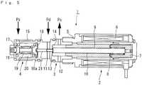
- This control valveuses a bellows assembly in the pressure sensing section, and FIG. 5 is a schematic sectional view showing this type of control valve for a variable displacement compressor.
- the control valve 1is composed of a solenoid section 2, a valve section 3, and a bellows assembly 4.
- the solenoid section 2is disposed at one end of a cylindrical valve body 5, magnetic force is generated by applying an electrical current to a coil 6, a movable iron core 7 is moved against a spring 8 toward a fixed iron core 9 disposed to the left, and an urging force proportional to the square of the current value is applied to a valve rod 10.
- the bellows assembly 4is provided to a pressure sensing chamber 16 composed of a case 15 and the valve body 5, and suction pressure Ps of the compressor acts on the pressure sensing chamber 16.
- the bellows assembly 4has a bellows 19 that is retained at both ends by holders 17, 18 so as to be able to expand and contract, a spring 20 extends between the holders, and a connecting rod 21 in contact with and connected to both members is disposed between the holder 18 and the left end 10a of the valve rod 10. Consequently, the bellows 19 is expanded and contracted by the change in the suction pressure Ps introduced to the pressure sensing chamber 16, the urging force applied to the valve rod 10 changes, and the degree of valve opening is made variable.
- EP 1 388 719 A2relates to an air conditioning system.
- the air conditioning systemincludes a variable displacement compressor under flow rate control by a proportional variable orifice flow rate control solenoid valve in a discharge-side flow passage, and a constant differential pressure valve controlling a differential pressure (PdH - PdL) across the variable orifice, developed depending on a flow rate Qd to a constant level, and a normal charge type expansion valve.
- the expansion valvealways maintains the refrigerant at the evaporator outlet in a superheated state. Even during low load operation, high cooling efficiency is maintained.
- the proportional flow rate control solenoid valvecontrols in response to an external signal a minimum flow. This prevents an oil shortage during low load operation.
- control valve 1 in Patent Document 1is configured so that the suction pressure Ps acts on the bellows 19 provided to the pressure sensing chamber 16 while, on the other hand, the discharge pressure Pd is introduced from the port 11 of the valve body 5 adjacent to the pressure sensing chamber 16, and the communication between the pressure sensing chamber 16 and the port 11 is nearly blocked by the connecting rod 21.
- the blockageis not necessarily complete, and the refrigerant gas moves from the gap between the connecting rod 21 and the valve body 5 and leaks from the discharge pressure Pd side to the suction pressure Ps side, resulting in reduced efficiency.
- a ring sealmay be used in the connecting rod 21 to block communication between the pressure sensing chamber 16 and the port 11.
- sliding resistance created by the ring sealis applied as the connecting rod 21 moves in conjunction with the movement of the movement member, the valve opening position cannot be reliably attained by the movement member, and the correct suction pressure that corresponds to the solenoid thrust is difficult to maintain.
- the present inventionwas developed in view of such drawbacks, and an object of the present invention is to provide a control valve for a variable displacement compressor whereby sliding resistance that accompanies valve movement can be reduced as much as possible, the rate of air flow can be stably and accurately adjusted, and the correct suction pressure that corresponds to solenoid thrust can be maintained.
- the control valve for a variable displacement compressorfor solving the abovementioned problems is a valve comprising a pressure sensing section, a solenoid section, and a valve section composed of a valve element that is provided to a movement member, wherein an internal pressure of the compressor is adjusted by a degree of opening of the valve element, and a discharge displacement is varied;
- the control valve for a variable displacement compressorbeing characterized in that a discharge pressure of the compressor introduced to the pressure sensing section applies an urging force to the movement member;
- the solenoid sectionapplies, in cooperation with the urging force, an urging force to the movement member in accordance with an input signal;
- a degree of opening of the valve elementis set in accordance with a position of the movement member; a rate of air flow of a communicating channel for communicating a compressor inner chamber with a discharge pressure region of the compressor is adjusted; a suction pressure of the compressor is introduced to the control valve to apply an urging force to the movement member; and communication between a fluid having the discharge pressure introduced
- communication between the fluid having the discharge pressure of the compressor that is introduced to the pressure sensing section, and the fluid having the suction pressure of the compressor that is introduced to the control valveis blocked without the use of a seal member or the like by contact of the movement member and an expanding and contracting member constituting the pressure sensing section. Sliding resistance that accompanies movement of the movement member can therefore be eliminated, the flow rate of air via the communicating channel can be stably and accurately adjusted, and the movement member can be prevented from moving in the valve closing direction in response to an increase in discharge pressure when the control valve is not performing control.
- the control valve for a variable displacement compressor according to a second aspect of the present inventionis the control valve for a variable displacement compressor according to the first aspect, characterized in that a sealed chamber acted on by the suction pressure of the compressor is formed in a portion of contact between the expanding and contracting member and the movement member.
- forming a sealed chamber acted on by the suction pressure of the compressor in the portion of contact between the expanding and contracting member and the movement membermakes it possible to maintain seal properties during control as well as valve opening retention properties during non-control through the use of an extremely simple control valve structure.
- FIG. 1is a control flowchart showing the cooling cycle of the variable displacement compressor in an example of the present invention
- FIG. 2is a sectional view showing the control valve for a variable displacement compressor used in FIG. 1
- FIG. 3is an enlarged sectional view showing the pressure sensing chamber
- FIG. 4is a schematic view showing the state of balance of urging forces applied to the valve rod.
- the control valve for a variable displacement compressoris used to control the output of a variable displacement compressor used to compress the refrigerant of a car air conditioner or other automobile air conditioning device, for example, and the functions in the refrigeration cycle of this control valve will be described based on FIG. 1 .
- the refrigeration cycle shown in FIG. 1The refrigeration cycle shown in FIG.
- a control valve 28is configured so as to control the discharge displacement of the variable displacement compressor 20 in accordance with the cooling load.
- a temperature sensor 30is disposed in the vicinity of the evaporator 22, and temperature information of the evaporator 22 is sent as an input signal to a control device 32.
- Vehicle interior temperature information Y or setting information X from a temperature setting device 34 for specifying the temperature of the vehicle cabinis inputted as an input signal to the control device 32, and an output signal Z having the optimum value based on the input signals is computed and outputted to the control valve 28.
- a portion (discharge pressure region) of the refrigerant gas at the discharge pressure Pd discharged from the variable displacement compressor 20passes through the control valve 28 and flows into the inside chamber of the variable displacement compressor 20.
- the operation of the control valve 28will be described in detail hereinafter.
- the degree of opening of the control valve 28varies according to the size of the signal, and the flow rate of refrigerant gas that flows into the inside chamber (crank case chamber) of the variable displacement compressor 20 is adjusted by the degree of valve opening.
- variable rotary swash plate compressorfor example, in which the discharge capacity can be varied according to the size of the pressure Pc of the inside chamber, is used as the variable displacement compressor 20.
- the chamber pressure of the variable displacement compressor 20is communicated with the suction side of the compressor via an aperture or other limiting device, and when the degree of opening of the control valve 28 is large and the flow rate of refrigerant gas increases, the chamber pressure Pc in a state substantially equal to the suction pressure Ps increases, the swash plate stands up, and the discharge quantity of the compressor decreases.
- the degree of opening of the control valve 28is small, the chamber pressure Pc decreases, the swash plate is tilted, and the discharge quantity of the compressor increases.
- the configuration in which the discharge quantity is varied by the change in chamber pressure Pc of the variable displacement compressoris not limited to one in which the chamber pressure of the compressor is communicated with the suction side of the compressor via a limiting device, as described above, and the conventional, publicly known displacement variation-type compressor disclosed in Japanese Laid-open Patent Application No. 63-16177 , for example, may also be used.
- the control valve 28is composed of a solenoid section 36, a valve section 38, and a pressure sensing section 40.
- the solenoid section 36is disposed at one end of a cylindrical valve body 42.
- the output signal Z from the control device 32is converted to an electrical current value and fed to a coil 44, whereby magnetic force is generated, a movable iron core 46 is moved against a spring 48 toward a fixed iron core 49 disposed to the left in the drawing, and an urging force proportional to the square of the current value is applied to a valve rod 50.
- a port 52 for communicating with the suction pressure Ps of the variable displacement compressor 20, a port 54 for communicating the port 52 with the inside pressure (chamber pressure Pc) of the variable displacement compressor 20are formed in the valve body 42, and the valve section 38 is configured so that the flow rate of discharged refrigerant gas into the inside chamber of the compressor 20 can be adjusted based on the degree of opening with respect to the valve seat 58 of a valve element 56 formed in the end part of the valve rod 50 that acts as the movement member.
- a bellows assembly 64(expanding and contracting member) is provided to a pressure sensing chamber 62 composed of a case 60 and the valve body 42, and the discharge pressure Pd of the compressor acts on the pressure sensing chamber 62.
- the bellows assembly 64has a bellows 70 that is retained at both ends by holders 66, 68 so as to be able to expand (*1) and contract, and a spring 72 extends between the holders 66, 68.
- a cap element 74capable of elastic deformation is fitted on the left end of the valve rod 50, and is always in contact with the holder 68.
- the spring 72is disposed on the external peripheral part of the bellows assembly 64, even when the bellows 70 is subjected to an uneven sideways force during expansion and contraction, the uneven sideways force is suppressed by the spring 72, and the thrust that occurs in the bellows assembly 64 due to the discharge pressure Pd can therefore be stably transmitted to the valve rod 50.
- the bellows 19expands and contracts, the urging force applied to the valve rod 50 changes, and the degree of valve opening becomes variable.
- the flow rate of the refrigerant gas of the pressure sensing chamber 62 that flows into the inside chamber of the compressor 20 via the port 54is adjusted based on the degree of opening of the valve element 56 with respect to the valve seat 58.
- the refrigerant gas having the suction pressure Psis introduced into a suction chamber 76 that is communicated with the port 52, and is communicated via a communicating hole 50a formed in the valve rod 50 with a sealed chamber 78 that is formed by the cap element 74 and the right end part of the holder 68.
- a seal ring 77 fitted on the external peripheral part of the valve rod 50blocks communication between the suction chamber 76 and the space on the side of the port 54 on which the chamber pressure Pc acts.
- the urging force of the spring 72is designated as F1
- the urging force of the spring 48is designated as F2
- the solenoid thrustis designated as F1
- the effective pressure surface area of the bellowsas A.
- the left-directed forces applied to the valve rod 50are the force PdA applied by the discharge pressure Pd to the bellows assembly, and the solenoid thrust F.
- F1 + F2 + (Pd - Pc)B1 + (Pc - Ps)B2PdA + F
- Ps(F1 + F2 - F)/A when B1 and B2 are designed to be substantially the same size as A.
- the control valveis suitable as a control valve for a variable displacement compressor used to compress the refrigerant of an air conditioning device.
- the urging forceacts on the valve rod 50 so that the valve element 56 moves toward the valve seat 58 so that the valve is closed, the flow of refrigerant gas from the discharge region of the variable displacement compressor 20 into the inside chamber of the compressor is reduced, and the chamber pressure Pc decreases.
- the swash platetilts so as to cause the discharge quantity of the compressor 20 to increase, the discharge pressure Pd increases and the suction pressure Ps decreases, and the valve rod 50 is retained in the valve opening position at which the thrust applied by the solenoid section 36 is balanced by the reduced suction pressure Ps, as is also apparent from the aforementioned balance equation. Consequently, the optimum suction pressure Ps that corresponds to the output signal Z from the control device 32 is obtained, and the temperature inside the vehicle cabin can be reduced to the set temperature.
- the valve rod 50can move smoothly without sliding resistance, and the flow rate of refrigerant gas through the communicating channel can be stably and accurately adjusted.
- a valve-open statecan be maintained by opening the sealed chamber 78 and temporarily communicating the suction pressure side via the communicating hole 50a formed in the valve rod 50.
- control valvewas used to control the output of a variable displacement compressor for compressing a refrigerant, but the refrigerant gas is not limiting, and the present invention may also be applied to other common liquids.
Landscapes
- Engineering & Computer Science (AREA)
- Mechanical Engineering (AREA)
- General Engineering & Computer Science (AREA)
- Compressors, Vaccum Pumps And Other Relevant Systems (AREA)
- Control Of Positive-Displacement Pumps (AREA)
- Magnetically Actuated Valves (AREA)
Description
- The present invention relates to a control valve for a variable displacement compressor provided with a pressure sensing section, a solenoid section, and a valve section composed of a valve element that is provided to a movement member, wherein the internal pressure of the compressor is adjusted by the degree of opening of the valve element, and the discharge displacement is varied.
- A control valve for a variable displacement compressor that is used to compress the refrigerant of an automobile air conditioning device is known as an example of a control valve having a pressure sensing section that applies an urging force to a movement member according to a pressure introduced to the pressure sensing section, wherein the movement member is moved by the urging force to adjust the degree of valve opening (see Patent Document 1). This control valve uses a bellows assembly in the pressure sensing section, and
FIG. 5 is a schematic sectional view showing this type of control valve for a variable displacement compressor. - As shown in
FIG. 5 , the control valve 1 is composed of asolenoid section 2, a valve section 3, and abellows assembly 4. Thesolenoid section 2 is disposed at one end of acylindrical valve body 5, magnetic force is generated by applying an electrical current to acoil 6, amovable iron core 7 is moved against aspring 8 toward a fixediron core 9 disposed to the left, and an urging force proportional to the square of the current value is applied to avalve rod 10. A port 11 communicated with the region of the discharge pressure Pd of the variable displacement compressor, and aport 12 communicated with an inner chamber (chamber pressure Pc) of the variable displacement compressor, are formed in thevalve body 5; and the valve section 3 is configured so as to be capable of adjusting the rate of flow of discharged refrigerant gas into the inside of the compressor on the basis of the degree of opening of a valve element 13 formed at an end of thevalve rod 10 with respect to avalve seat 14. - At the other end of the
valve body 5 from thesolenoid section 2, thebellows assembly 4 is provided to apressure sensing chamber 16 composed of acase 15 and thevalve body 5, and suction pressure Ps of the compressor acts on thepressure sensing chamber 16. Thebellows assembly 4 has abellows 19 that is retained at both ends byholders spring 20 extends between the holders, and a connectingrod 21 in contact with and connected to both members is disposed between theholder 18 and theleft end 10a of thevalve rod 10. Consequently, thebellows 19 is expanded and contracted by the change in the suction pressure Ps introduced to thepressure sensing chamber 16, the urging force applied to thevalve rod 10 changes, and the degree of valve opening is made variable. - The balance of forces acting on the
valve rod 10 when the control valve 1 thus configured is open is indicated by the equation Ps = (F1 + F2 - F)/A, wherein F1 is the urging force of thespring 20, F2 is the urging force of thespring 8, F is the solenoid thrust, and A is the effective pressure surface area of the bellows. As is also apparent from this equation, since the suction pressure Ps achieves balance at a low value when the solenoid thrust F is increased, and the suction pressure Ps achieves balance at a high value when the solenoid thrust is reduced, the control valve is highly useful as a control valve for a variable displacement compressor used to compress the refrigerant of an air conditioning device. EP 1 388 719 A2 relates to an air conditioning system. The air conditioning system includes a variable displacement compressor under flow rate control by a proportional variable orifice flow rate control solenoid valve in a discharge-side flow passage, and a constant differential pressure valve controlling a differential pressure (PdH - PdL) across the variable orifice, developed depending on a flow rate Qd to a constant level, and a normal charge type expansion valve. The expansion valve always maintains the refrigerant at the evaporator outlet in a superheated state. Even during low load operation, high cooling efficiency is maintained. The proportional flow rate control solenoid valve controls in response to an external signal a minimum flow. This prevents an oil shortage during low load operation.- Patent Document 1: Japanese Laid-open Patent Application No.
2001-141086 FIGS. 1 and4 ) - Patent Document 2: European patent application No.
1 388 719 A2 . - However, the control valve 1 in Patent Document 1 is configured so that the suction pressure Ps acts on the
bellows 19 provided to thepressure sensing chamber 16 while, on the other hand, the discharge pressure Pd is introduced from the port 11 of thevalve body 5 adjacent to thepressure sensing chamber 16, and the communication between thepressure sensing chamber 16 and the port 11 is nearly blocked by the connectingrod 21. However, the blockage is not necessarily complete, and the refrigerant gas moves from the gap between the connectingrod 21 and thevalve body 5 and leaks from the discharge pressure Pd side to the suction pressure Ps side, resulting in reduced efficiency. In order to avoid this problem, a ring seal may be used in the connectingrod 21 to block communication between thepressure sensing chamber 16 and the port 11. However, sliding resistance created by the ring seal is applied as the connectingrod 21 moves in conjunction with the movement of the movement member, the valve opening position cannot be reliably attained by the movement member, and the correct suction pressure that corresponds to the solenoid thrust is difficult to maintain. - The present invention was developed in view of such drawbacks, and an object of the present invention is to provide a control valve for a variable displacement compressor whereby sliding resistance that accompanies valve movement can be reduced as much as possible, the rate of air flow can be stably and accurately adjusted, and the correct suction pressure that corresponds to solenoid thrust can be maintained.
- The control valve for a variable displacement compressor according to a first aspect of the present invention for solving the abovementioned problems is a valve comprising a pressure sensing section, a solenoid section, and a valve section composed of a valve element that is provided to a movement member, wherein an internal pressure of the compressor is adjusted by a degree of opening of the valve element, and a discharge displacement is varied; the control valve for a variable displacement compressor being characterized in that a discharge pressure of the compressor introduced to the pressure sensing section applies an urging force to the movement member; the solenoid section applies, in cooperation with the urging force, an urging force to the movement member in accordance with an input signal; a degree of opening of the valve element is set in accordance with a position of the movement member; a rate of air flow of a communicating channel for communicating a compressor inner chamber with a discharge pressure region of the compressor is adjusted; a suction pressure of the compressor is introduced to the control valve to apply an urging force to the movement member; and communication between a fluid having the discharge pressure introduced to the pressure sensing section, and a fluid having the suction pressure introduced to the control valve, is blocked by contact of the movement member and an expanding and contracting member constituting the pressure sensing section.
- According to this aspect of the present invention, communication between the fluid having the discharge pressure of the compressor that is introduced to the pressure sensing section, and the fluid having the suction pressure of the compressor that is introduced to the control valve, is blocked without the use of a seal member or the like by contact of the movement member and an expanding and contracting member constituting the pressure sensing section. Sliding resistance that accompanies movement of the movement member can therefore be eliminated, the flow rate of air via the communicating channel can be stably and accurately adjusted, and the movement member can be prevented from moving in the valve closing direction in response to an increase in discharge pressure when the control valve is not performing control.
- The control valve for a variable displacement compressor according to a second aspect of the present invention is the control valve for a variable displacement compressor according to the first aspect, characterized in that a sealed chamber acted on by the suction pressure of the compressor is formed in a portion of contact between the expanding and contracting member and the movement member.
- According to this aspect, forming a sealed chamber acted on by the suction pressure of the compressor in the portion of contact between the expanding and contracting member and the movement member makes it possible to maintain seal properties during control as well as valve opening retention properties during non-control through the use of an extremely simple control valve structure.
FIG. 1 is a control flowchart showing the cooling cycle of the variable displacement compressor in an example of the present invention;FIG. 2 is a sectional view showing the control valve used inFIG. 1 ;FIG. 3 is an enlarged sectional view showing the pressure sensing chamber;FIG. 4 is a schematic view showing the state of balance of urging forces applied to the valve rod; andFIG. 5 is a schematic sectional view showing the conventional control valve for a variable displacement compressor.- 20
- variable displacement compressor
- 22
- evaporator
- 24
- condenser
- 26
- expansion valve
- 28
- control valve
- 30
- temperature sensor
- 32
- control device
- 34
- temperature setting device
- 36
- solenoid section
- 38
- valve section
- 40
- pressure sensing section
- 42
- valve body
- 44
- coil
- 46
- movable iron core
- 48
- spring
- 49
- fixed iron core
- 50
- valve rod (movement member)
- 50a
- communicating hole
- 52, 54
- ports
- 56
- valve element
- 58
- valve seat
- 60
- case
- 62
- pressure sensing chamber
- 64
- bellows assembly (expanding and contracting member)
- 66, 68
- holders
- 70
- bellows
- 72
- spring
- 74
- cap element
- 76
- suction chamber
- 77
- seal ring
- 78
- sealed chamber
- Ps
- suction pressure
- Pd
- discharge pressure
- Pc
- compressor chamber pressure
- Examples of the present invention will be described hereinafter.
FIG. 1 is a control flowchart showing the cooling cycle of the variable displacement compressor in an example of the present invention;FIG. 2 is a sectional view showing the control valve for a variable displacement compressor used inFIG. 1 ;FIG. 3 is an enlarged sectional view showing the pressure sensing chamber; andFIG. 4 is a schematic view showing the state of balance of urging forces applied to the valve rod.- The control valve for a variable displacement compressor according to the present invention is used to control the output of a variable displacement compressor used to compress the refrigerant of a car air conditioner or other automobile air conditioning device, for example, and the functions in the refrigeration cycle of this control valve will be described based on
FIG. 1 . The refrigeration cycle shown inFIG. 1 is a publicly known cycle in which a refrigerant gas at a suction pressure Ps drawn in from anevaporator 22 by avariable displacement compressor 20 is compressed to a high discharge pressure Pd, and the compressed refrigerant gas is converted to a liquid refrigerant by acondenser 24, after which the liquid refrigerant is vaporized in a single cycle by anexpansion valve 26 and directed into theevaporator 22, and then drawn in again by thevariable displacement compressor 20 after the inside of the car is cooled by latent heat of evaporation. Acontrol valve 28 is configured so as to control the discharge displacement of thevariable displacement compressor 20 in accordance with the cooling load. - As shown in
FIG. 1 , atemperature sensor 30 is disposed in the vicinity of theevaporator 22, and temperature information of theevaporator 22 is sent as an input signal to acontrol device 32. Vehicle interior temperature information Y or setting information X from atemperature setting device 34 for specifying the temperature of the vehicle cabin is inputted as an input signal to thecontrol device 32, and an output signal Z having the optimum value based on the input signals is computed and outputted to thecontrol valve 28. - A portion (discharge pressure region) of the refrigerant gas at the discharge pressure Pd discharged from the
variable displacement compressor 20 passes through thecontrol valve 28 and flows into the inside chamber of thevariable displacement compressor 20. The operation of thecontrol valve 28 will be described in detail hereinafter. When the output signal Z is received, the degree of opening of thecontrol valve 28 varies according to the size of the signal, and the flow rate of refrigerant gas that flows into the inside chamber (crank case chamber) of thevariable displacement compressor 20 is adjusted by the degree of valve opening. - A variable rotary swash plate compressor, for example, in which the discharge capacity can be varied according to the size of the pressure Pc of the inside chamber, is used as the
variable displacement compressor 20. Although not shown in the drawing, the chamber pressure of thevariable displacement compressor 20 is communicated with the suction side of the compressor via an aperture or other limiting device, and when the degree of opening of thecontrol valve 28 is large and the flow rate of refrigerant gas increases, the chamber pressure Pc in a state substantially equal to the suction pressure Ps increases, the swash plate stands up, and the discharge quantity of the compressor decreases. On the other hand, when the degree of opening of thecontrol valve 28 is small, the chamber pressure Pc decreases, the swash plate is tilted, and the discharge quantity of the compressor increases. The configuration in which the discharge quantity is varied by the change in chamber pressure Pc of the variable displacement compressor is not limited to one in which the chamber pressure of the compressor is communicated with the suction side of the compressor via a limiting device, as described above, and the conventional, publicly known displacement variation-type compressor disclosed in Japanese Laid-open Patent Application No.63-16177 - The specific structure and operation of the
control valve 28 will next be described usingFIGS. 2 and3 . Thecontrol valve 28 is composed of asolenoid section 36, avalve section 38, and apressure sensing section 40. Thesolenoid section 36 is disposed at one end of acylindrical valve body 42. The output signal Z from thecontrol device 32 is converted to an electrical current value and fed to acoil 44, whereby magnetic force is generated, amovable iron core 46 is moved against aspring 48 toward a fixediron core 49 disposed to the left in the drawing, and an urging force proportional to the square of the current value is applied to avalve rod 50. - A
port 52 for communicating with the suction pressure Ps of thevariable displacement compressor 20, aport 54 for communicating theport 52 with the inside pressure (chamber pressure Pc) of thevariable displacement compressor 20 are formed in thevalve body 42, and thevalve section 38 is configured so that the flow rate of discharged refrigerant gas into the inside chamber of thecompressor 20 can be adjusted based on the degree of opening with respect to thevalve seat 58 of avalve element 56 formed in the end part of thevalve rod 50 that acts as the movement member. - At the other end on the side opposite the
solenoid section 36 of thevalve body 42 that constitutes thepressure sensing section 40, a bellows assembly 64 (expanding and contracting member) is provided to apressure sensing chamber 62 composed of acase 60 and thevalve body 42, and the discharge pressure Pd of the compressor acts on thepressure sensing chamber 62. As shown inFIG. 3 , thebellows assembly 64 has abellows 70 that is retained at both ends byholders spring 72 extends between theholders cap element 74 capable of elastic deformation is fitted on the left end of thevalve rod 50, and is always in contact with theholder 68. - Since the
spring 72 is disposed on the external peripheral part of thebellows assembly 64, even when the bellows 70 is subjected to an uneven sideways force during expansion and contraction, the uneven sideways force is suppressed by thespring 72, and the thrust that occurs in thebellows assembly 64 due to the discharge pressure Pd can therefore be stably transmitted to thevalve rod 50. - According to the pressure of the refrigerant gas at the discharge pressure Pd introduced to the
pressure sensing chamber 62, thebellows 19 expands and contracts, the urging force applied to thevalve rod 50 changes, and the degree of valve opening becomes variable. The flow rate of the refrigerant gas of thepressure sensing chamber 62 that flows into the inside chamber of thecompressor 20 via theport 54 is adjusted based on the degree of opening of thevalve element 56 with respect to thevalve seat 58. - The refrigerant gas having the suction pressure Ps is introduced into a
suction chamber 76 that is communicated with theport 52, and is communicated via a communicatinghole 50a formed in thevalve rod 50 with a sealedchamber 78 that is formed by thecap element 74 and the right end part of theholder 68. Aseal ring 77 fitted on the external peripheral part of thevalve rod 50 blocks communication between thesuction chamber 76 and the space on the side of theport 54 on which the chamber pressure Pc acts. - In the balance of forces acting on the
valve rod 50 when thecontrol valve 28 configured as described above is open, the urging force of thespring 72 is designated as F1, the urging force of thespring 48 as F2, the solenoid thrust as F, and the effective pressure surface area of the bellows as A. The right-directed forces applied to thevalve rod 50 as shown inFIG. 4 are the urging force F1 of thespring 72, the urging force F2 of thespring 48, the force (Pd - Pc)B1 applied to thevalve rod 50 and based on the pressure difference between the discharge pressure Pd and the chamber pressure Pc (wherein B1 is the effective pressure surface area of the valve element 56), and the force (Pc - Ps)B2 applied to thevalve rod 50 and based on the pressure difference between the chamber pressure Pc and the suction pressure Ps (wherein B2 is the effective pressure surface area of theseal ring 77 fitted on the outside diameter of the valve rod). The left-directed forces applied to thevalve rod 50 are the force PdA applied by the discharge pressure Pd to the bellows assembly, and the solenoid thrust F. Therefore, F1 + F2 + (Pd - Pc)B1 + (Pc - Ps)B2 = PdA + F, and Ps = (F1 + F2 - F)/A when B1 and B2 are designed to be substantially the same size as A. - As is also apparent from this equation that since the suction pressure Ps achieves balance at a low value when the solenoid thrust F is increased, and the suction pressure Ps achieves balance at a high value when the solenoid thrust F is decreased, the control valve is suitable as a control valve for a variable displacement compressor used to compress the refrigerant of an air conditioning device.
- Specifically, in adjusting the cooling capability of the variable displacement compressor, when the value of the temperature information Y for the inside of the vehicle cabin exceeds the value of the setting information X of the
temperature setting device 34, an electric current corresponding to the differential of Y - X = Z is additionally fed to thecoil 44 of thesolenoid section 36 from thecontrol device 32, themovable iron core 46 is drawn towards the fixediron core 49 against the urging force of thespring 48, and this thrust acts as an urging force that urges thevalve rod 50 to the left. The urging force acts on thevalve rod 50 so that thevalve element 56 moves toward thevalve seat 58 so that the valve is closed, the flow of refrigerant gas from the discharge region of thevariable displacement compressor 20 into the inside chamber of the compressor is reduced, and the chamber pressure Pc decreases. - When the chamber pressure Pc of the compressor decreases, the swash plate tilts so as to cause the discharge quantity of the
compressor 20 to increase, the discharge pressure Pd increases and the suction pressure Ps decreases, and thevalve rod 50 is retained in the valve opening position at which the thrust applied by thesolenoid section 36 is balanced by the reduced suction pressure Ps, as is also apparent from the aforementioned balance equation. Consequently, the optimum suction pressure Ps that corresponds to the output signal Z from thecontrol device 32 is obtained, and the temperature inside the vehicle cabin can be reduced to the set temperature. - In the present invention, since the discharged refrigerant gas of the compressor introduced into the pressure sensing section and the suctioned refrigerant gas of the compressor introduced to the control valve are blocked from communication with each other by the
holder 68 and thecap element 74, thevalve rod 50 can move smoothly without sliding resistance, and the flow rate of refrigerant gas through the communicating channel can be stably and accurately adjusted. In a non-controlled state in which the valve is normally completely open, the discharge pressure Pd is high, and thebellows 70 sometimes contracts even in the non-controlled state during summer and other times. In this case, however, a valve-open state can be maintained by opening the sealedchamber 78 and temporarily communicating the suction pressure side via the communicatinghole 50a formed in thevalve rod 50. Through the use of a simple control valve structure in which the communicatinghole 50a is formed in thevalve rod 50 to communicate with the sealedchamber 78, the seal properties of the sealed chamber can be maintained during control, and the valve-open state can be maintained during non-control. - An example of the present invention was described above using the accompanying drawings, but the specific configuration of the present invention is not limited by the example, and various modifications or additions are possible within the intention and scope of the present invention. For example, in the example described above, the control valve was used to control the output of a variable displacement compressor for compressing a refrigerant, but the refrigerant gas is not limiting, and the present invention may also be applied to other common liquids.
Claims (2)
- A control valve (28) suitable for a variable displacement compressor (20), the control valve (28) comprises a pressure sensing section (40), a solenoid section (36), and a valve section (38)composed of a valve element (56) formed in an end part of a valve rod (50) that acts as a movement member, wherein the valve element (56) is configured to adjust an internal pressure of the compressor (20) by a degree of opening of the valve element (56), and to vary a discharge displacement; said control valve (28) for a variable displacement compressor (20, whereby
a pressure sensing section (40) is configured so to receive a discharge pressure (Pd) of the compressor (20) and so to apply an urging force to said movement member (50);
said solenoid section (36) is configured to apply, in cooperation with the urging force of the pressure sensing section (40), an urging force to the movement member (50) in accordance with an input signal;
a degree of opening of said valve element (56) is set in accordance with a position of said movement member (50);
a communicating channel for communicating a compressor inner chamber with a discharge pressure region of the compressor configured so to adjust a rate of air through the communicating channel;
wherein the control valve (28) is further configured to receive a suction pressure (Ps) of said compressor (20) to apply a further urging force to the movement member (50);characterized by a cap element (74) of elastic deformation which is fitted on the end of the valve rod (50) and a holder (68) of an expanding and contracting member (64) constituting the pressure sensing section (40) are configured so to block communication between a fluid having said discharge pressure (Pd) introduced to said pressure sensing section (40), and a fluid having the suction pressure (Ps) introduced to said control valve (28) by contact of the cap element (74) and the holder (68) of the expanding and contracting member (64). - The control valve (28) for a variable displacement compressor (20) according to claim 1,characterized in that a sealed chamber (78) for being acted on by the suction pressure (Ps) of said compressor (20) is formed in a portion of contact between said expanding and contracting member (64) and the movement member (50).
Applications Claiming Priority (2)
| Application Number | Priority Date | Filing Date | Title |
|---|---|---|---|
| JP2006090603 | 2006-03-29 | ||
| PCT/JP2007/051572WO2007111040A1 (en) | 2006-03-29 | 2007-01-31 | Control valve for variable displacement compressor |
Publications (4)
| Publication Number | Publication Date |
|---|---|
| EP2000670A2 EP2000670A2 (en) | 2008-12-10 |
| EP2000670A9 EP2000670A9 (en) | 2009-03-11 |
| EP2000670A4 EP2000670A4 (en) | 2017-02-08 |
| EP2000670B1true EP2000670B1 (en) | 2018-07-25 |
Family
ID=38540975
Family Applications (1)
| Application Number | Title | Priority Date | Filing Date |
|---|---|---|---|
| EP07707774.1AActiveEP2000670B1 (en) | 2006-03-29 | 2007-01-31 | Control valve for variable displacement compressor |
Country Status (5)
| Country | Link |
|---|---|
| US (1) | US8449266B2 (en) |
| EP (1) | EP2000670B1 (en) |
| JP (1) | JP5128466B2 (en) |
| CN (1) | CN101365879B (en) |
| WO (1) | WO2007111040A1 (en) |
Families Citing this family (8)
| Publication number | Priority date | Publication date | Assignee | Title |
|---|---|---|---|---|
| JP5235569B2 (en)* | 2008-09-12 | 2013-07-10 | サンデン株式会社 | Capacity control valve, variable capacity compressor and capacity control system of variable capacity compressor |
| US8423814B2 (en) | 2010-03-19 | 2013-04-16 | Netlogic Microsystems, Inc. | Programmable drive strength in memory signaling |
| US20120305822A1 (en)* | 2011-05-10 | 2012-12-06 | Delphi Technologies, Inc. | Electronic control valve having an integral non-contact noise mitigation device |
| CN103547804B (en) | 2011-05-23 | 2016-03-09 | 学校法人斗源学院 | Control valve for variable displacement compressor and the method for the manufacture of this control valve |
| WO2018043186A1 (en)* | 2016-08-29 | 2018-03-08 | イーグル工業株式会社 | Capacity control valve |
| CN111279076B (en)* | 2017-11-15 | 2022-04-19 | 伊格尔工业股份有限公司 | Volume control valve and control method of volume control valve |
| USD913337S1 (en)* | 2019-01-14 | 2021-03-16 | Henry C. Chu | Compressor internal control valve |
| JP7467427B2 (en)* | 2019-04-24 | 2024-04-15 | イーグル工業株式会社 | Capacity Control Valve |
Family Cites Families (63)
| Publication number | Priority date | Publication date | Assignee | Title |
|---|---|---|---|---|
| US4186653A (en)* | 1977-11-01 | 1980-02-05 | Ranco Incorporated | Bellows assembly and method of making the same |
| JPS62105464A (en) | 1985-11-01 | 1987-05-15 | Hitachi Ltd | Manufacture of semiconductor device |
| JPS6316177A (en) | 1986-07-08 | 1988-01-23 | Sanden Corp | Variable displacement type compressor |
| JP3175536B2 (en)* | 1995-06-13 | 2001-06-11 | 株式会社豊田自動織機製作所 | Capacity control structure for clutchless variable displacement compressor |
| JP4149558B2 (en)* | 1998-03-27 | 2008-09-10 | サンデン株式会社 | Volume control valve for variable capacity compressor |
| JP3728387B2 (en)* | 1998-04-27 | 2005-12-21 | 株式会社豊田自動織機 | Control valve |
| JP3826583B2 (en) | 1998-09-09 | 2006-09-27 | Nok株式会社 | Control valve |
| JP3804294B2 (en) | 1998-09-17 | 2006-08-02 | Nok株式会社 | Solenoid control valve |
| JP4209522B2 (en)* | 1998-11-27 | 2009-01-14 | カルソニックカンセイ株式会社 | Swash plate type variable capacity compressor |
| JP3925006B2 (en)* | 1999-02-02 | 2007-06-06 | 株式会社豊田自動織機 | Control valve for variable capacity compressor |
| US6581166B1 (en)* | 1999-03-02 | 2003-06-17 | The Foxboro Company | Network fault detection and recovery |
| US6751455B1 (en)* | 1999-09-17 | 2004-06-15 | The Regents Of The University Of California | Power- and bandwidth-adaptive in-home wireless communications system with power-grid-powered agents and battery-powered clients |
| JP4586221B2 (en) | 1999-11-08 | 2010-11-24 | Nok株式会社 | Control valve |
| JP4829419B2 (en)* | 2001-04-06 | 2011-12-07 | 株式会社不二工機 | Control valve for variable displacement compressor |
| US6842460B1 (en)* | 2001-06-27 | 2005-01-11 | Nokia Corporation | Ad hoc network discovery menu |
| US7092715B2 (en)* | 2001-08-22 | 2006-08-15 | Nokia Corporation | Method and apparatus for node adding decision support in a wireless network |
| WO2003029916A2 (en)* | 2001-09-28 | 2003-04-10 | Bluesocket, Inc. | Method and system for managing data traffic in wireless networks |
| EP1461908B1 (en)* | 2001-11-28 | 2006-07-26 | Freescale Semiconductor, Inc. | System and method of communication between multiple point-coordinated wireless networks |
| JP4246975B2 (en)* | 2002-02-04 | 2009-04-02 | イーグル工業株式会社 | Capacity control valve |
| JP3823060B2 (en) | 2002-03-04 | 2006-09-20 | 株式会社日立製作所 | High pressure fuel supply pump |
| JP4162419B2 (en)* | 2002-04-09 | 2008-10-08 | サンデン株式会社 | Variable capacity compressor |
| US7069483B2 (en)* | 2002-05-13 | 2006-06-27 | Kiyon, Inc. | System and method for identifying nodes in a wireless mesh network |
| US7941149B2 (en)* | 2002-05-13 | 2011-05-10 | Misonimo Chi Acquistion L.L.C. | Multi-hop ultra wide band wireless network communication |
| US6879574B2 (en)* | 2002-06-24 | 2005-04-12 | Nokia Corporation | Mobile mesh Ad-Hoc networking |
| JP2004067042A (en)* | 2002-08-09 | 2004-03-04 | Tgk Co Ltd | Air-conditioner |
| US7089429B2 (en)* | 2002-11-25 | 2006-08-08 | Nokia Corporation | Creation of local usage rights voucher |
| US7366113B1 (en)* | 2002-12-27 | 2008-04-29 | At & T Corp. | Adaptive topology discovery in communication networks |
| KR100948383B1 (en)* | 2003-03-04 | 2010-03-22 | 삼성전자주식회사 | Efficient IP Address Allocation and Duplicate Detection in the ADHOC Network Environment |
| WO2004082217A2 (en)* | 2003-03-06 | 2004-09-23 | Incucomm Inc. | Method and system for providing broadband multimedia services |
| MXPA04004719A (en)* | 2003-05-19 | 2004-09-06 | Eaton Corp | AD-HOC NETWORK AND METHOD OF ROUTING COMMUNICATIONS IN A COMMUNICATIONS NETWORK. |
| US20040235468A1 (en)* | 2003-05-19 | 2004-11-25 | Luebke Charles J. | Wireless network clustering communication system, wireless communication network, and access port for same |
| JP4316955B2 (en)* | 2003-08-11 | 2009-08-19 | イーグル工業株式会社 | Capacity control valve |
| JP2005069072A (en)* | 2003-08-22 | 2005-03-17 | Eagle Ind Co Ltd | Capacity control valve |
| JP4660100B2 (en)* | 2004-02-26 | 2011-03-30 | 三洋電機株式会社 | Server device |
| US20060161778A1 (en)* | 2004-03-29 | 2006-07-20 | Nokia Corporation | Distinguishing between devices of different types in a wireless local area network (WLAN) |
| US7817606B2 (en)* | 2004-04-05 | 2010-10-19 | Daniel J. LIN | Method for establishing network connections between stationary terminals and remote devices through mobile devices |
| US7734280B2 (en)* | 2004-10-29 | 2010-06-08 | Motorola, Inc. | Method and apparatus for authentication of mobile devices |
| US7408911B2 (en)* | 2004-11-08 | 2008-08-05 | Meshnetworks, Inc. | System and method to decrease the route convergence time and find optimal routes in a wireless communication network |
| US7554998B2 (en)* | 2005-01-11 | 2009-06-30 | Telefonaktiebolaget Lm Ericsson (Publ) | Interference-based routing in a wireless mesh network |
| US7505751B1 (en)* | 2005-02-09 | 2009-03-17 | Autocell Laboratories, Inc. | Wireless mesh architecture |
| US7586888B2 (en)* | 2005-02-17 | 2009-09-08 | Mobitrum Corporation | Method and system for mesh network embedded devices |
| CN101167311B (en)* | 2005-04-25 | 2012-12-26 | 汤姆森特许公司 | Method and system for node to join multicast group in wireless mesh network |
| US7443809B2 (en)* | 2005-04-27 | 2008-10-28 | Symbol Technologies, Inc. | Method, system and apparatus for creating a mesh network of wireless switches to support layer 3 roaming in wireless local area networks (WLANs) |
| US7403492B2 (en)* | 2005-05-05 | 2008-07-22 | Meshnetworks, Inc. | Method to support multicast routing in multi-hop wireless networks |
| US7623501B2 (en)* | 2005-05-26 | 2009-11-24 | Intel Corporation | Methods and apparatus for resolving address mapping associated with a wireless mesh network |
| US7495687B2 (en)* | 2005-09-07 | 2009-02-24 | F4W, Inc. | System and methods for video surveillance in networks |
| US20070081543A1 (en)* | 2005-10-11 | 2007-04-12 | Manrique Brenes | Network utilization control apparatus and method of using |
| US8385193B2 (en)* | 2005-10-18 | 2013-02-26 | Qualcomm Incorporated | Method and apparatus for admission control of data in a mesh network |
| US7668173B2 (en)* | 2005-12-01 | 2010-02-23 | Azalea Networks | Method and system for an adaptive wireless routing protocol in a mesh network |
| US20070178884A1 (en)* | 2005-12-07 | 2007-08-02 | General Instrument Corporation | Remote Provisioning of Privacy Settings in a Home Multimedia Network |
| US20070195702A1 (en)* | 2006-02-17 | 2007-08-23 | Yuen Wing H | Link duration based routing protocol for multihop ad hoc networks |
| US20070254677A1 (en)* | 2006-05-01 | 2007-11-01 | Motorola, Inc. | Method and system to enable paging for mobile ip nodes |
| US8595348B2 (en)* | 2006-08-09 | 2013-11-26 | Aol Inc. | Content distribution tracking through wireless mesh networks |
| US7822064B2 (en)* | 2006-10-02 | 2010-10-26 | Cisco Technology, Inc. | Backhaul-level call admission control for a wireless mesh network |
| US8102814B2 (en)* | 2006-11-14 | 2012-01-24 | Cisco Technology, Inc. | Access point profile for a mesh access point in a wireless mesh network |
| US7885240B2 (en)* | 2006-11-15 | 2011-02-08 | Motorola, Inc. | Hybrid time division multiple access (TDMA)-carrier sense multiple access (CSMA) medium access control (MAC) for multi-hop ad hoc networks |
| US20090147702A1 (en)* | 2007-12-10 | 2009-06-11 | Buddhikot Milind M | Method and Apparatus for Forming and Configuring a Dynamic Network of Mobile Network Nodes |
| TW200937911A (en)* | 2008-02-22 | 2009-09-01 | Ralink Technology Corp | System for transmitting and receiving wireless area network packets |
| US8711817B2 (en)* | 2008-06-04 | 2014-04-29 | Microsoft Corporation | Low cost mesh network capability |
| US9191625B2 (en)* | 2008-09-26 | 2015-11-17 | Janos Redei | System and methods for transmitting and distributing media content |
| US8493946B2 (en)* | 2008-10-01 | 2013-07-23 | Digi International Inc. | Identifying a desired mesh network in a multiple network environment |
| US8064360B2 (en)* | 2009-01-23 | 2011-11-22 | Empire Technology Development Llc | Wireless home network routing protocol |
| US7961674B2 (en)* | 2009-01-27 | 2011-06-14 | Sony Corporation | Multi-tier wireless home mesh network with a secure network discovery protocol |
- 2007
- 2007-01-31EPEP07707774.1Apatent/EP2000670B1/enactiveActive
- 2007-01-31CNCN2007800020126Apatent/CN101365879B/enactiveActive
- 2007-01-31USUS12/278,101patent/US8449266B2/enactiveActive
- 2007-01-31JPJP2008507387Apatent/JP5128466B2/enactiveActive
- 2007-01-31WOPCT/JP2007/051572patent/WO2007111040A1/enactiveApplication Filing
Non-Patent Citations (1)
| Title |
|---|
| None* |
Also Published As
| Publication number | Publication date |
|---|---|
| EP2000670A4 (en) | 2017-02-08 |
| CN101365879B (en) | 2011-04-13 |
| EP2000670A9 (en) | 2009-03-11 |
| EP2000670A2 (en) | 2008-12-10 |
| WO2007111040A1 (en) | 2007-10-04 |
| US8449266B2 (en) | 2013-05-28 |
| JP5128466B2 (en) | 2013-01-23 |
| US20090035156A1 (en) | 2009-02-05 |
| CN101365879A (en) | 2009-02-11 |
| JPWO2007111040A1 (en) | 2009-08-06 |
Similar Documents
| Publication | Publication Date | Title |
|---|---|---|
| EP2000670B1 (en) | Control valve for variable displacement compressor | |
| EP3816439B1 (en) | Capacity control valve | |
| JP7171616B2 (en) | CAPACITY CONTROL VALVE AND CONTROL METHOD FOR CAPACITY CONTROL VALVE | |
| EP3575647B1 (en) | Capacity control valve | |
| EP1498605B1 (en) | Variable displacement compressor | |
| US7210502B2 (en) | Microvalve device suitable for controlling a variable displacement compressor | |
| EP1059443B1 (en) | Displacement control valve | |
| US6390782B1 (en) | Control valve for a variable displacement compressor | |
| US6662582B2 (en) | Displacement control valve | |
| WO2019117225A1 (en) | Capacity control valve and method for controlling capacity control valve | |
| WO2019142931A1 (en) | Capacity control valve | |
| EP2090779A1 (en) | Control valve for variable displacement compressor | |
| EP1033489A2 (en) | Displacement control valve for variable displacement type compressors | |
| US6966195B2 (en) | Air conditioning system | |
| EP1223342B1 (en) | Variable displacement compressor with a control valve. | |
| JP7051238B2 (en) | Capacity control valve | |
| EP1283361A1 (en) | Control valve for variable displacement compressor | |
| EP3604806B1 (en) | Capacity control valve | |
| WO2019142930A1 (en) | Capacity control valve and control method of capacity control valve |
Legal Events
| Date | Code | Title | Description |
|---|---|---|---|
| PUAI | Public reference made under article 153(3) epc to a published international application that has entered the european phase | Free format text:ORIGINAL CODE: 0009012 | |
| 17P | Request for examination filed | Effective date:20080930 | |
| AK | Designated contracting states | Kind code of ref document:A2 Designated state(s):DE FR | |
| PUAB | Information related to the publication of an a document modified or deleted | Free format text:ORIGINAL CODE: 0009199EPPU | |
| DAX | Request for extension of the european patent (deleted) | ||
| RBV | Designated contracting states (corrected) | Designated state(s):DE FR | |
| RA4 | Supplementary search report drawn up and despatched (corrected) | Effective date:20170111 | |
| RIC1 | Information provided on ipc code assigned before grant | Ipc:F04B 27/18 20060101AFI20170104BHEP | |
| GRAP | Despatch of communication of intention to grant a patent | Free format text:ORIGINAL CODE: EPIDOSNIGR1 | |
| STAA | Information on the status of an ep patent application or granted ep patent | Free format text:STATUS: GRANT OF PATENT IS INTENDED | |
| INTG | Intention to grant announced | Effective date:20180302 | |
| GRAS | Grant fee paid | Free format text:ORIGINAL CODE: EPIDOSNIGR3 | |
| GRAA | (expected) grant | Free format text:ORIGINAL CODE: 0009210 | |
| STAA | Information on the status of an ep patent application or granted ep patent | Free format text:STATUS: THE PATENT HAS BEEN GRANTED | |
| AK | Designated contracting states | Kind code of ref document:B1 Designated state(s):DE FR | |
| REG | Reference to a national code | Ref country code:DE Ref legal event code:R096 Ref document number:602007055499 Country of ref document:DE | |
| REG | Reference to a national code | Ref country code:DE Ref legal event code:R097 Ref document number:602007055499 Country of ref document:DE | |
| PLBE | No opposition filed within time limit | Free format text:ORIGINAL CODE: 0009261 | |
| STAA | Information on the status of an ep patent application or granted ep patent | Free format text:STATUS: NO OPPOSITION FILED WITHIN TIME LIMIT | |
| 26N | No opposition filed | Effective date:20190426 | |
| PGFP | Annual fee paid to national office [announced via postgrant information from national office to epo] | Ref country code:FR Payment date:20241209 Year of fee payment:19 | |
| PGFP | Annual fee paid to national office [announced via postgrant information from national office to epo] | Ref country code:DE Payment date:20241203 Year of fee payment:19 |