EP2000088A1 - Intracorporeal location system with movement compensation - Google Patents
Intracorporeal location system with movement compensationDownload PDFInfo
- Publication number
- EP2000088A1 EP2000088A1EP20080251922EP08251922AEP2000088A1EP 2000088 A1EP2000088 A1EP 2000088A1EP 20080251922EP20080251922EP 20080251922EP 08251922 AEP08251922 AEP 08251922AEP 2000088 A1EP2000088 A1EP 2000088A1
- Authority
- EP
- European Patent Office
- Prior art keywords
- location coordinates
- location
- coordinates
- catheter
- range
- Prior art date
- Legal status (The legal status is an assumption and is not a legal conclusion. Google has not performed a legal analysis and makes no representation as to the accuracy of the status listed.)
- Granted
Links
Images


Classifications
- A—HUMAN NECESSITIES
- A61—MEDICAL OR VETERINARY SCIENCE; HYGIENE
- A61B—DIAGNOSIS; SURGERY; IDENTIFICATION
- A61B1/00—Instruments for performing medical examinations of the interior of cavities or tubes of the body by visual or photographical inspection, e.g. endoscopes; Illuminating arrangements therefor
- A—HUMAN NECESSITIES
- A61—MEDICAL OR VETERINARY SCIENCE; HYGIENE
- A61B—DIAGNOSIS; SURGERY; IDENTIFICATION
- A61B5/00—Measuring for diagnostic purposes; Identification of persons
- A61B5/06—Devices, other than using radiation, for detecting or locating foreign bodies ; Determining position of diagnostic devices within or on the body of the patient
- A—HUMAN NECESSITIES
- A61—MEDICAL OR VETERINARY SCIENCE; HYGIENE
- A61B—DIAGNOSIS; SURGERY; IDENTIFICATION
- A61B8/00—Diagnosis using ultrasonic, sonic or infrasonic waves
- A61B8/42—Details of probe positioning or probe attachment to the patient
- A61B8/4245—Details of probe positioning or probe attachment to the patient involving determining the position of the probe, e.g. with respect to an external reference frame or to the patient
- A61B8/4254—Details of probe positioning or probe attachment to the patient involving determining the position of the probe, e.g. with respect to an external reference frame or to the patient using sensors mounted on the probe
- A—HUMAN NECESSITIES
- A61—MEDICAL OR VETERINARY SCIENCE; HYGIENE
- A61N—ELECTROTHERAPY; MAGNETOTHERAPY; RADIATION THERAPY; ULTRASOUND THERAPY
- A61N1/00—Electrotherapy; Circuits therefor
- A61N1/18—Applying electric currents by contact electrodes
- A—HUMAN NECESSITIES
- A61—MEDICAL OR VETERINARY SCIENCE; HYGIENE
- A61B—DIAGNOSIS; SURGERY; IDENTIFICATION
- A61B5/00—Measuring for diagnostic purposes; Identification of persons
- A61B5/72—Signal processing specially adapted for physiological signals or for diagnostic purposes
- A61B5/7271—Specific aspects of physiological measurement analysis
- A61B5/7285—Specific aspects of physiological measurement analysis for synchronizing or triggering a physiological measurement or image acquisition with a physiological event or waveform, e.g. an ECG signal
- A—HUMAN NECESSITIES
- A61—MEDICAL OR VETERINARY SCIENCE; HYGIENE
- A61B—DIAGNOSIS; SURGERY; IDENTIFICATION
- A61B8/00—Diagnosis using ultrasonic, sonic or infrasonic waves
- A61B8/54—Control of the diagnostic device
- A61B8/543—Control of the diagnostic device involving acquisition triggered by a physiological signal
Definitions
- the present inventionrelates generally to medical instruments, and specifically to position sensing systems for tracking the location of invasive devices inside the body.
- CARTOintracardiac tracking systems
- CARTOTM
- the position coordinates of a catheter inside the heartare determined relative to a reference location outside the patient's body.
- both the catheter and a reference pad under the patient's backcontain miniature coils, which sense the amplitude and direction of a magnetic field.
- the resulting movement of the patient's thoraxcauses the heart to shift position relative to the reference pad, so that the coordinates of the catheter will change during the respiratory cycle even while the catheter is stationary relative to the heart.
- U.S. Patent 5,391,199whose disclosure is incorporated herein by reference, describes an apparatus and method for mapping and treatment of cardiac arrhythmias using a catheter with location sensing capability inside the heart.
- a set of more than two locatable cathetersmay be placed at specific points in the heart chamber during the mapping procedures to serve as reference catheters. The location of these reference catheters supplies the necessary information for proper three-dimensional correspondence of the mapping catheter location within the heart chamber.
- a reference probesuch as a catheter
- an active devicesuch as a mapping catheter
- the reference probeis held stationary and serves as a reference point for measuring the relative coordinates of the active device. Since respiratory motion affects both the reference catheter and the active device in roughly the same way, the effect of respiratory motion on the coordinates of the active device can thus be largely eliminated.
- Embodiments of the present inventionthat are described hereinbelow provide methods and systems that can be used to address this problem, and thus provide accurate position readings even when the reference probe is not entirely stable.
- a method for position trackingincluding:
- the internal reference probe and the active deviceinclude catheters
- the first and second position transducersinclude magnetic field sensors, which are configured to output position signals responsively to magnetic fields generated by field generators in the fixed frame of reference.
- jointly processing the first and second location coordinatesincludes taking a vector difference between the first and second location coordinates in order to find the relative location coordinates.
- the method madeinclude collecting third location coordinates, in the fixed frame of reference, of a reference pad that is fixed to a body of the subject, wherein jointly processing the first and second location coordinates includes referring at least the first location coordinates to the third location coordinates.
- detecting the deviationincludes comparing the first location coordinates to the third location coordinates so as to determine whether the deviation is due to the displacement of the reference probe from the reference location or due to a movement of the body of the subject.
- correcting the relative location coordinatesincludes computing a correction vector responsively to the displacement, and applying the correction vector in finding the relative location coordinates based on the first and second location coordinates.
- computing the correction vectorincludes collecting and processing further location coordinates of the internal reference probe so as to define a new range of the location coordinates corresponding to the reference location, and comparing the new range to the range that was defined by collecting and processing the first location coordinates.
- the methodincludes sensing a local electrogram signal at the reference location within the heart using an electrode on the internal reference probe, wherein detecting the deviation includes detecting a change in the local electrogram signal.
- apparatus for position trackingincluding:
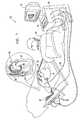
- FIGs. 1 and 2schematically illustrate a system 20 for catheterization of a heart 22 of a patient 24, in accordance with an embodiment of the present invention.
- the systemcomprises, inter alia, a catheter 28, which is inserted by a physician 26 into a chamber 30 of the heart through a vein or artery.
- Fig. 1is a pictorial view of the system as a whole, while Fig. 2 shows details of the distal end of the catheter.
- Catheter 28may serve as an active device for a variety of purposes, including diagnostic applications such as mapping or imaging of the heart, as well therapeutic applications, such as ablation-based treatment of arrhythmias.
- Catheter 28typically comprises a handle 32 for operation of the catheter by the physician. Suitable controls (not shown) on the handle enable the physician to steer, position and orient the distal end of the catheter as desired.
- catheter 24comprises, at its distal end, a number of functional components, including an electrode 40, which may be used for electrical sensing and/or ablation inside heart 22, as well as an acoustic transducer 42, which may be used for ultrasonic imaging.
- an electrode 40which may be used for electrical sensing and/or ablation inside heart 22
- an acoustic transducer 42which may be used for ultrasonic imaging.
- System 20comprises a positioning sub-system, which measures location and orientation coordinates of catheter 28.
- locationrefers to the spatial coordinates of the catheter
- orientationrefers to its angular coordinates.
- positionrefers to the full positional information of the catheter, which may comprise both location and orientation coordinates.
- the distal end of catheter 28contains a position sensor 36, which generates signals that are used by a positioning processor 38 in computing position coordinates of the catheter inside the heart.
- Sensor 36, as well as the functional components in catheter 28are connected to processor 38 by cables 44 running through the catheter.
- the positioning sub-systemcomprises a magnetic position tracking system that determines the location and orientation of catheter 28.
- the positioning sub-systemgenerates magnetic fields in a predefined working volume the vicinity of heart 22 and senses these fields at the catheter.
- the positioning sub-systemtypically comprises a set of external radiators, such as field generator coils 34, which are located in fixed, known positions external to patient 24 and generate electromagnetic fields in the vicinity of heart 22.
- the fields generated by coils 34thus define a fixed frame of reference.
- Position sensor 36 in this embodimentmay comprise one or more coils, which sense the fields generated by coils 34 and convey to processor 38 signals that are proportional to directional components of the fields.
- the processortypically receives, amplifies, filters, digitizes, and processes these signals in order to determine the coordinates of the sensor in the frame of reference of coils 34.
- a radiatorsuch as a coil, in the catheter generates electromagnetic fields, which are received by sensors outside the patient's body.
- position transducerin the context of the present patent application and in the claims, thus refers generically to any sort of component that can be used in an invasive device, such as a catheter, to generate signals indicative of the coordinates of the component, whether by transmission or reception of radiation.
- Magnetic position sensor 36is one type of position transducer and is described here solely by way of illustration, and not limitation.
- Position sensor 36is located within the distal end of catheter 28, adjacent to electrode 40 and transducer 42, as shown in Fig. 2 .
- the mutual locational and orientational offsets between the position sensor, electrode, and transducersare constant. These offsets are used by positioning processor 38 to derive the coordinates of electrode 40 and transducer 42, given the measured position of position sensor 36.
- system 20comprises two position reference elements:
- catheter 48is fed through the superior vena cava into the right atrium of heart 22, and its distal end is inserted into a coronary sinus 50.
- catheter 48is not expected to move relative to the heart during the procedure (and the coronary sinus itself moves relatively little in the course of the heart cycle).
- respiratory motion of the thorax of patient 24will cause the position of catheter 48, relative to reference pad 46, to shift cyclically along with catheter 28 and the rest of the patient's heart.
- Processor 38jointly processes the coordinates of sensor 36 with the coordinates of catheter 48 in order to find relative location coordinates of catheter 28 that neutralize the effects of respiration and other patient movement, as is described further hereinbelow.
- the coordinates of reference pad 46may also be used in this computation in order to enhance the stability of the coordinates against patient movement and changes in the operating environment.
- the processortypically uses the resulting accurate position measurements in generating maps and/or images of the heart, which are presented on a display 52, and in accurately tracking the location of catheter 28 during diagnostic and therapeutic procedures.
- a usersuch as physician 26, may interact with the display and may control processor using an input device 54, such as a pointing device and/or a keyboard.
- positioning processor 38comprises a general-purpose computer processor, which is programmed in software to carry out the functions described herein.
- the softwaremay be downloaded to the computer in electronic form, over a network, for example, or it may, alternatively or additionally, be stored on tangible media, such as optical, magnetic or electronic memory media.
- the functions of the positioning processormay be implemented using a dedicated computer, or they may be integrated with other computing functions of system 20. Additionally or alternatively, at least some of the processing functions may be performed using dedicated hardware.
- Fig. 3is a vector diagram that schematically illustrates location coordinates computed by processor 38, in accordance with an embodiment of the present invention.
- the diagramis two-dimensional (for the sake of simplicity and visual clarity), in practice the processor determines location coordinates in system 20 in three dimensions.
- the embodiments described hereinbelowrelate specifically to correction of location coordinates, the principles of the present invention may similarly be applied, mutatis mutandis, in reducing errors that may occur in the orientation coordinates of catheter 28, as well.
- Fig. 3shows the following vectors:
- Vectors 60 and 62are also expected to shift cyclically due to the beating motion of heart 22.
- the coordinate measurementsmay be synchronized with the heart cycle, by gating signal capture relative to a body-surface electrocardiogram (ECG) signal or a local intracardiac electrogram.
- the intracardiac electrogrammay be detected, for example, by an electrode on reference catheter 48.
- a certain point in the heart cyclesuch as the peak of the QRS wave in the ECG or a peak in the electrogram, is chosen as an annotation point, and the measurements of vectors 60 and 62 are made at the annotation point in each heart cycle or at a certain fixed delay relative to the annotation point.
- Fig. 4is a vector diagram that schematically illustrates a method applied by processor 38 in computing coordinates of catheter 28 relative to heart 22, in accordance with an embodiment of the present invention.
- vectors 60 and 62(A and B in Fig. 3 ) are referred to vector 64 (C) to give location vectors 66 (A-C) and 68 (B-C), corresponding to the location coordinates of catheters 28 and 48, respectively, in the frame of reference of pad 46.
- This frame of referenceis expected to be stationary, except to the extent that patient 24 moves during the procedure. When the patient does move, this movement is neutralized by referencing of the coordinates to pad 46.
- Processor 38subtracts vector 68 from vector 66 to give a relative location vector 70 of sensor 36 in the cardiac frame of reference defined by catheter 48.
- vector 64drops out of the final calculation, so that pad 46 is not critical in finding the relative location coordinates of catheter 28.
- the additional reference provided by pad 46is useful, however, in detecting and compensating for displacement of catheter 48 from its reference location, as will be explained further hereinbelow.
- Fig. 5is a flow chart that schematically illustrates a method for finding location coordinates of catheter 28 in system 20, in accordance with an embodiment of the present invention.
- the methodassumes, as its starting point, that reference catheter 48 has been inserted into heart 22 and placed in coronary sinus 50, as shown in Fig. 1 .
- Processor 38collects and processes coordinate readings provided by the position sensor in reference catheter 48 over a number of respiratory cycles of patient 24, at a location learning step 80.
- System 20may alert physician 26 that the learning phase is in progress, so that the physician can make sure not to do anything that might move the reference catheter accidentally during this phase.
- the coordinate readings collected during step 80are typically referred to the measured coordinates of reference pad 46, as explained above with reference to Fig. 4 .
- the "raw" coordinates of catheter 48 in the external frame of reference of field generator coils 34may be used.
- the readingsare typically taken at a certain reference point in the patient's heart cycle.
- Processor 38applies statistical processing to the coordinate readings in order to define the range of locations that is normally traversed by catheter 48 over the course of a respiration cycle.
- physician 26may begin to move catheter 28 within heart 22 in order to perform a diagnostic or therapeutic procedure.
- Processor 38receives signals from sensor 36 in catheter 28, as well as from the position sensors in catheter 48 and pad 46.
- the processorprocesses these signals to find the raw coordinates of catheters 28 and 48 and of pad 46 in the external frame of reference, and then jointly processes these raw coordinates to find the relative coordinates of catheter 28 in the cardiac frame of reference, as explained above with reference to Figs. 3 and 4 .
- the processorcompensates for the effect of patient respiration (as well as other possible movement of the patient) on the location coordinates of catheter 28, at a motion compensation step 82.
- the position of catheter 28 that is presented to physician 26(in a map on display 52, for example) reflects the actual position of the catheter in the frame of reference of the heart, irrespective of the overall movement of the heart due to respiratory motion or other causes.
- Processor 38continually monitors the coordinates of reference catheter 48 to ensure that they remain within the range that was learned at step 80. If the processor determines that the coordinates have deviated from the range by more than a permitted threshold, it alerts physician 26, at a reference movement detection step 84. For example, the processor may raise an alert when the reference catheter coordinates are more than 2 mm outside the range that was learned previously. In performing this measurement, it is desirable that processor 38 refer the coordinates of catheter 48 to pad 46, in order to distinguish actual displacement of the reference catheter in the heart from changes in the raw coordinates of the reference catheter that may occur due to movement of the patient during the procedure.
- physician 26has the choice of instructing processor 38 to correct and compensate for the displacement of reference catheter 48, or simply to continue with the procedure, at a user input step 86.
- system 20may decide autonomously to perform the correction.
- processor 38learns the new range of location coordinates of the reference catheter, at a correction step 90. This step is similar to step 80.
- the processorcompares the new range to the previous range in order to compute a correction vector, which estimates the displacement of the reference catheter.
- system 20returns to normal operation at step 82.
- the processornow subtracts out the correction vector in computing the relative coordinates of catheter 28, and thus compensates for the displacement of reference catheter 48.
- system 20will continue to display the relative position of catheter 28 in heart 22 as though the reference catheter had not moved from its original position. If the reference catheter moves again subsequently, the processor will repeat steps 84-90, and the new correction vector will then be added cumulatively to the previous correction vector.
- Fig. 6is a schematic, graphical representation of sets of position measurements 92, 96 of reference catheter 48, illustrating the operation of system 20 at steps 80 and 90 in accordance with an embodiment of the present invention.
- Processor 38gathers measurement points 92 at step 80.
- the measurement pointsare collected over the course of one or more respiratory cycles, typically at the same annotation point in the patient's heart cycle.
- respirationcauses mainly vertical motion of the reference catheter, as illustrated by points 92.
- the locations of points 92defines a range 94. In this case, the range is the smallest ellipse with a vertical major axis that contains all of points 92, but other methods may alternatively be used to define the range.
- the rangeis shown in Fig. 6 as comprising simply a "cloud" of coordinates, the range may, additionally or alternatively, be defined by kinematic features, such as the path and/or speed of movement from point to point.
- displacement of the reference cathetermay be detected at step 90 not only based on excursion of the coordinates outside the "cloud,” but also based on kinematic deviation.
- the processorAfter the processor has detected movement of the reference catheter outside the expected range at step 84, it gathers a new set of measurement points 96 at step 90. Typically, this procedure can be completed over one or a few respiratory cycles. Points 96 define a new range 98.
- the processorcomputes a correction vector 100 by comparing ranges 94 and 98. For example, as shown in Fig. 6 , the correction vector may be given by the vector displacement between the centers of mass of old range 94 and new range 98.
- reference catheter 48includes one or more electrodes
- displacement of the reference cathetermay also be detected electrically.
- the timing of a peak in the local electrogram detected by the reference catheter electrodemay be compared with the QRS peak in the body-surface ECG. A shift in this timing may indicate that the reference catheter has moved.
- the reference catheterhas multiple electrodes at different positions along its length, a relative shift in the locations of the peaks in the electrograms detected by the different electrodes may likewise indicate that the reference catheter has moved.
Landscapes
- Health & Medical Sciences (AREA)
- Life Sciences & Earth Sciences (AREA)
- Engineering & Computer Science (AREA)
- General Health & Medical Sciences (AREA)
- Surgery (AREA)
- Veterinary Medicine (AREA)
- Public Health (AREA)
- Animal Behavior & Ethology (AREA)
- Biomedical Technology (AREA)
- Medical Informatics (AREA)
- Molecular Biology (AREA)
- Heart & Thoracic Surgery (AREA)
- Biophysics (AREA)
- Physics & Mathematics (AREA)
- Pathology (AREA)
- Nuclear Medicine, Radiotherapy & Molecular Imaging (AREA)
- Radiology & Medical Imaging (AREA)
- Human Computer Interaction (AREA)
- Optics & Photonics (AREA)
- Measurement And Recording Of Electrical Phenomena And Electrical Characteristics Of The Living Body (AREA)
- Endoscopes (AREA)
- Media Introduction/Drainage Providing Device (AREA)
- Ultra Sonic Daignosis Equipment (AREA)
- Measuring And Recording Apparatus For Diagnosis (AREA)
- Electrotherapy Devices (AREA)
- Measurement Of Length, Angles, Or The Like Using Electric Or Magnetic Means (AREA)
- Prostheses (AREA)
- Eye Examination Apparatus (AREA)
Abstract
Description
- This application claims the benefit of
U.S. Provisional Patent Application 60/941,767, filed June 4, 2007 - The present invention relates generally to medical instruments, and specifically to position sensing systems for tracking the location of invasive devices inside the body.
- In intracardiac tracking systems, such as CARTO™ (produced by Biosense Webster, Diamond Bar, California), the position coordinates of a catheter inside the heart are determined relative to a reference location outside the patient's body. In CARTO, for example, both the catheter and a reference pad under the patient's back contain miniature coils, which sense the amplitude and direction of a magnetic field. As the patient breathes, however, the resulting movement of the patient's thorax causes the heart to shift position relative to the reference pad, so that the coordinates of the catheter will change during the respiratory cycle even while the catheter is stationary relative to the heart.
U.S. Patent 5,391,199 , whose disclosure is incorporated herein by reference, describes an apparatus and method for mapping and treatment of cardiac arrhythmias using a catheter with location sensing capability inside the heart. To correct for displacement of the heart chamber that may occur because of breathing or patient movement, a set of more than two locatable catheters may be placed at specific points in the heart chamber during the mapping procedures to serve as reference catheters. The location of these reference catheters supplies the necessary information for proper three-dimensional correspondence of the mapping catheter location within the heart chamber.- The use of a reference probe, such as a catheter, in a stable position inside the heart can enhance accuracy in measuring the position of an active device, such as a mapping catheter, as the active device is maneuvered within the heart. The reference probe is held stationary and serves as a reference point for measuring the relative coordinates of the active device. Since respiratory motion affects both the reference catheter and the active device in roughly the same way, the effect of respiratory motion on the coordinates of the active device can thus be largely eliminated.
- In practice, however, it can be difficult to maintain the stability of the reference probe. Even small displacements of the reference probe can seriously compromise the accuracy of measurement of the position of the active device. Embodiments of the present invention that are described hereinbelow provide methods and systems that can be used to address this problem, and thus provide accurate position readings even when the reference probe is not entirely stable.
- There is therefore provided, in accordance with an embodiment of the present invention, a method for position tracking, including:
- placing an internal reference probe, which includes a first position transducer, in a reference location within a heart of a subject;
- collecting and processing first location coordinates of the internal reference probe in a fixed frame of reference, using the first position transducer, during one or more respiratory cycles of the subject so as to define a range of the location coordinates corresponding to the reference location;
- inserting an active device, which includes a second position transducer, into the heart;
- collecting second location coordinates of the active device in the fixed frame of reference, using the second position transducer, and jointly processing the first and second location coordinates so as to find relative location coordinates of the active device in a cardiac frame of reference;
- after defining the range of the location coordinates corresponding to the reference location, detecting a deviation of the first location coordinates from the range, thereby identifying a displacement of the reference probe from the reference location; and
- correcting the relative location coordinates so as to compensate for the displacement.
- In a disclosed embodiment, the internal reference probe and the active device include catheters, and the first and second position transducers include magnetic field sensors, which are configured to output position signals responsively to magnetic fields generated by field generators in the fixed frame of reference.
- In one embodiment, jointly processing the first and second location coordinates includes taking a vector difference between the first and second location coordinates in order to find the relative location coordinates.
- The method made include collecting third location coordinates, in the fixed frame of reference, of a reference pad that is fixed to a body of the subject, wherein jointly processing the first and second location coordinates includes referring at least the first location coordinates to the third location coordinates. Typically, detecting the deviation includes comparing the first location coordinates to the third location coordinates so as to determine whether the deviation is due to the displacement of the reference probe from the reference location or due to a movement of the body of the subject.
- In a disclosed embodiment, correcting the relative location coordinates includes computing a correction vector responsively to the displacement, and applying the correction vector in finding the relative location coordinates based on the first and second location coordinates. Typically, computing the correction vector includes collecting and processing further location coordinates of the internal reference probe so as to define a new range of the location coordinates corresponding to the reference location, and comparing the new range to the range that was defined by collecting and processing the first location coordinates.
- In one embodiment, the method includes sensing a local electrogram signal at the reference location within the heart using an electrode on the internal reference probe, wherein detecting the deviation includes detecting a change in the local electrogram signal.
- There is also provided, in accordance with an embodiment of the present invention, apparatus for position tracking, including:
- an internal reference probe, which includes a first position transducer and is configured to be placed in a reference location within a heart of a subject;
- an active device, which includes a second position transducer and is configured to be introduced into the heart; and
- a positioning processor, which is coupled to collect and process first location coordinates of the internal reference probe in a fixed frame of reference, using the first position transducer, during one or more respiratory cycles of the subject so as to define a range of the location coordinates corresponding to the reference location, and to collect second location coordinates of the active device in the fixed frame of reference, using the second position transducer, and to jointly process the first and second location coordinates so as to find relative location coordinates of the active device in a cardiac frame of reference,
- The present invention will be more fully understood from the following detailed description of the embodiments thereof, taken together with the drawings in which:
Fig. 1 is a schematic, pictorial illustration of a cardiac catheterization system, in accordance with an embodiment of the present invention;Fig. 2 is a schematic side view of the distal end of a catheter, in accordance with an embodiment of the present invention;Figs. 3 and 4 are vector diagrams that schematically illustrate a method for finding location coordinates of a catheter, in accordance with an embodiment of the present invention;Fig. 5 is a flow chart that schematically illustrates a method for finding location coordinates of a catheter, in accordance with an embodiment of the present invention; andFig. 6 is a graphical representation of sets of position measurements of a reference catheter, in accordance with an embodiment of the present invention.- Reference is now made to
Figs. 1 and2 , which schematically illustrate asystem 20 for catheterization of aheart 22 of apatient 24, in accordance with an embodiment of the present invention. The system comprises, inter alia, acatheter 28, which is inserted by aphysician 26 into achamber 30 of the heart through a vein or artery.Fig. 1 is a pictorial view of the system as a whole, whileFig. 2 shows details of the distal end of the catheter. Catheter 28 may serve as an active device for a variety of purposes, including diagnostic applications such as mapping or imaging of the heart, as well therapeutic applications, such as ablation-based treatment of arrhythmias.Catheter 28 typically comprises ahandle 32 for operation of the catheter by the physician. Suitable controls (not shown) on the handle enable the physician to steer, position and orient the distal end of the catheter as desired. In the example configuration shown inFig. 2 ,catheter 24 comprises, at its distal end, a number of functional components, including anelectrode 40, which may be used for electrical sensing and/or ablation insideheart 22, as well as anacoustic transducer 42, which may be used for ultrasonic imaging. These components, however, are shown solely by way of illustration, and the principles of the present invention are equally applicable to other types of catheters, as well as other invasive devices.System 20 comprises a positioning sub-system, which measures location and orientation coordinates ofcatheter 28. (Throughout this patent application and in the claims, the term "location" refers to the spatial coordinates of the catheter, and the term "orientation" refers to its angular coordinates. The term "position" refers to the full positional information of the catheter, which may comprise both location and orientation coordinates.) For the purpose of these coordinate measurements, the distal end ofcatheter 28 contains aposition sensor 36, which generates signals that are used by apositioning processor 38 in computing position coordinates of the catheter inside the heart.Sensor 36, as well as the functional components incatheter 28, are connected toprocessor 38 bycables 44 running through the catheter.- In one embodiment, the positioning sub-system comprises a magnetic position tracking system that determines the location and orientation of
catheter 28. The positioning sub-system generates magnetic fields in a predefined working volume the vicinity ofheart 22 and senses these fields at the catheter. For this purpose, the positioning sub-system typically comprises a set of external radiators, such asfield generator coils 34, which are located in fixed, known positions external topatient 24 and generate electromagnetic fields in the vicinity ofheart 22. The fields generated bycoils 34 thus define a fixed frame of reference.Position sensor 36 in this embodiment may comprise one or more coils, which sense the fields generated bycoils 34 and convey toprocessor 38 signals that are proportional to directional components of the fields. The processor typically receives, amplifies, filters, digitizes, and processes these signals in order to determine the coordinates of the sensor in the frame of reference ofcoils 34. In an alternative embodiment, a radiator, such as a coil, in the catheter generates electromagnetic fields, which are received by sensors outside the patient's body. - The principles of operation of this sort of positioning sub-system are further described in the above-mentioned
U.S. Patent 5,391,199 . Other position tracking systems that operate in this general manner are described, for example, inU.S. Patents 6,690,963 ,6,618,612 and6,332,089 , andU.S. Patent Application Publications 2002/0065455 A1 ,2004/0147920 A1 and2004/0068178 A1 , whose disclosures are all incorporated herein by reference. Integration of the positioning sub-system with the ultrasonic imaging capabilities oftransducer 42 is described inU.S. Patent Application Publication 2006/0241445 , whose disclosure is also incorporated herein by reference. Although the positioning sub-system ofFig. 1 uses magnetic fields, the methods described below may likewise be implemented using any other suitable positioning sub-system, such as systems based on electrical impedance or acoustical measurements. The term "position transducer," in the context of the present patent application and in the claims, thus refers generically to any sort of component that can be used in an invasive device, such as a catheter, to generate signals indicative of the coordinates of the component, whether by transmission or reception of radiation.Magnetic position sensor 36 is one type of position transducer and is described here solely by way of illustration, and not limitation. Position sensor 36 is located within the distal end ofcatheter 28, adjacent toelectrode 40 andtransducer 42, as shown inFig. 2 . Typically, the mutual locational and orientational offsets between the position sensor, electrode, and transducers are constant. These offsets are used by positioningprocessor 38 to derive the coordinates ofelectrode 40 andtransducer 42, given the measured position ofposition sensor 36.- In order to reduce possible errors in the position coordinates of
catheter 28 that are computed byprocessor 38,system 20 comprises two position reference elements: - A
reference pad 46, which is typically attached to the back ofpatient 24.Pad 46 comprises one or more position transducers, such as a position sensor similar tosensor 36 incatheter 28. (In fact, the pad may itself simply comprise another catheter likecatheter 28.) The signal that is output by the sensor inpad 46 thus provides a stable position reference, which does not move during the procedure carried out byphysician 26 unless the patient himself moves. The reference pad may, for example, be a QWIKSTAR back pad, which is supplied as part of the above-mentioned CARTO system. - A
reference catheter 48, which is typically inserted byphysician 26 intoheart 22 and is positioned within the heart at a known, stable reference location.Catheter 48 likewise comprises one or more position transducers and thus serves as the reference probe for finding relative location coordinates ofcatheter 28 in a cardiac frame of reference, i.e., a reference frame that is anchored inheart 22, rather than external to the patient's body, as described further hereinbelow. The reference catheter may, for example, be a CARTO NAVISTAR catheter. - In the inset in
Fig. 1 , for example,catheter 48 is fed through the superior vena cava into the right atrium ofheart 22, and its distal end is inserted into acoronary sinus 50. In general, in this sort of position,catheter 48 is not expected to move relative to the heart during the procedure (and the coronary sinus itself moves relatively little in the course of the heart cycle). On the other hand, respiratory motion of the thorax ofpatient 24 will cause the position ofcatheter 48, relative toreference pad 46, to shift cyclically along withcatheter 28 and the rest of the patient's heart. Processor 38 jointly processes the coordinates ofsensor 36 with the coordinates ofcatheter 48 in order to find relative location coordinates ofcatheter 28 that neutralize the effects of respiration and other patient movement, as is described further hereinbelow. The coordinates ofreference pad 46 may also be used in this computation in order to enhance the stability of the coordinates against patient movement and changes in the operating environment. The processor typically uses the resulting accurate position measurements in generating maps and/or images of the heart, which are presented on adisplay 52, and in accurately tracking the location ofcatheter 28 during diagnostic and therapeutic procedures. A user, such asphysician 26, may interact with the display and may control processor using aninput device 54, such as a pointing device and/or a keyboard.- Typically, positioning
processor 38 comprises a general-purpose computer processor, which is programmed in software to carry out the functions described herein. The software may be downloaded to the computer in electronic form, over a network, for example, or it may, alternatively or additionally, be stored on tangible media, such as optical, magnetic or electronic memory media. The functions of the positioning processor may be implemented using a dedicated computer, or they may be integrated with other computing functions ofsystem 20. Additionally or alternatively, at least some of the processing functions may be performed using dedicated hardware. Fig. 3 is a vector diagram that schematically illustrates location coordinates computed byprocessor 38, in accordance with an embodiment of the present invention. Although the diagram is two-dimensional (for the sake of simplicity and visual clarity), in practice the processor determines location coordinates insystem 20 in three dimensions. Furthermore, although the embodiments described hereinbelow relate specifically to correction of location coordinates, the principles of the present invention may similarly be applied, mutatis mutandis, in reducing errors that may occur in the orientation coordinates ofcatheter 28, as well.Fig. 3 shows the following vectors:- A vector 60 (marked A) represents the coordinates of
sensor 36 incatheter 28, which are computed byprocessor 38 relative to the fixed, external frame of reference of field generator coils 34. These are absolute coordinates, which do not take into account any movement ofpatient 24, which may occur due to respiration or any other cause. - Another vector 62 (marked B) represents the coordinates of
reference catheter 48, which is supposed to remain stationary (relative to heart 22) withincoronary sinus 50. These are, again, absolute coordinates. They are expected to shift cyclically due to respiration ofpatient 24 and may also exhibit a fixed shift if either patient 24 moves during the procedure orcatheter 48 moves withinheart 22. Methods for dealing with these sorts of shifts are described hereinbelow. - A vector 64 (marked C) represents the coordinates of
reference pad 46, which are not expected to change at all. Vectors heart 22. In order to neutralize this motion component, the coordinate measurements may be synchronized with the heart cycle, by gating signal capture relative to a body-surface electrocardiogram (ECG) signal or a local intracardiac electrogram. The intracardiac electrogram may be detected, for example, by an electrode onreference catheter 48. A certain point in the heart cycle, such as the peak of the QRS wave in the ECG or a peak in the electrogram, is chosen as an annotation point, and the measurements ofvectors vectors Fig. 4 is a vector diagram that schematically illustrates a method applied byprocessor 38 in computing coordinates ofcatheter 28 relative toheart 22, in accordance with an embodiment of the present invention. As shown in this figure,vectors 60 and 62 (A and B inFig. 3 ) are referred to vector 64 (C) to give location vectors 66 (A-C) and 68 (B-C), corresponding to the location coordinates ofcatheters pad 46. This frame of reference is expected to be stationary, except to the extent thatpatient 24 moves during the procedure. When the patient does move, this movement is neutralized by referencing of the coordinates to pad 46.Processor 38 subtractsvector 68 fromvector 66 to give arelative location vector 70 ofsensor 36 in the cardiac frame of reference defined bycatheter 48. The resultingvector 70 is given by (A-C) - (B-C) = (A-B). As illustrated by this formula,vector 64 drops out of the final calculation, so thatpad 46 is not critical in finding the relative location coordinates ofcatheter 28. The additional reference provided bypad 46 is useful, however, in detecting and compensating for displacement ofcatheter 48 from its reference location, as will be explained further hereinbelow.Fig. 5 is a flow chart that schematically illustrates a method for finding location coordinates ofcatheter 28 insystem 20, in accordance with an embodiment of the present invention. The method assumes, as its starting point, thatreference catheter 48 has been inserted intoheart 22 and placed incoronary sinus 50, as shown inFig. 1 .Processor 38 collects and processes coordinate readings provided by the position sensor inreference catheter 48 over a number of respiratory cycles ofpatient 24, at alocation learning step 80.System 20 may alertphysician 26 that the learning phase is in progress, so that the physician can make sure not to do anything that might move the reference catheter accidentally during this phase.- The coordinate readings collected during
step 80 are typically referred to the measured coordinates ofreference pad 46, as explained above with reference toFig. 4 . Alternatively, if patient movement (other than respiratory motion) can be neglected, the "raw" coordinates ofcatheter 48 in the external frame of reference of field generator coils 34 may be used. As noted above, the readings are typically taken at a certain reference point in the patient's heart cycle.Processor 38 applies statistical processing to the coordinate readings in order to define the range of locations that is normally traversed bycatheter 48 over the course of a respiration cycle. - Once the learning phase is complete,
physician 26 may begin to movecatheter 28 withinheart 22 in order to perform a diagnostic or therapeutic procedure.Processor 38 receives signals fromsensor 36 incatheter 28, as well as from the position sensors incatheter 48 andpad 46. The processor processes these signals to find the raw coordinates ofcatheters pad 46 in the external frame of reference, and then jointly processes these raw coordinates to find the relative coordinates ofcatheter 28 in the cardiac frame of reference, as explained above with reference toFigs. 3 and 4 . In this way, the processor compensates for the effect of patient respiration (as well as other possible movement of the patient) on the location coordinates ofcatheter 28, at amotion compensation step 82. In other words, the position ofcatheter 28 that is presented to physician 26 (in a map ondisplay 52, for example) reflects the actual position of the catheter in the frame of reference of the heart, irrespective of the overall movement of the heart due to respiratory motion or other causes. Processor 38 continually monitors the coordinates ofreference catheter 48 to ensure that they remain within the range that was learned atstep 80. If the processor determines that the coordinates have deviated from the range by more than a permitted threshold, it alertsphysician 26, at a referencemovement detection step 84. For example, the processor may raise an alert when the reference catheter coordinates are more than 2 mm outside the range that was learned previously. In performing this measurement, it is desirable thatprocessor 38 refer the coordinates ofcatheter 48 to pad 46, in order to distinguish actual displacement of the reference catheter in the heart from changes in the raw coordinates of the reference catheter that may occur due to movement of the patient during the procedure.- Typically, after receiving the alert,
physician 26 has the choice of instructingprocessor 38 to correct and compensate for the displacement ofreference catheter 48, or simply to continue with the procedure, at auser input step 86. Alternatively,system 20 may decide autonomously to perform the correction. In either case, when the decision has been made to correct the coordinates,processor 38 learns the new range of location coordinates of the reference catheter, at acorrection step 90. This step is similar to step 80. The processor compares the new range to the previous range in order to compute a correction vector, which estimates the displacement of the reference catheter. - Once the processor has found the correction vector,
system 20 returns to normal operation atstep 82. The processor now subtracts out the correction vector in computing the relative coordinates ofcatheter 28, and thus compensates for the displacement ofreference catheter 48. As a result,system 20 will continue to display the relative position ofcatheter 28 inheart 22 as though the reference catheter had not moved from its original position. If the reference catheter moves again subsequently, the processor will repeat steps 84-90, and the new correction vector will then be added cumulatively to the previous correction vector. Fig. 6 is a schematic, graphical representation of sets ofposition measurements reference catheter 48, illustrating the operation ofsystem 20 atsteps Processor 38 gathers measurement points 92 atstep 80. As noted earlier, the measurement points are collected over the course of one or more respiratory cycles, typically at the same annotation point in the patient's heart cycle. Assuming the patient to be supine, respiration causes mainly vertical motion of the reference catheter, as illustrated bypoints 92. The locations ofpoints 92 defines arange 94. In this case, the range is the smallest ellipse with a vertical major axis that contains all ofpoints 92, but other methods may alternatively be used to define the range.- Although the range is shown in
Fig. 6 as comprising simply a "cloud" of coordinates, the range may, additionally or alternatively, be defined by kinematic features, such as the path and/or speed of movement from point to point. In this case, displacement of the reference catheter may be detected atstep 90 not only based on excursion of the coordinates outside the "cloud," but also based on kinematic deviation. - In any case, after the processor has detected movement of the reference catheter outside the expected range at
step 84, it gathers a new set of measurement points 96 atstep 90. Typically, this procedure can be completed over one or a few respiratory cycles.Points 96 define anew range 98. The processor computes acorrection vector 100 by comparingranges Fig. 6 , the correction vector may be given by the vector displacement between the centers of mass ofold range 94 andnew range 98. - If
reference catheter 48 includes one or more electrodes, displacement of the reference catheter may also be detected electrically. For example, the timing of a peak in the local electrogram detected by the reference catheter electrode may be compared with the QRS peak in the body-surface ECG. A shift in this timing may indicate that the reference catheter has moved. As another example, if the reference catheter has multiple electrodes at different positions along its length, a relative shift in the locations of the peaks in the electrograms detected by the different electrodes may likewise indicate that the reference catheter has moved. These timing changes are independent of the actual position measurements and are generally not sensitive to patient motion. - It will be appreciated that the embodiments described above are cited by way of example, and that the present invention is not limited to what has been particularly shown and described hereinabove. Rather, the scope of the present invention includes both combinations and subcombinations of the various features described hereinabove, as well as variations and modifications thereof which would occur to persons skilled in the art upon reading the foregoing description and which are not disclosed in the prior art.
Claims (18)
- A method for position tracking, comprising:placing an internal reference probe, which comprises a first position transducer, in a reference location within a heart of a subject;collecting and processing first location coordinates of the internal reference probe in a fixed frame of reference, using the first position transducer, during one or more respiratory cycles of the subject so as to define a range of the location coordinates corresponding to the reference location;inserting an active device, which comprises a second position transducer, into the heart;collecting second location coordinates of the active device in the fixed frame of reference, using the second position transducer, and jointly processing the first and second location coordinates so as to find relative location coordinates of the active device in a cardiac frame of reference;after defining the range of the location coordinates corresponding to the reference location, detecting a deviation of the first location coordinates from the range, thereby identifying a displacement of the reference probe from the reference location; andcorrecting the relative location coordinates so as to compensate for the displacement.
- The method according to claim 1, wherein the internal reference probe and the active device comprise catheters.
- The method according to claim 1, wherein the first and second position transducers comprise magnetic field sensors, which are configured to output position signals responsively to magnetic fields generated by field generators in the fixed frame of reference.
- The method according to claim 1, wherein jointly processing the first and second location coordinates comprises taking a vector difference between the first and second location coordinates in order to find the relative location coordinates.
- The method according to claim 1, and comprising collecting third location coordinates, in the fixed frame of reference, of a reference pad that is fixed to a body of the subject, wherein jointly processing the first and second location coordinates comprises referring at least the first location coordinates to the third location coordinates.
- The method according to claim 5, wherein detecting the deviation comprises comparing the first location coordinates to the third location coordinates so as to determine whether the deviation is due to the displacement of the reference probe from the reference location or due to a movement of the body of the subject.
- The method according to claim 1, wherein correcting the relative location coordinates comprises computing a correction vector responsively to the displacement, and applying the correction vector in finding the relative location coordinates based on the first and second location coordinates.
- The method according to claim 7, wherein computing the correction vector comprises collecting and processing further location coordinates of the internal reference probe so as to define a new range of the location coordinates corresponding to the reference location, and comparing the new range to the range that was defined by collecting and processing the first location coordinates.
- The method according to claim 1, and comprising sensing a local electrogram signal at the reference location within the heart using an electrode on the internal reference probe, wherein detecting the deviation comprises detecting a change in the local electrogram signal.
- Apparatus for position tracking, comprising:an internal reference probe, which comprises a first position transducer and is configured to be placed in a reference location within a heart of a subject;an active device, which comprises a second position transducer and is configured to be introduced into the heart; anda positioning processor, which is coupled to collect and process first location coordinates of the internal reference probe in a fixed frame of reference, using the first position transducer, during one or more respiratory cycles of the subject so as to define a range of the location coordinates corresponding to the reference location, and to collect second location coordinates of the active device in the fixed frame of reference, using the second position transducer, and to jointly process the first and second location coordinates so as to find relative location coordinates of the active device in a cardiac frame of reference,wherein the positioning processor is configured, after defining the range of the location coordinates corresponding to the reference location, to detect a deviation of the first location coordinates from the range, thereby identifying a displacement of the reference probe from the reference location, and to correct the relative location coordinates so as to compensate for the displacement.
- The apparatus according to claim 10, wherein the internal reference probe and the active device comprise catheters.
- The apparatus according to claim 10, and comprising magnetic field generators, which are configured to generate magnetic fields that define the fixed frame of reference, wherein the first and second position transducers comprise magnetic field sensors, which are configured to output position signals responsively to magnetic fields.
- The apparatus according to claim 10, wherein the positioning processor is configured to take a vector difference between the first and second location coordinates in order to find the relative location coordinates.
- The apparatus according to claim 10, and comprising a reference pad that is fixed to a body of the subject, wherein the positioning processor is coupled to collect third location coordinates, in the fixed frame of reference, of the reference pad and to refer at least the first location coordinates to the third location coordinates in order to find the relative location coordinates.
- The apparatus according to claim 6, wherein the positioning processor is configured to compare the first location coordinates to the third location coordinates so as to determine whether the deviation is due to the displacement of the reference probe from the reference location or due to a movement of the body of the subject.
- The apparatus according to claim 10, wherein the positioning processor is configured to compute a correction vector responsively to the displacement, and to apply the correction vector in finding the relative location coordinates based on the first and second location coordinates.
- The apparatus according to claim 16, wherein the positioning processor is configured to collect and process further location coordinates of the internal reference probe, after detecting the deviation, so as to define a new range of the location coordinates corresponding to the reference location, and to compute the correction vector by comparing the new range to the range that was defined by collecting and processing the first location coordinates.
- The apparatus according to claim 10, wherein the internal reference probe comprises an electrode, and wherein the positioning processor is coupled to receive a local electrogram signal from the electrode at the reference location within the heart and to detect the deviation by detecting a change in the local electrogram signal.
Applications Claiming Priority (2)
| Application Number | Priority Date | Filing Date | Title |
|---|---|---|---|
| US94176707P | 2007-06-04 | 2007-06-04 | |
| US12/129,012US20090030307A1 (en) | 2007-06-04 | 2008-05-29 | Intracorporeal location system with movement compensation |
Publications (2)
| Publication Number | Publication Date |
|---|---|
| EP2000088A1true EP2000088A1 (en) | 2008-12-10 |
| EP2000088B1 EP2000088B1 (en) | 2010-09-22 |
Family
ID=39765034
Family Applications (1)
| Application Number | Title | Priority Date | Filing Date |
|---|---|---|---|
| EP20080251922ActiveEP2000088B1 (en) | 2007-06-04 | 2008-06-03 | Intracorporeal location system with movement compensation |
Country Status (12)
| Country | Link |
|---|---|
| US (1) | US20090030307A1 (en) |
| EP (1) | EP2000088B1 (en) |
| JP (1) | JP5323397B2 (en) |
| KR (1) | KR20080106861A (en) |
| CN (1) | CN101327124B (en) |
| AT (1) | ATE481924T1 (en) |
| AU (1) | AU2008202443B2 (en) |
| BR (1) | BRPI0803078A2 (en) |
| CA (1) | CA2633209C (en) |
| DE (1) | DE602008002638D1 (en) |
| IL (1) | IL191925A (en) |
| MX (1) | MX2008007160A (en) |
Cited By (1)
| Publication number | Priority date | Publication date | Assignee | Title |
|---|---|---|---|---|
| EP3662825A1 (en)* | 2018-12-04 | 2020-06-10 | Biosense Webster (Israel) Ltd. | Coronary sinus (cs) catheter movement detection |
Families Citing this family (61)
| Publication number | Priority date | Publication date | Assignee | Title |
|---|---|---|---|---|
| US9585586B2 (en) | 2006-12-29 | 2017-03-07 | St. Jude Medical, Atrial Fibrillation Division, Inc. | Navigational reference dislodgement detection method and system |
| US8532734B2 (en)* | 2008-04-18 | 2013-09-10 | Regents Of The University Of Minnesota | Method and apparatus for mapping a structure |
| US8290571B2 (en)* | 2008-08-01 | 2012-10-16 | Koninklijke Philips Electronics N.V. | Auxiliary cavity localization |
| CN101836862B (en)* | 2009-03-16 | 2014-03-26 | 上海微创医疗器械(集团)有限公司 | Three-dimensional mapping method of human chamber inner wall and equipment and system thereof |
| US9675302B2 (en)* | 2009-12-31 | 2017-06-13 | Mediguide Ltd. | Prolapse detection and tool dislodgement detection |
| US9820695B2 (en)* | 2010-03-29 | 2017-11-21 | St. Jude Medical International Holding S.àr.l. | Method for detecting contact with the wall of a region of interest |
| US8672837B2 (en) | 2010-06-24 | 2014-03-18 | Hansen Medical, Inc. | Methods and devices for controlling a shapeable medical device |
| US9254146B2 (en) | 2010-10-18 | 2016-02-09 | Avent, Inc. | Echogenic nerve block apparatus and system |
| JP5795080B2 (en)* | 2010-12-17 | 2015-10-14 | セント・ジュード・メディカル・エイトリアル・フィブリレーション・ディヴィジョン・インコーポレーテッド | Navigation standard deviation detection method and system |
| US9414770B2 (en) | 2010-12-29 | 2016-08-16 | Biosense Webster (Israel) Ltd. | Respiratory effect reduction in catheter position sensing |
| US9113824B2 (en)* | 2011-01-31 | 2015-08-25 | Biosense Webster (Israel), Ltd. | Compensation for respiratory motion |
| US9387048B2 (en) | 2011-10-14 | 2016-07-12 | Intuitive Surgical Operations, Inc. | Catheter sensor systems |
| US10238837B2 (en)* | 2011-10-14 | 2019-03-26 | Intuitive Surgical Operations, Inc. | Catheters with control modes for interchangeable probes |
| US20130303944A1 (en) | 2012-05-14 | 2013-11-14 | Intuitive Surgical Operations, Inc. | Off-axis electromagnetic sensor |
| US9452276B2 (en) | 2011-10-14 | 2016-09-27 | Intuitive Surgical Operations, Inc. | Catheter with removable vision probe |
| CA2856519C (en)* | 2011-11-22 | 2020-11-03 | Ascension Technology Corporation | Tracking a guidewire |
| US10588543B2 (en)* | 2012-05-23 | 2020-03-17 | Biosense Webster (Israel), Ltd. | Position sensing using electric dipole fields |
| US9057600B2 (en) | 2013-03-13 | 2015-06-16 | Hansen Medical, Inc. | Reducing incremental measurement sensor error |
| US9629595B2 (en) | 2013-03-15 | 2017-04-25 | Hansen Medical, Inc. | Systems and methods for localizing, tracking and/or controlling medical instruments |
| US9014851B2 (en) | 2013-03-15 | 2015-04-21 | Hansen Medical, Inc. | Systems and methods for tracking robotically controlled medical instruments |
| US9271663B2 (en) | 2013-03-15 | 2016-03-01 | Hansen Medical, Inc. | Flexible instrument localization from both remote and elongation sensors |
| US11020016B2 (en) | 2013-05-30 | 2021-06-01 | Auris Health, Inc. | System and method for displaying anatomy and devices on a movable display |
| WO2015187371A1 (en)* | 2014-06-03 | 2015-12-10 | Boston Scientific Scimed, Inc. | Medical devices for mapping cardiac tissue |
| US10506939B2 (en)* | 2015-08-11 | 2019-12-17 | Biosense Webster (Israel) Ltd. | Matching and tracking time sequences of heart activation |
| JP6824967B2 (en) | 2015-09-18 | 2021-02-03 | オーリス ヘルス インコーポレイテッド | Tubular net navigation |
| US10143526B2 (en) | 2015-11-30 | 2018-12-04 | Auris Health, Inc. | Robot-assisted driving systems and methods |
| KR102448919B1 (en)* | 2016-03-16 | 2022-10-04 | 삼성디스플레이 주식회사 | Display device |
| US11413429B2 (en)* | 2016-06-01 | 2022-08-16 | Becton, Dickinson And Company | Medical devices, systems and methods utilizing permanent magnet and magnetizable feature |
| CN110072449B (en)* | 2016-11-16 | 2023-02-24 | 纳维斯国际有限公司 | Esophageal position detection by electrical mapping |
| US10244926B2 (en) | 2016-12-28 | 2019-04-02 | Auris Health, Inc. | Detecting endolumenal buckling of flexible instruments |
| WO2018183727A1 (en) | 2017-03-31 | 2018-10-04 | Auris Health, Inc. | Robotic systems for navigation of luminal networks that compensate for physiological noise |
| US10022192B1 (en) | 2017-06-23 | 2018-07-17 | Auris Health, Inc. | Automatically-initialized robotic systems for navigation of luminal networks |
| CN116725667A (en) | 2017-06-28 | 2023-09-12 | 奥瑞斯健康公司 | System for providing positioning information and method for positioning an instrument within an anatomical structure |
| US11058493B2 (en) | 2017-10-13 | 2021-07-13 | Auris Health, Inc. | Robotic system configured for navigation path tracing |
| US10555778B2 (en) | 2017-10-13 | 2020-02-11 | Auris Health, Inc. | Image-based branch detection and mapping for navigation |
| US11510736B2 (en) | 2017-12-14 | 2022-11-29 | Auris Health, Inc. | System and method for estimating instrument location |
| WO2019125964A1 (en) | 2017-12-18 | 2019-06-27 | Auris Health, Inc. | Methods and systems for instrument tracking and navigation within luminal networks |
| CN109991923B (en)* | 2017-12-29 | 2021-10-01 | 富泰华工业(深圳)有限公司 | Multi-angle machining coordinate calculation and compensation device, method and storage equipment |
| WO2019191144A1 (en) | 2018-03-28 | 2019-10-03 | Auris Health, Inc. | Systems and methods for registration of location sensors |
| JP7225259B2 (en) | 2018-03-28 | 2023-02-20 | オーリス ヘルス インコーポレイテッド | Systems and methods for indicating probable location of instruments |
| US11806083B2 (en)* | 2018-05-14 | 2023-11-07 | Biosense Webster (Israel) Ltd. | Correcting map shifting of a position tracking system including repositioning the imaging system and the patient in response to detecting magnetic interference |
| US11877840B2 (en)* | 2018-05-29 | 2024-01-23 | Biosense Webster (Israel) Ltd. | Catheter localization using current location combined with magnetic-field sensing |
| US10905499B2 (en) | 2018-05-30 | 2021-02-02 | Auris Health, Inc. | Systems and methods for location sensor-based branch prediction |
| JP7371026B2 (en) | 2018-05-31 | 2023-10-30 | オーリス ヘルス インコーポレイテッド | Path-based navigation of tubular networks |
| KR102567087B1 (en) | 2018-05-31 | 2023-08-17 | 아우리스 헬스, 인코포레이티드 | Robotic systems and methods for navigation of luminal networks detecting physiological noise |
| MX2020012904A (en) | 2018-05-31 | 2021-02-26 | Auris Health Inc | Image-based airway analysis and mapping. |
| CN112804959B (en) | 2018-09-28 | 2025-01-28 | 奥瑞斯健康公司 | Robotic systems and methods for accompanying endoscopic and percutaneous medical procedures |
| US11123142B2 (en) | 2018-12-06 | 2021-09-21 | Biosense Webster (Israel) Ltd. | Quick registration of coordinate systems for robotic surgery |
| US12144604B2 (en) | 2018-12-11 | 2024-11-19 | Respinor As | Systems and methods for motion compensation in ultrasonic respiration monitoring |
| WO2020121199A1 (en)* | 2018-12-11 | 2020-06-18 | Respinor As | Systems and methods for motion compensation in ultrasonic respiration monitoring |
| US11147633B2 (en) | 2019-08-30 | 2021-10-19 | Auris Health, Inc. | Instrument image reliability systems and methods |
| US11207141B2 (en) | 2019-08-30 | 2021-12-28 | Auris Health, Inc. | Systems and methods for weight-based registration of location sensors |
| EP4025921A4 (en) | 2019-09-03 | 2023-09-06 | Auris Health, Inc. | DETECTION AND COMPENSATION OF ELECTROMAGNETIC DISTORTION |
| EP4084721B1 (en) | 2019-12-31 | 2025-10-01 | Auris Health, Inc. | Anatomical feature identification and targeting |
| WO2021137109A1 (en) | 2019-12-31 | 2021-07-08 | Auris Health, Inc. | Alignment techniques for percutaneous access |
| WO2021137108A1 (en) | 2019-12-31 | 2021-07-08 | Auris Health, Inc. | Alignment interfaces for percutaneous access |
| US11737663B2 (en) | 2020-03-30 | 2023-08-29 | Auris Health, Inc. | Target anatomical feature localization |
| KR102431786B1 (en)* | 2020-10-29 | 2022-08-16 | 주식회사 웰리시스 | System and method for guiding the attachment position of ECG electrodes |
| CN116019549A (en)* | 2021-10-25 | 2023-04-28 | 上海朗合医疗器械有限公司 | Compensation and calibration method, device for positioning and navigation, and computer-readable storage medium |
| WO2024014910A1 (en)* | 2022-07-13 | 2024-01-18 | 주식회사 로엔서지컬 | Motion compensation device |
| CN116138785B (en)* | 2023-01-04 | 2025-06-27 | 青岛凯尔智能医疗设备有限公司 | Chest lead control method and device, electronic equipment and storage medium |
Citations (9)
| Publication number | Priority date | Publication date | Assignee | Title |
|---|---|---|---|---|
| US5391199A (en) | 1993-07-20 | 1995-02-21 | Biosense, Inc. | Apparatus and method for treating cardiac arrhythmias |
| EP0974936A2 (en)* | 1998-07-24 | 2000-01-26 | Biosense, Inc. | Three-dimensional reconstruction of intrabody organs |
| US6332089B1 (en) | 1996-02-15 | 2001-12-18 | Biosense, Inc. | Medical procedures and apparatus using intrabody probes |
| US20020065455A1 (en) | 1995-01-24 | 2002-05-30 | Shlomo Ben-Haim | Medical diagnosis, treatment and imaging systems |
| WO2002081022A1 (en)* | 2001-04-03 | 2002-10-17 | Medtronic, Inc. | System and method for detecting dislodgement of an implantable medical device |
| US6618612B1 (en) | 1996-02-15 | 2003-09-09 | Biosense, Inc. | Independently positionable transducers for location system |
| US20040068178A1 (en) | 2002-09-17 | 2004-04-08 | Assaf Govari | High-gradient recursive locating system |
| US20040147920A1 (en) | 2002-10-21 | 2004-07-29 | Yaron Keidar | Prediction and assessment of ablation of cardiac tissue |
| US20060241445A1 (en) | 2005-04-26 | 2006-10-26 | Altmann Andres C | Three-dimensional cardial imaging using ultrasound contour reconstruction |
Family Cites Families (6)
| Publication number | Priority date | Publication date | Assignee | Title |
|---|---|---|---|---|
| US5515853A (en)* | 1995-03-28 | 1996-05-14 | Sonometrics Corporation | Three-dimensional digital ultrasound tracking system |
| SE9602574D0 (en)* | 1996-06-28 | 1996-06-28 | Siemens Elema Ab | Method and arrangement for locating a measurement and / or treatment catheter in a vessel or organ of a patient |
| US7366562B2 (en)* | 2003-10-17 | 2008-04-29 | Medtronic Navigation, Inc. | Method and apparatus for surgical navigation |
| JP4639199B2 (en)* | 2004-02-18 | 2011-02-23 | コーニンクレッカ フィリップス エレクトロニクス エヌ ヴィ | Measured value correction of magnetic positioning device |
| EP1768747B1 (en)* | 2004-06-24 | 2013-08-07 | Calypso Medical Technologies, INC. | Systems for treating a lung of a patient using guided radiation therapy or surgery |
| JP5060476B2 (en)* | 2005-07-22 | 2012-10-31 | トモセラピー・インコーポレーテッド | System and method for detecting respiratory phase of a patient undergoing radiation therapy |
- 2008
- 2008-05-29USUS12/129,012patent/US20090030307A1/ennot_activeAbandoned
- 2008-06-03EPEP20080251922patent/EP2000088B1/enactiveActive
- 2008-06-03ATAT08251922Tpatent/ATE481924T1/ennot_activeIP Right Cessation
- 2008-06-03AUAU2008202443Apatent/AU2008202443B2/ennot_activeCeased
- 2008-06-03DEDE200860002638patent/DE602008002638D1/enactiveActive
- 2008-06-03ILIL191925Apatent/IL191925A/enactiveIP Right Grant
- 2008-06-03JPJP2008145711Apatent/JP5323397B2/enactiveActive
- 2008-06-03CACA2633209Apatent/CA2633209C/ennot_activeExpired - Fee Related
- 2008-06-04KRKR20080052448Apatent/KR20080106861A/ennot_activeWithdrawn
- 2008-06-04MXMX2008007160Apatent/MX2008007160A/enunknown
- 2008-06-04BRBRPI0803078patent/BRPI0803078A2/ennot_activeIP Right Cessation
- 2008-06-04CNCN2008101314316Apatent/CN101327124B/enactiveActive
Patent Citations (11)
| Publication number | Priority date | Publication date | Assignee | Title |
|---|---|---|---|---|
| US5391199A (en) | 1993-07-20 | 1995-02-21 | Biosense, Inc. | Apparatus and method for treating cardiac arrhythmias |
| US20020065455A1 (en) | 1995-01-24 | 2002-05-30 | Shlomo Ben-Haim | Medical diagnosis, treatment and imaging systems |
| US6690963B2 (en) | 1995-01-24 | 2004-02-10 | Biosense, Inc. | System for determining the location and orientation of an invasive medical instrument |
| US6332089B1 (en) | 1996-02-15 | 2001-12-18 | Biosense, Inc. | Medical procedures and apparatus using intrabody probes |
| US6618612B1 (en) | 1996-02-15 | 2003-09-09 | Biosense, Inc. | Independently positionable transducers for location system |
| US20020165448A1 (en)* | 1997-05-14 | 2002-11-07 | Shlomo Ben-Haim | Medical diagnosis, treatment and imaging systems |
| EP0974936A2 (en)* | 1998-07-24 | 2000-01-26 | Biosense, Inc. | Three-dimensional reconstruction of intrabody organs |
| WO2002081022A1 (en)* | 2001-04-03 | 2002-10-17 | Medtronic, Inc. | System and method for detecting dislodgement of an implantable medical device |
| US20040068178A1 (en) | 2002-09-17 | 2004-04-08 | Assaf Govari | High-gradient recursive locating system |
| US20040147920A1 (en) | 2002-10-21 | 2004-07-29 | Yaron Keidar | Prediction and assessment of ablation of cardiac tissue |
| US20060241445A1 (en) | 2005-04-26 | 2006-10-26 | Altmann Andres C | Three-dimensional cardial imaging using ultrasound contour reconstruction |
Cited By (2)
| Publication number | Priority date | Publication date | Assignee | Title |
|---|---|---|---|---|
| EP3662825A1 (en)* | 2018-12-04 | 2020-06-10 | Biosense Webster (Israel) Ltd. | Coronary sinus (cs) catheter movement detection |
| US11213235B2 (en) | 2018-12-04 | 2022-01-04 | Biosense Webster (Israel) Ltd. | Coronary sinus (CS) catheter movement detection |
Also Published As
| Publication number | Publication date |
|---|---|
| ATE481924T1 (en) | 2010-10-15 |
| KR20080106861A (en) | 2008-12-09 |
| EP2000088B1 (en) | 2010-09-22 |
| CN101327124B (en) | 2012-05-02 |
| US20090030307A1 (en) | 2009-01-29 |
| CN101327124A (en) | 2008-12-24 |
| MX2008007160A (en) | 2009-03-04 |
| JP2008302221A (en) | 2008-12-18 |
| CA2633209A1 (en) | 2008-12-04 |
| DE602008002638D1 (en) | 2010-11-04 |
| AU2008202443A1 (en) | 2008-12-18 |
| IL191925A0 (en) | 2009-02-11 |
| JP5323397B2 (en) | 2013-10-23 |
| AU2008202443B2 (en) | 2014-04-10 |
| HK1127268A1 (en) | 2009-09-25 |
| IL191925A (en) | 2013-01-31 |
| BRPI0803078A2 (en) | 2010-01-19 |
| CA2633209C (en) | 2016-07-12 |
Similar Documents
| Publication | Publication Date | Title |
|---|---|---|
| EP2000088B1 (en) | Intracorporeal location system with movement compensation | |
| US11399735B2 (en) | Nonlinear electric field location system | |
| JP6301398B2 (en) | System for arrhythmia diagnosis and catheter therapy | |
| EP1862114B1 (en) | Model-based correction of position measurements | |
| US8478383B2 (en) | Probe tracking using multiple tracking methods | |
| CA2833517C (en) | Patient movement compensation in intra-body probe tracking systems | |
| JP6640382B2 (en) | Magnetic field distortion detection and correction in magnetic localization systems | |
| CN103479346B (en) | To the compensation of heart movement in body coordinate system | |
| US20200333409A1 (en) | Magnetic reference sensor with reduced sensitivity to magnetic distortions | |
| HK1127268B (en) | Intracorporeal location system with movement compensation | |
| HK1113457B (en) | Model-based correction of position measurements |
Legal Events
| Date | Code | Title | Description |
|---|---|---|---|
| PUAI | Public reference made under article 153(3) epc to a published international application that has entered the european phase | Free format text:ORIGINAL CODE: 0009012 | |
| AK | Designated contracting states | Kind code of ref document:A1 Designated state(s):AT BE BG CH CY CZ DE DK EE ES FI FR GB GR HR HU IE IS IT LI LT LU LV MC MT NL NO PL PT RO SE SI SK TR | |
| AX | Request for extension of the european patent | Extension state:AL BA MK RS | |
| 17P | Request for examination filed | Effective date:20090601 | |
| 17Q | First examination report despatched | Effective date:20090706 | |
| AKX | Designation fees paid | Designated state(s):AT BE BG CH CY CZ DE DK EE ES FI FR GB GR HR HU IE IS IT LI LT LU LV MC MT NL NO PL PT RO SE SI SK TR | |
| REG | Reference to a national code | Ref country code:HK Ref legal event code:DE Ref document number:1127268 Country of ref document:HK | |
| GRAP | Despatch of communication of intention to grant a patent | Free format text:ORIGINAL CODE: EPIDOSNIGR1 | |
| GRAS | Grant fee paid | Free format text:ORIGINAL CODE: EPIDOSNIGR3 | |
| GRAA | (expected) grant | Free format text:ORIGINAL CODE: 0009210 | |
| AK | Designated contracting states | Kind code of ref document:B1 Designated state(s):AT BE BG CH CY CZ DE DK EE ES FI FR GB GR HR HU IE IS IT LI LT LU LV MC MT NL NO PL PT RO SE SI SK TR | |
| REG | Reference to a national code | Ref country code:GB Ref legal event code:FG4D | |
| REG | Reference to a national code | Ref country code:CH Ref legal event code:EP | |
| REG | Reference to a national code | Ref country code:IE Ref legal event code:FG4D | |
| REF | Corresponds to: | Ref document number:602008002638 Country of ref document:DE Date of ref document:20101104 Kind code of ref document:P | |
| REG | Reference to a national code | Ref country code:NL Ref legal event code:T3 | |
| PG25 | Lapsed in a contracting state [announced via postgrant information from national office to epo] | Ref country code:NO Free format text:LAPSE BECAUSE OF FAILURE TO SUBMIT A TRANSLATION OF THE DESCRIPTION OR TO PAY THE FEE WITHIN THE PRESCRIBED TIME-LIMIT Effective date:20101222 Ref country code:FI Free format text:LAPSE BECAUSE OF FAILURE TO SUBMIT A TRANSLATION OF THE DESCRIPTION OR TO PAY THE FEE WITHIN THE PRESCRIBED TIME-LIMIT Effective date:20100922 Ref country code:AT Free format text:LAPSE BECAUSE OF FAILURE TO SUBMIT A TRANSLATION OF THE DESCRIPTION OR TO PAY THE FEE WITHIN THE PRESCRIBED TIME-LIMIT Effective date:20100922 Ref country code:LT Free format text:LAPSE BECAUSE OF FAILURE TO SUBMIT A TRANSLATION OF THE DESCRIPTION OR TO PAY THE FEE WITHIN THE PRESCRIBED TIME-LIMIT Effective date:20100922 | |
| LTIE | Lt: invalidation of european patent or patent extension | Effective date:20100922 | |
| PG25 | Lapsed in a contracting state [announced via postgrant information from national office to epo] | Ref country code:PL Free format text:LAPSE BECAUSE OF FAILURE TO SUBMIT A TRANSLATION OF THE DESCRIPTION OR TO PAY THE FEE WITHIN THE PRESCRIBED TIME-LIMIT Effective date:20100922 Ref country code:SI Free format text:LAPSE BECAUSE OF FAILURE TO SUBMIT A TRANSLATION OF THE DESCRIPTION OR TO PAY THE FEE WITHIN THE PRESCRIBED TIME-LIMIT Effective date:20100922 Ref country code:HR Free format text:LAPSE BECAUSE OF FAILURE TO SUBMIT A TRANSLATION OF THE DESCRIPTION OR TO PAY THE FEE WITHIN THE PRESCRIBED TIME-LIMIT Effective date:20100922 | |
| PG25 | Lapsed in a contracting state [announced via postgrant information from national office to epo] | Ref country code:GR Free format text:LAPSE BECAUSE OF FAILURE TO SUBMIT A TRANSLATION OF THE DESCRIPTION OR TO PAY THE FEE WITHIN THE PRESCRIBED TIME-LIMIT Effective date:20101223 Ref country code:LV Free format text:LAPSE BECAUSE OF FAILURE TO SUBMIT A TRANSLATION OF THE DESCRIPTION OR TO PAY THE FEE WITHIN THE PRESCRIBED TIME-LIMIT Effective date:20100922 Ref country code:SE Free format text:LAPSE BECAUSE OF FAILURE TO SUBMIT A TRANSLATION OF THE DESCRIPTION OR TO PAY THE FEE WITHIN THE PRESCRIBED TIME-LIMIT Effective date:20100922 | |
| PG25 | Lapsed in a contracting state [announced via postgrant information from national office to epo] | Ref country code:SK Free format text:LAPSE BECAUSE OF FAILURE TO SUBMIT A TRANSLATION OF THE DESCRIPTION OR TO PAY THE FEE WITHIN THE PRESCRIBED TIME-LIMIT Effective date:20100922 Ref country code:IS Free format text:LAPSE BECAUSE OF FAILURE TO SUBMIT A TRANSLATION OF THE DESCRIPTION OR TO PAY THE FEE WITHIN THE PRESCRIBED TIME-LIMIT Effective date:20110122 Ref country code:EE Free format text:LAPSE BECAUSE OF FAILURE TO SUBMIT A TRANSLATION OF THE DESCRIPTION OR TO PAY THE FEE WITHIN THE PRESCRIBED TIME-LIMIT Effective date:20100922 Ref country code:RO Free format text:LAPSE BECAUSE OF FAILURE TO SUBMIT A TRANSLATION OF THE DESCRIPTION OR TO PAY THE FEE WITHIN THE PRESCRIBED TIME-LIMIT Effective date:20100922 Ref country code:CZ Free format text:LAPSE BECAUSE OF FAILURE TO SUBMIT A TRANSLATION OF THE DESCRIPTION OR TO PAY THE FEE WITHIN THE PRESCRIBED TIME-LIMIT Effective date:20100922 Ref country code:PT Free format text:LAPSE BECAUSE OF FAILURE TO SUBMIT A TRANSLATION OF THE DESCRIPTION OR TO PAY THE FEE WITHIN THE PRESCRIBED TIME-LIMIT Effective date:20110124 | |
| REG | Reference to a national code | Ref country code:HK Ref legal event code:GR Ref document number:1127268 Country of ref document:HK | |
| PG25 | Lapsed in a contracting state [announced via postgrant information from national office to epo] | Ref country code:ES Free format text:LAPSE BECAUSE OF FAILURE TO SUBMIT A TRANSLATION OF THE DESCRIPTION OR TO PAY THE FEE WITHIN THE PRESCRIBED TIME-LIMIT Effective date:20110102 | |
| PLBE | No opposition filed within time limit | Free format text:ORIGINAL CODE: 0009261 | |
| STAA | Information on the status of an ep patent application or granted ep patent | Free format text:STATUS: NO OPPOSITION FILED WITHIN TIME LIMIT | |
| 26N | No opposition filed | Effective date:20110623 | |
| PG25 | Lapsed in a contracting state [announced via postgrant information from national office to epo] | Ref country code:DK Free format text:LAPSE BECAUSE OF FAILURE TO SUBMIT A TRANSLATION OF THE DESCRIPTION OR TO PAY THE FEE WITHIN THE PRESCRIBED TIME-LIMIT Effective date:20100922 | |
| REG | Reference to a national code | Ref country code:DE Ref legal event code:R097 Ref document number:602008002638 Country of ref document:DE Effective date:20110623 | |
| PG25 | Lapsed in a contracting state [announced via postgrant information from national office to epo] | Ref country code:MT Free format text:LAPSE BECAUSE OF FAILURE TO SUBMIT A TRANSLATION OF THE DESCRIPTION OR TO PAY THE FEE WITHIN THE PRESCRIBED TIME-LIMIT Effective date:20100922 | |
| REG | Reference to a national code | Ref country code:IE Ref legal event code:MM4A | |
| PG25 | Lapsed in a contracting state [announced via postgrant information from national office to epo] | Ref country code:IE Free format text:LAPSE BECAUSE OF NON-PAYMENT OF DUE FEES Effective date:20110603 | |
| REG | Reference to a national code | Ref country code:CH Ref legal event code:PL | |
| REG | Reference to a national code | Ref country code:CH Ref legal event code:PL | |
| PG25 | Lapsed in a contracting state [announced via postgrant information from national office to epo] | Ref country code:MC Free format text:LAPSE BECAUSE OF NON-PAYMENT OF DUE FEES Effective date:20110630 Ref country code:LI Free format text:LAPSE BECAUSE OF NON-PAYMENT OF DUE FEES Effective date:20120630 Ref country code:CH Free format text:LAPSE BECAUSE OF NON-PAYMENT OF DUE FEES Effective date:20120630 | |
| PG25 | Lapsed in a contracting state [announced via postgrant information from national office to epo] | Ref country code:CY Free format text:LAPSE BECAUSE OF FAILURE TO SUBMIT A TRANSLATION OF THE DESCRIPTION OR TO PAY THE FEE WITHIN THE PRESCRIBED TIME-LIMIT Effective date:20100922 Ref country code:LU Free format text:LAPSE BECAUSE OF NON-PAYMENT OF DUE FEES Effective date:20110603 | |
| PG25 | Lapsed in a contracting state [announced via postgrant information from national office to epo] | Ref country code:BG Free format text:LAPSE BECAUSE OF FAILURE TO SUBMIT A TRANSLATION OF THE DESCRIPTION OR TO PAY THE FEE WITHIN THE PRESCRIBED TIME-LIMIT Effective date:20101222 Ref country code:TR Free format text:LAPSE BECAUSE OF FAILURE TO SUBMIT A TRANSLATION OF THE DESCRIPTION OR TO PAY THE FEE WITHIN THE PRESCRIBED TIME-LIMIT Effective date:20100922 | |
| PG25 | Lapsed in a contracting state [announced via postgrant information from national office to epo] | Ref country code:HU Free format text:LAPSE BECAUSE OF FAILURE TO SUBMIT A TRANSLATION OF THE DESCRIPTION OR TO PAY THE FEE WITHIN THE PRESCRIBED TIME-LIMIT Effective date:20100922 | |
| REG | Reference to a national code | Ref country code:FR Ref legal event code:PLFP Year of fee payment:9 | |
| REG | Reference to a national code | Ref country code:FR Ref legal event code:PLFP Year of fee payment:10 | |
| REG | Reference to a national code | Ref country code:FR Ref legal event code:PLFP Year of fee payment:11 | |
| PGFP | Annual fee paid to national office [announced via postgrant information from national office to epo] | Ref country code:NL Payment date:20220513 Year of fee payment:15 | |
| PGFP | Annual fee paid to national office [announced via postgrant information from national office to epo] | Ref country code:BE Payment date:20220526 Year of fee payment:15 | |
| REG | Reference to a national code | Ref country code:NL Ref legal event code:MM Effective date:20230701 | |
| REG | Reference to a national code | Ref country code:BE Ref legal event code:MM Effective date:20230630 | |
| PG25 | Lapsed in a contracting state [announced via postgrant information from national office to epo] | Ref country code:NL Free format text:LAPSE BECAUSE OF NON-PAYMENT OF DUE FEES Effective date:20230701 | |
| PG25 | Lapsed in a contracting state [announced via postgrant information from national office to epo] | Ref country code:BE Free format text:LAPSE BECAUSE OF NON-PAYMENT OF DUE FEES Effective date:20230630 | |
| PGFP | Annual fee paid to national office [announced via postgrant information from national office to epo] | Ref country code:DE Payment date:20250429 Year of fee payment:18 | |
| PGFP | Annual fee paid to national office [announced via postgrant information from national office to epo] | Ref country code:GB Payment date:20250501 Year of fee payment:18 | |
| PGFP | Annual fee paid to national office [announced via postgrant information from national office to epo] | Ref country code:IT Payment date:20250522 Year of fee payment:18 | |
| PGFP | Annual fee paid to national office [announced via postgrant information from national office to epo] | Ref country code:FR Payment date:20250508 Year of fee payment:18 |