EP1998685B1 - Vacuum assisted biopsy needle set - Google Patents
Vacuum assisted biopsy needle setDownload PDFInfo
- Publication number
- EP1998685B1 EP1998685B1EP07735195AEP07735195AEP1998685B1EP 1998685 B1EP1998685 B1EP 1998685B1EP 07735195 AEP07735195 AEP 07735195AEP 07735195 AEP07735195 AEP 07735195AEP 1998685 B1EP1998685 B1EP 1998685B1
- Authority
- EP
- European Patent Office
- Prior art keywords
- vacuum
- biopsy device
- cannula
- inner cannula
- tissue
- Prior art date
- Legal status (The legal status is an assumption and is not a legal conclusion. Google has not performed a legal analysis and makes no representation as to the accuracy of the status listed.)
- Active
Links
Images


Classifications
- A—HUMAN NECESSITIES
- A61—MEDICAL OR VETERINARY SCIENCE; HYGIENE
- A61B—DIAGNOSIS; SURGERY; IDENTIFICATION
- A61B10/00—Instruments for taking body samples for diagnostic purposes; Other methods or instruments for diagnosis, e.g. for vaccination diagnosis, sex determination or ovulation-period determination; Throat striking implements
- A61B10/02—Instruments for taking cell samples or for biopsy
- A61B10/0233—Pointed or sharp biopsy instruments
- A61B10/0266—Pointed or sharp biopsy instruments means for severing sample
- A—HUMAN NECESSITIES
- A61—MEDICAL OR VETERINARY SCIENCE; HYGIENE
- A61B—DIAGNOSIS; SURGERY; IDENTIFICATION
- A61B10/00—Instruments for taking body samples for diagnostic purposes; Other methods or instruments for diagnosis, e.g. for vaccination diagnosis, sex determination or ovulation-period determination; Throat striking implements
- A61B10/02—Instruments for taking cell samples or for biopsy
- A61B10/0233—Pointed or sharp biopsy instruments
- A61B10/0266—Pointed or sharp biopsy instruments means for severing sample
- A61B10/0275—Pointed or sharp biopsy instruments means for severing sample with sample notch, e.g. on the side of inner stylet
- A—HUMAN NECESSITIES
- A61—MEDICAL OR VETERINARY SCIENCE; HYGIENE
- A61B—DIAGNOSIS; SURGERY; IDENTIFICATION
- A61B10/00—Instruments for taking body samples for diagnostic purposes; Other methods or instruments for diagnosis, e.g. for vaccination diagnosis, sex determination or ovulation-period determination; Throat striking implements
- A61B10/02—Instruments for taking cell samples or for biopsy
- A61B10/0233—Pointed or sharp biopsy instruments
- A61B10/0283—Pointed or sharp biopsy instruments with vacuum aspiration, e.g. caused by retractable plunger or by connected syringe
- A—HUMAN NECESSITIES
- A61—MEDICAL OR VETERINARY SCIENCE; HYGIENE
- A61B—DIAGNOSIS; SURGERY; IDENTIFICATION
- A61B10/00—Instruments for taking body samples for diagnostic purposes; Other methods or instruments for diagnosis, e.g. for vaccination diagnosis, sex determination or ovulation-period determination; Throat striking implements
- A61B10/02—Instruments for taking cell samples or for biopsy
- A61B2010/0208—Biopsy devices with actuators, e.g. with triggered spring mechanisms
Definitions
- the present inventiongenerally relates to the field of tissue sampling and harvesting. More specifically, the invention relates to biopsy needle sets and devices.
- Biopsiescan be useful in diagnosing and treating various forms of cancer, as well as other diseases in which a localized area of affected tissue can be identified.
- Biopsiesare routinely performed on tissue using a needle set, which typically includes a stylet with a pointed tip and a notch defined near its distal end.
- the styletis slidably disposed within a cannula so that the notch can be alternately exposed or covered.
- a hubis connected to the proximal end of each needle.
- Such needle setsare used with or incorporated in various forms of biopsy devices, such as the single action and double action biopsy devices.
- One such needle setis incorporated into the single action biopsy device shown in Figs. 1-4 .
- single action biopsy device 20includes an outer hollow needle 22 defining a lumen 24 therethrough.
- a stylet 26is slidingly disposed within lumen 24 and is moveable relative to outer needle 22.
- a first or distal end 28 of stylet 26is provided with a tissue cutting-point 30 and a cavity 32 adjacent to first end 28 for receiving tissue samples.
- Stylet 26is slidable relative to outer needle 22 between a first or retracted position ( Fig. 3 ) and a second or extended position ( Fig. 2 ).
- stylet 26In the first position, stylet 26 is retracted within lumen 24 so that outer needle 22 covers cavity 32. In the second position, the first end 28 of stylet 26 is extended away from outer needle 22 to expose cavity 32 to tissues at the biopsy site.
- device 20will be positioned with the cavity 32 at the targeted site for the biopsy.
- Stylet 26is momentarily driven into the tissue far enough to expose cavity 32. Tissue then prolapses into cavity 32.
- the deviceis then fired to advance outer needle 22 along stylet 26 to cover cavity 32.
- This forward movement of outer needle 22severs the prolapsed tissue to obtain a tissue sample, which becomes trapped in cavity 32 of stylet 26.
- biopsy device 20is then withdrawn from the target site, carrying the sample within cavity 32.
- outer needle 22is once again retracted to expose cavity 32 of stylet 26. The procedure may be repeated several times until satisfactory samples have been obtained.
- Firing mechanism 40includes a housing 27 having finger grips 41 and 42.
- An actuator 43is operatively engaged with both the stylet 26 and outer needle 22.
- Actuator 43includes a gripping portion 44 and a drive mechanism 45.
- Drive mechanism 45operates to depress a drive carriage 46 against the action of a spring 35.
- Housing 27includes a resilient latch 36 that engages an underside 47 of the carriage 46 in the retracted position. Latch 36 is released by forward movement of the drive mechanism 45 so that the spring 35 urges carriage 46 outwardly, which in turn thrusts outer needle 22 over the sampling cavity 32 of the stylet 26.
- Cover 49snap-fits over housing 27 to protect spring 35 and the sliding engagement between carriage 46 and housing 27 from debris and interference.
- Double action biopsy devicesalso employ similar needle sets.
- movement of inner and outer needles 26, 22 to capture a sampleoccurs almost instantaneously by means of a firing mechanism engaged with proximal ends 29 of needles 26, 22.
- a double action biopsy deviceis disclosed in U.S. Pat. No. 5,538,010 .
- a further vacuum assisted biopsy deviceis disclosed in WO 02/22023 A .
- This known devicediscloses a cutting element mounted to a handpiece.
- the cutting elementcomprises an outer cannula and an inner cannula which has an inner lumen and a tissue receiving aperture at a distal end thereof and is slidably mounted within the outer cannula.
- Itfurther comprises a vacuum chamber disposed in the handpiece and a trigger mechanism which is operative to cause the inner cannula to be advanced distally outwardly in response to a first actuation and to cause the outer cannula to be advanced distally outwardly in response to a second actuation whereby tissue drawn into said tissue receiving aperture by the vacuum is severed.
- a biopsy device having a cutting elementincludes an outer cannula having a tissue receiving aperture disposed proximate a distal end thereof and an inner lumen.
- An inner cannulais slidably disposed within the inner lumen of the outer cannula.
- the inner cannulaalso has an inner lumen and includes an open distal end defined by a sharpened circumferential edge.
- a vacuum chamberis disposed about at least a portion of the cutting element and is configured to create a vacuum in the cutting element during a biopsy procedure.
- the outer cannulais advanced distally outwardly to cause the vacuum to be generated in the vacuum chamber and delivered to the cutting element whereby tissue is drawn into the tissue receiving aperture.
- the inner cannulais then advanced distally outwardly after the outer cannula such that tissue drawn into the tissue cutting aperture is severed.
- a triggeroperates to first cause the inner cannula to be advanced distally outwardly and to cause a vacuum to be generated such that tissue is drawn into a tissue receiving aperture formed in the inner cannula. Thereafter, the outer cannula is advanced distally outwardly such that tissue drawn into the tissue receiving aperture is severed.
- a vacuum bedis formed at the distal end of the inner cannula for providing a uniform vacuum throughout the tissue receiving aperture.
- a trocar blankis inserted into the distal end of the inner cannula which is then ground or machined to form the vacuum bed.
- the vacuum bedincludes at least one vacuum channel or aperture which operates to uniformly distributes vacuum air over the entire vacuum bed.
- Embodiments of the inventionare illustrated in the figures 18C-24D and 30A-30D.
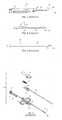
- FIG. 1is a side elevational view of a prior art biopsy device
- FIG. 3is an enlarged fragmentary view of the device of FIG. 1 showing details of the tip of the device when in a retracted position;
- FIG. 4is an exploded view of the device of FIGS. 1-3 ;
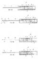
- FIG. 5is a partial sectional view showing a needle set
- FIG. 6is a side elevational view of an outer member of the needle set of FIG. 5 ;
- FIG. 7is a side elevational view of an inner member of the needle set of FIG. 5 ;
- FIG. 8is a partial side sectional view of the needle set in a retracted position
- FIGS. 9A and 9Bare partial side sectional views of the needle set of FIG. 5 in an extended position
- FIG. 10is an enlarged side elevational view of the distal end of the needle set of FIG. 5 ;
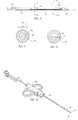
- FIG. 11is a side sectional view of the distal end of another example of a needle set
- FIG. 13is a cross sectional view of the needle set of FIG. 11 taken along line 13-13;
- FIG. 14is a perspective view of the needle set of FIG. 5 having a firing mechanism
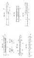
- FIGS. 15-17Bshow the construction of the inner member of FIG. 7 ;
- FIGS. 18A-18Billustrate a cross-sectional and end-view of a portion of the inner member of FIG. 7 ;
- FIGS. 18C-18Eillustrate sectional views of an embodiment of a vacuum bed formed in an inner cannula from a trocar blank
- FIGS. 19A-19Eillustrate an embodiment of a vacuum bed for use with embodiments of biopsy devices disclosed herein;
- FIG. 20Aillustrates a vacuum bed formed of a sintered or porous material blank
- FIG. 20Billustrates a vacuum bed formed of a threaded material blank
- FIG. 20Cillustrates a vacuum bed formed of a contoured material blank including threaded portions
- FIGS. 21A-21Cillustrate a vacuum bed formed of a material blank assembly having pre-drilled vacuum passages
- FIGS. 23A-23Cillustrate a vacuum bed formed of a plate material
- FIGS. 23D-23Hillustrate alternative embodiments of the vacuum bed
- FIGS 24A-24Cillustrate a vacuum bed configured from bendable tabs formed on the cannula
- FIG. 25is a cross-sectional view of an example of a double-action biopsy device
- FIGS. 26A-26Eare cross-sectional views of a second example of a double-action biopsy device
- FIG. 27is a partial cross-sectional view of another example of a double-action biopsy device of FIG. 25 ;
- FIGS. 29A-29Care cross-sectional views of a third example of a double-action biopsy device.
- FIGS. 30A-30Dare cross-sectional views of an embodiment of a double-action biopsy device according to the invention.
- FIG. 31illustrates a prespective view with a partially remove hosuing exposing an actuating platform.
- proximal and distalas used herein will be understood to describe opposite ends of a device or element, and generally will be employed so that proximal is understood as 'toward the heart' and distal is understood to mean 'away from the heart' or 'away from the practitioner' and 'toward the practitioner,' respectively.
- Figs. 5-10depict a first embodiment of a needle set 50 for a biopsy device.
- Needle set 50includes an inner member 100 slidably disposed within a lumen 58 of an outer member 60.
- Outer member 60has a tip member 61 attached to a center portion 70 and a hub member 80 positioned on the proximal end of outer member 60.
- Tip member 61has a working end 63 with an opening 63(a) therethrough, an opposite end 64 and a tip lumen 65 defined therebetween.
- center portion 70has a first end 71 hermetically connected to the opposite end 64 of the tip member 61 and a second end 73.
- a center lumen 75is defined between first and second ends 71 and 73.
- the center lumen 75is in fluid communication with the tip lumen 65.
- Hub member 80is positioned on the second end 73 of the center portion 70.
- Hub member 80defines a hub lumen 85 that is in fluid communication with the center lumen 75.
- the hub lumen 85is also in fluid communication with a pair of openings 86a, 87a defined in opposite sides 86, 87 of the hub member 80.
- a vent seal 88may be disposed within the hub member 80.
- the second end 73 of the center portion 70is attached to hub member 80 at side 86 and positioned so that the center lumen 75 is in substantial alignment with the hub lumen 85.
- a seal member 90may be positioned within the center lumen 75 and fixed to an interior surface of the center lumen 70.
- the seal member 90is any suitable seal member, such as for example, an O-ring. Seal member 90 defines an opening 91, which is in communication with the center lumen 75.
- inner member 100includes a cannula 110 and a sampling portion 150.
- Cannula 110may be slidably disposed within the center lumen 75 and through the opening 91 of the seal member 90 as shown in Fig. 5 .
- An inner lumen 115is defined between distal and proximal ends 101, 102 of corner member 100.
- Cannula 110includes an opening 120 and a vent aperture 156 that is positioned adjacent the proximal end 102. Both the opening 120 and vent aperture 156 are formed through the wall of the cannula 110 and are in fluid communication with the inner lumen 115. While opening 120 is shown as a notch, it is understood that opening 120 may take the form of other configurations.
- Sampling portion 150is attached to the distal end 101 of cannula 110.
- Sampling portion 150includes a sampling cavity 155.
- Sampling portion 150may also be provided with a tissue piercing tip 153.
- a cannula seal member 160is secured to the outer surface of the cannula 110 proximal to the opening 120.
- Cannula seal member 160is configured to movably seal within the center lumen 75 of Fig. 6 .
- the cannula seal member 160 and the seal member 90cooperate to define a vacuum chamber VC.
- the opening 120may be disposed within the vacuum chamber VC.
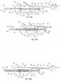
- the inner and outer members 60, 100are movable relative to one another between a retracted position in which the tip member 61 covers the sampling cavity 155 and the vacuum chamber VC is expanded, and an extended position.
- the needle setmay be placed in a cocked position as shown in FIG. 8 with the vent aperture 156 exposed to vent air A from the inner lumen 115 as the needle set is moved to the extended position (as shown in Fig. 9A ) such that movement of the outer member 60 to the distal position generates vacuum which is delivered to the inner lumen 115.
- the sampling portion 150is extended away from the tip member 61 to expose the sampling cavity 155 and the vacuum chamber VC is contracted.
- the vent aperture 156is sealed by the vent seal 88 when the needle set is completely in the extended position.
- the inner member 100As the device is cocked, the inner member 100 is pulled towards the operator, which exposes the vent aperture 156 beyond the proximal end 87 of the hub 80 of the outer cannula 60, as shown in Fig. 8 .
- the inner member 100is pushed forward to expose the cavity 155 to tissue, the vacuum chamber VC is collapsed, as indicated by the closer proximity between the cannula seal member 160 and the seal member 90. Accordingly, air A vented out through the vent aperture 156 along the direction of arrow A.
- the vent aperture 156is designed to prevent pushing air out though the cavity 155. Firing the device causes the outer member 60 to move distally, which expands the vacuum chamber VC.
- Expanding the vacuum chamber VCcreates a vacuum in the inner lumen 115, which is communicated to the cavity 155 as the vent aperture 156 is sealed within vent seal 88 disposed within the hub lumen 85.
- the vacuum generated in the extended positionserves to bias the tissue toward the sampling cavity 155 and hold the tissue in place while the suspect tissue is severed. Therefore, vacuum is applied to the tissue in cavity 155 as the tip member 61 of the outer member 60 moves over the sampling portion 150 of the inner member 100.
- the outer membertends to push tissue away from the cavity, reducing the size of the sample or requiring multiple attempts to capture the sample.
- the vacuum created by the enlargement of the vacuum chamberactually captures and holds the tissue within the cavity 155 resulting in more reliable sampling and larger sample volumes.
- the needle setmay also include a metering mechanism for selectively allowing the exchange of air but not tissue between the cavity 155 and the inner lumen 115.
- the metering mechanismincludes a filter member 180 fitted within the inner lumen 115 or disposed between the inner lumen 115 and the sampling portion 150. Any suitable material may be employed for the filter member 180. However, the selected material should, but not necessarily, have a pore size that allows the exchange of air but is too small for body tissue.
- An alternative embodiment of the metering mechanismincludes the inner member 100' shown in Figs. 11-13 .
- the distal tip member 151' of sampling portion 150'includes tissue piercing tip 153' and a solid insert 158.
- solid insert 158has an outer diameter OD that is less than the inner diameter ID of the inner lumen 115' so that air may pass around the insert 158 when the insert is disposed within the inner lumen 115'.
- the insert 158is substantially centered within the inner lumen 115'.
- the insert 158may be shifted to a particular side or portion of the inner lumen 115' thereby modifying the air flow within the inner lumen 115'.
- the insert 158 and the inner lumen 115'should be, but not necessarily, dimensioned so that the space between them allows air to pass but not tissue.
- insert 158may be attached to a connecting element 158a and a blank 151".
- insert 158is positioned within the lumen 115' of the cannula 110', with the cannula 110' friction fitted to the connecting element 158a.
- the connecting element 158acould be a ring or a pair of projections, for example.
- the sampling cavity 155'is then machined through a distal portion 101' of the cannula 110' and into the solid insert 158 to achieve the configuration shown in Figs. 17A-17B .
- the inner member 100may be inserted into the cylinder lumen 75 of the outer member 60 (as shown in Fig. 8 ).
- a tissue piercing tipcan be formed at any point in the process, using any suitable methods, such as by machining the blank 151'.
- Figs. 18A-18Billustrate an embodiment of an inner cannula 110" for use with the needle set described herein.
- the inner cannula 110"is formed having a thick exterior wall 'T' whereby the diameter of the inner lumen 115" is smaller in comparison to thin walled inner cannula 110'.
- the distal end 101" of the inner cannula 110"is disposed with a tissue piercing tip through methods known to those skilled in the art.
- a sampling cavity 155"is formed in the distal portion of the inner cannula 110" proximate the tissue piercing tip.
- the inner cannula 110"is placed in communication with a vaccuum source and a vacuum is delivered through the inner lumen 115" to the sampling cavity 155".
- Fig. 18Bgenerally illustrates a cross-sectional end-view of the inner cannula 110" after the sampling cavity 155" has been formed. A portion of the exterior wall of the inner cannula 110" is removed to expose at least a portion of the inner lumen 115".
- Figs. 18C-18Eillustrate a conventional thin walled inner cannula 110' wherein a vacuum bed 162-9 is formed by first inserting a trocar blank 164-1 into the inner lumen 115' at the distal end of the cannula 110'.
- the trocar blank 164-1includes a notch 111 at its proximal end which is formed into a vacuum port when the sampling cavity 161 is formed in the inner cannula 110'.
- the inner cannula 110'is placed in communication with a vacuum source whereby a vacuum is delivered to the inner lumen 115' to the sampling cavity 161.
- the vacuumdraws tissue into the sampling cavity 161 for excision during a biopsy procedure.
- Figs. 19A-19Eillustrate a method of configuring a vacuum bed 162-1. It is appreciated that the method illustrated is merely exemplary as other methods for configuring the vacuum beds 162-1 through 162-8 are contemplated.
- Fig. 19Aillustrates a trocar blank 164 used to form the vacuum bed 162-1. The trocar blank 164 is pressed into the distal portion 101' of the inner cannula 110'.
- the 'A' dimensionis sized to be a press-fit into the inner cannula 110' whereby it is retained by friction between itself and the lumen of the inner cannula 110'.
- the 'A' dimensionhas a flat 165 to allow for vacuum travel beneath and along the sides of the vacuum bed 162-1.
- the 'B' dimensionis sized smaller than the inner diameter of the inner cannula 110'.
- the trocar blank 164 and sampling cavity 161are ground to form the vacuum bed 162-1 such as by machining.
- the trocar blank 164then serves as the trocar tip and the vacuum bed 162-1 as illustrated in Fig. 19B.
- Figs. 19C and 19Dillustrate a vacuum channel 163 as being formed beneath and at the sides of the vacuum bed 162-1. In this fashion, the vacuum that is generated in the inner cannula 110' is uniformly distributed throughout the sampling cavity.
- Fig. 19Eillustrates a top view of the vacuum bed 162-1 after the machining process is completed.
- Fig. 20Aillustrates a vacuum bed 162-2 formed with a sintered/porous material.
- the sintered/porous blankis press-it into the inner cannula 110' and machined as described above to form the vacuum bed 162-2.
- the pores in the sintered materialallow vacuum to be pulled through the vacuum bed 162-2 and inner cannula 110', thereby pulling tissue into the sampling cavity 161.
- Fig. 20Billustrates a vacuum bed 162-3 configured from a threaded blank material
- Fig. 20Cillustrates a vacuum bed 162-4 configured from a contoured and partially threaded blank material.
- the threads in the blank materialprovide paths through which vacuum air can travel to the sampling aperture 161.
- Each of the vacuum beds (162-3 and 162-4)can be constructed in the manner described above or other method known to those skilled in the art.
- Figs. 21A-21Cillustrate a blank material subassembly used to form a vacuum bed 162-5 which contains pre-drilled vacuum passages 173.
- a trocar blank 170 and a chamber blank 172are both machined from stock material.
- the trocar blank 170is pressed into the chamber blank 172 as illustrated in Fig. 21B .
- the subassembled trocar blank 170 and chamber blank 172are then pressed into the distal end 101' of the inner cannula 110' where it is retained by friction.
- the joints between the subassembled componentscould be strengthened by laser welding the perimeter of each joint.
- Final constructionconsists of grinding the trocar blank 170 and chamber blank 172 to form a sharpened tip and vacuum bed 162-5, respectively, as illustrated in Fig. 21C .
- the vacuumis applied through the inner cannula 110' and travels through the drilled vacuum passages 173 to create a uniformly distributed vacuum at the sampling cavity 161.
- Figs. 22A and 22Billustrate a vacuum bed 162-6 formed from a framed mesh filter 176.
- the framed mesh filter 176includes substantially parallel and rigid elongated frame bars 177 which operate to support the mesh filter material 178 between disc-like end portions 179.
- the framed mesh filter 176is fixed in the inner cannula 110' by friction fit between the disc-like end portions 179 and the sampling cavity 161 (See Fig. 22B .
- the framed mesh filter 176may be spot welded at appropriate points to the inner cannula 110'.
- the disc-like end portion 179 adjacent the proximal end of the sampling cavity 161preferably includes a vacuum channel 180 which allows for vacuum in the inner cannula 110' to travel beneath the framed mesh filter 176.
- the vacuum channel 180 and framed mesh filter 176allow for delivery of vacuum to the sampling cavity 161 while preventing the extrusion of tissue down the inner cannula 110'.
- Figs. 23A through 23Eillustrate an alternative method of forming a vacuum bed 162-7 through the use of an elongated plate 182 having a plurality of weld points 184 disposed on a bottom surface thereof.
- the sampling cavity 161 and the sharpened trocar tipwill be ground on the inner cannula 110' prior to spot welding the plate 182 within the sampling cavity 161 to form the vacuum bed 162-7.
- a rod or plug 186may be inserted into the inner cannula 110' to prevent the extrusion of tissue down the inner cannula 110' (See Fig. 23B ). As best illustrated in Fig.
- the vacuum bed 162-7may include a plurality of vacuum grooves or holes 188 to aide in pulling tissue into the sampling cavity 161 via the vacuum.
- Figs. 23D-23Fillustrate an embodiment of a vacuum bed 162-7a formed using the plate 182a that includes a plurality of weld points 184a disposed on the bottom surface thereof (See Fig 23E ) and at least one elongated hole or slit 188a formed along its longitudinal axis.
- the elongated slit 188apermits a vacuum to be distributed substantially the entire length of the elongated plate 182a.
- stylaric insertsmay be disposed in the inner lumen 115' through the open distal end of the inner cannula 110' ( See Figs. 23G-23H ).
- the stylaric inserts (164-3, 164-4)are one piece structures that include a tissue piercing tip and the vacuum bed.
- the stylaric inserts (164-3, 164-4)are configured to be press fitted into the distal end of the inner cannula 110' and may be secured using an adhesive or by other methods known to those skilled in the art.
- stylaric inserts(164-3, 164-4) illustrated in Figs. 23G-23H are merely exemplary of various embodiments which would be suitable for use with biopsy devices described herein and are not intended to be limiting with respect to other configurations.
- Figs. 24A through 24Dillustrate an embodiment of a vacuum bed 162-8 configured from cut and bend tabs 190 formed in the inner cannula 110'. First the tabs 190 are cut into the inner cannula 110' and then are bent to form the vacuum bed 162-8. As best illustrated in Fig. 24B , a rod 191 may be placed inside the inner cannula 110' to prevent extrusion of tissue therethrough but allows for vacuum to be delivered to the sampling cavity 161.
- Fig. 24Cillustrates a transverse view of the vacuum bed 162-8 wherein tabs 190 are shown bent inward to vacuum slits 192 which allow vacuum to flow through the sampling cavity 161.
- Fig. 24Dillustrates a top view of the vacuum bed 162-8 providing a detailed view of the vacuum slits 192.
- Fig. 25illustrates an embodiment of a double action vacuum assisted biopsy device 200.
- the biopsy device 200provides a handpiece 201 that includes a cutting element 202 having an outer cannula 204 and an inner cannula 206.
- the outer cannula 204includes an inner lumen 208, an open proximal end 210, a tissue receiving aperture 212 disposed proximate a closed distal end 214, and a cylinder seal 216 having a central aperture 218 disposed at the open proximal end 210 thereof.
- the outer cannula 204includes a tissue piercing tip 220 that forms the closed distal end 214.
- the cylinder seal 216is fixed to the open proximal end 210 such that the central aperture 218 is preferably concentrically positioned relative to the open proximal end 210 wherein the diameter of the central aperture 218 is smaller than the diameter of the open proximal end 210.
- the cutting element 202also includes an inner cannula 206 slidably disposed within the outer cannula 204.
- the inner cannula 206is formed with an open proximal end 224 and an open distal end 226.
- the open proximal end 224is disposed with a push plate 228 having a spring collar 230 formed on a proximal side 232 thereof.
- the spring collar 230surrounds an opening 234 formed central to push plate 228.
- the opening 234has a diameter dimensioned such that the open proximal end 224 of the inner cannula 206 can be frictionally fixed therein and/or fixed therein with an adhesive suitable for such purpose.
- the open distal end 226is preferably formed with a razor sharpened beveled edge 227 that enhances the tissue cutting ability of the inner cannula 206.
- the inner cannula 206also includes an inner lumen 236 and at least one vacuum inlet 238 in fluid communication with the inner lumen 236 that is formed through the sidewall of the inner cannula 206.
- An outer diameter of the inner cannula 206is dimensioned such that it can be slidably passed through the central aperture 218 of the cylinder seal 216 while maintaining a fluid seal in relation thereto.
- the inner lumen 236also includes a vacuum seal 239 disposed proximate the open proximal end 224. The vacuum seal 239 is selectively engaged and configured to assist in maintaining a vacuum within the inner lumen 236 in a manner to be described hereinafter.
- a vacuum chamber 240is disposed about a portion of the cutting element 202 that includes the open proximal end 210 of the outer cannula 204 and cylinder seal 216, and the at least one vacuum inlet 238 of the inner cannula 206.
- the vacuum chamber 240includes an open proximal end 242 and an open distal end 244.
- the open proximal end 242 of the vacuum chamber 240has an inner diameter dimensioned to allow the inner cannula 206 to slidably pass therethrough.
- the open proximal endincludes a fluid sealing member 246 such as an O-ring that is configured to maintained a fluid seal between the inner cannula 206 and the open proximal end 242 of the vacuum chamber 240.
- the open distal end 244 of the vacuum chamber 240has an inner diameter that is dimensioned to allow the outer cannula 204 to slidably pass therethrough.
- a fluid sealing member 248is disposed at the open distal end 244 of the vacuum chamber 240 that is configured to maintain a fluid seal between the open distal end 244 of the vacuum chamber 240 and the outer cannula 204.
- the vacuum chamber 240includes an internal spring housing 250 formed about the open proximal end 242 and extending axially toward the open distal end 244.
- the internal spring housing 250is preferably formed concentric to the open proximal end 242 and is disposed with a first firing spring 252.
- the first firing spring 252includes a proximal end 254, a distal end 256, and an inner diameter that is dimensioned to allow the inner cannula 206 to pass freely therethrough.
- the first firing spring 252is disposed within the internal spring housing 250 such that the proximal end 254 contacts the open proximal end 242 of the vacuum chamber 240 and the distal end 256 contacts the cylinder seal 216.
- the vacuum chamber 240may also include a one way flow valve 257.
- the one way flow valve 257is in communication with a fluid reservoir 259 filled with an absorbent material 261.
- the fluid reservoir 259is configured to receive and retain a volume of fluid from the vacuum chamber 240 that may accumulate therein during the biopsy procedure.
- the absorbent material 261cooperates with the fluid reservoir 259 to receive and retain the volume of fluid.
- a tissue stop 258is provided and configured to be slidably received within the inner lumen 236 of the inner cannula 206 through the vacuum seal 239 disposed at the open proximal end 224 thereof.
- the tissue stop 258extends the entire length of the inner cannula 206 from the open proximal end 224 to the open distal end 226 thereof.
- the tissue stop 258includes a knob portion 260 disposed at a proximal end 262 thereof which may be used for adjusting the position of the tissue stop 258 within the inner cannula 206.
- a second firing spring 264is disposed between the knob portion 260 of the tissue stop 258 and the push plate 228 of the inner cannula 206.
- a proximal end 266 of the second firing spring 264engages the knob portion 260 and a distal end 268 engages the push plate 228 about the spring collar 230.
- the second firing spring 264is fixed to at least one of the knob portion 260 or push plate 228 to enhance the overall stability of the biopsy device 200.
- a trigger mechanism 270is provided and configured to cause the first firing spring 252 to advance the outer cannula 204 distally outwardly such that the closed proximal end 220 of the outer cannula 204 penetrates into the biopsy site.
- the second firing spring 264causes the inner cannula 206 to move distally outwardly whereby a tissue sample drawn into the tissue receiving aperture 212 is severed and retained in the inner lumen 236 of the inner cannula 206.
- the device 200before performing a biopsy precedure with the biopsy device 200, the device 200 is cocked by holding the handpiece and compressing the first and second firing springs (252, 264) until they are cocked (See Figs. 25-26B ). Thereafter, the biopsy device 200 is positioned for penetration into the biopsy site.
- the trigger mechanism 270is actuated causing the release of the first 252 firing spring.
- the cylinder seal 216 within the vacuum chamber 240is advanced forward such that it passes the at least one vacuum inlet 238 formed in the wall of the inner cannula 206.
- a vacuumis generated in the vacuum chamber 240 that is delivered to the tissue receiving aperture 212 via the inner lumen 236 of the inner cannula 206.
- the vacuumalso causes the one-way valve 257 (See Fig. 27 ) to close such that the vacuum is maintained within vacuum chamber 240.
- the vacuum seal 239is caused to engaged the tissue stop 258 such that the vacuum can be maintained at the inner lumen 236.
- the vacuum generated by the vacuum chamber 240operates to cause tissue at the biopsy site to be drawn into the tissue receiving aperture 212 thus improving the chances that a sufficent tissue sample will be obtained.
- the inner cannula 206is advanced distally outwardly by the second firing spring 264.
- the sharpened beveled edge 227 of the inner cannula 206severs the tissue drawn into the tissue receiving aperture 212 and the tissue sample is held within the inner lumen 236 of the inner cannula 206 proximate the open distal end 226 thereof by the tissue stop 258.
- itmay be configured to rotate as it is advanced distally outwardly creating a slicing and shearing action for severing the tissue.
- the tissue samplecan be retrieved from the tissue receiving aperture 212 of the outer cannula 204 by retracting the inner cannula 206 whereby the tissue sample is exposed for removal.
- the biopsy device 200is thereafter cocked causing the vacuum seal 239 and the one-way valve 257 to open whereby the vacumm is released and any fluid built up within the vacuum chamber 240 is allowed to flow into the fluid reservoir 259 (See FIG. 27 ).
- an embodiment of the biopsy device 200may be configured to cooperate with the fuild reservoir 259 being disposed in-line between the vacuum chamber 240 and a vacuum source 280.
- the vacuum source 280may be any fluid source capable of providing a vacuum to the biopsy device 200, for example, a vacuum generating machine or a CO 2 cartridge.
- the vacuum source 280communicates with the vacuum chamber 240 through tubing 282 and a vacuum port 284.
- the open proximal end 210 of the outer cannula 206is disposed with a flange 286 that seats over the internal spring housing 250 when the biopsy device 200 is cocked such that the first firing spring 252 is in mechanical communication therewith.
- the actuation of the trigger mechanism 270causes the first firing spring 252 to advance the outer cannula 204 distally outwardly and the vacuum source 280 to power on such that a vacuum is generated in the vacuum chamber 240.
- the generated vacuumis delivered to the inner cannula 206 via the at least one vacuum inlet 238.
- the vacuumcauses tissue at the biopsy site to be drawn into the tissue receiving aperture 212 of the outer cannula 204.
- the second firing spring 264causes the inner cannula 206 to be advanced distally outwardly whereby the tissue within the tissue receiving aperture 212 is severed.
- Fluid entering the vacuum chamber 240is drawn through the vacuum port 284 and tubing 282 into the fluid reservoir 259.
- the vacuum source 280is turned off and the tissue sample can be removed from the biopsy device 200 in the manner described above.
- the handpiece 300includes the vacuum port 302 in communication with a vacuum channel 304 that communicates with vacuum chamber 306.
- the vacuum port 302also communicates with a fluid reservoir 308 and vacuum source 310 through tubing 312.
- the cutting element 314includes an inner cannula 316 and an outer cannula 318 wherein a portion of the cutting element 314 is housed by the handpiece 300.
- the outer cannula 318includes open proximal 320 and distal 322 ends wherein the open distal end 322 preferably includes a razor sharpened edge 324 and the open proximal end 320 includes a second spring flange 326 formed integral thereto.
- the inner lumen 328 of the outer cannula 318includes a vent seal 330 disposed proximate the open proximal end 320 thereof.
- the inner cannula 316includes a closed proximal end 332 and a closed distal end 334 wherein the closed distal end 334 is disposed with a tissue receiving aperture 336 proximate thereto (See Fig. 29B ).
- the closed distal end 334is provided as a working end formed with a sharp tip 338 for penetrating through tissue into the biopsy site.
- the inner cannula 316includes at least one vacuum inlet 340 formed proximate the closed proximal end 332 and at least one vent aperture 342 formed between its proximal 332 and distal 334 ends.
- the closed proximal end 332includes a first spring flange 344 formed integral thereto.
- the inner lumen 346 of the inner cannula 316is disposed with a tissue stop 348 proximate a proximal end 350 of the tissue receiving aperture 336.
- the inner cannula 316is configured with an outer diameter that allows it to be slidably received into the outer cannula 318 through the vent seal 330 while maintaining a fluid seal therewith.
- the inner cannula 316passes through the vacuum chamber 306 along a longitudinal axis of the handpiece 300.
- the sidewalls of the vacuum chamber 306include seal members 352, for example, O-rings at the location where the inner cannula 316 passes along the longitudinal axis.
- the inner cannula 316has an outer diameter dimensioned to slidably pass through the seal members 352 while maintaining a fluid seal therebetween.
- the first firing spring 354is disposed about the inner cannula 316 between the first spring flange 344 and the proximal end 356 of the handpiece 300.
- the first firing spring 354operates to advance the inner cannula 316 distally outwardly into the biopsy site after the trigger mechanism 358 has been actuated.
- the second firing spring 360is disposed about the inner cannula 316 between the second spring flange 326 and the distal sidewall 362 of the vacuum chamber 306.
- the second firing spring 360causes the outer cannula 318 to be advanced distally outwardly after the inner cannula 316 has been fired (See Fig. 29C ).
- the first firing spring 354advances the inner cannula 316 distally outwardly such that the working end penetrates into the biopsy site and causes the at least one vent aperture 342 to become closed by the vent seal 330.
- the at least one vacuum inlet 340is advanced to a position within the vacuum chamber 306.
- the vacuum source 310is powered on and a vacuum is generated in the vacuum chamber 306 which is delivered to the inner cannula 316 through the vacuum inlet 340.
- the vacuum source 310may be turned on manually or automatically in response to the inner cannula 316 being fired.
- the vacuumcauses tissue to be drawn into the tissue receiving aperture 336 of the inner cannula 316 and fluid from the biopsy site to be drawn into the fluid reservoir 308.
- the outer cannula 318is advanced distally outwardly by the second firing spring 360 and the tissue drawn into the tissue receiving aperture 336 of the inner cannula 316 is severed and held in the inner lumen 346 of the inner cannula 316 proximate the tissue receiving aperture 336 by the tissue stop 348.
- the outer cannula 318may be configured to rotate while being advanced distally outwardly thereby producing a slicing and shearing action for severing the tissue at the biopsy site.
- the tissue sampleis removed by turning off the vacuum source 310 and retracting the outer cannula 318 such that the tissue sample is exposed.
- Figs. 30A-30Dillustrate another embodiment 200" of a biopsy device having a cutting element mounted to a housing.
- the biopsy device 200'includes a housing 400 having a cutting element 402.
- the cutting element 402includes an inner cannula 404 and an outer cannula 406.
- the inner cannula 404has a sharpened tip 405 formed at its distal end 414.
- a tissue receiving aperture 412is formed proximal to the sharpened tip 405 and is configured for receiving tissue to be excised in the cutting process to be described below.
- the inner cannula 404is slidably disposed wihtin the outer cannula 406.
- the outer cannula 406includes a razor sharpened beveled edge 416 formed at its distal end 418 for enhancing its ability to cut tissue.
- a vacuum chamber 408is disposed proximate the proximal end 420 of the inner cannula 404.
- the vacuum chamber 408operates to cause a vacuum to be generated in the inner cannula 404 whereby tissue to be excised is drawn into the tissue receiving aperture 412 such that the probability of obtaining an adequate sample is increased.
- a trigger mechanism 410is provided for causing the cutting element 402 to excise a tissue sample as will be described below.
- the trigger mechanism 410includes a first trigger arm 422 which causes the firing of inner cannula 404 when actuated and a second trigger arm 424 which causes the firing of the vacuum chamber 408 and, thereafter, the firing of the outer cannula 406 during the biopsy procedure.
- a biopsy procedure using the present embodimentwill be described with reference to Figs. 30A-30D.
- FIG. 30Aillustrates the biopsy device 200" wherein the inner cannula 404, outer cannula 406 and vacuum chamber 408 are retained in a cocked position by the first 422 and second 424 trigger arms of the trigger mechanism 410.
- the trigger mechanism 410is actuated to cause the first trigger arm 422 to allow the firing of the proximal end 414 of the inner cannula 404 into the biopsy site.
- the trigger mechanism 410is actuated a second time to cause the second trigger arm 424 to allow the vacuum chamber 408 to be fired. Firing of the vacuum chamber 408 causes a vacuum to be generated in the inner cannula 404 whereby tissue at the biopsy site is drawn into the tissue receiving aperture 412.
- the vacuum to be generated in the inner cannula 404as illustrated in Fig.
- the firing of the vacuum chamber 408causes the outer cannula 406 to fired whereby the tissue drawn into the tissue receiving aperture 412 is severed.
- the tissue samplemay be removed from the inner cannula 404 by pulling the outer cannula 406 back to the cocked position to expose the tissue sample.
- the biopsy deviceis moved from an uncocked position to a cocked positon by squeezing the handle 510 of the biopsy device three consecutive times to sequentially return the vacuum hub 502, the inner cannula hub 504, and the outer cannula hub 506 to the cocked position via an actuating platform 508.
- the actuating platform 508is spring loaded and slidably reciprocates between uncocked and cocked positions within the biopsy device. Squeezing the handle 510 of the biopsy device a first time causes the vacuum hub 502 to move from a uncocked position to a cocked position.
- a second squeezecauses the inner cannula hub 504 to move from a uncocked position to a cocked position and a third squeeze causes the outer cannula hub 506 to move from an uncocked position to a cocked position.
- the handle 510 of the biopsy devicemust be squeezed three times before any one core can be retrieved from the biopsy device after it has been severed.
- the assemblies of this inventioncan be provided in any suitable shape and size and can be manufactured using any suitable materials.
- the needle setis composed of surgical grade stainless steel. It is intended that the specification, drawings and examples be considered as exemplary only, with the true scope of the invention being indicated by the following claims.
Landscapes
- Health & Medical Sciences (AREA)
- Life Sciences & Earth Sciences (AREA)
- Medical Informatics (AREA)
- Engineering & Computer Science (AREA)
- Biomedical Technology (AREA)
- Heart & Thoracic Surgery (AREA)
- Pathology (AREA)
- Molecular Biology (AREA)
- Surgery (AREA)
- Animal Behavior & Ethology (AREA)
- General Health & Medical Sciences (AREA)
- Public Health (AREA)
- Veterinary Medicine (AREA)
- Surgical Instruments (AREA)
Description
- This application is a Continuation-in-Part of
U.S. Patent Application Serial No. 10/964,959 filed October 14, 2004 U.S. provisional patent application Serial No. 60/510,866 filed on October 14, 2003 - The present invention generally relates to the field of tissue sampling and harvesting. More specifically, the invention relates to biopsy needle sets and devices.
- In the practice of diagnostic medicine, it is often necessary or desirable to perform a biopsy, or to sample selected tissue from a living patient for medical evaluation. Cytological and histological studies of the biopsy sample can then be performed as an aid to the diagnosis and treatment of disease. Biopsies can be useful in diagnosing and treating various forms of cancer, as well as other diseases in which a localized area of affected tissue can be identified.
- Biopsies are routinely performed on tissue using a needle set, which typically includes a stylet with a pointed tip and a notch defined near its distal end. The stylet is slidably disposed within a cannula so that the notch can be alternately exposed or covered. Typically, a hub is connected to the proximal end of each needle. Such needle sets are used with or incorporated in various forms of biopsy devices, such as the single action and double action biopsy devices. One such needle set is incorporated into the single action biopsy device shown in
Figs. 1-4 . - Referring to
Figs. 1-4 , singleaction biopsy device 20 includes an outerhollow needle 22 defining alumen 24 therethrough. Astylet 26 is slidingly disposed withinlumen 24 and is moveable relative toouter needle 22. A first ordistal end 28 ofstylet 26 is provided with a tissue cutting-point 30 and acavity 32 adjacent tofirst end 28 for receiving tissue samples.Stylet 26 is slidable relative toouter needle 22 between a first or retracted position (Fig. 3 ) and a second or extended position (Fig. 2 ). - In the first position,
stylet 26 is retracted withinlumen 24 so thatouter needle 22 coverscavity 32. In the second position, thefirst end 28 ofstylet 26 is extended away fromouter needle 22 to exposecavity 32 to tissues at the biopsy site. - During a biopsy procedure,
device 20 will be positioned with thecavity 32 at the targeted site for the biopsy.Stylet 26 is momentarily driven into the tissue far enough to exposecavity 32. Tissue then prolapses intocavity 32. The device is then fired to advanceouter needle 22 alongstylet 26 to covercavity 32. This forward movement ofouter needle 22 severs the prolapsed tissue to obtain a tissue sample, which becomes trapped incavity 32 ofstylet 26. Withouter needle 22 blocking the opening ofcavity 32,biopsy device 20 is then withdrawn from the target site, carrying the sample withincavity 32. To collect the biopsy sample,outer needle 22 is once again retracted to exposecavity 32 ofstylet 26. The procedure may be repeated several times until satisfactory samples have been obtained. - The
firing mechanism 40 for such known single action biopsy devices is shown inFig. 4 .Firing mechanism 40 includes ahousing 27 havingfinger grips actuator 43 is operatively engaged with both the stylet 26 andouter needle 22.Actuator 43 includes agripping portion 44 and a drive mechanism 45. Drive mechanism 45 operates to depress a drive carriage 46 against the action of aspring 35.Housing 27 includes aresilient latch 36 that engages an underside 47 of the carriage 46 in the retracted position. Latch 36 is released by forward movement of the drive mechanism 45 so that thespring 35 urges carriage 46 outwardly, which in turn thrustsouter needle 22 over thesampling cavity 32 of thestylet 26. Cover 49 snap-fits overhousing 27 to protectspring 35 and the sliding engagement between carriage 46 and housing 27 from debris and interference. - Double action biopsy devices also employ similar needle sets. In a double action biopsy device, movement of inner and
outer needles proximal ends 29 ofneedles U.S. Pat. No. 5,538,010 . - A further vacuum assisted biopsy device is disclosed in
WO 02/22023 A - While these single and double action biopsy devices are widely used, a basic problem remains in the field of biopsy, which is the need to obtain a sufficient amount of sample tissue. One potential cause of the problem is that as the outer needle passes over the tissue cavity, the outer needle has a tendency to push the tissue away from the cavity. This results in samples that are inferior in quality or too small, which precludes the pathologist from conclusively determining whether disease is present, and if so, to what extent it has progressed. The pathologist must then issue an inconclusive diagnostic report. This causes the physician to recall the patient and attempt another needle biopsy, or in some situations, the patient is scheduled for a more invasive, traumatic and expensive procedure such as an open surgical biopsy.
- The challenge has been to consistently obtain sufficient tissue volume and quality tissue cores, regardless of tissue type, to meet the needs of the pathologist so that a conclusive diagnosis can be achieved. Therefore, a need remains for advice that can consistently achieve this result.
- The invention is defined in claim 1 while preferred embodiments are set forth in the dependent claims.
- A biopsy device having a cutting element is disclosed. The cutting element includes an outer cannula having a tissue receving aperture disposed proximate a distal end thereof and an inner lumen. An inner cannula is slidably disposed within the inner lumen of the outer cannula. The inner cannula also has an inner lumen and includes an open distal end defined by a sharpened circumferential edge. A vacuum chamber is disposed about at least a portion of the cutting element and is configured to create a vacuum in the cutting element during a biopsy procedure. The outer cannula is advanced distally outwardly to cause the vacuum to be generated in the vacuum chamber and delivered to the cutting element whereby tissue is drawn into the tissue receiving aperture. The inner cannula is then advanced distally outwardly after the outer cannula such that tissue drawn into the tissue cutting aperture is severed.
- A trigger operates to first cause the inner cannula to be advanced distally outwardly and to cause a vacuum to be generated such that tissue is drawn into a tissue receiving aperture formed in the inner cannula. Thereafter, the outer cannula is advanced distally outwardly such that tissue drawn into the tissue receiving aperture is severed.
- In at least one other embodiment of the biopsy device, a vacuum bed is formed at the distal end of the inner cannula for providing a uniform vacuum throughout the tissue receiving aperture. A trocar blank is inserted into the distal end of the inner cannula which is then ground or machined to form the vacuum bed. The vacuum bed includes at least one vacuum channel or aperture which operates to uniformly distributes vacuum air over the entire vacuum bed.
- Embodiments of the invention are illustrated in the
figures 18C-24D and 30A-30D. - Further examples described below and illustrated in the other figures do not form part of the invention but provide information that is useful for understanding the invention.
FIG. 1 is a side elevational view of a prior art biopsy device;FIG. 2 is an enlarged fragmentary view of the device ofFIG. 1 , showing details of the tip of the device when in an extended position;FIG. 3 is an enlarged fragmentary view of the device ofFIG. 1 showing details of the tip of the device when in a retracted position;FIG. 4 is an exploded view of the device ofFIGS. 1-3 ;FIG. 5 is a partial sectional view showing a needle set;FIG. 6 is a side elevational view of an outer member of the needle set ofFIG. 5 ;FIG. 7 is a side elevational view of an inner member of the needle set ofFIG. 5 ;FIG. 8 is a partial side sectional view of the needle set in a retracted position;FIGS. 9A and9B are partial side sectional views of the needle set ofFIG. 5 in an extended position;FIG. 10 is an enlarged side elevational view of the distal end of the needle set ofFIG. 5 ;FIG. 11 is a side sectional view of the distal end of another example of a needle set;FIG. 12 is a cross sectional view of the needle set ofFIG. 11 taken along line 12-12 ofFIG. 11 ;FIG. 13 is a cross sectional view of the needle set ofFIG. 11 taken along line 13-13;FIG. 14 is a perspective view of the needle set ofFIG. 5 having a firing mechanism;FIGS. 15-17B show the construction of the inner member ofFIG. 7 ;FIGS. 18A-18B illustrate a cross-sectional and end-view of a portion of the inner member ofFIG. 7 ;FIGS. 18C-18E illustrate sectional views of an embodiment of a vacuum bed formed in an inner cannula from a trocar blank;FIGS. 19A-19E illustrate an embodiment of a vacuum bed for use with embodiments of biopsy devices disclosed herein;FIG. 20A illustrates a vacuum bed formed of a sintered or porous material blank;FIG. 20B illustrates a vacuum bed formed of a threaded material blank;FIG. 20C illustrates a vacuum bed formed of a contoured material blank including threaded portions;FIGS. 21A-21C illustrate a vacuum bed formed of a material blank assembly having pre-drilled vacuum passages;FIGS. 22A and 22B illustrate a vacuum bed formed from a framed mesh filter;FIGS. 23A-23C illustrate a vacuum bed formed of a plate material;FIGS. 23D-23H illustrate alternative embodiments of the vacuum bed;FIGS 24A-24C illustrate a vacuum bed configured from bendable tabs formed on the cannula;FIG. 25 is a cross-sectional view of an example of a double-action biopsy device;FIGS. 26A-26E are cross-sectional views of a second example of a double-action biopsy device;FIG. 27 is a partial cross-sectional view of another example of a double-action biopsy device ofFIG. 25 ;FIG. 28 is a partial cross-sectional view of yet another example of a double-action biopsy device ofFIG. 25 ;FIGS. 29A-29C are cross-sectional views of a third example of a double-action biopsy device;FIGS. 30A-30D are cross-sectional views of an embodiment of a double-action biopsy device according to the invention; and;FIG. 31 illustrates a prespective view with a partially remove hosuing exposing an actuating platform.- Although the drawings represent embodiments of the present invention, the drawings are not necessarily to scale and certain features may be exaggerated in order to better illustrate and explain the present invention. The exemplification set out herein illustrates certain embodiments of the invention, in one, or more forms, and such exemplifications are not to be construed as limiting the scope of the invention in any manner.
- For the purposes of promoting an understanding of the principles of the invention, reference will now be made to the embodiments illustrated in the drawings and specific language will be used to describe the same. It will nevertheless be understood that no limitation of the scope of the invention is thereby intended.
- The terms proximal and distal as used herein will be understood to describe opposite ends of a device or element, and generally will be employed so that proximal is understood as 'toward the heart' and distal is understood to mean 'away from the heart' or 'away from the practitioner' and 'toward the practitioner,' respectively.
Figs. 5-10 depict a first embodiment of a needle set 50 for a biopsy device. Needle set 50 includes aninner member 100 slidably disposed within a lumen 58 of anouter member 60.Outer member 60 has atip member 61 attached to acenter portion 70 and ahub member 80 positioned on the proximal end ofouter member 60.Tip member 61 has a workingend 63 with an opening 63(a) therethrough, anopposite end 64 and atip lumen 65 defined therebetween. As seen most clearly inFig. 6 ,center portion 70 has afirst end 71 hermetically connected to theopposite end 64 of thetip member 61 and asecond end 73. Acenter lumen 75 is defined between first and second ends 71 and 73. Thecenter lumen 75 is in fluid communication with thetip lumen 65.Hub member 80 is positioned on thesecond end 73 of thecenter portion 70.Hub member 80 defines ahub lumen 85 that is in fluid communication with thecenter lumen 75. Thehub lumen 85 is also in fluid communication with a pair ofopenings opposite sides hub member 80. Avent seal 88 may be disposed within thehub member 80. Thesecond end 73 of thecenter portion 70 is attached tohub member 80 atside 86 and positioned so that thecenter lumen 75 is in substantial alignment with thehub lumen 85.- A
seal member 90 may be positioned within thecenter lumen 75 and fixed to an interior surface of thecenter lumen 70. Theseal member 90 is any suitable seal member, such as for example, an O-ring.Seal member 90 defines anopening 91, which is in communication with thecenter lumen 75. - Referring now to
Fig. 7 ,inner member 100 includes acannula 110 and asampling portion 150.Cannula 110 may be slidably disposed within thecenter lumen 75 and through theopening 91 of theseal member 90 as shown inFig. 5 . Aninner lumen 115 is defined between distal and proximal ends 101, 102 ofcorner member 100.Cannula 110 includes anopening 120 and avent aperture 156 that is positioned adjacent theproximal end 102. Both theopening 120 and ventaperture 156 are formed through the wall of thecannula 110 and are in fluid communication with theinner lumen 115. While opening 120 is shown as a notch, it is understood that opening 120 may take the form of other configurations. Sampling portion 150 is attached to thedistal end 101 ofcannula 110.Sampling portion 150 includes asampling cavity 155.Sampling portion 150 may also be provided with atissue piercing tip 153. Acannula seal member 160 is secured to the outer surface of thecannula 110 proximal to theopening 120.Cannula seal member 160 is configured to movably seal within thecenter lumen 75 ofFig. 6 .- As shown in
Fig. 8 , thecannula seal member 160 and theseal member 90 cooperate to define a vacuum chamber VC. Theopening 120 may be disposed within the vacuum chamber VC. The inner andouter members tip member 61 covers thesampling cavity 155 and the vacuum chamber VC is expanded, and an extended position. The needle set may be placed in a cocked position as shown inFIG. 8 with thevent aperture 156 exposed to vent air A from theinner lumen 115 as the needle set is moved to the extended position (as shown inFig. 9A ) such that movement of theouter member 60 to the distal position generates vacuum which is delivered to theinner lumen 115. In the extended position thesampling portion 150 is extended away from thetip member 61 to expose thesampling cavity 155 and the vacuum chamber VC is contracted. Thevent aperture 156 is sealed by thevent seal 88 when the needle set is completely in the extended position. - As the device is cocked, the
inner member 100 is pulled towards the operator, which exposes thevent aperture 156 beyond theproximal end 87 of thehub 80 of theouter cannula 60, as shown inFig. 8 . Referring toFig. 9B , theinner member 100 is pushed forward to expose thecavity 155 to tissue, the vacuum chamber VC is collapsed, as indicated by the closer proximity between thecannula seal member 160 and theseal member 90. Accordingly, air A vented out through thevent aperture 156 along the direction of arrow A. Thevent aperture 156 is designed to prevent pushing air out though thecavity 155. Firing the device causes theouter member 60 to move distally, which expands the vacuum chamber VC. Expanding the vacuum chamber VC creates a vacuum in theinner lumen 115, which is communicated to thecavity 155 as thevent aperture 156 is sealed withinvent seal 88 disposed within thehub lumen 85. The vacuum generated in the extended position serves to bias the tissue toward thesampling cavity 155 and hold the tissue in place while the suspect tissue is severed. Therefore, vacuum is applied to the tissue incavity 155 as thetip member 61 of theouter member 60 moves over thesampling portion 150 of theinner member 100. In contrast, when prior art devices are used, the outer member tends to push tissue away from the cavity, reducing the size of the sample or requiring multiple attempts to capture the sample. In the embodiments of the present invention, the vacuum created by the enlargement of the vacuum chamber actually captures and holds the tissue within thecavity 155 resulting in more reliable sampling and larger sample volumes. - The needle set may also include a metering mechanism for selectively allowing the exchange of air but not tissue between the
cavity 155 and theinner lumen 115. As shown more clearly inFig. 10 , in one particular embodiment, the metering mechanism includes afilter member 180 fitted within theinner lumen 115 or disposed between theinner lumen 115 and thesampling portion 150. Any suitable material may be employed for thefilter member 180. However, the selected material should, but not necessarily, have a pore size that allows the exchange of air but is too small for body tissue. - An alternative embodiment of the metering mechanism includes the inner member 100' shown in
Figs. 11-13 . The distal tip member 151' of sampling portion 150' includes tissue piercing tip 153' and asolid insert 158. As illustrated byFigs. 12-13 ,solid insert 158 has an outer diameter OD that is less than the inner diameter ID of the inner lumen 115' so that air may pass around theinsert 158 when the insert is disposed within the inner lumen 115'. As shown, theinsert 158 is substantially centered within the inner lumen 115'. In alternate embodiments, based on design requirements, theinsert 158 may be shifted to a particular side or portion of the inner lumen 115' thereby modifying the air flow within the inner lumen 115'. Theinsert 158 and the inner lumen 115' should be, but not necessarily, dimensioned so that the space between them allows air to pass but not tissue. - The needle set embodiments herein may be operated via a biopsy device. For example, the needle set can be loaded into a double action biopsy device or incorporated into a single action biopsy device.
Fig. 14 illustrates a needle set including an advancingmechanism 159, operatively engaged to thesecond end 73 of thecylinder 70 and theproximal end 102 of theinner member 100. The advancingmechanism 159 is operable to move theouter member 60 relative to theinner member 100 from the second position to the first position to trap tissue from the biopsy site in thesampling cavity 155. - The embodiments of the
inner member 100 described herein may be constructed according to the steps depicted inFigs. 15-18 . As shown inFig. 15 , insert 158 may be attached to a connectingelement 158a and a blank 151". As shown inFig. 16 ,insert 158 is positioned within the lumen 115' of the cannula 110', with the cannula 110' friction fitted to the connectingelement 158a. The connectingelement 158a could be a ring or a pair of projections, for example. The sampling cavity 155' is then machined through a distal portion 101' of the cannula 110' and into thesolid insert 158 to achieve the configuration shown inFigs. 17A-17B . Theinner member 100 may be inserted into thecylinder lumen 75 of the outer member 60 (as shown inFig. 8 ). A tissue piercing tip can be formed at any point in the process, using any suitable methods, such as by machining the blank 151'. Figs. 18A-18B illustrate an embodiment of aninner cannula 110" for use with the needle set described herein. Theinner cannula 110" is formed having a thick exterior wall 'T' whereby the diameter of theinner lumen 115" is smaller in comparison to thin walled inner cannula 110'. Thedistal end 101" of theinner cannula 110" is disposed with a tissue piercing tip through methods known to those skilled in the art. Asampling cavity 155" is formed in the distal portion of theinner cannula 110" proximate the tissue piercing tip. Theinner cannula 110" is placed in communication with a vaccuum source and a vacuum is delivered through theinner lumen 115" to thesampling cavity 155". The vacuum causes tissue at the biopsy site to be drawn into thesampling cavity 155" for excision during a biopsy procedure.Fig. 18B generally illustrates a cross-sectional end-view of theinner cannula 110" after thesampling cavity 155" has been formed. A portion of the exterior wall of theinner cannula 110" is removed to expose at least a portion of theinner lumen 115".Figs. 18C-18E illustrate a conventional thin walled inner cannula 110' wherein a vacuum bed 162-9 is formed by first inserting a trocar blank 164-1 into the inner lumen 115' at the distal end of the cannula 110'. The trocar blank 164-1 includes anotch 111 at its proximal end which is formed into a vacuum port when thesampling cavity 161 is formed in the inner cannula 110'. The inner cannula 110' is placed in communication with a vacuum source whereby a vacuum is delivered to the inner lumen 115' to thesampling cavity 161. The vacuum draws tissue into thesampling cavity 161 for excision during a biopsy procedure.Figs. 19-24 illustrate alternative embodiments wherein the distal portion 101' of the inner cannula 110' is configured as a vacuum bed (162-1 through 162-8). The vacuum beds (162-1 through 162-8) are configured to provide a uniform vacuum throughout thesampling cavity 161 in order to acquire more uniform and larger core samples. Additionally, the vacuum bed (162-1 through 162-8) operates to provide rigidity to the bottom of the inner cannula 110' which also allows for adeeper sampling cavity 161 to be formed.Figs. 19A-19E illustrate a method of configuring a vacuum bed 162-1. It is appreciated that the method illustrated is merely exemplary as other methods for configuring the vacuum beds 162-1 through 162-8 are contemplated.Fig. 19A illustrates a trocar blank 164 used to form the vacuum bed 162-1. Thetrocar blank 164 is pressed into the distal portion 101' of the inner cannula 110'. The 'A' dimension is sized to be a press-fit into the inner cannula 110' whereby it is retained by friction between itself and the lumen of the inner cannula 110'. In addition, the 'A' dimension has a flat 165 to allow for vacuum travel beneath and along the sides of the vacuum bed 162-1. The 'B' dimension is sized smaller than the inner diameter of the inner cannula 110'. Once pressed into the inner cannula 110', thetrocar blank 164 andsampling cavity 161 are ground to form the vacuum bed 162-1 such as by machining. The trocar blank 164 then serves as the trocar tip and the vacuum bed 162-1 as illustrated inFig. 19B. Figs. 19C and 19D illustrate avacuum channel 163 as being formed beneath and at the sides of the vacuum bed 162-1. In this fashion, the vacuum that is generated in the inner cannula 110' is uniformly distributed throughout the sampling cavity.Fig. 19E illustrates a top view of the vacuum bed 162-1 after the machining process is completed.Fig. 20A illustrates a vacuum bed 162-2 formed with a sintered/porous material. The sintered/porous blank is press-it into the inner cannula 110' and machined as described above to form the vacuum bed 162-2. The pores in the sintered material allow vacuum to be pulled through the vacuum bed 162-2 and inner cannula 110', thereby pulling tissue into thesampling cavity 161.Fig. 20B illustrates a vacuum bed 162-3 configured from a threaded blank material andFig. 20C illustrates a vacuum bed 162-4 configured from a contoured and partially threaded blank material. The threads in the blank material provide paths through which vacuum air can travel to thesampling aperture 161. Each of the vacuum beds (162-3 and 162-4) can be constructed in the manner described above or other method known to those skilled in the art.Figs. 21A-21C illustrate a blank material subassembly used to form a vacuum bed 162-5 which containspre-drilled vacuum passages 173. Atrocar blank 170 and a chamber blank 172 are both machined from stock material. Thetrocar blank 170 is pressed into the chamber blank 172 as illustrated inFig. 21B . The subassembled trocar blank 170 and chamber blank 172 are then pressed into the distal end 101' of the inner cannula 110' where it is retained by friction. Also, the joints between the subassembled components could be strengthened by laser welding the perimeter of each joint. Final construction consists of grinding thetrocar blank 170 and chamber blank 172 to form a sharpened tip and vacuum bed 162-5, respectively, as illustrated inFig. 21C . The vacuum is applied through the inner cannula 110' and travels through the drilledvacuum passages 173 to create a uniformly distributed vacuum at thesampling cavity 161.Figs. 22A and 22B illustrate a vacuum bed 162-6 formed from a framedmesh filter 176. The framedmesh filter 176 includes substantially parallel and rigid elongated frame bars 177 which operate to support themesh filter material 178 between disc-like end portions 179. The framedmesh filter 176 is fixed in the inner cannula 110' by friction fit between the disc-like end portions 179 and the sampling cavity 161 (SeeFig. 22B . Alternatively, the framedmesh filter 176 may be spot welded at appropriate points to the inner cannula 110'. The disc-like end portion 179 adjacent the proximal end of thesampling cavity 161 preferably includes avacuum channel 180 which allows for vacuum in the inner cannula 110' to travel beneath the framedmesh filter 176. Thevacuum channel 180 and framedmesh filter 176 allow for delivery of vacuum to thesampling cavity 161 while preventing the extrusion of tissue down the inner cannula 110'.Figs. 23A through 23E illustrate an alternative method of forming a vacuum bed 162-7 through the use of anelongated plate 182 having a plurality of weld points 184 disposed on a bottom surface thereof. In this embodiment, thesampling cavity 161 and the sharpened trocar tip will be ground on the inner cannula 110' prior to spot welding theplate 182 within thesampling cavity 161 to form the vacuum bed 162-7. A rod or plug 186 may be inserted into the inner cannula 110' to prevent the extrusion of tissue down the inner cannula 110' (SeeFig. 23B ). As best illustrated inFig. 23C , the vacuum bed 162-7 may include a plurality of vacuum grooves or holes 188 to aide in pulling tissue into thesampling cavity 161 via the vacuum.Figs. 23D-23F illustrate an embodiment of a vacuum bed 162-7a formed using theplate 182a that includes a plurality ofweld points 184a disposed on the bottom surface thereof (SeeFig 23E ) and at least one elongated hole or slit 188a formed along its longitudinal axis. Theelongated slit 188a permits a vacuum to be distributed substantially the entire length of theelongated plate 182a. In addition to the forming the vacuum beds (162-7, 162-7a) using the respective elongated plates (182, 182a), stylaric inserts (164-3, 164-4) may be disposed in the inner lumen 115' through the open distal end of the inner cannula 110' ( SeeFigs. 23G-23H ). The stylaric inserts (164-3, 164-4) are one piece structures that include a tissue piercing tip and the vacuum bed. The stylaric inserts (164-3, 164-4) are configured to be press fitted into the distal end of the inner cannula 110' and may be secured using an adhesive or by other methods known to those skilled in the art. It is appreciated that the stylaric inserts (164-3, 164-4) illustrated inFigs. 23G-23H are merely exemplary of various embodiments which would be suitable for use with biopsy devices described herein and are not intended to be limiting with respect to other configurations.Figs. 24A through 24D illustrate an embodiment of a vacuum bed 162-8 configured from cut andbend tabs 190 formed in the inner cannula 110'. First thetabs 190 are cut into the inner cannula 110' and then are bent to form the vacuum bed 162-8. As best illustrated inFig. 24B , arod 191 may be placed inside the inner cannula 110' to prevent extrusion of tissue therethrough but allows for vacuum to be delivered to thesampling cavity 161.Fig. 24C illustrates a transverse view of the vacuum bed 162-8 whereintabs 190 are shown bent inward to vacuumslits 192 which allow vacuum to flow through thesampling cavity 161.Fig. 24D illustrates a top view of the vacuum bed 162-8 providing a detailed view of the vacuum slits 192.Fig. 25 illustrates an embodiment of a double action vacuum assistedbiopsy device 200. Thebiopsy device 200 provides ahandpiece 201 that includes acutting element 202 having anouter cannula 204 and aninner cannula 206. Theouter cannula 204 includes aninner lumen 208, an openproximal end 210, atissue receiving aperture 212 disposed proximate a closeddistal end 214, and acylinder seal 216 having acentral aperture 218 disposed at the openproximal end 210 thereof. Preferably, theouter cannula 204 includes atissue piercing tip 220 that forms the closeddistal end 214. Thecylinder seal 216 is fixed to the openproximal end 210 such that thecentral aperture 218 is preferably concentrically positioned relative to the openproximal end 210 wherein the diameter of thecentral aperture 218 is smaller than the diameter of the openproximal end 210.- The cutting
element 202 also includes aninner cannula 206 slidably disposed within theouter cannula 204. Theinner cannula 206 is formed with an openproximal end 224 and an opendistal end 226. The openproximal end 224 is disposed with apush plate 228 having a spring collar 230 formed on aproximal side 232 thereof. The spring collar 230 surrounds anopening 234 formed central to pushplate 228. Theopening 234 has a diameter dimensioned such that the openproximal end 224 of theinner cannula 206 can be frictionally fixed therein and/or fixed therein with an adhesive suitable for such purpose. - The open
distal end 226 is preferably formed with a razor sharpenedbeveled edge 227 that enhances the tissue cutting ability of theinner cannula 206. Theinner cannula 206 also includes aninner lumen 236 and at least onevacuum inlet 238 in fluid communication with theinner lumen 236 that is formed through the sidewall of theinner cannula 206. An outer diameter of theinner cannula 206 is dimensioned such that it can be slidably passed through thecentral aperture 218 of thecylinder seal 216 while maintaining a fluid seal in relation thereto. Theinner lumen 236 also includes avacuum seal 239 disposed proximate the openproximal end 224. Thevacuum seal 239 is selectively engaged and configured to assist in maintaining a vacuum within theinner lumen 236 in a manner to be described hereinafter. - A
vacuum chamber 240 is disposed about a portion of the cuttingelement 202 that includes the openproximal end 210 of theouter cannula 204 andcylinder seal 216, and the at least onevacuum inlet 238 of theinner cannula 206. Thevacuum chamber 240 includes an openproximal end 242 and an opendistal end 244. The openproximal end 242 of thevacuum chamber 240 has an inner diameter dimensioned to allow theinner cannula 206 to slidably pass therethrough. Preferably, the open proximal end includes afluid sealing member 246 such as an O-ring that is configured to maintained a fluid seal between theinner cannula 206 and the openproximal end 242 of thevacuum chamber 240. The opendistal end 244 of thevacuum chamber 240 has an inner diameter that is dimensioned to allow theouter cannula 204 to slidably pass therethrough. Preferably, afluid sealing member 248 is disposed at the opendistal end 244 of thevacuum chamber 240 that is configured to maintain a fluid seal between the opendistal end 244 of thevacuum chamber 240 and theouter cannula 204. - The
vacuum chamber 240 includes aninternal spring housing 250 formed about the openproximal end 242 and extending axially toward the opendistal end 244. Theinternal spring housing 250 is preferably formed concentric to the openproximal end 242 and is disposed with afirst firing spring 252. Thefirst firing spring 252 includes aproximal end 254, adistal end 256, and an inner diameter that is dimensioned to allow theinner cannula 206 to pass freely therethrough. Thefirst firing spring 252 is disposed within theinternal spring housing 250 such that theproximal end 254 contacts the openproximal end 242 of thevacuum chamber 240 and thedistal end 256 contacts thecylinder seal 216. - As best illustrated in
Fig. 27 , thevacuum chamber 240 may also include a oneway flow valve 257. The oneway flow valve 257 is in communication with afluid reservoir 259 filled with an absorbent material 261. Thefluid reservoir 259 is configured to receive and retain a volume of fluid from thevacuum chamber 240 that may accumulate therein during the biopsy procedure. The absorbent material 261 cooperates with thefluid reservoir 259 to receive and retain the volume of fluid. - Referring again to
Fig. 26 , atissue stop 258 is provided and configured to be slidably received within theinner lumen 236 of theinner cannula 206 through thevacuum seal 239 disposed at the openproximal end 224 thereof. In one embodiment, thetissue stop 258 extends the entire length of theinner cannula 206 from the openproximal end 224 to the opendistal end 226 thereof. Thetissue stop 258 includes aknob portion 260 disposed at aproximal end 262 thereof which may be used for adjusting the position of thetissue stop 258 within theinner cannula 206. - A
second firing spring 264 is disposed between theknob portion 260 of thetissue stop 258 and thepush plate 228 of theinner cannula 206. A proximal end 266 of thesecond firing spring 264 engages theknob portion 260 and adistal end 268 engages thepush plate 228 about the spring collar 230. Preferably, thesecond firing spring 264 is fixed to at least one of theknob portion 260 or pushplate 228 to enhance the overall stability of thebiopsy device 200. - A
trigger mechanism 270 is provided and configured to cause thefirst firing spring 252 to advance theouter cannula 204 distally outwardly such that the closedproximal end 220 of theouter cannula 204 penetrates into the biopsy site. Shortly therafter, thesecond firing spring 264 causes theinner cannula 206 to move distally outwardly whereby a tissue sample drawn into thetissue receiving aperture 212 is severed and retained in theinner lumen 236 of theinner cannula 206. - Referring now to
Figs. 25 and26A through 26E , before performing a biopsy precedure with thebiopsy device 200, thedevice 200 is cocked by holding the handpiece and compressing the first and second firing springs (252, 264) until they are cocked (SeeFigs. 25-26B ). Thereafter, thebiopsy device 200 is positioned for penetration into the biopsy site. - Next at
Fig. 26C , thetrigger mechanism 270 is actuated causing the release of the first 252 firing spring. When theouter cannula 204 is advance distally outwardly by thefirst firing spring 252 into the biopsy site, thecylinder seal 216 within thevacuum chamber 240 is advanced forward such that it passes the at least onevacuum inlet 238 formed in the wall of theinner cannula 206. Once thecylinder seal 216 passes the at least onevacuum inlet 238, a vacuum is generated in thevacuum chamber 240 that is delivered to thetissue receiving aperture 212 via theinner lumen 236 of theinner cannula 206. The vacuum also causes the one-way valve 257 (SeeFig. 27 ) to close such that the vacuum is maintained withinvacuum chamber 240. Further, thevacuum seal 239 is caused to engaged the tissue stop 258 such that the vacuum can be maintained at theinner lumen 236. The vacuum generated by thevacuum chamber 240 operates to cause tissue at the biopsy site to be drawn into thetissue receiving aperture 212 thus improving the chances that a sufficent tissue sample will be obtained. - Referring now to
Fig. 26D , a short predetermined period after theouter cannula 204 has been fired, theinner cannula 206 is advanced distally outwardly by thesecond firing spring 264. The sharpened bevelededge 227 of theinner cannula 206 severs the tissue drawn into thetissue receiving aperture 212 and the tissue sample is held within theinner lumen 236 of theinner cannula 206 proximate the opendistal end 226 thereof by thetissue stop 258. To further enhance to cutting ability of theinner cannula 206, it may be configured to rotate as it is advanced distally outwardly creating a slicing and shearing action for severing the tissue. - Referring now to
Fig. 26E , after removing thebiopsy device 200 from the biopsy site, the tissue sample can be retrieved from thetissue receiving aperture 212 of theouter cannula 204 by retracting theinner cannula 206 whereby the tissue sample is exposed for removal. Thebiopsy device 200 is thereafter cocked causing thevacuum seal 239 and the one-way valve 257 to open whereby the vacumm is released and any fluid built up within thevacuum chamber 240 is allowed to flow into the fluid reservoir 259 (SeeFIG. 27 ). - As best illustrated in
Fig. 28 , an embodiment of thebiopsy device 200 may be configured to cooperate with thefuild reservoir 259 being disposed in-line between thevacuum chamber 240 and avacuum source 280. Thevacuum source 280 may be any fluid source capable of providing a vacuum to thebiopsy device 200, for example, a vacuum generating machine or a CO2 cartridge. Preferably, thevacuum source 280 communicates with thevacuum chamber 240 throughtubing 282 and avacuum port 284. In this embodiment, the openproximal end 210 of theouter cannula 206 is disposed with aflange 286 that seats over theinternal spring housing 250 when thebiopsy device 200 is cocked such that thefirst firing spring 252 is in mechanical communication therewith. Preferably, the actuation of thetrigger mechanism 270 causes thefirst firing spring 252 to advance theouter cannula 204 distally outwardly and thevacuum source 280 to power on such that a vacuum is generated in thevacuum chamber 240. The generated vacuum is delivered to theinner cannula 206 via the at least onevacuum inlet 238. The vacuum causes tissue at the biopsy site to be drawn into thetissue receiving aperture 212 of theouter cannula 204. Thereafter, thesecond firing spring 264 causes theinner cannula 206 to be advanced distally outwardly whereby the tissue within thetissue receiving aperture 212 is severed. Fluid entering thevacuum chamber 240 is drawn through thevacuum port 284 andtubing 282 into thefluid reservoir 259. After the tissue sample has been obtained thevacuum source 280 is turned off and the tissue sample can be removed from thebiopsy device 200 in the manner described above. - Another embodiment 200' of the biopsy device is configured to allow the
inner cannula 206 to be fired prior to firing theouter cannula 204. In the embodimentFigs. 29A through 29C , thehandpiece 300 includes thevacuum port 302 in communication with avacuum channel 304 that communicates withvacuum chamber 306. Thevacuum port 302 also communicates with afluid reservoir 308 andvacuum source 310 throughtubing 312. The cuttingelement 314 includes aninner cannula 316 and anouter cannula 318 wherein a portion of the cuttingelement 314 is housed by thehandpiece 300. Theouter cannula 318 includes open proximal 320 and distal 322 ends wherein the opendistal end 322 preferably includes a razor sharpenededge 324 and the openproximal end 320 includes asecond spring flange 326 formed integral thereto. Theinner lumen 328 of theouter cannula 318 includes avent seal 330 disposed proximate the openproximal end 320 thereof. - The
inner cannula 316 includes a closedproximal end 332 and a closeddistal end 334 wherein the closeddistal end 334 is disposed with atissue receiving aperture 336 proximate thereto (SeeFig. 29B ). The closeddistal end 334 is provided as a working end formed with asharp tip 338 for penetrating through tissue into the biopsy site. Theinner cannula 316 includes at least onevacuum inlet 340 formed proximate the closedproximal end 332 and at least onevent aperture 342 formed between its proximal 332 and distal 334 ends. The closedproximal end 332 includes afirst spring flange 344 formed integral thereto. Preferably, theinner lumen 346 of theinner cannula 316 is disposed with atissue stop 348 proximate aproximal end 350 of thetissue receiving aperture 336. Theinner cannula 316 is configured with an outer diameter that allows it to be slidably received into theouter cannula 318 through thevent seal 330 while maintaining a fluid seal therewith. Theinner cannula 316 passes through thevacuum chamber 306 along a longitudinal axis of thehandpiece 300. The sidewalls of thevacuum chamber 306 includeseal members 352, for example, O-rings at the location where theinner cannula 316 passes along the longitudinal axis. Theinner cannula 316 has an outer diameter dimensioned to slidably pass through theseal members 352 while maintaining a fluid seal therebetween. - Referring now to
Fig. 29B , thefirst firing spring 354 is disposed about theinner cannula 316 between thefirst spring flange 344 and theproximal end 356 of thehandpiece 300. Thefirst firing spring 354 operates to advance theinner cannula 316 distally outwardly into the biopsy site after thetrigger mechanism 358 has been actuated. Thesecond firing spring 360 is disposed about theinner cannula 316 between thesecond spring flange 326 and thedistal sidewall 362 of thevacuum chamber 306. Thesecond firing spring 360 causes theouter cannula 318 to be advanced distally outwardly after theinner cannula 316 has been fired (SeeFig. 29C ). - Upon actuating the
trigger mechanism 358, thefirst firing spring 354 advances theinner cannula 316 distally outwardly such that the working end penetrates into the biopsy site and causes the at least onevent aperture 342 to become closed by thevent seal 330. Additionally, the at least onevacuum inlet 340 is advanced to a position within thevacuum chamber 306. Thevacuum source 310 is powered on and a vacuum is generated in thevacuum chamber 306 which is delivered to theinner cannula 316 through thevacuum inlet 340. Thevacuum source 310 may be turned on manually or automatically in response to theinner cannula 316 being fired. The vacuum causes tissue to be drawn into thetissue receiving aperture 336 of theinner cannula 316 and fluid from the biopsy site to be drawn into thefluid reservoir 308. - After the
inner cannula 316 has been fired, theouter cannula 318 is advanced distally outwardly by thesecond firing spring 360 and the tissue drawn into thetissue receiving aperture 336 of theinner cannula 316 is severed and held in theinner lumen 346 of theinner cannula 316 proximate thetissue receiving aperture 336 by thetissue stop 348. Theouter cannula 318 may be configured to rotate while being advanced distally outwardly thereby producing a slicing and shearing action for severing the tissue at the biopsy site. After the biopsy device 200' is removed, the tissue sample is removed by turning off thevacuum source 310 and retracting theouter cannula 318 such that the tissue sample is exposed. Figs. 30A-30D illustrate anotherembodiment 200" of a biopsy device having a cutting element mounted to a housing. With reference toFig. 30A , the biopsy device 200' includes ahousing 400 having a cuttingelement 402. The cuttingelement 402 includes aninner cannula 404 and anouter cannula 406. As best illustrated inFig. 30B , theinner cannula 404 has a sharpenedtip 405 formed at itsdistal end 414. Atissue receiving aperture 412 is formed proximal to the sharpenedtip 405 and is configured for receiving tissue to be excised in the cutting process to be described below.- Still referring to
Fig. 30B , theinner cannula 404 is slidably disposed wihtin theouter cannula 406. Preferably, theouter cannula 406 includes a razor sharpenedbeveled edge 416 formed at itsdistal end 418 for enhancing its ability to cut tissue. - A
vacuum chamber 408 is disposed proximate theproximal end 420 of theinner cannula 404. Thevacuum chamber 408 operates to cause a vacuum to be generated in theinner cannula 404 whereby tissue to be excised is drawn into thetissue receiving aperture 412 such that the probability of obtaining an adequate sample is increased. - As illustrated in
Fig. 30C , atrigger mechanism 410 is provided for causing the cuttingelement 402 to excise a tissue sample as will be described below. Thetrigger mechanism 410 includes afirst trigger arm 422 which causes the firing ofinner cannula 404 when actuated and asecond trigger arm 424 which causes the firing of thevacuum chamber 408 and, thereafter, the firing of theouter cannula 406 during the biopsy procedure. A biopsy procedure using the present embodiment will be described with reference toFigs. 30A-30D. FIG. 30A illustrates thebiopsy device 200" wherein theinner cannula 404,outer cannula 406 andvacuum chamber 408 are retained in a cocked position by the first 422 and second 424 trigger arms of thetrigger mechanism 410. - Referring to
Fig. 30B , thetrigger mechanism 410 is actuated to cause thefirst trigger arm 422 to allow the firing of theproximal end 414 of theinner cannula 404 into the biopsy site. Next, as best illustrated inFig. 30C , thetrigger mechanism 410 is actuated a second time to cause thesecond trigger arm 424 to allow thevacuum chamber 408 to be fired. Firing of thevacuum chamber 408 causes a vacuum to be generated in theinner cannula 404 whereby tissue at the biopsy site is drawn into thetissue receiving aperture 412. In addition to causing the vacuum to be generated in theinner cannula 404, as illustrated inFig. 30D , the firing of thevacuum chamber 408 causes theouter cannula 406 to fired whereby the tissue drawn into thetissue receiving aperture 412 is severed. The tissue sample may be removed from theinner cannula 404 by pulling theouter cannula 406 back to the cocked position to expose the tissue sample. - In one
embodiment 500, the biopsy device is moved from an uncocked position to a cocked positon by squeezing thehandle 510 of the biopsy device three consecutive times to sequentially return thevacuum hub 502, the inner cannula hub 504, and theouter cannula hub 506 to the cocked position via anactuating platform 508. Theactuating platform 508 is spring loaded and slidably reciprocates between uncocked and cocked positions within the biopsy device. Squeezing thehandle 510 of the biopsy device a first time causes thevacuum hub 502 to move from a uncocked position to a cocked position. A second squeeze causes the inner cannula hub 504 to move from a uncocked position to a cocked position and a third squeeze causes theouter cannula hub 506 to move from an uncocked position to a cocked position. Thehandle 510 of the biopsy device must be squeezed three times before any one core can be retrieved from the biopsy device after it has been severed. - The assemblies of this invention can be provided in any suitable shape and size and can be manufactured using any suitable materials. In one particular embodiment, the needle set is composed of surgical grade stainless steel. It is intended that the specification, drawings and examples be considered as exemplary only, with the true scope of the invention being indicated by the following claims.
Claims (20)
- A biopsy device (200") comprising:a cutting element (402) mounted to a handpiece (400), said cutting element comprising:an outer cannula (406);an inner cannula (404) having an inner lumen and a tissue receiving aperture (412) at a distal end thereof and being slidably mounted within said outer cannula;a vacuum chamber (408) disposed in said handpiece and affixed to a proximal end of said inner cannula; anda trigger mechanism (410) operative to cause said inner cannula to be advanced distally outwardly in response to a first actuation and to cause said vacuum chamber to be advanced distally outwardly in response to a second actuation, said second actuation causing a vacuum to be generated in said inner cannula and causing said outer cannula to be advanced distally outwardly whereby tissue drawn into said tissue receiving aperture by said vacuum is severed.
- The biopsy device of claim 1 wherein said trigger mechanism is comprised of a first (422) and a second (424) trigger arm.
- The biopsy device of claim 1 wherein said outer cannula includes at least one sharpened beveled edge (416).
- The biopsy device of claim 1 wherein said inner cannula includes a sharpened tip (405).
- The biopsy device of claim 1 further comprising a vacuum bed formed in a distal portion of said inner cannula.
- The biopsy device of claim 1 wherein said inner cannula is a thick-walled inner cannula.
- The biopsy device of claim 5 wherein said vacuum bed is formed from a sintered material.
- The biopsy device of claim 5 wherein said vacuum bed is formed from a threaded blank material.
- The biopsy device of claim 5 wherein said vacuum bed is formed from a contoured and partially threaded blank material.
- The biopsy device of claim 5 wherein said vacuum bed is formed of a subassembly of a trocar blank and a chamber blank.
- The biopsy device of claim 5 wherein said vacuum bed is formed from a framed mesh filter.
- The biopsy device of claim 5 wherein said vacuum bed is formed from a trocar blank having a notch formed on a proximal end thereof.
- The biopsy device of claim 12 wherein said notch is converted to a vacuum port when said tissue receiving aperture is formed in the inner cannula.
- The biopsy device of claim 5 wherein said vacuum bed is formed of a plate material disposed in said tissue receiving aperture.
- The biopsy device of claim 14 wherein said plate material includes a plurality of vacuum grooves or holes.
- The biopsy device of claim 14 wherein said plate material includes at least one elongated slit.
- The biopsy device of claim 5 wherein said vacuum bed is configured from cut and bend tabs formed in a distal portion of said inner cannula.
- The biopsy device of claim 5 in communication with a vacuum generating device.
- The biopsy device of claim 18 wherein said vacuum generating device is a CO2 cartridge.
- The biopsy device of claim 5 wherein said vacuum bed is formed by disposing a stylaric insert into the distal end of said inner cannula.
Priority Applications (1)
| Application Number | Priority Date | Filing Date | Title |
|---|---|---|---|
| EP13150467.2AEP2614779B1 (en) | 2006-03-24 | 2007-03-20 | Vacuum assisted biopsy needle set |
Applications Claiming Priority (2)
| Application Number | Priority Date | Filing Date | Title |
|---|---|---|---|
| US11/389,274US8357103B2 (en) | 2003-10-14 | 2006-03-24 | Vacuum assisted biopsy needle set |
| PCT/IB2007/050975WO2007110812A2 (en) | 2006-03-24 | 2007-03-20 | Vacuum assisted biopsy needle set |
Related Child Applications (1)
| Application Number | Title | Priority Date | Filing Date |
|---|---|---|---|
| EP13150467.2ADivisionEP2614779B1 (en) | 2006-03-24 | 2007-03-20 | Vacuum assisted biopsy needle set |
Publications (2)
| Publication Number | Publication Date |
|---|---|
| EP1998685A2 EP1998685A2 (en) | 2008-12-10 |
| EP1998685B1true EP1998685B1 (en) | 2013-01-09 |
Family
ID=38442499
Family Applications (2)
| Application Number | Title | Priority Date | Filing Date |
|---|---|---|---|
| EP07735195AActiveEP1998685B1 (en) | 2006-03-24 | 2007-03-20 | Vacuum assisted biopsy needle set |
| EP13150467.2AActiveEP2614779B1 (en) | 2006-03-24 | 2007-03-20 | Vacuum assisted biopsy needle set |
Family Applications After (1)
| Application Number | Title | Priority Date | Filing Date |
|---|---|---|---|
| EP13150467.2AActiveEP2614779B1 (en) | 2006-03-24 | 2007-03-20 | Vacuum assisted biopsy needle set |
Country Status (9)
| Country | Link |
|---|---|
| US (2) | US8357103B2 (en) |
| EP (2) | EP1998685B1 (en) |
| JP (1) | JP5107996B2 (en) |
| KR (1) | KR101472593B1 (en) |
| CN (1) | CN101442942B (en) |
| AU (1) | AU2007231062B2 (en) |
| BR (1) | BRPI0709158B8 (en) |
| MX (1) | MX2008012259A (en) |
| WO (1) | WO2007110812A2 (en) |
Families Citing this family (238)
| Publication number | Priority date | Publication date | Assignee | Title |
|---|---|---|---|---|
| US11229472B2 (en) | 2001-06-12 | 2022-01-25 | Cilag Gmbh International | Modular battery powered handheld surgical instrument with multiple magnetic position sensors |
| EP1524940B1 (en) | 2002-03-19 | 2011-08-24 | Bard Dublin ITC Limited | Biopsy device and biopsy needle module that can be inserted into the biopsy device |
| US8109885B2 (en) | 2002-03-19 | 2012-02-07 | C. R. Bard, Inc. | Biopsy device for removing tissue specimens using a vacuum |
| DE10314240B4 (en)* | 2003-03-29 | 2025-05-28 | Bard Dublin Itc Ltd. | Pressure generation unit |
| JP4500315B2 (en)* | 2003-10-14 | 2010-07-14 | シュロス・サージカル・システムズ・インコーポレーテッド | Vacuum assisted biopsy needle set |
| US8048003B2 (en)* | 2003-10-14 | 2011-11-01 | Suros Surgical Systems, Inc. | Vacuum assisted biopsy device |
| US7988642B2 (en)* | 2003-10-14 | 2011-08-02 | Suros Surgical Systems, Inc. | Vacuum assisted biopsy device |
| US8357103B2 (en) | 2003-10-14 | 2013-01-22 | Suros Surgical Systems, Inc. | Vacuum assisted biopsy needle set |
| US8182501B2 (en) | 2004-02-27 | 2012-05-22 | Ethicon Endo-Surgery, Inc. | Ultrasonic surgical shears and method for sealing a blood vessel using same |
| JP4814229B2 (en) | 2004-07-09 | 2011-11-16 | バード ペリフェラル ヴァスキュラー インコーポレイテッド | Transport device for biopsy device |
| US20060079879A1 (en) | 2004-10-08 | 2006-04-13 | Faller Craig N | Actuation mechanism for use with an ultrasonic surgical instrument |
| US7517321B2 (en) | 2005-01-31 | 2009-04-14 | C. R. Bard, Inc. | Quick cycle biopsy system |
| EP1921998B8 (en) | 2005-08-10 | 2021-07-07 | C.R.Bard, Inc. | Single-insertion, multiple sampling biopsy device with linear drive |
| ES2539578T3 (en) | 2005-08-10 | 2015-07-02 | C.R. Bard, Inc. | Multi-sample biopsy device and single insert with various transport systems |
| JP4991723B2 (en) | 2005-08-10 | 2012-08-01 | シー・アール・バード・インコーポレーテッド | Single insertion multiple sampling biopsy device with integrated marker |
| US20070191713A1 (en) | 2005-10-14 | 2007-08-16 | Eichmann Stephen E | Ultrasonic device for cutting and coagulating |
| US7621930B2 (en) | 2006-01-20 | 2009-11-24 | Ethicon Endo-Surgery, Inc. | Ultrasound medical instrument having a medical ultrasonic blade |
| US7473232B2 (en)* | 2006-02-24 | 2009-01-06 | Boston Scientific Scimed, Inc. | Obtaining a tissue sample |
| EP3417792B1 (en) | 2006-08-21 | 2022-03-02 | C. R. Bard, Inc. | Self-contained handheld biopsy needle |
| SI2086418T1 (en) | 2006-10-06 | 2011-05-31 | Bard Peripheral Vascular Inc | Tissue handling system with reduced operator exposure |
| US8262586B2 (en) | 2006-10-24 | 2012-09-11 | C. R. Bard, Inc. | Large sample low aspect ratio biopsy needle |
| US9345457B2 (en)* | 2006-12-13 | 2016-05-24 | Devicor Medical Products, Inc. | Presentation of biopsy sample by biopsy device |
| US8057498B2 (en) | 2007-11-30 | 2011-11-15 | Ethicon Endo-Surgery, Inc. | Ultrasonic surgical instrument blades |
| US8911460B2 (en) | 2007-03-22 | 2014-12-16 | Ethicon Endo-Surgery, Inc. | Ultrasonic surgical instruments |
| US8142461B2 (en) | 2007-03-22 | 2012-03-27 | Ethicon Endo-Surgery, Inc. | Surgical instruments |
| US8226675B2 (en) | 2007-03-22 | 2012-07-24 | Ethicon Endo-Surgery, Inc. | Surgical instruments |
| US9226748B2 (en)* | 2007-07-26 | 2016-01-05 | Alpha Scientific Corporation | Surgical suturing device, method and tools used therewith |
| US8808319B2 (en) | 2007-07-27 | 2014-08-19 | Ethicon Endo-Surgery, Inc. | Surgical instruments |
| US8523889B2 (en) | 2007-07-27 | 2013-09-03 | Ethicon Endo-Surgery, Inc. | Ultrasonic end effectors with increased active length |
| US8882791B2 (en) | 2007-07-27 | 2014-11-11 | Ethicon Endo-Surgery, Inc. | Ultrasonic surgical instruments |
| US8512365B2 (en) | 2007-07-31 | 2013-08-20 | Ethicon Endo-Surgery, Inc. | Surgical instruments |
| US9044261B2 (en) | 2007-07-31 | 2015-06-02 | Ethicon Endo-Surgery, Inc. | Temperature controlled ultrasonic surgical instruments |
| US8430898B2 (en) | 2007-07-31 | 2013-04-30 | Ethicon Endo-Surgery, Inc. | Ultrasonic surgical instruments |
| EP2217157A2 (en) | 2007-10-05 | 2010-08-18 | Ethicon Endo-Surgery, Inc. | Ergonomic surgical instruments |
| US20090118641A1 (en)* | 2007-11-02 | 2009-05-07 | Jacques Van Dam | Devices, Methods, and Kits for a Biopsy Device |
| US10010339B2 (en) | 2007-11-30 | 2018-07-03 | Ethicon Llc | Ultrasonic surgical blades |
| US8241225B2 (en) | 2007-12-20 | 2012-08-14 | C. R. Bard, Inc. | Biopsy device |
| US7854706B2 (en) | 2007-12-27 | 2010-12-21 | Devicor Medical Products, Inc. | Clutch and valving system for tetherless biopsy device |
| TR200802738A2 (en)* | 2008-04-18 | 2010-03-22 | Eren Orhan | A practical and safe needle biopsy device. |
| US8058771B2 (en) | 2008-08-06 | 2011-11-15 | Ethicon Endo-Surgery, Inc. | Ultrasonic device for cutting and coagulating with stepped output |
| US9089360B2 (en) | 2008-08-06 | 2015-07-28 | Ethicon Endo-Surgery, Inc. | Devices and techniques for cutting and coagulating tissue |
| US9451979B2 (en)* | 2008-09-24 | 2016-09-27 | The General Hospital Corporation | Method and apparatus for grafting of skin tissue |
| US20100106052A1 (en)* | 2008-10-23 | 2010-04-29 | Margaret Uznanski | Surgical retractor |
| WO2010107424A1 (en) | 2009-03-16 | 2010-09-23 | C.R. Bard, Inc. | Biopsy device having rotational cutting |
| AU2009344276B2 (en) | 2009-04-15 | 2014-06-05 | C.R. Bard, Inc. | Biopsy apparatus having integrated fluid management |
| US9700339B2 (en) | 2009-05-20 | 2017-07-11 | Ethicon Endo-Surgery, Inc. | Coupling arrangements and methods for attaching tools to ultrasonic surgical instruments |
| US8206316B2 (en) | 2009-06-12 | 2012-06-26 | Devicor Medical Products, Inc. | Tetherless biopsy device with reusable portion |
| US8650728B2 (en) | 2009-06-24 | 2014-02-18 | Ethicon Endo-Surgery, Inc. | Method of assembling a transducer for a surgical instrument |
| US8663220B2 (en) | 2009-07-15 | 2014-03-04 | Ethicon Endo-Surgery, Inc. | Ultrasonic surgical instruments |
| US8461744B2 (en) | 2009-07-15 | 2013-06-11 | Ethicon Endo-Surgery, Inc. | Rotating transducer mount for ultrasonic surgical instruments |
| US9173641B2 (en) | 2009-08-12 | 2015-11-03 | C. R. Bard, Inc. | Biopsy apparatus having integrated thumbwheel mechanism for manual rotation of biopsy cannula |
| US8430824B2 (en) | 2009-10-29 | 2013-04-30 | Bard Peripheral Vascular, Inc. | Biopsy driver assembly having a control circuit for conserving battery power |
| US8485989B2 (en) | 2009-09-01 | 2013-07-16 | Bard Peripheral Vascular, Inc. | Biopsy apparatus having a tissue sample retrieval mechanism |
| WO2011031570A1 (en) | 2009-09-11 | 2011-03-17 | Boston Scientific Scimed,Inc. | Filter for fine needle biopsy |
| US9050093B2 (en) | 2009-10-09 | 2015-06-09 | Ethicon Endo-Surgery, Inc. | Surgical generator for ultrasonic and electrosurgical devices |
| US10441345B2 (en) | 2009-10-09 | 2019-10-15 | Ethicon Llc | Surgical generator for ultrasonic and electrosurgical devices |
| USRE47996E1 (en) | 2009-10-09 | 2020-05-19 | Ethicon Llc | Surgical generator for ultrasonic and electrosurgical devices |
| US11090104B2 (en) | 2009-10-09 | 2021-08-17 | Cilag Gmbh International | Surgical generator for ultrasonic and electrosurgical devices |
| US9168054B2 (en) | 2009-10-09 | 2015-10-27 | Ethicon Endo-Surgery, Inc. | Surgical generator for ultrasonic and electrosurgical devices |
| US8597206B2 (en) | 2009-10-12 | 2013-12-03 | Bard Peripheral Vascular, Inc. | Biopsy probe assembly having a mechanism to prevent misalignment of components prior to installation |
| US20110152715A1 (en)* | 2009-12-22 | 2011-06-23 | Cook Incorporated | Biopsy needle with vacuum assist |
| EP2531112B1 (en)* | 2010-02-05 | 2017-11-22 | Boston Scientific Scimed, Inc. | Nesting endoscopic ultrasound guided biopsy device |
| US8579928B2 (en) | 2010-02-11 | 2013-11-12 | Ethicon Endo-Surgery, Inc. | Outer sheath and blade arrangements for ultrasonic surgical instruments |
| US8951272B2 (en) | 2010-02-11 | 2015-02-10 | Ethicon Endo-Surgery, Inc. | Seal arrangements for ultrasonically powered surgical instruments |
| US9259234B2 (en) | 2010-02-11 | 2016-02-16 | Ethicon Endo-Surgery, Llc | Ultrasonic surgical instruments with rotatable blade and hollow sheath arrangements |
| US8961547B2 (en) | 2010-02-11 | 2015-02-24 | Ethicon Endo-Surgery, Inc. | Ultrasonic surgical instruments with moving cutting implement |
| US8469981B2 (en) | 2010-02-11 | 2013-06-25 | Ethicon Endo-Surgery, Inc. | Rotatable cutting implement arrangements for ultrasonic surgical instruments |
| US8486096B2 (en)* | 2010-02-11 | 2013-07-16 | Ethicon Endo-Surgery, Inc. | Dual purpose surgical instrument for cutting and coagulating tissue |
| US9332970B2 (en) | 2010-02-25 | 2016-05-10 | Kohala Inc. | Full core biopsy device |
| US9237883B2 (en)* | 2010-02-25 | 2016-01-19 | JJ Dogs LLC | Full core biopsy device |
| JP5144833B2 (en)* | 2010-04-08 | 2013-02-13 | 学校法人 久留米大学 | Suction puncture device |
| US8409235B2 (en)* | 2010-04-30 | 2013-04-02 | Medtronic Xomed, Inc. | Rotary cutting tool with improved cutting and reduced clogging on soft tissue and thin bone |
| GB2480498A (en) | 2010-05-21 | 2011-11-23 | Ethicon Endo Surgery Inc | Medical device comprising RF circuitry |
| US8795327B2 (en) | 2010-07-22 | 2014-08-05 | Ethicon Endo-Surgery, Inc. | Electrosurgical instrument with separate closure and cutting members |
| TR201006093A2 (en)* | 2010-07-23 | 2012-02-21 | Eren Orhan | Aspiration incision biopsy needle. |
| US9192431B2 (en) | 2010-07-23 | 2015-11-24 | Ethicon Endo-Surgery, Inc. | Electrosurgical cutting and sealing instrument |
| JP5890411B2 (en)* | 2010-07-27 | 2016-03-22 | プロメックス・テクノロジーズ・エルエルシー | Complete core biopsy device |
| US9492130B2 (en) | 2010-11-24 | 2016-11-15 | Hologic, Inc. | System for improved tissue-handling and in line analysis of the tissue |
| US9414816B2 (en)* | 2011-06-23 | 2016-08-16 | Devicor Medical Products, Inc. | Introducer for biopsy device |
| US9259265B2 (en) | 2011-07-22 | 2016-02-16 | Ethicon Endo-Surgery, Llc | Surgical instruments for tensioning tissue |
| US9060760B2 (en) | 2011-08-18 | 2015-06-23 | Hologic, Inc. | Tissue removal system |
| WO2013068017A1 (en)* | 2011-11-09 | 2013-05-16 | Tomas Gundberg | Handheld tissue sample extraction device |
| US9445790B2 (en)* | 2011-12-23 | 2016-09-20 | Medical Components, Inc. | Insertion device for providing fine needle aspiration and core biopsy |
| CN102429705B (en)* | 2011-12-26 | 2015-09-09 | 昆山科森科技股份有限公司 | Minimally Invasive Scalpels for Surgery |
| WO2013119545A1 (en) | 2012-02-10 | 2013-08-15 | Ethicon-Endo Surgery, Inc. | Robotically controlled surgical instrument |
| US9757099B2 (en)* | 2012-02-27 | 2017-09-12 | Cook Medical Technologies Llc | Biopsy needle with enhanced flexibility |
| US8927272B2 (en) | 2013-03-25 | 2015-01-06 | Paul J. Taylor | Method and device for performing biopsies on a vesicular object |
| US9439668B2 (en) | 2012-04-09 | 2016-09-13 | Ethicon Endo-Surgery, Llc | Switch arrangements for ultrasonic surgical instruments |
| US9724118B2 (en) | 2012-04-09 | 2017-08-08 | Ethicon Endo-Surgery, Llc | Techniques for cutting and coagulating tissue for ultrasonic surgical instruments |
| US9241731B2 (en) | 2012-04-09 | 2016-01-26 | Ethicon Endo-Surgery, Inc. | Rotatable electrical connection for ultrasonic surgical instruments |
| US9226766B2 (en) | 2012-04-09 | 2016-01-05 | Ethicon Endo-Surgery, Inc. | Serial communication protocol for medical device |
| US9237921B2 (en) | 2012-04-09 | 2016-01-19 | Ethicon Endo-Surgery, Inc. | Devices and techniques for cutting and coagulating tissue |
| EP2838435B1 (en)* | 2012-04-16 | 2020-03-25 | Hathaway, Jeff M. | Biopsy device |
| US9901328B2 (en)* | 2012-06-06 | 2018-02-27 | Carefusion 2200, Inc. | Vacuum assisted biopsy device |
| US20140005705A1 (en) | 2012-06-29 | 2014-01-02 | Ethicon Endo-Surgery, Inc. | Surgical instruments with articulating shafts |
| US9351754B2 (en) | 2012-06-29 | 2016-05-31 | Ethicon Endo-Surgery, Llc | Ultrasonic surgical instruments with distally positioned jaw assemblies |
| US9393037B2 (en) | 2012-06-29 | 2016-07-19 | Ethicon Endo-Surgery, Llc | Surgical instruments with articulating shafts |
| US9408622B2 (en) | 2012-06-29 | 2016-08-09 | Ethicon Endo-Surgery, Llc | Surgical instruments with articulating shafts |
| US9198714B2 (en) | 2012-06-29 | 2015-12-01 | Ethicon Endo-Surgery, Inc. | Haptic feedback devices for surgical robot |
| US20140005702A1 (en) | 2012-06-29 | 2014-01-02 | Ethicon Endo-Surgery, Inc. | Ultrasonic surgical instruments with distally positioned transducers |
| US9283045B2 (en) | 2012-06-29 | 2016-03-15 | Ethicon Endo-Surgery, Llc | Surgical instruments with fluid management system |
| US9820768B2 (en) | 2012-06-29 | 2017-11-21 | Ethicon Llc | Ultrasonic surgical instruments with control mechanisms |
| US9326788B2 (en) | 2012-06-29 | 2016-05-03 | Ethicon Endo-Surgery, Llc | Lockout mechanism for use with robotic electrosurgical device |
| US9226767B2 (en) | 2012-06-29 | 2016-01-05 | Ethicon Endo-Surgery, Inc. | Closed feedback control for electrosurgical device |
| US9307961B2 (en) | 2012-06-29 | 2016-04-12 | Carefusion 2200, Inc. | Fine needle aspiration biopsy device |
| EP2900158B1 (en) | 2012-09-28 | 2020-04-15 | Ethicon LLC | Multi-function bi-polar forceps |
| US9095367B2 (en) | 2012-10-22 | 2015-08-04 | Ethicon Endo-Surgery, Inc. | Flexible harmonic waveguides/blades for surgical instruments |
| US10201365B2 (en) | 2012-10-22 | 2019-02-12 | Ethicon Llc | Surgeon feedback sensing and display methods |
| US9968340B2 (en)* | 2012-10-24 | 2018-05-15 | William Zinnanti | Biopsy device with automatic aspiration |
| US20140135804A1 (en) | 2012-11-15 | 2014-05-15 | Ethicon Endo-Surgery, Inc. | Ultrasonic and electrosurgical devices |
| US9724075B2 (en) | 2013-02-08 | 2017-08-08 | Variable Guage Catheter Inc. | Biopsy method and apparatus |
| US20140228661A1 (en)* | 2013-02-08 | 2014-08-14 | Liviu Popa-Simil | Biopsy method and gun set devices |
| US10226273B2 (en) | 2013-03-14 | 2019-03-12 | Ethicon Llc | Mechanical fasteners for use with surgical energy devices |
| US9414858B2 (en) | 2013-03-14 | 2016-08-16 | Kyphon SÀRL | Blunt tip surgical cutting device and method |
| US9241728B2 (en) | 2013-03-15 | 2016-01-26 | Ethicon Endo-Surgery, Inc. | Surgical instrument with multiple clamping mechanisms |
| CA2902221A1 (en) | 2013-03-20 | 2014-09-25 | Bard Peripheral Vascular, Inc. | Biopsy device |
| EP3035858A1 (en)* | 2013-08-21 | 2016-06-29 | Secretary, Department Of Biotechnology | Fluid delivery device |
| KR101511171B1 (en) | 2013-08-21 | 2015-04-10 | 한국기계연구원 | Dual cylinder type biopsy device |
| US9814514B2 (en) | 2013-09-13 | 2017-11-14 | Ethicon Llc | Electrosurgical (RF) medical instruments for cutting and coagulating tissue |
| ES2726985T3 (en)* | 2013-11-05 | 2019-10-11 | Bard Inc C R | Biopsy device that has integrated vacuum |
| US9265926B2 (en) | 2013-11-08 | 2016-02-23 | Ethicon Endo-Surgery, Llc | Electrosurgical devices |
| PL3622893T3 (en) | 2013-11-25 | 2024-06-17 | Devicor Medical Products, Inc. | Biopsy device with translating valve assembly |
| GB2521228A (en) | 2013-12-16 | 2015-06-17 | Ethicon Endo Surgery Inc | Medical device |
| GB2521229A (en) | 2013-12-16 | 2015-06-17 | Ethicon Endo Surgery Inc | Medical device |
| US9795436B2 (en) | 2014-01-07 | 2017-10-24 | Ethicon Llc | Harvesting energy from a surgical generator |
| WO2015134277A1 (en) | 2014-03-05 | 2015-09-11 | Faxitron Bioptics, Llc | System and method for multi-axis imaging of specimens |
| US9554854B2 (en) | 2014-03-18 | 2017-01-31 | Ethicon Endo-Surgery, Llc | Detecting short circuits in electrosurgical medical devices |
| US10463421B2 (en) | 2014-03-27 | 2019-11-05 | Ethicon Llc | Two stage trigger, clamp and cut bipolar vessel sealer |
| US10092310B2 (en) | 2014-03-27 | 2018-10-09 | Ethicon Llc | Electrosurgical devices |
| US9737355B2 (en) | 2014-03-31 | 2017-08-22 | Ethicon Llc | Controlling impedance rise in electrosurgical medical devices |
| US9913680B2 (en) | 2014-04-15 | 2018-03-13 | Ethicon Llc | Software algorithms for electrosurgical instruments |
| US10285724B2 (en) | 2014-07-31 | 2019-05-14 | Ethicon Llc | Actuation mechanisms and load adjustment assemblies for surgical instruments |
| JP6678674B2 (en)* | 2014-09-05 | 2020-04-08 | ペイブ,エルエルシー | Improvements for a complete core biopsy device |
| ES2675938T3 (en)* | 2014-09-25 | 2018-07-13 | Hologic, Inc. | Biopsy device with suction valve |
| US9456808B2 (en) | 2014-09-25 | 2016-10-04 | Hologic, Inc. | Biopsy device with automatic biopsy parameter adjustment |
| CN107106021A (en) | 2014-11-12 | 2017-08-29 | 皇家飞利浦有限公司 | Equipment for obtaining 3D biopsies |
| US10639092B2 (en) | 2014-12-08 | 2020-05-05 | Ethicon Llc | Electrode configurations for surgical instruments |
| US10245095B2 (en) | 2015-02-06 | 2019-04-02 | Ethicon Llc | Electrosurgical instrument with rotation and articulation mechanisms |
| US10342602B2 (en) | 2015-03-17 | 2019-07-09 | Ethicon Llc | Managing tissue treatment |
| US10321950B2 (en) | 2015-03-17 | 2019-06-18 | Ethicon Llc | Managing tissue treatment |
| US10595929B2 (en) | 2015-03-24 | 2020-03-24 | Ethicon Llc | Surgical instruments with firing system overload protection mechanisms |
| JP6518784B2 (en)* | 2015-03-26 | 2019-05-22 | スパイレーション インコーポレイテッド ディー ビー エイ オリンパス レスピラトリー アメリカ | Apparatus for generating a local vacuum at the distal end of a sampling device |
| DE112016000512T5 (en) | 2015-03-26 | 2017-11-23 | Spiration, Inc. D.B.A. Olympus Respiratory America | BIOPSY SAMPLE RETAINING MECHANISM |
| WO2016178656A1 (en) | 2015-05-01 | 2016-11-10 | C. R. Bard, Inc. | Biopsy device |
| US10034684B2 (en) | 2015-06-15 | 2018-07-31 | Ethicon Llc | Apparatus and method for dissecting and coagulating tissue |
| US11020140B2 (en) | 2015-06-17 | 2021-06-01 | Cilag Gmbh International | Ultrasonic surgical blade for use with ultrasonic surgical instruments |
| US10034704B2 (en) | 2015-06-30 | 2018-07-31 | Ethicon Llc | Surgical instrument with user adaptable algorithms |
| US10898256B2 (en) | 2015-06-30 | 2021-01-26 | Ethicon Llc | Surgical system with user adaptable techniques based on tissue impedance |
| US11051873B2 (en) | 2015-06-30 | 2021-07-06 | Cilag Gmbh International | Surgical system with user adaptable techniques employing multiple energy modalities based on tissue parameters |
| US11141213B2 (en) | 2015-06-30 | 2021-10-12 | Cilag Gmbh International | Surgical instrument with user adaptable techniques |
| US11129669B2 (en) | 2015-06-30 | 2021-09-28 | Cilag Gmbh International | Surgical system with user adaptable techniques based on tissue type |
| US10357303B2 (en) | 2015-06-30 | 2019-07-23 | Ethicon Llc | Translatable outer tube for sealing using shielded lap chole dissector |
| US10154852B2 (en) | 2015-07-01 | 2018-12-18 | Ethicon Llc | Ultrasonic surgical blade with improved cutting and coagulation features |
| WO2017022869A1 (en)* | 2015-07-31 | 2017-02-09 | (주)알에프메디컬 | Introducer needle capable of preventing air infiltration and gun coupled with same |
| EP3328299A4 (en) | 2015-07-31 | 2019-06-26 | Polygon Medical, Inc. | Polypectomy systems, devices, and methods |
| WO2017040977A1 (en) | 2015-09-04 | 2017-03-09 | Faxitron Bioptics, Llc | Multi-axis specimen imaging device with embedded orientation markers |
| US10194973B2 (en) | 2015-09-30 | 2019-02-05 | Ethicon Llc | Generator for digitally generating electrical signal waveforms for electrosurgical and ultrasonic surgical instruments |
| US10595930B2 (en) | 2015-10-16 | 2020-03-24 | Ethicon Llc | Electrode wiping surgical device |
| US20170119432A1 (en)* | 2015-10-28 | 2017-05-04 | Warsaw Orthopedic, Inc. | Nerve and soft tissue surgical device |
| CN108472023B (en) | 2015-11-20 | 2021-11-12 | 弗纳彭有限责任公司 | Aspiration device and method for fine needle penetration |
| US10179022B2 (en) | 2015-12-30 | 2019-01-15 | Ethicon Llc | Jaw position impedance limiter for electrosurgical instrument |
| US10575892B2 (en) | 2015-12-31 | 2020-03-03 | Ethicon Llc | Adapter for electrical surgical instruments |
| US11051840B2 (en) | 2016-01-15 | 2021-07-06 | Ethicon Llc | Modular battery powered handheld surgical instrument with reusable asymmetric handle housing |
| US11129670B2 (en) | 2016-01-15 | 2021-09-28 | Cilag Gmbh International | Modular battery powered handheld surgical instrument with selective application of energy based on button displacement, intensity, or local tissue characterization |
| US10716615B2 (en) | 2016-01-15 | 2020-07-21 | Ethicon Llc | Modular battery powered handheld surgical instrument with curved end effectors having asymmetric engagement between jaw and blade |
| US10582914B2 (en) | 2016-01-15 | 2020-03-10 | Covidien Lp | Navigable endobronchial tool to access tissue outside a bronchus |
| US11229471B2 (en) | 2016-01-15 | 2022-01-25 | Cilag Gmbh International | Modular battery powered handheld surgical instrument with selective application of energy based on tissue characterization |
| US12193698B2 (en) | 2016-01-15 | 2025-01-14 | Cilag Gmbh International | Method for self-diagnosing operation of a control switch in a surgical instrument system |
| US20210128122A1 (en)* | 2016-02-18 | 2021-05-06 | The Johns Hopkins University | Straight-insertion, forward-less fire, low noise, pneumatic soft tissue biopsy needle |
| US10555769B2 (en) | 2016-02-22 | 2020-02-11 | Ethicon Llc | Flexible circuits for electrosurgical instrument |
| JP6811441B2 (en)* | 2016-04-27 | 2021-01-13 | 株式会社ナノ・グレインズ | Tissue collection tool |
| US10646269B2 (en) | 2016-04-29 | 2020-05-12 | Ethicon Llc | Non-linear jaw gap for electrosurgical instruments |
| US10485607B2 (en) | 2016-04-29 | 2019-11-26 | Ethicon Llc | Jaw structure with distal closure for electrosurgical instruments |
| US10702329B2 (en) | 2016-04-29 | 2020-07-07 | Ethicon Llc | Jaw structure with distal post for electrosurgical instruments |
| US10456193B2 (en) | 2016-05-03 | 2019-10-29 | Ethicon Llc | Medical device with a bilateral jaw configuration for nerve stimulation |
| US10245064B2 (en) | 2016-07-12 | 2019-04-02 | Ethicon Llc | Ultrasonic surgical instrument with piezoelectric central lumen transducer |
| US10893883B2 (en) | 2016-07-13 | 2021-01-19 | Ethicon Llc | Ultrasonic assembly for use with ultrasonic surgical instruments |
| US10842522B2 (en) | 2016-07-15 | 2020-11-24 | Ethicon Llc | Ultrasonic surgical instruments having offset blades |
| US10376305B2 (en) | 2016-08-05 | 2019-08-13 | Ethicon Llc | Methods and systems for advanced harmonic energy |
| US10285723B2 (en) | 2016-08-09 | 2019-05-14 | Ethicon Llc | Ultrasonic surgical blade with improved heel portion |
| USD847990S1 (en) | 2016-08-16 | 2019-05-07 | Ethicon Llc | Surgical instrument |
| US10736649B2 (en) | 2016-08-25 | 2020-08-11 | Ethicon Llc | Electrical and thermal connections for ultrasonic transducer |
| US10952759B2 (en) | 2016-08-25 | 2021-03-23 | Ethicon Llc | Tissue loading of a surgical instrument |
| US11083426B2 (en) | 2016-11-04 | 2021-08-10 | Hologic, Inc. | Specimen radiography system comprising cabinet and a specimen drawer positionable by a controller in the cabinet |
| US10603064B2 (en) | 2016-11-28 | 2020-03-31 | Ethicon Llc | Ultrasonic transducer |
| US11266430B2 (en) | 2016-11-29 | 2022-03-08 | Cilag Gmbh International | End effector control and calibration |
| US20190321012A1 (en)* | 2017-01-03 | 2019-10-24 | Flower Medical Co., Ltd. | Disposable needle biopsy device and needle structure of cutting biopsy apparatus |
| US11406365B2 (en) | 2017-03-23 | 2022-08-09 | Gyrus Acmi, Inc. | Needle handle with vacuum chamber |
| CA3062311A1 (en) | 2017-05-03 | 2018-11-08 | Hologic, Inc. | Device for reducing fluid in the imaging field of a tissue handling apparatus for improving biopsy system imaging quality |
| US11844500B2 (en) | 2017-05-19 | 2023-12-19 | Merit Medical Systems, Inc. | Semi-automatic biopsy needle device and methods of use |
| US11116483B2 (en) | 2017-05-19 | 2021-09-14 | Merit Medical Systems, Inc. | Rotating biopsy needle |
| US11793498B2 (en)* | 2017-05-19 | 2023-10-24 | Merit Medical Systems, Inc. | Biopsy needle devices and methods of use |
| CN116473629A (en) | 2017-06-14 | 2023-07-25 | 英姿医疗科技(杭州)有限公司 | Polypectomy systems, devices, and methods |
| USD847992S1 (en) | 2017-06-27 | 2019-05-07 | Polygon Medical, Inc. | Medical device handle |
| US10820920B2 (en) | 2017-07-05 | 2020-11-03 | Ethicon Llc | Reusable ultrasonic medical devices and methods of their use |
| WO2019051496A1 (en) | 2017-09-11 | 2019-03-14 | Faxitron Bioptics, Llc | Imaging system with adaptive object magnification |
| EP3716861B1 (en) | 2017-11-30 | 2024-10-23 | C. R. Bard, Inc. | Sample container for a biopsy apparatus |
| US11065372B2 (en)* | 2018-03-27 | 2021-07-20 | Gyrus Acmi, Inc. | Needle system restrictor |
| JP6550169B2 (en)* | 2018-05-23 | 2019-07-24 | シー・アール・バード・インコーポレーテッドC R Bard Incorporated | Biopsy device with integrated aspirator |
| US11284870B2 (en)* | 2018-11-05 | 2022-03-29 | Hologic, Inc. | Biopsy device |
| JP7539883B2 (en)* | 2018-11-20 | 2024-08-26 | デビコー・メディカル・プロダクツ・インコーポレイテッド | Biopsy device with manual firing mechanism |
| EP4183347B1 (en) | 2018-12-26 | 2024-05-15 | Hologic, Inc. | Tissue imaging in presence of fluid during biopsy procedure |
| CN113766880B (en)* | 2019-04-24 | 2024-03-26 | Devicor医疗产业收购公司 | Biopsy device with integrated vacuum reservoir |
| US12295556B2 (en) | 2019-09-27 | 2025-05-13 | Merit Medical Systems, Inc. | Rotation biopsy system and handle |
| US12150627B2 (en) | 2019-12-11 | 2024-11-26 | Merit Medical Systems, Inc. | Bone biopsy device and related methods |
| US20210187261A1 (en)* | 2019-12-20 | 2021-06-24 | Gyrus Acmi, Inc. D/B/A Olympus Surgical Technologies America | Percutaneously administered therapeutic substance for treatment of target tissue |
| US11986201B2 (en) | 2019-12-30 | 2024-05-21 | Cilag Gmbh International | Method for operating a surgical instrument |
| US12053224B2 (en) | 2019-12-30 | 2024-08-06 | Cilag Gmbh International | Variation in electrode parameters and deflectable electrode to modify energy density and tissue interaction |
| US11937866B2 (en) | 2019-12-30 | 2024-03-26 | Cilag Gmbh International | Method for an electrosurgical procedure |
| US11950797B2 (en) | 2019-12-30 | 2024-04-09 | Cilag Gmbh International | Deflectable electrode with higher distal bias relative to proximal bias |
| US11944366B2 (en) | 2019-12-30 | 2024-04-02 | Cilag Gmbh International | Asymmetric segmented ultrasonic support pad for cooperative engagement with a movable RF electrode |
| US12262937B2 (en) | 2019-12-30 | 2025-04-01 | Cilag Gmbh International | User interface for surgical instrument with combination energy modality end-effector |
| US11786294B2 (en) | 2019-12-30 | 2023-10-17 | Cilag Gmbh International | Control program for modular combination energy device |
| US11911063B2 (en) | 2019-12-30 | 2024-02-27 | Cilag Gmbh International | Techniques for detecting ultrasonic blade to electrode contact and reducing power to ultrasonic blade |
| US11812957B2 (en) | 2019-12-30 | 2023-11-14 | Cilag Gmbh International | Surgical instrument comprising a signal interference resolution system |
| US11937863B2 (en) | 2019-12-30 | 2024-03-26 | Cilag Gmbh International | Deflectable electrode with variable compression bias along the length of the deflectable electrode |
| US12064109B2 (en) | 2019-12-30 | 2024-08-20 | Cilag Gmbh International | Surgical instrument comprising a feedback control circuit |
| US12082808B2 (en) | 2019-12-30 | 2024-09-10 | Cilag Gmbh International | Surgical instrument comprising a control system responsive to software configurations |
| US12023086B2 (en) | 2019-12-30 | 2024-07-02 | Cilag Gmbh International | Electrosurgical instrument for delivering blended energy modalities to tissue |
| US11779387B2 (en) | 2019-12-30 | 2023-10-10 | Cilag Gmbh International | Clamp arm jaw to minimize tissue sticking and improve tissue control |
| US11786291B2 (en) | 2019-12-30 | 2023-10-17 | Cilag Gmbh International | Deflectable support of RF energy electrode with respect to opposing ultrasonic blade |
| US11660089B2 (en) | 2019-12-30 | 2023-05-30 | Cilag Gmbh International | Surgical instrument comprising a sensing system |
| US11696776B2 (en) | 2019-12-30 | 2023-07-11 | Cilag Gmbh International | Articulatable surgical instrument |
| US11684412B2 (en) | 2019-12-30 | 2023-06-27 | Cilag Gmbh International | Surgical instrument with rotatable and articulatable surgical end effector |
| US20210196357A1 (en) | 2019-12-30 | 2021-07-01 | Ethicon Llc | Electrosurgical instrument with asynchronous energizing electrodes |
| US12336747B2 (en) | 2019-12-30 | 2025-06-24 | Cilag Gmbh International | Method of operating a combination ultrasonic / bipolar RF surgical device with a combination energy modality end-effector |
| US12114912B2 (en) | 2019-12-30 | 2024-10-15 | Cilag Gmbh International | Non-biased deflectable electrode to minimize contact between ultrasonic blade and electrode |
| US12076006B2 (en) | 2019-12-30 | 2024-09-03 | Cilag Gmbh International | Surgical instrument comprising an orientation detection system |
| US12343063B2 (en) | 2019-12-30 | 2025-07-01 | Cilag Gmbh International | Multi-layer clamp arm pad for enhanced versatility and performance of a surgical device |
| US11452525B2 (en) | 2019-12-30 | 2022-09-27 | Cilag Gmbh International | Surgical instrument comprising an adjustment system |
| US11779329B2 (en) | 2019-12-30 | 2023-10-10 | Cilag Gmbh International | Surgical instrument comprising a flex circuit including a sensor system |
| US20210196362A1 (en) | 2019-12-30 | 2021-07-01 | Ethicon Llc | Electrosurgical end effectors with thermally insulative and thermally conductive portions |
| JP7629025B2 (en) | 2020-03-31 | 2025-02-12 | ホロジック, インコーポレイテッド | System and method for x-ray imaging of tissue samples - Patents.com |
| CN111568479B (en)* | 2020-05-25 | 2020-11-17 | 中国人民解放军西部战区总医院 | Kidney puncture instrument for biopsy |
| EP4214672B1 (en) | 2020-09-16 | 2025-01-01 | Hologic, Inc. | Systems and methods for confirming tissue specimens removed using contrast-enhanced x-ray imaging |
| WO2022159940A1 (en)* | 2021-01-19 | 2022-07-28 | Merit Medical Systems, Inc. | Vacuum-assisted soft tissue biopsy device |
| JP2025521873A (en)* | 2022-07-06 | 2025-07-10 | プロマクソ インコーポレイテッド | Biopsy Devices and Methods |
| WO2025117904A1 (en)* | 2023-11-28 | 2025-06-05 | Nico Corporation | Vacuum vent and fluid biopsy system and method |
Family Cites Families (140)
| Publication number | Priority date | Publication date | Assignee | Title |
|---|---|---|---|---|
| US2735427A (en) | 1956-02-21 | Hypodermic syringe | ||
| US2472116A (en) | 1945-10-18 | 1949-06-07 | Emma C Maynes | Syringe holder |
| US2660342A (en) | 1949-04-01 | 1953-11-24 | Ruf Herman | Burette with variable capacity |
| US2863452A (en) | 1954-06-22 | 1958-12-09 | Ogle Edna | Syringe with adjustable aspirating means |
| US2892457A (en) | 1956-07-30 | 1959-06-30 | Sturtz Harry | Hypodermic syringe hand grip |
| DE1160573B (en) | 1961-09-08 | 1964-01-02 | Dr Med Paul Ludwig | Trial excision instrument |
| US3477423A (en) | 1967-01-09 | 1969-11-11 | Baxter Laboratories Inc | Biopsy instrument |
| US3561429A (en) | 1968-05-23 | 1971-02-09 | Eversharp Inc | Instrument for obtaining a biopsy specimen |
| US3517688A (en) | 1968-10-08 | 1970-06-30 | Scholle Container Corp | Aseptic filling valve |
| US3844272A (en) | 1969-02-14 | 1974-10-29 | A Banko | Surgical instruments |
| IT969196B (en) | 1972-11-25 | 1974-03-30 | Colombo A | DEVICE FOR DENTAL USE SPECIFICALLY SUITABLE FOR INTRALIGAMENTARY ANESTHESIA |
| US3819091A (en) | 1973-04-16 | 1974-06-25 | Castenfors H | Syringe appliance |
| EP0010321A1 (en) | 1978-10-19 | 1980-04-30 | Renzo Dr. Brun Del Re | Device for the single-handed operation of a biopsy instrument |
| US4301802A (en) | 1980-03-17 | 1981-11-24 | Stanley Poler | Cauterizing tool for ophthalmological surgery |
| US4461305A (en) | 1981-09-04 | 1984-07-24 | Cibley Leonard J | Automated biopsy device |
| SE434332B (en) | 1983-03-23 | 1984-07-23 | Jan Ingemar Neslund | CELL SAMPLING DEVICE |
| US4697600A (en)* | 1983-11-01 | 1987-10-06 | Frank Cardenas | Method for obtaining tissue and cells by fine needle aspiration for cytology/biopsy and kit relating to the same |
| US4776346A (en) | 1984-02-10 | 1988-10-11 | Dan Beraha | Biopsy instrument |
| US4600014A (en) | 1984-02-10 | 1986-07-15 | Dan Beraha | Transrectal prostate biopsy device and method |
| US4570632A (en) | 1984-03-16 | 1986-02-18 | Woods Randall L | Cystotome for eye surgery and method of opening lens capsule |
| US4594073A (en) | 1984-10-31 | 1986-06-10 | Stine Charles R | Aspiration syringe holder |
| US4543435A (en)* | 1985-01-17 | 1985-09-24 | Mobil Oil Corporation | Multistage process for converting oxygenates to liquid hydrocarbons with ethene recycle |
| US4667684A (en) | 1985-02-08 | 1987-05-26 | Bio-Medical Resources, Inc. | Biopsy device |
| FR2577412B1 (en) | 1985-02-20 | 1989-04-07 | Biolog Ind Sarl | CORD PUNCTURE DEVICE |
| US4708147A (en) | 1985-02-25 | 1987-11-24 | Haaga John R | Universal biopsy needle |
| DE3518547C2 (en) | 1985-05-23 | 1994-04-14 | Angiomed Ag | Hollow needle of a biopsy set |
| SE456886B (en) | 1986-02-19 | 1988-11-14 | Radiplast Ab | DEVICE FOR TAPE SAMPLING WITH A NATIONAL DISPENSER |
| IT1189568B (en) | 1986-06-17 | 1988-02-04 | Finbiomedica Srl | DEVICE FOR THE COLLECTION IN THE VEIN OF BLOOD SAMPLES TO BE ANALYZED IN THE LABORATORY |
| US4711250A (en) | 1986-09-09 | 1987-12-08 | Gilbaugh Jr James H | Hand-held medical syringe actuator device |
| US4893635A (en) | 1986-10-15 | 1990-01-16 | Groot William J De | Apparatus for performing a biopsy |
| US4735215A (en) | 1987-01-05 | 1988-04-05 | Goto David S | Soft tissue biopsy instrument |
| FR2611283B1 (en)* | 1987-02-19 | 1989-06-09 | Em Microelectronic Marin Sa | DEVICE COMPRISING AN ELECTRONIC CIRCUIT FOR PROCESSING AN ANALOG SIGNAL |
| US4733671A (en) | 1987-03-17 | 1988-03-29 | Mehl Donald N | Tissue needle |
| IT210260Z2 (en) | 1987-05-05 | 1988-12-06 | Bauer Alberto | GUILLOTINE BIOPSY NEEDLE WITH FLEXIBLE STYLE AND CANNULA. |
| US4776840A (en) | 1987-09-28 | 1988-10-11 | Alteron, Inc. | Hand-held medical evacuator and irrigation device |
| US5048538A (en) | 1989-11-27 | 1991-09-17 | Vance Products Incorporated | Biopsy instrument |
| US4881551A (en) | 1988-02-01 | 1989-11-21 | Hart Enterprises, Inc. | Soft tissue core biopsy instrument |
| US4989614A (en) | 1988-02-23 | 1991-02-05 | Vance Products Incorporated | Fine-needle aspiration cell sampling methods |
| NL8801002A (en) | 1988-04-18 | 1989-11-16 | V O F Metrias | INJECTION WASHER. |
| US4950265A (en) | 1988-10-17 | 1990-08-21 | Hart Enterprises, Inc. | Arming device for a medical instrument |
| US4982739A (en) | 1989-02-06 | 1991-01-08 | Board Of Regents For The Univeristy Of Oklahoma | Biosample aspirator |
| US5289831A (en) | 1989-03-09 | 1994-03-01 | Vance Products Incorporated | Surface-treated stent, catheter, cannula, and the like |
| US5025797A (en) | 1989-03-29 | 1991-06-25 | Baran Gregory W | Automated biopsy instrument |
| US5400798A (en)* | 1989-03-29 | 1995-03-28 | Baran; Gregory W. | Automated biopsy instrument |
| US5535755A (en) | 1989-07-22 | 1996-07-16 | Heske; Norbert | Tissue sampler |
| US5797907A (en) | 1989-11-06 | 1998-08-25 | Mectra Labs, Inc. | Electrocautery cutter |
| US5019036A (en) | 1989-11-28 | 1991-05-28 | Stahl Norman O | Method and apparatus for removing gelatinous tissue |
| US5172701A (en) | 1990-02-28 | 1992-12-22 | Medical Device Technologies, Inc. | Single use automated soft tissue aspiration biopsy device |
| DE4006175A1 (en) | 1990-02-28 | 1991-08-29 | Angiomed Ag | Taking corporeal samples by biopsy - by hollow needle in which stiletto is inserted, both needle and stiletto being spring-activated |
| DE59008542D1 (en)* | 1990-07-25 | 1995-03-30 | Siemens Audiologische Technik | Hearing aid circuit with an output stage with a limiting device. |
| US5188118A (en) | 1990-11-07 | 1993-02-23 | Terwilliger Richard A | Automatic biopsy instrument with independently actuated stylet and cannula |
| US5183052A (en) | 1990-11-07 | 1993-02-02 | Terwilliger Richard A | Automatic biopsy instrument with cutting cannula |
| US5282476A (en) | 1990-11-07 | 1994-02-01 | Terwilliger Richard A | Biopsy apparatus with tapered vacuum chamber |
| US5133360A (en) | 1991-03-07 | 1992-07-28 | Spears Colin P | Spears retriever |
| GB2256369B (en) | 1991-06-04 | 1995-10-25 | Chiou Rei Kwen | Improved biopsy device |
| US5127419A (en) | 1991-07-02 | 1992-07-07 | Antoine Kaldany | Biopsy instrument with slotted driving member |
| US5249582A (en) | 1991-08-30 | 1993-10-05 | Hart Enterprises | Oriented biopsy needle assembly |
| AU651745B2 (en) | 1991-12-13 | 1994-07-28 | Covidien Ag | Locking pneumoneedle |
| US5246011A (en) | 1992-01-30 | 1993-09-21 | Caillouette James C | Fine needle aspiration syringe |
| US5213110A (en) | 1992-03-16 | 1993-05-25 | Du-Kedem Projects Ltd. | Pistol-grip vacuum soft tissue biopsy device |
| US5220926A (en) | 1992-07-13 | 1993-06-22 | Jones George T | Finger mounted core biopsy guide |
| US5281197A (en) | 1992-07-27 | 1994-01-25 | Symbiosis Corporation | Endoscopic hemostatic agent delivery system |
| US5425376A (en) | 1993-09-08 | 1995-06-20 | Sofamor Danek Properties, Inc. | Method and apparatus for obtaining a biopsy sample |
| DE9414727U1 (en) | 1993-09-09 | 1994-12-08 | Heske, Norbert, 82299 Türkenfeld | Biopsy system |
| US5649547A (en)* | 1994-03-24 | 1997-07-22 | Biopsys Medical, Inc. | Methods and devices for automated biopsy and collection of soft tissue |
| US5526822A (en) | 1994-03-24 | 1996-06-18 | Biopsys Medical, Inc. | Method and apparatus for automated biopsy and collection of soft tissue |
| US5560373A (en)* | 1994-04-11 | 1996-10-01 | De Santis; Stephen A. | Needle core biopsy instrument with durable or disposable cannula assembly |
| US5511556A (en) | 1994-04-11 | 1996-04-30 | Desantis; Stephen A. | Needle core biopsy instrument |
| US5817033A (en) | 1994-04-11 | 1998-10-06 | Desantis; Stephen A. | Needle core biopsy device |
| JP3546074B2 (en) | 1994-05-16 | 2004-07-21 | 株式会社八光 | Biopsy needle |
| US5538010A (en) | 1994-10-05 | 1996-07-23 | Proact Ltd. | Biopsy needle device |
| US5769086A (en) | 1995-12-06 | 1998-06-23 | Biopsys Medical, Inc. | Control system and method for automated biopsy device |
| US5980545A (en) | 1996-05-13 | 1999-11-09 | United States Surgical Corporation | Coring device and method |
| US5842999A (en)* | 1996-07-31 | 1998-12-01 | C.R. Bard, Inc. | Automated tissue sampling device |
| US5810806A (en)* | 1996-08-29 | 1998-09-22 | Ethicon Endo-Surgery | Methods and devices for collection of soft tissue |
| US6017316A (en) | 1997-06-18 | 2000-01-25 | Biopsys Medical | Vacuum control system and method for automated biopsy device |
| US6050955A (en) | 1997-09-19 | 2000-04-18 | United States Surgical Corporation | Biopsy apparatus and method |
| US6142955A (en) | 1997-09-19 | 2000-11-07 | United States Surgical Corporation | Biopsy apparatus and method |
| US6019733A (en) | 1997-09-19 | 2000-02-01 | United States Surgical Corporation | Biopsy apparatus and method |
| US6251418B1 (en) | 1997-12-18 | 2001-06-26 | C.R. Bard, Inc. | Systems and methods for local delivery of an agent |
| US6193673B1 (en) | 1998-02-20 | 2001-02-27 | United States Surgical Corporation | Biopsy instrument driver apparatus |
| FR2776180B1 (en) | 1998-03-17 | 2000-08-11 | Pascal Boudjema | DEVICE FOR IMPLANTING SMALL DIAMETER HAIR GRAFTS |
| IES81031B2 (en)* | 1998-03-25 | 1999-10-20 | Trinity College Dublin | A device for acquiring body samples for analysis |
| US6347241B2 (en) | 1999-02-02 | 2002-02-12 | Senorx, Inc. | Ultrasonic and x-ray detectable biopsy site marker and apparatus for applying it |
| US6161034A (en) | 1999-02-02 | 2000-12-12 | Senorx, Inc. | Methods and chemical preparations for time-limited marking of biopsy sites |
| US5944673A (en) | 1998-05-14 | 1999-08-31 | Ethicon Endo-Surgery, Inc. | Biopsy instrument with multi-port needle |
| US6440147B1 (en) | 1998-09-03 | 2002-08-27 | Rubicor Medical, Inc. | Excisional biopsy devices and methods |
| US6280399B1 (en) | 1998-10-06 | 2001-08-28 | Allegiance Corporation | Substance delivery device for use with a procedure performing instrument |
| JP2002526174A (en) | 1998-10-06 | 2002-08-20 | プレスティージ,ディーン・ブライアン | Puncture needle device |
| JP4559630B2 (en) | 1998-11-25 | 2010-10-13 | ユナイテッド ステイツ サージカル コーポレイション | Biopsy system |
| US6725083B1 (en) | 1999-02-02 | 2004-04-20 | Senorx, Inc. | Tissue site markers for in VIVO imaging |
| US6155989A (en) | 1999-06-25 | 2000-12-05 | The United States Of America As Represented By The United States Department Of Energy | Vacuum enhanced cutaneous biopsy instrument |
| US6258064B1 (en) | 1999-10-04 | 2001-07-10 | Syntheon, Llc | Helically advanceable endoscopic needle device |
| US6514215B1 (en)* | 1999-10-13 | 2003-02-04 | Pentax Corporation | Endoscopic tissue collecting instrument |
| DE19953938A1 (en) | 1999-11-09 | 2001-05-10 | Norbert Heske | Device for the gentle removal of tissue from animal or human tissue |
| DK176336B1 (en) | 1999-12-22 | 2007-08-20 | Asahi Optical Co Ltd | Endoscopic tissue collection instrument |
| US6358217B1 (en) | 2000-01-31 | 2002-03-19 | Hugh Bourassa | Automatic and semi-automatic disposable biopsy needle device |
| US6494844B1 (en) | 2000-06-21 | 2002-12-17 | Sanarus Medical, Inc. | Device for biopsy and treatment of breast tumors |
| US6712773B1 (en) | 2000-09-11 | 2004-03-30 | Tyco Healthcare Group Lp | Biopsy system |
| AU2002211568B2 (en) | 2000-10-16 | 2005-11-17 | Sanarus Medical, Inc. | Device for biopsy of tumors |
| US6540694B1 (en) | 2000-10-16 | 2003-04-01 | Sanarus Medical, Inc. | Device for biopsy tumors |
| US7458940B2 (en) | 2000-11-06 | 2008-12-02 | Suros Surgical Systems, Inc. | Biopsy apparatus |
| AU2002245125A1 (en) | 2000-11-06 | 2002-07-08 | Francis C. Classe | Biopsy and coagulant device |
| US6592530B1 (en) | 2000-11-20 | 2003-07-15 | Ashkan Farhadi | Automated hot biopsy needle and device |
| US6419641B1 (en) | 2000-11-28 | 2002-07-16 | Promex, Llc | Flexible tip medical instrument |
| US6554778B1 (en) | 2001-01-26 | 2003-04-29 | Manan Medical Products, Inc. | Biopsy device with removable handle |
| US20020111563A1 (en) | 2001-02-13 | 2002-08-15 | Stanley Hall | Vacuum skin sample collection apparatus |
| US6942627B2 (en) | 2001-07-19 | 2005-09-13 | Ethicon Endo-Surgery, Inc. | Surgical biopsy device having a flexible cutter |
| WO2003009766A1 (en)* | 2001-07-26 | 2003-02-06 | Prism Enterprises, L.P. | Obstetrical vacuum extractor cup with vacuum generator, and vacuum generator |
| US6589240B2 (en) | 2001-08-28 | 2003-07-08 | Rex Medical, L.P. | Tissue biopsy apparatus with collapsible cutter |
| DE60235574D1 (en) | 2001-12-26 | 2010-04-15 | Univ Yale | VESSEL shunt device |
| US20030125639A1 (en) | 2002-01-02 | 2003-07-03 | Fisher John S. | Biopsy needle having rotating core for shearing tissue |
| US6997926B2 (en) | 2002-02-04 | 2006-02-14 | Boston Scientific Scimed, Inc. | Resistance heated tissue morcellation |
| DE20204363U1 (en) | 2002-03-19 | 2002-05-29 | Heske, Norbert F., 82288 Kottgeisering | biopsy device |
| US8109885B2 (en) | 2002-03-19 | 2012-02-07 | C. R. Bard, Inc. | Biopsy device for removing tissue specimens using a vacuum |
| EP1524940B1 (en)* | 2002-03-19 | 2011-08-24 | Bard Dublin ITC Limited | Biopsy device and biopsy needle module that can be inserted into the biopsy device |
| US7066893B2 (en)* | 2002-06-06 | 2006-06-27 | Ethicon Endo-Surgery, Inc. | Biopsy method |
| US7022085B2 (en)* | 2002-11-20 | 2006-04-04 | Scimed Life Systems, Inc. | Medical instrument |
| US7229419B2 (en) | 2003-02-11 | 2007-06-12 | Promex/U.S. Biosy Llc | Single-handed biopsy system |
| US7481817B2 (en)* | 2003-02-13 | 2009-01-27 | Lsi Soultions, Inc. | Instrument for surgically cutting tissue and method of use |
| JP4754474B2 (en)* | 2003-02-25 | 2011-08-24 | エシコン・エンド−サージェリィ・インコーポレイテッド | Biopsy device with variable speed cutter |
| US20050075580A1 (en) | 2003-03-19 | 2005-04-07 | Leigh Harold G. | Soft tissue biopsy instrument |
| US7628762B2 (en) | 2003-03-19 | 2009-12-08 | Suros Surgical Systems, Inc. | Adapter assembly for stereotactic biopsy |
| JP4311963B2 (en)* | 2003-03-27 | 2009-08-12 | オリンパス株式会社 | Biopsy needle |
| US7278970B2 (en) | 2003-07-29 | 2007-10-09 | Goldenberg Alec S | Biopsy needles |
| US7608048B2 (en) | 2003-08-28 | 2009-10-27 | Goldenberg Alec S | Rotating soft tissue biopsy needle |
| US7419472B2 (en) | 2003-09-30 | 2008-09-02 | Ethicon Endo-Surgery, Inc. | Biopsy instrument with internal specimen collection mechanism |
| US8357103B2 (en) | 2003-10-14 | 2013-01-22 | Suros Surgical Systems, Inc. | Vacuum assisted biopsy needle set |
| JP4500315B2 (en)* | 2003-10-14 | 2010-07-14 | シュロス・サージカル・システムズ・インコーポレーテッド | Vacuum assisted biopsy needle set |
| US9408592B2 (en)* | 2003-12-23 | 2016-08-09 | Senorx, Inc. | Biopsy device with aperture orientation and improved tip |
| US9345456B2 (en)* | 2004-03-24 | 2016-05-24 | Devicor Medical Products, Inc. | Biopsy device |
| US7708751B2 (en) | 2004-05-21 | 2010-05-04 | Ethicon Endo-Surgery, Inc. | MRI biopsy device |
| JP4499488B2 (en)* | 2004-06-14 | 2010-07-07 | オリンパス株式会社 | Endoscopic puncture needle |
| US7329227B2 (en) | 2004-10-21 | 2008-02-12 | Inter-V-Manan | Forward-fired automatic tissue sampling apparatus with safety lock |
| US7470237B2 (en) | 2005-01-10 | 2008-12-30 | Ethicon Endo-Surgery, Inc. | Biopsy instrument with improved needle penetration |
| US7517321B2 (en) | 2005-01-31 | 2009-04-14 | C. R. Bard, Inc. | Quick cycle biopsy system |
| US20060200041A1 (en) | 2005-03-04 | 2006-09-07 | Ethicon Endo-Surgery, Inc. | Biopsy device incorporating an adjustable probe sleeve |
| US20080200835A1 (en) | 2006-06-30 | 2008-08-21 | Monson Gavin M | Energy Biopsy Device for Tissue Penetration and Hemostasis |
| WO2008106583A1 (en) | 2007-02-28 | 2008-09-04 | Suros Surgical Systems, Inc. | Vacuum assisted biopsy device |
| US8162850B2 (en) | 2008-12-16 | 2012-04-24 | Devicor Medical Products, Inc. | Hand actuated tetherless biopsy device with scissors grip |
- 2006
- 2006-03-24USUS11/389,274patent/US8357103B2/enactiveActive
- 2007
- 2007-03-20CNCN2007800172792Apatent/CN101442942B/enactiveActive
- 2007-03-20BRBRPI0709158Apatent/BRPI0709158B8/enactiveIP Right Grant
- 2007-03-20EPEP07735195Apatent/EP1998685B1/enactiveActive
- 2007-03-20AUAU2007231062Apatent/AU2007231062B2/enactiveActive
- 2007-03-20EPEP13150467.2Apatent/EP2614779B1/enactiveActive
- 2007-03-20JPJP2009502281Apatent/JP5107996B2/enactiveActive
- 2007-03-20WOPCT/IB2007/050975patent/WO2007110812A2/enactiveApplication Filing
- 2007-03-20MXMX2008012259Apatent/MX2008012259A/enactiveIP Right Grant
- 2008
- 2008-10-23KRKR1020087026008Apatent/KR101472593B1/enactiveActive
- 2013
- 2013-01-17USUS13/743,608patent/US8679032B2/ennot_activeExpired - Lifetime
Also Published As
| Publication number | Publication date |
|---|---|
| KR20090025191A (en) | 2009-03-10 |
| WO2007110812A3 (en) | 2008-01-24 |
| MX2008012259A (en) | 2008-10-10 |
| JP2009531115A (en) | 2009-09-03 |
| KR101472593B1 (en) | 2014-12-15 |
| EP1998685A2 (en) | 2008-12-10 |
| JP5107996B2 (en) | 2012-12-26 |
| US8357103B2 (en) | 2013-01-22 |
| US8679032B2 (en) | 2014-03-25 |
| BRPI0709158B8 (en) | 2021-06-22 |
| BRPI0709158B1 (en) | 2018-10-09 |
| EP2614779B1 (en) | 2014-10-01 |
| AU2007231062B2 (en) | 2013-02-21 |
| AU2007231062A1 (en) | 2007-10-04 |
| CN101442942B (en) | 2012-06-27 |
| EP2614779A1 (en) | 2013-07-17 |
| US20130197394A1 (en) | 2013-08-01 |
| BRPI0709158A2 (en) | 2011-06-28 |
| CN101442942A (en) | 2009-05-27 |
| WO2007110812A2 (en) | 2007-10-04 |
| US20070106176A1 (en) | 2007-05-10 |
Similar Documents
| Publication | Publication Date | Title |
|---|---|---|
| EP1998685B1 (en) | Vacuum assisted biopsy needle set | |
| EP1673015B1 (en) | Vacuum assisted biopsy needle set | |
| US8277393B2 (en) | Biopsy apparatus | |
| US8764679B2 (en) | Biopsy apparatus | |
| US20060184063A1 (en) | Single motor handheld biopsy device | |
| JPH05200032A (en) | Organic tissue sampling needle and method |
Legal Events
| Date | Code | Title | Description |
|---|---|---|---|
| PUAI | Public reference made under article 153(3) epc to a published international application that has entered the european phase | Free format text:ORIGINAL CODE: 0009012 | |
| 17P | Request for examination filed | Effective date:20081020 | |
| AK | Designated contracting states | Kind code of ref document:A2 Designated state(s):AT BE BG CH CY CZ DE DK EE ES FI FR GB GR HU IE IS IT LI LT LU LV MC MT NL PL PT RO SE SI SK TR | |
| DAX | Request for extension of the european patent (deleted) | ||
| GRAP | Despatch of communication of intention to grant a patent | Free format text:ORIGINAL CODE: EPIDOSNIGR1 | |
| GRAS | Grant fee paid | Free format text:ORIGINAL CODE: EPIDOSNIGR3 | |
| GRAA | (expected) grant | Free format text:ORIGINAL CODE: 0009210 | |
| AK | Designated contracting states | Kind code of ref document:B1 Designated state(s):AT BE BG CH CY CZ DE DK EE ES FI FR GB GR HU IE IS IT LI LT LU LV MC MT NL PL PT RO SE SI SK TR | |
| REG | Reference to a national code | Ref country code:GB Ref legal event code:FG4D | |
| REG | Reference to a national code | Ref country code:CH Ref legal event code:EP Ref country code:AT Ref legal event code:REF Ref document number:592277 Country of ref document:AT Kind code of ref document:T Effective date:20130115 | |
| REG | Reference to a national code | Ref country code:IE Ref legal event code:FG4D | |
| REG | Reference to a national code | Ref country code:DE Ref legal event code:R096 Ref document number:602007027938 Country of ref document:DE Effective date:20130314 | |
| PG25 | Lapsed in a contracting state [announced via postgrant information from national office to epo] | Ref country code:SI Free format text:LAPSE BECAUSE OF FAILURE TO SUBMIT A TRANSLATION OF THE DESCRIPTION OR TO PAY THE FEE WITHIN THE PRESCRIBED TIME-LIMIT Effective date:20130109 | |
| REG | Reference to a national code | Ref country code:NL Ref legal event code:VDEP Effective date:20130109 | |
| REG | Reference to a national code | Ref country code:AT Ref legal event code:MK05 Ref document number:592277 Country of ref document:AT Kind code of ref document:T Effective date:20130109 | |
| REG | Reference to a national code | Ref country code:LT Ref legal event code:MG4D | |
| PG25 | Lapsed in a contracting state [announced via postgrant information from national office to epo] | Ref country code:ES Free format text:LAPSE BECAUSE OF FAILURE TO SUBMIT A TRANSLATION OF THE DESCRIPTION OR TO PAY THE FEE WITHIN THE PRESCRIBED TIME-LIMIT Effective date:20130420 Ref country code:BE Free format text:LAPSE BECAUSE OF FAILURE TO SUBMIT A TRANSLATION OF THE DESCRIPTION OR TO PAY THE FEE WITHIN THE PRESCRIBED TIME-LIMIT Effective date:20130109 Ref country code:BG Free format text:LAPSE BECAUSE OF FAILURE TO SUBMIT A TRANSLATION OF THE DESCRIPTION OR TO PAY THE FEE WITHIN THE PRESCRIBED TIME-LIMIT Effective date:20130409 Ref country code:AT Free format text:LAPSE BECAUSE OF FAILURE TO SUBMIT A TRANSLATION OF THE DESCRIPTION OR TO PAY THE FEE WITHIN THE PRESCRIBED TIME-LIMIT Effective date:20130109 Ref country code:IS Free format text:LAPSE BECAUSE OF FAILURE TO SUBMIT A TRANSLATION OF THE DESCRIPTION OR TO PAY THE FEE WITHIN THE PRESCRIBED TIME-LIMIT Effective date:20130509 Ref country code:SE Free format text:LAPSE BECAUSE OF FAILURE TO SUBMIT A TRANSLATION OF THE DESCRIPTION OR TO PAY THE FEE WITHIN THE PRESCRIBED TIME-LIMIT Effective date:20130109 Ref country code:CY Free format text:LAPSE BECAUSE OF FAILURE TO SUBMIT A TRANSLATION OF THE DESCRIPTION OR TO PAY THE FEE WITHIN THE PRESCRIBED TIME-LIMIT Effective date:20130109 Ref country code:LT Free format text:LAPSE BECAUSE OF FAILURE TO SUBMIT A TRANSLATION OF THE DESCRIPTION OR TO PAY THE FEE WITHIN THE PRESCRIBED TIME-LIMIT Effective date:20130109 | |
| PG25 | Lapsed in a contracting state [announced via postgrant information from national office to epo] | Ref country code:PL Free format text:LAPSE BECAUSE OF FAILURE TO SUBMIT A TRANSLATION OF THE DESCRIPTION OR TO PAY THE FEE WITHIN THE PRESCRIBED TIME-LIMIT Effective date:20130109 Ref country code:PT Free format text:LAPSE BECAUSE OF FAILURE TO SUBMIT A TRANSLATION OF THE DESCRIPTION OR TO PAY THE FEE WITHIN THE PRESCRIBED TIME-LIMIT Effective date:20130509 Ref country code:LV Free format text:LAPSE BECAUSE OF FAILURE TO SUBMIT A TRANSLATION OF THE DESCRIPTION OR TO PAY THE FEE WITHIN THE PRESCRIBED TIME-LIMIT Effective date:20130109 Ref country code:GR Free format text:LAPSE BECAUSE OF FAILURE TO SUBMIT A TRANSLATION OF THE DESCRIPTION OR TO PAY THE FEE WITHIN THE PRESCRIBED TIME-LIMIT Effective date:20130410 Ref country code:FI Free format text:LAPSE BECAUSE OF FAILURE TO SUBMIT A TRANSLATION OF THE DESCRIPTION OR TO PAY THE FEE WITHIN THE PRESCRIBED TIME-LIMIT Effective date:20130109 Ref country code:NL Free format text:LAPSE BECAUSE OF FAILURE TO SUBMIT A TRANSLATION OF THE DESCRIPTION OR TO PAY THE FEE WITHIN THE PRESCRIBED TIME-LIMIT Effective date:20130109 | |
| PG25 | Lapsed in a contracting state [announced via postgrant information from national office to epo] | Ref country code:DK Free format text:LAPSE BECAUSE OF FAILURE TO SUBMIT A TRANSLATION OF THE DESCRIPTION OR TO PAY THE FEE WITHIN THE PRESCRIBED TIME-LIMIT Effective date:20130109 Ref country code:CZ Free format text:LAPSE BECAUSE OF FAILURE TO SUBMIT A TRANSLATION OF THE DESCRIPTION OR TO PAY THE FEE WITHIN THE PRESCRIBED TIME-LIMIT Effective date:20130109 Ref country code:EE Free format text:LAPSE BECAUSE OF FAILURE TO SUBMIT A TRANSLATION OF THE DESCRIPTION OR TO PAY THE FEE WITHIN THE PRESCRIBED TIME-LIMIT Effective date:20130109 Ref country code:SK Free format text:LAPSE BECAUSE OF FAILURE TO SUBMIT A TRANSLATION OF THE DESCRIPTION OR TO PAY THE FEE WITHIN THE PRESCRIBED TIME-LIMIT Effective date:20130109 Ref country code:MC Free format text:LAPSE BECAUSE OF NON-PAYMENT OF DUE FEES Effective date:20130331 Ref country code:RO Free format text:LAPSE BECAUSE OF FAILURE TO SUBMIT A TRANSLATION OF THE DESCRIPTION OR TO PAY THE FEE WITHIN THE PRESCRIBED TIME-LIMIT Effective date:20130109 | |
| REG | Reference to a national code | Ref country code:CH Ref legal event code:PL | |
| PLBE | No opposition filed within time limit | Free format text:ORIGINAL CODE: 0009261 | |
| STAA | Information on the status of an ep patent application or granted ep patent | Free format text:STATUS: NO OPPOSITION FILED WITHIN TIME LIMIT | |
| 26N | No opposition filed | Effective date:20131010 | |
| GBPC | Gb: european patent ceased through non-payment of renewal fee | Effective date:20130409 | |
| PG25 | Lapsed in a contracting state [announced via postgrant information from national office to epo] | Ref country code:IT Free format text:LAPSE BECAUSE OF FAILURE TO SUBMIT A TRANSLATION OF THE DESCRIPTION OR TO PAY THE FEE WITHIN THE PRESCRIBED TIME-LIMIT Effective date:20130109 | |
| REG | Reference to a national code | Ref country code:IE Ref legal event code:MM4A | |
| REG | Reference to a national code | Ref country code:DE Ref legal event code:R097 Ref document number:602007027938 Country of ref document:DE Effective date:20131010 | |
| PG25 | Lapsed in a contracting state [announced via postgrant information from national office to epo] | Ref country code:CH Free format text:LAPSE BECAUSE OF NON-PAYMENT OF DUE FEES Effective date:20130331 Ref country code:GB Free format text:LAPSE BECAUSE OF NON-PAYMENT OF DUE FEES Effective date:20130409 Ref country code:IE Free format text:LAPSE BECAUSE OF NON-PAYMENT OF DUE FEES Effective date:20130320 Ref country code:LI Free format text:LAPSE BECAUSE OF NON-PAYMENT OF DUE FEES Effective date:20130331 | |
| PG25 | Lapsed in a contracting state [announced via postgrant information from national office to epo] | Ref country code:MT Free format text:LAPSE BECAUSE OF FAILURE TO SUBMIT A TRANSLATION OF THE DESCRIPTION OR TO PAY THE FEE WITHIN THE PRESCRIBED TIME-LIMIT Effective date:20130109 | |
| PG25 | Lapsed in a contracting state [announced via postgrant information from national office to epo] | Ref country code:TR Free format text:LAPSE BECAUSE OF FAILURE TO SUBMIT A TRANSLATION OF THE DESCRIPTION OR TO PAY THE FEE WITHIN THE PRESCRIBED TIME-LIMIT Effective date:20130109 | |
| PG25 | Lapsed in a contracting state [announced via postgrant information from national office to epo] | Ref country code:HU Free format text:LAPSE BECAUSE OF FAILURE TO SUBMIT A TRANSLATION OF THE DESCRIPTION OR TO PAY THE FEE WITHIN THE PRESCRIBED TIME-LIMIT; INVALID AB INITIO Effective date:20070320 Ref country code:LU Free format text:LAPSE BECAUSE OF NON-PAYMENT OF DUE FEES Effective date:20130320 | |
| REG | Reference to a national code | Ref country code:FR Ref legal event code:PLFP Year of fee payment:10 | |
| REG | Reference to a national code | Ref country code:FR Ref legal event code:PLFP Year of fee payment:11 | |
| REG | Reference to a national code | Ref country code:FR Ref legal event code:PLFP Year of fee payment:12 | |
| P01 | Opt-out of the competence of the unified patent court (upc) registered | Effective date:20230526 | |
| PGFP | Annual fee paid to national office [announced via postgrant information from national office to epo] | Ref country code:DE Payment date:20250327 Year of fee payment:19 | |
| PGFP | Annual fee paid to national office [announced via postgrant information from national office to epo] | Ref country code:FR Payment date:20250325 Year of fee payment:19 |