EP1998101B2 - Lighting device - Google Patents
Lighting deviceDownload PDFInfo
- Publication number
- EP1998101B2 EP1998101B2EP07010691.9AEP07010691AEP1998101B2EP 1998101 B2EP1998101 B2EP 1998101B2EP 07010691 AEP07010691 AEP 07010691AEP 1998101 B2EP1998101 B2EP 1998101B2
- Authority
- EP
- European Patent Office
- Prior art keywords
- lighting device
- layer
- light source
- circuit board
- printed circuit
- Prior art date
- Legal status (The legal status is an assumption and is not a legal conclusion. Google has not performed a legal analysis and makes no representation as to the accuracy of the status listed.)
- Active
Links
Images


Classifications
- F—MECHANICAL ENGINEERING; LIGHTING; HEATING; WEAPONS; BLASTING
- F21—LIGHTING
- F21V—FUNCTIONAL FEATURES OR DETAILS OF LIGHTING DEVICES OR SYSTEMS THEREOF; STRUCTURAL COMBINATIONS OF LIGHTING DEVICES WITH OTHER ARTICLES, NOT OTHERWISE PROVIDED FOR
- F21V29/00—Protecting lighting devices from thermal damage; Cooling or heating arrangements specially adapted for lighting devices or systems
- F21V29/50—Cooling arrangements
- F21V29/60—Cooling arrangements characterised by the use of a forced flow of gas, e.g. air
- F21V29/67—Cooling arrangements characterised by the use of a forced flow of gas, e.g. air characterised by the arrangement of fans
- F21V29/677—Cooling arrangements characterised by the use of a forced flow of gas, e.g. air characterised by the arrangement of fans the fans being used for discharging
- F—MECHANICAL ENGINEERING; LIGHTING; HEATING; WEAPONS; BLASTING
- F21—LIGHTING
- F21K—NON-ELECTRIC LIGHT SOURCES USING LUMINESCENCE; LIGHT SOURCES USING ELECTROCHEMILUMINESCENCE; LIGHT SOURCES USING CHARGES OF COMBUSTIBLE MATERIAL; LIGHT SOURCES USING SEMICONDUCTOR DEVICES AS LIGHT-GENERATING ELEMENTS; LIGHT SOURCES NOT OTHERWISE PROVIDED FOR
- F21K9/00—Light sources using semiconductor devices as light-generating elements, e.g. using light-emitting diodes [LED] or lasers
- F—MECHANICAL ENGINEERING; LIGHTING; HEATING; WEAPONS; BLASTING
- F21—LIGHTING
- F21V—FUNCTIONAL FEATURES OR DETAILS OF LIGHTING DEVICES OR SYSTEMS THEREOF; STRUCTURAL COMBINATIONS OF LIGHTING DEVICES WITH OTHER ARTICLES, NOT OTHERWISE PROVIDED FOR
- F21V29/00—Protecting lighting devices from thermal damage; Cooling or heating arrangements specially adapted for lighting devices or systems
- F21V29/50—Cooling arrangements
- F21V29/70—Cooling arrangements characterised by passive heat-dissipating elements, e.g. heat-sinks
- F21V29/80—Cooling arrangements characterised by passive heat-dissipating elements, e.g. heat-sinks with pins or wires
- F—MECHANICAL ENGINEERING; LIGHTING; HEATING; WEAPONS; BLASTING
- F21—LIGHTING
- F21V—FUNCTIONAL FEATURES OR DETAILS OF LIGHTING DEVICES OR SYSTEMS THEREOF; STRUCTURAL COMBINATIONS OF LIGHTING DEVICES WITH OTHER ARTICLES, NOT OTHERWISE PROVIDED FOR
- F21V29/00—Protecting lighting devices from thermal damage; Cooling or heating arrangements specially adapted for lighting devices or systems
- F21V29/85—Protecting lighting devices from thermal damage; Cooling or heating arrangements specially adapted for lighting devices or systems characterised by the material
- F21V29/89—Metals
- F—MECHANICAL ENGINEERING; LIGHTING; HEATING; WEAPONS; BLASTING
- F21—LIGHTING
- F21V—FUNCTIONAL FEATURES OR DETAILS OF LIGHTING DEVICES OR SYSTEMS THEREOF; STRUCTURAL COMBINATIONS OF LIGHTING DEVICES WITH OTHER ARTICLES, NOT OTHERWISE PROVIDED FOR
- F21V5/00—Refractors for light sources
- F21V5/04—Refractors for light sources of lens shape
- F21V5/045—Refractors for light sources of lens shape the lens having discontinuous faces, e.g. Fresnel lenses
- H—ELECTRICITY
- H05—ELECTRIC TECHNIQUES NOT OTHERWISE PROVIDED FOR
- H05K—PRINTED CIRCUITS; CASINGS OR CONSTRUCTIONAL DETAILS OF ELECTRIC APPARATUS; MANUFACTURE OF ASSEMBLAGES OF ELECTRICAL COMPONENTS
- H05K1/00—Printed circuits
- H05K1/02—Details
- H05K1/0201—Thermal arrangements, e.g. for cooling, heating or preventing overheating
- H05K1/0203—Cooling of mounted components
- H05K1/021—Components thermally connected to metal substrates or heat-sinks by insert mounting
- F—MECHANICAL ENGINEERING; LIGHTING; HEATING; WEAPONS; BLASTING
- F21—LIGHTING
- F21Y—INDEXING SCHEME ASSOCIATED WITH SUBCLASSES F21K, F21L, F21S and F21V, RELATING TO THE FORM OR THE KIND OF THE LIGHT SOURCES OR OF THE COLOUR OF THE LIGHT EMITTED
- F21Y2115/00—Light-generating elements of semiconductor light sources
- F21Y2115/10—Light-emitting diodes [LED]
- H—ELECTRICITY
- H05—ELECTRIC TECHNIQUES NOT OTHERWISE PROVIDED FOR
- H05K—PRINTED CIRCUITS; CASINGS OR CONSTRUCTIONAL DETAILS OF ELECTRIC APPARATUS; MANUFACTURE OF ASSEMBLAGES OF ELECTRICAL COMPONENTS
- H05K2201/00—Indexing scheme relating to printed circuits covered by H05K1/00
- H05K2201/09—Shape and layout
- H05K2201/09009—Substrate related
- H05K2201/09081—Tongue or tail integrated in planar structure, e.g. obtained by cutting from the planar structure
- H—ELECTRICITY
- H05—ELECTRIC TECHNIQUES NOT OTHERWISE PROVIDED FOR
- H05K—PRINTED CIRCUITS; CASINGS OR CONSTRUCTIONAL DETAILS OF ELECTRIC APPARATUS; MANUFACTURE OF ASSEMBLAGES OF ELECTRICAL COMPONENTS
- H05K2201/00—Indexing scheme relating to printed circuits covered by H05K1/00
- H05K2201/10—Details of components or other objects attached to or integrated in a printed circuit board
- H05K2201/10007—Types of components
- H05K2201/10106—Light emitting diode [LED]
Definitions
- the inventionrelates to a lighting device, and in particular to a lighting device using high power sources, especially LEDs.
- the lighting devicecomprises a stack of functional layers such that the device can be arranged in a compact manner. Because of the shorter connections and solid attachment, reliability is improved.
- the functional layerscomprise at least (not necessarily in this order):
- the stack structureadds flexibility and design effectiveness because the layers may be independently customized or adjusted according to the system needs. Also, an excellent integration level is achieved.
- the at least one light sourcecomprises an LED array.
- a primary opticsis attached to the at least one light source, e. g., a lens attached on or after a light emitting face of the respective light source.
- the optical element of the optics layercomprises a Fresnel structure common to the light sources.
- the printed circuit boardcomprises a flexible layer to connect to at least one of the other functional layers.
- the flexible layeradvantageously at least connects the electronic driver to the at least one light source.
- the printed circuit boardmay advantageously comprise a lower / base insulation layer.
- the insulation layermay not be integrated with the printed circuit board.
- the cooling layercomprises a metal heat sink and a fan for cooling the heat sink, i. e., an active heat sink.
- the heat sinkcomprises a bed of heat conduction / dissipation pins.
- the heat sinkis made of more than 95 % pure aluminium, preferably at least 99 % pure aluminium, and is advantageously made by high pressure molding, especially at a pressure above 800 bar, to improve thermal conductivity.
- the effective coolingenables a high brightness thanks to an increased thermal efficiency.
- the at least one light sourceis directly attached to the heat sink.
- FIG 1shows a lighting device 1 without a housing for the sake of a better illustration.
- the lighting devicecomprises on top an optics layer 2 comprising a Fresnel structure.
- the optics layer 2also functions as a protective front cover.
- a light source layer 3comprising three high power LEDs 4 that are covered by a primary optics including a respective collimator 5. Light emitted from the LEDs 4 is radiated through the respective primary optics / collimators 5 and then through the Fresnel structure of the optics layer 2 to the exterior.
- the Fresnel structureis common to all three LEDs. It comprises several Fresnel rings (2A) and a pillow structure (not shown) inside the rings 2A.
- the lighting device 1further comprises a printed circuit board 6 in turn comprising an electronic driver (not shown) to drive the lighting device 1, e. g., by controlling a LED current, or a fan speed (see below).
- an electronic drivernot shown to drive the lighting device 1, e. g., by controlling a LED current, or a fan speed (see below).
- a cooling layer 7in turn comprising a heat sink 17 (see FIG 6 ) and a fan 8 for active cooling of the LEDs 4.
- the heat sink 17in turn comprises an aluminium base plate 14 and a bed of heat-dissipating pins 9 on its bottom side.
- the fan 8is shown spaced apart from the heat sink 17, as it is its position within the housing.
- the fan 8 and the heat sink 17are arranged one after the other / successively (superimposed).
- the PCB 6 and the LEDs 4are both directly mounted on the heat sink.
- This superimposed stacked arrangementachieves a very compact and reliable lighting device 1.
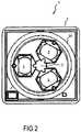
- FIG 2shows the lighting device 1 of FIG 1 in a top-down view.
- the transparent optics (and protection) layer 2gives view on the collimators 5 of the light source layer 3.
- the collimators 5, and thus the LEDs,are arranged in an angular three-fold symmetry around a centre point C and are - in this view - optically placed within the Fresnel structure.
- FIG 3shows the lighting device 1 of FIG 1 in a side view including exemplary dimensions.
- the Fresnel lensis 63 mm wide; while the optics layer 2 is slightly wider for reasons of subsequent assembly.
- the light source layer 3is 19.9 mm high, and the PCB 6 is 1.3 mm high.
- the heat sink 17 with its metal base plate 14 and heat dissipation pins 9is 15 mm high and spaced apart 12.60 mm from the fan 8 of height 15 mm and width 60 mm.
- FIG 4shows a layout of the printed circuit board 6 in a top-down view. Because the LEDs 4 are arranged on the heat sink parallel to the PCB 6, the PCB 6 shows cut-outs 10 for receiving the LEDs 4. Flexible extensions 11 from the PCB 6 reach into the cut-outs 10.
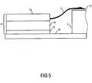
- FIG 5shows a cut-out side view of the lighting system in the vicinity of the flexible extensions 11.
- the printed circuit board 6has a multilayer structure with at least a flexible layer 12 that includes the flexible extensions 11 and an insulating layer 13 to insulate the upper layer (s) 12, 16 from a metal base plate 14 of a heat sink.
- the LEDs 4are also placed directly on the base plate for improved heat transfer.
- the extension 11 of the flexible layer 12is at least on its lower side covered by a copper film to contact the PCB 6 with the LEDs 4.
- the electrical contact between the flexible extension 11 and a respective LED 4are achieved by using a bonding pad 15 and a suitable connection technique, e. g., soldering.
- a suitable connection techniquee. g., soldering.
- the insulating layer 13may be made from the same material as the PCB laminates. This provides a sufficient electrical insulation between metal traces (wiring) at the bottom side of the wiring layer and the heat sink 14. In an alternative embodiment, the insulation layer may not be integrated in the printed circuit board.
- This arrangementprovides an easy to fabricate and reliable connection between the PCB 6 and other functional components 4. There are no other connection means needed. Because the shown design is susceptible to process automation of components and soldering, production and assembly costs can be reduced; this may be helped by the fact that multiple connections can made in the same step; i. e., that placing and soldering for all devices can be made at once. Also, for increased design flexibility, the PCB 6 can be placed on conductive surfaces thanks to its isolating bottom.
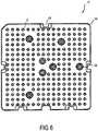
- FIG 6shows a heat sink 17 of the lighting device in a bottom-up view.
- a bedmade of the cylindrically shaped heat dissipation pins 9 in a substantially regular pattern. At some areas, pins are omitted to allow for through holes 18 to mount the heat sink 17, e.g. by screwing on.
- the base plate 14also comprises recesses 19 at its periphery with a minimum radius of the outer contour of 0,5 mm.
- the heat sink 17is made of at least 99 % pure aluminium, and has been fabricated by high pressure molding at a pressure above 800 bar to improve thermal conductivity.
- the effective coolingenables a high brightness thanks to an increased thermal efficiency.
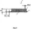
- FIG 7shows the heat sink of FIG 6 in a side view along the line A-A- of FIG 6 with respective dimensions in mm.
Landscapes
- Engineering & Computer Science (AREA)
- General Engineering & Computer Science (AREA)
- Microelectronics & Electronic Packaging (AREA)
- Physics & Mathematics (AREA)
- Optics & Photonics (AREA)
- Arrangement Of Elements, Cooling, Sealing, Or The Like Of Lighting Devices (AREA)
Description
- The invention relates to a lighting device, and in particular to a lighting device using high power sources, especially LEDs.
- Prior art lighting devices having high power LEDs use relatively bulky heat sinks to cool the LEDs which also makes the overall lighting devices bulky. Additionally, the relatively ineffective heat dissipation often affects the reliability of the system. Document
US 6,367,949 discloses a lighting device according to the preamble ofclaim 1. - It is thus the object of the present invention to provide a more compact and reliable lighting device, in particular for high power light sources like LEDs.
- The object is achieved by the lighting device according to
claim 1. Advantageous embodiments are especially defined by the dependent claims. - The lighting device comprises a stack of functional layers such that the device can be arranged in a compact manner. Because of the shorter connections and solid attachment, reliability is improved. The functional layers (or sections) comprise at least (not necessarily in this order):
- an optics layer comprising at least one optical element like a lens, a collimator etc., to shape light emitted from the light source layer;
- a light source layer comprising at least one light source, e.g., a LED or a laser diode, that is adapted to radiate light through the optics layer to an exterior;
- a printed circuit board comprising an electronic driver to drive / control the lighting device; and
- a cooling layer comprising at least one cooling element for cooling at least the light source(s).
- The stack structure adds flexibility and design effectiveness because the layers may be independently customized or adjusted according to the system needs. Also, an excellent integration level is achieved.
- Advantageously, the at least one light source comprises an LED array.
- Advantageously, a primary optics is attached to the at least one light source, e. g., a lens attached on or after a light emitting face of the respective light source.
- Advantageously, the optical element of the optics layer comprises a Fresnel structure common to the light sources.
- The printed circuit board comprises a flexible layer to connect to at least one of the other functional layers. The flexible layer advantageously at least connects the electronic driver to the at least one light source.
- The printed circuit board may advantageously comprise a lower / base insulation layer. In an alternative embodiment, the insulation layer may not be integrated with the printed circuit board.
- To maintain a cost effective and reliable electrical connection, at least portions of the flexible layers are metallised.
- To effectively cool at least the light source(s), the cooling layer comprises a metal heat sink and a fan for cooling the heat sink, i. e., an active heat sink. Advantageously, the heat sink comprises a bed of heat conduction / dissipation pins.
- Advantageously, the heat sink is made of more than 95 % pure aluminium, preferably at least 99 % pure aluminium, and is advantageously made by high pressure molding, especially at a pressure above 800 bar, to improve thermal conductivity. The effective cooling enables a high brightness thanks to an increased thermal efficiency.
- To effectively distribute heat away from the light sources, the at least one light source is directly attached to the heat sink.
- The lighting system will schematically be described in more detail in the following non-limiting and exemplary embodiment. Where applicable, the same reference numbers are used for identical or similar components.
- FIG 1
- shows a lighting device in a perspective view;
- FIG 2
- shows the lighting device of
FIG 1 in a top-down view; - FIG 3
- shows the lighting device of
FIG 1 in a side view; - FIG 4
- shows a layout of the printed circuit board in a top-down view;
- FIG 5
- shows a cut-out side view of the lighting system;
- FIG 6
- shows a heat sink of the lighting device in a bottom-up view; and
- FIG 7
- shows the heat sink of
FIG 6 in a side view. FIG 1 shows alighting device 1 without a housing for the sake of a better illustration. The lighting device comprises on top anoptics layer 2 comprising a Fresnel structure. Theoptics layer 2 also functions as a protective front cover.- Below the
optics layer 2 is arranged alight source layer 3 comprising threehigh power LEDs 4 that are covered by a primary optics including arespective collimator 5. Light emitted from theLEDs 4 is radiated through the respective primary optics /collimators 5 and then through the Fresnel structure of theoptics layer 2 to the exterior. The Fresnel structure is common to all three LEDs. It comprises several Fresnel rings (2A) and a pillow structure (not shown) inside therings 2A. - The
lighting device 1 further comprises a printedcircuit board 6 in turn comprising an electronic driver (not shown) to drive thelighting device 1, e. g., by controlling a LED current, or a fan speed (see below). - Further comprised is a
cooling layer 7 in turn comprising a heat sink 17 (seeFIG 6 ) and afan 8 for active cooling of theLEDs 4. Theheat sink 17 in turn comprises analuminium base plate 14 and a bed of heat-dissipatingpins 9 on its bottom side. Thefan 8 is shown spaced apart from theheat sink 17, as it is its position within the housing. Thefan 8 and theheat sink 17 are arranged one after the other / successively (superimposed). As it will be explained in more detail further below, thePCB 6 and theLEDs 4 are both directly mounted on the heat sink. - This superimposed stacked arrangement achieves a very compact and
reliable lighting device 1. FIG 2 shows thelighting device 1 ofFIG 1 in a top-down view. The transparent optics (and protection)layer 2 gives view on thecollimators 5 of thelight source layer 3. Thecollimators 5, and thus the LEDs, are arranged in an angular three-fold symmetry around a centre point C and are - in this view - optically placed within the Fresnel structure.FIG 3 shows thelighting device 1 ofFIG 1 in a side view including exemplary dimensions. The Fresnel lens is 63 mm wide; while theoptics layer 2 is slightly wider for reasons of subsequent assembly. Thelight source layer 3 is 19.9 mm high, and thePCB 6 is 1.3 mm high. Theheat sink 17 with itsmetal base plate 14 and heat dissipation pins 9 is 15 mm high and spaced apart 12.60 mm from thefan 8 ofheight 15 mm and width 60 mm.FIG 4 shows a layout of the printedcircuit board 6 in a top-down view. Because theLEDs 4 are arranged on the heat sink parallel to thePCB 6, thePCB 6 shows cut-outs 10 for receiving theLEDs 4.Flexible extensions 11 from thePCB 6 reach into the cut-outs 10.FIG 5 shows a cut-out side view of the lighting system in the vicinity of theflexible extensions 11. The printedcircuit board 6 has a multilayer structure with at least aflexible layer 12 that includes theflexible extensions 11 and an insulatinglayer 13 to insulate the upper layer (s) 12, 16 from ametal base plate 14 of a heat sink. TheLEDs 4 are also placed directly on the base plate for improved heat transfer.- The
extension 11 of theflexible layer 12 is at least on its lower side covered by a copper film to contact thePCB 6 with theLEDs 4. The electrical contact between theflexible extension 11 and arespective LED 4 are achieved by using abonding pad 15 and a suitable connection technique, e. g., soldering. Thus an electrical connection can be created between theLED 4, via thebonding pad 15 and theflexible extension 11 andflexible layer 12 to thewiring layer 16 which in turn is connected to electric and / or electronic components like an integrated driver circuit. - The insulating
layer 13 may be made from the same material as the PCB laminates. This provides a sufficient electrical insulation between metal traces (wiring) at the bottom side of the wiring layer and theheat sink 14.
In an alternative embodiment, the insulation layer may not be integrated in the printed circuit board. - This arrangement provides an easy to fabricate and reliable connection between the
PCB 6 and otherfunctional components 4. There are no other connection means needed. Because the shown design is susceptible to process automation of components and soldering, production and assembly costs can be reduced; this may be helped by the fact that multiple connections can made in the same step; i. e., that placing and soldering for all devices can be made at once. Also, for increased design flexibility, thePCB 6 can be placed on conductive surfaces thanks to its isolating bottom. FIG 6 shows aheat sink 17 of the lighting device in a bottom-up view. On thebase plate 14 of theheat sink 17 is provided a bed made of the cylindrically shapedheat dissipation pins 9 in a substantially regular pattern. At some areas, pins are omitted to allow for throughholes 18 to mount theheat sink 17, e.g. by screwing on. Thebase plate 14 also comprisesrecesses 19 at its periphery with a minimum radius of the outer contour of 0,5 mm.- The
heat sink 17 is made of at least 99 % pure aluminium, and has been fabricated by high pressure molding at a pressure above 800 bar to improve thermal conductivity. The effective cooling enables a high brightness thanks to an increased thermal efficiency. FIG 7 shows the heat sink ofFIG 6 in a side view along the line A-A- ofFIG 6 with respective dimensions in mm.- 1
- lighting device
- 2
- optics layer
- 2A
- Fresnel ring
- 3
- light source layer
- 4
- light source
- 5
- collimator
- 6
- printed circuit board
- 7
- cooling layer
- 8
- fan
- 9
- heat dissipation pin
- 10
- cut-out
- 11
- flexible extensions
- 12
- flexible layer
- 13
- insulating layer
- 14
- base plate
- 15
- bonding pad
- 16
- wiring layer
- 17
- heat sink
- 18
- through hole
- 19
- recess
- C
- centre point
Claims (17)
- A lighting device (1), comprising a stack of functional layers (2, 3, 6, 7), the functional layers comprising at least:- an optics layer (2) comprising at least one optical element;- a light source layer (3) comprising at least one light source (4) that is adapted to radiate light through the optics layer (2) to an exterior;- a printed circuit board (6) comprising an electronic driver to drive the lighting device (1); and- a cooling layer (7) comprising at least one cooling element (8, 17) for cooling at least the at least one light source (4),characterized in that- the printed circuit board (6) shows at least one cut-out (10) for receiving a respective light source (4),in that- the at least one light source (4) is arranged on the at least one cooling element (17) in parallel to the printed circuit board (6),in that- the printed circuit board (6) comprises a flexible layer (11,12) connecting to at least one of the other functional layers, andin that- the flexible layer (11,12) comprising flexible extensions (11) that reach into a respective cut-out (10).
- The lighting device (1) according to claim 1, wherein the flexible layer (11,12) electrically connects the electronic driver to the at least one light source (4).
- The lighting device (1) according to any of the preceding claims, wherein at least a portion (11) of the flexible layer (11, 12) is metallised.
- The lighting device (1) according to claim 3, wherein the at least one flexible extension (11) is covered by a copper film at least on its lower side to contact the printed circuit board (6) with the respective light source (4).
- The lighting device (1) according to claim 4, wherein an electrical contact between the flexible extension (11) and a respective light source (4) is achieved by using a bonding pad (15).
- The lighting device (1) according to any of the preceding claims, wherein the printed circuit board (6) comprises a multilayer structure, the multilayer structure comprising the flexible layer (11,12) and a lower insulation layer (13).
- The lighting device (1) according to claims 5 and 6, wherein the printed circuit board (6) comprises a wiring layer (16) creating an electrical connection between the at least one light source (4) and the electronic driver via the bonding pad (15), the flexible extension (11) and the flexible layer (12).
- The lighting device (1) according to claim 7, wherein the flexible layer (12) is placed atop the wiring layer (16).
- The lighting device (1) according to any of the preceding claims, wherein the at least one light source comprises an array of light emitting diodes (4).
- The lighting device (1) according to claim 10, wherein each light emitting diode (4) is attached to a respective primary optic (5).
- The lighting device (1) of any of the preceding claims, wherein the optical element is a Fresnel structure.
- The lighting device (1) of any of the preceding claims, wherein the cooling layer (7) comprises a heat sink (17) and a fan (8) for cooling the heat sink (17).
- The lighting device (1) of claim 12, wherein the heat sink (17) comprises an array of heat conduction pins (9).
- The lighting device (1) of claim 11 or 12, wherein the fan (8) is mounted successively to the heatsink (17).
- The lighting device (1) according to any of the claims 12 to 14, wherein the heat sink (17) is made of at least 99 % pure aluminium.
- The lighting device (1) of any of the claims 12 to 15, wherein the at least one light source (4) is directly attached to the heat sink (17).
- The lighting device (1) of any of the claims 12 to 13, wherein the printed circuit board (6) is directly mounted onto the heat sink (17).
Priority Applications (2)
| Application Number | Priority Date | Filing Date | Title |
|---|---|---|---|
| EP07010691.9AEP1998101B2 (en) | 2007-05-30 | 2007-05-30 | Lighting device |
| US12/129,058US8585247B2 (en) | 2007-05-30 | 2008-05-29 | Lighting device |
Applications Claiming Priority (1)
| Application Number | Priority Date | Filing Date | Title |
|---|---|---|---|
| EP07010691.9AEP1998101B2 (en) | 2007-05-30 | 2007-05-30 | Lighting device |
Publications (3)
| Publication Number | Publication Date |
|---|---|
| EP1998101A1 EP1998101A1 (en) | 2008-12-03 |
| EP1998101B1 EP1998101B1 (en) | 2016-04-27 |
| EP1998101B2true EP1998101B2 (en) | 2019-09-25 |
Family
ID=38610785
Family Applications (1)
| Application Number | Title | Priority Date | Filing Date |
|---|---|---|---|
| EP07010691.9AActiveEP1998101B2 (en) | 2007-05-30 | 2007-05-30 | Lighting device |
Country Status (2)
| Country | Link |
|---|---|
| US (1) | US8585247B2 (en) |
| EP (1) | EP1998101B2 (en) |
Families Citing this family (7)
| Publication number | Priority date | Publication date | Assignee | Title |
|---|---|---|---|---|
| WO2010082180A2 (en)* | 2009-01-16 | 2010-07-22 | Otto Horlacher | A lamp |
| CN102062363A (en)* | 2009-11-11 | 2011-05-18 | 富士迈半导体精密工业(上海)有限公司 | Lamp holder capable of being modularly spliced |
| US8297798B1 (en) | 2010-04-16 | 2012-10-30 | Cooper Technologies Company | LED lighting fixture |
| USD641918S1 (en) | 2010-04-16 | 2011-07-19 | Cooper Technologies Company | Lighting fixture |
| US9810419B1 (en) | 2010-12-03 | 2017-11-07 | Gary K. MART | LED light bulb |
| US8746915B2 (en)* | 2011-07-29 | 2014-06-10 | Cree, Inc. | Light emitting die (LED) lamps, heat sinks and related methods |
| JP5810900B2 (en)* | 2011-12-26 | 2015-11-11 | 市光工業株式会社 | Vehicle lighting |
Citations (4)
| Publication number | Priority date | Publication date | Assignee | Title |
|---|---|---|---|---|
| EP1139019A1 (en)† | 2000-03-31 | 2001-10-04 | Relume Corporation | L.E.D. thermal management |
| US20040222433A1 (en)† | 2003-05-05 | 2004-11-11 | Lamina Ceramics | Light emitting diodes packaged for high temperature operation |
| US20040264195A1 (en)† | 2003-06-25 | 2004-12-30 | Chia-Fu Chang | Led light source having a heat sink |
| US20060102914A1 (en)† | 2004-11-15 | 2006-05-18 | Lumileds Lighting U.S., Llc | Wide emitting lens for LED useful for backlighting |
Family Cites Families (22)
| Publication number | Priority date | Publication date | Assignee | Title |
|---|---|---|---|---|
| EP1056971A1 (en)* | 1998-12-17 | 2000-12-06 | Koninklijke Philips Electronics N.V. | Light engine |
| US6502968B1 (en)* | 1998-12-22 | 2003-01-07 | Mannesmann Vdo Ag | Printed circuit board having a light source |
| US6367949B1 (en)* | 1999-08-04 | 2002-04-09 | 911 Emergency Products, Inc. | Par 36 LED utility lamp |
| US6582100B1 (en)* | 2000-08-09 | 2003-06-24 | Relume Corporation | LED mounting system |
| EP1451872B1 (en)* | 2001-09-13 | 2007-03-07 | Lucea AG | Light emitting diode-based luminous panel and carrier plate |
| US7273987B2 (en)* | 2002-03-21 | 2007-09-25 | General Electric Company | Flexible interconnect structures for electrical devices and light sources incorporating the same |
| US6864513B2 (en)* | 2003-05-07 | 2005-03-08 | Kaylu Industrial Corporation | Light emitting diode bulb having high heat dissipating efficiency |
| US6999318B2 (en)* | 2003-07-28 | 2006-02-14 | Honeywell International Inc. | Heatsinking electronic devices |
| US20050116235A1 (en)* | 2003-12-02 | 2005-06-02 | Schultz John C. | Illumination assembly |
| US7128438B2 (en)* | 2004-02-05 | 2006-10-31 | Agilight, Inc. | Light display structures |
| US20060044806A1 (en)* | 2004-08-25 | 2006-03-02 | Abramov Vladimir S | Light emitting diode system packages |
| US7303315B2 (en) | 2004-11-05 | 2007-12-04 | 3M Innovative Properties Company | Illumination assembly using circuitized strips |
| TWI255377B (en)* | 2004-11-05 | 2006-05-21 | Au Optronics Corp | Backlight module |
| US7284882B2 (en)* | 2005-02-17 | 2007-10-23 | Federal-Mogul World Wide, Inc. | LED light module assembly |
| US7703951B2 (en)* | 2005-05-23 | 2010-04-27 | Philips Solid-State Lighting Solutions, Inc. | Modular LED-based lighting fixtures having socket engagement features |
| TWI256454B (en)* | 2005-06-03 | 2006-06-11 | Au Optronics Corp | Light module |
| TWI333576B (en)* | 2005-08-17 | 2010-11-21 | Au Optronics Corp | Bottom lighting module |
| US7676915B2 (en)* | 2005-09-22 | 2010-03-16 | The Artak Ter-Hovhanissian Patent Trust | Process for manufacturing an LED lamp with integrated heat sink |
| US7705365B2 (en)* | 2006-01-24 | 2010-04-27 | Denso Corporation | Lighting device and light emitting module for the same |
| TWI290777B (en)* | 2006-02-27 | 2007-12-01 | Guei-Fang Chen | Lighting device with light emitting diode |
| DE102006048230B4 (en)* | 2006-10-11 | 2012-11-08 | Osram Ag | Light-emitting diode system, method for producing such and backlighting device |
| US9086213B2 (en)* | 2007-10-17 | 2015-07-21 | Xicato, Inc. | Illumination device with light emitting diodes |
- 2007
- 2007-05-30EPEP07010691.9Apatent/EP1998101B2/enactiveActive
- 2008
- 2008-05-29USUS12/129,058patent/US8585247B2/enactiveActive
Patent Citations (4)
| Publication number | Priority date | Publication date | Assignee | Title |
|---|---|---|---|---|
| EP1139019A1 (en)† | 2000-03-31 | 2001-10-04 | Relume Corporation | L.E.D. thermal management |
| US20040222433A1 (en)† | 2003-05-05 | 2004-11-11 | Lamina Ceramics | Light emitting diodes packaged for high temperature operation |
| US20040264195A1 (en)† | 2003-06-25 | 2004-12-30 | Chia-Fu Chang | Led light source having a heat sink |
| US20060102914A1 (en)† | 2004-11-15 | 2006-05-18 | Lumileds Lighting U.S., Llc | Wide emitting lens for LED useful for backlighting |
Also Published As
| Publication number | Publication date |
|---|---|
| US8585247B2 (en) | 2013-11-19 |
| EP1998101B1 (en) | 2016-04-27 |
| US20090009996A1 (en) | 2009-01-08 |
| EP1998101A1 (en) | 2008-12-03 |
Similar Documents
| Publication | Publication Date | Title |
|---|---|---|
| US20110180819A1 (en) | Light-emitting arrangement | |
| EP3602626B1 (en) | Lighting device with led elements on a mounting element on a flat carrier and method of manufacturing the same | |
| US7771082B2 (en) | Lamp with heat conducting structure and lamp cover thereof | |
| KR101934075B1 (en) | Film system for led applications | |
| US8253026B2 (en) | Printed circuit board | |
| US7482632B2 (en) | LED assembly and use thereof | |
| EP1998101B2 (en) | Lighting device | |
| JP4969332B2 (en) | Substrate and lighting device | |
| US10236429B2 (en) | Mounting assembly and lighting device | |
| CN101180498A (en) | Led light module assembly | |
| EP3133332B1 (en) | Integrated led module with ims substrate | |
| GB2480428A (en) | PCB with metal core having extended heatsink bosses for mounting LEDs | |
| EP3259526B1 (en) | Led lighting unit | |
| KR101963738B1 (en) | Led lighting apparatus | |
| JP5968647B2 (en) | LED lamp and LED lighting device | |
| WO2018001363A1 (en) | Led circuit board, led module and lighting fixture | |
| CN101118035B (en) | Lighting components and their use | |
| EP2788971A1 (en) | Led luminaire | |
| JP6772828B2 (en) | lighting equipment | |
| JP2010102924A (en) | Illuminating device | |
| HK1100298B (en) | Cooling device for light emitting element | |
| KR20120068642A (en) | Printed circuit board and lighting device having the same |
Legal Events
| Date | Code | Title | Description |
|---|---|---|---|
| PUAI | Public reference made under article 153(3) epc to a published international application that has entered the european phase | Free format text:ORIGINAL CODE: 0009012 | |
| AK | Designated contracting states | Kind code of ref document:A1 Designated state(s):AT BE BG CH CY CZ DE DK EE ES FI FR GB GR HU IE IS IT LI LT LU LV MC MT NL PL PT RO SE SI SK TR | |
| AX | Request for extension of the european patent | Extension state:AL BA HR MK RS | |
| 17P | Request for examination filed | Effective date:20090218 | |
| AKX | Designation fees paid | Designated state(s):AT BE BG CH CY CZ DE DK EE ES FI FR GB GR HU IE IS IT LI LT LU LV MC MT NL PL PT RO SE SI SK TR | |
| 17Q | First examination report despatched | Effective date:20110321 | |
| RAP1 | Party data changed (applicant data changed or rights of an application transferred) | Owner name:OSRAM AG Owner name:OSRAM S.P.A. - SOCIETA' RIUNITE OSRAM EDISON CLERI | |
| RAP1 | Party data changed (applicant data changed or rights of an application transferred) | Owner name:OSRAM GMBH Owner name:OSRAM S.P.A. - SOCIETA' RIUNITE OSRAM EDISON CLERI | |
| RAP1 | Party data changed (applicant data changed or rights of an application transferred) | Owner name:OSRAM GMBH Owner name:OSRAM S.P.A. - SOCIETA' RIUNITE OSRAM EDISON CLERI | |
| RAP1 | Party data changed (applicant data changed or rights of an application transferred) | Owner name:OSRAM GMBH Owner name:OSRAM S.P.A. - SOCIETA' RIUNITE OSRAM EDISON CLERI | |
| GRAP | Despatch of communication of intention to grant a patent | Free format text:ORIGINAL CODE: EPIDOSNIGR1 | |
| RIC1 | Information provided on ipc code assigned before grant | Ipc:F21Y 101/02 00000000ALN20151127BHEP Ipc:F21K 99/00 20160101AFI20151127BHEP | |
| INTG | Intention to grant announced | Effective date:20151216 | |
| GRAS | Grant fee paid | Free format text:ORIGINAL CODE: EPIDOSNIGR3 | |
| REG | Reference to a national code | Ref country code:DE Ref legal event code:R079 Ref document number:602007045993 Country of ref document:DE Free format text:PREVIOUS MAIN CLASS: F21K0007000000 Ipc:F21K0009000000 | |
| GRAA | (expected) grant | Free format text:ORIGINAL CODE: 0009210 | |
| RIC1 | Information provided on ipc code assigned before grant | Ipc:F21Y 115/10 20160101ALN20160311BHEP Ipc:F21K 9/00 20160101AFI20160311BHEP | |
| AK | Designated contracting states | Kind code of ref document:B1 Designated state(s):AT BE BG CH CY CZ DE DK EE ES FI FR GB GR HU IE IS IT LI LT LU LV MC MT NL PL PT RO SE SI SK TR | |
| REG | Reference to a national code | Ref country code:GB Ref legal event code:FG4D | |
| REG | Reference to a national code | Ref country code:CH Ref legal event code:NV Representative=s name:BOVARD AG, CH Ref country code:CH Ref legal event code:EP | |
| REG | Reference to a national code | Ref country code:AT Ref legal event code:REF Ref document number:795218 Country of ref document:AT Kind code of ref document:T Effective date:20160515 | |
| REG | Reference to a national code | Ref country code:IE Ref legal event code:FG4D | |
| REG | Reference to a national code | Ref country code:FR Ref legal event code:PLFP Year of fee payment:10 | |
| REG | Reference to a national code | Ref country code:DE Ref legal event code:R096 Ref document number:602007045993 Country of ref document:DE | |
| REG | Reference to a national code | Ref country code:LT Ref legal event code:MG4D | |
| PG25 | Lapsed in a contracting state [announced via postgrant information from national office to epo] | Ref country code:BE Free format text:LAPSE BECAUSE OF NON-PAYMENT OF DUE FEES Effective date:20160531 | |
| REG | Reference to a national code | Ref country code:NL Ref legal event code:MP Effective date:20160427 | |
| PG25 | Lapsed in a contracting state [announced via postgrant information from national office to epo] | Ref country code:NL Free format text:LAPSE BECAUSE OF FAILURE TO SUBMIT A TRANSLATION OF THE DESCRIPTION OR TO PAY THE FEE WITHIN THE PRESCRIBED TIME-LIMIT Effective date:20160427 | |
| PG25 | Lapsed in a contracting state [announced via postgrant information from national office to epo] | Ref country code:FI Free format text:LAPSE BECAUSE OF FAILURE TO SUBMIT A TRANSLATION OF THE DESCRIPTION OR TO PAY THE FEE WITHIN THE PRESCRIBED TIME-LIMIT Effective date:20160427 Ref country code:PL Free format text:LAPSE BECAUSE OF FAILURE TO SUBMIT A TRANSLATION OF THE DESCRIPTION OR TO PAY THE FEE WITHIN THE PRESCRIBED TIME-LIMIT Effective date:20160427 Ref country code:LT Free format text:LAPSE BECAUSE OF FAILURE TO SUBMIT A TRANSLATION OF THE DESCRIPTION OR TO PAY THE FEE WITHIN THE PRESCRIBED TIME-LIMIT Effective date:20160427 | |
| PG25 | Lapsed in a contracting state [announced via postgrant information from national office to epo] | Ref country code:SE Free format text:LAPSE BECAUSE OF FAILURE TO SUBMIT A TRANSLATION OF THE DESCRIPTION OR TO PAY THE FEE WITHIN THE PRESCRIBED TIME-LIMIT Effective date:20160427 Ref country code:ES Free format text:LAPSE BECAUSE OF FAILURE TO SUBMIT A TRANSLATION OF THE DESCRIPTION OR TO PAY THE FEE WITHIN THE PRESCRIBED TIME-LIMIT Effective date:20160427 Ref country code:LV Free format text:LAPSE BECAUSE OF FAILURE TO SUBMIT A TRANSLATION OF THE DESCRIPTION OR TO PAY THE FEE WITHIN THE PRESCRIBED TIME-LIMIT Effective date:20160427 Ref country code:PT Free format text:LAPSE BECAUSE OF FAILURE TO SUBMIT A TRANSLATION OF THE DESCRIPTION OR TO PAY THE FEE WITHIN THE PRESCRIBED TIME-LIMIT Effective date:20160829 Ref country code:GR Free format text:LAPSE BECAUSE OF FAILURE TO SUBMIT A TRANSLATION OF THE DESCRIPTION OR TO PAY THE FEE WITHIN THE PRESCRIBED TIME-LIMIT Effective date:20160728 | |
| PG25 | Lapsed in a contracting state [announced via postgrant information from national office to epo] | Ref country code:BE Free format text:LAPSE BECAUSE OF FAILURE TO SUBMIT A TRANSLATION OF THE DESCRIPTION OR TO PAY THE FEE WITHIN THE PRESCRIBED TIME-LIMIT Effective date:20160427 | |
| REG | Reference to a national code | Ref country code:DE Ref legal event code:R026 Ref document number:602007045993 Country of ref document:DE | |
| PG25 | Lapsed in a contracting state [announced via postgrant information from national office to epo] | Ref country code:RO Free format text:LAPSE BECAUSE OF FAILURE TO SUBMIT A TRANSLATION OF THE DESCRIPTION OR TO PAY THE FEE WITHIN THE PRESCRIBED TIME-LIMIT Effective date:20160427 Ref country code:SK Free format text:LAPSE BECAUSE OF FAILURE TO SUBMIT A TRANSLATION OF THE DESCRIPTION OR TO PAY THE FEE WITHIN THE PRESCRIBED TIME-LIMIT Effective date:20160427 Ref country code:DK Free format text:LAPSE BECAUSE OF FAILURE TO SUBMIT A TRANSLATION OF THE DESCRIPTION OR TO PAY THE FEE WITHIN THE PRESCRIBED TIME-LIMIT Effective date:20160427 Ref country code:MC Free format text:LAPSE BECAUSE OF FAILURE TO SUBMIT A TRANSLATION OF THE DESCRIPTION OR TO PAY THE FEE WITHIN THE PRESCRIBED TIME-LIMIT Effective date:20160427 Ref country code:EE Free format text:LAPSE BECAUSE OF FAILURE TO SUBMIT A TRANSLATION OF THE DESCRIPTION OR TO PAY THE FEE WITHIN THE PRESCRIBED TIME-LIMIT Effective date:20160427 Ref country code:CZ Free format text:LAPSE BECAUSE OF FAILURE TO SUBMIT A TRANSLATION OF THE DESCRIPTION OR TO PAY THE FEE WITHIN THE PRESCRIBED TIME-LIMIT Effective date:20160427 | |
| PLBI | Opposition filed | Free format text:ORIGINAL CODE: 0009260 | |
| REG | Reference to a national code | Ref country code:IE Ref legal event code:MM4A | |
| PLAX | Notice of opposition and request to file observation + time limit sent | Free format text:ORIGINAL CODE: EPIDOSNOBS2 | |
| 26 | Opposition filed | Opponent name:VALEO VISION SAS Effective date:20170127 | |
| GBPC | Gb: european patent ceased through non-payment of renewal fee | Effective date:20160727 | |
| REG | Reference to a national code | Ref country code:FR Ref legal event code:PLFP Year of fee payment:11 | |
| PG25 | Lapsed in a contracting state [announced via postgrant information from national office to epo] | Ref country code:GB Free format text:LAPSE BECAUSE OF NON-PAYMENT OF DUE FEES Effective date:20160727 Ref country code:IE Free format text:LAPSE BECAUSE OF NON-PAYMENT OF DUE FEES Effective date:20160530 Ref country code:SI Free format text:LAPSE BECAUSE OF FAILURE TO SUBMIT A TRANSLATION OF THE DESCRIPTION OR TO PAY THE FEE WITHIN THE PRESCRIBED TIME-LIMIT Effective date:20160427 | |
| PLBB | Reply of patent proprietor to notice(s) of opposition received | Free format text:ORIGINAL CODE: EPIDOSNOBS3 | |
| REG | Reference to a national code | Ref country code:FR Ref legal event code:PLFP Year of fee payment:12 | |
| PG25 | Lapsed in a contracting state [announced via postgrant information from national office to epo] | Ref country code:HU Free format text:LAPSE BECAUSE OF FAILURE TO SUBMIT A TRANSLATION OF THE DESCRIPTION OR TO PAY THE FEE WITHIN THE PRESCRIBED TIME-LIMIT; INVALID AB INITIO Effective date:20070530 Ref country code:CY Free format text:LAPSE BECAUSE OF FAILURE TO SUBMIT A TRANSLATION OF THE DESCRIPTION OR TO PAY THE FEE WITHIN THE PRESCRIBED TIME-LIMIT Effective date:20160427 | |
| PG25 | Lapsed in a contracting state [announced via postgrant information from national office to epo] | Ref country code:IS Free format text:LAPSE BECAUSE OF FAILURE TO SUBMIT A TRANSLATION OF THE DESCRIPTION OR TO PAY THE FEE WITHIN THE PRESCRIBED TIME-LIMIT Effective date:20160427 Ref country code:TR Free format text:LAPSE BECAUSE OF FAILURE TO SUBMIT A TRANSLATION OF THE DESCRIPTION OR TO PAY THE FEE WITHIN THE PRESCRIBED TIME-LIMIT Effective date:20160427 Ref country code:MT Free format text:LAPSE BECAUSE OF NON-PAYMENT OF DUE FEES Effective date:20160531 Ref country code:LU Free format text:LAPSE BECAUSE OF NON-PAYMENT OF DUE FEES Effective date:20160530 | |
| PG25 | Lapsed in a contracting state [announced via postgrant information from national office to epo] | Ref country code:BG Free format text:LAPSE BECAUSE OF FAILURE TO SUBMIT A TRANSLATION OF THE DESCRIPTION OR TO PAY THE FEE WITHIN THE PRESCRIBED TIME-LIMIT Effective date:20160427 | |
| REG | Reference to a national code | Ref country code:AT Ref legal event code:UEP Ref document number:795218 Country of ref document:AT Kind code of ref document:T Effective date:20160427 | |
| REG | Reference to a national code | Ref country code:CH Ref legal event code:PK Free format text:BERICHTIGUNGEN | |
| RIC2 | Information provided on ipc code assigned after grant | Ipc:H05K 1/02 20060101ALN20190415BHEP Ipc:F21K 9/00 20160101AFI20190415BHEP Ipc:F21Y 115/10 20160101ALN20190415BHEP | |
| PUAH | Patent maintained in amended form | Free format text:ORIGINAL CODE: 0009272 | |
| STAA | Information on the status of an ep patent application or granted ep patent | Free format text:STATUS: PATENT MAINTAINED AS AMENDED | |
| REG | Reference to a national code | Ref country code:CH Ref legal event code:AELC | |
| 27A | Patent maintained in amended form | Effective date:20190925 | |
| AK | Designated contracting states | Kind code of ref document:B2 Designated state(s):AT BE BG CH CY CZ DE DK EE ES FI FR GB GR HU IE IS IT LI LT LU LV MC MT NL PL PT RO SE SI SK TR | |
| REG | Reference to a national code | Ref country code:DE Ref legal event code:R102 Ref document number:602007045993 Country of ref document:DE | |
| PGFP | Annual fee paid to national office [announced via postgrant information from national office to epo] | Ref country code:AT Payment date:20190522 Year of fee payment:13 | |
| REG | Reference to a national code | Ref country code:AT Ref legal event code:MK05 Ref document number:795218 Country of ref document:AT Kind code of ref document:T Effective date:20160427 | |
| PG25 | Lapsed in a contracting state [announced via postgrant information from national office to epo] | Ref country code:AT Free format text:LAPSE BECAUSE OF FAILURE TO SUBMIT A TRANSLATION OF THE DESCRIPTION OR TO PAY THE FEE WITHIN THE PRESCRIBED TIME-LIMIT Effective date:20160427 | |
| PGFP | Annual fee paid to national office [announced via postgrant information from national office to epo] | Ref country code:CH Payment date:20200520 Year of fee payment:14 Ref country code:FR Payment date:20200522 Year of fee payment:14 | |
| PGFP | Annual fee paid to national office [announced via postgrant information from national office to epo] | Ref country code:IT Payment date:20200528 Year of fee payment:14 | |
| REG | Reference to a national code | Ref country code:CH Ref legal event code:PL | |
| PG25 | Lapsed in a contracting state [announced via postgrant information from national office to epo] | Ref country code:LI Free format text:LAPSE BECAUSE OF NON-PAYMENT OF DUE FEES Effective date:20210531 Ref country code:CH Free format text:LAPSE BECAUSE OF NON-PAYMENT OF DUE FEES Effective date:20210531 | |
| PG25 | Lapsed in a contracting state [announced via postgrant information from national office to epo] | Ref country code:FR Free format text:LAPSE BECAUSE OF NON-PAYMENT OF DUE FEES Effective date:20210531 | |
| PG25 | Lapsed in a contracting state [announced via postgrant information from national office to epo] | Ref country code:IT Free format text:LAPSE BECAUSE OF NON-PAYMENT OF DUE FEES Effective date:20200530 | |
| P01 | Opt-out of the competence of the unified patent court (upc) registered | Effective date:20230821 | |
| PGFP | Annual fee paid to national office [announced via postgrant information from national office to epo] | Ref country code:DE Payment date:20240521 Year of fee payment:18 | |
| PG25 | Lapsed in a contracting state [announced via postgrant information from national office to epo] | Ref country code:IT Free format text:LAPSE BECAUSE OF NON-PAYMENT OF DUE FEES Effective date:20210530 |