EP1997444B1 - Access assembly with whisker seal - Google Patents
Access assembly with whisker sealDownload PDFInfo
- Publication number
- EP1997444B1 EP1997444B1EP08251759AEP08251759AEP1997444B1EP 1997444 B1EP1997444 B1EP 1997444B1EP 08251759 AEP08251759 AEP 08251759AEP 08251759 AEP08251759 AEP 08251759AEP 1997444 B1EP1997444 B1EP 1997444B1
- Authority
- EP
- European Patent Office
- Prior art keywords
- bristle members
- seal
- bristle
- seal member
- longitudinal axis
- Prior art date
- Legal status (The legal status is an assumption and is not a legal conclusion. Google has not performed a legal analysis and makes no representation as to the accuracy of the status listed.)
- Not-in-force
Links
- 239000000758substrateSubstances0.000claimsdescription33
- 238000003780insertionMethods0.000claimsdescription7
- 230000037431insertionEffects0.000claimsdescription7
- 230000007246mechanismEffects0.000description5
- 238000000034methodMethods0.000description5
- 230000000149penetrating effectEffects0.000description5
- 238000007789sealingMethods0.000description5
- 238000001356surgical procedureMethods0.000description5
- 238000005452bendingMethods0.000description4
- 210000001519tissueAnatomy0.000description4
- 239000012530fluidSubstances0.000description3
- 239000007789gasSubstances0.000description3
- 239000003381stabilizerSubstances0.000description3
- 241001631457CannulaSpecies0.000description2
- 210000000683abdominal cavityAnatomy0.000description2
- 230000003247decreasing effectEffects0.000description2
- 239000013536elastomeric materialSubstances0.000description2
- 230000002093peripheral effectEffects0.000description2
- 239000007787solidSubstances0.000description2
- 241000282326Felis catusSpecies0.000description1
- 244000043261Hevea brasiliensisSpecies0.000description1
- 241000405070PercophidaeSpecies0.000description1
- 239000000853adhesiveSubstances0.000description1
- 230000001070adhesive effectEffects0.000description1
- 230000000712assemblyEffects0.000description1
- 238000000429assemblyMethods0.000description1
- 239000000560biocompatible materialSubstances0.000description1
- 238000002788crimpingMethods0.000description1
- 230000001419dependent effectEffects0.000description1
- 238000006073displacement reactionMethods0.000description1
- 239000000835fiberSubstances0.000description1
- 239000000463materialSubstances0.000description1
- 229910052751metalInorganic materials0.000description1
- 239000002184metalSubstances0.000description1
- 150000002739metalsChemical class0.000description1
- 238000002324minimally invasive surgeryMethods0.000description1
- 238000012986modificationMethods0.000description1
- 230000004048modificationEffects0.000description1
- 229920003052natural elastomerPolymers0.000description1
- 229920001194natural rubberPolymers0.000description1
- 230000035515penetrationEffects0.000description1
- 210000003200peritoneal cavityAnatomy0.000description1
- 229920000642polymerPolymers0.000description1
- 239000012858resilient materialSubstances0.000description1
- 230000000087stabilizing effectEffects0.000description1
- 229920003051synthetic elastomerPolymers0.000description1
- 210000001835visceraAnatomy0.000description1
Images


Classifications
- A—HUMAN NECESSITIES
- A61—MEDICAL OR VETERINARY SCIENCE; HYGIENE
- A61B—DIAGNOSIS; SURGERY; IDENTIFICATION
- A61B17/00—Surgical instruments, devices or methods
- A61B17/34—Trocars; Puncturing needles
- A61B17/3462—Trocars; Puncturing needles with means for changing the diameter or the orientation of the entrance port of the cannula, e.g. for use with different-sized instruments, reduction ports, adapter seals
- F—MECHANICAL ENGINEERING; LIGHTING; HEATING; WEAPONS; BLASTING
- F16—ENGINEERING ELEMENTS AND UNITS; GENERAL MEASURES FOR PRODUCING AND MAINTAINING EFFECTIVE FUNCTIONING OF MACHINES OR INSTALLATIONS; THERMAL INSULATION IN GENERAL
- F16J—PISTONS; CYLINDERS; SEALINGS
- F16J15/00—Sealings
- F16J15/16—Sealings between relatively-moving surfaces
- F16J15/32—Sealings between relatively-moving surfaces with elastic sealings, e.g. O-rings
- F16J15/3284—Sealings between relatively-moving surfaces with elastic sealings, e.g. O-rings characterised by their structure; Selection of materials
- F16J15/3288—Filamentary structures, e.g. brush seals
- A—HUMAN NECESSITIES
- A61—MEDICAL OR VETERINARY SCIENCE; HYGIENE
- A61B—DIAGNOSIS; SURGERY; IDENTIFICATION
- A61B17/00—Surgical instruments, devices or methods
- A61B17/34—Trocars; Puncturing needles
- A61B17/3498—Valves therefor, e.g. flapper valves, slide valves
- A—HUMAN NECESSITIES
- A61—MEDICAL OR VETERINARY SCIENCE; HYGIENE
- A61B—DIAGNOSIS; SURGERY; IDENTIFICATION
- A61B17/00—Surgical instruments, devices or methods
- A61B17/32—Surgical cutting instruments
- A61B2017/320004—Surgical cutting instruments abrasive
- A61B2017/320012—Brushes
Definitions
- the present disclosurerelates to an access apparatus for providing access to an underlying surgical site, and, more particularly, relates to an access apparatus incorporating a novel seal mechanism adapted to permit ease of insertion of a surgical instrument while providing a substantial seal about the instrument upon manipulation during the surgical procedure.
- Surgical access apparatiiare employed in various minimally invasive procedures including laparoscopic or endoscopic procedures. Such access apparatii are inclusive of portals, trocar cannulas, catheters, or, in the event of a minimally invasive hand assist procedures, hand access devices.
- Surgical access apparatiitypically incorporate a seal mechanism to form a fluid tight seal about an instrument or hand passed through the portal.
- the seal mechanismsoften are limited, in part, due to the large insertion forces required to pass the object through the seal of the seal mechanism.
- off-axis movement of the instrument within the sealmay be too difficult or easy depending on the type of seal employed within the portal.
- the seal mechanismsare also limited by their ability to sustain their integrity when the surgical instrument is angulated.
- the present disclosureis directed to a surgical access assembly for sealed reception of an elongated object as claimed in claim 1.
- the surgical access assemblyincludes an access member having at least one opening configured and dimensioned to permit entry of an elongated object and being adapted for positioning within tissue to provide access to an underlying surgical site.
- a seal memberis mounted relative to the access member.
- the seal memberincludes an outer substrate and a plurality of flexible bristle members extending radially inwardly from the outer substrate to the central longitudinal axis.
- the bristle membersdefine free ends remote from the outer substrate and being adapted to flex and form a substantial seal about the elongated object.
- the fixe ends of the bristle membershave an axial component of direction w.r.t.
- the bristle memberscan be dimensioned to define a thickness or density which is greater at the free ends thereof relative to remaining portions of the bristle members.
- proximalas is traditional, will refer to the end of the apparatus which is closest to the clinician, while the term “distal” will refer to the end which is furthest from the clinician.
- instrument(s)contemplates the introduction into a body cavity of all types of surgical instruments including clip appliers, graspers, dissectors, retractors, staplers, laser fibers, photographic devices, endoscopes and laparoscopss, tubes, and the like. All such objects are referred to herein as "instrument(s)”.
- FIG. 1a surgical system in accordance with the present disclosure.
- System 10has particular application in laparoscopic procedures with respect to accessing the abdominal cavity, and the like, and may be used in any such surgical procedure where the peritoneal cavity is insufflated with a suitable gas, e.g., CO 2 , to separate the cavity wall from the internal organs housed therein.
- System 10includes cannula assembly 100 and obturator assembly 200, which is positionable therein.
- Obturator assembly 200includes obturator 202, which includes obturator housing 204 and sleeve or outer member 206 extending therefrom.
- Obturator housing 204is advantageously dimensioned for grasping by a clinician.
- Obturator 202further includes penetrating member 208 within sleeve 206. Penetrating member 208 punctures the abdominal cavity or the like, thereby creating an access point through which at least a portion of a surgical procedure may be conducted.
- Sleeve 206may be adapted to retract upon insertion into tissue to expose penetrating member 208 to permit the penetrating member 208 to incise the tissue. Alternatively, penetrating member 208 may be adapted to advance within sleeve 206. Following penetration, obturator assembly 200 is removed from cannula assembly 100 to permit the subsequent introduction of surgical instrumentation utilized to carry out the remainder of the procedure through cannula assembly 100.
- cannula assembly 100includes cannula housing 102 and cannula member 104 having an outer wall 106 and defining longitudinal axis "A".
- Cannula member 104defines an internal longitudinal lumen 108 within outer wall 106 dimensioned to permit the passage of surgical instrumentation therethrough.
- Either or both of cannula housing 102 and cannula member 104may be opaque or transparent, either wholly or in part, and may be fabricated from any biocompatible material including metals or polymers.
- Cannula housing 102also incorporates cannula valve 110, and stabilizing plate 112 which secures the cannula valve 110 to cannula housing 102.
- Cannula valve 110is a zero closure valve adapted to assume a substantially closed position in the absence of an instrument to prevent passage of gases therethrough.
- cannula valve 110is a duckbill or trumpet valve.
- Cannula housing 102further includes stop cock valve 114 which is connectable to a source of insufflation fluids to distribute the fluids to the underlying body cavity.
- instrument seal assembly 300 of the present disclosureis adapted to provide a substantial seal between a body cavity of a patient and the atmosphere outside the patient while an instrument is inserted through the cannula assembly 100.
- Seal assembly 300may be formed integrally with cannula assembly 200, or may preferably be detachably mounted to cannula assembly 200. Additionally, seal assembly 300 may be readily adapted to be mounted to conventional cannulas of differing structures. Among other advantages, the detachability of seal assembly 300 facilitates the removal of irregularly shaped body tissue and reduces the profile of the cannula whenever the seal assembly is unnecessary for a portion of the surgical procedure.
- Seal assembly 300includes end cap 302, stabilizer plate 304, seal member 306 and seal housing 308.
- End cap 302, stabilizer plate 304 and seal housing 308form the outer seal body of seal assembly 100, which houses the sealing component, i.e., seal member 306.
- End cap 302is generally cylindrically-shaped and includes proximal end portion 310 defining a diameter which is less than the diameter of the remaining portion of the end cap 302, and an inner peripheral ledge 312 which supports stabilizer plate 304.
- Seal housing 308includes central opening 314, inner cylindrical portion 316 and distal outer flange 318 having a scalloped surface to facilitate handling thereof. Cylindrical portion 316 is received within end cap 302 when the seal assembly 300 is fully assembled to enclose the sealing components.
- Seal housing 308includes peripheral groove 320 and two opposed ribs 322 extending radially inwardly adjacent the groove 320. Groove 320 and ribs 322 assist in mounting seal assembly 300 to cannula assembly 200 as will be appreciated from the description provided below. Seal housing 308 also includes second groove 324 adjacent opening 314 for accommodating seal member 306.
- seal member 306includes substrate 326 and a plurality of bristle members 328 attached to the substrate 326 and extending therefrom. Bristle members 328 define aperture 330, which as will be described in greater detail below, need not be dimensioned uniformly through the seal member 306.
- substrate 326may be formed as a u-shaped channel such that a plurality of perpendicularly projecting bristle members 328 may be clamped therein by crimping the ends of the u-shaped channel.
- substrate 326may be a strip of adhesive material, an overmolded element molded onto one end of bristle members 328 or the like.
- Each bristle member 328thus will have a secured end 332 adjacent to substrate 326 and a free end 334 opposite the secured end 332.
- Other similar methodsmay be used to provide a generally flat substrate with bristle members 328 projecting perpendicularly from a single face of the substrate. This arrangement defines a flat brush profile wherein all bristle members are generally the same length.
- a generally flat surfaceis formed by the free ends 334 of the bristle members 328 being generally parallel to substrate 326.
- Bristle members 328are preferably fabricated from an elastomeric material such as synthetic or natural rubber which is preferably sufficiently resilient to accommodate and provide a substantial seal with instruments of varying diameters.
- the geometry of bristle members 328is preferably long and slender.
- Flat substrate 326is curved to form a generally round ring structure to provide seal member 306 generally as seen in FIG. 3B .
- bristle member 328are directed radially inwardly to define aperture 330 with free ends 334 of the bristle members 328 in close proximity with each other as compared to secured ends 332 of the bristle members 328 which substantially maintain their spacing near the substrate 326.
- This congregation of free ends 334 of bristle member 328can result in a higher bristle density at the center of the ring near aperture 330 than at the outer regions near substrate 326.
- bristle member 328If the number and geometry of bristle member 328 is sufficient, a saturation point may be reached where free ends 334 of the bristle member 328 require more space than is available within the confines of the cylinder defined by the substrate 326 thereby resulting in opposed bulges 336 formed near the center of the ring as can be seen in the alternate embodiment of FIG. 4 whereby free ends 334 have an axial component of direction corresponding to the invention as claimed.
- Seal member 306 arranged in this mannercan provide robust lateral support for relatively small instruments having outer dimensions approximating the diameter of aperture 330.
- a tapered brush profileas shown in FIG. 5 , can produce a seal member having a lower required insertion force for larger instruments. This is because fewer bristles will need to compete for the limited space near the aperture 330, and fewer bristles will need to bend to accommodate the instrument.
- This arrangementis characterized by a brush profile which is uniform along the length of the substrate 326 with a decreasing bristle cross-sectional dimension in the direction of the free ends of the bristles.
- any bulge created in the case of the straight brush profilemay be reduced or eliminated resulting in a relatively thin seal member.
- a saw-tooth brush profile as shown in FIG. 6may be provided.
- the saw-tooth profileis characterized by bristle members 328 arranged in groups or sets 350 shaped to form a triangular arrangement along the length of the substrate 130.
- Each series 350has a base 352 formed by the secured ends of bristle members 328, vertex 354, and two sides 356 formed by the free ends of the bristle members 328.
- the triangular teethwill begin to converge as the bristles begin to compete for space. Only the longest bristles forming vertex 354 will reach the center of the ring to define the aperture of the seal thereby resulting in a reduced bristle density at the center of the ring.
- the free ends of the bristles forming the sides of the triangular arrangementwill tend to congregate forming multiple bands where relatively robust lateral support will be provided.
- a stepped brush profilemay be provided to create interior rings of high bristle density at the free ends of the bristles and corresponding lateral stiffness.
- This profileis characterized by bristles of several discrete lengths protruding from the substrate and arranged in distinct steps.
- the profile depicted in FIGS. 7A and 7B of seal member 400includes seven distinct linear levels or annular steps.
- the longest bristles membersare centrally located extending from the center of the substrate 402 to form the tallest step 404 with the shorter steps 406, 408, 410 arranged in descending order on each side of substrate. With this arrangement, seven bands or annular steps of relatively high lateral stiffness will be formed at the levels where the free ends congregate.
- Each step 404, 406, 408, 410defines a central aperture with the dimension of the apertures increasing relative to each other toward each of the proximal end distal faces of seal member. This high lateral stiffness will tend to prevent an instrument from slipping radially between the bristles and compromising the fluid-tight seal.
- stepscould be arranged in descending order from one end of the substrate to the other and a seal member may include a different number of steps.
- seal member 400 of FIGS. 7A and 7Bis shown mounted to cannula assembly 200.
- An elongated objectsuch as a surgical instrument, identified generally by reference numeral "i” may be inserted through central aperture 412 of seal assembly 400 and the cannula assembly 200 to perform the desired surgical procedure.
- the tip of the surgical instrument “i”is engaged by the bristle members of the seal assembly 400.
- first (most proximal) step 406 of bristlesdoes not engage the instrument, and the second step 408 of bristles engages the instrument without substantial bending.
- Steps 410 and 404are shown as engaging the outer surface of the surgical instrument and pivoting distally to permit passage of the instrument "i".
- the remaining distal steps 406,408do not engage the instrument "i", but must pivot to accommodate the pivoting of the adjacent bristles.
- the second proximal step 408 of bristlesprovides a robust lateral support for the instrument while steps 410, 404 create the fluid-tight seal. This arrangement is possible due in part to the design of the individual bristles to be relatively strong in buckling when loaded axially when compared to the strength in bending when loaded obliquely.
- the weakness in bendingis desirable because it facilitates the introduction of surgical instruments, while the strength in buckling is desirable it assists in maintaining a central position for the instrument where it can engage sealing bristle members on all sides. Having a step sized such that the bristles forming that step do not bend substantially allows for the axial loading of those bristles by the surgical instrument. The flexibility of the bending bristles permits relatively easy passage of instrument "i" through the seal assembly 400.
- surgical instrument “i”is shown having a lateral offset relative to the central longitudinal axis "k".
- the seal assembly 100permits limited unencumbered movement of instrument “i” in a lateral direction (relative to the central longitudinal axis) while maintaining an adequate seal about the instrument.
- manipulation of the instrument in any direction, either, longitudinally or radially,will not affect the integrity of the seal, since the resilient material of sealing member 110 will conform to the movements of the instrument and assume a shape necessary to retain a sealing contact with the instrument.
- FIGS. 11-13illustrate another alternate example of a seal member.
- Seal member 500illustrates a flat brush design incorporating bristle members 502, 504 having varying lengths extending from substrate 506.
- bristle members 502have a length which is less then the lengths of bristle members 504.
- bristle members 504are centrally located.
- bristle members 502, 504may be arranged in alternating manner to define several series of bristle members 502, 504.
- seal member 500defines a multilayer arrangement of bristle members with varying aperture sizes due to the varied lengths of bristles 502, 504 (see FIG. 13 ).
- FIG. 14illustrates an alternate example of the seal member.
- seal member 600includes substrate 602 and bristle members 604. Bristle members 604 are of constant length. Substrate 602 is arranged such that the outer diameter of the substrate 602 is varied. This arrangement allows for portions of the seal member to expand axially (here the center coil or substrate 602) as the instrument is inserted.
- FIG. 15is another example where seal member 700 has a series of triangular-shaped bristle arrangements 702.
- Each bristle arrangement 702includes a plurality of steps having a central located step 704, first lateral steps 706 on each side of the central located step 704 and second lateral steps 708 adjacent respective first lateral steps 706.
- Seal member 700 formed from this profileis capable of providing high lateral support in predetermined diameters while maintaining a low insertion force.
- FIG. 16shows a seal member 800 created from a stack of substantially flat flexible components 802 having various inner diameters.
- Each component 802may have a substrate around its outer circumference where the component is substantially solid.
- Relatively large, roughly triangular-shaped elements 804are disposed between a plurality of slits 806 extending through the components.
- the componentsare stacked or in superposed relation such that elements 804 and slits 806 are staggered whereby no continuous linear passage extends through seal member 800.
- Elements 804may be formed of bristles or alternatively fabricated from a suitable solid elastomeric material.
Landscapes
- Health & Medical Sciences (AREA)
- Engineering & Computer Science (AREA)
- General Engineering & Computer Science (AREA)
- Surgery (AREA)
- Life Sciences & Earth Sciences (AREA)
- Medical Informatics (AREA)
- Biomedical Technology (AREA)
- Heart & Thoracic Surgery (AREA)
- Nuclear Medicine, Radiotherapy & Molecular Imaging (AREA)
- Molecular Biology (AREA)
- Animal Behavior & Ethology (AREA)
- General Health & Medical Sciences (AREA)
- Public Health (AREA)
- Veterinary Medicine (AREA)
- Pathology (AREA)
- Mechanical Engineering (AREA)
- Surgical Instruments (AREA)
- Media Introduction/Drainage Providing Device (AREA)
Description
- The present disclosure relates to an access apparatus for providing access to an underlying surgical site, and, more particularly, relates to an access apparatus incorporating a novel seal mechanism adapted to permit ease of insertion of a surgical instrument while providing a substantial seal about the instrument upon manipulation during the surgical procedure.
- Surgical access apparatii are employed in various minimally invasive procedures including laparoscopic or endoscopic procedures. Such access apparatii are inclusive of portals, trocar cannulas, catheters, or, in the event of a minimally invasive hand assist procedures, hand access devices. Surgical access apparatii typically incorporate a seal mechanism to form a fluid tight seal about an instrument or hand passed through the portal. The seal mechanisms, however, often are limited, in part, due to the large insertion forces required to pass the object through the seal of the seal mechanism. In addition, off-axis movement of the instrument within the seal may be too difficult or easy depending on the type of seal employed within the portal. Moreover, the seal mechanisms are also limited by their ability to sustain their integrity when the surgical instrument is angulated. Such extreme ranges of motion of smaller diameter surgical instruments within the portal can create a "cat eye" or crescent shaped gap about the instrument resulting in fluid loss (e.g., insufflation gas loss). Document
US-A-2004/0092862 discloses a surgical access assembly having the features of the preamble of claim 1. - Accordingly, the present disclosure is directed to a surgical access assembly for sealed reception of an elongated object as claimed in claim 1. The surgical access assembly includes an access member having at least one opening configured and dimensioned to permit entry of an elongated object and being adapted for positioning within tissue to provide access to an underlying surgical site. A seal member is mounted relative to the access member. The seal member includes an outer substrate and a plurality of flexible bristle members extending radially inwardly from the outer substrate to the central longitudinal axis. The bristle members define free ends remote from the outer substrate and being adapted to flex and form a substantial seal about the elongated object. The fixe ends of the bristle members have an axial component of direction w.r.t. the central longitudinal axis in the absence of the elongated object. The bristle members can be dimensioned to define a thickness or density which is greater at the free ends thereof relative to remaining portions of the bristle members. Other preferred embodiment, are disclosed in the dependent claims.
- The accompanying drawings, which are incorporated in and constitute a part of this specification, illustrate embodiments of the present disclosure and, together with the detailed description of the embodiments given below, serve to explain the principles of the disclosure.
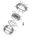
FIG. 1 is a perspective view with parts separated of an access apparatus in accordance with the principles of the present disclosure, illustrating a cannula assembly, an obturator assembly positionable within the cannula assembly and a seal assembly;FIG. 2 is an enlarged perspective view with parts separated of the seal assembly ofFIG. 1 illustrating the seal housing and the seal member;FIG. 3A is an enlarged perspective view of a flat brush profile for use as a seal member;FIG. 3B is an enlarged perspective view of a seal member formed with the flat brush profile ofFIG. 3A ;FIG. 4 is a side elevational view of an embodiment of the invention of the seal member ofFIGS. 3A-3B ;FIGS. 5-6 depict alternative brush profiles which may be used to form a seal member;FIG. 7A is a perspective view of an alternate example of a seal member having a step brush profile;FIG. 7B is a cutaway perspective view of the seal member ofFIG. 7A ;FIG. 8 is a side plan view in partial cross section of the access apparatus ofFIGS. 7A-7B ;FIG. 9 is an enlarged, partial cross-sectional view of the area of detail indicated inFIG. 8 illustrating a surgical instrument inserted through the seal assembly;FIG. 10 is a view similar toFIG. 9 illustrating the adaptability of the seal assembly to variously sized surgical instruments and radial movement of those instruments; andFIGS. 11-14 are views illustrating alternate example of seal assemblies of the present disclosure.- In the drawings and in the description which follows, the term "proximal", as is traditional, will refer to the end of the apparatus which is closest to the clinician, while the term "distal" will refer to the end which is furthest from the clinician.
- The present disclosure contemplates the introduction into a body cavity of all types of surgical instruments including clip appliers, graspers, dissectors, retractors, staplers, laser fibers, photographic devices, endoscopes and laparoscopss, tubes, and the like. All such objects are referred to herein as "instrument(s)".
- Referring now in detail to the drawing figures, in which like references numerals identify similar or identical elements, there is illustrated, in
FIG. 1 , a surgical system in accordance with the present disclosure.System 10 has particular application in laparoscopic procedures with respect to accessing the abdominal cavity, and the like, and may be used in any such surgical procedure where the peritoneal cavity is insufflated with a suitable gas, e.g., CO2, to separate the cavity wall from the internal organs housed therein.System 10 includescannula assembly 100 andobturator assembly 200, which is positionable therein. Obturator assembly 200 includesobturator 202, which includesobturator housing 204 and sleeve orouter member 206 extending therefrom.Obturator housing 204 is advantageously dimensioned for grasping by a clinician.Obturator 202 further includes penetratingmember 208 withinsleeve 206. Penetratingmember 208 punctures the abdominal cavity or the like, thereby creating an access point through which at least a portion of a surgical procedure may be conducted.Sleeve 206 may be adapted to retract upon insertion into tissue to expose penetratingmember 208 to permit the penetratingmember 208 to incise the tissue. Alternatively, penetratingmember 208 may be adapted to advance withinsleeve 206. Following penetration,obturator assembly 200 is removed fromcannula assembly 100 to permit the subsequent introduction of surgical instrumentation utilized to carry out the remainder of the procedure throughcannula assembly 100.- Referring still to
FIG. 1 ,cannula assembly 100 will be discussed. In one embodiment,cannula assembly 100 includescannula housing 102 andcannula member 104 having anouter wall 106 and defining longitudinal axis "A". Cannulamember 104 defines an internallongitudinal lumen 108 withinouter wall 106 dimensioned to permit the passage of surgical instrumentation therethrough. Either or both of cannula housing 102 andcannula member 104 may be opaque or transparent, either wholly or in part, and may be fabricated from any biocompatible material including metals or polymers. Cannulahousing 102 also incorporatescannula valve 110, and stabilizingplate 112 which secures thecannula valve 110 tocannula housing 102.Cannula valve 110 is a zero closure valve adapted to assume a substantially closed position in the absence of an instrument to prevent passage of gases therethrough. In one embodiment,cannula valve 110 is a duckbill or trumpet valve.Cannula housing 102 further includesstop cock valve 114 which is connectable to a source of insufflation fluids to distribute the fluids to the underlying body cavity. - Referring now to
FIG. 2 in conjunction withFIG. 1 ,instrument seal assembly 300 of the present disclosure is adapted to provide a substantial seal between a body cavity of a patient and the atmosphere outside the patient while an instrument is inserted through thecannula assembly 100.Seal assembly 300 may be formed integrally withcannula assembly 200, or may preferably be detachably mounted tocannula assembly 200. Additionally,seal assembly 300 may be readily adapted to be mounted to conventional cannulas of differing structures. Among other advantages, the detachability ofseal assembly 300 facilitates the removal of irregularly shaped body tissue and reduces the profile of the cannula whenever the seal assembly is unnecessary for a portion of the surgical procedure. Seal assembly 300 includesend cap 302,stabilizer plate 304,seal member 306 and sealhousing 308.End cap 302,stabilizer plate 304 and sealhousing 308 form the outer seal body ofseal assembly 100, which houses the sealing component, i.e.,seal member 306.End cap 302 is generally cylindrically-shaped and includesproximal end portion 310 defining a diameter which is less than the diameter of the remaining portion of theend cap 302, and an innerperipheral ledge 312 which supportsstabilizer plate 304.Seal housing 308 includescentral opening 314, innercylindrical portion 316 and distalouter flange 318 having a scalloped surface to facilitate handling thereof.Cylindrical portion 316 is received withinend cap 302 when theseal assembly 300 is fully assembled to enclose the sealing components.Seal housing 308 includesperipheral groove 320 and twoopposed ribs 322 extending radially inwardly adjacent thegroove 320. Groove 320 andribs 322 assist in mountingseal assembly 300 tocannula assembly 200 as will be appreciated from the description provided below.Seal housing 308 also includessecond groove 324adjacent opening 314 for accommodatingseal member 306.- Referring now to
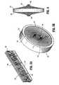
FIGS. 2 and3A-3C ,seal member 306 includessubstrate 326 and a plurality ofbristle members 328 attached to thesubstrate 326 and extending therefrom.Bristle members 328 defineaperture 330, which as will be described in greater detail below, need not be dimensioned uniformly through theseal member 306. As best depicted inFIG. 3A ,substrate 326 may be formed as a u-shaped channel such that a plurality of perpendicularly projecting bristlemembers 328 may be clamped therein by crimping the ends of the u-shaped channel. Alternatively,substrate 326 may be a strip of adhesive material, an overmolded element molded onto one end ofbristle members 328 or the like. Each bristlemember 328 thus will have asecured end 332 adjacent tosubstrate 326 and afree end 334 opposite thesecured end 332. Of course, other similar methods may be used to provide a generally flat substrate with bristlemembers 328 projecting perpendicularly from a single face of the substrate. This arrangement defines a flat brush profile wherein all bristle members are generally the same length. A generally flat surface is formed by the free ends 334 of thebristle members 328 being generally parallel tosubstrate 326. Bristle members 328 are preferably fabricated from an elastomeric material such as synthetic or natural rubber which is preferably sufficiently resilient to accommodate and provide a substantial seal with instruments of varying diameters. The geometry ofbristle members 328 is preferably long and slender.Flat substrate 326 is curved to form a generally round ring structure to provideseal member 306 generally as seen inFIG. 3B . With this arrangement ofsubstrate 326, bristlemember 328 are directed radially inwardly to defineaperture 330 withfree ends 334 of thebristle members 328 in close proximity with each other as compared to secured ends 332 of thebristle members 328 which substantially maintain their spacing near thesubstrate 326. This congregation of free ends 334 ofbristle member 328 can result in a higher bristle density at the center of the ring nearaperture 330 than at the outer regions nearsubstrate 326. If the number and geometry ofbristle member 328 is sufficient, a saturation point may be reached where free ends 334 of thebristle member 328 require more space than is available within the confines of the cylinder defined by thesubstrate 326 thereby resulting inopposed bulges 336 formed near the center of the ring as can be seen in the alternate embodiment ofFIG. 4 whereby free ends 334 have an axial component of direction corresponding to the invention as claimed.Seal member 306 arranged in this manner can provide robust lateral support for relatively small instruments having outer dimensions approximating the diameter ofaperture 330.- To provide for a decreased insertion force, particularly for larger instruments, several alternate brush profiles may be considered. For example, a tapered brush profile, as shown in
FIG. 5 , can produce a seal member having a lower required insertion force for larger instruments. This is because fewer bristles will need to compete for the limited space near theaperture 330, and fewer bristles will need to bend to accommodate the instrument. This arrangement is characterized by a brush profile which is uniform along the length of thesubstrate 326 with a decreasing bristle cross-sectional dimension in the direction of the free ends of the bristles. Depending on the decrease in bristle cross-section, when this profile is formed into a ring, any bulge created in the case of the straight brush profile may be reduced or eliminated resulting in a relatively thin seal member. - Alternatively, a saw-tooth brush profile as shown in
FIG. 6 may be provided. The saw-tooth profile is characterized bybristle members 328 arranged in groups or sets 350 shaped to form a triangular arrangement along the length of the substrate 130. Eachseries 350 has a base 352 formed by the secured ends ofbristle members 328,vertex 354, and twosides 356 formed by the free ends of thebristle members 328. As thesubstrate 326 is formed into a round ring shape, the triangular teeth will begin to converge as the bristles begin to compete for space. Only the longestbristles forming vertex 354 will reach the center of the ring to define the aperture of the seal thereby resulting in a reduced bristle density at the center of the ring. At several internal diameters of the ring, the free ends of the bristles forming the sides of the triangular arrangement will tend to congregate forming multiple bands where relatively robust lateral support will be provided. - Referring now to
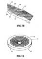
FIGS. 7A and 7B , a stepped brush profile may be provided to create interior rings of high bristle density at the free ends of the bristles and corresponding lateral stiffness. This profile is characterized by bristles of several discrete lengths protruding from the substrate and arranged in distinct steps. The profile depicted inFIGS. 7A and 7B ofseal member 400 includes seven distinct linear levels or annular steps. Preferably, the longest bristles members are centrally located extending from the center of thesubstrate 402 to form thetallest step 404 with theshorter steps step - Referring to
FIGS. 8 and 9 ,seal member 400 ofFIGS. 7A and 7B is shown mounted tocannula assembly 200. An elongated object such as a surgical instrument, identified generally by reference numeral "i" may be inserted throughcentral aperture 412 ofseal assembly 400 and thecannula assembly 200 to perform the desired surgical procedure. As the surgical instrument "i" entersseal assembly 400, the tip of the surgical instrument "i" is engaged by the bristle members of theseal assembly 400. In one arrangement, first (most proximal)step 406 of bristles does not engage the instrument, and thesecond step 408 of bristles engages the instrument without substantial bending.Steps proximal step 408 of bristles provides a robust lateral support for the instrument whilesteps seal assembly 400. The ease of instrument passage is further enhanced by the arrangement of the bristle members into a stepped profile because no force is required to pivot the bristle members forming the shortest steps on the proximal end of the seal member, and a reduced force is required to pivot any corresponding steps on the distal end of the seal member which only need to pivot in order to accommodate the displacement of the longer bristles actually forming the fluid-tight seal about the instrument. Instrument "i" is advanced through thecannula assembly 200 whereby the duck-bill seal 208 of thecannula 200 also spreads to allow passage of instrument i. Once positioned within the instrument-seal 400 andcannula assembly 200, surgical instrument "i" may be maneuvered about the internal body cavity. - Referring now to
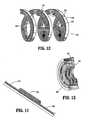
FIG. 10 , surgical instrument "i" is shown having a lateral offset relative to the central longitudinal axis "k". Theseal assembly 100 permits limited unencumbered movement of instrument "i" in a lateral direction (relative to the central longitudinal axis) while maintaining an adequate seal about the instrument. Thus, manipulation of the instrument in any direction, either, longitudinally or radially, will not affect the integrity of the seal, since the resilient material of sealingmember 110 will conform to the movements of the instrument and assume a shape necessary to retain a sealing contact with the instrument. FIGS. 11-13 illustrate another alternate example of a seal member.Seal member 500 illustrates a flat brush design incorporating bristlemembers substrate 506. In particular, bristlemembers 502 have a length which is less then the lengths ofbristle members 504. In one embodiment, bristlemembers 504 are centrally located. In the alternative, bristlemembers bristle members substrate 506 is wound for placement in the seal housing,seal member 500 defines a multilayer arrangement of bristle members with varying aperture sizes due to the varied lengths ofbristles 502, 504 (seeFIG. 13 ).FIG. 14 illustrates an alternate example of the seal member. In accordance with this embodiment, seal member 600 includessubstrate 602 and bristlemembers 604.Bristle members 604 are of constant length.Substrate 602 is arranged such that the outer diameter of thesubstrate 602 is varied. This arrangement allows for portions of the seal member to expand axially (here the center coil or substrate 602) as the instrument is inserted.FIG. 15 is another example whereseal member 700 has a series of triangular-shaped bristlearrangements 702. Each bristlearrangement 702 includes a plurality of steps having a central locatedstep 704, firstlateral steps 706 on each side of the central locatedstep 704 and secondlateral steps 708 adjacent respective first lateral steps 706.Seal member 700 formed from this profile is capable of providing high lateral support in predetermined diameters while maintaining a low insertion force.FIG. 16 shows aseal member 800 created from a stack of substantially flatflexible components 802 having various inner diameters. Eachcomponent 802 may have a substrate around its outer circumference where the component is substantially solid. Relatively large, roughly triangular-shapedelements 804 are disposed between a plurality ofslits 806 extending through the components. The components are stacked or in superposed relation such thatelements 804 andslits 806 are staggered whereby no continuous linear passage extends throughseal member 800.Elements 804 may be formed of bristles or alternatively fabricated from a suitable solid elastomeric material.- Although the foregoing disclosure has been described in some detail by way of illustration and example, for purposes of clarity or understanding, it will be obvious that certain changes and modifications may be practiced within the scope of the appended claims.
Claims (7)
- A surgical access assembly (10) for sealed reception of an elongated object, which comprises:an access member (300) having at least one opening (314) configured and dimensioned to permit entry of an elongated object and defining a central longitudinal axis, the access member (300) adapted for positioning within tissue to provide access to an underlying surgical site; anda seal member (306) mounted relative to the access member (300), the seal member (306) including an outer substrate (326) and a plurality of flexible bristle members (328) extending radially inwardly from the outer substrate (326) toward the central longitudinal axis, the bristle members (328) defining free ends (334) remote from the outer substrate (326) and being adapted to flex and form a substantial seal about the elongated object,characterized bythe free ends (334) of the bristle members (328) having an axial component of direction with respect to the central longitudinal axis in the absence of the elongated object.
- The surgical access apparatus (10) according to claim 1 therein the bristle members (328) are dimensioned to define a thickness or density which is greater at the free ends (334) thereof relative to remaining portions of the bristle members (328).
- The surgical access assembly (10) according to any one of the preceding claims wherein the bristle members (328) are arranged to define a varying degree of density of the seal member (306) adjacent the free ends of the bristle members (328) to affect at least one of insertion force or lateral stability of the seal member (306).
- The surgical access assembly (10) according to any one of the preceding claims wherein the bristle members (328) are arranged to define a bulge (336) adjacent the central longitudinal axis.
- The surgical access assembly (10) according to any one of the preceding claims wherein the bristle members (328) are arranged to define opposed bulges (336) adjacent the central longitudinal axis.
- The surgical access assembly (10) according to any one of the preceding claims wherein the bristle members (328) are arranged to define an aperture.
- The surgical access assembly (10) according to any one of the preceding claims wherein the free ends (334) of the bristle members (328) are arranged to extend in a general axial direction relative to the central longitudinal axis.
Applications Claiming Priority (1)
| Application Number | Priority Date | Filing Date | Title |
|---|---|---|---|
| US93125407P | 2007-05-22 | 2007-05-22 |
Publications (3)
| Publication Number | Publication Date |
|---|---|
| EP1997444A2 EP1997444A2 (en) | 2008-12-03 |
| EP1997444A3 EP1997444A3 (en) | 2008-12-10 |
| EP1997444B1true EP1997444B1 (en) | 2011-09-14 |
Family
ID=39865146
Family Applications (1)
| Application Number | Title | Priority Date | Filing Date |
|---|---|---|---|
| EP08251759ANot-in-forceEP1997444B1 (en) | 2007-05-22 | 2008-05-20 | Access assembly with whisker seal |
Country Status (6)
| Country | Link |
|---|---|
| US (1) | US20080290605A1 (en) |
| EP (1) | EP1997444B1 (en) |
| JP (1) | JP2008289884A (en) |
| AU (1) | AU2008202234B2 (en) |
| CA (1) | CA2631609A1 (en) |
| ES (1) | ES2373072T3 (en) |
Families Citing this family (12)
| Publication number | Priority date | Publication date | Assignee | Title |
|---|---|---|---|---|
| US8343041B2 (en)* | 2008-05-19 | 2013-01-01 | Boston Scientific Scimed, Inc. | Integrated locking device with passive sealing |
| US20100261969A1 (en)* | 2009-04-14 | 2010-10-14 | Tyco Healthcare Group Lp | Vibrating seal for a surgical trocar apparatus |
| IT1395219B1 (en)* | 2009-05-19 | 2012-09-05 | Ab Medica Spa | SHUTTER FOR TROCAR AND ITS TROCAR. |
| US10349821B2 (en)* | 2011-03-01 | 2019-07-16 | Sanovas Intellectual Property, Llc | Cleaning system for medical imaging device |
| US20130020770A1 (en)* | 2011-07-18 | 2013-01-24 | Jimmie Wade Hamilton | Brush seal |
| WO2013123455A1 (en) | 2012-02-15 | 2013-08-22 | Intuitive Surgical Operations, Inc. | Low friction cannula seals for minimally invasive robotic surgery |
| US9572626B2 (en) | 2013-02-15 | 2017-02-21 | Intuitive Surgical Operations, Inc. | Actuated cannula seal |
| USD886253S1 (en)* | 2018-03-15 | 2020-06-02 | Garlock Pipeline Technologies, Llc | Gasket |
| KR101939733B1 (en)* | 2015-03-09 | 2019-01-18 | 이구루코교 가부시기가이샤 | Split-type brush seal device, brush seal piece, and method of assembling the split-type brush seal device |
| DE102015219946A1 (en)* | 2015-10-14 | 2017-04-20 | Siemens Aktiengesellschaft | Brush seal and turbo machine with brush seal |
| WO2019033006A1 (en)* | 2017-08-11 | 2019-02-14 | Boston Scientific Scimed, Inc. | Biopsy cap for use with endoscope |
| EP3817637B1 (en) | 2018-11-02 | 2023-10-25 | Boston Scientific Medical Device Limited | Devices for providing sealable access to a working channel |
Family Cites Families (39)
| Publication number | Priority date | Publication date | Assignee | Title |
|---|---|---|---|---|
| US4779904A (en)* | 1986-10-31 | 1988-10-25 | Rich Christopher K | Couplings for connecting vehicle exhaust tail pipes to exhaust conduits for removing vehicle exhaust gases |
| US5395342A (en)* | 1990-07-26 | 1995-03-07 | Yoon; Inbae | Endoscopic portal |
| US5389080A (en)* | 1990-07-26 | 1995-02-14 | Yoon; Inbae | Endoscopic portal for use in endoscopic procedures and methods therefor |
| US5429609A (en)* | 1990-07-26 | 1995-07-04 | Yoon; Inbae | Endoscopic portal for use in endoscopic procedures and methods therefor |
| GB9103459D0 (en)* | 1991-02-19 | 1991-04-03 | Cross Mfg Co | Brush seal assembly |
| US5180373A (en)* | 1991-06-07 | 1993-01-19 | United States Surgical Corporation | Valve system for introducing objects into anatomical body portions |
| US5385553A (en)* | 1991-07-18 | 1995-01-31 | Applied Medical Resources Corporation | Trocar with floating septum seal |
| US5545142A (en)* | 1991-10-18 | 1996-08-13 | Ethicon, Inc. | Seal members for surgical trocars |
| CA2093748C (en)* | 1992-04-24 | 1996-11-12 | Roy D. Gravener | Valve assembly for introducing instruments into body cavities |
| US5397314A (en)* | 1992-10-09 | 1995-03-14 | Farley; Kevin | Surgical cannula with ball valve |
| US5356394A (en)* | 1992-10-09 | 1994-10-18 | Kevin Farley | Cannula with ball valve |
| US5476475A (en)* | 1992-11-23 | 1995-12-19 | Applied Medical Resources | Trocar with universal seal protector |
| US5743884A (en)* | 1992-12-17 | 1998-04-28 | Hasson; Harrith M. | Sealing structure for medical instrument |
| US5514098A (en)* | 1993-02-04 | 1996-05-07 | Owens Precision Systems, Inc. | Caps for sealing a cannula assembly |
| US5411483A (en)* | 1993-02-10 | 1995-05-02 | Origin Medsystems, Inc. | Gas-tight seal accommodating surgical instruments with a wide range of diameters |
| US5407433A (en)* | 1993-02-10 | 1995-04-18 | Origin Medsystems, Inc. | Gas-tight seal accommodating surgical instruments with a wide range of diameters |
| US5657963A (en)* | 1993-06-16 | 1997-08-19 | United States Surgical Corporation | Seal assembly for accommodating introduction of surgical instruments |
| CA2126150C (en)* | 1993-07-14 | 2005-02-22 | David T. Green | Seal assembly for accommodating introduction of surgical instruments |
| US5391154A (en)* | 1993-08-30 | 1995-02-21 | United States Surgical Corporation | Trocar seal system |
| US5944697A (en)* | 1994-05-31 | 1999-08-31 | Universal Medical Instrument Corp. | Percutaneous catheter introducer |
| US5603702A (en)* | 1994-08-08 | 1997-02-18 | United States Surgical Corporation | Valve system for cannula assembly |
| US5752938A (en)* | 1994-09-12 | 1998-05-19 | Richard-Allan Medical Industries, Inc. | Seal for surgical instruments |
| US5997515A (en)* | 1995-05-19 | 1999-12-07 | General Surgical Innovations, Inc. | Screw-type skin seal with inflatable membrane |
| US5814026A (en)* | 1996-03-19 | 1998-09-29 | Yoon; Inbae | Endoscopic portal having a universal seal and methods for introducing instruments therethrough |
| US5788676A (en)* | 1996-03-25 | 1998-08-04 | Yoon; Inbae | Endoscopic portal having multiple universal seals and method of introducing instruments therethrough |
| US6066117A (en)* | 1996-06-11 | 2000-05-23 | Endolap, Inc. | Cannula flapper valve assembly |
| US5820604A (en)* | 1996-06-11 | 1998-10-13 | Endolap, Inc. | Cannula cap including yeildable outer seal and flapper valve |
| US5906595A (en)* | 1997-04-25 | 1999-05-25 | Ethicon Endo-Surgery, Inc. | Trocar having protector with flexible end and improved seal assembly |
| ES2333616T3 (en)* | 1997-05-02 | 2010-02-24 | Tyco Healthcare Group Lp | CANULA ASSEMBLY |
| EP2111884A1 (en)* | 1997-05-28 | 2009-10-28 | United States Surgical Corporation | Trocar seal system |
| US5916198A (en)* | 1997-08-05 | 1999-06-29 | Femrx, Inc. | Non-binding surgical valve |
| US5989224A (en)* | 1998-02-23 | 1999-11-23 | Dexide Corporation | Universal seal for use with endoscopic cannula |
| US6402748B1 (en)* | 1998-09-23 | 2002-06-11 | Sherwood Services Ag | Electrosurgical device having a dielectrical seal |
| US6860869B2 (en)* | 1999-03-26 | 2005-03-01 | William G. Dennis | Surgical instrument seal assembly |
| US6258065B1 (en)* | 1999-03-26 | 2001-07-10 | Core Dynamics, Inc. | Surgical instrument seal assembly |
| US6595946B1 (en)* | 2000-02-25 | 2003-07-22 | United States Surgical Corporation | Valve assembly |
| WO2002030305A2 (en)* | 2000-10-13 | 2002-04-18 | Tyco Healthcare Group Lp | Valve assembly including diameter reduction structure for trocar |
| US6942671B1 (en)* | 2000-11-06 | 2005-09-13 | Tyco Healthcare Group Lp | Surgical sealing apparatus |
| JP4213398B2 (en)* | 2002-04-15 | 2009-01-21 | 株式会社東芝 | Brush seal |
- 2008
- 2008-05-20EPEP08251759Apatent/EP1997444B1/ennot_activeNot-in-force
- 2008-05-20ESES08251759Tpatent/ES2373072T3/enactiveActive
- 2008-05-20CACA002631609Apatent/CA2631609A1/ennot_activeAbandoned
- 2008-05-21AUAU2008202234Apatent/AU2008202234B2/ennot_activeCeased
- 2008-05-21JPJP2008133621Apatent/JP2008289884A/enactivePending
- 2008-05-21USUS12/124,346patent/US20080290605A1/ennot_activeAbandoned
Also Published As
| Publication number | Publication date |
|---|---|
| EP1997444A2 (en) | 2008-12-03 |
| AU2008202234A1 (en) | 2008-12-11 |
| ES2373072T3 (en) | 2012-01-31 |
| CA2631609A1 (en) | 2008-11-22 |
| EP1997444A3 (en) | 2008-12-10 |
| AU2008202234B2 (en) | 2013-09-19 |
| JP2008289884A (en) | 2008-12-04 |
| US20080290605A1 (en) | 2008-11-27 |
Similar Documents
| Publication | Publication Date | Title |
|---|---|---|
| EP1997444B1 (en) | Access assembly with whisker seal | |
| US8864659B2 (en) | Seal anchor for use in surgical procedures | |
| US8206294B2 (en) | Surgical access device with flexible seal channel | |
| US8932212B2 (en) | Seal anchor with non-parallel lumens | |
| EP1992298B1 (en) | Flexible cannula with associated seal | |
| WO2014116889A1 (en) | Surgical seal assembly including an overlapping guard structure for a seal | |
| EP2769691A1 (en) | Flexible access assembly | |
| EP2684532A2 (en) | Surgical seal assembly including a guard member | |
| EP1889580A2 (en) | Surgical seal assembly | |
| EP2229899A1 (en) | Access port including centering feature | |
| EP2110088B1 (en) | Self-conforming surgical seal | |
| US9585690B2 (en) | Surgical access device including universal seal mechanism associated with bellows | |
| EP3698741A1 (en) | Access assembly including flexible cannula | |
| AU2013263702B2 (en) | Seal anchor for use in surgical procedures |
Legal Events
| Date | Code | Title | Description |
|---|---|---|---|
| PUAI | Public reference made under article 153(3) epc to a published international application that has entered the european phase | Free format text:ORIGINAL CODE: 0009012 | |
| PUAL | Search report despatched | Free format text:ORIGINAL CODE: 0009013 | |
| AK | Designated contracting states | Kind code of ref document:A2 Designated state(s):AT BE BG CH CY CZ DE DK EE ES FI FR GB GR HR HU IE IS IT LI LT LU LV MC MT NL NO PL PT RO SE SI SK TR | |
| AX | Request for extension of the european patent | Extension state:AL BA MK RS | |
| AK | Designated contracting states | Kind code of ref document:A3 Designated state(s):AT BE BG CH CY CZ DE DK EE ES FI FR GB GR HR HU IE IS IT LI LT LU LV MC MT NL NO PL PT RO SE SI SK TR | |
| AX | Request for extension of the european patent | Extension state:AL BA MK RS | |
| RIC1 | Information provided on ipc code assigned before grant | Ipc:A61B 17/34 20060101AFI20081029BHEP Ipc:F16J 15/32 20060101ALI20081031BHEP Ipc:A61B 17/32 20060101ALN20081031BHEP | |
| 17P | Request for examination filed | Effective date:20090512 | |
| 17Q | First examination report despatched | Effective date:20090616 | |
| AKX | Designation fees paid | Designated state(s):DE ES FR GB IE IT | |
| GRAP | Despatch of communication of intention to grant a patent | Free format text:ORIGINAL CODE: EPIDOSNIGR1 | |
| GRAS | Grant fee paid | Free format text:ORIGINAL CODE: EPIDOSNIGR3 | |
| GRAA | (expected) grant | Free format text:ORIGINAL CODE: 0009210 | |
| AK | Designated contracting states | Kind code of ref document:B1 Designated state(s):DE ES FR GB IE IT | |
| REG | Reference to a national code | Ref country code:GB Ref legal event code:FG4D | |
| REG | Reference to a national code | Ref country code:IE Ref legal event code:FG4D | |
| REG | Reference to a national code | Ref country code:DE Ref legal event code:R096 Ref document number:602008009758 Country of ref document:DE Effective date:20111110 | |
| RAP2 | Party data changed (patent owner data changed or rights of a patent transferred) | Owner name:TYCO HEALTHCARE GROUP LP | |
| REG | Reference to a national code | Ref country code:ES Ref legal event code:FG2A Ref document number:2373072 Country of ref document:ES Kind code of ref document:T3 Effective date:20120131 | |
| PLBE | No opposition filed within time limit | Free format text:ORIGINAL CODE: 0009261 | |
| STAA | Information on the status of an ep patent application or granted ep patent | Free format text:STATUS: NO OPPOSITION FILED WITHIN TIME LIMIT | |
| 26N | No opposition filed | Effective date:20120615 | |
| REG | Reference to a national code | Ref country code:DE Ref legal event code:R097 Ref document number:602008009758 Country of ref document:DE Effective date:20120615 | |
| PGFP | Annual fee paid to national office [announced via postgrant information from national office to epo] | Ref country code:ES Payment date:20120528 Year of fee payment:5 | |
| PGFP | Annual fee paid to national office [announced via postgrant information from national office to epo] | Ref country code:IE Payment date:20130528 Year of fee payment:6 Ref country code:DE Payment date:20130530 Year of fee payment:6 Ref country code:GB Payment date:20130528 Year of fee payment:6 | |
| PGFP | Annual fee paid to national office [announced via postgrant information from national office to epo] | Ref country code:FR Payment date:20130606 Year of fee payment:6 Ref country code:IT Payment date:20130522 Year of fee payment:6 | |
| REG | Reference to a national code | Ref country code:DE Ref legal event code:R119 Ref document number:602008009758 Country of ref document:DE | |
| GBPC | Gb: european patent ceased through non-payment of renewal fee | Effective date:20140520 | |
| REG | Reference to a national code | Ref country code:IE Ref legal event code:MM4A | |
| REG | Reference to a national code | Ref country code:FR Ref legal event code:ST Effective date:20150130 | |
| REG | Reference to a national code | Ref country code:DE Ref legal event code:R119 Ref document number:602008009758 Country of ref document:DE Effective date:20141202 | |
| PG25 | Lapsed in a contracting state [announced via postgrant information from national office to epo] | Ref country code:DE Free format text:LAPSE BECAUSE OF NON-PAYMENT OF DUE FEES Effective date:20141202 Ref country code:IT Free format text:LAPSE BECAUSE OF NON-PAYMENT OF DUE FEES Effective date:20140520 Ref country code:IE Free format text:LAPSE BECAUSE OF NON-PAYMENT OF DUE FEES Effective date:20140520 | |
| PG25 | Lapsed in a contracting state [announced via postgrant information from national office to epo] | Ref country code:FR Free format text:LAPSE BECAUSE OF NON-PAYMENT OF DUE FEES Effective date:20140602 Ref country code:GB Free format text:LAPSE BECAUSE OF NON-PAYMENT OF DUE FEES Effective date:20140520 | |
| REG | Reference to a national code | Ref country code:ES Ref legal event code:FD2A Effective date:20150630 | |
| PG25 | Lapsed in a contracting state [announced via postgrant information from national office to epo] | Ref country code:ES Free format text:LAPSE BECAUSE OF NON-PAYMENT OF DUE FEES Effective date:20140521 |