EP1997438B1 - Pneumatically powered surgical cutting and fastening instrument with electrical control and recording mechanisms - Google Patents
Pneumatically powered surgical cutting and fastening instrument with electrical control and recording mechanismsDownload PDFInfo
- Publication number
- EP1997438B1 EP1997438B1EP08251885.3AEP08251885AEP1997438B1EP 1997438 B1EP1997438 B1EP 1997438B1EP 08251885 AEP08251885 AEP 08251885AEP 1997438 B1EP1997438 B1EP 1997438B1
- Authority
- EP
- European Patent Office
- Prior art keywords
- sensor
- instrument
- closure
- trigger
- valve
- Prior art date
- Legal status (The legal status is an assumption and is not a legal conclusion. Google has not performed a legal analysis and makes no representation as to the accuracy of the status listed.)
- Not-in-force
Links
- 230000007246mechanismEffects0.000titleclaimsdescription60
- 238000005520cutting processMethods0.000titleclaimsdescription45
- 238000010304firingMethods0.000claimsdescription100
- 239000012636effectorSubstances0.000claimsdescription84
- 238000004891communicationMethods0.000claimsdescription20
- 238000000034methodMethods0.000claimsdescription17
- 238000012544monitoring processMethods0.000claimsdescription5
- 239000007789gasSubstances0.000description110
- 230000004913activationEffects0.000description50
- 230000033001locomotionEffects0.000description22
- 208000006011StrokeDiseases0.000description21
- 230000000007visual effectEffects0.000description13
- 230000008859changeEffects0.000description12
- 230000006870functionEffects0.000description12
- 238000005259measurementMethods0.000description12
- 230000014759maintenance of locationEffects0.000description9
- 230000004044responseEffects0.000description8
- 239000000853adhesiveSubstances0.000description6
- 230000001070adhesive effectEffects0.000description6
- CURLTUGMZLYLDI-UHFFFAOYSA-NCarbon dioxideChemical compoundO=C=OCURLTUGMZLYLDI-UHFFFAOYSA-N0.000description4
- 238000005452bendingMethods0.000description4
- 230000008901benefitEffects0.000description4
- 238000001356surgical procedureMethods0.000description4
- 238000004140cleaningMethods0.000description3
- 238000013461designMethods0.000description3
- 238000010586diagramMethods0.000description3
- 230000008713feedback mechanismEffects0.000description3
- 239000012530fluidSubstances0.000description3
- 239000000463materialSubstances0.000description3
- 230000004048modificationEffects0.000description3
- 238000012986modificationMethods0.000description3
- 229920000642polymerPolymers0.000description3
- 230000005855radiationEffects0.000description3
- 230000000717retained effectEffects0.000description3
- 230000002441reversible effectEffects0.000description3
- YFMFNYKEUDLDTL-UHFFFAOYSA-N1,1,1,2,3,3,3-heptafluoropropaneChemical compoundFC(F)(F)C(F)C(F)(F)FYFMFNYKEUDLDTL-UHFFFAOYSA-N0.000description2
- XKRFYHLGVUSROY-UHFFFAOYSA-NArgonChemical compound[Ar]XKRFYHLGVUSROY-UHFFFAOYSA-N0.000description2
- IJGRMHOSHXDMSA-UHFFFAOYSA-NAtomic nitrogenChemical compoundN#NIJGRMHOSHXDMSA-UHFFFAOYSA-N0.000description2
- LCGLNKUTAGEVQW-UHFFFAOYSA-NDimethyl etherChemical compoundCOCLCGLNKUTAGEVQW-UHFFFAOYSA-N0.000description2
- GQPLMRYTRLFLPF-UHFFFAOYSA-NNitrous OxideChemical compound[O-][N+]#NGQPLMRYTRLFLPF-UHFFFAOYSA-N0.000description2
- ATUOYWHBWRKTHZ-UHFFFAOYSA-NPropaneChemical compoundCCCATUOYWHBWRKTHZ-UHFFFAOYSA-N0.000description2
- 230000006978adaptationEffects0.000description2
- 230000004075alterationEffects0.000description2
- 238000004458analytical methodMethods0.000description2
- 229910002092carbon dioxideInorganic materials0.000description2
- 239000001569carbon dioxideSubstances0.000description2
- 239000003086colorantSubstances0.000description2
- 230000006835compressionEffects0.000description2
- 238000007906compressionMethods0.000description2
- 230000007423decreaseEffects0.000description2
- 239000003989dielectric materialSubstances0.000description2
- 230000000694effectsEffects0.000description2
- 229920001746electroactive polymerPolymers0.000description2
- NNPPMTNAJDCUHE-UHFFFAOYSA-NisobutaneChemical compoundCC(C)CNNPPMTNAJDCUHE-UHFFFAOYSA-N0.000description2
- 239000004973liquid crystal related substanceSubstances0.000description2
- 238000005192partitionMethods0.000description2
- 230000008569processEffects0.000description2
- 238000003860storageMethods0.000description2
- 238000003466weldingMethods0.000description2
- LVGUZGTVOIAKKC-UHFFFAOYSA-N1,1,1,2-tetrafluoroethaneChemical compoundFCC(F)(F)FLVGUZGTVOIAKKC-UHFFFAOYSA-N0.000description1
- 241000894006BacteriaSpecies0.000description1
- XOBKSJJDNFUZPF-UHFFFAOYSA-NMethoxyethaneChemical compoundCCOCXOBKSJJDNFUZPF-UHFFFAOYSA-N0.000description1
- KEAYESYHFKHZAL-UHFFFAOYSA-NSodiumChemical compound[Na]KEAYESYHFKHZAL-UHFFFAOYSA-N0.000description1
- 239000004775TyvekSubstances0.000description1
- 229920000690TyvekPolymers0.000description1
- 241000405217Viola <butterfly>Species0.000description1
- 230000009471actionEffects0.000description1
- 230000001154acute effectEffects0.000description1
- 238000004873anchoringMethods0.000description1
- 229910052786argonInorganic materials0.000description1
- QVGXLLKOCUKJST-UHFFFAOYSA-Natomic oxygenChemical compound[O]QVGXLLKOCUKJST-UHFFFAOYSA-N0.000description1
- 238000009530blood pressure measurementMethods0.000description1
- 239000001273butaneSubstances0.000description1
- 238000006243chemical reactionMethods0.000description1
- 238000010276constructionMethods0.000description1
- 238000013500data storageMethods0.000description1
- 230000007547defectEffects0.000description1
- 238000006073displacement reactionMethods0.000description1
- 238000009826distributionMethods0.000description1
- 230000005611electricityEffects0.000description1
- 230000012447hatchingEffects0.000description1
- 239000001307heliumSubstances0.000description1
- 229910052734heliumInorganic materials0.000description1
- SWQJXJOGLNCZEY-UHFFFAOYSA-Nhelium atomChemical compound[He]SWQJXJOGLNCZEY-UHFFFAOYSA-N0.000description1
- 238000003780insertionMethods0.000description1
- 230000037431insertionEffects0.000description1
- 239000001282iso-butaneSubstances0.000description1
- 239000011159matrix materialSubstances0.000description1
- 239000002991molded plasticSubstances0.000description1
- IJDNQMDRQITEOD-UHFFFAOYSA-Nn-butaneChemical compoundCCCCIJDNQMDRQITEOD-UHFFFAOYSA-N0.000description1
- OFBQJSOFQDEBGM-UHFFFAOYSA-Nn-pentaneNatural productsCCCCCOFBQJSOFQDEBGM-UHFFFAOYSA-N0.000description1
- 230000007935neutral effectEffects0.000description1
- 229910052757nitrogenInorganic materials0.000description1
- 239000001272nitrous oxideSubstances0.000description1
- 239000001301oxygenSubstances0.000description1
- 229910052760oxygenInorganic materials0.000description1
- 239000004033plasticSubstances0.000description1
- 238000005381potential energyMethods0.000description1
- 238000003825pressingMethods0.000description1
- 239000001294propaneSubstances0.000description1
- 230000009467reductionEffects0.000description1
- 238000012958reprocessingMethods0.000description1
- 239000004065semiconductorSubstances0.000description1
- 239000012312sodium hydrideSubstances0.000description1
- 229910000104sodium hydrideInorganic materials0.000description1
- 239000007787solidSubstances0.000description1
- 230000001954sterilising effectEffects0.000description1
- 238000004659sterilization and disinfectionMethods0.000description1
- 238000012546transferMethods0.000description1
- 230000001131transforming effectEffects0.000description1
- 238000011144upstream manufacturingMethods0.000description1
Images


Classifications
- A—HUMAN NECESSITIES
- A61—MEDICAL OR VETERINARY SCIENCE; HYGIENE
- A61B—DIAGNOSIS; SURGERY; IDENTIFICATION
- A61B17/00—Surgical instruments, devices or methods
- A61B17/068—Surgical staplers, e.g. containing multiple staples or clamps
- A61B17/072—Surgical staplers, e.g. containing multiple staples or clamps for applying a row of staples in a single action, e.g. the staples being applied simultaneously
- A61B17/07207—Surgical staplers, e.g. containing multiple staples or clamps for applying a row of staples in a single action, e.g. the staples being applied simultaneously the staples being applied sequentially
- A—HUMAN NECESSITIES
- A61—MEDICAL OR VETERINARY SCIENCE; HYGIENE
- A61B—DIAGNOSIS; SURGERY; IDENTIFICATION
- A61B34/00—Computer-aided surgery; Manipulators or robots specially adapted for use in surgery
- A61B34/70—Manipulators specially adapted for use in surgery
- A61B34/71—Manipulators operated by drive cable mechanisms
- A—HUMAN NECESSITIES
- A61—MEDICAL OR VETERINARY SCIENCE; HYGIENE
- A61B—DIAGNOSIS; SURGERY; IDENTIFICATION
- A61B17/00—Surgical instruments, devices or methods
- A61B2017/00017—Electrical control of surgical instruments
- A61B2017/00115—Electrical control of surgical instruments with audible or visual output
- A61B2017/00128—Electrical control of surgical instruments with audible or visual output related to intensity or progress of surgical action
- A—HUMAN NECESSITIES
- A61—MEDICAL OR VETERINARY SCIENCE; HYGIENE
- A61B—DIAGNOSIS; SURGERY; IDENTIFICATION
- A61B17/00—Surgical instruments, devices or methods
- A61B2017/00017—Electrical control of surgical instruments
- A61B2017/00199—Electrical control of surgical instruments with a console, e.g. a control panel with a display
- A—HUMAN NECESSITIES
- A61—MEDICAL OR VETERINARY SCIENCE; HYGIENE
- A61B—DIAGNOSIS; SURGERY; IDENTIFICATION
- A61B17/00—Surgical instruments, devices or methods
- A61B2017/00367—Details of actuation of instruments, e.g. relations between pushing buttons, or the like, and activation of the tool, working tip, or the like
- A61B2017/00398—Details of actuation of instruments, e.g. relations between pushing buttons, or the like, and activation of the tool, working tip, or the like using powered actuators, e.g. stepper motors, solenoids
- A—HUMAN NECESSITIES
- A61—MEDICAL OR VETERINARY SCIENCE; HYGIENE
- A61B—DIAGNOSIS; SURGERY; IDENTIFICATION
- A61B17/00—Surgical instruments, devices or methods
- A61B2017/00535—Surgical instruments, devices or methods pneumatically or hydraulically operated
- A61B2017/00544—Surgical instruments, devices or methods pneumatically or hydraulically operated pneumatically
- A—HUMAN NECESSITIES
- A61—MEDICAL OR VETERINARY SCIENCE; HYGIENE
- A61B—DIAGNOSIS; SURGERY; IDENTIFICATION
- A61B17/00—Surgical instruments, devices or methods
- A61B17/068—Surgical staplers, e.g. containing multiple staples or clamps
- A61B17/072—Surgical staplers, e.g. containing multiple staples or clamps for applying a row of staples in a single action, e.g. the staples being applied simultaneously
- A61B2017/07214—Stapler heads
- A—HUMAN NECESSITIES
- A61—MEDICAL OR VETERINARY SCIENCE; HYGIENE
- A61B—DIAGNOSIS; SURGERY; IDENTIFICATION
- A61B17/00—Surgical instruments, devices or methods
- A61B17/28—Surgical forceps
- A61B17/29—Forceps for use in minimally invasive surgery
- A61B2017/2926—Details of heads or jaws
- A61B2017/2927—Details of heads or jaws the angular position of the head being adjustable with respect to the shaft
- A61B2017/2929—Details of heads or jaws the angular position of the head being adjustable with respect to the shaft with a head rotatable about the longitudinal axis of the shaft
- A—HUMAN NECESSITIES
- A61—MEDICAL OR VETERINARY SCIENCE; HYGIENE
- A61B—DIAGNOSIS; SURGERY; IDENTIFICATION
- A61B90/00—Instruments, implements or accessories specially adapted for surgery or diagnosis and not covered by any of the groups A61B1/00 - A61B50/00, e.g. for luxation treatment or for protecting wound edges
- A61B90/06—Measuring instruments not otherwise provided for
- A61B2090/064—Measuring instruments not otherwise provided for for measuring force, pressure or mechanical tension
- A—HUMAN NECESSITIES
- A61—MEDICAL OR VETERINARY SCIENCE; HYGIENE
- A61B—DIAGNOSIS; SURGERY; IDENTIFICATION
- A61B90/00—Instruments, implements or accessories specially adapted for surgery or diagnosis and not covered by any of the groups A61B1/00 - A61B50/00, e.g. for luxation treatment or for protecting wound edges
- A61B90/08—Accessories or related features not otherwise provided for
- A61B2090/0807—Indication means
- A61B2090/0811—Indication means for the position of a particular part of an instrument with respect to the rest of the instrument, e.g. position of the anvil of a stapling instrument
- A—HUMAN NECESSITIES
- A61—MEDICAL OR VETERINARY SCIENCE; HYGIENE
- A61B—DIAGNOSIS; SURGERY; IDENTIFICATION
- A61B90/00—Instruments, implements or accessories specially adapted for surgery or diagnosis and not covered by any of the groups A61B1/00 - A61B50/00, e.g. for luxation treatment or for protecting wound edges
- A61B90/08—Accessories or related features not otherwise provided for
- A61B2090/0813—Accessories designed for easy sterilising, i.e. re-usable
- A—HUMAN NECESSITIES
- A61—MEDICAL OR VETERINARY SCIENCE; HYGIENE
- A61B—DIAGNOSIS; SURGERY; IDENTIFICATION
- A61B34/00—Computer-aided surgery; Manipulators or robots specially adapted for use in surgery
- A61B34/30—Surgical robots
Definitions
- the present disclosureis generally directed to surgical apparatuses and methods and, more particularly, pneumatically powered surgical cutting and fastening instruments.
- the surgical apparatuses and methodsmay have application in conventional endoscopic and open surgical instrumentation as well as application in robotic-assisted surgery.
- Surgical cutting and fastening instrumentshave been used in the prior art to simultaneously make a longitudinal incision in tissue and apply lines of staples on opposing sides of the incision.
- Such instrumentscommonly include a pair of cooperating jaw members that, if the instrument is intended for endoscopic or laparoscopic applications, are capable of passing through a cannula passageway.
- One of the jaw membersreceives a staple cartridge having at least two laterally spaced rows of staples.
- the other jaw memberdefines an anvil having staple-forming pockets aligned with the rows of staples in the cartridge.
- the instrumentincludes a plurality of reciprocating wedges which, when driven distally, pass through openings in the staple cartridge and engage drivers supporting the staples to effect the firing of the staples toward the anvil.
- U.S. Patent No. 6,978,921 to Shelton, IV et aldiscloses a surgical stapling instrument that employs tissue severing and staple deployment components that are driven through manual actuation of various trigger mechanisms on the handle.
- Other surgical stapling apparatuseshave been developed that employ battery powered motors. Such a device is disclosed in U.S. Patent No. 5,954,259 to Viola et al .
- Still other surgical staplersare actuated by a source of pressurized gas.
- U.S. Patent No. 6,619,529 to Green et aldiscloses a surgical stapler that employs a source of pressurized gas in the handle that is used to power a cylinder that is also located within the handle.
- the cylinderhouses a piston assembly that is actuated by admission of the pressurized gas into the cylinder.
- the pistonis configured to coact with components located in the elongated tube portion and handle member to cause the deployment of the staples and the surgical knife in the distally mounted end effector.
- Such designemploys a complex collection of components for transmitting the motion of the handle-mounted piston to the components located in the end effector portion of the device.
- FIG. 1Another pneumatically powered surgical stapling device is disclosed in US Patent Publication No. US 2006/0151567 to Roy .
- This deviceemploys a pneumatically powered motor or piston system supported in the handle of the device for creating a motion that is employed to actuate the end effector.
- This devicemay be powered by removable cartridges or from an external power source, such as the hospital's existing pneumatic air or gas supply.
- WO 2004/032760discloses a surgical stapler which includes or onto which a tool assembly can be mounted for deforming a plurality of surgical fasteners through and fastening tissue includes a housing having a fixed handle and a clamping handle mountable to the housing.
- EP 1785097discloses articulation joints for use in connection with a surgical instrument that has a portion that must be passed through a trocar or similar structure and then articulated relative to another portion of the instrument received within the trocar.
- Various embodiments of the articulation jointinclude at least one fluid-actuated cylinder or flexible driven member to articulate the surgical implement relative to the handle assembly of the instrument.
- Such pneumatically powered devicesthat employ cartridges or containers in the handle portion of the device are also hampered by the size of the gas cylinder required to store the pressurized gas at sufficient volumes to facilitate actuation of the device a desired number of times at a minimum usable pressure.
- devices designed for large numbers of applications/procedureswould either require a large cylinder to be used or, if smaller cylinders were used, such cylinders would have undesirably high pressures.
- devices that employ removable cartridgesthat can be used an unlimited number of times must be reprocessed and resterilized. Such arrangements can dramatically change performance capabilities and may therefore be less desirable.
- Prior pneumatically actuated instrumentsalso lack suitable electrical control mechanisms to control the actuated pneumatic components.
- Prior pneumatically actuated surgical apparatusesalso lack suitable electrical recording capabilities to provide information associated with the pneumatically actuated surgical apparatus to the surgeon.
- pneumatically powered instrumentsemploy pressurized gas to actuate cutting and/or stapling functions. Once the pneumatic cylinder is actuated, however, it is difficult to control the flow rate of the gas from the pneumatic cylinder or the pressurization of the pneumatic system.
- pneumatic actuatorswith one or more electrical control elements to control the rate of release of the pressurized gas from the pneumatic cylinder and thus control the pressurization of the pneumatic system. It also would be advantageous to employ the electrical control elements to control the release of the gas from the pneumatic cylinder at a variable rate.
- opposing jawsmay be drawn too close together, especially pinching at their distal ends, and thus not effectively forming closed staples in the severed tissue.
- an excessive amount of clamped tissuemay cause binding and an incomplete firing.
- Endoscopic staplers/cutterscontinue to increase in complexity and function with each generation.
- FFFforce-to-fire
- Surgeonstypically prefer to experience proportionate force distribution to that being experienced by the end-effector in the forming the staple to assure them that the cutting/stapling cycle is complete, with the upper limit within the capabilities of most surgeons (usually around 7-14 kg (15-30 lbs)). They also typically want to maintain control of deploying the staple and being able to stop at anytime if the forces felt in the handle of the device feel too great or for some other clinical reason.
- These user-feedback effectsare not suitably realizable in present pneumatically powered instruments.
- the status of the instrumentis generally not provided to a user (clinician) of the surgical instrument during a procedure.
- a userclinician
- the presence of the staple cartridge, the position of the knife, the time elapsed since clamping, and the magnitude of the firing forceare generally not provided to the user.
- visual and/or audible feedbackeach user must rely on his or her own “feel" to determine the status of the surgical instrument, thereby creating inefficiencies, inconsistencies, and potential damage to the surgical instrument.
- One aspectprovides a surgical instrument comprising an end effector.
- the end effectorcomprises a moveable cutting instrument for cutting an object positioned in the end effector.
- a pneumatically-actuated drive memberis coupled to the end effector.
- An electrically controlled variable flow rate pneumatic valveis coupled to the pneumatically-actuated drive member.
- An electronic control moduleis coupled to the electrically controlled variable flow rate pneumatic valve to control the flow rate therethrough.
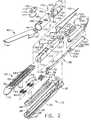
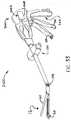
- FIG. 1is a perspective view of an aspect of a surgical cutting and fastening instrument
- FIG. 2is an exploded assembly view of an aspect of an end effector arrangement that may be employed in connection with various aspects of the surgical cutting and fastening instrument;
- FIG. 3is a top view of the end effector of FIGS. 1 and 2 with the anvil portion removed therefrom and the closure tube assembly illustrated in phantom lines;
- FIG. 4is a cross-sectional side elevational view of the end effector arrangement of FIG. 3 with the anvil portion attached thereto and shown in an open position;
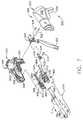
- FIG. 5is a cross-sectional top view of a portion of an articulation control that may be employed with various aspects of the surgical cutting and fastening instrument;
- FIG. 6is a top cross-sectional view illustrating the articulation of the end effector depicted in FIG. 1 ;
- FIG. 7is an exploded assembly view illustrating an aspect of a closure tube assembly and shuttle arrangement supported within the handle assembly with other components housed within the housing assembly being omitted for clarity;
- FIG. 8is a cross-sectional view of a housing assembly arrangement of various aspects of the surgical cutting and fastening instrument
- FIG. 8Ais a partial cross-sectional view of a portion of a closure trigger locking system that may be employed in connection with various aspects of the surgical cutting and fastening instrument;
- FIG. 8Bis a cross-sectional view of another handle assembly aspect of the surgical cutting and fastening instrument wherein the source of pressurized gas is external to the handle assembly;
- FIG. 8Cis a cross-sectional view of another handle assembly aspect of the surgical cutting and fastening instrument.
- FIG. 9is another cross-sectional view of the handle assembly of FIG. 8 ;
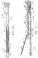
- FIG. 10is a side view of a knife bar arrangement and a firing drive member that comprises a two stage cylinder assembly of various aspects of the surgical cutting and fastening instrument with the cylinder assembly shown in cross-section;
- FIG. 11is another side view of the knife bar and two stage cylinder arrangements depicted in FIG. 10 with the knife bar in the extended position;
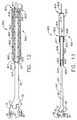
- FIG. 12is a side view of another knife bar and firing drive member arrangement of the surgical cutting and fastening instrument with the knife bar being retracted into a cylinder assembly shown in cross-section;
- FIG. 13is another side view of the knife bar and cylinder arrangements depicted in FIG. 12 with the knife bar in the extended position;
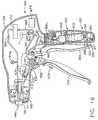
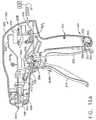
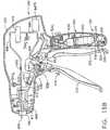
- FIG. 14is a top view of an end effector and spine assembly arrangement housing the cylinder and knife bar arrangements depicted in FIGS. 12 and 13 ;
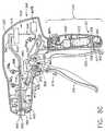
- FIG. 15is a cross-sectional side elevational view of the end effector and spine assembly arrangement depicted in FIG. 14 with the anvil portion attached thereto and in the open position;
- FIG. 16is a cross-sectional view of a handle assembly that may be used in connection with the aspect depicted in FIGS. 12-15 ;
- FIG. 16Ais a cross-sectional view of another handle assembly that may be used in connection with the aspect depicted in FIGS. 12-15 wherein the source of pressurized gas is external to the handle assembly;
- FIG. 16Bis a cross-sectional view of another handle assembly aspect of the surgical cutting and fastening instrument.
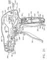
- FIG. 17is a top view of another knife bar and spine assembly arrangement that supports another firing drive member in the form of a bellows assembly of another aspect of the surgical cutting and fastening instrument;
- FIG. 18is a cross-sectional side elevational view of the end effector and spine assembly arrangements of the aspect depicted in FIG. 17 ;
- FIG. 19is a partial cross-sectional assembly view of a bellows assembly of the aspects depicted in FIGS. 17 and 18 ;
- FIG. 20is an enlarged view of a portion of the bellows assembly of FIG. 19 ;
- FIG. 21is a cross-sectional view of a handle assembly aspect that may be used in connection with the aspects depicted in FIGS. 17-20 ;
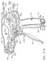
- FIG. 21Ais a cross-sectional view of another handle assembly aspect that may be used in connection with the aspects of FIGS. 17-20 wherein the source of pressurized gas is external to the handle assembly;
- FIG. 21Bis a cross-sectional view of another handle assembly aspect of the surgical cutting and fastening instrument.
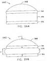
- FIGS. 22A and 22Billustrate various aspects of a proportional sensor.
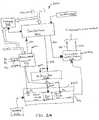
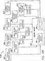
- FIG. 23is a schematic diagram of one aspect of an electrical circuit of the instrument according to various aspects thereof.
- FIG. 24illustrates one aspect of an electrically controlled pneumatic system.
- FIG. 25illustrates various aspects of a surgical instrument with the capability to record instrument conditions at one or more times during use.
- FIG. 26illustrates one aspect of a closure trigger sensor.
- FIG. 27illustrates one aspect of an anvil closure sensor.
- FIG. 28illustrates one aspect of a knife position sensor that is suitable for use with the pneumatically actuated piston bar portion protruding from the knife assembly.
- FIGS. 29 and 30illustrate one aspect of a cartridge present sensor.
- FIGS. 31A and 31Billustrate one aspect of a process flow for operating aspects of a surgical instrument configured as an endocutter and having the capability to record instrument conditions according to various aspects.
- FIG. 32shows one aspect of a memory map from the memory device.
- FIG. 33illustrates various aspects of a surgical instrument.
- FIG. 34illustrates a schematic of one aspect of a surgical instrument comprising a plurality of sensors.
- FIG. 35illustrates one aspect of an indicator to provide audible and visual feedback.
- FIG. 36illustrates one aspect of a status module.
- FIG. 37illustrates one aspect of a status module.
- a pneumatically powered instrumentcomprises an integrated pneumatic actuation system and electrical control, recording, and/or feedback elements.
- a pneumatic actuation systemis combined with an electrical control system to pneumatically actuate the instrument and electrically control the flow rate in the pneumatic system.
- An actuatormay be employed to electrically control the pressurization of the pneumatic system.
- the control systemreceives pressurized gas from a source and produces an electrical output to actuate an element of the instrument employing at least one electrical component or element.
- the control systemmay be employed to control elements of a surgical cutting and fastening device.
- the cutting and fastening elementsare pneumatically operable by a controller.
- the actuation of a pneumatic cylindermay be controlled with a pressurized gas and a controller.
- the controllercontrols the rate at which the pressurized gas is released within the pneumatic system.
- the controllermay be employed to control one or more flow control elements such as solenoids, piezoelectric actuators, or electric motors. These flow control elements may be employed to open and close valves and other closure mechanisms to control the rate of discharge of the pressurized gas into the actuation cylinder. Additional flow control elements may be employed to release the pressurized gas at a variable rate. The aspects are not limited in this context.
- a pneumatically powered instrumentcomprises electrical recording capabilities.
- the instrumentmay comprise an information recording system including, for example, a battery, circuit element, and memory device integrated with the pneumatically powered instrument.
- the information recording systemmay be employed to record information associated with the instrument.
- the instrumentmay comprise a switch, trigger, actuator, or other elements or techniques to selectively discharge a pressurized pneumatic gas to actuate the instrument.
- the instrumentmay further comprise one or more sensors to enhance the information gathered by the recording system. Various sensors may be employed to provide information to the information recording system.
- the sensorsinclude sensors to measure and/or record the number of actuations and reprocessings, the force to actuate or close an end effector of the instrument, the clamping force of the end effector, the pressure exerted on tissue, whether a cartridge is loaded in the instrument, the status of the cartridge, the lockout status of the instrument, the pressure in the pneumatic actuation cylinder, whether the surgical instrument is ready-to-fire, and so forth.
- the aspectsare not limited in this context.
- a pneumatically powered instrumentcomprises electrical feedback capabilities.
- the pneumatically powered instrumentmay be integrated with a feedback module.
- the feedback modulemay be self contained and adapted to connect to a plurality of contacts disposed throughout the instrument, an electrical circuit element, and a plurality of indicators.
- the feedback system, indicators, sensors, and controlsmay be electrically powered.
- the instrumentmay comprise pneumatically powered or power-assisted surgical cutting and fastening device. The aspects are not limited in this context.
- FIG. 1depicts a surgical stapling and cutting instrument 10 that is capable of practicing several unique benefits.
- the aspect illustrated in FIG. 1includes a handle assembly 300, an elongate shaft assembly 100, and an end effector 12 that is connected to the elongate shaft assembly 100.
- Various aspects of the surgical apparatusmay include an end effector that is pivotally attached to the elongate shaft assembly 100 and pivotally driven by bending cables or bands such as those disclosed in U.S. Patent Application Serial No. 11/329,020, filed January 10, 2006 , entitled "SURGICAL INSTRUMENT HAVING AN ARTICULATING END EFFECTOR".
- the handle assembly 300 of the instrument 10may include a closure trigger 302 and a firing trigger 310. It will be appreciated that instruments having end effectors directed to different surgical tasks may have different numbers or types of triggers or other suitable controls for operating an end effector.
- the end effector 12is shown separated from the handle assembly 300 by the preferably elongate shaft assembly 100. A clinician may articulate the end effector 12 relative to the shaft assembly 100 by utilizing an articulation control 200.
- multiple sensorsmay be coupled to elements in the hand assembly 300, the elongate shaft assembly 100, and/or the end effector 12 to measure and control various functions of the instrument 10, record the status of various components of the instrument, and provide the clinician or user with feedback indications.
- the instrument 10comprises a plurality of sensors), wherein the plurality of sensors includes, for example, a closure trigger sensor, an anvil closure sensor, an anvil closure load sensor, a knife position sensor, a cartridge present sensor, a cartridge condition sensor, a firing trigger sensor, and a valve actuation sensor, or any combination thereof.
- Other sensorsmay comprise an articulation angle sensor, an anvil position sensor, a firing force sensor, a lockout condition sensor, a pneumatic pressure sensor, a flow rate sensor, or any combination thereof. Each sensor may be in electrical communication with a different contact positioned proximate the exterior of the surgical instrument 10. Sensors may be coupled to the closure trigger 302 and the firing trigger 310 to detect their operation. Sensors may be employed to measure the anvil 40 closure and the closure load on the anvil 40. Other sensors may be employed to measure the position of the knife assembly 30 ( FIG. 2 ), the presence of the staple cartridge 50 ( FIG. 2 ) and/or the status of the staple cartridge 50 (e.g., spent or un-spent).
- sensorsmay be employed throughout the instrument 10 to determine the number of actuations of instrument 10, the pressure in the pneumatic system, pressure of the pneumatic cylinder or actuation cylinder, variable rate sensors to activate valve actuators and the like.
- the aspectare not limited in this context.
- the sensor output signals S 1 to S nare provided to an electronic control module 603 located in the handle assembly, for example.
- the electronic control module 603comprises a controller, a memory device, a battery, a measurement circuit, and/or an actuator to control a closure mechanism portion of an electrically controlled variable rate pneumatic valve as described hereinbelow.
- the aspectare not limited in this context.
- proximalis used to denote a perspective of a clinician who is behind the handle assembly 300 who places the end effector 12 distal, or away from him or herself.
- pressurized gasrefers to any gas suitable for use in pneumatically powered systems employed in a sterile environment.
- mediumsinclude compressed air, carbon dioxide (CO2), Nitrogen, Oxygen, Argon, Helium, Sodium Hydride, Propane, Isobutane, Butane Chlorofluorocarbons, Dimethyl ether.
- HFAHyrdofluoroalkanes
- the term "fluidically coupled”means that the elements are coupled together with an appropriate line or other means to permit the passage of pressurized gas therebetween.
- lineas used herein, the term "line” as used in “supply line” or “return line” refers to an appropriate passage formed from rigid or flexible conduit, pipe and/or tubing, for transporting pressurized gas from one component to another.
- pneumatic signalor “pneumatic drive signal” refer to the flow of gas from a source of pressurized gas to one or more components that are fluidically coupled to the source of pressurized gas or the flow of gas between components that are fluidically coupled together.
- FIG. 2illustrates an exploded assembly view of one type of pneumatically actuated and electrically controlled tool assembly or end effector that may be employed in various aspects of the surgical instrument 10.
- the pneumatically operated actuated and electrically controlled assembly 12 shown in FIGS. 1-4is configured to act as an endocutter.
- various unique and novel drive arrangements of aspects of the present inventioncould also be conceivably employed to drive other end effectors configured to perform other surgical tasks and thus requiring the removal, modification, or addition of components from what is shown in the Figures.
- the end effectors 12 shown in FIGS. 1-4may be customized for specific surgical applications.
- FIG. 2One type of end effector that may be employed with various aspects of the surgical instrument 10 is depicted in FIG. 2 .
- the end effector 12employs an E-beam firing mechanism ("knife assembly") 30 that, in addition to cutting tissue and firing staples located in a staple cylinder seated therein, advantageously controls the spacing of an anvil 40 portion of the end effector 12 relative to the staple cylinder.
- E-beam firing mechanismsare described in U.S. Patent No. 6,978,921 , entitled Surgical Stapling Instrument Incorporating An E-Beam Firing Mechanism to Shelton, IV. et al..
- knife and firing mechanism configurationsmay be advantageously employed without departing from the overall scope of the aspects.
- firing mechanismrefers to the portion or portions of the pneumatically actuated and electrically controlled tool and/or end effector that move from an unactuated position wherein the firing mechanism may be essentially at rest to an actuated or end position wherein that portion or portions have been moved or repositioned to a final position wherein such movement thereof resulted in the tool completing one or more actions in response to the application of at least one firing motion thereto.
- the firing mechanismmay comprise, for example: (i) components that are completely supported by the pneumatically actuated and electrically controlled tool and interface with components in the surgical apparatus; (ii) a combination of components that are located in the pneumatically powered tool and in the surgical apparatus; or (ii) components that are supported by the surgical apparatus and are movable into and out of the pneumatically actuated and electrically controlled tool.
- firing strokerefers to the actual movement of the firing mechanism from the unactuated position to the actuated position.
- retract strokerefers to the return movement of the firing mechanism from the actuated position to the unactuated position.
- the end effector 12includes a distal member that, in various non-limiting embodiments, comprise an elongate channel 20 that has a pivotally translatable anvil 40 attached thereto.
- the elongate channel 20is configured to receive and support a staple cartridge 50 that is responsive to the knife assembly 30 to drive staples 70 into forming contact with the anvil 40.
- a staple cartridge consistent with aspects of the present inventionmay be permanently affixed or integral to the elongate channel 20.
- the firing mechanism or knife assembly 30includes vertically spaced pins that control the spacing of the end effector 12 during firing.
- upper pins 32are staged to enter an anvil pocket 42 near the pivot between the anvil 40 and elongate channel 20. See FIG. 4 .
- the upper pins 32advance distally within a longitudinal anvil slot 44 extending distally through anvil 40. Any minor upward deflection in the anvil 40 is overcome by a downward force imparted by the upper pins 32.
- Knife assembly 30also includes a knife bar cap 34 that upwardly engages a channel slot 23 formed in the elongate channel 20, thereby cooperating with the upper pins 32 to draw the anvil 40 and the elongate channel 20 slightly closer together in the event of excess tissue clamped therebetween.
- the knife assembly 30may advantageously include middle pins 36 that pass through a firing drive slot (not shown) formed in a lower surface of the cartridge 50 and an upward surface of the elongate channel 20, thereby driving the staples 70 therein as described below.
- the middle pins 36by sliding against the elongate channel 20, advantageously resist any tendency for the end effector 12 to be pinched shut at its distal end.
- the unique and novel aspects of various aspects of the present inventionmay be attained through use of other knife assembly arrangements.
- a distally presented cutting edge 38 between the upper and middle pins 32, 36 on the knife assembly 30traverses through a proximally presented, vertical slot 54 in the cartridge 50 to sever clamped tissue.
- the affirmative positioning of the knife assembly 30 with regard to the elongate channel 20 and anvil 40assure that an effective cut is performed.
- the lower surface of the anvil 40may be provided with a plurality of staple forming pockets therein (not shown) that are arrayed to correspond to a plurality of staple apertures 58 in an upper surface 56 of the staple cartridge 50 when the staple cartridge 50 is received within the elongate channel.
- the staple cartridge 50may be snap fit into the elongate channel 20.
- extension features 60, 62 of the staple cartridge 50frictionally and releasably engage recesses 24, 26, respectively of the elongate channel 20.
- the staple cartridge 50comprises a cartridge body 51, a wedge sled 64, staple drivers 66, staples 70, and a cartridge tray 68.
- the cartridge tray 68holds the wedge sled 64, staple drivers 66, and staples 70 inside the cartridge body 51.
- the elongate channel 20is coupled to the handle assembly 300 by the elongate shaft assembly 100 which includes a distal spine or frame section 110 and a proximal spine or frame section 130.
- the elongate channel 20has proximally placed attachment cavities 22 that each receives a corresponding channel anchoring member 114 formed on the distal end of the distal spine section 110.
- the elongate channel 20also has anvil cam slots 28 that pivotally receive a corresponding anvil pivot 43 on the anvil 40.
- a closure sleeve assembly 170is received over the spine assembly 102 and includes distal closure tube segment 180 and a proximal closure tube segment 190. As will be discussed below, axial movement of the closure sleeve assembly 170 relative to the spine assembly 102 causes the anvil 40 to pivot relative to the elongate channel 20.
- a locking spring 112is mounted in the distal spine segment 110 as a lockout for the knife assembly 30.
- Distal and proximal square apertures 111, 113are formed on top of the distal spine segment 110 to define a clip bar 115 therebetween that receives a top arm 116 of the locking spring 112 whose lower, distally extended arm 118 asserts a downward force on a distal end of a cylinder assembly 501 supporting the piston bar portion 35 protruding from the knife assembly 30 as will be discussed in further detail below. It will be appreciated that various aspects may include other types of lockouts or no lockouts at all.
- the end effector 12may be articulated relative to the proximal closure tube segment 190 (and handle assembly 300) by a collection of cables or bands that are bent to pull the end effector 12 about a pivot 104.
- a collection of cables or bandsthat are bent to pull the end effector 12 about a pivot 104.
- the proximal end of the distal spine segment 110has a boss 122 thereon.
- the distal end of the proximal spine segment 130is provided with a tang 134 that has an aperture 136 therethrough.
- the proximal spine segment 130is positioned relative to the distal spine segment 110 such that the aperture 136 is coaxially aligned with an aperture 124 in boss 122 to enable a pivot pin 138 to extend therethrough. See FIG. 4 .
- Such arrangementwhen assembled, permits the end effector 12 to pivot relative to the proximal spine segment 130 about pivot axis A-A.
- band 150, 160may extend distally toward the articulation pivot 104 as shown in FIGS. 2 and 3 .
- Band 150may extend through the proximal closure tube segment 190 along its left side where it is routed around band member 160 and across to the right side of the proximal closure tube segment 190.
- the band 150may be mechanically coupled to boss 122, for example, at connection point 123.
- band 160may extend through the proximal closure tube segment 190 along its right side where it is routed around band member 150 and across to the left side of the proximal closure tube segment 190.
- band 160may be mechanically coupled to the boss 122 at connection point 125.
- FIG. 3is a top view of the end effector and spine assembly 102 with the closure tube assembly 100 depicted in phantom lines.
- FIG. 4is a partial cross-sectional side view of the same portion of the instrument 10.
- bands 150 and 160are shown offset from one another to prevent interference in movement according to one non-limiting aspect
- band 150is shown at a lower position than band 160.
- the vertical positioning of bands 150 and 160may be reversed.
- the band member 150extends around a pin 140 in the tang portion 134 of the proximal frame segment 130.
- band 160extends around pin 142 in the tang portion 134 of the proximal frame segment 130.
- Band portions 150 and 160may extend from the boss 122 and along the proximal closure tube segment 190 to the articulation control 200, shown in FIG. 5 .
- the articulation control 200may include an articulation slide 202, a frame 204 and an enclosure 206. Band portions 150, 160 may pass through the articulation slide 202 by way of slot 208 or other aperture, although it will be appreciated that the band portions 150, 160 may be coupled to the slide 202 by any suitable means.
- the articulation slide 202may be one piece, as shown in FIG. 5 , or may in one non-limiting aspect, include two pieces with an interface between the two pieces defining the slot 208. In one non-limiting aspect, the articulation slide 202 may include multiple slots, for example, with each slot corresponding to one of band portions 150, 160.
- Enclosure 206may cover the various components of the control 200 to prevent debris from entering.
- band portions 150, 160may be anchored to the frame 204 at connection points 210, 212 proximally located from the slot 208.
- the non-limiting aspect of FIG. 5shows that the band portions 150, 160 are pre-bent from connection points 210, 212 to the slot 208 located near the longitudinal axis of the proximal closure tube segment 190. It will be appreciated that band portions 150, 160 may be anchored anywhere in the instrument 10 located proximally from the slot 208, including the handle assembly 300.
- the aspect of FIG. 2may have an unarticulated position as shown in FIG. 3 .
- the articulation control 200 and bands 150, 160are shown in a centered position roughly at the longitudinal axis of the shaft assembly 100. Accordingly, the end effector 12 is in a neutral or unarticulated position.
- the articulation control 200is shown with the articulation slide 202 pushed through the articulation frame to the right side of the shaft assembly 100. Accordingly, bands 150, 160 are bent toward the right side of the shaft assembly 100. It can be seen that the bending of band 150 to the right exerts a laterally directed force on the boss 122 that is offset from the boss's 122 pivot point.
- This offset forcecauses the boss 122 to rotate about articulation pivot 104, in turn causing the end effector 12 to pivot to the right as shown.
- pushing the articulation slide 202 to the left side of the shaft assembly 100may exert a laterally directed force on bands 150, 160, bending both bands 150, 160 toward the left side of the shaft assembly 100.
- the bending of band 160then exerts a laterally directed force on boss 122, which as above, is offset from the boss's 122 pivot point. This, in turn, causes the boss 122 to rotate about the articulation pivot causing the end effector 12 to pivot to the left.
- the shaft assembly 100is comprised of a closure tube assembly 170 that is received on the spine assembly 102. See FIG. 2 .
- the closure tube assembly 170comprises a distal closure tube segment 180 and a proximal closure tube segment 190.
- the distal closure tube segment 180 and the proximal closure tube segment 190may be fabricated from a polymer or other suitable material.
- the proximal closure tube segment 190is hollow and has an axial passage 191 extending therethrough that is sized to receive a portion of the spine assembly 102 therein.
- a double pivot closure joint 172is employed. It will be appreciated that the invention is not limited to a double pivot closure joint design and may include any suitable closure tube or sleeve, or no closure tube or sleeve at all.
- the distal closure tube segment 180has upper and lower proximally projecting tangs 182, 184.
- the distal closure tube segment 180further includes a horseshoe aperture 185 and tab 186 for engaging the anvil open/closing tab 46 on the anvil 40 to cause the anvil 40 to pivot between open and closed positions as will be discussed in further detail below.
- the proximal closure tube segment 190is similarly provided with a distally extending upper tang 192 and a distally extending lower tang 194.
- An upper double pivot link 174includes upwardly projecting distal and proximal pivot pins 175, 176 that engage respectively an upper distal pin hole 183 in the upper proximally projecting tang 182 and an upper proximal pin hole 193 in the upper distally projecting tang 192.
- the joint arrangementfurther includes a lower double pivot link 177 that has downwardly projecting distal and proximal pivot pins 178, 179 (not shown in FIG. 2 , but see FIG. 4 ) that engage respectively a lower distal pin hole 187 in the lower proximally projecting tang 184 and a lower proximal pin hole 195 in the lower distally projecting tang 194.
- the closure tube assembly 170is translated distally to close the anvil 40, for example, in response to the actuation of the closure trigger 302.
- the anvil 40is closed by distally translating the closure tube assembly 170 on the spine assembly 102, causing the back of the horseshoe aperture 185 to strike the open/closing tab 46 on the anvil 40 and cause it to pivot to the closed position.
- the closure tube assembly 170is axially moved in the proximal direction on the spine assembly 102 causing the tab 186 to contact and push against the open/closing tab 46 to pivot the anvil 40 to the opened position.
- a sensormay be located in the closure tube assembly 170 to measure the force asserted on the horseshoe aperture 185 to strike the open/closing tab 46 on the anvil 40 to cause it to pivot to the closed position and to maintain it in the closed position.
- FIG. 7illustrates an exploded assembly view of a non-limiting handle assembly 300 of various aspects of the surgical apparatus.
- the handle assemblyhas a "pistol grip" configuration and is formed from a right hand case member 320 and a left handed case member 330 that are molded or otherwise fabricated from a polymer or other suitable material and are designed to mate together.
- Such case members 320 and 330may be attached together by snap features, pegs and sockets molded or otherwise formed therein by adhesive, screws, bolts and/or clips.
- the upper portion 322 of the right hand case member 320mates with a corresponding upper portion 323 of the left hand case member 330 to form a primary housing portion designated as 340.
- the lower grip portion 324 of the right hand case member 320mates with the lower grip portion 334 of the left hand case member to form a grip portion generally designated as 342.
- the entire grip portion 342is integral with the primary housing portion 340.
- Such arrangementmay be particularly well-suited for applications wherein a source of pressurized gas is permanently installed within the grip portion 342.
- Such arrangementis also suited for use with sources of pressurized gas that are external to the handle assembly 300 and plugged into the control components housed therein through a port or ports in the housing assembly.
- the grip portion 342is detachable from the primary housing portion 340. As will be appreciated as the present Detailed Description proceeds, such arrangement provides a myriad of benefits and advantages. Those of ordinary skill in the art will readily appreciate, however, that the handle assembly 300 may be provided in a variety of different shapes and sizes.
- FIG. 7only illustrates the components employed to control the axial movement of the closure tube assembly 170 which ultimately controls the opening and closing of the anvil 40.
- a closure shuttle 400that is coupled to the closure trigger 302 by a linkage assembly 430 is supported within the primary housing portion 340.
- Closure shuttle 400may also be fabricated in two pieces 402, 404 that are molded or otherwise fabricated from a polymer or other suitable material and are designed to mate together.
- the right hand portion 402may be provided with fastener posts 403 that are designed to be received within corresponding sockets (not shown) in the left hand portion 404.
- the right and left hand portions 402, 404may be otherwise retained together by snap members and/or adhesive and/or bolts, screws and/or clips.
- a retention groove 196is provided in the proximal end of the proximal closure tube segment 190.
- the right hand portion 402 of the closure shuttle 400has a right retention flange segment 405 that is adapted to cooperate with a left retention flange segment (not shown) on the left hand portion 404 of the closure shuttle 400 to form a retention flange assembly that extends into the retention groove 196 in the proximal closure tube segment 190.
- a right spine assembly retention peg 326protrudes inward from the right hand case member 320. Such peg 326 protrudes into an elongated slot or window 406 in the right hand portion 402 of the closure shuttle 400.
- a similar closure shuttle retention pegprotrudes inward from the left hand case member 330 to be received in another window or slot 408 provided in the left hand side portion 404 of the closure shuttle 400.
- the retention pegsserve to non-movably affix the proximal end 133 of the proximal spine segment 130 (not shown in FIG. 7 ) to the handle assembly 300 while permitting the closure shuttle 400 to move axially relative thereto.
- the retention pegsmay be mechanically attached to the proximal end of the proximal spine segment 130 by, for example, bolts, screws, adhesive, and/or snap features.
- the closure shuttle 400is provided with laterally extending guide rails 410, 411. Rail 410 is configured to be slidably received within rail guide 328 the right hand case member 320 and rail 411 is configured to be slidably received within a rail guide (not shown) in left hand case member 330.
- Axial movement of the closure shuttle 400 and closure tube assembly 170 in the distal directionis created by moving the closure trigger 302 toward the grip portion 342 of the handle assembly 300 and axial movement of the closure shuttle 400 in the proximal direction (arrow “D") is created by moving the closure trigger 302 away from the grip portion 342.
- the closure shuttle 400is provided with a connector tab 412 that facilitates the attachment of the closure linkage assembly 430 thereto. See FIGS. 8 and 9 .
- the closure linkage assembly 430includes a yoke portion 432 that is pivotally pinned to the connector tab 412 by a pin 414.
- the closure linkage assembly 430further has a closure arm 434 that is pivotally pinned to a yoke assembly 304 formed on the closure trigger 302 by a closure pin 436 as illustrated in FIG. 7 .
- the closure trigger 302is pivotally mounted within the handle assembly 300 by a pivot pin 306 that extends between the right hand case member 320 and the left hand case member 330.
- the clinicianWhen the clinician desires to close the anvil 40 to clamp tissue within the end effector 12, the clinician draws the closure trigger 302 toward the grip portion 342. As the clinician draws the closure trigger 302 toward the grip portion 342, the closure linkage assembly 430 moves the closure shuttle 400 in the distal "C" direction until the closure linkage assembly 430 moves into the locked position illustrated in FIG. 8 . When in that position, the linkage assembly 430 will tend to retain the closure shuttle 400 in that locked position.
- closure tube assembly 170is moved distally on the spine assembly 102 causing the closure/opening tab 46 on the anvil 40 to be contacted by the proximal end of the horseshoe aperture 185 in the distal closure tube segment 180 to thereby pivot the anvil 40 to the closed (clamped) position.
- the closure trigger 302may be provided with a releasable locking mechanism 301 that is adapted to engage the grip portion 342 and releasably retain the closure trigger 302 in the locked position.
- Other locking devicesalso may be used to releasably retain the closure shuttle 400 in the locked position.
- the closure trigger 302includes a flexible longitudinal arm 303 that includes a lateral pin 305 extending therefrom.
- the arm 303 and pin 305may be made from molded plastic, for example.
- the pistol grip portion 342 of the handle assembly 300includes an opening 350 with a laterally extending wedge 352 disposed therein.
- the pin 305engages the wedge 352, and the pin 305 is forced downward (i.e., the arm 303 is rotated CW) by the lower surface 354 of the wedge 352.
- the pin 305fully passes the lower surface 354, the CW force on the arm 303 is removed, and the pin 305 is rotated CCW such that the pin 305 comes to rest in a notch 356 behind the wedge 352 thereby locking the closure trigger 302.
- the pin 305is further held in place in the locked position by a flexible stop 358 extending from the wedge 352.
- the operatormay further squeeze the closure trigger 302, causing the pin 305 to engage a sloped back wall 359 of the opening 350, forcing the pin 305 upward past the flexible stop 358.
- the pin 305is then free to travel out an upper channel in the opening 360 such that the closure trigger 302 is no longer locked to the pistol grip portion 342.
- the knife assembly 30may have a substantially rigid piston bar portion 35 protruding therefrom or otherwise attached thereto that is part of a drive member 500 that is operably supported by the distal spine segment 110 and configured to apply at least two actuation motions (e.g., firing motion and retraction motion) to the knife assembly 30.
- the drive member 500comprises a two stage pneumatically-actuated cylinder assembly 501.
- the knife assembly 30may comprise a unitary component or it may be provided in multiple pieces to facilitate easier assembly of the instrument 10. For example, as shown in FIGS.
- the knife bar assembly 30comprises a distal portion 31 that contains the upper pins 32, the cap 34, the middle pins 36 and the knife 38.
- Distal portion 31may be provided with an aperture 33 therein sized to receive a protrusion 37 provided on the distal end of the piston bar portion 35.
- the protrusion 37may be frictionally received within the aperture 33 and/or retained therein by adhesive and/or welding.
- the cylinder assembly 501comprises a first cylinder housing 510 that has a first closed proximal end 512 and a first open distal end 514 that opens into a first axial passage 516 within the first cylinder housing 510.
- the cylinder assembly 501also comprises a second cylinder housing 520 that has a second proximal end 522 and a second open distal end 524 that opens into a second axial passage 526.
- the second closed proximal end 522has a first piston head 528 formed thereon that is sized relative to the first axial passage 516 to create a substantially airtight sliding seal with the first wall 511 of the first cylinder housing 510 to define a first cylinder area 515 between the distal side of the first proximal end 512 and the proximal side of the first piston head 528.
- the first distal end 514 of the first cylinder housing 510further has an inwardly extending first flange 517 formed thereon for establishing a substantially airtight sliding seal with the outer wall surface of the second cylinder housing 520 to define a second cylinder area 518 between the proximal side of the first flange 517 and the distal side of the first piston head 528.
- a first passage 527is provided through the first piston head 528.
- the proximal end of the piston bar 35extends through the second open distal end 524 of the second cylinder housing 520 and into second axial passage 526.
- a second piston head 530is formed on or otherwise attached to the proximal end of the piston bar 35.
- the second piston head 530is sized relative to the second axial passage 526 to create a substantially airtight sliding seal with a second wall 521 of the second cylinder housing 520 to define a third cylinder area 532.
- the second distal end 524 of the second cylinder housing 520further has an inwardly extending second flange 525 formed thereon for establishing a substantially airtight sliding seal with the piston bar 35 to define a fourth cylinder area 534 between the proximal side of the second flange 525 and the distal side of the second piston head 530.
- the cylinder assembly 501is mounted within the distal spine segment 110.
- a pair of trunions 519are provided on the proximal end of the first cylinder housing 510.
- the trunions 519are received within trunion bores 119 in the distal spine segment 110 to enable the cylinder assembly 501 to pivot within the distal spine segment 110 about a pivot axis B-B. See FIG. 3 .
- a first supply line or supply conduit 540extends from a directional control valve 610 in the handle assembly 300 ( FIGS.
- a pressure sensormay be fluidically coupled to the first supply line 540 to measure or sense pressure (P) in the first supply line 540.
- the pressure sensorprovides an electrical feedback signal to the electronic control module 603 that is proportional to the pressure in the first supply line 540.
- a second supply line 542extends from the directional control valve 610 through the proximal closure tube segment 190 and is connected to the first cylinder housing 510 adjacent the distal end 514 thereof to supply pressurized gas into the second cylinder area 518 through a second port 529.
- a pressure sensormay be fluidically coupled to the second supply line 542 to measure or sense pressure (P) in the second supply line 542.
- the pressure sensorprovides an electrical feedback signal to the electronic control module 603 that is proportional to the pressure in the second supply line 542.
- Other pressure sensorsmay be fluidically coupled throughout the pneumatic system.
- pressure sensorsmay be fluidically coupled to the respective first and second pressure supply ports 513, 529 to measure the pressure within the respective first and second cylinder areas 515, 518. In this manner, the pressure within the two stage cylinder assembly 501 may be measured and provided as a feedback signal to the electronic control module 603.
- the supply lines 540 and 542are coupled to an electrically controlled directional valve 610 which is part of an actuator system 600 housed within the handle housing 350.
- the actuator system 600comprises an actuation trigger 670, a directional valve 610, and an electrically controlled variable flow rate pneumatic valve 660. These elements are coupled to the electronic control module 603.
- the electronic control module 603receives feedback signals from various sensors distributed throughout the instrument 10.
- the electronic control module 603provides control signals to various control elements distributed throughout the instrument 10 based on the feedback signals.
- the electronic control module 603comprises a controller 702, a memory device 703, a battery 704, a measurement circuit 732, and/or an actuator 706 to control a closure mechanism 730 portion of the electrically controlled variable flow rate pneumatic valve 660. See FIG 26 .
- the actuator system 600may be in communication with a status module 2408 (described below with reference to FIGS. 33-37 ).
- the directional valve 610may be electrically controlled by the electronic control module 603. In other aspects, the directional valve may be shifted manually between forward (extend) and reverse (retract) positions by a selector switch 612 or push buttons that are accessible through the handle housing 350.
- the selector switch 612 or the appropriate buttonmay be implemented in electrical form to generate a signal indicative of a desired state of the directional valve 610.
- the signalmay be coupled to the controller 702, which generates a valve direction control signal to control the directional valve 610.
- a removable source 620 of pressurized gasis employed.
- such source of pressurized gascomprises a cylinder 622 that may be rechargeable with a preferred pressurized gas.
- the handle assembly 300may be provided with a port 616 for supplying pressurized gas from an external source 618 of pressurized gas.
- the instrument 10could be coupled to the facility's compressed air supply 618 through a flexible supply line 617. See FIG. 8B .
- a pressure sensormay be fluidically coupled to an outlet port of the removable source 622 or a facility's compressed air supply 618 to measure or sense the pressure in an input supply line 650. The pressure sensor provides an electrical feedback signal to the electronic control module 603 that is proportional to the pressure in the input supply line 650.
- variable flow rate pneumatic valve 660is controlled by the controller 702.
- the variable flow rate pneumatic valve 660is coupled to a valve actuation sensor 662 that is activated by an activation trigger 670.
- the valve actuation sensor 662may be a digital or analog sensor that is coupled to the controller 702.
- the valve actuation sensor 662is a proportional sensor that provides an electrical signal that is proportional to the desired flow rate through the electrically controlled variable flow rate pneumatic valve 660.
- the valve actuation sensor 662detects the movement of the activation trigger 670, it sends an electrical signal to the controller 702 that is proportional to the desired flow rate of the pressurized gas flowing from the cylinder 622 into a supply line 680 to the first or second supply lines 540, 542.
- the controller 702adjusts a flow control element within the variable flow rate pneumatic valve 660 to produce the desired flow rate of the pressurized gas.
- a pressure sensormay be fluidically coupled to the supply line 680 to measure or sense the pressure in the supply line 680.
- variable flow rate actuation assemblyat least comprises the variable flow rate pneumatic valve 660, the activation trigger 670, the controller 702, the battery 704, and the actuator 706, and their respective equivalent structures.
- the valve actuation sensor 662(see FIGS. 22A, 22B ) is in communication with the activation trigger 670 to detect when the activation trigger 670 has been drawn in (or "closed") toward the lower grip portion 324 of the handle by the operator to thereby pneumatically actuate the cutting/stapling operation by the end effector 12 in an electrically controlled manner.
- the valve actuation sensor 662may be a proportional sensor such as, for example, a rheostat or variable resistor. When the activation trigger 670 is drawn in, the valve actuation sensor 662 detects the movement, and sends an electrical signal to the controller 702 and or the memory device 703 that is indicative of the desired pressure or flow rate through the pneumatic system.
- the controller 702sends an electrical actuation signal to the actuator 706 to control the flow rate through the variable flow rate pneumatic valve 660.
- the valve actuation sensor 662is a variable resistor or the like
- the actuation signalmay be generally proportional to the amount of movement of the actuation trigger 670. That is, if the operator only draws or closes the actuation trigger 670 in a little bit, the actuation signal and hence the flow rate is relatively low.
- the actuation trigger 670is fully drawn in (or in the fully closed position), the actuation signal and hence the flow rate is at its maximum. In other words, the harder the user pulls on the actuation trigger 670, the greater the actuation signal causing greater flow rate through the variable flow rate pneumatic valve 660.
- the actuator 706may comprise any suitable type of actuation mechanism comprising electric motors, suitable gear reductions, a pneumatic actuator, solenoids, piezo-actuators, as well as any other suitable device capable of transforming a source of potential energy, such as electricity or compressed air, into physical displacement suitable for driving a closure mechanism 730 ( FIG. 24 ).
- FIGS. 22A and 22illustrate various aspects of a proportional sensor.
- FIGS. 22A and 22Billustrate two states of a proportional sensor that may be used as the valve actuation sensor 662 according to various aspects of the instrument.
- the valve actuation sensor 662may include a face portion 708, a first electrode (A) 710, a second electrode (B) 712, and a compressible dielectric material 714 between the electrodes 710, 712, such as, for example, an electroactive polymer (EAP).
- EAPelectroactive polymer
- the valve actuation sensor 662may be positioned such that the face portion 708 contacts the actuation trigger 670 when retracted.
- the dielectric material 714is compressed, as shown in Figure 22B , such that the electrodes 710, 712 are closer together. Since the distance "b" between the electrodes 710, 712 is directly related to the impedance between the electrodes 710, 712, the greater the distance the more impedance, and the closer the distance the less impedance. In that way, the amount that the dielectric 714 is compressed due to retraction of the actuation trigger 670 (denoted as force "F" in Figure 22B ) is proportional to the impedance between the electrodes 710, 712, which can be used to proportionally control the variable flow rate pneumatic valve 660.
- FIG. 23is a schematic diagram of one aspect of an electrical circuit of the instrument 10 according to various aspects thereof.
- the activation sensor 662When an operator initially pulls in the firing trigger 310 after locking the closure trigger 302, the activation sensor 662 is activated by squeezing the activation trigger 670. This allows pressurized gas to flow through the variable flow rate pneumatic valve 660 under control of the actuator 706 and the controller 702. If the normally-open end-of-stroke sensor 716 is open (meaning the end of the end effector stroke has not been reached), pressurized gas will flow through the variable flow rate pneumatic valve 660 through the first supply conduit 540.
- the circuitalso includes a cartridge lockout sensor 722. If the end effector 12 includes a staple cartridge 50, the sensor 722 will be in the closed state, allowing current to flow. Otherwise, if the end effector 12 does not include a staple cartridge 50, the sensor 722 will be open, thereby preventing the battery 704 from supplying power to the actuator 706.
- the sensor 722When the staple cartridge 50 is present, the sensor 722 is closed and energizes a single pole, single throw relay 724. When the relay 724 is energized current flows through the relay 724 and through the valve actuation sensor 662 (illustrated as a variable resistor).
- a logic circuit 726receives the inputs from the sensor switch 716, the relay 720, the sensor 722, the single-throw relay 724, and the valve actuation sensor 662 and provides the information to the controller 702 in digital form.
- the controller 702employs the information to generate a control signal 746 ( FIG. 24 ) to maintain activation to the directional control valve 610 to allow pressurized gas to flow in the first supply line 540, causing the end effector to maintain its forward direction from the proximal end to the distal end.
- the sensor switch 716When the end effector 12 reaches the end of its stroke, the sensor switch 716 will be activated, thereby energizing the relay 720. This causes the relay 720 to assume its energized state (not shown in FIG. 23 ), which causes current to bypass the cartridge lockout sensor 722 and the valve actuation sensor 662.
- the controller 702now activates the directional control valve 610 with the control signal 796 ( FIG. 24 ) to allow pressurized gas to flow in the second supply line 542, causing the end effector to reverse its direction from the distal end to the proximal end.
- beginning-of-stroke sensor 728Because the beginning-of-stroke sensor 728 is normally-closed, current will flow back to the inductor 718 to keep it closed until the beginning-of-stroke 728 opens. When the knife assembly 30 is fully retracted, the beginning-of-stroke sensor 728 is activated, causing the sensor 728 to open. The controller 702 then provides a signal causing the actuator 706 to shut-off the variable flow rate pneumatic valve 660.
- a digital on-off type sensormay be employed instead of an analog proportional-type valve actuation sensor 662.
- the closure mechanism 730would be either open to its full flow rate capacity or shut-off to zero flow rate substantially independent of the force applied by the operator.
- the variable flow rate pneumatic valve 660When fully open, the variable flow rate pneumatic valve 660 would generally provide a constant flow rate. The operator would still experience force feedback because the firing trigger 670 is geared into a gear drive train.
- the activation trigger 670is supported adjacent the firing trigger 310 that is pivotally coupled to the handle assembly 300 by a pivot pin 370 that extends between the right hand case member 320 and left hand case member 330. Squeezing the activation trigger 670 inward towards the firing trigger 310 activates the valve activation sensor 662, which provides a proportional signal to the controller 702 to adjust the actuator 706 and thereby the variable flow rate pneumatic valve 660 to increase the flow rate of the pressurized gas flowing from the cylinder 622 into a supply line 680 coupled to the directional valve 610. Depending upon the position of the directional valve 610, the pressurized gas will either flow into supply line 540 or 542.
- pressurized gas at the rate controlled by the controller 702is permitted to flow through the variable flow rate pneumatic valve 660 to the supply line 540 into the first cylinder area 515 through the first opening 527 in the first piston head 528 and into the third cylinder area 532 upon actuation of activation trigger 670.
- a pressure sensormay be fluidically coupled to the first piston head 528 to sense and measure the pressure at the first piston head 528. As the pressurized gas enters the third cylinder area 532, the second piston head 530 forces the piston bar 35 distally.
- a pressure sensoralso may be fluidically coupled to the second piston head 530 to sense and measure the pressure at the second piston head 530.
- Gas located in the fourth cylinder areavents therefrom through exhaust opening 523 in the second cylinder housing 520.
- the gas contained in the second cylinder area 518is permitted to vent therefrom through second opening 529 into the second supply line 542.
- the second supply line 542carries the vented gas to the directional valve 610 wherein it is ultimately vented therefrom.
- the knife assembly 30severs the tissue clamped therein and fires the staples 70 in the staple cartridge 50 (drives the staples into forming contact with the lower surface of the anvil 40).
- the cliniciandiscontinues the application of pressurized gas by releasing the activation trigger 670.
- the clinicianmanually moves the selector switch 612 or appropriate button for adjusting the directional valve 610 to the retract position and begins to squeeze the activation trigger 670 which causes the pressurized gas to flow into the second supply line 542.
- Gas flowing through the second supply line 542enters the second cylinder area 518 which causes the second cylinder housing 520 to retract proximally into the first cylinder housing 510.
- Gas in the first cylinder area 515is permitted to vent through the first supply opening 513 into the first supply line 540.
- Gas passing through the first supply line 540enters the directional valve 610 wherein it is vented therefrom.
- variable flow rate value in the form of the variable flow rate pneumatic valve 660 of various aspects of the instrumentmay employ various electrically controlled elements or components (not shown) to bias the variable flow rate pneumatic valve 660 to an unactuated position.
- the variable flow rate pneumatic valve 660When in the unactuated position, the variable flow rate pneumatic valve 660 may be configured to prevent any flow of gas from the sources of gas 620 or 618 through an orifice (not shown) within the variable flow rate pneumatic valve 660.
- the actuator trigger 670when the actuator trigger 670 is in the unactuated position, the device is essentially off.
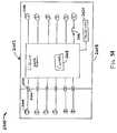
- FIG. 24illustrates one aspect of an electrically controlled pneumatic system 700.
- the pneumatic system 700comprises an internal or external source of pressurized gas.
- the pneumatic system 700comprises a cylinder 622 as a source of pressurized gas that may be rechargeable with a preferred pressurized gas.
- the nonreplaceable/rechargeable sources (cylinders) of pressurized gascould also be effectively employed.
- the handle assembly 300may be provided with a port 616 for supplying pressurized gas from the external source 618 of pressurized gas.
- the electronic control module 603is in electrical communication with sensors and flow control elements to control the flow rate through the variable flow rate pneumatic valve 660 (and the directional control valve 610).
- the electronic control module 603provides flow control signal based on feedback signals S 1 to S n received from a plurality of sensors and a plurality of pressure measurement signals P 1 to P m received from a plurality of pressure sensors, where n and m are any positive integers.
- the pneumatic systemis in fluid communication with the first and second supply lines 540, 542 and the measurement circuit 732.
- the measurement circuit 732receives pressure signals P 1 to P m from the variable flow rate pneumatic valve 660 and the first and second supply lines 540, 542 and provides a feedback signal 736 to the controller 702 that is proportional to the flow rate in the pneumatic system.
- the measurement circuit 732provides the feedback signal 736 in digital or any suitable form.
- the measurement circuit 732receives pressure inputs P 1 , P 2 , P 4 , P 5 ...P m from the various pressure sensors fluidically coupled throughout the pneumatic system.
- a pressure sensor 541 1may be fluidically coupled to the input supply line 650 at the inlet portion of the valve 660 upstream of the closure mechanism 730 to measure the inlet pressure P 1 , which in one aspect is the same as the supply 622 pressure.
- Pressure sensor 541 2may be fluidically coupled to the outlet of the valve 660 to measure the pressure P 2 downstream of the closure mechanism 730 in the supply line 680.
- the pressure sensors 541 1 and 541 2may be configured as a single differential pressure sensor. It is well known to calculate flow rate through an orifice based on the differential pressure ⁇ P across the orifice.
- Pressure sensor 541 3may be fluidically coupled to the first outlet of the directional control valve 610 to measure the pressure P 3 in the first supply line 540.
- Pressure sensor 541 4may be fluidically coupled to the second outlet of the directional control valve 610 to measure the pressure P 4 in the second supply line 542.
- Other pressure sensors 541 mmay be fluidically coupled throughout the pneumatic system to measure the corresponding pressure P m in the pneumatic system.
- the controller 702 and/or the measurement circuit 732also receive feedback signals S 1 to S n from a plurality of sensors disposed throughout the instrument 10.
- the sensorsmay comprise limit switches, solid state switches, relays, and/or flow sensors.
- the controller 702receives a feedback signal 736 from the measurement circuit 732.
- the feedback signal 736is proportional to the flow rate through the variable flow rate pneumatic valve 660 and may be based on the measured pressures P 1 to P m from the respective pressure sensors 541 1 to 541 m .
- the controller 702generates a control signal 738 that is provided to the actuator 706 to control the closure mechanism 730, which sets the flow rate through the variable flow rate pneumatic valve 660.
- the controller 702may comprise a microprocessor to execute a suitable control algorithm to relate the actual flow rate feedback signal 736 provided by the measurement circuit 732 to the energizing control signal 738 provided to the actuator 706 to control the closure mechanism 730 to achieve the desired flow rate through the flow-through portion of the variable flow rate pneumatic valve 660.
- the control algorithmmay be any suitable proportional, derivative, integral control algorithm, or any combination thereof.
- the actuator 706sends a control signal 740 to actuate a closure mechanism 730 located in the flow path 742 of the flow-through portion 734 of the variable flow rate pneumatic valve 660.
- the variable flow rate pneumatic valve 660may comprise various types of electrically actuated closure mechanisms 730 located in the flow path 742 of the flow-through portion 734 to control the gas discharge rate therethrough.
- the closure mechanism 730, pressure sensors P 1 -P m and the measurement circuit 732, the controller 702, and the actuator 706form a closed loop control system to control the gas discharge rate through the pneumatic system.
- the closure mechanism 730includes electrically controlled elements or components such as one or more solenoids, piezo-actuators, or electric motors, or any combination thereof.
- the controller 702 and the actuator 706are operably controlled by the controller 702 and the actuator 706 to selectively control the closure mechanism 730.
- the flow rate or discharge of the gas through the variable flow rate pneumatic valve 660 into the pneumatic drive member 500 comprising the actuation cylinder assembly 501may be determined by the state of the closure mechanism 730 and the pressure throughout the pneumatic system.
- the controller 702also generates a control signal 746 to the direction control valve 610 to select either the first supply conduit 540 or the second supply conduit 542 as the gas discharge path. This may be done to control the direction of the actuation cylinder assembly 501 at the beginning-of-stroke or at the end-of-stroke.
- the controller 702may control the actuation of a solenoid or piezo-actuator to control the gas discharge rate of the pressurized gas through the variable flow rate gas discharge valve 660.
- the closure mechanism 730may comprise a solenoid or a piezo-actuator.
- the controller 702may be configured to provide a control signal 738 in the form of a series of electrical pulses to the actuator 706 that is suitable to actuate the solenoid or piezo-actuator in a pulsed manner.
- the actuator 706may comprise a pulse drive circuit to suitably drive the solenoid or piezo-actuator with a series of electrical pulses.
- the controller 702respectively increases or decreases the frequency of the pulses.
- the actuator 740applies the pulses to the solenoid or piezo-actuator.
- the closure mechanism 730may comprise an element with a controlled variable internal orifice located in the flow-through portion 734 of the variable pneumatic valve 660.
- One such closure mechanismmay be an iris-type diaphragm control valve actuated by a motor.
- An iris-type diaphragm flow valveincludes a number of fingers or blades that extend into the flow-through portion 734 and form a circular shutter having a variable orifice that is controlled by the rotation of a motor coupled to the iris-type diaphragm flow valve.
- the degree to which the fingers extend into the flow path 742controls the radius of the orifice hence the amount of fluid that may flow therethrough and hence the flow rate through the variable flow rate pneumatic valve 660.
- the actuator 706 for the iris-type valvemay be a motor adapted and configured to drive the iris-type valve.
- the motorcontrols the diameter of the variable opening or orifice to control the discharge rate of the pressurized gas in the flow-through portion 734 of the variable flow rate pneumatic valve 660.
- the diameter of the orifice of the valvemay be set by the controller 702 for a desired flow rate.
- the actual flow ratemay be determined by the measurement circuit 732 based on the measured pressures P 1 to P m from the respective pressure sensors 541 1 to 541 4 and/or signals S 1 to S n from other sensors (such as for example, various flow sensors disposed throughout the pneumatic system).
- the flow rate through the flow-through portion 734may be determined based on the diameter of the orifice of the valve and the differential pressure ⁇ P (P 2 to P 1 ) cross the orifice.
- the controller 702Based on the feedback signal 736, the controller 702 provides a control signal 738 to the actuator 730 that is suitable to control the valve motor.
- the actuator 730sets the desired gas discharge flow rate by providing a suitable control signal to the iris-type valve mechanism to set the internal orifice diameter to produce the desired flow rate.
- variable flow rate pneumatic valve 660may be electrically coupled to the activation trigger 670 and the valve activation sensor 662.
- the activation trigger 670 and activation sensor 662are coupled to the controller 702.
- the valve activation sensor 662is coupled to the activation trigger 670 to detect when the activation trigger 670 has been drawn in (or "closed") toward the pistol grip portion 342 of the handle assembly 300 by the operator to thereby actuate the cutting/stapling operation by the end effector 12.
- the valve activation sensor 662may be a proportional sensor such as, for example, a rheostat or variable resistor.
- the valve activation sensor 662detects the movement, and sends an electrical signal indicative of the desired discharge rate of the pressurized gas to be supplied by the variable rate pneumatic valve 600 to the pneumatic actuation cylinder assembly 501.
- the output of the actuator 706generally may be proportional to the amount of movement of the actuation trigger 670. That is, if the operator only draws or closes the actuation trigger 670 in a little bit, the output of the actuator 706 is relatively low (e.g., low flow rate).
- the output of the actuator 706is at its maximum (e.g., highest flow rate).
- the harder the user pulls on the actuation trigger 670the more output signal is applied to the actuator 706, causing greater gas discharge flow rates through the flow-through portion 734 of the variable flow rate pneumatic valve 660.
- the valve activation sensor 662provides a proportional signal to the controller 702, which sends a control signal 738 to the actuator 706 to actuate the closure mechanism 730.
- variable flow rate pneumatic valve 660increases to permit the flow rate of the gas to increase therethrough.
- quickly squeezing the activation trigger 670may cause the firing rate of the device to increase and slowing the rate that the activation trigger 670 is squeezed slows the firing rate.
- the amount of gas flow permitted through the variable flow rate pneumatic valve 660can be substantially proportionate to the amount of manual force applied to the activation trigger 670.
- variable flow rate pneumatic valve 660may be electronically controlled such that upon actuation of the activation trigger, the variable flow rate pneumatic valve 660 digitally spurts gas therefrom.
- the variable flow rate pneumatic valve 660discharges a small amount of gas in a pulse manner and the harder that the activation trigger 670 is squeezed, the closer the pulses will be.
- Such arrangementserves to selectively regulate the volume of gas employed to actuate the device.
- the actuation mechanismmay comprises a different type of mechanism that is not pivotally supported relative to the handle assembly as is the activation trigger 670.
- the activation triggermay comprise a spring actuated slide switch, etc. Accordingly, the protection afforded to those aspects of the present invention should not be solely limited to aspects employing a pivoting actuated trigger.
- each of the pressure sensors 541 1 to 541mmay be coupled to a visual display to display the respective measured pressures P 1 to P m in any of the supply lines 650, 680, 540, 542 in the pneumatic system as shown in FIGS. 8 and 26 .
- the displayprovides a visual indication of the pressure readings P 1 to P m by each of the respective pressure sensors 541 1 to 541 m to a clinician.
- One or more windowsmay be provided through a corresponding portion of the handle assembly 300 to enable the clinician to view the pressure displayed by the pressure sensor 541 1 or other arrangements may be employed to enable the clinician to view the pressure displayed by the pressure sensor 541 1 during use.
- the pressure displaymay be coupled to additional circuits to provide an electronic signal indication of the pressure readings P 1 to P m by any of the supply lines 650, 680, 540, 542 to the controller 702.
- the pressure sensors 541 1 -541 mprovide feedback signals P 1 -P m to the controller 702 and the pressure display provides feedback to the clinician of the forces encountered during the firing stroke.
- the force necessary to actuate the firing mechanismis directly proportionate to the pressure in the cylinder assembly 501. If those forces are small, then the cylinder assembly 501 does not require large pressures to be actuated.
- the pressure displayserves to provide the clinician with a proportionate reading to the forces being experienced by the end effector.
- an audible outlet 545may be provided in the supply line 540 as shown in FIG. 8C .
- Such audible outletpermits a small amount of gas to be released from the supply line 540.
- the ensuing whistle pitch caused from the discharge of that gaswould increase as the pressure forces increased.
- the cliniciancan then relate the pitch of the whistle to the forces experienced by the firing mechanism.
- Such arrangementprovides the clinician with an audible feedback mechanism for monitoring the firing forces being experienced by the drive system 500 and ultimately the firing mechanism.
- a limit switch 546may be provided within the distal spine segment 110 for detecting an activation member 547 embedded into or otherwise attached to the firing rod 35 as shown in FIG. 11 .
- the activation member 547is so located such that when the firing bar 35 and firing mechanism reaches the end of the firing stroke, the activation member 547 is detected by the limit switch 546 which may be electrically coupled to the controller 702 and the directional control valve 610 for transmitting an appropriate signal S n thereto.
- the directional control valve 610may be configured to automatically shift to the retract position and to permit the firing mechanism to be retracted.
- the limit switch 546may be coupled to an indication member generally designated as 549 in FIG. 8 .
- the indication membermay provide the clinician with an audible signal, a visual signal or a combination of audible and visual signals indicating that the firing mechanism has reached the end of the firing stroke.
- the indication membermay comprise a sound generating device, an LED, a vibration generating device, and/or a combination of such devices.
- the limit switch 546 and related control componentsmay be powered by the battery 704 supported in the housing assembly 300 or it may be provided with electrical power from an external source of electrical power.
- various non-limiting aspects of the present inventionmay be provided with a means for providing the clinician with a visual and/or audible signal indicating that the firing mechanism has reached the end of the firing stroke and/or a means for automatically pneumatically retracting the firing mechanism to the unactuated position.
- a locking protrusion 39may be formed on the bottom of the piston bar 35.
- the arm 118 of the locking spring 112applies a biasing force to the distal end of the cylinder assembly 501. Because the cylinder assembly 501 is pivotally mounted within the distal spine segment 110 by trunions 519, the distal end of the cylinder assembly 501 pivots downwardly within the distal spine segment 110 and further causes the locking protrusion 39 on the piston bar 35 to drop into a locking opening 21 in the elongate channel 20.
- Such arrangementserves to lock the knife assembly 30 in the retracted position by virtue of the frictional engagement of the locking protrusion 39 with the portions of the elongate channel 20 defining the locking opening therein.
- the locking protrusion 39has a proximal ramp surface 39' and a distal ramp surface 39" to enable the locking protrusion to easily enter and exit the locking opening in the elongate channel 20.
- FIGS. 12-16Aillustrate another aspect of the instrument wherein the drive member 500 comprises a cylinder assembly 800 that is similar in construction as cylinder assembly 501 described above, except for the differences noted below.
- springs 850, 852are employed to retract the piston bar 35.
- the cylinder assembly 800includes a first housing 810 that has a first closed end 812 and a first supply port 813 therethrough.
- a first supply line 840is attached to the first closed end 812 to supply pressurized gas through the first supply port 813.
- the first cylinder housing 810lacks the second opening 529 that was described in connection with various aspects described above.
- a second cylinder housing 820is slidably received in the first cylinder housing 810 and has a second closed proximal end 822 that has a first piston head 828 formed thereon.
- a first cylinder area 815is defined between the first closed end 812 and the first piston head 828.
- a first retraction spring 850is provided between the first piston head 828 and a first flange 817 formed on the distal end of the first cylinder housing 810. The first retraction spring 850 serves to bias the second cylinder housing 820 into the retracted position in the first cylinder 810 as shown in FIG. 12 .
- the piston bar 35has a stepped end 35' that is sized to enter the second distal end 824 of the second cylinder housing 820.
- a second flange 825is formed on the second distal end 824 to achieve a substantially siding seal with the stepped portion 35' of the piston bar 35.
- a second piston head 830is provided on the proximal end of the stepped piston bar section 35' to define a third cylinder area 832 between the second piston head 830 and the first piston head 828.
- a first opening 827is provide through the first piston head 828 to enable air to pass between the first cylinder area 815 and the third cylinder area 832.
- a second retraction spring 852is provided between the second flange 825 and the second piston head 830 as shown in FIG. 12 to bias the second piston head 830 and stepped piston bar 35' to the fully retracted position within the second cylinder housing 820 as shown in FIG. 12 .
- the handle assembly 300is provided with a replaceable source 620 of pressurized gas as was discussed above. However, those of ordinary skill in the art will appreciate that nonreplaceable sources (cylinders) of pressurized gas could also be effectively employed. Still in other aspects, the handle assembly 300 may be provided with a port 616 for facilitating attachment of the directional control valve 610 and related components to an external source of pressurized gas 618. See FIG. 16A .
- the instrument 10could be coupled to the facility's compressed air line through a flexible supply line 617.
- the clinicianmoves the direction control valve selector switch 612 ( FIG. 1 ) or push buttons to the forward (extend) position and begins to squeeze the activation trigger 670 which permits the pressurized gas to flow from the cylinder 622 (or external source 618) through the supply line 680 through the directional control valve 610 and into the supply line 840.
- the pressurized gasflows from the first supply line 840 through the first supply port 813 into the first cylinder area 815, through the first opening 827 and into the third cylinder area 832. Gas entering the third cylinder area 832 causes the second piston head 830 and the stepped portion 35' of the piston bar 35 to move distally. After the second piston head 830 has moved to a fully extended position ( FIG.
- gas continuing to enter the first cylinder area 815biases the second housing 820 to its fully extended position.
- the clinician 30moves the directional valve selector switch 612 to the reverse (retract) position wherein the first supply line 840 is connected to a vent in the directional valve 610.
- Gas in the third cylinder area 832 and the first cylinder area 815is permitted to exit through the first supply port 813 into the supply line 840 and is ultimately vented through the directional valve 610.
- the second retract spring 852retracts the stepped portion 35' of the piston bar 35 into the second cylinder housing 820.
- the first retraction spring 850biases the second cylinder housing 520 into the first cylinder housing 810.
- the pressure sensor 541 3may be coupled to display electronically to the indication member 549.
- the pressure sensor 541 3is fluidically coupled to supply line 840 as shown in FIGS. 16 and 16A which can function in the manner described above and serves to provide the clinician with a proportionate reading to the forces being experienced by the end effector 12.
- an audible outlet 545may be provided in the supply line 840 as shown in FIG. 16B which can function in the manner described above to provide the clinician with an audible feedback mechanism for monitoring the firing forces being experienced by the drive system 500 and ultimately the firing mechanism.
- a limit switch 546FIG. 15
- FIGS. 17-21Aillustrate yet another aspect of the instrument wherein the drive member 500 comprises a bellows assembly 900.
- the bellows assembly 900may have a distal end 902 that is attached to distal portion 31 of the knife bar assembly 30.
- the distal end 902has a protrusion 904 formed thereon that sized to be received in an aperture 33 in portion 31.
- the protrusion 904may be frictionally received within the aperture 33 and/or retained therein by adhesive and/or welding.
- the distal portion 31may be constructed and configured as was described in detail above.
- the bellows assembly 900further includes an expandable/retractable bellows portion 910 that is sized to extend and retract within a bellows passage 117 in the distal spine segment as shown in FIG. 18 .
- the bellows portion 910may be formed with wire containment rings 912 as shown in FIG. 20 and may be attached to a base portion 914 that is non-movably attached to the distal spine segment 110 or comprises an integral portion of the distal spine segment 110.
- the base 914may be attached to the distal spine segment 110 by adhesive and/or screws.
- a supply port 916is provided through the bellows base 914 and a supply line 940 is attached to the supply port 916.
- the supply line 940is also coupled to the directional control valve 610 in the handle assembly 300. See FIGS.
- the directional control valve 610also communicates with a vacuum port 620 mounted in the handle assembly 300 through a vacuum line 922.
- the vacuum port 620is attachable to a source of vacuum 630 by, for example, a flexible line 632.
- the source of vacuummay be a permanent vacuum supply line in the facility.
- a flexible vacuum line 632may be attached from the port 620 to the vacuum source 630 to enable the clinician to freely manipulate the instrument.
- This instrumentmay be provided with the closure tube assembly 170 and closure trigger 302 arrangements described above.
- tissuemay be clamped in the end effector 12 in the manner described above.
- the clinicianmay fire the instrument as follows. The clinician moves the selector switch 612 ( FIG. 1 ) or buttons for the directional control valve 610 to the forward (extend) position and begins to squeeze the activation trigger 670. As the activation trigger 670 is squeezed, the rate valve 660 permits the pressurized gas to flow from the pressure source 620 ( FIG. 21 ) or 618 ( FIG. 21A ) to the directional control valve 610.
- the directional control valve 610permits the pressurized gas to flow through the supply line 940 into the bellows 910 causing it to extend distally.
- the bellows 910drives the knife assembly 30 through the end effector 12 severing the tissue clamped therein and driving the staples 70 in the staple cartridge 50 into forming contact with the bottom surface of the anvil 40.
- the clinicianreleases the activation trigger 670.
- the clinicianmoves the selector switch 612 for the directional control valve 610 to the retract position to thereby permit the source of vacuum 630 to be coupled to the supply line 940.
- the application of the vacuum to the supply line 940causes the bellows 910 to retract to its retracted position illustrated in FIG. 18 .
- the clinicianmay move the selector switch 612 or buttons to a position wherein the directional control valve stops the application of vacuum to the supply line 940.
- the remaining vacuum within the supply line 940may serve to retain the bellows 910 in the retracted position.
- a removable source 620 of pressurized gasis employed.
- such source of pressurized gascomprises a cylinder 622 that may be rechargeable.
- cylinder 622may be rechargeable.
- the handle assembly 300may be provided with a port 616 for supplying pressurized gas to an external source of pressurized gas.
- the instrument 10could be coupled to the facility's compressed air line through a flexible supply line 617. See FIG. 21A .
- a pressure sensor 541 3may be fluidically coupled to supply line 940 as shown in FIGS. 21 and 21A which can function in the manner described above and serves to provide the clinician with a proportionate reading to the forces being experienced by the end effector.
- an audible outlet 545may be provided in the supply line 940 as shown in FIG. 21B which can function in the manner described above to provide the clinician with an audible feedback mechanism for monitoring the firing forces being experienced by the drive system 500 and ultimately the firing mechanism.
- a limit switch 546FIG. 18
- FIG. 25illustrates various aspects of a surgical instrument with the capability to record instrument conditions at one or more times during use.
- FIG. 25shows a block diagram of a system 750 for recording conditions of the instrument 10. It will be appreciated that the system 750 may be implemented in aspects of the instrument 10 having pneumatically controlled or pneumatically-assisted firing, for example, as described with reference to aspects above. The aspects, however, are not limited in this context.
- the system 750may include various sensors 752, 754, 756, 758, 760, 762, 770 for sensing multiple instrument conditions.
- the sensorsmay be positioned, for example, on or within the instrument 10.
- the sensorsmay be dedicated sensors that provide output signals S 1 to S n only for the system 750, or may be dual-use sensors that perform other functions within the instrument 10.
- sensors 662, 720, 724, and logic module 726 described abovemay be configured to also provide output signals to the system 750.
- each sensorprovides a signal S 1 to S n to the memory device 703 ( FIG. 26 ) and/or to the controller 702.
- the memory device 703records the signals S 1 to S n as described in more detail below.
- the memory device 703may be any kind of device capable of storing or recording the sensor signals S 1 to S n .
- the memory device 703may include a microprocessor (e.g., controller 702), an Electrically Erasable Programmable Read Only Memory (EEPROM), or any other suitable storage device.
- the memory device 703may record the signals provided by the sensors in any suitable manner.
- the memory device 703may record a signal from a particular sensor when that signal changes states.
- the memory device 703may record a state of the system 750, e.g., the signals S 1 to S n from all of the sensors included in the system 750, when the signal S 1 to S n from any sensor changes states. This may provide a snap-shot of the state of the instrument 10.
- the memory device 703 and/or sensorsmay be implemented to include 1-WIRE bus products available from DALLAS SEMICONDUCTOR such as, for example, a 1-WIRE EEPROM.
- the memory device 703is externally accessible, allowing an outside device, such as a computer, to access the instrument conditions recorded by the memory device 703.
- the memory device 703may include a data port 764.
- the data port 764may provide the stored instrument conditions according to any wired or wireless communication protocol in, for example, serial or parallel format.
- the memory device 703may also include a removable medium 766 in addition to or instead of the output port 764.
- the removable medium 766may be any kind of suitable data storage device that can be removed from the instrument 10.
- the removable medium 766may include any suitable kind of flash memory, such as a Personal Computer Memory Card International Association (PCMCIA) card, a COMPACTFLASH card, a MULTIMEDIA card and/or a FLASHMEDIA card.
- PCMCIAPersonal Computer Memory Card International Association
- COMPACTFLASHCOMPACTFLASH card
- MULTIMEDIA cardMULTIMEDIA card
- FLASHMEDIA cardFLASHMEDIA card
- the removable medium 766may also include any suitable kind of disk-based storage
- FIG. 26illustrates one aspect of an instrument.
- the aspect shown in FIG. 26shows multiple sensors and a more detailed view of the electronic control module 603.
- the electronic control module 603comprises the controller 720, the memory device 703, the measurement circuit 732, the actuator 706, and the battery 704.
- the closure trigger sensor 752senses a condition of the closure trigger 302.
- the closure trigger sensor 752is positioned between the closure trigger 302 and closure pivot pin 306. It will be appreciated that pulling the closure trigger 302 toward the pistol grip 342 causes the closure trigger 302 to exert a force on the closure pivot pin 306.
- the sensor 752may be sensitive to this force, and generate a signal in response thereto, for example, as described above with respect to the valve actuation sensor 662 and FIGS.
- the closure trigger sensor 752may be a digital sensor that indicates only whether the closure trigger 302 is actuated or not actuated. In other various aspects, the closure trigger sensor 752 may be an analog sensor that indicates the force exerted on the closure trigger 302 and/or the position of the closure trigger 302. If the closure trigger sensor 752 is an analog sensor, an analog-to-digital converter may be logically positioned between the sensor 752 and the memory device 703. Also, it will be appreciated that the closure trigger sensor 752 may take any suitable form and be placed at any suitable location that allows sensing of the condition of the closure trigger 302.
- FIG. 27illustrates one aspect of an anvil closure sensor 754.
- the anvil closure sensor 754may sense whether the anvil 40 is closed.
- the sensor 754is positioned next to or within the anvil cam slots 28 of the elongate channel 20 as shown. As the anvil 40 is closed, the anvil pivots 43 slides through the anvil cam slots 28 and into contact with the sensor 754, causing the sensor 754 to generate a signal indicating that the anvil 40 is closed.
- the sensor 754may be any suitable kind of digital or analog sensor including a proximity sensor. It will be appreciated that when the anvil closure sensor 754 is an analog sensor, an analog-to-digital converter may be included logically between the sensor 754 and the memory device 703 and/or the controller 702.
- Anvil closure load sensor 756is shown placed on an inside bottom surface of the elongate channel 20.
- the sensor 756may be in contact with a bottom side of the staple cartridge 50 (not shown in FIG. 27 ).
- the anvil 40As the anvil 40 is closed, it exerts a force on the staple cartridge 50 which is transferred to the sensor 756.
- the sensor 756generates a signal S n .
- the signal S nmay be an analog signal proportional to the force exerted on the sensor 756 by the staple cartridge 50 and due to the closing of the anvil 40.
- the analog signalmay be provided to an analog-to-digital converter 768 to convert the analog signal to a digital signal before providing it to the memory device 703 and/or the controller 702. It will be appreciated that aspects where the sensor 756 is a digital or binary sensor may not include analog-to-digital converter 768.
- the firing trigger sensor 770senses the position and/or state of the firing trigger 310.
- the firing trigger sensor 770may take any of the forms described above, and may be analog or digital.
- FIG. 26shows an aspect of the firing trigger sensor 770.
- the firing trigger sensor 770is mounted between firing trigger 310 and firing trigger pivot pin 370. When firing trigger 310 is pulled, it will exert a force on the firing trigger pivot pin 370 that is sensed by the sensor 770.
- analog-to-digital converter 772is included logically between the firing trigger sensor 770 and the memory device 703 and/or the controller 702.
- FIG. 28illustrates one aspect of a knife position sensor 758 that is suitable for use with the pneumatically actuated piston bar portion 35 protruding from the knife assembly 30.
- the knife position sensor 758senses the position of the knife assembly 30 or cutting edge 38 within the elongate channel 20.
- the sensor 758includes a magnet 774 coupled to the piston bar portion 35 of the instrument 10.
- a coil 776is positioned around the piston bar portion 35.
- the piston bar portion 35 and magnet 774may move back and forth through the coil 776. This motion relative to the coil induces a voltage in the coil proportional to the position of the piston bar portion 35 within the coil and the cutting edge 38 within the elongate channel 20.
- This voltagemay be provided to the memory device 703 and/or the controller 702, for example, via analog-to-digital converter 778.
- the knife position sensor 758may instead be implemented as a series of digital sensors (not shown) placed at various positions on or within the elongate shaft assembly 100.
- the digital sensorsmay sense a feature of the piston bar portion 35 such as, for example, magnet 774, as the feature reciprocates through the elongate shaft assembly 100.
- the position of the piston bar portion 35 within the elongate shaft assembly 100, and by extension, the position of the knife assembly 30may be approximated as the position of the last digital sensor tripped.
- FIGS. 29 and 30illustrate one aspect of a cartridge present sensor 760.
- the cartridge present sensor 760may sense the presence of the staple cartridge 40 within the elongate channel 20.
- the cartridge present sensor 760may double as the cartridge lock-out sensor.
- a cartridge lockout sensorchanges states based on whether the end effector 12 includes a staple cartridge 40. For example, if the end effector 12 includes a staple cartridge 40, the lock-out sensor will be in a closed state, allowing current to flow, otherwise, if the end effector 12 does not include a staple cartridge 40, the lock-out sensor will be in an open state to prevent the activation of the instrument 10.
- the cartridge present sensor 760includes two contacts 780 and 782.
- the contacts 780, 782form an open circuit.
- the cartridge tray 68 of the staple cartridge 40contacts the contacts 780, 782, and a closed circuit is formed.
- the sensor 760may output a logic zero.
- the sensor 760may output a logic one.
- the output of the sensor 760is provided to the memory device 703 and/or the controller 702 as shown in FIG. 24 , for example.
- the cartridge condition sensor 762may indicate whether a cartridge 40 installed within the elongate channel 20 has been fired or spent. As the knife assembly 30 is translated through the end effector 12, it pushes the wedge sled 64, which fires the staple cartridge 40. Then the knife assembly 30 is translated back to its original position, leaving the wedge sled 64 at the distal end of the cartridge 40. Without the wedge sled 64 to guide it, the knife assembly 30 may fall into the locking opening 21 in the elongate channel 20. Sensor 762 may sense whether the knife assembly 30 is present in the locking opening 21, which indirectly indicates whether the cartridge 40 has been spent. It will be appreciated that in various aspects, sensor 762 may directly sense the presence of the wedge sled 64 at the proximate end of the cartridge 40, thus eliminating the need for the knife assembly 30 to fall into the locking opening 21.
- the valve actuation sensor 662is coupled to the activation trigger 670.
- the valve actuation sensor 662may be a digital on/off switch or may be an analog proportional sensor as described with reference to FIGS. 22A and 22B .
- the output of the valve actuation sensor 662is coupled to the memory device 703 and/or to the controller 702.
- the valve actuation sensor 662detects the movement of the activation trigger 670 it sends an actuation signal S n to the controller 702 to actuate the variable flow rate pneumatic valve 660.
- the valve actuation sensor 662is a digital on/off switch, it sends an electrical signal S n to the controller 702 to actuate the variable flow rate pneumatic valve 660.
- valve actuation sensor 662When the valve actuation sensor 662 is an analog proportional sensor, the sensor 662 provides an analog signal S n that is proportional to the pressure applied on the valve actuation sensor 662 by the activation trigger 670.
- the proportional output signal S nis provided to an analog-to-digital converter 786 to convert the analog signal to a digital signal before providing it to the memory device 703.
- the controller 702adjusts the variable flow rate pneumatic valve 660 to produce the desired flow rate of the pressurized gas as previously discussed based on the pressure applied to the valve actuation sensor 662 by the actuation trigger.
- FIGS. 31A and 31Billustrate one aspect of a process flow 2200 for operating aspects of the surgical instrument 10 configured as an endocutter and having the capability to record instrument conditions according to various aspects.
- the anvil 40 of the instrument 10may be closed. This causes the closure trigger sensor 752 and or the anvil closure sensor 756 to change state.
- the memory device 703may record the state of all of the sensors in the system 750 at box 2203.
- the instrument 10may be inserted into a patient. When the instrument is inserted, the anvil 40 may be opened and closed at box 2206, for example, to manipulate tissue at the surgical site. Each opening and closing of the anvil 40 causes the closure trigger sensor 752 and/or the anvil closure sensor 756 to change state.
- the memory device 703records the state of the system 750 at box 2205.
- tissueis clamped for cutting and stapling. If the anvil 40 is not closed at decision block 2210, continued clamping is required. If the anvil 40 is closed, then the sensors 752, 754 and/or 756 may change state, prompting the memory device 703 to record the state of the system at box 2213. This recording may include a closure pressure received from sensor 756. At box 2212, cutting and stapling may occur. Firing trigger sensor 770 may change state as the firing trigger 310 is pulled toward the pistol grip 342. Also, as the knife assembly 30 moves through the elongate channel 20, the knife position sensor 758 will change state. In response, the memory device 703 may record the state of the system 750 at box 2013.
- the knife assembly 30may return to a pre-firing position. Because the cartridge 50 has now been fired, the knife assembly 30 may fall into the locking opening 21, changing the state of cartridge condition sensor 762 and triggering the memory device 703 to record the state of the system 750 at box 2015.
- the anvil 40may then be opened to clear the tissue. This may cause one or more of the closure trigger sensor 752, anvil closure sensor 754 and anvil closure load sensor 756 to change state, resulting in a recordation of the state of the system 750 at box 2017.
- the anvil 40may be again closed at box 2220. This causes another state change for at least sensors 752 and 754, which in turn causes the memory device 703 to record the state of the system at box 2019. Then the instrument 10 may be removed from the patient at box 2222.
- the anvil 40may be opened at box 2224, triggering another recordation of the system state at box 2223.
- the spent cartridge 50may be removed from the end effector 12 at box 2226. This causes cartridge present sensor 760 to change state and cause a recordation of the system state at box 2225.
- Another cartridge 50may be inserted at box 2228. This causes a state change in the cartridge present sensor 760 and a recordation of the system state at box 2227. If the other cartridge 50 is a new cartridge, indicated at decision block 2230, its insertion may also cause a state change to cartridge condition sensor 762. In that case, the system state may be recorded at box 2231.
- FIG. 32shows one aspect of a memory map 2300 from the memory device 703.
- the memory map 2300includes a series of columns 2302, 2304, 2306, 2308, 2310, 2312, 2314, 2316 and rows (not labeled).
- Column 2302shows an event number for each of the rows.
- the other columnsrepresent the output of one sensor of the system 750. All of the sensor readings recorded at a given time may be recorded in the same row under the same event number. Hence, each row represents an instance where one or more of the signals from the sensors of the system 750 are recorded.
- Column 2304lists the closure load recorded at each event. This may reflect the output of anvil closure load sensor 756.
- Column 2306lists the firing stroke position. This may be derived from the knife position sensor 758. For example, the total travel of the knife assembly 30 may be divided into partitions. The number listed in column 2306 may represent the partition where the knife assembly 30 is currently present.
- the firing loadis listed in column 2308. This may be derived from the firing trigger sensor 770.
- the knife positionis listed at column 2310. The knife position may be derived from the knife position sensor 758 similar to the firing stroke. Whether the anvil 40 is open or closed may be listed at column 2312. This value may be derived from the output of the anvil closure sensor 754 and/or the anvil closure load sensor 756.
- Whether the wedge sled 64 is present, or whether the cartridge 50 is spent,may be indicated at column 2314. This value may be derived from the cartridge condition sensor 762. Finally, whether the cartridge 50 is present may be indicated a column 2316. This value may be derived from cartridge present sensor 760. It will be appreciated that various other values may be stored at memory device 703 including, for example, the end and beginning of firing strokes, for example, as measured by various other sensors.
- FIG. 33illustrates various aspects of a surgical instrument 2400.
- the surgical instrument 2400may be similar to the surgical instrument 10 described hereinabove, but also includes a status module 2402 releasably connected thereto.
- the status module 2402is shown in FIG. 33 as being connected to the exterior lower side piece of the handle assembly 300, it is understood that the status module 2402 may be connected to the surgical instrument 2400 at any suitable location.
- the handle assembly 300 of the surgical instrument 2400defines a recess structured and arranged to receive the status module 2402.
- FIG. 34illustrates a schematic of one aspect of a surgical instrument 2400 comprising a plurality of sensors 2404.
- the plurality of sensors 2404includes, for example, an articulation angle sensor, an anvil position sensor, a cartridge sensor, a closure trigger sensor, a closure force sensor, a firing force sensor, a knife position sensor, a lockout condition sensor, or any combination thereof.
- Each sensor 2404may be in electrical communication with a different contact 2406 (shown schematically in FIG. 34 ) positioned proximate the exterior of the surgical instrument 2400.
- the sensors 2404may be embodied in any suitable manner.
- the articulation angle sensormay be embodied as, for example, a potentiometer that comprises a portion of the articulation control 200 and outputs a signal that indicates the relative articulation angle of the end effector 12.
- the anvil position sensormay be embodied as, for example, the anvil closure sensor 754 discussed above.
- the cartridge sensormay be embodied as, for example, the cartridge present sensor 760 discussed above.
- the closure trigger sensormay be embodied as, for example, the closure trigger sensor 752 discussed above.
- the closure force sensormay be embodied as, for example, the anvil closure load sensor 756 discussed above.
- the firing force sensormay be embodied as, for example, the firing trigger sensor 770 discussed above.
- the knife position sensormay be embodied as, for example, the knife position sensor 758 discussed above.
- the lockout condition sensormay be embodied as, for example, the cartridge lockout sensor or the cartridge present sensor 760 discussed above
- the status module 2402comprises a housing 2408 structured and arranged to releasably connect to the surgical instrument 2400.
- the status module 2408comprises a plurality of contacts 2410 (shown schematically in FIG. 34 ), wherein each individual contact 2410 is structured and arranged to be in electrical communication with a different sensor 2404 of the surgical instrument 2400 when the housing 2408 is connected to the surgical instrument 2400.
- each contact 2410 of the status module 2402may be aligned with a respective corresponding contact 2406 of the surgical instrument 2400, thereby placing each contact 2410 of the status module 2402 in electrical communication with a different sensor 2404.
- the status module 2402further comprises a circuit 2412 (shown schematically in FIG. 34 ) in communication with at least one of the contacts 2410, and a plurality of indicators 2414 (shown schematically in FIG. 34 ). At least one of the indicators 2414 is in electrical communication with the circuit 2412.
- the circuit 2412comprises a drive circuit, and is structured and arranged to drive at least one of the indicators 2414. According to various aspects, the circuit 2412 may further comprise, as shown schematically in FIG. 34 , a switch 2416, a counter 2418, a transmitter 2420, or any combination thereof. In one aspect, the circuit is coupled to the electronic control module 603.
- the switch 2416is in electrical communication with at least one of the indicators 2414, and may be utilized to disable the respective indicator 2414 that is in electrical communication therewith.
- the switch 2416may comprise a portion of the status module 2402 other than the circuit 2412, or a portion of the surgical instrument 2400 other than the status module 2402.
- the switch 2416may be in electrical communication with the circuit 2412.
- the counter 2418may be utilized to determine the number of firings, the number of firings remaining and/or the post-clamping wait time. According to various aspects, the counter 2418 may comprise a portion of the status module 2402 other than the circuit 2412. According to other aspects, the counter 2418 may comprise a portion of the surgical instrument 2400 other than the status module 2402. For such aspects, the counter 2418 may be in electrical communication with the circuit 2412.
- the transmitter 2420may be utilized to wirelessly transmit information sensed by the plurality of sensors 2404 to a wireless receiver (not shown) associated with a monitor (not shown) that may be viewed by a user of the surgical instrument 2400 while the user is performing a procedure.
- the informationmay be wirelessly transmitted continuously or periodically.
- the displayed informationmay include, for example, firing progress information, compression load information, knife load information, number of firings, procedure time, compression wait time and/or battery level.
- the transmitter 2420may comprise a portion of the status module 2402 other than the circuit 2412, or a portion of the surgical instrument 2400 other than the status module 2402.
- the transmitter 2420may be in electrical communication with the circuit 2412.
- FIGS. 35-37illustrate various aspects of the status module 2402.
- the status module 2402may comprise different types of indicators 2414.
- the indicators 2414may comprise one or more visual indicators such as, for example, a light emitting diode, a multi-color light emitting diode and/or a display or any combination thereof.
- the displaymay comprise, for example, an alpha numeric display, a dot matrix display and/or a liquid crystal display.
- at least one of the indicators 2414may comprise an audible indicator such as, for example, an audio output device.
- the audible output devicemay be embodied as, for example, a speaker, and may be in electrical communication with the switch 2416.
- the indicators 2414may comprise at least one visual indicator and at least one audible indicator.
- FIG. 35illustrates one aspect of an indicator to provide audible and visual feedback.
- the indicators 2414may provide visual and audible feedback to a user of the surgical instrument 2400.
- an indicator 2414e.g., a light emitting diode
- Different indicators 2414may emit different colors of light.
- different hatchingindicates different colors.
- An indicator 2414e.g., a multi-color light emitting diode
- a multi-color light emitting diodemay emit green light if a loaded staple cartridge 50 is in the elongate channel 20, yellow light if a spent staple cartridge 50 is in the elongate channel 20, or red light if a staple cartridge 50 is not in the channel 20.
- a multi-color light emitting diodemay emit green light if the cutting force being exerted is in a normal range, yellow light if the cutting force being exerted is in an elevated range, or red light if the cutting force being exerted is in a high load range. It is understood that the indicators 2414 may be utilized for multiple status indications of other functions of the surgical instrument 2400 such as, for example, battery level.
- a line of indicators 2414may be utilized to indicate the progression of the knife assembly 30, the percentage of the maximum closure force being exerted, the percentage of the maximum firing force being exerted, or the current articulation angle of the end effector 12. Such indications may provide a user of the surgical instrument 2400 with feedback concerning the forces involved in operating the surgical instrument 2400 and feedback as to how close the surgical instrument 2400 is operating to its maximum capacity.
- the status module 2402may comprise any number of lines of indicators 2414.
- FIG. 36illustrates one aspect of a status module.
- the status module 2402may comprise indicators 2414 (e.g., light emitting diodes) arranged in two circular orientations.
- the status module 2402may be capable of providing more concurrent information to a user of the surgical instrument 2400 than the status module 2402 shown in FIG. 35 .
- two circular arrangements of indicatorsare shown in FIG. 36 , it is understood that the status module 2402 may comprise any number of indicators 2414 arranged in any number of orientations.
- the status module 2402may comprises indicators 2414 arranged in a pyramid pattern.
- FIG. 37illustrates one aspect of a status module.
- the indicators 2414 of the status module 2402may comprise a line of light emitting diodes and at least one display (e.g., a liquid crystal display).
- the status module 2402may be capable of providing more concurrent information to a user of the surgical instrument 2400 than the status module 2402 shown in FIG. 35 or FIG. 36 .
- the light emitting diodesmay show reaction force at the anvil 40 and staple cartridge 50, the battery level, or the articulation angle in the form of a bar graph.
- the displaymay show information concerning closure forces, firing forces, the number of firings remaining, post-clamping wait time, stroke progression, or articulation angle in the form of digits.
- the devices disclosed hereincan be designed to be disposed of after a single use, or they can be designed to be used multiple times. In either case, however, the device can be reconditioned for reuse after at least one use. Reconditioning can include an combination of the steps of disassembly of the device, followed by cleaning or replacement of particular pieces, and subsequent reassembly.
- the devicecan be disassembled, and any number of particular pieces or parts of the device can be selectively replaced or removed in any combination.
- the devicecan be reassembled for subsequent use either at a reconditioning facility, or by a surgical team immediately prior to a surgical procedure.
- the invention described hereinwill be processed before surgery.
- a new or used instrumentis obtained and, if necessary, cleaned.
- the instrumentcan then be sterilized.
- the instrumentis placed in a closed and sealed container, such as a plastic or TYVEK® bag.
- the container and instrumentare then placed in a field of radiation that can penetrate the container, such as gamma radiation, x-rays, or higher energy electrons.
- the radiationkills bacteria on the instrument and in the container.
- the sterilized instrumentcan then be stored in the sterile container.
- the sealed containerkeeps the instrument sterile until it is opened in the medical facility.
Landscapes
- Health & Medical Sciences (AREA)
- Surgery (AREA)
- Life Sciences & Earth Sciences (AREA)
- Engineering & Computer Science (AREA)
- Molecular Biology (AREA)
- Biomedical Technology (AREA)
- Heart & Thoracic Surgery (AREA)
- Medical Informatics (AREA)
- Nuclear Medicine, Radiotherapy & Molecular Imaging (AREA)
- Animal Behavior & Ethology (AREA)
- General Health & Medical Sciences (AREA)
- Public Health (AREA)
- Veterinary Medicine (AREA)
- Robotics (AREA)
- Surgical Instruments (AREA)
Description
- The present disclosure is generally directed to surgical apparatuses and methods and, more particularly, pneumatically powered surgical cutting and fastening instruments. The surgical apparatuses and methods may have application in conventional endoscopic and open surgical instrumentation as well as application in robotic-assisted surgery.
- Surgical cutting and fastening instruments (staplers) have been used in the prior art to simultaneously make a longitudinal incision in tissue and apply lines of staples on opposing sides of the incision. Such instruments commonly include a pair of cooperating jaw members that, if the instrument is intended for endoscopic or laparoscopic applications, are capable of passing through a cannula passageway. One of the jaw members receives a staple cartridge having at least two laterally spaced rows of staples. The other jaw member defines an anvil having staple-forming pockets aligned with the rows of staples in the cartridge. The instrument includes a plurality of reciprocating wedges which, when driven distally, pass through openings in the staple cartridge and engage drivers supporting the staples to effect the firing of the staples toward the anvil.
- Over the years, a variety of different methods for actuating the cutting and staple deployment components have been developed. For example,
U.S. Patent No. 6,978,921 to Shelton, IV et al . discloses a surgical stapling instrument that employs tissue severing and staple deployment components that are driven through manual actuation of various trigger mechanisms on the handle. Other surgical stapling apparatuses have been developed that employ battery powered motors. Such a device is disclosed inU.S. Patent No. 5,954,259 to Viola et al . - Still other surgical staplers are actuated by a source of pressurized gas. For example,
U.S. Patent No. 6,619,529 to Green et al . discloses a surgical stapler that employs a source of pressurized gas in the handle that is used to power a cylinder that is also located within the handle. The cylinder houses a piston assembly that is actuated by admission of the pressurized gas into the cylinder. The piston is configured to coact with components located in the elongated tube portion and handle member to cause the deployment of the staples and the surgical knife in the distally mounted end effector. Such design, however, employs a complex collection of components for transmitting the motion of the handle-mounted piston to the components located in the end effector portion of the device. In addition, when using such a device, there is a risk that the power source becomes depleted during the surgical procedure because there is no way of monitoring the amount of gas remaining in the gas cartridge. If this occurs during the firing or retraction cycles, such devices lack means for easily exchanging the spent container with a new container or auxiliary power source. - Another pneumatically powered surgical stapling device is disclosed in US Patent Publication No.
US 2006/0151567 to Roy . This device employs a pneumatically powered motor or piston system supported in the handle of the device for creating a motion that is employed to actuate the end effector. This device may be powered by removable cartridges or from an external power source, such as the hospital's existing pneumatic air or gas supply. WO 2004/032760 discloses a surgical stapler which includes or onto which a tool assembly can be mounted for deforming a plurality of surgical fasteners through and fastening tissue includes a housing having a fixed handle and a clamping handle mountable to the housing.EP 1785097 discloses articulation joints for use in connection with a surgical instrument that has a portion that must be passed through a trocar or similar structure and then articulated relative to another portion of the instrument received within the trocar. Various embodiments of the articulation joint include at least one fluid-actuated cylinder or flexible driven member to articulate the surgical implement relative to the handle assembly of the instrument.- Such pneumatically powered devices that employ cartridges or containers in the handle portion of the device are also hampered by the size of the gas cylinder required to store the pressurized gas at sufficient volumes to facilitate actuation of the device a desired number of times at a minimum usable pressure. In the past, devices designed for large numbers of applications/procedures would either require a large cylinder to be used or, if smaller cylinders were used, such cylinders would have undesirably high pressures. In addition, devices that employ removable cartridges that can be used an unlimited number of times must be reprocessed and resterilized. Such arrangements can dramatically change performance capabilities and may therefore be less desirable.
- Other problems exist with prior pneumatically powered surgical apparatuses. For example, once the surgeon activates the instrument through a single switch or activation trigger, the instrument progresses through or at least attempts to complete the firing cycle. Thereafter, the firing components may be retracted by the drive system. Prior pneumatically actuated instruments also lack suitable electrical control mechanisms to control the actuated pneumatic components. Prior pneumatically actuated surgical apparatuses also lack suitable electrical recording capabilities to provide information associated with the pneumatically actuated surgical apparatus to the surgeon.
- Consequently there is a need for a pneumatically powered and electrically controlled surgical stapling device that does not require the use of an extensive collection of components to transfer the pneumatically generated stapling and firing motions to the end effector components.
- There is a need for a pneumatically powered instrument with electrical control mechanisms. Conventional pneumatically powered instruments employ pressurized gas to actuate cutting and/or stapling functions. Once the pneumatic cylinder is actuated, however, it is difficult to control the flow rate of the gas from the pneumatic cylinder or the pressurization of the pneumatic system. Thus, there is a need to integrate pneumatic actuators with one or more electrical control elements to control the rate of release of the pressurized gas from the pneumatic cylinder and thus control the pressurization of the pneumatic system. It also would be advantageous to employ the electrical control elements to control the release of the gas from the pneumatic cylinder at a variable rate.
- There is another need for a pneumatically powered instrument with electrical recording capabilities. One reason for employing electrical recording capabilities is for the clinician to be able to verify via an endoscope that the desired location for the cut has been achieved, including a sufficient amount of tissue has been captured between opposing jaws. Otherwise, opposing jaws may be drawn too close together, especially pinching at their distal ends, and thus not effectively forming closed staples in the severed tissue. At the other extreme, an excessive amount of clamped tissue may cause binding and an incomplete firing. When endoscopic surgical instruments fail, they are often returned to the manufacturer, or other entity, for analysis of the failure. If the failure resulted in a critical class of defect in the instrument, it is necessary for the manufacturer to determine the cause of the failure and determine whether a design change is required. In that case, the manufacturer may spend many hundreds of man-hours analyzing a failed instrument and attempting to reconstruct the conditions under which it failed based only on the damage to the instrument. It can be expensive and very challenging to analyze instrument failures in this way. Also, many of these analyses simply conclude that the failure was due to improper use of the instrument. Thus, there is a need for a pneumatically powered instrument that employs a number of sensors and electrical recording elements to selectively discharge the activation of the pneumatic cylinder and/or to selectively pressurize the pneumatic system and record any condition of the instrument based on readings from the sensors.
- There is a further need for a pneumatically powered instrument with electrical feedback capabilities. Once the instrument closes upon tissue before firing, electrical feedback enables the clinician to verify via an endoscope that the desired location for the cut has been achieved, including a sufficient amount of tissue has been captured between opposing jaws.
- Otherwise, opposing jaws may be drawn too close together, especially pinching at their distal ends, and thus not effectively forming closed staples in the severed tissue. At the other extreme, an excessive amount of clamped tissue may cause binding and an incomplete firing.
- Endoscopic staplers/cutters continue to increase in complexity and function with each generation. One of the main reasons for this is the quest for lower force-to-fire (FTF) to a level that all or a great majority of surgeons can handle. Surgeons typically prefer to experience proportionate force distribution to that being experienced by the end-effector in the forming the staple to assure them that the cutting/stapling cycle is complete, with the upper limit within the capabilities of most surgeons (usually around 7-14 kg (15-30 lbs)). They also typically want to maintain control of deploying the staple and being able to stop at anytime if the forces felt in the handle of the device feel too great or for some other clinical reason. These user-feedback effects are not suitably realizable in present pneumatically powered instruments. As a result, there is a general lack of acceptance by physicians of pneumatically powered instruments where the cutting/stapling operation is actuated by merely pressing a button.
- With current surgical instruments, the status of the instrument is generally not provided to a user (clinician) of the surgical instrument during a procedure. For example, with current mechanical endocutters, the presence of the staple cartridge, the position of the knife, the time elapsed since clamping, and the magnitude of the firing force are generally not provided to the user. Without visual and/or audible feedback, each user must rely on his or her own "feel" to determine the status of the surgical instrument, thereby creating inefficiencies, inconsistencies, and potential damage to the surgical instrument.
- One aspect provides a surgical instrument comprising an end effector. The end effector comprises a moveable cutting instrument for cutting an object positioned in the end effector. A pneumatically-actuated drive member is coupled to the end effector. An electrically controlled variable flow rate pneumatic valve is coupled to the pneumatically-actuated drive member. An electronic control module is coupled to the electrically controlled variable flow rate pneumatic valve to control the flow rate therethrough.
- Various aspects of a surgical apparatus and method are described herein by way of example in conjunction with the following figures, wherein like numerals may be used to describe like parts and wherein:
FIG. 1 is a perspective view of an aspect of a surgical cutting and fastening instrument;FIG. 2 is an exploded assembly view of an aspect of an end effector arrangement that may be employed in connection with various aspects of the surgical cutting and fastening instrument;FIG. 3 is a top view of the end effector ofFIGS. 1 and2 with the anvil portion removed therefrom and the closure tube assembly illustrated in phantom lines;FIG. 4 is a cross-sectional side elevational view of the end effector arrangement ofFIG. 3 with the anvil portion attached thereto and shown in an open position;FIG. 5 is a cross-sectional top view of a portion of an articulation control that may be employed with various aspects of the surgical cutting and fastening instrument;FIG. 6 is a top cross-sectional view illustrating the articulation of the end effector depicted inFIG. 1 ;FIG. 7 is an exploded assembly view illustrating an aspect of a closure tube assembly and shuttle arrangement supported within the handle assembly with other components housed within the housing assembly being omitted for clarity;FIG. 8 is a cross-sectional view of a housing assembly arrangement of various aspects of the surgical cutting and fastening instrument;FIG. 8A is a partial cross-sectional view of a portion of a closure trigger locking system that may be employed in connection with various aspects of the surgical cutting and fastening instrument;FIG. 8B is a cross-sectional view of another handle assembly aspect of the surgical cutting and fastening instrument wherein the source of pressurized gas is external to the handle assembly;FIG. 8C is a cross-sectional view of another handle assembly aspect of the surgical cutting and fastening instrument;FIG. 9 is another cross-sectional view of the handle assembly ofFIG. 8 ;FIG. 10 is a side view of a knife bar arrangement and a firing drive member that comprises a two stage cylinder assembly of various aspects of the surgical cutting and fastening instrument with the cylinder assembly shown in cross-section;FIG. 11 is another side view of the knife bar and two stage cylinder arrangements depicted inFIG. 10 with the knife bar in the extended position;FIG. 12 is a side view of another knife bar and firing drive member arrangement of the surgical cutting and fastening instrument with the knife bar being retracted into a cylinder assembly shown in cross-section;FIG. 13 is another side view of the knife bar and cylinder arrangements depicted inFIG. 12 with the knife bar in the extended position;FIG. 14 is a top view of an end effector and spine assembly arrangement housing the cylinder and knife bar arrangements depicted inFIGS. 12 and 13 ;FIG. 15 is a cross-sectional side elevational view of the end effector and spine assembly arrangement depicted inFIG. 14 with the anvil portion attached thereto and in the open position;FIG. 16 is a cross-sectional view of a handle assembly that may be used in connection with the aspect depicted inFIGS. 12-15 ;FIG. 16A is a cross-sectional view of another handle assembly that may be used in connection with the aspect depicted inFIGS. 12-15 wherein the source of pressurized gas is external to the handle assembly;FIG. 16B is a cross-sectional view of another handle assembly aspect of the surgical cutting and fastening instrument;FIG. 17 is a top view of another knife bar and spine assembly arrangement that supports another firing drive member in the form of a bellows assembly of another aspect of the surgical cutting and fastening instrument;FIG. 18 is a cross-sectional side elevational view of the end effector and spine assembly arrangements of the aspect depicted inFIG. 17 ;FIG. 19 is a partial cross-sectional assembly view of a bellows assembly of the aspects depicted inFIGS. 17 and 18 ;FIG. 20 is an enlarged view of a portion of the bellows assembly ofFIG. 19 ;FIG. 21 is a cross-sectional view of a handle assembly aspect that may be used in connection with the aspects depicted inFIGS. 17-20 ;FIG. 21A is a cross-sectional view of another handle assembly aspect that may be used in connection with the aspects ofFIGS. 17-20 wherein the source of pressurized gas is external to the handle assembly;FIG. 21B is a cross-sectional view of another handle assembly aspect of the surgical cutting and fastening instrument;FIGS. 22A and 22B illustrate various aspects of a proportional sensor.FIG. 23 is a schematic diagram of one aspect of an electrical circuit of the instrument according to various aspects thereof.FIG. 24 illustrates one aspect of an electrically controlled pneumatic system.FIG. 25 illustrates various aspects of a surgical instrument with the capability to record instrument conditions at one or more times during use.FIG. 26 illustrates one aspect of a closure trigger sensor.FIG. 27 illustrates one aspect of an anvil closure sensor.FIG. 28 illustrates one aspect of a knife position sensor that is suitable for use with the pneumatically actuated piston bar portion protruding from the knife assembly.FIGS. 29 and 30 illustrate one aspect of a cartridge present sensor.FIGS. 31A and31B illustrate one aspect of a process flow for operating aspects of a surgical instrument configured as an endocutter and having the capability to record instrument conditions according to various aspects.FIG. 32 shows one aspect of a memory map from the memory device.FIG. 33 illustrates various aspects of a surgical instrument.FIG. 34 illustrates a schematic of one aspect of a surgical instrument comprising a plurality of sensors.FIG. 35 illustrates one aspect of an indicator to provide audible and visual feedback.FIG. 36 illustrates one aspect of a status module.FIG. 37 illustrates one aspect of a status module.- The invention is as disclosed in the appended set of claims.
- In one aspect, a pneumatically powered instrument comprises an integrated pneumatic actuation system and electrical control, recording, and/or feedback elements. In one aspect, a pneumatic actuation system is combined with an electrical control system to pneumatically actuate the instrument and electrically control the flow rate in the pneumatic system. An actuator may be employed to electrically control the pressurization of the pneumatic system. The control system receives pressurized gas from a source and produces an electrical output to actuate an element of the instrument employing at least one electrical component or element. The control system may be employed to control elements of a surgical cutting and fastening device. The cutting and fastening elements are pneumatically operable by a controller. Thus, the actuation of a pneumatic cylinder may be controlled with a pressurized gas and a controller. The controller controls the rate at which the pressurized gas is released within the pneumatic system. The controller may be employed to control one or more flow control elements such as solenoids, piezoelectric actuators, or electric motors. These flow control elements may be employed to open and close valves and other closure mechanisms to control the rate of discharge of the pressurized gas into the actuation cylinder. Additional flow control elements may be employed to release the pressurized gas at a variable rate. The aspects are not limited in this context.
- In another aspect, a pneumatically powered instrument comprises electrical recording capabilities. The instrument may comprise an information recording system including, for example, a battery, circuit element, and memory device integrated with the pneumatically powered instrument. The information recording system may be employed to record information associated with the instrument. The instrument may comprise a switch, trigger, actuator, or other elements or techniques to selectively discharge a pressurized pneumatic gas to actuate the instrument. In one aspect, the instrument may further comprise one or more sensors to enhance the information gathered by the recording system. Various sensors may be employed to provide information to the information recording system. The sensors include sensors to measure and/or record the number of actuations and reprocessings, the force to actuate or close an end effector of the instrument, the clamping force of the end effector, the pressure exerted on tissue, whether a cartridge is loaded in the instrument, the status of the cartridge, the lockout status of the instrument, the pressure in the pneumatic actuation cylinder, whether the surgical instrument is ready-to-fire, and so forth. The aspects are not limited in this context.
- In another aspect, a pneumatically powered instrument comprises electrical feedback capabilities. The pneumatically powered instrument may be integrated with a feedback module. The feedback module may be self contained and adapted to connect to a plurality of contacts disposed throughout the instrument, an electrical circuit element, and a plurality of indicators. The feedback system, indicators, sensors, and controls may be electrically powered. The instrument may comprise pneumatically powered or power-assisted surgical cutting and fastening device. The aspects are not limited in this context.
- Turning to the Drawings wherein like numerals denote like components throughout the several views,
FIG. 1 depicts a surgical stapling and cuttinginstrument 10 that is capable of practicing several unique benefits. The aspect illustrated inFIG. 1 includes ahandle assembly 300, anelongate shaft assembly 100, and anend effector 12 that is connected to theelongate shaft assembly 100. Various aspects of the surgical apparatus may include an end effector that is pivotally attached to theelongate shaft assembly 100 and pivotally driven by bending cables or bands such as those disclosed inU.S. Patent Application Serial No. 11/329,020, filed January 10, 2006 - As can be seen in
FIG. 1 , thehandle assembly 300 of theinstrument 10 may include aclosure trigger 302 and afiring trigger 310. It will be appreciated that instruments having end effectors directed to different surgical tasks may have different numbers or types of triggers or other suitable controls for operating an end effector. Theend effector 12 is shown separated from thehandle assembly 300 by the preferably elongateshaft assembly 100. A clinician may articulate theend effector 12 relative to theshaft assembly 100 by utilizing anarticulation control 200. - In various aspects, multiple sensors may be coupled to elements in the
hand assembly 300, theelongate shaft assembly 100, and/or theend effector 12 to measure and control various functions of theinstrument 10, record the status of various components of the instrument, and provide the clinician or user with feedback indications. Theinstrument 10 comprises a plurality of sensors), wherein the plurality of sensors includes, for example, a closure trigger sensor, an anvil closure sensor, an anvil closure load sensor, a knife position sensor, a cartridge present sensor, a cartridge condition sensor, a firing trigger sensor, and a valve actuation sensor, or any combination thereof. Other sensors may comprise an articulation angle sensor, an anvil position sensor, a firing force sensor, a lockout condition sensor, a pneumatic pressure sensor, a flow rate sensor, or any combination thereof. Each sensor may be in electrical communication with a different contact positioned proximate the exterior of thesurgical instrument 10. Sensors may be coupled to theclosure trigger 302 and the firingtrigger 310 to detect their operation. Sensors may be employed to measure theanvil 40 closure and the closure load on theanvil 40. Other sensors may be employed to measure the position of the knife assembly 30 (FIG. 2 ), the presence of the staple cartridge 50 (FIG. 2 ) and/or the status of the staple cartridge 50 (e.g., spent or un-spent). Other sensors may be employed throughout theinstrument 10 to determine the number of actuations ofinstrument 10, the pressure in the pneumatic system, pressure of the pneumatic cylinder or actuation cylinder, variable rate sensors to activate valve actuators and the like. The aspect, however, are not limited in this context. - The sensor output signals S1 to Sn, where n is any positive integer, are provided to an
electronic control module 603 located in the handle assembly, for example. Theelectronic control module 603 comprises a controller, a memory device, a battery, a measurement circuit, and/or an actuator to control a closure mechanism portion of an electrically controlled variable rate pneumatic valve as described hereinbelow. The aspect, however, are not limited in this context. - It should be appreciated that spatial terms such as vertical, horizontal, right, leftetc., are given herein with reference to the figures assuming that the longitudinal axis of the
surgical instrument 10 is co-axial to the central axis of theelongate shaft assembly 100, with thetriggers handle assembly 300. In actual practice, however, thesurgical instrument 10 may be oriented at various angles and, as such, these spatial terms are used relative to thesurgical instrument 10 itself. Further, "proximal" is used to denote a perspective of a clinician who is behind thehandle assembly 300 who places theend effector 12 distal, or away from him or herself. - As used herein, the term, "pressurized gas" refers to any gas suitable for use in pneumatically powered systems employed in a sterile environment. Non-limiting examples of such mediums include compressed air, carbon dioxide (CO2), Nitrogen, Oxygen, Argon, Helium, Sodium Hydride, Propane, Isobutane, Butane Chlorofluorocarbons, Dimethyl ether. Methyl ethyl ether, Nitrous Oxide, Hyrdofluoroalkanes (HFA) - either, for example, HFA 134a (1,1,1,2,-tetrafluoroethane) or HFA 227 (1, 1, 1, 2, 3, 3, 3-heptafluoropropane).
- As used herein, the term "fluidically coupled" means that the elements are coupled together with an appropriate line or other means to permit the passage of pressurized gas therebetween. As used herein, the term "line" as used in "supply line" or "return line" refers to an appropriate passage formed from rigid or flexible conduit, pipe and/or tubing, for transporting pressurized gas from one component to another.
- As used herein the terms "pneumatic signal" or "pneumatic drive signal" refer to the flow of gas from a source of pressurized gas to one or more components that are fluidically coupled to the source of pressurized gas or the flow of gas between components that are fluidically coupled together.
- As used herein, the phrase, "substantially transverse to the longitudinal axis" where the "longitudinal axis" is the axis of the shaft, refers to a direction that is nearly perpendicular to the longitudinal axis. It will be appreciated, however, that directions that deviate some from perpendicular to the longitudinal axis are also substantially transverse to the longitudinal axis.
FIG. 2 illustrates an exploded assembly view of one type of pneumatically actuated and electrically controlled tool assembly or end effector that may be employed in various aspects of thesurgical instrument 10. The pneumatically operated actuated and electrically controlledassembly 12 shown inFIGS. 1-4 is configured to act as an endocutter. As the present Detailed Description proceeds, however, it will be appreciated that various unique and novel drive arrangements of aspects of the present invention could also be conceivably employed to drive other end effectors configured to perform other surgical tasks and thus requiring the removal, modification, or addition of components from what is shown in the Figures. Also, it will be appreciated that theend effectors 12 shown inFIGS. 1-4 may be customized for specific surgical applications.- One type of end effector that may be employed with various aspects of the
surgical instrument 10 is depicted inFIG. 2 . As can be seen in that Figure, theend effector 12 employs an E-beam firing mechanism ("knife assembly") 30 that, in addition to cutting tissue and firing staples located in a staple cylinder seated therein, advantageously controls the spacing of ananvil 40 portion of theend effector 12 relative to the staple cylinder. Various aspects of E-beam firing mechanisms are described inU.S. Patent No. 6,978,921 , entitled Surgical Stapling Instrument Incorporating An E-Beam Firing Mechanism to Shelton, IV. et al.. As the present Detailed Description proceeds, however, those of ordinary skill in the art will appreciate that other knife and firing mechanism configurations may be advantageously employed without departing from the overall scope of the aspects. - As used herein, the term "firing mechanism" refers to the portion or portions of the pneumatically actuated and electrically controlled tool and/or end effector that move from an unactuated position wherein the firing mechanism may be essentially at rest to an actuated or end position wherein that portion or portions have been moved or repositioned to a final position wherein such movement thereof resulted in the tool completing one or more actions in response to the application of at least one firing motion thereto. The firing mechanism may comprise, for example: (i) components that are completely supported by the pneumatically actuated and electrically controlled tool and interface with components in the surgical apparatus; (ii) a combination of components that are located in the pneumatically powered tool and in the surgical apparatus; or (ii) components that are supported by the surgical apparatus and are movable into and out of the pneumatically actuated and electrically controlled tool. As used herein, the term "firing stroke" refers to the actual movement of the firing mechanism from the unactuated position to the actuated position. The term "retraction stroke" refers to the return movement of the firing mechanism from the actuated position to the unactuated position.
- As can be seen in
FIG. 2 , theend effector 12 includes a distal member that, in various non-limiting embodiments, comprise anelongate channel 20 that has a pivotallytranslatable anvil 40 attached thereto. Theelongate channel 20 is configured to receive and support astaple cartridge 50 that is responsive to theknife assembly 30 to drivestaples 70 into forming contact with theanvil 40. It will be appreciated that, although a readily replaceable staple cartridge is advantageously described herein, a staple cartridge consistent with aspects of the present invention may be permanently affixed or integral to theelongate channel 20. - In various aspects, the firing mechanism or
knife assembly 30 includes vertically spaced pins that control the spacing of theend effector 12 during firing. In particular,upper pins 32 are staged to enter ananvil pocket 42 near the pivot between theanvil 40 andelongate channel 20. SeeFIG. 4 . When fired with theanvil 40 closed, theupper pins 32 advance distally within alongitudinal anvil slot 44 extending distally throughanvil 40. Any minor upward deflection in theanvil 40 is overcome by a downward force imparted by the upper pins 32. Knife assembly 30 also includes aknife bar cap 34 that upwardly engages achannel slot 23 formed in theelongate channel 20, thereby cooperating with theupper pins 32 to draw theanvil 40 and theelongate channel 20 slightly closer together in the event of excess tissue clamped therebetween. In various aspects, theknife assembly 30 may advantageously includemiddle pins 36 that pass through a firing drive slot (not shown) formed in a lower surface of thecartridge 50 and an upward surface of theelongate channel 20, thereby driving thestaples 70 therein as described below. The middle pins 36, by sliding against theelongate channel 20, advantageously resist any tendency for theend effector 12 to be pinched shut at its distal end. However, the unique and novel aspects of various aspects of the present invention may be attained through use of other knife assembly arrangements.- A distally presented cutting
edge 38 between the upper andmiddle pins knife assembly 30 traverses through a proximally presented,vertical slot 54 in thecartridge 50 to sever clamped tissue. The affirmative positioning of theknife assembly 30 with regard to theelongate channel 20 andanvil 40 assure that an effective cut is performed. In various aspects, the lower surface of theanvil 40 may be provided with a plurality of staple forming pockets therein (not shown) that are arrayed to correspond to a plurality ofstaple apertures 58 in anupper surface 56 of thestaple cartridge 50 when thestaple cartridge 50 is received within the elongate channel. In various aspects, thestaple cartridge 50 may be snap fit into theelongate channel 20. Specifically, extension features 60, 62 of thestaple cartridge 50 frictionally and releasably engagerecesses elongate channel 20. - As can also be seen in
FIG. 2 , thestaple cartridge 50 comprises acartridge body 51, awedge sled 64,staple drivers 66,staples 70, and acartridge tray 68. When assembled, thecartridge tray 68 holds thewedge sled 64,staple drivers 66, andstaples 70 inside thecartridge body 51. Theelongate channel 20 is coupled to thehandle assembly 300 by theelongate shaft assembly 100 which includes a distal spine orframe section 110 and a proximal spine orframe section 130. Theelongate channel 20 has proximally placedattachment cavities 22 that each receives a correspondingchannel anchoring member 114 formed on the distal end of thedistal spine section 110. Theelongate channel 20 also hasanvil cam slots 28 that pivotally receive acorresponding anvil pivot 43 on theanvil 40. Aclosure sleeve assembly 170 is received over thespine assembly 102 and includes distalclosure tube segment 180 and a proximalclosure tube segment 190. As will be discussed below, axial movement of theclosure sleeve assembly 170 relative to thespine assembly 102 causes theanvil 40 to pivot relative to theelongate channel 20. - As can be seen in
FIG. 2 , alocking spring 112 is mounted in thedistal spine segment 110 as a lockout for theknife assembly 30. Distal and proximal square apertures 111, 113 are formed on top of thedistal spine segment 110 to define aclip bar 115 therebetween that receives atop arm 116 of thelocking spring 112 whose lower, distally extendedarm 118 asserts a downward force on a distal end of acylinder assembly 501 supporting thepiston bar portion 35 protruding from theknife assembly 30 as will be discussed in further detail below. It will be appreciated that various aspects may include other types of lockouts or no lockouts at all. - In the aspect depicted in
FIGS. 1-6 , theend effector 12 may be articulated relative to the proximal closure tube segment 190 (and handle assembly 300) by a collection of cables or bands that are bent to pull theend effector 12 about apivot 104. Those of ordinary skill in the art will understand that such arrangement represents just one of many articulation arrangements that may be employed in connection with these types of devices. In this aspect, the proximal end of thedistal spine segment 110 has aboss 122 thereon. The distal end of theproximal spine segment 130 is provided with atang 134 that has anaperture 136 therethrough. Theproximal spine segment 130 is positioned relative to thedistal spine segment 110 such that theaperture 136 is coaxially aligned with anaperture 124 inboss 122 to enable apivot pin 138 to extend therethrough. SeeFIG. 4 . Such arrangement, when assembled, permits theend effector 12 to pivot relative to theproximal spine segment 130 about pivot axis A-A. - As indicated above, this aspect employs bands to articulate the
end effector 12. In particular, thebands articulation pivot 104 as shown inFIGS. 2 and3 . Band 150 may extend through the proximalclosure tube segment 190 along its left side where it is routed aroundband member 160 and across to the right side of the proximalclosure tube segment 190. There, theband 150 may be mechanically coupled toboss 122, for example, atconnection point 123. Likewise,band 160 may extend through the proximalclosure tube segment 190 along its right side where it is routed aroundband member 150 and across to the left side of the proximalclosure tube segment 190. There,band 160 may be mechanically coupled to theboss 122 atconnection point 125. FIG. 3 is a top view of the end effector andspine assembly 102 with theclosure tube assembly 100 depicted in phantom lines.FIG. 4 is a partial cross-sectional side view of the same portion of theinstrument 10. As can be seen inFIG. 4 ,bands band 150 is shown at a lower position thanband 160. In another non-limiting aspect, the vertical positioning ofbands FIGS. 2 and3 , theband member 150 extends around apin 140 in thetang portion 134 of theproximal frame segment 130. Likewise,band 160 extends aroundpin 142 in thetang portion 134 of theproximal frame segment 130.Band portions boss 122 and along the proximalclosure tube segment 190 to thearticulation control 200, shown inFIG. 5 . Thearticulation control 200 may include anarticulation slide 202, aframe 204 and anenclosure 206.Band portions articulation slide 202 by way ofslot 208 or other aperture, although it will be appreciated that theband portions slide 202 by any suitable means. Thearticulation slide 202 may be one piece, as shown inFIG. 5 , or may in one non-limiting aspect, include two pieces with an interface between the two pieces defining theslot 208. In one non-limiting aspect, thearticulation slide 202 may include multiple slots, for example, with each slot corresponding to one ofband portions Enclosure 206 may cover the various components of thecontrol 200 to prevent debris from entering.- In various aspects,
band portions frame 204 at connection points 210, 212 proximally located from theslot 208. The non-limiting aspect ofFIG. 5 shows that theband portions connection points slot 208 located near the longitudinal axis of the proximalclosure tube segment 190. It will be appreciated thatband portions instrument 10 located proximally from theslot 208, including thehandle assembly 300. - In use, the aspect of
FIG. 2 may have an unarticulated position as shown inFIG. 3 . Thearticulation control 200 andbands shaft assembly 100. Accordingly, theend effector 12 is in a neutral or unarticulated position. InFIG. 6 , thearticulation control 200 is shown with thearticulation slide 202 pushed through the articulation frame to the right side of theshaft assembly 100. Accordingly,bands shaft assembly 100. It can be seen that the bending ofband 150 to the right exerts a laterally directed force on theboss 122 that is offset from the boss's 122 pivot point. This offset force causes theboss 122 to rotate aboutarticulation pivot 104, in turn causing theend effector 12 to pivot to the right as shown. It will be appreciated that pushing thearticulation slide 202 to the left side of theshaft assembly 100 may exert a laterally directed force onbands bands shaft assembly 100. The bending ofband 160 then exerts a laterally directed force onboss 122, which as above, is offset from the boss's 122 pivot point. This, in turn, causes theboss 122 to rotate about the articulation pivot causing theend effector 12 to pivot to the left. - In various aspects, the
shaft assembly 100 is comprised of aclosure tube assembly 170 that is received on thespine assembly 102. SeeFIG. 2 . Theclosure tube assembly 170 comprises a distalclosure tube segment 180 and a proximalclosure tube segment 190. The distalclosure tube segment 180 and the proximalclosure tube segment 190 may be fabricated from a polymer or other suitable material. The proximalclosure tube segment 190 is hollow and has anaxial passage 191 extending therethrough that is sized to receive a portion of thespine assembly 102 therein. - In the aspect depicted in
FIGS. 2 and4 , a double pivot closure joint 172 is employed. It will be appreciated that the invention is not limited to a double pivot closure joint design and may include any suitable closure tube or sleeve, or no closure tube or sleeve at all. With particular reference toFIG. 4 , the distalclosure tube segment 180 has upper and lower proximally projectingtangs closure tube segment 180 further includes ahorseshoe aperture 185 andtab 186 for engaging the anvil open/closing tab 46 on theanvil 40 to cause theanvil 40 to pivot between open and closed positions as will be discussed in further detail below. - The proximal
closure tube segment 190 is similarly provided with a distally extending upper tang 192 and a distally extendinglower tang 194. An upperdouble pivot link 174 includes upwardly projecting distal and proximal pivot pins 175, 176 that engage respectively an upperdistal pin hole 183 in the upperproximally projecting tang 182 and an upperproximal pin hole 193 in the upper distally projecting tang 192. The joint arrangement further includes a lowerdouble pivot link 177 that has downwardly projecting distal and proximal pivot pins 178, 179 (not shown inFIG. 2 , but seeFIG. 4 ) that engage respectively a lowerdistal pin hole 187 in the lower proximally projectingtang 184 and a lowerproximal pin hole 195 in the lower distally projectingtang 194. - In use, the
closure tube assembly 170 is translated distally to close theanvil 40, for example, in response to the actuation of theclosure trigger 302. Theanvil 40 is closed by distally translating theclosure tube assembly 170 on thespine assembly 102, causing the back of thehorseshoe aperture 185 to strike the open/closing tab 46 on theanvil 40 and cause it to pivot to the closed position. To open theanvil 40, theclosure tube assembly 170 is axially moved in the proximal direction on thespine assembly 102 causing thetab 186 to contact and push against the open/closing tab 46 to pivot theanvil 40 to the opened position. In one aspect, a sensor may be located in theclosure tube assembly 170 to measure the force asserted on thehorseshoe aperture 185 to strike the open/closing tab 46 on theanvil 40 to cause it to pivot to the closed position and to maintain it in the closed position. FIG. 7 illustrates an exploded assembly view of anon-limiting handle assembly 300 of various aspects of the surgical apparatus. In the aspect depicted inFIG. 7 , the handle assembly has a "pistol grip" configuration and is formed from a righthand case member 320 and a lefthanded case member 330 that are molded or otherwise fabricated from a polymer or other suitable material and are designed to mate together.Such case members upper portion 322 of the righthand case member 320 mates with a correspondingupper portion 323 of the lefthand case member 330 to form a primary housing portion designated as 340. Similarly, thelower grip portion 324 of the righthand case member 320 mates with thelower grip portion 334 of the left hand case member to form a grip portion generally designated as 342. In the aspect depicted inFIG. 7 , theentire grip portion 342 is integral with theprimary housing portion 340. Such arrangement may be particularly well-suited for applications wherein a source of pressurized gas is permanently installed within thegrip portion 342. Such arrangement is also suited for use with sources of pressurized gas that are external to thehandle assembly 300 and plugged into the control components housed therein through a port or ports in the housing assembly. In other aspects, as will be described in further detail below, thegrip portion 342 is detachable from theprimary housing portion 340. As will be appreciated as the present Detailed Description proceeds, such arrangement provides a myriad of benefits and advantages. Those of ordinary skill in the art will readily appreciate, however, that thehandle assembly 300 may be provided in a variety of different shapes and sizes.- For the purposes of clarity,
FIG. 7 only illustrates the components employed to control the axial movement of theclosure tube assembly 170 which ultimately controls the opening and closing of theanvil 40. As can be seen inFIG. 7 , aclosure shuttle 400 that is coupled to theclosure trigger 302 by alinkage assembly 430 is supported within theprimary housing portion 340.Closure shuttle 400 may also be fabricated in twopieces FIG. 7 , theright hand portion 402 may be provided withfastener posts 403 that are designed to be received within corresponding sockets (not shown) in theleft hand portion 404. The right andleft hand portions FIG. 7 , aretention groove 196 is provided in the proximal end of the proximalclosure tube segment 190. Theright hand portion 402 of theclosure shuttle 400 has a rightretention flange segment 405 that is adapted to cooperate with a left retention flange segment (not shown) on theleft hand portion 404 of theclosure shuttle 400 to form a retention flange assembly that extends into theretention groove 196 in the proximalclosure tube segment 190. - As also can be seen in
FIG. 7 , a right spineassembly retention peg 326 protrudes inward from the righthand case member 320.Such peg 326 protrudes into an elongated slot orwindow 406 in theright hand portion 402 of theclosure shuttle 400. A similar closure shuttle retention peg (not shown) protrudes inward from the lefthand case member 330 to be received in another window or slot 408 provided in the lefthand side portion 404 of theclosure shuttle 400. The retention pegs serve to non-movably affix the proximal end 133 of the proximal spine segment 130 (not shown inFIG. 7 ) to thehandle assembly 300 while permitting theclosure shuttle 400 to move axially relative thereto. The retention pegs may be mechanically attached to the proximal end of theproximal spine segment 130 by, for example, bolts, screws, adhesive, and/or snap features. In addition, theclosure shuttle 400 is provided with laterally extendingguide rails Rail 410 is configured to be slidably received withinrail guide 328 the righthand case member 320 andrail 411 is configured to be slidably received within a rail guide (not shown) in lefthand case member 330. - Axial movement of the
closure shuttle 400 andclosure tube assembly 170 in the distal direction (arrow "C") is created by moving theclosure trigger 302 toward thegrip portion 342 of thehandle assembly 300 and axial movement of theclosure shuttle 400 in the proximal direction (arrow "D") is created by moving theclosure trigger 302 away from thegrip portion 342. In various aspects, theclosure shuttle 400 is provided with aconnector tab 412 that facilitates the attachment of theclosure linkage assembly 430 thereto. SeeFIGS. 8 and9 . Theclosure linkage assembly 430 includes ayoke portion 432 that is pivotally pinned to theconnector tab 412 by apin 414. Theclosure linkage assembly 430 further has aclosure arm 434 that is pivotally pinned to ayoke assembly 304 formed on theclosure trigger 302 by aclosure pin 436 as illustrated inFIG. 7 . Theclosure trigger 302 is pivotally mounted within thehandle assembly 300 by apivot pin 306 that extends between the righthand case member 320 and the lefthand case member 330. - When the clinician desires to close the
anvil 40 to clamp tissue within theend effector 12, the clinician draws theclosure trigger 302 toward thegrip portion 342. As the clinician draws theclosure trigger 302 toward thegrip portion 342, theclosure linkage assembly 430 moves theclosure shuttle 400 in the distal "C" direction until theclosure linkage assembly 430 moves into the locked position illustrated inFIG. 8 . When in that position, thelinkage assembly 430 will tend to retain theclosure shuttle 400 in that locked position. As theclosure shuttle 400 is moved to the locked position, theclosure tube assembly 170 is moved distally on thespine assembly 102 causing the closure/opening tab 46 on theanvil 40 to be contacted by the proximal end of thehorseshoe aperture 185 in the distalclosure tube segment 180 to thereby pivot theanvil 40 to the closed (clamped) position. - In various aspects, to further retain the
closure shuttle 400 in the closed position, theclosure trigger 302 may be provided with areleasable locking mechanism 301 that is adapted to engage thegrip portion 342 and releasably retain theclosure trigger 302 in the locked position. Other locking devices also may be used to releasably retain theclosure shuttle 400 in the locked position. In the aspect depicted inFIGS. 8 ,8A ,8B , and9 , theclosure trigger 302 includes a flexiblelongitudinal arm 303 that includes alateral pin 305 extending therefrom. Thearm 303 and pin 305 may be made from molded plastic, for example. Thepistol grip portion 342 of thehandle assembly 300 includes anopening 350 with a laterally extendingwedge 352 disposed therein. When theclosure trigger 302 is retracted, thepin 305 engages thewedge 352, and thepin 305 is forced downward (i.e., thearm 303 is rotated CW) by thelower surface 354 of thewedge 352. When thepin 305 fully passes thelower surface 354, the CW force on thearm 303 is removed, and thepin 305 is rotated CCW such that thepin 305 comes to rest in anotch 356 behind thewedge 352 thereby locking theclosure trigger 302. Thepin 305 is further held in place in the locked position by aflexible stop 358 extending from thewedge 352. - To unlock the
closure trigger 302, the operator may further squeeze theclosure trigger 302, causing thepin 305 to engage asloped back wall 359 of theopening 350, forcing thepin 305 upward past theflexible stop 358. Thepin 305 is then free to travel out an upper channel in theopening 360 such that theclosure trigger 302 is no longer locked to thepistol grip portion 342. Further details of such arrangement may be found inU.S. Patent Application Serial No.11/344,020, filed January 31, 2006 - In various aspect of the surgical apparatus, the
knife assembly 30 may have a substantially rigidpiston bar portion 35 protruding therefrom or otherwise attached thereto that is part of adrive member 500 that is operably supported by thedistal spine segment 110 and configured to apply at least two actuation motions (e.g., firing motion and retraction motion) to theknife assembly 30. In the aspects depicted inFIGS. 3, 4 ,10, and 11 , thedrive member 500 comprises a two stage pneumatically-actuatedcylinder assembly 501. Theknife assembly 30 may comprise a unitary component or it may be provided in multiple pieces to facilitate easier assembly of theinstrument 10. For example, as shown inFIGS. 10 and 11 , theknife bar assembly 30 comprises adistal portion 31 that contains theupper pins 32, thecap 34, the middle pins 36 and theknife 38.Distal portion 31 may be provided with anaperture 33 therein sized to receive aprotrusion 37 provided on the distal end of thepiston bar portion 35. Theprotrusion 37 may be frictionally received within theaperture 33 and/or retained therein by adhesive and/or welding. - The
cylinder assembly 501 comprises afirst cylinder housing 510 that has a first closedproximal end 512 and a first opendistal end 514 that opens into a firstaxial passage 516 within thefirst cylinder housing 510. Thecylinder assembly 501 also comprises asecond cylinder housing 520 that has a secondproximal end 522 and a second opendistal end 524 that opens into a secondaxial passage 526. The second closedproximal end 522 has afirst piston head 528 formed thereon that is sized relative to the firstaxial passage 516 to create a substantially airtight sliding seal with thefirst wall 511 of thefirst cylinder housing 510 to define afirst cylinder area 515 between the distal side of the firstproximal end 512 and the proximal side of thefirst piston head 528. The firstdistal end 514 of thefirst cylinder housing 510 further has an inwardly extendingfirst flange 517 formed thereon for establishing a substantially airtight sliding seal with the outer wall surface of thesecond cylinder housing 520 to define asecond cylinder area 518 between the proximal side of thefirst flange 517 and the distal side of thefirst piston head 528. - A
first passage 527 is provided through thefirst piston head 528. As can also be seen inFIGS. 10 and 11 , the proximal end of thepiston bar 35 extends through the second opendistal end 524 of thesecond cylinder housing 520 and into secondaxial passage 526. Asecond piston head 530 is formed on or otherwise attached to the proximal end of thepiston bar 35. Thesecond piston head 530 is sized relative to the secondaxial passage 526 to create a substantially airtight sliding seal with asecond wall 521 of thesecond cylinder housing 520 to define athird cylinder area 532. The seconddistal end 524 of thesecond cylinder housing 520 further has an inwardly extendingsecond flange 525 formed thereon for establishing a substantially airtight sliding seal with thepiston bar 35 to define afourth cylinder area 534 between the proximal side of thesecond flange 525 and the distal side of thesecond piston head 530. - As can be seen in
FIGS. 3 and 4 , thecylinder assembly 501 is mounted within thedistal spine segment 110. In various aspects, a pair oftrunions 519 are provided on the proximal end of thefirst cylinder housing 510. Thetrunions 519 are received within trunion bores 119 in thedistal spine segment 110 to enable thecylinder assembly 501 to pivot within thedistal spine segment 110 about a pivot axis B-B. SeeFIG. 3 . A first supply line orsupply conduit 540 extends from adirectional control valve 610 in the handle assembly 300 (FIGS. 8 and9 ) through the proximalclosure tube segment 190 to be coupled to the firstproximal end 512 of thefirst cylinder housing 510 to supply pressurized gas through afirst supply port 513 or opening in the firstproximal end 512 of thefirst cylinder housing 510. SeeFIGS. 10 and 11 . In one aspect, a pressure sensor may be fluidically coupled to thefirst supply line 540 to measure or sense pressure (P) in thefirst supply line 540. The pressure sensor provides an electrical feedback signal to theelectronic control module 603 that is proportional to the pressure in thefirst supply line 540. In addition, asecond supply line 542 extends from thedirectional control valve 610 through the proximalclosure tube segment 190 and is connected to thefirst cylinder housing 510 adjacent thedistal end 514 thereof to supply pressurized gas into thesecond cylinder area 518 through asecond port 529. In one aspect, a pressure sensor may be fluidically coupled to thesecond supply line 542 to measure or sense pressure (P) in thesecond supply line 542. The pressure sensor provides an electrical feedback signal to theelectronic control module 603 that is proportional to the pressure in thesecond supply line 542. Other pressure sensors may be fluidically coupled throughout the pneumatic system. For example, pressure sensors may be fluidically coupled to the respective first and secondpressure supply ports second cylinder areas stage cylinder assembly 501 may be measured and provided as a feedback signal to theelectronic control module 603. - With reference to
FIGS. 8-11 and26 , the extension and retraction of the firing mechanism orknife assembly 30 will now be explained. As can be seen inFIGS. 8 and9 , thesupply lines directional valve 610 which is part of anactuator system 600 housed within thehandle housing 350. Theactuator system 600 comprises anactuation trigger 670, adirectional valve 610, and an electrically controlled variable flow ratepneumatic valve 660. These elements are coupled to theelectronic control module 603. Theelectronic control module 603 receives feedback signals from various sensors distributed throughout theinstrument 10. Theelectronic control module 603 provides control signals to various control elements distributed throughout theinstrument 10 based on the feedback signals. In one aspect, theelectronic control module 603 comprises acontroller 702, amemory device 703, abattery 704, ameasurement circuit 732, and/or anactuator 706 to control aclosure mechanism 730 portion of the electrically controlled variable flow ratepneumatic valve 660. SeeFIG 26 . The aspects, however, are not limited in this context. In one aspect, theactuator system 600 may be in communication with a status module 2408 (described below with reference toFIGS. 33-37 ). In various aspects, thedirectional valve 610 may be electrically controlled by theelectronic control module 603. In other aspects, the directional valve may be shifted manually between forward (extend) and reverse (retract) positions by aselector switch 612 or push buttons that are accessible through thehandle housing 350. In one aspect, theselector switch 612 or the appropriate button may be implemented in electrical form to generate a signal indicative of a desired state of thedirectional valve 610. The signal may be coupled to thecontroller 702, which generates a valve direction control signal to control thedirectional valve 610. In the embodiment depicted inFIGS. 8 and9 , aremovable source 620 of pressurized gas is employed. As will be further discussed in detail below, such source of pressurized gas comprises acylinder 622 that may be rechargeable with a preferred pressurized gas. Those of ordinary skill in the art will appreciate, however, that nonreplaceable/rechargeable sources (cylinders) of pressurized gas could also be effectively employed. Still in other aspects, thehandle assembly 300 may be provided with aport 616 for supplying pressurized gas from anexternal source 618 of pressurized gas. For example, theinstrument 10 could be coupled to the facility'scompressed air supply 618 through aflexible supply line 617. SeeFIG. 8B . In one aspect, a pressure sensor may be fluidically coupled to an outlet port of theremovable source 622 or a facility'scompressed air supply 618 to measure or sense the pressure in aninput supply line 650. The pressure sensor provides an electrical feedback signal to theelectronic control module 603 that is proportional to the pressure in theinput supply line 650. - The unique and novel aspects of the removable/
rechargeable cylinder 622 will be discussed in further detail below. However, for the purpose of explaining the extension and retraction of thepiston bar 35 andknife assembly 30, it can be seen that pressurized gas flows from the cylinder 622 (or external pressure source 618) through asupply line 650 into an electrically controlled variable flow ratepneumatic valve 660. The electrically controlled variable flow ratepneumatic valve 660 is controlled by thecontroller 702. As can most particularly be seen inFIG. 9 , the variable flow ratepneumatic valve 660 is coupled to avalve actuation sensor 662 that is activated by anactivation trigger 670. Thevalve actuation sensor 662 may be a digital or analog sensor that is coupled to thecontroller 702. In the illustrated aspects, thevalve actuation sensor 662 is a proportional sensor that provides an electrical signal that is proportional to the desired flow rate through the electrically controlled variable flow ratepneumatic valve 660. When thevalve actuation sensor 662 detects the movement of theactivation trigger 670, it sends an electrical signal to thecontroller 702 that is proportional to the desired flow rate of the pressurized gas flowing from thecylinder 622 into asupply line 680 to the first orsecond supply lines controller 702 adjusts a flow control element within the variable flow ratepneumatic valve 660 to produce the desired flow rate of the pressurized gas. In one aspect, a pressure sensor may be fluidically coupled to thesupply line 680 to measure or sense the pressure in thesupply line 680. The pressure sensor provides an electrical feedback signal to theelectronic control module 603 that is proportional to the pressure in thesupply line 680. As used herein, the term "variable flow rate actuation assembly" at least comprises the variable flow ratepneumatic valve 660, theactivation trigger 670, thecontroller 702, thebattery 704, and theactuator 706, and their respective equivalent structures. - The valve actuation sensor 662 (see
FIGS. 22A, 22B ) is in communication with theactivation trigger 670 to detect when theactivation trigger 670 has been drawn in (or "closed") toward thelower grip portion 324 of the handle by the operator to thereby pneumatically actuate the cutting/stapling operation by theend effector 12 in an electrically controlled manner. Thevalve actuation sensor 662 may be a proportional sensor such as, for example, a rheostat or variable resistor. When theactivation trigger 670 is drawn in, thevalve actuation sensor 662 detects the movement, and sends an electrical signal to thecontroller 702 and or thememory device 703 that is indicative of the desired pressure or flow rate through the pneumatic system. Thecontroller 702 sends an electrical actuation signal to theactuator 706 to control the flow rate through the variable flow ratepneumatic valve 660. When thevalve actuation sensor 662 is a variable resistor or the like, the actuation signal may be generally proportional to the amount of movement of theactuation trigger 670. That is, if the operator only draws or closes theactuation trigger 670 in a little bit, the actuation signal and hence the flow rate is relatively low. When theactuation trigger 670 is fully drawn in (or in the fully closed position), the actuation signal and hence the flow rate is at its maximum. In other words, the harder the user pulls on theactuation trigger 670, the greater the actuation signal causing greater flow rate through the variable flow ratepneumatic valve 660. - The
actuator 706 may comprise any suitable type of actuation mechanism comprising electric motors, suitable gear reductions, a pneumatic actuator, solenoids, piezo-actuators, as well as any other suitable device capable of transforming a source of potential energy, such as electricity or compressed air, into physical displacement suitable for driving a closure mechanism 730 (FIG. 24 ). FIGS. 22A and 22 illustrate various aspects of a proportional sensor. In the illustrated aspect,FIGS. 22A and 22B illustrate two states of a proportional sensor that may be used as thevalve actuation sensor 662 according to various aspects of the instrument. Thevalve actuation sensor 662 may include aface portion 708, a first electrode (A) 710, a second electrode (B) 712, and a compressibledielectric material 714 between theelectrodes valve actuation sensor 662 may be positioned such that theface portion 708 contacts theactuation trigger 670 when retracted. Accordingly, when theactuation trigger 670 is retracted, thedielectric material 714 is compressed, as shown inFigure 22B , such that theelectrodes electrodes electrodes Figure 22B ) is proportional to the impedance between theelectrodes pneumatic valve 660.FIG. 23 is a schematic diagram of one aspect of an electrical circuit of theinstrument 10 according to various aspects thereof. When an operator initially pulls in thefiring trigger 310 after locking theclosure trigger 302, theactivation sensor 662 is activated by squeezing theactivation trigger 670. This allows pressurized gas to flow through the variable flow ratepneumatic valve 660 under control of theactuator 706 and thecontroller 702. If the normally-open end-of-stroke sensor 716 is open (meaning the end of the end effector stroke has not been reached), pressurized gas will flow through the variable flow ratepneumatic valve 660 through thefirst supply conduit 540. Since thesensor switch 716 is normally open and it is not closed, theinductor 718 of therelay 720 will not be energized, so therelay 720 will be in its non-energized state. The circuit also includes acartridge lockout sensor 722. If theend effector 12 includes astaple cartridge 50, thesensor 722 will be in the closed state, allowing current to flow. Otherwise, if theend effector 12 does not include astaple cartridge 50, thesensor 722 will be open, thereby preventing thebattery 704 from supplying power to theactuator 706.- When the
staple cartridge 50 is present, thesensor 722 is closed and energizes a single pole,single throw relay 724. When therelay 724 is energized current flows through therelay 724 and through the valve actuation sensor 662 (illustrated as a variable resistor). Alogic circuit 726 receives the inputs from thesensor switch 716, therelay 720, thesensor 722, the single-throw relay 724, and thevalve actuation sensor 662 and provides the information to thecontroller 702 in digital form. Thecontroller 702 employs the information to generate a control signal 746 (FIG. 24 ) to maintain activation to thedirectional control valve 610 to allow pressurized gas to flow in thefirst supply line 540, causing the end effector to maintain its forward direction from the proximal end to the distal end. - When the
end effector 12 reaches the end of its stroke, thesensor switch 716 will be activated, thereby energizing therelay 720. This causes therelay 720 to assume its energized state (not shown inFIG. 23 ), which causes current to bypass thecartridge lockout sensor 722 and thevalve actuation sensor 662. Thecontroller 702 now activates thedirectional control valve 610 with the control signal 796 (FIG. 24 ) to allow pressurized gas to flow in thesecond supply line 542, causing the end effector to reverse its direction from the distal end to the proximal end. - Because the beginning-of-
stroke sensor 728 is normally-closed, current will flow back to theinductor 718 to keep it closed until the beginning-of-stroke 728 opens. When theknife assembly 30 is fully retracted, the beginning-of-stroke sensor 728 is activated, causing thesensor 728 to open. Thecontroller 702 then provides a signal causing theactuator 706 to shut-off the variable flow ratepneumatic valve 660. - In other aspects, rather than an analog proportional-type
valve actuation sensor 662, a digital on-off type sensor may be employed instead. In such aspects, theclosure mechanism 730 would be either open to its full flow rate capacity or shut-off to zero flow rate substantially independent of the force applied by the operator. When fully open, the variable flow ratepneumatic valve 660 would generally provide a constant flow rate. The operator would still experience force feedback because thefiring trigger 670 is geared into a gear drive train. - With reference now back to
FIGS. 8-11 , in various aspects, theactivation trigger 670 is supported adjacent the firingtrigger 310 that is pivotally coupled to thehandle assembly 300 by apivot pin 370 that extends between the righthand case member 320 and lefthand case member 330. Squeezing theactivation trigger 670 inward towards the firingtrigger 310 activates thevalve activation sensor 662, which provides a proportional signal to thecontroller 702 to adjust theactuator 706 and thereby the variable flow ratepneumatic valve 660 to increase the flow rate of the pressurized gas flowing from thecylinder 622 into asupply line 680 coupled to thedirectional valve 610. Depending upon the position of thedirectional valve 610, the pressurized gas will either flow intosupply line directional valve 610 is actuated by the clinician to fire theknife assembly 30, pressurized gas at the rate controlled by thecontroller 702 is permitted to flow through the variable flow ratepneumatic valve 660 to thesupply line 540 into thefirst cylinder area 515 through thefirst opening 527 in thefirst piston head 528 and into thethird cylinder area 532 upon actuation ofactivation trigger 670. In one aspect, a pressure sensor may be fluidically coupled to thefirst piston head 528 to sense and measure the pressure at thefirst piston head 528. As the pressurized gas enters thethird cylinder area 532, thesecond piston head 530 forces thepiston bar 35 distally. In one aspect, a pressure sensor also may be fluidically coupled to thesecond piston head 530 to sense and measure the pressure at thesecond piston head 530. Gas located in the fourth cylinder area vents therefrom throughexhaust opening 523 in thesecond cylinder housing 520. Similarly, the gas contained in thesecond cylinder area 518 is permitted to vent therefrom throughsecond opening 529 into thesecond supply line 542. Thesecond supply line 542 carries the vented gas to thedirectional valve 610 wherein it is ultimately vented therefrom. Continued application of pressurized gas to thefirst cylinder area 515 and thethird cylinder area 532 causes theknife assembly 30 to be fully extended through theend effector 12. As theknife assembly 30 passes through theend effector 12, it severs the tissue clamped therein and fires thestaples 70 in the staple cartridge 50 (drives the staples into forming contact with the lower surface of the anvil 40). Once theknife assembly 30 has been advanced to its distal-most position in theend effector 12, the clinician discontinues the application of pressurized gas by releasing theactivation trigger 670. - To retract the firing mechanism or
knife assembly 30, the clinician manually moves theselector switch 612 or appropriate button for adjusting thedirectional valve 610 to the retract position and begins to squeeze theactivation trigger 670 which causes the pressurized gas to flow into thesecond supply line 542. Gas flowing through thesecond supply line 542 enters thesecond cylinder area 518 which causes thesecond cylinder housing 520 to retract proximally into thefirst cylinder housing 510. Gas in thefirst cylinder area 515 is permitted to vent through thefirst supply opening 513 into thefirst supply line 540. Gas passing through thefirst supply line 540 enters thedirectional valve 610 wherein it is vented therefrom. Once the pressurized gas entering thesecond cylinder area 518 has caused thesecond cylinder housing 520 to retract into thefirst cylinder housing 510 as shown inFIG. 10 , gas passing through thesecond opening 529 is now able to pass through theexhaust opening 523 in thefirst cylinder housing 510 and into thefourth cylinder area 534. As pressurized gas enters thefourth cylinder area 534, thesecond piston head 530 draws thepiston bar 35 proximally into thesecond cylinder housing 520. Gas in thethird cylinder area 532 passes through thefirst opening 527 into thefirst cylinder area 515 from which it is vented in the manner described above. - The variable flow rate value in the form of the variable flow rate
pneumatic valve 660 of various aspects of the instrument may employ various electrically controlled elements or components (not shown) to bias the variable flow ratepneumatic valve 660 to an unactuated position. When in the unactuated position, the variable flow ratepneumatic valve 660 may be configured to prevent any flow of gas from the sources ofgas pneumatic valve 660. Thus, when theactuator trigger 670 is in the unactuated position, the device is essentially off. FIG. 24 illustrates one aspect of an electrically controlledpneumatic system 700. Thepneumatic system 700 comprises an internal or external source of pressurized gas. In the illustrated aspect, thepneumatic system 700 comprises acylinder 622 as a source of pressurized gas that may be rechargeable with a preferred pressurized gas. The nonreplaceable/rechargeable sources (cylinders) of pressurized gas could also be effectively employed. Still in other aspects, thehandle assembly 300 may be provided with aport 616 for supplying pressurized gas from theexternal source 618 of pressurized gas. Theelectronic control module 603 is in electrical communication with sensors and flow control elements to control the flow rate through the variable flow rate pneumatic valve 660 (and the directional control valve 610). For example, theelectronic control module 603 provides flow control signal based on feedback signals S1 to Sn received from a plurality of sensors and a plurality of pressure measurement signals P1 to Pm received from a plurality of pressure sensors, where n and m are any positive integers. In one aspect, the pneumatic system is in fluid communication with the first andsecond supply lines measurement circuit 732. Themeasurement circuit 732 receives pressure signals P1 to Pm from the variable flow ratepneumatic valve 660 and the first andsecond supply lines feedback signal 736 to thecontroller 702 that is proportional to the flow rate in the pneumatic system. Themeasurement circuit 732 provides thefeedback signal 736 in digital or any suitable form.- In one aspect, the
measurement circuit 732 receives pressure inputs P1, P2, P4, P5...Pm from the various pressure sensors fluidically coupled throughout the pneumatic system. For example, apressure sensor 5411 may be fluidically coupled to theinput supply line 650 at the inlet portion of thevalve 660 upstream of theclosure mechanism 730 to measure the inlet pressure P1, which in one aspect is the same as thesupply 622 pressure.Pressure sensor 5412 may be fluidically coupled to the outlet of thevalve 660 to measure the pressure P2 downstream of theclosure mechanism 730 in thesupply line 680. The electrical output signals from thesepressure sensors closure mechanism 730, which is ΔP = (P2 - P1). In other aspects, thepressure sensors Pressure sensor 5413 may be fluidically coupled to the first outlet of thedirectional control valve 610 to measure the pressure P3 in thefirst supply line 540.Pressure sensor 5414 may be fluidically coupled to the second outlet of thedirectional control valve 610 to measure the pressure P4 in thesecond supply line 542.Other pressure sensors 541m may be fluidically coupled throughout the pneumatic system to measure the corresponding pressure Pm in the pneumatic system. In one aspect, thecontroller 702 and/or themeasurement circuit 732 also receive feedback signals S1 to Sn from a plurality of sensors disposed throughout theinstrument 10. The sensors may comprise limit switches, solid state switches, relays, and/or flow sensors. - In various aspects, the
controller 702 receives afeedback signal 736 from themeasurement circuit 732. Thefeedback signal 736 is proportional to the flow rate through the variable flow ratepneumatic valve 660 and may be based on the measured pressures P1 to Pm from therespective pressure sensors 5411 to 541m. Thecontroller 702 generates acontrol signal 738 that is provided to theactuator 706 to control theclosure mechanism 730, which sets the flow rate through the variable flow ratepneumatic valve 660. Thecontroller 702 may comprise a microprocessor to execute a suitable control algorithm to relate the actual flowrate feedback signal 736 provided by themeasurement circuit 732 to the energizingcontrol signal 738 provided to theactuator 706 to control theclosure mechanism 730 to achieve the desired flow rate through the flow-through portion of the variable flow ratepneumatic valve 660. The control algorithm may be any suitable proportional, derivative, integral control algorithm, or any combination thereof. - The
actuator 706 sends acontrol signal 740 to actuate aclosure mechanism 730 located in theflow path 742 of the flow-throughportion 734 of the variable flow ratepneumatic valve 660. The variable flow ratepneumatic valve 660 may comprise various types of electrically actuatedclosure mechanisms 730 located in theflow path 742 of the flow-throughportion 734 to control the gas discharge rate therethrough. Theclosure mechanism 730, pressure sensors P1-Pm and themeasurement circuit 732, thecontroller 702, and theactuator 706 form a closed loop control system to control the gas discharge rate through the pneumatic system. Theclosure mechanism 730 includes electrically controlled elements or components such as one or more solenoids, piezo-actuators, or electric motors, or any combination thereof. These electrically controlled elements or components are operably controlled by thecontroller 702 and theactuator 706 to selectively control theclosure mechanism 730. The flow rate or discharge of the gas through the variable flow ratepneumatic valve 660 into thepneumatic drive member 500 comprising theactuation cylinder assembly 501 may be determined by the state of theclosure mechanism 730 and the pressure throughout the pneumatic system. Thecontroller 702 also generates a control signal 746 to thedirection control valve 610 to select either thefirst supply conduit 540 or thesecond supply conduit 542 as the gas discharge path. This may be done to control the direction of theactuation cylinder assembly 501 at the beginning-of-stroke or at the end-of-stroke. In one aspect, thecontroller 702 may control the actuation of a solenoid or piezo-actuator to control the gas discharge rate of the pressurized gas through the variable flow rategas discharge valve 660. - In various aspects, the
closure mechanism 730 may comprise a solenoid or a piezo-actuator. Accordingly, thecontroller 702 may be configured to provide acontrol signal 738 in the form of a series of electrical pulses to theactuator 706 that is suitable to actuate the solenoid or piezo-actuator in a pulsed manner. Theactuator 706 may comprise a pulse drive circuit to suitably drive the solenoid or piezo-actuator with a series of electrical pulses. To increase or decrease the flow rate, thecontroller 702 respectively increases or decreases the frequency of the pulses. Theactuator 740 applies the pulses to the solenoid or piezo-actuator. - In other aspects, the
closure mechanism 730 may comprise an element with a controlled variable internal orifice located in the flow-throughportion 734 of the variablepneumatic valve 660. One such closure mechanism may be an iris-type diaphragm control valve actuated by a motor. An iris-type diaphragm flow valve includes a number of fingers or blades that extend into the flow-throughportion 734 and form a circular shutter having a variable orifice that is controlled by the rotation of a motor coupled to the iris-type diaphragm flow valve. The degree to which the fingers extend into theflow path 742 controls the radius of the orifice hence the amount of fluid that may flow therethrough and hence the flow rate through the variable flow ratepneumatic valve 660. Theactuator 706 for the iris-type valve may be a motor adapted and configured to drive the iris-type valve. Thus, the motor controls the diameter of the variable opening or orifice to control the discharge rate of the pressurized gas in the flow-throughportion 734 of the variable flow ratepneumatic valve 660. The diameter of the orifice of the valve may be set by thecontroller 702 for a desired flow rate. The actual flow rate may be determined by themeasurement circuit 732 based on the measured pressures P1 to Pm from therespective pressure sensors 5411 to 5414 and/or signals S1 to Sn from other sensors (such as for example, various flow sensors disposed throughout the pneumatic system). In one aspect, the flow rate through the flow-throughportion 734 may be determined based on the diameter of the orifice of the valve and the differential pressure ΔP (P2 to P1) cross the orifice. Based on thefeedback signal 736, thecontroller 702 provides acontrol signal 738 to theactuator 730 that is suitable to control the valve motor. Theactuator 730 sets the desired gas discharge flow rate by providing a suitable control signal to the iris-type valve mechanism to set the internal orifice diameter to produce the desired flow rate. - It will be appreciated by those skilled in the art that information may be transferred throughout the electrically controlled pneumatic system in accordance with a suitable communication protocol. Examples of such protocols include the HART® and the all-digital FOUNDATION® Fieldbus protocol. Any suitable protocols may be employed. In addition, any suitable electronic circuitry may be employed to couple and to communicate over the communication loop.
- In the aspects described above, the variable flow rate
pneumatic valve 660 may be electrically coupled to theactivation trigger 670 and thevalve activation sensor 662. Theactivation trigger 670 andactivation sensor 662 are coupled to thecontroller 702. Thevalve activation sensor 662 is coupled to theactivation trigger 670 to detect when theactivation trigger 670 has been drawn in (or "closed") toward thepistol grip portion 342 of thehandle assembly 300 by the operator to thereby actuate the cutting/stapling operation by theend effector 12. Thevalve activation sensor 662 may be a proportional sensor such as, for example, a rheostat or variable resistor. When theactivation trigger 670 is drawn in, thevalve activation sensor 662 detects the movement, and sends an electrical signal indicative of the desired discharge rate of the pressurized gas to be supplied by the variable ratepneumatic valve 600 to the pneumaticactuation cylinder assembly 501. When thevalve actuation sensor 662 is a variable resistor or the like, the output of theactuator 706 generally may be proportional to the amount of movement of theactuation trigger 670. That is, if the operator only draws or closes theactuation trigger 670 in a little bit, the output of theactuator 706 is relatively low (e.g., low flow rate). When theactuation trigger 670 is fully drawn in (or in the fully closed position), the output of theactuator 706 is at its maximum (e.g., highest flow rate). In other words, the harder the user pulls on theactuation trigger 670, the more output signal is applied to theactuator 706, causing greater gas discharge flow rates through the flow-throughportion 734 of the variable flow ratepneumatic valve 660. Thus, as the clinician squeezes theactivation trigger 670 inward toward the firingtrigger 310, thevalve activation sensor 662 provides a proportional signal to thecontroller 702, which sends acontrol signal 738 to theactuator 706 to actuate theclosure mechanism 730. In response, theclosure mechanism 730 of the variable flow ratepneumatic valve 660 increases to permit the flow rate of the gas to increase therethrough. Thus, quickly squeezing theactivation trigger 670 may cause the firing rate of the device to increase and slowing the rate that theactivation trigger 670 is squeezed slows the firing rate. Thus, the amount of gas flow permitted through the variable flow ratepneumatic valve 660 can be substantially proportionate to the amount of manual force applied to theactivation trigger 670. - In other aspects, the variable flow rate
pneumatic valve 660 may be electronically controlled such that upon actuation of the activation trigger, the variable flow ratepneumatic valve 660 digitally spurts gas therefrom. The variable flow ratepneumatic valve 660 discharges a small amount of gas in a pulse manner and the harder that theactivation trigger 670 is squeezed, the closer the pulses will be. Such arrangement serves to selectively regulate the volume of gas employed to actuate the device. - Also, in still other aspects, the actuation mechanism may comprises a different type of mechanism that is not pivotally supported relative to the handle assembly as is the
activation trigger 670. For example, the activation trigger may comprise a spring actuated slide switch, etc. Accordingly, the protection afforded to those aspects of the present invention should not be solely limited to aspects employing a pivoting actuated trigger. - Also in various aspects, each of the
pressure sensors 5411 to 541m may be coupled to a visual display to display the respective measured pressures P1 to Pm in any of thesupply lines FIGS. 8 and26 . The display provides a visual indication of the pressure readings P1 to Pm by each of therespective pressure sensors 5411 to 541m to a clinician. One or more windows may be provided through a corresponding portion of thehandle assembly 300 to enable the clinician to view the pressure displayed by thepressure sensor 5411 or other arrangements may be employed to enable the clinician to view the pressure displayed by thepressure sensor 5411 during use. In various aspects, the pressure display may be coupled to additional circuits to provide an electronic signal indication of the pressure readings P1 to Pm by any of thesupply lines controller 702. In these non-limiting aspects, the pressure sensors 5411-541m provide feedback signals P1-Pm to thecontroller 702 and the pressure display provides feedback to the clinician of the forces encountered during the firing stroke. Those of ordinary skill in the art will understand that, in certain non-limiting aspects, the force necessary to actuate the firing mechanism is directly proportionate to the pressure in thecylinder assembly 501. If those forces are small, then thecylinder assembly 501 does not require large pressures to be actuated. On the other hand, if the forces needed to actuate thecylinder assembly 501 are high, more gas will have to be released into thecylinder assembly 501 increasing the pressure therein to fully actuate the firing mechanism. The pressure display serves to provide the clinician with a proportionate reading to the forces being experienced by the end effector. - In other various aspects, an
audible outlet 545 may be provided in thesupply line 540 as shown inFIG. 8C . Such audible outlet permits a small amount of gas to be released from thesupply line 540. The ensuing whistle pitch caused from the discharge of that gas would increase as the pressure forces increased. The clinician can then relate the pitch of the whistle to the forces experienced by the firing mechanism. Thus, such arrangement provides the clinician with an audible feedback mechanism for monitoring the firing forces being experienced by thedrive system 500 and ultimately the firing mechanism. - Various non-limiting aspects also may be provided with means for automatically notifying the clinician when the firing mechanism has reached the end of the firing stroke. For example, as shown in
FIG. 4 , alimit switch 546 may be provided within thedistal spine segment 110 for detecting anactivation member 547 embedded into or otherwise attached to the firingrod 35 as shown inFIG. 11 . Theactivation member 547 is so located such that when the firingbar 35 and firing mechanism reaches the end of the firing stroke, theactivation member 547 is detected by thelimit switch 546 which may be electrically coupled to thecontroller 702 and thedirectional control valve 610 for transmitting an appropriate signal Sn thereto. Upon receipt of such signal Sn, thedirectional control valve 610 may be configured to automatically shift to the retract position and to permit the firing mechanism to be retracted. In addition, thelimit switch 546 may be coupled to an indication member generally designated as 549 inFIG. 8 . In various aspects, the indication member may provide the clinician with an audible signal, a visual signal or a combination of audible and visual signals indicating that the firing mechanism has reached the end of the firing stroke. For example, the indication member may comprise a sound generating device, an LED, a vibration generating device, and/or a combination of such devices. Thelimit switch 546 and related control components may be powered by thebattery 704 supported in thehousing assembly 300 or it may be provided with electrical power from an external source of electrical power. Thus, various non-limiting aspects of the present invention may be provided with a means for providing the clinician with a visual and/or audible signal indicating that the firing mechanism has reached the end of the firing stroke and/or a means for automatically pneumatically retracting the firing mechanism to the unactuated position. - As shown in
FIGS. 4 ,10, and 11 , a lockingprotrusion 39 may be formed on the bottom of thepiston bar 35. When theknife assembly 30 is in the fully retracted position as shown inFIG. 4 , thearm 118 of thelocking spring 112 applies a biasing force to the distal end of thecylinder assembly 501. Because thecylinder assembly 501 is pivotally mounted within thedistal spine segment 110 bytrunions 519, the distal end of thecylinder assembly 501 pivots downwardly within thedistal spine segment 110 and further causes the lockingprotrusion 39 on thepiston bar 35 to drop into a lockingopening 21 in theelongate channel 20. Such arrangement serves to lock theknife assembly 30 in the retracted position by virtue of the frictional engagement of the lockingprotrusion 39 with the portions of theelongate channel 20 defining the locking opening therein. As can be seen inFIGS. 10 and 11 , the lockingprotrusion 39 has a proximal ramp surface 39' and adistal ramp surface 39" to enable the locking protrusion to easily enter and exit the locking opening in theelongate channel 20. Those of ordinary skill in the art will readily appreciate that other knife bar locking arrangements may be successfully employed without departing from the scope of the present invention. FIGS. 12-16A illustrate another aspect of the instrument wherein thedrive member 500 comprises acylinder assembly 800 that is similar in construction ascylinder assembly 501 described above, except for the differences noted below. For example, in this aspect, springs 850, 852 are employed to retract thepiston bar 35. As can be seen inFIGS. 12 and 13 , thecylinder assembly 800 includes afirst housing 810 that has a firstclosed end 812 and afirst supply port 813 therethrough. Afirst supply line 840 is attached to the firstclosed end 812 to supply pressurized gas through thefirst supply port 813. In this aspect, thefirst cylinder housing 810 lacks thesecond opening 529 that was described in connection with various aspects described above. Asecond cylinder housing 820 is slidably received in thefirst cylinder housing 810 and has a second closedproximal end 822 that has afirst piston head 828 formed thereon. Afirst cylinder area 815 is defined between the firstclosed end 812 and thefirst piston head 828. Afirst retraction spring 850 is provided between thefirst piston head 828 and afirst flange 817 formed on the distal end of thefirst cylinder housing 810. Thefirst retraction spring 850 serves to bias thesecond cylinder housing 820 into the retracted position in thefirst cylinder 810 as shown inFIG. 12 . Thepiston bar 35 has a stepped end 35' that is sized to enter the seconddistal end 824 of thesecond cylinder housing 820. Asecond flange 825 is formed on the seconddistal end 824 to achieve a substantially siding seal with the stepped portion 35' of thepiston bar 35. Asecond piston head 830 is provided on the proximal end of the stepped piston bar section 35' to define athird cylinder area 832 between thesecond piston head 830 and thefirst piston head 828. Afirst opening 827 is provide through thefirst piston head 828 to enable air to pass between thefirst cylinder area 815 and thethird cylinder area 832. Asecond retraction spring 852 is provided between thesecond flange 825 and thesecond piston head 830 as shown inFIG. 12 to bias thesecond piston head 830 and stepped piston bar 35' to the fully retracted position within thesecond cylinder housing 820 as shown inFIG. 12 .- This aspect of the present invention may be operated as follows. As can be seen in
FIG. 16 , thehandle assembly 300 is provided with areplaceable source 620 of pressurized gas as was discussed above. However, those of ordinary skill in the art will appreciate that nonreplaceable sources (cylinders) of pressurized gas could also be effectively employed. Still in other aspects, thehandle assembly 300 may be provided with aport 616 for facilitating attachment of thedirectional control valve 610 and related components to an external source ofpressurized gas 618. SeeFIG. 16A . For example, theinstrument 10 could be coupled to the facility's compressed air line through aflexible supply line 617. - To operate the instrument, the clinician moves the direction control valve selector switch 612 (
FIG. 1 ) or push buttons to the forward (extend) position and begins to squeeze theactivation trigger 670 which permits the pressurized gas to flow from the cylinder 622 (or external source 618) through thesupply line 680 through thedirectional control valve 610 and into thesupply line 840. The pressurized gas flows from thefirst supply line 840 through thefirst supply port 813 into thefirst cylinder area 815, through thefirst opening 827 and into thethird cylinder area 832. Gas entering thethird cylinder area 832 causes thesecond piston head 830 and the stepped portion 35' of thepiston bar 35 to move distally. After thesecond piston head 830 has moved to a fully extended position (FIG. 13 ), gas continuing to enter thefirst cylinder area 815 biases thesecond housing 820 to its fully extended position. Once theknife assembly 30 has been advanced to its distal-most position in theend effector 12, the clinician discontinues the application of pressurized gas by releasing theactivation trigger 670. - To retract the firing mechanism or
knife assembly 30, theclinician 30 moves the directionalvalve selector switch 612 to the reverse (retract) position wherein thefirst supply line 840 is connected to a vent in thedirectional valve 610. Gas in thethird cylinder area 832 and thefirst cylinder area 815 is permitted to exit through thefirst supply port 813 into thesupply line 840 and is ultimately vented through thedirectional valve 610. As the gas exits thethird cylinder area 832, the second retractspring 852 retracts the stepped portion 35' of thepiston bar 35 into thesecond cylinder housing 820. Likewise, as the gas exits thefirst cylinder area 815, thefirst retraction spring 850 biases thesecond cylinder housing 520 into thefirst cylinder housing 810. - Also in this aspect, the
pressure sensor 5413 may be coupled to display electronically to theindication member 549. Thepressure sensor 5413 is fluidically coupled tosupply line 840 as shown inFIGS. 16 and16A which can function in the manner described above and serves to provide the clinician with a proportionate reading to the forces being experienced by theend effector 12. In other various aspects, anaudible outlet 545 may be provided in thesupply line 840 as shown inFIG. 16B which can function in the manner described above to provide the clinician with an audible feedback mechanism for monitoring the firing forces being experienced by thedrive system 500 and ultimately the firing mechanism. In other alternative aspects, a limit switch 546 (FIG. 15 ) may be provided within thedistal spine segment 110 for detecting an activation member 547 (FIGS. 12 and 13 ) embedded into the firingrod 35 for automatically controlling thedirectional switch 610 and/or providing visual and or audible signals indicating that the firing mechanism has reached the end of the firing stroke. FIGS. 17-21A illustrate yet another aspect of the instrument wherein thedrive member 500 comprises abellows assembly 900. Thebellows assembly 900 may have adistal end 902 that is attached todistal portion 31 of theknife bar assembly 30. Thedistal end 902 has aprotrusion 904 formed thereon that sized to be received in anaperture 33 inportion 31. Theprotrusion 904 may be frictionally received within theaperture 33 and/or retained therein by adhesive and/or welding. Thedistal portion 31 may be constructed and configured as was described in detail above.- The
bellows assembly 900 further includes an expandable/retractable bellows portion 910 that is sized to extend and retract within abellows passage 117 in the distal spine segment as shown inFIG. 18 . Thebellows portion 910 may be formed with wire containment rings 912 as shown inFIG. 20 and may be attached to abase portion 914 that is non-movably attached to thedistal spine segment 110 or comprises an integral portion of thedistal spine segment 110. The base 914 may be attached to thedistal spine segment 110 by adhesive and/or screws. Asupply port 916 is provided through the bellows base 914 and asupply line 940 is attached to thesupply port 916. Thesupply line 940 is also coupled to thedirectional control valve 610 in thehandle assembly 300. SeeFIGS. 21 ,21A . Thedirectional control valve 610 also communicates with avacuum port 620 mounted in thehandle assembly 300 through avacuum line 922. Thevacuum port 620 is attachable to a source ofvacuum 630 by, for example, aflexible line 632. The source of vacuum may be a permanent vacuum supply line in the facility. Aflexible vacuum line 632 may be attached from theport 620 to thevacuum source 630 to enable the clinician to freely manipulate the instrument. - This instrument may be provided with the
closure tube assembly 170 and closure trigger 302 arrangements described above. Thus, tissue may be clamped in theend effector 12 in the manner described above. After the tissue has been clamped in theend effector 12, the clinician may fire the instrument as follows. The clinician moves the selector switch 612 (FIG. 1 ) or buttons for thedirectional control valve 610 to the forward (extend) position and begins to squeeze theactivation trigger 670. As theactivation trigger 670 is squeezed, therate valve 660 permits the pressurized gas to flow from the pressure source 620 (FIG. 21 ) or 618 (FIG. 21A ) to thedirectional control valve 610. Thedirectional control valve 610 permits the pressurized gas to flow through thesupply line 940 into thebellows 910 causing it to extend distally. As thebellows 910 extends distally, it drives theknife assembly 30 through theend effector 12 severing the tissue clamped therein and driving thestaples 70 in thestaple cartridge 50 into forming contact with the bottom surface of theanvil 40. After theknife assembly 30 has been driven to its distal-most position in theend effector 12, the clinician releases theactivation trigger 670. To retract theknife assembly 30, the clinician moves theselector switch 612 for thedirectional control valve 610 to the retract position to thereby permit the source ofvacuum 630 to be coupled to thesupply line 940. The application of the vacuum to thesupply line 940 causes thebellows 910 to retract to its retracted position illustrated inFIG. 18 . After thebellows 910 has been fully retracted, the clinician may move theselector switch 612 or buttons to a position wherein the directional control valve stops the application of vacuum to thesupply line 940. However, the remaining vacuum within thesupply line 940 may serve to retain thebellows 910 in the retracted position. - In the aspect depicted in
FIG. 21 , aremovable source 620 of pressurized gas is employed. As will be further discussed in detail below, such source of pressurized gas comprises acylinder 622 that may be rechargeable. Those of ordinary skill in the art will appreciate, however, that nonreplaceable/rechargeable sources (cylinders) of pressurized gas or pressurized fluid could also be effectively employed. Still in other aspects, thehandle assembly 300 may be provided with aport 616 for supplying pressurized gas to an external source of pressurized gas. For example, theinstrument 10 could be coupled to the facility's compressed air line through aflexible supply line 617. SeeFIG. 21A . - Also in this aspect, a
pressure sensor 5413 may be fluidically coupled tosupply line 940 as shown inFIGS. 21 and21A which can function in the manner described above and serves to provide the clinician with a proportionate reading to the forces being experienced by the end effector. In other various aspects, anaudible outlet 545 may be provided in thesupply line 940 as shown inFIG. 21B which can function in the manner described above to provide the clinician with an audible feedback mechanism for monitoring the firing forces being experienced by thedrive system 500 and ultimately the firing mechanism. In other alternative aspects, a limit switch 546 (FIG. 18 ) may be provided within thedistal spine segment 110 for detecting anactivation member 912' (FIG. 20 ) on thebellows assembly 900 for automatically controlling thedirectional switch 610 and/or providing visual and or audible signals indicating that the firing mechanism orknife assembly 30 has reached the end of the firing stroke. FIG. 25 illustrates various aspects of a surgical instrument with the capability to record instrument conditions at one or more times during use.FIG. 25 shows a block diagram of asystem 750 for recording conditions of theinstrument 10. It will be appreciated that thesystem 750 may be implemented in aspects of theinstrument 10 having pneumatically controlled or pneumatically-assisted firing, for example, as described with reference to aspects above. The aspects, however, are not limited in this context.- The
system 750 may includevarious sensors instrument 10. In various aspects, the sensors may be dedicated sensors that provide output signals S1 to Sn only for thesystem 750, or may be dual-use sensors that perform other functions within theinstrument 10. For example,sensors logic module 726 described above may be configured to also provide output signals to thesystem 750. - Directly or indirectly, each sensor provides a signal S1 to Sn to the memory device 703 (
FIG. 26 ) and/or to thecontroller 702. Thememory device 703 records the signals S1 to Sn as described in more detail below. Thememory device 703 may be any kind of device capable of storing or recording the sensor signals S1 to Sn. For example, thememory device 703 may include a microprocessor (e.g., controller 702), an Electrically Erasable Programmable Read Only Memory (EEPROM), or any other suitable storage device. Thememory device 703 may record the signals provided by the sensors in any suitable manner. For example, in one aspect, thememory device 703 may record a signal from a particular sensor when that signal changes states. In another aspect, thememory device 703 may record a state of thesystem 750, e.g., the signals S1 to Sn from all of the sensors included in thesystem 750, when the signal S1 to Sn from any sensor changes states. This may provide a snap-shot of the state of theinstrument 10. In various aspects, thememory device 703 and/or sensors may be implemented to include 1-WIRE bus products available from DALLAS SEMICONDUCTOR such as, for example, a 1-WIRE EEPROM. - In various aspects, the
memory device 703 is externally accessible, allowing an outside device, such as a computer, to access the instrument conditions recorded by thememory device 703. For example, thememory device 703 may include adata port 764. Thedata port 764 may provide the stored instrument conditions according to any wired or wireless communication protocol in, for example, serial or parallel format. Thememory device 703 may also include aremovable medium 766 in addition to or instead of theoutput port 764. Theremovable medium 766 may be any kind of suitable data storage device that can be removed from theinstrument 10. For example, theremovable medium 766 may include any suitable kind of flash memory, such as a Personal Computer Memory Card International Association (PCMCIA) card, a COMPACTFLASH card, a MULTIMEDIA card and/or a FLASHMEDIA card. Theremovable medium 766 may also include any suitable kind of disk-based storage including, for example, a portable hard drive, a compact disk (CD) and/or a digital video disk (DVD). FIG. 26 illustrates one aspect of an instrument. The aspect shown inFIG. 26 shows multiple sensors and a more detailed view of theelectronic control module 603. As shown, theelectronic control module 603 comprises thecontroller 720, thememory device 703, themeasurement circuit 732, theactuator 706, and thebattery 704. Theclosure trigger sensor 752 senses a condition of theclosure trigger 302. As shown inFIG. 26 , theclosure trigger sensor 752 is positioned between theclosure trigger 302 andclosure pivot pin 306. It will be appreciated that pulling theclosure trigger 302 toward thepistol grip 342 causes theclosure trigger 302 to exert a force on theclosure pivot pin 306. Thesensor 752 may be sensitive to this force, and generate a signal in response thereto, for example, as described above with respect to thevalve actuation sensor 662 andFIGS. 22A and 22B . In various aspects, theclosure trigger sensor 752 may be a digital sensor that indicates only whether theclosure trigger 302 is actuated or not actuated. In other various aspects, theclosure trigger sensor 752 may be an analog sensor that indicates the force exerted on theclosure trigger 302 and/or the position of theclosure trigger 302. If theclosure trigger sensor 752 is an analog sensor, an analog-to-digital converter may be logically positioned between thesensor 752 and thememory device 703. Also, it will be appreciated that theclosure trigger sensor 752 may take any suitable form and be placed at any suitable location that allows sensing of the condition of theclosure trigger 302.FIG. 27 illustrates one aspect of ananvil closure sensor 754. Theanvil closure sensor 754 may sense whether theanvil 40 is closed. Thesensor 754 is positioned next to or within theanvil cam slots 28 of theelongate channel 20 as shown. As theanvil 40 is closed, the anvil pivots 43 slides through theanvil cam slots 28 and into contact with thesensor 754, causing thesensor 754 to generate a signal indicating that theanvil 40 is closed. Thesensor 754 may be any suitable kind of digital or analog sensor including a proximity sensor. It will be appreciated that when theanvil closure sensor 754 is an analog sensor, an analog-to-digital converter may be included logically between thesensor 754 and thememory device 703 and/or thecontroller 702.- Anvil
closure load sensor 756 is shown placed on an inside bottom surface of theelongate channel 20. In use, thesensor 756 may be in contact with a bottom side of the staple cartridge 50 (not shown inFIG. 27 ). As theanvil 40 is closed, it exerts a force on thestaple cartridge 50 which is transferred to thesensor 756. In response, thesensor 756 generates a signal Sn. The signal Sn may be an analog signal proportional to the force exerted on thesensor 756 by thestaple cartridge 50 and due to the closing of theanvil 40. Referring theFIG. 25 , the analog signal may be provided to an analog-to-digital converter 768 to convert the analog signal to a digital signal before providing it to thememory device 703 and/or thecontroller 702. It will be appreciated that aspects where thesensor 756 is a digital or binary sensor may not include analog-to-digital converter 768. - The firing
trigger sensor 770 senses the position and/or state of the firingtrigger 310. In addition, the firingtrigger sensor 770 may take any of the forms described above, and may be analog or digital.FIG. 26 shows an aspect of the firingtrigger sensor 770. InFIG. 26 , the firingtrigger sensor 770 is mounted between firingtrigger 310 and firingtrigger pivot pin 370. When firingtrigger 310 is pulled, it will exert a force on the firingtrigger pivot pin 370 that is sensed by thesensor 770. Referring toFIG. 25 , in aspects where the output of the firingtrigger sensor 770 is analog, analog-to-digital converter 772 is included logically between the firingtrigger sensor 770 and thememory device 703 and/or thecontroller 702. FIG. 28 illustrates one aspect of aknife position sensor 758 that is suitable for use with the pneumatically actuatedpiston bar portion 35 protruding from theknife assembly 30. Theknife position sensor 758 senses the position of theknife assembly 30 or cuttingedge 38 within theelongate channel 20. Thesensor 758 includes amagnet 774 coupled to thepiston bar portion 35 of theinstrument 10. Acoil 776 is positioned around thepiston bar portion 35. As theknife assembly 30 and cuttingedge 38 are reciprocated through theelongate channel 20, thepiston bar portion 35 andmagnet 774 may move back and forth through thecoil 776. This motion relative to the coil induces a voltage in the coil proportional to the position of thepiston bar portion 35 within the coil and thecutting edge 38 within theelongate channel 20. This voltage may be provided to thememory device 703 and/or thecontroller 702, for example, via analog-to-digital converter 778.- In various aspects, the
knife position sensor 758 may instead be implemented as a series of digital sensors (not shown) placed at various positions on or within theelongate shaft assembly 100. The digital sensors may sense a feature of thepiston bar portion 35 such as, for example,magnet 774, as the feature reciprocates through theelongate shaft assembly 100. The position of thepiston bar portion 35 within theelongate shaft assembly 100, and by extension, the position of theknife assembly 30 may be approximated as the position of the last digital sensor tripped. FIGS. 29 and 30 illustrate one aspect of a cartridgepresent sensor 760. The cartridgepresent sensor 760 may sense the presence of thestaple cartridge 40 within theelongate channel 20. In some aspects of theinstrument 10, the cartridgepresent sensor 760 may double as the cartridge lock-out sensor. A cartridge lockout sensor changes states based on whether theend effector 12 includes astaple cartridge 40. For example, if theend effector 12 includes astaple cartridge 40, the lock-out sensor will be in a closed state, allowing current to flow, otherwise, if theend effector 12 does not include astaple cartridge 40, the lock-out sensor will be in an open state to prevent the activation of theinstrument 10. In the aspect shown, the cartridgepresent sensor 760 includes twocontacts cartridge 40 is present, thecontacts cartridge 40 is present, thecartridge tray 68 of thestaple cartridge 40 contacts thecontacts sensor 760 may output a logic zero. When the circuit is closed, thesensor 760 may output a logic one. The output of thesensor 760 is provided to thememory device 703 and/or thecontroller 702 as shown inFIG. 24 , for example.- The
cartridge condition sensor 762 may indicate whether acartridge 40 installed within theelongate channel 20 has been fired or spent. As theknife assembly 30 is translated through theend effector 12, it pushes thewedge sled 64, which fires thestaple cartridge 40. Then theknife assembly 30 is translated back to its original position, leaving thewedge sled 64 at the distal end of thecartridge 40. Without thewedge sled 64 to guide it, theknife assembly 30 may fall into the lockingopening 21 in theelongate channel 20.Sensor 762 may sense whether theknife assembly 30 is present in thelocking opening 21, which indirectly indicates whether thecartridge 40 has been spent. It will be appreciated that in various aspects,sensor 762 may directly sense the presence of thewedge sled 64 at the proximate end of thecartridge 40, thus eliminating the need for theknife assembly 30 to fall into the lockingopening 21. - The
valve actuation sensor 662 is coupled to theactivation trigger 670. Thevalve actuation sensor 662 may be a digital on/off switch or may be an analog proportional sensor as described with reference toFIGS. 22A and 22B . The output of thevalve actuation sensor 662 is coupled to thememory device 703 and/or to thecontroller 702. When thevalve actuation sensor 662 detects the movement of theactivation trigger 670 it sends an actuation signal Sn to thecontroller 702 to actuate the variable flow ratepneumatic valve 660. When thevalve actuation sensor 662 is a digital on/off switch, it sends an electrical signal Sn to thecontroller 702 to actuate the variable flow ratepneumatic valve 660. When thevalve actuation sensor 662 is an analog proportional sensor, thesensor 662 provides an analog signal Sn that is proportional to the pressure applied on thevalve actuation sensor 662 by theactivation trigger 670. The proportional output signal Sn is provided to an analog-to-digital converter 786 to convert the analog signal to a digital signal before providing it to thememory device 703. Thecontroller 702 adjusts the variable flow ratepneumatic valve 660 to produce the desired flow rate of the pressurized gas as previously discussed based on the pressure applied to thevalve actuation sensor 662 by the actuation trigger. FIGS. 31A and31B illustrate one aspect of aprocess flow 2200 for operating aspects of thesurgical instrument 10 configured as an endocutter and having the capability to record instrument conditions according to various aspects. Atbox 2202, theanvil 40 of theinstrument 10 may be closed. This causes theclosure trigger sensor 752 and or theanvil closure sensor 756 to change state. In response, thememory device 703 may record the state of all of the sensors in thesystem 750 atbox 2203. Atbox 2204, theinstrument 10 may be inserted into a patient. When the instrument is inserted, theanvil 40 may be opened and closed atbox 2206, for example, to manipulate tissue at the surgical site. Each opening and closing of theanvil 40 causes theclosure trigger sensor 752 and/or theanvil closure sensor 756 to change state. In response, thememory device 703 records the state of thesystem 750 atbox 2205.- At
box 2208, tissue is clamped for cutting and stapling. If theanvil 40 is not closed atdecision block 2210, continued clamping is required. If theanvil 40 is closed, then thesensors memory device 703 to record the state of the system atbox 2213. This recording may include a closure pressure received fromsensor 756. Atbox 2212, cutting and stapling may occur.Firing trigger sensor 770 may change state as the firingtrigger 310 is pulled toward thepistol grip 342. Also, as theknife assembly 30 moves through theelongate channel 20, theknife position sensor 758 will change state. In response, thememory device 703 may record the state of thesystem 750 at box 2013. - When the cutting and stapling operations are complete, the
knife assembly 30 may return to a pre-firing position. Because thecartridge 50 has now been fired, theknife assembly 30 may fall into the lockingopening 21, changing the state ofcartridge condition sensor 762 and triggering thememory device 703 to record the state of thesystem 750 at box 2015. Theanvil 40 may then be opened to clear the tissue. This may cause one or more of theclosure trigger sensor 752,anvil closure sensor 754 and anvilclosure load sensor 756 to change state, resulting in a recordation of the state of thesystem 750 at box 2017. After the tissue is cleared, theanvil 40 may be again closed atbox 2220. This causes another state change for at leastsensors memory device 703 to record the state of the system at box 2019. Then theinstrument 10 may be removed from the patient atbox 2222. - If the
instrument 10 is to be used again during the same procedure, theanvil 40 may be opened atbox 2224, triggering another recordation of the system state atbox 2223. The spentcartridge 50 may be removed from theend effector 12 atbox 2226. This causes cartridgepresent sensor 760 to change state and cause a recordation of the system state atbox 2225. Anothercartridge 50 may be inserted atbox 2228. This causes a state change in the cartridgepresent sensor 760 and a recordation of the system state atbox 2227. If theother cartridge 50 is a new cartridge, indicated atdecision block 2230, its insertion may also cause a state change tocartridge condition sensor 762. In that case, the system state may be recorded atbox 2231. FIG. 32 shows one aspect of amemory map 2300 from thememory device 703. Thememory map 2300 includes a series ofcolumns Column 2302 shows an event number for each of the rows. The other columns represent the output of one sensor of thesystem 750. All of the sensor readings recorded at a given time may be recorded in the same row under the same event number. Hence, each row represents an instance where one or more of the signals from the sensors of thesystem 750 are recorded.Column 2304 lists the closure load recorded at each event. This may reflect the output of anvilclosure load sensor 756.Column 2306 lists the firing stroke position. This may be derived from theknife position sensor 758. For example, the total travel of theknife assembly 30 may be divided into partitions. The number listed incolumn 2306 may represent the partition where theknife assembly 30 is currently present. The firing load is listed incolumn 2308. This may be derived from the firingtrigger sensor 770. The knife position is listed atcolumn 2310. The knife position may be derived from theknife position sensor 758 similar to the firing stroke. Whether theanvil 40 is open or closed may be listed atcolumn 2312. This value may be derived from the output of theanvil closure sensor 754 and/or the anvilclosure load sensor 756. Whether thewedge sled 64 is present, or whether thecartridge 50 is spent, may be indicated atcolumn 2314. This value may be derived from thecartridge condition sensor 762. Finally, whether thecartridge 50 is present may be indicated acolumn 2316. This value may be derived from cartridgepresent sensor 760. It will be appreciated that various other values may be stored atmemory device 703 including, for example, the end and beginning of firing strokes, for example, as measured by various other sensors.FIG. 33 illustrates various aspects of asurgical instrument 2400. Thesurgical instrument 2400 may be similar to thesurgical instrument 10 described hereinabove, but also includes astatus module 2402 releasably connected thereto. Although thestatus module 2402 is shown inFIG. 33 as being connected to the exterior lower side piece of thehandle assembly 300, it is understood that thestatus module 2402 may be connected to thesurgical instrument 2400 at any suitable location. According to various aspects, thehandle assembly 300 of thesurgical instrument 2400 defines a recess structured and arranged to receive thestatus module 2402.FIG. 34 illustrates a schematic of one aspect of asurgical instrument 2400 comprising a plurality ofsensors 2404. The plurality ofsensors 2404 includes, for example, an articulation angle sensor, an anvil position sensor, a cartridge sensor, a closure trigger sensor, a closure force sensor, a firing force sensor, a knife position sensor, a lockout condition sensor, or any combination thereof. Eachsensor 2404 may be in electrical communication with a different contact 2406 (shown schematically inFIG. 34 ) positioned proximate the exterior of thesurgical instrument 2400.- The
sensors 2404 may be embodied in any suitable manner. For example, the articulation angle sensor may be embodied as, for example, a potentiometer that comprises a portion of thearticulation control 200 and outputs a signal that indicates the relative articulation angle of theend effector 12. The anvil position sensor may be embodied as, for example, theanvil closure sensor 754 discussed above. The cartridge sensor may be embodied as, for example, the cartridgepresent sensor 760 discussed above. The closure trigger sensor may be embodied as, for example, theclosure trigger sensor 752 discussed above. The closure force sensor may be embodied as, for example, the anvilclosure load sensor 756 discussed above. The firing force sensor may be embodied as, for example, the firingtrigger sensor 770 discussed above. The knife position sensor may be embodied as, for example, theknife position sensor 758 discussed above. The lockout condition sensor may be embodied as, for example, the cartridge lockout sensor or the cartridgepresent sensor 760 discussed above. - According to various aspects, the
status module 2402 comprises ahousing 2408 structured and arranged to releasably connect to thesurgical instrument 2400. Thestatus module 2408 comprises a plurality of contacts 2410 (shown schematically inFIG. 34 ), wherein eachindividual contact 2410 is structured and arranged to be in electrical communication with adifferent sensor 2404 of thesurgical instrument 2400 when thehousing 2408 is connected to thesurgical instrument 2400. For example, when thestatus module 2402 is connected to thesurgical instrument 2400, eachcontact 2410 of thestatus module 2402 may be aligned with a respectivecorresponding contact 2406 of thesurgical instrument 2400, thereby placing eachcontact 2410 of thestatus module 2402 in electrical communication with adifferent sensor 2404. - The
status module 2402 further comprises a circuit 2412 (shown schematically inFIG. 34 ) in communication with at least one of thecontacts 2410, and a plurality of indicators 2414 (shown schematically inFIG. 34 ). At least one of theindicators 2414 is in electrical communication with thecircuit 2412. Thecircuit 2412 comprises a drive circuit, and is structured and arranged to drive at least one of theindicators 2414. According to various aspects, thecircuit 2412 may further comprise, as shown schematically inFIG. 34 , aswitch 2416, a counter 2418, atransmitter 2420, or any combination thereof. In one aspect, the circuit is coupled to theelectronic control module 603. - The
switch 2416 is in electrical communication with at least one of theindicators 2414, and may be utilized to disable therespective indicator 2414 that is in electrical communication therewith. According to various aspects, theswitch 2416 may comprise a portion of thestatus module 2402 other than thecircuit 2412, or a portion of thesurgical instrument 2400 other than thestatus module 2402. For such aspects, theswitch 2416 may be in electrical communication with thecircuit 2412. - The counter 2418 may be utilized to determine the number of firings, the number of firings remaining and/or the post-clamping wait time. According to various aspects, the counter 2418 may comprise a portion of the
status module 2402 other than thecircuit 2412. According to other aspects, the counter 2418 may comprise a portion of thesurgical instrument 2400 other than thestatus module 2402. For such aspects, the counter 2418 may be in electrical communication with thecircuit 2412. - The
transmitter 2420 may be utilized to wirelessly transmit information sensed by the plurality ofsensors 2404 to a wireless receiver (not shown) associated with a monitor (not shown) that may be viewed by a user of thesurgical instrument 2400 while the user is performing a procedure. The information may be wirelessly transmitted continuously or periodically. The displayed information may include, for example, firing progress information, compression load information, knife load information, number of firings, procedure time, compression wait time and/or battery level. According to other various aspects, thetransmitter 2420 may comprise a portion of thestatus module 2402 other than thecircuit 2412, or a portion of thesurgical instrument 2400 other than thestatus module 2402. For such aspects, thetransmitter 2420 may be in electrical communication with thecircuit 2412. FIGS. 35-37 illustrate various aspects of thestatus module 2402. As shown, thestatus module 2402 may comprise different types ofindicators 2414. According to various aspects, theindicators 2414 may comprise one or more visual indicators such as, for example, a light emitting diode, a multi-color light emitting diode and/or a display or any combination thereof. The display may comprise, for example, an alpha numeric display, a dot matrix display and/or a liquid crystal display. According to various aspects, at least one of theindicators 2414 may comprise an audible indicator such as, for example, an audio output device. The audible output device may be embodied as, for example, a speaker, and may be in electrical communication with theswitch 2416. According to various aspects, theindicators 2414 may comprise at least one visual indicator and at least one audible indicator.FIG. 35 illustrates one aspect of an indicator to provide audible and visual feedback. In operation, theindicators 2414 may provide visual and audible feedback to a user of thesurgical instrument 2400. For example, as shown inFIG. 35 , an indicator 2414 (e.g., a light emitting diode) may be utilized to indicate whether theclosure trigger 302 is in the locked position, whether a predetermined post-clamping wait period has been completed and/or whether astaple cartridge 50 is loaded.Different indicators 2414 may emit different colors of light. As used inFIGS. 35 and36 , different hatching indicates different colors. An indicator 2414 (e.g., a multi-color light emitting diode) may be utilized for multiple status indications of a particular function of thesurgical instrument 2400. For example, to indicate the status of thestaple cartridge 50, a multi-color light emitting diode may emit green light if a loadedstaple cartridge 50 is in theelongate channel 20, yellow light if a spentstaple cartridge 50 is in theelongate channel 20, or red light if astaple cartridge 50 is not in thechannel 20. Similarly, to indicate the status of a cutting force being exerted by thesurgical instrument 2400, a multi-color light emitting diode may emit green light if the cutting force being exerted is in a normal range, yellow light if the cutting force being exerted is in an elevated range, or red light if the cutting force being exerted is in a high load range. It is understood that theindicators 2414 may be utilized for multiple status indications of other functions of thesurgical instrument 2400 such as, for example, battery level.- As shown in
FIG. 35 , a line of indicators 2414 (e.g., light emitting diodes) may be utilized to indicate the progression of theknife assembly 30, the percentage of the maximum closure force being exerted, the percentage of the maximum firing force being exerted, or the current articulation angle of theend effector 12. Such indications may provide a user of thesurgical instrument 2400 with feedback concerning the forces involved in operating thesurgical instrument 2400 and feedback as to how close thesurgical instrument 2400 is operating to its maximum capacity. Although only one line ofindicators 2414 is shown inFIG. 35 , it is understood that thestatus module 2402 may comprise any number of lines ofindicators 2414. FIG. 36 illustrates one aspect of a status module. As shown inFIG. 36 , thestatus module 2402 may comprise indicators 2414 (e.g., light emitting diodes) arranged in two circular orientations. For such aspects, thestatus module 2402 may be capable of providing more concurrent information to a user of thesurgical instrument 2400 than thestatus module 2402 shown inFIG. 35 . Although two circular arrangements of indicators are shown inFIG. 36 , it is understood that thestatus module 2402 may comprise any number ofindicators 2414 arranged in any number of orientations. For example, thestatus module 2402 may comprisesindicators 2414 arranged in a pyramid pattern.FIG. 37 illustrates one aspect of a status module. As shown inFIG. 37 , theindicators 2414 of thestatus module 2402 may comprise a line of light emitting diodes and at least one display (e.g., a liquid crystal display). For such aspects, thestatus module 2402 may be capable of providing more concurrent information to a user of thesurgical instrument 2400 than thestatus module 2402 shown inFIG. 35 orFIG. 36 . For example, the light emitting diodes may show reaction force at theanvil 40 andstaple cartridge 50, the battery level, or the articulation angle in the form of a bar graph. The display may show information concerning closure forces, firing forces, the number of firings remaining, post-clamping wait time, stroke progression, or articulation angle in the form of digits.- While several aspects of the
instrument 10 have been described, it should be apparent, however, that various modifications, alterations and adaptations to those aspects may occur to persons skilled in the art with the attainment of some or all of the advantages of the invention. For example, according to various aspects, a single component may be replaced by multiple components, and multiple components may be replaced by a single component, to perform a given function or functions. This application is therefore intended to cover all such modifications, alterations and adaptations without departing from the scope of the disclosed aspects of theinstrument 10 as defined by the appended claims. - The devices disclosed herein can be designed to be disposed of after a single use, or they can be designed to be used multiple times. In either case, however, the device can be reconditioned for reuse after at least one use. Reconditioning can include an combination of the steps of disassembly of the device, followed by cleaning or replacement of particular pieces, and subsequent reassembly. In particular, the device can be disassembled, and any number of particular pieces or parts of the device can be selectively replaced or removed in any combination. Upon cleaning and/or replacement of particular parts, the device can be reassembled for subsequent use either at a reconditioning facility, or by a surgical team immediately prior to a surgical procedure. Those of ordinary skill in the art will appreciate that the reconditioning of a device can utilize a variety of different techniques for disassembly, cleaning/replacement, and reassembly. Use of such techniques, and the resulting reconditioned device, are all within the scope of the present application.
- Preferably, the invention described herein will be processed before surgery. First a new or used instrument is obtained and, if necessary, cleaned. The instrument can then be sterilized. In one sterilization technique, the instrument is placed in a closed and sealed container, such as a plastic or TYVEK® bag. The container and instrument are then placed in a field of radiation that can penetrate the container, such as gamma radiation, x-rays, or higher energy electrons. The radiation kills bacteria on the instrument and in the container. The sterilized instrument can then be stored in the sterile container. The sealed container keeps the instrument sterile until it is opened in the medical facility.
- The invention which is intended to be protected is not to be construed as limited to the particular aspects disclosed. The aspects are therefore to be regarded as illustrative rather than restrictive. Variations and changes may be made by others without departing from the scope of the present invention. Accordingly, it is expressly intended that all such equivalents, variations and changes which fall within the scope of the present invention as defined in the claims be embraced thereby.
Claims (11)
- A surgical instrument (10) comprising:an end effector (12) comprising a moveable cutting instrument for cutting an object positioned in the end effector;a pneumatically-actuated drive member coupled to the end effector;an electrically controlled variable flow rate pneumatic valve (660) coupled to the pneumatically-actuated drive member; andan electronic control module (603) coupled to the electrically controlled variable flow rate pneumatic valve to control the flow rate therethrough;an actuation trigger (670) configured such that retraction of the actuation trigger causes actuation of the electrically controlled variable flow rate pneumatic valve and causes actuation of the pneumatically-actuated drive member;
a valve actuation sensor (662) coupled to the actuation trigger (310), the valve actuation sensor being configured to provide an electrical signal to the electronic control module;characterized in that,the pneumatically-actuated drive member is configured to drive the cutting instrument;the rotational position of the actuation trigger (670) is related to the position of the cutting instrument (30); andthe valve actuation sensor (662) is configured to provide an electrical signal to the electronic control module (603) that is proportional to a desired flow rate through the electrically controlled variable flow rate pneumatic valve (670) when the actuation trigger is retracted. - The surgical instrument of claim 1, comprising:a closure mechanism (730) to regulate the flow rate through the valve; andan actuator (706) to control the closure mechanism.
- The surgical instrument of claim 1, comprising:a closure trigger (302), separate from the actuation trigger (310), wherein retraction of the closure trigger causes the end effector to clamp the object positioned in the end effector.
- The surgical instrument of claim 3, wherein valve actuation sensor comprises a proportional switch (662) to provide an electrical signal that is proportional to the retraction force applied to the actuation trigger.
- The surgical instrument of claim 1, comprising:a directional control valve (610) coupled to the electronic control module;an end-of-stroke sensor (716) to detect a distal position of the end effector coupled to the electronic control module; andan beginning-of-stroke sensor (728) to detect a proximal position of the end effector coupled to the electronic control module;wherein the electronic control module applies a suitable control signal to the direction control valve based on the state of the end-of-stroke and beginning-of-stroke sensors.
- The instrument of claim 1, comprising:a closure trigger (302), wherein retraction of the closure trigger causes the end effector to clamp the object positioned in the end effector.
- The surgical instrument of claim 1, wherein the end effector comprises:an elongate channel (20) for carrying the cutting instrument; anda clamping member (40) pivotably connected to the elongate channel.
- The surgical instrument of claim 7, comprising:at least one sensor to detect a load exerted by the clamping member.
- The surgical instrument of claim 7, comprising:at least one sensor to detect a position of the moveable cutting instrument (30).
- The surgical instrument (10) of claim 1 comprising:an externally accessible memory device (703) in communication with at least one sensor from the following group of sensors: the valve actuation sensor, a closure trigger sensor (752), an anvil closure sensor (754), an anvil closure load sensor (756), a knife position sensor (758), a cartridge present sensor (760), a cartridge condition sensor (762), a firing trigger sensor (770), an articulation angle sensor, an anvil position sensor, a firing force sensor, a lockout condition sensor (722), a pneumatic pressure sensor (5411, 5412), and a flow rate sensor,wherein the memory device is configured to record the output of the at least one sensor.
- A method of recording the state of a surgical instrument according to claim 10, the method comprising:monitoring an output of the at least one sensor, wherein the output represents conditions of the surgical instrument; andrecording the output of the at least one sensor to the memory device when at least one of the conditions of the surgical instrument changes.
Priority Applications (1)
| Application Number | Priority Date | Filing Date | Title |
|---|---|---|---|
| PL08251885TPL1997438T3 (en) | 2007-05-31 | 2008-05-30 | Pneumatically powered surgical cutting and fastening instrument with electrical control and recording mechanisms |
Applications Claiming Priority (1)
| Application Number | Priority Date | Filing Date | Title |
|---|---|---|---|
| US11/809,089US20080296346A1 (en) | 2007-05-31 | 2007-05-31 | Pneumatically powered surgical cutting and fastening instrument with electrical control and recording mechanisms |
Publications (3)
| Publication Number | Publication Date |
|---|---|
| EP1997438A2 EP1997438A2 (en) | 2008-12-03 |
| EP1997438A3 EP1997438A3 (en) | 2009-11-04 |
| EP1997438B1true EP1997438B1 (en) | 2013-11-27 |
Family
ID=39689036
Family Applications (1)
| Application Number | Title | Priority Date | Filing Date |
|---|---|---|---|
| EP08251885.3ANot-in-forceEP1997438B1 (en) | 2007-05-31 | 2008-05-30 | Pneumatically powered surgical cutting and fastening instrument with electrical control and recording mechanisms |
Country Status (6)
| Country | Link |
|---|---|
| US (1) | US20080296346A1 (en) |
| EP (1) | EP1997438B1 (en) |
| JP (1) | JP5394007B2 (en) |
| CN (1) | CN101313865B (en) |
| BR (1) | BRPI0803012B8 (en) |
| PL (1) | PL1997438T3 (en) |
Cited By (200)
| Publication number | Priority date | Publication date | Assignee | Title |
|---|---|---|---|---|
| US8597296B2 (en) | 2003-11-17 | 2013-12-03 | Covidien Ag | Bipolar forceps having monopolar extension |
| US8641713B2 (en) | 2005-09-30 | 2014-02-04 | Covidien Ag | Flexible endoscopic catheter with ligasure |
| US8679114B2 (en) | 2003-05-01 | 2014-03-25 | Covidien Ag | Incorporating rapid cooling in tissue fusion heating processes |
| US8714430B2 (en) | 2009-12-31 | 2014-05-06 | Covidien Lp | Indicator for surgical stapler |
| US8852228B2 (en) | 2009-01-13 | 2014-10-07 | Covidien Lp | Apparatus, system, and method for performing an electrosurgical procedure |
| US8858554B2 (en) | 2009-05-07 | 2014-10-14 | Covidien Lp | Apparatus, system, and method for performing an electrosurgical procedure |
| US8898888B2 (en) | 2009-09-28 | 2014-12-02 | Covidien Lp | System for manufacturing electrosurgical seal plates |
| US8945125B2 (en) | 2002-11-14 | 2015-02-03 | Covidien Ag | Compressible jaw configuration with bipolar RF output electrodes for soft tissue fusion |
| US9028493B2 (en) | 2009-09-18 | 2015-05-12 | Covidien Lp | In vivo attachable and detachable end effector assembly and laparoscopic surgical instrument and methods therefor |
| US9113940B2 (en) | 2011-01-14 | 2015-08-25 | Covidien Lp | Trigger lockout and kickback mechanism for surgical instruments |
| US9113898B2 (en) | 2008-10-09 | 2015-08-25 | Covidien Lp | Apparatus, system, and method for performing an electrosurgical procedure |
| US9375270B2 (en) | 1998-10-23 | 2016-06-28 | Covidien Ag | Vessel sealing system |
| US9918716B2 (en) | 2012-03-28 | 2018-03-20 | Ethicon Llc | Staple cartridge comprising implantable layers |
| US9924961B2 (en) | 2015-03-06 | 2018-03-27 | Ethicon Endo-Surgery, Llc | Interactive feedback system for powered surgical instruments |
| US9924944B2 (en) | 2014-10-16 | 2018-03-27 | Ethicon Llc | Staple cartridge comprising an adjunct material |
| US9943309B2 (en) | 2014-12-18 | 2018-04-17 | Ethicon Llc | Surgical instruments with articulatable end effectors and movable firing beam support arrangements |
| US9962158B2 (en) | 2008-02-14 | 2018-05-08 | Ethicon Llc | Surgical stapling apparatuses with lockable end effector positioning systems |
| US9962161B2 (en) | 2014-02-12 | 2018-05-08 | Ethicon Llc | Deliverable surgical instrument |
| US9968356B2 (en) | 2005-11-09 | 2018-05-15 | Ethicon Llc | Surgical instrument drive systems |
| US9974538B2 (en) | 2012-03-28 | 2018-05-22 | Ethicon Llc | Staple cartridge comprising a compressible layer |
| US9980729B2 (en) | 2008-02-14 | 2018-05-29 | Ethicon Endo-Surgery, Llc | Detachable motor powered surgical instrument |
| US9987000B2 (en) | 2014-12-18 | 2018-06-05 | Ethicon Llc | Surgical instrument assembly comprising a flexible articulation system |
| US9993258B2 (en) | 2015-02-27 | 2018-06-12 | Ethicon Llc | Adaptable surgical instrument handle |
| US10004498B2 (en) | 2006-01-31 | 2018-06-26 | Ethicon Llc | Surgical instrument comprising a plurality of articulation joints |
| US10016199B2 (en) | 2014-09-05 | 2018-07-10 | Ethicon Llc | Polarity of hall magnet to identify cartridge type |
| US10028743B2 (en) | 2010-09-30 | 2018-07-24 | Ethicon Llc | Staple cartridge assembly comprising an implantable layer |
| US10045781B2 (en) | 2014-06-13 | 2018-08-14 | Ethicon Llc | Closure lockout systems for surgical instruments |
| US10045778B2 (en) | 2008-09-23 | 2018-08-14 | Ethicon Llc | Robotically-controlled motorized surgical instrument with an end effector |
| US10045779B2 (en) | 2015-02-27 | 2018-08-14 | Ethicon Llc | Surgical instrument system comprising an inspection station |
| US10045776B2 (en) | 2015-03-06 | 2018-08-14 | Ethicon Llc | Control techniques and sub-processor contained within modular shaft with select control processing from handle |
| US10052044B2 (en) | 2015-03-06 | 2018-08-21 | Ethicon Llc | Time dependent evaluation of sensor data to determine stability, creep, and viscoelastic elements of measures |
| US10052102B2 (en) | 2015-06-18 | 2018-08-21 | Ethicon Llc | Surgical end effectors with dual cam actuated jaw closing features |
| US10058963B2 (en) | 2006-01-31 | 2018-08-28 | Ethicon Llc | Automated end effector component reloading system for use with a robotic system |
| US10064621B2 (en) | 2012-06-15 | 2018-09-04 | Ethicon Llc | Articulatable surgical instrument comprising a firing drive |
| US10064624B2 (en) | 2010-09-30 | 2018-09-04 | Ethicon Llc | End effector with implantable layer |
| US10064688B2 (en) | 2006-03-23 | 2018-09-04 | Ethicon Llc | Surgical system with selectively articulatable end effector |
| US10070861B2 (en) | 2006-03-23 | 2018-09-11 | Ethicon Llc | Articulatable surgical device |
| US10070863B2 (en) | 2005-08-31 | 2018-09-11 | Ethicon Llc | Fastener cartridge assembly comprising a fixed anvil |
| US10076326B2 (en) | 2015-09-23 | 2018-09-18 | Ethicon Llc | Surgical stapler having current mirror-based motor control |
| US10076325B2 (en) | 2014-10-13 | 2018-09-18 | Ethicon Llc | Surgical stapling apparatus comprising a tissue stop |
| US10085748B2 (en) | 2014-12-18 | 2018-10-02 | Ethicon Llc | Locking arrangements for detachable shaft assemblies with articulatable surgical end effectors |
| US10085751B2 (en) | 2015-09-23 | 2018-10-02 | Ethicon Llc | Surgical stapler having temperature-based motor control |
| US10098642B2 (en) | 2015-08-26 | 2018-10-16 | Ethicon Llc | Surgical staples comprising features for improved fastening of tissue |
| US10105139B2 (en) | 2015-09-23 | 2018-10-23 | Ethicon Llc | Surgical stapler having downstream current-based motor control |
| US10117649B2 (en) | 2014-12-18 | 2018-11-06 | Ethicon Llc | Surgical instrument assembly comprising a lockable articulation system |
| US10117653B2 (en) | 2014-03-26 | 2018-11-06 | Ethicon Llc | Systems and methods for controlling a segmented circuit |
| US10117652B2 (en) | 2011-04-29 | 2018-11-06 | Ethicon Llc | End effector comprising a tissue thickness compensator and progressively released attachment members |
| US10130366B2 (en) | 2011-05-27 | 2018-11-20 | Ethicon Llc | Automated reloading devices for replacing used end effectors on robotic surgical systems |
| US10149683B2 (en) | 2008-10-10 | 2018-12-11 | Ethicon Llc | Powered surgical cutting and stapling apparatus with manually retractable firing system |
| US10149680B2 (en) | 2013-04-16 | 2018-12-11 | Ethicon Llc | Surgical instrument comprising a gap setting system |
| US10154852B2 (en) | 2015-07-01 | 2018-12-18 | Ethicon Llc | Ultrasonic surgical blade with improved cutting and coagulation features |
| US10172616B2 (en) | 2006-09-29 | 2019-01-08 | Ethicon Llc | Surgical staple cartridge |
| US10172620B2 (en) | 2015-09-30 | 2019-01-08 | Ethicon Llc | Compressible adjuncts with bonding nodes |
| US10180463B2 (en) | 2015-02-27 | 2019-01-15 | Ethicon Llc | Surgical apparatus configured to assess whether a performance parameter of the surgical apparatus is within an acceptable performance band |
| US10179022B2 (en) | 2015-12-30 | 2019-01-15 | Ethicon Llc | Jaw position impedance limiter for electrosurgical instrument |
| US10188385B2 (en) | 2014-12-18 | 2019-01-29 | Ethicon Llc | Surgical instrument system comprising lockable systems |
| US10194973B2 (en) | 2015-09-30 | 2019-02-05 | Ethicon Llc | Generator for digitally generating electrical signal waveforms for electrosurgical and ultrasonic surgical instruments |
| US10201363B2 (en) | 2006-01-31 | 2019-02-12 | Ethicon Llc | Motor-driven surgical instrument |
| US10201349B2 (en) | 2013-08-23 | 2019-02-12 | Ethicon Llc | End effector detection and firing rate modulation systems for surgical instruments |
| US10201364B2 (en) | 2014-03-26 | 2019-02-12 | Ethicon Llc | Surgical instrument comprising a rotatable shaft |
| US10206678B2 (en) | 2006-10-03 | 2019-02-19 | Ethicon Llc | Surgical stapling instrument with lockout features to prevent advancement of a firing assembly unless an unfired surgical staple cartridge is operably mounted in an end effector portion of the instrument |
| US10211586B2 (en) | 2017-06-28 | 2019-02-19 | Ethicon Llc | Surgical shaft assemblies with watertight housings |
| US10206676B2 (en) | 2008-02-14 | 2019-02-19 | Ethicon Llc | Surgical cutting and fastening instrument |
| US10206677B2 (en) | 2014-09-26 | 2019-02-19 | Ethicon Llc | Surgical staple and driver arrangements for staple cartridges |
| US10213201B2 (en) | 2015-03-31 | 2019-02-26 | Ethicon Llc | Stapling end effector configured to compensate for an uneven gap between a first jaw and a second jaw |
| US10226249B2 (en) | 2013-03-01 | 2019-03-12 | Ethicon Llc | Articulatable surgical instruments with conductive pathways for signal communication |
| US10238386B2 (en) | 2015-09-23 | 2019-03-26 | Ethicon Llc | Surgical stapler having motor control based on an electrical parameter related to a motor current |
| US10238391B2 (en) | 2013-03-14 | 2019-03-26 | Ethicon Llc | Drive train control arrangements for modular surgical instruments |
| US10245029B2 (en) | 2016-02-09 | 2019-04-02 | Ethicon Llc | Surgical instrument with articulating and axially translatable end effector |
| US10245033B2 (en) | 2015-03-06 | 2019-04-02 | Ethicon Llc | Surgical instrument comprising a lockable battery housing |
| US10245032B2 (en) | 2005-08-31 | 2019-04-02 | Ethicon Llc | Staple cartridges for forming staples having differing formed staple heights |
| US10245065B2 (en) | 2007-11-30 | 2019-04-02 | Ethicon Llc | Ultrasonic surgical blades |
| US10245064B2 (en) | 2016-07-12 | 2019-04-02 | Ethicon Llc | Ultrasonic surgical instrument with piezoelectric central lumen transducer |
| US10251664B2 (en) | 2016-01-15 | 2019-04-09 | Ethicon Llc | Modular battery powered handheld surgical instrument with multi-function motor via shifting gear assembly |
| US10258418B2 (en) | 2017-06-29 | 2019-04-16 | Ethicon Llc | System for controlling articulation forces |
| US10258331B2 (en) | 2016-02-12 | 2019-04-16 | Ethicon Llc | Mechanisms for compensating for drivetrain failure in powered surgical instruments |
| US10258333B2 (en) | 2012-06-28 | 2019-04-16 | Ethicon Llc | Surgical fastening apparatus with a rotary end effector drive shaft for selective engagement with a motorized drive system |
| US10258330B2 (en) | 2010-09-30 | 2019-04-16 | Ethicon Llc | End effector including an implantable arrangement |
| US10265074B2 (en) | 2010-09-30 | 2019-04-23 | Ethicon Llc | Implantable layers for surgical stapling devices |
| US10265068B2 (en) | 2015-12-30 | 2019-04-23 | Ethicon Llc | Surgical instruments with separable motors and motor control circuits |
| US10271849B2 (en) | 2015-09-30 | 2019-04-30 | Ethicon Llc | Woven constructs with interlocked standing fibers |
| US10271846B2 (en) | 2005-08-31 | 2019-04-30 | Ethicon Llc | Staple cartridge for use with a surgical stapler |
| US10278702B2 (en) | 2004-07-28 | 2019-05-07 | Ethicon Llc | Stapling system comprising a firing bar and a lockout |
| US10278780B2 (en) | 2007-01-10 | 2019-05-07 | Ethicon Llc | Surgical instrument for use with robotic system |
| USD847990S1 (en) | 2016-08-16 | 2019-05-07 | Ethicon Llc | Surgical instrument |
| US10278721B2 (en) | 2010-07-22 | 2019-05-07 | Ethicon Llc | Electrosurgical instrument with separate closure and cutting members |
| US10285723B2 (en) | 2016-08-09 | 2019-05-14 | Ethicon Llc | Ultrasonic surgical blade with improved heel portion |
| US10285724B2 (en) | 2014-07-31 | 2019-05-14 | Ethicon Llc | Actuation mechanisms and load adjustment assemblies for surgical instruments |
| US10293100B2 (en) | 2004-07-28 | 2019-05-21 | Ethicon Llc | Surgical stapling instrument having a medical substance dispenser |
| US10292704B2 (en) | 2015-12-30 | 2019-05-21 | Ethicon Llc | Mechanisms for compensating for battery pack failure in powered surgical instruments |
| US10299878B2 (en) | 2015-09-25 | 2019-05-28 | Ethicon Llc | Implantable adjunct systems for determining adjunct skew |
| US10299787B2 (en) | 2007-06-04 | 2019-05-28 | Ethicon Llc | Stapling system comprising rotary inputs |
| US10299810B2 (en) | 2010-02-11 | 2019-05-28 | Ethicon Llc | Rotatable cutting implements with friction reducing material for ultrasonic surgical instruments |
| US10299792B2 (en) | 2014-04-16 | 2019-05-28 | Ethicon Llc | Fastener cartridge comprising non-uniform fasteners |
| US10307170B2 (en) | 2017-06-20 | 2019-06-04 | Ethicon Llc | Method for closed loop control of motor velocity of a surgical stapling and cutting instrument |
| US10314589B2 (en) | 2006-06-27 | 2019-06-11 | Ethicon Llc | Surgical instrument including a shifting assembly |
| US10321950B2 (en) | 2015-03-17 | 2019-06-18 | Ethicon Llc | Managing tissue treatment |
| USD851762S1 (en) | 2017-06-28 | 2019-06-18 | Ethicon Llc | Anvil |
| US10327769B2 (en) | 2015-09-23 | 2019-06-25 | Ethicon Llc | Surgical stapler having motor control based on a drive system component |
| US10327767B2 (en) | 2017-06-20 | 2019-06-25 | Ethicon Llc | Control of motor velocity of a surgical stapling and cutting instrument based on angle of articulation |
| US10335145B2 (en) | 2016-04-15 | 2019-07-02 | Ethicon Llc | Modular surgical instrument with configurable operating mode |
| US10335614B2 (en) | 2008-08-06 | 2019-07-02 | Ethicon Llc | Devices and techniques for cutting and coagulating tissue |
| US10335182B2 (en) | 2012-06-29 | 2019-07-02 | Ethicon Llc | Surgical instruments with articulating shafts |
| US10335183B2 (en) | 2012-06-29 | 2019-07-02 | Ethicon Llc | Feedback devices for surgical control systems |
| US10342602B2 (en) | 2015-03-17 | 2019-07-09 | Ethicon Llc | Managing tissue treatment |
| USD854151S1 (en) | 2017-06-28 | 2019-07-16 | Ethicon Llc | Surgical instrument shaft |
| US10349999B2 (en) | 2014-03-31 | 2019-07-16 | Ethicon Llc | Controlling impedance rise in electrosurgical medical devices |
| US10357303B2 (en) | 2015-06-30 | 2019-07-23 | Ethicon Llc | Translatable outer tube for sealing using shielded lap chole dissector |
| US10357247B2 (en) | 2016-04-15 | 2019-07-23 | Ethicon Llc | Surgical instrument with multiple program responses during a firing motion |
| US10363037B2 (en) | 2016-04-18 | 2019-07-30 | Ethicon Llc | Surgical instrument system comprising a magnetic lockout |
| US10363031B2 (en) | 2010-09-30 | 2019-07-30 | Ethicon Llc | Tissue thickness compensators for surgical staplers |
| US10363036B2 (en) | 2015-09-23 | 2019-07-30 | Ethicon Llc | Surgical stapler having force-based motor control |
| US10368864B2 (en) | 2017-06-20 | 2019-08-06 | Ethicon Llc | Systems and methods for controlling displaying motor velocity for a surgical instrument |
| US10368865B2 (en) | 2015-12-30 | 2019-08-06 | Ethicon Llc | Mechanisms for compensating for drivetrain failure in powered surgical instruments |
| US10376263B2 (en) | 2016-04-01 | 2019-08-13 | Ethicon Llc | Anvil modification members for surgical staplers |
| US10376305B2 (en) | 2016-08-05 | 2019-08-13 | Ethicon Llc | Methods and systems for advanced harmonic energy |
| US10390841B2 (en) | 2017-06-20 | 2019-08-27 | Ethicon Llc | Control of motor velocity of a surgical stapling and cutting instrument based on angle of articulation |
| US10398433B2 (en) | 2007-03-28 | 2019-09-03 | Ethicon Llc | Laparoscopic clamp load measuring devices |
| US10398434B2 (en) | 2017-06-29 | 2019-09-03 | Ethicon Llc | Closed loop velocity control of closure member for robotic surgical instrument |
| US10398466B2 (en) | 2007-07-27 | 2019-09-03 | Ethicon Llc | Ultrasonic end effectors with increased active length |
| US10405859B2 (en) | 2016-04-15 | 2019-09-10 | Ethicon Llc | Surgical instrument with adjustable stop/start control during a firing motion |
| US10413294B2 (en) | 2012-06-28 | 2019-09-17 | Ethicon Llc | Shaft assembly arrangements for surgical instruments |
| US10420580B2 (en) | 2016-08-25 | 2019-09-24 | Ethicon Llc | Ultrasonic transducer for surgical instrument |
| US10420550B2 (en) | 2009-02-06 | 2019-09-24 | Ethicon Llc | Motor driven surgical fastener device with switching system configured to prevent firing initiation until activated |
| US10420549B2 (en) | 2008-09-23 | 2019-09-24 | Ethicon Llc | Motorized surgical instrument |
| US10420579B2 (en) | 2007-07-31 | 2019-09-24 | Ethicon Llc | Surgical instruments |
| US10426471B2 (en) | 2016-12-21 | 2019-10-01 | Ethicon Llc | Surgical instrument with multiple failure response modes |
| US10426467B2 (en) | 2016-04-15 | 2019-10-01 | Ethicon Llc | Surgical instrument with detection sensors |
| US10426507B2 (en) | 2007-07-31 | 2019-10-01 | Ethicon Llc | Ultrasonic surgical instruments |
| US10426463B2 (en) | 2006-01-31 | 2019-10-01 | Ehticon LLC | Surgical instrument having a feedback system |
| US10426481B2 (en) | 2014-02-24 | 2019-10-01 | Ethicon Llc | Implantable layer assemblies |
| US10433900B2 (en) | 2011-07-22 | 2019-10-08 | Ethicon Llc | Surgical instruments for tensioning tissue |
| US10441285B2 (en) | 2012-03-28 | 2019-10-15 | Ethicon Llc | Tissue thickness compensator comprising tissue ingrowth features |
| US10441345B2 (en) | 2009-10-09 | 2019-10-15 | Ethicon Llc | Surgical generator for ultrasonic and electrosurgical devices |
| US10441308B2 (en) | 2007-11-30 | 2019-10-15 | Ethicon Llc | Ultrasonic surgical instrument blades |
| US10441310B2 (en) | 2012-06-29 | 2019-10-15 | Ethicon Llc | Surgical instruments with curved section |
| US10448950B2 (en) | 2016-12-21 | 2019-10-22 | Ethicon Llc | Surgical staplers with independently actuatable closing and firing systems |
| US10448948B2 (en) | 2016-02-12 | 2019-10-22 | Ethicon Llc | Mechanisms for compensating for drivetrain failure in powered surgical instruments |
| US10456193B2 (en) | 2016-05-03 | 2019-10-29 | Ethicon Llc | Medical device with a bilateral jaw configuration for nerve stimulation |
| US10456137B2 (en) | 2016-04-15 | 2019-10-29 | Ethicon Llc | Staple formation detection mechanisms |
| US10463421B2 (en) | 2014-03-27 | 2019-11-05 | Ethicon Llc | Two stage trigger, clamp and cut bipolar vessel sealer |
| US10463370B2 (en) | 2008-02-14 | 2019-11-05 | Ethicon Llc | Motorized surgical instrument |
| US10485536B2 (en) | 2010-09-30 | 2019-11-26 | Ethicon Llc | Tissue stapler having an anti-microbial agent |
| US10485607B2 (en) | 2016-04-29 | 2019-11-26 | Ethicon Llc | Jaw structure with distal closure for electrosurgical instruments |
| US10485539B2 (en) | 2006-01-31 | 2019-11-26 | Ethicon Llc | Surgical instrument with firing lockout |
| US10492785B2 (en) | 2016-12-21 | 2019-12-03 | Ethicon Llc | Shaft assembly comprising a lockout |
| US10499890B2 (en) | 2006-01-31 | 2019-12-10 | Ethicon Llc | Endoscopic surgical instrument with a handle that can articulate with respect to the shaft |
| US10517590B2 (en) | 2007-01-10 | 2019-12-31 | Ethicon Llc | Powered surgical instrument having a transmission system |
| US10517595B2 (en) | 2016-12-21 | 2019-12-31 | Ethicon Llc | Jaw actuated lock arrangements for preventing advancement of a firing member in a surgical end effector unless an unfired cartridge is installed in the end effector |
| US10517627B2 (en) | 2012-04-09 | 2019-12-31 | Ethicon Llc | Switch arrangements for ultrasonic surgical instruments |
| US10517594B2 (en) | 2014-10-29 | 2019-12-31 | Ethicon Llc | Cartridge assemblies for surgical staplers |
| US10524790B2 (en) | 2011-05-27 | 2020-01-07 | Ethicon Llc | Robotically-controlled surgical stapling devices that produce formed staples having different lengths |
| US10524872B2 (en) | 2012-06-29 | 2020-01-07 | Ethicon Llc | Closed feedback control for electrosurgical device |
| US10524854B2 (en) | 2010-07-23 | 2020-01-07 | Ethicon Llc | Surgical instrument |
| US10537352B2 (en) | 2004-10-08 | 2020-01-21 | Ethicon Llc | Tissue pads for use with surgical instruments |
| US10543008B2 (en) | 2012-06-29 | 2020-01-28 | Ethicon Llc | Ultrasonic surgical instruments with distally positioned jaw assemblies |
| US10555769B2 (en) | 2016-02-22 | 2020-02-11 | Ethicon Llc | Flexible circuits for electrosurgical instrument |
| US10568652B2 (en) | 2006-09-29 | 2020-02-25 | Ethicon Llc | Surgical staples having attached drivers of different heights and stapling instruments for deploying the same |
| US10568625B2 (en) | 2016-12-21 | 2020-02-25 | Ethicon Llc | Staple cartridges and arrangements of staples and staple cavities therein |
| US10575892B2 (en) | 2015-12-31 | 2020-03-03 | Ethicon Llc | Adapter for electrical surgical instruments |
| US10575868B2 (en) | 2013-03-01 | 2020-03-03 | Ethicon Llc | Surgical instrument with coupler assembly |
| US10588623B2 (en) | 2010-09-30 | 2020-03-17 | Ethicon Llc | Adhesive film laminate |
| US10595929B2 (en) | 2015-03-24 | 2020-03-24 | Ethicon Llc | Surgical instruments with firing system overload protection mechanisms |
| US10595930B2 (en) | 2015-10-16 | 2020-03-24 | Ethicon Llc | Electrode wiping surgical device |
| US10617412B2 (en) | 2015-03-06 | 2020-04-14 | Ethicon Llc | System for detecting the mis-insertion of a staple cartridge into a surgical stapler |
| US10639092B2 (en) | 2014-12-08 | 2020-05-05 | Ethicon Llc | Electrode configurations for surgical instruments |
| US10639115B2 (en) | 2012-06-28 | 2020-05-05 | Ethicon Llc | Surgical end effectors having angled tissue-contacting surfaces |
| US10646269B2 (en) | 2016-04-29 | 2020-05-12 | Ethicon Llc | Non-linear jaw gap for electrosurgical instruments |
| US10687806B2 (en) | 2015-03-06 | 2020-06-23 | Ethicon Llc | Adaptive tissue compression techniques to adjust closure rates for multiple tissue types |
| US10702329B2 (en) | 2016-04-29 | 2020-07-07 | Ethicon Llc | Jaw structure with distal post for electrosurgical instruments |
| US10716614B2 (en) | 2017-06-28 | 2020-07-21 | Ethicon Llc | Surgical shaft assemblies with slip ring assemblies with increased contact pressure |
| US10729432B2 (en) | 2015-03-06 | 2020-08-04 | Ethicon Llc | Methods for operating a powered surgical instrument |
| US10736636B2 (en) | 2014-12-10 | 2020-08-11 | Ethicon Llc | Articulatable surgical instrument system |
| US10736628B2 (en) | 2008-09-23 | 2020-08-11 | Ethicon Llc | Motor-driven surgical cutting instrument |
| US10758233B2 (en) | 2009-02-05 | 2020-09-01 | Ethicon Llc | Articulatable surgical instrument comprising a firing drive |
| US10765429B2 (en) | 2017-09-29 | 2020-09-08 | Ethicon Llc | Systems and methods for providing alerts according to the operational state of a surgical instrument |
| US10796471B2 (en) | 2017-09-29 | 2020-10-06 | Ethicon Llc | Systems and methods of displaying a knife position for a surgical instrument |
| US10828028B2 (en) | 2016-04-15 | 2020-11-10 | Ethicon Llc | Surgical instrument with multiple program responses during a firing motion |
| US10835249B2 (en) | 2015-08-17 | 2020-11-17 | Ethicon Llc | Implantable layers for a surgical instrument |
| US10842491B2 (en) | 2006-01-31 | 2020-11-24 | Ethicon Llc | Surgical system with an actuation console |
| US10842522B2 (en) | 2016-07-15 | 2020-11-24 | Ethicon Llc | Ultrasonic surgical instruments having offset blades |
| US10856868B2 (en) | 2016-12-21 | 2020-12-08 | Ethicon Llc | Firing member pin configurations |
| US10881449B2 (en) | 2012-09-28 | 2021-01-05 | Ethicon Llc | Multi-function bi-polar forceps |
| US10881396B2 (en) | 2017-06-20 | 2021-01-05 | Ethicon Llc | Surgical instrument with variable duration trigger arrangement |
| US10893883B2 (en) | 2016-07-13 | 2021-01-19 | Ethicon Llc | Ultrasonic assembly for use with ultrasonic surgical instruments |
| US10912575B2 (en) | 2007-01-11 | 2021-02-09 | Ethicon Llc | Surgical stapling device having supports for a flexible drive mechanism |
| US10973516B2 (en) | 2016-12-21 | 2021-04-13 | Ethicon Llc | Surgical end effectors and adaptable firing members therefor |
| US10980539B2 (en) | 2015-09-30 | 2021-04-20 | Ethicon Llc | Implantable adjunct comprising bonded layers |
| US11006951B2 (en) | 2007-01-10 | 2021-05-18 | Ethicon Llc | Surgical instrument with wireless communication between control unit and sensor transponders |
| US11039836B2 (en) | 2007-01-11 | 2021-06-22 | Cilag Gmbh International | Staple cartridge for use with a surgical stapling instrument |
| US11058447B2 (en) | 2007-07-31 | 2021-07-13 | Cilag Gmbh International | Temperature controlled ultrasonic surgical instruments |
| US11141153B2 (en) | 2014-10-29 | 2021-10-12 | Cilag Gmbh International | Staple cartridges comprising driver arrangements |
| US11179150B2 (en) | 2016-04-15 | 2021-11-23 | Cilag Gmbh International | Systems and methods for controlling a surgical stapling and cutting instrument |
| US11213293B2 (en) | 2016-02-09 | 2022-01-04 | Cilag Gmbh International | Articulatable surgical instruments with single articulation link arrangements |
| US11224426B2 (en) | 2016-02-12 | 2022-01-18 | Cilag Gmbh International | Mechanisms for compensating for drivetrain failure in powered surgical instruments |
| US11266430B2 (en) | 2016-11-29 | 2022-03-08 | Cilag Gmbh International | End effector control and calibration |
| US11272927B2 (en) | 2008-02-15 | 2022-03-15 | Cilag Gmbh International | Layer arrangements for surgical staple cartridges |
| US11564686B2 (en) | 2017-06-28 | 2023-01-31 | Cilag Gmbh International | Surgical shaft assemblies with flexible interfaces |
| US11622766B2 (en) | 2012-06-28 | 2023-04-11 | Cilag Gmbh International | Empty clip cartridge lockout |
| US11844562B2 (en) | 2020-03-23 | 2023-12-19 | Covidien Lp | Electrosurgical forceps for grasping, treating, and/or dividing tissue |
Families Citing this family (939)
| Publication number | Priority date | Publication date | Assignee | Title |
|---|---|---|---|---|
| US5865361A (en) | 1997-09-23 | 1999-02-02 | United States Surgical Corporation | Surgical stapling apparatus |
| US11229472B2 (en) | 2001-06-12 | 2022-01-25 | Cilag Gmbh International | Modular battery powered handheld surgical instrument with multiple magnetic position sensors |
| US7931649B2 (en) | 2002-10-04 | 2011-04-26 | Tyco Healthcare Group Lp | Vessel sealing instrument with electrical cutting mechanism |
| US9848938B2 (en) | 2003-11-13 | 2017-12-26 | Covidien Ag | Compressible jaw configuration with bipolar RF output electrodes for soft tissue fusion |
| US7131970B2 (en) | 2003-11-19 | 2006-11-07 | Sherwood Services Ag | Open vessel sealing instrument with cutting mechanism |
| US8182501B2 (en) | 2004-02-27 | 2012-05-22 | Ethicon Endo-Surgery, Inc. | Ultrasonic surgical shears and method for sealing a blood vessel using same |
| US7780662B2 (en) | 2004-03-02 | 2010-08-24 | Covidien Ag | Vessel sealing system using capacitive RF dielectric heating |
| US11998198B2 (en) | 2004-07-28 | 2024-06-04 | Cilag Gmbh International | Surgical stapling instrument incorporating a two-piece E-beam firing mechanism |
| US11890012B2 (en) | 2004-07-28 | 2024-02-06 | Cilag Gmbh International | Staple cartridge comprising cartridge body and attached support |
| US8905977B2 (en) | 2004-07-28 | 2014-12-09 | Ethicon Endo-Surgery, Inc. | Surgical stapling instrument having an electroactive polymer actuated medical substance dispenser |
| US8409222B2 (en)* | 2004-10-08 | 2013-04-02 | Covidien Lp | Endoscopic surgical clip applier |
| US7909823B2 (en) | 2005-01-14 | 2011-03-22 | Covidien Ag | Open vessel sealing instrument |
| CA2609970C (en)* | 2005-06-03 | 2014-08-12 | Tyco Healthcare Group Lp | Battery powered surgical instrument |
| US11484312B2 (en) | 2005-08-31 | 2022-11-01 | Cilag Gmbh International | Staple cartridge comprising a staple driver arrangement |
| US8800838B2 (en) | 2005-08-31 | 2014-08-12 | Ethicon Endo-Surgery, Inc. | Robotically-controlled cable-based surgical end effectors |
| US7673781B2 (en) | 2005-08-31 | 2010-03-09 | Ethicon Endo-Surgery, Inc. | Surgical stapling device with staple driver that supports multiple wire diameter staples |
| US11246590B2 (en) | 2005-08-31 | 2022-02-15 | Cilag Gmbh International | Staple cartridge including staple drivers having different unfired heights |
| US7879035B2 (en) | 2005-09-30 | 2011-02-01 | Covidien Ag | Insulating boot for electrosurgical forceps |
| US7922953B2 (en) | 2005-09-30 | 2011-04-12 | Covidien Ag | Method for manufacturing an end effector assembly |
| ES2381560T3 (en) | 2005-09-30 | 2012-05-29 | Covidien Ag | Insulating sleeve for electrosurgical forceps |
| US20070191713A1 (en) | 2005-10-14 | 2007-08-16 | Eichmann Stephen E | Ultrasonic device for cutting and coagulating |
| US7607557B2 (en) | 2005-11-04 | 2009-10-27 | Ethicon Endo-Surgery, Inc. | Surgical stapling instruments structured for pump-assisted delivery of medical agents |
| US7673783B2 (en) | 2005-11-04 | 2010-03-09 | Ethicon Endo-Surgery, Inc. | Surgical stapling instruments structured for delivery of medical agents |
| US7799039B2 (en) | 2005-11-09 | 2010-09-21 | Ethicon Endo-Surgery, Inc. | Surgical instrument having a hydraulically actuated end effector |
| US7673780B2 (en) | 2005-11-09 | 2010-03-09 | Ethicon Endo-Surgery, Inc. | Articulation joint with improved moment arm extension for articulating an end effector of a surgical instrument |
| US7670334B2 (en) | 2006-01-10 | 2010-03-02 | Ethicon Endo-Surgery, Inc. | Surgical instrument having an articulating end effector |
| US7621930B2 (en) | 2006-01-20 | 2009-11-24 | Ethicon Endo-Surgery, Inc. | Ultrasound medical instrument having a medical ultrasonic blade |
| US11224427B2 (en) | 2006-01-31 | 2022-01-18 | Cilag Gmbh International | Surgical stapling system including a console and retraction assembly |
| US7568603B2 (en) | 2006-01-31 | 2009-08-04 | Ethicon Endo-Surgery, Inc. | Motor-driven surgical cutting and fastening instrument with articulatable end effector |
| US9861359B2 (en) | 2006-01-31 | 2018-01-09 | Ethicon Llc | Powered surgical instruments with firing system lockout arrangements |
| US7766210B2 (en) | 2006-01-31 | 2010-08-03 | Ethicon Endo-Surgery, Inc. | Motor-driven surgical cutting and fastening instrument with user feedback system |
| US8161977B2 (en) | 2006-01-31 | 2012-04-24 | Ethicon Endo-Surgery, Inc. | Accessing data stored in a memory of a surgical instrument |
| US11278279B2 (en) | 2006-01-31 | 2022-03-22 | Cilag Gmbh International | Surgical instrument assembly |
| US7770775B2 (en) | 2006-01-31 | 2010-08-10 | Ethicon Endo-Surgery, Inc. | Motor-driven surgical cutting and fastening instrument with adaptive user feedback |
| US7644848B2 (en) | 2006-01-31 | 2010-01-12 | Ethicon Endo-Surgery, Inc. | Electronic lockouts and surgical instrument including same |
| US8763879B2 (en) | 2006-01-31 | 2014-07-01 | Ethicon Endo-Surgery, Inc. | Accessing data stored in a memory of surgical instrument |
| US20110024477A1 (en) | 2009-02-06 | 2011-02-03 | Hall Steven G | Driven Surgical Stapler Improvements |
| US11793518B2 (en) | 2006-01-31 | 2023-10-24 | Cilag Gmbh International | Powered surgical instruments with firing system lockout arrangements |
| US7846158B2 (en) | 2006-05-05 | 2010-12-07 | Covidien Ag | Apparatus and method for electrode thermosurgery |
| US7740159B2 (en) | 2006-08-02 | 2010-06-22 | Ethicon Endo-Surgery, Inc. | Pneumatically powered surgical cutting and fastening instrument with a variable control of the actuating rate of firing with mechanical power assist |
| US10130359B2 (en) | 2006-09-29 | 2018-11-20 | Ethicon Llc | Method for forming a staple |
| US20110087276A1 (en) | 2009-10-09 | 2011-04-14 | Ethicon Endo-Surgery, Inc. | Method for forming a staple |
| US11980366B2 (en) | 2006-10-03 | 2024-05-14 | Cilag Gmbh International | Surgical instrument |
| US8584921B2 (en) | 2006-10-06 | 2013-11-19 | Covidien Lp | Surgical instrument with articulating tool assembly |
| US7954682B2 (en) | 2007-01-10 | 2011-06-07 | Ethicon Endo-Surgery, Inc. | Surgical instrument with elements to communicate between control unit and end effector |
| US7721936B2 (en) | 2007-01-10 | 2010-05-25 | Ethicon Endo-Surgery, Inc. | Interlock and surgical instrument including same |
| US7738971B2 (en)* | 2007-01-10 | 2010-06-15 | Ethicon Endo-Surgery, Inc. | Post-sterilization programming of surgical instruments |
| US7721931B2 (en) | 2007-01-10 | 2010-05-25 | Ethicon Endo-Surgery, Inc. | Prevention of cartridge reuse in a surgical instrument |
| US7900805B2 (en) | 2007-01-10 | 2011-03-08 | Ethicon Endo-Surgery, Inc. | Surgical instrument with enhanced battery performance |
| US8459520B2 (en) | 2007-01-10 | 2013-06-11 | Ethicon Endo-Surgery, Inc. | Surgical instrument with wireless communication between control unit and remote sensor |
| US11291441B2 (en) | 2007-01-10 | 2022-04-05 | Cilag Gmbh International | Surgical instrument with wireless communication between control unit and remote sensor |
| US7673782B2 (en) | 2007-03-15 | 2010-03-09 | Ethicon Endo-Surgery, Inc. | Surgical stapling instrument having a releasable buttress material |
| US8226675B2 (en) | 2007-03-22 | 2012-07-24 | Ethicon Endo-Surgery, Inc. | Surgical instruments |
| US8142461B2 (en) | 2007-03-22 | 2012-03-27 | Ethicon Endo-Surgery, Inc. | Surgical instruments |
| US8911460B2 (en) | 2007-03-22 | 2014-12-16 | Ethicon Endo-Surgery, Inc. | Ultrasonic surgical instruments |
| US8056787B2 (en) | 2007-03-28 | 2011-11-15 | Ethicon Endo-Surgery, Inc. | Surgical stapling and cutting instrument with travel-indicating retraction member |
| US11259801B2 (en)* | 2007-04-13 | 2022-03-01 | Covidien Lp | Powered surgical instrument |
| US7549564B2 (en) | 2007-06-22 | 2009-06-23 | Ethicon Endo-Surgery, Inc. | Surgical stapling instrument with an articulating end effector |
| US7798386B2 (en) | 2007-05-30 | 2010-09-21 | Ethicon Endo-Surgery, Inc. | Surgical instrument articulation joint cover |
| US7810693B2 (en) | 2007-05-30 | 2010-10-12 | Ethicon Endo-Surgery, Inc. | Surgical stapling and cutting instrument with articulatable end effector |
| US8157145B2 (en) | 2007-05-31 | 2012-04-17 | Ethicon Endo-Surgery, Inc. | Pneumatically powered surgical cutting and fastening instrument with electrical feedback |
| US8534528B2 (en) | 2007-06-04 | 2013-09-17 | Ethicon Endo-Surgery, Inc. | Surgical instrument having a multiple rate directional switching mechanism |
| US7819299B2 (en) | 2007-06-04 | 2010-10-26 | Ethicon Endo-Surgery, Inc. | Surgical instrument having a common trigger for actuating an end effector closing system and a staple firing system |
| US7832408B2 (en) | 2007-06-04 | 2010-11-16 | Ethicon Endo-Surgery, Inc. | Surgical instrument having a directional switching mechanism |
| US7905380B2 (en) | 2007-06-04 | 2011-03-15 | Ethicon Endo-Surgery, Inc. | Surgical instrument having a multiple rate directional switching mechanism |
| US11564682B2 (en) | 2007-06-04 | 2023-01-31 | Cilag Gmbh International | Surgical stapler device |
| US7731072B2 (en) | 2007-06-18 | 2010-06-08 | Ethicon Endo-Surgery, Inc. | Surgical stapling and cutting instrument with improved anvil opening features |
| US7658311B2 (en) | 2007-06-22 | 2010-02-09 | Ethicon Endo-Surgery, Inc. | Surgical stapling instrument with a geared return mechanism |
| US8408439B2 (en) | 2007-06-22 | 2013-04-02 | Ethicon Endo-Surgery, Inc. | Surgical stapling instrument with an articulatable end effector |
| US7753245B2 (en) | 2007-06-22 | 2010-07-13 | Ethicon Endo-Surgery, Inc. | Surgical stapling instruments |
| US7604150B2 (en) | 2007-06-22 | 2009-10-20 | Ethicon Endo-Surgery, Inc. | Surgical stapling instrument with an anti-back up mechanism |
| US7597229B2 (en) | 2007-06-22 | 2009-10-06 | Ethicon Endo-Surgery, Inc. | End effector closure system for a surgical stapling instrument |
| US11849941B2 (en) | 2007-06-29 | 2023-12-26 | Cilag Gmbh International | Staple cartridge having staple cavities extending at a transverse angle relative to a longitudinal cartridge axis |
| US8808319B2 (en) | 2007-07-27 | 2014-08-19 | Ethicon Endo-Surgery, Inc. | Surgical instruments |
| US8882791B2 (en) | 2007-07-27 | 2014-11-11 | Ethicon Endo-Surgery, Inc. | Ultrasonic surgical instruments |
| US7624902B2 (en) | 2007-08-31 | 2009-12-01 | Tyco Healthcare Group Lp | Surgical stapling apparatus |
| US8061576B2 (en) | 2007-08-31 | 2011-11-22 | Tyco Healthcare Group Lp | Surgical instrument |
| EP2217157A2 (en) | 2007-10-05 | 2010-08-18 | Ethicon Endo-Surgery, Inc. | Ergonomic surgical instruments |
| US8561870B2 (en) | 2008-02-13 | 2013-10-22 | Ethicon Endo-Surgery, Inc. | Surgical stapling instrument |
| US7766209B2 (en) | 2008-02-13 | 2010-08-03 | Ethicon Endo-Surgery, Inc. | Surgical stapling instrument with improved firing trigger arrangement |
| US8540133B2 (en) | 2008-09-19 | 2013-09-24 | Ethicon Endo-Surgery, Inc. | Staple cartridge |
| US8453908B2 (en) | 2008-02-13 | 2013-06-04 | Ethicon Endo-Surgery, Inc. | Surgical stapling instrument with improved firing trigger arrangement |
| US8657174B2 (en) | 2008-02-14 | 2014-02-25 | Ethicon Endo-Surgery, Inc. | Motorized surgical cutting and fastening instrument having handle based power source |
| US7861906B2 (en) | 2008-02-14 | 2011-01-04 | Ethicon Endo-Surgery, Inc. | Surgical stapling apparatus with articulatable components |
| US8622274B2 (en) | 2008-02-14 | 2014-01-07 | Ethicon Endo-Surgery, Inc. | Motorized cutting and fastening instrument having control circuit for optimizing battery usage |
| US8584919B2 (en) | 2008-02-14 | 2013-11-19 | Ethicon Endo-Sugery, Inc. | Surgical stapling apparatus with load-sensitive firing mechanism |
| US8459525B2 (en) | 2008-02-14 | 2013-06-11 | Ethicon Endo-Sugery, Inc. | Motorized surgical cutting and fastening instrument having a magnetic drive train torque limiting device |
| US11986183B2 (en) | 2008-02-14 | 2024-05-21 | Cilag Gmbh International | Surgical cutting and fastening instrument comprising a plurality of sensors to measure an electrical parameter |
| US7819297B2 (en) | 2008-02-14 | 2010-10-26 | Ethicon Endo-Surgery, Inc. | Surgical stapling apparatus with reprocessible handle assembly |
| US7810692B2 (en) | 2008-02-14 | 2010-10-12 | Ethicon Endo-Surgery, Inc. | Disposable loading unit with firing indicator |
| US7819296B2 (en) | 2008-02-14 | 2010-10-26 | Ethicon Endo-Surgery, Inc. | Surgical stapling apparatus with retractable firing systems |
| US8758391B2 (en) | 2008-02-14 | 2014-06-24 | Ethicon Endo-Surgery, Inc. | Interchangeable tools for surgical instruments |
| US7819298B2 (en) | 2008-02-14 | 2010-10-26 | Ethicon Endo-Surgery, Inc. | Surgical stapling apparatus with control features operable with one hand |
| US7793812B2 (en) | 2008-02-14 | 2010-09-14 | Ethicon Endo-Surgery, Inc. | Disposable motor-driven loading unit for use with a surgical cutting and stapling apparatus |
| US7913891B2 (en) | 2008-02-14 | 2011-03-29 | Ethicon Endo-Surgery, Inc. | Disposable loading unit with user feedback features and surgical instrument for use therewith |
| US8636736B2 (en) | 2008-02-14 | 2014-01-28 | Ethicon Endo-Surgery, Inc. | Motorized surgical cutting and fastening instrument |
| US7857185B2 (en) | 2008-02-14 | 2010-12-28 | Ethicon Endo-Surgery, Inc. | Disposable loading unit for surgical stapling apparatus |
| US8752749B2 (en) | 2008-02-14 | 2014-06-17 | Ethicon Endo-Surgery, Inc. | Robotically-controlled disposable motor-driven loading unit |
| US20090206131A1 (en) | 2008-02-15 | 2009-08-20 | Ethicon Endo-Surgery, Inc. | End effector coupling arrangements for a surgical cutting and stapling instrument |
| US8608044B2 (en) | 2008-02-15 | 2013-12-17 | Ethicon Endo-Surgery, Inc. | Feedback and lockout mechanism for surgical instrument |
| US20090206141A1 (en) | 2008-02-15 | 2009-08-20 | Ethicon Endo-Surgery, Inc. | Buttress material having an activatable adhesive |
| US7980443B2 (en) | 2008-02-15 | 2011-07-19 | Ethicon Endo-Surgery, Inc. | End effectors for a surgical cutting and stapling instrument |
| US7959051B2 (en) | 2008-02-15 | 2011-06-14 | Ethicon Endo-Surgery, Inc. | Closure systems for a surgical cutting and stapling instrument |
| US8393062B2 (en)* | 2008-03-31 | 2013-03-12 | United Technologies Corp. | Systems and methods for positioning fairing sheaths of gas turbine engines |
| US7922061B2 (en) | 2008-05-21 | 2011-04-12 | Ethicon Endo-Surgery, Inc. | Surgical instrument with automatically reconfigurable articulating end effector |
| US7942303B2 (en) | 2008-06-06 | 2011-05-17 | Tyco Healthcare Group Lp | Knife lockout mechanisms for surgical instrument |
| US7789283B2 (en) | 2008-06-06 | 2010-09-07 | Tyco Healthcare Group Lp | Knife/firing rod connection for surgical instrument |
| US8701959B2 (en) | 2008-06-06 | 2014-04-22 | Covidien Lp | Mechanically pivoting cartridge channel for surgical instrument |
| US8113405B2 (en) | 2008-09-03 | 2012-02-14 | Tyco Healthcare Group, Lp | Surgical instrument with indicator |
| US20100051668A1 (en) | 2008-09-03 | 2010-03-04 | Milliman Keith L | Surgical instrument with indicator |
| US8083120B2 (en) | 2008-09-18 | 2011-12-27 | Ethicon Endo-Surgery, Inc. | End effector for use with a surgical cutting and stapling instrument |
| US7837080B2 (en) | 2008-09-18 | 2010-11-23 | Ethicon Endo-Surgery, Inc. | Surgical stapling instrument with device for indicating when the instrument has cut through tissue |
| US7954686B2 (en) | 2008-09-19 | 2011-06-07 | Ethicon Endo-Surgery, Inc. | Surgical stapler with apparatus for adjusting staple height |
| PL3476312T3 (en) | 2008-09-19 | 2024-03-11 | Ethicon Llc | Surgical stapler with apparatus for adjusting staple height |
| US11648005B2 (en) | 2008-09-23 | 2023-05-16 | Cilag Gmbh International | Robotically-controlled motorized surgical instrument with an end effector |
| US7896214B2 (en) | 2008-09-23 | 2011-03-01 | Tyco Healthcare Group Lp | Tissue stop for surgical instrument |
| US9050083B2 (en) | 2008-09-23 | 2015-06-09 | Ethicon Endo-Surgery, Inc. | Motorized surgical instrument |
| US8215532B2 (en) | 2008-09-23 | 2012-07-10 | Tyco Healthcare Group Lp | Tissue stop for surgical instrument |
| US8628544B2 (en) | 2008-09-23 | 2014-01-14 | Covidien Lp | Knife bar for surgical instrument |
| US7988028B2 (en) | 2008-09-23 | 2011-08-02 | Tyco Healthcare Group Lp | Surgical instrument having an asymmetric dynamic clamping member |
| US8142473B2 (en) | 2008-10-03 | 2012-03-27 | Tyco Healthcare Group Lp | Method of transferring rotational motion in an articulating surgical instrument |
| US8020743B2 (en) | 2008-10-15 | 2011-09-20 | Ethicon Endo-Surgery, Inc. | Powered articulatable surgical cutting and fastening instrument with flexible drive member |
| US7918377B2 (en) | 2008-10-16 | 2011-04-05 | Ethicon Endo-Surgery, Inc. | Surgical stapling instrument with apparatus for providing anvil position feedback |
| US8397971B2 (en) | 2009-02-05 | 2013-03-19 | Ethicon Endo-Surgery, Inc. | Sterilizable surgical instrument |
| US8414577B2 (en) | 2009-02-05 | 2013-04-09 | Ethicon Endo-Surgery, Inc. | Surgical instruments and components for use in sterile environments |
| US8485413B2 (en) | 2009-02-05 | 2013-07-16 | Ethicon Endo-Surgery, Inc. | Surgical stapling instrument comprising an articulation joint |
| RU2525225C2 (en) | 2009-02-06 | 2014-08-10 | Этикон Эндо-Серджери, Инк. | Improvement of drive surgical suturing instrument |
| US8245899B2 (en)* | 2009-02-06 | 2012-08-21 | Ethicon Endo-Surgery, Inc. | Driven surgical stapler improvements |
| US20110024478A1 (en)* | 2009-02-06 | 2011-02-03 | Shelton Iv Frederick E | Driven Surgical Stapler Improvements |
| US8453907B2 (en) | 2009-02-06 | 2013-06-04 | Ethicon Endo-Surgery, Inc. | Motor driven surgical fastener device with cutting member reversing mechanism |
| US8066167B2 (en) | 2009-03-23 | 2011-11-29 | Ethicon Endo-Surgery, Inc. | Circular surgical stapling instrument with anvil locking system |
| US8292154B2 (en) | 2009-04-16 | 2012-10-23 | Tyco Healthcare Group Lp | Surgical apparatus for applying tissue fasteners |
| US8127976B2 (en) | 2009-05-08 | 2012-03-06 | Tyco Healthcare Group Lp | Stapler cartridge and channel interlock |
| US9700339B2 (en) | 2009-05-20 | 2017-07-11 | Ethicon Endo-Surgery, Inc. | Coupling arrangements and methods for attaching tools to ultrasonic surgical instruments |
| CN102448389B (en) | 2009-05-26 | 2014-10-15 | 捷迈公司 | Handheld tool for driving a bone pin into a fractured bone |
| US8132706B2 (en) | 2009-06-05 | 2012-03-13 | Tyco Healthcare Group Lp | Surgical stapling apparatus having articulation mechanism |
| US8650728B2 (en) | 2009-06-24 | 2014-02-18 | Ethicon Endo-Surgery, Inc. | Method of assembling a transducer for a surgical instrument |
| US20100331742A1 (en)* | 2009-06-26 | 2010-12-30 | Shinya Masuda | Surgical operating apparatus |
| US8246618B2 (en) | 2009-07-08 | 2012-08-21 | Tyco Healthcare Group Lp | Electrosurgical jaws with offset knife |
| US8663220B2 (en) | 2009-07-15 | 2014-03-04 | Ethicon Endo-Surgery, Inc. | Ultrasonic surgical instruments |
| US8205779B2 (en) | 2009-07-23 | 2012-06-26 | Tyco Healthcare Group Lp | Surgical stapler with tactile feedback system |
| US8360299B2 (en)* | 2009-08-11 | 2013-01-29 | Covidien Lp | Surgical stapling apparatus |
| US8276801B2 (en) | 2011-02-01 | 2012-10-02 | Tyco Healthcare Group Lp | Surgical stapling apparatus |
| US8955732B2 (en) | 2009-08-11 | 2015-02-17 | Covidien Lp | Surgical stapling apparatus |
| US8342378B2 (en) | 2009-08-17 | 2013-01-01 | Covidien Lp | One handed stapler |
| US9168054B2 (en) | 2009-10-09 | 2015-10-27 | Ethicon Endo-Surgery, Inc. | Surgical generator for ultrasonic and electrosurgical devices |
| USRE47996E1 (en) | 2009-10-09 | 2020-05-19 | Ethicon Llc | Surgical generator for ultrasonic and electrosurgical devices |
| US9050093B2 (en) | 2009-10-09 | 2015-06-09 | Ethicon Endo-Surgery, Inc. | Surgical generator for ultrasonic and electrosurgical devices |
| US11090104B2 (en) | 2009-10-09 | 2021-08-17 | Cilag Gmbh International | Surgical generator for ultrasonic and electrosurgical devices |
| US20110095064A1 (en)* | 2009-10-22 | 2011-04-28 | Taylor Walter J | Fuel level monitoring system for combustion-powered tools |
| US8418907B2 (en) | 2009-11-05 | 2013-04-16 | Covidien Lp | Surgical stapler having cartridge with adjustable cam mechanism |
| US20110114697A1 (en) | 2009-11-19 | 2011-05-19 | Ethicon Endo-Surgery, Inc. | Circular stapler introducer with multi-lumen sheath |
| US8136712B2 (en) | 2009-12-10 | 2012-03-20 | Ethicon Endo-Surgery, Inc. | Surgical stapler with discrete staple height adjustment and tactile feedback |
| US8220688B2 (en) | 2009-12-24 | 2012-07-17 | Ethicon Endo-Surgery, Inc. | Motor-driven surgical cutting instrument with electric actuator directional control assembly |
| US8851354B2 (en) | 2009-12-24 | 2014-10-07 | Ethicon Endo-Surgery, Inc. | Surgical cutting instrument that analyzes tissue thickness |
| US8267300B2 (en) | 2009-12-30 | 2012-09-18 | Ethicon Endo-Surgery, Inc. | Dampening device for endoscopic surgical stapler |
| US8561871B2 (en)* | 2009-12-31 | 2013-10-22 | Covidien Lp | Indicators for surgical staplers |
| US8608046B2 (en) | 2010-01-07 | 2013-12-17 | Ethicon Endo-Surgery, Inc. | Test device for a surgical tool |
| US8951272B2 (en) | 2010-02-11 | 2015-02-10 | Ethicon Endo-Surgery, Inc. | Seal arrangements for ultrasonically powered surgical instruments |
| US8961547B2 (en) | 2010-02-11 | 2015-02-24 | Ethicon Endo-Surgery, Inc. | Ultrasonic surgical instruments with moving cutting implement |
| US8579928B2 (en) | 2010-02-11 | 2013-11-12 | Ethicon Endo-Surgery, Inc. | Outer sheath and blade arrangements for ultrasonic surgical instruments |
| US8486096B2 (en) | 2010-02-11 | 2013-07-16 | Ethicon Endo-Surgery, Inc. | Dual purpose surgical instrument for cutting and coagulating tissue |
| US8348127B2 (en) | 2010-04-07 | 2013-01-08 | Covidien Lp | Surgical fastener applying apparatus |
| GB2480498A (en) | 2010-05-21 | 2011-11-23 | Ethicon Endo Surgery Inc | Medical device comprising RF circuitry |
| SG186344A1 (en)* | 2010-06-23 | 2013-01-30 | Univ Singapore | An articulating ablation and division device with blood flow sensing capability |
| US8789740B2 (en) | 2010-07-30 | 2014-07-29 | Ethicon Endo-Surgery, Inc. | Linear cutting and stapling device with selectively disengageable cutting member |
| US8801734B2 (en) | 2010-07-30 | 2014-08-12 | Ethicon Endo-Surgery, Inc. | Circular stapling instruments with secondary cutting arrangements and methods of using same |
| US8783543B2 (en) | 2010-07-30 | 2014-07-22 | Ethicon Endo-Surgery, Inc. | Tissue acquisition arrangements and methods for surgical stapling devices |
| EP2417925B1 (en) | 2010-08-12 | 2016-12-07 | Immersion Corporation | Electrosurgical tool having tactile feedback |
| US8360296B2 (en) | 2010-09-09 | 2013-01-29 | Ethicon Endo-Surgery, Inc. | Surgical stapling head assembly with firing lockout for a surgical stapler |
| US9289212B2 (en) | 2010-09-17 | 2016-03-22 | Ethicon Endo-Surgery, Inc. | Surgical instruments and batteries for surgical instruments |
| US8632525B2 (en) | 2010-09-17 | 2014-01-21 | Ethicon Endo-Surgery, Inc. | Power control arrangements for surgical instruments and batteries |
| US20120078244A1 (en) | 2010-09-24 | 2012-03-29 | Worrell Barry C | Control features for articulating surgical device |
| US8733613B2 (en) | 2010-09-29 | 2014-05-27 | Ethicon Endo-Surgery, Inc. | Staple cartridge |
| US9629814B2 (en) | 2010-09-30 | 2017-04-25 | Ethicon Endo-Surgery, Llc | Tissue thickness compensator configured to redistribute compressive forces |
| US12213666B2 (en) | 2010-09-30 | 2025-02-04 | Cilag Gmbh International | Tissue thickness compensator comprising layers |
| US11925354B2 (en) | 2010-09-30 | 2024-03-12 | Cilag Gmbh International | Staple cartridge comprising staples positioned within a compressible portion thereof |
| US9277919B2 (en) | 2010-09-30 | 2016-03-08 | Ethicon Endo-Surgery, Llc | Tissue thickness compensator comprising fibers to produce a resilient load |
| US11812965B2 (en) | 2010-09-30 | 2023-11-14 | Cilag Gmbh International | Layer of material for a surgical end effector |
| US9301752B2 (en) | 2010-09-30 | 2016-04-05 | Ethicon Endo-Surgery, Llc | Tissue thickness compensator comprising a plurality of capsules |
| US9314246B2 (en) | 2010-09-30 | 2016-04-19 | Ethicon Endo-Surgery, Llc | Tissue stapler having a thickness compensator incorporating an anti-inflammatory agent |
| US8893949B2 (en) | 2010-09-30 | 2014-11-25 | Ethicon Endo-Surgery, Inc. | Surgical stapler with floating anvil |
| US9332974B2 (en) | 2010-09-30 | 2016-05-10 | Ethicon Endo-Surgery, Llc | Layered tissue thickness compensator |
| RU2013119928A (en) | 2010-09-30 | 2014-11-10 | Этикон Эндо-Серджери, Инк. | A STAPLING SYSTEM CONTAINING A RETAINING MATRIX AND A LEVELING MATRIX |
| US11298125B2 (en) | 2010-09-30 | 2022-04-12 | Cilag Gmbh International | Tissue stapler having a thickness compensator |
| US9113862B2 (en) | 2010-09-30 | 2015-08-25 | Ethicon Endo-Surgery, Inc. | Surgical stapling instrument with a variable staple forming system |
| US10945731B2 (en) | 2010-09-30 | 2021-03-16 | Ethicon Llc | Tissue thickness compensator comprising controlled release and expansion |
| US9220501B2 (en) | 2010-09-30 | 2015-12-29 | Ethicon Endo-Surgery, Inc. | Tissue thickness compensators |
| US9055941B2 (en) | 2011-09-23 | 2015-06-16 | Ethicon Endo-Surgery, Inc. | Staple cartridge including collapsible deck |
| US9307989B2 (en) | 2012-03-28 | 2016-04-12 | Ethicon Endo-Surgery, Llc | Tissue stapler having a thickness compensator incorportating a hydrophobic agent |
| USD650074S1 (en) | 2010-10-01 | 2011-12-06 | Ethicon Endo-Surgery, Inc. | Surgical instrument |
| US8695866B2 (en) | 2010-10-01 | 2014-04-15 | Ethicon Endo-Surgery, Inc. | Surgical instrument having a power control circuit |
| US8899461B2 (en) | 2010-10-01 | 2014-12-02 | Covidien Lp | Tissue stop for surgical instrument |
| US8308041B2 (en) | 2010-11-10 | 2012-11-13 | Tyco Healthcare Group Lp | Staple formed over the wire wound closure procedure |
| US8685021B2 (en) | 2010-11-17 | 2014-04-01 | Covidien Lp | Method and apparatus for vascular tissue sealing with active cooling of jaws at the end of the sealing cycle |
| US8523043B2 (en)* | 2010-12-07 | 2013-09-03 | Immersion Corporation | Surgical stapler having haptic feedback |
| US8986287B2 (en) | 2011-02-14 | 2015-03-24 | Adrian E. Park | Adjustable laparoscopic instrument handle |
| KR102143818B1 (en) | 2011-02-15 | 2020-08-13 | 인튜어티브 서지컬 오퍼레이션즈 인코포레이티드 | Indicator for knife location in a stapling or vessel sealing instrument |
| US9211122B2 (en) | 2011-03-14 | 2015-12-15 | Ethicon Endo-Surgery, Inc. | Surgical access devices with anvil introduction and specimen retrieval structures |
| US8800841B2 (en) | 2011-03-15 | 2014-08-12 | Ethicon Endo-Surgery, Inc. | Surgical staple cartridges |
| US8926598B2 (en) | 2011-03-15 | 2015-01-06 | Ethicon Endo-Surgery, Inc. | Surgical instruments with articulatable and rotatable end effector |
| US8540131B2 (en) | 2011-03-15 | 2013-09-24 | Ethicon Endo-Surgery, Inc. | Surgical staple cartridges with tissue tethers for manipulating divided tissue and methods of using same |
| US9044229B2 (en) | 2011-03-15 | 2015-06-02 | Ethicon Endo-Surgery, Inc. | Surgical fastener instruments |
| US8857693B2 (en) | 2011-03-15 | 2014-10-14 | Ethicon Endo-Surgery, Inc. | Surgical instruments with lockable articulating end effector |
| CN102207523A (en)* | 2011-03-17 | 2011-10-05 | 郑峻 | Ohm contact imitation resistor test apparatus and test method |
| US11207064B2 (en) | 2011-05-27 | 2021-12-28 | Cilag Gmbh International | Automated end effector component reloading system for use with a robotic system |
| US9271728B2 (en) | 2011-06-09 | 2016-03-01 | Covidien Lp | Surgical fastener applying apparatus |
| US9451959B2 (en) | 2011-06-09 | 2016-09-27 | Covidien Lp | Surgical fastener applying apparatus |
| US9289209B2 (en) | 2011-06-09 | 2016-03-22 | Covidien Lp | Surgical fastener applying apparatus |
| US8763876B2 (en) | 2011-06-30 | 2014-07-01 | Covidien Lp | Surgical instrument and cartridge for use therewith |
| US20130012983A1 (en)* | 2011-07-08 | 2013-01-10 | Tyco Healthcare Group Lp | Surgical Instrument with Flexible Shaft |
| US20130012958A1 (en) | 2011-07-08 | 2013-01-10 | Stanislaw Marczyk | Surgical Device with Articulation and Wrist Rotation |
| US9844384B2 (en) | 2011-07-11 | 2017-12-19 | Covidien Lp | Stand alone energy-based tissue clips |
| US9539007B2 (en) | 2011-08-08 | 2017-01-10 | Covidien Lp | Surgical fastener applying aparatus |
| US9155537B2 (en) | 2011-08-08 | 2015-10-13 | Covidien Lp | Surgical fastener applying apparatus |
| US9724095B2 (en) | 2011-08-08 | 2017-08-08 | Covidien Lp | Surgical fastener applying apparatus |
| US8833632B2 (en) | 2011-09-06 | 2014-09-16 | Ethicon Endo-Surgery, Inc. | Firing member displacement system for a stapling instrument |
| US9050084B2 (en) | 2011-09-23 | 2015-06-09 | Ethicon Endo-Surgery, Inc. | Staple cartridge including collapsible deck arrangement |
| US9016539B2 (en) | 2011-10-25 | 2015-04-28 | Covidien Lp | Multi-use loading unit |
| JP5816527B2 (en)* | 2011-11-08 | 2015-11-18 | オリンパス株式会社 | Medical treatment tool and manipulator having the same |
| US8740036B2 (en) | 2011-12-01 | 2014-06-03 | Covidien Lp | Surgical instrument with actuator spring arm |
| US8967447B2 (en) | 2011-12-14 | 2015-03-03 | Covidien Lp | Surgical instrument including firing indicator |
| US10299815B2 (en) | 2012-01-19 | 2019-05-28 | Covidien Lp | Surgical instrument with clam releases mechanism |
| US8864010B2 (en) | 2012-01-20 | 2014-10-21 | Covidien Lp | Curved guide member for articulating instruments |
| WO2013119545A1 (en) | 2012-02-10 | 2013-08-15 | Ethicon-Endo Surgery, Inc. | Robotically controlled surgical instrument |
| US9044230B2 (en) | 2012-02-13 | 2015-06-02 | Ethicon Endo-Surgery, Inc. | Surgical cutting and fastening instrument with apparatus for determining cartridge and firing motion status |
| US8979827B2 (en) | 2012-03-14 | 2015-03-17 | Covidien Lp | Surgical instrument with articulation mechanism |
| US9078653B2 (en) | 2012-03-26 | 2015-07-14 | Ethicon Endo-Surgery, Inc. | Surgical stapling device with lockout system for preventing actuation in the absence of an installed staple cartridge |
| MX358135B (en) | 2012-03-28 | 2018-08-06 | Ethicon Endo Surgery Inc | Tissue thickness compensator comprising a plurality of layers. |
| US9198662B2 (en) | 2012-03-28 | 2015-12-01 | Ethicon Endo-Surgery, Inc. | Tissue thickness compensator having improved visibility |
| US9226766B2 (en) | 2012-04-09 | 2016-01-05 | Ethicon Endo-Surgery, Inc. | Serial communication protocol for medical device |
| US9237921B2 (en) | 2012-04-09 | 2016-01-19 | Ethicon Endo-Surgery, Inc. | Devices and techniques for cutting and coagulating tissue |
| US9724118B2 (en) | 2012-04-09 | 2017-08-08 | Ethicon Endo-Surgery, Llc | Techniques for cutting and coagulating tissue for ultrasonic surgical instruments |
| US9241731B2 (en) | 2012-04-09 | 2016-01-26 | Ethicon Endo-Surgery, Inc. | Rotatable electrical connection for ultrasonic surgical instruments |
| US9526497B2 (en) | 2012-05-07 | 2016-12-27 | Covidien Lp | Surgical instrument with articulation mechanism |
| US11871901B2 (en) | 2012-05-20 | 2024-01-16 | Cilag Gmbh International | Method for situational awareness for surgical network or surgical network connected device capable of adjusting function based on a sensed situation or usage |
| EP2674195B1 (en)* | 2012-06-15 | 2015-05-27 | Aptar France SAS | Light pen dispenser |
| US9028494B2 (en) | 2012-06-28 | 2015-05-12 | Ethicon Endo-Surgery, Inc. | Interchangeable end effector coupling arrangement |
| US9072536B2 (en) | 2012-06-28 | 2015-07-07 | Ethicon Endo-Surgery, Inc. | Differential locking arrangements for rotary powered surgical instruments |
| JP6290201B2 (en) | 2012-06-28 | 2018-03-07 | エシコン・エンド−サージェリィ・インコーポレイテッドEthicon Endo−Surgery,Inc. | Lockout for empty clip cartridge |
| US9101385B2 (en) | 2012-06-28 | 2015-08-11 | Ethicon Endo-Surgery, Inc. | Electrode connections for rotary driven surgical tools |
| US8747238B2 (en) | 2012-06-28 | 2014-06-10 | Ethicon Endo-Surgery, Inc. | Rotary drive shaft assemblies for surgical instruments with articulatable end effectors |
| US9125662B2 (en) | 2012-06-28 | 2015-09-08 | Ethicon Endo-Surgery, Inc. | Multi-axis articulating and rotating surgical tools |
| US20140005718A1 (en) | 2012-06-28 | 2014-01-02 | Ethicon Endo-Surgery, Inc. | Multi-functional powered surgical device with external dissection features |
| US9561038B2 (en) | 2012-06-28 | 2017-02-07 | Ethicon Endo-Surgery, Llc | Interchangeable clip applier |
| US11278284B2 (en) | 2012-06-28 | 2022-03-22 | Cilag Gmbh International | Rotary drive arrangements for surgical instruments |
| US20140005705A1 (en) | 2012-06-29 | 2014-01-02 | Ethicon Endo-Surgery, Inc. | Surgical instruments with articulating shafts |
| US12383267B2 (en) | 2012-06-28 | 2025-08-12 | Cilag Gmbh International | Robotically powered surgical device with manually-actuatable reversing system |
| US9119657B2 (en) | 2012-06-28 | 2015-09-01 | Ethicon Endo-Surgery, Inc. | Rotary actuatable closure arrangement for surgical end effector |
| BR112014032776B1 (en) | 2012-06-28 | 2021-09-08 | Ethicon Endo-Surgery, Inc | SURGICAL INSTRUMENT SYSTEM AND SURGICAL KIT FOR USE WITH A SURGICAL INSTRUMENT SYSTEM |
| US9283045B2 (en) | 2012-06-29 | 2016-03-15 | Ethicon Endo-Surgery, Llc | Surgical instruments with fluid management system |
| US20140005702A1 (en) | 2012-06-29 | 2014-01-02 | Ethicon Endo-Surgery, Inc. | Ultrasonic surgical instruments with distally positioned transducers |
| US9820768B2 (en) | 2012-06-29 | 2017-11-21 | Ethicon Llc | Ultrasonic surgical instruments with control mechanisms |
| US9326788B2 (en) | 2012-06-29 | 2016-05-03 | Ethicon Endo-Surgery, Llc | Lockout mechanism for use with robotic electrosurgical device |
| US9232944B2 (en) | 2012-06-29 | 2016-01-12 | Covidien Lp | Surgical instrument and bushing |
| CA2878713C (en) | 2012-07-11 | 2020-09-22 | Zimmer, Inc. | Bone fixation tool |
| DE102012107292A1 (en)* | 2012-08-08 | 2014-02-13 | Aesculap Ag | Pneumatically operated surgical instrument |
| US9386985B2 (en) | 2012-10-15 | 2016-07-12 | Ethicon Endo-Surgery, Llc | Surgical cutting instrument |
| US9364217B2 (en) | 2012-10-16 | 2016-06-14 | Covidien Lp | In-situ loaded stapler |
| US10201365B2 (en)* | 2012-10-22 | 2019-02-12 | Ethicon Llc | Surgeon feedback sensing and display methods |
| US9095367B2 (en) | 2012-10-22 | 2015-08-04 | Ethicon Endo-Surgery, Inc. | Flexible harmonic waveguides/blades for surgical instruments |
| US20140135804A1 (en) | 2012-11-15 | 2014-05-15 | Ethicon Endo-Surgery, Inc. | Ultrasonic and electrosurgical devices |
| US9345480B2 (en) | 2013-01-18 | 2016-05-24 | Covidien Lp | Surgical instrument and cartridge members for use therewith |
| US9386984B2 (en) | 2013-02-08 | 2016-07-12 | Ethicon Endo-Surgery, Llc | Staple cartridge comprising a releasable cover |
| US10092292B2 (en) | 2013-02-28 | 2018-10-09 | Ethicon Llc | Staple forming features for surgical stapling instrument |
| US9468438B2 (en) | 2013-03-01 | 2016-10-18 | Eticon Endo-Surgery, LLC | Sensor straightened end effector during removal through trocar |
| US10561432B2 (en) | 2013-03-05 | 2020-02-18 | Covidien Lp | Pivoting screw for use with a pair of jaw members of a surgical instrument |
| US12161322B2 (en) | 2013-03-13 | 2024-12-10 | Covidien Lp | Surgical stapling apparatus |
| US9717498B2 (en) | 2013-03-13 | 2017-08-01 | Covidien Lp | Surgical stapling apparatus |
| US9345481B2 (en) | 2013-03-13 | 2016-05-24 | Ethicon Endo-Surgery, Llc | Staple cartridge tissue thickness sensor system |
| US9814463B2 (en) | 2013-03-13 | 2017-11-14 | Covidien Lp | Surgical stapling apparatus |
| US9668729B2 (en) | 2013-03-13 | 2017-06-06 | Covidien Lp | Surgical stapling apparatus |
| US9629628B2 (en) | 2013-03-13 | 2017-04-25 | Covidien Lp | Surgical stapling apparatus |
| US10226273B2 (en) | 2013-03-14 | 2019-03-12 | Ethicon Llc | Mechanical fasteners for use with surgical energy devices |
| US9629629B2 (en) | 2013-03-14 | 2017-04-25 | Ethicon Endo-Surgey, LLC | Control systems for surgical instruments |
| US9241728B2 (en) | 2013-03-15 | 2016-01-26 | Ethicon Endo-Surgery, Inc. | Surgical instrument with multiple clamping mechanisms |
| US9510827B2 (en) | 2013-03-25 | 2016-12-06 | Covidien Lp | Micro surgical instrument and loading unit for use therewith |
| US9332984B2 (en) | 2013-03-27 | 2016-05-10 | Ethicon Endo-Surgery, Llc | Fastener cartridge assemblies |
| US9795384B2 (en) | 2013-03-27 | 2017-10-24 | Ethicon Llc | Fastener cartridge comprising a tissue thickness compensator and a gap setting element |
| US9572577B2 (en) | 2013-03-27 | 2017-02-21 | Ethicon Endo-Surgery, Llc | Fastener cartridge comprising a tissue thickness compensator including openings therein |
| BR112015026109B1 (en) | 2013-04-16 | 2022-02-22 | Ethicon Endo-Surgery, Inc | surgical instrument |
| US9574644B2 (en) | 2013-05-30 | 2017-02-21 | Ethicon Endo-Surgery, Llc | Power module for use with a surgical instrument |
| US9445810B2 (en) | 2013-06-12 | 2016-09-20 | Covidien Lp | Stapling device with grasping jaw mechanism |
| MX369362B (en) | 2013-08-23 | 2019-11-06 | Ethicon Endo Surgery Llc | Firing member retraction devices for powered surgical instruments. |
| US9662108B2 (en) | 2013-08-30 | 2017-05-30 | Covidien Lp | Surgical stapling apparatus |
| US9814514B2 (en) | 2013-09-13 | 2017-11-14 | Ethicon Llc | Electrosurgical (RF) medical instruments for cutting and coagulating tissue |
| US20140171986A1 (en) | 2013-09-13 | 2014-06-19 | Ethicon Endo-Surgery, Inc. | Surgical Clip Having Comliant Portion |
| CN105682567B (en) | 2013-11-04 | 2021-09-10 | 柯惠Lp公司 | Surgical fastener applying apparatus |
| CN105682568B (en) | 2013-11-04 | 2018-10-23 | 柯惠Lp公司 | Surgical fasteners bringing device |
| JP6366708B2 (en) | 2013-11-04 | 2018-08-01 | コヴィディエン リミテッド パートナーシップ | Surgical fastener application device |
| US9265926B2 (en) | 2013-11-08 | 2016-02-23 | Ethicon Endo-Surgery, Llc | Electrosurgical devices |
| GB2521228A (en) | 2013-12-16 | 2015-06-17 | Ethicon Endo Surgery Inc | Medical device |
| GB2521229A (en) | 2013-12-16 | 2015-06-17 | Ethicon Endo Surgery Inc | Medical device |
| US9867613B2 (en) | 2013-12-19 | 2018-01-16 | Covidien Lp | Surgical staples and end effectors for deploying the same |
| US9681870B2 (en) | 2013-12-23 | 2017-06-20 | Ethicon Llc | Articulatable surgical instruments with separate and distinct closing and firing systems |
| US9642620B2 (en) | 2013-12-23 | 2017-05-09 | Ethicon Endo-Surgery, Llc | Surgical cutting and stapling instruments with articulatable end effectors |
| US9724092B2 (en) | 2013-12-23 | 2017-08-08 | Ethicon Llc | Modular surgical instruments |
| US9839428B2 (en) | 2013-12-23 | 2017-12-12 | Ethicon Llc | Surgical cutting and stapling instruments with independent jaw control features |
| US20150173756A1 (en) | 2013-12-23 | 2015-06-25 | Ethicon Endo-Surgery, Inc. | Surgical cutting and stapling methods |
| US20150173749A1 (en) | 2013-12-23 | 2015-06-25 | Ethicon Endo-Surgery, Inc. | Surgical staples and staple cartridges |
| US9795436B2 (en) | 2014-01-07 | 2017-10-24 | Ethicon Llc | Harvesting energy from a surgical generator |
| US9848874B2 (en) | 2014-02-14 | 2017-12-26 | Covidien Lp | Small diameter endoscopic stapler |
| US20140166724A1 (en) | 2014-02-24 | 2014-06-19 | Ethicon Endo-Surgery, Inc. | Staple cartridge including a barbed staple |
| US9554854B2 (en) | 2014-03-18 | 2017-01-31 | Ethicon Endo-Surgery, Llc | Detecting short circuits in electrosurgical medical devices |
| CN103943017B (en)* | 2014-03-22 | 2016-08-17 | 北京航空航天大学 | A kind of virtual laparoscopic surgery simulator of band force feedback and preparation method thereof |
| BR112016021943B1 (en) | 2014-03-26 | 2022-06-14 | Ethicon Endo-Surgery, Llc | SURGICAL INSTRUMENT FOR USE BY AN OPERATOR IN A SURGICAL PROCEDURE |
| US9913642B2 (en) | 2014-03-26 | 2018-03-13 | Ethicon Llc | Surgical instrument comprising a sensor system |
| US12232723B2 (en) | 2014-03-26 | 2025-02-25 | Cilag Gmbh International | Systems and methods for controlling a segmented circuit |
| US10004497B2 (en) | 2014-03-26 | 2018-06-26 | Ethicon Llc | Interface systems for use with surgical instruments |
| US10092310B2 (en) | 2014-03-27 | 2018-10-09 | Ethicon Llc | Electrosurgical devices |
| US9757126B2 (en) | 2014-03-31 | 2017-09-12 | Covidien Lp | Surgical stapling apparatus with firing lockout mechanism |
| CA2944654C (en) | 2014-04-03 | 2020-07-14 | Zimmer, Inc. | Orthopedic tool for bone fixation |
| US9913680B2 (en) | 2014-04-15 | 2018-03-13 | Ethicon Llc | Software algorithms for electrosurgical instruments |
| BR112016023825B1 (en) | 2014-04-16 | 2022-08-02 | Ethicon Endo-Surgery, Llc | STAPLE CARTRIDGE FOR USE WITH A SURGICAL STAPLER AND STAPLE CARTRIDGE FOR USE WITH A SURGICAL INSTRUMENT |
| CN106456176B (en) | 2014-04-16 | 2019-06-28 | 伊西康内外科有限责任公司 | Fastener Cartridge Including Extensions With Different Configurations |
| US20150297225A1 (en) | 2014-04-16 | 2015-10-22 | Ethicon Endo-Surgery, Inc. | Fastener cartridges including extensions having different configurations |
| CN106456159B (en) | 2014-04-16 | 2019-03-08 | 伊西康内外科有限责任公司 | Fastener Cartridge Assembly and Nail Retainer Cover Arrangement |
| US9668733B2 (en) | 2014-04-21 | 2017-06-06 | Covidien Lp | Stapling device with features to prevent inadvertent firing of staples |
| US9861366B2 (en) | 2014-05-06 | 2018-01-09 | Covidien Lp | Ejecting assembly for a surgical stapler |
| US20150324317A1 (en) | 2014-05-07 | 2015-11-12 | Covidien Lp | Authentication and information system for reusable surgical instruments |
| EP3142569B1 (en) | 2014-05-15 | 2023-12-27 | Covidien LP | Surgical fastener applying apparatus |
| BR112017004361B1 (en) | 2014-09-05 | 2023-04-11 | Ethicon Llc | ELECTRONIC SYSTEM FOR A SURGICAL INSTRUMENT |
| US11311294B2 (en) | 2014-09-05 | 2022-04-26 | Cilag Gmbh International | Powered medical device including measurement of closure state of jaws |
| US10105142B2 (en) | 2014-09-18 | 2018-10-23 | Ethicon Llc | Surgical stapler with plurality of cutting elements |
| US11523821B2 (en) | 2014-09-26 | 2022-12-13 | Cilag Gmbh International | Method for creating a flexible staple line |
| CN107427300B (en) | 2014-09-26 | 2020-12-04 | 伊西康有限责任公司 | Surgical suture buttresses and auxiliary materials |
| US11504192B2 (en) | 2014-10-30 | 2022-11-22 | Cilag Gmbh International | Method of hub communication with surgical instrument systems |
| US9844376B2 (en) | 2014-11-06 | 2017-12-19 | Ethicon Llc | Staple cartridge comprising a releasable adjunct material |
| US9844374B2 (en) | 2014-12-18 | 2017-12-19 | Ethicon Llc | Surgical instrument systems comprising an articulatable end effector and means for adjusting the firing stroke of a firing member |
| MX389118B (en) | 2014-12-18 | 2025-03-20 | Ethicon Llc | SURGICAL INSTRUMENT WITH AN ANVIL THAT CAN BE SELECTIVELY MOVED ON A DISCRETE, NON-MOBILE AXIS RELATIVE TO A STAPLE CARTRIDGE. |
| US9844375B2 (en) | 2014-12-18 | 2017-12-19 | Ethicon Llc | Drive arrangements for articulatable surgical instruments |
| US10245095B2 (en) | 2015-02-06 | 2019-04-02 | Ethicon Llc | Electrosurgical instrument with rotation and articulation mechanisms |
| US10039545B2 (en) | 2015-02-23 | 2018-08-07 | Covidien Lp | Double fire stapling |
| US10085749B2 (en) | 2015-02-26 | 2018-10-02 | Covidien Lp | Surgical apparatus with conductor strain relief |
| US10285698B2 (en) | 2015-02-26 | 2019-05-14 | Covidien Lp | Surgical apparatus |
| US11154301B2 (en) | 2015-02-27 | 2021-10-26 | Cilag Gmbh International | Modular stapling assembly |
| JP2020121162A (en) | 2015-03-06 | 2020-08-13 | エシコン エルエルシーEthicon LLC | Time dependent evaluation of sensor data to determine stability element, creep element and viscoelastic element of measurement |
| US9901342B2 (en)* | 2015-03-06 | 2018-02-27 | Ethicon Endo-Surgery, Llc | Signal and power communication system positioned on a rotatable shaft |
| US9993248B2 (en) | 2015-03-06 | 2018-06-12 | Ethicon Endo-Surgery, Llc | Smart sensors with local signal processing |
| US9895148B2 (en) | 2015-03-06 | 2018-02-20 | Ethicon Endo-Surgery, Llc | Monitoring speed control and precision incrementing of motor for powered surgical instruments |
| US10441279B2 (en) | 2015-03-06 | 2019-10-15 | Ethicon Llc | Multiple level thresholds to modify operation of powered surgical instruments |
| US9918717B2 (en) | 2015-03-18 | 2018-03-20 | Covidien Lp | Pivot mechanism for surgical device |
| US10463368B2 (en) | 2015-04-10 | 2019-11-05 | Covidien Lp | Endoscopic stapler |
| US10299789B2 (en) | 2015-05-05 | 2019-05-28 | Covidie LP | Adapter assembly for surgical stapling devices |
| US10117650B2 (en) | 2015-05-05 | 2018-11-06 | Covidien Lp | Adapter assembly and loading units for surgical stapling devices |
| US10039532B2 (en) | 2015-05-06 | 2018-08-07 | Covidien Lp | Surgical instrument with articulation assembly |
| EP4245227A3 (en) | 2015-05-08 | 2024-01-17 | Bolder Surgical, LLC | Surgical stapler |
| CN107635481B (en) | 2015-05-25 | 2021-01-05 | 柯惠有限合伙公司 | Minor diameter surgical suturing device |
| US10172615B2 (en) | 2015-05-27 | 2019-01-08 | Covidien Lp | Multi-fire push rod stapling device |
| US10349941B2 (en) | 2015-05-27 | 2019-07-16 | Covidien Lp | Multi-fire lead screw stapling device |
| US10034684B2 (en) | 2015-06-15 | 2018-07-31 | Ethicon Llc | Apparatus and method for dissecting and coagulating tissue |
| US11020140B2 (en) | 2015-06-17 | 2021-06-01 | Cilag Gmbh International | Ultrasonic surgical blade for use with ultrasonic surgical instruments |
| US10405855B2 (en)* | 2015-06-26 | 2019-09-10 | Ethicon Llc | Firing circuit for surgical stapler |
| US11051873B2 (en) | 2015-06-30 | 2021-07-06 | Cilag Gmbh International | Surgical system with user adaptable techniques employing multiple energy modalities based on tissue parameters |
| US10034704B2 (en) | 2015-06-30 | 2018-07-31 | Ethicon Llc | Surgical instrument with user adaptable algorithms |
| US11141213B2 (en) | 2015-06-30 | 2021-10-12 | Cilag Gmbh International | Surgical instrument with user adaptable techniques |
| US11129669B2 (en) | 2015-06-30 | 2021-09-28 | Cilag Gmbh International | Surgical system with user adaptable techniques based on tissue type |
| US10898256B2 (en) | 2015-06-30 | 2021-01-26 | Ethicon Llc | Surgical system with user adaptable techniques based on tissue impedance |
| US10548599B2 (en) | 2015-07-20 | 2020-02-04 | Covidien Lp | Endoscopic stapler and staple |
| US9987012B2 (en) | 2015-07-21 | 2018-06-05 | Covidien Lp | Small diameter cartridge design for a surgical stapling instrument |
| US10064622B2 (en) | 2015-07-29 | 2018-09-04 | Covidien Lp | Surgical stapling loading unit with stroke counter and lockout |
| US10045782B2 (en) | 2015-07-30 | 2018-08-14 | Covidien Lp | Surgical stapling loading unit with stroke counter and lockout |
| MX2018002392A (en) | 2015-08-26 | 2018-08-01 | Ethicon Llc | Staple cartridge assembly comprising various tissue compression gaps and staple forming gaps. |
| RU2725081C2 (en) | 2015-08-26 | 2020-06-29 | ЭТИКОН ЭлЭлСи | Strips with surgical staples allowing the presence of staples with variable properties and providing simple loading of the cartridge |
| MX2022009705A (en) | 2015-08-26 | 2022-11-07 | Ethicon Llc | Surgical staples comprising hardness variations for improved fastening of tissue. |
| MX2022006189A (en) | 2015-09-02 | 2022-06-16 | Ethicon Llc | Surgical staple configurations with camming surfaces located between portions supporting surgical staples. |
| US10238390B2 (en) | 2015-09-02 | 2019-03-26 | Ethicon Llc | Surgical staple cartridges with driver arrangements for establishing herringbone staple patterns |
| US11890015B2 (en) | 2015-09-30 | 2024-02-06 | Cilag Gmbh International | Compressible adjunct with crossing spacer fibers |
| US10213204B2 (en) | 2015-10-02 | 2019-02-26 | Covidien Lp | Micro surgical instrument and loading unit for use therewith |
| US10772632B2 (en) | 2015-10-28 | 2020-09-15 | Covidien Lp | Surgical stapling device with triple leg staples |
| US10213250B2 (en) | 2015-11-05 | 2019-02-26 | Covidien Lp | Deployment and safety mechanisms for surgical instruments |
| EP3376962B1 (en)* | 2015-11-16 | 2019-04-03 | Hologic, Inc. | Tissue removal system |
| US10595864B2 (en) | 2015-11-24 | 2020-03-24 | Covidien Lp | Adapter assembly for interconnecting electromechanical surgical devices and surgical loading units, and surgical systems thereof |
| US10111660B2 (en) | 2015-12-03 | 2018-10-30 | Covidien Lp | Surgical stapler flexible distal tip |
| CN105476678B (en)* | 2015-12-22 | 2018-11-09 | 苏州英途康医疗科技有限公司 | Linear incision stapler |
| US10966717B2 (en) | 2016-01-07 | 2021-04-06 | Covidien Lp | Surgical fastener apparatus |
| US10716615B2 (en) | 2016-01-15 | 2020-07-21 | Ethicon Llc | Modular battery powered handheld surgical instrument with curved end effectors having asymmetric engagement between jaw and blade |
| US11229471B2 (en) | 2016-01-15 | 2022-01-25 | Cilag Gmbh International | Modular battery powered handheld surgical instrument with selective application of energy based on tissue characterization |
| US11129670B2 (en) | 2016-01-15 | 2021-09-28 | Cilag Gmbh International | Modular battery powered handheld surgical instrument with selective application of energy based on button displacement, intensity, or local tissue characterization |
| US10660623B2 (en) | 2016-01-15 | 2020-05-26 | Covidien Lp | Centering mechanism for articulation joint |
| US12193698B2 (en) | 2016-01-15 | 2025-01-14 | Cilag Gmbh International | Method for self-diagnosing operation of a control switch in a surgical instrument system |
| BR112018016098B1 (en) | 2016-02-09 | 2023-02-23 | Ethicon Llc | SURGICAL INSTRUMENT |
| US10349937B2 (en) | 2016-02-10 | 2019-07-16 | Covidien Lp | Surgical stapler with articulation locking mechanism |
| US10420559B2 (en) | 2016-02-11 | 2019-09-24 | Covidien Lp | Surgical stapler with small diameter endoscopic portion |
| JP7010838B2 (en) | 2016-04-01 | 2022-01-26 | エシコン エルエルシー | Surgical staple fasteners |
| US10617413B2 (en) | 2016-04-01 | 2020-04-14 | Ethicon Llc | Closure system arrangements for surgical cutting and stapling devices with separate and distinct firing shafts |
| US10531874B2 (en) | 2016-04-01 | 2020-01-14 | Ethicon Llc | Surgical cutting and stapling end effector with anvil concentric drive member |
| US11284890B2 (en) | 2016-04-01 | 2022-03-29 | Cilag Gmbh International | Circular stapling system comprising an incisable tissue support |
| US10420552B2 (en) | 2016-04-01 | 2019-09-24 | Ethicon Llc | Surgical stapling system configured to provide selective cutting of tissue |
| US10492783B2 (en) | 2016-04-15 | 2019-12-03 | Ethicon, Llc | Surgical instrument with improved stop/start control during a firing motion |
| US11607239B2 (en) | 2016-04-15 | 2023-03-21 | Cilag Gmbh International | Systems and methods for controlling a surgical stapling and cutting instrument |
| US11317917B2 (en) | 2016-04-18 | 2022-05-03 | Cilag Gmbh International | Surgical stapling system comprising a lockable firing assembly |
| US20170296173A1 (en) | 2016-04-18 | 2017-10-19 | Ethicon Endo-Surgery, Llc | Method for operating a surgical instrument |
| US10285700B2 (en)* | 2016-04-20 | 2019-05-14 | Ethicon Llc | Surgical staple cartridge with hydraulic staple deployment |
| US10561419B2 (en) | 2016-05-04 | 2020-02-18 | Covidien Lp | Powered end effector assembly with pivotable channel |
| US11065022B2 (en) | 2016-05-17 | 2021-07-20 | Covidien Lp | Cutting member for a surgical instrument |
| USD847989S1 (en) | 2016-06-24 | 2019-05-07 | Ethicon Llc | Surgical fastener cartridge |
| JP6980705B2 (en) | 2016-06-24 | 2021-12-15 | エシコン エルエルシーEthicon LLC | Stapling system for use with wire staples and punched staples |
| US10893863B2 (en) | 2016-06-24 | 2021-01-19 | Ethicon Llc | Staple cartridge comprising offset longitudinal staple rows |
| JP6957532B2 (en) | 2016-06-24 | 2021-11-02 | エシコン エルエルシーEthicon LLC | Staple cartridges including wire staples and punched staples |
| USD822206S1 (en) | 2016-06-24 | 2018-07-03 | Ethicon Llc | Surgical fastener |
| USD850617S1 (en) | 2016-06-24 | 2019-06-04 | Ethicon Llc | Surgical fastener cartridge |
| USD826405S1 (en) | 2016-06-24 | 2018-08-21 | Ethicon Llc | Surgical fastener |
| US10500000B2 (en) | 2016-08-16 | 2019-12-10 | Ethicon Llc | Surgical tool with manual control of end effector jaws |
| US10952759B2 (en) | 2016-08-25 | 2021-03-23 | Ethicon Llc | Tissue loading of a surgical instrument |
| US11642126B2 (en) | 2016-11-04 | 2023-05-09 | Covidien Lp | Surgical stapling apparatus with tissue pockets |
| US10631857B2 (en) | 2016-11-04 | 2020-04-28 | Covidien Lp | Loading unit for surgical instruments with low profile pushers |
| US10492784B2 (en) | 2016-11-08 | 2019-12-03 | Covidien Lp | Surgical tool assembly with compact firing assembly |
| US10966704B2 (en) | 2016-11-09 | 2021-04-06 | Biomet Sports Medicine, Llc | Methods and systems for stitching soft tissue to bone |
| CN106344093B (en)* | 2016-11-24 | 2019-02-15 | 苏州英途康医疗科技有限公司 | Linear incision stapler |
| US10603064B2 (en) | 2016-11-28 | 2020-03-31 | Ethicon Llc | Ultrasonic transducer |
| US10463371B2 (en) | 2016-11-29 | 2019-11-05 | Covidien Lp | Reload assembly with spent reload indicator |
| US20180168625A1 (en) | 2016-12-21 | 2018-06-21 | Ethicon Endo-Surgery, Llc | Surgical stapling instruments with smart staple cartridges |
| US10695055B2 (en) | 2016-12-21 | 2020-06-30 | Ethicon Llc | Firing assembly comprising a lockout |
| US20180168648A1 (en) | 2016-12-21 | 2018-06-21 | Ethicon Endo-Surgery, Llc | Durability features for end effectors and firing assemblies of surgical stapling instruments |
| JP6983893B2 (en) | 2016-12-21 | 2021-12-17 | エシコン エルエルシーEthicon LLC | Lockout configuration for surgical end effectors and replaceable tool assemblies |
| US10687810B2 (en) | 2016-12-21 | 2020-06-23 | Ethicon Llc | Stepped staple cartridge with tissue retention and gap setting features |
| US10758229B2 (en) | 2016-12-21 | 2020-09-01 | Ethicon Llc | Surgical instrument comprising improved jaw control |
| JP7010957B2 (en) | 2016-12-21 | 2022-01-26 | エシコン エルエルシー | Shaft assembly with lockout |
| US10813638B2 (en) | 2016-12-21 | 2020-10-27 | Ethicon Llc | Surgical end effectors with expandable tissue stop arrangements |
| JP7010956B2 (en) | 2016-12-21 | 2022-01-26 | エシコン エルエルシー | How to staple tissue |
| US10945727B2 (en) | 2016-12-21 | 2021-03-16 | Ethicon Llc | Staple cartridge with deformable driver retention features |
| US11684367B2 (en) | 2016-12-21 | 2023-06-27 | Cilag Gmbh International | Stepped assembly having and end-of-life indicator |
| JP2020501815A (en) | 2016-12-21 | 2020-01-23 | エシコン エルエルシーEthicon LLC | Surgical stapling system |
| CN110087565A (en) | 2016-12-21 | 2019-08-02 | 爱惜康有限责任公司 | Surgical stapling system |
| US10993715B2 (en) | 2016-12-21 | 2021-05-04 | Ethicon Llc | Staple cartridge comprising staples with different clamping breadths |
| MX2019007295A (en) | 2016-12-21 | 2019-10-15 | Ethicon Llc | Surgical instrument system comprising an end effector lockout and a firing assembly lockout. |
| US11090048B2 (en) | 2016-12-21 | 2021-08-17 | Cilag Gmbh International | Method for resetting a fuse of a surgical instrument shaft |
| US11134942B2 (en) | 2016-12-21 | 2021-10-05 | Cilag Gmbh International | Surgical stapling instruments and staple-forming anvils |
| US20180168615A1 (en) | 2016-12-21 | 2018-06-21 | Ethicon Endo-Surgery, Llc | Method of deforming staples from two different types of staple cartridges with the same surgical stapling instrument |
| US10898186B2 (en) | 2016-12-21 | 2021-01-26 | Ethicon Llc | Staple forming pocket arrangements comprising primary sidewalls and pocket sidewalls |
| US11419606B2 (en) | 2016-12-21 | 2022-08-23 | Cilag Gmbh International | Shaft assembly comprising a clutch configured to adapt the output of a rotary firing member to two different systems |
| US10709901B2 (en) | 2017-01-05 | 2020-07-14 | Covidien Lp | Implantable fasteners, applicators, and methods for brachytherapy |
| US9746199B1 (en) | 2017-01-05 | 2017-08-29 | Johnson Controls Technology Company | Integrated smart actuator and valve device |
| WO2018129182A1 (en)* | 2017-01-05 | 2018-07-12 | Johnson Controls Technology Company | Integrated smart actuator and valve device |
| US10952767B2 (en) | 2017-02-06 | 2021-03-23 | Covidien Lp | Connector clip for securing an introducer to a surgical fastener applying apparatus |
| US11566805B2 (en) | 2017-02-22 | 2023-01-31 | Johnson Controls Tyco IP Holdings LLP | Integrated smart actuator and valve device applications |
| US20180235618A1 (en) | 2017-02-22 | 2018-08-23 | Covidien Lp | Loading unit for surgical instruments with low profile pushers |
| US10849621B2 (en) | 2017-02-23 | 2020-12-01 | Covidien Lp | Surgical stapler with small diameter endoscopic portion |
| US11350915B2 (en) | 2017-02-23 | 2022-06-07 | Covidien Lp | Surgical stapler with small diameter endoscopic portion |
| US10299790B2 (en) | 2017-03-03 | 2019-05-28 | Covidien Lp | Adapter with centering mechanism for articulation joint |
| US10660641B2 (en) | 2017-03-16 | 2020-05-26 | Covidien Lp | Adapter with centering mechanism for articulation joint |
| US10433842B2 (en) | 2017-04-07 | 2019-10-08 | Lexington Medical, Inc. | Surgical handle assembly |
| US10603035B2 (en) | 2017-05-02 | 2020-03-31 | Covidien Lp | Surgical loading unit including an articulating end effector |
| US11324502B2 (en) | 2017-05-02 | 2022-05-10 | Covidien Lp | Surgical loading unit including an articulating end effector |
| US10524784B2 (en) | 2017-05-05 | 2020-01-07 | Covidien Lp | Surgical staples with expandable backspan |
| US10390826B2 (en) | 2017-05-08 | 2019-08-27 | Covidien Lp | Surgical stapling device with elongated tool assembly and methods of use |
| US10420551B2 (en) | 2017-05-30 | 2019-09-24 | Covidien Lp | Authentication and information system for reusable surgical instruments |
| US10478185B2 (en) | 2017-06-02 | 2019-11-19 | Covidien Lp | Tool assembly with minimal dead space |
| US11090046B2 (en) | 2017-06-20 | 2021-08-17 | Cilag Gmbh International | Systems and methods for controlling displacement member motion of a surgical stapling and cutting instrument |
| US11382638B2 (en) | 2017-06-20 | 2022-07-12 | Cilag Gmbh International | Closed loop feedback control of motor velocity of a surgical stapling and cutting instrument based on measured time over a specified displacement distance |
| US10980537B2 (en) | 2017-06-20 | 2021-04-20 | Ethicon Llc | Closed loop feedback control of motor velocity of a surgical stapling and cutting instrument based on measured time over a specified number of shaft rotations |
| USD879809S1 (en) | 2017-06-20 | 2020-03-31 | Ethicon Llc | Display panel with changeable graphical user interface |
| US10813639B2 (en) | 2017-06-20 | 2020-10-27 | Ethicon Llc | Closed loop feedback control of motor velocity of a surgical stapling and cutting instrument based on system conditions |
| US10624633B2 (en) | 2017-06-20 | 2020-04-21 | Ethicon Llc | Systems and methods for controlling motor velocity of a surgical stapling and cutting instrument |
| USD879808S1 (en) | 2017-06-20 | 2020-03-31 | Ethicon Llc | Display panel with graphical user interface |
| USD890784S1 (en) | 2017-06-20 | 2020-07-21 | Ethicon Llc | Display panel with changeable graphical user interface |
| US10646220B2 (en) | 2017-06-20 | 2020-05-12 | Ethicon Llc | Systems and methods for controlling displacement member velocity for a surgical instrument |
| US11071554B2 (en) | 2017-06-20 | 2021-07-27 | Cilag Gmbh International | Closed loop feedback control of motor velocity of a surgical stapling and cutting instrument based on magnitude of velocity error measurements |
| US10779820B2 (en) | 2017-06-20 | 2020-09-22 | Ethicon Llc | Systems and methods for controlling motor speed according to user input for a surgical instrument |
| US10881399B2 (en) | 2017-06-20 | 2021-01-05 | Ethicon Llc | Techniques for adaptive control of motor velocity of a surgical stapling and cutting instrument |
| US11653914B2 (en) | 2017-06-20 | 2023-05-23 | Cilag Gmbh International | Systems and methods for controlling motor velocity of a surgical stapling and cutting instrument according to articulation angle of end effector |
| US10888321B2 (en) | 2017-06-20 | 2021-01-12 | Ethicon Llc | Systems and methods for controlling velocity of a displacement member of a surgical stapling and cutting instrument |
| US11517325B2 (en) | 2017-06-20 | 2022-12-06 | Cilag Gmbh International | Closed loop feedback control of motor velocity of a surgical stapling and cutting instrument based on measured displacement distance traveled over a specified time interval |
| US10856869B2 (en) | 2017-06-27 | 2020-12-08 | Ethicon Llc | Surgical anvil arrangements |
| US10772629B2 (en) | 2017-06-27 | 2020-09-15 | Ethicon Llc | Surgical anvil arrangements |
| US11090049B2 (en) | 2017-06-27 | 2021-08-17 | Cilag Gmbh International | Staple forming pocket arrangements |
| US11266405B2 (en) | 2017-06-27 | 2022-03-08 | Cilag Gmbh International | Surgical anvil manufacturing methods |
| US10993716B2 (en) | 2017-06-27 | 2021-05-04 | Ethicon Llc | Surgical anvil arrangements |
| US11324503B2 (en) | 2017-06-27 | 2022-05-10 | Cilag Gmbh International | Surgical firing member arrangements |
| USD906355S1 (en) | 2017-06-28 | 2020-12-29 | Ethicon Llc | Display screen or portion thereof with a graphical user interface for a surgical instrument |
| EP3420947B1 (en) | 2017-06-28 | 2022-05-25 | Cilag GmbH International | Surgical instrument comprising selectively actuatable rotatable couplers |
| US11259805B2 (en) | 2017-06-28 | 2022-03-01 | Cilag Gmbh International | Surgical instrument comprising firing member supports |
| US10765427B2 (en) | 2017-06-28 | 2020-09-08 | Ethicon Llc | Method for articulating a surgical instrument |
| CN110799119B (en)* | 2017-06-28 | 2023-04-18 | 爱惜康有限责任公司 | Surgical instrument with axially movable closure member |
| US10903685B2 (en) | 2017-06-28 | 2021-01-26 | Ethicon Llc | Surgical shaft assemblies with slip ring assemblies forming capacitive channels |
| USD869655S1 (en) | 2017-06-28 | 2019-12-10 | Ethicon Llc | Surgical fastener cartridge |
| US11246592B2 (en) | 2017-06-28 | 2022-02-15 | Cilag Gmbh International | Surgical instrument comprising an articulation system lockable to a frame |
| US10758232B2 (en) | 2017-06-28 | 2020-09-01 | Ethicon Llc | Surgical instrument with positive jaw opening features |
| US11484310B2 (en) | 2017-06-28 | 2022-11-01 | Cilag Gmbh International | Surgical instrument comprising a shaft including a closure tube profile |
| US11007022B2 (en) | 2017-06-29 | 2021-05-18 | Ethicon Llc | Closed loop velocity control techniques based on sensed tissue parameters for robotic surgical instrument |
| US10898183B2 (en) | 2017-06-29 | 2021-01-26 | Ethicon Llc | Robotic surgical instrument with closed loop feedback techniques for advancement of closure member during firing |
| US10932772B2 (en) | 2017-06-29 | 2021-03-02 | Ethicon Llc | Methods for closed loop velocity control for robotic surgical instrument |
| US10820920B2 (en) | 2017-07-05 | 2020-11-03 | Ethicon Llc | Reusable ultrasonic medical devices and methods of their use |
| US11944300B2 (en) | 2017-08-03 | 2024-04-02 | Cilag Gmbh International | Method for operating a surgical system bailout |
| US11304695B2 (en) | 2017-08-03 | 2022-04-19 | Cilag Gmbh International | Surgical system shaft interconnection |
| US11471155B2 (en) | 2017-08-03 | 2022-10-18 | Cilag Gmbh International | Surgical system bailout |
| US11974742B2 (en) | 2017-08-03 | 2024-05-07 | Cilag Gmbh International | Surgical system comprising an articulation bailout |
| US10624636B2 (en) | 2017-08-23 | 2020-04-21 | Covidien Lp | Surgical stapling device with floating staple cartridge |
| US10806452B2 (en) | 2017-08-24 | 2020-10-20 | Covidien Lp | Loading unit for a surgical stapling instrument |
| US10695060B2 (en) | 2017-09-01 | 2020-06-30 | RevMedica, Inc. | Loadable power pack for surgical instruments |
| US11331099B2 (en) | 2017-09-01 | 2022-05-17 | Rev Medica, Inc. | Surgical stapler with removable power pack and interchangeable battery pack |
| US10966720B2 (en) | 2017-09-01 | 2021-04-06 | RevMedica, Inc. | Surgical stapler with removable power pack |
| USD917500S1 (en) | 2017-09-29 | 2021-04-27 | Ethicon Llc | Display screen or portion thereof with graphical user interface |
| USD907648S1 (en) | 2017-09-29 | 2021-01-12 | Ethicon Llc | Display screen or portion thereof with animated graphical user interface |
| US10743872B2 (en) | 2017-09-29 | 2020-08-18 | Ethicon Llc | System and methods for controlling a display of a surgical instrument |
| US11399829B2 (en) | 2017-09-29 | 2022-08-02 | Cilag Gmbh International | Systems and methods of initiating a power shutdown mode for a surgical instrument |
| USD907647S1 (en) | 2017-09-29 | 2021-01-12 | Ethicon Llc | Display screen or portion thereof with animated graphical user interface |
| US10729501B2 (en) | 2017-09-29 | 2020-08-04 | Ethicon Llc | Systems and methods for language selection of a surgical instrument |
| US11801098B2 (en) | 2017-10-30 | 2023-10-31 | Cilag Gmbh International | Method of hub communication with surgical instrument systems |
| US10932804B2 (en) | 2017-10-30 | 2021-03-02 | Ethicon Llc | Surgical instrument with sensor and/or control systems |
| US11510741B2 (en) | 2017-10-30 | 2022-11-29 | Cilag Gmbh International | Method for producing a surgical instrument comprising a smart electrical system |
| US11026687B2 (en) | 2017-10-30 | 2021-06-08 | Cilag Gmbh International | Clip applier comprising clip advancing systems |
| US11134944B2 (en) | 2017-10-30 | 2021-10-05 | Cilag Gmbh International | Surgical stapler knife motion controls |
| US11925373B2 (en) | 2017-10-30 | 2024-03-12 | Cilag Gmbh International | Surgical suturing instrument comprising a non-circular needle |
| US10736616B2 (en) | 2017-10-30 | 2020-08-11 | Ethicon Llc | Surgical instrument with remote release |
| US11129634B2 (en) | 2017-10-30 | 2021-09-28 | Cilag Gmbh International | Surgical instrument with rotary drive selectively actuating multiple end effector functions |
| US11229436B2 (en) | 2017-10-30 | 2022-01-25 | Cilag Gmbh International | Surgical system comprising a surgical tool and a surgical hub |
| EP3476333B1 (en)* | 2017-10-30 | 2023-10-11 | Ethicon LLC | Surgical instrument systems comprising battery arrangements |
| US11317919B2 (en) | 2017-10-30 | 2022-05-03 | Cilag Gmbh International | Clip applier comprising a clip crimping system |
| CN111526813B (en)* | 2017-10-30 | 2023-05-12 | 爱惜康有限责任公司 | Surgical instrument system including feedback mechanism |
| US11090075B2 (en) | 2017-10-30 | 2021-08-17 | Cilag Gmbh International | Articulation features for surgical end effector |
| US11291510B2 (en) | 2017-10-30 | 2022-04-05 | Cilag Gmbh International | Method of hub communication with surgical instrument systems |
| US11564756B2 (en) | 2017-10-30 | 2023-01-31 | Cilag Gmbh International | Method of hub communication with surgical instrument systems |
| US11911045B2 (en) | 2017-10-30 | 2024-02-27 | Cllag GmbH International | Method for operating a powered articulating multi-clip applier |
| US11311342B2 (en) | 2017-10-30 | 2022-04-26 | Cilag Gmbh International | Method for communicating with surgical instrument systems |
| WO2019089296A1 (en)* | 2017-10-30 | 2019-05-09 | Ethicon Llc | Surgical instrument systems comprising feedback mechanisms |
| US10779903B2 (en) | 2017-10-31 | 2020-09-22 | Ethicon Llc | Positive shaft rotation lock activated by jaw closure |
| US10842490B2 (en) | 2017-10-31 | 2020-11-24 | Ethicon Llc | Cartridge body design with force reduction based on firing completion |
| US10925603B2 (en) | 2017-11-14 | 2021-02-23 | Covidien Lp | Reload with articulation stabilization system |
| US10863987B2 (en) | 2017-11-16 | 2020-12-15 | Covidien Lp | Surgical instrument with imaging device |
| US10966718B2 (en) | 2017-12-15 | 2021-04-06 | Ethicon Llc | Dynamic clamping assemblies with improved wear characteristics for use in connection with electromechanical surgical instruments |
| US11033267B2 (en) | 2017-12-15 | 2021-06-15 | Ethicon Llc | Systems and methods of controlling a clamping member firing rate of a surgical instrument |
| US10743875B2 (en) | 2017-12-15 | 2020-08-18 | Ethicon Llc | Surgical end effectors with jaw stiffener arrangements configured to permit monitoring of firing member |
| US10779826B2 (en) | 2017-12-15 | 2020-09-22 | Ethicon Llc | Methods of operating surgical end effectors |
| US10743874B2 (en) | 2017-12-15 | 2020-08-18 | Ethicon Llc | Sealed adapters for use with electromechanical surgical instruments |
| US10687813B2 (en) | 2017-12-15 | 2020-06-23 | Ethicon Llc | Adapters with firing stroke sensing arrangements for use in connection with electromechanical surgical instruments |
| US10869666B2 (en) | 2017-12-15 | 2020-12-22 | Ethicon Llc | Adapters with control systems for controlling multiple motors of an electromechanical surgical instrument |
| US11197670B2 (en) | 2017-12-15 | 2021-12-14 | Cilag Gmbh International | Surgical end effectors with pivotal jaws configured to touch at their respective distal ends when fully closed |
| US10779825B2 (en) | 2017-12-15 | 2020-09-22 | Ethicon Llc | Adapters with end effector position sensing and control arrangements for use in connection with electromechanical surgical instruments |
| US10828033B2 (en) | 2017-12-15 | 2020-11-10 | Ethicon Llc | Handheld electromechanical surgical instruments with improved motor control arrangements for positioning components of an adapter coupled thereto |
| US11006955B2 (en) | 2017-12-15 | 2021-05-18 | Ethicon Llc | End effectors with positive jaw opening features for use with adapters for electromechanical surgical instruments |
| US11071543B2 (en) | 2017-12-15 | 2021-07-27 | Cilag Gmbh International | Surgical end effectors with clamping assemblies configured to increase jaw aperture ranges |
| US11020112B2 (en) | 2017-12-19 | 2021-06-01 | Ethicon Llc | Surgical tools configured for interchangeable use with different controller interfaces |
| US10729509B2 (en) | 2017-12-19 | 2020-08-04 | Ethicon Llc | Surgical instrument comprising closure and firing locking mechanism |
| US11045270B2 (en) | 2017-12-19 | 2021-06-29 | Cilag Gmbh International | Robotic attachment comprising exterior drive actuator |
| US10716565B2 (en) | 2017-12-19 | 2020-07-21 | Ethicon Llc | Surgical instruments with dual articulation drivers |
| USD910847S1 (en) | 2017-12-19 | 2021-02-16 | Ethicon Llc | Surgical instrument assembly |
| US10835330B2 (en) | 2017-12-19 | 2020-11-17 | Ethicon Llc | Method for determining the position of a rotatable jaw of a surgical instrument attachment assembly |
| US11076853B2 (en) | 2017-12-21 | 2021-08-03 | Cilag Gmbh International | Systems and methods of displaying a knife position during transection for a surgical instrument |
| US11311290B2 (en) | 2017-12-21 | 2022-04-26 | Cilag Gmbh International | Surgical instrument comprising an end effector dampener |
| US11179151B2 (en) | 2017-12-21 | 2021-11-23 | Cilag Gmbh International | Surgical instrument comprising a display |
| US12336705B2 (en) | 2017-12-21 | 2025-06-24 | Cilag Gmbh International | Continuous use self-propelled stapling instrument |
| US11129680B2 (en) | 2017-12-21 | 2021-09-28 | Cilag Gmbh International | Surgical instrument comprising a projector |
| US11013563B2 (en) | 2017-12-28 | 2021-05-25 | Ethicon Llc | Drive arrangements for robot-assisted surgical platforms |
| US10987178B2 (en) | 2017-12-28 | 2021-04-27 | Ethicon Llc | Surgical hub control arrangements |
| US11076921B2 (en) | 2017-12-28 | 2021-08-03 | Cilag Gmbh International | Adaptive control program updates for surgical hubs |
| US11056244B2 (en) | 2017-12-28 | 2021-07-06 | Cilag Gmbh International | Automated data scaling, alignment, and organizing based on predefined parameters within surgical networks |
| US11589888B2 (en) | 2017-12-28 | 2023-02-28 | Cilag Gmbh International | Method for controlling smart energy devices |
| US11423007B2 (en) | 2017-12-28 | 2022-08-23 | Cilag Gmbh International | Adjustment of device control programs based on stratified contextual data in addition to the data |
| US11896443B2 (en) | 2017-12-28 | 2024-02-13 | Cilag Gmbh International | Control of a surgical system through a surgical barrier |
| US11786251B2 (en) | 2017-12-28 | 2023-10-17 | Cilag Gmbh International | Method for adaptive control schemes for surgical network control and interaction |
| US11100631B2 (en) | 2017-12-28 | 2021-08-24 | Cilag Gmbh International | Use of laser light and red-green-blue coloration to determine properties of back scattered light |
| US11410259B2 (en) | 2017-12-28 | 2022-08-09 | Cilag Gmbh International | Adaptive control program updates for surgical devices |
| US11179208B2 (en) | 2017-12-28 | 2021-11-23 | Cilag Gmbh International | Cloud-based medical analytics for security and authentication trends and reactive measures |
| US10892995B2 (en) | 2017-12-28 | 2021-01-12 | Ethicon Llc | Surgical network determination of prioritization of communication, interaction, or processing based on system or device needs |
| US11273001B2 (en) | 2017-12-28 | 2022-03-15 | Cilag Gmbh International | Surgical hub and modular device response adjustment based on situational awareness |
| US11132462B2 (en) | 2017-12-28 | 2021-09-28 | Cilag Gmbh International | Data stripping method to interrogate patient records and create anonymized record |
| US11896322B2 (en) | 2017-12-28 | 2024-02-13 | Cilag Gmbh International | Sensing the patient position and contact utilizing the mono-polar return pad electrode to provide situational awareness to the hub |
| US11678881B2 (en) | 2017-12-28 | 2023-06-20 | Cilag Gmbh International | Spatial awareness of surgical hubs in operating rooms |
| US12396806B2 (en) | 2017-12-28 | 2025-08-26 | Cilag Gmbh International | Adjustment of a surgical device function based on situational awareness |
| US11419630B2 (en) | 2017-12-28 | 2022-08-23 | Cilag Gmbh International | Surgical system distributed processing |
| US11464535B2 (en) | 2017-12-28 | 2022-10-11 | Cilag Gmbh International | Detection of end effector emersion in liquid |
| US11096693B2 (en) | 2017-12-28 | 2021-08-24 | Cilag Gmbh International | Adjustment of staple height of at least one row of staples based on the sensed tissue thickness or force in closing |
| US11308075B2 (en) | 2017-12-28 | 2022-04-19 | Cilag Gmbh International | Surgical network, instrument, and cloud responses based on validation of received dataset and authentication of its source and integrity |
| US12062442B2 (en) | 2017-12-28 | 2024-08-13 | Cilag Gmbh International | Method for operating surgical instrument systems |
| US11576677B2 (en) | 2017-12-28 | 2023-02-14 | Cilag Gmbh International | Method of hub communication, processing, display, and cloud analytics |
| US11376002B2 (en) | 2017-12-28 | 2022-07-05 | Cilag Gmbh International | Surgical instrument cartridge sensor assemblies |
| US11069012B2 (en) | 2017-12-28 | 2021-07-20 | Cilag Gmbh International | Interactive surgical systems with condition handling of devices and data capabilities |
| US11364075B2 (en) | 2017-12-28 | 2022-06-21 | Cilag Gmbh International | Radio frequency energy device for delivering combined electrical signals |
| US11304745B2 (en) | 2017-12-28 | 2022-04-19 | Cilag Gmbh International | Surgical evacuation sensing and display |
| US11179175B2 (en) | 2017-12-28 | 2021-11-23 | Cilag Gmbh International | Controlling an ultrasonic surgical instrument according to tissue location |
| US10932872B2 (en) | 2017-12-28 | 2021-03-02 | Ethicon Llc | Cloud-based medical analytics for linking of local usage trends with the resource acquisition behaviors of larger data set |
| US11026751B2 (en) | 2017-12-28 | 2021-06-08 | Cilag Gmbh International | Display of alignment of staple cartridge to prior linear staple line |
| WO2019133144A1 (en) | 2017-12-28 | 2019-07-04 | Ethicon Llc | Detection and escalation of security responses of surgical instruments to increasing severity threats |
| US11266468B2 (en) | 2017-12-28 | 2022-03-08 | Cilag Gmbh International | Cooperative utilization of data derived from secondary sources by intelligent surgical hubs |
| US11864728B2 (en) | 2017-12-28 | 2024-01-09 | Cilag Gmbh International | Characterization of tissue irregularities through the use of mono-chromatic light refractivity |
| US11540855B2 (en) | 2017-12-28 | 2023-01-03 | Cilag Gmbh International | Controlling activation of an ultrasonic surgical instrument according to the presence of tissue |
| US11051876B2 (en) | 2017-12-28 | 2021-07-06 | Cilag Gmbh International | Surgical evacuation flow paths |
| US10943454B2 (en) | 2017-12-28 | 2021-03-09 | Ethicon Llc | Detection and escalation of security responses of surgical instruments to increasing severity threats |
| US10966791B2 (en) | 2017-12-28 | 2021-04-06 | Ethicon Llc | Cloud-based medical analytics for medical facility segmented individualization of instrument function |
| US12376855B2 (en) | 2017-12-28 | 2025-08-05 | Cilag Gmbh International | Safety systems for smart powered surgical stapling |
| US11832899B2 (en) | 2017-12-28 | 2023-12-05 | Cilag Gmbh International | Surgical systems with autonomously adjustable control programs |
| US11419667B2 (en) | 2017-12-28 | 2022-08-23 | Cilag Gmbh International | Ultrasonic energy device which varies pressure applied by clamp arm to provide threshold control pressure at a cut progression location |
| US12096916B2 (en) | 2017-12-28 | 2024-09-24 | Cilag Gmbh International | Method of sensing particulate from smoke evacuated from a patient, adjusting the pump speed based on the sensed information, and communicating the functional parameters of the system to the hub |
| US11424027B2 (en) | 2017-12-28 | 2022-08-23 | Cilag Gmbh International | Method for operating surgical instrument systems |
| US11937769B2 (en) | 2017-12-28 | 2024-03-26 | Cilag Gmbh International | Method of hub communication, processing, storage and display |
| US11832840B2 (en) | 2017-12-28 | 2023-12-05 | Cilag Gmbh International | Surgical instrument having a flexible circuit |
| US11291495B2 (en) | 2017-12-28 | 2022-04-05 | Cilag Gmbh International | Interruption of energy due to inadvertent capacitive coupling |
| US11324557B2 (en) | 2017-12-28 | 2022-05-10 | Cilag Gmbh International | Surgical instrument with a sensing array |
| US10849697B2 (en) | 2017-12-28 | 2020-12-01 | Ethicon Llc | Cloud interface for coupled surgical devices |
| US11696760B2 (en) | 2017-12-28 | 2023-07-11 | Cilag Gmbh International | Safety systems for smart powered surgical stapling |
| US11559308B2 (en) | 2017-12-28 | 2023-01-24 | Cilag Gmbh International | Method for smart energy device infrastructure |
| US11666331B2 (en) | 2017-12-28 | 2023-06-06 | Cilag Gmbh International | Systems for detecting proximity of surgical end effector to cancerous tissue |
| US11278281B2 (en) | 2017-12-28 | 2022-03-22 | Cilag Gmbh International | Interactive surgical system |
| US11464559B2 (en) | 2017-12-28 | 2022-10-11 | Cilag Gmbh International | Estimating state of ultrasonic end effector and control system therefor |
| US11612444B2 (en) | 2017-12-28 | 2023-03-28 | Cilag Gmbh International | Adjustment of a surgical device function based on situational awareness |
| US11389164B2 (en) | 2017-12-28 | 2022-07-19 | Cilag Gmbh International | Method of using reinforced flexible circuits with multiple sensors to optimize performance of radio frequency devices |
| US11253315B2 (en) | 2017-12-28 | 2022-02-22 | Cilag Gmbh International | Increasing radio frequency to create pad-less monopolar loop |
| US10758310B2 (en) | 2017-12-28 | 2020-09-01 | Ethicon Llc | Wireless pairing of a surgical device with another device within a sterile surgical field based on the usage and situational awareness of devices |
| US20190201090A1 (en) | 2017-12-28 | 2019-07-04 | Ethicon Llc | Capacitive coupled return path pad with separable array elements |
| US11304699B2 (en) | 2017-12-28 | 2022-04-19 | Cilag Gmbh International | Method for adaptive control schemes for surgical network control and interaction |
| US11659023B2 (en) | 2017-12-28 | 2023-05-23 | Cilag Gmbh International | Method of hub communication |
| US20190206569A1 (en) | 2017-12-28 | 2019-07-04 | Ethicon Llc | Method of cloud based data analytics for use with the hub |
| US11903601B2 (en) | 2017-12-28 | 2024-02-20 | Cilag Gmbh International | Surgical instrument comprising a plurality of drive systems |
| US11602393B2 (en) | 2017-12-28 | 2023-03-14 | Cilag Gmbh International | Surgical evacuation sensing and generator control |
| US11969216B2 (en) | 2017-12-28 | 2024-04-30 | Cilag Gmbh International | Surgical network recommendations from real time analysis of procedure variables against a baseline highlighting differences from the optimal solution |
| US11571234B2 (en) | 2017-12-28 | 2023-02-07 | Cilag Gmbh International | Temperature control of ultrasonic end effector and control system therefor |
| US11284936B2 (en) | 2017-12-28 | 2022-03-29 | Cilag Gmbh International | Surgical instrument having a flexible electrode |
| US11234756B2 (en) | 2017-12-28 | 2022-02-01 | Cilag Gmbh International | Powered surgical tool with predefined adjustable control algorithm for controlling end effector parameter |
| US11147607B2 (en) | 2017-12-28 | 2021-10-19 | Cilag Gmbh International | Bipolar combination device that automatically adjusts pressure based on energy modality |
| US11304763B2 (en) | 2017-12-28 | 2022-04-19 | Cilag Gmbh International | Image capturing of the areas outside the abdomen to improve placement and control of a surgical device in use |
| US11744604B2 (en) | 2017-12-28 | 2023-09-05 | Cilag Gmbh International | Surgical instrument with a hardware-only control circuit |
| US10898622B2 (en) | 2017-12-28 | 2021-01-26 | Ethicon Llc | Surgical evacuation system with a communication circuit for communication between a filter and a smoke evacuation device |
| US11857152B2 (en) | 2017-12-28 | 2024-01-02 | Cilag Gmbh International | Surgical hub spatial awareness to determine devices in operating theater |
| US10695081B2 (en) | 2017-12-28 | 2020-06-30 | Ethicon Llc | Controlling a surgical instrument according to sensed closure parameters |
| US10944728B2 (en) | 2017-12-28 | 2021-03-09 | Ethicon Llc | Interactive surgical systems with encrypted communication capabilities |
| US11202570B2 (en) | 2017-12-28 | 2021-12-21 | Cilag Gmbh International | Communication hub and storage device for storing parameters and status of a surgical device to be shared with cloud based analytics systems |
| US11633237B2 (en) | 2017-12-28 | 2023-04-25 | Cilag Gmbh International | Usage and technique analysis of surgeon / staff performance against a baseline to optimize device utilization and performance for both current and future procedures |
| US10918310B2 (en) | 2018-01-03 | 2021-02-16 | Biosense Webster (Israel) Ltd. | Fast anatomical mapping (FAM) using volume filling |
| US11559307B2 (en) | 2017-12-28 | 2023-01-24 | Cilag Gmbh International | Method of robotic hub communication, detection, and control |
| US11998193B2 (en) | 2017-12-28 | 2024-06-04 | Cilag Gmbh International | Method for usage of the shroud as an aspect of sensing or controlling a powered surgical device, and a control algorithm to adjust its default operation |
| US11160605B2 (en) | 2017-12-28 | 2021-11-02 | Cilag Gmbh International | Surgical evacuation sensing and motor control |
| US11529187B2 (en) | 2017-12-28 | 2022-12-20 | Cilag Gmbh International | Surgical evacuation sensor arrangements |
| US20190201142A1 (en) | 2017-12-28 | 2019-07-04 | Ethicon Llc | Automatic tool adjustments for robot-assisted surgical platforms |
| US20190201112A1 (en) | 2017-12-28 | 2019-07-04 | Ethicon Llc | Computer implemented interactive surgical systems |
| US10892899B2 (en) | 2017-12-28 | 2021-01-12 | Ethicon Llc | Self describing data packets generated at an issuing instrument |
| US11317937B2 (en) | 2018-03-08 | 2022-05-03 | Cilag Gmbh International | Determining the state of an ultrasonic end effector |
| US11166772B2 (en) | 2017-12-28 | 2021-11-09 | Cilag Gmbh International | Surgical hub coordination of control and communication of operating room devices |
| US11446052B2 (en) | 2017-12-28 | 2022-09-20 | Cilag Gmbh International | Variation of radio frequency and ultrasonic power level in cooperation with varying clamp arm pressure to achieve predefined heat flux or power applied to tissue |
| US11257589B2 (en) | 2017-12-28 | 2022-02-22 | Cilag Gmbh International | Real-time analysis of comprehensive cost of all instrumentation used in surgery utilizing data fluidity to track instruments through stocking and in-house processes |
| US11304720B2 (en) | 2017-12-28 | 2022-04-19 | Cilag Gmbh International | Activation of energy devices |
| US11311306B2 (en) | 2017-12-28 | 2022-04-26 | Cilag Gmbh International | Surgical systems for detecting end effector tissue distribution irregularities |
| US11818052B2 (en) | 2017-12-28 | 2023-11-14 | Cilag Gmbh International | Surgical network determination of prioritization of communication, interaction, or processing based on system or device needs |
| US11432885B2 (en) | 2017-12-28 | 2022-09-06 | Cilag Gmbh International | Sensing arrangements for robot-assisted surgical platforms |
| US11109866B2 (en) | 2017-12-28 | 2021-09-07 | Cilag Gmbh International | Method for circular stapler control algorithm adjustment based on situational awareness |
| US12127729B2 (en) | 2017-12-28 | 2024-10-29 | Cilag Gmbh International | Method for smoke evacuation for surgical hub |
| US11969142B2 (en) | 2017-12-28 | 2024-04-30 | Cilag Gmbh International | Method of compressing tissue within a stapling device and simultaneously displaying the location of the tissue within the jaws |
| US11786245B2 (en) | 2017-12-28 | 2023-10-17 | Cilag Gmbh International | Surgical systems with prioritized data transmission capabilities |
| US10755813B2 (en) | 2017-12-28 | 2020-08-25 | Ethicon Llc | Communication of smoke evacuation system parameters to hub or cloud in smoke evacuation module for interactive surgical platform |
| US20190201039A1 (en) | 2017-12-28 | 2019-07-04 | Ethicon Llc | Situational awareness of electrosurgical systems |
| US10945732B2 (en) | 2018-01-17 | 2021-03-16 | Covidien Lp | Surgical stapler with self-returning assembly |
| US12186879B2 (en)* | 2018-01-18 | 2025-01-07 | Ingersoll-Rand Industrial U.S., Inc. | Add-on user interface module for precision power tools |
| CA3090020A1 (en) | 2018-03-02 | 2019-09-06 | Covidien Lp | Surgical stapling instrument |
| US12303159B2 (en) | 2018-03-08 | 2025-05-20 | Cilag Gmbh International | Methods for estimating and controlling state of ultrasonic end effector |
| US11986233B2 (en) | 2018-03-08 | 2024-05-21 | Cilag Gmbh International | Adjustment of complex impedance to compensate for lost power in an articulating ultrasonic device |
| US11259830B2 (en) | 2018-03-08 | 2022-03-01 | Cilag Gmbh International | Methods for controlling temperature in ultrasonic device |
| US11534196B2 (en) | 2018-03-08 | 2022-12-27 | Cilag Gmbh International | Using spectroscopy to determine device use state in combo instrument |
| US11589865B2 (en) | 2018-03-28 | 2023-02-28 | Cilag Gmbh International | Methods for controlling a powered surgical stapler that has separate rotary closure and firing systems |
| US11090047B2 (en) | 2018-03-28 | 2021-08-17 | Cilag Gmbh International | Surgical instrument comprising an adaptive control system |
| US11207067B2 (en) | 2018-03-28 | 2021-12-28 | Cilag Gmbh International | Surgical stapling device with separate rotary driven closure and firing systems and firing member that engages both jaws while firing |
| US11213294B2 (en) | 2018-03-28 | 2022-01-04 | Cilag Gmbh International | Surgical instrument comprising co-operating lockout features |
| US10973520B2 (en) | 2018-03-28 | 2021-04-13 | Ethicon Llc | Surgical staple cartridge with firing member driven camming assembly that has an onboard tissue cutting feature |
| US11219453B2 (en) | 2018-03-28 | 2022-01-11 | Cilag Gmbh International | Surgical stapling devices with cartridge compatible closure and firing lockout arrangements |
| US11096688B2 (en) | 2018-03-28 | 2021-08-24 | Cilag Gmbh International | Rotary driven firing members with different anvil and channel engagement features |
| US11278280B2 (en) | 2018-03-28 | 2022-03-22 | Cilag Gmbh International | Surgical instrument comprising a jaw closure lockout |
| US11471156B2 (en) | 2018-03-28 | 2022-10-18 | Cilag Gmbh International | Surgical stapling devices with improved rotary driven closure systems |
| US10849622B2 (en) | 2018-06-21 | 2020-12-01 | Covidien Lp | Articulated stapling with fire lock |
| US10736631B2 (en) | 2018-08-07 | 2020-08-11 | Covidien Lp | End effector with staple cartridge ejector |
| US10779821B2 (en) | 2018-08-20 | 2020-09-22 | Ethicon Llc | Surgical stapler anvils with tissue stop features configured to avoid tissue pinch |
| US11083458B2 (en) | 2018-08-20 | 2021-08-10 | Cilag Gmbh International | Powered surgical instruments with clutching arrangements to convert linear drive motions to rotary drive motions |
| US11207065B2 (en) | 2018-08-20 | 2021-12-28 | Cilag Gmbh International | Method for fabricating surgical stapler anvils |
| US10856870B2 (en) | 2018-08-20 | 2020-12-08 | Ethicon Llc | Switching arrangements for motor powered articulatable surgical instruments |
| US11324501B2 (en) | 2018-08-20 | 2022-05-10 | Cilag Gmbh International | Surgical stapling devices with improved closure members |
| US10912559B2 (en) | 2018-08-20 | 2021-02-09 | Ethicon Llc | Reinforced deformable anvil tip for surgical stapler anvil |
| USD914878S1 (en) | 2018-08-20 | 2021-03-30 | Ethicon Llc | Surgical instrument anvil |
| US10842492B2 (en) | 2018-08-20 | 2020-11-24 | Ethicon Llc | Powered articulatable surgical instruments with clutching and locking arrangements for linking an articulation drive system to a firing drive system |
| US11291440B2 (en) | 2018-08-20 | 2022-04-05 | Cilag Gmbh International | Method for operating a powered articulatable surgical instrument |
| US11045192B2 (en) | 2018-08-20 | 2021-06-29 | Cilag Gmbh International | Fabricating techniques for surgical stapler anvils |
| US20200054321A1 (en) | 2018-08-20 | 2020-02-20 | Ethicon Llc | Surgical instruments with progressive jaw closure arrangements |
| US11253256B2 (en) | 2018-08-20 | 2022-02-22 | Cilag Gmbh International | Articulatable motor powered surgical instruments with dedicated articulation motor arrangements |
| US11039834B2 (en) | 2018-08-20 | 2021-06-22 | Cilag Gmbh International | Surgical stapler anvils with staple directing protrusions and tissue stability features |
| US10849620B2 (en) | 2018-09-14 | 2020-12-01 | Covidien Lp | Connector mechanisms for surgical stapling instruments |
| US11510669B2 (en) | 2020-09-29 | 2022-11-29 | Covidien Lp | Hand-held surgical instruments |
| US11090051B2 (en) | 2018-10-23 | 2021-08-17 | Covidien Lp | Surgical stapling device with floating staple cartridge |
| US11197673B2 (en) | 2018-10-30 | 2021-12-14 | Covidien Lp | Surgical stapling instruments and end effector assemblies thereof |
| US10912563B2 (en) | 2019-01-02 | 2021-02-09 | Covidien Lp | Stapling device including tool assembly stabilizing member |
| US10856871B2 (en) | 2019-01-16 | 2020-12-08 | Lexington Medical, Inc. | Advancing a toothed rack of a surgical handle assembly |
| US11369377B2 (en) | 2019-02-19 | 2022-06-28 | Cilag Gmbh International | Surgical stapling assembly with cartridge based retainer configured to unlock a firing lockout |
| US11464511B2 (en) | 2019-02-19 | 2022-10-11 | Cilag Gmbh International | Surgical staple cartridges with movable authentication key arrangements |
| US11331100B2 (en) | 2019-02-19 | 2022-05-17 | Cilag Gmbh International | Staple cartridge retainer system with authentication keys |
| US11317915B2 (en) | 2019-02-19 | 2022-05-03 | Cilag Gmbh International | Universal cartridge based key feature that unlocks multiple lockout arrangements in different surgical staplers |
| US11357503B2 (en) | 2019-02-19 | 2022-06-14 | Cilag Gmbh International | Staple cartridge retainers with frangible retention features and methods of using same |
| US11344297B2 (en) | 2019-02-28 | 2022-05-31 | Covidien Lp | Surgical stapling device with independently movable jaws |
| US11259808B2 (en) | 2019-03-13 | 2022-03-01 | Covidien Lp | Tool assemblies with a gap locking member |
| US11696761B2 (en) | 2019-03-25 | 2023-07-11 | Cilag Gmbh International | Firing drive arrangements for surgical systems |
| US11147553B2 (en) | 2019-03-25 | 2021-10-19 | Cilag Gmbh International | Firing drive arrangements for surgical systems |
| US11172929B2 (en) | 2019-03-25 | 2021-11-16 | Cilag Gmbh International | Articulation drive arrangements for surgical systems |
| US11147551B2 (en) | 2019-03-25 | 2021-10-19 | Cilag Gmbh International | Firing drive arrangements for surgical systems |
| US11284892B2 (en) | 2019-04-02 | 2022-03-29 | Covidien Lp | Loading unit and adapter with modified coupling assembly |
| US11284893B2 (en) | 2019-04-02 | 2022-03-29 | Covidien Lp | Stapling device with articulating tool assembly |
| US11241228B2 (en) | 2019-04-05 | 2022-02-08 | Covidien Lp | Surgical instrument including an adapter assembly and an articulating surgical loading unit |
| US11648009B2 (en) | 2019-04-30 | 2023-05-16 | Cilag Gmbh International | Rotatable jaw tip for a surgical instrument |
| US11432816B2 (en) | 2019-04-30 | 2022-09-06 | Cilag Gmbh International | Articulation pin for a surgical instrument |
| US11452528B2 (en) | 2019-04-30 | 2022-09-27 | Cilag Gmbh International | Articulation actuators for a surgical instrument |
| US11253254B2 (en) | 2019-04-30 | 2022-02-22 | Cilag Gmbh International | Shaft rotation actuator on a surgical instrument |
| US11426251B2 (en) | 2019-04-30 | 2022-08-30 | Cilag Gmbh International | Articulation directional lights on a surgical instrument |
| US11471157B2 (en) | 2019-04-30 | 2022-10-18 | Cilag Gmbh International | Articulation control mapping for a surgical instrument |
| US11903581B2 (en) | 2019-04-30 | 2024-02-20 | Cilag Gmbh International | Methods for stapling tissue using a surgical instrument |
| USD950728S1 (en) | 2019-06-25 | 2022-05-03 | Cilag Gmbh International | Surgical staple cartridge |
| USD952144S1 (en) | 2019-06-25 | 2022-05-17 | Cilag Gmbh International | Surgical staple cartridge retainer with firing system authentication key |
| USD964564S1 (en) | 2019-06-25 | 2022-09-20 | Cilag Gmbh International | Surgical staple cartridge retainer with a closure system authentication key |
| US11771419B2 (en) | 2019-06-28 | 2023-10-03 | Cilag Gmbh International | Packaging for a replaceable component of a surgical stapling system |
| US11291451B2 (en) | 2019-06-28 | 2022-04-05 | Cilag Gmbh International | Surgical instrument with battery compatibility verification functionality |
| US11426167B2 (en) | 2019-06-28 | 2022-08-30 | Cilag Gmbh International | Mechanisms for proper anvil attachment surgical stapling head assembly |
| US11219455B2 (en) | 2019-06-28 | 2022-01-11 | Cilag Gmbh International | Surgical instrument including a lockout key |
| US11523822B2 (en) | 2019-06-28 | 2022-12-13 | Cilag Gmbh International | Battery pack including a circuit interrupter |
| US11627959B2 (en) | 2019-06-28 | 2023-04-18 | Cilag Gmbh International | Surgical instruments including manual and powered system lockouts |
| US11051807B2 (en) | 2019-06-28 | 2021-07-06 | Cilag Gmbh International | Packaging assembly including a particulate trap |
| US11638587B2 (en) | 2019-06-28 | 2023-05-02 | Cilag Gmbh International | RFID identification systems for surgical instruments |
| US11224497B2 (en) | 2019-06-28 | 2022-01-18 | Cilag Gmbh International | Surgical systems with multiple RFID tags |
| US11684434B2 (en) | 2019-06-28 | 2023-06-27 | Cilag Gmbh International | Surgical RFID assemblies for instrument operational setting control |
| US11298132B2 (en) | 2019-06-28 | 2022-04-12 | Cilag GmbH Inlernational | Staple cartridge including a honeycomb extension |
| US11478241B2 (en) | 2019-06-28 | 2022-10-25 | Cilag Gmbh International | Staple cartridge including projections |
| US11497492B2 (en) | 2019-06-28 | 2022-11-15 | Cilag Gmbh International | Surgical instrument including an articulation lock |
| US11660163B2 (en) | 2019-06-28 | 2023-05-30 | Cilag Gmbh International | Surgical system with RFID tags for updating motor assembly parameters |
| US12004740B2 (en) | 2019-06-28 | 2024-06-11 | Cilag Gmbh International | Surgical stapling system having an information decryption protocol |
| US11553971B2 (en) | 2019-06-28 | 2023-01-17 | Cilag Gmbh International | Surgical RFID assemblies for display and communication |
| US11399837B2 (en) | 2019-06-28 | 2022-08-02 | Cilag Gmbh International | Mechanisms for motor control adjustments of a motorized surgical instrument |
| US11246678B2 (en) | 2019-06-28 | 2022-02-15 | Cilag Gmbh International | Surgical stapling system having a frangible RFID tag |
| US11464601B2 (en) | 2019-06-28 | 2022-10-11 | Cilag Gmbh International | Surgical instrument comprising an RFID system for tracking a movable component |
| US11298127B2 (en) | 2019-06-28 | 2022-04-12 | Cilag GmbH Interational | Surgical stapling system having a lockout mechanism for an incompatible cartridge |
| US11241235B2 (en) | 2019-06-28 | 2022-02-08 | Cilag Gmbh International | Method of using multiple RFID chips with a surgical assembly |
| US11376098B2 (en) | 2019-06-28 | 2022-07-05 | Cilag Gmbh International | Surgical instrument system comprising an RFID system |
| US11259803B2 (en) | 2019-06-28 | 2022-03-01 | Cilag Gmbh International | Surgical stapling system having an information encryption protocol |
| US12357307B2 (en) | 2022-05-13 | 2025-07-15 | RevMedica, Inc. | Power pack for activating surgical instruments and providing user feedback |
| US12279771B2 (en) | 2019-07-19 | 2025-04-22 | RevMedica, Inc. | Power pack for activating surgical instruments and providing user feedback |
| US12279770B2 (en) | 2019-07-19 | 2025-04-22 | RevMedica, Inc. | Power pack for activating surgical instruments and providing user feedback |
| US12290257B2 (en) | 2019-07-19 | 2025-05-06 | RevMedica, Inc. | Surgical clip applier with removable power pack |
| EP3998960A4 (en) | 2019-07-19 | 2022-12-14 | Revmedica, Inc. | Surgical stapler with removable power pack |
| US11224424B2 (en) | 2019-08-02 | 2022-01-18 | Covidien Lp | Linear stapling device with vertically movable knife |
| CN110711024B (en)* | 2019-09-30 | 2024-05-17 | 首都医科大学附属北京同仁医院 | Foot-controlled gas flow rate device for controlling gas supply device and jet stripping system |
| US11406385B2 (en) | 2019-10-11 | 2022-08-09 | Covidien Lp | Stapling device with a gap locking member |
| US11123068B2 (en) | 2019-11-08 | 2021-09-21 | Covidien Lp | Surgical staple cartridge |
| US11534163B2 (en) | 2019-11-21 | 2022-12-27 | Covidien Lp | Surgical stapling instruments |
| US11974743B2 (en) | 2019-12-02 | 2024-05-07 | Covidien Lp | Linear stapling device with a gap locking member |
| US11707274B2 (en) | 2019-12-06 | 2023-07-25 | Covidien Lp | Articulating mechanism for surgical instrument |
| US11109862B2 (en) | 2019-12-12 | 2021-09-07 | Covidien Lp | Surgical stapling device with flexible shaft |
| US12383260B2 (en) | 2019-12-13 | 2025-08-12 | Covidien Lp | Surgical stapler with universal tip reload |
| US11489696B2 (en) | 2019-12-17 | 2022-11-01 | Covidien Lp | Surgical instrument with single wire digital communication over differential bus |
| US11737747B2 (en) | 2019-12-17 | 2023-08-29 | Covidien Lp | Hand-held surgical instruments |
| US11911032B2 (en) | 2019-12-19 | 2024-02-27 | Cilag Gmbh International | Staple cartridge comprising a seating cam |
| US11931033B2 (en) | 2019-12-19 | 2024-03-19 | Cilag Gmbh International | Staple cartridge comprising a latch lockout |
| US11291447B2 (en) | 2019-12-19 | 2022-04-05 | Cilag Gmbh International | Stapling instrument comprising independent jaw closing and staple firing systems |
| US11504122B2 (en) | 2019-12-19 | 2022-11-22 | Cilag Gmbh International | Surgical instrument comprising a nested firing member |
| US11464512B2 (en) | 2019-12-19 | 2022-10-11 | Cilag Gmbh International | Staple cartridge comprising a curved deck surface |
| US11701111B2 (en) | 2019-12-19 | 2023-07-18 | Cilag Gmbh International | Method for operating a surgical stapling instrument |
| US11529137B2 (en) | 2019-12-19 | 2022-12-20 | Cilag Gmbh International | Staple cartridge comprising driver retention members |
| US11576672B2 (en) | 2019-12-19 | 2023-02-14 | Cilag Gmbh International | Surgical instrument comprising a closure system including a closure member and an opening member driven by a drive screw |
| US11446029B2 (en) | 2019-12-19 | 2022-09-20 | Cilag Gmbh International | Staple cartridge comprising projections extending from a curved deck surface |
| US11844520B2 (en) | 2019-12-19 | 2023-12-19 | Cilag Gmbh International | Staple cartridge comprising driver retention members |
| US11304696B2 (en) | 2019-12-19 | 2022-04-19 | Cilag Gmbh International | Surgical instrument comprising a powered articulation system |
| US11529139B2 (en) | 2019-12-19 | 2022-12-20 | Cilag Gmbh International | Motor driven surgical instrument |
| US11234698B2 (en) | 2019-12-19 | 2022-02-01 | Cilag Gmbh International | Stapling system comprising a clamp lockout and a firing lockout |
| US12035913B2 (en) | 2019-12-19 | 2024-07-16 | Cilag Gmbh International | Staple cartridge comprising a deployable knife |
| US11559304B2 (en) | 2019-12-19 | 2023-01-24 | Cilag Gmbh International | Surgical instrument comprising a rapid closure mechanism |
| US11607219B2 (en) | 2019-12-19 | 2023-03-21 | Cilag Gmbh International | Staple cartridge comprising a detachable tissue cutting knife |
| US12262937B2 (en) | 2019-12-30 | 2025-04-01 | Cilag Gmbh International | User interface for surgical instrument with combination energy modality end-effector |
| US11779387B2 (en) | 2019-12-30 | 2023-10-10 | Cilag Gmbh International | Clamp arm jaw to minimize tissue sticking and improve tissue control |
| US12082808B2 (en) | 2019-12-30 | 2024-09-10 | Cilag Gmbh International | Surgical instrument comprising a control system responsive to software configurations |
| US12114912B2 (en) | 2019-12-30 | 2024-10-15 | Cilag Gmbh International | Non-biased deflectable electrode to minimize contact between ultrasonic blade and electrode |
| US11779329B2 (en) | 2019-12-30 | 2023-10-10 | Cilag Gmbh International | Surgical instrument comprising a flex circuit including a sensor system |
| US12023086B2 (en) | 2019-12-30 | 2024-07-02 | Cilag Gmbh International | Electrosurgical instrument for delivering blended energy modalities to tissue |
| US11950797B2 (en) | 2019-12-30 | 2024-04-09 | Cilag Gmbh International | Deflectable electrode with higher distal bias relative to proximal bias |
| US11937866B2 (en) | 2019-12-30 | 2024-03-26 | Cilag Gmbh International | Method for an electrosurgical procedure |
| US11452525B2 (en) | 2019-12-30 | 2022-09-27 | Cilag Gmbh International | Surgical instrument comprising an adjustment system |
| US12053224B2 (en) | 2019-12-30 | 2024-08-06 | Cilag Gmbh International | Variation in electrode parameters and deflectable electrode to modify energy density and tissue interaction |
| US11786291B2 (en) | 2019-12-30 | 2023-10-17 | Cilag Gmbh International | Deflectable support of RF energy electrode with respect to opposing ultrasonic blade |
| US11684412B2 (en) | 2019-12-30 | 2023-06-27 | Cilag Gmbh International | Surgical instrument with rotatable and articulatable surgical end effector |
| US12064109B2 (en) | 2019-12-30 | 2024-08-20 | Cilag Gmbh International | Surgical instrument comprising a feedback control circuit |
| US12336747B2 (en) | 2019-12-30 | 2025-06-24 | Cilag Gmbh International | Method of operating a combination ultrasonic / bipolar RF surgical device with a combination energy modality end-effector |
| US11786294B2 (en) | 2019-12-30 | 2023-10-17 | Cilag Gmbh International | Control program for modular combination energy device |
| US11937863B2 (en) | 2019-12-30 | 2024-03-26 | Cilag Gmbh International | Deflectable electrode with variable compression bias along the length of the deflectable electrode |
| US12343063B2 (en) | 2019-12-30 | 2025-07-01 | Cilag Gmbh International | Multi-layer clamp arm pad for enhanced versatility and performance of a surgical device |
| US11986201B2 (en) | 2019-12-30 | 2024-05-21 | Cilag Gmbh International | Method for operating a surgical instrument |
| US11944366B2 (en) | 2019-12-30 | 2024-04-02 | Cilag Gmbh International | Asymmetric segmented ultrasonic support pad for cooperative engagement with a movable RF electrode |
| US20210196357A1 (en) | 2019-12-30 | 2021-07-01 | Ethicon Llc | Electrosurgical instrument with asynchronous energizing electrodes |
| US11696776B2 (en) | 2019-12-30 | 2023-07-11 | Cilag Gmbh International | Articulatable surgical instrument |
| US11660089B2 (en) | 2019-12-30 | 2023-05-30 | Cilag Gmbh International | Surgical instrument comprising a sensing system |
| US11911063B2 (en) | 2019-12-30 | 2024-02-27 | Cilag Gmbh International | Techniques for detecting ultrasonic blade to electrode contact and reducing power to ultrasonic blade |
| US12076006B2 (en) | 2019-12-30 | 2024-09-03 | Cilag Gmbh International | Surgical instrument comprising an orientation detection system |
| US11812957B2 (en) | 2019-12-30 | 2023-11-14 | Cilag Gmbh International | Surgical instrument comprising a signal interference resolution system |
| US20210196362A1 (en) | 2019-12-30 | 2021-07-01 | Ethicon Llc | Electrosurgical end effectors with thermally insulative and thermally conductive portions |
| US11278282B2 (en) | 2020-01-31 | 2022-03-22 | Covidien Lp | Stapling device with selective cutting |
| US11452524B2 (en) | 2020-01-31 | 2022-09-27 | Covidien Lp | Surgical stapling device with lockout |
| US12156651B2 (en) | 2020-02-03 | 2024-12-03 | Covidien Lp | Surgical stapling device |
| JP6839874B1 (en)* | 2020-02-12 | 2021-03-10 | リバーフィールド株式会社 | Surgical robot |
| JP2023523507A (en) | 2020-02-14 | 2023-06-06 | コヴィディエン リミテッド パートナーシップ | A cartridge holder for surgical staples and having ridges on the peripheral wall for gripping tissue |
| CN115103642A (en) | 2020-02-14 | 2022-09-23 | 柯惠有限合伙公司 | surgical stapler |
| US11344301B2 (en) | 2020-03-02 | 2022-05-31 | Covidien Lp | Surgical stapling device with replaceable reload assembly |
| US11344302B2 (en) | 2020-03-05 | 2022-05-31 | Covidien Lp | Articulation mechanism for surgical stapling device |
| US11707278B2 (en) | 2020-03-06 | 2023-07-25 | Covidien Lp | Surgical stapler tool assembly to minimize bleeding |
| US11246593B2 (en) | 2020-03-06 | 2022-02-15 | Covidien Lp | Staple cartridge |
| US11317911B2 (en) | 2020-03-10 | 2022-05-03 | Covidien Lp | Tool assembly with replaceable cartridge assembly |
| US11357505B2 (en) | 2020-03-10 | 2022-06-14 | Covidien Lp | Surgical stapling apparatus with firing lockout mechanism |
| US11406383B2 (en) | 2020-03-17 | 2022-08-09 | Covidien Lp | Fire assisted powered EGIA handle |
| US12108953B2 (en) | 2020-03-24 | 2024-10-08 | Covidien Lp | Surgical stapling device with replaceable staple cartridge |
| US11331098B2 (en) | 2020-04-01 | 2022-05-17 | Covidien Lp | Sled detection device |
| US11426159B2 (en) | 2020-04-01 | 2022-08-30 | Covidien Lp | Sled detection device |
| US11504117B2 (en) | 2020-04-02 | 2022-11-22 | Covidien Lp | Hand-held surgical instruments |
| US11937794B2 (en) | 2020-05-11 | 2024-03-26 | Covidien Lp | Powered handle assembly for surgical devices |
| US11406387B2 (en) | 2020-05-12 | 2022-08-09 | Covidien Lp | Surgical stapling device with replaceable staple cartridge |
| US11191537B1 (en) | 2020-05-12 | 2021-12-07 | Covidien Lp | Stapling device with continuously parallel jaws |
| US11534167B2 (en) | 2020-05-28 | 2022-12-27 | Covidien Lp | Electrotaxis-conducive stapling |
| USD975850S1 (en) | 2020-06-02 | 2023-01-17 | Cilag Gmbh International | Staple cartridge |
| USD975278S1 (en) | 2020-06-02 | 2023-01-10 | Cilag Gmbh International | Staple cartridge |
| USD975851S1 (en) | 2020-06-02 | 2023-01-17 | Cilag Gmbh International | Staple cartridge |
| USD967421S1 (en) | 2020-06-02 | 2022-10-18 | Cilag Gmbh International | Staple cartridge |
| USD976401S1 (en) | 2020-06-02 | 2023-01-24 | Cilag Gmbh International | Staple cartridge |
| USD974560S1 (en) | 2020-06-02 | 2023-01-03 | Cilag Gmbh International | Staple cartridge |
| USD966512S1 (en) | 2020-06-02 | 2022-10-11 | Cilag Gmbh International | Staple cartridge |
| US11191538B1 (en) | 2020-06-08 | 2021-12-07 | Covidien Lp | Surgical stapling device with parallel jaw closure |
| US11844517B2 (en) | 2020-06-25 | 2023-12-19 | Covidien Lp | Linear stapling device with continuously parallel jaws |
| US11324500B2 (en) | 2020-06-30 | 2022-05-10 | Covidien Lp | Surgical stapling device |
| US12023027B2 (en) | 2020-07-02 | 2024-07-02 | Covidien Lp | Surgical stapling device with compressible staple cartridge |
| US11517305B2 (en) | 2020-07-09 | 2022-12-06 | Covidien Lp | Contoured staple pusher |
| US11446028B2 (en) | 2020-07-09 | 2022-09-20 | Covidien Lp | Tool assembly with pivotable clamping beam |
| US12349902B2 (en) | 2020-07-09 | 2025-07-08 | Covidien Lp | Powered handle assembly for surgical devices |
| EP4185215A4 (en) | 2020-07-21 | 2024-04-03 | Covidien LP | Shipping cover for staple cartridge |
| US11871925B2 (en) | 2020-07-28 | 2024-01-16 | Cilag Gmbh International | Surgical instruments with dual spherical articulation joint arrangements |
| US11266402B2 (en) | 2020-07-30 | 2022-03-08 | Covidien Lp | Sensing curved tip for surgical stapling instruments |
| US11439392B2 (en) | 2020-08-03 | 2022-09-13 | Covidien Lp | Surgical stapling device and fastener for pathological exam |
| US11395654B2 (en) | 2020-08-07 | 2022-07-26 | Covidien Lp | Surgical stapling device with articulation braking assembly |
| US11602342B2 (en) | 2020-08-27 | 2023-03-14 | Covidien Lp | Surgical stapling device with laser probe |
| US11678878B2 (en) | 2020-09-16 | 2023-06-20 | Covidien Lp | Articulation mechanism for surgical stapling device |
| US11660092B2 (en) | 2020-09-29 | 2023-05-30 | Covidien Lp | Adapter for securing loading units to handle assemblies of surgical stapling instruments |
| US11406384B2 (en) | 2020-10-05 | 2022-08-09 | Covidien Lp | Stapling device with drive assembly stop member |
| US11576674B2 (en) | 2020-10-06 | 2023-02-14 | Covidien Lp | Surgical stapling device with articulation lock assembly |
| US11896217B2 (en) | 2020-10-29 | 2024-02-13 | Cilag Gmbh International | Surgical instrument comprising an articulation lock |
| US11517390B2 (en) | 2020-10-29 | 2022-12-06 | Cilag Gmbh International | Surgical instrument comprising a limited travel switch |
| US11617577B2 (en) | 2020-10-29 | 2023-04-04 | Cilag Gmbh International | Surgical instrument comprising a sensor configured to sense whether an articulation drive of the surgical instrument is actuatable |
| USD980425S1 (en) | 2020-10-29 | 2023-03-07 | Cilag Gmbh International | Surgical instrument assembly |
| US11779330B2 (en) | 2020-10-29 | 2023-10-10 | Cilag Gmbh International | Surgical instrument comprising a jaw alignment system |
| USD1013170S1 (en) | 2020-10-29 | 2024-01-30 | Cilag Gmbh International | Surgical instrument assembly |
| US11534259B2 (en) | 2020-10-29 | 2022-12-27 | Cilag Gmbh International | Surgical instrument comprising an articulation indicator |
| US11931025B2 (en) | 2020-10-29 | 2024-03-19 | Cilag Gmbh International | Surgical instrument comprising a releasable closure drive lock |
| US11844518B2 (en) | 2020-10-29 | 2023-12-19 | Cilag Gmbh International | Method for operating a surgical instrument |
| US11452526B2 (en) | 2020-10-29 | 2022-09-27 | Cilag Gmbh International | Surgical instrument comprising a staged voltage regulation start-up system |
| US11717289B2 (en) | 2020-10-29 | 2023-08-08 | Cilag Gmbh International | Surgical instrument comprising an indicator which indicates that an articulation drive is actuatable |
| US12053175B2 (en) | 2020-10-29 | 2024-08-06 | Cilag Gmbh International | Surgical instrument comprising a stowed closure actuator stop |
| US11890007B2 (en) | 2020-11-18 | 2024-02-06 | Covidien Lp | Stapling device with flex cable and tensioning mechanism |
| US11653915B2 (en) | 2020-12-02 | 2023-05-23 | Cilag Gmbh International | Surgical instruments with sled location detection and adjustment features |
| US20220167982A1 (en)* | 2020-12-02 | 2022-06-02 | Ethicon Llc | Surgical instruments with electrical connectors for power transmission across sterile barrier |
| US11890010B2 (en) | 2020-12-02 | 2024-02-06 | Cllag GmbH International | Dual-sided reinforced reload for surgical instruments |
| US11944296B2 (en) | 2020-12-02 | 2024-04-02 | Cilag Gmbh International | Powered surgical instruments with external connectors |
| US11744581B2 (en) | 2020-12-02 | 2023-09-05 | Cilag Gmbh International | Powered surgical instruments with multi-phase tissue treatment |
| US11678882B2 (en) | 2020-12-02 | 2023-06-20 | Cilag Gmbh International | Surgical instruments with interactive features to remedy incidental sled movements |
| US11627960B2 (en)* | 2020-12-02 | 2023-04-18 | Cilag Gmbh International | Powered surgical instruments with smart reload with separately attachable exteriorly mounted wiring connections |
| US11737751B2 (en) | 2020-12-02 | 2023-08-29 | Cilag Gmbh International | Devices and methods of managing energy dissipated within sterile barriers of surgical instrument housings |
| US11653920B2 (en) | 2020-12-02 | 2023-05-23 | Cilag Gmbh International | Powered surgical instruments with communication interfaces through sterile barrier |
| US11849943B2 (en) | 2020-12-02 | 2023-12-26 | Cilag Gmbh International | Surgical instrument with cartridge release mechanisms |
| US11737774B2 (en) | 2020-12-04 | 2023-08-29 | Covidien Lp | Surgical instrument with articulation assembly |
| US11819200B2 (en) | 2020-12-15 | 2023-11-21 | Covidien Lp | Surgical instrument with articulation assembly |
| US11553914B2 (en) | 2020-12-22 | 2023-01-17 | Covidien Lp | Surgical stapling device with parallel jaw closure |
| WO2022140080A1 (en) | 2020-12-23 | 2022-06-30 | Covidien Lp | Surgical instrument including a decoupling mechanism |
| US11759206B2 (en) | 2021-01-05 | 2023-09-19 | Covidien Lp | Surgical stapling device with firing lockout mechanism |
| US11744582B2 (en) | 2021-01-05 | 2023-09-05 | Covidien Lp | Surgical stapling device with firing lockout mechanism |
| US11517313B2 (en) | 2021-01-27 | 2022-12-06 | Covidien Lp | Surgical stapling device with laminated drive member |
| US11759207B2 (en) | 2021-01-27 | 2023-09-19 | Covidien Lp | Surgical stapling apparatus with adjustable height clamping member |
| US20220241006A1 (en)* | 2021-02-03 | 2022-08-04 | Olympus Medical Systems Corp. | Treatment device |
| US11812964B2 (en) | 2021-02-26 | 2023-11-14 | Cilag Gmbh International | Staple cartridge comprising a power management circuit |
| US11751869B2 (en) | 2021-02-26 | 2023-09-12 | Cilag Gmbh International | Monitoring of multiple sensors over time to detect moving characteristics of tissue |
| US11701113B2 (en) | 2021-02-26 | 2023-07-18 | Cilag Gmbh International | Stapling instrument comprising a separate power antenna and a data transfer antenna |
| US11744583B2 (en) | 2021-02-26 | 2023-09-05 | Cilag Gmbh International | Distal communication array to tune frequency of RF systems |
| US11950779B2 (en) | 2021-02-26 | 2024-04-09 | Cilag Gmbh International | Method of powering and communicating with a staple cartridge |
| US11696757B2 (en) | 2021-02-26 | 2023-07-11 | Cilag Gmbh International | Monitoring of internal systems to detect and track cartridge motion status |
| US11925349B2 (en) | 2021-02-26 | 2024-03-12 | Cilag Gmbh International | Adjustment to transfer parameters to improve available power |
| US12108951B2 (en) | 2021-02-26 | 2024-10-08 | Cilag Gmbh International | Staple cartridge comprising a sensing array and a temperature control system |
| US11980362B2 (en) | 2021-02-26 | 2024-05-14 | Cilag Gmbh International | Surgical instrument system comprising a power transfer coil |
| US11723657B2 (en) | 2021-02-26 | 2023-08-15 | Cilag Gmbh International | Adjustable communication based on available bandwidth and power capacity |
| US11950777B2 (en) | 2021-02-26 | 2024-04-09 | Cilag Gmbh International | Staple cartridge comprising an information access control system |
| US11793514B2 (en) | 2021-02-26 | 2023-10-24 | Cilag Gmbh International | Staple cartridge comprising sensor array which may be embedded in cartridge body |
| US11749877B2 (en) | 2021-02-26 | 2023-09-05 | Cilag Gmbh International | Stapling instrument comprising a signal antenna |
| US12324580B2 (en) | 2021-02-26 | 2025-06-10 | Cilag Gmbh International | Method of powering and communicating with a staple cartridge |
| US11730473B2 (en) | 2021-02-26 | 2023-08-22 | Cilag Gmbh International | Monitoring of manufacturing life-cycle |
| US12178535B2 (en) | 2021-03-01 | 2024-12-31 | RevMedica, Inc. | Power pack for activating surgical instruments |
| US11717300B2 (en) | 2021-03-11 | 2023-08-08 | Covidien Lp | Surgical stapling apparatus with integrated visualization |
| US11806011B2 (en) | 2021-03-22 | 2023-11-07 | Cilag Gmbh International | Stapling instrument comprising tissue compression systems |
| US11737749B2 (en) | 2021-03-22 | 2023-08-29 | Cilag Gmbh International | Surgical stapling instrument comprising a retraction system |
| US11826042B2 (en) | 2021-03-22 | 2023-11-28 | Cilag Gmbh International | Surgical instrument comprising a firing drive including a selectable leverage mechanism |
| US11717291B2 (en) | 2021-03-22 | 2023-08-08 | Cilag Gmbh International | Staple cartridge comprising staples configured to apply different tissue compression |
| US11826012B2 (en) | 2021-03-22 | 2023-11-28 | Cilag Gmbh International | Stapling instrument comprising a pulsed motor-driven firing rack |
| US11723658B2 (en) | 2021-03-22 | 2023-08-15 | Cilag Gmbh International | Staple cartridge comprising a firing lockout |
| US11759202B2 (en) | 2021-03-22 | 2023-09-19 | Cilag Gmbh International | Staple cartridge comprising an implantable layer |
| US11786239B2 (en) | 2021-03-24 | 2023-10-17 | Cilag Gmbh International | Surgical instrument articulation joint arrangements comprising multiple moving linkage features |
| US12102323B2 (en) | 2021-03-24 | 2024-10-01 | Cilag Gmbh International | Rotary-driven surgical stapling assembly comprising a floatable component |
| US11857183B2 (en) | 2021-03-24 | 2024-01-02 | Cilag Gmbh International | Stapling assembly components having metal substrates and plastic bodies |
| US11849944B2 (en) | 2021-03-24 | 2023-12-26 | Cilag Gmbh International | Drivers for fastener cartridge assemblies having rotary drive screws |
| US11786243B2 (en) | 2021-03-24 | 2023-10-17 | Cilag Gmbh International | Firing members having flexible portions for adapting to a load during a surgical firing stroke |
| US11849945B2 (en) | 2021-03-24 | 2023-12-26 | Cilag Gmbh International | Rotary-driven surgical stapling assembly comprising eccentrically driven firing member |
| US11793516B2 (en) | 2021-03-24 | 2023-10-24 | Cilag Gmbh International | Surgical staple cartridge comprising longitudinal support beam |
| US11896219B2 (en) | 2021-03-24 | 2024-02-13 | Cilag Gmbh International | Mating features between drivers and underside of a cartridge deck |
| US11832816B2 (en) | 2021-03-24 | 2023-12-05 | Cilag Gmbh International | Surgical stapling assembly comprising nonplanar staples and planar staples |
| US11903582B2 (en) | 2021-03-24 | 2024-02-20 | Cilag Gmbh International | Leveraging surfaces for cartridge installation |
| US11944336B2 (en) | 2021-03-24 | 2024-04-02 | Cilag Gmbh International | Joint arrangements for multi-planar alignment and support of operational drive shafts in articulatable surgical instruments |
| US11896218B2 (en) | 2021-03-24 | 2024-02-13 | Cilag Gmbh International | Method of using a powered stapling device |
| US11744603B2 (en) | 2021-03-24 | 2023-09-05 | Cilag Gmbh International | Multi-axis pivot joints for surgical instruments and methods for manufacturing same |
| US11974750B2 (en) | 2021-03-26 | 2024-05-07 | Covidien Lp | Surgical staple cartridge |
| US11497495B2 (en) | 2021-03-31 | 2022-11-15 | Covidien Lp | Continuous stapler strip for use with a surgical stapling device |
| US11666330B2 (en) | 2021-04-05 | 2023-06-06 | Covidien Lp | Surgical stapling device with lockout mechanism |
| US11576670B2 (en) | 2021-05-06 | 2023-02-14 | Covidien Lp | Surgical stapling device with optimized drive assembly |
| US11812956B2 (en) | 2021-05-18 | 2023-11-14 | Covidien Lp | Dual firing radial stapling device |
| US11696755B2 (en) | 2021-05-19 | 2023-07-11 | Covidien Lp | Surgical stapling device with reload assembly removal lockout |
| CN117337154A (en) | 2021-05-21 | 2024-01-02 | 柯惠有限合伙公司 | Articulated assemblies for surgical devices |
| US11510673B1 (en) | 2021-05-25 | 2022-11-29 | Covidien Lp | Powered stapling device with manual retraction |
| US11771423B2 (en) | 2021-05-25 | 2023-10-03 | Covidien Lp | Powered stapling device with manual retraction |
| US11701119B2 (en) | 2021-05-26 | 2023-07-18 | Covidien Lp | Powered stapling device with rack release |
| US11826047B2 (en) | 2021-05-28 | 2023-11-28 | Cilag Gmbh International | Stapling instrument comprising jaw mounts |
| US11576675B2 (en) | 2021-06-07 | 2023-02-14 | Covidien Lp | Staple cartridge with knife |
| US12343009B2 (en) | 2021-06-07 | 2025-07-01 | Lexington Medical, Inc. | Motorized surgical handle assembly |
| US11617579B2 (en) | 2021-06-29 | 2023-04-04 | Covidien Lp | Ultra low profile surgical stapling instrument for tissue resections |
| US11707275B2 (en) | 2021-06-29 | 2023-07-25 | Covidien Lp | Asymmetrical surgical stapling device |
| US11602344B2 (en) | 2021-06-30 | 2023-03-14 | Covidien Lp | Surgical stapling apparatus with firing lockout assembly |
| US11540831B1 (en) | 2021-08-12 | 2023-01-03 | Covidien Lp | Staple cartridge with actuation sled detection |
| US11779334B2 (en) | 2021-08-19 | 2023-10-10 | Covidien Lp | Surgical stapling device including a manual retraction assembly |
| US12023028B2 (en) | 2021-08-20 | 2024-07-02 | Covidien Lp | Articulating surgical stapling apparatus with pivotable knife bar guide assembly |
| US11576671B1 (en) | 2021-08-20 | 2023-02-14 | Covidien Lp | Small diameter linear surgical stapling apparatus |
| US11707277B2 (en) | 2021-08-20 | 2023-07-25 | Covidien Lp | Articulating surgical stapling apparatus with pivotable knife bar guide assembly |
| US11864761B2 (en) | 2021-09-14 | 2024-01-09 | Covidien Lp | Surgical instrument with illumination mechanism |
| US11660094B2 (en) | 2021-09-29 | 2023-05-30 | Covidien Lp | Surgical fastening instrument with two-part surgical fasteners |
| US11653922B2 (en) | 2021-09-29 | 2023-05-23 | Covidien Lp | Surgical stapling device with firing lockout mechanism |
| US11849949B2 (en) | 2021-09-30 | 2023-12-26 | Covidien Lp | Surgical stapling device with firing lockout member |
| US12035909B2 (en) | 2021-10-13 | 2024-07-16 | Covidien Lp | Surgical stapling device with firing lockout mechanism |
| US12239317B2 (en) | 2021-10-18 | 2025-03-04 | Cilag Gmbh International | Anvil comprising an arrangement of forming pockets proximal to tissue stop |
| US11877745B2 (en) | 2021-10-18 | 2024-01-23 | Cilag Gmbh International | Surgical stapling assembly having longitudinally-repeating staple leg clusters |
| US11957337B2 (en) | 2021-10-18 | 2024-04-16 | Cilag Gmbh International | Surgical stapling assembly with offset ramped drive surfaces |
| US11980363B2 (en) | 2021-10-18 | 2024-05-14 | Cilag Gmbh International | Row-to-row staple array variations |
| US12279845B2 (en) | 2021-10-18 | 2025-04-22 | Cilag Gmbh International | Cable-driven actuation system for robotic surgical tool attachment |
| US12433588B2 (en)* | 2021-10-19 | 2025-10-07 | Verb Surgical | Integrated sensors for surgical staplers |
| US12251105B2 (en) | 2021-10-20 | 2025-03-18 | Cilag Gmbh International | Lockout arrangements for surgical instruments |
| US12089841B2 (en) | 2021-10-28 | 2024-09-17 | Cilag CmbH International | Staple cartridge identification systems |
| US12432790B2 (en) | 2021-10-28 | 2025-09-30 | Cilag Gmbh International | Method and device for transmitting UART communications over a security short range wireless communication |
| US11937816B2 (en) | 2021-10-28 | 2024-03-26 | Cilag Gmbh International | Electrical lead arrangements for surgical instruments |
| US11957342B2 (en)* | 2021-11-01 | 2024-04-16 | Cilag Gmbh International | Devices, systems, and methods for detecting tissue and foreign objects during a surgical operation |
| US12268389B2 (en) | 2021-11-12 | 2025-04-08 | Covidien Lp | Surgical stapling device with firing lockout |
| US12137905B2 (en) | 2022-05-16 | 2024-11-12 | Covidien Lp | Gas-powered continuous feed surgical fastening device |
| US12193666B2 (en) | 2022-05-27 | 2025-01-14 | Covidien Lp | Replaceable staple cartridge with retractable knife |
| US11896327B1 (en)* | 2022-12-28 | 2024-02-13 | Cilag Gmbh International | Tissue sensing circuit for surgical instrument |
| CN119732709A (en)* | 2023-09-25 | 2025-04-01 | 苏州英途康医疗科技有限公司 | Surgical instruments |
Family Cites Families (75)
| Publication number | Priority date | Publication date | Assignee | Title |
|---|---|---|---|---|
| US4331277A (en)* | 1980-05-23 | 1982-05-25 | United States Surgical Corporation | Self-contained gas powered surgical stapler |
| US4809695A (en)* | 1981-10-21 | 1989-03-07 | Owen M. Gwathmey | Suturing assembly and method |
| GB8800909D0 (en)* | 1988-01-15 | 1988-02-17 | Ethicon Inc | Gas powered surgical stapler |
| US5005754A (en)* | 1990-04-04 | 1991-04-09 | Ethicon, Inc. | Bladder and mandrel for use with surgical stapler |
| US5711472A (en)* | 1991-10-18 | 1998-01-27 | United States Surgical Corporation | Self contained gas powered surgical apparatus |
| US5497933A (en)* | 1991-10-18 | 1996-03-12 | United States Surgical Corporation | Apparatus and method for applying surgical staples to attach an object to body tissue |
| US6250532B1 (en)* | 1991-10-18 | 2001-06-26 | United States Surgical Corporation | Surgical stapling apparatus |
| US5383880A (en)* | 1992-01-17 | 1995-01-24 | Ethicon, Inc. | Endoscopic surgical system with sensing means |
| US5772597A (en)* | 1992-09-14 | 1998-06-30 | Sextant Medical Corporation | Surgical tool end effector |
| US5601224A (en)* | 1992-10-09 | 1997-02-11 | Ethicon, Inc. | Surgical instrument |
| US5503320A (en)* | 1993-08-19 | 1996-04-02 | United States Surgical Corporation | Surgical apparatus with indicator |
| US5487499A (en)* | 1993-10-08 | 1996-01-30 | United States Surgical Corporation | Surgical apparatus for applying surgical fasteners including a counter |
| US5465894A (en)* | 1993-12-06 | 1995-11-14 | Ethicon, Inc. | Surgical stapling instrument with articulated stapling head assembly on rotatable and flexible support shaft |
| US5782397A (en)* | 1994-01-04 | 1998-07-21 | Alpha Surgical Technologies, Inc. | Stapling device |
| WO1995023557A1 (en)* | 1994-03-01 | 1995-09-08 | United States Surgical Corporation | Surgical stapler with anvil sensor and lockout |
| US5715987A (en)* | 1994-04-05 | 1998-02-10 | Tracor Incorporated | Constant width, adjustable grip, staple apparatus and method |
| US5529235A (en)* | 1994-04-28 | 1996-06-25 | Ethicon Endo-Surgery, Inc. | Identification device for surgical instrument |
| US5470007A (en)* | 1994-05-02 | 1995-11-28 | Minnesota Mining And Manufacturing Company | Laparoscopic stapler with overload sensor and interlock |
| US5628446A (en)* | 1994-05-05 | 1997-05-13 | United States Surgical Corporation | Self-contained powered surgical apparatus |
| EP0699418A1 (en) | 1994-08-05 | 1996-03-06 | United States Surgical Corporation | Self-contained powered surgical apparatus |
| US5480089A (en)* | 1994-08-19 | 1996-01-02 | United States Surgical Corporation | Surgical stapler apparatus with improved staple pockets |
| CA2146508C (en)* | 1994-08-25 | 2006-11-14 | Robert H. Schnut | Anvil for circular stapler |
| US5704534A (en)* | 1994-12-19 | 1998-01-06 | Ethicon Endo-Surgery, Inc. | Articulation assembly for surgical instruments |
| USRE38708E1 (en)* | 1995-07-11 | 2005-03-01 | United States Surgical Corporation | Disposable loading unit for surgical stapler |
| US5752644A (en)* | 1995-07-11 | 1998-05-19 | United States Surgical Corporation | Disposable loading unit for surgical stapler |
| US5706998A (en)* | 1995-07-17 | 1998-01-13 | United States Surgical Corporation | Surgical stapler with alignment pin locking mechanism |
| US5752965A (en)* | 1996-10-21 | 1998-05-19 | Bio-Vascular, Inc. | Apparatus and method for producing a reinforced surgical fastener suture line |
| US5865361A (en)* | 1997-09-23 | 1999-02-02 | United States Surgical Corporation | Surgical stapling apparatus |
| US6387113B1 (en)* | 1999-02-02 | 2002-05-14 | Biomet, Inc. | Method and apparatus for repairing a torn meniscus |
| US6264087B1 (en)* | 1999-07-12 | 2001-07-24 | Powermed, Inc. | Expanding parallel jaw device for use with an electromechanical driver device |
| US8241322B2 (en)* | 2005-07-27 | 2012-08-14 | Tyco Healthcare Group Lp | Surgical device |
| US6491201B1 (en)* | 2000-02-22 | 2002-12-10 | Power Medical Interventions, Inc. | Fluid delivery mechanism for use with anastomosing, stapling, and resecting instruments |
| US7032798B2 (en)* | 1999-06-02 | 2006-04-25 | Power Medical Interventions, Inc. | Electro-mechanical surgical device |
| US6488197B1 (en)* | 2000-02-22 | 2002-12-03 | Power Medical Interventions, Inc. | Fluid delivery device for use with anastomosing resecting and stapling instruments |
| IL139788A (en)* | 2000-11-20 | 2006-10-05 | Minelu Zonnenschein | Stapler for endoscopes |
| US6755338B2 (en)* | 2001-08-29 | 2004-06-29 | Cerebral Vascular Applications, Inc. | Medical instrument |
| JP4245480B2 (en)* | 2001-10-05 | 2009-03-25 | タイコ ヘルスケア グループ エルピー | Surgical stapling apparatus and method |
| US7464847B2 (en)* | 2005-06-03 | 2008-12-16 | Tyco Healthcare Group Lp | Surgical stapler with timer and feedback display |
| CA2489727C (en)* | 2002-06-14 | 2011-04-26 | Power Medical Interventions, Inc. | Surgical device |
| CA2500785C (en)* | 2002-10-04 | 2011-04-26 | Philip C. Roy | Pneumatic powered surgical stapling device |
| ES2730694T3 (en)* | 2002-10-04 | 2019-11-12 | Covidien Lp | Surgical stapler with universal joint and prior tissue support |
| US6722550B1 (en)* | 2003-05-09 | 2004-04-20 | Illinois Tool Works Inc. | Fuel level indicator for combustion tools |
| US7380695B2 (en)* | 2003-05-20 | 2008-06-03 | Ethicon Endo-Surgery, Inc. | Surgical stapling instrument having a single lockout mechanism for prevention of firing |
| US7380696B2 (en)* | 2003-05-20 | 2008-06-03 | Ethicon Endo-Surgery, Inc. | Articulating surgical stapling instrument incorporating a two-piece E-beam firing mechanism |
| US7044352B2 (en)* | 2003-05-20 | 2006-05-16 | Ethicon Endo-Surgery, Inc. | Surgical stapling instrument having a single lockout mechanism for prevention of firing |
| US6978921B2 (en) | 2003-05-20 | 2005-12-27 | Ethicon Endo-Surgery, Inc. | Surgical stapling instrument incorporating an E-beam firing mechanism |
| EP2474272B1 (en)* | 2003-06-17 | 2020-11-04 | Covidien LP | Surgical stapling device |
| US7494039B2 (en)* | 2003-06-17 | 2009-02-24 | Tyco Healthcare Group Lp | Surgical stapling device |
| US7213736B2 (en)* | 2003-07-09 | 2007-05-08 | Ethicon Endo-Surgery, Inc. | Surgical stapling instrument incorporating an electroactive polymer actuated firing bar track through an articulation joint |
| US8770459B2 (en)* | 2003-10-17 | 2014-07-08 | Covidien Lp | Surgical stapling device with independent tip rotation |
| US7354447B2 (en)* | 2005-11-10 | 2008-04-08 | Ethicon Endo-Surgery, Inc. | Disposable loading unit and surgical instruments including same |
| US7210609B2 (en)* | 2004-07-30 | 2007-05-01 | Tools For Surgery, Llc | Stapling apparatus having a curved anvil and driver |
| US7255012B2 (en)* | 2004-12-01 | 2007-08-14 | Rosemount Inc. | Process fluid flow device with variable orifice |
| US7784663B2 (en)* | 2005-03-17 | 2010-08-31 | Ethicon Endo-Surgery, Inc. | Surgical stapling instrument having load sensing control circuitry |
| US7500979B2 (en)* | 2005-08-31 | 2009-03-10 | Ethicon Endo-Surgery, Inc. | Surgical stapling device with multiple stacked actuator wedge cams for driving staple drivers |
| US7669746B2 (en)* | 2005-08-31 | 2010-03-02 | Ethicon Endo-Surgery, Inc. | Staple cartridges for forming staples having differing formed staple heights |
| US7467740B2 (en)* | 2005-09-21 | 2008-12-23 | Ethicon Endo-Surgery, Inc. | Surgical stapling instruments having flexible channel and anvil features for adjustable staple heights |
| US20070102472A1 (en)* | 2005-11-04 | 2007-05-10 | Ethicon Endo-Surgery, Inc. | Electrosurgical stapling instrument with disposable severing / stapling unit |
| US7328828B2 (en)* | 2005-11-04 | 2008-02-12 | Ethicon Endo-Surgery, Inc, | Lockout mechanisms and surgical instruments including same |
| US7673783B2 (en)* | 2005-11-04 | 2010-03-09 | Ethicon Endo-Surgery, Inc. | Surgical stapling instruments structured for delivery of medical agents |
| US7607557B2 (en)* | 2005-11-04 | 2009-10-27 | Ethicon Endo-Surgery, Inc. | Surgical stapling instruments structured for pump-assisted delivery of medical agents |
| US7799039B2 (en)* | 2005-11-09 | 2010-09-21 | Ethicon Endo-Surgery, Inc. | Surgical instrument having a hydraulically actuated end effector |
| US7673780B2 (en)* | 2005-11-09 | 2010-03-09 | Ethicon Endo-Surgery, Inc. | Articulation joint with improved moment arm extension for articulating an end effector of a surgical instrument |
| US20070106317A1 (en)* | 2005-11-09 | 2007-05-10 | Shelton Frederick E Iv | Hydraulically and electrically actuated articulation joints for surgical instruments |
| US7651017B2 (en)* | 2005-11-23 | 2010-01-26 | Ethicon Endo-Surgery, Inc. | Surgical stapler with a bendable end effector |
| US7670334B2 (en) | 2006-01-10 | 2010-03-02 | Ethicon Endo-Surgery, Inc. | Surgical instrument having an articulating end effector |
| US8161977B2 (en)* | 2006-01-31 | 2012-04-24 | Ethicon Endo-Surgery, Inc. | Accessing data stored in a memory of a surgical instrument |
| US7464846B2 (en) | 2006-01-31 | 2008-12-16 | Ethicon Endo-Surgery, Inc. | Surgical instrument having a removable battery |
| US20080029574A1 (en)* | 2006-08-02 | 2008-02-07 | Shelton Frederick E | Pneumatically powered surgical cutting and fastening instrument with actuator at distal end |
| US7431189B2 (en)* | 2006-08-02 | 2008-10-07 | Ethicon Endo-Surgery, Inc. | Pneumatically powered surgical cutting and fastening instrument with mechanical linkage coupling end effector and trigger motion |
| US7740159B2 (en)* | 2006-08-02 | 2010-06-22 | Ethicon Endo-Surgery, Inc. | Pneumatically powered surgical cutting and fastening instrument with a variable control of the actuating rate of firing with mechanical power assist |
| US7506791B2 (en)* | 2006-09-29 | 2009-03-24 | Ethicon Endo-Surgery, Inc. | Surgical stapling instrument with mechanical mechanism for limiting maximum tissue compression |
| US7673782B2 (en)* | 2007-03-15 | 2010-03-09 | Ethicon Endo-Surgery, Inc. | Surgical stapling instrument having a releasable buttress material |
| US7490749B2 (en)* | 2007-03-28 | 2009-02-17 | Ethicon Endo-Surgery, Inc. | Surgical stapling and cutting instrument with manually retractable firing member |
| US8893946B2 (en)* | 2007-03-28 | 2014-11-25 | Ethicon Endo-Surgery, Inc. | Laparoscopic tissue thickness and clamp load measuring devices |
- 2007
- 2007-05-31USUS11/809,089patent/US20080296346A1/ennot_activeAbandoned
- 2008
- 2008-05-29BRBRPI0803012Apatent/BRPI0803012B8/ennot_activeIP Right Cessation
- 2008-05-30PLPL08251885Tpatent/PL1997438T3/enunknown
- 2008-05-30JPJP2008142083Apatent/JP5394007B2/ennot_activeExpired - Fee Related
- 2008-05-30EPEP08251885.3Apatent/EP1997438B1/ennot_activeNot-in-force
- 2008-06-02CNCN2008101093775Apatent/CN101313865B/ennot_activeExpired - Fee Related
Cited By (365)
| Publication number | Priority date | Publication date | Assignee | Title |
|---|---|---|---|---|
| US9375271B2 (en) | 1998-10-23 | 2016-06-28 | Covidien Ag | Vessel sealing system |
| US9463067B2 (en) | 1998-10-23 | 2016-10-11 | Covidien Ag | Vessel sealing system |
| US9375270B2 (en) | 1998-10-23 | 2016-06-28 | Covidien Ag | Vessel sealing system |
| US8945125B2 (en) | 2002-11-14 | 2015-02-03 | Covidien Ag | Compressible jaw configuration with bipolar RF output electrodes for soft tissue fusion |
| US8679114B2 (en) | 2003-05-01 | 2014-03-25 | Covidien Ag | Incorporating rapid cooling in tissue fusion heating processes |
| US8597296B2 (en) | 2003-11-17 | 2013-12-03 | Covidien Ag | Bipolar forceps having monopolar extension |
| US10383634B2 (en) | 2004-07-28 | 2019-08-20 | Ethicon Llc | Stapling system incorporating a firing lockout |
| US10314590B2 (en) | 2004-07-28 | 2019-06-11 | Ethicon Llc | Articulating surgical stapling instrument incorporating a two-piece e-beam firing mechanism |
| US10293100B2 (en) | 2004-07-28 | 2019-05-21 | Ethicon Llc | Surgical stapling instrument having a medical substance dispenser |
| US10292707B2 (en) | 2004-07-28 | 2019-05-21 | Ethicon Llc | Articulating surgical stapling instrument incorporating a firing mechanism |
| US10278702B2 (en) | 2004-07-28 | 2019-05-07 | Ethicon Llc | Stapling system comprising a firing bar and a lockout |
| US10485547B2 (en) | 2004-07-28 | 2019-11-26 | Ethicon Llc | Surgical staple cartridges |
| US10537352B2 (en) | 2004-10-08 | 2020-01-21 | Ethicon Llc | Tissue pads for use with surgical instruments |
| US10278697B2 (en) | 2005-08-31 | 2019-05-07 | Ethicon Llc | Staple cartridge comprising a staple driver arrangement |
| US10842489B2 (en) | 2005-08-31 | 2020-11-24 | Ethicon Llc | Fastener cartridge assembly comprising a cam and driver arrangement |
| US10932774B2 (en) | 2005-08-31 | 2021-03-02 | Ethicon Llc | Surgical end effector for forming staples to different heights |
| US10463369B2 (en) | 2005-08-31 | 2019-11-05 | Ethicon Llc | Disposable end effector for use with a surgical instrument |
| US10271845B2 (en) | 2005-08-31 | 2019-04-30 | Ethicon Llc | Fastener cartridge assembly comprising a cam and driver arrangement |
| US10869664B2 (en) | 2005-08-31 | 2020-12-22 | Ethicon Llc | End effector for use with a surgical stapling instrument |
| US10070863B2 (en) | 2005-08-31 | 2018-09-11 | Ethicon Llc | Fastener cartridge assembly comprising a fixed anvil |
| US10321909B2 (en) | 2005-08-31 | 2019-06-18 | Ethicon Llc | Staple cartridge comprising a staple including deformable members |
| US10842488B2 (en) | 2005-08-31 | 2020-11-24 | Ethicon Llc | Fastener cartridge assembly comprising a fixed anvil and different staple heights |
| US10420553B2 (en) | 2005-08-31 | 2019-09-24 | Ethicon Llc | Staple cartridge comprising a staple driver arrangement |
| US10271846B2 (en) | 2005-08-31 | 2019-04-30 | Ethicon Llc | Staple cartridge for use with a surgical stapler |
| US10245035B2 (en) | 2005-08-31 | 2019-04-02 | Ethicon Llc | Stapling assembly configured to produce different formed staple heights |
| US10245032B2 (en) | 2005-08-31 | 2019-04-02 | Ethicon Llc | Staple cartridges for forming staples having differing formed staple heights |
| US10729436B2 (en) | 2005-08-31 | 2020-08-04 | Ethicon Llc | Robotically-controlled surgical stapling devices that produce formed staples having different lengths |
| US8641713B2 (en) | 2005-09-30 | 2014-02-04 | Covidien Ag | Flexible endoscopic catheter with ligasure |
| US9579145B2 (en) | 2005-09-30 | 2017-02-28 | Covidien Ag | Flexible endoscopic catheter with ligasure |
| US9968356B2 (en) | 2005-11-09 | 2018-05-15 | Ethicon Llc | Surgical instrument drive systems |
| US10149679B2 (en) | 2005-11-09 | 2018-12-11 | Ethicon Llc | Surgical instrument comprising drive systems |
| US10028742B2 (en) | 2005-11-09 | 2018-07-24 | Ethicon Llc | Staple cartridge comprising staples with different unformed heights |
| US10842491B2 (en) | 2006-01-31 | 2020-11-24 | Ethicon Llc | Surgical system with an actuation console |
| US10463384B2 (en) | 2006-01-31 | 2019-11-05 | Ethicon Llc | Stapling assembly |
| US10004498B2 (en) | 2006-01-31 | 2018-06-26 | Ethicon Llc | Surgical instrument comprising a plurality of articulation joints |
| US11058420B2 (en) | 2006-01-31 | 2021-07-13 | Cilag Gmbh International | Surgical stapling apparatus comprising a lockout system |
| US10653417B2 (en) | 2006-01-31 | 2020-05-19 | Ethicon Llc | Surgical instrument |
| US10993717B2 (en) | 2006-01-31 | 2021-05-04 | Ethicon Llc | Surgical stapling system comprising a control system |
| US10052099B2 (en) | 2006-01-31 | 2018-08-21 | Ethicon Llc | Surgical instrument system comprising a firing system including a rotatable shaft and first and second actuation ramps |
| US10743849B2 (en) | 2006-01-31 | 2020-08-18 | Ethicon Llc | Stapling system including an articulation system |
| US10893853B2 (en) | 2006-01-31 | 2021-01-19 | Ethicon Llc | Stapling assembly including motor drive systems |
| US10299817B2 (en) | 2006-01-31 | 2019-05-28 | Ethicon Llc | Motor-driven fastening assembly |
| US10278722B2 (en) | 2006-01-31 | 2019-05-07 | Ethicon Llc | Motor-driven surgical cutting and fastening instrument |
| US11051811B2 (en) | 2006-01-31 | 2021-07-06 | Ethicon Llc | End effector for use with a surgical instrument |
| US10463383B2 (en) | 2006-01-31 | 2019-11-05 | Ethicon Llc | Stapling instrument including a sensing system |
| US10201363B2 (en) | 2006-01-31 | 2019-02-12 | Ethicon Llc | Motor-driven surgical instrument |
| US10426463B2 (en) | 2006-01-31 | 2019-10-01 | Ehticon LLC | Surgical instrument having a feedback system |
| US10058963B2 (en) | 2006-01-31 | 2018-08-28 | Ethicon Llc | Automated end effector component reloading system for use with a robotic system |
| US10052100B2 (en) | 2006-01-31 | 2018-08-21 | Ethicon Llc | Surgical instrument system configured to detect resistive forces experienced by a tissue cutting implement |
| US10499890B2 (en) | 2006-01-31 | 2019-12-10 | Ethicon Llc | Endoscopic surgical instrument with a handle that can articulate with respect to the shaft |
| US10485539B2 (en) | 2006-01-31 | 2019-11-26 | Ethicon Llc | Surgical instrument with firing lockout |
| US10070861B2 (en) | 2006-03-23 | 2018-09-11 | Ethicon Llc | Articulatable surgical device |
| US10064688B2 (en) | 2006-03-23 | 2018-09-04 | Ethicon Llc | Surgical system with selectively articulatable end effector |
| US10213262B2 (en) | 2006-03-23 | 2019-02-26 | Ethicon Llc | Manipulatable surgical systems with selectively articulatable fastening device |
| US10314589B2 (en) | 2006-06-27 | 2019-06-11 | Ethicon Llc | Surgical instrument including a shifting assembly |
| US10420560B2 (en) | 2006-06-27 | 2019-09-24 | Ethicon Llc | Manually driven surgical cutting and fastening instrument |
| US10448952B2 (en) | 2006-09-29 | 2019-10-22 | Ethicon Llc | End effector for use with a surgical fastening instrument |
| US10568652B2 (en) | 2006-09-29 | 2020-02-25 | Ethicon Llc | Surgical staples having attached drivers of different heights and stapling instruments for deploying the same |
| US10172616B2 (en) | 2006-09-29 | 2019-01-08 | Ethicon Llc | Surgical staple cartridge |
| US10595862B2 (en) | 2006-09-29 | 2020-03-24 | Ethicon Llc | Staple cartridge including a compressible member |
| US10206678B2 (en) | 2006-10-03 | 2019-02-19 | Ethicon Llc | Surgical stapling instrument with lockout features to prevent advancement of a firing assembly unless an unfired surgical staple cartridge is operably mounted in an end effector portion of the instrument |
| US10342541B2 (en) | 2006-10-03 | 2019-07-09 | Ethicon Llc | Surgical instruments with E-beam driver and rotary drive arrangements |
| US10751138B2 (en) | 2007-01-10 | 2020-08-25 | Ethicon Llc | Surgical instrument for use with a robotic system |
| US11000277B2 (en) | 2007-01-10 | 2021-05-11 | Ethicon Llc | Surgical instrument with wireless communication between control unit and remote sensor |
| US12004743B2 (en) | 2007-01-10 | 2024-06-11 | Cilag Gmbh International | Staple cartridge comprising a sloped wall |
| US10517590B2 (en) | 2007-01-10 | 2019-12-31 | Ethicon Llc | Powered surgical instrument having a transmission system |
| US10433918B2 (en) | 2007-01-10 | 2019-10-08 | Ethicon Llc | Surgical instrument system configured to evaluate the load applied to a firing member at the initiation of a firing stroke |
| US11006951B2 (en) | 2007-01-10 | 2021-05-18 | Ethicon Llc | Surgical instrument with wireless communication between control unit and sensor transponders |
| US10517682B2 (en) | 2007-01-10 | 2019-12-31 | Ethicon Llc | Surgical instrument with wireless communication between control unit and remote sensor |
| US10441369B2 (en) | 2007-01-10 | 2019-10-15 | Ethicon Llc | Articulatable surgical instrument configured for detachable use with a robotic system |
| US11064998B2 (en) | 2007-01-10 | 2021-07-20 | Cilag Gmbh International | Surgical instrument with wireless communication between a control unit of a robotic system and remote sensor |
| US10278780B2 (en) | 2007-01-10 | 2019-05-07 | Ethicon Llc | Surgical instrument for use with robotic system |
| US10912575B2 (en) | 2007-01-11 | 2021-02-09 | Ethicon Llc | Surgical stapling device having supports for a flexible drive mechanism |
| US11039836B2 (en) | 2007-01-11 | 2021-06-22 | Cilag Gmbh International | Staple cartridge for use with a surgical stapling instrument |
| US10398433B2 (en) | 2007-03-28 | 2019-09-03 | Ethicon Llc | Laparoscopic clamp load measuring devices |
| US10368863B2 (en) | 2007-06-04 | 2019-08-06 | Ethicon Llc | Robotically-controlled shaft based rotary drive systems for surgical instruments |
| US10299787B2 (en) | 2007-06-04 | 2019-05-28 | Ethicon Llc | Stapling system comprising rotary inputs |
| US10441280B2 (en) | 2007-06-04 | 2019-10-15 | Ethicon Llc | Robotically-controlled shaft based rotary drive systems for surgical instruments |
| US10327765B2 (en) | 2007-06-04 | 2019-06-25 | Ethicon Llc | Drive systems for surgical instruments |
| US10363033B2 (en) | 2007-06-04 | 2019-07-30 | Ethicon Llc | Robotically-controlled surgical instruments |
| US10398466B2 (en) | 2007-07-27 | 2019-09-03 | Ethicon Llc | Ultrasonic end effectors with increased active length |
| US10420579B2 (en) | 2007-07-31 | 2019-09-24 | Ethicon Llc | Surgical instruments |
| US11058447B2 (en) | 2007-07-31 | 2021-07-13 | Cilag Gmbh International | Temperature controlled ultrasonic surgical instruments |
| US12268900B2 (en) | 2007-07-31 | 2025-04-08 | Cilag Gmbh International | Surgical instruments |
| US10426507B2 (en) | 2007-07-31 | 2019-10-01 | Ethicon Llc | Ultrasonic surgical instruments |
| US10245065B2 (en) | 2007-11-30 | 2019-04-02 | Ethicon Llc | Ultrasonic surgical blades |
| US10888347B2 (en) | 2007-11-30 | 2021-01-12 | Ethicon Llc | Ultrasonic surgical blades |
| US10463887B2 (en) | 2007-11-30 | 2019-11-05 | Ethicon Llc | Ultrasonic surgical blades |
| US10433865B2 (en) | 2007-11-30 | 2019-10-08 | Ethicon Llc | Ultrasonic surgical blades |
| US10441308B2 (en) | 2007-11-30 | 2019-10-15 | Ethicon Llc | Ultrasonic surgical instrument blades |
| US10265094B2 (en) | 2007-11-30 | 2019-04-23 | Ethicon Llc | Ultrasonic surgical blades |
| US10433866B2 (en) | 2007-11-30 | 2019-10-08 | Ethicon Llc | Ultrasonic surgical blades |
| US10206676B2 (en) | 2008-02-14 | 2019-02-19 | Ethicon Llc | Surgical cutting and fastening instrument |
| US9962158B2 (en) | 2008-02-14 | 2018-05-08 | Ethicon Llc | Surgical stapling apparatuses with lockable end effector positioning systems |
| US10004505B2 (en) | 2008-02-14 | 2018-06-26 | Ethicon Llc | Detachable motor powered surgical instrument |
| US9999426B2 (en) | 2008-02-14 | 2018-06-19 | Ethicon Llc | Detachable motor powered surgical instrument |
| US10265067B2 (en) | 2008-02-14 | 2019-04-23 | Ethicon Llc | Surgical instrument including a regulator and a control system |
| US9980729B2 (en) | 2008-02-14 | 2018-05-29 | Ethicon Endo-Surgery, Llc | Detachable motor powered surgical instrument |
| US10470763B2 (en) | 2008-02-14 | 2019-11-12 | Ethicon Llc | Surgical cutting and fastening instrument including a sensing system |
| US10238385B2 (en) | 2008-02-14 | 2019-03-26 | Ethicon Llc | Surgical instrument system for evaluating tissue impedance |
| US10307163B2 (en) | 2008-02-14 | 2019-06-04 | Ethicon Llc | Detachable motor powered surgical instrument |
| US10238387B2 (en) | 2008-02-14 | 2019-03-26 | Ethicon Llc | Surgical instrument comprising a control system |
| US10779822B2 (en) | 2008-02-14 | 2020-09-22 | Ethicon Llc | System including a surgical cutting and fastening instrument |
| US10463370B2 (en) | 2008-02-14 | 2019-11-05 | Ethicon Llc | Motorized surgical instrument |
| US11058418B2 (en) | 2008-02-15 | 2021-07-13 | Cilag Gmbh International | Surgical end effector having buttress retention features |
| US10390823B2 (en) | 2008-02-15 | 2019-08-27 | Ethicon Llc | End effector comprising an adjunct |
| US10856866B2 (en) | 2008-02-15 | 2020-12-08 | Ethicon Llc | Surgical end effector having buttress retention features |
| US11272927B2 (en) | 2008-02-15 | 2022-03-15 | Cilag Gmbh International | Layer arrangements for surgical staple cartridges |
| US10335614B2 (en) | 2008-08-06 | 2019-07-02 | Ethicon Llc | Devices and techniques for cutting and coagulating tissue |
| US10898184B2 (en) | 2008-09-23 | 2021-01-26 | Ethicon Llc | Motor-driven surgical cutting instrument |
| US10736628B2 (en) | 2008-09-23 | 2020-08-11 | Ethicon Llc | Motor-driven surgical cutting instrument |
| US10485537B2 (en) | 2008-09-23 | 2019-11-26 | Ethicon Llc | Motorized surgical instrument |
| US10105136B2 (en) | 2008-09-23 | 2018-10-23 | Ethicon Llc | Robotically-controlled motorized surgical instrument with an end effector |
| US11617575B2 (en) | 2008-09-23 | 2023-04-04 | Cilag Gmbh International | Motor-driven surgical cutting instrument |
| US10238389B2 (en) | 2008-09-23 | 2019-03-26 | Ethicon Llc | Robotically-controlled motorized surgical instrument with an end effector |
| US10420549B2 (en) | 2008-09-23 | 2019-09-24 | Ethicon Llc | Motorized surgical instrument |
| US10045778B2 (en) | 2008-09-23 | 2018-08-14 | Ethicon Llc | Robotically-controlled motorized surgical instrument with an end effector |
| US10765425B2 (en) | 2008-09-23 | 2020-09-08 | Ethicon Llc | Robotically-controlled motorized surgical instrument with an end effector |
| US10130361B2 (en) | 2008-09-23 | 2018-11-20 | Ethicon Llc | Robotically-controller motorized surgical tool with an end effector |
| US10456133B2 (en) | 2008-09-23 | 2019-10-29 | Ethicon Llc | Motorized surgical instrument |
| US9113898B2 (en) | 2008-10-09 | 2015-08-25 | Covidien Lp | Apparatus, system, and method for performing an electrosurgical procedure |
| US10149683B2 (en) | 2008-10-10 | 2018-12-11 | Ethicon Llc | Powered surgical cutting and stapling apparatus with manually retractable firing system |
| US8852228B2 (en) | 2009-01-13 | 2014-10-07 | Covidien Lp | Apparatus, system, and method for performing an electrosurgical procedure |
| US10758233B2 (en) | 2009-02-05 | 2020-09-01 | Ethicon Llc | Articulatable surgical instrument comprising a firing drive |
| US11129615B2 (en) | 2009-02-05 | 2021-09-28 | Cilag Gmbh International | Surgical stapling system |
| US10420550B2 (en) | 2009-02-06 | 2019-09-24 | Ethicon Llc | Motor driven surgical fastener device with switching system configured to prevent firing initiation until activated |
| US9345535B2 (en) | 2009-05-07 | 2016-05-24 | Covidien Lp | Apparatus, system and method for performing an electrosurgical procedure |
| US8858554B2 (en) | 2009-05-07 | 2014-10-14 | Covidien Lp | Apparatus, system, and method for performing an electrosurgical procedure |
| US9028493B2 (en) | 2009-09-18 | 2015-05-12 | Covidien Lp | In vivo attachable and detachable end effector assembly and laparoscopic surgical instrument and methods therefor |
| US8898888B2 (en) | 2009-09-28 | 2014-12-02 | Covidien Lp | System for manufacturing electrosurgical seal plates |
| US9265552B2 (en) | 2009-09-28 | 2016-02-23 | Covidien Lp | Method of manufacturing electrosurgical seal plates |
| US9750561B2 (en) | 2009-09-28 | 2017-09-05 | Covidien Lp | System for manufacturing electrosurgical seal plates |
| US10441345B2 (en) | 2009-10-09 | 2019-10-15 | Ethicon Llc | Surgical generator for ultrasonic and electrosurgical devices |
| US8985428B2 (en) | 2009-12-31 | 2015-03-24 | Covidien Lp | Indicator for surgical stapler |
| US8714430B2 (en) | 2009-12-31 | 2014-05-06 | Covidien Lp | Indicator for surgical stapler |
| US10299810B2 (en) | 2010-02-11 | 2019-05-28 | Ethicon Llc | Rotatable cutting implements with friction reducing material for ultrasonic surgical instruments |
| US10278721B2 (en) | 2010-07-22 | 2019-05-07 | Ethicon Llc | Electrosurgical instrument with separate closure and cutting members |
| US10524854B2 (en) | 2010-07-23 | 2020-01-07 | Ethicon Llc | Surgical instrument |
| US10182819B2 (en) | 2010-09-30 | 2019-01-22 | Ethicon Llc | Implantable layer assemblies |
| US10265074B2 (en) | 2010-09-30 | 2019-04-23 | Ethicon Llc | Implantable layers for surgical stapling devices |
| US10064624B2 (en) | 2010-09-30 | 2018-09-04 | Ethicon Llc | End effector with implantable layer |
| US10363031B2 (en) | 2010-09-30 | 2019-07-30 | Ethicon Llc | Tissue thickness compensators for surgical staplers |
| US10194910B2 (en) | 2010-09-30 | 2019-02-05 | Ethicon Llc | Stapling assemblies comprising a layer |
| US10485536B2 (en) | 2010-09-30 | 2019-11-26 | Ethicon Llc | Tissue stapler having an anti-microbial agent |
| US10335150B2 (en) | 2010-09-30 | 2019-07-02 | Ethicon Llc | Staple cartridge comprising an implantable layer |
| US10028743B2 (en) | 2010-09-30 | 2018-07-24 | Ethicon Llc | Staple cartridge assembly comprising an implantable layer |
| US10335148B2 (en) | 2010-09-30 | 2019-07-02 | Ethicon Llc | Staple cartridge including a tissue thickness compensator for a surgical stapler |
| US10398436B2 (en) | 2010-09-30 | 2019-09-03 | Ethicon Llc | Staple cartridge comprising staples positioned within a compressible portion thereof |
| US10265072B2 (en) | 2010-09-30 | 2019-04-23 | Ethicon Llc | Surgical stapling system comprising an end effector including an implantable layer |
| US10258332B2 (en) | 2010-09-30 | 2019-04-16 | Ethicon Llc | Stapling system comprising an adjunct and a flowable adhesive |
| US10463372B2 (en) | 2010-09-30 | 2019-11-05 | Ethicon Llc | Staple cartridge comprising multiple regions |
| US10588623B2 (en) | 2010-09-30 | 2020-03-17 | Ethicon Llc | Adhesive film laminate |
| US10149682B2 (en) | 2010-09-30 | 2018-12-11 | Ethicon Llc | Stapling system including an actuation system |
| US10258330B2 (en) | 2010-09-30 | 2019-04-16 | Ethicon Llc | End effector including an implantable arrangement |
| US9113940B2 (en) | 2011-01-14 | 2015-08-25 | Covidien Lp | Trigger lockout and kickback mechanism for surgical instruments |
| US10117652B2 (en) | 2011-04-29 | 2018-11-06 | Ethicon Llc | End effector comprising a tissue thickness compensator and progressively released attachment members |
| US10231794B2 (en) | 2011-05-27 | 2019-03-19 | Ethicon Llc | Surgical stapling instruments with rotatable staple deployment arrangements |
| US10335151B2 (en) | 2011-05-27 | 2019-07-02 | Ethicon Llc | Robotically-driven surgical instrument |
| US10485546B2 (en) | 2011-05-27 | 2019-11-26 | Ethicon Llc | Robotically-driven surgical assembly |
| US10383633B2 (en) | 2011-05-27 | 2019-08-20 | Ethicon Llc | Robotically-driven surgical assembly |
| US10420561B2 (en) | 2011-05-27 | 2019-09-24 | Ethicon Llc | Robotically-driven surgical instrument |
| US10524790B2 (en) | 2011-05-27 | 2020-01-07 | Ethicon Llc | Robotically-controlled surgical stapling devices that produce formed staples having different lengths |
| US10130366B2 (en) | 2011-05-27 | 2018-11-20 | Ethicon Llc | Automated reloading devices for replacing used end effectors on robotic surgical systems |
| US10426478B2 (en) | 2011-05-27 | 2019-10-01 | Ethicon Llc | Surgical stapling systems |
| US10071452B2 (en) | 2011-05-27 | 2018-09-11 | Ethicon Llc | Automated end effector component reloading system for use with a robotic system |
| US10433900B2 (en) | 2011-07-22 | 2019-10-08 | Ethicon Llc | Surgical instruments for tensioning tissue |
| US10441285B2 (en) | 2012-03-28 | 2019-10-15 | Ethicon Llc | Tissue thickness compensator comprising tissue ingrowth features |
| US9918716B2 (en) | 2012-03-28 | 2018-03-20 | Ethicon Llc | Staple cartridge comprising implantable layers |
| US9974538B2 (en) | 2012-03-28 | 2018-05-22 | Ethicon Llc | Staple cartridge comprising a compressible layer |
| US10517627B2 (en) | 2012-04-09 | 2019-12-31 | Ethicon Llc | Switch arrangements for ultrasonic surgical instruments |
| US10064621B2 (en) | 2012-06-15 | 2018-09-04 | Ethicon Llc | Articulatable surgical instrument comprising a firing drive |
| US10413294B2 (en) | 2012-06-28 | 2019-09-17 | Ethicon Llc | Shaft assembly arrangements for surgical instruments |
| US11622766B2 (en) | 2012-06-28 | 2023-04-11 | Cilag Gmbh International | Empty clip cartridge lockout |
| US11058423B2 (en) | 2012-06-28 | 2021-07-13 | Cilag Gmbh International | Stapling system including first and second closure systems for use with a surgical robot |
| US10687812B2 (en) | 2012-06-28 | 2020-06-23 | Ethicon Llc | Surgical instrument system including replaceable end effectors |
| US10420555B2 (en) | 2012-06-28 | 2019-09-24 | Ethicon Llc | Hand held rotary powered surgical instruments with end effectors that are articulatable about multiple axes |
| US10258333B2 (en) | 2012-06-28 | 2019-04-16 | Ethicon Llc | Surgical fastening apparatus with a rotary end effector drive shaft for selective engagement with a motorized drive system |
| US10639115B2 (en) | 2012-06-28 | 2020-05-05 | Ethicon Llc | Surgical end effectors having angled tissue-contacting surfaces |
| US10874391B2 (en) | 2012-06-28 | 2020-12-29 | Ethicon Llc | Surgical instrument system including replaceable end effectors |
| US10485541B2 (en) | 2012-06-28 | 2019-11-26 | Ethicon Llc | Robotically powered surgical device with manually-actuatable reversing system |
| US10383630B2 (en) | 2012-06-28 | 2019-08-20 | Ethicon Llc | Surgical stapling device with rotary driven firing member |
| US10543008B2 (en) | 2012-06-29 | 2020-01-28 | Ethicon Llc | Ultrasonic surgical instruments with distally positioned jaw assemblies |
| US10335182B2 (en) | 2012-06-29 | 2019-07-02 | Ethicon Llc | Surgical instruments with articulating shafts |
| US10335183B2 (en) | 2012-06-29 | 2019-07-02 | Ethicon Llc | Feedback devices for surgical control systems |
| US10524872B2 (en) | 2012-06-29 | 2020-01-07 | Ethicon Llc | Closed feedback control for electrosurgical device |
| US10441310B2 (en) | 2012-06-29 | 2019-10-15 | Ethicon Llc | Surgical instruments with curved section |
| US10881449B2 (en) | 2012-09-28 | 2021-01-05 | Ethicon Llc | Multi-function bi-polar forceps |
| US10285695B2 (en) | 2013-03-01 | 2019-05-14 | Ethicon Llc | Articulatable surgical instruments with conductive pathways |
| US10226249B2 (en) | 2013-03-01 | 2019-03-12 | Ethicon Llc | Articulatable surgical instruments with conductive pathways for signal communication |
| US10575868B2 (en) | 2013-03-01 | 2020-03-03 | Ethicon Llc | Surgical instrument with coupler assembly |
| US10238391B2 (en) | 2013-03-14 | 2019-03-26 | Ethicon Llc | Drive train control arrangements for modular surgical instruments |
| US10470762B2 (en) | 2013-03-14 | 2019-11-12 | Ethicon Llc | Multi-function motor for a surgical instrument |
| US10149680B2 (en) | 2013-04-16 | 2018-12-11 | Ethicon Llc | Surgical instrument comprising a gap setting system |
| US10405857B2 (en) | 2013-04-16 | 2019-09-10 | Ethicon Llc | Powered linear surgical stapler |
| US10201349B2 (en) | 2013-08-23 | 2019-02-12 | Ethicon Llc | End effector detection and firing rate modulation systems for surgical instruments |
| US10441281B2 (en) | 2013-08-23 | 2019-10-15 | Ethicon Llc | surgical instrument including securing and aligning features |
| US10624634B2 (en) | 2013-08-23 | 2020-04-21 | Ethicon Llc | Firing trigger lockout arrangements for surgical instruments |
| US10828032B2 (en) | 2013-08-23 | 2020-11-10 | Ethicon Llc | End effector detection systems for surgical instruments |
| US9962161B2 (en) | 2014-02-12 | 2018-05-08 | Ethicon Llc | Deliverable surgical instrument |
| US10426481B2 (en) | 2014-02-24 | 2019-10-01 | Ethicon Llc | Implantable layer assemblies |
| US10201364B2 (en) | 2014-03-26 | 2019-02-12 | Ethicon Llc | Surgical instrument comprising a rotatable shaft |
| US10136889B2 (en) | 2014-03-26 | 2018-11-27 | Ethicon Llc | Systems and methods for controlling a segmented circuit |
| US10117653B2 (en) | 2014-03-26 | 2018-11-06 | Ethicon Llc | Systems and methods for controlling a segmented circuit |
| US11497488B2 (en) | 2014-03-26 | 2022-11-15 | Cilag Gmbh International | Systems and methods for controlling a segmented circuit |
| US10463421B2 (en) | 2014-03-27 | 2019-11-05 | Ethicon Llc | Two stage trigger, clamp and cut bipolar vessel sealer |
| US10349999B2 (en) | 2014-03-31 | 2019-07-16 | Ethicon Llc | Controlling impedance rise in electrosurgical medical devices |
| US10542988B2 (en) | 2014-04-16 | 2020-01-28 | Ethicon Llc | End effector comprising an anvil including projections extending therefrom |
| US10470768B2 (en) | 2014-04-16 | 2019-11-12 | Ethicon Llc | Fastener cartridge including a layer attached thereto |
| US10327776B2 (en) | 2014-04-16 | 2019-06-25 | Ethicon Llc | Surgical stapling buttresses and adjunct materials |
| US10299792B2 (en) | 2014-04-16 | 2019-05-28 | Ethicon Llc | Fastener cartridge comprising non-uniform fasteners |
| US11185330B2 (en) | 2014-04-16 | 2021-11-30 | Cilag Gmbh International | Fastener cartridge assemblies and staple retainer cover arrangements |
| US11517315B2 (en) | 2014-04-16 | 2022-12-06 | Cilag Gmbh International | Fastener cartridges including extensions having different configurations |
| US10045781B2 (en) | 2014-06-13 | 2018-08-14 | Ethicon Llc | Closure lockout systems for surgical instruments |
| US10285724B2 (en) | 2014-07-31 | 2019-05-14 | Ethicon Llc | Actuation mechanisms and load adjustment assemblies for surgical instruments |
| US10016199B2 (en) | 2014-09-05 | 2018-07-10 | Ethicon Llc | Polarity of hall magnet to identify cartridge type |
| US10135242B2 (en) | 2014-09-05 | 2018-11-20 | Ethicon Llc | Smart cartridge wake up operation and data retention |
| US10111679B2 (en) | 2014-09-05 | 2018-10-30 | Ethicon Llc | Circuitry and sensors for powered medical device |
| US10206677B2 (en) | 2014-09-26 | 2019-02-19 | Ethicon Llc | Surgical staple and driver arrangements for staple cartridges |
| US10426476B2 (en) | 2014-09-26 | 2019-10-01 | Ethicon Llc | Circular fastener cartridges for applying radially expandable fastener lines |
| US10327764B2 (en) | 2014-09-26 | 2019-06-25 | Ethicon Llc | Method for creating a flexible staple line |
| US10426477B2 (en) | 2014-09-26 | 2019-10-01 | Ethicon Llc | Staple cartridge assembly including a ramp |
| US10076325B2 (en) | 2014-10-13 | 2018-09-18 | Ethicon Llc | Surgical stapling apparatus comprising a tissue stop |
| US10052104B2 (en) | 2014-10-16 | 2018-08-21 | Ethicon Llc | Staple cartridge comprising a tissue thickness compensator |
| US9924944B2 (en) | 2014-10-16 | 2018-03-27 | Ethicon Llc | Staple cartridge comprising an adjunct material |
| US11141153B2 (en) | 2014-10-29 | 2021-10-12 | Cilag Gmbh International | Staple cartridges comprising driver arrangements |
| US10517594B2 (en) | 2014-10-29 | 2019-12-31 | Ethicon Llc | Cartridge assemblies for surgical staplers |
| US10639092B2 (en) | 2014-12-08 | 2020-05-05 | Ethicon Llc | Electrode configurations for surgical instruments |
| US10736636B2 (en) | 2014-12-10 | 2020-08-11 | Ethicon Llc | Articulatable surgical instrument system |
| US10085748B2 (en) | 2014-12-18 | 2018-10-02 | Ethicon Llc | Locking arrangements for detachable shaft assemblies with articulatable surgical end effectors |
| US10188385B2 (en) | 2014-12-18 | 2019-01-29 | Ethicon Llc | Surgical instrument system comprising lockable systems |
| US9943309B2 (en) | 2014-12-18 | 2018-04-17 | Ethicon Llc | Surgical instruments with articulatable end effectors and movable firing beam support arrangements |
| US9968355B2 (en) | 2014-12-18 | 2018-05-15 | Ethicon Llc | Surgical instruments with articulatable end effectors and improved firing beam support arrangements |
| US9987000B2 (en) | 2014-12-18 | 2018-06-05 | Ethicon Llc | Surgical instrument assembly comprising a flexible articulation system |
| US10117649B2 (en) | 2014-12-18 | 2018-11-06 | Ethicon Llc | Surgical instrument assembly comprising a lockable articulation system |
| US10004501B2 (en) | 2014-12-18 | 2018-06-26 | Ethicon Llc | Surgical instruments with improved closure arrangements |
| US10245027B2 (en) | 2014-12-18 | 2019-04-02 | Ethicon Llc | Surgical instrument with an anvil that is selectively movable about a discrete non-movable axis relative to a staple cartridge |
| US10182816B2 (en) | 2015-02-27 | 2019-01-22 | Ethicon Llc | Charging system that enables emergency resolutions for charging a battery |
| US10159483B2 (en) | 2015-02-27 | 2018-12-25 | Ethicon Llc | Surgical apparatus configured to track an end-of-life parameter |
| US10321907B2 (en) | 2015-02-27 | 2019-06-18 | Ethicon Llc | System for monitoring whether a surgical instrument needs to be serviced |
| US10045779B2 (en) | 2015-02-27 | 2018-08-14 | Ethicon Llc | Surgical instrument system comprising an inspection station |
| US10180463B2 (en) | 2015-02-27 | 2019-01-15 | Ethicon Llc | Surgical apparatus configured to assess whether a performance parameter of the surgical apparatus is within an acceptable performance band |
| US9993258B2 (en) | 2015-02-27 | 2018-06-12 | Ethicon Llc | Adaptable surgical instrument handle |
| US10245028B2 (en) | 2015-02-27 | 2019-04-02 | Ethicon Llc | Power adapter for a surgical instrument |
| US10226250B2 (en) | 2015-02-27 | 2019-03-12 | Ethicon Llc | Modular stapling assembly |
| US10617412B2 (en) | 2015-03-06 | 2020-04-14 | Ethicon Llc | System for detecting the mis-insertion of a staple cartridge into a surgical stapler |
| US10729432B2 (en) | 2015-03-06 | 2020-08-04 | Ethicon Llc | Methods for operating a powered surgical instrument |
| US9924961B2 (en) | 2015-03-06 | 2018-03-27 | Ethicon Endo-Surgery, Llc | Interactive feedback system for powered surgical instruments |
| US10245033B2 (en) | 2015-03-06 | 2019-04-02 | Ethicon Llc | Surgical instrument comprising a lockable battery housing |
| US10548504B2 (en) | 2015-03-06 | 2020-02-04 | Ethicon Llc | Overlaid multi sensor radio frequency (RF) electrode system to measure tissue compression |
| US10687806B2 (en) | 2015-03-06 | 2020-06-23 | Ethicon Llc | Adaptive tissue compression techniques to adjust closure rates for multiple tissue types |
| US10206605B2 (en) | 2015-03-06 | 2019-02-19 | Ethicon Llc | Time dependent evaluation of sensor data to determine stability, creep, and viscoelastic elements of measures |
| US10045776B2 (en) | 2015-03-06 | 2018-08-14 | Ethicon Llc | Control techniques and sub-processor contained within modular shaft with select control processing from handle |
| US10052044B2 (en) | 2015-03-06 | 2018-08-21 | Ethicon Llc | Time dependent evaluation of sensor data to determine stability, creep, and viscoelastic elements of measures |
| US10342602B2 (en) | 2015-03-17 | 2019-07-09 | Ethicon Llc | Managing tissue treatment |
| US10321950B2 (en) | 2015-03-17 | 2019-06-18 | Ethicon Llc | Managing tissue treatment |
| US10595929B2 (en) | 2015-03-24 | 2020-03-24 | Ethicon Llc | Surgical instruments with firing system overload protection mechanisms |
| US10390825B2 (en) | 2015-03-31 | 2019-08-27 | Ethicon Llc | Surgical instrument with progressive rotary drive systems |
| US10213201B2 (en) | 2015-03-31 | 2019-02-26 | Ethicon Llc | Stapling end effector configured to compensate for an uneven gap between a first jaw and a second jaw |
| US10433844B2 (en) | 2015-03-31 | 2019-10-08 | Ethicon Llc | Surgical instrument with selectively disengageable threaded drive systems |
| US10052102B2 (en) | 2015-06-18 | 2018-08-21 | Ethicon Llc | Surgical end effectors with dual cam actuated jaw closing features |
| US10357303B2 (en) | 2015-06-30 | 2019-07-23 | Ethicon Llc | Translatable outer tube for sealing using shielded lap chole dissector |
| US10154852B2 (en) | 2015-07-01 | 2018-12-18 | Ethicon Llc | Ultrasonic surgical blade with improved cutting and coagulation features |
| US10835249B2 (en) | 2015-08-17 | 2020-11-17 | Ethicon Llc | Implantable layers for a surgical instrument |
| US11058425B2 (en) | 2015-08-17 | 2021-07-13 | Ethicon Llc | Implantable layers for a surgical instrument |
| US10433845B2 (en) | 2015-08-26 | 2019-10-08 | Ethicon Llc | Surgical staple strips for permitting varying staple properties and enabling easy cartridge loading |
| US10390829B2 (en) | 2015-08-26 | 2019-08-27 | Ethicon Llc | Staples comprising a cover |
| US10098642B2 (en) | 2015-08-26 | 2018-10-16 | Ethicon Llc | Surgical staples comprising features for improved fastening of tissue |
| US10085751B2 (en) | 2015-09-23 | 2018-10-02 | Ethicon Llc | Surgical stapler having temperature-based motor control |
| US10238386B2 (en) | 2015-09-23 | 2019-03-26 | Ethicon Llc | Surgical stapler having motor control based on an electrical parameter related to a motor current |
| US10105139B2 (en) | 2015-09-23 | 2018-10-23 | Ethicon Llc | Surgical stapler having downstream current-based motor control |
| US10363036B2 (en) | 2015-09-23 | 2019-07-30 | Ethicon Llc | Surgical stapler having force-based motor control |
| US10076326B2 (en) | 2015-09-23 | 2018-09-18 | Ethicon Llc | Surgical stapler having current mirror-based motor control |
| US10327769B2 (en) | 2015-09-23 | 2019-06-25 | Ethicon Llc | Surgical stapler having motor control based on a drive system component |
| US10299878B2 (en) | 2015-09-25 | 2019-05-28 | Ethicon Llc | Implantable adjunct systems for determining adjunct skew |
| US10433846B2 (en) | 2015-09-30 | 2019-10-08 | Ethicon Llc | Compressible adjunct with crossing spacer fibers |
| US10194973B2 (en) | 2015-09-30 | 2019-02-05 | Ethicon Llc | Generator for digitally generating electrical signal waveforms for electrosurgical and ultrasonic surgical instruments |
| US10478188B2 (en) | 2015-09-30 | 2019-11-19 | Ethicon Llc | Implantable layer comprising a constricted configuration |
| US10524788B2 (en) | 2015-09-30 | 2020-01-07 | Ethicon Llc | Compressible adjunct with attachment regions |
| US10285699B2 (en) | 2015-09-30 | 2019-05-14 | Ethicon Llc | Compressible adjunct |
| US10307160B2 (en) | 2015-09-30 | 2019-06-04 | Ethicon Llc | Compressible adjunct assemblies with attachment layers |
| US11033322B2 (en) | 2015-09-30 | 2021-06-15 | Ethicon Llc | Circuit topologies for combined generator |
| US10561420B2 (en) | 2015-09-30 | 2020-02-18 | Ethicon Llc | Tubular absorbable constructs |
| US10327777B2 (en) | 2015-09-30 | 2019-06-25 | Ethicon Llc | Implantable layer comprising plastically deformed fibers |
| US11690623B2 (en) | 2015-09-30 | 2023-07-04 | Cilag Gmbh International | Method for applying an implantable layer to a fastener cartridge |
| US10610286B2 (en) | 2015-09-30 | 2020-04-07 | Ethicon Llc | Techniques for circuit topologies for combined generator |
| US10687884B2 (en) | 2015-09-30 | 2020-06-23 | Ethicon Llc | Circuits for supplying isolated direct current (DC) voltage to surgical instruments |
| US10624691B2 (en) | 2015-09-30 | 2020-04-21 | Ethicon Llc | Techniques for operating generator for digitally generating electrical signal waveforms and surgical instruments |
| US10271849B2 (en) | 2015-09-30 | 2019-04-30 | Ethicon Llc | Woven constructs with interlocked standing fibers |
| US10172620B2 (en) | 2015-09-30 | 2019-01-08 | Ethicon Llc | Compressible adjuncts with bonding nodes |
| US10980539B2 (en) | 2015-09-30 | 2021-04-20 | Ethicon Llc | Implantable adjunct comprising bonded layers |
| US10595930B2 (en) | 2015-10-16 | 2020-03-24 | Ethicon Llc | Electrode wiping surgical device |
| US10265068B2 (en) | 2015-12-30 | 2019-04-23 | Ethicon Llc | Surgical instruments with separable motors and motor control circuits |
| US10292704B2 (en) | 2015-12-30 | 2019-05-21 | Ethicon Llc | Mechanisms for compensating for battery pack failure in powered surgical instruments |
| US12324579B2 (en) | 2015-12-30 | 2025-06-10 | Cilag Gmbh International | Mechanisms for compensating for battery pack failure in powered surgical instruments |
| US10368865B2 (en) | 2015-12-30 | 2019-08-06 | Ethicon Llc | Mechanisms for compensating for drivetrain failure in powered surgical instruments |
| US10179022B2 (en) | 2015-12-30 | 2019-01-15 | Ethicon Llc | Jaw position impedance limiter for electrosurgical instrument |
| US10575892B2 (en) | 2015-12-31 | 2020-03-03 | Ethicon Llc | Adapter for electrical surgical instruments |
| US10299821B2 (en) | 2016-01-15 | 2019-05-28 | Ethicon Llc | Modular battery powered handheld surgical instrument with motor control limit profile |
| US10537351B2 (en) | 2016-01-15 | 2020-01-21 | Ethicon Llc | Modular battery powered handheld surgical instrument with variable motor control limits |
| US10251664B2 (en) | 2016-01-15 | 2019-04-09 | Ethicon Llc | Modular battery powered handheld surgical instrument with multi-function motor via shifting gear assembly |
| US10653413B2 (en) | 2016-02-09 | 2020-05-19 | Ethicon Llc | Surgical instruments with an end effector that is highly articulatable relative to an elongate shaft assembly |
| US10245029B2 (en) | 2016-02-09 | 2019-04-02 | Ethicon Llc | Surgical instrument with articulating and axially translatable end effector |
| US10433837B2 (en) | 2016-02-09 | 2019-10-08 | Ethicon Llc | Surgical instruments with multiple link articulation arrangements |
| US10245030B2 (en) | 2016-02-09 | 2019-04-02 | Ethicon Llc | Surgical instruments with tensioning arrangements for cable driven articulation systems |
| US10413291B2 (en) | 2016-02-09 | 2019-09-17 | Ethicon Llc | Surgical instrument articulation mechanism with slotted secondary constraint |
| US10470764B2 (en) | 2016-02-09 | 2019-11-12 | Ethicon Llc | Surgical instruments with closure stroke reduction arrangements |
| US11213293B2 (en) | 2016-02-09 | 2022-01-04 | Cilag Gmbh International | Articulatable surgical instruments with single articulation link arrangements |
| US10258331B2 (en) | 2016-02-12 | 2019-04-16 | Ethicon Llc | Mechanisms for compensating for drivetrain failure in powered surgical instruments |
| US10448948B2 (en) | 2016-02-12 | 2019-10-22 | Ethicon Llc | Mechanisms for compensating for drivetrain failure in powered surgical instruments |
| US11224426B2 (en) | 2016-02-12 | 2022-01-18 | Cilag Gmbh International | Mechanisms for compensating for drivetrain failure in powered surgical instruments |
| US10555769B2 (en) | 2016-02-22 | 2020-02-11 | Ethicon Llc | Flexible circuits for electrosurgical instrument |
| US10376263B2 (en) | 2016-04-01 | 2019-08-13 | Ethicon Llc | Anvil modification members for surgical staplers |
| US11179150B2 (en) | 2016-04-15 | 2021-11-23 | Cilag Gmbh International | Systems and methods for controlling a surgical stapling and cutting instrument |
| US10828028B2 (en) | 2016-04-15 | 2020-11-10 | Ethicon Llc | Surgical instrument with multiple program responses during a firing motion |
| US10405859B2 (en) | 2016-04-15 | 2019-09-10 | Ethicon Llc | Surgical instrument with adjustable stop/start control during a firing motion |
| US10357247B2 (en) | 2016-04-15 | 2019-07-23 | Ethicon Llc | Surgical instrument with multiple program responses during a firing motion |
| US10426467B2 (en) | 2016-04-15 | 2019-10-01 | Ethicon Llc | Surgical instrument with detection sensors |
| US10456137B2 (en) | 2016-04-15 | 2019-10-29 | Ethicon Llc | Staple formation detection mechanisms |
| US10335145B2 (en) | 2016-04-15 | 2019-07-02 | Ethicon Llc | Modular surgical instrument with configurable operating mode |
| US10368867B2 (en) | 2016-04-18 | 2019-08-06 | Ethicon Llc | Surgical instrument comprising a lockout |
| US10433840B2 (en) | 2016-04-18 | 2019-10-08 | Ethicon Llc | Surgical instrument comprising a replaceable cartridge jaw |
| US10363037B2 (en) | 2016-04-18 | 2019-07-30 | Ethicon Llc | Surgical instrument system comprising a magnetic lockout |
| US10478181B2 (en) | 2016-04-18 | 2019-11-19 | Ethicon Llc | Cartridge lockout arrangements for rotary powered surgical cutting and stapling instruments |
| US10426469B2 (en) | 2016-04-18 | 2019-10-01 | Ethicon Llc | Surgical instrument comprising a primary firing lockout and a secondary firing lockout |
| US10646269B2 (en) | 2016-04-29 | 2020-05-12 | Ethicon Llc | Non-linear jaw gap for electrosurgical instruments |
| US10485607B2 (en) | 2016-04-29 | 2019-11-26 | Ethicon Llc | Jaw structure with distal closure for electrosurgical instruments |
| US10702329B2 (en) | 2016-04-29 | 2020-07-07 | Ethicon Llc | Jaw structure with distal post for electrosurgical instruments |
| US10456193B2 (en) | 2016-05-03 | 2019-10-29 | Ethicon Llc | Medical device with a bilateral jaw configuration for nerve stimulation |
| US10245064B2 (en) | 2016-07-12 | 2019-04-02 | Ethicon Llc | Ultrasonic surgical instrument with piezoelectric central lumen transducer |
| US10893883B2 (en) | 2016-07-13 | 2021-01-19 | Ethicon Llc | Ultrasonic assembly for use with ultrasonic surgical instruments |
| US10842522B2 (en) | 2016-07-15 | 2020-11-24 | Ethicon Llc | Ultrasonic surgical instruments having offset blades |
| US10376305B2 (en) | 2016-08-05 | 2019-08-13 | Ethicon Llc | Methods and systems for advanced harmonic energy |
| US10285723B2 (en) | 2016-08-09 | 2019-05-14 | Ethicon Llc | Ultrasonic surgical blade with improved heel portion |
| USD847990S1 (en) | 2016-08-16 | 2019-05-07 | Ethicon Llc | Surgical instrument |
| US10420580B2 (en) | 2016-08-25 | 2019-09-24 | Ethicon Llc | Ultrasonic transducer for surgical instrument |
| US11266430B2 (en) | 2016-11-29 | 2022-03-08 | Cilag Gmbh International | End effector control and calibration |
| US10448950B2 (en) | 2016-12-21 | 2019-10-22 | Ethicon Llc | Surgical staplers with independently actuatable closing and firing systems |
| US10856868B2 (en) | 2016-12-21 | 2020-12-08 | Ethicon Llc | Firing member pin configurations |
| US10568625B2 (en) | 2016-12-21 | 2020-02-25 | Ethicon Llc | Staple cartridges and arrangements of staples and staple cavities therein |
| US10893864B2 (en) | 2016-12-21 | 2021-01-19 | Ethicon | Staple cartridges and arrangements of staples and staple cavities therein |
| US10426471B2 (en) | 2016-12-21 | 2019-10-01 | Ethicon Llc | Surgical instrument with multiple failure response modes |
| US10973516B2 (en) | 2016-12-21 | 2021-04-13 | Ethicon Llc | Surgical end effectors and adaptable firing members therefor |
| US11571210B2 (en) | 2016-12-21 | 2023-02-07 | Cilag Gmbh International | Firing assembly comprising a multiple failed-state fuse |
| US10492785B2 (en) | 2016-12-21 | 2019-12-03 | Ethicon Llc | Shaft assembly comprising a lockout |
| US10918385B2 (en) | 2016-12-21 | 2021-02-16 | Ethicon Llc | Surgical system comprising a firing member rotatable into an articulation state to articulate an end effector of the surgical system |
| US10517596B2 (en) | 2016-12-21 | 2019-12-31 | Ethicon Llc | Articulatable surgical instruments with articulation stroke amplification features |
| US11160551B2 (en) | 2016-12-21 | 2021-11-02 | Cilag Gmbh International | Articulatable surgical stapling instruments |
| US10603036B2 (en) | 2016-12-21 | 2020-03-31 | Ethicon Llc | Articulatable surgical instrument with independent pivotable linkage distal of an articulation lock |
| US10517595B2 (en) | 2016-12-21 | 2019-12-31 | Ethicon Llc | Jaw actuated lock arrangements for preventing advancement of a firing member in a surgical end effector unless an unfired cartridge is installed in the end effector |
| US11191539B2 (en) | 2016-12-21 | 2021-12-07 | Cilag Gmbh International | Shaft assembly comprising a manually-operable retraction system for use with a motorized surgical instrument system |
| US10327767B2 (en) | 2017-06-20 | 2019-06-25 | Ethicon Llc | Control of motor velocity of a surgical stapling and cutting instrument based on angle of articulation |
| US10881396B2 (en) | 2017-06-20 | 2021-01-05 | Ethicon Llc | Surgical instrument with variable duration trigger arrangement |
| US10307170B2 (en) | 2017-06-20 | 2019-06-04 | Ethicon Llc | Method for closed loop control of motor velocity of a surgical stapling and cutting instrument |
| US10368864B2 (en) | 2017-06-20 | 2019-08-06 | Ethicon Llc | Systems and methods for controlling displaying motor velocity for a surgical instrument |
| US10390841B2 (en) | 2017-06-20 | 2019-08-27 | Ethicon Llc | Control of motor velocity of a surgical stapling and cutting instrument based on angle of articulation |
| USD854151S1 (en) | 2017-06-28 | 2019-07-16 | Ethicon Llc | Surgical instrument shaft |
| US11564686B2 (en) | 2017-06-28 | 2023-01-31 | Cilag Gmbh International | Surgical shaft assemblies with flexible interfaces |
| US10211586B2 (en) | 2017-06-28 | 2019-02-19 | Ethicon Llc | Surgical shaft assemblies with watertight housings |
| US10716614B2 (en) | 2017-06-28 | 2020-07-21 | Ethicon Llc | Surgical shaft assemblies with slip ring assemblies with increased contact pressure |
| USD851762S1 (en) | 2017-06-28 | 2019-06-18 | Ethicon Llc | Anvil |
| US10398434B2 (en) | 2017-06-29 | 2019-09-03 | Ethicon Llc | Closed loop velocity control of closure member for robotic surgical instrument |
| US10258418B2 (en) | 2017-06-29 | 2019-04-16 | Ethicon Llc | System for controlling articulation forces |
| US10796471B2 (en) | 2017-09-29 | 2020-10-06 | Ethicon Llc | Systems and methods of displaying a knife position for a surgical instrument |
| US10765429B2 (en) | 2017-09-29 | 2020-09-08 | Ethicon Llc | Systems and methods for providing alerts according to the operational state of a surgical instrument |
| US11844562B2 (en) | 2020-03-23 | 2023-12-19 | Covidien Lp | Electrosurgical forceps for grasping, treating, and/or dividing tissue |
Also Published As
| Publication number | Publication date |
|---|---|
| BRPI0803012B1 (en) | 2020-09-29 |
| CN101313865B (en) | 2013-01-02 |
| US20080296346A1 (en) | 2008-12-04 |
| CN101313865A (en) | 2008-12-03 |
| EP1997438A3 (en) | 2009-11-04 |
| JP5394007B2 (en) | 2014-01-22 |
| EP1997438A2 (en) | 2008-12-03 |
| BRPI0803012A2 (en) | 2009-03-31 |
| BRPI0803012B8 (en) | 2021-06-22 |
| JP2009045429A (en) | 2009-03-05 |
| PL1997438T3 (en) | 2014-05-30 |
Similar Documents
| Publication | Publication Date | Title |
|---|---|---|
| EP1997438B1 (en) | Pneumatically powered surgical cutting and fastening instrument with electrical control and recording mechanisms | |
| EP1997439B1 (en) | Pneumatically powered surgical cutting and fastening instrument with electrical feedback | |
| US11944299B2 (en) | Surgical instrument having force feedback capabilities | |
| US20240000451A1 (en) | Surgical instrument having a feedback system | |
| US11801051B2 (en) | Accessing data stored in a memory of a surgical instrument | |
| US8763879B2 (en) | Accessing data stored in a memory of surgical instrument | |
| US8746529B2 (en) | Accessing data stored in a memory of a surgical instrument | |
| EP2296559B1 (en) | Surgical instrument with automatically reconfigurable articulating end effector | |
| EP1884206B1 (en) | Surgical cutting and fastening instrument with distally mounted pneumatically powered rotary drive member | |
| EP1908411A2 (en) | Pneumatically powered surgical cutting and fastening instrument with actuator at distal end | |
| CN105682572A (en) | Provides near real-time feedback to users of surgical instruments | |
| US20240074750A1 (en) | Accessing data stored in a memory of a surgical instrument | |
| HK1114320B (en) | Pneumatically powered surgical cutting and fastening instrument with improved volume storage | |
| HK1106418B (en) | Surgical instrument having recording capabilities | |
| HK1113650B (en) | Surgical cutting and fastening instrument with distally mounted pneumatically powered rotary drive member | |
| HK1113650A1 (en) | Surgical cutting and fastening instrument with distally mounted pneumatically powered rotary drive member |
Legal Events
| Date | Code | Title | Description |
|---|---|---|---|
| PUAI | Public reference made under article 153(3) epc to a published international application that has entered the european phase | Free format text:ORIGINAL CODE: 0009012 | |
| AK | Designated contracting states | Kind code of ref document:A2 Designated state(s):AT BE BG CH CY CZ DE DK EE ES FI FR GB GR HR HU IE IS IT LI LT LU LV MC MT NL NO PL PT RO SE SI SK TR | |
| AX | Request for extension of the european patent | Extension state:AL BA MK RS | |
| PUAL | Search report despatched | Free format text:ORIGINAL CODE: 0009013 | |
| AK | Designated contracting states | Kind code of ref document:A3 Designated state(s):AT BE BG CH CY CZ DE DK EE ES FI FR GB GR HR HU IE IS IT LI LT LU LV MC MT NL NO PL PT RO SE SI SK TR | |
| AX | Request for extension of the european patent | Extension state:AL BA MK RS | |
| 17P | Request for examination filed | Effective date:20100408 | |
| 17Q | First examination report despatched | Effective date:20100526 | |
| AKX | Designation fees paid | Designated state(s):AT BE BG CH CY CZ DE DK EE ES FI FR GB GR HR HU IE IS IT LI LT LU LV MC MT NL NO PL PT RO SE SI SK TR | |
| GRAP | Despatch of communication of intention to grant a patent | Free format text:ORIGINAL CODE: EPIDOSNIGR1 | |
| INTG | Intention to grant announced | Effective date:20130724 | |
| GRAS | Grant fee paid | Free format text:ORIGINAL CODE: EPIDOSNIGR3 | |
| GRAA | (expected) grant | Free format text:ORIGINAL CODE: 0009210 | |
| AK | Designated contracting states | Kind code of ref document:B1 Designated state(s):AT BE BG CH CY CZ DE DK EE ES FI FR GB GR HR HU IE IS IT LI LT LU LV MC MT NL NO PL PT RO SE SI SK TR | |
| REG | Reference to a national code | Ref country code:GB Ref legal event code:FG4D | |
| REG | Reference to a national code | Ref country code:CH Ref legal event code:EP | |
| REG | Reference to a national code | Ref country code:AT Ref legal event code:REF Ref document number:642346 Country of ref document:AT Kind code of ref document:T Effective date:20131215 | |
| REG | Reference to a national code | Ref country code:IE Ref legal event code:FG4D | |
| REG | Reference to a national code | Ref country code:DE Ref legal event code:R096 Ref document number:602008028960 Country of ref document:DE Effective date:20140123 | |
| REG | Reference to a national code | Ref country code:NL Ref legal event code:VDEP Effective date:20131127 | |
| REG | Reference to a national code | Ref country code:AT Ref legal event code:MK05 Ref document number:642346 Country of ref document:AT Kind code of ref document:T Effective date:20131127 | |
| REG | Reference to a national code | Ref country code:LT Ref legal event code:MG4D | |
| PG25 | Lapsed in a contracting state [announced via postgrant information from national office to epo] | Ref country code:HR Free format text:LAPSE BECAUSE OF FAILURE TO SUBMIT A TRANSLATION OF THE DESCRIPTION OR TO PAY THE FEE WITHIN THE PRESCRIBED TIME-LIMIT Effective date:20131127 Ref country code:FI Free format text:LAPSE BECAUSE OF FAILURE TO SUBMIT A TRANSLATION OF THE DESCRIPTION OR TO PAY THE FEE WITHIN THE PRESCRIBED TIME-LIMIT Effective date:20131127 Ref country code:NO Free format text:LAPSE BECAUSE OF FAILURE TO SUBMIT A TRANSLATION OF THE DESCRIPTION OR TO PAY THE FEE WITHIN THE PRESCRIBED TIME-LIMIT Effective date:20140227 Ref country code:IS Free format text:LAPSE BECAUSE OF FAILURE TO SUBMIT A TRANSLATION OF THE DESCRIPTION OR TO PAY THE FEE WITHIN THE PRESCRIBED TIME-LIMIT Effective date:20140327 Ref country code:SE Free format text:LAPSE BECAUSE OF FAILURE TO SUBMIT A TRANSLATION OF THE DESCRIPTION OR TO PAY THE FEE WITHIN THE PRESCRIBED TIME-LIMIT Effective date:20131127 Ref country code:LT Free format text:LAPSE BECAUSE OF FAILURE TO SUBMIT A TRANSLATION OF THE DESCRIPTION OR TO PAY THE FEE WITHIN THE PRESCRIBED TIME-LIMIT Effective date:20131127 Ref country code:NL Free format text:LAPSE BECAUSE OF FAILURE TO SUBMIT A TRANSLATION OF THE DESCRIPTION OR TO PAY THE FEE WITHIN THE PRESCRIBED TIME-LIMIT Effective date:20131127 | |
| PG25 | Lapsed in a contracting state [announced via postgrant information from national office to epo] | Ref country code:AT Free format text:LAPSE BECAUSE OF FAILURE TO SUBMIT A TRANSLATION OF THE DESCRIPTION OR TO PAY THE FEE WITHIN THE PRESCRIBED TIME-LIMIT Effective date:20131127 Ref country code:ES Free format text:LAPSE BECAUSE OF FAILURE TO SUBMIT A TRANSLATION OF THE DESCRIPTION OR TO PAY THE FEE WITHIN THE PRESCRIBED TIME-LIMIT Effective date:20131127 Ref country code:BE Free format text:LAPSE BECAUSE OF FAILURE TO SUBMIT A TRANSLATION OF THE DESCRIPTION OR TO PAY THE FEE WITHIN THE PRESCRIBED TIME-LIMIT Effective date:20131127 Ref country code:LV Free format text:LAPSE BECAUSE OF FAILURE TO SUBMIT A TRANSLATION OF THE DESCRIPTION OR TO PAY THE FEE WITHIN THE PRESCRIBED TIME-LIMIT Effective date:20131127 Ref country code:CY Free format text:LAPSE BECAUSE OF FAILURE TO SUBMIT A TRANSLATION OF THE DESCRIPTION OR TO PAY THE FEE WITHIN THE PRESCRIBED TIME-LIMIT Effective date:20131127 | |
| REG | Reference to a national code | Ref country code:PL Ref legal event code:T3 | |
| PG25 | Lapsed in a contracting state [announced via postgrant information from national office to epo] | Ref country code:PT Free format text:LAPSE BECAUSE OF FAILURE TO SUBMIT A TRANSLATION OF THE DESCRIPTION OR TO PAY THE FEE WITHIN THE PRESCRIBED TIME-LIMIT Effective date:20140327 | |
| PG25 | Lapsed in a contracting state [announced via postgrant information from national office to epo] | Ref country code:EE Free format text:LAPSE BECAUSE OF FAILURE TO SUBMIT A TRANSLATION OF THE DESCRIPTION OR TO PAY THE FEE WITHIN THE PRESCRIBED TIME-LIMIT Effective date:20131127 | |
| REG | Reference to a national code | Ref country code:DE Ref legal event code:R097 Ref document number:602008028960 Country of ref document:DE | |
| PG25 | Lapsed in a contracting state [announced via postgrant information from national office to epo] | Ref country code:SK Free format text:LAPSE BECAUSE OF FAILURE TO SUBMIT A TRANSLATION OF THE DESCRIPTION OR TO PAY THE FEE WITHIN THE PRESCRIBED TIME-LIMIT Effective date:20131127 Ref country code:CZ Free format text:LAPSE BECAUSE OF FAILURE TO SUBMIT A TRANSLATION OF THE DESCRIPTION OR TO PAY THE FEE WITHIN THE PRESCRIBED TIME-LIMIT Effective date:20131127 Ref country code:RO Free format text:LAPSE BECAUSE OF FAILURE TO SUBMIT A TRANSLATION OF THE DESCRIPTION OR TO PAY THE FEE WITHIN THE PRESCRIBED TIME-LIMIT Effective date:20131127 | |
| PG25 | Lapsed in a contracting state [announced via postgrant information from national office to epo] | Ref country code:DK Free format text:LAPSE BECAUSE OF FAILURE TO SUBMIT A TRANSLATION OF THE DESCRIPTION OR TO PAY THE FEE WITHIN THE PRESCRIBED TIME-LIMIT Effective date:20131127 | |
| PLBE | No opposition filed within time limit | Free format text:ORIGINAL CODE: 0009261 | |
| STAA | Information on the status of an ep patent application or granted ep patent | Free format text:STATUS: NO OPPOSITION FILED WITHIN TIME LIMIT | |
| 26N | No opposition filed | Effective date:20140828 | |
| REG | Reference to a national code | Ref country code:DE Ref legal event code:R119 Ref document number:602008028960 Country of ref document:DE | |
| REG | Reference to a national code | Ref country code:DE Ref legal event code:R097 Ref document number:602008028960 Country of ref document:DE Effective date:20140828 | |
| PG25 | Lapsed in a contracting state [announced via postgrant information from national office to epo] | Ref country code:LU Free format text:LAPSE BECAUSE OF FAILURE TO SUBMIT A TRANSLATION OF THE DESCRIPTION OR TO PAY THE FEE WITHIN THE PRESCRIBED TIME-LIMIT Effective date:20140530 | |
| REG | Reference to a national code | Ref country code:CH Ref legal event code:PL | |
| PG25 | Lapsed in a contracting state [announced via postgrant information from national office to epo] | Ref country code:LI Free format text:LAPSE BECAUSE OF NON-PAYMENT OF DUE FEES Effective date:20140531 Ref country code:MC Free format text:LAPSE BECAUSE OF FAILURE TO SUBMIT A TRANSLATION OF THE DESCRIPTION OR TO PAY THE FEE WITHIN THE PRESCRIBED TIME-LIMIT Effective date:20131127 Ref country code:CH Free format text:LAPSE BECAUSE OF NON-PAYMENT OF DUE FEES Effective date:20140531 | |
| REG | Reference to a national code | Ref country code:IE Ref legal event code:MM4A | |
| REG | Reference to a national code | Ref country code:DE Ref legal event code:R119 Ref document number:602008028960 Country of ref document:DE Effective date:20141202 | |
| PG25 | Lapsed in a contracting state [announced via postgrant information from national office to epo] | Ref country code:SI Free format text:LAPSE BECAUSE OF FAILURE TO SUBMIT A TRANSLATION OF THE DESCRIPTION OR TO PAY THE FEE WITHIN THE PRESCRIBED TIME-LIMIT Effective date:20131127 | |
| PG25 | Lapsed in a contracting state [announced via postgrant information from national office to epo] | Ref country code:DE Free format text:LAPSE BECAUSE OF NON-PAYMENT OF DUE FEES Effective date:20141202 Ref country code:IE Free format text:LAPSE BECAUSE OF NON-PAYMENT OF DUE FEES Effective date:20140530 | |
| PG25 | Lapsed in a contracting state [announced via postgrant information from national office to epo] | Ref country code:MT Free format text:LAPSE BECAUSE OF FAILURE TO SUBMIT A TRANSLATION OF THE DESCRIPTION OR TO PAY THE FEE WITHIN THE PRESCRIBED TIME-LIMIT Effective date:20131127 | |
| REG | Reference to a national code | Ref country code:FR Ref legal event code:PLFP Year of fee payment:9 | |
| PG25 | Lapsed in a contracting state [announced via postgrant information from national office to epo] | Ref country code:BG Free format text:LAPSE BECAUSE OF FAILURE TO SUBMIT A TRANSLATION OF THE DESCRIPTION OR TO PAY THE FEE WITHIN THE PRESCRIBED TIME-LIMIT Effective date:20131127 | |
| PG25 | Lapsed in a contracting state [announced via postgrant information from national office to epo] | Ref country code:GR Free format text:LAPSE BECAUSE OF FAILURE TO SUBMIT A TRANSLATION OF THE DESCRIPTION OR TO PAY THE FEE WITHIN THE PRESCRIBED TIME-LIMIT Effective date:20140228 | |
| PG25 | Lapsed in a contracting state [announced via postgrant information from national office to epo] | Ref country code:HU Free format text:LAPSE BECAUSE OF FAILURE TO SUBMIT A TRANSLATION OF THE DESCRIPTION OR TO PAY THE FEE WITHIN THE PRESCRIBED TIME-LIMIT; INVALID AB INITIO Effective date:20080530 Ref country code:TR Free format text:LAPSE BECAUSE OF FAILURE TO SUBMIT A TRANSLATION OF THE DESCRIPTION OR TO PAY THE FEE WITHIN THE PRESCRIBED TIME-LIMIT Effective date:20131127 | |
| REG | Reference to a national code | Ref country code:FR Ref legal event code:PLFP Year of fee payment:10 | |
| REG | Reference to a national code | Ref country code:FR Ref legal event code:PLFP Year of fee payment:11 | |
| PGFP | Annual fee paid to national office [announced via postgrant information from national office to epo] | Ref country code:PL Payment date:20220406 Year of fee payment:15 | |
| REG | Reference to a national code | Ref country code:FR Ref legal event code:PLFP Year of fee payment:16 | |
| PGFP | Annual fee paid to national office [announced via postgrant information from national office to epo] | Ref country code:IT Payment date:20230412 Year of fee payment:16 Ref country code:FR Payment date:20230411 Year of fee payment:16 | |
| PGFP | Annual fee paid to national office [announced via postgrant information from national office to epo] | Ref country code:GB Payment date:20230406 Year of fee payment:16 | |
| PG25 | Lapsed in a contracting state [announced via postgrant information from national office to epo] | Ref country code:PL Free format text:LAPSE BECAUSE OF NON-PAYMENT OF DUE FEES Effective date:20230530 | |
| PG25 | Lapsed in a contracting state [announced via postgrant information from national office to epo] | Ref country code:PL Free format text:LAPSE BECAUSE OF NON-PAYMENT OF DUE FEES Effective date:20230530 | |
| GBPC | Gb: european patent ceased through non-payment of renewal fee | Effective date:20240530 | |
| PG25 | Lapsed in a contracting state [announced via postgrant information from national office to epo] | Ref country code:FR Free format text:LAPSE BECAUSE OF NON-PAYMENT OF DUE FEES Effective date:20240531 | |
| PG25 | Lapsed in a contracting state [announced via postgrant information from national office to epo] | Ref country code:IT Free format text:LAPSE BECAUSE OF NON-PAYMENT OF DUE FEES Effective date:20240530 Ref country code:GB Free format text:LAPSE BECAUSE OF NON-PAYMENT OF DUE FEES Effective date:20240530 |