EP1996133B1 - Adjustable ergonomic brace - Google Patents
Adjustable ergonomic braceDownload PDFInfo
- Publication number
- EP1996133B1 EP1996133B1EP07753237.2AEP07753237AEP1996133B1EP 1996133 B1EP1996133 B1EP 1996133B1EP 07753237 AEP07753237 AEP 07753237AEP 1996133 B1EP1996133 B1EP 1996133B1
- Authority
- EP
- European Patent Office
- Prior art keywords
- strut
- stop
- assembly
- extension
- engaging
- Prior art date
- Legal status (The legal status is an assumption and is not a legal conclusion. Google has not performed a legal analysis and makes no representation as to the accuracy of the status listed.)
- Not-in-force
Links
- 230000000712assemblyEffects0.000claimsdescription18
- 238000000429assemblyMethods0.000claimsdescription18
- 239000002861polymer materialSubstances0.000claims2
- 210000003127kneeAnatomy0.000description43
- 210000002414legAnatomy0.000description21
- 210000001699lower legAnatomy0.000description12
- 210000000689upper legAnatomy0.000description12
- 230000033001locomotionEffects0.000description8
- 238000010276constructionMethods0.000description6
- 230000009471actionEffects0.000description5
- 239000000463materialSubstances0.000description5
- 238000005452bendingMethods0.000description4
- 230000008859changeEffects0.000description4
- 230000007246mechanismEffects0.000description4
- 239000004033plasticSubstances0.000description4
- 229910000831SteelInorganic materials0.000description3
- 244000309466calfSpecies0.000description3
- 230000008878couplingEffects0.000description3
- 238000010168coupling processMethods0.000description3
- 238000005859coupling reactionMethods0.000description3
- 239000010959steelSubstances0.000description3
- 239000004677NylonSubstances0.000description2
- 229910001297Zn alloyInorganic materials0.000description2
- 210000000988bone and boneAnatomy0.000description2
- 230000002401inhibitory effectEffects0.000description2
- 229910052751metalInorganic materials0.000description2
- 239000002184metalSubstances0.000description2
- 229920001778nylonPolymers0.000description2
- KJLPSBMDOIVXSN-UHFFFAOYSA-N4-[4-[2-[4-(3,4-dicarboxyphenoxy)phenyl]propan-2-yl]phenoxy]phthalic acidChemical compoundC=1C=C(OC=2C=C(C(C(O)=O)=CC=2)C(O)=O)C=CC=1C(C)(C)C(C=C1)=CC=C1OC1=CC=C(C(O)=O)C(C(O)=O)=C1KJLPSBMDOIVXSN-UHFFFAOYSA-N0.000description1
- RTAQQCXQSZGOHL-UHFFFAOYSA-NTitaniumChemical compound[Ti]RTAQQCXQSZGOHL-UHFFFAOYSA-N0.000description1
- 239000000853adhesiveSubstances0.000description1
- 230000001070adhesive effectEffects0.000description1
- 229910052782aluminiumInorganic materials0.000description1
- XAGFODPZIPBFFR-UHFFFAOYSA-NaluminiumChemical compound[Al]XAGFODPZIPBFFR-UHFFFAOYSA-N0.000description1
- 238000005219brazingMethods0.000description1
- 230000001680brushing effectEffects0.000description1
- 230000009956central mechanismEffects0.000description1
- 239000011248coating agentSubstances0.000description1
- 238000000576coating methodMethods0.000description1
- 239000003086colorantSubstances0.000description1
- 230000000295complement effectEffects0.000description1
- 230000000994depressogenic effectEffects0.000description1
- 210000003414extremityAnatomy0.000description1
- 239000011521glassSubstances0.000description1
- 230000003993interactionEffects0.000description1
- 150000002739metalsChemical class0.000description1
- 230000004048modificationEffects0.000description1
- 238000012986modificationMethods0.000description1
- 239000002991molded plasticSubstances0.000description1
- 230000002093peripheral effectEffects0.000description1
- 229920000642polymerPolymers0.000description1
- 230000002980postoperative effectEffects0.000description1
- 230000000630rising effectEffects0.000description1
- 125000006850spacer groupChemical group0.000description1
- 230000000153supplemental effectEffects0.000description1
- 210000002303tibiaAnatomy0.000description1
- 239000010936titaniumSubstances0.000description1
- 229910052719titaniumInorganic materials0.000description1
- 238000003466weldingMethods0.000description1
- 230000003245working effectEffects0.000description1
Images


Classifications
- A—HUMAN NECESSITIES
- A61—MEDICAL OR VETERINARY SCIENCE; HYGIENE
- A61F—FILTERS IMPLANTABLE INTO BLOOD VESSELS; PROSTHESES; DEVICES PROVIDING PATENCY TO, OR PREVENTING COLLAPSING OF, TUBULAR STRUCTURES OF THE BODY, e.g. STENTS; ORTHOPAEDIC, NURSING OR CONTRACEPTIVE DEVICES; FOMENTATION; TREATMENT OR PROTECTION OF EYES OR EARS; BANDAGES, DRESSINGS OR ABSORBENT PADS; FIRST-AID KITS
- A61F5/00—Orthopaedic methods or devices for non-surgical treatment of bones or joints; Nursing devices ; Anti-rape devices
- A61F5/01—Orthopaedic devices, e.g. long-term immobilising or pressure directing devices for treating broken or deformed bones such as splints, casts or braces
- A61F5/0102—Orthopaedic devices, e.g. long-term immobilising or pressure directing devices for treating broken or deformed bones such as splints, casts or braces specially adapted for correcting deformities of the limbs or for supporting them; Ortheses, e.g. with articulations
- A61F5/0123—Orthopaedic devices, e.g. long-term immobilising or pressure directing devices for treating broken or deformed bones such as splints, casts or braces specially adapted for correcting deformities of the limbs or for supporting them; Ortheses, e.g. with articulations for the knees
- A61F5/0125—Orthopaedic devices, e.g. long-term immobilising or pressure directing devices for treating broken or deformed bones such as splints, casts or braces specially adapted for correcting deformities of the limbs or for supporting them; Ortheses, e.g. with articulations for the knees the device articulating around a single pivot-point
- A—HUMAN NECESSITIES
- A61—MEDICAL OR VETERINARY SCIENCE; HYGIENE
- A61F—FILTERS IMPLANTABLE INTO BLOOD VESSELS; PROSTHESES; DEVICES PROVIDING PATENCY TO, OR PREVENTING COLLAPSING OF, TUBULAR STRUCTURES OF THE BODY, e.g. STENTS; ORTHOPAEDIC, NURSING OR CONTRACEPTIVE DEVICES; FOMENTATION; TREATMENT OR PROTECTION OF EYES OR EARS; BANDAGES, DRESSINGS OR ABSORBENT PADS; FIRST-AID KITS
- A61F5/00—Orthopaedic methods or devices for non-surgical treatment of bones or joints; Nursing devices ; Anti-rape devices
- A61F5/01—Orthopaedic devices, e.g. long-term immobilising or pressure directing devices for treating broken or deformed bones such as splints, casts or braces
- A61F5/0102—Orthopaedic devices, e.g. long-term immobilising or pressure directing devices for treating broken or deformed bones such as splints, casts or braces specially adapted for correcting deformities of the limbs or for supporting them; Ortheses, e.g. with articulations
- A61F2005/0132—Additional features of the articulation
- A61F2005/0165—Additional features of the articulation with limits of movement
- A61F2005/0167—Additional features of the articulation with limits of movement adjustable
- Y—GENERAL TAGGING OF NEW TECHNOLOGICAL DEVELOPMENTS; GENERAL TAGGING OF CROSS-SECTIONAL TECHNOLOGIES SPANNING OVER SEVERAL SECTIONS OF THE IPC; TECHNICAL SUBJECTS COVERED BY FORMER USPC CROSS-REFERENCE ART COLLECTIONS [XRACs] AND DIGESTS
- Y10—TECHNICAL SUBJECTS COVERED BY FORMER USPC
- Y10T—TECHNICAL SUBJECTS COVERED BY FORMER US CLASSIFICATION
- Y10T24/00—Buckles, buttons, clasps, etc.
- Y10T24/44—Clasp, clip, support-clamp, or required component thereof
- Y10T24/44573—Clasp, clip, support-clamp, or required component thereof including track or way guided and retained gripping member
- Y—GENERAL TAGGING OF NEW TECHNOLOGICAL DEVELOPMENTS; GENERAL TAGGING OF CROSS-SECTIONAL TECHNOLOGIES SPANNING OVER SEVERAL SECTIONS OF THE IPC; TECHNICAL SUBJECTS COVERED BY FORMER USPC CROSS-REFERENCE ART COLLECTIONS [XRACs] AND DIGESTS
- Y10—TECHNICAL SUBJECTS COVERED BY FORMER USPC
- Y10T—TECHNICAL SUBJECTS COVERED BY FORMER US CLASSIFICATION
- Y10T24/00—Buckles, buttons, clasps, etc.
- Y10T24/44—Clasp, clip, support-clamp, or required component thereof
- Y10T24/44641—Clasp, clip, support-clamp, or required component thereof having gripping member formed from, biased by, or mounted on resilient member
- Y10T24/44744—Clasp, clip, support-clamp, or required component thereof having gripping member formed from, biased by, or mounted on resilient member with position locking-means for engaging faces
- Y—GENERAL TAGGING OF NEW TECHNOLOGICAL DEVELOPMENTS; GENERAL TAGGING OF CROSS-SECTIONAL TECHNOLOGIES SPANNING OVER SEVERAL SECTIONS OF THE IPC; TECHNICAL SUBJECTS COVERED BY FORMER USPC CROSS-REFERENCE ART COLLECTIONS [XRACs] AND DIGESTS
- Y10—TECHNICAL SUBJECTS COVERED BY FORMER USPC
- Y10T—TECHNICAL SUBJECTS COVERED BY FORMER US CLASSIFICATION
- Y10T24/00—Buckles, buttons, clasps, etc.
- Y10T24/46—Pin or separate essential cooperating device therefor
- Y10T24/4604—Pin or separate essential cooperating device therefor having distinct guiding, holding, or protecting means for penetrated portion
- Y10T24/4634—Pin or separate essential cooperating device therefor having distinct guiding, holding, or protecting means for penetrated portion including relatively movable guiding, holding, or protecting components or surfaces
- Y—GENERAL TAGGING OF NEW TECHNOLOGICAL DEVELOPMENTS; GENERAL TAGGING OF CROSS-SECTIONAL TECHNOLOGIES SPANNING OVER SEVERAL SECTIONS OF THE IPC; TECHNICAL SUBJECTS COVERED BY FORMER USPC CROSS-REFERENCE ART COLLECTIONS [XRACs] AND DIGESTS
- Y10—TECHNICAL SUBJECTS COVERED BY FORMER USPC
- Y10T—TECHNICAL SUBJECTS COVERED BY FORMER US CLASSIFICATION
- Y10T403/00—Joints and connections
- Y10T403/32—Articulated members
- Y10T403/32254—Lockable at fixed position
- Y10T403/32262—At selected angle
- Y10T403/32319—At selected angle including pivot stud
- Y10T403/32327—At selected angle including pivot stud including radially spaced detent or latch component
- Y—GENERAL TAGGING OF NEW TECHNOLOGICAL DEVELOPMENTS; GENERAL TAGGING OF CROSS-SECTIONAL TECHNOLOGIES SPANNING OVER SEVERAL SECTIONS OF THE IPC; TECHNICAL SUBJECTS COVERED BY FORMER USPC CROSS-REFERENCE ART COLLECTIONS [XRACs] AND DIGESTS
- Y10—TECHNICAL SUBJECTS COVERED BY FORMER USPC
- Y10T—TECHNICAL SUBJECTS COVERED BY FORMER US CLASSIFICATION
- Y10T403/00—Joints and connections
- Y10T403/32—Articulated members
- Y10T403/32254—Lockable at fixed position
- Y10T403/32262—At selected angle
- Y10T403/32319—At selected angle including pivot stud
- Y10T403/32377—Radially spaced arcuate slot engages fastener
- Y—GENERAL TAGGING OF NEW TECHNOLOGICAL DEVELOPMENTS; GENERAL TAGGING OF CROSS-SECTIONAL TECHNOLOGIES SPANNING OVER SEVERAL SECTIONS OF THE IPC; TECHNICAL SUBJECTS COVERED BY FORMER USPC CROSS-REFERENCE ART COLLECTIONS [XRACs] AND DIGESTS
- Y10—TECHNICAL SUBJECTS COVERED BY FORMER USPC
- Y10T—TECHNICAL SUBJECTS COVERED BY FORMER US CLASSIFICATION
- Y10T403/00—Joints and connections
- Y10T403/32—Articulated members
- Y10T403/32606—Pivoted
Definitions
- This inventionrelates to ergonomic knee braces.
- the braceinclude arrangements for limiting the movement of the lower leg relative to the upper leg both as to bending the knee or flexion, and as to extension of the lower leg relative to the upper leg.
- Various knee brace arrangementshave been proposed, and these have included upper struts for extending along the thigh, and lower struts for extending along the lower leg or calf. These are normally provided both on the inside or medial side of the leg and also on the outer or lateral side of the leg; and the medial and lateral struts are normally padded, and provided with straps to hold them in place. Pivoting arrangements are provided for coupling the upper and lower struts, and stops are provided for limiting both extension and flexion of the knee.
- U.S. patent application publication 2005/0070831describes an adjustable ergonomic knee brace having a hinge with push button actuatable stops that are outwardly biased into angular locking positions. While the knee brace has a hinge allowing for angular locking positions, it does not provide any description on adjusting the hight of the strut assemblies used to secure the brace on the leg.
- objects of the inventioninclude providing a knee brace which is compact, easy to use, which has many points of adjustment and is otherwise ergonomically configured.
- the adjustmentsshould be simple and natural so that there is no need to resort to collateral written instructions.
- the knee brace stop constructionoperates at the periphery of the pivot arrangmenets so that the number of stop increments is maximized for the size of the pivot discs.
- the stopsmay be operated by simple inward pressure on a push button associated with the flexion stop or the extension stop, to release the stop, followed by rotation of the stop to virtually any desired angle, and then followed by release of the push button to permit locking of the stop in the new angular position.
- the stop adjustmentsmay be easily made while the brace is mounted on the leg; and the mode of accomplishing stop adjustments is substantially self evident, with the shifting of the stops resulting in the natural or expected angular change in flexion or extension stops.
- the pivoting assembly interconnecting the upper and lower strutsincludes, for both extension and flexion, at least one generally circular or arcuate catch plate with stop recesses facing or opening inward toward the center of the assembly, and a movable stop member pivoted at the center of the assembly and having an outwardly biased locking member for selectively engaging one of the stop recesses, and with the locking member attached to a release button which extends radially outward to the periphery of the pivot assembly.
- the pivoting assemblymay include an outer cover or closure plate and an inner cover or closure plate; an arcuately configured array of locking steps; a movable stop member pivoted at the center of the assembly and having an outwardly biased locking member for selectively engaging at least one of the locking steps; and with the locking member attached to a release button which is located radially outward at the periphery of the pivot assembly.
- Additional featuresmay include the provision of angular indicia on the outer surface of the outer one of said cover or closure plates and the implementation of the movable stop assembly by an outer, radially extending flat support member adjacent the indicia, preferably with a window through which the angular indicia may be seen. Further, the movable stop assembly may extend over the edge of one of said plates into the space between the two cover plates to cooperate with the locking steps. This construction contributes to the relatively thin overall configuration of the pivoting assembly, which may be only about one-half inch or about 1.3 cm thick. Also, to provide adequate strength and compactness, the brace and it components are preferably made of high strength material such as steel, titanium, zinc alloys, or other high strength metals or high strength plastic.
- each of the stop assembliesincludes a pin which seats in corresponding recesses in each of the two catch plates, to provide a balanced locking configuration for resisting forces applied between the struts to limit flexion or extension.
- the inner and outer cover platesmay also have complementary recesses to more positively secure the stops at the selected angular position.
- one strutextends from the knee pivot assembly up the upper leg or thigh, and the other strut extends from the pivot assembly down the lower leg.
- the pivot stop assemblyis mounted on the end of a first one of these struts, and the second strut has stop surfaces on its end adjacent the stop assembly which engage the flexion and extension stops.
- the catch plates as described aboveare mounted on opposite sides of this second strut, with the locking member of the movable stop assembly engaging locking steps on both of the two catch plates, so that a balanced positive stopping force is transmitted to the second strut when the stop surfaces on the end of the second strut engage the flexion stop or the extension stop.
- knee bracemay include the following:
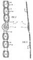
- Fig. 1is a perspective view of a knee brace assembly as disclosed in US-A-2005/.
- Fig. 2is a plan view of one of the two knee braces included in the knee brace assembly of Fig. 1 ;
- Fig. 3is a side view of the knee brace of Fig. 2 ;
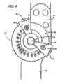
- Fig. 4is an enlarged plan view of a knee brace pivot and motion limiting assembly
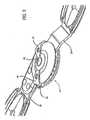
- Fig. 5is an enlarged perspective view of the pivot assembly
- Fig. 6is an exploded view of the knee brace assembly
- Fig. 7is an enlarged view of the central pivot and stop assembly of the knee brace of Figs. 1-6 , with the front cover removed;
- Fig. 8is an exploded view of the two movable stops and their associated adjustment buttons, and indication support members;
- Figs. 9-12show various stop adjustment configurations for the knee brace
- Fig. 13is an exploded perspective view of an alternative embodiment knee brace assembly according to the invention.
- Fig. 13ais a cross-sectional view showing the interaction of the detent and the adjustment hole of the strut extension.
- Fig. 14is an exploded perspective view of the hinge assembly for the knee brace shown in Fig. 13 .
- Fig. 1shows a leg brace 12 for the knee, including two struts extending up and down the leg from a central pivot assembly 14. Extending along the upper leg is a strut 16, and extending down the lower leg from the pivot assembly 14 is a lower strut 18. These struts are sometimes referenced as femoral struts (as extending along the femur or upper leg bone) and tibial struts (extending along the tibia, or the principal lower leg bone). A pivot assembly on the other side of the knee is also provided with struts extending up and down the leg, but these are not visible in Fig. 1 .
- a series of straps 22 on the upper leg, and straps 24 on the lower legare a series of straps 22 on the upper leg, and straps 24 on the lower leg.
- Suitable padding 26is provided on the upper leg, and the struts are normally secured to the padding 26 by appropriate VELCRO® or hook and loop type material.
- Similar padding 28underlies the strut 18 and straps 24.
- the straps 22extend through the loops 38 to hold the entire assembly together under active usage conditions.
- Fig. 1The showing of Fig. 1 is of the outside of the left leg. On the inside of the left leg is a similar assembly, to that shown in fig. 1 , with two struts and a central pivot assembly. The two units are similar and both are held to the leg by the straps 22 and 24. Most of the parts are common to the inner and outer assemblies, but with the struts and the cover plates being mirror images of one another.
- strut 18In operation, the two struts 16 and 18 are pivoted relative to one another about center rivet 56; and strut 18 has two stop surfaces 32 and 34. Adjustable stops are mounted to the hinge pivot assembly 14 on strut 16 and the adjustable stops engage stop surfaces 32 and 34 to limit pivoting of the knee in both the extension and the flexion directions.
- Fig. 2 of the drawingsshows the assembly 12 and the pivot assembly 14 with the straps 22 and 24, and the padding 26 and 28 removed. Visible in Fig. 2 are the strap coupling members 36 which are secured to the struts, and the strap receiving openings 38. Fig. 3 is a side view of the assembly of Fig. 2 .
- the central stop mechanism 14will be described in greater detail hereinbelow.
- FIGs. 4 and 5 of the drawingsare plan and perspective views, respectively of the central stop mechanism 14 which interconnects the struts 16 and 18.
- Fig. 4it includes the extension stop assembly 42 and the flexion stop assembly 44. Visible on the cover plate 46 are degree indicia which may be read through the openings 48 and 50 on the stop assemblies 42 and 44, respectively.
- the push buttons 52 and 54are depressed and the stop assemblies are rotated to the desired angular settings.
- the outermost surfaces of push buttons 52 and 54are preferably knurled, ribbed or textured for non-slip engagement.
- the stopsmay be coated with a frictional coating.
- the flexion stop 44when it is set to 120° the lower leg may be fully bent toward the upper leg. When the flexion stop is set to "lock”, then the lower leg is fully extended, and is blocked from any bending. If both stops 42 and 44 are set to 60° for example, the knee is held at 60° from fully open, and is restrained from movement in either direction.
- the support members for the stopsare both pivoted about the center 56 of the pivot assembly 14, with the reference number 56 representing the head of a rivet extending through the assembly.
- one of the two struts 18has the two stop surfaces 32 and 34 on its end, and is pivoted, with opening 62 receiving rivet 56 which extends through the entire assembly.
- the flat parts 64 and 66are spacers and also serve the function of washers in facilitating rotation of the overlying parts. They may be formed of plastic such as nylon.
- the catch plates 68 and 70have a series of inwardly opening recesses which receive outwardly biased locking pins as described below.
- the inner cover plate 72 and the outer cover plate 74may also be provided with inwardly directed recesses, matching those in the catch plates 68 and 70. This provides supplemental restraint for the locking pins shown in detail in later figures of the drawings.
- Fig. 7is an enlarged view of the central mechanism with one of the cover plates removed.
- the stop assembly 44has a locking pin 82 which moves inward with the push button 54 to change settings, but is spring biased outward to engage one of the recesses 84.
- the locking pin 86 associated with push button 52locks the stop 42 by engagement with a selected one of the catch plate recesses 84.
- Fig. 8is an enlarged showing of the physical stop members 92 and 94 which engage the stop surfaces 32 and 34 as shown in fig. 6 .
- Two small pairs of coil springs 96 and 98serve to bias the push buttons 52 and 54, and the associated locking pins 86 and 82 outward, into engagement with the catch plate 68 (see Fig. 7 ) and the other catch plate 70 (see Fig. 6 ).
- the physical stops 92 and 94may be formed of a high strength zinc alloy referenced as ZA-28, or other high strength material.
- Figs. 9 through 12shows various adjustments of the stops, and the resultant permitted positions of the struts 16 and 18. More specifically, Fig. 9 shows the extension stop 42 and the flexion stop 44 in their positions for full range of motion, with the extension stop 42 at 0° and the extension stop 44 at 120° (see Fig. 4 ). In Fig. 9 the struts (and the leg) are fully extended; while in Fig. 10 , the struts and the leg are bent to their extreme flexed position, with the two stops in the same positions for both Fig. 9 and Fig. 10 .
- Fig. 11is a similar pair of drawings with the extension stop at about 45° and the flexion stop at about 75° in both figures.
- the strutsare extended as far as possible with this setting of stops 42 and 44; and in Fig. 12 the struts (and leg) are bent as far as permitted with this setting of the stops 42 and 44.
- An alternative embodiment of the stop mechanismmay include a physical stop having a radially extending slot for receiving a locking pin associated with a push button; and a wire spring biasing the push button and locking pin radially outward relative to the stop support members.
- the push buttons 52 and their associated assembliesare preferably color coded to match colored angle indicia.
- push button 52may be colored blue, with the associated degree indicia from “0" to "90" degrees being the same blue color; and push button 54 and associated indicia may be colored green.
- the push buttonsare provided with holes near the outer ends thereof. This permits the physician or technical assistant to thread wire or plastic ties through the openings to discourage re-setting or tampering with the angular settings, as shown at reference numerals 101 and 103 in Figs. 11 and 12 of the drawings.
- Other elements for preventing or restricting actuation of the push buttons, including locking ties,may be employed; and these elements may be separate from or integral with and movable with respect to, the knee brace assembly.
- Fig. 13is an exploded perspective viewed of an ergonomic knee brace according to the invention, having extendable struts 100 for convenient length adjustments.
- an upper (femoral) strut assembly 102is joined to a hinge assembly or pivoting arrangement 104.
- a lower (tibial) strut assembly 106is also joined to the hinge assembly 104.
- Each strut assembly 102, 106is preferably riveted at one end to the hinge assembly 104 via one or more rivets 108 and respective washers and/or lock nuts 110.
- Other mechanical fasteners or linkagesmay be used to join the components as well as the use of adhesives, welding, brazing, or the like.
- Each strut assembly 102, 106includes a strut sleeve 112, 114.
- the strut sleeve 112, 114is preferably made from a molded plastic having a generally rectangular cross-section with a rectangular channel, slot, or hole 166 extending through the center.
- the rectangular hole 166 of the strut sleeves 112, 114is designed to slidably receive respective strut extensions 116, 118.
- Each strut extension 116, 118is preferably made from a rigid material such as steel and includes a series of spaced apart length-adjustment holes 120.
- the preferred elongated flat plate shape of the strut extensions 116, 118allows the extensions to easily slide in and out of the respective strut sleeves 112, 114 thereby adjusting the overall lengths of the upper and lower strut assemblies 102, 106.
- markingssuch as numerals, hash marks, and other indicia can be placed on the strut extensions 116, 118 to guide and assist in repeatably and quickly setting up the desired length of the strut assemblies 102, 106.
- a screw-in knob or lock level 122is turned preferably 180° clockwise manually to lock the strut extension 116, 118 to the respective sleeve 112, 114 thus inhibiting further relative sliding.
- the screw-in knob or lock lever 122includes a post 124 extending underneath having threads thereon that engage threads in the sleeve 112, 114 and that advance the post 124 into one of the adjustment/receiving holes 120 of the respective strut extension 116, 118. This is shown in the cross-sectional view of Fig. 13a .
- the screw-in lever 122preferably has a low profile, elongated lever-like shape so that via manual twisting action by the user, sufficient torque is generated to advance the post 124 into the respective strut extension adjustment hole 120.
- a low profileprevents inadvertent operation of the screw-in lever 122 by accidental brushing against clothing, the wearer's limb, or furniture, for example.
- the upper surface of the lever 122may be textured.
- the screw-in lever 122 and strut sleeves 112, 114are preferably made from glass filled nylon or like polymers.
- the strut sleevesmay have an aluminum, steel, or like metal skeleton over which the plastic is molded if more strength is desired.
- the adjustment holes 120 of the strut extensions 116, 118are covered by the strut sleeves 112, 114 when the two parts are assembled, the user or wearer is not able to easily align the post 124 with the desired adjustment hole 120 to interlock the sleeve and extension together.
- the preferred embodiment strut sleeve 112, 114has one or more detents 126 formed into the interior surface at the bottom of the rectangular opening 166. This is shown in the cross-sectional view in Fig. 13a .
- the detent 126is a bump, ridge, ramp, or like click-stop that slightly enters and easily slides out of any one of the adjustment holes 120 of the strut extension 116, 118.
- the detent 126is formed from the material used to create the strut sleeve 112, 114, and more preferably, the detent 126 is a partial cutout of the sleeve bottom to form a cantilevered spring configuration shown in Fig. 13a .
- the detent 126is an inward facing bump positioned at the end of an elongated, rectangular spring board whose shape is defined by three-quarters peripheral cut with a base still attached to the sleeve 112, 114.
- This cantilevered spring configuration for the detent 126creates even greater vertical compliance allowing the bump of the detent 126 to engage and disengage the adjustment hole 120 for improved tactile and audible indications yet does not significantly impede the strut extension sliding action inside the strut sleeve 112, 114.
- One or more detents 126may be used in each sleeve and/or for each hole.
- an optional turn stop 172 positioned on the surface of the sleeve 112, 114blocks the outer limit of rotational travel of the screw-in lever 122.
- Figs. 13 and 13ashow such a stop 172.
- the preferred embodiment turn stop 172has a ramp-like profile with a flat engagement face that is designed to engage the rotating screw-in lever 122.
- the screw-in lever 122can be rotated clockwise through about 270° and more preferably about 180° of travel until encountering the rising resistance of moving up the ramp of the turn stop 172, and the screw-in lever 122 can be rotated about 270° and more preferably about 180° counterclockwise until it encounters the flat engagement face at the opposite side of the turn stop 172.
- the pitch of the threads for the post 124is selected so that about a 270° and more preferably about 180° clockwise turn is sufficient to fully engage the post 124 with the adjustment hole 120.
- smaller or larger angular turns of the screw-in lever 122 to lock and unlock the componentsare contemplated.
- the preferred 180° rotational range to lock/unlock the screw-in lever 122is selected for ergonomics and ease of use of the knee brace wearer.
- curled cuffs 128optionally having laterally extending D-rings can be mounted, fastened, molded, or glued to the strut assemblies 102, 106.
- a single cuff 128is fastened to the very distal end of the upper strut extension 116, and likewise a cuff 128 is attached to the distal end of the lower strut extension 118.
- the upper strut sleeve 112includes two cuffs 128 molded integrally with the sleeve while the lower strut sleeve 114 has a cuff 128 molded integrally with the sleeve with a second cuff that can be attached thereto.
- Adjustable straps(not shown) with VELCRO® fasteners, buckles, and the like can then be looped through the D-rings of the cuffs 128.
- the strapsare used to attach the knee brace to the patient's leg.
- the large surface area of the cuffs 128helps with fitment of the ergonomic knee brace 100 to the patient's leg and minimizes shifting of the leg within the knee brace.
- a gastrocnemius strap 168 with a snap 170 at one endis provided with the knee brace 100.
- the snap 170selectively attaches the gastrocnemius strap 168 to an eyelet or blind hole in the strut sleeve 112, and more precisely to the superior or calf cuff 128'.
- the strap 168When attached to the strut sleeve 112, the strap 168 is worn around the calf area of the patient's leg and helps suspend the knee brace 100 to the leg.
- the knee brace shown in Fig. 13further includes a drop lock feature that can quickly and easily lock down the relative pivoting motions of the upper and lower strut assemblies 102, 106.
- a sliding drop lock button 130is preferably located on the hinge assembly 104 that when slid into its locking position, it interlocks the upper and lower strut assemblies 102, 106 to inhibit the pivoting action.
- the lower strut sleeve 114optionally has a sloped face 132 opposite to the location of the drop lock button 130, essentially on opposite sides of the hinge assembly 104.
- This arrangementprovides a sloped face 132 with flexion angle markings that are visible to the wearer of the knee brace or to a nurse when he or she looks downward on the knee brace 100 when locking down the pivoting action with the drop lock button 130.
- the hinge assembly 104includes a flexion stop 134 and an extension stop 136 that sweep about the hinge assembly 104.
- the upper and lower strut assemblies 102, 106are free to pivot within the defined angular limits set by the flexion and extension stops 134, 136.
- the pivoting-action-lockout via the drop lock button 130 and the flexion and extension stops 134, 136are all centrally congregated at the hinge assembly 104.
- Fig. 14is an exploded perspective view of the hinge assembly 104 from the alternative embodiment knee brace shown in Fig. 13 .
- the principle of operation of the flexion and extension stops 134, 136are as described in the preceding embodiments.
- the hinge assembly 104is a collection of preferably two disk-like catch plates 138, 140.
- Each catch plate 138, 140has a series of recesses or teeth 154 located at the outer periphery of circumferentially extending, arcuate-shaped slots.
- the catch plates 138, 140are mounted to the proximal ends of the lower strut assembly 106 and the upper strut assembly 102.
- the remaining structures of the respective strut assemblieshave been omitted from Fig.
- Both proximal ends of the lower strut assembly 106 and the upper strut assembly 102freely pivot against each other.
- the internal workings of the hinge assembly 104are enclosed by an outer cover plate 142 and an inner cover plate 144.
- the flexion stop 134 and the extension stop 136are mounted to the hinge assembly 104, and each extension or flexion stop 134, 136 has a stop release button 146 that is biased by a spring 152 away from a stop base 148 wherein a lock pin 150 extending through the stop base 148 selectively engages to the teeth 154 formed in the catch plates 138, 140.
- the lock pin 150By pushing radially inward on the extension or flexion stop release button 146 against the bias of the spring 152, the lock pin 150 is disengaged from the teeth 154 allowing the extension or flexion stop base 148 to be moved along the circumferential slots formed in the catch plates 138, 140. This movement enables adjustment the flexion or extension stop angles. Once the finger pressure is released from the extension or flexion stop release button 146, the spring bias forces the lock pins 150 radially outward to again engage the teeth 154 in the catch plates 138, 140.
- a center rivet 156acts as a hub for the hinge assembly 104 and holds the entire assembly together.
- Fig. 14also shows the preferred construction of the drop lock button 130 that is slidably mounted to the surface of the outer cover plate 142.
- the drop lock button 130engages a drop lock base 158 which is held in place by a horseshoe shaped spring 160, which components are then fit into the upper strut assembly 102 as shown.
- One or more ribs 162extend from the drop lock base 158.
- the ribs 162selectively engage one or more stop recesses or teeth 164 formed at the proximal end of the lower strut assembly 106.
- the drop lock base 158moves toward or away from the teeth 164 thereby engaging or disengaging the ribs 162 with the teeth 164.
- the engage between ribs 162 and teeth 164interlocks the lower strut assembly 106 to the upper strut assembly 102 thereby inhibiting the relative pivoting action of the two components.
- the horseshoe spring 160pinches on the drop lock base 158 to provide some bias to hold the drop lock base 158 in either the engaged or disengaged positions.
Landscapes
- Health & Medical Sciences (AREA)
- Nursing (AREA)
- Orthopedic Medicine & Surgery (AREA)
- Engineering & Computer Science (AREA)
- Biomedical Technology (AREA)
- Heart & Thoracic Surgery (AREA)
- Vascular Medicine (AREA)
- Life Sciences & Earth Sciences (AREA)
- Animal Behavior & Ethology (AREA)
- General Health & Medical Sciences (AREA)
- Public Health (AREA)
- Veterinary Medicine (AREA)
- Prostheses (AREA)
- Orthopedics, Nursing, And Contraception (AREA)
Description
- This invention relates to ergonomic knee braces.
- In the field of adjustable knee braces or supports, it is desirable that the brace include arrangements for limiting the movement of the lower leg relative to the upper leg both as to bending the knee or flexion, and as to extension of the lower leg relative to the upper leg. Various knee brace arrangements have been proposed, and these have included upper struts for extending along the thigh, and lower struts for extending along the lower leg or calf. These are normally provided both on the inside or medial side of the leg and also on the outer or lateral side of the leg; and the medial and lateral struts are normally padded, and provided with straps to hold them in place. Pivoting arrangements are provided for coupling the upper and lower struts, and stops are provided for limiting both extension and flexion of the knee.
- The prior art patents in the filed of knee braces include
U.S. Pat. No. 5,672,152 granted September 30, 1997 ;U.S. Pat. No. 5,921,946, granted July 13, 1999 ;U.S. Pat. No. 4,817,588, granted April 14, 1989 ,U.S. Pat. No. 4,953,543 granted September 4, 1990 , andU.S. Pat. No. 4,620,532 granted November 4, 1986 . Although many of the foregoing provided useful results, these prior art knee braces had shortcomings, in that they were unduly bulky, or were not simple to adjust, or did not have as many stop increments as would be desired, or were otherwise not ergonomically configured. U.S. patent application publication 2005/0070831 describes an adjustable ergonomic knee brace having a hinge with push button actuatable stops that are outwardly biased into angular locking positions. While the knee brace has a hinge allowing for angular locking positions, it does not provide any description on adjusting the hight of the strut assemblies used to secure the brace on the leg.- Accordingly, objects of the invention include providing a knee brace which is compact, easy to use, which has many points of adjustment and is otherwise ergonomically configured. Preferably the adjustments should be simple and natural so that there is no need to resort to collateral written instructions.
- Initially, relative to an illustrative preferred embodiment of the present knee brace, the knee brace stop construction operates at the periphery of the pivot arrangmenets so that the number of stop increments is maximized for the size of the pivot discs. Secondly, the stops may be operated by simple inward pressure on a push button associated with the flexion stop or the extension stop, to release the stop, followed by rotation of the stop to virtually any desired angle, and then followed by release of the push button to permit locking of the stop in the new angular position. With this simplified ergonomic construction, the stop adjustments may be easily made while the brace is mounted on the leg; and the mode of accomplishing stop adjustments is substantially self evident, with the shifting of the stops resulting in the natural or expected angular change in flexion or extension stops.
- In order to achieve the foregoing results in one illustrative embodiment, the pivoting assembly interconnecting the upper and lower struts includes, for both extension and flexion, at least one generally circular or arcuate catch plate with stop recesses facing or opening inward toward the center of the assembly, and a movable stop member pivoted at the center of the assembly and having an outwardly biased locking member for selectively engaging one of the stop recesses, and with the locking member attached to a release button which extends radially outward to the periphery of the pivot assembly.
- Viewed from a different aspect, the pivoting assembly may include an outer cover or closure plate and an inner cover or closure plate; an arcuately configured array of locking steps; a movable stop member pivoted at the center of the assembly and having an outwardly biased locking member for selectively engaging at least one of the locking steps; and with the locking member attached to a release button which is located radially outward at the periphery of the pivot assembly.
- Additional features may include the provision of angular indicia on the outer surface of the outer one of said cover or closure plates and the implementation of the movable stop assembly by an outer, radially extending flat support member adjacent the indicia, preferably with a window through which the angular indicia may be seen. Further, the movable stop assembly may extend over the edge of one of said plates into the space between the two cover plates to cooperate with the locking steps. This construction contributes to the relatively thin overall configuration of the pivoting assembly, which may be only about one-half inch or about 1.3 cm thick. Also, to provide adequate strength and compactness, the brace and it components are preferably made of high strength material such as steel, titanium, zinc alloys, or other high strength metals or high strength plastic.
- It is further noted that, in the preferred design, two catch plates are provided, and each of the stop assemblies includes a pin which seats in corresponding recesses in each of the two catch plates, to provide a balanced locking configuration for resisting forces applied between the struts to limit flexion or extension. The inner and outer cover plates may also have complementary recesses to more positively secure the stops at the selected angular position.
- Referring back to the overall construction as mentioned above, one strut extends from the knee pivot assembly up the upper leg or thigh, and the other strut extends from the pivot assembly down the lower leg. The pivot stop assembly is mounted on the end of a first one of these struts, and the second strut has stop surfaces on its end adjacent the stop assembly which engage the flexion and extension stops. Further, the catch plates as described above are mounted on opposite sides of this second strut, with the locking member of the movable stop assembly engaging locking steps on both of the two catch plates, so that a balanced positive stopping force is transmitted to the second strut when the stop surfaces on the end of the second strut engage the flexion stop or the extension stop.
- Additional aspects of the knee brace may include the following:
- (1) catch plates which have separate sets of notches for the flexion and extension stops, and a mechanical coupling between these two sets of notches;
- (2) Color coded flexion and extension actuation buttons, with the degree indicia set forth in matching different colors;
- (3) Apertures or holes in the actuation buttons to permit locking of the buttons against change.
- Other objects, features and advantages of the invention will become apparent from a consideration of the drawings and from the detailed description.
Fig. 1 is a perspective view of a knee brace assembly as disclosed in US-A-2005/.Fig. 2 is a plan view of one of the two knee braces included in the knee brace assembly ofFig. 1 ;Fig. 3 is a side view of the knee brace ofFig. 2 ;Fig. 4 is an enlarged plan view of a knee brace pivot and motion limiting assembly;Fig. 5 is an enlarged perspective view of the pivot assembly;Fig. 6 is an exploded view of the knee brace assembly ;Fig. 7 is an enlarged view of the central pivot and stop assembly of the knee brace ofFigs. 1-6 , with the front cover removed;Fig. 8 is an exploded view of the two movable stops and their associated adjustment buttons, and indication support members;Figs. 9-12 show various stop adjustment configurations for the knee brace;Fig. 13 is an exploded perspective view of an alternative embodiment knee brace assembly according to the invention;Fig. 13a is a cross-sectional view showing the interaction of the detent and the adjustment hole of the strut extension; andFig. 14 is an exploded perspective view of the hinge assembly for the knee brace shown inFig. 13 .- While the specification describes particular embodiments of the present invention, those of ordinary skill can devise variations of the present invention without departing from the inventive concept.
- Referring more particularly to the drawings,
Fig. 1 shows aleg brace 12 for the knee, including two struts extending up and down the leg from acentral pivot assembly 14. Extending along the upper leg is astrut 16, and extending down the lower leg from thepivot assembly 14 is alower strut 18. These struts are sometimes referenced as femoral struts (as extending along the femur or upper leg bone) and tibial struts (extending along the tibia, or the principal lower leg bone). A pivot assembly on the other side of the knee is also provided with struts extending up and down the leg, but these are not visible inFig. 1 . - To hold the struts in place on the leg are a series of
straps 22 on the upper leg, andstraps 24 on the lower leg.Suitable padding 26 is provided on the upper leg, and the struts are normally secured to thepadding 26 by appropriate VELCRO® or hook and loop type material.Similar padding 28 underlies thestrut 18 andstraps 24. Thestraps 22 extend through theloops 38 to hold the entire assembly together under active usage conditions. - For a post-operative patient, it is desirable to be able to limit the bending of the knee both in the extension direction when the patient is straightening his or her leg, and in the flexion direction where the patient is bending the leg at the knee as far as practical under the circumstances.
- The showing of
Fig. 1 is of the outside of the left leg. On the inside of the left leg is a similar assembly, to that shown infig. 1 , with two struts and a central pivot assembly. The two units are similar and both are held to the leg by thestraps - To better understand the operation of the entire assembly, it is useful to refer briefly to the exploded view of
Fig. 6 . In operation, the twostruts center rivet 56; and strut 18 has two stop surfaces 32 and 34. Adjustable stops are mounted to thehinge pivot assembly 14 onstrut 16 and the adjustable stops engage stop surfaces 32 and 34 to limit pivoting of the knee in both the extension and the flexion directions. Fig. 2 of the drawings shows theassembly 12 and thepivot assembly 14 with thestraps padding Fig. 2 are thestrap coupling members 36 which are secured to the struts, and thestrap receiving openings 38.Fig. 3 is a side view of the assembly ofFig. 2 . Thecentral stop mechanism 14 will be described in greater detail hereinbelow.- Referring now to
Figs. 4 and5 of the drawings, these are plan and perspective views, respectively of thecentral stop mechanism 14 which interconnects thestruts - Now, considering
Fig. 4 in detail, it includes theextension stop assembly 42 and theflexion stop assembly 44. Visible on thecover plate 46 are degree indicia which may be read through theopenings stop assemblies push buttons push buttons - Concerning the angular settings, when the
extension stop 42 is at zero degrees (0°), the patient is free to fully extend his lower leg. When theextension stop 42 is set to 90°, the lower leg is restrained from movement beyond 90° relative to the upper leg, so the lower leg cannot be straightened out. - Regarding the
flexion stop 44, when it is set to 120° the lower leg may be fully bent toward the upper leg. When the flexion stop is set to "lock", then the lower leg is fully extended, and is blocked from any bending. If both stops 42 and 44 are set to 60° for example, the knee is held at 60° from fully open, and is restrained from movement in either direction. - Incidentally, the support members for the stops are both pivoted about the
center 56 of thepivot assembly 14, with thereference number 56 representing the head of a rivet extending through the assembly. - Consideration will now be given to the detailed construction of the pivotal stop mechanism, by reference to the exploded view of
Fig. 6 . As mentioned above, one of the twostruts 18 has the two stop surfaces 32 and 34 on its end, and is pivoted, with opening 62 receivingrivet 56 which extends through the entire assembly. Theflat parts catch plates - The
inner cover plate 72 and theouter cover plate 74 may also be provided with inwardly directed recesses, matching those in thecatch plates Fig. 7 is an enlarged view of the central mechanism with one of the cover plates removed. Thestop assembly 44 has a lockingpin 82 which moves inward with thepush button 54 to change settings, but is spring biased outward to engage one of therecesses 84. Similarly, the lockingpin 86 associated withpush button 52, locks thestop 42 by engagement with a selected one of the catch plate recesses 84.Fig. 8 is an enlarged showing of thephysical stop members fig. 6 . Two small pairs ofcoil springs push buttons Fig. 7 ) and the other catch plate 70 (seeFig. 6 ).- Incidentally, the physical stops 92 and 94 may be formed of a high strength zinc alloy referenced as ZA-28, or other high strength material.
Figs. 9 through 12 shows various adjustments of the stops, and the resultant permitted positions of thestruts Fig. 9 shows theextension stop 42 and theflexion stop 44 in their positions for full range of motion, with the extension stop 42 at 0° and the extension stop 44 at 120° (seeFig. 4 ). InFig. 9 the struts (and the leg) are fully extended; while inFig. 10 , the struts and the leg are bent to their extreme flexed position, with the two stops in the same positions for bothFig. 9 and Fig. 10 .Fig. 11 is a similar pair of drawings with the extension stop at about 45° and the flexion stop at about 75° in both figures. InFig. 11 the struts are extended as far as possible with this setting ofstops Fig. 12 the struts (and leg) are bent as far as permitted with this setting of thestops - An alternative embodiment of the stop mechanism may include a physical stop having a radially extending slot for receiving a locking pin associated with a push button; and a wire spring biasing the push button and locking pin radially outward relative to the stop support members.
- Concerning another matter, with reference to
Fig. 4 of the drawings, thepush buttons 52 and their associated assemblies are preferably color coded to match colored angle indicia. Thus,push button 52 may be colored blue, with the associated degree indicia from "0" to "90" degrees being the same blue color; and pushbutton 54 and associated indicia may be colored green. - It may be noted that the push buttons are provided with holes near the outer ends thereof. This permits the physician or technical assistant to thread wire or plastic ties through the openings to discourage re-setting or tampering with the angular settings, as shown at
reference numerals Figs. 11 and 12 of the drawings. Other elements for preventing or restricting actuation of the push buttons, including locking ties, may be employed; and these elements may be separate from or integral with and movable with respect to, the knee brace assembly. Fig. 13 is an exploded perspective viewed of an ergonomic knee brace according to the invention, havingextendable struts 100 for convenient length adjustments. Specifically, in the embodiment shown inFig. 13 , an upper (femoral)strut assembly 102 is joined to a hinge assembly or pivotingarrangement 104. A lower (tibial)strut assembly 106 is also joined to thehinge assembly 104. Eachstrut assembly hinge assembly 104 via one ormore rivets 108 and respective washers and/or lock nuts 110. Other mechanical fasteners or linkages may be used to join the components as well as the use of adhesives, welding, brazing, or the like.- Each
strut assembly strut sleeve strut sleeve hole 166 extending through the center. Therectangular hole 166 of thestrut sleeves respective strut extensions strut extension strut extensions respective strut sleeves lower strut assemblies Fig. 13 , markings such as numerals, hash marks, and other indicia can be placed on thestrut extensions strut assemblies - Once the desired length of the
strut extension lock level 122 is turned preferably 180° clockwise manually to lock thestrut extension respective sleeve lock lever 122 includes apost 124 extending underneath having threads thereon that engage threads in thesleeve post 124 into one of the adjustment/receivingholes 120 of therespective strut extension Fig. 13a . The screw-inlever 122 preferably has a low profile, elongated lever-like shape so that via manual twisting action by the user, sufficient torque is generated to advance thepost 124 into the respective strutextension adjustment hole 120. A low profile prevents inadvertent operation of the screw-inlever 122 by accidental brushing against clothing, the wearer's limb, or furniture, for example. For better grip, the upper surface of thelever 122 may be textured. - To unlock the
strut extension strut sleeve lever 122 withdraws thepost 124 from engagement with thehole 120. The strut extension and its sleeve can now freely slide relative to each other. - To provide sufficient strength, the screw-in
lever 122 and strutsleeves - Because the adjustment holes 120 of the
strut extensions strut sleeves post 124 with the desiredadjustment hole 120 to interlock the sleeve and extension together. To enhance easy alignment of thepost 124 andadjustment hole 120, the preferredembodiment strut sleeve more detents 126 formed into the interior surface at the bottom of therectangular opening 166. This is shown in the cross-sectional view inFig. 13a . - Therefore, as each
adjustment hole 120 slides past thedetent 126, there is noticeable click-stop that can be felt and heard by the user indicating that thepost 124 and one of the adjustment holes 120 are aligned. In the preferred embodiment, thedetent 126 is a bump, ridge, ramp, or like click-stop that slightly enters and easily slides out of any one of the adjustment holes 120 of thestrut extension detent 126 is formed from the material used to create thestrut sleeve detent 126 is a partial cutout of the sleeve bottom to form a cantilevered spring configuration shown inFig. 13a . That is, thedetent 126 is an inward facing bump positioned at the end of an elongated, rectangular spring board whose shape is defined by three-quarters peripheral cut with a base still attached to thesleeve detent 126 creates even greater vertical compliance allowing the bump of thedetent 126 to engage and disengage theadjustment hole 120 for improved tactile and audible indications yet does not significantly impede the strut extension sliding action inside thestrut sleeve more detents 126 may be used in each sleeve and/or for each hole. - To prevent the user from accidentally overly twisting the screw-in
lever 122, an optional turn stop 172 positioned on the surface of thesleeve lever 122.Figs. 13 and13a show such astop 172. The preferred embodiment turn stop 172 has a ramp-like profile with a flat engagement face that is designed to engage the rotating screw-inlever 122. Thus, the screw-inlever 122 as shown inFig. 13 can be rotated clockwise through about 270° and more preferably about 180° of travel until encountering the rising resistance of moving up the ramp of the turn stop 172, and the screw-inlever 122 can be rotated about 270° and more preferably about 180° counterclockwise until it encounters the flat engagement face at the opposite side of the turn stop 172. The pitch of the threads for thepost 124 is selected so that about a 270° and more preferably about 180° clockwise turn is sufficient to fully engage thepost 124 with theadjustment hole 120. Of course, smaller or larger angular turns of the screw-inlever 122 to lock and unlock the components are contemplated. The preferred 180° rotational range to lock/unlock the screw-inlever 122 is selected for ergonomics and ease of use of the knee brace wearer. - An assortment of curled
cuffs 128 optionally having laterally extending D-rings can be mounted, fastened, molded, or glued to thestrut assemblies Fig. 13 , asingle cuff 128 is fastened to the very distal end of theupper strut extension 116, and likewise acuff 128 is attached to the distal end of thelower strut extension 118. Theupper strut sleeve 112 includes twocuffs 128 molded integrally with the sleeve while thelower strut sleeve 114 has acuff 128 molded integrally with the sleeve with a second cuff that can be attached thereto. Adjustable straps (not shown) with VELCRO® fasteners, buckles, and the like can then be looped through the D-rings of thecuffs 128. The straps are used to attach the knee brace to the patient's leg. The large surface area of thecuffs 128 helps with fitment of theergonomic knee brace 100 to the patient's leg and minimizes shifting of the leg within the knee brace. Optionally, agastrocnemius strap 168 with asnap 170 at one end is provided with theknee brace 100. Thesnap 170 selectively attaches thegastrocnemius strap 168 to an eyelet or blind hole in thestrut sleeve 112, and more precisely to the superior or calf cuff 128'. When attached to thestrut sleeve 112, thestrap 168 is worn around the calf area of the patient's leg and helps suspend theknee brace 100 to the leg. - The knee brace shown in
Fig. 13 further includes a drop lock feature that can quickly and easily lock down the relative pivoting motions of the upper andlower strut assemblies drop lock button 130 is preferably located on thehinge assembly 104 that when slid into its locking position, it interlocks the upper andlower strut assemblies - To quickly and repeatably locate the desired flexion angle of the knee when the drop lock can be used, the
lower strut sleeve 114 optionally has a slopedface 132 opposite to the location of thedrop lock button 130, essentially on opposite sides of thehinge assembly 104. This arrangement provides asloped face 132 with flexion angle markings that are visible to the wearer of the knee brace or to a nurse when he or she looks downward on theknee brace 100 when locking down the pivoting action with thedrop lock button 130. As in the previous embodiments, thehinge assembly 104 includes aflexion stop 134 and anextension stop 136 that sweep about thehinge assembly 104. With thedrop lock button 130 disengaged, the upper andlower strut assemblies drop lock button 130 and the flexion and extension stops 134, 136 are all centrally congregated at thehinge assembly 104. Fig. 14 is an exploded perspective view of thehinge assembly 104 from the alternative embodiment knee brace shown inFig. 13 . The principle of operation of the flexion and extension stops 134, 136 are as described in the preceding embodiments. As seen in the exploded view ofFig. 14 , thehinge assembly 104 is a collection of preferably two disk-like catch plates catch plate teeth 154 located at the outer periphery of circumferentially extending, arcuate-shaped slots. Thecatch plates lower strut assembly 106 and theupper strut assembly 102. The remaining structures of the respective strut assemblies have been omitted fromFig. 14 for ease of illustration. Both proximal ends of thelower strut assembly 106 and theupper strut assembly 102 freely pivot against each other. The internal workings of thehinge assembly 104 are enclosed by anouter cover plate 142 and aninner cover plate 144. Theflexion stop 134 and the extension stop 136 are mounted to thehinge assembly 104, and each extension orflexion stop stop release button 146 that is biased by aspring 152 away from astop base 148 wherein alock pin 150 extending through thestop base 148 selectively engages to theteeth 154 formed in thecatch plates stop release button 146 against the bias of thespring 152, thelock pin 150 is disengaged from theteeth 154 allowing the extension orflexion stop base 148 to be moved along the circumferential slots formed in thecatch plates stop release button 146, the spring bias forces the lock pins 150 radially outward to again engage theteeth 154 in thecatch plates center rivet 156 acts as a hub for thehinge assembly 104 and holds the entire assembly together.Fig. 14 also shows the preferred construction of thedrop lock button 130 that is slidably mounted to the surface of theouter cover plate 142. Thedrop lock button 130 engages adrop lock base 158 which is held in place by a horseshoe shapedspring 160, which components are then fit into theupper strut assembly 102 as shown. One ormore ribs 162 extend from thedrop lock base 158. Theribs 162 selectively engage one or more stop recesses orteeth 164 formed at the proximal end of thelower strut assembly 106. Thus, by sliding thedrop lock button 130 radially inward or outward, thedrop lock base 158 moves toward or away from theteeth 164 thereby engaging or disengaging theribs 162 with theteeth 164. If engaged, the engage betweenribs 162 andteeth 164 interlocks thelower strut assembly 106 to theupper strut assembly 102 thereby inhibiting the relative pivoting action of the two components. Thehorseshoe spring 160 pinches on thedrop lock base 158 to provide some bias to hold thedrop lock base 158 in either the engaged or disengaged positions.- It is to be understood that the foregoing detailed description discloses one preferred illustrative embodiment of the invention. Various changes and modifications may be made without departing from the scope of the invention. Thus, by way of example and not of limitation, instead of having catch plates with locking recesses, a series of outwardly extending rods or protrusions may be provided, with the stop buttons having an outwardly biased fork member for engaging the rods and thereby positioning the stop body or stop plate in the desired angular position. In addition, while the disclosed configuration of the stop supports 44 and 48 is preferred, the stop assemblies may be pivotally mounted within the cover plates as well as, or instead of, extending over the outer surface of the outer cover plate. With regard to another matter, the release push button may be integral with the physical stops. Also, the various parts may be replaced by their mechanical equivalents, such as rivets being replaced by threaded fasteners, or the like. Accordingly, the present invention is not limited to the precise embodiments described in detail hereinabove, and shown in the accompanied drawings.
Claims (7)
- An ergonomic brace comprising:a first elongate strut assembly (102);a second elongate strut assembly (106);pivoting arrangements (104) for intercoupling said first strut assembly (102) and said second strut assembly (106); said pivoting arrangements (104) having a center; andsaid pivoting arrangements (104) including stop assemblies (134, 136) both for flexion and extension, including;(a) a catch plate (138, 140) formed of a flat arcuate disc having an arcuate opening (154) and having stop recesses facing or opening toward the center of said pivoting arrangements (104);(b) a movable stop (134) pivoted at the center of the assembly and having an outwardly biased locking member (148) for engaging said stop recesses (154), coupled to a release button (146) which extends radially outward to the periphery of said pivoting arrangements (104); and(c) said release button (146) being movable inward to shift said locking member (148) out of said stop recesses (154) to permit angular adjustment of said stop (134);at least one of said strut assemblies (102, 106) having an extension stop surface for engaging the extension stop assembly;at least one of said struts assemblies (102, 106) having a flexion stop surface for engaging the flexion stop assembly; andcharacterized in that each strut assembly (102, 106) includes a strut sleeve (112. 114) and an extension (116, 118) slidably engaging the strut sleeve (112, 114), wherein the extension (116, 118) includes a screw-in lock (122) including a rotating lever (122) having a threaded post (124) screwed to respective threads in the strut sleeve (112, 114) and engaging one of a plurality of receiving holes (120) of the extension (116, 118) , said strut sleeve (112, 114) at a location opposite to the screw-in lock (122) includes a detent (126) engaging at least one of the receiving holes (120).
- An ergonomic brace of claim 1, wherein said strut sleeve (112, 114) includes a resilient polymer material, and said detent (126) is formed from a partially cut out portion of the resilient polymer material.
- An ergonomic brace of claim 1, wherein said strut sleeve (112, 114) includes a ramped turn stop (172) selectively engaging the lever (122).
- An ergonomic brace of claim 1, wherein said strut sleeve (112. 114) includes a curved cuff having at least one D-ring (128).
- An ergonomic brace of claim 1, wherein said first strut assembly 102 includes a looped, gastrocnemius strap (168) detachably engaging said strut sleeve (112).
- An ergonomic brace of claim 1, wherein an end of at least one of said first and second strut sleeves (112, 114) near the center of the pivoting arrangements (104) includes a sloped face having markings.
- An ergonomic brace of claim 1, wherein said pivoting arrangements (104) further comprises a drop lock (130) disposed thereon and having a rib (162) slidably engaging at least one stop recess (164) of said first or second strut assemblies (102, 106).
Applications Claiming Priority (2)
| Application Number | Priority Date | Filing Date | Title |
|---|---|---|---|
| US11/384,630US7534220B2 (en) | 2003-09-29 | 2006-03-20 | Adjustable ergonomic brace |
| PCT/US2007/006594WO2007109112A2 (en) | 2006-03-20 | 2007-03-16 | Adjustable ergonomic brace |
Publications (3)
| Publication Number | Publication Date |
|---|---|
| EP1996133A2 EP1996133A2 (en) | 2008-12-03 |
| EP1996133A4 EP1996133A4 (en) | 2010-04-28 |
| EP1996133B1true EP1996133B1 (en) | 2013-04-17 |
Family
ID=38522960
Family Applications (1)
| Application Number | Title | Priority Date | Filing Date |
|---|---|---|---|
| EP07753237.2ANot-in-forceEP1996133B1 (en) | 2006-03-20 | 2007-03-16 | Adjustable ergonomic brace |
Country Status (4)
| Country | Link |
|---|---|
| US (2) | US7534220B2 (en) |
| EP (1) | EP1996133B1 (en) |
| CN (1) | CN101404961B (en) |
| WO (1) | WO2007109112A2 (en) |
Families Citing this family (68)
| Publication number | Priority date | Publication date | Assignee | Title |
|---|---|---|---|---|
| US20040064195A1 (en) | 2002-07-15 | 2004-04-01 | Hugh Herr | Variable-mechanical-impedance artificial legs |
| US8075633B2 (en) | 2003-09-25 | 2011-12-13 | Massachusetts Institute Of Technology | Active ankle foot orthosis |
| US20070123997A1 (en) | 2005-03-31 | 2007-05-31 | Massachusetts Institute Of Technology | Exoskeletons for running and walking |
| US8512415B2 (en) | 2005-03-31 | 2013-08-20 | Massachusetts Institute Of Technology | Powered ankle-foot prothesis |
| US10307272B2 (en) | 2005-03-31 | 2019-06-04 | Massachusetts Institute Of Technology | Method for using a model-based controller for a robotic leg |
| US8500823B2 (en) | 2005-03-31 | 2013-08-06 | Massachusetts Institute Of Technology | Powered artificial knee with agonist-antagonist actuation |
| US10080672B2 (en) | 2005-03-31 | 2018-09-25 | Bionx Medical Technologies, Inc. | Hybrid terrain-adaptive lower-extremity systems |
| US20070162152A1 (en) | 2005-03-31 | 2007-07-12 | Massachusetts Institute Of Technology | Artificial joints using agonist-antagonist actuators |
| US11278433B2 (en) | 2005-03-31 | 2022-03-22 | Massachusetts Institute Of Technology | Powered ankle-foot prosthesis |
| US8864846B2 (en) | 2005-03-31 | 2014-10-21 | Massachusetts Institute Of Technology | Model-based neuromechanical controller for a robotic leg |
| US20060249315A1 (en) | 2005-03-31 | 2006-11-09 | Massachusetts Institute Of Technology | Artificial human limbs and joints employing actuators, springs, and variable-damper elements |
| US20070043449A1 (en) | 2005-03-31 | 2007-02-22 | Massachusetts Institute Of Technology | Artificial ankle-foot system with spring, variable-damping, and series-elastic actuator components |
| US8979780B2 (en)* | 2007-09-14 | 2015-03-17 | Gene C. CHENG | Adjustable immobilizing joint brace |
| US10842653B2 (en) | 2007-09-19 | 2020-11-24 | Ability Dynamics, Llc | Vacuum system for a prosthetic foot |
| US8308671B2 (en)* | 2008-08-28 | 2012-11-13 | Nace Richard A | Knee orthosis |
| US20110082566A1 (en) | 2008-09-04 | 2011-04-07 | Herr Hugh M | Implementing a stand-up sequence using a lower-extremity prosthesis or orthosis |
| KR20110074520A (en) | 2008-09-04 | 2011-06-30 | 아이워크, 아이엔씨. | Hybrid Terrain-Adaptive Prosthetic Systems |
| ES2320307B1 (en)* | 2008-12-12 | 2010-07-07 | Sellex S.A. | TABLE FRAME. |
| US7988653B2 (en)* | 2009-01-08 | 2011-08-02 | Breg, Inc. | Orthopedic elbow brace having a length-adjustable support assembly |
| US8123710B2 (en)* | 2009-07-13 | 2012-02-28 | Shu-Chen Chan | Limiting connector for knee brace |
| CN102892388A (en) | 2010-04-05 | 2013-01-23 | Iwalk股份有限公司 | Controlling torque in a prosthesis or orthosis |
| US8753301B2 (en) | 2010-06-11 | 2014-06-17 | Phong Tran | Adjustable resistance joint brace |
| US8657767B2 (en)* | 2010-06-22 | 2014-02-25 | Shu-Chen Chan | Adjustable orthopedic boot |
| US9180038B2 (en) | 2010-08-05 | 2015-11-10 | Ossur Hf | Walker having height adjustment and method for doing the same |
| GB201018749D0 (en)* | 2010-11-08 | 2010-12-22 | C Pro Direct Ltd | Ankle foot orthopaedic devices |
| DE102010053176A1 (en)* | 2010-12-03 | 2012-06-06 | Otto Bock Healthcare Gmbh | adjustment |
| WO2012096956A1 (en) | 2011-01-10 | 2012-07-19 | Iwalk, Inc. | Powered joint orthosis |
| US20120259430A1 (en) | 2011-01-12 | 2012-10-11 | Zhixiu Han | Controlling powered human augmentation devices |
| US9687377B2 (en) | 2011-01-21 | 2017-06-27 | Bionx Medical Technologies, Inc. | Terrain adaptive powered joint orthosis |
| WO2012125562A1 (en) | 2011-03-11 | 2012-09-20 | Iwalk, Inc. | Biomimetic joint actuators |
| ITGO20110003A1 (en) | 2011-03-30 | 2012-10-01 | Jacqueline Pellis | KNEE ASSESSMENT DEVICE AND ITS RESPECTOR |
| US9622900B2 (en) | 2011-09-16 | 2017-04-18 | Townsend Industries, Inc. | Knee brace with tool less length adjuster |
| WO2013067407A1 (en) | 2011-11-02 | 2013-05-10 | Iwalk, Inc. | Biomimetic transfemoral prosthesis |
| US9032635B2 (en) | 2011-12-15 | 2015-05-19 | Massachusetts Institute Of Technology | Physiological measurement device or wearable device interface simulator and method of use |
| LT2793794T (en)* | 2011-12-20 | 2022-12-12 | iWALKFREE, INC. | Hands-free crutch |
| US9271860B2 (en) | 2012-03-20 | 2016-03-01 | Ossur Hf | Orthopedic device |
| US9925082B2 (en)* | 2012-03-20 | 2018-03-27 | Ossur Hf | Orthopedic device |
| US9221177B2 (en) | 2012-04-18 | 2015-12-29 | Massachusetts Institute Of Technology | Neuromuscular model-based sensing and control paradigm for a robotic leg |
| WO2013188510A2 (en) | 2012-06-12 | 2013-12-19 | Iwalk, Inc. | Prosthetic, orthotic or exoskeleton device |
| USD693930S1 (en) | 2012-07-12 | 2013-11-19 | Ossur Hf | Pair of struts for an orthopedic device |
| US10524948B2 (en) | 2013-01-22 | 2020-01-07 | Orthocare Medical Equipment, Llc | Micro-adjustable telescoping arms for orthopedic braces |
| ITRM20130100A1 (en)* | 2013-02-21 | 2014-08-22 | Tecnoway S A S | TUTOR FOR JOINT. |
| CN105307603B (en)* | 2013-03-15 | 2017-12-19 | 汤森工业公司D/B/A/ 汤森设计公司 | Dynamic force hinge joint for knee brace and knee brace equipped with the dynamic force hinge joint |
| TWM470659U (en)* | 2013-10-03 | 2014-01-21 | ming-jie Lv | Angle-adjustable rehabilitation device |
| US20150100006A1 (en)* | 2013-10-03 | 2015-04-09 | Ming-Chieh Lu | Angle-adjustable rehabilitation device |
| TWI531352B (en)* | 2013-11-19 | 2016-05-01 | Plus Meditech Co Ltd | Hinged orthosis |
| WO2016007496A1 (en)* | 2014-07-10 | 2016-01-14 | Ossur Hf | Versatile orthopedic device |
| EP3283020B1 (en)* | 2015-04-17 | 2020-06-03 | Vision Quest Industries Incorporated Dba VQ Orthocare | Orthotic device with snap fit cuff and latch mechanism |
| US9993362B2 (en) | 2015-06-30 | 2018-06-12 | Deroyal Global Healthcare Solutions Limited | Adjustable knee brace |
| US10188539B2 (en)* | 2015-10-05 | 2019-01-29 | SpringLoaded Technology Incorporated | Stabilizing system for a knee brace |
| CN105459145B (en)* | 2015-12-14 | 2017-11-10 | 天津理工大学 | External flexible knee joint |
| WO2017176680A1 (en)* | 2016-04-04 | 2017-10-12 | Ossur Iceland Ehf | Orthopedic device |
| US10427023B2 (en)* | 2016-04-15 | 2019-10-01 | Bsn Sports, Llc | Shoulder pads and method of manufacturing the same |
| CN106073966B (en)* | 2016-08-26 | 2019-12-17 | 上海高博医疗器械有限公司 | Orthopedic ware of bone joint |
| US10117769B2 (en) | 2016-08-31 | 2018-11-06 | Jay C. Humphrey | Orthopedic knee brace |
| US20180110643A1 (en)* | 2016-10-24 | 2018-04-26 | Curtis Bryan Carlson | Hinged Wrist and Hand Support |
| USD835289S1 (en) | 2016-11-08 | 2018-12-04 | Ossur Iceland Ehf | Orthopedic device |
| USD813089S1 (en) | 2016-11-08 | 2018-03-20 | Ossur Iceland Ehf | D-ring |
| US10702410B2 (en)* | 2017-04-14 | 2020-07-07 | Meng-Chun Wang | Joint angle adjustment mechanism |
| CN109998754B (en)* | 2018-05-02 | 2024-08-30 | 玛瑜科创服务(南京)有限公司 | Knee joint orthosis |
| DE102018207727A1 (en)* | 2018-05-17 | 2019-11-21 | Bauerfeind Ag | Stabilizing bar for an orthopedic aid |
| CN109259921B (en)* | 2018-11-29 | 2021-07-20 | 厦门杰斯医疗器械有限公司 | Adjustable joint protection brace with self-locking function |
| CN113194889B (en) | 2018-12-20 | 2024-02-13 | Djo有限责任公司 | Braces that limit range of motion and how to use them |
| CN110421592A (en)* | 2019-09-03 | 2019-11-08 | 江苏集萃微纳自动化系统与装备技术研究所有限公司 | A kind of knee-joint mechanism for wearable ectoskeleton |
| CN111012626A (en)* | 2019-12-30 | 2020-04-17 | 中航创世机器人(西安)有限公司 | Upper limb rehabilitation robot system based on multi-dimensional force feedback |
| CN111700776B (en)* | 2020-06-22 | 2022-01-04 | 苏州市职业大学 | Auxiliary walker based on hybrid drive of worm gear motor and energy storage spring |
| CN114176863B (en)* | 2021-12-31 | 2023-08-18 | 中南大学湘雅医院 | Tibia correction device for treating knee osteoarthritis varus and valgus deformity |
| WO2025165818A1 (en) | 2024-01-31 | 2025-08-07 | Ossur Iceland Ehf | Orthopedic device having a lock mechanism |
Family Cites Families (45)
| Publication number | Priority date | Publication date | Assignee | Title |
|---|---|---|---|---|
| US401933A (en) | 1889-04-23 | Fracture apparatus | ||
| US1366800A (en)* | 1919-07-23 | 1921-01-25 | Zerah G Hayden | Combination-rule and adjustable compass |
| US2470344A (en)* | 1945-07-21 | 1949-05-17 | Dzus William | Fastener |
| US2632440A (en) | 1947-12-17 | 1953-03-24 | John M Hauser | Leg brace joint and lock |
| CA986811A (en)* | 1971-10-21 | 1976-04-06 | Klaus Thur | Telescopic umbrella stick |
| US4239139A (en)* | 1979-02-05 | 1980-12-16 | Bott John Anthony | Sliding tie down vehicle luggage carrier |
| US4520804A (en) | 1981-08-04 | 1985-06-04 | Digeorge Michael A | Double-locking ratchet for orthopedic brace |
| US4481941A (en) | 1983-03-07 | 1984-11-13 | Rolfes Thomas A | Universal hip stabilization device |
| US4620532A (en) | 1983-09-26 | 1986-11-04 | Lenox Hill Brace Shop, Inc. | Adjustment device for an articulated joint brace |
| US4576151A (en) | 1984-03-19 | 1986-03-18 | Carmichael Hoagy C | Orthopedic leg appliance |
| US4886054A (en) | 1987-06-29 | 1989-12-12 | Innovation Sports, Inc. | Knee brace with cammed stop lever |
| US4817588A (en) | 1987-07-01 | 1989-04-04 | Medical Technology, Inc. | Motion restraining knee brace |
| US4953543A (en) | 1988-08-09 | 1990-09-04 | Royce Medical Company | Cruciate ligament leg brace |
| US5000169A (en) | 1990-01-16 | 1991-03-19 | Clinitex Corporation | Adjustable flexion-extension hinge for hinged limb immobilizer |
| US4982732A (en) | 1990-02-06 | 1991-01-08 | Orthopedic Technology, Inc. | Orthopedic rehabilitation knee brace |
| US5135469A (en) | 1991-05-02 | 1992-08-04 | Innovation Sports, Inc. | Post-surgical knee brace with incremental adjustment |
| ATE124621T1 (en)* | 1992-04-29 | 1995-07-15 | Bock Orthopaed Ind | KNEE BORTHESIS. |
| DE4238387B4 (en) | 1992-11-13 | 2004-02-26 | Heidelberger Druckmaschinen Ag | Sheeter for material webs with a control device for the cutting register |
| US5437619A (en)* | 1993-06-30 | 1995-08-01 | Empi, Inc. | Range-of-motion splint with eccentric spring |
| US5571078A (en) | 1993-06-30 | 1996-11-05 | Empi, Inc. | Range-of-motion ankle splint |
| US5409449A (en) | 1993-07-09 | 1995-04-25 | Smith & Nephew Donjoy Inc. | Detent mechanism for a hinged orthopedic brace |
| US5421810A (en) | 1994-04-14 | 1995-06-06 | Orthomerica Products, Inc. | Orthopedic hinge assembly for an orthopedic brace |
| US5460599A (en) | 1994-05-26 | 1995-10-24 | Orthomerica Products, Inc. | Orthopedic hinge assembly for a leg brace |
| US5611773A (en) | 1994-11-09 | 1997-03-18 | Orthopedic Technology Incorporated | Range of motion cap for range of motion orthotic |
| US5671152A (en) | 1995-05-19 | 1997-09-23 | International Business Machines Corporation | Efficient generation of negative fill shapes for chips and packages |
| US5672152A (en) | 1995-11-28 | 1997-09-30 | Breg, Inc. | Hinge for an orthopedic brace having an adjustable range of rotation |
| US5827208A (en) | 1995-11-28 | 1998-10-27 | Breg, Inc, | Hinge for an orthopedic brace having a selectively positionable stop to limit rotation |
| US5814000A (en) | 1996-07-12 | 1998-09-29 | Professional Products, Inc. | Adjustable joint brace |
| GB9619968D0 (en) | 1996-09-25 | 1996-11-13 | Johnson & Johnson Professional | Hinge with locking means |
| US5873847A (en) | 1996-11-14 | 1999-02-23 | Lenjoy Engineering, Inc. | Articulated splints and goniometric hinge for the same |
| US5921946A (en) | 1997-10-22 | 1999-07-13 | Smith & Nephew, Inc. | Joint brace hinges |
| US6045524A (en) | 1997-12-19 | 2000-04-04 | Kabushiki Kaisha Tatematsu Seisakusho | Joint of orthotic apparatus |
| BE1012454A3 (en)* | 1999-01-29 | 2000-11-07 | Roberto Jean Jose Postelmans | Device support or suppleance knee. |
| EP1086672A3 (en) | 1999-09-25 | 2001-04-25 | Depuy Orthopaedics, Inc. | Orthopaedic brace having a range of motion hinge with radially actuated stops |
| US6383156B1 (en)* | 1999-09-27 | 2002-05-07 | Dj Orthopedics, Llc | Orthopaedic brace having a range of motion hinge with an adjustable-length strut |
| US6656144B1 (en) | 1999-11-22 | 2003-12-02 | Hipbolt Orthopedic Systems | Articulating joint for an orthopedic brace |
| WO2002002035A1 (en) | 2000-06-30 | 2002-01-10 | Dj Orthopedics, Llc | Orthopaedic brace having a range of motion hinge with radially actuated stops |
| CN1239137C (en)* | 2000-10-04 | 2006-02-01 | 奥苏尔公司 | Prosthetic socket and socket component assembly |
| US6883546B1 (en)* | 2003-03-20 | 2005-04-26 | Thomas E. Kobylinski | Lockable compression plug assembly for hermetically sealing an opening in a part, such as the end of a tubular member |
| ITVR20030057A1 (en) | 2003-05-09 | 2004-11-10 | Fgp Srl | JOINT FOR POSTOPERATIVE KNEE |
| US7037287B2 (en)* | 2003-09-29 | 2006-05-02 | Royce Medical Company | Adjustable ergonomic knee brace |
| CN2659384Y (en)* | 2003-12-09 | 2004-12-01 | 孟宪文 | Corrector for internal/external esctrophy of knee-joint |
| US8277403B2 (en) | 2005-01-12 | 2012-10-02 | Breg, Inc. | Support assembly for an orthopedic brace having a length-adjusting mechanism |
| US7235059B2 (en) | 2005-01-12 | 2007-06-26 | Breg, Inc. | Releasably locking hinge for an orthopedic brace having adjustable rotation limits |
| US8273045B2 (en) | 2005-01-12 | 2012-09-25 | Breg, Inc. | Method for fitting an orthopedic brace to the body |
- 2006
- 2006-03-20USUS11/384,630patent/US7534220B2/ennot_activeExpired - Lifetime
- 2007
- 2007-03-16WOPCT/US2007/006594patent/WO2007109112A2/enactiveApplication Filing
- 2007-03-16EPEP07753237.2Apatent/EP1996133B1/ennot_activeNot-in-force
- 2007-03-16CNCN2007800097594Apatent/CN101404961B/ennot_activeExpired - Fee Related
- 2009
- 2009-05-13USUS12/465,083patent/US7833181B2/ennot_activeExpired - Fee Related
Also Published As
| Publication number | Publication date |
|---|---|
| WO2007109112A2 (en) | 2007-09-27 |
| WO2007109112A3 (en) | 2008-02-28 |
| US20090227926A1 (en) | 2009-09-10 |
| EP1996133A2 (en) | 2008-12-03 |
| CN101404961A (en) | 2009-04-08 |
| CN101404961B (en) | 2011-06-15 |
| US7534220B2 (en) | 2009-05-19 |
| US7833181B2 (en) | 2010-11-16 |
| EP1996133A4 (en) | 2010-04-28 |
| US20060247565A1 (en) | 2006-11-02 |
Similar Documents
| Publication | Publication Date | Title |
|---|---|---|
| EP1996133B1 (en) | Adjustable ergonomic brace | |
| EP1667618B1 (en) | Adjustable ergonomic knee brace | |
| US20060206045A1 (en) | Post operative knee brace with multiple adjustment features | |
| US10806620B2 (en) | Orthopedic device | |
| US9233018B2 (en) | Orthopedic device | |
| US7235058B2 (en) | Lockable hinge | |
| JP7273969B2 (en) | Range-of-motion braces and methods of use | |
| US20100256543A1 (en) | Post operative hinge brace | |
| JP2001520080A (en) | Joint orthosis hinge | |
| US11191659B2 (en) | Joint brace with improved range of motion stop | |
| WO2002002035A9 (en) | Orthopaedic brace having a range of motion hinge with radially actuated stops | |
| EP1086672A2 (en) | Orthopaedic brace having a range of motion hinge with radially actuated stops | |
| US6500139B1 (en) | Orthopedic knee brace joint assembly having a trigger locking mechanism | |
| EP1088534A2 (en) | Range of motion orthopaedic joint brace with a linearly actuated stop | |
| EP1086670A2 (en) | Adjustable orthopaedic brace | |
| WO2002002037A1 (en) | Orthopaedic brace having an axially settable range of motion hinge | |
| WO2002002036A1 (en) | Range of motion orthopaedic joint brace with a linearly actuated stop | |
| MXPA00003787A (en) | Joint brace hinges |
Legal Events
| Date | Code | Title | Description |
|---|---|---|---|
| PUAI | Public reference made under article 153(3) epc to a published international application that has entered the european phase | Free format text:ORIGINAL CODE: 0009012 | |
| 17P | Request for examination filed | Effective date:20080911 | |
| AK | Designated contracting states | Kind code of ref document:A2 Designated state(s):AT BE BG CH CY CZ DE DK EE ES FI FR GB GR HU IE IS IT LI LT LU LV MC MT NL PL PT RO SE SI SK TR | |
| RIN1 | Information on inventor provided before grant (corrected) | Inventor name:JONES, JACQUELINE Inventor name:COBAR, HUGO, A. Inventor name:LEE, WENDEE Inventor name:CORMIER, DAVID Inventor name:BATMAN, JANELLE, R. Inventor name:HU, IRVING Inventor name:IGLESIAS, JOSEPH, M. Inventor name:GRIM, TRACY, E. | |
| A4 | Supplementary search report drawn up and despatched | Effective date:20100326 | |
| 17Q | First examination report despatched | Effective date:20100713 | |
| DAX | Request for extension of the european patent (deleted) | ||
| GRAP | Despatch of communication of intention to grant a patent | Free format text:ORIGINAL CODE: EPIDOSNIGR1 | |
| GRAS | Grant fee paid | Free format text:ORIGINAL CODE: EPIDOSNIGR3 | |
| GRAA | (expected) grant | Free format text:ORIGINAL CODE: 0009210 | |
| AK | Designated contracting states | Kind code of ref document:B1 Designated state(s):AT BE BG CH CY CZ DE DK EE ES FI FR GB GR HU IE IS IT LI LT LU LV MC MT NL PL PT RO SE SI SK TR | |
| REG | Reference to a national code | Ref country code:GB Ref legal event code:FG4D | |
| REG | Reference to a national code | Ref country code:CH Ref legal event code:EP | |
| REG | Reference to a national code | Ref country code:IE Ref legal event code:FG4D | |
| REG | Reference to a national code | Ref country code:AT Ref legal event code:REF Ref document number:606774 Country of ref document:AT Kind code of ref document:T Effective date:20130515 | |
| REG | Reference to a national code | Ref country code:DE Ref legal event code:R096 Ref document number:602007029828 Country of ref document:DE Effective date:20130613 | |
| REG | Reference to a national code | Ref country code:AT Ref legal event code:MK05 Ref document number:606774 Country of ref document:AT Kind code of ref document:T Effective date:20130417 | |
| REG | Reference to a national code | Ref country code:LT Ref legal event code:MG4D | |
| REG | Reference to a national code | Ref country code:NL Ref legal event code:VDEP Effective date:20130417 | |
| PG25 | Lapsed in a contracting state [announced via postgrant information from national office to epo] | Ref country code:AT Free format text:LAPSE BECAUSE OF FAILURE TO SUBMIT A TRANSLATION OF THE DESCRIPTION OR TO PAY THE FEE WITHIN THE PRESCRIBED TIME-LIMIT Effective date:20130417 Ref country code:IS Free format text:LAPSE BECAUSE OF FAILURE TO SUBMIT A TRANSLATION OF THE DESCRIPTION OR TO PAY THE FEE WITHIN THE PRESCRIBED TIME-LIMIT Effective date:20130817 Ref country code:LT Free format text:LAPSE BECAUSE OF FAILURE TO SUBMIT A TRANSLATION OF THE DESCRIPTION OR TO PAY THE FEE WITHIN THE PRESCRIBED TIME-LIMIT Effective date:20130417 Ref country code:SE Free format text:LAPSE BECAUSE OF FAILURE TO SUBMIT A TRANSLATION OF THE DESCRIPTION OR TO PAY THE FEE WITHIN THE PRESCRIBED TIME-LIMIT Effective date:20130417 Ref country code:BE Free format text:LAPSE BECAUSE OF FAILURE TO SUBMIT A TRANSLATION OF THE DESCRIPTION OR TO PAY THE FEE WITHIN THE PRESCRIBED TIME-LIMIT Effective date:20130417 Ref country code:PT Free format text:LAPSE BECAUSE OF FAILURE TO SUBMIT A TRANSLATION OF THE DESCRIPTION OR TO PAY THE FEE WITHIN THE PRESCRIBED TIME-LIMIT Effective date:20130819 Ref country code:FI Free format text:LAPSE BECAUSE OF FAILURE TO SUBMIT A TRANSLATION OF THE DESCRIPTION OR TO PAY THE FEE WITHIN THE PRESCRIBED TIME-LIMIT Effective date:20130417 Ref country code:ES Free format text:LAPSE BECAUSE OF FAILURE TO SUBMIT A TRANSLATION OF THE DESCRIPTION OR TO PAY THE FEE WITHIN THE PRESCRIBED TIME-LIMIT Effective date:20130728 Ref country code:SI Free format text:LAPSE BECAUSE OF FAILURE TO SUBMIT A TRANSLATION OF THE DESCRIPTION OR TO PAY THE FEE WITHIN THE PRESCRIBED TIME-LIMIT Effective date:20130417 Ref country code:GR Free format text:LAPSE BECAUSE OF FAILURE TO SUBMIT A TRANSLATION OF THE DESCRIPTION OR TO PAY THE FEE WITHIN THE PRESCRIBED TIME-LIMIT Effective date:20130718 | |
| PG25 | Lapsed in a contracting state [announced via postgrant information from national office to epo] | Ref country code:PL Free format text:LAPSE BECAUSE OF FAILURE TO SUBMIT A TRANSLATION OF THE DESCRIPTION OR TO PAY THE FEE WITHIN THE PRESCRIBED TIME-LIMIT Effective date:20130417 Ref country code:LV Free format text:LAPSE BECAUSE OF FAILURE TO SUBMIT A TRANSLATION OF THE DESCRIPTION OR TO PAY THE FEE WITHIN THE PRESCRIBED TIME-LIMIT Effective date:20130417 Ref country code:CY Free format text:LAPSE BECAUSE OF FAILURE TO SUBMIT A TRANSLATION OF THE DESCRIPTION OR TO PAY THE FEE WITHIN THE PRESCRIBED TIME-LIMIT Effective date:20130417 Ref country code:BG Free format text:LAPSE BECAUSE OF FAILURE TO SUBMIT A TRANSLATION OF THE DESCRIPTION OR TO PAY THE FEE WITHIN THE PRESCRIBED TIME-LIMIT Effective date:20130717 | |
| PG25 | Lapsed in a contracting state [announced via postgrant information from national office to epo] | Ref country code:EE Free format text:LAPSE BECAUSE OF FAILURE TO SUBMIT A TRANSLATION OF THE DESCRIPTION OR TO PAY THE FEE WITHIN THE PRESCRIBED TIME-LIMIT Effective date:20130417 Ref country code:DK Free format text:LAPSE BECAUSE OF FAILURE TO SUBMIT A TRANSLATION OF THE DESCRIPTION OR TO PAY THE FEE WITHIN THE PRESCRIBED TIME-LIMIT Effective date:20130417 Ref country code:SK Free format text:LAPSE BECAUSE OF FAILURE TO SUBMIT A TRANSLATION OF THE DESCRIPTION OR TO PAY THE FEE WITHIN THE PRESCRIBED TIME-LIMIT Effective date:20130417 Ref country code:CZ Free format text:LAPSE BECAUSE OF FAILURE TO SUBMIT A TRANSLATION OF THE DESCRIPTION OR TO PAY THE FEE WITHIN THE PRESCRIBED TIME-LIMIT Effective date:20130417 | |
| PLBE | No opposition filed within time limit | Free format text:ORIGINAL CODE: 0009261 | |
| STAA | Information on the status of an ep patent application or granted ep patent | Free format text:STATUS: NO OPPOSITION FILED WITHIN TIME LIMIT | |
| PG25 | Lapsed in a contracting state [announced via postgrant information from national office to epo] | Ref country code:NL Free format text:LAPSE BECAUSE OF FAILURE TO SUBMIT A TRANSLATION OF THE DESCRIPTION OR TO PAY THE FEE WITHIN THE PRESCRIBED TIME-LIMIT Effective date:20130417 Ref country code:IT Free format text:LAPSE BECAUSE OF FAILURE TO SUBMIT A TRANSLATION OF THE DESCRIPTION OR TO PAY THE FEE WITHIN THE PRESCRIBED TIME-LIMIT Effective date:20130417 Ref country code:RO Free format text:LAPSE BECAUSE OF FAILURE TO SUBMIT A TRANSLATION OF THE DESCRIPTION OR TO PAY THE FEE WITHIN THE PRESCRIBED TIME-LIMIT Effective date:20130417 | |
| 26N | No opposition filed | Effective date:20140120 | |
| REG | Reference to a national code | Ref country code:DE Ref legal event code:R097 Ref document number:602007029828 Country of ref document:DE Effective date:20140120 | |
| PG25 | Lapsed in a contracting state [announced via postgrant information from national office to epo] | Ref country code:LU Free format text:LAPSE BECAUSE OF FAILURE TO SUBMIT A TRANSLATION OF THE DESCRIPTION OR TO PAY THE FEE WITHIN THE PRESCRIBED TIME-LIMIT Effective date:20140316 | |
| REG | Reference to a national code | Ref country code:CH Ref legal event code:PL | |
| REG | Reference to a national code | Ref country code:IE Ref legal event code:MM4A | |
| PG25 | Lapsed in a contracting state [announced via postgrant information from national office to epo] | Ref country code:IE Free format text:LAPSE BECAUSE OF NON-PAYMENT OF DUE FEES Effective date:20140316 Ref country code:CH Free format text:LAPSE BECAUSE OF NON-PAYMENT OF DUE FEES Effective date:20140331 Ref country code:LI Free format text:LAPSE BECAUSE OF NON-PAYMENT OF DUE FEES Effective date:20140331 | |
| REG | Reference to a national code | Ref country code:FR Ref legal event code:PLFP Year of fee payment:9 | |
| REG | Reference to a national code | Ref country code:FR Ref legal event code:PLFP Year of fee payment:10 | |
| PG25 | Lapsed in a contracting state [announced via postgrant information from national office to epo] | Ref country code:MT Free format text:LAPSE BECAUSE OF FAILURE TO SUBMIT A TRANSLATION OF THE DESCRIPTION OR TO PAY THE FEE WITHIN THE PRESCRIBED TIME-LIMIT Effective date:20130417 | |
| PG25 | Lapsed in a contracting state [announced via postgrant information from national office to epo] | Ref country code:MC Free format text:LAPSE BECAUSE OF FAILURE TO SUBMIT A TRANSLATION OF THE DESCRIPTION OR TO PAY THE FEE WITHIN THE PRESCRIBED TIME-LIMIT Effective date:20130417 | |
| PG25 | Lapsed in a contracting state [announced via postgrant information from national office to epo] | Ref country code:HU Free format text:LAPSE BECAUSE OF FAILURE TO SUBMIT A TRANSLATION OF THE DESCRIPTION OR TO PAY THE FEE WITHIN THE PRESCRIBED TIME-LIMIT; INVALID AB INITIO Effective date:20070316 Ref country code:TR Free format text:LAPSE BECAUSE OF FAILURE TO SUBMIT A TRANSLATION OF THE DESCRIPTION OR TO PAY THE FEE WITHIN THE PRESCRIBED TIME-LIMIT Effective date:20130417 | |
| REG | Reference to a national code | Ref country code:FR Ref legal event code:PLFP Year of fee payment:11 | |
| REG | Reference to a national code | Ref country code:DE Ref legal event code:R082 Ref document number:602007029828 Country of ref document:DE Representative=s name:KLUNKER IP PATENTANWAELTE PARTG MBB, DE | |
| REG | Reference to a national code | Ref country code:FR Ref legal event code:PLFP Year of fee payment:12 | |
| PGFP | Annual fee paid to national office [announced via postgrant information from national office to epo] | Ref country code:FR Payment date:20210317 Year of fee payment:15 | |
| PGFP | Annual fee paid to national office [announced via postgrant information from national office to epo] | Ref country code:DE Payment date:20210319 Year of fee payment:15 Ref country code:GB Payment date:20210318 Year of fee payment:15 | |
| REG | Reference to a national code | Ref country code:DE Ref legal event code:R119 Ref document number:602007029828 Country of ref document:DE | |
| GBPC | Gb: european patent ceased through non-payment of renewal fee | Effective date:20220316 | |
| PG25 | Lapsed in a contracting state [announced via postgrant information from national office to epo] | Ref country code:GB Free format text:LAPSE BECAUSE OF NON-PAYMENT OF DUE FEES Effective date:20220316 Ref country code:FR Free format text:LAPSE BECAUSE OF NON-PAYMENT OF DUE FEES Effective date:20220331 Ref country code:DE Free format text:LAPSE BECAUSE OF NON-PAYMENT OF DUE FEES Effective date:20221001 |