EP1994900A1 - Interspinous vertebral implant - Google Patents
Interspinous vertebral implantDownload PDFInfo
- Publication number
- EP1994900A1 EP1994900A1EP07010112AEP07010112AEP1994900A1EP 1994900 A1EP1994900 A1EP 1994900A1EP 07010112 AEP07010112 AEP 07010112AEP 07010112 AEP07010112 AEP 07010112AEP 1994900 A1EP1994900 A1EP 1994900A1
- Authority
- EP
- European Patent Office
- Prior art keywords
- implant
- supports
- members
- implant according
- stop
- Prior art date
- Legal status (The legal status is an assumption and is not a legal conclusion. Google has not performed a legal analysis and makes no representation as to the accuracy of the status listed.)
- Withdrawn
Links
- 239000007943implantSubstances0.000titleclaimsabstractdescription60
- 238000000034methodMethods0.000claimsabstractdescription20
- 210000003041ligamentAnatomy0.000claimsdescription16
- 230000006835compressionEffects0.000claimsdescription7
- 238000007906compressionMethods0.000claimsdescription7
- 239000003190viscoelastic substanceSubstances0.000claimsdescription4
- 210000002105tongueAnatomy0.000claimsdescription3
- 210000000056organAnatomy0.000description5
- 230000002093peripheral effectEffects0.000description5
- 238000012423maintenanceMethods0.000description3
- 238000002271resectionMethods0.000description3
- 238000005452bendingMethods0.000description2
- 238000013016dampingMethods0.000description2
- 230000001419dependent effectEffects0.000description2
- 238000003780insertionMethods0.000description2
- 230000037431insertionEffects0.000description2
- 210000001519tissueAnatomy0.000description2
- 239000000560biocompatible materialSubstances0.000description1
- 239000012530fluidSubstances0.000description1
- 210000003205muscleAnatomy0.000description1
- 229920001296polysiloxanePolymers0.000description1
- 238000000926separation methodMethods0.000description1
- 239000003381stabilizerSubstances0.000description1
Images


Classifications
- A—HUMAN NECESSITIES
- A61—MEDICAL OR VETERINARY SCIENCE; HYGIENE
- A61B—DIAGNOSIS; SURGERY; IDENTIFICATION
- A61B17/00—Surgical instruments, devices or methods
- A61B17/56—Surgical instruments or methods for treatment of bones or joints; Devices specially adapted therefor
- A61B17/58—Surgical instruments or methods for treatment of bones or joints; Devices specially adapted therefor for osteosynthesis, e.g. bone plates, screws or setting implements
- A61B17/68—Internal fixation devices, including fasteners and spinal fixators, even if a part thereof projects from the skin
- A61B17/70—Spinal positioners or stabilisers, e.g. stabilisers comprising fluid filler in an implant
- A61B17/7062—Devices acting on, attached to, or simulating the effect of, vertebral processes, vertebral facets or ribs ; Tools for such devices
- A—HUMAN NECESSITIES
- A61—MEDICAL OR VETERINARY SCIENCE; HYGIENE
- A61B—DIAGNOSIS; SURGERY; IDENTIFICATION
- A61B17/00—Surgical instruments, devices or methods
- A61B17/56—Surgical instruments or methods for treatment of bones or joints; Devices specially adapted therefor
- A61B17/58—Surgical instruments or methods for treatment of bones or joints; Devices specially adapted therefor for osteosynthesis, e.g. bone plates, screws or setting implements
- A61B17/68—Internal fixation devices, including fasteners and spinal fixators, even if a part thereof projects from the skin
- A61B17/70—Spinal positioners or stabilisers, e.g. stabilisers comprising fluid filler in an implant
- A61B17/7053—Spinal positioners or stabilisers, e.g. stabilisers comprising fluid filler in an implant with parts attached to bones or to each other by flexible wires, straps, sutures or cables
Definitions
- the present inventionrelates to an interpinous vertebral implant, that is to say an implant intended to be inserted between the spinous processes of two adjacent vertebrae to serve as a stabilizer and particularly to relieve the intervertebral disc.
- an interpinous vertebral implantcomprising first and second supports defining attaching members to respective adjacent spinous processes and between which is disposed a resilient member annular shape and coaxial with the supports.
- the elastic memberis disposed between the bottom of an annular cavity of the first support and an annular male member of the second support which is guided axially in this cavity.
- the peripheral wall of the first supportcomprises an internal annular projection which can cooperate with an annular shoulder of the male member of the second support to limit the spacing of the supports.
- the end face of the peripheral wall of the first supportalso constitutes a stop that can cooperate with an edge of the second support to limit the compression of the elastic member.
- This implantaccording to the document US 2002/0143331 has several disadvantages.
- this implant and its elastic memberhave a circular shape.
- the elastic membermust have sufficient dimensions. But if we increase the diameter of the implant, its size in the anteroposterior direction will be too large and will require to decay to a great extent the vertebral tissues for the implementation of the implant.
- the presence of the annular male member of the second support and the peripheral wall of the first supportsignificantly limits the space available for the elastic member.
- Another disadvantageis that the stops that limit the spacing of the supports appear undersized to be able to really withstand physiological loads.
- the elastically compressible membersare in the form of bellows defining sealed enclosures filled with a fluid and a core made of a viscoelastic material.
- This implant according to the document FR 2,774,581seems to have a greater depreciation capacity than that described in the document US 2002/0143331 .
- this implantappears difficult to achieve because the ends of the bellows must be securely attached to the supports to keep the speakers sealed and prevent the media from becoming detached from one another.
- the document FR 2,774,581does not explain how to attach the bellows to the supports.
- This problem of fixing the bellows to the supportsis even more critical that the implant has no stops to limit the spacing of the supports or to limit the compression of the bellows.
- the cores of viscoelastic materialare not really guided and are therefore likely to move laterally which can unbalance the implant and disrupt the operation of the bellows.
- the present inventionaims to overcome the aforementioned drawbacks of the state of the art and proposes for this purpose an interpinous vertebral implant.
- an interpinous vertebral implantincluding the characteristics mentioned above in relation to the document FR 2,774,581 and characterized in that it further comprises first and second rigid guide members around which are arranged respectively the first and second resiliently compressible members, each of these guide members being connected at both ends to the supports and comprising at least one of its ends a stop designed to cooperate with a stop of the corresponding support to limit the spacing of the supports in the direction of the spine.
- the rigid membersprovide both a guiding function and a stop function. This arrangement ensures that the resilient members will remain in place in the implant and give great strength to the stops.
- the implant according to the inventionmay have a small footprint in the anteroposterior direction, which allows in particular to retain a good portion of the natural ligaments. The size of the implant in the lateral direction is not a problem because the corresponding tissues consist mainly of muscle.
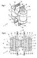
- an interpinous vertebral implant 1according to a first embodiment of the invention comprises an upper support 2, a lower support 3 and two elastic members 4 interposed between the supports 2, 3.
- Each support 2, 3comprises a plate 5 , 6 elongated in the lateral direction and in the central portion of which is provided a U-shaped recess 7 extending in the anteroposterior direction.
- the side walls of the recess 7are extended by a pair of fins 8 which protrudes from the outer surface of the plate 5, 6.
- the pair of fins 8form with the recess 7 an attachment member to an apophysis thorny.
- the recess 7 and the space between the fins 8are intended to receive a spinous process, the maintenance of the latter in the member 7, 8 being ensured for example by one or more synthetic ligaments as will be explained more far in relation to the figure 5 .
- the respective fasteners 7, 8 of the supports 2, 3are located in the same sagittal plane P, which constitutes a plane of symmetry for the implant 1.
- Each support 2, 3, with its plate 5, 6 and its fins 8is typically a one-piece piece made of a biocompatible material, for example metallic, of greater hardness than this of the elastic members 4.
- the elastic members 4are aligned in the lateral direction and are located on either side of the sagittal plane of symmetry P.
- the elastic members 4are elastically compressible in the direction of the spine (vertical direction P on the figure 2 ) and are typically made of a viscoelastic material such as silicone.
- the elastic members 4have a generally cylindrical annular shape and their ends rest, without being fixed by any other means, in annular recesses 9 made in the inner faces facing the plates 5, 6.
- Each elastic member 4surrounds a rigid guide rod 10, typically metallic, which extends parallel to the plane P, in the direction of the spine, and which is connected at both ends to the plates 5, 6 of the supports 2, 3, respectively.
- Each guide rod 10is more precisely in the form of a screw whose threaded end 11 is screwed into a corresponding threaded bore 12 of the plate 5 of the upper support 2 and whose head 13 bears against an annular shoulder 14 defined by a through bore 15 of the plate 6 of the lower support 3.
- the head 13 of the screws 10 and the shoulders 14constitute stops which reliably limit the spacing of the supports 2, 3 and thus prevent them from separating during the flexion movements of the patient
- the elastic members 4are thus kept permanently in place around the guide rods 4.
- the guide rods 10are screwed so as to sufficiently bring the supports 2, 3 so that the elastic members 4 are in a prestressed state before the introduction of the implant.
- Such prestressingallows the implant to support loads up to a certain threshold without additional compression of the elastic members 4. It is in particular possible to choose the prestress condition so that once the implant is in place it is able to support the loads exerted by the spine, when the patient is in the erected station, without additional compression of the elastic members 4. This ensures effective maintenance of the separation of the spinous processes.
- the implant 1further comprises, preferably, two studs 16 which protrude from one another on the respective inner faces of the plates 5, 6, in the central part of the implant 1, between the organs 4. These pads 16 may abut against each other during extension movements of the patient to limit the compression of the elastic members 4 and thus protect them.
- the space between the elastic members 4can be used to bring the fastener 7, 8 of the upper support 2 of the fastener 7, 8 of the lower support 3.
- a disadvantage of interspinous implants traditionalis that they require resecting part of the spinous processes to clear enough space for the insertion of the implant. Such resection, in addition to its tedious nature, can lead to fragility and then rupture of the spinous processes.
- the implant according to the inventionsuch a resection is not necessary, or can be performed in a minimal way, thanks to the recesses 7 for receiving the spinous processes which are practiced in the plates 5, 6 and which are close to the one of the other.
- the distance d between the respective bottoms of the recesses 7is substantially equal to or even less than the height h of the elastic members 4.
- the implantcan be put in place without resection of the spinous processes while having elastic members 4 of high height and large damping capacity.
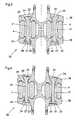
- FIG. 3 and 4show an interspinous vertebral implant 20 according to a second embodiment of the invention.
- This implant 20differs from the implant 1 according to the first embodiment in that the guide rods 21 are not screwed into one of the plates but have at each of their ends a hemispherical head 22, 23. These hemispherical heads 22, 23 rest in housings of hemispherical shape 24 but larger radius formed in the plates 25 of the supports 26.
- the two heads 22, 23 of each guide rod 21act as stops to limit the spacing of 26. At least one of these heads 22, 23 is a nut 23 which cooperates with a thread 27 of the rod 21 to adjust the spacing of the supports 26 and thus the prestressing of the elastic members 4.
- the spherical shape of the heads 22, 23 and housings 24allows the supports 26 to tilt relative to each other in the frontal plane during lateral bending movement of the patient, as shown in FIG. figure 4 .
- the figure 5shows how implant 1 or 20 according to the invention can be put in place.
- the implantis placed between two consecutive spinous processes 30, 31 if necessary by compressing the elastic members 4 to facilitate the insertion of the implant and then releasing the compression force once the implant in place.
- the fins 8each comprise a slot 32 (cf. figure 1 ) extending in the anteroposterior direction. These slots 32 allow the passage of one or more synthetic ligaments serving to maintain flexibly the spinous processes 30, 31 in the fasteners 7, 8.
- these synthetic ligamentsare more or less stressed during bending movements of the patient.
- these synthetic ligamentsallow a spacing of the vertebrae even when the spacing of the supports 2, 3, respectively 26, is blocked by the stops 13, 14, respectively 22, 23, 24. This spacing of the vertebrae remains however in physiological limits.
- a piece 35is used to stop and unite the end portions of a ligament without making a knot.
- This pieceis represented in figures 6 and 7 . It comprises an annular portion 36 having pins 37 on its upper and lower surfaces and two parallel tongues 38 attached at one of their ends to the outer peripheral surface of the annular portion 36 and brought back over the annular portion 36 by a folding of 180 °.
- the figure 8shows the stop piece 35 before folding the tabs 38.
- the stop piece 35is placed free next to the implant with its lower face facing the implant.
- a synthetic ligament 39passes around the implant substantially in the frontal plane through the slits 32 of the fins 8 and bypassing the upper spinous process 30 by its upper end and the inferior spinous process 31 by its lower end.
- the two ends of the ligament 39pass into the central part of the opening 40 of the annular portion 36 by the underside of the latter, then form a loop around the tongues 38 respectively to retrace the opening 40 in the peripheral portion thereof.
- the ends of the ligament 39are left free. By pulling on these ends, the surgeon squeezes the ligament 39 in the stop piece 35.
- the pins 37then cooperate with the ligament 39 to ensure proper maintenance of the latter.
Landscapes
- Health & Medical Sciences (AREA)
- Orthopedic Medicine & Surgery (AREA)
- Life Sciences & Earth Sciences (AREA)
- Neurology (AREA)
- Surgery (AREA)
- Heart & Thoracic Surgery (AREA)
- Engineering & Computer Science (AREA)
- Biomedical Technology (AREA)
- Nuclear Medicine, Radiotherapy & Molecular Imaging (AREA)
- Medical Informatics (AREA)
- Molecular Biology (AREA)
- Animal Behavior & Ethology (AREA)
- General Health & Medical Sciences (AREA)
- Public Health (AREA)
- Veterinary Medicine (AREA)
- Prostheses (AREA)
Abstract
Description
Translated fromFrenchLa présente invention concerne un implant vertébral inter-épineux, c'est-à-dire un implant destiné à être inséré entre les apophyses épineuses de deux vertèbres adjacentes pour servir de stabilisateur et soulager notamment le disque intervertébral.The present invention relates to an interpinous vertebral implant, that is to say an implant intended to be inserted between the spinous processes of two adjacent vertebrae to serve as a stabilizer and particularly to relieve the intervertebral disc.
On connaît par la demande de brevet
Cet implant selon le document
La demande de brevet
- des premier et second supports définissant dans leur partie centrale des organes respectifs de fixation à des apophyses épineuses de deux vertèbres respectives, ces organes de fixation étant situés dans un même plan sagittal, et
- des premier et second organes élastiquement compressibles dans la direction du rachis, ces organes élastiquement compressibles étant disposés entre les premier et second supports et de part et d'autre dudit plan sagittal.
- first and second supports defining in their central part respective fixation members to spinous processes of two respective vertebrae, these fixation members being located in the same sagittal plane, and
- first and second elastically compressible members in the direction of the spine, these elastically compressible members being disposed between the first and second supports and on either side of said sagittal plane.
Les organes élastiquement compressibles sont sous la forme de soufflets définissant des enceintes étanches remplies d'un fluide et d'un noyau en un matériau viscoélastique. Cet implant selon le document
La présente invention vise à remédier aux inconvénients précités de l'état de la technique et propose à cet effet un implant vertébral inter-épineux comprenant les caractéristiques mentionnées plus haut en rapport avec le document
Ainsi, les organes rigides assurent à la fois une fonction de guidage et une fonction de butée. Cet agencement permet de garantir que les organes élastiques resteront bien en place dans l'implant et de conférer une grande robustesse aux butées. L'implant selon l'invention peut présenter un faible encombrement dans la direction antéro-postérieure, ce qui permet notamment de conserver une bonne partie des ligaments naturels. L'encombrement de l'implant dans la direction latérale est peu gênant car les tissus correspondants sont surtout constitués par du muscle.Thus, the rigid members provide both a guiding function and a stop function. This arrangement ensures that the resilient members will remain in place in the implant and give great strength to the stops. The implant according to the invention may have a small footprint in the anteroposterior direction, which allows in particular to retain a good portion of the natural ligaments. The size of the implant in the lateral direction is not a problem because the corresponding tissues consist mainly of muscle.
Des modes de réalisation particuliers de l'invention sont définis dans les revendications dépendantes annexées 2 à 12.Particular embodiments of the invention are defined in the dependent
D'autres caractéristiques et avantages de la présente invention apparaîtront à la lecture de la description détaillée suivante de plusieurs modes de réalisation de l'invention faite en référence aux dessins annexés dans lesquels :
- les
figures 1 et 2 sont respectivement une vue en perspective et une vue en coupe frontale d'un implant vertébral inter-épineux selon un premier mode de réalisation ; - les
figures 3 et 4 sont des vues en coupe frontale d'un implant vertébral inter-épineux selon un second mode de réalisation, respectivement dans une position droite et dans une position inclinée ; - la
figure 5 est une vue plane frontale montrant un implant selon l'invention en place entre deux apophyses épineuses ; - les
figures 6 et7 sont respectivement une vue en perspective et une vue de profil d'une pièce d'arrêt utilisée pour arrêter un ligament servant au maintien de l'implant selon l'invention entre deux apophyses épineuses ; et - la
figure 8 est une vue en perspective de la pièce d'arrêt dans un état intermédiaire non plié.
- the
Figures 1 and 2 are respectively a perspective view and a front sectional view of an interspinous vertebral implant according to a first embodiment; - the
Figures 3 and 4 are frontal sectional views of an interspinous vertebral implant according to a second embodiment, respectively in a straight position and in an inclined position; - the
figure 5 is a frontal plane view showing an implant according to the invention in place between two spinous processes; - the
figures 6 and7 are respectively a perspective view and a side view of a stopper used to stop a ligament for maintaining the implant according to the invention between two spinous processes; and - the
figure 8 is a perspective view of the stop piece in an unfolded intermediate state.
En référence aux
Les organes élastiques 4 sont alignés dans la direction latérale et sont situés de part et d'autre du plan sagittal de symétrie P. Les organes élastiques 4 sont élastiquement compressibles dans la direction du rachis (direction verticale P sur la
De préférence, les tiges de guidage 10 sont vissées de manière à rapprocher suffisamment les supports 2, 3 pour que les organes élastiques 4 soient dans un état de précontrainte avant la mise en place de l'implant. Une telle précontrainte permet à l'implant de supporter des charges jusqu'à un certain seuil sans compression supplémentaire des organes élastiques 4. Il est notamment possible de choisir l'état de précontrainte de telle sorte qu'une fois l'implant mis en place, il soit capable de supporter les charges exercées par le rachis, lorsque le patient est dans la station érigée, sans compression supplémentaire des organes élastiques 4. Ceci permet de garantir un maintien efficace de l'écartement des apophyses épineuses.Preferably, the
L'implant 1 comprend en outre, de préférence, deux plots 16 qui font saillie en regard l'un de l'autre sur les faces intérieures respectives des platines 5, 6, dans la partie centrale de l'implant 1, entre les organes élastiques 4. Ces plots 16 peuvent venir en butée l'un contre l'autre pendant des mouvements d'extension du patient pour limiter la compression des organes élastiques 4 et protéger ainsi ces derniers.The
Comme on peut le voir à la
Les
La
Traditionnellement, de tels ligaments synthétiques sont arrêtés et unis les uns aux autres au moyen de noeuds. Selon une caractéristique de l'invention, une pièce 35 est utilisée pour arrêter et unir les parties d'extrémité d'un ligament sans faire de noeud. Cette pièce est représentée aux
Comme représenté à la
Claims (12)
Translated fromFrenchPriority Applications (9)
| Application Number | Priority Date | Filing Date | Title |
|---|---|---|---|
| EP07010112AEP1994900A1 (en) | 2007-05-22 | 2007-05-22 | Interspinous vertebral implant |
| US12/124,801US8021395B2 (en) | 2007-05-22 | 2008-05-21 | Interspinous vertebral implant |
| BRPI0811846-9A2ABRPI0811846A2 (en) | 2007-05-22 | 2008-05-21 | INTERSPINHAL VERTEBRAL IMPLANT AND DEVICE |
| EP08762708.9AEP2164412B1 (en) | 2007-05-22 | 2008-05-21 | Inter-spine vertebral implant |
| ES08762708.9TES2524010T3 (en) | 2007-05-22 | 2008-05-21 | Interspinous vertebral implant |
| PCT/IB2008/001266WO2008142537A1 (en) | 2007-05-22 | 2008-05-21 | Inter-spine vertebral implant |
| CN2008800167500ACN101686842B (en) | 2007-05-22 | 2008-05-21 | Intervertebral Implants |
| MX2009012147AMX2009012147A (en) | 2007-05-22 | 2008-05-21 | Inter-spine vertebral implant. |
| US13/231,203US20120004727A1 (en) | 2007-05-22 | 2011-09-13 | Method Of Implanting An Interspinous Vertebral Implant |
Applications Claiming Priority (1)
| Application Number | Priority Date | Filing Date | Title |
|---|---|---|---|
| EP07010112AEP1994900A1 (en) | 2007-05-22 | 2007-05-22 | Interspinous vertebral implant |
Publications (1)
| Publication Number | Publication Date |
|---|---|
| EP1994900A1true EP1994900A1 (en) | 2008-11-26 |
Family
ID=38564525
Family Applications (2)
| Application Number | Title | Priority Date | Filing Date |
|---|---|---|---|
| EP07010112AWithdrawnEP1994900A1 (en) | 2007-05-22 | 2007-05-22 | Interspinous vertebral implant |
| EP08762708.9AActiveEP2164412B1 (en) | 2007-05-22 | 2008-05-21 | Inter-spine vertebral implant |
Family Applications After (1)
| Application Number | Title | Priority Date | Filing Date |
|---|---|---|---|
| EP08762708.9AActiveEP2164412B1 (en) | 2007-05-22 | 2008-05-21 | Inter-spine vertebral implant |
Country Status (7)
| Country | Link |
|---|---|
| US (2) | US8021395B2 (en) |
| EP (2) | EP1994900A1 (en) |
| CN (1) | CN101686842B (en) |
| BR (1) | BRPI0811846A2 (en) |
| ES (1) | ES2524010T3 (en) |
| MX (1) | MX2009012147A (en) |
| WO (1) | WO2008142537A1 (en) |
Cited By (1)
| Publication number | Priority date | Publication date | Assignee | Title |
|---|---|---|---|---|
| US8696709B2 (en) | 2011-06-30 | 2014-04-15 | Ldr Medical | Interspinous implant and implantation instrument |
Families Citing this family (45)
| Publication number | Priority date | Publication date | Assignee | Title |
|---|---|---|---|---|
| US8241330B2 (en) | 2007-01-11 | 2012-08-14 | Lanx, Inc. | Spinous process implants and associated methods |
| US9055981B2 (en) | 2004-10-25 | 2015-06-16 | Lanx, Inc. | Spinal implants and methods |
| US9028550B2 (en) | 2005-09-26 | 2015-05-12 | Coalign Innovations, Inc. | Selectively expanding spine cage with enhanced bone graft infusion |
| US9867640B2 (en) | 2006-12-07 | 2018-01-16 | Nexus Spine, LLC | Press-on pedicle screw assembly |
| US9265532B2 (en) | 2007-01-11 | 2016-02-23 | Lanx, Inc. | Interspinous implants and methods |
| US9247968B2 (en) | 2007-01-11 | 2016-02-02 | Lanx, Inc. | Spinous process implants and associated methods |
| US8308801B2 (en)* | 2007-02-12 | 2012-11-13 | Brigham Young University | Spinal implant |
| US9314346B2 (en)* | 2007-02-12 | 2016-04-19 | Brigham Young University | Spinal implant |
| US20110172708A1 (en)* | 2007-06-22 | 2011-07-14 | Simpirica Spine, Inc. | Methods and systems for increasing the bending stiffness of a spinal segment with elongation limit |
| US8894687B2 (en) | 2011-04-25 | 2014-11-25 | Nexus Spine, L.L.C. | Coupling system for surgical construct |
| US12232975B2 (en) | 2008-02-22 | 2025-02-25 | Howmedica Osteonics Corp. | Lockable spinal implant |
| US8932355B2 (en) | 2008-02-22 | 2015-01-13 | Coalign Innovations, Inc. | Spinal implant with expandable fixation |
| US8992620B2 (en) | 2008-12-10 | 2015-03-31 | Coalign Innovations, Inc. | Adjustable distraction cage with linked locking mechanisms |
| US20100145455A1 (en) | 2008-12-10 | 2010-06-10 | Innvotec Surgical, Inc. | Lockable spinal implant |
| US20100004748A1 (en)* | 2008-07-03 | 2010-01-07 | Cordaro Nicholas M | Intervertebral prosthesis |
| WO2010016949A1 (en)* | 2008-08-08 | 2010-02-11 | Alphatec Spine, Inc. | Spinous process device and method of use |
| US9044278B2 (en)* | 2008-11-06 | 2015-06-02 | Spinal Kinetics Inc. | Inter spinous process spacer with compressible core providing dynamic stabilization |
| CA2743721A1 (en)* | 2009-02-19 | 2010-08-26 | Anton E. Bowden | Compliant dynamic spinal implant |
| WO2010096829A2 (en) | 2009-02-23 | 2010-08-26 | Crocker Spinal, L.L.C. | Press-on link for surgical screws |
| US9157497B1 (en) | 2009-10-30 | 2015-10-13 | Brigham Young University | Lamina emergent torsional joint and related methods |
| BR112012020550A2 (en)* | 2010-03-04 | 2017-06-27 | Synthes Gmbh | expandable laminar implant for spinal fusion. |
| FR2964850B1 (en)* | 2010-09-17 | 2013-08-09 | Spineart Sa | SPINNING PINCH SYSTEM AND ITS APPLICATIONS |
| EP3097878A1 (en)* | 2011-02-06 | 2016-11-30 | Paradigm Spine, LLC | Translaminar interspinous stabilization system |
| US8496689B2 (en) | 2011-02-23 | 2013-07-30 | Farzad Massoudi | Spinal implant device with fusion cage and fixation plates and method of implanting |
| US8425560B2 (en) | 2011-03-09 | 2013-04-23 | Farzad Massoudi | Spinal implant device with fixation plates and lag screws and method of implanting |
| WO2012177412A2 (en) | 2011-06-07 | 2012-12-27 | Brigham Young University | Serpentine spinal stability device and associated methods |
| US20120323276A1 (en)* | 2011-06-17 | 2012-12-20 | Bryan Okamoto | Expandable interspinous device |
| US11812923B2 (en) | 2011-10-07 | 2023-11-14 | Alan Villavicencio | Spinal fixation device |
| AU2013308332B2 (en) | 2012-08-31 | 2017-01-19 | Newsouth Innovations Pty Limited | Bone stabilization device and methods of use |
| WO2015028853A1 (en) | 2013-08-30 | 2015-03-05 | Newsouth Innovations Pty Limited | Spine stabilization device |
| US9259249B2 (en)* | 2013-11-26 | 2016-02-16 | Globus Medical, Inc. | Spinous process fixation system and methods thereof |
| WO2015081240A1 (en) | 2013-11-27 | 2015-06-04 | Coalign Innovations, Inc. | Structurally supporting insert for spinal fusion cage |
| US9642651B2 (en) | 2014-06-12 | 2017-05-09 | Brigham Young University | Inverted serpentine spinal stability device and associated methods |
| HK1259385A1 (en) | 2015-07-31 | 2019-11-29 | Paradigm Spine, Llc. | Interspinous stabilization and fusion device |
| US10548738B2 (en) | 2016-04-07 | 2020-02-04 | Howmedica Osteonics Corp. | Expandable interbody implant |
| AU2017203369B2 (en) | 2016-05-20 | 2022-04-28 | Vb Spine Us Opco Llc | Expandable interbody implant with lordosis correction |
| AU2017228529B2 (en) | 2016-09-12 | 2022-03-10 | Vb Spine Us Opco Llc | Interbody implant with independent control of expansion at multiple locations |
| AU2017251734B2 (en) | 2016-10-26 | 2022-10-20 | Vb Spine Us Opco Llc | Expandable interbody implant with lateral articulation |
| EP3456294B1 (en) | 2017-09-15 | 2024-06-05 | Stryker European Operations Holdings LLC | Intervertebral body fusion device expanded with hardening material |
| CN110537969B (en)* | 2019-09-10 | 2024-03-19 | 陕西东望科技有限公司 | Auxiliary nail placing device for thoracolumbar vertebra nail placing operation |
| US12011360B2 (en) | 2021-10-22 | 2024-06-18 | Linares Spinal Devices, Llc | Expandable spinal jack for installation between upper and lower succeeding superior articular processes |
| US12137947B2 (en) | 2021-11-02 | 2024-11-12 | Linares Spinal Devices, Llc | Expandable spinal jack for installation between upper and lower succeeding superior articular processes |
| US11432937B1 (en) | 2021-11-02 | 2022-09-06 | Linares Medical Devices, Llc | Expandable spinal jack for installation between upper and lower succeeding superior articular processes |
| CN116370161B (en)* | 2022-12-31 | 2025-07-22 | 浙江德康医疗器械有限公司 | A non-fusion lumbar motion system |
| CN116747051B (en)* | 2023-08-22 | 2023-11-24 | 北京大学第三医院(北京大学第三临床医学院) | Bone implant |
Citations (6)
| Publication number | Priority date | Publication date | Assignee | Title |
|---|---|---|---|---|
| FR2709245A1 (en)* | 1993-08-27 | 1995-03-03 | Fairant Paulette | Internal dynamic vertebral orthesis |
| FR2774581A1 (en)* | 1998-02-10 | 1999-08-13 | Dimso Sa | INTEREPINOUS STABILIZER TO BE ATTACHED TO SPINOUS APOPHYSIS OF TWO VERTEBRES |
| US20020143331A1 (en)* | 1998-10-20 | 2002-10-03 | Zucherman James F. | Inter-spinous process implant and method with deformable spacer |
| WO2003045262A2 (en)* | 2001-11-30 | 2003-06-05 | Spine Next | Intervertebral implant with elastically deformable wedge |
| US20050049708A1 (en)* | 2000-04-04 | 2005-03-03 | Atkinson Robert E. | Devices and methods for the treatment of spinal disorders |
| US20060036240A1 (en)* | 2004-08-09 | 2006-02-16 | Innovative Spinal Technologies | System and method for dynamic skeletal stabilization |
Family Cites Families (12)
| Publication number | Priority date | Publication date | Assignee | Title |
|---|---|---|---|---|
| FR2709248B1 (en)* | 1993-08-27 | 1995-09-29 | Martin Jean Raymond | Ancillary equipment for placing a spinal instrumentation. |
| FR2709247B1 (en)* | 1993-08-27 | 1995-09-29 | Martin Jean Raymond | Device for anchoring spinal instrumentation on a vertebra. |
| FR2722393B1 (en)* | 1993-08-27 | 1996-08-23 | Martin Jean Raymond | ANCILLARY MATERIAL FOR CORRECTING A VERTEBRAL DEFORMATION |
| US6056059A (en)* | 1996-03-11 | 2000-05-02 | Schlumberger Technology Corporation | Apparatus and method for establishing branch wells from a parent well |
| FR2775183B1 (en)* | 1998-02-20 | 2000-08-04 | Jean Taylor | INTER-SPINOUS PROSTHESIS |
| FR2799640B1 (en)* | 1999-10-15 | 2002-01-25 | Spine Next Sa | IMPLANT INTERVETEBRAL |
| US20060015181A1 (en)* | 2004-07-19 | 2006-01-19 | Biomet Merck France (50% Interest) | Interspinous vertebral implant |
| JP2006059880A (en)* | 2004-08-17 | 2006-03-02 | Fujitsu Ltd | Semiconductor device and manufacturing method thereof |
| US7837688B2 (en)* | 2005-06-13 | 2010-11-23 | Globus Medical | Spinous process spacer |
| EP1942817B1 (en)* | 2005-09-27 | 2014-05-07 | Paradigm Spine, LLC | Interspinous vertebral stabilization devices |
| US8062298B2 (en)* | 2005-10-15 | 2011-11-22 | Baxano, Inc. | Flexible tissue removal devices and methods |
| US7922745B2 (en)* | 2006-01-09 | 2011-04-12 | Zimmer Spine, Inc. | Posterior dynamic stabilization of the spine |
- 2007
- 2007-05-22EPEP07010112Apatent/EP1994900A1/ennot_activeWithdrawn
- 2008
- 2008-05-21BRBRPI0811846-9A2Apatent/BRPI0811846A2/ennot_activeApplication Discontinuation
- 2008-05-21MXMX2009012147Apatent/MX2009012147A/enactiveIP Right Grant
- 2008-05-21USUS12/124,801patent/US8021395B2/enactiveActive
- 2008-05-21WOPCT/IB2008/001266patent/WO2008142537A1/enactiveApplication Filing
- 2008-05-21CNCN2008800167500Apatent/CN101686842B/ennot_activeExpired - Fee Related
- 2008-05-21EPEP08762708.9Apatent/EP2164412B1/enactiveActive
- 2008-05-21ESES08762708.9Tpatent/ES2524010T3/enactiveActive
- 2011
- 2011-09-13USUS13/231,203patent/US20120004727A1/ennot_activeAbandoned
Patent Citations (6)
| Publication number | Priority date | Publication date | Assignee | Title |
|---|---|---|---|---|
| FR2709245A1 (en)* | 1993-08-27 | 1995-03-03 | Fairant Paulette | Internal dynamic vertebral orthesis |
| FR2774581A1 (en)* | 1998-02-10 | 1999-08-13 | Dimso Sa | INTEREPINOUS STABILIZER TO BE ATTACHED TO SPINOUS APOPHYSIS OF TWO VERTEBRES |
| US20020143331A1 (en)* | 1998-10-20 | 2002-10-03 | Zucherman James F. | Inter-spinous process implant and method with deformable spacer |
| US20050049708A1 (en)* | 2000-04-04 | 2005-03-03 | Atkinson Robert E. | Devices and methods for the treatment of spinal disorders |
| WO2003045262A2 (en)* | 2001-11-30 | 2003-06-05 | Spine Next | Intervertebral implant with elastically deformable wedge |
| US20060036240A1 (en)* | 2004-08-09 | 2006-02-16 | Innovative Spinal Technologies | System and method for dynamic skeletal stabilization |
Cited By (4)
| Publication number | Priority date | Publication date | Assignee | Title |
|---|---|---|---|---|
| US8696709B2 (en) | 2011-06-30 | 2014-04-15 | Ldr Medical | Interspinous implant and implantation instrument |
| US9402658B2 (en) | 2011-06-30 | 2016-08-02 | Ldr Medical | Interspinous implant and instrument for implanting an interspinous implant |
| US10478234B2 (en) | 2011-06-30 | 2019-11-19 | Ldr Medical | Interspinous implant and implantation instrument |
| US10517652B2 (en) | 2011-06-30 | 2019-12-31 | Ldr Medical | Interspinous implant and instrument for implanting an interspinous implant |
Also Published As
| Publication number | Publication date |
|---|---|
| BRPI0811846A2 (en) | 2014-11-18 |
| CN101686842A (en) | 2010-03-31 |
| US20120004727A1 (en) | 2012-01-05 |
| WO2008142537A1 (en) | 2008-11-27 |
| EP2164412B1 (en) | 2014-09-03 |
| ES2524010T3 (en) | 2014-12-03 |
| US20090005819A1 (en) | 2009-01-01 |
| US8021395B2 (en) | 2011-09-20 |
| CN101686842B (en) | 2012-10-03 |
| EP2164412A1 (en) | 2010-03-24 |
| MX2009012147A (en) | 2010-02-17 |
Similar Documents
| Publication | Publication Date | Title |
|---|---|---|
| EP2164412B1 (en) | Inter-spine vertebral implant | |
| EP1330987B1 (en) | Interspinous vertebral implant | |
| EP1448109B1 (en) | Intervertebral implant with elastically deformable wedge | |
| EP1372541B1 (en) | Stabilised interbody fusion system for vertebrae | |
| EP1926444B2 (en) | Vertebral fixing systemw | |
| EP1558158B1 (en) | Dynamic device for intervertebral linkage with multidirectional controlled displacement | |
| EP0645986B1 (en) | Spinal therapy apparatus | |
| FR2835174A1 (en) | CONNECTOR FOR SPINAL OSTEOSYNTHESIS DEVICE, BONE ANCHOR CONNECTOR / DEVICE ASSEMBLY AND SPINAL OSTEOSYNTHESIS DEVICE USING THE SAME | |
| EP1997449A2 (en) | Device and assembly for rear dynamic guidance of the spine and spine treatment system comprising such a device | |
| EP3416576B1 (en) | Dynamically stabilizing vertebral implant, and surgical kit comprising same | |
| FR2838041A1 (en) | SPINAL OSTEOSYNTHESIS SYSTEM | |
| WO1997025931A1 (en) | Anchoring device for posterior vertebral osteosynthesis | |
| FR2703239A1 (en) | Pin for interspinal prosthesis | |
| FR2831420A1 (en) | APPARATUS FOR HOLDING THE SPIN WITH A PINCH ASSEMBLY | |
| EP1744690A1 (en) | Intervertebral implant | |
| WO2011124789A1 (en) | Transverse connection system and device for the vertebral column | |
| FR2863860A1 (en) | Bone anchor screw for correcting deformations of vertebral column, has longitudinal rods arranged inside head, in sequenced manner in two columns, and cap placed on head in unclamped state, before introduction of rods in head | |
| EP2182869A2 (en) | Extra-discal intervertebral stabilization element for arthrodesis | |
| WO2005094704A1 (en) | Intervertebral connecting device with controlled multi-directional movements | |
| WO2005110257A1 (en) | Modular flexible and adjustable vertebral connector element for an intervertebral device | |
| FR2905847A1 (en) | ELEMENT OF A DEVICE FOR STABILIZING THE RACHIS, AND DEVICE COMPRISING A PAIR OF SUCH ELEMENTS. | |
| FR2777449A1 (en) | Ligament tensioning instrument for use in a spine stabilizing system | |
| FR2783698A1 (en) | SPINAL OSTEOSYNTHESIS DEVICE WITH MEDIAN ANCHOR HOOK ON THE POSTERIOR VERTEBRAL ARCH | |
| FR3018442A1 (en) | IMPROVED ANCHOR SCREW FOR VERTEBRATES STABILIZATION AND OSTEOSYNTHESIS SYSTEM COMPRISING SUCH SCREWS | |
| WO2016062963A1 (en) | Polyaxial vertebral anchoring device for straightening a vertebra |
Legal Events
| Date | Code | Title | Description |
|---|---|---|---|
| PUAI | Public reference made under article 153(3) epc to a published international application that has entered the european phase | Free format text:ORIGINAL CODE: 0009012 | |
| AK | Designated contracting states | Kind code of ref document:A1 Designated state(s):AT BE BG CH CY CZ DE DK EE ES FI FR GB GR HU IE IS IT LI LT LU LV MC MT NL PL PT RO SE SI SK TR | |
| AX | Request for extension of the european patent | Extension state:AL BA HR MK RS | |
| AKX | Designation fees paid | ||
| REG | Reference to a national code | Ref country code:DE Ref legal event code:8566 | |
| STAA | Information on the status of an ep patent application or granted ep patent | Free format text:STATUS: THE APPLICATION IS DEEMED TO BE WITHDRAWN | |
| 18D | Application deemed to be withdrawn | Effective date:20090527 |