EP1994673B1 - Role aware network security enforcement - Google Patents
Role aware network security enforcementDownload PDFInfo
- Publication number
- EP1994673B1 EP1994673B1EP07758046.2AEP07758046AEP1994673B1EP 1994673 B1EP1994673 B1EP 1994673B1EP 07758046 AEP07758046 AEP 07758046AEP 1994673 B1EP1994673 B1EP 1994673B1
- Authority
- EP
- European Patent Office
- Prior art keywords
- binding
- address
- user
- bindings
- source address
- Prior art date
- Legal status (The legal status is an assumption and is not a legal conclusion. Google has not performed a legal analysis and makes no representation as to the accuracy of the status listed.)
- Active
Links
- 230000027455bindingEffects0.000claimsdescription162
- 238000009739bindingMethods0.000claimsdescription162
- 238000000034methodMethods0.000claimsdescription47
- 230000004044responseEffects0.000claimsdescription8
- 230000008569processEffects0.000claimsdescription5
- 238000004891communicationMethods0.000description18
- 238000001914filtrationMethods0.000description12
- 238000010586diagramMethods0.000description10
- 230000000644propagated effectEffects0.000description9
- 230000006870functionEffects0.000description7
- 238000012545processingMethods0.000description7
- 238000013459approachMethods0.000description6
- 230000008859changeEffects0.000description6
- 230000007246mechanismEffects0.000description6
- 230000003287optical effectEffects0.000description5
- 230000005540biological transmissionEffects0.000description3
- 230000008901benefitEffects0.000description2
- 230000008878couplingEffects0.000description2
- 238000010168coupling processMethods0.000description2
- 238000005859coupling reactionMethods0.000description2
- 230000003068static effectEffects0.000description2
- 230000005641tunnelingEffects0.000description2
- RYGMFSIKBFXOCR-UHFFFAOYSA-NCopperChemical compound[Cu]RYGMFSIKBFXOCR-UHFFFAOYSA-N0.000description1
- 238000013475authorizationMethods0.000description1
- 230000000903blocking effectEffects0.000description1
- 230000001413cellular effectEffects0.000description1
- 230000001010compromised effectEffects0.000description1
- 238000011156evaluationMethods0.000description1
- 239000000835fiberSubstances0.000description1
- 238000002347injectionMethods0.000description1
- 239000007924injectionSubstances0.000description1
- 238000007726management methodMethods0.000description1
- 238000012986modificationMethods0.000description1
- 230000004048modificationEffects0.000description1
- 229920001690polydopaminePolymers0.000description1
- 238000012546transferMethods0.000description1
- 238000013519translationMethods0.000description1
- 238000010200validation analysisMethods0.000description1
Images


Classifications
- H—ELECTRICITY
- H04—ELECTRIC COMMUNICATION TECHNIQUE
- H04L—TRANSMISSION OF DIGITAL INFORMATION, e.g. TELEGRAPHIC COMMUNICATION
- H04L63/00—Network architectures or network communication protocols for network security
- H04L63/02—Network architectures or network communication protocols for network security for separating internal from external traffic, e.g. firewalls
- H04L63/0227—Filtering policies
- H04L63/0263—Rule management
- H—ELECTRICITY
- H04—ELECTRIC COMMUNICATION TECHNIQUE
- H04L—TRANSMISSION OF DIGITAL INFORMATION, e.g. TELEGRAPHIC COMMUNICATION
- H04L61/00—Network arrangements, protocols or services for addressing or naming
- H04L61/50—Address allocation
- H04L61/5076—Update or notification mechanisms, e.g. DynDNS
- H—ELECTRICITY
- H04—ELECTRIC COMMUNICATION TECHNIQUE
- H04L—TRANSMISSION OF DIGITAL INFORMATION, e.g. TELEGRAPHIC COMMUNICATION
- H04L63/00—Network architectures or network communication protocols for network security
- H04L63/10—Network architectures or network communication protocols for network security for controlling access to devices or network resources
- H04L63/101—Access control lists [ACL]
- H—ELECTRICITY
- H04—ELECTRIC COMMUNICATION TECHNIQUE
- H04L—TRANSMISSION OF DIGITAL INFORMATION, e.g. TELEGRAPHIC COMMUNICATION
- H04L63/00—Network architectures or network communication protocols for network security
- H04L63/10—Network architectures or network communication protocols for network security for controlling access to devices or network resources
- H04L63/102—Entity profiles
- H—ELECTRICITY
- H04—ELECTRIC COMMUNICATION TECHNIQUE
- H04L—TRANSMISSION OF DIGITAL INFORMATION, e.g. TELEGRAPHIC COMMUNICATION
- H04L63/00—Network architectures or network communication protocols for network security
- H04L63/20—Network architectures or network communication protocols for network security for managing network security; network security policies in general
- H—ELECTRICITY
- H04—ELECTRIC COMMUNICATION TECHNIQUE
- H04W—WIRELESS COMMUNICATION NETWORKS
- H04W12/00—Security arrangements; Authentication; Protecting privacy or anonymity
- H04W12/08—Access security
- H04W12/088—Access security using filters or firewalls
- H—ELECTRICITY
- H04—ELECTRIC COMMUNICATION TECHNIQUE
- H04L—TRANSMISSION OF DIGITAL INFORMATION, e.g. TELEGRAPHIC COMMUNICATION
- H04L63/00—Network architectures or network communication protocols for network security
- H04L63/02—Network architectures or network communication protocols for network security for separating internal from external traffic, e.g. firewalls
- H04L63/0227—Filtering policies
- H04L63/0236—Filtering by address, protocol, port number or service, e.g. IP-address or URL
Definitions
- the present inventiongenerally relates to network security.
- the inventionrelates more specifically to a method and apparatus for role based security using source addresses.
- Access control listsare one way to control network traffic. Access control lists filter network traffic by controlling whether routed packets are forwarded or blocked, typically at a router interface, although other devices can filter packets. The router examines each packet to determine whether to forward or drop the packet, on the basis of the criteria specified within the access lists. An access control list criterion could be the source address of the traffic or the destination address of the traffic.
- IP addressesonce served as invariable identifiers of the source device on an IP-based network. Access control lists were developed to allow differentiated access based on this IP identifier within the network. However, IP addresses are no longer tightly bound to either a device or a user. For example, at one point in time, entities were statically addressed. Moreover, laptops, PDAs, and other mobile devices did not exist. Today, with dynamic DHCP addressing and mobile devices seeking network access, the significance that can be placed on a given IP address over another for the purpose of identifying a user of device has declined significantly. As a result, ACLs in all but the broadest implementations have been far less useful.
- IP addressesFor example, one technique defines a subnet per-role and associates a VLAN per role on the access switch. When the user authenticates, the user's or device's role is determined, which results in a specific VLAN (and subsequent subnet) assignment.
- US 2003/115344discloses a method of access control management includes determining a private network address for a user in connection with the user accessing a network resource, determining an access control list entry for the user based on an access control policy, translating a public network address to the private network address for the user accessing the network resource, and allowing or blocking the user access based on the access control list entry, wherein determining the access control list entry is performed before translating the public network address to the private network address.
- US 2004/083382discloses a method that includes providing a policy on a policy server, the policy having a service definition that contains first and second relational components, providing first and second network entities, operatively coupling the first and second network entities to the policy server, dynamically associating the first network entity with the second network entity (wherein such associating includes binding the first relational component of the service definition in the policy to the first network entity, and binding the second relational component of the service definition in the policy to the second network entity), and enforcing the policy on the first and second network entities.
- US 2004/073671discloses a dedicated data packet filtering processor whose only function is to filter data packets based on a list of source IP addresses stored in highspeed memory of the processor.
- the processorhas a specialized operating system which controls the operation of the processor.
- the processorexamines the source IP address of each received data packet to determine if the source IP address matches one of the stored source IP addresses, and if there is a match, either discards or forwards the data packet depending on the processor configuration.
- the list of source IP addressesare updated by a service provider having a central administrative site. The service provider keeps these lists up to data and periodically updates the source IP addresses stored in the random access memory of the dedicated IP filtering processors.
- the present inventioncomprises, in one aspect, a method of distributing a security policy in a network in which source addresses are dynamically bound to devices.
- the methodcomprises generating a binding between a source address and the role or roles of a user accessing the network via a device coupled to an ingress path comprising one or more nodes.
- a devicecoupled to an ingress path comprising one or more nodes.
- the source addressis currently assigned to the device.
- the bindingmay be generated by one or more nodes on the ingress path.
- the ingress pathmay be a path used during authentication of the user or device itself.
- the bindingis distributed to a filter node that is not on the ingress path. Responsive to a determination that the user is associated with a new source address, a new binding is generated to associate a new source address with the role or roles for the user. The new binding is distributed to the filter node.
- timeout valuesare associated with the bindings.
- a filter nodereceives bindings that associate source addresses to respective roles.
- the source addressescomprise a source address assigned to a device that accesses the network via an ingress path, wherein the filter node is not on the ingress path.
- the filter nodestores the bindings to use for filtering packets.
- the filter nodeuses one of the bindings to filter the packet.
- the filteringis based on a role in the binding for the source address in the packet. For example, the filter node determines if it has a binding for the source address in the packet.
- the filter nodeResponsive to a determination that the filter node has the binding, the filter node processes the packet in accordance with the role or roles bound to the source address. In one aspect, responsive to a determination that the filter node does not have the binding, the filter node transmits a request for the binding. The filter node may either drop the packet or quarantine the packet while it waits for the requested binding.
- the inventionencompasses a computer apparatus and a computer-readable medium configured to carry out the foregoing steps.
- FIG. 1Ais a block diagram that illustrates an example network arrangement 100 in which an embodiment can be used.
- the arrangement 100has the ability to control user access to portions of the arrangement 100 based on the user's role.
- the user 102amay or may not be permitted to access one of the resources 103 a-d based on the user's role.
- the user 102amay be assigned one or more roles by a system administrator, and the roles may be stored on the authentication server 120, or is at least accessible by the authentication server 120.
- a policy server(not depicted in FIG. 1A ) may store the roles.
- a device other than the authentication server 120can provide the user roles.
- a user 102a currently associated with client 104ais communicatively coupled to an access device 106a.
- Client 104is any network-compatible end station, such as a personal digital assistant (PDA), cellular telephone, personal computer, or workstation.
- PDApersonal digital assistant
- the user 102ais free to use different client devices (e.g., 104a, 104b, 104c) or, in the case of a mobile client device, move the client device 104a to a different location.
- client devicese.g., 104a, 104b, 104c
- an egress nodemay function as an access device.
- egress node 140functions as an ingress device when processing packets from client 104c.
- Access device 106is, in one embodiment, a network router that is configured to perform access control functions.
- the access device 106may be a switch, network element that supports VPN, wireless gateway, firewall, etc.
- the access device 106is also referred to herein as an ingress device.
- An access devicecan function as an egress node, depending on the direction of flow of network traffic.
- binding logic 142 in an access device 106aWhen a user 102a at the client node 104a first accesses the network 108, binding logic 142 in an access device 106a generates a binding between the client's source address and roles for the user 102a.
- the source addressis an IP address in accordance with one embodiment. However, the source address is not limited to being an IP address.
- the binding informationis learned through an authentication exchange, in accordance with an embodiment. However, alternative methods could be used. In an embodiment using 802.1x authentication with network communication, the 802.1x authenticator (e.g., access device 106) will learn from the authentication server 120 whether the user should be permitted or denied access and if so, what the user's roles are.
- Authentication server 120is a computer that is configured to securely store user authentication information such as usemames and passwords, and to perform authentication protocols, algorithms, and supporting processes, such as one-time password (OTP) validation, encryption and decryption, message digest evaluation, etc.
- authentication server 120communicates with access device 106a using a secure protocol that is optimized for use in authentication. Examples of suitable protocols are RADIUS and TACACS.
- a policy serveris communicatively coupled to network 108 and/or to authentication server 120, or is integrated with the authentication server 120.
- the policy serverprovides a repository of user roles.
- client 104may initially authenticate itself to access device 106a, in cooperation with authentication server 120.
- the ATUL (Address to User Lookup) query server 145is capable of performing a response protocol for finding out network parameters about a user. For example, in response to a request that specifies an IP address, the ATUL query server 145 returns the identity of the user currently assigned the IP address.
- one or more devices on the ingress pathdetermine a binding of source address to user roles. "Binding,” in this context, means a stored association of data items.
- the ingress pathmay include all devices that are involved in establishing the user's source address and role. For example, the access device 106a, authentication server 120, and DHCP server 130 are all on the ingress path for client 104a. Depending on how user roles are learned and source addresses are assigned, other devices could be on the ingress path.
- the binding of source address to user rolesis propagated to a filter node that is not on the ingress path.
- the bindingsare propagated to one or more of the egress nodes 140a, 140b.
- the egress nodesare used herein as an example of a filter node; however, it is not required that the filter nodes be egress nodes.
- the binding informationis propagated from the point at which the binding information is learned (e.g., the access device 106, authentication server 120, etc.) to a device that might use the binding information for filtering decisions.
- bindingsare propagated without any request from the filter device for the bindings.
- a bindingis transferred to a device that requests the binding for a specific source address.
- the egress nodes 140store the bindings of source addresses to roles for use in filtering packets at the egress node 140.
- filtering logic 152 of the egress nodesearches its address-role binding table 150 to determine if the egress node 140 has a binding for the source address in the packet. If the egress node 140 does not have a binding, it may send a query requesting the binding. Further, the egress node 140 may take additional steps such as dropping or quarantining the packet. If the egress node 140 does have the binding, it processes the packet according with the roles bound to the source address.
- one or more of the devicesstore address-role bindings.
- an access device 106may store address-role bindings 130 for client devices 104 that it serves.
- a DHCP server 130may have an address to role table 144 of the bindings for IP addresses that it assigned.
- the address-role binding table 150 on the egress nodes 140may hold bindings for source addresses in packets processed at the egress node 140.
- the egress node 140may obtain these bindings by request.
- the egress nodeholds bindings for all (or substantially all) users. These bindings may be delivered to the egress node without the egress node requesting them.
- FIG. 1Bdepicts an address-role binding table 150, in accordance with an embodiment of the present invention.
- the table 150includes columns for the source addresses, associated roles, and timeout values. Each row of the table 150 contains a binding 150a of source address to role.
- the table 150has an optional user ID, which identifies the user 102.
- a timeout valuemay represent a time to live, which can be used to expire the binding.
- the access device 106only uses the bindings to filter packets when the access device 106 needs to control access to a resource 103. For example, if the destination address in the packet from the user 102a is on the same subnet as access device 106a (e.g., resource 103 a), access device 106a uses the bindings to filter the packet. In many cases, an access device 106 forwards packets without doing any filtering, and a downstream device filters the packets based on the bindings. An access device 106 may function as an egress node 140, and vice versa. For example, egress node 140a may act as an access device for client 104c.
- a particular usermay become associated with a new source address.
- user 102acould become associated with a new IP address if user 102a logs off client device 104a and the IP address assigned to client device 104a is reassigned to a different client device.
- the user 102acould be associated with a new IP address.
- the user 102amight also become associated with a new IP address by logging into a different client device. Therefore, the binding of a particular source address to role can become stale.
- each bindinghas a timeout value associated with it.
- the DHCP server 130provides a lease time for the source address.
- the binding timeout valueis set to be equal or less to this value. Considerations with respect to DHCP releases are discussed herein below.
- Propagation of bindingsdoes not require a substantial amount of data transfer or storage. For example, even if roles, UserIDs and source addresses are propagated, only 20 bytes of information is propagated (assuming 8 bytes for role and UserIds and 12 bytes for source addresses). Even on massive networks with 100,000 users, this is only 2MB of data. If only source addresses and roles are propagated this can be further reduced to 1.2MB.
- the egress nodes 140provide role-based access control within an enterprise.
- Role-based ACLsare configured at egress points substituting the source and possibly the destination (based on policy) addresses of an ACL with roles or userIDs. These role-based ACLs are then updated based on the source addresses associated with the entities represented in the ACL. Exemplary locations for such filtering in the enterprise include, but are not limited to:
- FIG. 2Ais a flow diagram that illustrates a high level overview of one embodiment of a method for distributing source address to role bindings for enforcing a security protocol.
- FIG. 2A-2Breference communications among elements of FIG. 1A .
- FIG. 1Arepresents merely one example of a network arrangement, and the techniques described herein may be used in many other network arrangements.
- a binding of a source address to a role of a useris generated.
- the bindingis generated by one or more devices on an ingress path through which the user connects.
- the ingress pathmay include access device 106, authentication server 120, DHCP server 130, etc.
- the bindingmay include, but is not limited to, a source address (e.g., IP address), a role or roles, and a timeout value.
- the bindingis distributed to a filter node (or nodes) 140.
- the filter nodeis not on the ingress path, in one embodiment
- the bindingis distributed in response to a request for a blinding for a specified source address, in one embodiment.
- the bindingis distributed to all or predominantly all nodes that might use it for filtering, in another embodiment.
- the bindingmay be distributed without receiving a request for it in the latter case.
- the source addressesare not bound persistently to a given user or device. Therefore, it is possible that a user will be associated with a different source address (or vice versa) when that user either logs onto a different client machine, or that machine obtains a new source address.
- a new bindingis generated to associate the new source address with a role for the user 102. The previous binding will become invalid upon expiration of the binding timeout.
- the new bindingis distributed to the filter node(s) 140. Similar to block 204, the new binding may distributed to the filter node either responsive to a specific I request from then filter node, or the new binding may be distributed to filter nodes without a request.
- FIG. 2Bis a flow diagram that illustrates a high level overview of one embodiment of a method for enforcing source address to role bindings at a filter node.
- the filter nodereceives and stores bindings.
- the bindingsassociate source addresses to respective roles.
- the source addressesinclude a source address assigned to a device that accesses the network via an ingress path. Further, the filter node is not on the ingress path.
- the filter nodemay be at an egress point; however, the filter node is not limited to being at an egress point.
- the filter nodereceives a packet.
- the filter nodedetermines if it has a binding for the source address in the packet.
- the packetis filtered, in block 258, in accordance with the role associated with the source address. For example, policies associated with the role or roles associated with the source address are used to determine the policy for processing the packet.
- the filter node 140causes the packet to not be forwarded, in block 260.
- the packetmay be dropped by the filter node.
- the packetmaybe quarantined such that it may be forwarded later, if the filter node receives a valid role binding for the source address.
- the filter nodemay request a binding for the source address, in block 262.
- the filter nodewill with high probability receive the bindings by the time the packet is retransmitted by the source and arrives at the filter node.
- Block 262is optional in that the filter node may simply drop or quarantine the packet without requesting a binding for the source address.
- the bindingsare delivered to filter nodes (e.g., egress nodes 140) prior to a specific request for them from a filter node. This is referred to as “pre-population delivery.”
- the bindingsare delivered to nodes responsive to a request for a binding for a specific source address. This is referred to as “on demand delivery.”
- the address-to-role bindingsare propagated to substantially all nodes that may need to implement a security policy.
- the address-to-role bindingsmay be distributed through a reliable multicast mechanism.
- the address-to-role bindingsmay be distributed through a unicast mechanism.
- the authentication server 120propagates the bindings. However, another device may be used to propagate the bindings. In one aspect, the authentication server 120 performs a mass revocation of the bindings. For example, the authentication server 120 may revoke the bindings if a policy change affects the roles. The authentication server 120 can revoke the bindings even though their associated binding timers have not yet expired.
- the address-to-role bindingsare, in general, only propagated when requested. For example, when an egress node determines that it does not have the binding for a source address in a packet it is processing, it transmits a request for this binding. In one aspect, the egress node transmits a packet addressed to the source address with an "alert" flag set (e.g., a router alert flag which causes all routers on the path to that node to intercept and examine the packet before forwarding it). As the packet passes through the network to the device currently assigned the source address, eventually it will be received by the on-path device that has the bindings for source address.
- an "alert" flag sete.g., a router alert flag which causes all routers on the path to that node to intercept and examine the packet before forwarding it.
- the access deviceconsumes the packet rather than forwarding it, responsive to a determination that the packet is a request for the binding of a source for which it has the binding. Then, the access device returns the binding to the device that sent the packet in a response packet. For example, egress node 140b transmits a packet with a source address currently assigned to client 104a. Eventually, access device 106a strips the packet off the network 106 and sends an appropriate binding to the egress node 140b.
- the egress nodewhen it does not have a binding for a source address, it sends a query to a device that is able to provide network parameters about a user. For example, the egress node sends a request specifying an IP address to the ATUL query server 145.
- ATULAddress to User Lookup
- ATUL query server 145In response to the request, the ATUL query server 145 returns the identity of the user currently assigned the IP address. More generally, any technique for determining a user's identity from an IP address may be used.
- the address-to-role bindingsare stored on nodes that serve as repositories.
- a filter nodeneeds the bindings, it sends a request to one of the repositories, which either returns the bindings or forwards the request to another repository.
- the repositoriesare DHCP servers.
- a deviceneeds bindings, it sends a request to its local DHCP server. For example, assume that egress node 140b needs a binding that is stored at DHCP server 130a. The egress node 140b may send a request to DHCP server 130b, which determines whether it has the requested binding. Because in this example it does not, it determines another DHCP server in a hierarchy to send the request to. Eventually, the request is received by DHCP server 130a, which returns the requested binding to the egress node 140b.
- the on demand approachincludes reduced storage requirements at the filter node, as entities only hold as much data as they need based on the packets processed at the filtering point.
- the systemis highly scalable, as additional filter nodes can be added to handle additional users without requiring that current filter nodes store additional bindings.
- the egress and ingress pointswill find each other through the normal operation of the protocol. For example, there is no need for the ingress device to know which egress nodes may need to filter based on the source address, as the ingress node waits until it receives a query from the egress node to propagate the binding. Moreover. The egress node does not need to know where the bindings are stored, as the query it sends can be based on the source address it knows from the packet it is processing. Alternatively, the query can be sent to a repository, which either provides the bindings or forwards the request to another repository.
- a combination of the pre-population, on demand and repository device approachesmay be used. For example, when a device needs a binding it may query a DHCP server when possible or send a request with a router alert flag set in a packet addressed to the source address.
- the decision on which model to usemay be based on the size of the network. For smaller networks the pre-population may be preferred. For larger networks, the on-demand model may be preferred to save resources on each device. Another factor in this choice is the degree of change on the network.
- a client devicedoes not release its DHCP lease.
- some deviceswill explicitly issue a command to the DHCP server to release the lease prior to the end of the lease.
- the client's IP addresscould be reassigned by the DHCP server. This could cause a policy conflict if the egress node(s) were not made aware of the change of role for the IP address.
- the access devicedrops all DHCP release requests to prevent reassignment of the IP address by the DHCP server.
- the access device 106quarantines the DHCP release until the binding timer expires.
- the releaseis forwarded to the DHCP server, along with an indication of how long it needs to wait before reassigning the source address.
- a devicecould be used by more than one user to access the network. In such a case, it is possible that after a first user logs off, a second user can be authorized to access the network without a new IP address being assigned to the device. Typically, a new IP address is not provided even though there is a new authorization. In one aspect, when a login is attempted without seeking a new IP address, the login is not allowed until the binding timer expires. In one aspect, the network access device forces a DHCP release to force an IP address reassignment.
- a technique to mitigate consequences of multi-user devicesis to keep the timeout value associated with the binding relatively short. This will cause the filter nodes to request a new binding with sufficient frequency to mitigate the problem of a second user sending packets with the source address bound to another user.
- Another techniqueis to have the ingress device spoof the source MAC address of the client device to force the DHCP server to give the client device a new IP address.
- Still another techniqueis for the ingress device to NAT (Network Address Translation) the client device that has the new user.
- NATNetwork Address Translation
- the source address of the packetis altered at the ingress device such that when the egress node looks at the IP address it determines that is does not have a binding for the source address. Therefore, the egress node queries for a new binding.
- the NAT entry at the access devicecan be flushed once the binding timer expires.
- Yet another techniqueis to inform the DHCP server that a new user has an IP address that is bound to another user's role.
- the DHCP serverwould respond to this information by forcing the client device to obtain a new IP address.
- a filter nodemaintains one-way hash values based on the bindings in table 150 and periodically queries a database for a hash of the current bindings. If a comparison of the hash with a computation of the hash of bindings stored on the filter node reveals that there are changes to the binding, then the filter node requests an access device to provide an update of the bindings. The filter node could also request that the current version of the bindings be sent without first determining if there are changes.
- An exemplary techniqueis RPF (reverse path forwarding), which is a technique that looks at the ingress interface value and determines if the packet came in from a port that it would be expected to go out to. Unicast RPF checks should also be done throughout the network in an effort to prevent the injection of spoofed packets elsewhere.
- Other exemplary techniquesare IP source guard and DHCP snooping, which are used to learn the IP address the client receives and bind it to just that port to prevent spoofing.
- the filter nodesrate limit the queries issued for bindings, in accordance with one embodiment.
- filter nodesonly generate a certain number of requests for bindings in a particular time period.
- a denial of service attackmight occur by a malicious host sending packets with source addresses for which bindings have not been generated, or at least are not stored on a filter node processing the packets. Were the filter node to send queries for all of the source addresses, the network traffic could become unacceptably high and possibly lead to denial of service.
- FIG. 3is a block diagram that illustrates a general-purpose computer system 300 upon which an embodiment of the invention may be implemented.
- Computer system 300includes a bus 302 or other communication mechanism for communicating information, and a processor 304 coupled with bus 302 for processing information.
- Computer system 300also includes a main memory 306, such as a random access memory (“RAM”) or other dynamic storage device, coupled to bus 302 for storing information and instructions to be executed by processor 304.
- Main memory 306also may be used for storing temporary variables or other intermediate information during execution of instructions to be executed by processor 304.
- Computer system 300further includes a read only memory (“ROM”) 308 or other static storage device coupled to bus 302 for storing static information and instructions for processor 304.
- ROMread only memory
- a storage device 310such as a magnetic disk or optical disk, is provided and coupled to bus 302 for storing information and instructions.
- Computer system 300may be coupled via bus 302 to a display 312, such as a cathode ray tube ("CRT"), for displaying information to a computer user.
- a display 312such as a cathode ray tube ("CRT")
- cursor control 316is Another type of user input device, such as a mouse, trackball, stylus, or cursor direction keys for communicating direction information and command selections to processor 304 and for controlling cursor movement on display 312.
- This input devicetypically has two degrees of freedom in two axes, a first axis (e.g., x) and a second axis (e.g., y), that allows the device to specify positions in a plane.
- the inventionis related to the use of computer system 300 for role-based security using source addresses.
- role-based security using source addressesis provided by computer system 300 in response to processor 304 executing one or more sequences of one or more instructions contained in main memory 306. Such instructions may be read into main memory 306 from another computer-readable medium, such as storage device 310. Execution of the sequences of instructions contained in main memory 306 causes processor 304 to perform the process steps described herein.
- hard-wired circuitrymay be used in place of or in combination with software instructions to implement the invention. Thus, embodiments of the invention are not limited to any specific combination of hardware circuitry and software.
- Non-volatile mediaincludes, for example, optical or magnetic disks, such as storage device 310.
- Volatile mediaincludes dynamic memory, such as main memory 306.
- Transmission mediaincludes coaxial cables, copper wire and fiber optics, including the wires that comprise bus 302. Transmission media can also take the form of acoustic or light waves, such as those generated during radio wave and infrared data communications.
- Computer-readable mediainclude, for example, a floppy disk, a flexible disk, hard disk, magnetic tape, or any other magnetic medium, a CD-ROM, any other optical medium, punchcards, papertape, any other physical medium with patterns of holes, a RAM, a PROM, and EPROM, a FLASH-EPROM, any other memory chip or cartridge, a carrier wave as described hereinafter, or any other medium from which a computer can read.
- Various forms of computer readable mediamay be involved in carrying one or more sequences of one or more instructions to processor 304 for execution.
- the instructionsmay initially be carried on a magnetic disk of a remote computer.
- the remote computercan load the instructions into its dynamic memory and send the instructions over a telephone line using a modem.
- a modem local to computer system 300can receive the data on the telephone line and use an infrared transmitter to convert the data to an infrared signal.
- An infrared detectorcan receive the data carried in the infrared signal and appropriate circuitry can place the data on bus 302.
- Bus 302carries the data to main memory 306, from which processor 304 retrieves and executes the instructions.
- the instructions received by main memory 306may optionally be stored on storage device 310 either before or after execution by processor 304.
- Computer system 300also includes a communication interface 318 coupled to bus 302.
- Communication interface 318provides a two-way data communication coupling to a network link 320 that is connected to a local network 322.
- communication interface 318may be an integrated services digital network ("ISDN") card or a modem to provide a data communication connection to a corresponding type of telephone line.
- ISDNintegrated services digital network
- communication interface 318may be a local area network (“LAN”) card to provide a data communication connection to a compatible LAN.
- LANlocal area network
- Wireless linksmay also be implemented.
- communication interface 318sends and receives electrical, electromagnetic or optical signals that carry digital data streams representing various types of information.
- Network link 320typically provides data communication through one or more networks to other data devices.
- network link 320may provide a connection through local network 322 to a host computer 324 or to data equipment operated by an Internet Service Provider ("ISP") 326.
- ISP 326in turn provides data communication services through the worldwide packet data communication network now commonly referred to as the "Internet” 328.
- Internet 328uses electrical, electromagnetic or optical signals that carry digital data streams.
- the signals through the various networks and the signals on network link 320 and through communication interface 318, which carry the digital data to and from computer system 300,are exemplary forms of carrier waves transporting the information.
- Computer system 300can send messages and receive data, including program code, through the network(s), network link 320 and communication interface 318.
- a server 330might transmit a requested code for an application program through Internet 328, ISP 326, local network 322 and communication interface 318.
- one such downloaded applicationprovides for authenticating computing devices as described herein.
- the received codemay be executed by processor 304 as it is received, and/or stored in storage device 310, or other non-volatile storage for later execution. In this manner, computer system 300 may obtain application code in the form of a carrier wave.
Landscapes
- Engineering & Computer Science (AREA)
- Computer Security & Cryptography (AREA)
- Computer Networks & Wireless Communication (AREA)
- Signal Processing (AREA)
- Computer Hardware Design (AREA)
- Computing Systems (AREA)
- General Engineering & Computer Science (AREA)
- Business, Economics & Management (AREA)
- General Business, Economics & Management (AREA)
- Data Exchanges In Wide-Area Networks (AREA)
- Computer And Data Communications (AREA)
Description
- The present invention generally relates to network security. The invention relates more specifically to a method and apparatus for role based security using source addresses.
- The approaches described in this section could be pursued, but are not necessarily approaches that have been previously conceived or pursued. Therefore, unless otherwise indicated herein, the approaches described in this section are not prior art to the claims in this application and are not admitted to be prior art by inclusion in this section.
- It is often desirable to differentiate access to a network or resource in a network based on attributes of the user or device seeking access. For example, an engineering manager may be allowed access to a server having information related to engineering, as well as a server having personnel information. However, an engineer may not be allowed access to the personnel information. Similarly, a piece of laboratory equipment may be permitted access to other laboratory equipment, but not to servers performing business functions. Thus, it is desirable to control network traffic in order to control access to a resource, device, or network, based on one or more characteristics of a user or device. One technique for role-based access control is described byFerraiolo and Kuhn in, "Role-Based Access Control" (Proceedings of the 15th National Security Computer Conference, 1992).
- Access control lists are one way to control network traffic. Access control lists filter network traffic by controlling whether routed packets are forwarded or blocked, typically at a router interface, although other devices can filter packets. The router examines each packet to determine whether to forward or drop the packet, on the basis of the criteria specified within the access lists. An access control list criterion could be the source address of the traffic or the destination address of the traffic.
- Internet Protocol (IP) addresses once served as invariable identifiers of the source device on an IP-based network. Access control lists were developed to allow differentiated access based on this IP identifier within the network. However, IP addresses are no longer tightly bound to either a device or a user. For example, at one point in time, entities were statically addressed. Moreover, laptops, PDAs, and other mobile devices did not exist. Today, with dynamic DHCP addressing and mobile devices seeking network access, the significance that can be placed on a given IP address over another for the purpose of identifying a user of device has declined significantly. As a result, ACLs in all but the broadest implementations have been far less useful.
- There have been several attempts to address this problem. One technique inserts, into every frame sent on a network, a 16-bit tag defining the role associated with the traffic. However, this technique places a burden on the hardware to insert and interpret the tags. Other techniques use "tunneling," e.g. IPSEC VPN tunneling, to identify the source of traffic as being associated with a given tunnel.
- Other techniques constrain the assignment of IP addresses to follow the roles rather than the network topology. For example, one technique defines a subnet per-role and associates a VLAN per role on the access switch. When the user authenticates, the user's or device's role is determined, which results in a specific VLAN (and subsequent subnet) assignment.
US 2003/115344 discloses a method of access control management includes determining a private network address for a user in connection with the user accessing a network resource, determining an access control list entry for the user based on an access control policy, translating a public network address to the private network address for the user accessing the network resource, and allowing or blocking the user access based on the access control list entry, wherein determining the access control list entry is performed before translating the public network address to the private network address.US 2004/083382 discloses a method that includes providing a policy on a policy server, the policy having a service definition that contains first and second relational components, providing first and second network entities, operatively coupling the first and second network entities to the policy server, dynamically associating the first network entity with the second network entity (wherein such associating includes binding the first relational component of the service definition in the policy to the first network entity, and binding the second relational component of the service definition in the policy to the second network entity), and enforcing the policy on the first and second network entities.US 2004/073671 discloses a dedicated data packet filtering processor whose only function is to filter data packets based on a list of source IP addresses stored in highspeed memory of the processor. The processor has a specialized operating system which controls the operation of the processor. The processor examines the source IP address of each received data packet to determine if the source IP address matches one of the stored source IP addresses, and if there is a match, either discards or forwards the data packet depending on the processor configuration. The list of source IP addresses are updated by a service provider having a central administrative site. The service provider keeps these lists up to data and periodically updates the source IP addresses stored in the random access memory of the dedicated IP filtering processors. Based on the foregoing, there is a clear need for an improved method for differentiating access to a resource or network, based on user or device identity.- The present invention is illustrated by way of example, and not by way of limitation, in the figures of the accompanying drawings and in which like reference numerals refer to similar elements and in which:
FIG. 1A is a block diagram that illustrates an overview of a network in accordance with an embodiment;FIG. 1B is a block diagram that illustrates an overview of a network in accordance with an embodiment;FIG. 2A is a flow diagram that illustrates a high level overview of an embodiment of a method for distributing a role based security policy;FIG. 2B is a flow diagram that illustrates a high level overview of an embodiment of a method of enforcing a role based security policy; andFIG. 3 is a block diagram that illustrates a computer system upon which an embodiment may be implemented.- A method and apparatus for role-based security based on source address is described. In the following description, for the purposes of explanation, numerous specific details are set forth in order to provide a thorough understanding of the present invention. It will be apparent, however, to one skilled in the art that the present invention may be practiced without these specific details. In other instances, well-known structures and devices are shown in block diagram form in order to avoid unnecessarily obscuring the present invention.
- Embodiments are described herein according to the following outline:
- 1.0 General Overview
- 2.0 Role Based Security Based on Source Addresses
- 2.1 Structural Overview
- 2.2 Functional Overview
- 3.0 Distribution Mechanisms
- 3.1 Pre-Population of Bindings
- 3.2 On Demand Distribution of Bindings
- 3.3 Combination Approaches
- 4.0 Other Considerations
- 4.1 DHCP Releases
- 4.2 Multi-User Devices
- 4.3 Role Changes While Binding Still Valid
- 4.4 IP Spoofing
- 4.5 Denial of Service Attacks
- 5.0 Implementation Mechanisms: Hardware Overview
- 6.0 Extensions and Alternatives
- 1.0 GENERAL OVERVIEW
- The needs identified in the foregoing Background, and other needs and objects that will become apparent for the following description, are achieved in the present invention, which comprises, in one aspect, a method of distributing a security policy in a network in which source addresses are dynamically bound to devices. In this aspect, the method comprises generating a binding between a source address and the role or roles of a user accessing the network via a device coupled to an ingress path comprising one or more nodes. One example of the meaning of the term "role", as used throughout this description, is described byFerraiolo and Kuhn in, "Role-Based Access Control" (Proceedings of the 15th National Security Computer Conference, 1992). However, the meaning of the term "role," as used throughout this description, is not limited to the description of roles in Ferraiolo and Kuhn's paper.
- At the time the binding is made, the source address is currently assigned to the device. The binding may be generated by one or more nodes on the ingress path. The ingress path may be a path used during authentication of the user or device itself. The binding is distributed to a filter node that is not on the ingress path. Responsive to a determination that the user is associated with a new source address, a new binding is generated to associate a new source address with the role or roles for the user. The new binding is distributed to the filter node. In one embodiment, timeout values are associated with the bindings.
- Another aspect is a method of enforcing a role-based security policy, using bindings of source addresses to roles. In this aspect, a filter node receives bindings that associate source addresses to respective roles. The source addresses comprise a source address assigned to a device that accesses the network via an ingress path, wherein the filter node is not on the ingress path. The filter node stores the bindings to use for filtering packets. Upon receiving a packet, the filter node uses one of the bindings to filter the packet. Thus, the filtering is based on a role in the binding for the source address in the packet. For example, the filter node determines if it has a binding for the source address in the packet. Responsive to a determination that the filter node has the binding, the filter node processes the packet in accordance with the role or roles bound to the source address. In one aspect, responsive to a determination that the filter node does not have the binding, the filter node transmits a request for the binding. The filter node may either drop the packet or quarantine the packet while it waits for the requested binding.
- In other aspects, the invention encompasses a computer apparatus and a computer-readable medium configured to carry out the foregoing steps.
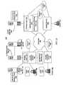
FIG. 1A is a block diagram that illustrates anexample network arrangement 100 in which an embodiment can be used. Thearrangement 100 has the ability to control user access to portions of thearrangement 100 based on the user's role. For example, the user 102a may or may not be permitted to access one of the resources 103 a-d based on the user's role. The user 102a may be assigned one or more roles by a system administrator, and the roles may be stored on theauthentication server 120, or is at least accessible by theauthentication server 120. For example, a policy server (not depicted inFIG. 1A ) may store the roles. Thus, a device other than theauthentication server 120 can provide the user roles.- A user 102a currently associated with
client 104a is communicatively coupled to anaccess device 106a. Client 104 is any network-compatible end station, such as a personal digital assistant (PDA), cellular telephone, personal computer, or workstation. The user 102a is free to use different client devices (e.g., 104a, 104b, 104c) or, in the case of a mobile client device, move theclient device 104a to a different location. Thus a given user 102 may access the network viadifferent access devices - Access device 106 is, in one embodiment, a network router that is configured to perform access control functions. Alternatively, the access device 106 may be a switch, network element that supports VPN, wireless gateway, firewall, etc. The access device 106 is also referred to herein as an ingress device. An access device can function as an egress node, depending on the direction of flow of network traffic.
- When a user 102a at the
client node 104a first accesses thenetwork 108, bindinglogic 142 in anaccess device 106a generates a binding between the client's source address and roles for the user 102a. The source address is an IP address in accordance with one embodiment. However, the source address is not limited to being an IP address. The binding information is learned through an authentication exchange, in accordance with an embodiment. However, alternative methods could be used. In an embodiment using 802.1x authentication with network communication, the 802.1x authenticator (e.g., access device 106) will learn from theauthentication server 120 whether the user should be permitted or denied access and if so, what the user's roles are. Authentication server 120 is a computer that is configured to securely store user authentication information such as usemames and passwords, and to perform authentication protocols, algorithms, and supporting processes, such as one-time password (OTP) validation, encryption and decryption, message digest evaluation, etc. In one embodiment,authentication server 120 communicates withaccess device 106a using a secure protocol that is optimized for use in authentication. Examples of suitable protocols are RADIUS and TACACS.- Optionally a policy server is communicatively coupled to
network 108 and/or toauthentication server 120, or is integrated with theauthentication server 120. The policy server provides a repository of user roles. In this arrangement, client 104 may initially authenticate itself to accessdevice 106a, in cooperation withauthentication server 120. - The ATUL (Address to User Lookup)
query server 145 is capable of performing a response protocol for finding out network parameters about a user. For example, in response to a request that specifies an IP address, theATUL query server 145 returns the identity of the user currently assigned the IP address. - Thus, one or more devices on the ingress path determine a binding of source address to user roles. "Binding," in this context, means a stored association of data items. The ingress path may include all devices that are involved in establishing the user's source address and role. For example, the
access device 106a,authentication server 120, andDHCP server 130 are all on the ingress path forclient 104a. Depending on how user roles are learned and source addresses are assigned, other devices could be on the ingress path. - The binding of source address to user roles is propagated to a filter node that is not on the ingress path. For example, the bindings are propagated to one or more of the
egress nodes authentication server 120, etc.) to a device that might use the binding information for filtering decisions. In one embodiment, bindings are propagated without any request from the filter device for the bindings. In another embodiment, a binding is transferred to a device that requests the binding for a specific source address. - The egress nodes 140 store the bindings of source addresses to roles for use in filtering packets at the egress node 140. When the egress node 140 receives a packet,
filtering logic 152 of the egress node searches its address-role binding table 150 to determine if the egress node 140 has a binding for the source address in the packet. If the egress node 140 does not have a binding, it may send a query requesting the binding. Further, the egress node 140 may take additional steps such as dropping or quarantining the packet. If the egress node 140 does have the binding, it processes the packet according with the roles bound to the source address. - In an embodiment, one or more of the devices store address-role bindings. For example, an access device 106 may store address-
role bindings 130 for client devices 104 that it serves. ADHCP server 130 may have an address to role table 144 of the bindings for IP addresses that it assigned. The address-role binding table 150 on the egress nodes 140 may hold bindings for source addresses in packets processed at the egress node 140. The egress node 140 may obtain these bindings by request. In one embodiment, the egress node holds bindings for all (or substantially all) users. These bindings may be delivered to the egress node without the egress node requesting them. FIG. 1B depicts an address-role binding table 150, in accordance with an embodiment of the present invention. The table 150 includes columns for the source addresses, associated roles, and timeout values. Each row of the table 150 contains a binding 150a of source address to role. The table 150 has an optional user ID, which identifies the user 102. A timeout value may represent a time to live, which can be used to expire the binding.- Typically, the access device 106 only uses the bindings to filter packets when the access device 106 needs to control access to a resource 103. For example, if the destination address in the packet from the user 102a is on the same subnet as
access device 106a (e.g.,resource 103 a),access device 106a uses the bindings to filter the packet. In many cases, an access device 106 forwards packets without doing any filtering, and a downstream device filters the packets based on the bindings. An access device 106 may function as an egress node 140, and vice versa. For example,egress node 140a may act as an access device for client 104c. - A particular user may become associated with a new source address. For example, user 102a could become associated with a new IP address if user 102a logs off
client device 104a and the IP address assigned toclient device 104a is reassigned to a different client device. Thus, when the user 102a logs on again toclient device 104a, the user 102a could be associated with a new IP address. The user 102a might also become associated with a new IP address by logging into a different client device. Therefore, the binding of a particular source address to role can become stale. - To prevent a binding from becoming stale, each binding has a timeout value associated with it. In one embodiment, the
DHCP server 130 provides a lease time for the source address. The binding timeout value is set to be equal or less to this value. Considerations with respect to DHCP releases are discussed herein below. - Propagation of bindings does not require a substantial amount of data transfer or storage. For example, even if roles, UserIDs and source addresses are propagated, only 20 bytes of information is propagated (assuming 8 bytes for role and UserIds and 12 bytes for source addresses). Even on massive networks with 100,000 users, this is only 2MB of data. If only source addresses and roles are propagated this can be further reduced to 1.2MB.
- In one aspect, the egress nodes 140 provide role-based access control within an enterprise. Role-based ACLs are configured at egress points substituting the source and possibly the destination (based on policy) addresses of an ACL with roles or userIDs. These role-based ACLs are then updated based on the source addresses associated with the entities represented in the ACL. Exemplary locations for such filtering in the enterprise include, but are not limited to:
- Campus User to Data Center
- Remote VPN User to Data Center
- Branch User to Data Center
- All users to Internet
FIG. 2A is a flow diagram that illustrates a high level overview of one embodiment of a method for distributing source address to role bindings for enforcing a security protocol. For purposes of illustrating a clear example, the following discussion ofFIG. 2A-2B reference communications among elements ofFIG. 1A . However,FIG. 1A represents merely one example of a network arrangement, and the techniques described herein may be used in many other network arrangements.- In
block 202, a binding of a source address to a role of a user is generated. The binding is generated by one or more devices on an ingress path through which the user connects. For example, the ingress path may include access device 106,authentication server 120,DHCP server 130, etc. The binding may include, but is not limited to, a source address (e.g., IP address), a role or roles, and a timeout value. - In
block 204, the binding is distributed to a filter node (or nodes) 140. The filter node is not on the ingress path, in one embodiment The binding is distributed in response to a request for a blinding for a specified source address, in one embodiment. The binding is distributed to all or predominantly all nodes that might use it for filtering, in another embodiment. The binding may be distributed without receiving a request for it in the latter case. - The source addresses are not bound persistently to a given user or device. Therefore, it is possible that a user will be associated with a different source address (or vice versa) when that user either logs onto a different client machine, or that machine obtains a new source address. In
block 206, responsive to a determination that the user is associated with a new source address, a new binding is generated to associate the new source address with a role for the user 102. The previous binding will become invalid upon expiration of the binding timeout. - In
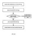
block 208, the new binding is distributed to the filter node(s) 140. Similar to block 204, the new binding may distributed to the filter node either responsive to a specific I request from then filter node, or the new binding may be distributed to filter nodes without a request. FIG. 2B is a flow diagram that illustrates a high level overview of one embodiment of a method for enforcing source address to role bindings at a filter node. Inblock 252, the filter node receives and stores bindings. The bindings associate source addresses to respective roles. The source addresses include a source address assigned to a device that accesses the network via an ingress path. Further, the filter node is not on the ingress path. The filter node may be at an egress point; however, the filter node is not limited to being at an egress point.- In
block 254, the filter node receives a packet. Inblock 256, the filter node determines if it has a binding for the source address in the packet. - If a binding is found, then the packet is filtered, in
block 258, in accordance with the role associated with the source address. For example, policies associated with the role or roles associated with the source address are used to determine the policy for processing the packet. - If a binding is not found, then the filter node 140 causes the packet to not be forwarded, in
block 260. The packet may be dropped by the filter node. Alternatively, the packet maybe quarantined such that it may be forwarded later, if the filter node receives a valid role binding for the source address. - Furthermore, if the binding is not found, the filter node may request a binding for the source address, in
block 262. In the case of packets associated with a reliable transport protocol such as TCP, the filter node will with high probability receive the bindings by the time the packet is retransmitted by the source and arrives at the filter node.Block 262 is optional in that the filter node may simply drop or quarantine the packet without requesting a binding for the source address. - In one aspect, the bindings are delivered to filter nodes (e.g., egress nodes 140) prior to a specific request for them from a filter node. This is referred to as "pre-population delivery." In another aspect, the bindings are delivered to nodes responsive to a request for a binding for a specific source address. This is referred to as "on demand delivery."
- In a pre-population embodiment, the address-to-role bindings are propagated to substantially all nodes that may need to implement a security policy. The address-to-role bindings may be distributed through a reliable multicast mechanism. Alternatively, the address-to-role bindings may be distributed through a unicast mechanism. An advantage of always having the bindings on all nodes that may need it is faster packet processing time. Packets can be processed at the filter nodes immediately, without waiting for the binding information to be transferred to the filter node.
- In one embodiment, the
authentication server 120 propagates the bindings. However, another device may be used to propagate the bindings. In one aspect, theauthentication server 120 performs a mass revocation of the bindings. For example, theauthentication server 120 may revoke the bindings if a policy change affects the roles. Theauthentication server 120 can revoke the bindings even though their associated binding timers have not yet expired. - In an on demand embodiment, the address-to-role bindings are, in general, only propagated when requested. For example, when an egress node determines that it does not have the binding for a source address in a packet it is processing, it transmits a request for this binding. In one aspect, the egress node transmits a packet addressed to the source address with an "alert" flag set (e.g., a router alert flag which causes all routers on the path to that node to intercept and examine the packet before forwarding it). As the packet passes through the network to the device currently assigned the source address, eventually it will be received by the on-path device that has the bindings for source address. The access device consumes the packet rather than forwarding it, responsive to a determination that the packet is a request for the binding of a source for which it has the binding. Then, the access device returns the binding to the device that sent the packet in a response packet. For example,
egress node 140b transmits a packet with a source address currently assigned toclient 104a. Eventually,access device 106a strips the packet off the network 106 and sends an appropriate binding to theegress node 140b. - In another embodiment, when the egress node does not have a binding for a source address, it sends a query to a device that is able to provide network parameters about a user. For example, the egress node sends a request specifying an IP address to the
ATUL query server 145. ATUL (Address to User Lookup) is a request response protocol for finding out network parameters about a user. In response to the request, theATUL query server 145 returns the identity of the user currently assigned the IP address. More generally, any technique for determining a user's identity from an IP address may be used. - In a repository device embodiment, the address-to-role bindings are stored on nodes that serve as repositories. When a filter node needs the bindings, it sends a request to one of the repositories, which either returns the bindings or forwards the request to another repository. In one aspect, the repositories are DHCP servers. When a device needs bindings, it sends a request to its local DHCP server. For example, assume that
egress node 140b needs a binding that is stored atDHCP server 130a. Theegress node 140b may send a request toDHCP server 130b, which determines whether it has the requested binding. Because in this example it does not, it determines another DHCP server in a hierarchy to send the request to. Eventually, the request is received byDHCP server 130a, which returns the requested binding to theegress node 140b. - Advantages of the on demand approach include reduced storage requirements at the filter node, as entities only hold as much data as they need based on the packets processed at the filtering point. Thus, the system is highly scalable, as additional filter nodes can be added to handle additional users without requiring that current filter nodes store additional bindings.
- Further, the egress and ingress points will find each other through the normal operation of the protocol. For example, there is no need for the ingress device to know which egress nodes may need to filter based on the source address, as the ingress node waits until it receives a query from the egress node to propagate the binding. Moreover. The egress node does not need to know where the bindings are stored, as the query it sends can be based on the source address it knows from the packet it is processing. Alternatively, the query can be sent to a repository, which either provides the bindings or forwards the request to another repository.
- A combination of the pre-population, on demand and repository device approaches may be used. For example, when a device needs a binding it may query a DHCP server when possible or send a request with a router alert flag set in a packet addressed to the source address.
- The decision on which model to use may be based on the size of the network. For smaller networks the pre-population may be preferred. For larger networks, the on-demand model may be preferred to save resources on each device. Another factor in this choice is the degree of change on the network.
- Typically a client device does not release its DHCP lease. However, some devices will explicitly issue a command to the DHCP server to release the lease prior to the end of the lease. Thus, the client's IP address could be reassigned by the DHCP server. This could cause a policy conflict if the egress node(s) were not made aware of the change of role for the IP address.
- In one aspect, the access device drops all DHCP release requests to prevent reassignment of the IP address by the DHCP server. In another aspect, the access device 106 quarantines the DHCP release until the binding timer expires. In still another aspect, the release is forwarded to the DHCP server, along with an indication of how long it needs to wait before reassigning the source address.
- In some cases, a device could be used by more than one user to access the network. In such a case, it is possible that after a first user logs off, a second user can be authorized to access the network without a new IP address being assigned to the device. Typically, a new IP address is not provided even though there is a new authorization. In one aspect, when a login is attempted without seeking a new IP address, the login is not allowed until the binding timer expires. In one aspect, the network access device forces a DHCP release to force an IP address reassignment.
- A technique to mitigate consequences of multi-user devices is to keep the timeout value associated with the binding relatively short. This will cause the filter nodes to request a new binding with sufficient frequency to mitigate the problem of a second user sending packets with the source address bound to another user.
- Another technique is to have the ingress device spoof the source MAC address of the client device to force the DHCP server to give the client device a new IP address.
- Still another technique is for the ingress device to NAT (Network Address Translation) the client device that has the new user. In other words, the source address of the packet is altered at the ingress device such that when the egress node looks at the IP address it determines that is does not have a binding for the source address. Therefore, the egress node queries for a new binding. The NAT entry at the access device can be flushed once the binding timer expires.
- Yet another technique is to inform the DHCP server that a new user has an IP address that is bound to another user's role. The DHCP server would respond to this information by forcing the client device to obtain a new IP address.
- It is possible for the role associated with a binding to change without the IP address assigned to the user changing. One technique to mitigate this is to keep the timeout value associated with the binding relatively short. This will cause the filter nodes to request a new binding with sufficient frequency to mitigate change of roles while IP address assignment remains unchanged.
- In another aspect, a filter node maintains one-way hash values based on the bindings in table 150 and periodically queries a database for a hash of the current bindings. If a comparison of the hash with a computation of the hash of bindings stored on the filter node reveals that there are changes to the binding, then the filter node requests an access device to provide an update of the bindings. The filter node could also request that the current version of the bindings be sent without first determining if there are changes.
- Were a device to spoof the IP address of the user, it is possible that the filtering would be compromised. Therefore, techniques to prevent or at least reduce IP spoofing should be used. An exemplary technique is RPF (reverse path forwarding), which is a technique that looks at the ingress interface value and determines if the packet came in from a port that it would be expected to go out to. Unicast RPF checks should also be done throughout the network in an effort to prevent the injection of spoofed packets elsewhere. Other exemplary techniques are IP source guard and DHCP snooping, which are used to learn the IP address the client receives and bind it to just that port to prevent spoofing.
- In order to prevent denial of service attacks, the filter nodes rate limit the queries issued for bindings, in accordance with one embodiment. Thus, filter nodes only generate a certain number of requests for bindings in a particular time period. A denial of service attack might occur by a malicious host sending packets with source addresses for which bindings have not been generated, or at least are not stored on a filter node processing the packets. Were the filter node to send queries for all of the source addresses, the network traffic could become unacceptably high and possibly lead to denial of service.
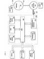
FIG. 3 is a block diagram that illustrates a general-purpose computer system 300 upon which an embodiment of the invention may be implemented.Computer system 300 includes abus 302 or other communication mechanism for communicating information, and aprocessor 304 coupled withbus 302 for processing information.Computer system 300 also includes amain memory 306, such as a random access memory ("RAM") or other dynamic storage device, coupled tobus 302 for storing information and instructions to be executed byprocessor 304.Main memory 306 also may be used for storing temporary variables or other intermediate information during execution of instructions to be executed byprocessor 304.Computer system 300 further includes a read only memory ("ROM") 308 or other static storage device coupled tobus 302 for storing static information and instructions forprocessor 304. Astorage device 310, such as a magnetic disk or optical disk, is provided and coupled tobus 302 for storing information and instructions.Computer system 300 may be coupled viabus 302 to adisplay 312, such as a cathode ray tube ("CRT"), for displaying information to a computer user. Aninput device 314, including alphanumeric and other keys, is coupled tobus 302 for communicating information and command selections toprocessor 304. Another type of user input device iscursor control 316, such as a mouse, trackball, stylus, or cursor direction keys for communicating direction information and command selections toprocessor 304 and for controlling cursor movement ondisplay 312. This input device typically has two degrees of freedom in two axes, a first axis (e.g., x) and a second axis (e.g., y), that allows the device to specify positions in a plane.- The invention is related to the use of
computer system 300 for role-based security using source addresses. According to one embodiment of the invention, role-based security using source addresses is provided bycomputer system 300 in response toprocessor 304 executing one or more sequences of one or more instructions contained inmain memory 306. Such instructions may be read intomain memory 306 from another computer-readable medium, such asstorage device 310. Execution of the sequences of instructions contained inmain memory 306 causesprocessor 304 to perform the process steps described herein. In alternative embodiments, hard-wired circuitry may be used in place of or in combination with software instructions to implement the invention. Thus, embodiments of the invention are not limited to any specific combination of hardware circuitry and software. - The term "computer-readable medium" as used herein refers to any medium that participates in providing instructions to
processor 304 for execution. Such a medium may take many forms, including but not limited to, non-volatile media, volatile media, and transmission media. Non-volatile media includes, for example, optical or magnetic disks, such asstorage device 310. Volatile media includes dynamic memory, such asmain memory 306. Transmission media includes coaxial cables, copper wire and fiber optics, including the wires that comprisebus 302. Transmission media can also take the form of acoustic or light waves, such as those generated during radio wave and infrared data communications. - Common forms of computer-readable media include, for example, a floppy disk, a flexible disk, hard disk, magnetic tape, or any other magnetic medium, a CD-ROM, any other optical medium, punchcards, papertape, any other physical medium with patterns of holes, a RAM, a PROM, and EPROM, a FLASH-EPROM, any other memory chip or cartridge, a carrier wave as described hereinafter, or any other medium from which a computer can read.
- Various forms of computer readable media may be involved in carrying one or more sequences of one or more instructions to
processor 304 for execution. For example, the instructions may initially be carried on a magnetic disk of a remote computer. The remote computer can load the instructions into its dynamic memory and send the instructions over a telephone line using a modem. A modem local tocomputer system 300 can receive the data on the telephone line and use an infrared transmitter to convert the data to an infrared signal. An infrared detector can receive the data carried in the infrared signal and appropriate circuitry can place the data onbus 302.Bus 302 carries the data tomain memory 306, from whichprocessor 304 retrieves and executes the instructions. The instructions received bymain memory 306 may optionally be stored onstorage device 310 either before or after execution byprocessor 304. Computer system 300 also includes acommunication interface 318 coupled tobus 302.Communication interface 318 provides a two-way data communication coupling to anetwork link 320 that is connected to alocal network 322. For example,communication interface 318 may be an integrated services digital network ("ISDN") card or a modem to provide a data communication connection to a corresponding type of telephone line. As another example,communication interface 318 may be a local area network ("LAN") card to provide a data communication connection to a compatible LAN. Wireless links may also be implemented. In any such implementation,communication interface 318 sends and receives electrical, electromagnetic or optical signals that carry digital data streams representing various types of information.- Network link 320 typically provides data communication through one or more networks to other data devices. For example,
network link 320 may provide a connection throughlocal network 322 to ahost computer 324 or to data equipment operated by an Internet Service Provider ("ISP") 326.ISP 326 in turn provides data communication services through the worldwide packet data communication network now commonly referred to as the "Internet" 328.Local network 322 andInternet 328 both use electrical, electromagnetic or optical signals that carry digital data streams. The signals through the various networks and the signals onnetwork link 320 and throughcommunication interface 318, which carry the digital data to and fromcomputer system 300, are exemplary forms of carrier waves transporting the information. Computer system 300 can send messages and receive data, including program code, through the network(s),network link 320 andcommunication interface 318. In the Internet example, aserver 330 might transmit a requested code for an application program throughInternet 328,ISP 326,local network 322 andcommunication interface 318. In accordance with the invention, one such downloaded application provides for authenticating computing devices as described herein.- The received code may be executed by
processor 304 as it is received, and/or stored instorage device 310, or other non-volatile storage for later execution. In this manner,computer system 300 may obtain application code in the form of a carrier wave. - In the foregoing specification, the invention has been described with reference to specific embodiments thereof. It will, however, be evident that various modifications and changes may be made thereto without departing from the scope of the invention. The specification and drawings are, accordingly, to be regarded in an illustrative rather than a restrictive sense.
Claims (13)
- A method for authenticating a computing device, the method comprising:generating (202) a first binding between a first source address and one or more roles of a user accessing the network via a device coupled to the network, wherein the first source address is currently assigned to the device for a lease time of a dynamic host configuration protocol, DHCP, lease, wherein the first binding comprises a timeout value that is based on the lease time;distributing (204) the first binding associated with the first source address to a filter node;before the first binding expires, receiving a request to release the DHCP lease;preventing the DHCP release from resulting in a first DHCP reassignment of the first source address before the first binding expires;determining that the same user is associated with a new source address;responsive to the determining that the same user is associated with the new source address, generating (206) a new binding to associate the new source address with the same one or more roles for the same user; anddistributing (208) the new binding to the filter node;wherein the first source address is a first Internet Protocol, IP, address and the new source address is a new IP address.
- The method of claim 1, further comprising receiving a request from the filter node for the first binding, and wherein the distributing the first binding to the filter node is responsive to the request.
- The method of claim 1, further comprising assigning respective timeout values to the first and the new bindings.
- The method of claim 1, further comprising performing an authentication process that accesses the one or more roles of the user, wherein the one or more roles of the user is learned as a result of the authentication process.
- The method of claim 1, further comprising:generating a plurality of bindings for a corresponding plurality of users; anddistributing the plurality of bindings to a plurality of filter nodes.
- The method of claim 5, wherein the plurality of bindings are distributed to the filter nodes without receiving a request from the filter node for bindings for specified source addresses.
- The method of claim 1, further comprising:responsive to receiving a packet with an alert flag from the filter node, determining that the filter node is requesting a binding for an address that is identified in the packet; andresponsive to determining that the filter node is requesting the binding for the address identified in the packet, transmitting the binding for the address identified in the packet to the filter node.
- The method of claim 1, further comprising:storing the first and new bindings at a server that is able to answer queries for network information for a user associated with a source address.
- The method of claim 1, further comprising:in response to receiving a query from said filter node as to whether said first binding is still valid, transmitting a reply to said filter node that said first binding is no longer valid.
- An apparatus comprising:a network interface that is configured to be coupled to a network for receiving one or more packet flows therefrom;a processor; anda memory having stored thereon one or more sequences of instructions which, when executed by the processor, cause the processor to carry out the steps of any preceding claim.
- The apparatus of claim 10, wherein the apparatus is configured to be coupled to the network via an ingress path comprising one or more nodes, and wherein the filter node is on the ingress path.
- The apparatus of claim 10, wherein the apparatus is configured to be coupled to the network via an ingress path comprising one or more nodes, and wherein the filter node is not on the ingress path.
- A computer readable medium having stored thereon one or more sequences of instructions which, when executed by a processor, cause the processor to carry out the steps of any one of claims 1 to 9.
Applications Claiming Priority (2)
| Application Number | Priority Date | Filing Date | Title |
|---|---|---|---|
| US11/373,727US7814311B2 (en) | 2006-03-10 | 2006-03-10 | Role aware network security enforcement |
| PCT/US2007/063458WO2007106687A2 (en) | 2006-03-10 | 2007-03-07 | Role aware network security enforcement |
Publications (3)
| Publication Number | Publication Date |
|---|---|
| EP1994673A2 EP1994673A2 (en) | 2008-11-26 |
| EP1994673A4 EP1994673A4 (en) | 2011-12-28 |
| EP1994673B1true EP1994673B1 (en) | 2014-11-12 |
Family
ID=38480298
Family Applications (1)
| Application Number | Title | Priority Date | Filing Date |
|---|---|---|---|
| EP07758046.2AActiveEP1994673B1 (en) | 2006-03-10 | 2007-03-07 | Role aware network security enforcement |
Country Status (3)
| Country | Link |
|---|---|
| US (2) | US7814311B2 (en) |
| EP (1) | EP1994673B1 (en) |
| WO (1) | WO2007106687A2 (en) |
Cited By (1)
| Publication number | Priority date | Publication date | Assignee | Title |
|---|---|---|---|---|
| WO2024025946A1 (en)* | 2022-07-28 | 2024-02-01 | Cisco Technology, Inc. | Identity-based policy enforcement in wide area networks |
Families Citing this family (35)
| Publication number | Priority date | Publication date | Assignee | Title |
|---|---|---|---|---|
| US8769604B2 (en)* | 2006-05-15 | 2014-07-01 | Oracle International Corporation | System and method for enforcing role membership removal requirements |
| US8418241B2 (en) | 2006-11-14 | 2013-04-09 | Broadcom Corporation | Method and system for traffic engineering in secured networks |
| US8561166B2 (en)* | 2007-01-07 | 2013-10-15 | Alcatel Lucent | Efficient implementation of security applications in a networked environment |
| US7792942B1 (en)* | 2007-01-31 | 2010-09-07 | Alcatel Lucent | DHCP server synchronization with DHCP proxy |
| US8281371B1 (en)* | 2007-04-30 | 2012-10-02 | Juniper Networks, Inc. | Authentication and authorization in network layer two and network layer three |
| US20080295145A1 (en)* | 2007-05-23 | 2008-11-27 | Motorola, Inc. | Identifying non-orthogonal roles in a role based access control system |
| US8606887B2 (en)* | 2007-06-13 | 2013-12-10 | Qualcomm Incorporated | Method and apparatus for verification of dynamic host configuration protocol (DHCP) release message |
| CN101378358B (en)* | 2008-09-19 | 2010-12-15 | 成都市华为赛门铁克科技有限公司 | Method, system and server for safety access control |
| CN101741817B (en)* | 2008-11-21 | 2013-02-13 | 中国移动通信集团安徽有限公司 | System, device and method for multi-network integration |
| US8042150B2 (en)* | 2008-12-08 | 2011-10-18 | Motorola Mobility, Inc. | Automatic generation of policies and roles for role based access control |
| US8285875B2 (en)* | 2009-01-28 | 2012-10-09 | Juniper Networks, Inc. | Synchronizing resource bindings within computer network |
| US8086713B2 (en)* | 2009-01-28 | 2011-12-27 | Juniper Networks, Inc. | Determining a subscriber device has failed gracelessly without issuing a DHCP release message and automatically releasing resources reserved for the subscriber device within a broadband network upon determining that another subscriber device requesting the reservation of a network address has the same context information as the failed subscriber device |
| US9032478B2 (en) | 2009-01-29 | 2015-05-12 | Hewlett-Packard Development Company, L.P. | Managing security in a network |
| US8826366B2 (en)* | 2010-07-15 | 2014-09-02 | Tt Government Solutions, Inc. | Verifying access-control policies with arithmetic quantifier-free form constraints |
| US8260902B1 (en) | 2010-01-26 | 2012-09-04 | Juniper Networks, Inc. | Tunneling DHCP options in authentication messages |
| US8560658B2 (en)* | 2010-03-23 | 2013-10-15 | Juniper Networks, Inc. | Managing distributed address pools within network devices |
| US8631100B2 (en) | 2010-07-20 | 2014-01-14 | Juniper Networks, Inc. | Automatic assignment of hardware addresses within computer networks |
| US9363290B2 (en)* | 2010-09-27 | 2016-06-07 | Nec Corporation | Access control information generating system |
| US8782211B1 (en) | 2010-12-21 | 2014-07-15 | Juniper Networks, Inc. | Dynamically scheduling tasks to manage system load |
| EP2680506A4 (en)* | 2011-02-21 | 2015-08-12 | Nec Corp | COMMUNICATION SYSTEM, DATABASE, CONTROL DEVICE, COMMUNICATION METHOD, AND PROGRAM |
| US8881258B2 (en)* | 2011-08-24 | 2014-11-04 | Mcafee, Inc. | System, method, and computer program for preventing infections from spreading in a network environment using dynamic application of a firewall policy |
| CN107730256B (en)* | 2011-09-09 | 2022-01-04 | 成都天钥科技有限公司 | Multi-factor multi-channel ID authentication and transaction control and multi-option payment system and method |
| US8887243B2 (en) | 2012-01-30 | 2014-11-11 | Cisco Technology, Inc. | Integrated security platform |
| US8886230B2 (en)* | 2012-08-08 | 2014-11-11 | Intel Corporation | Systems and methods for service set identifier-based location detection |
| US9197498B2 (en) | 2012-08-31 | 2015-11-24 | Cisco Technology, Inc. | Method for automatically applying access control policies based on device types of networked computing devices |
| US9154507B2 (en)* | 2012-10-15 | 2015-10-06 | International Business Machines Corporation | Automated role and entitlements mining using network observations |
| US20160080316A1 (en)* | 2013-04-15 | 2016-03-17 | Nokia Solutions And Networks Oy | Subscriber Identification and Provisioning in IP Translation Environments |
| US9712489B2 (en)* | 2014-07-29 | 2017-07-18 | Aruba Networks, Inc. | Client device address assignment following authentication |
| EP3308515A1 (en)* | 2015-06-10 | 2018-04-18 | Telefonaktiebolaget LM Ericsson (publ) | Protecting iaps from ddos attacks |
| US10992637B2 (en) | 2018-07-31 | 2021-04-27 | Juniper Networks, Inc. | Detecting hardware address conflicts in computer networks |
| US11165744B2 (en) | 2018-12-27 | 2021-11-02 | Juniper Networks, Inc. | Faster duplicate address detection for ranges of link local addresses |
| US10931628B2 (en) | 2018-12-27 | 2021-02-23 | Juniper Networks, Inc. | Duplicate address detection for global IP address or range of link local IP addresses |
| CN111756630B (en)* | 2019-03-29 | 2022-06-17 | 中央电视台 | Method and device for realizing co-cutting of matrixes |
| US10965637B1 (en) | 2019-04-03 | 2021-03-30 | Juniper Networks, Inc. | Duplicate address detection for ranges of global IP addresses |
| US11552927B1 (en) | 2021-10-08 | 2023-01-10 | Hewlett Packard Enterprise Development Lp | Dynamic host configuration protocol lease allotment |
Family Cites Families (35)
| Publication number | Priority date | Publication date | Assignee | Title |
|---|---|---|---|---|
| US6092110A (en)* | 1997-10-23 | 2000-07-18 | At&T Wireless Svcs. Inc. | Apparatus for filtering packets using a dedicated processor |
| US6073242A (en)* | 1998-03-19 | 2000-06-06 | Agorics, Inc. | Electronic authority server |
| US6985953B1 (en)* | 1998-11-30 | 2006-01-10 | George Mason University | System and apparatus for storage and transfer of secure data on web |
| US7020697B1 (en)* | 1999-10-01 | 2006-03-28 | Accenture Llp | Architectures for netcentric computing systems |
| US20020026592A1 (en)* | 2000-06-16 | 2002-02-28 | Vdg, Inc. | Method for automatic permission management in role-based access control systems |
| KR100422327B1 (en)* | 2001-03-09 | 2004-03-10 | 문지환 | Realtime Control System and Method of User Browser |
| US6914894B2 (en)* | 2001-05-23 | 2005-07-05 | Pemstar, Inc. | Role-based IP multicast addressing in a wireless LAN |
| US7536715B2 (en) | 2001-05-25 | 2009-05-19 | Secure Computing Corporation | Distributed firewall system and method |
| US7130839B2 (en)* | 2001-05-29 | 2006-10-31 | Sun Microsystems, Inc. | Method and system for grouping entries in a directory server by group memberships defined by roles |
| US7020796B1 (en)* | 2001-07-27 | 2006-03-28 | Ciena Corporation | High availability communication system |
| GB2381423B (en)* | 2001-10-26 | 2004-09-15 | Ericsson Telefon Ab L M | Addressing mechanisms in mobile IP |
| US7054944B2 (en) | 2001-12-19 | 2006-05-30 | Intel Corporation | Access control management system utilizing network and application layer access control lists |
| US6990592B2 (en)* | 2002-02-08 | 2006-01-24 | Enterasys Networks, Inc. | Controlling concurrent usage of network resources by multiple users at an entry point to a communications network based on identities of the users |
| US6892309B2 (en)* | 2002-02-08 | 2005-05-10 | Enterasys Networks, Inc. | Controlling usage of network resources by a user at the user's entry point to a communications network based on an identity of the user |
| US7855972B2 (en)* | 2002-02-08 | 2010-12-21 | Enterasys Networks, Inc. | Creating, modifying and storing service abstractions and role abstractions representing one or more packet rules |
| JP2004015143A (en)* | 2002-06-04 | 2004-01-15 | Fujitsu Ltd | Handover method in mobile communication system, and router device used in mobile communication system |
| US7308706B2 (en)* | 2002-10-28 | 2007-12-11 | Secure Computing Corporation | Associative policy model |
| US8090809B2 (en)* | 2002-11-04 | 2012-01-03 | Riverbed Technology, Inc. | Role grouping |
| US8479057B2 (en)* | 2002-11-04 | 2013-07-02 | Riverbed Technology, Inc. | Aggregator for connection based anomaly detection |
| US7664963B2 (en)* | 2002-11-04 | 2010-02-16 | Riverbed Technology, Inc. | Data collectors in connection-based intrusion detection |
| US7461404B2 (en)* | 2002-11-04 | 2008-12-02 | Mazu Networks, Inc. | Detection of unauthorized access in a network |
| US7406535B2 (en)* | 2002-12-20 | 2008-07-29 | Symantec Operating Corporation | Role-based message addressing for a computer network |
| US7467194B1 (en)* | 2002-12-20 | 2008-12-16 | Symantec Operating Corporation | Re-mapping a location-independent address in a computer network |
| US7292585B1 (en)* | 2002-12-20 | 2007-11-06 | Symantec Operating Corporation | System and method for storing and utilizing routing information in a computer network |
| US7899934B2 (en)* | 2003-03-31 | 2011-03-01 | Symantec Corporation | Handling un-partitioning of a computer network |
| US7530112B2 (en)* | 2003-09-10 | 2009-05-05 | Cisco Technology, Inc. | Method and apparatus for providing network security using role-based access control |
| JP2005122831A (en) | 2003-10-17 | 2005-05-12 | Alps Electric Co Ltd | Magnetic head |
| US7555527B1 (en)* | 2003-11-07 | 2009-06-30 | Symantec Operating Corporation | Efficiently linking storage object replicas in a computer network |
| US8146148B2 (en)* | 2003-11-19 | 2012-03-27 | Cisco Technology, Inc. | Tunneled security groups |
| US20050190758A1 (en)* | 2004-03-01 | 2005-09-01 | Cisco Technology, Inc. | Security groups for VLANs |
| US7472277B2 (en)* | 2004-06-17 | 2008-12-30 | International Business Machines Corporation | User controlled anonymity when evaluating into a role |
| US7669244B2 (en)* | 2004-10-21 | 2010-02-23 | Cisco Technology, Inc. | Method and system for generating user group permission lists |
| US7680955B2 (en)* | 2004-12-01 | 2010-03-16 | George Mason Intellectual Properties, Inc. | SCIT-DNS: critical infrastructure protection through secure DNS server dynamic updates |
| EP1849267B1 (en)* | 2005-02-14 | 2009-01-14 | Telefonaktiebolaget LM Ericsson (publ) | Method and nodes for performing bridging of data traffic over an access domain |
| US7813511B2 (en)* | 2005-07-01 | 2010-10-12 | Cisco Technology, Inc. | Facilitating mobility for a mobile station |
- 2006
- 2006-03-10USUS11/373,727patent/US7814311B2/ennot_activeExpired - Fee Related
- 2007
- 2007-03-07WOPCT/US2007/063458patent/WO2007106687A2/enactiveApplication Filing
- 2007-03-07EPEP07758046.2Apatent/EP1994673B1/enactiveActive
- 2010
- 2010-08-25USUS12/868,696patent/US8156325B2/ennot_activeExpired - Fee Related
Cited By (2)
| Publication number | Priority date | Publication date | Assignee | Title |
|---|---|---|---|---|
| WO2024025946A1 (en)* | 2022-07-28 | 2024-02-01 | Cisco Technology, Inc. | Identity-based policy enforcement in wide area networks |
| US12225051B2 (en) | 2022-07-28 | 2025-02-11 | Cisco Technology, Inc. | Identity-based policy enforcement in wide area networks |
Also Published As
| Publication number | Publication date |
|---|---|
| WO2007106687A3 (en) | 2008-10-30 |
| EP1994673A4 (en) | 2011-12-28 |
| US8156325B2 (en) | 2012-04-10 |
| US7814311B2 (en) | 2010-10-12 |
| EP1994673A2 (en) | 2008-11-26 |
| US20070214352A1 (en) | 2007-09-13 |
| US20100322241A1 (en) | 2010-12-23 |
| WO2007106687A2 (en) | 2007-09-20 |
Similar Documents
| Publication | Publication Date | Title |
|---|---|---|
| EP1994673B1 (en) | Role aware network security enforcement | |
| CN112586004B (en) | Systems, methods, and media for enabling private communication within a group of user equipment | |
| US9723019B1 (en) | Infected endpoint containment using aggregated security status information | |
| US7342906B1 (en) | Distributed wireless network security system | |
| US7676837B2 (en) | Firewall protection for wireless users | |
| US8185933B1 (en) | Local caching of endpoint security information | |
| CN1316796C (en) | Location-independent packet routing and secure access in short-range wireless network environments | |
| US8301882B2 (en) | Method and apparatus for ingress filtering using security group information | |
| CN103457878B (en) | A kind of access control method based on stream | |
| US6345299B2 (en) | Distributed security system for a communication network | |
| CN1968272B (en) | Method used for remitting denial of service attack in communication network and system | |
| US20070192500A1 (en) | Network access control including dynamic policy enforcement point | |
| US20110032939A1 (en) | Network system, packet forwarding apparatus, and method of forwarding packets | |
| US20190268384A1 (en) | Security-on-demand architecture | |
| US20070192858A1 (en) | Peer based network access control | |
| US20080189769A1 (en) | Secure network switching infrastructure | |
| CN109804610B (en) | Method and system for restricting data traffic transmission of network-enabled devices | |
| US10171504B2 (en) | Network access with dynamic authorization | |
| CN101247549B (en) | Multicast method, multicast system and multicast equipment | |
| CN105915550A (en) | A Portal/Radius authentication method based on SDN | |
| EP4323898B1 (en) | Computer-implemented methods and systems for establishing and/or controlling network connectivity | |
| CN109964469A (en) | Method and system for updating a whitelist at a network node | |
| US8893271B1 (en) | End node discovery and tracking in layer-2 of an internet protocol version 6 network | |
| CN103986769A (en) | An identification network service access control method | |
| EP3264710B1 (en) | Securely transferring the authorization of connected objects |
Legal Events
| Date | Code | Title | Description |
|---|---|---|---|
| PUAI | Public reference made under article 153(3) epc to a published international application that has entered the european phase | Free format text:ORIGINAL CODE: 0009012 | |
| 17P | Request for examination filed | Effective date:20080924 | |
| AK | Designated contracting states | Kind code of ref document:A2 Designated state(s):AT BE BG CH CY CZ DE DK EE ES FI FR GB GR HU IE IS IT LI LT LU LV MC MT NL PL PT RO SE SI SK TR | |
| AX | Request for extension of the european patent | Extension state:AL BA HR MK RS | |
| R17D | Deferred search report published (corrected) | Effective date:20081030 | |
| RIC1 | Information provided on ipc code assigned before grant | Ipc:G06F 11/30 20060101ALI20081204BHEP Ipc:G06F 9/00 20060101AFI20081204BHEP | |
| A4 | Supplementary search report drawn up and despatched | Effective date:20111130 | |
| RIC1 | Information provided on ipc code assigned before grant | Ipc:H04L 29/12 20060101ALI20111124BHEP Ipc:H04L 29/06 20060101AFI20111124BHEP Ipc:H04L 29/08 20060101ALI20111124BHEP | |
| DAX | Request for extension of the european patent (deleted) | ||
| 17Q | First examination report despatched | Effective date:20121011 | |
| REG | Reference to a national code | Ref country code:DE Ref legal event code:R079 Ref document number:602007039245 Country of ref document:DE Free format text:PREVIOUS MAIN CLASS: H04L0009000000 Ipc:H04L0029060000 | |
| GRAP | Despatch of communication of intention to grant a patent | Free format text:ORIGINAL CODE: EPIDOSNIGR1 | |
| RIC1 | Information provided on ipc code assigned before grant | Ipc:H04L 29/12 20060101ALI20140514BHEP Ipc:H04W 12/08 20090101ALI20140514BHEP Ipc:H04L 29/06 20060101AFI20140514BHEP Ipc:H04L 29/08 20060101ALI20140514BHEP | |
| INTG | Intention to grant announced | Effective date:20140602 | |
| GRAS | Grant fee paid | Free format text:ORIGINAL CODE: EPIDOSNIGR3 | |
| GRAA | (expected) grant | Free format text:ORIGINAL CODE: 0009210 | |
| AK | Designated contracting states | Kind code of ref document:B1 Designated state(s):AT BE BG CH CY CZ DE DK EE ES FI FR GB GR HU IE IS IT LI LT LU LV MC MT NL PL PT RO SE SI SK TR | |
| REG | Reference to a national code | Ref country code:GB Ref legal event code:FG4D | |
| REG | Reference to a national code | Ref country code:CH Ref legal event code:EP | |
| REG | Reference to a national code | Ref country code:AT Ref legal event code:REF Ref document number:696342 Country of ref document:AT Kind code of ref document:T Effective date:20141115 | |
| REG | Reference to a national code | Ref country code:IE Ref legal event code:FG4D | |
| REG | Reference to a national code | Ref country code:DE Ref legal event code:R096 Ref document number:602007039245 Country of ref document:DE Effective date:20141224 | |
| REG | Reference to a national code | Ref country code:NL Ref legal event code:VDEP Effective date:20141112 | |
| REG | Reference to a national code | Ref country code:AT Ref legal event code:MK05 Ref document number:696342 Country of ref document:AT Kind code of ref document:T Effective date:20141112 | |
| PG25 | Lapsed in a contracting state [announced via postgrant information from national office to epo] | Ref country code:FI Free format text:LAPSE BECAUSE OF FAILURE TO SUBMIT A TRANSLATION OF THE DESCRIPTION OR TO PAY THE FEE WITHIN THE PRESCRIBED TIME-LIMIT Effective date:20141112 Ref country code:LT Free format text:LAPSE BECAUSE OF FAILURE TO SUBMIT A TRANSLATION OF THE DESCRIPTION OR TO PAY THE FEE WITHIN THE PRESCRIBED TIME-LIMIT Effective date:20141112 Ref country code:NL Free format text:LAPSE BECAUSE OF FAILURE TO SUBMIT A TRANSLATION OF THE DESCRIPTION OR TO PAY THE FEE WITHIN THE PRESCRIBED TIME-LIMIT Effective date:20141112 Ref country code:IS Free format text:LAPSE BECAUSE OF FAILURE TO SUBMIT A TRANSLATION OF THE DESCRIPTION OR TO PAY THE FEE WITHIN THE PRESCRIBED TIME-LIMIT Effective date:20150312 Ref country code:PT Free format text:LAPSE BECAUSE OF FAILURE TO SUBMIT A TRANSLATION OF THE DESCRIPTION OR TO PAY THE FEE WITHIN THE PRESCRIBED TIME-LIMIT Effective date:20150312 Ref country code:ES Free format text:LAPSE BECAUSE OF FAILURE TO SUBMIT A TRANSLATION OF THE DESCRIPTION OR TO PAY THE FEE WITHIN THE PRESCRIBED TIME-LIMIT Effective date:20141112 | |
| PG25 | Lapsed in a contracting state [announced via postgrant information from national office to epo] | Ref country code:SE Free format text:LAPSE BECAUSE OF FAILURE TO SUBMIT A TRANSLATION OF THE DESCRIPTION OR TO PAY THE FEE WITHIN THE PRESCRIBED TIME-LIMIT Effective date:20141112 Ref country code:CY Free format text:LAPSE BECAUSE OF FAILURE TO SUBMIT A TRANSLATION OF THE DESCRIPTION OR TO PAY THE FEE WITHIN THE PRESCRIBED TIME-LIMIT Effective date:20141112 Ref country code:LV Free format text:LAPSE BECAUSE OF FAILURE TO SUBMIT A TRANSLATION OF THE DESCRIPTION OR TO PAY THE FEE WITHIN THE PRESCRIBED TIME-LIMIT Effective date:20141112 Ref country code:GR Free format text:LAPSE BECAUSE OF FAILURE TO SUBMIT A TRANSLATION OF THE DESCRIPTION OR TO PAY THE FEE WITHIN THE PRESCRIBED TIME-LIMIT Effective date:20150213 Ref country code:AT Free format text:LAPSE BECAUSE OF FAILURE TO SUBMIT A TRANSLATION OF THE DESCRIPTION OR TO PAY THE FEE WITHIN THE PRESCRIBED TIME-LIMIT Effective date:20141112 Ref country code:PL Free format text:LAPSE BECAUSE OF FAILURE TO SUBMIT A TRANSLATION OF THE DESCRIPTION OR TO PAY THE FEE WITHIN THE PRESCRIBED TIME-LIMIT Effective date:20141112 | |
| PG25 | Lapsed in a contracting state [announced via postgrant information from national office to epo] | Ref country code:EE Free format text:LAPSE BECAUSE OF FAILURE TO SUBMIT A TRANSLATION OF THE DESCRIPTION OR TO PAY THE FEE WITHIN THE PRESCRIBED TIME-LIMIT Effective date:20141112 Ref country code:DK Free format text:LAPSE BECAUSE OF FAILURE TO SUBMIT A TRANSLATION OF THE DESCRIPTION OR TO PAY THE FEE WITHIN THE PRESCRIBED TIME-LIMIT Effective date:20141112 Ref country code:RO Free format text:LAPSE BECAUSE OF FAILURE TO SUBMIT A TRANSLATION OF THE DESCRIPTION OR TO PAY THE FEE WITHIN THE PRESCRIBED TIME-LIMIT Effective date:20141112 Ref country code:SK Free format text:LAPSE BECAUSE OF FAILURE TO SUBMIT A TRANSLATION OF THE DESCRIPTION OR TO PAY THE FEE WITHIN THE PRESCRIBED TIME-LIMIT Effective date:20141112 Ref country code:CZ Free format text:LAPSE BECAUSE OF FAILURE TO SUBMIT A TRANSLATION OF THE DESCRIPTION OR TO PAY THE FEE WITHIN THE PRESCRIBED TIME-LIMIT Effective date:20141112 | |
| REG | Reference to a national code | Ref country code:DE Ref legal event code:R097 Ref document number:602007039245 Country of ref document:DE | |
| PLBE | No opposition filed within time limit | Free format text:ORIGINAL CODE: 0009261 | |
| STAA | Information on the status of an ep patent application or granted ep patent | Free format text:STATUS: NO OPPOSITION FILED WITHIN TIME LIMIT | |
| 26N | No opposition filed | Effective date:20150813 | |
| PG25 | Lapsed in a contracting state [announced via postgrant information from national office to epo] | Ref country code:LU Free format text:LAPSE BECAUSE OF FAILURE TO SUBMIT A TRANSLATION OF THE DESCRIPTION OR TO PAY THE FEE WITHIN THE PRESCRIBED TIME-LIMIT Effective date:20150307 Ref country code:MC Free format text:LAPSE BECAUSE OF FAILURE TO SUBMIT A TRANSLATION OF THE DESCRIPTION OR TO PAY THE FEE WITHIN THE PRESCRIBED TIME-LIMIT Effective date:20141112 | |
| REG | Reference to a national code | Ref country code:CH Ref legal event code:PL | |
| PG25 | Lapsed in a contracting state [announced via postgrant information from national office to epo] | Ref country code:IT Free format text:LAPSE BECAUSE OF FAILURE TO SUBMIT A TRANSLATION OF THE DESCRIPTION OR TO PAY THE FEE WITHIN THE PRESCRIBED TIME-LIMIT Effective date:20141112 | |
| REG | Reference to a national code | Ref country code:FR Ref legal event code:ST Effective date:20151130 | |
| REG | Reference to a national code | Ref country code:IE Ref legal event code:MM4A | |
| PG25 | Lapsed in a contracting state [announced via postgrant information from national office to epo] | Ref country code:CH Free format text:LAPSE BECAUSE OF NON-PAYMENT OF DUE FEES Effective date:20150331 Ref country code:LI Free format text:LAPSE BECAUSE OF NON-PAYMENT OF DUE FEES Effective date:20150331 Ref country code:IE Free format text:LAPSE BECAUSE OF NON-PAYMENT OF DUE FEES Effective date:20150307 | |
| PG25 | Lapsed in a contracting state [announced via postgrant information from national office to epo] | Ref country code:FR Free format text:LAPSE BECAUSE OF NON-PAYMENT OF DUE FEES Effective date:20150331 Ref country code:SI Free format text:LAPSE BECAUSE OF FAILURE TO SUBMIT A TRANSLATION OF THE DESCRIPTION OR TO PAY THE FEE WITHIN THE PRESCRIBED TIME-LIMIT Effective date:20141112 | |
| PG25 | Lapsed in a contracting state [announced via postgrant information from national office to epo] | Ref country code:MT Free format text:LAPSE BECAUSE OF FAILURE TO SUBMIT A TRANSLATION OF THE DESCRIPTION OR TO PAY THE FEE WITHIN THE PRESCRIBED TIME-LIMIT Effective date:20141112 | |
| PG25 | Lapsed in a contracting state [announced via postgrant information from national office to epo] | Ref country code:HU Free format text:LAPSE BECAUSE OF FAILURE TO SUBMIT A TRANSLATION OF THE DESCRIPTION OR TO PAY THE FEE WITHIN THE PRESCRIBED TIME-LIMIT; INVALID AB INITIO Effective date:20070307 Ref country code:BG Free format text:LAPSE BECAUSE OF FAILURE TO SUBMIT A TRANSLATION OF THE DESCRIPTION OR TO PAY THE FEE WITHIN THE PRESCRIBED TIME-LIMIT Effective date:20141112 | |
| PG25 | Lapsed in a contracting state [announced via postgrant information from national office to epo] | Ref country code:TR Free format text:LAPSE BECAUSE OF FAILURE TO SUBMIT A TRANSLATION OF THE DESCRIPTION OR TO PAY THE FEE WITHIN THE PRESCRIBED TIME-LIMIT Effective date:20141112 | |
| PG25 | Lapsed in a contracting state [announced via postgrant information from national office to epo] | Ref country code:BE Free format text:LAPSE BECAUSE OF FAILURE TO SUBMIT A TRANSLATION OF THE DESCRIPTION OR TO PAY THE FEE WITHIN THE PRESCRIBED TIME-LIMIT Effective date:20141112 | |
| REG | Reference to a national code | Ref country code:DE Ref legal event code:R079 Ref document number:602007039245 Country of ref document:DE Free format text:PREVIOUS MAIN CLASS: H04L0029060000 Ipc:H04L0065000000 | |
| P01 | Opt-out of the competence of the unified patent court (upc) registered | Effective date:20230525 | |
| PGFP | Annual fee paid to national office [announced via postgrant information from national office to epo] | Ref country code:DE Payment date:20240318 Year of fee payment:18 Ref country code:GB Payment date:20240320 Year of fee payment:18 |