EP1993642B1 - Acoustic inhaler flow measurement - Google Patents
Acoustic inhaler flow measurementDownload PDFInfo
- Publication number
- EP1993642B1 EP1993642B1EP07711252AEP07711252AEP1993642B1EP 1993642 B1EP1993642 B1EP 1993642B1EP 07711252 AEP07711252 AEP 07711252AEP 07711252 AEP07711252 AEP 07711252AEP 1993642 B1EP1993642 B1EP 1993642B1
- Authority
- EP
- European Patent Office
- Prior art keywords
- inhaler
- flow
- sensor
- parameter
- sound
- Prior art date
- Legal status (The legal status is an assumption and is not a legal conclusion. Google has not performed a legal analysis and makes no representation as to the accuracy of the status listed.)
- Active
Links
- 238000005259measurementMethods0.000titledescription8
- 239000000843powderSubstances0.000claimsabstractdescription10
- 239000000443aerosolSubstances0.000claimsabstractdescription8
- 238000000034methodMethods0.000claimsdescription11
- 238000005452bendingMethods0.000claimsdescription2
- 238000006073displacement reactionMethods0.000claimsdescription2
- 230000003287optical effectEffects0.000claimsdescription2
- 238000011068loading methodMethods0.000description10
- 239000003814drugSubstances0.000description9
- 229940079593drugDrugs0.000description9
- 238000004891communicationMethods0.000description8
- 238000013461designMethods0.000description4
- 238000012806monitoring deviceMethods0.000description4
- 238000004458analytical methodMethods0.000description3
- 230000003434inspiratory effectEffects0.000description3
- 239000000463materialSubstances0.000description3
- 238000001228spectrumMethods0.000description3
- 238000010276constructionMethods0.000description2
- 238000001514detection methodMethods0.000description2
- 229940112141dry powder inhalerDrugs0.000description2
- 238000011156evaluationMethods0.000description2
- 238000002474experimental methodMethods0.000description2
- 210000004072lungAnatomy0.000description2
- 239000007787solidSubstances0.000description2
- 239000011343solid materialSubstances0.000description2
- 238000012549trainingMethods0.000description2
- 208000001132OsteoporosisDiseases0.000description1
- 208000002193PainDiseases0.000description1
- 230000001133accelerationEffects0.000description1
- NBMKJKDGKREAPL-DVTGEIKXSA-NbeclomethasoneChemical compoundC1CC2=CC(=O)C=C[C@]2(C)[C@]2(Cl)[C@@H]1[C@@H]1C[C@H](C)[C@@](C(=O)CO)(O)[C@@]1(C)C[C@@H]2ONBMKJKDGKREAPL-DVTGEIKXSA-N0.000description1
- 230000002457bidirectional effectEffects0.000description1
- 230000005540biological transmissionEffects0.000description1
- 230000008878couplingEffects0.000description1
- 238000010168coupling processMethods0.000description1
- 238000005859coupling reactionMethods0.000description1
- 230000001419dependent effectEffects0.000description1
- 230000001627detrimental effectEffects0.000description1
- 206010012601diabetes mellitusDiseases0.000description1
- 238000005516engineering processMethods0.000description1
- 230000005923long-lasting effectEffects0.000description1
- 238000004519manufacturing processMethods0.000description1
- 229940071648metered dose inhalerDrugs0.000description1
- 239000000203mixtureSubstances0.000description1
- 238000012544monitoring processMethods0.000description1
- 239000002245particleSubstances0.000description1
- 208000023504respiratory system diseaseDiseases0.000description1
- 238000007789sealingMethods0.000description1
- 238000007619statistical methodMethods0.000description1
- 238000012360testing methodMethods0.000description1
- 238000002560therapeutic procedureMethods0.000description1
- 238000012546transferMethods0.000description1
- 238000001845vibrational spectrumMethods0.000description1
Images


Classifications
- A—HUMAN NECESSITIES
- A61—MEDICAL OR VETERINARY SCIENCE; HYGIENE
- A61M—DEVICES FOR INTRODUCING MEDIA INTO, OR ONTO, THE BODY; DEVICES FOR TRANSDUCING BODY MEDIA OR FOR TAKING MEDIA FROM THE BODY; DEVICES FOR PRODUCING OR ENDING SLEEP OR STUPOR
- A61M15/00—Inhalators
- A61M15/0065—Inhalators with dosage or measuring devices
- A—HUMAN NECESSITIES
- A61—MEDICAL OR VETERINARY SCIENCE; HYGIENE
- A61M—DEVICES FOR INTRODUCING MEDIA INTO, OR ONTO, THE BODY; DEVICES FOR TRANSDUCING BODY MEDIA OR FOR TAKING MEDIA FROM THE BODY; DEVICES FOR PRODUCING OR ENDING SLEEP OR STUPOR
- A61M15/00—Inhalators
- A—HUMAN NECESSITIES
- A61—MEDICAL OR VETERINARY SCIENCE; HYGIENE
- A61M—DEVICES FOR INTRODUCING MEDIA INTO, OR ONTO, THE BODY; DEVICES FOR TRANSDUCING BODY MEDIA OR FOR TAKING MEDIA FROM THE BODY; DEVICES FOR PRODUCING OR ENDING SLEEP OR STUPOR
- A61M15/00—Inhalators
- A61M15/0065—Inhalators with dosage or measuring devices
- A61M15/0068—Indicating or counting the number of dispensed doses or of remaining doses
- A61M15/008—Electronic counters
- A—HUMAN NECESSITIES
- A61—MEDICAL OR VETERINARY SCIENCE; HYGIENE
- A61M—DEVICES FOR INTRODUCING MEDIA INTO, OR ONTO, THE BODY; DEVICES FOR TRANSDUCING BODY MEDIA OR FOR TAKING MEDIA FROM THE BODY; DEVICES FOR PRODUCING OR ENDING SLEEP OR STUPOR
- A61M16/00—Devices for influencing the respiratory system of patients by gas treatment, e.g. ventilators; Tracheal tubes
- A61M16/0003—Accessories therefor, e.g. sensors, vibrators, negative pressure
- A61M2016/003—Accessories therefor, e.g. sensors, vibrators, negative pressure with a flowmeter
- A61M2016/0033—Accessories therefor, e.g. sensors, vibrators, negative pressure with a flowmeter electrical
- A61M2016/0039—Accessories therefor, e.g. sensors, vibrators, negative pressure with a flowmeter electrical in the inspiratory circuit
- A—HUMAN NECESSITIES
- A61—MEDICAL OR VETERINARY SCIENCE; HYGIENE
- A61M—DEVICES FOR INTRODUCING MEDIA INTO, OR ONTO, THE BODY; DEVICES FOR TRANSDUCING BODY MEDIA OR FOR TAKING MEDIA FROM THE BODY; DEVICES FOR PRODUCING OR ENDING SLEEP OR STUPOR
- A61M2202/00—Special media to be introduced, removed or treated
- A61M2202/06—Solids
- A61M2202/064—Powder
- A—HUMAN NECESSITIES
- A61—MEDICAL OR VETERINARY SCIENCE; HYGIENE
- A61M—DEVICES FOR INTRODUCING MEDIA INTO, OR ONTO, THE BODY; DEVICES FOR TRANSDUCING BODY MEDIA OR FOR TAKING MEDIA FROM THE BODY; DEVICES FOR PRODUCING OR ENDING SLEEP OR STUPOR
- A61M2205/00—General characteristics of the apparatus
- A61M2205/33—Controlling, regulating or measuring
- A61M2205/3375—Acoustical, e.g. ultrasonic, measuring means
- G—PHYSICS
- G01—MEASURING; TESTING
- G01F—MEASURING VOLUME, VOLUME FLOW, MASS FLOW OR LIQUID LEVEL; METERING BY VOLUME
- G01F1/00—Measuring the volume flow or mass flow of fluid or fluent solid material wherein the fluid passes through a meter in a continuous flow
- G01F1/66—Measuring the volume flow or mass flow of fluid or fluent solid material wherein the fluid passes through a meter in a continuous flow by measuring frequency, phase shift or propagation time of electromagnetic or other waves, e.g. using ultrasonic flowmeters
- G01F1/666—Measuring the volume flow or mass flow of fluid or fluent solid material wherein the fluid passes through a meter in a continuous flow by measuring frequency, phase shift or propagation time of electromagnetic or other waves, e.g. using ultrasonic flowmeters by detecting noise and sounds generated by the flowing fluid
Definitions
- the present inventionrelates to the field of analyzing, monitoring, logging and transmitting information on inhaler-based medication history. Such information may be used for clinical trials, where the use pattern versus prescription of an Inhaler based drug is an important parameter, or the information feedback may be displayed directly to the user to guide the user to better inhalation and compliance.
- this inventionrelates to a device, which may be attached to an existing inhaler without any need of intervention within the function of the inhaler.
- the inhalation flowis measured acoustically outside the Inhaler by means of a microphone or similar acoustic/vibration sensor. Additionally, means for measuring dose loading externally from the device will be disclosed.
- Inhalershave become wide spread for treating I. e. respiratory disorders, diabetes, osteoporosis and pain.
- the inhaler devicesare clinically validated together with the specific drug for a specific therapy.
- new issuescome up that need to be clinically substantiated combined with a need of better clinical cost/benefit ratio by obtaining more reliable use pattern data from fewer test persons, or there is a need for new features like compliance feedback to the user, there is a demand for implementing electronic event data logging with inhalers.
- an add-on devicewhich does not imply any intervention into the inhaler, thus still logging or providing relevant reliable data regarding dose loading and inhalation flow.
- US-A-5,505,195describes an electronic device to be attached to a standard dry powder inhaler, but the description reveals that the flow sensors disclosed interfere with the mechanical design of the inhaler and will therefore not conform to the demands above.
- GB-2262452discloses several techniques for flow measurements within inhalers, but they all measure the flow inside the inhaler flow path and will therefore not conform to the above requirements.
- Other inhalersmay be seen in US2004/0069301 and GB2398065 . There is, therefore, a need of an invention to solve and fulfil the demand for a true non-intervening add on monitoring device for existing inhalers. Similar technologies may be seen in Wo 2005/042076 and EP-A-1480555 .
- the monitoring devicemay contain acoustic sensors, detectors, control circuit, data transmission circuit, battery, display or diodes and optional circuits for indirectly detecting dose loading in the inhaler.
- the inventionrelates to an inhaler according to claim 1.
- an aerosolnormally is a medication, such as a dry powder, suspended, in a canister, in a medium adapted for expelling the powder.
- a dispenser of this typeoften is termed a pMDI (pressurixed metered dose inhaler).
- Both the dry powder and the aerosolis inhaled by the person by the person drawing air through the inhaler and in the flow path, past the dispensing position, out the outlet and Into the lungs of the person.
- the gas flow and other gas parametersmay be those of the mixture of air and powder/aerosol, which is output of the output and inhaled by the person.
- the dispensing position and the flow pathform parts of an overall flow path in the Inhaler from one or more air intakes, past the dispensing position and to the gas outlet which normally Is shaped so that it is easily engaged or sealed against by the lips of a person.
- the flow pathis defined by surfaces, normally internal surfaces, of the dispenser, the external surface to or at which the sensing means is attached does not form part of the surfaces defining the flow path.
- the sensing meansshould be detachably attached to the external surface in a manner so that, if removed, no impact is made on the aerodynamic behavior or properties of the flow path. In that manner, the medical compliance of the inhaler is not affected by the presence (or absence) of the sensing means.
- the attachmentmay be an attachment via which the acoustic vibrations or sound travels from the external surface to the sensor (an acoustic attachment).
- a number of parametersmay be interesting, depending on the medication to be inhaled and other situations such as the age or training of the person.
- One parameteris the volume of gas/air inhaled. This parameter may be used for ensuring that a sufficient amount of medication was inhaled.
- Another parameteris the flow velocity of the gas. It has been found that depending on where the medication is to be deposited (throat, lungs), the velocity of the inhaled gas/particles must be different. Thus, the flow velocity may be of Interest In the determination whether the inhalation was correct.
- the present dispensermay also be used for estimate, on the basis of the vibrations/sound sensed, a maximum flow output from the gas outlet.
- a peak flow inspiratory sensoris obtained.
- the present sensormay also be used for detecting other events or features of the dispenser or the dispensing.
- the sensoris used for detecting inhaler dose loading mechanism sounds.
- the correct loading or the time between loadings and dispensingmay be determined or logged for later evaluation.
- the present sensoris chosen from the group consisting of: a microphone, a strain gauge, a piezo element, an accelerometer, a bending sensor, capacitive sensor, a magnetic sensor, a displacement sensor, and an optical sensor.
- the senorfurther comprises another acoustic sensor for measurement of, and in communication with the surroundings.
- the signal from this other sensormay be used for eliminating ambient noise or handling noise from the signal from the actual sensor.
- the senorcomprises an ambient noise reducing acoustic sensor design, where the front of the sensor is brought into direct contact with the exterior surface of the inhaler, and where the rear side of the sensor is in direct acoustic communication with the surroundings via a port in a casing enclosing the sensor, thereby cancelling ambient noise directly in the sensor.
- a control circuitmay be used for obtaining the parameters from the sensor and for calculating, estimating or determining information relating to the use of the inhaler. This information may be information relating to:
- the inhalerfurther has means for informing a user of one or more estimated parameters. These means may be integral with the sensing means so as to be removable from one inhaler and attachable to another, such as when one inhaler, or a powder/aerosol container thereof, is used up.
- These meansmay further comprise data communication means for communication with e.g. a computer or a device adapted to forward information from the inhaler/sensing means to a doctor or other person for analysis and evaluation.
- This informationmay both be information relating to a newly performed inhalation (such as for training purposes) or stored information relating to the use over a period of time, such as for statistical analysis or compliance determination.
- the inhalerhas a dry powder container or an aerosol container and a first part defining at least part of the flow path. In that manner, the container may be replaced while maintaining the first part of the inhaler. If the first part defines all of the flow path, the aerodynamic properties thereof will change when replacing an empty container.
- the external surfaceis an outer surface of the container, whereby the sensor is removed before discarding an empty container.
- the external surfaceis an outer surface of the first part, whereby the sensor need not be removed when replacing a container.
- the optimum position of the sensorwill depend on the construction of the inhaler and the materials of which it is made.
- the vibrations caused by flow in the flow channelwill travel through all materials but with different efficiency depending on the actual material and the construction of the inhaler.
- the position of the sensing meansis chosen to be one where the desired parameter (such as the flow rate) may be determined.
- the positionmay be one in which the sound or vibration is sufficiently high/large, where variations during manufacturing influence the measurements the least or below a desired limit, and/or where no or only insignificant impact on the flow path is made. Also, aesthetics and ergonomics may be taken into account when determining the position.
- Another aspect of the inventionrelates to a method of operating the above inhaler, the method comprising sensing vibration(s) or sound with one or more frequencies within the interval of 100-3000 Hz and, estimating, on the basis of the sensed vibration/sound, a parameter of a flow in the flow path.
- One such estimated parametermay be a volume of gas output from the gas outlet.
- the strength or amplitude of the sound/vibration, such as at one or more frequencies or frequency intervals,is dependent on the flow (volume per time unit) of the gas/air flowing. Thus, the flow may be determined rather simply.
- Another such parametermay be a maximum flow output from the gas outlet.
- the above-mentioned peak flow inspiratory sensormay be obtained.
- a third such parametermay be a period of time during which a predetermined flow has existed. Thus, it may be determined for how long, during a dispensation, the flow was over a certain threshold or within a predetermined flow interval.
- the methodmay also comprise informing a user of one or more estimated parameters. This may be in order to train the person, inform the person of a compliance read-out, when the last inhalation took place, when the next inhalation should take place, how the person's peak inhalation flow has evolved, or the like.
- the sensing means for use in the first aspect of the inventionmay be adapted to perform all the above relevant operations, may be positionable at any desired position on the inhaler and may be attachable in any manner:
- Figure 1illustrates a cross section through a first embodiment of an inhaler 10, which may be any inhaler, such as the Diskus®(GSK), Technohaler® (Innovata Biomed), D2L® (Ivax), Turbuhaler® (AstraZeneca), SkyeHaler DPI® (SkyePharma), Easi-Breathe DPI® (IVAX), Pulvinal® (Chiesl), EasyHaler® (Orion Farmos), Clickhaler® (Innovata Blomed), Talfun® (Focus Inhale), or the Ultrahaler® (Aventis).
- a sensor assembly 12is provided which comprises an element 14 holding a microphone 16 and which is fastened via a fastening clip 18 to the bottom of the inhaler 10.
- a resilient element 20is provided between the element 14 and the bottom for sealing airborne noise from the surroundings away from the microphone 16.
- the space defined by the bottom, the element 20 and the element 14forms a closed acoustic coupling volume between the microphone 16 and the inhaler, where the bottom acts as a "drum skin” and vibrates in a manner so that the microphone 16 may detect the vibration.
- a second microphoneis coupled to the surroundings in order to sense/detect the ambient noise in order to cancel out a potential ambient noise component in the signal from the first microphone and thereby achieve a detector system that is more robust to ambient noise sources present in the environment of the user during daily life situations.
- Figure 2illustrates a cross section through a second embodiment of an inhaler 10' having a sensor 12' as seen in EP-A-1480555 , "A transducer for bio-acoustic signals", which discloses a contact sensor 16' with a front side 23 and a rear side 22, the front side 23 being in solid communication with the source of sound (in this application the inhaler) and the rear side 22 being in communication with the surroundings through a port 24 in the sensor cover 14', said port 24 and cover 14' constituting an acoustic impedance that can optimize the ambient noise cancelling within the sensor 12'.
- a transducer for bio-acoustic signalswhich discloses a contact sensor 16' with a front side 23 and a rear side 22, the front side 23 being in solid communication with the source of sound (in this application the inhaler) and the rear side 22 being in communication with the surroundings through a port 24 in the sensor cover 14', said port 24 and cover 14' constituting an acoustic impedance that can optimize the ambient noise cancel
- the senor 12/12'may be attached to the inhaler by the clip 18 and be removed there from such as to be attached to another dispenser 10/10'. It is also seen that the operation of the sensor 12/12' makes no impact on the flow path defined within the dispenser 10/10'.
- a methodfor determining whether the noise/vibration/sound sensed relates to an inhalation or not. Numerous manners exist, one of which will be described in detail:
- the signal output from the sensoris filtered in order to obtain signal amplitude within particular frequency bands which are especially suitable for the individual dispenser.
- frequency bandswhich are especially suitable for the individual dispenser.
- the AstraZeneca TurbuHalerthree frequency bands are used: X1: 600-900 Hz, X2: 2200-2280 Hz, and X3: 3500-5000 Hz.
- Figure 3illustrates an experiment demonstrating the relationship between the inhalation flow in the mouthpiece of the dry powder inhaler and the associated structural acceleration picked up by the monitoring device.
- the inhaleris the AstraZeneca TurbuHaler and the acoustic sensing monitors the bottom plate vibration signal.
- a person now inhales at five times in successionvarying from 'very weak', 'weak', 'normal', 'strong' and 'very strong' inhalation where 'normal' approximately equals a flow rate of 30 l/min).
- the overall level of the vibrational signalfollows the flow rate.
- the time/frequency plotit can be seen that the energy is not equally strong at all Individual frequencies but follows structural resonances e.g. in the inhaler bottom plate mechanics.
- the signals in all three bandsis constantly logged, and when the signal energy in X3 exceeds that of X2 by a predetermined amount, and when the signal energy in X3 is above a predetermined threshold, an inhalation is assumed to take place, and the signal in X1 is logged and assumed to relate to a flow.
- the actual flowrelates to the energy in the X1 interval, whereby a determination of the actual flow, total volume inhaled, etc, is easy.
- the flow(energy in X1) exceeds a predetermined threshold, before an inhalation is assumed to take place, and all three requirements may be required to take place simultaneously and continuously for a period of time, such as 1 ⁇ 2 second, before an inhalation is assumed to take place.
- the requirementsare fulfilled for a too long period of time, such as if the noise may be caused by e.g. an airplane, a vacuum cleaner or the like, the logging and measuring may be stopped and assumed invalid.
- any other manner of determining that an inhalation takes placemay be used, such as manners based on more elaborate signal analysis adapted to e.g. detect an inhalation from a long-lasting (such as one or more seconds) relatively constant signal as compared to short-lasting handling noise.
- other meansmay be required (such as rudimentary flow sensors already provided in the dispenser) for determining that an inhalation takes place and for trigging a flow measurement.
- the energy in the X1 intervaldescribes the flow over time.
- a quality of the inhalationmay be derived, the amount of medication inhaled may be determined, or the volume of air/gas inhaled may be derived.
- the volume of air/gas inhaledmay also be derived on the basis of the full inhalation with no lower or upper limit for the gas flow.
- the quality of an inhalationmay be derived from the period of time during which the optimal flow is detected. Both a too low and a too high flow may be detrimental to this quality.
- the highest inhalation flow(peak inspiratory flow) may be determined from the sensed flow.
- any parameter sensed or determinedmay be read out to the user using a display, e.g. (not illustrated).
- a displaye.g. (not illustrated).
- the quality of the inhalation, the number of inhalations, compliance to a determined inhalation scheme, point in time of last or next inhalation, or similar informationmay be given to the person, such as quantified or qualified, in order for the user to easily see whether the inhalation or compliance is acceptable.
- this informationmay be stored for later reading by e.g. clinical staff.
- This readingmay be via wired or wireless communication (blue tooth, wireless, Ethernet, etc., etc.).
- the sensormay also be used for additional detections.
- the inhaler loader mechanismproduces a characteristic acoustic signal/noise when activated
- the above acoustic sensor systemsmay be used to detect a dose loading event that may be logged.
- the time of loadingmay be compared to the time of inhalation, which may be interesting in some embodiments.
- the usermay be informed that a dose is loaded, and these points in time may be stored and read out for analysis of the compliance and behaviour of the person.
- the detection systemmay be combined with other types of sensors, such as an indirect dose loading detector, which may be a detector detecting a torque exerted between two parts of the inhaler body, which two parts are griped by the user when rotating two parts of the Inhaler in relation to each other to load a next dose.
- an indirect dose loading detectorwhich may be a detector detecting a torque exerted between two parts of the inhaler body, which two parts are griped by the user when rotating two parts of the Inhaler in relation to each other to load a next dose.
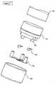
- Figure 4shows an exploded view of a torque measuring device assembly. Rotation of the part 100 in relation to the parts 101/102 will load a new dose in the dispenser 10.
- This loadingis performed by gripping the part 100 and the part 102 and rotating these elements.
- a torque sensing systemis provided between the parts 101 and 102.
- the parts 101 and 102are concentric bodies, rotatable in relation to each other, between which the torque is measured.
- the torqueis determined as one or more protrusions 201, 202 of each body, upon rotation, is forced toward each other. Between these protrusions, one or more force sensitive resistors (FSRs) 104 are positioned which provide a read-out relating to the torque.
- FSRsforce sensitive resistors
- a resilient member 103is fitted between the two bodies.
- two oppositely arranged FSRsare used for providing a bidirectional torque measurement; however, for a unidirectional torque measurement, only one FSR is required.
- Figure 5shows a cross section of the torque measuring assembly of Figure 4 .
- Figure 5illustrates the protrusions 201 and 202 on the two bodies. These protrusions transfer the torque between the two bodies and the FSR mounted in between the protrusions will convert the force to a resistor value for further electronic registration of the torque.
- this type of torque measuring devicemay be used in many other types of systems, such as: break controls in vehicles, overload controls in cranes and other lifting equipment and safety controls in general.
- this sensormay be an add-on device which may be provided with no interference with the flow characteristics and thereby the clinical approval of the dispenser. Also, the device may be detachable and reusable with several dispensers. Naturally, if this sensor is not integral with the sound/vibration sensor, communication there between may be desired in order to gather the information from the two sensors as a single processor/storage/display.
Landscapes
- Health & Medical Sciences (AREA)
- Engineering & Computer Science (AREA)
- Life Sciences & Earth Sciences (AREA)
- Animal Behavior & Ethology (AREA)
- Public Health (AREA)
- Pulmonology (AREA)
- Anesthesiology (AREA)
- Biomedical Technology (AREA)
- Heart & Thoracic Surgery (AREA)
- Hematology (AREA)
- Veterinary Medicine (AREA)
- General Health & Medical Sciences (AREA)
- Bioinformatics & Cheminformatics (AREA)
- Physics & Mathematics (AREA)
- Biophysics (AREA)
- Electromagnetism (AREA)
- Fluid Mechanics (AREA)
- General Physics & Mathematics (AREA)
- Measurement Of The Respiration, Hearing Ability, Form, And Blood Characteristics Of Living Organisms (AREA)
- Percussion Or Vibration Massage (AREA)
Abstract
Description
- The present invention relates to the field of analyzing, monitoring, logging and transmitting information on inhaler-based medication history. Such information may be used for clinical trials, where the use pattern versus prescription of an Inhaler based drug is an important parameter, or the information feedback may be displayed directly to the user to guide the user to better inhalation and compliance.
- More specifically this invention relates to a device, which may be attached to an existing inhaler without any need of intervention within the function of the inhaler. The inhalation flow is measured acoustically outside the Inhaler by means of a microphone or similar acoustic/vibration sensor. Additionally, means for measuring dose loading externally from the device will be disclosed.
- Inhalers have become wide spread for treating I. e. respiratory disorders, diabetes, osteoporosis and pain. The inhaler devices are clinically validated together with the specific drug for a specific therapy. When new issues come up that need to be clinically substantiated combined with a need of better clinical cost/benefit ratio by obtaining more reliable use pattern data from fewer test persons, or there is a need for new features like compliance feedback to the user, there is a demand for implementing electronic event data logging with inhalers. To avoid redesigning the inhalers and the associated costly clinical trials, there is a need for an add-on device, which does not imply any intervention into the inhaler, thus still logging or providing relevant reliable data regarding dose loading and inhalation flow.
US-A-5,505,195 describes an electronic device to be attached to a standard dry powder inhaler, but the description reveals that the flow sensors disclosed interfere with the mechanical design of the inhaler and will therefore not conform to the demands above.GB-2262452 US2004/0069301 andGB2398065 Wo 2005/042076 andEP-A-1480555 .- It Is an object of the present invention to provide a simple add-on electronic monitoring device to be attached to an existing conventional inhaler design without the need of changing the design and risk of changing the aerodynamic behaviour of the inhaler flow path. The monitoring device may contain acoustic sensors, detectors, control circuit, data transmission circuit, battery, display or diodes and optional circuits for indirectly detecting dose loading in the inhaler.
- In a first aspect, the invention relates to an inhaler according to
claim 1. - In the present context, an aerosol normally is a medication, such as a dry powder, suspended, in a canister, in a medium adapted for expelling the powder. A dispenser of this type often is termed a pMDI (pressurixed metered dose inhaler).
- Both the dry powder and the aerosol is inhaled by the person by the person drawing air through the inhaler and in the flow path, past the dispensing position, out the outlet and Into the lungs of the person. In this situation, the gas flow and other gas parameters may be those of the mixture of air and powder/aerosol, which is output of the output and inhaled by the person.
- Normally, the dispensing position and the flow path form parts of an overall flow path in the Inhaler from one or more air intakes, past the dispensing position and to the gas outlet which normally Is shaped so that it is easily engaged or sealed against by the lips of a person.
- The flow path is defined by surfaces, normally internal surfaces, of the dispenser, the external surface to or at which the sensing means is attached does not form part of the surfaces defining the flow path.
- The sensing means should be detachably attached to the external surface in a manner so that, if removed, no impact is made on the aerodynamic behavior or properties of the flow path. In that manner, the medical compliance of the inhaler is not affected by the presence (or absence) of the sensing means.
- The attachment may be an attachment via which the acoustic vibrations or sound travels from the external surface to the sensor (an acoustic attachment).
- It is well known from acoustics that sound travels well in most solid materials. When a user inhales the medication, the flow path within the inhaler creates a characteristic flow noise sound depending on flow rate and turbulences. Some of this sound is transmitted through the solid structure of the inhaler. As losses in the solid material are small, it is in principle possible to detect the sound anywhere on the inhaler surface. It has been found that the optimal frequency interval for such flow determination is 100-3000Hz, such as in the 600-900 Hz interval.
- A number of parameters may be interesting, depending on the medication to be inhaled and other situations such as the age or training of the person.
- One parameter is the volume of gas/air inhaled. This parameter may be used for ensuring that a sufficient amount of medication was inhaled.
- Another parameter is the flow velocity of the gas. It has been found that depending on where the medication is to be deposited (throat, lungs), the velocity of the inhaled gas/particles must be different. Thus, the flow velocity may be of Interest In the determination whether the inhalation was correct.
- Other interesting parameters may be the time during which the flow was within a certain flow velocity interval or above a certain lower limit, again to ensure that the inhalation was correct or sufficient.
- In fact, the present dispenser may also be used for estimate, on the basis of the vibrations/sound sensed, a maximum flow output from the gas outlet. Thus, a peak flow inspiratory sensor is obtained.
- The present sensor may also be used for detecting other events or features of the dispenser or the dispensing. In one situation, the sensor is used for detecting inhaler dose loading mechanism sounds. Thus, also the correct loading or the time between loadings and dispensing may be determined or logged for later evaluation.
- Even though any type of noise/sound/vibration sensor may be used, it is preferred that the present sensor is chosen from the group consisting of: a microphone, a strain gauge, a piezo element, an accelerometer, a bending sensor, capacitive sensor, a magnetic sensor, a displacement sensor, and an optical sensor.
- In order to be able to cancel out ambient noise or handling noise, in one situation, the sensor further comprises another acoustic sensor for measurement of, and in communication with the surroundings. Thus, the signal from this other sensor may be used for eliminating ambient noise or handling noise from the signal from the actual sensor.
- In another situation, the sensor comprises an ambient noise reducing acoustic sensor design, where the front of the sensor is brought into direct contact with the exterior surface of the inhaler, and where the rear side of the sensor is in direct acoustic communication with the surroundings via a port in a casing enclosing the sensor, thereby cancelling ambient noise directly in the sensor.
- A control circuit may be used for obtaining the parameters from the sensor and for calculating, estimating or determining information relating to the use of the inhaler. This information may be information relating to:
- after an inhalation, whether the inhalation was correct, such as if the duration, power consistency and frequency spectrum fulfils certain requirements,
- the time of inhalation - such as for compliance determination, or
- inhalation flow rates.
- Naturally, the information derived may be used in a number of manners. In one situation, the inhaler further has means for informing a user of one or more estimated parameters. These means may be integral with the sensing means so as to be removable from one inhaler and attachable to another, such as when one inhaler, or a powder/aerosol container thereof, is used up.
- These means may further comprise data communication means for communication with e.g. a computer or a device adapted to forward information from the inhaler/sensing means to a doctor or other person for analysis and evaluation. This information may both be information relating to a newly performed inhalation (such as for training purposes) or stored information relating to the use over a period of time, such as for statistical analysis or compliance determination.
- In a preferred embodiment, the inhaler has a dry powder container or an aerosol container and a first part defining at least part of the flow path. In that manner, the container may be replaced while maintaining the first part of the inhaler. If the first part defines all of the flow path, the aerodynamic properties thereof will change when replacing an empty container.
- In a first situation, the external surface is an outer surface of the container, whereby the sensor is removed before discarding an empty container. In another situation, the external surface is an outer surface of the first part, whereby the sensor need not be removed when replacing a container.
- The optimum position of the sensor will depend on the construction of the inhaler and the materials of which it is made. The vibrations caused by flow in the flow channel will travel through all materials but with different efficiency depending on the actual material and the construction of the inhaler. Presently, it is preferred to position the sensor in contact with a surface part which is allowed to and adapted to vibrate with a frequency in the interval of 100-3000 Hz in that the vibration of this part during a flow will amplify the sound or vibration sensed by the sensor.
- Desirably, the position of the sensing means is chosen to be one where the desired parameter (such as the flow rate) may be determined. Thus, the position may be one in which the sound or vibration is sufficiently high/large, where variations during manufacturing influence the measurements the least or below a desired limit, and/or where no or only insignificant impact on the flow path is made. Also, aesthetics and ergonomics may be taken into account when determining the position.
- Another aspect of the invention relates to a method of operating the above inhaler, the method comprising sensing vibration(s) or sound with one or more frequencies within the interval of 100-3000 Hz and, estimating, on the basis of the sensed vibration/sound, a parameter of a flow in the flow path.
- One such estimated parameter may be a volume of gas output from the gas outlet. The strength or amplitude of the sound/vibration, such as at one or more frequencies or frequency intervals, is dependent on the flow (volume per time unit) of the gas/air flowing. Thus, the flow may be determined rather simply.
- Another such parameter may be a maximum flow output from the gas outlet. Thus, the above-mentioned peak flow inspiratory sensor may be obtained.
- A third such parameter may be a period of time during which a predetermined flow has existed. Thus, it may be determined for how long, during a dispensation, the flow was over a certain threshold or within a predetermined flow interval.
- The method may also comprise informing a user of one or more estimated parameters. This may be in order to train the person, inform the person of a compliance read-out, when the last inhalation took place, when the next inhalation should take place, how the person's peak inhalation flow has evolved, or the like.
- Naturally, the sensing means for use in the first aspect of the invention may be adapted to perform all the above relevant operations, may be positionable at any desired position on the inhaler and may be attachable in any manner:
- In the following, preferred embodiments of the present invention are illustrated by reference to the drawing, wherein:
Figure 1 illustrates a cross section of a first embodiment of an inhaler with a sensor,Figure 2 illustrates a cross section of a second embodiment of an inhaler with a sensor,Figure 3 illustrates the variation of a sound spectrum with flow rate,Figure 4 illustrates an interesting manner of determining a torque between two elements,Figure 5 illustrates a cross section through the embodiment ofFigure 4 .Figure 1 illustrates a cross section through a first embodiment of aninhaler 10, which may be any inhaler, such as the Diskus®(GSK), Technohaler® (Innovata Biomed), D2L® (Ivax), Turbuhaler® (AstraZeneca), SkyeHaler DPI® (SkyePharma), Easi-Breathe DPI® (IVAX), Pulvinal® (Chiesl), EasyHaler® (Orion Farmos), Clickhaler® (Innovata Blomed), Talfun® (Focus Inhale), or the Ultrahaler® (Aventis). At the bottom (or at any other suitable position), asensor assembly 12 is provided which comprises anelement 14 holding amicrophone 16 and which is fastened via afastening clip 18 to the bottom of theinhaler 10.- Between the
element 14 and the bottom, aresilient element 20 is provided for sealing airborne noise from the surroundings away from themicrophone 16. - The space defined by the bottom, the
element 20 and theelement 14 forms a closed acoustic coupling volume between themicrophone 16 and the inhaler, where the bottom acts as a "drum skin" and vibrates in a manner so that themicrophone 16 may detect the vibration. - In another embodiment, a second microphone is coupled to the surroundings in order to sense/detect the ambient noise in order to cancel out a potential ambient noise component in the signal from the first microphone and thereby achieve a detector system that is more robust to ambient noise sources present in the environment of the user during daily life situations.
Figure 2 illustrates a cross section through a second embodiment of an inhaler 10' having asensor 12' as seen inEP-A-1480555 , "A transducer for bio-acoustic signals", which discloses a contact sensor 16' with afront side 23 and arear side 22, thefront side 23 being in solid communication with the source of sound (in this application the inhaler) and therear side 22 being in communication with the surroundings through aport 24 in the sensor cover 14', saidport 24 and cover 14' constituting an acoustic impedance that can optimize the ambient noise cancelling within thesensor 12'.- In general, the
sensor 12/12' may be attached to the inhaler by theclip 18 and be removed there from such as to be attached to anotherdispenser 10/10'. It is also seen that the operation of thesensor 12/12' makes no impact on the flow path defined within thedispenser 10/10'. - The detected or sensed sound/vibration spectrum varies with the flow rate in the inhaler. In
Figure 3 , results of experiments illustrate that the power/amplitude of sound at frequencies in the interval of 100-1000 Hz (Low range) essentially has a linear dependency with flow rate and the power of sound at frequencies in the interval of 1000-5000 Hz (High range) has an essentially non-linear dependency with flow rate caused by increased turbulences and "whistle phenomena". Handling noise is prominent in the low range of the frequency spectrum. - Thus, preferably, a method is devised for determining whether the noise/vibration/sound sensed relates to an inhalation or not. Numerous manners exist, one of which will be described in detail:
- Preferably, the signal output from the sensor is filtered in order to obtain signal amplitude within particular frequency bands which are especially suitable for the individual dispenser. For e.g. the AstraZeneca TurbuHaler three frequency bands are used: X1: 600-900 Hz, X2: 2200-2280 Hz, and X3: 3500-5000 Hz.
Figure 3 illustrates an experiment demonstrating the relationship between the inhalation flow in the mouthpiece of the dry powder inhaler and the associated structural acceleration picked up by the monitoring device. The inhaler is the AstraZeneca TurbuHaler and the acoustic sensing monitors the bottom plate vibration signal. A person now inhales at five times in succession (varying from 'very weak', 'weak', 'normal', 'strong' and 'very strong' inhalation where 'normal' approximately equals a flow rate of 30 l/min). As seen from the Intensity/time plot the overall level of the vibrational signal follows the flow rate. Furthermore from the time/frequency plot it can be seen that the energy is not equally strong at all Individual frequencies but follows structural resonances e.g. in the inhaler bottom plate mechanics.- In order to make sure that an inhalation takes place, the signals in all three bands is constantly logged, and when the signal energy in X3 exceeds that of X2 by a predetermined amount, and when the signal energy in X3 is above a predetermined threshold, an inhalation is assumed to take place, and the signal in X1 is logged and assumed to relate to a flow.
- The actual flow relates to the energy in the X1 interval, whereby a determination of the actual flow, total volume inhaled, etc, is easy.
- It may also be required that the flow (energy in X1) exceeds a predetermined threshold, before an inhalation is assumed to take place, and all three requirements may be required to take place simultaneously and continuously for a period of time, such as ½ second, before an inhalation is assumed to take place. In addition, if the requirements are fulfilled for a too long period of time, such as if the noise may be caused by e.g. an airplane, a vacuum cleaner or the like, the logging and measuring may be stopped and assumed invalid.
- Naturally, any other manner of determining that an inhalation takes place may be used, such as manners based on more elaborate signal analysis adapted to e.g. detect an inhalation from a long-lasting (such as one or more seconds) relatively constant signal as compared to short-lasting handling noise. Also, other means may be required (such as rudimentary flow sensors already provided in the dispenser) for determining that an inhalation takes place and for trigging a flow measurement.
- If necessary, further qualifying conditions may be set up to check for frequency balance between low and high frequency range.
- Having thus obtained information relating to the flow, different parameters may be obtained.
- The energy in the X1 interval describes the flow over time. Thus, from the period of time in which the flow is within a predetermined flow interval or exceeds a predetermined minimum flow, a quality of the inhalation may be derived, the amount of medication inhaled may be determined, or the volume of air/gas inhaled may be derived.
- The volume of air/gas inhaled may also be derived on the basis of the full inhalation with no lower or upper limit for the gas flow.
- The quality of an inhalation may be derived from the period of time during which the optimal flow is detected. Both a too low and a too high flow may be detrimental to this quality.
- Also, the highest inhalation flow (peak inspiratory flow) may be determined from the sensed flow.
- Naturally, any parameter sensed or determined may be read out to the user using a display, e.g. (not illustrated). Thus, the quality of the inhalation, the number of inhalations, compliance to a determined inhalation scheme, point in time of last or next inhalation, or similar information may be given to the person, such as quantified or qualified, in order for the user to easily see whether the inhalation or compliance is acceptable.
- Also or alternatively, this information may be stored for later reading by e.g. clinical staff. This reading may be via wired or wireless communication (blue tooth, wireless, Ethernet, etc., etc.).
- The sensor may also be used for additional detections. In one example, if the inhaler loader mechanism produces a characteristic acoustic signal/noise when activated, the above acoustic sensor systems may be used to detect a dose loading event that may be logged.
- Thus, the time of loading may be compared to the time of inhalation, which may be interesting in some embodiments. Also, the user may be informed that a dose is loaded, and these points in time may be stored and read out for analysis of the compliance and behaviour of the person.
- Naturally, the detection system may be combined with other types of sensors, such as an indirect dose loading detector, which may be a detector detecting a torque exerted between two parts of the inhaler body, which two parts are griped by the user when rotating two parts of the Inhaler in relation to each other to load a next dose.
Figure 4 shows an exploded view of a torque measuring device assembly. Rotation of thepart 100 in relation to theparts 101/102 will load a new dose in thedispenser 10.- This loading is performed by gripping the
part 100 and thepart 102 and rotating these elements. Between theparts parts - The torque is determined as one or
more protrusions - To virtually avoid play between the two bodies, when assembled, without the risk of introducing friction between the bodies that could result in biasing the torque measurements, a
resilient member 103 is fitted between the two bodies. In the present embodiment, two oppositely arranged FSRs are used for providing a bidirectional torque measurement; however, for a unidirectional torque measurement, only one FSR is required. Figure 5 shows a cross section of the torque measuring assembly ofFigure 4 .Figure 5 illustrates theprotrusions - Naturally, this type of torque measuring device may be used in many other types of systems, such as: break controls in vehicles, overload controls in cranes and other lifting equipment and safety controls in general.
- In relation to the powder dispenser, as is the situation with the sound/vibration sensor, this sensor may be an add-on device which may be provided with no interference with the flow characteristics and thereby the clinical approval of the dispenser. Also, the device may be detachable and reusable with several dispensers. Naturally, if this sensor is not integral with the sound/vibration sensor, communication there between may be desired in order to gather the information from the two sensors as a single processor/storage/display.
Claims (13)
- An inhaler (10, 10') comprising an external surface and:- means for dispensing an aerosol or a dry powder at a dispensing position,- means for defining a flow path between the dispensing position and a gas outlet, and- sensing means (12, 12') detachably attached to the external surface,characterised in that the sensing means is adapted to sense vibrations or sound wit a frequency in the interval of 100-3000 Hz and estimate, on the basis of the vibrations/sound sensed in the interval of 100-3000 Hz, a parameter of a flow in the flow path.
- An inhaler according to claim 1, wherein the sensing means is adapted to estimate, as the parameter, a volume of gas output from the gas outlet.
- An inhaler according to claim 1, wherein the sensing means is adapted to estimate, as the parameter, a maximum flow output from the gas outlet.
- An inhaler according to claim 1, wherein the sensing means chosen from the group consisting of: a microphone, a strain gauge, a piezo element, an accelerometer, a bending sensor, capacitive sensor, a magnetic sensor, a displacement sensor, and an optical sensor.
- An inhaler according to claim 1, further comprising means for informing a user of one or more estimated parameters.
- An inhaler according to claim 1, the inhaler comprising a dry powder container or an aerosol container and a first part defining at least part of the flow path.
- An inhaler according to claim 6, wherein the external surface is an outer surface of the container.
- An inhaler according to claim 6, wherein the external surface is an outer surface of the first part.
- A method of operating an inhaler according to claim 1, the method comprising sensing vibration(s) or sound with one or more frequencies within the interval of 100-3000 Hz, and estimating, on the basis of the sensed vibration/sound, a parameter of a flow in the flow path.
- A method according to claim 9, comprising estimating, as the parameter, a volume of gas output from the gas outlet.
- A method according to claim 9, comprising estimating, as the parameter, a maximum flow output from the gas outlet.
- A method according to claim 9, comprising estimating, as the parameter, a period of time during which a predetermined flow has existed.
- A method according to claim 9, further comprising the step of informing a user of one or more estimated parameters.
Applications Claiming Priority (3)
| Application Number | Priority Date | Filing Date | Title |
|---|---|---|---|
| DKPA200600331 | 2006-03-07 | ||
| DKPA200600548 | 2006-04-20 | ||
| PCT/DK2007/000101WO2007101438A1 (en) | 2006-03-07 | 2007-02-28 | Acoustic inhaler flow measurement |
Publications (2)
| Publication Number | Publication Date |
|---|---|
| EP1993642A1 EP1993642A1 (en) | 2008-11-26 |
| EP1993642B1true EP1993642B1 (en) | 2012-01-11 |
Family
ID=38024185
Family Applications (1)
| Application Number | Title | Priority Date | Filing Date |
|---|---|---|---|
| EP07711252AActiveEP1993642B1 (en) | 2006-03-07 | 2007-02-28 | Acoustic inhaler flow measurement |
Country Status (4)
| Country | Link |
|---|---|
| US (1) | US9242056B2 (en) |
| EP (1) | EP1993642B1 (en) |
| AT (1) | ATE540715T1 (en) |
| WO (1) | WO2007101438A1 (en) |
Cited By (7)
| Publication number | Priority date | Publication date | Assignee | Title |
|---|---|---|---|---|
| US10850050B2 (en) | 2016-05-19 | 2020-12-01 | Trudell Medical International | Smart valved holding chamber |
| US10881818B2 (en) | 2016-07-08 | 2021-01-05 | Trudell Medical International | Smart oscillating positive expiratory pressure device |
| US10894142B2 (en) | 2016-03-24 | 2021-01-19 | Trudell Medical International | Respiratory care system with electronic indicator |
| USD910163S1 (en) | 2018-01-04 | 2021-02-09 | Trudell Medical International | Oscillating positive expiratory pressure device, adapter and control module assembly |
| US11395890B2 (en) | 2018-06-04 | 2022-07-26 | Trudell Medical International | Smart valved holding chamber |
| US11497867B2 (en) | 2016-12-09 | 2022-11-15 | Trudell Medical International | Smart nebulizer |
| US11712175B2 (en) | 2019-08-27 | 2023-08-01 | Trudell Medical International | Smart oscillating positive expiratory pressure device with feedback indicia |
Families Citing this family (64)
| Publication number | Priority date | Publication date | Assignee | Title |
|---|---|---|---|---|
| US11647783B2 (en) | 2005-07-19 | 2023-05-16 | Juul Labs, Inc. | Devices for vaporization of a substance |
| US20160345631A1 (en) | 2005-07-19 | 2016-12-01 | James Monsees | Portable devices for generating an inhalable vapor |
| DE102007039581A1 (en)* | 2007-08-22 | 2009-02-26 | Fresenius Medical Care Deutschland Gmbh | Apparatus and method for monitoring access to a patient |
| DE102008002028A1 (en)* | 2008-05-28 | 2009-12-03 | Endress + Hauser Flowtec Ag | Measuring cell for use in measuring device for ultrasonic pressure flow measuring system, has molded part for adjustment of measuring cell at measuring device |
| DE102008002027A1 (en)* | 2008-05-28 | 2009-12-03 | Endress + Hauser Flowtec Ag | Measuring cell for use in measuring device of ultrasonic measuring system, has molded part provided with surface for coupling and/or decoupling of ultrasonic signal for determining flow-through of fluid medium through cell |
| GB201006901D0 (en)* | 2010-04-26 | 2010-06-09 | Sagentia Ltd | Device for monitoring status and use of an inhalation or nasal drug delivery device |
| US9492068B2 (en) | 2010-06-04 | 2016-11-15 | The United States Of America, As Represented By The Secretary, Department Of Health And Human Services | Nasal aerosol delivery system |
| MX355950B (en)* | 2011-03-15 | 2018-05-07 | Novartis Ag | Inhaler. |
| KR102177660B1 (en) | 2011-08-16 | 2020-11-12 | 쥴 랩스, 인크. | Low temperature electronic vaporization device and methods |
| GB2502055A (en) | 2012-05-14 | 2013-11-20 | Nicoventures Holdings Ltd | Modular electronic smoking device |
| ES2988402T3 (en) | 2012-06-25 | 2024-11-20 | Gecko Health Innovations Inc | Devices, systems and methods for monitoring therapeutic compliance and patient interaction |
| US10029056B2 (en) | 2012-08-29 | 2018-07-24 | The Provost, Fellows, Foundation Scholars, & The Other Members Of Board, Of The College Of The Holy & Undivided Trinity Of Queen Elizabeth Near Dublin | System and method for monitoring use of a device |
| US10258753B2 (en) | 2012-10-04 | 2019-04-16 | Boehringer Ingelheim International Gmbh | System, method, use and information storage medium for practicing of an inhalation process |
| GB2507104A (en) | 2012-10-19 | 2014-04-23 | Nicoventures Holdings Ltd | Electronic inhalation device |
| GB2507103A (en) | 2012-10-19 | 2014-04-23 | Nicoventures Holdings Ltd | Electronic inhalation device |
| US11052202B2 (en)* | 2012-11-07 | 2021-07-06 | Chiesi Farmaceutici S.P.A. | Drug delivery device for the treatment of patients with respiratory diseases |
| WO2016049066A1 (en)* | 2014-09-23 | 2016-03-31 | Oscillari Llc | Vibration sensor based drug delivery monitor |
| EP3019081A4 (en)* | 2013-07-12 | 2018-04-25 | Oscillari LLC | Acoustic based drug delivery monitor |
| MX358899B (en) | 2013-08-28 | 2018-09-07 | Gecko Health Innovations Inc | DEVICES, SYSTEMS AND METHODS FOR MONITORING ADHERENCE AND DEVICES, SYSTEMS AND METHODS TO MONITOR THE USE OF CONSUMABLES DISPENSERS. |
| GB2519101A (en) | 2013-10-09 | 2015-04-15 | Nicoventures Holdings Ltd | Electronic vapour provision system |
| US10058129B2 (en) | 2013-12-23 | 2018-08-28 | Juul Labs, Inc. | Vaporization device systems and methods |
| US10159282B2 (en) | 2013-12-23 | 2018-12-25 | Juul Labs, Inc. | Cartridge for use with a vaporizer device |
| DE202014011260U1 (en) | 2013-12-23 | 2018-11-13 | Juul Labs Uk Holdco Limited | Systems for an evaporation device |
| US10076139B2 (en) | 2013-12-23 | 2018-09-18 | Juul Labs, Inc. | Vaporizer apparatus |
| USD842536S1 (en) | 2016-07-28 | 2019-03-05 | Juul Labs, Inc. | Vaporizer cartridge |
| US20160366947A1 (en) | 2013-12-23 | 2016-12-22 | James Monsees | Vaporizer apparatus |
| DK3113817T3 (en)* | 2014-03-03 | 2021-02-01 | Adherium Nz Ltd | MONITORING MONITOR FOR A DEVICE FOR ADMINISTRATION OF DRUGS IN DRY POWDER FORM |
| CN106132465B (en)* | 2014-03-25 | 2019-09-24 | 皇家飞利浦有限公司 | Inhaler with two microphones for detection of inspiratory flow |
| AU2015245626B2 (en) | 2014-04-07 | 2019-10-31 | Boehringer Ingelheim International Gmbh | Inhalation training device and system for practicing of an inhalation process of a patient |
| WO2015154864A2 (en) | 2014-04-07 | 2015-10-15 | Boehringer Ingelheim International Gmbh | Method, electronic device, inhalation training system and information storage medium for practicing and/or controlling an inhalation process of a patient |
| CA160775S (en) | 2014-08-11 | 2015-09-29 | Ploom Inc | Electronic vaporization device with cartridge |
| CN106714880B (en) | 2014-08-28 | 2021-12-03 | 诺顿(沃特福特)有限公司 | Compliance monitoring module for breath-actuated inhaler |
| CA2958891A1 (en) | 2014-08-28 | 2016-03-03 | Microdose Therapeutx, Inc. | Tidal dry powder inhaler with miniature pressure sensor activation |
| IL316543A (en) | 2014-08-28 | 2024-12-01 | Norton Waterford Ltd | Compliance Monitoring Unit for Inhaler |
| JP2017527415A (en)* | 2014-09-15 | 2017-09-21 | アドヘリウム (エヌゼット) リミテッド | Adherence monitor for dry powder drug delivery devices |
| GB201420039D0 (en) | 2014-11-11 | 2014-12-24 | Teva Uk Ltd | System for training a user in administering a medicament |
| US10058661B2 (en) | 2014-12-04 | 2018-08-28 | Norton (Waterford) Limited | Inhalation monitoring system and method |
| MX394125B (en) | 2014-12-05 | 2025-03-24 | Juul Labs Inc | CALIBRATED DOSE CONTROL |
| EP3247277A1 (en) | 2015-01-23 | 2017-11-29 | Sandoz AG | An apparatus and method for producing a flow profile |
| GB2540135B (en) | 2015-07-01 | 2021-03-03 | Nicoventures Holdings Ltd | Electronic aerosol provision system |
| PL3111978T3 (en)* | 2015-07-03 | 2022-01-24 | Novartis Ag | Inhaler adapted to read information stored in a data storage means of a container |
| RU2738578C2 (en) | 2015-07-20 | 2020-12-14 | Перл Терапьютикс, Инк. | Aerosol delivery systems and corresponding methods |
| SI3199193T1 (en)* | 2016-01-28 | 2020-12-31 | Novartis Ag | Method for measuring flow features in an inhaler, inhaler and system |
| EP3203397B1 (en)* | 2016-02-08 | 2020-04-01 | PARI Pharma GmbH | Medical evaluation device |
| CO2018009342A2 (en) | 2016-02-11 | 2018-09-20 | Juul Labs Inc | Secure fixing cartridges for vaporizing devices |
| CN114588435A (en)* | 2016-05-19 | 2022-06-07 | 曼金德公司 | Devices, systems and methods for detecting and monitoring inhalation |
| WO2017205824A1 (en) | 2016-05-27 | 2017-11-30 | Proveris Scientific Corporation | Devices and methods for using medicament devices |
| USD849996S1 (en) | 2016-06-16 | 2019-05-28 | Pax Labs, Inc. | Vaporizer cartridge |
| USD851830S1 (en) | 2016-06-23 | 2019-06-18 | Pax Labs, Inc. | Combined vaporizer tamp and pick tool |
| USD836541S1 (en) | 2016-06-23 | 2018-12-25 | Pax Labs, Inc. | Charging device |
| GB2552457B (en)* | 2016-06-29 | 2019-02-27 | Cambridge Medtech Solutions Ltd | Method and apparatus for assisting drug delivery |
| CN114177442A (en) | 2016-11-18 | 2022-03-15 | 诺顿(沃特福特)有限公司 | Drug delivery device with electronics |
| JP7014791B2 (en) | 2016-11-18 | 2022-02-01 | ノートン (ウォーターフォード) リミテッド | Inhaler |
| IT201700086905A1 (en)* | 2017-07-28 | 2019-01-28 | Amiko S R L | Accessory for inhaler, inhaler and method for detecting a drug administration process |
| USD887632S1 (en) | 2017-09-14 | 2020-06-16 | Pax Labs, Inc. | Vaporizer cartridge |
| GB2570439A (en)* | 2017-12-13 | 2019-07-31 | British American Tobacco Investments Ltd | Method and apparatus for analysing user interaction |
| CN109908442A (en)* | 2019-01-25 | 2019-06-21 | 苏州艾莱科劢德电子科技有限公司 | A kind of flow velocity arrangement for detecting of the Diskus based on sound |
| AU2020264799A1 (en) | 2019-04-30 | 2021-11-25 | Norton (Waterford) Limited | Inhaler system |
| US11419995B2 (en) | 2019-04-30 | 2022-08-23 | Norton (Waterford) Limited | Inhaler system |
| CA3140949A1 (en) | 2019-05-17 | 2020-11-26 | Norton (Waterford) Limited | Drug delivery device with electronics |
| IT201900017417A1 (en)* | 2019-09-27 | 2021-03-27 | Amiko S R L | Dry powder inhaler for nasal or pulmonary administration |
| MX2022007103A (en) | 2019-12-10 | 2022-09-02 | Trudell Medical Int | Integrated dose counter. |
| GB202010619D0 (en)* | 2020-07-10 | 2020-08-26 | Nicoventures Holdings Ltd | Aerosol provision device and aerosol provision system |
| EP4599873A1 (en) | 2024-02-06 | 2025-08-13 | PLASTIAPE S.p.A. | Accessories for inhalers |
Family Cites Families (10)
| Publication number | Priority date | Publication date | Assignee | Title |
|---|---|---|---|---|
| GB2262452B (en) | 1991-12-19 | 1995-12-20 | Minnesota Mining & Mfg | Inhalation device |
| US5819726A (en)* | 1993-01-29 | 1998-10-13 | Aradigm Corporation | Method for the delivery of aerosolized drugs to the lung for the treatment of respiratory disease |
| US5505195A (en) | 1993-09-16 | 1996-04-09 | Medtrac Technologies Inc. | Dry powder inhalant device with dosage and air flow monitor |
| US5929875A (en)* | 1996-07-24 | 1999-07-27 | Hewlett-Packard Company | Acoustic and ultrasonic monitoring of inkjet droplets |
| WO2002058771A1 (en) | 2001-01-25 | 2002-08-01 | Clinical Designs Limited | Dispenser for medicament |
| MXPA04007016A (en)* | 2002-01-23 | 2005-11-10 | Bang & Olufsen Medicom As | A blood pressure measuring device with a cuff of two openable concave shell parts. |
| JP2005533581A (en)* | 2002-07-25 | 2005-11-10 | グラクソ グループ リミテッド | Drug dispenser |
| GB0322284D0 (en)* | 2003-09-23 | 2003-10-22 | Glaxo Group Ltd | Medicament dispenser |
| GB2398065A (en) | 2003-10-16 | 2004-08-11 | Bespak Plc | Dispensing apparatus |
| CA2554005C (en)* | 2004-02-24 | 2013-05-28 | Microdose Technologies, Inc. | Directional flow sensor inhaler |
- 2007
- 2007-02-28EPEP07711252Apatent/EP1993642B1/enactiveActive
- 2007-02-28WOPCT/DK2007/000101patent/WO2007101438A1/enactiveApplication Filing
- 2007-02-28ATAT07711252Tpatent/ATE540715T1/enactive
- 2007-02-28USUS12/224,222patent/US9242056B2/enactiveActive
Cited By (15)
| Publication number | Priority date | Publication date | Assignee | Title |
|---|---|---|---|---|
| US10894142B2 (en) | 2016-03-24 | 2021-01-19 | Trudell Medical International | Respiratory care system with electronic indicator |
| US12383695B2 (en) | 2016-03-24 | 2025-08-12 | Trudell Medical International Inc. | Respiratory care system with electronic indicator |
| US11975140B2 (en) | 2016-05-19 | 2024-05-07 | Trudell Medical International | Medication delivery system with mask |
| US10850050B2 (en) | 2016-05-19 | 2020-12-01 | Trudell Medical International | Smart valved holding chamber |
| US11839716B2 (en) | 2016-07-08 | 2023-12-12 | Trudell Medical International | Smart oscillating positive expiratory pressure device |
| US10881818B2 (en) | 2016-07-08 | 2021-01-05 | Trudell Medical International | Smart oscillating positive expiratory pressure device |
| US11497867B2 (en) | 2016-12-09 | 2022-11-15 | Trudell Medical International | Smart nebulizer |
| US11666801B2 (en) | 2018-01-04 | 2023-06-06 | Trudell Medical International | Smart oscillating positive expiratory pressure device |
| US11964185B2 (en) | 2018-01-04 | 2024-04-23 | Trudell Medical International | Smart oscillating positive expiratory pressure device |
| US12214252B2 (en) | 2018-01-04 | 2025-02-04 | Trudell Medical International Inc. | Smart oscillating positive expiratory pressure device |
| USD910163S1 (en) | 2018-01-04 | 2021-02-09 | Trudell Medical International | Oscillating positive expiratory pressure device, adapter and control module assembly |
| US11850355B2 (en) | 2018-06-04 | 2023-12-26 | Trudell Medical International | Smart valved holding chamber |
| US11395890B2 (en) | 2018-06-04 | 2022-07-26 | Trudell Medical International | Smart valved holding chamber |
| US12427272B2 (en) | 2018-06-04 | 2025-09-30 | Trudell Medical International Inc. | Smart valved holding chamber |
| US11712175B2 (en) | 2019-08-27 | 2023-08-01 | Trudell Medical International | Smart oscillating positive expiratory pressure device with feedback indicia |
Also Published As
| Publication number | Publication date |
|---|---|
| ATE540715T1 (en) | 2012-01-15 |
| US20090308387A1 (en) | 2009-12-17 |
| US9242056B2 (en) | 2016-01-26 |
| WO2007101438A1 (en) | 2007-09-13 |
| EP1993642A1 (en) | 2008-11-26 |
Similar Documents
| Publication | Publication Date | Title |
|---|---|---|
| EP1993642B1 (en) | Acoustic inhaler flow measurement | |
| JP6931108B2 (en) | Compliance monitoring module for breath-actuated inhalers | |
| JP6957520B2 (en) | Holding chamber with smart valve | |
| EP2859906B1 (en) | Drug delivery device | |
| US10905356B2 (en) | Compliance monitoring module for an inhaler | |
| KR20170047321A (en) | Tidal dry powder inhaler with miniature pressure sensor activation | |
| HK40003336A (en) | Compliance monitoring module for a breath-actuated inhaler | |
| HK40003336B (en) | Compliance monitoring module for a breath-actuated inhaler |
Legal Events
| Date | Code | Title | Description |
|---|---|---|---|
| PUAI | Public reference made under article 153(3) epc to a published international application that has entered the european phase | Free format text:ORIGINAL CODE: 0009012 | |
| 17P | Request for examination filed | Effective date:20081007 | |
| AK | Designated contracting states | Kind code of ref document:A1 Designated state(s):AT BE BG CH CY CZ DE DK EE ES FI FR GB GR HU IE IS IT LI LT LU LV MC NL PL PT RO SE SI SK TR | |
| GRAP | Despatch of communication of intention to grant a patent | Free format text:ORIGINAL CODE: EPIDOSNIGR1 | |
| DAX | Request for extension of the european patent (deleted) | ||
| GRAS | Grant fee paid | Free format text:ORIGINAL CODE: EPIDOSNIGR3 | |
| GRAA | (expected) grant | Free format text:ORIGINAL CODE: 0009210 | |
| AK | Designated contracting states | Kind code of ref document:B1 Designated state(s):AT BE BG CH CY CZ DE DK EE ES FI FR GB GR HU IE IS IT LI LT LU LV MC NL PL PT RO SE SI SK TR | |
| REG | Reference to a national code | Ref country code:GB Ref legal event code:FG4D | |
| REG | Reference to a national code | Ref country code:CH Ref legal event code:EP | |
| REG | Reference to a national code | Ref country code:AT Ref legal event code:REF Ref document number:540715 Country of ref document:AT Kind code of ref document:T Effective date:20120115 | |
| REG | Reference to a national code | Ref country code:IE Ref legal event code:FG4D | |
| REG | Reference to a national code | Ref country code:DE Ref legal event code:R096 Ref document number:602007019964 Country of ref document:DE Effective date:20120308 | |
| REG | Reference to a national code | Ref country code:SE Ref legal event code:TRGR | |
| REG | Reference to a national code | Ref country code:NL Ref legal event code:VDEP Effective date:20120111 | |
| PG25 | Lapsed in a contracting state [announced via postgrant information from national office to epo] | Ref country code:SI Free format text:LAPSE BECAUSE OF FAILURE TO SUBMIT A TRANSLATION OF THE DESCRIPTION OR TO PAY THE FEE WITHIN THE PRESCRIBED TIME-LIMIT Effective date:20120111 | |
| LTIE | Lt: invalidation of european patent or patent extension | Effective date:20120111 | |
| PG25 | Lapsed in a contracting state [announced via postgrant information from national office to epo] | Ref country code:BG Free format text:LAPSE BECAUSE OF FAILURE TO SUBMIT A TRANSLATION OF THE DESCRIPTION OR TO PAY THE FEE WITHIN THE PRESCRIBED TIME-LIMIT Effective date:20120411 Ref country code:LT Free format text:LAPSE BECAUSE OF FAILURE TO SUBMIT A TRANSLATION OF THE DESCRIPTION OR TO PAY THE FEE WITHIN THE PRESCRIBED TIME-LIMIT Effective date:20120111 Ref country code:NL Free format text:LAPSE BECAUSE OF FAILURE TO SUBMIT A TRANSLATION OF THE DESCRIPTION OR TO PAY THE FEE WITHIN THE PRESCRIBED TIME-LIMIT Effective date:20120111 Ref country code:BE Free format text:LAPSE BECAUSE OF FAILURE TO SUBMIT A TRANSLATION OF THE DESCRIPTION OR TO PAY THE FEE WITHIN THE PRESCRIBED TIME-LIMIT Effective date:20120111 Ref country code:IS Free format text:LAPSE BECAUSE OF FAILURE TO SUBMIT A TRANSLATION OF THE DESCRIPTION OR TO PAY THE FEE WITHIN THE PRESCRIBED TIME-LIMIT Effective date:20120511 | |
| PG25 | Lapsed in a contracting state [announced via postgrant information from national office to epo] | Ref country code:LV Free format text:LAPSE BECAUSE OF FAILURE TO SUBMIT A TRANSLATION OF THE DESCRIPTION OR TO PAY THE FEE WITHIN THE PRESCRIBED TIME-LIMIT Effective date:20120111 Ref country code:GR Free format text:LAPSE BECAUSE OF FAILURE TO SUBMIT A TRANSLATION OF THE DESCRIPTION OR TO PAY THE FEE WITHIN THE PRESCRIBED TIME-LIMIT Effective date:20120412 Ref country code:FI Free format text:LAPSE BECAUSE OF FAILURE TO SUBMIT A TRANSLATION OF THE DESCRIPTION OR TO PAY THE FEE WITHIN THE PRESCRIBED TIME-LIMIT Effective date:20120111 Ref country code:PT Free format text:LAPSE BECAUSE OF FAILURE TO SUBMIT A TRANSLATION OF THE DESCRIPTION OR TO PAY THE FEE WITHIN THE PRESCRIBED TIME-LIMIT Effective date:20120511 Ref country code:PL Free format text:LAPSE BECAUSE OF FAILURE TO SUBMIT A TRANSLATION OF THE DESCRIPTION OR TO PAY THE FEE WITHIN THE PRESCRIBED TIME-LIMIT Effective date:20120111 | |
| REG | Reference to a national code | Ref country code:AT Ref legal event code:MK05 Ref document number:540715 Country of ref document:AT Kind code of ref document:T Effective date:20120111 | |
| PG25 | Lapsed in a contracting state [announced via postgrant information from national office to epo] | Ref country code:CY Free format text:LAPSE BECAUSE OF FAILURE TO SUBMIT A TRANSLATION OF THE DESCRIPTION OR TO PAY THE FEE WITHIN THE PRESCRIBED TIME-LIMIT Effective date:20120111 Ref country code:MC Free format text:LAPSE BECAUSE OF NON-PAYMENT OF DUE FEES Effective date:20120229 | |
| REG | Reference to a national code | Ref country code:CH Ref legal event code:PL | |
| PG25 | Lapsed in a contracting state [announced via postgrant information from national office to epo] | Ref country code:LI Free format text:LAPSE BECAUSE OF NON-PAYMENT OF DUE FEES Effective date:20120229 Ref country code:EE Free format text:LAPSE BECAUSE OF FAILURE TO SUBMIT A TRANSLATION OF THE DESCRIPTION OR TO PAY THE FEE WITHIN THE PRESCRIBED TIME-LIMIT Effective date:20120111 Ref country code:RO Free format text:LAPSE BECAUSE OF FAILURE TO SUBMIT A TRANSLATION OF THE DESCRIPTION OR TO PAY THE FEE WITHIN THE PRESCRIBED TIME-LIMIT Effective date:20120111 Ref country code:CZ Free format text:LAPSE BECAUSE OF FAILURE TO SUBMIT A TRANSLATION OF THE DESCRIPTION OR TO PAY THE FEE WITHIN THE PRESCRIBED TIME-LIMIT Effective date:20120111 Ref country code:DK Free format text:LAPSE BECAUSE OF FAILURE TO SUBMIT A TRANSLATION OF THE DESCRIPTION OR TO PAY THE FEE WITHIN THE PRESCRIBED TIME-LIMIT Effective date:20120111 Ref country code:CH Free format text:LAPSE BECAUSE OF NON-PAYMENT OF DUE FEES Effective date:20120229 | |
| PLBE | No opposition filed within time limit | Free format text:ORIGINAL CODE: 0009261 | |
| STAA | Information on the status of an ep patent application or granted ep patent | Free format text:STATUS: NO OPPOSITION FILED WITHIN TIME LIMIT | |
| REG | Reference to a national code | Ref country code:IE Ref legal event code:MM4A | |
| PG25 | Lapsed in a contracting state [announced via postgrant information from national office to epo] | Ref country code:IT Free format text:LAPSE BECAUSE OF FAILURE TO SUBMIT A TRANSLATION OF THE DESCRIPTION OR TO PAY THE FEE WITHIN THE PRESCRIBED TIME-LIMIT Effective date:20120111 Ref country code:SK Free format text:LAPSE BECAUSE OF FAILURE TO SUBMIT A TRANSLATION OF THE DESCRIPTION OR TO PAY THE FEE WITHIN THE PRESCRIBED TIME-LIMIT Effective date:20120111 | |
| 26N | No opposition filed | Effective date:20121012 | |
| PG25 | Lapsed in a contracting state [announced via postgrant information from national office to epo] | Ref country code:IE Free format text:LAPSE BECAUSE OF NON-PAYMENT OF DUE FEES Effective date:20120228 Ref country code:AT Free format text:LAPSE BECAUSE OF FAILURE TO SUBMIT A TRANSLATION OF THE DESCRIPTION OR TO PAY THE FEE WITHIN THE PRESCRIBED TIME-LIMIT Effective date:20120111 | |
| REG | Reference to a national code | Ref country code:DE Ref legal event code:R097 Ref document number:602007019964 Country of ref document:DE Effective date:20121012 | |
| PG25 | Lapsed in a contracting state [announced via postgrant information from national office to epo] | Ref country code:ES Free format text:LAPSE BECAUSE OF FAILURE TO SUBMIT A TRANSLATION OF THE DESCRIPTION OR TO PAY THE FEE WITHIN THE PRESCRIBED TIME-LIMIT Effective date:20120422 | |
| PG25 | Lapsed in a contracting state [announced via postgrant information from national office to epo] | Ref country code:TR Free format text:LAPSE BECAUSE OF FAILURE TO SUBMIT A TRANSLATION OF THE DESCRIPTION OR TO PAY THE FEE WITHIN THE PRESCRIBED TIME-LIMIT Effective date:20120111 | |
| PG25 | Lapsed in a contracting state [announced via postgrant information from national office to epo] | Ref country code:LU Free format text:LAPSE BECAUSE OF NON-PAYMENT OF DUE FEES Effective date:20120228 | |
| PG25 | Lapsed in a contracting state [announced via postgrant information from national office to epo] | Ref country code:HU Free format text:LAPSE BECAUSE OF FAILURE TO SUBMIT A TRANSLATION OF THE DESCRIPTION OR TO PAY THE FEE WITHIN THE PRESCRIBED TIME-LIMIT Effective date:20070228 | |
| REG | Reference to a national code | Ref country code:FR Ref legal event code:PLFP Year of fee payment:9 | |
| REG | Reference to a national code | Ref country code:FR Ref legal event code:PLFP Year of fee payment:10 | |
| REG | Reference to a national code | Ref country code:FR Ref legal event code:PLFP Year of fee payment:11 | |
| REG | Reference to a national code | Ref country code:FR Ref legal event code:PLFP Year of fee payment:12 | |
| PGFP | Annual fee paid to national office [announced via postgrant information from national office to epo] | Ref country code:FR Payment date:20230110 Year of fee payment:17 | |
| PGFP | Annual fee paid to national office [announced via postgrant information from national office to epo] | Ref country code:SE Payment date:20230110 Year of fee payment:17 | |
| P01 | Opt-out of the competence of the unified patent court (upc) registered | Effective date:20230528 | |
| REG | Reference to a national code | Ref country code:SE Ref legal event code:EUG | |
| PG25 | Lapsed in a contracting state [announced via postgrant information from national office to epo] | Ref country code:FR Free format text:LAPSE BECAUSE OF NON-PAYMENT OF DUE FEES Effective date:20240229 | |
| PG25 | Lapsed in a contracting state [announced via postgrant information from national office to epo] | Ref country code:FR Free format text:LAPSE BECAUSE OF NON-PAYMENT OF DUE FEES Effective date:20240229 | |
| PGFP | Annual fee paid to national office [announced via postgrant information from national office to epo] | Ref country code:DE Payment date:20241231 Year of fee payment:19 | |
| PGFP | Annual fee paid to national office [announced via postgrant information from national office to epo] | Ref country code:GB Payment date:20250102 Year of fee payment:19 |