EP1993512B1 - System for percutaneously administering reduced pressure treatment using a flowable manifold - Google Patents
System for percutaneously administering reduced pressure treatment using a flowable manifoldDownload PDFInfo
- Publication number
- EP1993512B1 EP1993512B1EP07753292.7AEP07753292AEP1993512B1EP 1993512 B1EP1993512 B1EP 1993512B1EP 07753292 AEP07753292 AEP 07753292AEP 1993512 B1EP1993512 B1EP 1993512B1
- Authority
- EP
- European Patent Office
- Prior art keywords
- reduced pressure
- manifold
- tissue
- tissue site
- pressure delivery
- Prior art date
- Legal status (The legal status is an assumption and is not a legal conclusion. Google has not performed a legal analysis and makes no representation as to the accuracy of the status listed.)
- Active
Links
- 230000009969flowable effectEffects0.000titleclaimsdescription29
- 239000012530fluidSubstances0.000claimsdescription134
- 239000000463materialSubstances0.000claimsdescription134
- 238000004891communicationMethods0.000claimsdescription44
- 239000011800void materialSubstances0.000claimsdescription24
- 239000006260foamSubstances0.000claimsdescription23
- 238000000576coating methodMethods0.000claimsdescription22
- 239000007788liquidSubstances0.000claimsdescription19
- 239000011248coating agentSubstances0.000claimsdescription18
- 239000000126substanceSubstances0.000claimsdescription12
- 210000001124body fluidAnatomy0.000claimsdescription11
- 230000008467tissue growthEffects0.000claimsdescription11
- 239000004005microsphereSubstances0.000claimsdescription9
- 239000007787solidSubstances0.000claimsdescription9
- UIIMBOGNXHQVGW-UHFFFAOYSA-MSodium bicarbonateChemical compound[Na+].OC([O-])=OUIIMBOGNXHQVGW-UHFFFAOYSA-M0.000claimsdescription6
- 238000011049fillingMethods0.000claimsdescription6
- 230000015572biosynthetic processEffects0.000claimsdescription4
- 229920000642polymerPolymers0.000claimsdescription4
- 230000004044responseEffects0.000claimsdescription4
- 238000004090dissolutionMethods0.000claimsdescription3
- -1polyethylenePolymers0.000claimsdescription3
- 235000017557sodium bicarbonateNutrition0.000claimsdescription3
- 229910000030sodium bicarbonateInorganic materials0.000claimsdescription3
- 239000002904solventSubstances0.000claimsdescription3
- 239000002002slurrySubstances0.000claimsdescription2
- 239000000725suspensionSubstances0.000claimsdescription2
- YMWUJEATGCHHMB-UHFFFAOYSA-NDichloromethaneChemical groupClCClYMWUJEATGCHHMB-UHFFFAOYSA-N0.000claims3
- 239000004698PolyethyleneSubstances0.000claims1
- 239000002253acidSubstances0.000claims1
- 229920001577copolymerPolymers0.000claims1
- 238000004132cross linkingMethods0.000claims1
- 230000007423decreaseEffects0.000claims1
- 229920000573polyethylenePolymers0.000claims1
- 210000001519tissueAnatomy0.000description283
- 239000012528membraneSubstances0.000description83
- 230000004888barrier functionEffects0.000description73
- 210000000988bone and boneAnatomy0.000description73
- 230000007547defectEffects0.000description70
- 230000001413cellular effectEffects0.000description57
- 238000000034methodMethods0.000description49
- 230000000399orthopedic effectEffects0.000description32
- 239000003570airSubstances0.000description27
- 241000283973Oryctolagus cuniculusSpecies0.000description20
- 238000010926purgeMethods0.000description20
- 206010052428WoundDiseases0.000description18
- 208000027418Wounds and injuryDiseases0.000description18
- 238000001356surgical procedureMethods0.000description15
- QORWJWZARLRLPR-UHFFFAOYSA-Htricalcium bis(phosphate)Chemical group[Ca+2].[Ca+2].[Ca+2].[O-]P([O-])([O-])=O.[O-]P([O-])([O-])=OQORWJWZARLRLPR-UHFFFAOYSA-H0.000description15
- 238000003306harvestingMethods0.000description13
- 238000002224dissectionMethods0.000description12
- 239000007789gasSubstances0.000description12
- 230000035876healingEffects0.000description12
- 238000002560therapeutic procedureMethods0.000description12
- 230000010261cell growthEffects0.000description11
- 230000012010growthEffects0.000description10
- 229910001220stainless steelInorganic materials0.000description10
- 239000010935stainless steelSubstances0.000description10
- 239000000499gelSubstances0.000description9
- 206010063560Excessive granulation tissueDiseases0.000description8
- 230000005540biological transmissionEffects0.000description8
- 210000001126granulation tissueAnatomy0.000description8
- 239000000203mixtureSubstances0.000description8
- 239000011148porous materialSubstances0.000description8
- 229920000954PolyglycolidePolymers0.000description7
- 238000011065in-situ storageMethods0.000description7
- 239000004633polyglycolic acidSubstances0.000description7
- 230000002265preventionEffects0.000description7
- KRKNYBCHXYNGOX-UHFFFAOYSA-Ncitric acidChemical compoundOC(=O)CC(O)(C(O)=O)CC(O)=OKRKNYBCHXYNGOX-UHFFFAOYSA-N0.000description6
- 229920001971elastomerPolymers0.000description6
- 238000002594fluoroscopyMethods0.000description6
- 229920005573silicon-containing polymerPolymers0.000description6
- 210000004872soft tissueAnatomy0.000description6
- 102000008186CollagenHuman genes0.000description5
- 108010035532CollagenProteins0.000description5
- 208000006735PeriostitisDiseases0.000description5
- 239000011324beadSubstances0.000description5
- 210000000845cartilageAnatomy0.000description5
- 229920001436collagenPolymers0.000description5
- 230000009977dual effectEffects0.000description5
- 239000000806elastomerSubstances0.000description5
- 239000000017hydrogelSubstances0.000description5
- 238000003780insertionMethods0.000description5
- 230000037431insertionEffects0.000description5
- 210000003460periosteumAnatomy0.000description5
- 239000004626polylactic acidSubstances0.000description5
- 238000012360testing methodMethods0.000description5
- 208000010392Bone FracturesDiseases0.000description4
- FAPWRFPIFSIZLT-UHFFFAOYSA-MSodium chlorideChemical compound[Na+].[Cl-]FAPWRFPIFSIZLT-UHFFFAOYSA-M0.000description4
- 239000000853adhesiveSubstances0.000description4
- 230000001070adhesive effectEffects0.000description4
- 239000003242anti bacterial agentSubstances0.000description4
- 239000003443antiviral agentSubstances0.000description4
- 238000002555auscultationMethods0.000description4
- 239000001506calcium phosphateSubstances0.000description4
- 229910000389calcium phosphateInorganic materials0.000description4
- 235000011010calcium phosphatesNutrition0.000description4
- 238000006243chemical reactionMethods0.000description4
- 239000003795chemical substances by applicationSubstances0.000description4
- 210000002808connective tissueAnatomy0.000description4
- 125000004122cyclic groupChemical group0.000description4
- 230000008021depositionEffects0.000description4
- 238000009826distributionMethods0.000description4
- 230000002500effect on skinEffects0.000description4
- 230000000694effectsEffects0.000description4
- 238000001839endoscopyMethods0.000description4
- 230000002262irrigationEffects0.000description4
- 238000003973irrigationMethods0.000description4
- 210000003041ligamentAnatomy0.000description4
- 230000004807localizationEffects0.000description4
- 238000002559palpationMethods0.000description4
- 239000002245particleSubstances0.000description4
- 230000008569processEffects0.000description4
- 238000011084recoveryMethods0.000description4
- 210000002435tendonAnatomy0.000description4
- 238000002604ultrasonographyMethods0.000description4
- 210000000577adipose tissueAnatomy0.000description3
- 210000004369bloodAnatomy0.000description3
- 239000008280bloodSubstances0.000description3
- 230000010478bone regenerationEffects0.000description3
- 238000005516engineering processMethods0.000description3
- 239000003292glueSubstances0.000description3
- 239000007943implantSubstances0.000description3
- 210000003205muscleAnatomy0.000description3
- 230000001537neural effectEffects0.000description3
- 229920000747poly(lactic acid)Polymers0.000description3
- 239000013464silicone adhesiveSubstances0.000description3
- 230000002792vascularEffects0.000description3
- 230000029663wound healingEffects0.000description3
- KIUKXJAPPMFGSW-DNGZLQJQSA-N(2S,3S,4S,5R,6R)-6-[(2S,3R,4R,5S,6R)-3-Acetamido-2-[(2S,3S,4R,5R,6R)-6-[(2R,3R,4R,5S,6R)-3-acetamido-2,5-dihydroxy-6-(hydroxymethyl)oxan-4-yl]oxy-2-carboxy-4,5-dihydroxyoxan-3-yl]oxy-5-hydroxy-6-(hydroxymethyl)oxan-4-yl]oxy-3,4,5-trihydroxyoxane-2-carboxylic acidChemical compoundCC(=O)N[C@H]1[C@H](O)O[C@H](CO)[C@@H](O)[C@@H]1O[C@H]1[C@H](O)[C@@H](O)[C@H](O[C@H]2[C@@H]([C@@H](O[C@H]3[C@@H]([C@@H](O)[C@H](O)[C@H](O3)C(O)=O)O)[C@H](O)[C@@H](CO)O2)NC(C)=O)[C@@H](C(O)=O)O1KIUKXJAPPMFGSW-DNGZLQJQSA-N0.000description2
- FHVDTGUDJYJELY-UHFFFAOYSA-N6-{[2-carboxy-4,5-dihydroxy-6-(phosphanyloxy)oxan-3-yl]oxy}-4,5-dihydroxy-3-phosphanyloxane-2-carboxylic acidChemical compoundO1C(C(O)=O)C(P)C(O)C(O)C1OC1C(C(O)=O)OC(OP)C(O)C1OFHVDTGUDJYJELY-UHFFFAOYSA-N0.000description2
- 0C[C@@]1N(C)[C@@]1CC*Chemical compoundC[C@@]1N(C)[C@@]1CC*0.000description2
- VTYYLEPIZMXCLO-UHFFFAOYSA-LCalcium carbonateChemical compound[Ca+2].[O-]C([O-])=OVTYYLEPIZMXCLO-UHFFFAOYSA-L0.000description2
- CURLTUGMZLYLDI-UHFFFAOYSA-NCarbon dioxideChemical compoundO=C=OCURLTUGMZLYLDI-UHFFFAOYSA-N0.000description2
- 235000014653Carica parvifloraNutrition0.000description2
- 241000243321CnidariaSpecies0.000description2
- HTTJABKRGRZYRN-UHFFFAOYSA-NHeparinChemical compoundOC1C(NC(=O)C)C(O)OC(COS(O)(=O)=O)C1OC1C(OS(O)(=O)=O)C(O)C(OC2C(C(OS(O)(=O)=O)C(OC3C(C(O)C(O)C(O3)C(O)=O)OS(O)(=O)=O)C(CO)O2)NS(O)(=O)=O)C(C(O)=O)O1HTTJABKRGRZYRN-UHFFFAOYSA-N0.000description2
- 239000002202Polyethylene glycolSubstances0.000description2
- 239000013543active substanceSubstances0.000description2
- 229940072056alginateDrugs0.000description2
- 229920000615alginic acidPolymers0.000description2
- 235000010443alginic acidNutrition0.000description2
- 239000012080ambient airSubstances0.000description2
- 230000000181anti-adherent effectEffects0.000description2
- 239000003911antiadherentSubstances0.000description2
- 239000003146anticoagulant agentSubstances0.000description2
- 229940127219anticoagulant drugDrugs0.000description2
- 230000008901benefitEffects0.000description2
- 230000008468bone growthEffects0.000description2
- OSGAYBCDTDRGGQ-UHFFFAOYSA-Lcalcium sulfateChemical compound[Ca+2].[O-]S([O-])(=O)=OOSGAYBCDTDRGGQ-UHFFFAOYSA-L0.000description2
- 150000004649carbonic acid derivativesChemical class0.000description2
- 239000000919ceramicSubstances0.000description2
- 238000005520cutting processMethods0.000description2
- 230000002950deficientEffects0.000description2
- 238000011161developmentMethods0.000description2
- 230000018109developmental processEffects0.000description2
- 239000013536elastomeric materialSubstances0.000description2
- 239000004744fabricSubstances0.000description2
- 229960002897heparinDrugs0.000description2
- 229920000669heparinPolymers0.000description2
- 229920002674hyaluronanPolymers0.000description2
- 229960003160hyaluronic acidDrugs0.000description2
- 230000002706hydrostatic effectEffects0.000description2
- 125000002887hydroxy groupChemical group[H]O*0.000description2
- 238000002513implantationMethods0.000description2
- 230000010354integrationEffects0.000description2
- 229910052751metalInorganic materials0.000description2
- 239000002184metalSubstances0.000description2
- 229920000515polycarbonatePolymers0.000description2
- 239000004417polycarbonateSubstances0.000description2
- 229920000728polyesterPolymers0.000description2
- 229920001223polyethylene glycolPolymers0.000description2
- 229920001296polysiloxanePolymers0.000description2
- 229920002635polyurethanePolymers0.000description2
- 239000004814polyurethaneSubstances0.000description2
- 230000008092positive effectEffects0.000description2
- 230000001737promoting effectEffects0.000description2
- 239000011780sodium chlorideSubstances0.000description2
- 239000000243solutionSubstances0.000description2
- 230000009466transformationEffects0.000description2
- 210000000689upper legAnatomy0.000description2
- 238000012800visualizationMethods0.000description2
- 229920001661ChitosanPolymers0.000description1
- WQZGKKKJIJFFOK-QTVWNMPRSA-ND-mannopyranoseChemical compoundOC[C@H]1OC(O)[C@@H](O)[C@@H](O)[C@@H]1OWQZGKKKJIJFFOK-QTVWNMPRSA-N0.000description1
- 229920002943EPDM rubberPolymers0.000description1
- JOYRKODLDBILNP-UHFFFAOYSA-NEthyl urethaneChemical compoundCCOC(N)=OJOYRKODLDBILNP-UHFFFAOYSA-N0.000description1
- 229920000181Ethylene propylene rubberPolymers0.000description1
- 244000043261Hevea brasiliensisSpecies0.000description1
- 241001465754MetazoaSpecies0.000description1
- 229920000459Nitrile rubberPolymers0.000description1
- 206010031252OsteomyelitisDiseases0.000description1
- 208000001132OsteoporosisDiseases0.000description1
- 239000005062PolybutadieneSubstances0.000description1
- 229920000331PolyhydroxybutyratePolymers0.000description1
- RTAQQCXQSZGOHL-UHFFFAOYSA-NTitaniumChemical compound[Ti]RTAQQCXQSZGOHL-UHFFFAOYSA-N0.000description1
- 238000010669acid-base reactionMethods0.000description1
- 210000003484anatomyAnatomy0.000description1
- 238000004873anchoringMethods0.000description1
- 238000013459approachMethods0.000description1
- 239000000560biocompatible materialSubstances0.000description1
- 239000005312bioglassSubstances0.000description1
- 239000010839body fluidSubstances0.000description1
- 230000037182bone densityEffects0.000description1
- 230000010256bone depositionEffects0.000description1
- 230000014461bone developmentEffects0.000description1
- 229920005549butyl rubberPolymers0.000description1
- 239000006227byproductSubstances0.000description1
- 229910000019calcium carbonateInorganic materials0.000description1
- 239000001569carbon dioxideSubstances0.000description1
- 229910002092carbon dioxideInorganic materials0.000description1
- 239000001913celluloseSubstances0.000description1
- 229920002678cellulosePolymers0.000description1
- 239000000084colloidal systemSubstances0.000description1
- 230000006378damageEffects0.000description1
- 238000013461designMethods0.000description1
- 238000001035dryingMethods0.000description1
- 230000004821effect on boneEffects0.000description1
- 230000005489elastic deformationEffects0.000description1
- 238000001125extrusionMethods0.000description1
- 210000000416exudates and transudateAnatomy0.000description1
- 210000000501femur bodyAnatomy0.000description1
- 238000001914filtrationMethods0.000description1
- 239000003102growth factorSubstances0.000description1
- 229910052588hydroxylapatiteInorganic materials0.000description1
- 229920002681hypalonPolymers0.000description1
- 230000006698inductionEffects0.000description1
- 238000002347injectionMethods0.000description1
- 239000007924injectionSubstances0.000description1
- 208000014674injuryDiseases0.000description1
- 238000009434installationMethods0.000description1
- 210000003127kneeAnatomy0.000description1
- 239000000314lubricantSubstances0.000description1
- 238000004519manufacturing processMethods0.000description1
- 239000011159matrix materialSubstances0.000description1
- 238000005259measurementMethods0.000description1
- 238000002156mixingMethods0.000description1
- 238000000465mouldingMethods0.000description1
- 229920003052natural elastomerPolymers0.000description1
- 229920001194natural rubberPolymers0.000description1
- 235000015097nutrientsNutrition0.000description1
- 230000011164ossificationEffects0.000description1
- 239000006072pasteSubstances0.000description1
- 230000007170pathologyEffects0.000description1
- 230000037361pathwayEffects0.000description1
- 230000037368penetrate the skinEffects0.000description1
- XYJRXVWERLGGKC-UHFFFAOYSA-Dpentacalcium;hydroxide;triphosphateChemical compound[OH-].[Ca+2].[Ca+2].[Ca+2].[Ca+2].[Ca+2].[O-]P([O-])([O-])=O.[O-]P([O-])([O-])=O.[O-]P([O-])([O-])=OXYJRXVWERLGGKC-UHFFFAOYSA-D0.000description1
- 229920001084poly(chloroprene)Polymers0.000description1
- 239000005015poly(hydroxybutyrate)Substances0.000description1
- 229920000218poly(hydroxyvalerate)Polymers0.000description1
- 229920002463poly(p-dioxanone) polymerPolymers0.000description1
- 229920002627poly(phosphazenes)Polymers0.000description1
- 229920002857polybutadienePolymers0.000description1
- 229920001610polycaprolactonePolymers0.000description1
- 239000004632polycaprolactoneSubstances0.000description1
- 239000000622polydioxanoneSubstances0.000description1
- 229920001195polyisoprenePolymers0.000description1
- 229920001021polysulfidePolymers0.000description1
- 239000005077polysulfideSubstances0.000description1
- 150000008117polysulfidesPolymers0.000description1
- 230000002062proliferating effectEffects0.000description1
- 230000001172regenerating effectEffects0.000description1
- 238000011069regeneration methodMethods0.000description1
- 230000002040relaxant effectEffects0.000description1
- 239000005060rubberSubstances0.000description1
- 150000003839saltsChemical class0.000description1
- 231100000241scarToxicity0.000description1
- 229920003048styrene butadiene rubberPolymers0.000description1
- 238000007920subcutaneous administrationMethods0.000description1
- 239000000758substrateSubstances0.000description1
- 229910052715tantalumInorganic materials0.000description1
- GUVRBAGPIYLISA-UHFFFAOYSA-Ntantalum atomChemical compound[Ta]GUVRBAGPIYLISA-UHFFFAOYSA-N0.000description1
- 230000002123temporal effectEffects0.000description1
- 230000025366tissue developmentEffects0.000description1
- 230000017423tissue regenerationEffects0.000description1
- 239000010936titaniumSubstances0.000description1
- 229910052719titaniumInorganic materials0.000description1
- 238000012546transferMethods0.000description1
- 230000007704transitionEffects0.000description1
- 230000001960triggered effectEffects0.000description1
- XLYOFNOQVPJJNP-UHFFFAOYSA-NwaterChemical compoundOXLYOFNOQVPJJNP-UHFFFAOYSA-N0.000description1
Images


Classifications
- A—HUMAN NECESSITIES
- A61—MEDICAL OR VETERINARY SCIENCE; HYGIENE
- A61K—PREPARATIONS FOR MEDICAL, DENTAL OR TOILETRY PURPOSES
- A61K9/00—Medicinal preparations characterised by special physical form
- A61K9/14—Particulate form, e.g. powders, Processes for size reducing of pure drugs or the resulting products, Pure drug nanoparticles
- A—HUMAN NECESSITIES
- A61—MEDICAL OR VETERINARY SCIENCE; HYGIENE
- A61B—DIAGNOSIS; SURGERY; IDENTIFICATION
- A61B17/00—Surgical instruments, devices or methods
- A61B17/56—Surgical instruments or methods for treatment of bones or joints; Devices specially adapted therefor
- A61B17/58—Surgical instruments or methods for treatment of bones or joints; Devices specially adapted therefor for osteosynthesis, e.g. bone plates, screws or setting implements
- A61B17/88—Osteosynthesis instruments; Methods or means for implanting or extracting internal or external fixation devices
- A—HUMAN NECESSITIES
- A61—MEDICAL OR VETERINARY SCIENCE; HYGIENE
- A61F—FILTERS IMPLANTABLE INTO BLOOD VESSELS; PROSTHESES; DEVICES PROVIDING PATENCY TO, OR PREVENTING COLLAPSING OF, TUBULAR STRUCTURES OF THE BODY, e.g. STENTS; ORTHOPAEDIC, NURSING OR CONTRACEPTIVE DEVICES; FOMENTATION; TREATMENT OR PROTECTION OF EYES OR EARS; BANDAGES, DRESSINGS OR ABSORBENT PADS; FIRST-AID KITS
- A61F2/00—Filters implantable into blood vessels; Prostheses, i.e. artificial substitutes or replacements for parts of the body; Appliances for connecting them with the body; Devices providing patency to, or preventing collapsing of, tubular structures of the body, e.g. stents
- A61F2/0077—Special surfaces of prostheses, e.g. for improving ingrowth
- A—HUMAN NECESSITIES
- A61—MEDICAL OR VETERINARY SCIENCE; HYGIENE
- A61F—FILTERS IMPLANTABLE INTO BLOOD VESSELS; PROSTHESES; DEVICES PROVIDING PATENCY TO, OR PREVENTING COLLAPSING OF, TUBULAR STRUCTURES OF THE BODY, e.g. STENTS; ORTHOPAEDIC, NURSING OR CONTRACEPTIVE DEVICES; FOMENTATION; TREATMENT OR PROTECTION OF EYES OR EARS; BANDAGES, DRESSINGS OR ABSORBENT PADS; FIRST-AID KITS
- A61F2/00—Filters implantable into blood vessels; Prostheses, i.e. artificial substitutes or replacements for parts of the body; Appliances for connecting them with the body; Devices providing patency to, or preventing collapsing of, tubular structures of the body, e.g. stents
- A61F2/02—Prostheses implantable into the body
- A61F2/30—Joints
- A61F2/32—Joints for the hip
- A61F2/36—Femoral heads ; Femoral endoprostheses
- A61F2/3662—Femoral shafts
- A—HUMAN NECESSITIES
- A61—MEDICAL OR VETERINARY SCIENCE; HYGIENE
- A61F—FILTERS IMPLANTABLE INTO BLOOD VESSELS; PROSTHESES; DEVICES PROVIDING PATENCY TO, OR PREVENTING COLLAPSING OF, TUBULAR STRUCTURES OF THE BODY, e.g. STENTS; ORTHOPAEDIC, NURSING OR CONTRACEPTIVE DEVICES; FOMENTATION; TREATMENT OR PROTECTION OF EYES OR EARS; BANDAGES, DRESSINGS OR ABSORBENT PADS; FIRST-AID KITS
- A61F5/00—Orthopaedic methods or devices for non-surgical treatment of bones or joints; Nursing devices ; Anti-rape devices
- A—HUMAN NECESSITIES
- A61—MEDICAL OR VETERINARY SCIENCE; HYGIENE
- A61H—PHYSICAL THERAPY APPARATUS, e.g. DEVICES FOR LOCATING OR STIMULATING REFLEX POINTS IN THE BODY; ARTIFICIAL RESPIRATION; MASSAGE; BATHING DEVICES FOR SPECIAL THERAPEUTIC OR HYGIENIC PURPOSES OR SPECIFIC PARTS OF THE BODY
- A61H9/00—Pneumatic or hydraulic massage
- A61H9/005—Pneumatic massage
- A—HUMAN NECESSITIES
- A61—MEDICAL OR VETERINARY SCIENCE; HYGIENE
- A61K—PREPARATIONS FOR MEDICAL, DENTAL OR TOILETRY PURPOSES
- A61K9/00—Medicinal preparations characterised by special physical form
- A61K9/70—Web, sheet or filament bases ; Films; Fibres of the matrix type containing drug
- A—HUMAN NECESSITIES
- A61—MEDICAL OR VETERINARY SCIENCE; HYGIENE
- A61L—METHODS OR APPARATUS FOR STERILISING MATERIALS OR OBJECTS IN GENERAL; DISINFECTION, STERILISATION OR DEODORISATION OF AIR; CHEMICAL ASPECTS OF BANDAGES, DRESSINGS, ABSORBENT PADS OR SURGICAL ARTICLES; MATERIALS FOR BANDAGES, DRESSINGS, ABSORBENT PADS OR SURGICAL ARTICLES
- A61L31/00—Materials for other surgical articles, e.g. stents, stent-grafts, shunts, surgical drapes, guide wires, materials for adhesion prevention, occluding devices, surgical gloves, tissue fixation devices
- A61L31/14—Materials characterised by their function or physical properties, e.g. injectable or lubricating compositions, shape-memory materials, surface modified materials
- A61L31/146—Porous materials, e.g. foams or sponges
- A—HUMAN NECESSITIES
- A61—MEDICAL OR VETERINARY SCIENCE; HYGIENE
- A61M—DEVICES FOR INTRODUCING MEDIA INTO, OR ONTO, THE BODY; DEVICES FOR TRANSDUCING BODY MEDIA OR FOR TAKING MEDIA FROM THE BODY; DEVICES FOR PRODUCING OR ENDING SLEEP OR STUPOR
- A61M1/00—Suction or pumping devices for medical purposes; Devices for carrying-off, for treatment of, or for carrying-over, body-liquids; Drainage systems
- A61M1/84—Drainage tubes; Aspiration tips
- A61M1/85—Drainage tubes; Aspiration tips with gas or fluid supply means, e.g. for supplying rinsing fluids or anticoagulants
- A—HUMAN NECESSITIES
- A61—MEDICAL OR VETERINARY SCIENCE; HYGIENE
- A61M—DEVICES FOR INTRODUCING MEDIA INTO, OR ONTO, THE BODY; DEVICES FOR TRANSDUCING BODY MEDIA OR FOR TAKING MEDIA FROM THE BODY; DEVICES FOR PRODUCING OR ENDING SLEEP OR STUPOR
- A61M1/00—Suction or pumping devices for medical purposes; Devices for carrying-off, for treatment of, or for carrying-over, body-liquids; Drainage systems
- A61M1/90—Negative pressure wound therapy devices, i.e. devices for applying suction to a wound to promote healing, e.g. including a vacuum dressing
- A61M1/91—Suction aspects of the dressing
- A61M1/915—Constructional details of the pressure distribution manifold
- A—HUMAN NECESSITIES
- A61—MEDICAL OR VETERINARY SCIENCE; HYGIENE
- A61M—DEVICES FOR INTRODUCING MEDIA INTO, OR ONTO, THE BODY; DEVICES FOR TRANSDUCING BODY MEDIA OR FOR TAKING MEDIA FROM THE BODY; DEVICES FOR PRODUCING OR ENDING SLEEP OR STUPOR
- A61M1/00—Suction or pumping devices for medical purposes; Devices for carrying-off, for treatment of, or for carrying-over, body-liquids; Drainage systems
- A61M1/90—Negative pressure wound therapy devices, i.e. devices for applying suction to a wound to promote healing, e.g. including a vacuum dressing
- A61M1/91—Suction aspects of the dressing
- A61M1/916—Suction aspects of the dressing specially adapted for deep wounds
- A—HUMAN NECESSITIES
- A61—MEDICAL OR VETERINARY SCIENCE; HYGIENE
- A61M—DEVICES FOR INTRODUCING MEDIA INTO, OR ONTO, THE BODY; DEVICES FOR TRANSDUCING BODY MEDIA OR FOR TAKING MEDIA FROM THE BODY; DEVICES FOR PRODUCING OR ENDING SLEEP OR STUPOR
- A61M1/00—Suction or pumping devices for medical purposes; Devices for carrying-off, for treatment of, or for carrying-over, body-liquids; Drainage systems
- A61M1/90—Negative pressure wound therapy devices, i.e. devices for applying suction to a wound to promote healing, e.g. including a vacuum dressing
- A61M1/96—Suction control thereof
- A61M1/964—Suction control thereof having venting means on or near the dressing
- A—HUMAN NECESSITIES
- A61—MEDICAL OR VETERINARY SCIENCE; HYGIENE
- A61M—DEVICES FOR INTRODUCING MEDIA INTO, OR ONTO, THE BODY; DEVICES FOR TRANSDUCING BODY MEDIA OR FOR TAKING MEDIA FROM THE BODY; DEVICES FOR PRODUCING OR ENDING SLEEP OR STUPOR
- A61M27/00—Drainage appliance for wounds or the like, i.e. wound drains, implanted drains
- A—HUMAN NECESSITIES
- A61—MEDICAL OR VETERINARY SCIENCE; HYGIENE
- A61M—DEVICES FOR INTRODUCING MEDIA INTO, OR ONTO, THE BODY; DEVICES FOR TRANSDUCING BODY MEDIA OR FOR TAKING MEDIA FROM THE BODY; DEVICES FOR PRODUCING OR ENDING SLEEP OR STUPOR
- A61M37/00—Other apparatus for introducing media into the body; Percutany, i.e. introducing medicines into the body by diffusion through the skin
- A—HUMAN NECESSITIES
- A61—MEDICAL OR VETERINARY SCIENCE; HYGIENE
- A61M—DEVICES FOR INTRODUCING MEDIA INTO, OR ONTO, THE BODY; DEVICES FOR TRANSDUCING BODY MEDIA OR FOR TAKING MEDIA FROM THE BODY; DEVICES FOR PRODUCING OR ENDING SLEEP OR STUPOR
- A61M5/00—Devices for bringing media into the body in a subcutaneous, intra-vascular or intramuscular way; Accessories therefor, e.g. filling or cleaning devices, arm-rests
- A61M5/14—Infusion devices, e.g. infusing by gravity; Blood infusion; Accessories therefor
- A—HUMAN NECESSITIES
- A61—MEDICAL OR VETERINARY SCIENCE; HYGIENE
- A61B—DIAGNOSIS; SURGERY; IDENTIFICATION
- A61B17/00—Surgical instruments, devices or methods
- A61B17/12—Surgical instruments, devices or methods for ligaturing or otherwise compressing tubular parts of the body, e.g. blood vessels or umbilical cord
- A61B17/12022—Occluding by internal devices, e.g. balloons or releasable wires
- A61B17/12131—Occluding by internal devices, e.g. balloons or releasable wires characterised by the type of occluding device
- A61B17/12168—Occluding by internal devices, e.g. balloons or releasable wires characterised by the type of occluding device having a mesh structure
- A—HUMAN NECESSITIES
- A61—MEDICAL OR VETERINARY SCIENCE; HYGIENE
- A61B—DIAGNOSIS; SURGERY; IDENTIFICATION
- A61B17/00—Surgical instruments, devices or methods
- A61B17/12—Surgical instruments, devices or methods for ligaturing or otherwise compressing tubular parts of the body, e.g. blood vessels or umbilical cord
- A61B17/12022—Occluding by internal devices, e.g. balloons or releasable wires
- A61B17/12131—Occluding by internal devices, e.g. balloons or releasable wires characterised by the type of occluding device
- A61B17/12181—Occluding by internal devices, e.g. balloons or releasable wires characterised by the type of occluding device formed by fluidized, gelatinous or cellular remodelable materials, e.g. embolic liquids, foams or extracellular matrices
- A61B17/12186—Occluding by internal devices, e.g. balloons or releasable wires characterised by the type of occluding device formed by fluidized, gelatinous or cellular remodelable materials, e.g. embolic liquids, foams or extracellular matrices liquid materials adapted to be injected
- A—HUMAN NECESSITIES
- A61—MEDICAL OR VETERINARY SCIENCE; HYGIENE
- A61B—DIAGNOSIS; SURGERY; IDENTIFICATION
- A61B17/00—Surgical instruments, devices or methods
- A61B17/12—Surgical instruments, devices or methods for ligaturing or otherwise compressing tubular parts of the body, e.g. blood vessels or umbilical cord
- A61B17/12022—Occluding by internal devices, e.g. balloons or releasable wires
- A61B17/12131—Occluding by internal devices, e.g. balloons or releasable wires characterised by the type of occluding device
- A61B17/12181—Occluding by internal devices, e.g. balloons or releasable wires characterised by the type of occluding device formed by fluidized, gelatinous or cellular remodelable materials, e.g. embolic liquids, foams or extracellular matrices
- A61B17/1219—Occluding by internal devices, e.g. balloons or releasable wires characterised by the type of occluding device formed by fluidized, gelatinous or cellular remodelable materials, e.g. embolic liquids, foams or extracellular matrices expandable in contact with liquids
- A—HUMAN NECESSITIES
- A61—MEDICAL OR VETERINARY SCIENCE; HYGIENE
- A61B—DIAGNOSIS; SURGERY; IDENTIFICATION
- A61B17/00—Surgical instruments, devices or methods
- A61B17/12—Surgical instruments, devices or methods for ligaturing or otherwise compressing tubular parts of the body, e.g. blood vessels or umbilical cord
- A61B17/12022—Occluding by internal devices, e.g. balloons or releasable wires
- A61B17/12131—Occluding by internal devices, e.g. balloons or releasable wires characterised by the type of occluding device
- A61B17/12181—Occluding by internal devices, e.g. balloons or releasable wires characterised by the type of occluding device formed by fluidized, gelatinous or cellular remodelable materials, e.g. embolic liquids, foams or extracellular matrices
- A61B17/12195—Occluding by internal devices, e.g. balloons or releasable wires characterised by the type of occluding device formed by fluidized, gelatinous or cellular remodelable materials, e.g. embolic liquids, foams or extracellular matrices comprising a curable material
- A—HUMAN NECESSITIES
- A61—MEDICAL OR VETERINARY SCIENCE; HYGIENE
- A61B—DIAGNOSIS; SURGERY; IDENTIFICATION
- A61B17/00—Surgical instruments, devices or methods
- A61B17/12—Surgical instruments, devices or methods for ligaturing or otherwise compressing tubular parts of the body, e.g. blood vessels or umbilical cord
- A61B17/132—Tourniquets
- A61B17/135—Tourniquets inflatable
- A61B17/1355—Automated control means therefor
- A—HUMAN NECESSITIES
- A61—MEDICAL OR VETERINARY SCIENCE; HYGIENE
- A61B—DIAGNOSIS; SURGERY; IDENTIFICATION
- A61B17/00—Surgical instruments, devices or methods
- A61B17/56—Surgical instruments or methods for treatment of bones or joints; Devices specially adapted therefor
- A61B17/58—Surgical instruments or methods for treatment of bones or joints; Devices specially adapted therefor for osteosynthesis, e.g. bone plates, screws or setting implements
- A61B17/68—Internal fixation devices, including fasteners and spinal fixators, even if a part thereof projects from the skin
- A61B17/80—Cortical plates, i.e. bone plates; Instruments for holding or positioning cortical plates, or for compressing bones attached to cortical plates
- A—HUMAN NECESSITIES
- A61—MEDICAL OR VETERINARY SCIENCE; HYGIENE
- A61F—FILTERS IMPLANTABLE INTO BLOOD VESSELS; PROSTHESES; DEVICES PROVIDING PATENCY TO, OR PREVENTING COLLAPSING OF, TUBULAR STRUCTURES OF THE BODY, e.g. STENTS; ORTHOPAEDIC, NURSING OR CONTRACEPTIVE DEVICES; FOMENTATION; TREATMENT OR PROTECTION OF EYES OR EARS; BANDAGES, DRESSINGS OR ABSORBENT PADS; FIRST-AID KITS
- A61F13/00—Bandages or dressings; Absorbent pads
- A61F13/05—Bandages or dressings; Absorbent pads specially adapted for use with sub-pressure or over-pressure therapy, wound drainage or wound irrigation, e.g. for use with negative-pressure wound therapy [NPWT]
- A—HUMAN NECESSITIES
- A61—MEDICAL OR VETERINARY SCIENCE; HYGIENE
- A61F—FILTERS IMPLANTABLE INTO BLOOD VESSELS; PROSTHESES; DEVICES PROVIDING PATENCY TO, OR PREVENTING COLLAPSING OF, TUBULAR STRUCTURES OF THE BODY, e.g. STENTS; ORTHOPAEDIC, NURSING OR CONTRACEPTIVE DEVICES; FOMENTATION; TREATMENT OR PROTECTION OF EYES OR EARS; BANDAGES, DRESSINGS OR ABSORBENT PADS; FIRST-AID KITS
- A61F2/00—Filters implantable into blood vessels; Prostheses, i.e. artificial substitutes or replacements for parts of the body; Appliances for connecting them with the body; Devices providing patency to, or preventing collapsing of, tubular structures of the body, e.g. stents
- A61F2/02—Prostheses implantable into the body
- A61F2/30—Joints
- A61F2/30767—Special external or bone-contacting surface, e.g. coating for improving bone ingrowth
- A—HUMAN NECESSITIES
- A61—MEDICAL OR VETERINARY SCIENCE; HYGIENE
- A61F—FILTERS IMPLANTABLE INTO BLOOD VESSELS; PROSTHESES; DEVICES PROVIDING PATENCY TO, OR PREVENTING COLLAPSING OF, TUBULAR STRUCTURES OF THE BODY, e.g. STENTS; ORTHOPAEDIC, NURSING OR CONTRACEPTIVE DEVICES; FOMENTATION; TREATMENT OR PROTECTION OF EYES OR EARS; BANDAGES, DRESSINGS OR ABSORBENT PADS; FIRST-AID KITS
- A61F2/00—Filters implantable into blood vessels; Prostheses, i.e. artificial substitutes or replacements for parts of the body; Appliances for connecting them with the body; Devices providing patency to, or preventing collapsing of, tubular structures of the body, e.g. stents
- A61F2/02—Prostheses implantable into the body
- A61F2/30—Joints
- A61F2/32—Joints for the hip
- A61F2/36—Femoral heads ; Femoral endoprostheses
- A—HUMAN NECESSITIES
- A61—MEDICAL OR VETERINARY SCIENCE; HYGIENE
- A61F—FILTERS IMPLANTABLE INTO BLOOD VESSELS; PROSTHESES; DEVICES PROVIDING PATENCY TO, OR PREVENTING COLLAPSING OF, TUBULAR STRUCTURES OF THE BODY, e.g. STENTS; ORTHOPAEDIC, NURSING OR CONTRACEPTIVE DEVICES; FOMENTATION; TREATMENT OR PROTECTION OF EYES OR EARS; BANDAGES, DRESSINGS OR ABSORBENT PADS; FIRST-AID KITS
- A61F2/00—Filters implantable into blood vessels; Prostheses, i.e. artificial substitutes or replacements for parts of the body; Appliances for connecting them with the body; Devices providing patency to, or preventing collapsing of, tubular structures of the body, e.g. stents
- A61F2/0077—Special surfaces of prostheses, e.g. for improving ingrowth
- A61F2002/0086—Special surfaces of prostheses, e.g. for improving ingrowth for preferentially controlling or promoting the growth of specific types of cells or tissues
- A—HUMAN NECESSITIES
- A61—MEDICAL OR VETERINARY SCIENCE; HYGIENE
- A61F—FILTERS IMPLANTABLE INTO BLOOD VESSELS; PROSTHESES; DEVICES PROVIDING PATENCY TO, OR PREVENTING COLLAPSING OF, TUBULAR STRUCTURES OF THE BODY, e.g. STENTS; ORTHOPAEDIC, NURSING OR CONTRACEPTIVE DEVICES; FOMENTATION; TREATMENT OR PROTECTION OF EYES OR EARS; BANDAGES, DRESSINGS OR ABSORBENT PADS; FIRST-AID KITS
- A61F2/00—Filters implantable into blood vessels; Prostheses, i.e. artificial substitutes or replacements for parts of the body; Appliances for connecting them with the body; Devices providing patency to, or preventing collapsing of, tubular structures of the body, e.g. stents
- A61F2/02—Prostheses implantable into the body
- A61F2/30—Joints
- A61F2002/30001—Additional features of subject-matter classified in A61F2/28, A61F2/30 and subgroups thereof
- A61F2002/30667—Features concerning an interaction with the environment or a particular use of the prosthesis
- A61F2002/30677—Means for introducing or releasing pharmaceutical products, e.g. antibiotics, into the body
- A61F2002/3068—Means for introducing or releasing pharmaceutical products, e.g. antibiotics, into the body the pharmaceutical product being in a reservoir
- A—HUMAN NECESSITIES
- A61—MEDICAL OR VETERINARY SCIENCE; HYGIENE
- A61F—FILTERS IMPLANTABLE INTO BLOOD VESSELS; PROSTHESES; DEVICES PROVIDING PATENCY TO, OR PREVENTING COLLAPSING OF, TUBULAR STRUCTURES OF THE BODY, e.g. STENTS; ORTHOPAEDIC, NURSING OR CONTRACEPTIVE DEVICES; FOMENTATION; TREATMENT OR PROTECTION OF EYES OR EARS; BANDAGES, DRESSINGS OR ABSORBENT PADS; FIRST-AID KITS
- A61F2/00—Filters implantable into blood vessels; Prostheses, i.e. artificial substitutes or replacements for parts of the body; Appliances for connecting them with the body; Devices providing patency to, or preventing collapsing of, tubular structures of the body, e.g. stents
- A61F2/02—Prostheses implantable into the body
- A61F2/30—Joints
- A61F2/30767—Special external or bone-contacting surface, e.g. coating for improving bone ingrowth
- A61F2/30771—Special external or bone-contacting surface, e.g. coating for improving bone ingrowth applied in original prostheses, e.g. holes or grooves
- A61F2002/30772—Apertures or holes, e.g. of circular cross section
- A61F2002/30784—Plurality of holes
- A61F2002/30785—Plurality of holes parallel
- A—HUMAN NECESSITIES
- A61—MEDICAL OR VETERINARY SCIENCE; HYGIENE
- A61F—FILTERS IMPLANTABLE INTO BLOOD VESSELS; PROSTHESES; DEVICES PROVIDING PATENCY TO, OR PREVENTING COLLAPSING OF, TUBULAR STRUCTURES OF THE BODY, e.g. STENTS; ORTHOPAEDIC, NURSING OR CONTRACEPTIVE DEVICES; FOMENTATION; TREATMENT OR PROTECTION OF EYES OR EARS; BANDAGES, DRESSINGS OR ABSORBENT PADS; FIRST-AID KITS
- A61F2/00—Filters implantable into blood vessels; Prostheses, i.e. artificial substitutes or replacements for parts of the body; Appliances for connecting them with the body; Devices providing patency to, or preventing collapsing of, tubular structures of the body, e.g. stents
- A61F2/02—Prostheses implantable into the body
- A61F2/30—Joints
- A61F2/30767—Special external or bone-contacting surface, e.g. coating for improving bone ingrowth
- A61F2/30771—Special external or bone-contacting surface, e.g. coating for improving bone ingrowth applied in original prostheses, e.g. holes or grooves
- A61F2002/30772—Apertures or holes, e.g. of circular cross section
- A61F2002/30784—Plurality of holes
- A61F2002/30787—Plurality of holes inclined obliquely with respect to each other
- A—HUMAN NECESSITIES
- A61—MEDICAL OR VETERINARY SCIENCE; HYGIENE
- A61F—FILTERS IMPLANTABLE INTO BLOOD VESSELS; PROSTHESES; DEVICES PROVIDING PATENCY TO, OR PREVENTING COLLAPSING OF, TUBULAR STRUCTURES OF THE BODY, e.g. STENTS; ORTHOPAEDIC, NURSING OR CONTRACEPTIVE DEVICES; FOMENTATION; TREATMENT OR PROTECTION OF EYES OR EARS; BANDAGES, DRESSINGS OR ABSORBENT PADS; FIRST-AID KITS
- A61F2/00—Filters implantable into blood vessels; Prostheses, i.e. artificial substitutes or replacements for parts of the body; Appliances for connecting them with the body; Devices providing patency to, or preventing collapsing of, tubular structures of the body, e.g. stents
- A61F2/02—Prostheses implantable into the body
- A61F2/30—Joints
- A61F2/3094—Designing or manufacturing processes
- A61F2002/30968—Sintering
- A—HUMAN NECESSITIES
- A61—MEDICAL OR VETERINARY SCIENCE; HYGIENE
- A61F—FILTERS IMPLANTABLE INTO BLOOD VESSELS; PROSTHESES; DEVICES PROVIDING PATENCY TO, OR PREVENTING COLLAPSING OF, TUBULAR STRUCTURES OF THE BODY, e.g. STENTS; ORTHOPAEDIC, NURSING OR CONTRACEPTIVE DEVICES; FOMENTATION; TREATMENT OR PROTECTION OF EYES OR EARS; BANDAGES, DRESSINGS OR ABSORBENT PADS; FIRST-AID KITS
- A61F2/00—Filters implantable into blood vessels; Prostheses, i.e. artificial substitutes or replacements for parts of the body; Appliances for connecting them with the body; Devices providing patency to, or preventing collapsing of, tubular structures of the body, e.g. stents
- A61F2/02—Prostheses implantable into the body
- A61F2/30—Joints
- A61F2/32—Joints for the hip
- A61F2/36—Femoral heads ; Femoral endoprostheses
- A61F2/3609—Femoral heads or necks; Connections of endoprosthetic heads or necks to endoprosthetic femoral shafts
- A61F2002/3611—Heads or epiphyseal parts of femur
- A—HUMAN NECESSITIES
- A61—MEDICAL OR VETERINARY SCIENCE; HYGIENE
- A61F—FILTERS IMPLANTABLE INTO BLOOD VESSELS; PROSTHESES; DEVICES PROVIDING PATENCY TO, OR PREVENTING COLLAPSING OF, TUBULAR STRUCTURES OF THE BODY, e.g. STENTS; ORTHOPAEDIC, NURSING OR CONTRACEPTIVE DEVICES; FOMENTATION; TREATMENT OR PROTECTION OF EYES OR EARS; BANDAGES, DRESSINGS OR ABSORBENT PADS; FIRST-AID KITS
- A61F2/00—Filters implantable into blood vessels; Prostheses, i.e. artificial substitutes or replacements for parts of the body; Appliances for connecting them with the body; Devices providing patency to, or preventing collapsing of, tubular structures of the body, e.g. stents
- A61F2/02—Prostheses implantable into the body
- A61F2/30—Joints
- A61F2/32—Joints for the hip
- A61F2/36—Femoral heads ; Femoral endoprostheses
- A61F2/3609—Femoral heads or necks; Connections of endoprosthetic heads or necks to endoprosthetic femoral shafts
- A61F2002/3625—Necks
- A—HUMAN NECESSITIES
- A61—MEDICAL OR VETERINARY SCIENCE; HYGIENE
- A61F—FILTERS IMPLANTABLE INTO BLOOD VESSELS; PROSTHESES; DEVICES PROVIDING PATENCY TO, OR PREVENTING COLLAPSING OF, TUBULAR STRUCTURES OF THE BODY, e.g. STENTS; ORTHOPAEDIC, NURSING OR CONTRACEPTIVE DEVICES; FOMENTATION; TREATMENT OR PROTECTION OF EYES OR EARS; BANDAGES, DRESSINGS OR ABSORBENT PADS; FIRST-AID KITS
- A61F2/00—Filters implantable into blood vessels; Prostheses, i.e. artificial substitutes or replacements for parts of the body; Appliances for connecting them with the body; Devices providing patency to, or preventing collapsing of, tubular structures of the body, e.g. stents
- A61F2/02—Prostheses implantable into the body
- A61F2/30—Joints
- A61F2/32—Joints for the hip
- A61F2/36—Femoral heads ; Femoral endoprostheses
- A61F2/3662—Femoral shafts
- A61F2002/3678—Geometrical features
- A61F2002/368—Geometrical features with lateral apertures, bores, holes or openings, e.g. for reducing the mass, for receiving fixation screws or for communicating with the inside of a hollow shaft
- A—HUMAN NECESSITIES
- A61—MEDICAL OR VETERINARY SCIENCE; HYGIENE
- A61F—FILTERS IMPLANTABLE INTO BLOOD VESSELS; PROSTHESES; DEVICES PROVIDING PATENCY TO, OR PREVENTING COLLAPSING OF, TUBULAR STRUCTURES OF THE BODY, e.g. STENTS; ORTHOPAEDIC, NURSING OR CONTRACEPTIVE DEVICES; FOMENTATION; TREATMENT OR PROTECTION OF EYES OR EARS; BANDAGES, DRESSINGS OR ABSORBENT PADS; FIRST-AID KITS
- A61F2/00—Filters implantable into blood vessels; Prostheses, i.e. artificial substitutes or replacements for parts of the body; Appliances for connecting them with the body; Devices providing patency to, or preventing collapsing of, tubular structures of the body, e.g. stents
- A61F2/02—Prostheses implantable into the body
- A61F2/30—Joints
- A61F2/32—Joints for the hip
- A61F2/36—Femoral heads ; Femoral endoprostheses
- A61F2/3662—Femoral shafts
- A61F2002/3678—Geometrical features
- A61F2002/3694—Geometrical features with longitudinal bores
- A—HUMAN NECESSITIES
- A61—MEDICAL OR VETERINARY SCIENCE; HYGIENE
- A61F—FILTERS IMPLANTABLE INTO BLOOD VESSELS; PROSTHESES; DEVICES PROVIDING PATENCY TO, OR PREVENTING COLLAPSING OF, TUBULAR STRUCTURES OF THE BODY, e.g. STENTS; ORTHOPAEDIC, NURSING OR CONTRACEPTIVE DEVICES; FOMENTATION; TREATMENT OR PROTECTION OF EYES OR EARS; BANDAGES, DRESSINGS OR ABSORBENT PADS; FIRST-AID KITS
- A61F2310/00—Prostheses classified in A61F2/28 or A61F2/30 - A61F2/44 being constructed from or coated with a particular material
- A61F2310/00389—The prosthesis being coated or covered with a particular material
- A61F2310/00395—Coating or prosthesis-covering structure made of metals or of alloys
- A—HUMAN NECESSITIES
- A61—MEDICAL OR VETERINARY SCIENCE; HYGIENE
- A61F—FILTERS IMPLANTABLE INTO BLOOD VESSELS; PROSTHESES; DEVICES PROVIDING PATENCY TO, OR PREVENTING COLLAPSING OF, TUBULAR STRUCTURES OF THE BODY, e.g. STENTS; ORTHOPAEDIC, NURSING OR CONTRACEPTIVE DEVICES; FOMENTATION; TREATMENT OR PROTECTION OF EYES OR EARS; BANDAGES, DRESSINGS OR ABSORBENT PADS; FIRST-AID KITS
- A61F2310/00—Prostheses classified in A61F2/28 or A61F2/30 - A61F2/44 being constructed from or coated with a particular material
- A61F2310/00389—The prosthesis being coated or covered with a particular material
- A61F2310/00592—Coating or prosthesis-covering structure made of ceramics or of ceramic-like compounds
- A—HUMAN NECESSITIES
- A61—MEDICAL OR VETERINARY SCIENCE; HYGIENE
- A61F—FILTERS IMPLANTABLE INTO BLOOD VESSELS; PROSTHESES; DEVICES PROVIDING PATENCY TO, OR PREVENTING COLLAPSING OF, TUBULAR STRUCTURES OF THE BODY, e.g. STENTS; ORTHOPAEDIC, NURSING OR CONTRACEPTIVE DEVICES; FOMENTATION; TREATMENT OR PROTECTION OF EYES OR EARS; BANDAGES, DRESSINGS OR ABSORBENT PADS; FIRST-AID KITS
- A61F2310/00—Prostheses classified in A61F2/28 or A61F2/30 - A61F2/44 being constructed from or coated with a particular material
- A61F2310/00389—The prosthesis being coated or covered with a particular material
- A61F2310/00928—Coating or prosthesis-covering structure made of glass or of glass-containing compounds, e.g. of bioglass
- A—HUMAN NECESSITIES
- A61—MEDICAL OR VETERINARY SCIENCE; HYGIENE
- A61H—PHYSICAL THERAPY APPARATUS, e.g. DEVICES FOR LOCATING OR STIMULATING REFLEX POINTS IN THE BODY; ARTIFICIAL RESPIRATION; MASSAGE; BATHING DEVICES FOR SPECIAL THERAPEUTIC OR HYGIENIC PURPOSES OR SPECIFIC PARTS OF THE BODY
- A61H2201/00—Characteristics of apparatus not provided for in the preceding codes
- A61H2201/01—Constructive details
- A61H2201/0103—Constructive details inflatable
- A—HUMAN NECESSITIES
- A61—MEDICAL OR VETERINARY SCIENCE; HYGIENE
- A61M—DEVICES FOR INTRODUCING MEDIA INTO, OR ONTO, THE BODY; DEVICES FOR TRANSDUCING BODY MEDIA OR FOR TAKING MEDIA FROM THE BODY; DEVICES FOR PRODUCING OR ENDING SLEEP OR STUPOR
- A61M1/00—Suction or pumping devices for medical purposes; Devices for carrying-off, for treatment of, or for carrying-over, body-liquids; Drainage systems
- A61M1/71—Suction drainage systems
- A61M1/74—Suction control
- A61M1/75—Intermittent or pulsating suction
- A—HUMAN NECESSITIES
- A61—MEDICAL OR VETERINARY SCIENCE; HYGIENE
- A61M—DEVICES FOR INTRODUCING MEDIA INTO, OR ONTO, THE BODY; DEVICES FOR TRANSDUCING BODY MEDIA OR FOR TAKING MEDIA FROM THE BODY; DEVICES FOR PRODUCING OR ENDING SLEEP OR STUPOR
- A61M1/00—Suction or pumping devices for medical purposes; Devices for carrying-off, for treatment of, or for carrying-over, body-liquids; Drainage systems
- A61M1/90—Negative pressure wound therapy devices, i.e. devices for applying suction to a wound to promote healing, e.g. including a vacuum dressing
- A61M1/92—Negative pressure wound therapy devices, i.e. devices for applying suction to a wound to promote healing, e.g. including a vacuum dressing with liquid supply means
- A—HUMAN NECESSITIES
- A61—MEDICAL OR VETERINARY SCIENCE; HYGIENE
- A61M—DEVICES FOR INTRODUCING MEDIA INTO, OR ONTO, THE BODY; DEVICES FOR TRANSDUCING BODY MEDIA OR FOR TAKING MEDIA FROM THE BODY; DEVICES FOR PRODUCING OR ENDING SLEEP OR STUPOR
- A61M1/00—Suction or pumping devices for medical purposes; Devices for carrying-off, for treatment of, or for carrying-over, body-liquids; Drainage systems
- A61M1/90—Negative pressure wound therapy devices, i.e. devices for applying suction to a wound to promote healing, e.g. including a vacuum dressing
- A61M1/96—Suction control thereof
- A—HUMAN NECESSITIES
- A61—MEDICAL OR VETERINARY SCIENCE; HYGIENE
- A61M—DEVICES FOR INTRODUCING MEDIA INTO, OR ONTO, THE BODY; DEVICES FOR TRANSDUCING BODY MEDIA OR FOR TAKING MEDIA FROM THE BODY; DEVICES FOR PRODUCING OR ENDING SLEEP OR STUPOR
- A61M25/00—Catheters; Hollow probes
- A61M25/10—Balloon catheters
- A61M2025/1043—Balloon catheters with special features or adapted for special applications
- A61M2025/1086—Balloon catheters with special features or adapted for special applications having a special balloon surface topography, e.g. pores, protuberances, spikes or grooves
Definitions
- This inventionrelates generally to a system or method of promoting tissue growth and more specifically a system for applying reduced pressure tissue treatment to a tissue site.
- Reduced pressure therapyis increasingly used to promote wound healing in soft tissue wounds that are slow to heal or non-healing without reduced pressure therapy.
- reduced pressureis applied to the wound site through an open-cell foam that serves as a manifold to distribute the reduced pressure.
- the open-cell foamis sized to fit the existing wound, placed into contact with the wound, and then periodically replaced with smaller pieces of foam as the wound begins to heal and become smaller. Frequent replacement of the open-cell foam is necessary to minimize the amount of tissue that grows into the cells of the foam. Significant tissue in-growth can cause pain to patients during removal of the foam.
- Reduced pressure therapyis typically applied to non-healing, open wounds.
- the tissues being healedare subcutaneous, and in other cases, the tissues are located within or on dermal tissue.
- reduced pressure therapyhas primarily been applied to soft tissues.
- Reduced pressure therapyhas not typically been used to treat closed, deep-tissue wounds because of the difficulty of access presented by such wounds.
- reduced pressure therapyhas not been used in connection with healing bone defects or promoting bone growth, primarily due to access problems. Surgically exposing a bone to apply reduced pressure therapy may create more problems than it solves.
- devices and systems for applying reduced pressure therapyhave advanced little beyond the open-cell foam pieces that are manually shaped to fit a wound site and then removed following a period of reduced pressure therapy.
- WO03/086232discloses a wound dressing member for use in a vacuum bandage connected to a vacuum source and for use with a wound having a wound surface.
- the membermay include a top surface and a bottom surface adapted to be in contact with an generally conform to the wound surface.
- the membermay further include a plurality of discrete holes formed in the bottom surface and at least one discrete opening formed in the top surface.
- a port of the membermay be provided to communicate with the vacuum source, each discrete hole, and the at least one discrete opening.
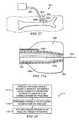
- a reduced pressure delivery systemis provided in accordance with one embodiment of the present invention to apply a reduced pressure to a tissue site.
- the reduced pressure delivery systemincludes a manifold delivery tube having a passageway and a distal end, the distal end configured to be percutaneously inserted and placed adjacent the tissue site.
- a flowable materialis percutaneously deliverable through the manifold delivery tube to the tissue site such that the flowable material is capable of filling a void adjacent the tissue site to create a manifold having a plurality of flow channels in fluid communication with the tissue site.
- a reduced pressure delivery tubeis provided that is capable of fluid communication with the flow channels of the manifold.
- a method of administering a reduced pressure therapy to a tissue siteincludes percutaneously positioning a distal end of a manifold delivery tube adjacent a tissue site.
- a flowable materialis percutaneously delivered through the manifold delivery tube to the tissue site.
- the flowable materialis capable of filling a void adjacent the tissue site to create a manifold having a plurality of flow channels in fluid communication with the tissue site.
- a reduced pressureis applied to the tissue site through the flow channels of the manifold.
- elastomericmeans having the properties of an elastomer.
- the term “elastomer”refers generally to a polymeric material that has rubber-like properties. More specifically, most elastomers have elongation rates greater than 100% and a significant amount of resilience. The resilience of a material refers to the material's ability to recover from an elastic deformation.
- elastomersmay include, but are not limited to, natural rubbers, polyisoprene, styrene butadiene rubber, chloroprene rubber, polybutadiene, nitrile rubber, butyl rubber, ethylene propylene rubber, ethylene propylene diene monomer, chlorosulfonated polyethylene, polysulfide rubber, polyurethane, and silicones.
- the term "flexible”refers to an object or material that is able to be bent or flexed. Elastomeric materials are typically flexible, but reference to flexible materials herein does not necessarily limit material selection to only elastomers.
- the use of the term "flexible” in connection with a material or reduced pressure delivery apparatus of the present inventiongenerally refers to the material's ability to conform to or closely match the shape of a tissue site. For example, the flexible nature of a reduced pressure delivery apparatus used to treat a bone defect may allow the apparatus to be wrapped or folded around the portion of the bone having the defect.
- fluidgenerally refers to a gas or liquid, but may also include any other flowable material, including but not limited to gels, colloids, and foams.
- impermeablegenerally refers to the ability of a membrane, cover, sheet, or other substance to block or slow the transmission of either liquids or gas. Impermeability may be used to refer to covers, sheets, or other membranes that are resistant to the transmission of liquids, while allowing gases to transmit through the membrane. While an impermeable membrane may be liquid tight, the membrane may simply reduce the transmission rate of all or only certain liquids.
- impermeableis not meant to imply that an impermeable membrane is above or below any particular industry standard measurement for impermeability, such as a particular value of water vapor transfer rate (WVTR).
- manifoldgenerally refers to a substance or structure that is provided to assist in applying reduced pressure to, delivering fluids to, or removing fluids from a tissue site.
- a manifoldtypically includes a plurality of flow channels or pathways that are interconnected to improve distribution of fluids provided to and removed from the area of tissue around the manifold.
- manifoldsmay include without limitation devices that have structural elements arranged to form flow channels, cellular foam such as open-cell foam, porous tissue collections, and liquids, gels and foams that include or cure to include flow channels.
- reduced pressuregenerally refers to a pressure less than the ambient pressure at a tissue site that is being subjected to treatment. In most cases, this reduced pressure will be less than the atmospheric pressure at which the patient is located. Alternatively, the reduced pressure may be less than a hydrostatic pressure of tissue at the tissue site. Although the terms “vacuum” and “negative pressure” may be used to describe the pressure applied to the tissue site, the actual pressure applied to the tissue site may be significantly less than the pressure normally associated with a complete vacuum. Reduced pressure may initially generate fluid flow in the tube and the area of the tissue site. As the hydrostatic pressure around the tissue site approaches the desired reduced pressure, the flow may subside, and the reduced pressure is then maintained. Unless otherwise indicated, values of pressure stated herein are gage pressures.
- scaffoldrefers to a substance or structure used to enhance or promote the growth of cells and/or the formation of tissue.
- a scaffoldis typically a three dimensional porous structure that provides a template for cell growth.
- the scaffoldmay be infused with, coated with, or comprised of cells, growth factors, or other nutrients to promote cell growth.
- a scaffoldmay be used as a manifold in accordance with the embodiments described herein to administer reduced pressure tissue treatment to a tissue site.
- tissue siterefers to a wound or defect located on or within any tissue, including but not limited to, bone tissue, adipose tissue, muscle tissue, neural tissue, dermal tissue, vascular tissue, connective tissue, cartilage, tendons, or ligaments.
- tissue sitemay further refer to areas of any tissue that are not necessarily wounded or defective, but are instead areas in which it is desired to add or promote the growth of additional tissue. For example, reduced pressure tissue treatment may be used in certain tissue areas to grow additional tissue that may be harvested and transplanted to another tissue location.
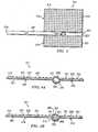
- a reduced pressure delivery apparatus, or wing manifold 211includes a flexible barrier 213 having a spine portion 215 and a pair of wing portions 219. Each wing portion 219 is positioned along opposite sides of the spine portion 215.
- the spine portion 215forms an arcuate channel 223 that may or may not extend the entire length of the wing manifold 211.
- the spine portion 215may be centrally located on the wing manifold 211 such that the width of the wing portions 219 is equal, the spine portion 215 may also be offset as illustrated in FIGS. 1-5 , resulting in one of the wing portions 219 being wider than the other wing portion 219.
- the extra width of one of the wing portions 219may be particularly useful if the wing manifold 211 is being used in connection with bone regeneration or healing and the wider wing manifold 211 is to be wrapped around fixation hardware attached to the bone.
- the flexible barrier 213is preferably formed by an elastomeric material such as a silicone polymer.
- a suitable silicone polymerincludes MED-6015 manufactured by Nusil Technologies of Carpinteria, California. It should be noted, however, that the flexible barrier 213 could be made from any other biocompatible, flexible material.
- the flexible barrier 213encases a flexible backing 227 that adds strength and durability to the flexible barrier 213.
- the thickness of the flexible barrier 213 encasing the flexible backing 227may be less in the arcuate channel 223 than that in the wing portions 219. If a silicone polymer is used to form the flexible barrier 213, a silicone adhesive may also be used to aid bonding with the flexible backing 227.
- the flexible backing 227is preferably made from a polyester knit fabric such as Bard 6013 manufactured by C.R. Bard of Tempe, Arizona. However, the flexible backing 227 could be made from any biocompatible, flexible material that is capable of adding strength and durability to the flexible barrier 213. Under certain circumstances, if the flexible barrier 213 is made from a suitably strong material, the flexible backing 227 could be omitted.
- both the flexible barrier 213 or the flexible backing 227be impermeable to liquids, air, and other gases, or alternatively, both the flexible backing 227 and the flexible barrier 213 may be impermeable to liquids, air, and other gases.
- the flexible barrier 213 and flexible backing 227may also be constructed from bioresorbable materials that do not have to be removed from a patient's body following use of the reduced pressure delivery apparatus 211.
- Suitable bioresorbable materialsmay include, without limitation, a polymeric blend of polylactic acid (PLA) and polyglycolic acid (PGA).
- the polymeric blendmay also include without limitation polycarbonates, polyfumarates, and capralactones.
- the flexible barrier 213 and the flexible backing 227may further serve as a scaffold for new cell-growth, or a scaffold material may be used in conjunction with the flexible barrier 213 and flexible backing 227 to promote cell-growth.
- Suitable scaffold materialmay include, without limitation, calcium phosphate, collagen, PLA/PGA, coral hydroxy apatites, carbonates, or processed allograft materials.
- the scaffold materialwill have a high void-fraction (i.e. a high content of air).
- the flexible backing 227may be adhesively attached to a surface of the flexible barrier 213. If a silicone polymer is used to form the flexible barrier 213, a silicone adhesive may also be used to attach the flexible backing 227 to the flexible barrier 213. While an adhesive is the preferred method of attachment when the flexible backing 227 is surface bonded to the flexible barrier 213, any suitable attachment may be used.
- the flexible barrier 213includes a plurality of projections 231 extending from the wing portions 219 on a surface of the flexible barrier 213.
- the projections 231may be cylindrical, spherical, hemispherical, cubed, or any other shape, as long as at least some portion of each projection 231 is in a plane different than the plane associated with the side of the flexible backing 213 to which the projections 231 are attached.
- a particular projection 231is not even required to have the same shape or size as other projections 231; in fact, the projections 231 may include a random mix of different shapes and sizes. Consequently, the distance by which each projection 231 extends from the flexible barrier 213 could vary, but may also be uniform among the plurality of projections 231.
- projections 231 on the flexible barrier 213creates a plurality of flow channels 233 between the projections.
- the flow channels 233 created between the projections 231are similarly uniform. Variations in the size, shape, and spacing of the projections 231 may be used to alter the size and flow characteristics of the flow channels 233.
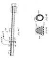
- a reduced-pressure delivery tube 241is positioned within the arcuate channel 223 and is attached to the flexible barrier 213 as illustrated in FIG. 5 .
- the reduced-pressure delivery tube 241may be attached solely to the flexible barrier 213 or the flexible backing 227, or the tube 241 could be attached to both the flexible barrier 213 and the flexible backing 227.
- the reduced-pressure delivery tube 241includes a distal orifice 243 at a distal end of the tube 241.
- the tube 241may be positioned such that the distal orifice 243 is located at any point along the arcuate channel 223, but the tube 241 is preferably positioned such that the distal orifice 243 is located approximately midway along the longitudinal length of the arcuate channel 223.
- the distal orifice 243is preferably made elliptical or oval in shape by cutting the tube 241 along a plane that is oriented less than ninety (90) degrees to the longitudinal axis of the tube 241. While the orifice 243 may also be round, the elliptical shape of the orifice 243 increases fluid communication with the flow channels 233 formed between the projections 231.
- the reduced-pressure delivery tube 241is preferably made from paralyne-coated silicone or urethane. However, any medical-grade tubing material may be used to construct the reduced-pressure delivery tube 241. Other coatings that may coat the tube include heparin, anti-coagulants, anti-fibrinogens, anti-adherents, anti-thrombinogens, and hydrophilic coatings.
- the reduced-pressure delivery tube 241may also include vent openings, or vent orifices 251 positioned along the reduced-pressure delivery tube 241 as either an alternative to the distal orifice 243 or in addition to the distal orifice 243 to further increase fluid communication between the reduced-pressure delivery tube 241 and the flow channels 233.
- the reduced-pressure delivery tube 241may be positioned along only a portion of the longitudinal length of the arcuate channel 223 as shown in FIGS. 1-5 , or alternatively may be positioned along the entire longitudinal length of the arcuate channel 223. If positioned such that the reduced-pressure delivery tube 241 occupies the entire length of the arcuate channel 223, the distal orifice 243 may be capped such that all fluid communication between the tube 241 and the flow channels 233 occurs through the vent openings 251.
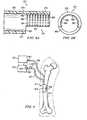
- the reduced-pressure delivery tube 241further includes a proximal orifice 255 at a proximal end of the tube 241.
- the proximal orifice 255is configured to mate with a reduced-pressure source, which is described in more detail below with reference to FIG. 9 .
- the reduced-pressure delivery tube 241 illustrated in FIGS. 1-3 , 4A , and 5includes only a single lumen, or passageway 259. It is possible, however, for the reduced-pressure delivery tube 241 to include multiple lumens such as a dual lumen tube 261 illustrated in FIG. 4B .
- the dual lumen tube 261includes a first lumen 263 and a second lumen 265.
- a dual lumen tubeprovides separate paths of fluid communication between the proximal end of the reduced-pressure delivery tube 241 and the flow channels 233.
- the use of the dual lumen tube 261may be used to allow communication between the reduced pressure source and the flow channels 233 along the first lumen 263.
- the second lumen 265may be used to introduce a fluid to the flow channels 233.
- the fluidmay be filtered air or other gases, antibacterial agents, antiviral agents, cell-growth promotion agents, irrigation fluids, chemically active fluids, or any other fluid. If it is desired to introduce multiple fluids to the flow channels 233 through separate fluid communication paths, a reduced-pressure delivery tube may be provided with more than two lumens.
- a horizontal divider 271separates the first and second lumens 263, 265 of the reduced-pressure delivery tube 261, resulting in the first lumen 263 being positioned above the second lumen 265.
- the relative position of the first and second lumens 263, 265may vary, depending on how fluid communication is provided between the lumens 263, 265 and the flow channels 233. For example, when the first lumen 263 is positioned as illustrated in FIG. 4B , vent openings similar to vent openings 251 may be provided to allow communication with the flow channels 233. When the second lumen 263 is positioned as illustrated in FIG.
- the second lumen 263may communicate with the flow channels 233 through a distal orifice similar to distal orifice 243.
- the multiple lumens of a reduced-pressure delivery tubecould be positioned side by side with a vertical divider separating the lumens, or the lumens could be arranged concentrically or coaxially.
- independent paths of fluid communicationcould be accomplished in a number of different ways, including that of providing a multi-lumen tube as described above.
- independent paths of fluid communicationmay be provided by attaching a single lumen tube to another single lumen tube, or by using separate, unattached tubes with single or multiple lumens.
- the spine portion 215may include multiple arcuate channels 223, one for each tube.
- the arcuate channel 223may be enlarged to accommodate multiple tubes.
- An example of a reduced-pressure delivery apparatus having a reduced-pressure delivery tube separate from a fluid delivery tubeis discussed in more detail below with reference to FIG. 9 .
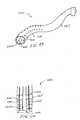
- a reduced pressure delivery apparatus, or wing manifold 311includes a flexible barrier 313 having a spine portion 315 and a pair of wing portions 319. Each wing portion 319 is positioned along opposite sides of the spine portion 315.
- the spine portion 315forms an arcuate channel 323 that may or may not extend the entire length of the wing manifold 311.
- the spine portion 315may be centrally located on the wing manifold 311 such that the size of the wing portions 319 is equal, the spine portion 315 may also be offset as illustrated in FIGS. 6-8 , resulting in one of the wing portions 319 being wider than the other wing portion 319.
- the extra width of one of the wing portions 319may be particularly useful if the wing manifold 311 is being used in connection with bone regeneration or healing and the wider wing manifold 311 is to be wrapped around fixation hardware attached to the bone.
- a cellular material 327is attached to the flexible barrier 313 and may be provided as a single piece of material that covers the entire surface of the flexible barrier 313, extending across the spine portion 315 and both wing portions 319.
- the cellular material 327includes an attachment surface (not visible in FIG. 6 ) that is disposed adjacent to the flexible barrier 313, a main distribution surface 329 opposite the attachment surface, and a plurality of perimeter surfaces 330.
- the flexible barrier 313may be similar to flexible barrier 213 and include a flexible backing. While an adhesive is a preferred method of attaching the cellular material 327 to the flexible barrier 313, the flexible barrier 313 and cellular material 327 could be attached by any other suitable attachment method or left for the user to assemble at the site of treatment.
- the flexible barrier 313 and/or flexible backingserve as an impermeable barrier to transmission of fluids such as liquids, air, and other gases.
- a flexible barrier and flexible backingmay not be separately provided to back the cellular material 327.
- the cellular material 327may have an integral barrier layer that is an impermeable portion of the cellular material 327.
- the barrier layercould be formed from closed-cell material to prevent transmission of fluids, thereby substituting for the flexible barrier 313. If an integral barrier layer is used with the cellular material 327, the barrier layer may include a spine portion and wing portions as described previously with reference to the flexible barrier 313.
- the flexible barrier 313is preferably made from an elastomeric material such as a silicone polymer.
- a suitable silicone polymerincludes MED-6015 manufactured by Nusil Technologies of Carpinteria, California. It should be noted, however, that the flexible barrier 313 could be made from any other biocompatible, flexible material. If the flexible barrier encases or otherwise incorporates a flexible backing, the flexible backing is preferably made from a polyester knit fabric such as Bard 6013 manufactured by C.R. Bard of Tempe, Arizona. However, the flexible backing 227 could be made from any biocompatible, flexible material that is capable of adding strength and durability to the flexible barrier 313.
- the cellular material 327is an open-cell, reticulated polyetherurethane foam with pore sizes ranging from about 400-600 microns.
- An example of this foammay include GranuFoam manufactured by Kinetic Concepts, Inc. of San Antonio, Texas.
- the cellular material 327may also be gauze, felted mats, or any other biocompatible material that provides fluid communication through a plurality of channels in three dimensions.
- the cellular material 327is primarily an "open cell” material that includes a plurality of cells fluidly connected to adjacent cells.
- a plurality of flow channelsis formed by and between the "open cells” of the cellular material 327.
- the flow channelsallow fluid communication throughout that portion of the cellular material 327 having open cells.
- the cells and flow channelsmay be uniform in shape and size, or may include patterned or random variations in shape and size. Variations in shape and size of the cells of the cellular material 327 result in variations in the flow channels, and such characteristics can be used to alter the flow characteristics of fluid through the cellular material 327.
- the cellular material 327may further include portions that include "closed cells.” These closed-cell portions of the cellular material 327 contain a plurality of cells, the majority of which are not fluidly connected to adjacent cells. An example of a closed-cell portion is described above as a barrier layer that may be substituted for the flexible barrier 313. Similarly, closed-cell portions could be selectively disposed in the cellular material 327 to prevent transmission of fluids through the perimeter surfaces 330 of the cellular material 327.
- the flexible barrier 313 and cellular material 327may also be constructed from bioresorbable materials that do not have to be removed from a patient's body following use of the reduced pressure delivery apparatus 311. Suitable bioresorbable materials may include, without limitation, a polymeric blend of polylactic acid (PLA) and polyglycolic acid (PGA). The polymeric blend may also include without limitation polycarbonates, polyfumarates, and capralactones.
- the flexible barrier 313 and the cellular material 327may further serve as a scaffold for new cell-growth, or a scaffold material may be used in conjunction with the flexible barrier 313, flexible backing 327, and/or cellular material 327 to promote cell-growth.
- Suitable scaffold materialsmay include, without limitation, calcium phosphate, collagen, PLA/PGA, coral hydroxy apatites, carbonates, or processed allograft materials.
- the scaffold materialwill have a high void-fraction (i.e. a high content of air).
- a reduced-pressure delivery tube 341is positioned within the arcuate channel 323 and is attached to the flexible barrier 313.
- the reduced-pressure delivery tube 341may also be attached to the cellular material 327, or in the case of only a cellular material 327 being present, the reduced-pressure delivery tube 341 may be attached to only the cellular material 327.
- the reduced-pressure delivery tube 341includes a distal orifice 343 at a distal end of the tube 341 similar to the distal orifice 243 of FIG. 5 .
- the reduced-pressure delivery tube 341may be positioned such that the distal orifice 343 is located at any point along the arcuate channel 323, but is preferably located approximately midway along the longitudinal length of the arcuate channel 323.
- the distal orifice 343is preferably made elliptical or oval in shape by cutting the tube 341 along a plane that is oriented less than ninety (90) degrees to the longitudinal axis of the tube 341. While the orifice may also be round, the elliptical shape of the orifice increases fluid communication with the flow channels in the cellular material 327.
- the reduced-pressure delivery tube 341may also include vent openings, or vent orifices (not shown) similar to vent openings 251 of FIG. 5 .
- the vent openingsare positioned along the tube 341 as either an alternative to the distal orifice 343 or in addition to the distal orifice 343 to further increase fluid communication between the reduced-pressure delivery tube 341 and the flow channels.
- the reduced-pressure delivery tube 341may be positioned along only a portion of the longitudinal length of the arcuate channel 323, or alternatively may be positioned along the entire longitudinal length of the arcuate channel 323. If positioned such that the reduced-pressure delivery tube 341 occupies the entire arcuate channel 323, the distal orifice 343 may be capped such that all fluid communication between the tube 341 and the flow channels occurs through the vent openings.
- the cellular material 327overlays and directly contacts the reduced-pressure delivery tube 341.
- the cellular material 327may be connected to the reduced-pressure delivery tube 341, or the cellular material 327 may simply be attached to the flexible barrier 313. If the reduced-pressure delivery tube 341 is positioned such that it only extends to a midpoint of the arcuate channel 323, the cellular material 327 may also be connected to the spine portion 315 of the flexible barrier 313 in that area of the arcuate channel 323 that does not contain the reduced-pressure delivery tube 341.
- the reduced-pressure delivery tube 341further includes a proximal orifice 355 at a proximal end of the tube 341.
- the proximal orifice 355is configured to mate with a reduced-pressure source, which is described in more detail below with reference to FIG. 9 .
- the reduced-pressure delivery tube 341 illustrated in FIGS. 6-8includes only a single lumen, or passageway 359. It is possible, however, for the reduced-pressure delivery tube 341 to include multiple lumens such as those described previously with reference to FIG. 4B .
- the use of a multiple lumen tubeprovides separate paths of fluid communication between the proximal end of the reduced-pressure delivery tube 341 and the flow channels as previously described. These separate paths of fluid communication may also be provided by separate tubes having single or multiple lumens that communicate with the flow channels.
- a reduced pressure delivery apparatus 371includes a reduced pressure delivery tube 373 having an extension portion 375 at a distal end 377 of the reduced pressure delivery tube 373.
- the extension portion 375is preferably arcuately shaped to match the curvature of the reduced pressure delivery tube 373.
- the extension portion 375may be formed by removing a portion of the reduced pressure delivery tube 373 at the distal end 377, thereby forming a cut-out 381 having a shoulder 383.
- a plurality of projections 385is disposed on an inner surface 387 of the reduced pressure delivery tube 373 to form a plurality of flow channels 391 between the projections 385.
- the projections 385may be similar in size, shape, and spacing as the projections described with reference to FIGS. 1-5 .
- the reduced pressure delivery apparatus 371is particularly suited for applying reduced pressure to and regenerating tissue on connective tissues that are capable of being received within the cut-out 381.
- Ligaments, tendons, and cartilageare non-limiting examples of the tissues that may be treated by reduced pressure delivery apparatus 371.
- a reduced pressure delivery apparatus 411similar to the other reduced pressure delivery apparatuses described herein is used to apply a reduced pressure tissue treatment to a tissue site 413, such as a human bone 415 of a patient.
- reduced pressure tissue treatmentcan increase the rate of healing associated with a fracture, a non-union, a void, or other bone defects. It is further believed that reduced pressure tissue treatment may be used to improve recovery from osteomyelitis. The therapy may further be used to increase localized bone densities in patients suffering from osteoporosis.
- reduced pressure tissue treatmentmay be used to speed and improve oseointegration of orthopedic implants such as hip implants, knee implants, and fixation devices.
- the reduced pressure delivery apparatus 411includes a reduced-pressure delivery tube 419 having a proximal end 421 fluidly connected to a reduced pressure source 427.
- the reduced pressure source 427is a pump or any other device that is capable of applying a reduced pressure to the tissue site 413 through the reduced pressure delivery tube 419 and a plurality of flow channels associated with the reduced pressure delivery apparatus 411. Applying reduced pressure to the tissue site 413 is accomplished by placing the wing portions of the reduced pressure delivery apparatus 411 adjacent the tissue site 413, which in this particular example involves wrapping the wing portions around a void defect 429 in the bone 415.
- the reduced pressure delivery apparatus 411may be surgically or percutaneously inserted. When percutaneously inserted, the reduced-pressure delivery tube 419 is preferably inserted through a sterile insertion sheath that penetrates the skin tissue of the patient.
- Granulation tissueis a common tissue that often forms prior to tissue repair in the body. Under normal circumstances, granulation tissue may form in response to a foreign body or during wound healing. Granulation tissue typically serves as a scaffold for healthy replacement tissue and further results in the development of some scar tissue. Granulation tissue is highly vascularized, and the increased growth and growth rate of the highly vascularized tissue in the presence of reduced pressure promotes new tissue growth at the tissue site 413.
- a fluid delivery tube 431may be fluidly connected at a distal end to the flow channels of the reduced pressure delivery apparatus 411.
- the fluid delivery tube 431includes a proximal end 432 that is fluidly connected to a fluid delivery source 433.
- the airis preferably filtered by a filter 434 capable of filtering particles at least as small as 0.22 ⁇ m in order to clean and sterilize the air.
- the introduction of air to the tissue site 413, especially when the tissue site 413 is located beneath the surface of the skin,is important to facilitate good drainage of the tissue site 413, thereby reducing or preventing obstruction of the reduced pressure delivery tube 419.
- the fluid delivery tube 431 and fluid delivery source 433could also be used to introduce other fluids to the tissue site 413, including without limitation an antibacterial agent, an antiviral agent, a cell-growth promotion agent, an irrigation fluid, or other chemically active agents.
- the fluid delivery tube 431is preferably inserted through a sterile insertion sheath that penetrates the skin tissue of the patient.
- a pressure sensor 435may be operably connected to the fluid delivery tube 431 to indicate whether the fluid delivery tube 431 is occluded with blood or other bodily fluids.
- the pressure sensor 435may be operably connected to the fluid delivery source 433 to provide feedback so that the amount of fluid introduced to the tissue site 413 is controlled.
- a check valve(not shown) may also be operably connected near the distal end of the fluid delivery tube 431 to prevent blood or other bodily fluids from entering the fluid delivery tube 431.
- the independent paths of fluid communication provided by reduced pressure delivery tube 419 and fluid delivery tube 431may be accomplished in a number of different ways, including that of providing a single, multi-lumen tube as described previously with reference to FIG 4B .
- a person of ordinary skill in the artwill recognize that the sensors, valves, and other components associated with the fluid delivery tube 431 could also be similarly associated with a particular lumen in the reduced pressure delivery tube 419 if a multi-lumen tube is used.
- any lumen or tube that fluidly communicates with the tissue sitebe coated with an anti-coagulent to prevent a build-up of bodily fluids or blood within the lumen or tube.
- Other coatings that may coat the lumens or tubesinclude without limitation heparin, anti-coagulants, anti-fibrinogens, anti-adherents, anti-thrombinogens, and hydrophilic coatings.
- testinghas shown the positive effects of reduced pressure tissue treatment when applied to bone tissue.
- reduced pressure tissue treatmentwas applied to the cranium of several rabbits to determine its effect on bone growth and regeneration.
- the specific goals of the testwere to discover the effect of reduced pressure tissue treatment on rabbits having no defect on or injury to the cranium, the effect of reduced pressure tissue treatment on rabbits having critical-size defects on the cranium, and the effect of using a scaffold material with reduced pressure tissue treatment to treat critical-size defects on the cranium.
- the specific testing protocol and number of rabbitsare listed below in Table 1. Table 1: Testing Protocol No.
- Critical-size defectsare defects in a tissue (e.g. the cranium), the size of which is large enough that the defect will not heal solely by in-life recovery. For rabbits, boring a full-thickness hole through the cranium that is approximately 15 mm in diameter creates a critical-size defect of the cranium.
- FIG. 10a histological section of a rabbit cranium having na ⁇ ve, undamaged bone is illustrated.
- the bone tissue of the craniumis colored magenta, the surrounding soft tissue white, and the layer of periosteum is highlighted by yellow asterisks.
- FIG. 11the rabbit cranium is illustrated following the application of reduced pressure tissue treatment for 6 days followed by immediate tissue harvest. The bone and periosteum are visible, and a layer of granulation tissue has developed.
- FIG. 12the rabbit cranium is illustrated following the application of reduced pressure tissue treatment for 6 days and followed by immediate tissue harvest.
- the histological section of FIG. 12is characterized by the development of new bone tissue underlying the granulation tissue.
- the bone tissueis highlighted by yellow asterisks.
- the rabbit craniumis illustrated following the application of reduced pressure tissue treatment for 6 days followed by immediate tissue harvest. The new bone and periosteum are visible. This histological appearance of bone tissue development in response to reduced pressure tissue treatment is very similar to the histological appearance of bone development in a very young animal that is undergoing very rapid growth and deposition of new bone.
- FIGS. 14-19several photographs and histological sections are illustrated showing the procedures and results of reduced pressure tissue treatment on a rabbit cranium having critical-size defects.
- a rabbit craniumis illustrated on which two critical-size defects have been created. The full-thickness critical-size defects are approximately 15 mm in diameter.
- a stainless-steel screenhas been placed over one of the critical-size defects, and a calcium phosphate scaffold has been placed within the second critical-size defect.
- a reduced pressure tissue treatment apparatus similar to those described hereinis used to apply reduced pressure to the critical-size defects. The amount of pressure applied to each defect was -125 mm Hg gauge pressure.
- the reduced pressurewas applied according to one of the protocols listed in Table 1.
- FIG. 17a histological section of cranium following six-day reduced pressure tissue treatment and twelve week post-surgery harvest is illustrated.
- the section illustratedincludes calcium phosphate scaffold, which is indicated by red arrows.
- the application of reduced pressure tissue treatmentresulted in the significant growth of new bone tissue, which is highlighted in FIG. 17 by yellow asterisks.
- the amount of bone growthis significantly greater than in critical-size defects containing identical calcium phosphate scaffolds but which were not treated with reduced pressure tissue treatment. This observation suggests there may be a threshold level or duration of therapy required to elicit a prolific new-bone response. Effects of reduced pressure tissue treatment are most pronounced in the specimens collected 12 weeks post-surgery, indicating the reduced pressure tissue treatment initiates a cascade of biological events leading to enhanced formation of new bone tissue.
- FIGS. 18 and 19radiographs of scaffold-filled, critical-size defects are illustrated following six days of reduced pressure tissue treatment.
- FIG. 18illustrates the defect two weeks post-surgery and indicates some new bone deposition within the scaffold. The primary structure of the scaffold is still evident.
- FIG. 19illustrates the defect twelve weeks post surgery and shows almost complete healing of the critical-size defect and a near complete loss of the primary scaffold architecture due to tissue integration, i.e. new bone formation within the scaffold matrix.
- a reduced pressure delivery system 711delivers reduced pressure tissue treatment to a tissue site 713 of a patient.
- the reduced pressure delivery system 711includes a manifold delivery tube 721.
- the manifold delivery tube 721may be a catheter or cannula and may include features such as a steering unit 725 and a guide wire 727 that allow the manifold delivery tube 721 to be guided to the tissue site 713. Placement and direction of the guide wire 727 and the manifold delivery tube 721 may be accomplished by using endoscopy, ultrasound, fluoroscopy, auscultation, palpation, or any other suitable localization technique.
- the manifold delivery tube 721is provided to percutaneously insert a reduced pressure delivery apparatus to the tissue site 713 of the patient.
- the manifold delivery tube 721is preferably inserted through a sterile insertion sheath that penetrates the skin tissue of the patient.
- the tissue site 713includes bone tissue adjacent a fracture 731 on a bone 733 of the patient.
- the manifold delivery tube 721is inserted through the patient's skin 735 and any soft tissue 739 surrounding the bone 733.
- the tissue site 713may also include any other type of tissue, including without limitation adipose tissue, muscle tissue, neural tissue, dermal tissue, vascular tissue, connective tissue, cartilage, tendons, or ligaments.
- the manifold delivery tube 721may include a tapered distal end 743 to ease insertion through the patient's skin 735 and soft tissue 739.
- the tapered distal end 743may further be configured to flex radially outward to an open position such that the inner diameter of the distal end 743 would be substantially the same as or greater than the inner diameter at other portions of the tube 721.
- the open position of the distal end 743is schematically illustrated in FIG. 21 by broken lines 737.
- the manifold delivery tube 721further includes a passageway 751 in which a reduced pressure delivery apparatus 761, or any other reduced pressure delivery apparatus, is contained.
- the reduced pressure delivery apparatus 761includes a flexible barrier 765 and/or cellular material 767 similar to that described with reference to FIGS. 6-8 .
- the flexible barrier 765 and/or cellular material 767is preferably rolled, folded, or otherwise compressed around a reduced pressure delivery tube 769 to reduce the cross-sectional area of the reduced pressure delivery apparatus 761 within the passageway 751.
- the reduced pressure delivery apparatus 761may be placed within the passageway 751 and guided to the tissue site 713 following the placement of the distal end 743 manifold delivery tube 721 at the tissue site 713. Alternatively, the reduced pressure delivery apparatus 761 may be pre-positioned within the passageway 751 prior to the manifold delivery tube 721 being inserted into the patient. If the reduced pressure delivery apparatus 761 is to be pushed through the passageway 751, a biocompatible lubricant may be used to reduce friction between the reduced pressure delivery apparatus 761 and the manifold delivery tube 721.
- the reduced pressure delivery apparatus 761When the distal end 743 has been positioned at the tissue site 713 and the reduced pressure delivery apparatus 761 has been delivered to the distal end 743, the reduced pressure delivery apparatus 761 is then pushed toward the distal end 743, causing the distal end 743 to expand radially outward into the open position.
- the reduced pressure delivery apparatus 761is pushed out of the manifold delivery tube 721, preferably into a void or space adjacent the tissue site 713.
- the void or spaceis typically formed by dissection of soft tissue, which may be accomplished by percutaneous means.
- the tissue site 713may be located at a wound site, and a void may be naturally present due to the anatomy of the wound.
- the voidmay be created by balloon dissection, sharp dissection, blunt dissection, hydrodissection, pneumatic dissection, ultrasonic dissection, electrocautery dissection, laser dissection, or any other suitable dissection technique.
- the flexible barrier 765 and/or cellular material 767 of the reduced pressure delivery apparatus 761either unrolls, unfolds, or decompresses (see FIG. 22 ) such that the reduced pressure delivery apparatus 761 can be placed in contact with the tissue site 713.
- the flexible barrier 765 and/or cellular material 767may be subjected to a vacuum or reduced pressure supplied through the reduced pressure delivery tube 769 to compress the flexible barrier 765 and/or cellular material 767.
- the unfolding of the flexible barrier 765 and/or cellular material 767may be accomplished by either relaxing the reduced pressure supplied through the reduced pressure delivery tube 769 or by supplying a positive pressure through the reduced pressure delivery tube 769 to assist the unrolling process.
- Final placement and manipulation of the reduced pressure delivery apparatus 761may be accomplished by using endoscopy, ultrasound, fluoroscopy, auscultation, palpation, or any other suitable localization technique.
- the manifold delivery tube 721is preferably removed from the patient, but the reduced pressure delivery tube associated with reduced pressure delivery apparatus 761 remains in situ to allow percutaneous application of reduced pressure to the tissue site 713.
- a reduced pressure delivery system 811includes a manifold delivery tube 821 having a tapered distal end 843 that is configured to flex radially outward to an open position such that the inner diameter of the distal end 843 would be substantially the same as or greater than the inner diameter at other portions of the tube 821.
- the open position of the distal end 843is schematically illustrated in FIGS. 23-25 by broken lines 837.
- the manifold delivery tube 821further includes a passageway in which a reduced pressure delivery apparatus 861 similar to the other reduced pressure delivery apparatuses described herein is contained.
- the reduced pressure delivery apparatus 861includes a flexible barrier 865 and/or a cellular material 867 that is preferably rolled, folded, or otherwise compressed around a reduced pressure delivery tube 869 to reduce the cross-sectional area of the reduced pressure delivery apparatus 861 within the passageway.
- An impermeable membrane 871 having an inner space 873is disposed around the reduced pressure delivery apparatus 861 such that the reduced pressure delivery apparatus 861 is contained within the inner space 873 of the impermeable membrane 871.
- the impermeable membrane 871may be a balloon, a sheath, or any other type of membrane that is capable of preventing fluid transmission such that the impermeable membrane 871 can assume at least one of a compressed position (see FIG. 23 ), a relaxed position (see FIG. 24 ), and an expanded position (see FIGS. 25 and 25A ).
- the impermeable membrane 871may be sealingly connected to the manifold delivery tube 821 such that the inner space 873 of the impermeable membrane 871 is in fluid communication with the passageway of the manifold delivery tube 821.
- the impermeable membrane 871may alternatively be attached to the reduced pressure delivery tube 869 such that the inner space 873 of the impermeable membrane 871 is in fluid communication with the passageway of the reduced pressure delivery tube 869.
- the impermeable membrane 871instead may be attached to a separate control tube or control lumen (see for example FIG. 25A ) that fluidly communicates with the inner space 873.
- the impermeable membrane 871may be provided to further reduce the cross-sectional area of the reduced pressure delivery apparatus 861 within the passageway. To accomplish this, a pressure is applied to the inner space 873 of the impermeable membrane 871 that is less than the ambient pressure surrounding the impermeable membrane 871. A significant portion of the air or other fluid within the inner space 873 is thereby evacuated, placing the impermeable membrane 871 in the compressed position illustrated in FIG. 23 . In the compressed position, the impermeable membrane 871 is drawn inward such that a compressive force is applied to the reduced pressure delivery apparatus 861 to further reduce the cross-sectional area of the reduced pressure delivery apparatus 861. As previously described with reference to FIGS.
- the reduced pressure delivery apparatus 861may be delivered to the tissue site following the placement of the distal end 843 of the manifold delivery tube 821 at the tissue site. Placement and manipulation of the impermeable membrane 871 and the reduced pressure delivery apparatus 861 may be accomplished by using endoscopy, ultrasound, fluoroscopy, auscultation, palpation, or any other suitable localization technique.
- the impermeable membrane 871may include radio-opaque markers 881 that improve visualization of the impermeable membrane 871 under fluoroscopy prior to its removal.
- the reduced pressure applied to the inner space 873may be eased to place the impermeable membrane 871 in the relaxed position (see FIG. 24 ), thereby facilitating easier removal of the reduced pressure delivery apparatus 861 from the impermeable membrane 871.
- a removal instrument 885such as a trocar, stylet, or other sharp instrument may be provided to rupture the impermeable membrane 871.
- the removal instrument 885is inserted through the reduced pressure delivery tube 869 and is capable of being advanced into contact with the impermeable membrane 871.
- the removal instrument 885 and the impermeable membrane 871may be withdrawn through the manifold delivery tube 821, allowing the flexible barrier 865 and/or cellular material 867 of the reduced pressure delivery apparatus 861 to unroll, unfold, or decompress such that the reduced pressure delivery apparatus 861 can be placed in contact with the tissue site.
- the unrolling of the flexible barrier 865 and/or cellular material 867may occur automatically following the relaxation of reduced pressure to the inner space 873 and the removal of the impermeable membrane 871.
- a positive pressuremay be delivered through the reduced pressure delivery tube 869 to assist in unrolling or decompressing the flexible barrier 865 and/or cellular material 867.
- the manifold delivery tube 821is preferably removed from the patient, but the reduced pressure delivery tube 869 associated with the reduced pressure delivery apparatus 861 remains in situ to allow percutaneous application of reduced pressure to the tissue site.
- the impermeable membrane 871may also be used to dissect tissue adjacent the tissue site prior to placing the reduced pressure delivery apparatus 861 against the tissue site. After pushing the reduced pressure delivery apparatus 861 and intact impermeable membrane 871 through the distal end 843 of the manifold delivery tube 821, air or another fluid may be injected or pumped into the inner space 873 of the impermeable membrane 871.
- a liquidis preferably used to inflate the impermeable membrane 871 since the incompressibility of liquids allow the impermeable membrane 871 to expand more evenly and consistently.
- the impermeable membrane 871may expand radially as illustrated in FIG. 25 or directionally depending on its method of manufacture and attachment to the manifold delivery tube 821.
- the impermeable membrane 871As the impermeable membrane 871 expands outward into the expanded position (see FIG. 25 ) due to the pressure of the air or fluid, a void is dissected adjacent the tissue site. When the void is large enough, the liquid, air or other fluid may be released from the inner space 873 to allow the impermeable membrane 871 to assume the relaxed position. The impermeable membrane 871 may then be ruptured as previously explained and the reduced pressure delivery apparatus 861 inserted adjacent the tissue site.
- the impermeable membrane 871may be sealingly attached to the manifold delivery tube 821 such that the inner space 873 fluidly communicates with a secondary lumen or tube 891 associated with or attached to the manifold delivery tube 821.
- the secondary lumen 891may be used to deliver a liquid, air, or other fluid to the inner space 873 to place the impermeable membrane 871 in the expanded position.
- the impermeable membrane 871may be relaxed and ruptured as previously described with reference to FIG. 24 .
- a reduced pressure delivery system 911includes a manifold delivery tube 921 having a tapered distal end 943 that is configured to flex radially outward to an open position such that the inner diameter of the distal end 943 would be substantially the same as or greater than the inner diameter at other portions of the tube 921.
- the open position of the distal end 943is schematically illustrated in FIG. 26 by broken lines 937.
- the manifold delivery tube 921further includes a passageway in which a reduced pressure delivery apparatus 961 similar to the other reduced pressure delivery apparatuses described herein is contained.
- the reduced pressure delivery apparatus 961includes a flexible barrier 965 and/or a cellular material 967 that is preferably rolled, folded, or otherwise compressed around a reduced pressure delivery tube 969 to reduce the cross-sectional area of the reduced pressure delivery apparatus 961 within the passageway of the manifold delivery tube 921.
- An impermeable membrane 971 having an inner space 973is disposed around the reduced pressure delivery apparatus 961 such that the reduced pressure delivery apparatus 961 is contained within the inner space 973 of the impermeable membrane 971.
- the impermeable membrane 971includes a glue seal 977 on one end of the impermeable membrane 971 to provide an alternative method of removing the reduced pressure delivery apparatus 961 from the impermeable membrane 971.
- the impermeable membrane 971may be sealingly connected at another end to the manifold delivery tube 921 such that the inner space 973 of the impermeable membrane 971 is in fluid communication with the passageway of the manifold delivery tube 921.
- the impermeable membrane 971may be attached to a separate control tube (not shown) that fluidly communicates with the inner space 973.
- impermeable membrane 971may be capable of preventing fluid transmission such that the impermeable membrane 971 can assume at least one of a compressed position, a relaxed position, and an expanded position. Since the procedures for placing the impermeable membrane 971 in a compressed position and an expanded position are similar to those for impermeable membrane 871, only the differing process of removing the reduced pressure delivery apparatus 961 is described.
- the reduced pressure delivery apparatus 961is delivered to the tissue site within the impermeable membrane 971 and then properly positioned using endoscopy, ultrasound, fluoroscopy, auscultation, palpation, or any other suitable localization technique.
- the impermeable membrane 971may include radio-opaque markers 981 that improve visualization of the impermeable membrane 971 under fluoroscopy prior to its removal.
- the reduced pressure delivery apparatus 961is then pushed through the distal end 943 of the manifold delivery tube 921.
- the reduced pressure applied to the inner space 973may be eased to place the impermeable membrane 971 in the relaxed position.
- the reduced pressure delivery apparatus 961is then pushed through the glue seal 977 to exit the impermeable membrane 971.
- a reduced pressure delivery system 985may not include a manifold delivery tube similar to manifold delivery tube 921 of FIG. 26 .
- the reduced pressure delivery system 985may include a guide wire 987, a reduced pressure delivery tube 989, and a reduced pressure delivery apparatus 991.
- the reduced pressure delivery apparatus 991includes a plurality flow channels that is fluidly connected to the reduced pressure delivery tube 989.
- the reduced pressure delivery apparatus 991 and reduced pressure delivery tube 989are placed on the guide wire 987, which is percutaneously guided to a tissue site 993.
- the guide wire 987 and reduced pressure delivery tube 989penetrate the skin of the patient through a sterile sheath.
- the reduced pressure delivery apparatus 991may be placed at the tissue site 993 to allow percutaneous application of reduced pressure tissue treatment.
- the reduced pressure delivery apparatus 991is not constrained within a manifold delivery tube during delivery to the tissue site 993, it is preferable to hold the reduced pressure delivery apparatus 991 in a compressed position during delivery.
- an elastic foamis used as the reduced pressure delivery apparatus 991
- a biocompatible, soluble adhesivemay be applied to the foam and the foam compressed.
- bodily fluids or other fluids delivered through the reduced pressure delivery tube 989dissolve the adhesive, allowing the foam to expand into contact with the tissue site.
- the reduced pressure delivery apparatus 991may be formed from a compressed, dry hydrogel. The hydrogel absorbs moisture following delivery to the tissue site 993 allowing expansion of the reduced pressure delivery apparatus 991.
- Still another reduced pressure delivery apparatus 991may be made from a thermoactive material (e.g. polyethylene glycol) that expands at the tissue site 993 when exposed to the body heat of the patient.
- a compressed reduced pressure delivery apparatus 991may be delivered to the tissue site 993 in a dissolvable membrane.
- a reduced pressure delivery system 1011includes a manifold delivery tube 1021 having a distal end 1043 that is inserted through a tissue of a patient to access a tissue site 1025.
- the tissue site 1025may include a void 1029 that is associated with a wound or other defect, or alternatively a void may be created by dissection, including the dissection techniques described herein.
- an injectable, pourable, or flowable reduced pressure delivery apparatus 1035is delivered through the manifold delivery tube 1021 to the tissue site 1025.
- the reduced pressure delivery apparatus 1035preferably exists in a flowable state during delivery to the tissue site, and then, after arrival forms a plurality of flow channels for distribution of reduced pressure or fluids.
- the flowable materialmay harden into a solid state after arrival at the tissue site, either through a drying process, a curing process, or other chemical or physical reaction. In other cases, the flowable material may form a foam in-situ following delivery to the tissue site.
- the amount of reduced pressure delivery apparatus 1035 delivered to the tissue site 1025may be enough to partially or completely fill the void 1029.
- the reduced pressure delivery apparatus 1035may include aspects of both a manifold and a scaffold.
- the reduced pressure delivery apparatus 1035includes a plurality of pores or open cells that may be formed in the material after delivery to the void 1029. The pores or open cells communicate with one another, thereby creating a plurality of flow channels. The flow channels are used to apply and distribute reduced pressure to the tissue site 1025.
- the reduced pressure delivery apparatus 1035is bioresorbable and serves as a substrate upon and within which new tissue may grow.
- the reduced pressure delivery apparatus 1035may include poragens such as NaCl or other salts that are distributed throughout a liquid or viscous gel. After the liquid or viscous gel is delivered to the tissue site 1025, the material conforms to the void 1029 and then cures into a solid mass. The water-soluble NaCl poragens dissolve in the presence of bodily fluids leaving a structure with interconnected pores, or flow channels. Reduced pressure and/or fluid is delivered to the flow channels. As new tissue develops, the tissue grows into the pores of the reduced pressure delivery apparatus 1035, and then ultimately replaces the reduced pressure delivery apparatus 1035 as it degrades. In this particular example, the reduced pressure delivery apparatus 1035 serves not only as a manifold, but also as a scaffold for new tissue growth.
- poragenssuch as NaCl or other salts that are distributed throughout a liquid or viscous gel. After the liquid or viscous gel is delivered to the tissue site 1025, the material conforms to the void 1029 and then cures into a solid
- the reduced pressure delivery apparatus 1035is an alginate mixed with 400 ⁇ m mannose beads.
- the poragens or beadsmay be dissolved by local body fluids or by irrigational or other fluids delivered to the reduced pressure delivery apparatus 1035 at the tissue site. Following dissolution of the poragens or beads, the spaces previously occupied by the poragens or beads become voids that are interconnected with other voids to form the flow channels within the reduced pressure delivery apparatus 1035.
- poragensto create flow channels in a material are effective, but it also forms pores and flow channels that are limited in size to approximately the particle size of the selected poragen.
- a chemical reactionmay be used to create larger pores due to the formation of gaseous by-products.
- a flowable materialmay be delivered to the tissue site 1025 that contains sodium bicarbonate and citric acid particles (non-stoichiometric amounts may be used). As the flowable material forms a foam or solid in-situ, bodily fluids will initiate an acid-base reaction between the sodium bicarbonate and the citric acid. The resulting carbon dioxide gas particles that are produced create larger pore and flow channels throughout the reduced pressure delivery apparatus 1035 than techniques relying on poragen dissolution.
- the transformation of the reduced pressure delivery apparatus 1035 from a liquid or viscous gel into a solid or a foamcan be triggered by pH, temperature, light, or a reaction with bodily fluids, chemicals or other substances delivered to the tissue site. The transformation may also occur by mixing multiple reactive components.
- the reduced pressure delivery apparatus 1035is prepared by selecting bioresorbable microspheres made from any bioresorbable polymer. The microspheres are dispersed in a solution containing a photoinitiator and a hydrogel-forming material such as hyaluronic acid, collagen, or polyethylene glycol with photoreactive groups. The microsphere-gel mixture is exposed to light for a brief period of time to partially crosslink the hydrogel and immobilize the hydrogel on the microspheres.
- the excess solutionis drained, and the microspheres are then dried.
- the microspheresare delivered to the tissue site by injection or pouring, and following delivery, the mixture absorbs moisture, and the hydrogel coating becomes hydrated.
- the mixtureis then again exposed to light, which crosslinks the microspheres, creating a plurality of flow channels.
- the crosslinked microspheresthen serve as a manifold to deliver reduced pressure to the tissue site and as a porous scaffold to promote new tissue growth.
- the reduced pressure delivery apparatus 1035may be made from a variety of materials, including without limitation calcium phosphate, collagen, alginate, cellulose, or any other equivalent material that is capable of being delivered to the tissue site as a gas, liquid, gel, paste, putty, slurry, suspension, or other flowable material and is capable of forming multiple flow paths in fluid communication with the tissue site.
- the flowable materialmay further include particulate solids, such as beads, that are capable of flowing through the manifold delivery tube 1021 if the particulate solids are sufficiently small in size. Materials that are delivered to the tissue site in a flowable state may polymerize or gel in-situ.
- the reduced pressure delivery apparatus 1035may injected or poured directly into the void 1029 adjacent the tissue site 1025.
- the manifold delivery tube 1021may include an impermeable or semi-permeable membrane 1051 at the distal end 1043 of the manifold delivery tube 1021.
- the membrane 1051includes an inner space 1055 that fluidly communicates with a secondary lumen 1057 attached to the manifold delivery tube 1021.
- the manifold delivery tube 1021is guided to the tissue site 1025 over a guide wire 1061.
- the reduced pressure delivery apparatus 1035may be injected or poured through the secondary lumen 1057 to fill the inner space 1055 of the membrane 1051.
- the membrane 1051expands to fill the void 1029 such that the membrane is in contact with the tissue site 1025.
- the membrane 1051may be used to dissect additional tissue adjacent or near the tissue site 1025.
- the membrane 1051if impermeable, may be physically ruptured and removed, leaving behind the reduced pressure delivery apparatus 1035 in contact with the tissue site 1025.
- the membrane 1051may be made from a dissolvable material that dissolves in the presence of bodily fluids or biocompatible solvents that may be delivered to the membrane 1051. If the membrane 1051 is semi-permeable, the membrane 1051 may remain in situ. The semi-permeable membrane 1051 allows communication of reduced pressure and possibly other fluids to the tissue site 1025.
- a method 1111 of administering a reduced pressure tissue treatment to a tissue siteincludes at 1115 surgically inserting a manifold adjacent the tissue site, the manifold having a plurality of projections extending from a flexible barrier to create a plurality of flow channels between the projections.
- the manifoldis positioned at 1119 such that at least a portion of the projections are in contact with the tissue site.
- a reduced pressureis applied through the manifold to the tissue site.
- a method 1211 of administering a reduced pressure tissue treatment to a tissue siteincludes at 1215 percutaneously inserting a manifold adjacent the tissue site.
- the manifoldmay include a plurality of projections extending from a flexible barrier to create a plurality of flow channels between the projections.
- the manifoldmay include cellular material having a plurality of flow channels within the cellular material.
- the manifoldmay be formed from an injectable or pourable material that is delivered to the tissue site and forms a plurality of flow channels after arriving at the tissue site.
- the manifoldis positioned such that at a least a portion of the flow channels are in fluid communication with the tissue site.
- a reduced pressureis applied to the tissue site through the manifold at 1223.
- a method 1311 of administering a reduced pressure tissue treatment to a tissue siteincludes at 1315 percutaneously inserting a tube having a passageway through a tissue of a patient to place a distal end of the tube adjacent the tissue site.
- a balloon associated with the tubemay be inflated to dissect tissue adjacent the tissue site, thereby creating a void.
- a manifoldis delivered through the passageway.
- the manifoldmay include a plurality of projections extending from a flexible barrier to create a plurality of flow channels between the projections.
- the manifoldmay include cellular material having a plurality of flow channels within the cellular material.
- the manifoldmay be formed from an injectable or pourable material that is delivered to the tissue site as described previously with reference to FIG. 27 .
- the manifoldis positioned in the void at 1327 such that at least a portion of the flow channels are in fluid communication with the tissue site.
- a reduced pressureis applied to the tissue site through the manifold via a reduced pressure delivery tube or any other delivery means.
- a method 1411 of administering a reduced pressure tissue treatment to a tissue siteincludes at 1415 percutaneously inserting a tube having a passageway through a tissue of a patient to place a distal end of the tube adjacent the tissue site.
- a manifoldis delivered through the passageway to the tissue site within an impermeable sheath, the impermeable sheath at 1419 having been subjected to a first reduced pressure less than an ambient pressure of the sheath.
- the sheathis ruptured to place the manifold in contact with the tissue site.
- a second reduced pressureis applied through the manifold to the tissue site.
- a reduced pressure delivery apparatus 1511includes an orthopedic hip prosthesis 1515 for replacing the existing femoral head of a femur 1517 of a patient.
- the hip prosthesis 1515includes a stem portion 1521 and a head portion 1525.
- the stem portion 1521is elongated for insertion within a passage 1529 reamed in a shaft of the femur 1517.
- a porous coating 1535is disposed around the stem portion and preferably is constructed from sintered or vitrified ceramics or metal. Alternatively, a cellular material having porous characteristic could be disposed around the stem portion.
- a plurality of flow channels 1541is disposed within the stem portion 1521 of the hip prosthesis 1515 such that the flow channels 1541 are in fluid communication with the porous coating 1535.
- a connection port 1545is fluidly connected to the flow channels 1541, the port being configured for releasable connection to a reduced pressure delivery tube 1551 and a reduced pressure delivery source 1553.
- the flow channels 1541are used to deliver a reduced pressure to the porous coating 1535 and/or the bone surrounding the hip prosthesis 1515 following implantation.
- the flow channels 1541may include a main feeder line 1543 that fluidly communicates with several lateral branch lines 1547, which communicate with the porous coating 1535.
- the lateral branch lines 1545may be oriented normal to the main feeder line 1543 as illustrated in FIG.
- An alternative method for distributing the reduced pressureincludes providing a hollow hip prosthesis, and filling the inner space of the prosthesis with a cellular (preferably open-cell) material that is capable of fluidly communicating with the porous coating 1535.
- hip prosthesis 1515may further include a second plurality of flow channels 1561 within the stem portion 1521 to provide a fluid to the porous coating 1535 and/or the bone surrounding the hip prosthesis 1515.
- the fluidcould include filtered air or other gases, antibacterial agents, antiviral agents, cell-growth promotion agents, irrigation fluids, chemically active fluids, or any other fluid. If it is desired to introduce multiple fluids to the bone surrounding the hip prosthesis 1515, additional paths of fluid communication may be provided.
- a connection port 1565is fluidly connected to the flow channels 1561, the port 1565 being configured for releasable connection to a fluid delivery tube 1571 and a fluid delivery source 1573.
- the flow channels 1561may include a main feeder line 1583 that fluidly communicates with several lateral branch lines 1585, which communicate with the porous coating 1535.
- the lateral branch lines 1585may be oriented normal to the main feeder line 1583 as illustrated in FIG. 33 , or may be oriented at angles to the main feeder line 1583.
- the delivery of reduced pressure to the first plurality of flow channels 1541 and the delivery of the fluid to the second plurality of flow channels 1561may be accomplished by separate tubes such as reduced pressure delivery tube 1551 and fluid delivery tube 1571.
- a tube having multiple lumens as described previously hereinmay be used to separate the communication paths for delivering the reduced pressure and the fluid.
- the first plurality of flow channels 1541could be used to deliver both the reduced pressure and the fluid to the bone surrounding the hip prosthesis 1515.
- hip prosthesis 1515As previously described, application of reduced pressure to bone tissue promotes and speeds the growth of new bone tissue.
- the hip prosthesis 1515as a manifold to deliver reduced pressure to the area of bone surrounding the hip prosthesis, recovery of the femur 1517 is faster, and the hip prosthesis 1515 integrates more successfully with the bone.
- Providing the second plurality of flow channels 1561 to vent the bone surrounding the hip prosthesis 1515improves the successful generation of new bone around the prosthesis.
- the reduced pressure delivery tube 1551 and fluid delivery tube 1571may be disconnected from the connection ports 1545, 1565 and removed from the patient's body, preferably without a surgically-invasive procedure.
- the connection between the connection ports 1545, 1565 and the tubes 1551, 1571may be a manually-releasable connection that is effectuated by applying an axially-oriented tensile force to the tubes 1551, 1571 on the outside of the patient's body.
- connection ports 1545, 1565may be bioresorbable or dissolvable in the presence of selected fluids or chemicals such that release of the tubes 1551, 1571 may be obtained by exposing the connection ports 1545, 1565 to the fluid or chemical.
- the tubes 1551, 1571may also be made from a bioresorbable material that dissolves over a period of time or an activated material that dissolves in the presence of a particular chemical or other substance.
- the reduced pressure delivery source 1553may be provided outside the patient's body and connected to the reduced pressure delivery tube 1551 to deliver reduced pressure to the hip prosthesis 1515.
- the reduced pressure delivery source 1553may be implanted within the patient's body, either on-board or near the hip prosthesis 1515. Placement of the reduced pressure delivery source 1553 within the patient's body eliminates the need for a percutaneous fluid connection.
- the implanted reduced pressure delivery source 1553may be a traditional pump that is operably connected to the flow channels 1541.
- the pumpmay be powered by a battery that is implanted within the patient, or may be powered by an external battery that is electrically and percutaneously connected to the pump.
- the pumpmay also be driven directly by a chemical reaction that delivers a reduced pressure and circulates fluids through the flow channels 1541, 1561.
- FIGS. 32 and 33While only the stem portion 1521 and head portion 1525 of the hip prosthesis 1515 are illustrated in FIGS. 32 and 33 , it should be noted that the flow channels and means for applying reduced pressure tissue treatment described herein could be applied to any component of the hip prosthesis 1515 that contacts bone or other tissue, including for example the acetabular cup.
- a method 1611 for repairing a joint of a patientincludes at 1615 implanting a prosthesis within a bone adjacent the joint.
- the prosthesiscould be a hip prosthesis as described above or any other prosthesis that assists in restoring mobility to the joint of the patient.
- the prosthesisincludes a plurality of flow channels configured to fluidly communicate with the bone.
- a reduced pressureis applied to the bone through the plurality of flow channels to improve oseointegration of the prosthesis.
- a reduced pressure delivery apparatus 1711includes an orthopedic fixation device 1715 for securing a bone 1717 of a patient that includes a fracture 1719 or other defect.
- the orthopedic fixation device 1715 illustrated in FIGS. 35 and 36is a plate having a plurality of passages 1721 for anchoring the orthopedic fixation device 1715 to the bone 1717 with screws 1725, pins, bolts, or other fasteners.
- a porous coating 1735may be disposed on a surface of the orthopedic fixation device 1715 that is to contact the bone 1717.
- the porous coatingis preferably constructed from sintered or vitrified ceramics or metal.
- a cellular material having porous characteristiccould be disposed between the bone 1717 and the orthopedic fixation device 1715.
- a plurality of flow channels 1741is disposed within the orthopedic fixation device 1715 such that the flow channels 1741 are in fluid communication with the porous coating 1735.
- a connection port 1745is fluidly connected to the flow channels 1741, the port being configured for connection to a reduced pressure delivery tube 1751 and a reduced pressure delivery source 1753.
- the flow channels 1741are used to deliver a reduced pressure to the porous coating 1735 and/or the bone surrounding the orthopedic fixation device 1715 following fixation of the orthopedic fixation device 1715 to the bone 1717.
- the flow channels 1741may include a main feeder line 1743 that fluidly communicates with several lateral branch lines 1747, which communicate with the porous coating 1735.
- the lateral branch lines 1747may be oriented normal to the main feeder line 1743 as illustrated in FIG. 35 , or may be oriented at angles to the main feeder line 1743.
- An alternative method for distributing the reduced pressureincludes providing a hollow orthopedic fixation device, and filling the inner space of the orthopedic fixation device with a cellular (preferably open-cell) material that is capable of fluidly communicating with the porous coating 1735.
- the orthopedic fixation device 1715may be a plate as shown in FIG. 35 , or alternatively may be a fixation device such as a sleeve, a brace, a strut, or any other device that is used to stabilize a portion of the bone.
- the orthopedic fixation device 1715may further be fasteners used to attach prosthetic or other orthopedic devices or implanted tissues (e.g. bone tissues or cartilage), provided that the fasteners include flow channels for delivering reduced pressure to tissue adjacent to or surrounding the fasteners. Examples of these fasteners may include pins, bolts, screws, or any other suitable fastener.
- the orthopedic fixation device 1715may further include a second plurality of flow channels 1761 within the orthopedic fixation device 1715 to provide a fluid to the porous coating 1735 and/or the bone surrounding the orthopedic fixation device 1715.
- the fluidcould include filtered air or other gases, antibacterial agents, antiviral agents, cell-growth promotion agents, irrigation fluids, chemically active agents, or any other fluid. If it is desired to introduce multiple fluids to the bone surrounding the orthopedic fixation device 1715, additional paths of fluid communication may be provided.
- a connection port 1765is fluidly connected to the flow channels 1761, the port 1765 being configured for connection to a fluid delivery tube 1771 and a fluid delivery source 1773.
- the flow channels 1761may include a main feeder line 1783 that fluidly communicates with several lateral branch lines 1785, which communicate with the porous coating 1735.
- the lateral branch lines 1785may be oriented normal to the main feeder line 1783 as illustrated in FIG. 33 , or may be oriented at angles to the main feeder line 1783.
- the delivery of reduced pressure to the first plurality of flow channels 1741 and the delivery of the fluid to the second plurality of flow channels 1761may be accomplished by separate tubes such as reduced pressure delivery tube 1751 and fluid delivery tube 1771.
- a tube having multiple lumens as described previously hereinmay be used to separate the communication paths for delivering the reduced pressure and the fluid.
- the first plurality of flow channels 1741could be used to deliver both the reduced pressure and the fluid to the bone adjacent the orthopedic fixation device 1715.
- orthopedic fixation device 1715as a manifold to deliver reduced pressure to the area of bone adjacent the orthopedic fixation device 1715 speeds and improves recovery of the defect 1719 of the bone 1717.
- Providing the second plurality of flow channels 1761 to communicate fluids to the bone surrounding the orthopedic fixation device 1715improves the successful generation of new bone near the orthopedic fixation device.
- a method 1811 for healing a bone defect of a boneincludes at 1815 fixating the bone using an orthopedic fixation device.
- the orthopedic fixation deviceincludes a plurality of flow channels disposed within the orthopedic fixation device.
- a reduced pressureis applied to the bone defect through the plurality of flow channels.
- a method 1911 for administering reduced pressure tissue treatment to a tissue siteincludes at 1915 positioning a manifold having a plurality of flow channels such that at least a portion of the flow channels are in fluid communication with the tissue site.
- a reduced pressureis applied at 1919 to the tissue site through the flow channels, and a fluid is delivered at 1923 to the tissue site through the flow channels
- a method 2011 for administering reduced pressure tissue treatment to a tissue siteincludes at 2015 positioning a distal end of a manifold delivery tube adjacent the tissue site.
- a fluidis delivered through the manifold delivery tube to the tissue site.
- the fluidis capable of filling a void adjacent the tissue site and becoming a solid manifold having a plurality of flow channels in fluid communication with the tissue site.
- a reduced pressureis applied at 2023 to the tissue site through the flow channels of the solid manifold.
- a reduced pressure delivery system 2111includes a primary manifold 2115 having a flexible wall 2117 surrounding a primary flow passage 2121.
- the flexible wall 2117is connected at a proximal end 2123 to a reduced pressure delivery tube 2125. Since the shape of the reduced pressure delivery tube 2125 will typically be round in cross-section, and since the shape of the primary manifold 2115 in cross-section may be other than round (i.e. rectangular in FIGS. 40-45 and triangular in FIGS. 46-48 ), a transition region 2129 is provided between the reduced pressure delivery tube 2125 and the primary manifold 2115.
- the primary manifold 2115may be adhesively connected to the reduced pressure delivery tube 2125, connected using other means such as fusing or insert molding, or alternatively may be integrally connected by co-extrusion.
- the reduced pressure delivery tube 2125delivers reduced pressure to the primary manifold 2115 for distribution at or near the tissue site.
- a blockage prevention member 2135is positioned within the primary manifold to prevent collapse of the manifold 2115, and thus blockage of the primary flow passage 2121 during application of reduced pressure.
- the blockage prevention member 2135may be a plurality of projections 2137 (see FIG. 44 ) disposed on an inner surface 2141 of the flexible wall 2117 and extending into the primary flow passage 2121.
- the blockage prevention member 2135may be a single or multiple ridges 2145 disposed on the inner surface 2141 (see FIGS. 40 and 41 ).
- the blockage prevention member 2135may include a cellular material 2149 disposed within the primary flow passage such as that illustrated in FIG. 47 .
- the blockage prevention member 2135may be any material or structure that is capable of being inserted within the flow passage or that is capable of being integrally or otherwise attached to the flexible wall 2117.
- the blockage prevention member 2135is able to prevent total collapse of the flexible wall 2117, while still allowing the flow of fluids through the primary flow passage 2121.
- the flexible wall 2117further includes a plurality of apertures 2155 through the flexible wall 2117 that communicate with the primary flow passage 2121.
- the apertures 2155allow reduced pressure delivered to the primary flow passage 2121 to be distributed to the tissue site.
- Apertures 2155may be selectively positioned around the circumference of the manifold 2115 to preferentially direct the delivery of vacuum. For example, in FIG. 51 , apertures may be placed facing the bone, facing the overlying tissue, or both.
- the reduced pressure delivery tube 2125preferably includes a first conduit 2161 having at least one outlet fluidly connected to the primary flow passage 2121 to deliver reduced pressure to the primary flow passage 2121.
- a second conduit 2163may also be provided to purge the primary flow passage 2121 and the first conduit 2161 with a fluid to prevent or resolve blockages caused by wound exudate and other fluids drawn from the tissue site.
- the second conduit 2163preferably includes at least one outlet positioned proximate to at least one of the primary flow passage 2121 and the at least one outlet of the first conduit 2161.
- the second conduit 2163may include multiple conduits for purging the primary flow passage 2121 and the first conduit 2161. While the end of the flexible wall 2117 opposite the end attached to reduced pressure delivery tube 2125 may be open as illustrated in FIG. 40 , it has been found that capping the end of the flexible wall 2117 may improve the performance and reliability of the purging function.
- a head space 2171is provided for between the capped end of the flexible wall and the end of the second conduits 2163. The head space 2171 allows for a buildup of purge fluid during the purging process, which helps drive the purge fluid through the primary flow passage 2121 and into the first conduit 2161.
- the centrally-located dividerbifurcates the primary flow passage 2121 into two chambers, which allows continued operation of the primary manifold 2115 if one of the chambers becomes blocked and purging is unable to resolve the blockage.
- a reduced pressure delivery system 2211includes a primary manifold 2215 that is integral to a reduced pressure delivery tube 2217.
- the reduced pressure delivery tube 2217includes a central lumen 2223 and a plurality of ancillary lumens 2225. While the ancillary lumens 2225 may used to measure pressure at or near the tissue site, the ancillary lumens 2225 may further be used to purge the central lumen 2223 to prevent or resolve blockages.
- a plurality of apertures 2231communicate with the central lumen 2223 to distribute the reduced pressure delivered by the central lumen 2223. As illustrated in FIG. 50 , it is preferred that the apertures 2231 not penetrate the ancillary lumens 2225. Also illustrated in FIG.
- the head space 2241beyond the end of the ancillary lumens 2225. If tissue, scaffolds, or other materials were to engage the end of the reduced pressure delivery tube 2217 during application of reduced pressure, the head space 2241 would continue to allow purging fluid to be delivered to the central lumen 2223.
- the reduced pressure delivery systems 2111, 2211 of FIGS. 40-50may be applied directly to a tissue site for distributing reduced pressure to the tissue site.
- the low-profile shape of the primary manifoldsis highly desirous for the percutaneous installation and removal techniques described herein. Similarly, the primary manifolds may also be inserted surgically.
- the primary manifolds 2115, 2215may be used in conjunction with a secondary manifold 2321.
- the secondary manifold 2321includes a two-layered felted mat.
- the first layer of the secondary manifold 2321is placed in contact with a bone tissue site that includes a bone fracture.
- the primary manifold 2115is placed in contact with the first layer, and the second layer of the secondary manifold 2321 is placed on top of the primary manifold 2115 and first layer.
- the secondary manifold 2321allows fluid communication between the primary manifold 2115 and the tissue site, yet prevents direct contact between the tissue site and the primary manifold 2115.
- the secondary manifold 2321is bioabsorbable, which allows the secondary manifold 2321 to remain in situ following completion of reduced pressure treatment.
- the primary manifold 2115may be removed from between the layers of the secondary manifold with little or no disturbance to the tissue site.
- the primary manifoldmay be coated with a lubricious material or a hydrogel-forming material to ease removal from between the layers.
- the secondary manifoldpreferably serves as a scaffold for new tissue growth.
- the secondary manifoldmay be comprised of at least one material selected from the group of polylactic acid, polyglycolic acid, polycaprolactone, polyhydroxybutyrate, polyhydroxyvalerate, polydioxanone, polyorthoesthers, polyphosphazenes, polyurethanes, collagen, hyaluronic acid, chitosan, hydroxyapatite, calcium phosphate, calcium sulfate, calcium carbonate, bioglass, stainless steel, titanium, tantalum, allografts, and autografts.
- the purging function of the reduced pressure delivery systems 2111, 2211 described abovemay be employed with any of the manifolds described herein.
- the ability to purge a manifold or a conduit delivering reduced pressureprevents blockages from forming that hinder the administration of reduced pressure. These blockages typically form as the pressure near the tissue site reaches equilibrium and egress of fluids around the tissue site slows. It has been found that purging the manifold and reduced pressure conduit with air for a selected amount of time at a selected interval assists in preventing or resolving blockages.
- airis delivered through a second conduit separate from a first conduit that delivers reduced pressure.
- An outlet of the second conduitis preferably proximate to the manifold or an outlet of the first conduit. While the air may be pressurized and "pushed" to the outlet of the second conduit, the air is preferably drawn through the second conduit by the reduced pressure at the tissue site. It has been found that delivery of air for two (2) seconds at intervals of sixty (60) seconds during the application of reduced pressure is sufficient to prevent blockages from forming in many instances. This purging schedule provides enough air to sufficiently move fluids within the manifold and first conduit, while preventing the introduction of too much air.
- the selected amount of time for delivering a purging fluid and the selected interval at which the purging fluid is deliveredwill typically vary based on the design and size of system components (e.g. the pump, tubing, etc.). However, air should be delivered in a quantity and at a frequency that is high enough to sufficiently clear blockages while allowing the full target pressure to recover between purging cycles.
- a reduced pressure delivery system 2411includes a manifold 2415 fluidly connected to a first conduit 2419 and a second conduit 2423.
- the first conduit 2419is connected to a reduced pressure source 2429 to provide reduced pressure to the manifold 2415.
- the second conduit 2423includes an outlet 2435 positioned in fluid communication with the manifold 2415 and proximate an outlet of the first conduit 2419.
- the second conduit 2423is fluidly connected to a valve 2439, which is capable of allowing communication between the second conduit 2423 and the ambient air when the valve is placed in an open position.
- the valve 2439is operably connected to a controller 2453 that is capable of controlling the opening and closing of the valve 2439 to regulate purging of the second conduit with ambient air to prevent blockages within the manifold 2415 and the first conduit 2419.
- any fluidincluding liquids or gases, could be used to accomplish the purging techniques described herein. While the driving force for the purging fluid is preferably the draw of reduced pressure at the tissue site, the fluid similarly could be delivered by a fluid delivery means similar to that discussed with reference to FIG. 9 .
- the administration of reduced pressure tissue treatment to a tissue site in accordance with the systems and methods described hereinmay be accomplished by applying a sufficient reduced pressure to the tissue site and then maintaining that sufficient reduced pressure over a selected period of time.
- the reduced pressure that is applied to the tissue sitemay be cyclic in nature. More specifically, the amount of reduced pressure applied may be varied according to a selected temporal cycle. Still another method of applying the reduced pressure may vary the amount of reduced pressure randomly.
- the rate or volume of fluid delivered to the tissue sitemay be constant, cyclic, or random in nature. Fluid delivery, if cyclic, may occur during application of reduced pressure, or may occur during cyclic periods in which reduced pressure is not being applied.
- the reduced pressure applied to a tissue sitewill typically vary according to the pathology of the tissue site and the circumstances under which reduced pressure tissue treatment is administered, the reduced pressure will typically be between about -5 mm Hg and -500 mm Hg, but more preferably between about -5 mm Hg and -300 mm Hg.
- the systems and methods of the present inventionhave been described with reference to tissue growth and healing in human patients, it should be recognized that these systems and methods for applying reduced pressure tissue treatment can be used in any living organism in which it is desired to promote tissue growth or healing.
- the systems and methods of the present inventionmay be applied to any tissue, including without limitation bone tissue, adipose tissue, muscle tissue, neural tissue, dermal tissue, vascular tissue, connective tissue, cartilage, tendons, or ligaments.
- the healing of tissuemay be one focus of applying reduced pressure tissue treatment as described herein, the application of reduced pressure tissue treatment, especially to tissues located beneath a patient's skin, may also be used to generate tissue growth in tissues that are not diseased, defective, or damaged.
- the percutaneous implantation techniquesmay be used to apply reduced pressure tissue treatment to grow additional tissue at a tissue site that can then be harvested.
- the harvested tissuemay be transplanted to another tissue site to replace diseased or damaged tissue, or alternatively the harvested tissue may be transplanted to another patient.
- the reduced pressure delivery apparatuses described hereinmay be used in conjunction with scaffold material to increase the growth and growth rate of new tissue.
- the scaffold materialcould be placed between the tissue site and the reduced pressure delivery apparatus, or the reduced pressure delivery apparatus could itself be made from bioresorbable material that serves as a scaffold to new tissue growth.
Landscapes
- Health & Medical Sciences (AREA)
- Heart & Thoracic Surgery (AREA)
- Life Sciences & Earth Sciences (AREA)
- Animal Behavior & Ethology (AREA)
- Veterinary Medicine (AREA)
- Public Health (AREA)
- General Health & Medical Sciences (AREA)
- Engineering & Computer Science (AREA)
- Biomedical Technology (AREA)
- Vascular Medicine (AREA)
- Hematology (AREA)
- Anesthesiology (AREA)
- Orthopedic Medicine & Surgery (AREA)
- Surgery (AREA)
- Oral & Maxillofacial Surgery (AREA)
- Medical Informatics (AREA)
- Epidemiology (AREA)
- Cardiology (AREA)
- Transplantation (AREA)
- Chemical & Material Sciences (AREA)
- Pulmonology (AREA)
- Molecular Biology (AREA)
- Otolaryngology (AREA)
- Dermatology (AREA)
- Nuclear Medicine, Radiotherapy & Molecular Imaging (AREA)
- Bioinformatics & Cheminformatics (AREA)
- Pharmacology & Pharmacy (AREA)
- Medicinal Chemistry (AREA)
- Dispersion Chemistry (AREA)
- Rehabilitation Therapy (AREA)
- Physical Education & Sports Medicine (AREA)
- Pain & Pain Management (AREA)
- Nursing (AREA)
- Media Introduction/Drainage Providing Device (AREA)
- Surgical Instruments (AREA)
- Prostheses (AREA)
- Infusion, Injection, And Reservoir Apparatuses (AREA)
- Materials For Medical Uses (AREA)
- Medicinal Preparation (AREA)
- Pharmaceuticals Containing Other Organic And Inorganic Compounds (AREA)
Description
- This invention relates generally to a system or method of promoting tissue growth and more specifically a system for applying reduced pressure tissue treatment to a tissue site.
- Reduced pressure therapy is increasingly used to promote wound healing in soft tissue wounds that are slow to heal or non-healing without reduced pressure therapy. Typically, reduced pressure is applied to the wound site through an open-cell foam that serves as a manifold to distribute the reduced pressure. The open-cell foam is sized to fit the existing wound, placed into contact with the wound, and then periodically replaced with smaller pieces of foam as the wound begins to heal and become smaller. Frequent replacement of the open-cell foam is necessary to minimize the amount of tissue that grows into the cells of the foam. Significant tissue in-growth can cause pain to patients during removal of the foam.
- Reduced pressure therapy is typically applied to non-healing, open wounds. In some cases, the tissues being healed are subcutaneous, and in other cases, the tissues are located within or on dermal tissue. Traditionally, reduced pressure therapy has primarily been applied to soft tissues. Reduced pressure therapy has not typically been used to treat closed, deep-tissue wounds because of the difficulty of access presented by such wounds. Additionally, reduced pressure therapy has not been used in connection with healing bone defects or promoting bone growth, primarily due to access problems. Surgically exposing a bone to apply reduced pressure therapy may create more problems than it solves. Finally, devices and systems for applying reduced pressure therapy have advanced little beyond the open-cell foam pieces that are manually shaped to fit a wound site and then removed following a period of reduced pressure therapy.
WO03/086232 - The problems presented by existing wound-healing system and methods are solved by the systems and methods of the present invention. A reduced pressure delivery system is provided in accordance with one embodiment of the present invention to apply a reduced pressure to a tissue site. The reduced pressure delivery system includes a manifold delivery tube having a passageway and a distal end, the distal end configured to be percutaneously inserted and placed adjacent the tissue site. A flowable material is percutaneously deliverable through the manifold delivery tube to the tissue site such that the flowable material is capable of filling a void adjacent the tissue site to create a manifold having a plurality of flow channels in fluid communication with the tissue site. A reduced pressure delivery tube is provided that is capable of fluid communication with the flow channels of the manifold.
- In accordance with another embodiment of the present invention, a method of administering a reduced pressure therapy to a tissue site is provided and includes percutaneously positioning a distal end of a manifold delivery tube adjacent a tissue site. A flowable material is percutaneously delivered through the manifold delivery tube to the tissue site. The flowable material is capable of filling a void adjacent the tissue site to create a manifold having a plurality of flow channels in fluid communication with the tissue site. A reduced pressure is applied to the tissue site through the flow channels of the manifold.
- Other objects, features, and advantages of the present invention will become apparent with reference to the drawings and detailed description that follow.
- The patent or application file contains at least one drawing executed in color. Copies of this patent or patent application publication with color drawing(s) will be provided by the Office upon request and payment of the necessary fee.
FIG. 1 depicts a perspective view of a reduced pressure delivery apparatus according to an embodiment of the present invention, the reduced pressure delivery apparatus having a plurality of projections extending from a flexible barrier to create a plurality of flow channels;FIG. 2 illustrates a front view of the reduced pressure delivery apparatus ofFIG. 1 ;FIG. 3 depicts a top view of the reduced pressure delivery apparatus ofFIG. 1 ;FIG. 4A illustrates a side view of the reduced pressure delivery apparatus ofFIG. 1 , the reduced pressure delivery apparatus having a single lumen, reduced-pressure delivery tube;FIG. 4B depicts a side view of an alternative embodiment of the reduced pressure delivery apparatus ofFIG. 1 , the reduced pressure delivery apparatus having a dual lumen, reduced-pressure delivery tube;FIG. 5 illustrates an enlarged perspective view of the reduced pressure delivery apparatus ofFIG. 1 ;FIG. 6 depicts a perspective view of a reduced pressure delivery apparatus according to an embodiment of the present invention, the reduced pressure delivery apparatus having a cellular material attached to a flexible barrier having a spine portion and a pair of wing portions, the cellular material having a plurality of flow channels;FIG. 7 illustrates a front view of the reduced pressure delivery apparatus ofFIG. 6 ;FIG. 8 depicts a cross-sectional side view of the reduced pressure delivery apparatus ofFIG. 7 taken at XVII-XVII;FIG. 8A illustrates a cross-sectional front view of a reduced pressure delivery apparatus according to an embodiment of the present invention;FIG. 8B depicts a side view of the reduced pressure delivery apparatus ofFIG. 8A ;FIG. 9 illustrates a front view of a reduced pressure delivery apparatus according to an embodiment of the present invention being used to apply a reduced pressure tissue treatment to a bone of a patient;FIG. 10 depicts a color histological section of a rabbit cranium showing naive, undamaged bone;FIG. 11 illustrates a color histological section of a rabbit cranium showing induction of granulation tissue after application of reduced pressure tissue treatment;FIG. 12 depicts a color histological section of a rabbit cranium showing deposition of new bone following application of reduced pressure tissue treatment;FIG. 13 illustrates a color histological section of a rabbit cranium showing deposition of new bone following application of reduced pressure tissue treatment;FIG. 14 depicts a color photograph of a rabbit cranium having two critical size defects formed in the cranium;FIG. 15 illustrates a color photograph of the rabbit cranium ofFIG. 14 showing a calcium phosphate scaffold inserted within one of the critical size defects and a stainless steel screen overlaying the second of the critical size defects;FIG. 16 depicts a color photograph of the rabbit cranium ofFIG. 14 showing the application of reduced pressure tissue treatment to the critical size defects;FIG. 17 illustrates a color histological section of a rabbit cranium following reduced pressure tissue treatment, the histological section showing deposition of new bone within the calcium phosphate scaffold;FIG. 18 depicts a radiograph of the scaffold-filled, critical size defect ofFIG. 15 following six days of reduced pressure tissue treatment and two weeks post surgery;FIG. 19 illustrates a radiograph of the scaffold-filled, critical size defect ofFIG. 15 following six days of reduced pressure tissue treatment and twelve weeks post surgery;FIG. 20 depicts a front view of a reduced pressure delivery system according to an embodiment of the present invention, the reduced pressure delivery system having a manifold delivery tube that is used to percutaneously insert a reduced pressure delivery apparatus to a tissue site;FIG. 21 illustrates an enlarged front view of the manifold delivery tube ofFIG. 20 , the manifold delivery tube containing a reduced pressure delivery apparatus having a flexible barrier and/or a cellular material in a compressed position;FIG. 22 depicts an enlarged front view of the manifold delivery tube ofFIG. 21 , the flexible barrier and/or cellular material of the reduced pressure delivery apparatus being shown in an expanded position after having been pushed from the manifold delivery tube;FIG. 23 illustrates a front view of a reduced pressure delivery system according to an embodiment of the present invention, the reduced pressure delivery system having a manifold delivery tube that is used to percutaneously insert a reduced pressure delivery apparatus to a tissue site, the reduced pressure delivery apparatus being shown outside of the manifold delivery tube but constrained by an impermeable membrane in a compressed position;FIG. 24 depicts a front view of the reduced pressure delivery system ofFIG. 23 , the reduced pressure delivery apparatus being shown outside of the manifold delivery tube but constrained by an impermeable membrane in a relaxed position;FIG. 25 illustrates a front view of the reduced pressure delivery system ofFIG. 23 , the reduced pressure delivery apparatus being shown outside of the manifold delivery tube but constrained by an impermeable membrane in an expanded position;FIG. 25A illustrates a front view of the reduced pressure delivery system ofFIG. 23 , the reduced pressure delivery apparatus being shown outside of the manifold delivery tube but surrounded by an impermeable membrane in an expanded positionFIG. 26 depicts a front view of a reduced pressure delivery system according to an embodiment of the present invention, the reduced pressure delivery system having a manifold delivery tube that is used to percutaneously insert a reduced pressure delivery apparatus to a tissue site, the reduced pressure delivery apparatus being shown outside of the manifold delivery tube but constrained by an impermeable membrane having a glue seal;FIG. 26A depicts a front view of a reduced pressure delivery system according to an embodiment of the present invention;FIG. 27 illustrates a front view of a reduced pressure delivery system according to an embodiment of the present invention, the reduced pressure delivery system having a manifold delivery tube that is used to percutaneously inject a reduced pressure delivery apparatus to a tissue site;FIG. 27A illustrates a front view of a reduced pressure delivery system according to an embodiment of the present invention, the reduced pressure delivery system having a manifold delivery tube that is used to percutaneously deliver a reduced pressure delivery apparatus to an impermeable membrane positioned at a tissue site;FIG. 28 depicts a flow chart of a method of administering a reduced pressure tissue treatment to a tissue site according to an embodiment of the present invention;FIG. 29 illustrates a flow chart of a method of administering a reduced pressure tissue treatment to a tissue site according to an embodiment of the present invention;FIG. 30 depicts a flow chart of a method of administering a reduced pressure tissue treatment to a tissue site according to an embodiment of the present invention;FIG. 31 illustrates a flow chart of a method of administering a reduced pressure tissue treatment to a tissue site according to an embodiment of the present invention;FIG. 32 depicts a cross-sectional front view of a reduced pressure delivery apparatus according to an embodiment of the present invention, the reduced pressure delivery apparatus including a hip prosthesis having a plurality of flow channels for applying a reduced pressure to an area of bone surrounding the hip prosthesis;FIG. 33 illustrates a cross-sectional front view of the hip prosthesis ofFIG. 32 having a second plurality of flow channels for delivering a fluid to the area of bone surrounding the hip prosthesis;FIG. 34 depicts a flow chart of a method for repairing a joint of a patient using reduced pressure tissue treatment according to an embodiment of the present invention;FIG. 35 illustrates a cross-sectional front view of a reduced pressure delivery apparatus according to an embodiment of the present invention, the reduced pressure delivery apparatus including a orthopedic fixation device having a plurality of flow channels for applying a reduced pressure to an area of bone adjacent the orthopedic fixation device;FIG. 36 depicts a cross-sectional front view of the orthopedic fixation device ofFIG. 35 having a second plurality of flow channels for delivering a fluid to the area of bone adjacent the orthopedic fixation device;FIG. 37 illustrates a flow chart of a method for healing a bone defect of a bone using reduced pressure tissue treatment according to an embodiment of the present invention;FIG. 38 depicts a flow chart of a method of administering a reduced pressure tissue treatment to a tissue site according to an embodiment of the present invention; andFIG. 39 illustrates a flow chart of a method of administering a reduced pressure tissue treatment to a tissue site according to an embodiment of the present invention.FIGS. 40-48 depict various views of a reduced pressure delivery system according to an embodiment of the present invention, the reduced pressure delivery system having a primary manifold that includes a flexible wall surrounding a primary flow passage and a plurality of apertures in the flexible wall;FIGS. 49-50 illustrate perspective and top cross-sectional views of a reduced pressure delivery system according to an embodiment of the present invention, the reduced pressure delivery system having a primary manifold that is integrally connected to a reduced pressure delivery tube;FIG. 51 depicts a perspective view of the primary manifolds ofFIGS. 40-50 being applied with a secondary manifold to a bone tissue site; andFIG. 52 illustrates a schematic view of a reduced pressure delivery system having a valve fluidly connected to a second conduit according to an embodiment of the present invention.- In the following detailed description of the preferred embodiments, reference is made to the accompanying drawings that form a part hereof, and in which is shown by way of illustration specific preferred embodiments in which the invention may be practiced. These embodiments are described in sufficient detail to enable those skilled in the art to practice the invention, and it is understood that other embodiments may be utilized and that logical structural, mechanical, electrical, and chemical changes may be made without departing from the scope of the invention. To avoid detail not necessary to enable those skilled in the art to practice the invention, the description may omit certain information known to those skilled in the art. The following detailed description is, therefore, not to be taken in a limiting sense, and the scope of the present invention is defined only by the appended claims.
- As used herein, the term "elastomeric" means having the properties of an elastomer. The term "elastomer" refers generally to a polymeric material that has rubber-like properties. More specifically, most elastomers have elongation rates greater than 100% and a significant amount of resilience. The resilience of a material refers to the material's ability to recover from an elastic deformation. Examples of elastomers may include, but are not limited to, natural rubbers, polyisoprene, styrene butadiene rubber, chloroprene rubber, polybutadiene, nitrile rubber, butyl rubber, ethylene propylene rubber, ethylene propylene diene monomer, chlorosulfonated polyethylene, polysulfide rubber, polyurethane, and silicones.
- As used herein, the term "flexible" refers to an object or material that is able to be bent or flexed. Elastomeric materials are typically flexible, but reference to flexible materials herein does not necessarily limit material selection to only elastomers. The use of the term "flexible" in connection with a material or reduced pressure delivery apparatus of the present invention generally refers to the material's ability to conform to or closely match the shape of a tissue site. For example, the flexible nature of a reduced pressure delivery apparatus used to treat a bone defect may allow the apparatus to be wrapped or folded around the portion of the bone having the defect.
- The term "fluid" as used herein generally refers to a gas or liquid, but may also include any other flowable material, including but not limited to gels, colloids, and foams.
- The term "impermeable" as used herein generally refers to the ability of a membrane, cover, sheet, or other substance to block or slow the transmission of either liquids or gas. Impermeability may be used to refer to covers, sheets, or other membranes that are resistant to the transmission of liquids, while allowing gases to transmit through the membrane. While an impermeable membrane may be liquid tight, the membrane may simply reduce the transmission rate of all or only certain liquids. The use of the term "impermeable" is not meant to imply that an impermeable membrane is above or below any particular industry standard measurement for impermeability, such as a particular value of water vapor transfer rate (WVTR).
- The term "manifold" as used herein generally refers to a substance or structure that is provided to assist in applying reduced pressure to, delivering fluids to, or removing fluids from a tissue site. A manifold typically includes a plurality of flow channels or pathways that are interconnected to improve distribution of fluids provided to and removed from the area of tissue around the manifold. Examples of manifolds may include without limitation devices that have structural elements arranged to form flow channels, cellular foam such as open-cell foam, porous tissue collections, and liquids, gels and foams that include or cure to include flow channels.
- The term "reduced pressure" as used herein generally refers to a pressure less than the ambient pressure at a tissue site that is being subjected to treatment. In most cases, this reduced pressure will be less than the atmospheric pressure at which the patient is located. Alternatively, the reduced pressure may be less than a hydrostatic pressure of tissue at the tissue site. Although the terms "vacuum" and "negative pressure" may be used to describe the pressure applied to the tissue site, the actual pressure applied to the tissue site may be significantly less than the pressure normally associated with a complete vacuum. Reduced pressure may initially generate fluid flow in the tube and the area of the tissue site. As the hydrostatic pressure around the tissue site approaches the desired reduced pressure, the flow may subside, and the reduced pressure is then maintained. Unless otherwise indicated, values of pressure stated herein are gage pressures.
- The term "scaffold" as used herein refers to a substance or structure used to enhance or promote the growth of cells and/or the formation of tissue. A scaffold is typically a three dimensional porous structure that provides a template for cell growth. The scaffold may be infused with, coated with, or comprised of cells, growth factors, or other nutrients to promote cell growth. A scaffold may be used as a manifold in accordance with the embodiments described herein to administer reduced pressure tissue treatment to a tissue site.
- The term "tissue site" as used herein refers to a wound or defect located on or within any tissue, including but not limited to, bone tissue, adipose tissue, muscle tissue, neural tissue, dermal tissue, vascular tissue, connective tissue, cartilage, tendons, or ligaments. The term "tissue site" may further refer to areas of any tissue that are not necessarily wounded or defective, but are instead areas in which it is desired to add or promote the growth of additional tissue. For example, reduced pressure tissue treatment may be used in certain tissue areas to grow additional tissue that may be harvested and transplanted to another tissue location.
- Referring to
FIGS. 1-5 , a reduced pressure delivery apparatus, orwing manifold 211 according to the principles of the present invention includes aflexible barrier 213 having aspine portion 215 and a pair ofwing portions 219. Eachwing portion 219 is positioned along opposite sides of thespine portion 215. Thespine portion 215 forms anarcuate channel 223 that may or may not extend the entire length of thewing manifold 211. Although thespine portion 215 may be centrally located on thewing manifold 211 such that the width of thewing portions 219 is equal, thespine portion 215 may also be offset as illustrated inFIGS. 1-5 , resulting in one of thewing portions 219 being wider than theother wing portion 219. The extra width of one of thewing portions 219 may be particularly useful if thewing manifold 211 is being used in connection with bone regeneration or healing and thewider wing manifold 211 is to be wrapped around fixation hardware attached to the bone. - The
flexible barrier 213 is preferably formed by an elastomeric material such as a silicone polymer. An example of a suitable silicone polymer includes MED-6015 manufactured by Nusil Technologies of Carpinteria, California. It should be noted, however, that theflexible barrier 213 could be made from any other biocompatible, flexible material. Theflexible barrier 213 encases aflexible backing 227 that adds strength and durability to theflexible barrier 213. The thickness of theflexible barrier 213 encasing theflexible backing 227 may be less in thearcuate channel 223 than that in thewing portions 219. If a silicone polymer is used to form theflexible barrier 213, a silicone adhesive may also be used to aid bonding with theflexible backing 227. An example of a silicone adhesive could include MED-1011, also sold by Nusil Technologies. Theflexible backing 227 is preferably made from a polyester knit fabric such as Bard 6013 manufactured by C.R. Bard of Tempe, Arizona. However, theflexible backing 227 could be made from any biocompatible, flexible material that is capable of adding strength and durability to theflexible barrier 213. Under certain circumstances, if theflexible barrier 213 is made from a suitably strong material, theflexible backing 227 could be omitted. - It is preferred that either the
flexible barrier 213 or theflexible backing 227 be impermeable to liquids, air, and other gases, or alternatively, both theflexible backing 227 and theflexible barrier 213 may be impermeable to liquids, air, and other gases. - The
flexible barrier 213 andflexible backing 227 may also be constructed from bioresorbable materials that do not have to be removed from a patient's body following use of the reducedpressure delivery apparatus 211. Suitable bioresorbable materials may include, without limitation, a polymeric blend of polylactic acid (PLA) and polyglycolic acid (PGA). The polymeric blend may also include without limitation polycarbonates, polyfumarates, and capralactones. Theflexible barrier 213 and theflexible backing 227 may further serve as a scaffold for new cell-growth, or a scaffold material may be used in conjunction with theflexible barrier 213 andflexible backing 227 to promote cell-growth. Suitable scaffold material may include, without limitation, calcium phosphate, collagen, PLA/PGA, coral hydroxy apatites, carbonates, or processed allograft materials. Preferably, the scaffold material will have a high void-fraction (i.e. a high content of air). - In one embodiment the
flexible backing 227 may be adhesively attached to a surface of theflexible barrier 213. If a silicone polymer is used to form theflexible barrier 213, a silicone adhesive may also be used to attach theflexible backing 227 to theflexible barrier 213. While an adhesive is the preferred method of attachment when theflexible backing 227 is surface bonded to theflexible barrier 213, any suitable attachment may be used. - The
flexible barrier 213 includes a plurality ofprojections 231 extending from thewing portions 219 on a surface of theflexible barrier 213. Theprojections 231 may be cylindrical, spherical, hemispherical, cubed, or any other shape, as long as at least some portion of eachprojection 231 is in a plane different than the plane associated with the side of theflexible backing 213 to which theprojections 231 are attached. In this regard, aparticular projection 231 is not even required to have the same shape or size asother projections 231; in fact, theprojections 231 may include a random mix of different shapes and sizes. Consequently, the distance by which eachprojection 231 extends from theflexible barrier 213 could vary, but may also be uniform among the plurality ofprojections 231. - The placement of
projections 231 on theflexible barrier 213 creates a plurality offlow channels 233 between the projections. When theprojections 231 are of uniform shape and size and are spaced uniformly on theflexible barrier 213, theflow channels 233 created between theprojections 231 are similarly uniform. Variations in the size, shape, and spacing of theprojections 231 may be used to alter the size and flow characteristics of theflow channels 233. - A reduced-
pressure delivery tube 241 is positioned within thearcuate channel 223 and is attached to theflexible barrier 213 as illustrated inFIG. 5 . The reduced-pressure delivery tube 241 may be attached solely to theflexible barrier 213 or theflexible backing 227, or thetube 241 could be attached to both theflexible barrier 213 and theflexible backing 227. The reduced-pressure delivery tube 241 includes adistal orifice 243 at a distal end of thetube 241. Thetube 241 may be positioned such that thedistal orifice 243 is located at any point along thearcuate channel 223, but thetube 241 is preferably positioned such that thedistal orifice 243 is located approximately midway along the longitudinal length of thearcuate channel 223. Thedistal orifice 243 is preferably made elliptical or oval in shape by cutting thetube 241 along a plane that is oriented less than ninety (90) degrees to the longitudinal axis of thetube 241. While theorifice 243 may also be round, the elliptical shape of theorifice 243 increases fluid communication with theflow channels 233 formed between theprojections 231. - The reduced-
pressure delivery tube 241 is preferably made from paralyne-coated silicone or urethane. However, any medical-grade tubing material may be used to construct the reduced-pressure delivery tube 241. Other coatings that may coat the tube include heparin, anti-coagulants, anti-fibrinogens, anti-adherents, anti-thrombinogens, and hydrophilic coatings. - In one embodiment, the reduced-
pressure delivery tube 241 may also include vent openings, or ventorifices 251 positioned along the reduced-pressure delivery tube 241 as either an alternative to thedistal orifice 243 or in addition to thedistal orifice 243 to further increase fluid communication between the reduced-pressure delivery tube 241 and theflow channels 233. The reduced-pressure delivery tube 241 may be positioned along only a portion of the longitudinal length of thearcuate channel 223 as shown inFIGS. 1-5 , or alternatively may be positioned along the entire longitudinal length of thearcuate channel 223. If positioned such that the reduced-pressure delivery tube 241 occupies the entire length of thearcuate channel 223, thedistal orifice 243 may be capped such that all fluid communication between thetube 241 and theflow channels 233 occurs through thevent openings 251. - The reduced-
pressure delivery tube 241 further includes aproximal orifice 255 at a proximal end of thetube 241. Theproximal orifice 255 is configured to mate with a reduced-pressure source, which is described in more detail below with reference toFIG. 9 . The reduced-pressure delivery tube 241 illustrated inFIGS. 1-3 ,4A , and5 includes only a single lumen, orpassageway 259. It is possible, however, for the reduced-pressure delivery tube 241 to include multiple lumens such as adual lumen tube 261 illustrated inFIG. 4B . Thedual lumen tube 261 includes afirst lumen 263 and asecond lumen 265. The use of a dual lumen tube provides separate paths of fluid communication between the proximal end of the reduced-pressure delivery tube 241 and theflow channels 233. For example, the use of thedual lumen tube 261 may be used to allow communication between the reduced pressure source and theflow channels 233 along thefirst lumen 263. Thesecond lumen 265 may be used to introduce a fluid to theflow channels 233. The fluid may be filtered air or other gases, antibacterial agents, antiviral agents, cell-growth promotion agents, irrigation fluids, chemically active fluids, or any other fluid. If it is desired to introduce multiple fluids to theflow channels 233 through separate fluid communication paths, a reduced-pressure delivery tube may be provided with more than two lumens. - Referring still to
FIG. 4B , a horizontal divider 271 separates the first andsecond lumens pressure delivery tube 261, resulting in thefirst lumen 263 being positioned above thesecond lumen 265. The relative position of the first andsecond lumens lumens flow channels 233. For example, when thefirst lumen 263 is positioned as illustrated inFIG. 4B , vent openings similar to ventopenings 251 may be provided to allow communication with theflow channels 233. When thesecond lumen 263 is positioned as illustrated inFIG. 4B , thesecond lumen 263 may communicate with theflow channels 233 through a distal orifice similar todistal orifice 243. Alternatively, the multiple lumens of a reduced-pressure delivery tube could be positioned side by side with a vertical divider separating the lumens, or the lumens could be arranged concentrically or coaxially. - It should be apparent to a person having ordinary skill in the art that the provision of independent paths of fluid communication could be accomplished in a number of different ways, including that of providing a multi-lumen tube as described above. Alternatively, independent paths of fluid communication may be provided by attaching a single lumen tube to another single lumen tube, or by using separate, unattached tubes with single or multiple lumens.
- If separate tubes are used to provide separate paths of fluid communication to the
flow channels 233, thespine portion 215 may include multiplearcuate channels 223, one for each tube. Alternatively thearcuate channel 223 may be enlarged to accommodate multiple tubes. An example of a reduced-pressure delivery apparatus having a reduced-pressure delivery tube separate from a fluid delivery tube is discussed in more detail below with reference toFIG. 9 . - Referring to
FIGS. 6-8 , a reduced pressure delivery apparatus, orwing manifold 311 according to the principles of the present invention includes aflexible barrier 313 having aspine portion 315 and a pair ofwing portions 319. Eachwing portion 319 is positioned along opposite sides of thespine portion 315. Thespine portion 315 forms anarcuate channel 323 that may or may not extend the entire length of thewing manifold 311. Although thespine portion 315 may be centrally located on thewing manifold 311 such that the size of thewing portions 319 is equal, thespine portion 315 may also be offset as illustrated inFIGS. 6-8 , resulting in one of thewing portions 319 being wider than theother wing portion 319. The extra width of one of thewing portions 319 may be particularly useful if thewing manifold 311 is being used in connection with bone regeneration or healing and thewider wing manifold 311 is to be wrapped around fixation hardware attached to the bone. - A
cellular material 327 is attached to theflexible barrier 313 and may be provided as a single piece of material that covers the entire surface of theflexible barrier 313, extending across thespine portion 315 and bothwing portions 319. Thecellular material 327 includes an attachment surface (not visible inFIG. 6 ) that is disposed adjacent to theflexible barrier 313, amain distribution surface 329 opposite the attachment surface, and a plurality of perimeter surfaces 330. - In one embodiment the
flexible barrier 313 may be similar toflexible barrier 213 and include a flexible backing. While an adhesive is a preferred method of attaching thecellular material 327 to theflexible barrier 313, theflexible barrier 313 andcellular material 327 could be attached by any other suitable attachment method or left for the user to assemble at the site of treatment. Theflexible barrier 313 and/or flexible backing serve as an impermeable barrier to transmission of fluids such as liquids, air, and other gases. - In one embodiment, a flexible barrier and flexible backing may not be separately provided to back the
cellular material 327. Rather, thecellular material 327 may have an integral barrier layer that is an impermeable portion of thecellular material 327. The barrier layer could be formed from closed-cell material to prevent transmission of fluids, thereby substituting for theflexible barrier 313. If an integral barrier layer is used with thecellular material 327, the barrier layer may include a spine portion and wing portions as described previously with reference to theflexible barrier 313. - The
flexible barrier 313 is preferably made from an elastomeric material such as a silicone polymer. An example of a suitable silicone polymer includes MED-6015 manufactured by Nusil Technologies of Carpinteria, California. It should be noted, however, that theflexible barrier 313 could be made from any other biocompatible, flexible material. If the flexible barrier encases or otherwise incorporates a flexible backing, the flexible backing is preferably made from a polyester knit fabric such as Bard 6013 manufactured by C.R. Bard of Tempe, Arizona. However, theflexible backing 227 could be made from any biocompatible, flexible material that is capable of adding strength and durability to theflexible barrier 313. - In one embodiment, the
cellular material 327 is an open-cell, reticulated polyetherurethane foam with pore sizes ranging from about 400-600 microns. An example of this foam may include GranuFoam manufactured by Kinetic Concepts, Inc. of San Antonio, Texas. Thecellular material 327 may also be gauze, felted mats, or any other biocompatible material that provides fluid communication through a plurality of channels in three dimensions. - The
cellular material 327 is primarily an "open cell" material that includes a plurality of cells fluidly connected to adjacent cells. A plurality of flow channels is formed by and between the "open cells" of thecellular material 327. The flow channels allow fluid communication throughout that portion of thecellular material 327 having open cells. The cells and flow channels may be uniform in shape and size, or may include patterned or random variations in shape and size. Variations in shape and size of the cells of thecellular material 327 result in variations in the flow channels, and such characteristics can be used to alter the flow characteristics of fluid through thecellular material 327. Thecellular material 327 may further include portions that include "closed cells." These closed-cell portions of thecellular material 327 contain a plurality of cells, the majority of which are not fluidly connected to adjacent cells. An example of a closed-cell portion is described above as a barrier layer that may be substituted for theflexible barrier 313. Similarly, closed-cell portions could be selectively disposed in thecellular material 327 to prevent transmission of fluids through the perimeter surfaces 330 of thecellular material 327. - The
flexible barrier 313 andcellular material 327 may also be constructed from bioresorbable materials that do not have to be removed from a patient's body following use of the reducedpressure delivery apparatus 311. Suitable bioresorbable materials may include, without limitation, a polymeric blend of polylactic acid (PLA) and polyglycolic acid (PGA). The polymeric blend may also include without limitation polycarbonates, polyfumarates, and capralactones. Theflexible barrier 313 and thecellular material 327 may further serve as a scaffold for new cell-growth, or a scaffold material may be used in conjunction with theflexible barrier 313,flexible backing 327, and/orcellular material 327 to promote cell-growth. Suitable scaffold materials may include, without limitation, calcium phosphate, collagen, PLA/PGA, coral hydroxy apatites, carbonates, or processed allograft materials. Preferably, the scaffold material will have a high void-fraction (i.e. a high content of air). - A reduced-
pressure delivery tube 341 is positioned within thearcuate channel 323 and is attached to theflexible barrier 313. The reduced-pressure delivery tube 341 may also be attached to thecellular material 327, or in the case of only acellular material 327 being present, the reduced-pressure delivery tube 341 may be attached to only thecellular material 327. The reduced-pressure delivery tube 341 includes adistal orifice 343 at a distal end of thetube 341 similar to thedistal orifice 243 ofFIG. 5 . The reduced-pressure delivery tube 341 may be positioned such that thedistal orifice 343 is located at any point along thearcuate channel 323, but is preferably located approximately midway along the longitudinal length of thearcuate channel 323. Thedistal orifice 343 is preferably made elliptical or oval in shape by cutting thetube 341 along a plane that is oriented less than ninety (90) degrees to the longitudinal axis of thetube 341. While the orifice may also be round, the elliptical shape of the orifice increases fluid communication with the flow channels in thecellular material 327. - In one embodiment, the reduced-
pressure delivery tube 341 may also include vent openings, or vent orifices (not shown) similar to ventopenings 251 ofFIG. 5 . The vent openings are positioned along thetube 341 as either an alternative to thedistal orifice 343 or in addition to thedistal orifice 343 to further increase fluid communication between the reduced-pressure delivery tube 341 and the flow channels. As previously described, the reduced-pressure delivery tube 341 may be positioned along only a portion of the longitudinal length of thearcuate channel 323, or alternatively may be positioned along the entire longitudinal length of thearcuate channel 323. If positioned such that the reduced-pressure delivery tube 341 occupies the entirearcuate channel 323, thedistal orifice 343 may be capped such that all fluid communication between thetube 341 and the flow channels occurs through the vent openings. - Preferably, the
cellular material 327 overlays and directly contacts the reduced-pressure delivery tube 341. Thecellular material 327 may be connected to the reduced-pressure delivery tube 341, or thecellular material 327 may simply be attached to theflexible barrier 313. If the reduced-pressure delivery tube 341 is positioned such that it only extends to a midpoint of thearcuate channel 323, thecellular material 327 may also be connected to thespine portion 315 of theflexible barrier 313 in that area of thearcuate channel 323 that does not contain the reduced-pressure delivery tube 341. - The reduced-
pressure delivery tube 341 further includes aproximal orifice 355 at a proximal end of thetube 341. Theproximal orifice 355 is configured to mate with a reduced-pressure source, which is described in more detail below with reference toFIG. 9 . The reduced-pressure delivery tube 341 illustrated inFIGS. 6-8 includes only a single lumen, orpassageway 359. It is possible, however, for the reduced-pressure delivery tube 341 to include multiple lumens such as those described previously with reference toFIG. 4B . The use of a multiple lumen tube provides separate paths of fluid communication between the proximal end of the reduced-pressure delivery tube 341 and the flow channels as previously described. These separate paths of fluid communication may also be provided by separate tubes having single or multiple lumens that communicate with the flow channels. - Referring to
FIGS. 8A and 8B , a reducedpressure delivery apparatus 371 according to the principles of the present invention includes a reducedpressure delivery tube 373 having anextension portion 375 at adistal end 377 of the reducedpressure delivery tube 373. Theextension portion 375 is preferably arcuately shaped to match the curvature of the reducedpressure delivery tube 373. Theextension portion 375 may be formed by removing a portion of the reducedpressure delivery tube 373 at thedistal end 377, thereby forming a cut-out 381 having ashoulder 383. A plurality ofprojections 385 is disposed on aninner surface 387 of the reducedpressure delivery tube 373 to form a plurality offlow channels 391 between theprojections 385. Theprojections 385 may be similar in size, shape, and spacing as the projections described with reference toFIGS. 1-5 . The reducedpressure delivery apparatus 371 is particularly suited for applying reduced pressure to and regenerating tissue on connective tissues that are capable of being received within the cut-out 381. Ligaments, tendons, and cartilage are non-limiting examples of the tissues that may be treated by reducedpressure delivery apparatus 371. - Referring to
FIG. 9 , a reduced pressure delivery apparatus 411 similar to the other reduced pressure delivery apparatuses described herein is used to apply a reduced pressure tissue treatment to atissue site 413, such as ahuman bone 415 of a patient. When used to promote bone tissue growth, reduced pressure tissue treatment can increase the rate of healing associated with a fracture, a non-union, a void, or other bone defects. It is further believed that reduced pressure tissue treatment may be used to improve recovery from osteomyelitis. The therapy may further be used to increase localized bone densities in patients suffering from osteoporosis. Finally, reduced pressure tissue treatment may be used to speed and improve oseointegration of orthopedic implants such as hip implants, knee implants, and fixation devices. - Referring still to
FIG. 9 , the reduced pressure delivery apparatus 411 includes a reduced-pressure delivery tube 419 having aproximal end 421 fluidly connected to a reducedpressure source 427. The reducedpressure source 427 is a pump or any other device that is capable of applying a reduced pressure to thetissue site 413 through the reducedpressure delivery tube 419 and a plurality of flow channels associated with the reduced pressure delivery apparatus 411. Applying reduced pressure to thetissue site 413 is accomplished by placing the wing portions of the reduced pressure delivery apparatus 411 adjacent thetissue site 413, which in this particular example involves wrapping the wing portions around avoid defect 429 in thebone 415. The reduced pressure delivery apparatus 411 may be surgically or percutaneously inserted. When percutaneously inserted, the reduced-pressure delivery tube 419 is preferably inserted through a sterile insertion sheath that penetrates the skin tissue of the patient. - The application of reduced pressure tissue treatment typically generates granulation tissue in the area surrounding the
tissue site 413. Granulation tissue is a common tissue that often forms prior to tissue repair in the body. Under normal circumstances, granulation tissue may form in response to a foreign body or during wound healing. Granulation tissue typically serves as a scaffold for healthy replacement tissue and further results in the development of some scar tissue. Granulation tissue is highly vascularized, and the increased growth and growth rate of the highly vascularized tissue in the presence of reduced pressure promotes new tissue growth at thetissue site 413. - Referring still to
FIG. 9 , afluid delivery tube 431 may be fluidly connected at a distal end to the flow channels of the reduced pressure delivery apparatus 411. Thefluid delivery tube 431 includes aproximal end 432 that is fluidly connected to afluid delivery source 433. If the fluid being delivered to the tissue site is air, the air is preferably filtered by afilter 434 capable of filtering particles at least as small as 0.22µm in order to clean and sterilize the air. The introduction of air to thetissue site 413, especially when thetissue site 413 is located beneath the surface of the skin, is important to facilitate good drainage of thetissue site 413, thereby reducing or preventing obstruction of the reducedpressure delivery tube 419. Thefluid delivery tube 431 andfluid delivery source 433 could also be used to introduce other fluids to thetissue site 413, including without limitation an antibacterial agent, an antiviral agent, a cell-growth promotion agent, an irrigation fluid, or other chemically active agents. When percutaneously inserted, thefluid delivery tube 431 is preferably inserted through a sterile insertion sheath that penetrates the skin tissue of the patient. - A
pressure sensor 435 may be operably connected to thefluid delivery tube 431 to indicate whether thefluid delivery tube 431 is occluded with blood or other bodily fluids. Thepressure sensor 435 may be operably connected to thefluid delivery source 433 to provide feedback so that the amount of fluid introduced to thetissue site 413 is controlled. A check valve (not shown) may also be operably connected near the distal end of thefluid delivery tube 431 to prevent blood or other bodily fluids from entering thefluid delivery tube 431. - The independent paths of fluid communication provided by reduced
pressure delivery tube 419 andfluid delivery tube 431 may be accomplished in a number of different ways, including that of providing a single, multi-lumen tube as described previously with reference toFIG 4B . A person of ordinary skill in the art will recognize that the sensors, valves, and other components associated with thefluid delivery tube 431 could also be similarly associated with a particular lumen in the reducedpressure delivery tube 419 if a multi-lumen tube is used. It is preferred that any lumen or tube that fluidly communicates with the tissue site be coated with an anti-coagulent to prevent a build-up of bodily fluids or blood within the lumen or tube. Other coatings that may coat the lumens or tubes include without limitation heparin, anti-coagulants, anti-fibrinogens, anti-adherents, anti-thrombinogens, and hydrophilic coatings. - Referring to
FIGS. 10-19 , testing has shown the positive effects of reduced pressure tissue treatment when applied to bone tissue. In one particular test, reduced pressure tissue treatment was applied to the cranium of several rabbits to determine its effect on bone growth and regeneration. The specific goals of the test were to discover the effect of reduced pressure tissue treatment on rabbits having no defect on or injury to the cranium, the effect of reduced pressure tissue treatment on rabbits having critical-size defects on the cranium, and the effect of using a scaffold material with reduced pressure tissue treatment to treat critical-size defects on the cranium. The specific testing protocol and number of rabbits are listed below in Table 1.Table 1: Testing Protocol No. of Rabbits Protocol 4 No defect on cranium; reduced pressure tissue treatment (RPTT) applied through cellular foam (GranuFoam) on top of intact periosteum for 6 days followed by immediate tissue harvest 4 No defect on cranium; cellular foam (GranuFoam) placed on top of intact periosteum without RPTT (control) for 6 days followed by immediate tissue harvest 4 One critical-size defect with stainless-steel screen placed on defect; one critical-size defect with calcium phosphate scaffold placed in defect; 24 hours RPTT applied to both defects; tissue harvest 2 weeks post-surgery 4 One critical-size defect with stainless-steel screen placed on defect; one critical-size defect with calcium phosphate scaffold placed in defect; 24 hours RPTT applied to both defects; tissue harvest 12 weeks post-surgery 4 One critical-size defect with stainless-steel screen placed on defect; one critical-size defect with calcium phosphate scaffold placed in defect; 6 days RPTT applied to both defects; tissue harvest 2 weeks post-surgery 4 One critical-size defect with stainless-steel screen placed on defect; one critical-size defect with calcium phosphate scaffold placed in defect; 6 days RPTT applied to both defects; tissue harvest 12 weeks post-surgery 4 One critical-size defect with stainless-steel screen placed on defect; one critical-size defect with calcium phosphate scaffold placed in defect; no RPTT applied (control); tissue harvest 2 weeks post-surgery 4 One critical-size defect with stainless-steel screen placed on defect; one critical-size defect with calcium phosphate scaffold placed in defect; no RPTT applied (control); tissue harvest 12 weeks post-surgery 4 Native control (no surgery; no RPTT) 4 surgery (no defects, no RPTT); tissue harvest 6 days post-surgery - Critical-size defects are defects in a tissue (e.g. the cranium), the size of which is large enough that the defect will not heal solely by in-life recovery. For rabbits, boring a full-thickness hole through the cranium that is approximately 15 mm in diameter creates a critical-size defect of the cranium.
- Referring more specifically to
FIG. 10 , a histological section of a rabbit cranium having naïve, undamaged bone is illustrated. The bone tissue of the cranium is colored magenta, the surrounding soft tissue white, and the layer of periosteum is highlighted by yellow asterisks. InFIG. 11 , the rabbit cranium is illustrated following the application of reduced pressure tissue treatment for 6 days followed by immediate tissue harvest. The bone and periosteum are visible, and a layer of granulation tissue has developed. InFIG. 12 , the rabbit cranium is illustrated following the application of reduced pressure tissue treatment for 6 days and followed by immediate tissue harvest. The histological section ofFIG. 12 is characterized by the development of new bone tissue underlying the granulation tissue. The bone tissue is highlighted by yellow asterisks. InFIG. 13 , the rabbit cranium is illustrated following the application of reduced pressure tissue treatment for 6 days followed by immediate tissue harvest. The new bone and periosteum are visible. This histological appearance of bone tissue development in response to reduced pressure tissue treatment is very similar to the histological appearance of bone development in a very young animal that is undergoing very rapid growth and deposition of new bone. - Referring more specifically to
FIGS. 14-19 , several photographs and histological sections are illustrated showing the procedures and results of reduced pressure tissue treatment on a rabbit cranium having critical-size defects. InFIG. 14 , a rabbit cranium is illustrated on which two critical-size defects have been created. The full-thickness critical-size defects are approximately 15 mm in diameter. InFIG. 15 , a stainless-steel screen has been placed over one of the critical-size defects, and a calcium phosphate scaffold has been placed within the second critical-size defect. InFIG. 16 , a reduced pressure tissue treatment apparatus similar to those described herein is used to apply reduced pressure to the critical-size defects. The amount of pressure applied to each defect was -125 mm Hg gauge pressure. The reduced pressure was applied according to one of the protocols listed in Table 1. InFIG. 17 , a histological section of cranium following six-day reduced pressure tissue treatment and twelve week post-surgery harvest is illustrated. The section illustrated includes calcium phosphate scaffold, which is indicated by red arrows. The application of reduced pressure tissue treatment resulted in the significant growth of new bone tissue, which is highlighted inFIG. 17 by yellow asterisks. The amount of bone growth is significantly greater than in critical-size defects containing identical calcium phosphate scaffolds but which were not treated with reduced pressure tissue treatment. This observation suggests there may be a threshold level or duration of therapy required to elicit a prolific new-bone response. Effects of reduced pressure tissue treatment are most pronounced in the specimens collected 12 weeks post-surgery, indicating the reduced pressure tissue treatment initiates a cascade of biological events leading to enhanced formation of new bone tissue. - Critical-size defects covered with stainless steel screens (
FIG. 15 ) but without scaffold material in the defect served as intra-animal controls with minimal new-bone growth. These data highlight the advantage of an appropriate scaffold material and the positive effect of reduced pressure tissue treatment on scaffold integration and biological performance. InFIGS. 18 and 19 , radiographs of scaffold-filled, critical-size defects are illustrated following six days of reduced pressure tissue treatment.FIG. 18 illustrates the defect two weeks post-surgery and indicates some new bone deposition within the scaffold. The primary structure of the scaffold is still evident.FIG. 19 illustrates the defect twelve weeks post surgery and shows almost complete healing of the critical-size defect and a near complete loss of the primary scaffold architecture due to tissue integration, i.e. new bone formation within the scaffold matrix. - Referring to
FIG. 20 , a reducedpressure delivery system 711 according to an embodiment of the present invention delivers reduced pressure tissue treatment to atissue site 713 of a patient. The reducedpressure delivery system 711 includes amanifold delivery tube 721. Themanifold delivery tube 721 may be a catheter or cannula and may include features such as asteering unit 725 and aguide wire 727 that allow themanifold delivery tube 721 to be guided to thetissue site 713. Placement and direction of theguide wire 727 and themanifold delivery tube 721 may be accomplished by using endoscopy, ultrasound, fluoroscopy, auscultation, palpation, or any other suitable localization technique. Themanifold delivery tube 721 is provided to percutaneously insert a reduced pressure delivery apparatus to thetissue site 713 of the patient. When percutaneously inserted, themanifold delivery tube 721 is preferably inserted through a sterile insertion sheath that penetrates the skin tissue of the patient. - In
FIG. 20 , thetissue site 713 includes bone tissue adjacent afracture 731 on abone 733 of the patient. Themanifold delivery tube 721 is inserted through the patient'sskin 735 and anysoft tissue 739 surrounding thebone 733. As previously discussed, thetissue site 713 may also include any other type of tissue, including without limitation adipose tissue, muscle tissue, neural tissue, dermal tissue, vascular tissue, connective tissue, cartilage, tendons, or ligaments. - Referring to
FIGS. 21 and 22 , the reducedpressure delivery system 711 is further illustrated. Themanifold delivery tube 721 may include a tapereddistal end 743 to ease insertion through the patient'sskin 735 andsoft tissue 739. The tapereddistal end 743 may further be configured to flex radially outward to an open position such that the inner diameter of thedistal end 743 would be substantially the same as or greater than the inner diameter at other portions of thetube 721. The open position of thedistal end 743 is schematically illustrated inFIG. 21 bybroken lines 737. - The
manifold delivery tube 721 further includes apassageway 751 in which a reducedpressure delivery apparatus 761, or any other reduced pressure delivery apparatus, is contained. The reducedpressure delivery apparatus 761 includes aflexible barrier 765 and/orcellular material 767 similar to that described with reference toFIGS. 6-8 . Theflexible barrier 765 and/orcellular material 767 is preferably rolled, folded, or otherwise compressed around a reducedpressure delivery tube 769 to reduce the cross-sectional area of the reducedpressure delivery apparatus 761 within thepassageway 751. - The reduced
pressure delivery apparatus 761 may be placed within thepassageway 751 and guided to thetissue site 713 following the placement of thedistal end 743manifold delivery tube 721 at thetissue site 713. Alternatively, the reducedpressure delivery apparatus 761 may be pre-positioned within thepassageway 751 prior to themanifold delivery tube 721 being inserted into the patient. If the reducedpressure delivery apparatus 761 is to be pushed through thepassageway 751, a biocompatible lubricant may be used to reduce friction between the reducedpressure delivery apparatus 761 and themanifold delivery tube 721. When thedistal end 743 has been positioned at thetissue site 713 and the reducedpressure delivery apparatus 761 has been delivered to thedistal end 743, the reducedpressure delivery apparatus 761 is then pushed toward thedistal end 743, causing thedistal end 743 to expand radially outward into the open position. The reducedpressure delivery apparatus 761 is pushed out of themanifold delivery tube 721, preferably into a void or space adjacent thetissue site 713. The void or space is typically formed by dissection of soft tissue, which may be accomplished by percutaneous means. In some cases, thetissue site 713 may be located at a wound site, and a void may be naturally present due to the anatomy of the wound. In other instances, the void may be created by balloon dissection, sharp dissection, blunt dissection, hydrodissection, pneumatic dissection, ultrasonic dissection, electrocautery dissection, laser dissection, or any other suitable dissection technique. When the reducedpressure delivery apparatus 761 enters the void adjacent thetissue site 713, theflexible barrier 765 and/orcellular material 767 of the reducedpressure delivery apparatus 761 either unrolls, unfolds, or decompresses (seeFIG. 22 ) such that the reducedpressure delivery apparatus 761 can be placed in contact with thetissue site 713. Although not required, theflexible barrier 765 and/orcellular material 767 may be subjected to a vacuum or reduced pressure supplied through the reducedpressure delivery tube 769 to compress theflexible barrier 765 and/orcellular material 767. The unfolding of theflexible barrier 765 and/orcellular material 767 may be accomplished by either relaxing the reduced pressure supplied through the reducedpressure delivery tube 769 or by supplying a positive pressure through the reducedpressure delivery tube 769 to assist the unrolling process. Final placement and manipulation of the reducedpressure delivery apparatus 761 may be accomplished by using endoscopy, ultrasound, fluoroscopy, auscultation, palpation, or any other suitable localization technique. Following placement of the reducedpressure delivery apparatus 761, themanifold delivery tube 721 is preferably removed from the patient, but the reduced pressure delivery tube associated with reducedpressure delivery apparatus 761 remains in situ to allow percutaneous application of reduced pressure to thetissue site 713. - Referring to
FIGS. 23-25 , a reducedpressure delivery system 811 according to an embodiment of the present invention includes amanifold delivery tube 821 having a tapereddistal end 843 that is configured to flex radially outward to an open position such that the inner diameter of thedistal end 843 would be substantially the same as or greater than the inner diameter at other portions of thetube 821. The open position of thedistal end 843 is schematically illustrated inFIGS. 23-25 bybroken lines 837. - The
manifold delivery tube 821 further includes a passageway in which a reducedpressure delivery apparatus 861 similar to the other reduced pressure delivery apparatuses described herein is contained. The reducedpressure delivery apparatus 861 includes aflexible barrier 865 and/or acellular material 867 that is preferably rolled, folded, or otherwise compressed around a reducedpressure delivery tube 869 to reduce the cross-sectional area of the reducedpressure delivery apparatus 861 within the passageway. - An
impermeable membrane 871 having aninner space 873 is disposed around the reducedpressure delivery apparatus 861 such that the reducedpressure delivery apparatus 861 is contained within theinner space 873 of theimpermeable membrane 871. Theimpermeable membrane 871 may be a balloon, a sheath, or any other type of membrane that is capable of preventing fluid transmission such that theimpermeable membrane 871 can assume at least one of a compressed position (seeFIG. 23 ), a relaxed position (seeFIG. 24 ), and an expanded position (seeFIGS. 25 and25A ). Theimpermeable membrane 871 may be sealingly connected to themanifold delivery tube 821 such that theinner space 873 of theimpermeable membrane 871 is in fluid communication with the passageway of themanifold delivery tube 821. Theimpermeable membrane 871 may alternatively be attached to the reducedpressure delivery tube 869 such that theinner space 873 of theimpermeable membrane 871 is in fluid communication with the passageway of the reducedpressure delivery tube 869. Theimpermeable membrane 871 instead may be attached to a separate control tube or control lumen (see for exampleFIG. 25A ) that fluidly communicates with theinner space 873. - In one embodiment, the
impermeable membrane 871 may be provided to further reduce the cross-sectional area of the reducedpressure delivery apparatus 861 within the passageway. To accomplish this, a pressure is applied to theinner space 873 of theimpermeable membrane 871 that is less than the ambient pressure surrounding theimpermeable membrane 871. A significant portion of the air or other fluid within theinner space 873 is thereby evacuated, placing theimpermeable membrane 871 in the compressed position illustrated inFIG. 23 . In the compressed position, theimpermeable membrane 871 is drawn inward such that a compressive force is applied to the reducedpressure delivery apparatus 861 to further reduce the cross-sectional area of the reducedpressure delivery apparatus 861. As previously described with reference toFIGS. 21 and 22 , the reducedpressure delivery apparatus 861 may be delivered to the tissue site following the placement of thedistal end 843 of themanifold delivery tube 821 at the tissue site. Placement and manipulation of theimpermeable membrane 871 and the reducedpressure delivery apparatus 861 may be accomplished by using endoscopy, ultrasound, fluoroscopy, auscultation, palpation, or any other suitable localization technique. Theimpermeable membrane 871 may include radio-opaque markers 881 that improve visualization of theimpermeable membrane 871 under fluoroscopy prior to its removal. - After pushing the reduced
pressure delivery apparatus 861 through thedistal end 843, the reduced pressure applied to theinner space 873 may be eased to place theimpermeable membrane 871 in the relaxed position (seeFIG. 24 ), thereby facilitating easier removal of the reducedpressure delivery apparatus 861 from theimpermeable membrane 871. Aremoval instrument 885 such as a trocar, stylet, or other sharp instrument may be provided to rupture theimpermeable membrane 871. Preferably, theremoval instrument 885 is inserted through the reducedpressure delivery tube 869 and is capable of being advanced into contact with theimpermeable membrane 871. After rupture of theimpermeable membrane 871, theremoval instrument 885 and theimpermeable membrane 871 may be withdrawn through themanifold delivery tube 821, allowing theflexible barrier 865 and/orcellular material 867 of the reducedpressure delivery apparatus 861 to unroll, unfold, or decompress such that the reducedpressure delivery apparatus 861 can be placed in contact with the tissue site. The unrolling of theflexible barrier 865 and/orcellular material 867 may occur automatically following the relaxation of reduced pressure to theinner space 873 and the removal of theimpermeable membrane 871. In some cases, a positive pressure may be delivered through the reducedpressure delivery tube 869 to assist in unrolling or decompressing theflexible barrier 865 and/orcellular material 867. Following final placement of the reducedpressure delivery apparatus 861, themanifold delivery tube 821 is preferably removed from the patient, but the reducedpressure delivery tube 869 associated with the reducedpressure delivery apparatus 861 remains in situ to allow percutaneous application of reduced pressure to the tissue site. - The
impermeable membrane 871 may also be used to dissect tissue adjacent the tissue site prior to placing the reducedpressure delivery apparatus 861 against the tissue site. After pushing the reducedpressure delivery apparatus 861 and intactimpermeable membrane 871 through thedistal end 843 of themanifold delivery tube 821, air or another fluid may be injected or pumped into theinner space 873 of theimpermeable membrane 871. A liquid is preferably used to inflate theimpermeable membrane 871 since the incompressibility of liquids allow theimpermeable membrane 871 to expand more evenly and consistently. Theimpermeable membrane 871 may expand radially as illustrated inFIG. 25 or directionally depending on its method of manufacture and attachment to themanifold delivery tube 821. As theimpermeable membrane 871 expands outward into the expanded position (seeFIG. 25 ) due to the pressure of the air or fluid, a void is dissected adjacent the tissue site. When the void is large enough, the liquid, air or other fluid may be released from theinner space 873 to allow theimpermeable membrane 871 to assume the relaxed position. Theimpermeable membrane 871 may then be ruptured as previously explained and the reducedpressure delivery apparatus 861 inserted adjacent the tissue site. - Referring to
FIG. 25A , if theimpermeable membrane 871 is used primarily to dissect tissue adjacent the tissue site, theimpermeable membrane 871 may be sealingly attached to themanifold delivery tube 821 such that theinner space 873 fluidly communicates with a secondary lumen ortube 891 associated with or attached to themanifold delivery tube 821. Thesecondary lumen 891 may be used to deliver a liquid, air, or other fluid to theinner space 873 to place theimpermeable membrane 871 in the expanded position. Following dissection, theimpermeable membrane 871 may be relaxed and ruptured as previously described with reference toFIG. 24 . - Referring to
FIG. 26 , a reducedpressure delivery system 911 according to an embodiment of the present invention includes amanifold delivery tube 921 having a tapereddistal end 943 that is configured to flex radially outward to an open position such that the inner diameter of thedistal end 943 would be substantially the same as or greater than the inner diameter at other portions of thetube 921. The open position of thedistal end 943 is schematically illustrated inFIG. 26 bybroken lines 937. - The
manifold delivery tube 921 further includes a passageway in which a reducedpressure delivery apparatus 961 similar to the other reduced pressure delivery apparatuses described herein is contained. The reducedpressure delivery apparatus 961 includes aflexible barrier 965 and/or acellular material 967 that is preferably rolled, folded, or otherwise compressed around a reducedpressure delivery tube 969 to reduce the cross-sectional area of the reducedpressure delivery apparatus 961 within the passageway of themanifold delivery tube 921. - An
impermeable membrane 971 having aninner space 973 is disposed around the reducedpressure delivery apparatus 961 such that the reducedpressure delivery apparatus 961 is contained within theinner space 973 of theimpermeable membrane 971. Theimpermeable membrane 971 includes aglue seal 977 on one end of theimpermeable membrane 971 to provide an alternative method of removing the reducedpressure delivery apparatus 961 from theimpermeable membrane 971. Theimpermeable membrane 971 may be sealingly connected at another end to themanifold delivery tube 921 such that theinner space 973 of theimpermeable membrane 971 is in fluid communication with the passageway of themanifold delivery tube 921. Alternatively, theimpermeable membrane 971 may be attached to a separate control tube (not shown) that fluidly communicates with theinner space 973. - Similar to the
impermeable membrane 871 ofFIG. 23 ,impermeable membrane 971 may be capable of preventing fluid transmission such that theimpermeable membrane 971 can assume at least one of a compressed position, a relaxed position, and an expanded position. Since the procedures for placing theimpermeable membrane 971 in a compressed position and an expanded position are similar to those forimpermeable membrane 871, only the differing process of removing the reducedpressure delivery apparatus 961 is described. - The reduced
pressure delivery apparatus 961 is delivered to the tissue site within theimpermeable membrane 971 and then properly positioned using endoscopy, ultrasound, fluoroscopy, auscultation, palpation, or any other suitable localization technique. Theimpermeable membrane 971 may include radio-opaque markers 981 that improve visualization of theimpermeable membrane 971 under fluoroscopy prior to its removal. The reducedpressure delivery apparatus 961 is then pushed through thedistal end 943 of themanifold delivery tube 921. The reduced pressure applied to theinner space 973 may be eased to place theimpermeable membrane 971 in the relaxed position. The reducedpressure delivery apparatus 961 is then pushed through theglue seal 977 to exit theimpermeable membrane 971. - Referring to
FIG. 26A , a reducedpressure delivery system 985 according to an embodiment of the present invention may not include a manifold delivery tube similar tomanifold delivery tube 921 ofFIG. 26 . Instead, the reducedpressure delivery system 985 may include aguide wire 987, a reducedpressure delivery tube 989, and a reducedpressure delivery apparatus 991. The reducedpressure delivery apparatus 991 includes a plurality flow channels that is fluidly connected to the reducedpressure delivery tube 989. Instead of using an independent manifold delivery tube to deliver the reducedpressure delivery apparatus 991, the reducedpressure delivery apparatus 991 and reducedpressure delivery tube 989 are placed on theguide wire 987, which is percutaneously guided to atissue site 993. Preferably, theguide wire 987 and reducedpressure delivery tube 989 penetrate the skin of the patient through a sterile sheath. By guiding the reducedpressure delivery tube 989 and reducedpressure delivery apparatus 991 along theguide wire 987, the reducedpressure delivery apparatus 991 may be placed at thetissue site 993 to allow percutaneous application of reduced pressure tissue treatment. - Since the reduced
pressure delivery apparatus 991 is not constrained within a manifold delivery tube during delivery to thetissue site 993, it is preferable to hold the reducedpressure delivery apparatus 991 in a compressed position during delivery. If an elastic foam is used as the reducedpressure delivery apparatus 991, a biocompatible, soluble adhesive may be applied to the foam and the foam compressed. Upon arrival at the tissue site, bodily fluids or other fluids delivered through the reducedpressure delivery tube 989 dissolve the adhesive, allowing the foam to expand into contact with the tissue site. Alternatively, the reducedpressure delivery apparatus 991 may be formed from a compressed, dry hydrogel. The hydrogel absorbs moisture following delivery to thetissue site 993 allowing expansion of the reducedpressure delivery apparatus 991. Still another reducedpressure delivery apparatus 991 may be made from a thermoactive material (e.g. polyethylene glycol) that expands at thetissue site 993 when exposed to the body heat of the patient. In still another embodiment, a compressed reducedpressure delivery apparatus 991 may be delivered to thetissue site 993 in a dissolvable membrane. - Referring to
FIG. 27 , a reducedpressure delivery system 1011 according to an embodiment of the present invention includes amanifold delivery tube 1021 having adistal end 1043 that is inserted through a tissue of a patient to access atissue site 1025. Thetissue site 1025 may include a void 1029 that is associated with a wound or other defect, or alternatively a void may be created by dissection, including the dissection techniques described herein. - Following placement of the
distal end 1043 within thevoid 1029 adjacent thetissue site 1025, an injectable, pourable, or flowable reducedpressure delivery apparatus 1035 is delivered through themanifold delivery tube 1021 to thetissue site 1025. The reducedpressure delivery apparatus 1035 preferably exists in a flowable state during delivery to the tissue site, and then, after arrival forms a plurality of flow channels for distribution of reduced pressure or fluids. In some cases, the flowable material may harden into a solid state after arrival at the tissue site, either through a drying process, a curing process, or other chemical or physical reaction. In other cases, the flowable material may form a foam in-situ following delivery to the tissue site. Still other materials may exist in a gel-like state at thetissue site 1025 but still have a plurality of flow channels for delivering reduced pressure. The amount of reducedpressure delivery apparatus 1035 delivered to thetissue site 1025 may be enough to partially or completely fill thevoid 1029. The reducedpressure delivery apparatus 1035 may include aspects of both a manifold and a scaffold. As a manifold, the reducedpressure delivery apparatus 1035 includes a plurality of pores or open cells that may be formed in the material after delivery to thevoid 1029. The pores or open cells communicate with one another, thereby creating a plurality of flow channels. The flow channels are used to apply and distribute reduced pressure to thetissue site 1025. As a scaffold, the reducedpressure delivery apparatus 1035 is bioresorbable and serves as a substrate upon and within which new tissue may grow. - In one embodiment, the reduced
pressure delivery apparatus 1035 may include poragens such as NaCl or other salts that are distributed throughout a liquid or viscous gel. After the liquid or viscous gel is delivered to thetissue site 1025, the material conforms to thevoid 1029 and then cures into a solid mass. The water-soluble NaCl poragens dissolve in the presence of bodily fluids leaving a structure with interconnected pores, or flow channels. Reduced pressure and/or fluid is delivered to the flow channels. As new tissue develops, the tissue grows into the pores of the reducedpressure delivery apparatus 1035, and then ultimately replaces the reducedpressure delivery apparatus 1035 as it degrades. In this particular example, the reducedpressure delivery apparatus 1035 serves not only as a manifold, but also as a scaffold for new tissue growth. - In another embodiment, the reduced
pressure delivery apparatus 1035 is an alginate mixed with 400 µm mannose beads. The poragens or beads may be dissolved by local body fluids or by irrigational or other fluids delivered to the reducedpressure delivery apparatus 1035 at the tissue site. Following dissolution of the poragens or beads, the spaces previously occupied by the poragens or beads become voids that are interconnected with other voids to form the flow channels within the reducedpressure delivery apparatus 1035. - The use of poragens to create flow channels in a material is effective, but it also forms pores and flow channels that are limited in size to approximately the particle size of the selected poragen. Instead of poragens, a chemical reaction may be used to create larger pores due to the formation of gaseous by-products. For example, in one embodiment, a flowable material may be delivered to the
tissue site 1025 that contains sodium bicarbonate and citric acid particles (non-stoichiometric amounts may be used). As the flowable material forms a foam or solid in-situ, bodily fluids will initiate an acid-base reaction between the sodium bicarbonate and the citric acid. The resulting carbon dioxide gas particles that are produced create larger pore and flow channels throughout the reducedpressure delivery apparatus 1035 than techniques relying on poragen dissolution. - The transformation of the reduced
pressure delivery apparatus 1035 from a liquid or viscous gel into a solid or a foam can be triggered by pH, temperature, light, or a reaction with bodily fluids, chemicals or other substances delivered to the tissue site. The transformation may also occur by mixing multiple reactive components. In one embodiment, the reducedpressure delivery apparatus 1035 is prepared by selecting bioresorbable microspheres made from any bioresorbable polymer. The microspheres are dispersed in a solution containing a photoinitiator and a hydrogel-forming material such as hyaluronic acid, collagen, or polyethylene glycol with photoreactive groups. The microsphere-gel mixture is exposed to light for a brief period of time to partially crosslink the hydrogel and immobilize the hydrogel on the microspheres. The excess solution is drained, and the microspheres are then dried. The microspheres are delivered to the tissue site by injection or pouring, and following delivery, the mixture absorbs moisture, and the hydrogel coating becomes hydrated. The mixture is then again exposed to light, which crosslinks the microspheres, creating a plurality of flow channels. The crosslinked microspheres then serve as a manifold to deliver reduced pressure to the tissue site and as a porous scaffold to promote new tissue growth. - In addition to the preceding embodiments described herein, the reduced
pressure delivery apparatus 1035 may be made from a variety of materials, including without limitation calcium phosphate, collagen, alginate, cellulose, or any other equivalent material that is capable of being delivered to the tissue site as a gas, liquid, gel, paste, putty, slurry, suspension, or other flowable material and is capable of forming multiple flow paths in fluid communication with the tissue site. The flowable material may further include particulate solids, such as beads, that are capable of flowing through themanifold delivery tube 1021 if the particulate solids are sufficiently small in size. Materials that are delivered to the tissue site in a flowable state may polymerize or gel in-situ. - As previously described, the reduced
pressure delivery apparatus 1035 may injected or poured directly into the void 1029 adjacent thetissue site 1025. Referring toFIG. 27A , themanifold delivery tube 1021 may include an impermeable orsemi-permeable membrane 1051 at thedistal end 1043 of themanifold delivery tube 1021. Themembrane 1051 includes aninner space 1055 that fluidly communicates with asecondary lumen 1057 attached to themanifold delivery tube 1021. Themanifold delivery tube 1021 is guided to thetissue site 1025 over aguide wire 1061. - The reduced
pressure delivery apparatus 1035 may be injected or poured through thesecondary lumen 1057 to fill theinner space 1055 of themembrane 1051. As the fluid or gel fills themembrane 1051, themembrane 1051 expands to fill the void 1029 such that the membrane is in contact with thetissue site 1025. As themembrane 1051 expands, themembrane 1051 may be used to dissect additional tissue adjacent or near thetissue site 1025. Themembrane 1051, if impermeable, may be physically ruptured and removed, leaving behind the reducedpressure delivery apparatus 1035 in contact with thetissue site 1025. Alternatively, themembrane 1051 may be made from a dissolvable material that dissolves in the presence of bodily fluids or biocompatible solvents that may be delivered to themembrane 1051. If themembrane 1051 is semi-permeable, themembrane 1051 may remain in situ. Thesemi-permeable membrane 1051 allows communication of reduced pressure and possibly other fluids to thetissue site 1025. - Referring to
FIG. 28 , amethod 1111 of administering a reduced pressure tissue treatment to a tissue site includes at 1115 surgically inserting a manifold adjacent the tissue site, the manifold having a plurality of projections extending from a flexible barrier to create a plurality of flow channels between the projections. The manifold is positioned at 1119 such that at least a portion of the projections are in contact with the tissue site. At 1123, a reduced pressure is applied through the manifold to the tissue site. - Referring to
FIG. 29 , amethod 1211 of administering a reduced pressure tissue treatment to a tissue site includes at 1215 percutaneously inserting a manifold adjacent the tissue site. The manifold may include a plurality of projections extending from a flexible barrier to create a plurality of flow channels between the projections. Alternatively, the manifold may include cellular material having a plurality of flow channels within the cellular material. Alternatively, the manifold may be formed from an injectable or pourable material that is delivered to the tissue site and forms a plurality of flow channels after arriving at the tissue site. At 1219, the manifold is positioned such that at a least a portion of the flow channels are in fluid communication with the tissue site. A reduced pressure is applied to the tissue site through the manifold at 1223. - Referring to
FIG. 30 , amethod 1311 of administering a reduced pressure tissue treatment to a tissue site includes at 1315 percutaneously inserting a tube having a passageway through a tissue of a patient to place a distal end of the tube adjacent the tissue site. At 1319, a balloon associated with the tube may be inflated to dissect tissue adjacent the tissue site, thereby creating a void. At 1323, a manifold is delivered through the passageway. The manifold may include a plurality of projections extending from a flexible barrier to create a plurality of flow channels between the projections. Alternatively, the manifold may include cellular material having a plurality of flow channels within the cellular material. Alternatively, the manifold may be formed from an injectable or pourable material that is delivered to the tissue site as described previously with reference toFIG. 27 . The manifold is positioned in the void at 1327 such that at least a portion of the flow channels are in fluid communication with the tissue site. At 1331, a reduced pressure is applied to the tissue site through the manifold via a reduced pressure delivery tube or any other delivery means. - Referring to
FIG. 31 , a method 1411 of administering a reduced pressure tissue treatment to a tissue site includes at 1415 percutaneously inserting a tube having a passageway through a tissue of a patient to place a distal end of the tube adjacent the tissue site. At 1423, a manifold is delivered through the passageway to the tissue site within an impermeable sheath, the impermeable sheath at 1419 having been subjected to a first reduced pressure less than an ambient pressure of the sheath. At 1427, the sheath is ruptured to place the manifold in contact with the tissue site. At 1431, a second reduced pressure is applied through the manifold to the tissue site. - Referring to
FIGS. 32 and 33 , a reducedpressure delivery apparatus 1511 according to an embodiment of the present invention includes anorthopedic hip prosthesis 1515 for replacing the existing femoral head of afemur 1517 of a patient. Thehip prosthesis 1515 includes astem portion 1521 and ahead portion 1525. Thestem portion 1521 is elongated for insertion within apassage 1529 reamed in a shaft of thefemur 1517. Aporous coating 1535 is disposed around the stem portion and preferably is constructed from sintered or vitrified ceramics or metal. Alternatively, a cellular material having porous characteristic could be disposed around the stem portion. A plurality offlow channels 1541 is disposed within thestem portion 1521 of thehip prosthesis 1515 such that theflow channels 1541 are in fluid communication with theporous coating 1535. Aconnection port 1545 is fluidly connected to theflow channels 1541, the port being configured for releasable connection to a reducedpressure delivery tube 1551 and a reducedpressure delivery source 1553. Theflow channels 1541 are used to deliver a reduced pressure to theporous coating 1535 and/or the bone surrounding thehip prosthesis 1515 following implantation. Theflow channels 1541 may include amain feeder line 1543 that fluidly communicates with severallateral branch lines 1547, which communicate with theporous coating 1535. Thelateral branch lines 1545 may be oriented normal to themain feeder line 1543 as illustrated inFIG. 32 , or may be oriented at angles to themain feeder line 1543. An alternative method for distributing the reduced pressure includes providing a hollow hip prosthesis, and filling the inner space of the prosthesis with a cellular (preferably open-cell) material that is capable of fluidly communicating with theporous coating 1535. - Referring more specifically to
FIG. 33 ,hip prosthesis 1515 may further include a second plurality offlow channels 1561 within thestem portion 1521 to provide a fluid to theporous coating 1535 and/or the bone surrounding thehip prosthesis 1515. The fluid could include filtered air or other gases, antibacterial agents, antiviral agents, cell-growth promotion agents, irrigation fluids, chemically active fluids, or any other fluid. If it is desired to introduce multiple fluids to the bone surrounding thehip prosthesis 1515, additional paths of fluid communication may be provided. Aconnection port 1565 is fluidly connected to theflow channels 1561, theport 1565 being configured for releasable connection to afluid delivery tube 1571 and afluid delivery source 1573. Theflow channels 1561 may include amain feeder line 1583 that fluidly communicates with severallateral branch lines 1585, which communicate with theporous coating 1535. Thelateral branch lines 1585 may be oriented normal to themain feeder line 1583 as illustrated inFIG. 33 , or may be oriented at angles to themain feeder line 1583. - The delivery of reduced pressure to the first plurality of
flow channels 1541 and the delivery of the fluid to the second plurality offlow channels 1561 may be accomplished by separate tubes such as reducedpressure delivery tube 1551 andfluid delivery tube 1571. Alternatively, a tube having multiple lumens as described previously herein may be used to separate the communication paths for delivering the reduced pressure and the fluid. It should further be noted that while it is preferred to provide separate paths of fluid communication within thehip prosthesis 1515, the first plurality offlow channels 1541 could be used to deliver both the reduced pressure and the fluid to the bone surrounding thehip prosthesis 1515. - As previously described, application of reduced pressure to bone tissue promotes and speeds the growth of new bone tissue. By using the
hip prosthesis 1515 as a manifold to deliver reduced pressure to the area of bone surrounding the hip prosthesis, recovery of thefemur 1517 is faster, and thehip prosthesis 1515 integrates more successfully with the bone. Providing the second plurality offlow channels 1561 to vent the bone surrounding thehip prosthesis 1515 improves the successful generation of new bone around the prosthesis. - Following the application of reduced pressure through the
hip prosthesis 1515 for a selected amount of time, the reducedpressure delivery tube 1551 andfluid delivery tube 1571 may be disconnected from theconnection ports connection ports tubes tubes connection ports tubes connection ports tubes - The reduced
pressure delivery source 1553 may be provided outside the patient's body and connected to the reducedpressure delivery tube 1551 to deliver reduced pressure to thehip prosthesis 1515. Alternatively, the reducedpressure delivery source 1553 may be implanted within the patient's body, either on-board or near thehip prosthesis 1515. Placement of the reducedpressure delivery source 1553 within the patient's body eliminates the need for a percutaneous fluid connection. The implanted reducedpressure delivery source 1553 may be a traditional pump that is operably connected to theflow channels 1541. The pump may be powered by a battery that is implanted within the patient, or may be powered by an external battery that is electrically and percutaneously connected to the pump. The pump may also be driven directly by a chemical reaction that delivers a reduced pressure and circulates fluids through theflow channels - While only the
stem portion 1521 andhead portion 1525 of thehip prosthesis 1515 are illustrated inFIGS. 32 and 33 , it should be noted that the flow channels and means for applying reduced pressure tissue treatment described herein could be applied to any component of thehip prosthesis 1515 that contacts bone or other tissue, including for example the acetabular cup. - Referring to
FIG. 34 , amethod 1611 for repairing a joint of a patient includes at 1615 implanting a prosthesis within a bone adjacent the joint. The prosthesis could be a hip prosthesis as described above or any other prosthesis that assists in restoring mobility to the joint of the patient. The prosthesis includes a plurality of flow channels configured to fluidly communicate with the bone. At 1619, a reduced pressure is applied to the bone through the plurality of flow channels to improve oseointegration of the prosthesis. - Referring to
FIG. 35 and 36 , a reducedpressure delivery apparatus 1711 according to an embodiment of the present invention includes anorthopedic fixation device 1715 for securing abone 1717 of a patient that includes afracture 1719 or other defect. Theorthopedic fixation device 1715 illustrated inFIGS. 35 and 36 is a plate having a plurality ofpassages 1721 for anchoring theorthopedic fixation device 1715 to thebone 1717 withscrews 1725, pins, bolts, or other fasteners. Aporous coating 1735 may be disposed on a surface of theorthopedic fixation device 1715 that is to contact thebone 1717. The porous coating is preferably constructed from sintered or vitrified ceramics or metal. Alternatively, a cellular material having porous characteristic could be disposed between thebone 1717 and theorthopedic fixation device 1715. A plurality offlow channels 1741 is disposed within theorthopedic fixation device 1715 such that theflow channels 1741 are in fluid communication with theporous coating 1735. Aconnection port 1745 is fluidly connected to theflow channels 1741, the port being configured for connection to a reducedpressure delivery tube 1751 and a reducedpressure delivery source 1753. Theflow channels 1741 are used to deliver a reduced pressure to theporous coating 1735 and/or the bone surrounding theorthopedic fixation device 1715 following fixation of theorthopedic fixation device 1715 to thebone 1717. Theflow channels 1741 may include amain feeder line 1743 that fluidly communicates with severallateral branch lines 1747, which communicate with theporous coating 1735. Thelateral branch lines 1747 may be oriented normal to themain feeder line 1743 as illustrated inFIG. 35 , or may be oriented at angles to themain feeder line 1743. An alternative method for distributing the reduced pressure includes providing a hollow orthopedic fixation device, and filling the inner space of the orthopedic fixation device with a cellular (preferably open-cell) material that is capable of fluidly communicating with theporous coating 1735. - The
orthopedic fixation device 1715 may be a plate as shown inFIG. 35 , or alternatively may be a fixation device such as a sleeve, a brace, a strut, or any other device that is used to stabilize a portion of the bone. Theorthopedic fixation device 1715 may further be fasteners used to attach prosthetic or other orthopedic devices or implanted tissues (e.g. bone tissues or cartilage), provided that the fasteners include flow channels for delivering reduced pressure to tissue adjacent to or surrounding the fasteners. Examples of these fasteners may include pins, bolts, screws, or any other suitable fastener. - Referring more specifically to
FIG. 36 , theorthopedic fixation device 1715 may further include a second plurality offlow channels 1761 within theorthopedic fixation device 1715 to provide a fluid to theporous coating 1735 and/or the bone surrounding theorthopedic fixation device 1715. The fluid could include filtered air or other gases, antibacterial agents, antiviral agents, cell-growth promotion agents, irrigation fluids, chemically active agents, or any other fluid. If it is desired to introduce multiple fluids to the bone surrounding theorthopedic fixation device 1715, additional paths of fluid communication may be provided. Aconnection port 1765 is fluidly connected to theflow channels 1761, theport 1765 being configured for connection to afluid delivery tube 1771 and afluid delivery source 1773. Theflow channels 1761 may include amain feeder line 1783 that fluidly communicates with severallateral branch lines 1785, which communicate with theporous coating 1735. Thelateral branch lines 1785 may be oriented normal to themain feeder line 1783 as illustrated inFIG. 33 , or may be oriented at angles to themain feeder line 1783. - The delivery of reduced pressure to the first plurality of
flow channels 1741 and the delivery of the fluid to the second plurality offlow channels 1761 may be accomplished by separate tubes such as reducedpressure delivery tube 1751 andfluid delivery tube 1771. Alternatively, a tube having multiple lumens as described previously herein may be used to separate the communication paths for delivering the reduced pressure and the fluid. It should further be noted that while it is preferred to provide separate paths of fluid communication within theorthopedic fixation device 1715, the first plurality offlow channels 1741 could be used to deliver both the reduced pressure and the fluid to the bone adjacent theorthopedic fixation device 1715. - The use of
orthopedic fixation device 1715 as a manifold to deliver reduced pressure to the area of bone adjacent theorthopedic fixation device 1715 speeds and improves recovery of thedefect 1719 of thebone 1717. Providing the second plurality offlow channels 1761 to communicate fluids to the bone surrounding theorthopedic fixation device 1715 improves the successful generation of new bone near the orthopedic fixation device. - Referring to
FIG. 37 , amethod 1811 for healing a bone defect of a bone includes at 1815 fixating the bone using an orthopedic fixation device. The orthopedic fixation device includes a plurality of flow channels disposed within the orthopedic fixation device. At 1819, a reduced pressure is applied to the bone defect through the plurality of flow channels. - Referring to
FIG. 38 , amethod 1911 for administering reduced pressure tissue treatment to a tissue site includes at 1915 positioning a manifold having a plurality of flow channels such that at least a portion of the flow channels are in fluid communication with the tissue site. A reduced pressure is applied at 1919 to the tissue site through the flow channels, and a fluid is delivered at 1923 to the tissue site through the flow channels - Referring to
FIG. 39 , amethod 2011 for administering reduced pressure tissue treatment to a tissue site includes at 2015 positioning a distal end of a manifold delivery tube adjacent the tissue site. At 2019 a fluid is delivered through the manifold delivery tube to the tissue site. The fluid is capable of filling a void adjacent the tissue site and becoming a solid manifold having a plurality of flow channels in fluid communication with the tissue site. A reduced pressure is applied at 2023 to the tissue site through the flow channels of the solid manifold. - Referring to
FIGS. 40-48 , a reducedpressure delivery system 2111 includes aprimary manifold 2115 having aflexible wall 2117 surrounding aprimary flow passage 2121. Theflexible wall 2117 is connected at aproximal end 2123 to a reducedpressure delivery tube 2125. Since the shape of the reducedpressure delivery tube 2125 will typically be round in cross-section, and since the shape of theprimary manifold 2115 in cross-section may be other than round (i.e. rectangular inFIGS. 40-45 and triangular inFIGS. 46-48 ), atransition region 2129 is provided between the reducedpressure delivery tube 2125 and theprimary manifold 2115. Theprimary manifold 2115 may be adhesively connected to the reducedpressure delivery tube 2125, connected using other means such as fusing or insert molding, or alternatively may be integrally connected by co-extrusion. The reducedpressure delivery tube 2125 delivers reduced pressure to theprimary manifold 2115 for distribution at or near the tissue site. - A
blockage prevention member 2135 is positioned within the primary manifold to prevent collapse of the manifold 2115, and thus blockage of theprimary flow passage 2121 during application of reduced pressure. In one embodiment, theblockage prevention member 2135 may be a plurality of projections 2137 (seeFIG. 44 ) disposed on an inner surface 2141 of theflexible wall 2117 and extending into theprimary flow passage 2121. In another embodiment, theblockage prevention member 2135 may be a single ormultiple ridges 2145 disposed on the inner surface 2141 (seeFIGS. 40 and 41 ). In yet another embodiment, theblockage prevention member 2135 may include acellular material 2149 disposed within the primary flow passage such as that illustrated inFIG. 47 . Theblockage prevention member 2135 may be any material or structure that is capable of being inserted within the flow passage or that is capable of being integrally or otherwise attached to theflexible wall 2117. Theblockage prevention member 2135 is able to prevent total collapse of theflexible wall 2117, while still allowing the flow of fluids through theprimary flow passage 2121. - The
flexible wall 2117 further includes a plurality ofapertures 2155 through theflexible wall 2117 that communicate with theprimary flow passage 2121. Theapertures 2155 allow reduced pressure delivered to theprimary flow passage 2121 to be distributed to the tissue site.Apertures 2155 may be selectively positioned around the circumference of the manifold 2115 to preferentially direct the delivery of vacuum. For example, inFIG. 51 , apertures may be placed facing the bone, facing the overlying tissue, or both. - The reduced
pressure delivery tube 2125 preferably includes afirst conduit 2161 having at least one outlet fluidly connected to theprimary flow passage 2121 to deliver reduced pressure to theprimary flow passage 2121. Asecond conduit 2163 may also be provided to purge theprimary flow passage 2121 and thefirst conduit 2161 with a fluid to prevent or resolve blockages caused by wound exudate and other fluids drawn from the tissue site. Thesecond conduit 2163 preferably includes at least one outlet positioned proximate to at least one of theprimary flow passage 2121 and the at least one outlet of thefirst conduit 2161. - Referring more specifically to
FIGS. 40 and 41 , the reducedpressure delivery system 2111 thesecond conduit 2163 may include multiple conduits for purging theprimary flow passage 2121 and thefirst conduit 2161. While the end of theflexible wall 2117 opposite the end attached to reducedpressure delivery tube 2125 may be open as illustrated inFIG. 40 , it has been found that capping the end of theflexible wall 2117 may improve the performance and reliability of the purging function. Preferably, ahead space 2171 is provided for between the capped end of the flexible wall and the end of thesecond conduits 2163. Thehead space 2171 allows for a buildup of purge fluid during the purging process, which helps drive the purge fluid through theprimary flow passage 2121 and into thefirst conduit 2161. - Also illustrated in
FIG. 41 is the divider that serves as theblockage prevention member 2135. The centrally-located divider bifurcates theprimary flow passage 2121 into two chambers, which allows continued operation of theprimary manifold 2115 if one of the chambers becomes blocked and purging is unable to resolve the blockage. - Referring to
FIGS. 49 and 50 , a reducedpressure delivery system 2211 includes aprimary manifold 2215 that is integral to a reducedpressure delivery tube 2217. The reducedpressure delivery tube 2217 includes acentral lumen 2223 and a plurality ofancillary lumens 2225. While theancillary lumens 2225 may used to measure pressure at or near the tissue site, theancillary lumens 2225 may further be used to purge thecentral lumen 2223 to prevent or resolve blockages. A plurality ofapertures 2231 communicate with thecentral lumen 2223 to distribute the reduced pressure delivered by thecentral lumen 2223. As illustrated inFIG. 50 , it is preferred that theapertures 2231 not penetrate theancillary lumens 2225. Also illustrated inFIG. 50 is the countersunk end of the reduced pressure delivery tube, which creates ahead space 2241 beyond the end of theancillary lumens 2225. If tissue, scaffolds, or other materials were to engage the end of the reducedpressure delivery tube 2217 during application of reduced pressure, thehead space 2241 would continue to allow purging fluid to be delivered to thecentral lumen 2223. - In operation, the reduced
pressure delivery systems FIGS. 40-50 may be applied directly to a tissue site for distributing reduced pressure to the tissue site. The low-profile shape of the primary manifolds is highly desirous for the percutaneous installation and removal techniques described herein. Similarly, the primary manifolds may also be inserted surgically. - Referring to
FIG. 51 , theprimary manifolds secondary manifold 2321. InFIG. 51 , the secondary manifold 2321includes a two-layered felted mat. The first layer of thesecondary manifold 2321 is placed in contact with a bone tissue site that includes a bone fracture. Theprimary manifold 2115 is placed in contact with the first layer, and the second layer of thesecondary manifold 2321 is placed on top of theprimary manifold 2115 and first layer. Thesecondary manifold 2321 allows fluid communication between theprimary manifold 2115 and the tissue site, yet prevents direct contact between the tissue site and theprimary manifold 2115. - Preferably, the
secondary manifold 2321 is bioabsorbable, which allows thesecondary manifold 2321 to remain in situ following completion of reduced pressure treatment. Upon completion of reduced pressure treatment, theprimary manifold 2115 may be removed from between the layers of the secondary manifold with little or no disturbance to the tissue site. In one embodiment, the primary manifold may be coated with a lubricious material or a hydrogel-forming material to ease removal from between the layers. - The secondary manifold preferably serves as a scaffold for new tissue growth. As a scaffold, the secondary manifold may be comprised of at least one material selected from the group of polylactic acid, polyglycolic acid, polycaprolactone, polyhydroxybutyrate, polyhydroxyvalerate, polydioxanone, polyorthoesthers, polyphosphazenes, polyurethanes, collagen, hyaluronic acid, chitosan, hydroxyapatite, calcium phosphate, calcium sulfate, calcium carbonate, bioglass, stainless steel, titanium, tantalum, allografts, and autografts.
- The purging function of the reduced
pressure delivery systems - More specifically, air is delivered through a second conduit separate from a first conduit that delivers reduced pressure. An outlet of the second conduit is preferably proximate to the manifold or an outlet of the first conduit. While the air may be pressurized and "pushed" to the outlet of the second conduit, the air is preferably drawn through the second conduit by the reduced pressure at the tissue site. It has been found that delivery of air for two (2) seconds at intervals of sixty (60) seconds during the application of reduced pressure is sufficient to prevent blockages from forming in many instances. This purging schedule provides enough air to sufficiently move fluids within the manifold and first conduit, while preventing the introduction of too much air. Introducing too much air, or introducing air at too high of an interval frequency will result in the reduced pressure system not being able to return to the target reduced pressure between purge cycles. The selected amount of time for delivering a purging fluid and the selected interval at which the purging fluid is delivered will typically vary based on the design and size of system components (e.g. the pump, tubing, etc.). However, air should be delivered in a quantity and at a frequency that is high enough to sufficiently clear blockages while allowing the full target pressure to recover between purging cycles.
- Referring to
FIG. 52 , in one illustrative embodiment, a reducedpressure delivery system 2411 includes a manifold 2415 fluidly connected to afirst conduit 2419 and asecond conduit 2423. Thefirst conduit 2419 is connected to a reducedpressure source 2429 to provide reduced pressure to themanifold 2415. Thesecond conduit 2423 includes anoutlet 2435 positioned in fluid communication with the manifold 2415 and proximate an outlet of thefirst conduit 2419. Thesecond conduit 2423 is fluidly connected to avalve 2439, which is capable of allowing communication between thesecond conduit 2423 and the ambient air when the valve is placed in an open position. Thevalve 2439 is operably connected to acontroller 2453 that is capable of controlling the opening and closing of thevalve 2439 to regulate purging of the second conduit with ambient air to prevent blockages within themanifold 2415 and thefirst conduit 2419. - It should be noted that any fluid, including liquids or gases, could be used to accomplish the purging techniques described herein. While the driving force for the purging fluid is preferably the draw of reduced pressure at the tissue site, the fluid similarly could be delivered by a fluid delivery means similar to that discussed with reference to
FIG. 9 . - The administration of reduced pressure tissue treatment to a tissue site in accordance with the systems and methods described herein may be accomplished by applying a sufficient reduced pressure to the tissue site and then maintaining that sufficient reduced pressure over a selected period of time. Alternatively, the reduced pressure that is applied to the tissue site may be cyclic in nature. More specifically, the amount of reduced pressure applied may be varied according to a selected temporal cycle. Still another method of applying the reduced pressure may vary the amount of reduced pressure randomly. Similarly, the rate or volume of fluid delivered to the tissue site may be constant, cyclic, or random in nature. Fluid delivery, if cyclic, may occur during application of reduced pressure, or may occur during cyclic periods in which reduced pressure is not being applied. While the amount of reduced pressure applied to a tissue site will typically vary according to the pathology of the tissue site and the circumstances under which reduced pressure tissue treatment is administered, the reduced pressure will typically be between about -5 mm Hg and -500 mm Hg, but more preferably between about -5 mm Hg and -300 mm Hg.
- While the systems and methods of the present invention have been described with reference to tissue growth and healing in human patients, it should be recognized that these systems and methods for applying reduced pressure tissue treatment can be used in any living organism in which it is desired to promote tissue growth or healing. Similarly, the systems and methods of the present invention may be applied to any tissue, including without limitation bone tissue, adipose tissue, muscle tissue, neural tissue, dermal tissue, vascular tissue, connective tissue, cartilage, tendons, or ligaments. While the healing of tissue may be one focus of applying reduced pressure tissue treatment as described herein, the application of reduced pressure tissue treatment, especially to tissues located beneath a patient's skin, may also be used to generate tissue growth in tissues that are not diseased, defective, or damaged. For example, it may be desired to use the percutaneous implantation techniques to apply reduced pressure tissue treatment to grow additional tissue at a tissue site that can then be harvested. The harvested tissue may be transplanted to another tissue site to replace diseased or damaged tissue, or alternatively the harvested tissue may be transplanted to another patient.
- It is also important to note that the reduced pressure delivery apparatuses described herein may be used in conjunction with scaffold material to increase the growth and growth rate of new tissue. The scaffold material could be placed between the tissue site and the reduced pressure delivery apparatus, or the reduced pressure delivery apparatus could itself be made from bioresorbable material that serves as a scaffold to new tissue growth.
Claims (14)
- A reduced pressure delivery system (1011) for applying a reduced pressure tissue treatment to a tissue site (1025) comprising:a manifold delivery tube (1021) having a passageway and a distal end (1043), the distal end (1043) configured to be percutaneously inserted and placed adjacent the tissue site (1025);the system beingcharacterized in that it further comprises:a flowable material (1035) percutaneously deliverable through the manifold delivery tube (1021) to the tissue site (1025) such that the flowable material (1035) is capable of filling a void (1029) adjacent the tissue site (1025), to create a manifold, said flowable material (1035) to enables the formation of a plurality of flow channels in said manifold after said flowable material (1035) fills said void (1029), wherein said plurality of flow channels are in fluid communication with the tissue site (1025); anda reduced pressure delivery tube (1021) capable of fluid communication with the flow channels of the manifold.
- The system (1011) of claim 1, wherein the manifold delivery tube (1021) and the reduced pressure delivery tube (1021) are the same tube.
- The system (1011) of claim 1, wherein the manifold is bioresorbable.
- The system (1011) of claim 1, wherein the manifold serves as a scaffold for tissue growth.
- The system (1011) of claim 1, wherein the manifold foams and cures in the presence of at least one of a bodily fluid and a bodily temperature.
- The system (1011) of claim 1, wherein the manifold further comprises a bioresorbable polymer dissolved in a solvent and mixed with sodium bicarbonate and citirc acid.
- The system (1011) of claim 6, wherein the bioresorbable polymer is one of a polylactide-co- glycolide (PLAGA) polymer and a polyethylene glycol-PLAGA copolymer.
- The system (1011) of claim 6, wherein the solvent is methylene chloride.
- The system (1011) of claim 1, wherein the flowable material (1035) is chosen from the group of a liquid, a slurry, a suspension, a viscous gel, a paste, a putty, and particulate solids.
- The system (1011) of claim 1, wherein:the flowable material (1035) undergoes a phase change in the presence of at least one of a bodily fluid and a bodily temperature; andthe flowable material (1035) includes a poragen that dissolves following curing of the flowable material (1035), the dissolution of the poragen creating the plurality of flow channels.
- The system (1011) of claim 1, wherein the flowable material (1035) includes microspheres having a coating that is capable of being selectively crosslinked following delivery of the flowable material (1035) to the tissue site (1025).
- The system (1011) of claim 11, wherein the coating is selectively crosslinked in response to at least one of heat, light, and a chemical.
- The system (1011) of claim 11, wherein the microspheres following crosslinking create the plurality of flow channels.
- The system (1011) of claim 1, wherein:the flowable material (1035) is chosen from the group of a paste and a putty having an initial viscosity;the viscosity of the flowable material (1035) decreases below the initial viscosity in the presence of shear forces during delivery to the tissue site (1025); andthe viscosity of the flowable material (1035) reverts to the initial viscosity following delivery of the flowable material (1035) to the tissue site (1025).
Applications Claiming Priority (3)
| Application Number | Priority Date | Filing Date | Title |
|---|---|---|---|
| US78217106P | 2006-03-14 | 2006-03-14 | |
| US11/724,073US8267918B2 (en) | 2006-03-14 | 2007-03-13 | System and method for percutaneously administering reduced pressure treatment using a flowable manifold |
| PCT/US2007/006652WO2007106594A2 (en) | 2006-03-14 | 2007-03-14 | System and method for percutaneously administering reduced pressure treatment using a flowable manifold |
Publications (3)
| Publication Number | Publication Date |
|---|---|
| EP1993512A2 EP1993512A2 (en) | 2008-11-26 |
| EP1993512A4 EP1993512A4 (en) | 2013-01-23 |
| EP1993512B1true EP1993512B1 (en) | 2015-10-28 |
Family
ID=38510112
Family Applications (4)
| Application Number | Title | Priority Date | Filing Date |
|---|---|---|---|
| EP07753287.7ARevokedEP1993652B8 (en) | 2006-03-14 | 2007-03-14 | System for administering reduced pressure treatment having a manifold with a primary flow passage and a blockage prevention member |
| EP07753286AWithdrawnEP1993651A4 (en) | 2006-03-14 | 2007-03-14 | Method for percutaneously administering reduced pressure treatment using balloon dissection |
| EP07753289.3AActiveEP1993491B1 (en) | 2006-03-14 | 2007-03-14 | System for percutaneously administering reduced pressure treatment using balloon dissection |
| EP07753292.7AActiveEP1993512B1 (en) | 2006-03-14 | 2007-03-14 | System for percutaneously administering reduced pressure treatment using a flowable manifold |
Family Applications Before (3)
| Application Number | Title | Priority Date | Filing Date |
|---|---|---|---|
| EP07753287.7ARevokedEP1993652B8 (en) | 2006-03-14 | 2007-03-14 | System for administering reduced pressure treatment having a manifold with a primary flow passage and a blockage prevention member |
| EP07753286AWithdrawnEP1993651A4 (en) | 2006-03-14 | 2007-03-14 | Method for percutaneously administering reduced pressure treatment using balloon dissection |
| EP07753289.3AActiveEP1993491B1 (en) | 2006-03-14 | 2007-03-14 | System for percutaneously administering reduced pressure treatment using balloon dissection |
Country Status (12)
| Country | Link |
|---|---|
| US (10) | US20070219585A1 (en) |
| EP (4) | EP1993652B8 (en) |
| JP (9) | JP5122553B2 (en) |
| KR (4) | KR101198563B1 (en) |
| CN (4) | CN101437472B (en) |
| AU (5) | AU2007225048B2 (en) |
| BR (1) | BRPI0709320A2 (en) |
| CA (5) | CA2644901C (en) |
| MX (4) | MX2008011736A (en) |
| RU (4) | RU2405459C2 (en) |
| WO (4) | WO2007106592A2 (en) |
| ZA (4) | ZA200807377B (en) |
Families Citing this family (194)
| Publication number | Priority date | Publication date | Assignee | Title |
|---|---|---|---|---|
| US5868704A (en)* | 1995-09-18 | 1999-02-09 | W. L. Gore & Associates, Inc. | Balloon catheter device |
| GB0224986D0 (en) | 2002-10-28 | 2002-12-04 | Smith & Nephew | Apparatus |
| CN1822874B (en) | 2003-07-22 | 2010-10-13 | 凯希特许有限公司 | Negative pressure wound treatment dressing |
| US11298453B2 (en) | 2003-10-28 | 2022-04-12 | Smith & Nephew Plc | Apparatus and method for wound cleansing with actives |
| US8758313B2 (en) | 2003-10-28 | 2014-06-24 | Smith & Nephew Plc | Apparatus and method for wound cleansing with actives |
| GB0518804D0 (en)* | 2005-09-15 | 2005-10-26 | Smith & Nephew | Exudialysis tissue cleanser |
| GB0325130D0 (en) | 2003-10-28 | 2003-12-03 | Smith & Nephew | Apparatus with scaffold |
| US20050182443A1 (en) | 2004-02-18 | 2005-08-18 | Closure Medical Corporation | Adhesive-containing wound closure device and method |
| US10058642B2 (en) | 2004-04-05 | 2018-08-28 | Bluesky Medical Group Incorporated | Reduced pressure treatment system |
| US7951124B2 (en)* | 2004-04-13 | 2011-05-31 | Boehringer Technologies, Lp | Growth stimulating wound dressing with improved contact surfaces |
| GB0508531D0 (en) | 2005-04-27 | 2005-06-01 | Smith & Nephew | Sai with ultrasound |
| US8529548B2 (en) | 2004-04-27 | 2013-09-10 | Smith & Nephew Plc | Wound treatment apparatus and method |
| GB0508528D0 (en)* | 2005-04-27 | 2005-06-01 | Smith & Nephew | SAI with macrostress |
| US20060009099A1 (en) | 2004-07-12 | 2006-01-12 | Closure Medical Corporation | Adhesive-containing wound closure device and method |
| US8877499B2 (en) | 2005-07-29 | 2014-11-04 | Viaderm Llc | Bone anchor |
| DE602005006577D1 (en)* | 2005-10-28 | 2008-06-19 | Brainlab Ag | Low pressure holding device |
| US20070219585A1 (en)* | 2006-03-14 | 2007-09-20 | Cornet Douglas A | System for administering reduced pressure treatment having a manifold with a primary flow passage and a blockage prevention member |
| US8338402B2 (en)* | 2006-05-12 | 2012-12-25 | Smith & Nephew Plc | Scaffold |
| US8551075B2 (en) | 2006-06-02 | 2013-10-08 | Kci Medical Resources | Assemblies, systems, and methods for vacuum assisted internal drainage during wound healing |
| US9180279B2 (en) | 2006-08-07 | 2015-11-10 | W. L. Gore & Associates, Inc. | Inflatable imbibed polymer devices |
| US20080125711A1 (en) | 2006-08-07 | 2008-05-29 | Alpini Alfred A | Catheter balloons with integrated non-distensible seals |
| US20080140173A1 (en)* | 2006-08-07 | 2008-06-12 | Sherif Eskaros | Non-shortening wrapped balloon |
| US8460240B2 (en) | 2006-08-07 | 2013-06-11 | W. L. Gore & Associates, Inc. | Inflatable toroidal-shaped balloons |
| US7785290B2 (en) | 2006-08-07 | 2010-08-31 | Gore Enterprise Holdings, Inc. | Non-shortening high angle wrapped balloons |
| EP1905465B2 (en) | 2006-09-28 | 2013-11-27 | Smith & Nephew, Inc. | Portable wound therapy system |
| US7931651B2 (en)* | 2006-11-17 | 2011-04-26 | Wake Lake University Health Sciences | External fixation assembly and method of use |
| DE502006005210D1 (en)* | 2006-12-05 | 2009-12-03 | Brainlab Ag | Bracket for a bone drill and bone drill holder system |
| US8377016B2 (en) | 2007-01-10 | 2013-02-19 | Wake Forest University Health Sciences | Apparatus and method for wound treatment employing periodic sub-atmospheric pressure |
| CA2674997C (en) | 2007-02-09 | 2012-08-14 | Kci Licensing, Inc. | A breathable interface system for topical reduced pressure |
| RU2428208C2 (en)* | 2007-02-09 | 2011-09-10 | КейСиАй Лайсензинг Инк. | System and method of low pressure control in tissue area |
| RU2447878C2 (en)* | 2007-06-29 | 2012-04-20 | КейСиАй Лайсензинг Инк. | Osteogenesis and chondrogenesis activation |
| GB0712763D0 (en) | 2007-07-02 | 2007-08-08 | Smith & Nephew | Apparatus |
| KR101600041B1 (en)* | 2007-10-10 | 2016-03-03 | 웨이크 포리스트 유니버시티 헬스 사이언시즈 | Devices and methods for treating spinal cord tissue |
| ES2715605T3 (en) | 2007-11-21 | 2019-06-05 | Smith & Nephew | Wound dressing |
| EP2214612B1 (en) | 2007-11-21 | 2019-05-01 | Smith & Nephew PLC | Wound dressing |
| GB0722820D0 (en) | 2007-11-21 | 2008-01-02 | Smith & Nephew | Vacuum assisted wound dressing |
| WO2009067711A2 (en) | 2007-11-21 | 2009-05-28 | T.J. Smith & Nephew, Limited | Suction device and dressing |
| US20130096518A1 (en) | 2007-12-06 | 2013-04-18 | Smith & Nephew Plc | Wound filling apparatuses and methods |
| GB0723872D0 (en) | 2007-12-06 | 2008-01-16 | Smith & Nephew | Apparatus for topical negative pressure therapy |
| GB0723875D0 (en) | 2007-12-06 | 2008-01-16 | Smith & Nephew | Wound management |
| US11253399B2 (en) | 2007-12-06 | 2022-02-22 | Smith & Nephew Plc | Wound filling apparatuses and methods |
| GB0723876D0 (en) | 2007-12-06 | 2008-01-16 | Smith & Nephew | Apparatus and method for topical negative pressure therapy |
| GB0723855D0 (en) | 2007-12-06 | 2008-01-16 | Smith & Nephew | Apparatus and method for wound volume measurement |
| US8377017B2 (en) | 2008-01-03 | 2013-02-19 | Kci Licensing, Inc. | Low-profile reduced pressure treatment system |
| RU2517588C2 (en) | 2008-01-09 | 2014-05-27 | Уэйк Форест Юниверсити Хелс Сайенсиз | Device and method for treating pathologies of central nervous system |
| GB0803564D0 (en) | 2008-02-27 | 2008-04-02 | Smith & Nephew | Fluid collection |
| US8021347B2 (en) | 2008-07-21 | 2011-09-20 | Tyco Healthcare Group Lp | Thin film wound dressing |
| US9033942B2 (en) | 2008-03-07 | 2015-05-19 | Smith & Nephew, Inc. | Wound dressing port and associated wound dressing |
| US8298200B2 (en) | 2009-06-01 | 2012-10-30 | Tyco Healthcare Group Lp | System for providing continual drainage in negative pressure wound therapy |
| JP2009273669A (en)* | 2008-05-15 | 2009-11-26 | Alcare Co Ltd | Sheet body for instrument for wound, and instrument for wound and device for wound using this sheet body |
| US8177763B2 (en) | 2008-09-05 | 2012-05-15 | Tyco Healthcare Group Lp | Canister membrane for wound therapy system |
| US10912869B2 (en) | 2008-05-21 | 2021-02-09 | Smith & Nephew, Inc. | Wound therapy system with related methods therefor |
| US8414519B2 (en) | 2008-05-21 | 2013-04-09 | Covidien Lp | Wound therapy system with portable container apparatus |
| CA2726997C (en)* | 2008-06-25 | 2014-04-15 | Kci Licensing, Inc. | Absorbable, reduced-pressure manifolds and systems |
| EP2288396B1 (en)* | 2008-06-26 | 2016-06-15 | KCI Licensing, Inc. | Stimulation of cartilage formation using reduced pressure treatment and chondrocytes |
| ES2633142T3 (en) | 2008-07-18 | 2017-09-19 | Wake Forest University Health Sciences | Apparatus for modulation of cardiac tissue through topical application of vacuum to minimize death and cell damage |
| ES2658263T3 (en) | 2008-08-08 | 2018-03-09 | Smith & Nephew, Inc. | Continuous fiber wound dressing |
| ES2601851T3 (en)* | 2008-08-13 | 2017-02-16 | Smed - Ta/Td Llc | Implants for drug supply |
| EP2313120B1 (en)* | 2008-08-14 | 2016-11-30 | Kci Licensing, Inc. | Tissue scaffolds |
| US8827983B2 (en) | 2008-08-21 | 2014-09-09 | Smith & Nephew, Inc. | Sensor with electrical contact protection for use in fluid collection canister and negative pressure wound therapy systems including same |
| BRPI0913697A2 (en)* | 2008-09-25 | 2016-10-11 | Invivo Therapeutics Corp | spinal cord injury, inflammation and autoimmune disease: controlled local release therapeutic agents. |
| US8158844B2 (en) | 2008-10-08 | 2012-04-17 | Kci Licensing, Inc. | Limited-access, reduced-pressure systems and methods |
| US8721629B2 (en) | 2008-12-02 | 2014-05-13 | Kci Licensing, Inc. | System and method for mechanical closure of wounds |
| RU2011122550A (en)* | 2008-12-24 | 2013-01-27 | КейСиАй ЛАЙСЕНЗИНГ, ИНК. | MEMBRANES, SYSTEMS AND METHODS OF APPLICATION OF PRESSURE TO THE SUBCUTANEOUS TISSUE |
| WO2010078118A2 (en)* | 2008-12-30 | 2010-07-08 | Kci Licensing, Inc. | Reduced pressure augmentation of microfracture procedures for cartilage repair |
| CA2746525C (en)* | 2008-12-31 | 2017-12-12 | Kci Licensing, Inc. | Manifolds, systems, and methods for administering reduced pressure to a subcutaneous tissue site |
| US8864728B2 (en)* | 2008-12-31 | 2014-10-21 | Kci Licensing, Inc. | Multi-conduit manifolds, systems, and methods for applying reduced pressure to a subcutaneous tissue site |
| JP5628203B2 (en) | 2008-12-31 | 2014-11-19 | ケーシーアイ ライセンシング インコーポレイテッド | A system that induces fluid flow to stimulate tissue growth |
| WO2010078353A2 (en)* | 2008-12-31 | 2010-07-08 | Kci Licensing, Inc. | Systems for providing fluid flow to tissues |
| CA2745462C (en)* | 2008-12-31 | 2014-07-15 | Kci Licensing, Inc. | Tissue roll scaffolds |
| MX2011006993A (en)* | 2008-12-31 | 2011-08-04 | Kci Licensing Inc | Sleeves, manifolds, systems, and methods for applying reduced pressure to a subcutaneous tissue site. |
| US8162907B2 (en) | 2009-01-20 | 2012-04-24 | Tyco Healthcare Group Lp | Method and apparatus for bridging from a dressing in negative pressure wound therapy |
| US8882678B2 (en)* | 2009-03-13 | 2014-11-11 | Atrium Medical Corporation | Pleural drainage system and method of use |
| US9421309B2 (en)* | 2009-06-02 | 2016-08-23 | Kci Licensing, Inc. | Reduced-pressure treatment systems and methods employing hydrogel reservoir members |
| US20100324516A1 (en) | 2009-06-18 | 2010-12-23 | Tyco Healthcare Group Lp | Apparatus for Vacuum Bridging and/or Exudate Collection |
| AU2010341491B2 (en) | 2009-12-22 | 2015-05-14 | Smith & Nephew, Inc. | Apparatuses and methods for negative pressure wound therapy |
| EP2525842B1 (en) | 2010-01-22 | 2017-03-22 | KCI Licensing, Inc. | Devices, systems, and methods for instillation of foamed fluid with negative pressure wound therapy |
| JP6013921B2 (en) | 2010-02-23 | 2016-10-25 | エル−ヴイエイディー テクノロジー インコーポレイティッドL−Vad Technology,Inc. | Vacuum-assisted transcutaneous device |
| US8882730B2 (en)* | 2010-03-12 | 2014-11-11 | Kci Licensing, Inc. | Radio opaque, reduced-pressure manifolds, systems, and methods |
| US8814842B2 (en)* | 2010-03-16 | 2014-08-26 | Kci Licensing, Inc. | Delivery-and-fluid-storage bridges for use with reduced-pressure systems |
| WO2011116691A1 (en)* | 2010-03-23 | 2011-09-29 | 武汉维斯第医用科技有限公司 | Medical vacuum sealing drainage device |
| US8632512B2 (en)* | 2010-04-09 | 2014-01-21 | Kci Licensing, Inc. | Apparatuses, methods, and compositions for the treatment and prophylaxis of chronic wounds |
| US9999702B2 (en) | 2010-04-09 | 2018-06-19 | Kci Licensing Inc. | Apparatuses, methods, and compositions for the treatment and prophylaxis of chronic wounds |
| US8604265B2 (en)* | 2010-04-16 | 2013-12-10 | Kci Licensing, Inc. | Dressings and methods for treating a tissue site on a patient |
| US9061095B2 (en) | 2010-04-27 | 2015-06-23 | Smith & Nephew Plc | Wound dressing and method of use |
| US8623047B2 (en)* | 2010-04-30 | 2014-01-07 | Kci Licensing, Inc. | System and method for sealing an incisional wound |
| USRE48117E1 (en) | 2010-05-07 | 2020-07-28 | Smith & Nephew, Inc. | Apparatuses and methods for negative pressure wound therapy |
| US8657844B2 (en)* | 2010-05-14 | 2014-02-25 | Bm Korea Co., Ltd | Medical expanding apparatus |
| GB201011173D0 (en) | 2010-07-02 | 2010-08-18 | Smith & Nephew | Provision of wound filler |
| FR2962639B1 (en)* | 2010-07-13 | 2013-03-29 | Univ Joseph Fourier | DEVICE FOR CONTROLLING A BLOOD FLOW EXECUTING IN A HAEMORRHAGIC AREA |
| DE102010034292A1 (en) | 2010-08-13 | 2012-02-16 | Paul Hartmann Ag | Connecting device for merging at least two line sections in a vacuum wound treatment system |
| GB201015656D0 (en) | 2010-09-20 | 2010-10-27 | Smith & Nephew | Pressure control apparatus |
| JP2013540504A (en)* | 2010-09-22 | 2013-11-07 | ヴァイタル5,エルエルシー | catheter |
| US9526920B2 (en) | 2010-10-12 | 2016-12-27 | Smith & Nephew, Inc. | Medical device |
| JP5715383B2 (en)* | 2010-11-18 | 2015-05-07 | 学校法人 久留米大学 | Negative pressure wound therapy equipment |
| CA2819032C (en) | 2010-11-25 | 2020-06-23 | Smith & Nephew Plc | Composition i-ii and products and uses thereof |
| GB201020005D0 (en) | 2010-11-25 | 2011-01-12 | Smith & Nephew | Composition 1-1 |
| JP6241877B2 (en)* | 2010-12-01 | 2017-12-06 | ダニエル・エデュアード・クライナー | Instruments used for intraluminal decompression therapy |
| USD714433S1 (en) | 2010-12-22 | 2014-09-30 | Smith & Nephew, Inc. | Suction adapter |
| RU2016111981A (en) | 2010-12-22 | 2018-11-27 | Смит Энд Нефью, Инк. | DEVICE AND METHOD FOR TREATING RAS WITH NEGATIVE PRESSURE |
| US8597264B2 (en) | 2011-03-24 | 2013-12-03 | Kci Licensing, Inc. | Apparatuses, methods, and compositions for the treatment and prophylaxis of chronic wounds |
| US9067003B2 (en) | 2011-05-26 | 2015-06-30 | Kalypto Medical, Inc. | Method for providing negative pressure to a negative pressure wound therapy bandage |
| EP3851131A1 (en) | 2011-05-31 | 2021-07-21 | LifeCell Corporation | Adipose tissue matrices |
| AU2012290520B2 (en) | 2011-08-03 | 2016-09-15 | Solventum Intellectual Properties Company | Reduced-pressure wound dressings |
| ITRM20110479A1 (en)* | 2011-09-09 | 2013-03-10 | O P A Medical S R L | GROUP FOR CIFOPLASTIC INTERVENTIONS |
| US9084845B2 (en) | 2011-11-02 | 2015-07-21 | Smith & Nephew Plc | Reduced pressure therapy apparatuses and methods of using same |
| CA2854634A1 (en)* | 2011-11-21 | 2013-05-30 | Kci Licensing, Inc. | Systems, devices, and methods for identifying portions of a wound filler left at a tissue site |
| US20150159066A1 (en) | 2011-11-25 | 2015-06-11 | Smith & Nephew Plc | Composition, apparatus, kit and method and uses thereof |
| WO2013084943A1 (en)* | 2011-12-05 | 2013-06-13 | テルモ株式会社 | Catheter assembly |
| AU2012355463C1 (en) | 2011-12-20 | 2016-09-22 | Lifecell Corporation | Sheet tissue products |
| US9592278B2 (en) | 2012-03-08 | 2017-03-14 | Lifecell Corporation | Enzyme-activated collagen and tissue matrices |
| AU2013237095B2 (en) | 2012-03-20 | 2017-10-05 | Smith & Nephew Plc | Controlling operation of a reduced pressure therapy system based on dynamic duty cycle threshold determination |
| US9427505B2 (en) | 2012-05-15 | 2016-08-30 | Smith & Nephew Plc | Negative pressure wound therapy apparatus |
| EP2852333B1 (en) | 2012-05-22 | 2021-12-15 | Smith & Nephew plc | Apparatuses for wound therapy |
| JP6400570B2 (en) | 2012-05-23 | 2018-10-10 | スミス アンド ネフュー ピーエルシーSmith & Nephew Public Limited Company | Apparatus and method for local negative pressure closure therapy |
| ES2762228T3 (en) | 2012-06-03 | 2020-05-22 | Daniel Eduard Kleiner | Endoluminal vacuum therapy device |
| US10363343B2 (en) | 2012-07-05 | 2019-07-30 | Lifecell Corporation | Tissue-based drain manifolds |
| AU2013289045B2 (en) | 2012-07-13 | 2017-02-16 | Lifecell Corporation | Methods for improved treatment of adipose tissue |
| WO2014020440A1 (en) | 2012-08-01 | 2014-02-06 | Smith & Nephew Plc | Wound dressing |
| CN108186200B (en) | 2012-08-01 | 2021-08-10 | 史密夫及内修公开有限公司 | Wound dressing |
| DE102012214175A1 (en)* | 2012-08-09 | 2014-06-12 | Paul Hartmann Ag | A method of making a connector for use in wound wound therapy |
| DE102012016442A1 (en)* | 2012-08-18 | 2014-02-20 | Audi Ag | heat exchangers |
| US9370536B2 (en) | 2012-09-26 | 2016-06-21 | Lifecell Corporation | Processed adipose tissue |
| EP2928515B1 (en) | 2012-12-06 | 2018-07-18 | IC Surgical, Inc. | Adaptable wound drainage system |
| DE102012025125A1 (en) | 2012-12-21 | 2014-06-26 | Paul Hartmann Ag | Absorbent body for the therapeutic treatment of a wound by means of negative pressure |
| ES2817834T3 (en)* | 2013-03-12 | 2021-04-08 | 3M Innovative Properties Co | System that uses vacuum to promote the healing of sprains |
| US9737649B2 (en) | 2013-03-14 | 2017-08-22 | Smith & Nephew, Inc. | Systems and methods for applying reduced pressure therapy |
| JP2016517318A (en) | 2013-03-14 | 2016-06-16 | スミス アンド ネフュー インコーポレーテッド | System and method for administering decompression therapy |
| JP6259510B2 (en) | 2013-03-14 | 2018-01-10 | ケーシーアイ ライセンシング インコーポレイテッド | Multi-porous conduit |
| US20140276654A1 (en)* | 2013-03-15 | 2014-09-18 | Acclarent, Inc. | Nasal Suction Device |
| US9408955B2 (en)* | 2013-03-15 | 2016-08-09 | Acclarent, Inc. | Nasal fluid management device |
| US9408756B2 (en) | 2013-03-15 | 2016-08-09 | Acclarent, Inc. | Nasal fluid management device |
| EP2968647B1 (en) | 2013-03-15 | 2022-06-29 | Smith & Nephew plc | Wound dressing sealant and use thereof |
| US9604041B2 (en)* | 2013-03-15 | 2017-03-28 | Acclarent, Inc. | Nasal fluid management device |
| WO2014145373A2 (en) | 2013-03-15 | 2014-09-18 | Curexo Technology Corporation | Process for creating bone cavities for bone healing |
| US20160120706A1 (en) | 2013-03-15 | 2016-05-05 | Smith & Nephew Plc | Wound dressing sealant and use thereof |
| EP2976095B1 (en) | 2013-03-15 | 2020-12-23 | 3M Innovative Properties Company | Wound healing compositions |
| US10010658B2 (en) | 2013-05-10 | 2018-07-03 | Smith & Nephew Plc | Fluidic connector for irrigation and aspiration of wounds |
| CA2920766A1 (en)* | 2013-08-07 | 2015-02-12 | Plurogen Therapeutics, Inc. | Delivery of medicants under continuous negative pressure dressing |
| WO2015023515A1 (en) | 2013-08-13 | 2015-02-19 | Smith & Nephew, Inc. | Systems and methods for applying reduced pressure therapy |
| JP6244143B2 (en)* | 2013-09-10 | 2017-12-06 | グンゼ株式会社 | Negative pressure therapy device |
| US12133789B2 (en) | 2014-07-31 | 2024-11-05 | Smith & Nephew, Inc. | Reduced pressure therapy apparatus construction and control |
| CA3179001A1 (en) | 2014-07-31 | 2016-02-04 | Smith & Nephew, Inc. | Systems and methods for applying reduced pressure therapy |
| EP3237032B1 (en) | 2014-12-22 | 2024-08-07 | Smith & Nephew plc | Negative pressure wound therapy apparatus |
| CA2972701A1 (en) | 2014-12-30 | 2016-07-07 | Smith & Nephew, Inc. | Systems and methods for applying reduced pressure therapy |
| EP3441051B1 (en)* | 2015-01-14 | 2021-07-21 | 3M Innovative Properties Company | Closed abdominal manifold dressing |
| CA2974361A1 (en) | 2015-01-20 | 2016-07-28 | Plurogen Therapeutics, Llc | Compositions and methods of treating microbes |
| KR20160105709A (en) | 2015-02-28 | 2016-09-07 | 서현배 | Indirect suction type portable aspirator |
| KR20160115619A (en) | 2015-03-28 | 2016-10-06 | 서현배 | Indirect suction type vacuum drainage system |
| US10076594B2 (en) | 2015-05-18 | 2018-09-18 | Smith & Nephew Plc | Fluidic connector for negative pressure wound therapy |
| US10758332B2 (en)* | 2015-08-13 | 2020-09-01 | C.R. Bard, Inc. | Prosthetic repair system and method of use |
| EP4393526A3 (en) | 2016-02-12 | 2024-08-14 | Smith & Nephew, Inc | Systems and methods for detecting operational conditions of reduced pressure therapy |
| RU167514U1 (en)* | 2016-04-05 | 2017-01-10 | федеральное государственное бюджетное образовательное учреждение высшего образования "Тюменский государственный медицинский университет" Министерства здравоохранения Российской Федерации (ФГБОУ ВО Тюменский ГМУ Минздрава России) | Device for the treatment of osteomyelitis of the spine |
| EP3442613A1 (en)* | 2016-04-12 | 2019-02-20 | KCI Licensing, Inc. | Wound drain with fluid management |
| GB2549524B (en)* | 2016-04-21 | 2022-05-18 | Cambridge Univ Hospitals Nhs Foundation Trust | Apparatus and method for the treatment of defects internal of the body |
| EP3481446B1 (en) | 2016-07-05 | 2020-09-30 | LifeCell Corporation | Tissue matrices incorporating multiple tissue types |
| US10792024B2 (en)* | 2016-09-28 | 2020-10-06 | Ethicon, Inc. | Scaffolds with channels for joining layers of tissue at discrete points |
| US10687986B2 (en) | 2016-09-29 | 2020-06-23 | Ethicon, Inc. | Methods and devices for skin closure |
| USD848624S1 (en) | 2016-09-29 | 2019-05-14 | Ethicon, Inc. | Release paper for wound treatment devices |
| DE102016014190A1 (en)* | 2016-11-28 | 2018-05-30 | Lohmann & Rauscher Gmbh | Drainage tube and treatment kit with drainage tube |
| US10470935B2 (en) | 2017-03-23 | 2019-11-12 | Ethicon, Inc. | Skin closure systems and devices of improved flexibility and stretchability for bendable joints |
| US20180271505A1 (en) | 2017-03-23 | 2018-09-27 | Ethicon, Inc. | Scaffolds for Joining Layers of Tissue at Discrete Points |
| US11504446B2 (en) | 2017-04-25 | 2022-11-22 | Ethicon, Inc. | Skin closure devices with self-forming exudate drainage channels |
| NZ762849A (en)* | 2017-10-06 | 2025-07-25 | Aroa Biosurgery Ltd | Fluid drainage or delivery device for treatment site |
| JP7297739B2 (en) | 2017-10-18 | 2023-06-26 | ライフセル コーポレーション | Adipose tissue products and manufacturing methods |
| US11123375B2 (en) | 2017-10-18 | 2021-09-21 | Lifecell Corporation | Methods of treating tissue voids following removal of implantable infusion ports using adipose tissue products |
| AU2018351314A1 (en) | 2017-10-19 | 2020-03-19 | Lifecell Corporation | Flowable acellular tissue matrix products and methods of production |
| US11246994B2 (en) | 2017-10-19 | 2022-02-15 | Lifecell Corporation | Methods for introduction of flowable acellular tissue matrix products into a hand |
| GB201718014D0 (en) | 2017-11-01 | 2017-12-13 | Smith & Nephew | Dressing for negative pressure wound therapy with filter |
| US20200261276A1 (en)* | 2017-11-08 | 2020-08-20 | University Of Massachusetts | Post-Operative Hybrid Dressing To Optimize Skin-Grafting Procedures In Reconstructive Surgery |
| DE102018106705B4 (en) | 2018-03-21 | 2021-05-27 | Heraeus Medical Gmbh | Femoral hip joint spacer with spray device |
| JP2021520247A (en) | 2018-04-03 | 2021-08-19 | コンバージェント デンタル, インコーポレイテッド | Laser system for surgical applications |
| GB201811449D0 (en) | 2018-07-12 | 2018-08-29 | Smith & Nephew | Apparatuses and methods for negative pressure wound therapy |
| US10993708B2 (en) | 2018-07-31 | 2021-05-04 | Ethicon, Inc. | Skin closure devices with interrupted closure |
| DE102019101081B4 (en)* | 2019-01-16 | 2020-08-06 | Heraeus Medical Gmbh | Femoral hip joint spacer with flushing device |
| EP3914308B1 (en)* | 2019-01-25 | 2024-05-15 | Solventum Intellectual Properties Company | Systems for instillation purging |
| EP3702483B1 (en) | 2019-02-26 | 2022-05-11 | Heraeus Deutschland GmbH & Co. KG | Moulded body made from a molybdenum-aluminium-titanium alloy |
| EP3976127B1 (en) | 2019-05-30 | 2025-09-24 | LifeCell Corporation | Biologic breast implant |
| CN114144209A (en)* | 2019-06-20 | 2022-03-04 | 凯希特许有限公司 | Systems, devices, and methods for negative pressure therapy with reduced tissue ingrowth and extended wear time |
| WO2021050676A1 (en)* | 2019-09-11 | 2021-03-18 | Noleus Technologies, Inc. | Apparatuses and methods for improving recovery from minimally invasive surgery |
| GB201914283D0 (en) | 2019-10-03 | 2019-11-20 | Smith & Nephew | Apparatuses and methods for negative pressure wound therapy |
| WO2021079239A1 (en)* | 2019-10-21 | 2021-04-29 | Kci Licensing, Inc. | Dressing interface configured to provide negative-pressure treatment within flowable manifold |
| GB202000574D0 (en) | 2020-01-15 | 2020-02-26 | Smith & Nephew | Fluidic connectors for negative pressure wound therapy |
| CA3172540A1 (en)* | 2020-02-26 | 2021-09-02 | Boston Scientific Scimed, Inc. | Medical therapy systems and methods of using the same |
| CA3172820A1 (en)* | 2020-02-27 | 2021-09-02 | Boston Scientific Scimed, Inc. | Medical treatment systems and related methods thereof |
| AU2021227681A1 (en)* | 2020-02-28 | 2022-09-08 | Boston Scientific Scimed, Inc. | Porous medical device and methods of use |
| EP3888576B1 (en)* | 2020-03-31 | 2023-03-22 | Heraeus Medical GmbH | Intramedullary nail for application of pharmaceutical fluids |
| JP2023524042A (en)* | 2020-04-28 | 2023-06-08 | マヨ ファウンデーション フォー メディカル エデュケーション アンド リサーチ | Devices and methods for accessing the intradural compartment and treating intracranial hematomas |
| EP3978065A1 (en) | 2020-10-02 | 2022-04-06 | Heraeus Medical GmbH | Implant for local drug release |
| GB2603122B (en)* | 2021-01-22 | 2024-01-10 | Medovate Ltd | Vacuum Therapy Devices, Kits and Methods |
| US12151058B2 (en) | 2022-11-04 | 2024-11-26 | Mayo Foundation For Medical Education And Research | Systems, devices, and methods for accessing a subdural space |
| EP4417243A1 (en) | 2023-02-15 | 2024-08-21 | Heraeus Medical GmbH | Implant for sustained drug release |
| WO2024243628A1 (en)* | 2023-06-01 | 2024-12-05 | Signature Orthopaedics Europe Ltd | System for promoting biological attachment of connective tissue to bone implants |
| EP4552664A1 (en)* | 2023-11-08 | 2025-05-14 | Griselda Liliana Schenone | Procedure and device for the treatment of osteomyelitis in long bones by negative pressure |
Family Cites Families (347)
| Publication number | Priority date | Publication date | Assignee | Title |
|---|---|---|---|---|
| US237811A (en)* | 1881-02-15 | Alexander w | ||
| US200003A (en)* | 1878-02-05 | Improvement in paper boxes for packing hatchets | ||
| US114277A (en)* | 1871-05-02 | Improvement in the manufacture of iron and steel | ||
| US319268A (en)* | 1885-06-02 | Slow-closing valve | ||
| US1355846A (en) | 1920-02-06 | 1920-10-19 | David A Rannells | Medical appliance |
| US2547758A (en) | 1949-01-05 | 1951-04-03 | Wilmer B Keeling | Instrument for treating the male urethra |
| US2632443A (en)* | 1949-04-18 | 1953-03-24 | Eleanor P Lesher | Surgical dressing |
| GB692578A (en) | 1949-09-13 | 1953-06-10 | Minnesota Mining & Mfg | Improvements in or relating to drape sheets for surgical use |
| US2682873A (en) | 1952-07-30 | 1954-07-06 | Johnson & Johnson | General purpose protective dressing |
| NL189176B (en) | 1956-07-13 | 1900-01-01 | Hisamitsu Pharmaceutical Co | PLASTER BASED ON A SYNTHETIC RUBBER. |
| US2969057A (en) | 1957-11-04 | 1961-01-24 | Brady Co W H | Nematodic swab |
| US3066672A (en) | 1960-09-27 | 1962-12-04 | Jr William H Crosby | Method and apparatus for serial sampling of intestinal juice |
| GB1052614A (en)* | 1964-06-04 | |||
| US3382867A (en) | 1965-03-22 | 1968-05-14 | Ruby L. Reaves | Body portion developing device with combined vacuum and vibrating means |
| US3367332A (en) | 1965-08-27 | 1968-02-06 | Gen Electric | Product and process for establishing a sterile area of skin |
| US3520300A (en) | 1967-03-15 | 1970-07-14 | Amp Inc | Surgical sponge and suction device |
| DE1566147A1 (en)* | 1967-10-26 | 1970-07-23 | Ewald Monix | Catheter for removing ureteral stones |
| US3568675A (en) | 1968-08-30 | 1971-03-09 | Clyde B Harvey | Fistula and penetrating wound dressing |
| US3662405A (en)* | 1969-03-12 | 1972-05-16 | Iit Res Inst | Reinforced porous ceramic bone prosthesis |
| US4141361A (en)* | 1970-02-09 | 1979-02-27 | Snyder Manufacturing Co., Incorporated | Evacuator |
| US3682180A (en) | 1970-06-08 | 1972-08-08 | Coilform Co Inc | Drain clip for surgical drain |
| BE789293Q (en)* | 1970-12-07 | 1973-01-15 | Parke Davis & Co | MEDICO-SURGICAL DRESSING FOR BURNS AND SIMILAR LESIONS |
| US3826254A (en) | 1973-02-26 | 1974-07-30 | Verco Ind | Needle or catheter retaining appliance |
| US3867319A (en)* | 1973-03-29 | 1975-02-18 | Exxon Research Engineering Co | Process of making a foamed ionic polymer |
| US3993080A (en) | 1974-03-01 | 1976-11-23 | Loseff Herbert S | Suction tube and retrograde flushing for wounds, body cavities and the like |
| US3875941A (en)* | 1974-04-03 | 1975-04-08 | Medical Dynamics Inc | System for evacuating fluids from the body |
| DE2527706A1 (en)* | 1975-06-21 | 1976-12-30 | Hanfried Dr Med Weigand | DEVICE FOR THE INTRODUCTION OF CONTRAST AGENTS INTO AN ARTIFICIAL INTESTINAL OUTLET |
| US4029104A (en)* | 1976-03-08 | 1977-06-14 | Kerber Charles W | Calibrated leak balloon micro-catheter |
| DE2640413C3 (en) | 1976-09-08 | 1980-03-27 | Richard Wolf Gmbh, 7134 Knittlingen | Catheter monitor |
| NL7710909A (en) | 1976-10-08 | 1978-04-11 | Smith & Nephew | COMPOSITE STRAPS. |
| GB1562244A (en) | 1976-11-11 | 1980-03-05 | Lock P M | Wound dressing materials |
| US4080970A (en)* | 1976-11-17 | 1978-03-28 | Miller Thomas J | Post-operative combination dressing and internal drain tube with external shield and tube connector |
| US4139004A (en)* | 1977-02-17 | 1979-02-13 | Gonzalez Jr Harry | Bandage apparatus for treating burns |
| US4184510A (en)* | 1977-03-15 | 1980-01-22 | Fibra-Sonics, Inc. | Valued device for controlling vacuum in surgery |
| US4165748A (en) | 1977-11-07 | 1979-08-28 | Johnson Melissa C | Catheter tube holder |
| US4245637A (en)* | 1978-07-10 | 1981-01-20 | Nichols Robert L | Shutoff valve sleeve |
| SE414994B (en)* | 1978-11-28 | 1980-09-01 | Landstingens Inkopscentral | VENKATETERFORBAND |
| GB2047543B (en)* | 1978-12-06 | 1983-04-20 | Svedman Paul | Device for treating tissues for example skin |
| US4324262A (en)* | 1979-01-02 | 1982-04-13 | University Of Virginia Alumni Patents Foundation | Aspirating culture catheter and method of use |
| US4250882A (en)* | 1979-01-26 | 1981-02-17 | Medical Dynamics, Inc. | Wound drainage device |
| US4266545A (en) | 1979-04-06 | 1981-05-12 | Moss James P | Portable suction device for collecting fluids from a closed wound |
| US4329743A (en) | 1979-04-27 | 1982-05-18 | College Of Medicine And Dentistry Of New Jersey | Bio-absorbable composite tissue scaffold |
| US4284079A (en) | 1979-06-28 | 1981-08-18 | Adair Edwin Lloyd | Method for applying a male incontinence device |
| US4261363A (en)* | 1979-11-09 | 1981-04-14 | C. R. Bard, Inc. | Retention clips for body fluid drains |
| US4569348A (en) | 1980-02-22 | 1986-02-11 | Velcro Usa Inc. | Catheter tube holder strap |
| WO1981002516A1 (en) | 1980-03-11 | 1981-09-17 | E Schmid | Cushion for holding an element of grafted skin |
| US4297995A (en) | 1980-06-03 | 1981-11-03 | Key Pharmaceuticals, Inc. | Bandage containing attachment post |
| US4333468A (en) | 1980-08-18 | 1982-06-08 | Geist Robert W | Mesentery tube holder apparatus |
| US4479792A (en)* | 1980-08-22 | 1984-10-30 | Harrison Lazarus | Peritoneal fluid treatment apparatus, package and method |
| US4465485A (en) | 1981-03-06 | 1984-08-14 | Becton, Dickinson And Company | Suction canister with unitary shut-off valve and filter features |
| US4392853A (en) | 1981-03-16 | 1983-07-12 | Rudolph Muto | Sterile assembly for protecting and fastening an indwelling device |
| US4373519A (en) | 1981-06-26 | 1983-02-15 | Minnesota Mining And Manufacturing Company | Composite wound dressing |
| US4392858A (en) | 1981-07-16 | 1983-07-12 | Sherwood Medical Company | Wound drainage device |
| US4419097A (en) | 1981-07-31 | 1983-12-06 | Rexar Industries, Inc. | Attachment for catheter tube |
| AU550575B2 (en) | 1981-08-07 | 1986-03-27 | Richard Christian Wright | Wound drainage device |
| SE429197B (en) | 1981-10-14 | 1983-08-22 | Frese Nielsen | SAR TREATMENT DEVICE |
| DE3146266A1 (en) | 1981-11-21 | 1983-06-01 | B. Braun Melsungen Ag, 3508 Melsungen | COMBINED DEVICE FOR A MEDICAL SUCTION DRAINAGE |
| JPS5895841U (en) | 1981-12-21 | 1983-06-29 | 住友ベークライト株式会社 | Medical body fluid drain tube |
| US4433973A (en)* | 1982-01-12 | 1984-02-28 | Bioresearch Inc. | Reusable tube connector assembly |
| US4551139A (en) | 1982-02-08 | 1985-11-05 | Marion Laboratories, Inc. | Method and apparatus for burn wound treatment |
| US4475909A (en) | 1982-05-06 | 1984-10-09 | Eisenberg Melvin I | Male urinary device and method for applying the device |
| EP0100148B1 (en) | 1982-07-06 | 1986-01-08 | Dow Corning Limited | Medical-surgical dressing and a process for the production thereof |
| NZ206837A (en) | 1983-01-27 | 1986-08-08 | Johnson & Johnson Prod Inc | Thin film adhesive dressing:backing material in three sections |
| DE3321151C2 (en)* | 1983-06-11 | 1986-09-18 | Walter Küsnacht Beck | Device for aspirating secretions |
| US4548202A (en) | 1983-06-20 | 1985-10-22 | Ethicon, Inc. | Mesh tissue fasteners |
| US4540412A (en) | 1983-07-14 | 1985-09-10 | The Kendall Company | Device for moist heat therapy |
| US4543100A (en) | 1983-11-01 | 1985-09-24 | Brodsky Stuart A | Catheter and drain tube retainer |
| CA1202904A (en) | 1983-11-21 | 1986-04-08 | Brian G. Sparkes | Chitosan based wound dressing materials |
| US4579555A (en) | 1983-12-05 | 1986-04-01 | Sil-Fab Corporation | Surgical gravity drain having aligned longitudinally extending capillary drainage channels |
| US4523920A (en) | 1983-12-05 | 1985-06-18 | Sil-Fab Corporation | Surgical suction drain |
| DE3404382A1 (en)* | 1984-02-08 | 1985-08-14 | Anton Dr. 4400 Münster Härle | SUCTION BOTTLE FOR SUCTIONING SECRETS FROM Wounds |
| US4573965A (en)* | 1984-02-13 | 1986-03-04 | Superior Plastic Products Corp. | Device for draining wounds |
| US4525374A (en)* | 1984-02-27 | 1985-06-25 | Manresa, Inc. | Treating hydrophobic filters to render them hydrophilic |
| CA1286177C (en) | 1984-05-03 | 1991-07-16 | Smith And Nephew Associated Companies Plc | Adhesive wound dressing |
| US4897081A (en)* | 1984-05-25 | 1990-01-30 | Thermedics Inc. | Percutaneous access device |
| US4643719A (en)* | 1984-07-19 | 1987-02-17 | Garth Geoffrey C | Manually operable aspirator |
| US5215522A (en)* | 1984-07-23 | 1993-06-01 | Ballard Medical Products | Single use medical aspirating device and method |
| GB8419745D0 (en)* | 1984-08-02 | 1984-09-05 | Smith & Nephew Ass | Wound dressing |
| US4872450A (en) | 1984-08-17 | 1989-10-10 | Austad Eric D | Wound dressing and method of forming same |
| US4826494A (en) | 1984-11-09 | 1989-05-02 | Stryker Corporation | Vacuum wound drainage system |
| US4655754A (en) | 1984-11-09 | 1987-04-07 | Stryker Corporation | Vacuum wound drainage system and lipids baffle therefor |
| US4605399A (en) | 1984-12-04 | 1986-08-12 | Complex, Inc. | Transdermal infusion device |
| US4664652A (en)* | 1985-02-07 | 1987-05-12 | Snyder Laboratories, Inc. | Wound evacuator |
| US5037397A (en) | 1985-05-03 | 1991-08-06 | Medical Distributors, Inc. | Universal clamp |
| US4640688A (en) | 1985-08-23 | 1987-02-03 | Mentor Corporation | Urine collection catheter |
| US4710165A (en) | 1985-09-16 | 1987-12-01 | Mcneil Charles B | Wearable, variable rate suction/collection device |
| US4758220A (en) | 1985-09-26 | 1988-07-19 | Alcon Laboratories, Inc. | Surgical cassette proximity sensing and latching apparatus |
| US4789649A (en)* | 1985-11-04 | 1988-12-06 | Veb Jenaer Glaswerk | Micaceous-cordierite-glass ceramic |
| US4681570A (en)* | 1985-12-26 | 1987-07-21 | Dalton Michael J | Peritoneal catheter |
| US4733659A (en)* | 1986-01-17 | 1988-03-29 | Seton Company | Foam bandage |
| EP0256060A1 (en) | 1986-01-31 | 1988-02-24 | OSMOND, Roger L. W. | Suction system for wound and gastro-intestinal drainage |
| US4830865A (en) | 1986-12-15 | 1989-05-16 | Graham Corporation | Method for aseptically processing a food product |
| US4838883A (en) | 1986-03-07 | 1989-06-13 | Nissho Corporation | Urine-collecting device |
| US5266071A (en) | 1986-03-28 | 1993-11-30 | Nancy W. Elftman | Method for using percutaneous accessport |
| JPS62281965A (en)* | 1986-05-29 | 1987-12-07 | テルモ株式会社 | Catheter and catheter fixing member |
| GB8621884D0 (en)* | 1986-09-11 | 1986-10-15 | Bard Ltd | Catheter applicator |
| GB2195255B (en) | 1986-09-30 | 1991-05-01 | Vacutec Uk Limited | Apparatus for vacuum treatment of an epidermal surface |
| US4743232A (en) | 1986-10-06 | 1988-05-10 | The Clinipad Corporation | Package assembly for plastic film bandage |
| DE3634569A1 (en) | 1986-10-10 | 1988-04-21 | Sachse Hans E | CONDOM CATHETER, A URINE TUBE CATHETER FOR PREVENTING RISING INFECTIONS |
| JPS63135179A (en) | 1986-11-26 | 1988-06-07 | 立花 俊郎 | Subcataneous drug administration set |
| GB8628564D0 (en) | 1986-11-28 | 1987-01-07 | Smiths Industries Plc | Anti-foaming agent suction apparatus |
| US5019059A (en)* | 1986-12-15 | 1991-05-28 | Uresil Corporation | Apparatus and method for collecting body fluids |
| US5102404A (en)* | 1986-12-15 | 1992-04-07 | Uresil Corporation | Apparatus and method for collecting body fluids |
| US4830856A (en)* | 1987-01-27 | 1989-05-16 | Peppers James M | Chelation product |
| EP0305417B1 (en)* | 1987-02-20 | 1995-06-28 | DRAENERT, Klaus, Dr.med. | Suction drainage-bone screw |
| GB8706116D0 (en) | 1987-03-14 | 1987-04-15 | Smith & Nephew Ass | Adhesive dressings |
| US4787888A (en) | 1987-06-01 | 1988-11-29 | University Of Connecticut | Disposable piezoelectric polymer bandage for percutaneous delivery of drugs and method for such percutaneous delivery (a) |
| ES2019457B3 (en)* | 1987-06-22 | 1991-06-16 | Takeda Chemical Industries Ltd | SUCTION EQUIPMENT FOR MEDICAL OPERATION. |
| US4863449A (en) | 1987-07-06 | 1989-09-05 | Hollister Incorporated | Adhesive-lined elastic condom cathether |
| JPH0194836A (en) | 1987-09-24 | 1989-04-13 | Kontron Holding Ag | Apparatus for opening narrowed or closed blood vessel |
| US5176663A (en)* | 1987-12-02 | 1993-01-05 | Pal Svedman | Dressing having pad with compressibility limiting elements |
| US4906240A (en)* | 1988-02-01 | 1990-03-06 | Matrix Medica, Inc. | Adhesive-faced porous absorbent sheet and method of making same |
| US4981474A (en)* | 1988-02-16 | 1991-01-01 | Baxter Travenol Laboratories, Inc. | Body fluid drainage device |
| US4985019A (en)* | 1988-03-11 | 1991-01-15 | Michelson Gary K | X-ray marker |
| GB8812803D0 (en) | 1988-05-28 | 1988-06-29 | Smiths Industries Plc | Medico-surgical containers |
| JP2829318B2 (en)* | 1988-06-10 | 1998-11-25 | 春幸 川原 | Frameless, coreless porous endosseous implant |
| DE3821544C2 (en)* | 1988-06-25 | 1994-04-28 | H Prof Dr Med Just | Dilatation catheter |
| US5374261A (en)* | 1990-07-24 | 1994-12-20 | Yoon; Inbae | Multifunctional devices for use in endoscopic surgical procedures and methods-therefor |
| US5451204A (en)* | 1988-07-22 | 1995-09-19 | Yoon; Inbae | Multifunctional devices for endoscopic surgical procedures |
| US4919654A (en) | 1988-08-03 | 1990-04-24 | Kalt Medical Corporation | IV clamp with membrane |
| US5000741A (en) | 1988-08-22 | 1991-03-19 | Kalt Medical Corporation | Transparent tracheostomy tube dressing |
| US5059596A (en)* | 1989-01-16 | 1991-10-22 | Roussel Uclaf | Azabicyclo compounds |
| US4969888A (en)* | 1989-02-09 | 1990-11-13 | Arie Scholten | Surgical protocol for fixation of osteoporotic bone using inflatable device |
| US5108364A (en)* | 1989-02-16 | 1992-04-28 | Sumitomo Bakelte Company Limited | Monitoring catheter for medical use |
| US5013300A (en)* | 1989-03-09 | 1991-05-07 | Williams James D | Apparatus for suction lipectomy surgery |
| GB8906100D0 (en) | 1989-03-16 | 1989-04-26 | Smith & Nephew | Laminates |
| US5261893A (en) | 1989-04-03 | 1993-11-16 | Zamierowski David S | Fastening system and method |
| US4969880A (en) | 1989-04-03 | 1990-11-13 | Zamierowski David S | Wound dressing and treatment method |
| US5527293A (en) | 1989-04-03 | 1996-06-18 | Kinetic Concepts, Inc. | Fastening system and method |
| US5100396A (en)* | 1989-04-03 | 1992-03-31 | Zamierowski David S | Fluidic connection system and method |
| US5358494A (en) | 1989-07-11 | 1994-10-25 | Svedman Paul | Irrigation dressing |
| JP2719671B2 (en)* | 1989-07-11 | 1998-02-25 | 日本ゼオン株式会社 | Wound dressing |
| US5232453A (en) | 1989-07-14 | 1993-08-03 | E. R. Squibb & Sons, Inc. | Catheter holder |
| US5045056A (en)* | 1989-09-15 | 1991-09-03 | Behl Robert S | Method and device for thermal ablation of hollow body organs |
| GB2235877A (en) | 1989-09-18 | 1991-03-20 | Antonio Talluri | Closed wound suction apparatus |
| IL91918A0 (en) | 1989-10-06 | 1990-06-10 | Rosenberg Lior | Fluid drain system for wounds |
| US5163905A (en) | 1990-01-12 | 1992-11-17 | Don Michael T Anthony | Regional perfusion dissolution catheter |
| US5112323A (en)* | 1990-02-08 | 1992-05-12 | Snyder Laboratories, Inc. | Wound evacuator |
| US5134994A (en) | 1990-02-12 | 1992-08-04 | Say Sam L | Field aspirator in a soft pack with externally mounted container |
| US5092858A (en)* | 1990-03-20 | 1992-03-03 | Becton, Dickinson And Company | Liquid gelling agent distributor device |
| US5203770A (en)* | 1990-04-20 | 1993-04-20 | Regents Of The University Of Minnesota | Method and apparatus for catheterization |
| US5116310A (en)* | 1990-07-30 | 1992-05-26 | Helix Medical, Inc. | Multiple lumen wound drain with bypass openings |
| US5188630A (en)* | 1991-03-25 | 1993-02-23 | Christoudias George C | Christoudias endospongestick probe |
| US5149331A (en) | 1991-05-03 | 1992-09-22 | Ariel Ferdman | Method and device for wound closure |
| US5632761A (en) | 1991-05-29 | 1997-05-27 | Origin Medsystems, Inc. | Inflatable devices for separating layers of tissue, and methods of using |
| US5290310A (en) | 1991-10-30 | 1994-03-01 | Howmedica, Inc. | Hemostatic implant introducer |
| US5278100A (en)* | 1991-11-08 | 1994-01-11 | Micron Technology, Inc. | Chemical vapor deposition technique for depositing titanium silicide on semiconductor wafers |
| US5636643A (en) | 1991-11-14 | 1997-06-10 | Wake Forest University | Wound treatment employing reduced pressure |
| US5645081A (en) | 1991-11-14 | 1997-07-08 | Wake Forest University | Method of treating tissue damage and apparatus for same |
| US5279550A (en)* | 1991-12-19 | 1994-01-18 | Gish Biomedical, Inc. | Orthopedic autotransfusion system |
| USRE36370E (en) | 1992-01-13 | 1999-11-02 | Li; Shu-Tung | Resorbable vascular wound dressings |
| US5376376A (en) | 1992-01-13 | 1994-12-27 | Li; Shu-Tung | Resorbable vascular wound dressings |
| US5259399A (en) | 1992-03-02 | 1993-11-09 | Alan Brown | Device and method of causing weight loss using removable variable volume intragastric bladder |
| US5167613A (en) | 1992-03-23 | 1992-12-01 | The Kendall Company | Composite vented wound dressing |
| FR2690617B1 (en) | 1992-04-29 | 1994-06-24 | Cbh Textile | TRANSPARENT ADHESIVE DRESSING. |
| US5569184A (en) | 1992-04-29 | 1996-10-29 | Cardiovascular Dynamics, Inc. | Delivery and balloon dilatation catheter and method of using |
| US5443481A (en) | 1992-07-27 | 1995-08-22 | Lee; Benjamin I. | Methods and device for percutaneous sealing of arterial puncture sites |
| US5549579A (en) | 1992-11-20 | 1996-08-27 | Specialty Silicone Fabricators | Unitary drain and method for making |
| US5370610A (en) | 1993-02-09 | 1994-12-06 | Reynolds; James R. | Surgical drainage tube system |
| DE4306478A1 (en) | 1993-03-02 | 1994-09-08 | Wolfgang Dr Wagner | Drainage device, in particular pleural drainage device, and drainage method |
| JP2563798Y2 (en) | 1993-03-25 | 1998-02-25 | 住友ベークライト株式会社 | Medical drain tube |
| US5254084A (en) | 1993-03-26 | 1993-10-19 | Geary Gregory L | Peritoneal catheter device for dialysis |
| US6241747B1 (en) | 1993-05-03 | 2001-06-05 | Quill Medical, Inc. | Barbed Bodily tissue connector |
| US5342376A (en) | 1993-05-03 | 1994-08-30 | Dermagraphics, Inc. | Inserting device for a barbed tissue connector |
| US5344415A (en) | 1993-06-15 | 1994-09-06 | Deroyal Industries, Inc. | Sterile system for dressing vascular access site |
| US5405322A (en) | 1993-08-12 | 1995-04-11 | Boston Scientific Corporation | Method for treating aneurysms with a thermal source |
| US5437651A (en) | 1993-09-01 | 1995-08-01 | Research Medical, Inc. | Medical suction apparatus |
| JPH07124246A (en)* | 1993-11-04 | 1995-05-16 | Buaayu:Kk | Catheter for sucking foreign body |
| US6241734B1 (en)* | 1998-08-14 | 2001-06-05 | Kyphon, Inc. | Systems and methods for placing materials into bone |
| US5549584A (en) | 1994-02-14 | 1996-08-27 | The Kendall Company | Apparatus for removing fluid from a wound |
| US5676634A (en) | 1994-03-30 | 1997-10-14 | Khouri Biomedical Research, Inc. | Method and apparatus for soft tissue enlargement with balanced force appliance |
| US6500112B1 (en) | 1994-03-30 | 2002-12-31 | Brava, Llc | Vacuum dome with supporting rim and rim cushion |
| US5607388A (en) | 1994-06-16 | 1997-03-04 | Hercules Incorporated | Multi-purpose wound dressing |
| US5556375A (en) | 1994-06-16 | 1996-09-17 | Hercules Incorporated | Wound dressing having a fenestrated base layer |
| US5690668A (en) | 1994-06-29 | 1997-11-25 | General Surgical Innovations, Inc. | Extraluminal balloon dissection |
| US5601589A (en)* | 1994-06-29 | 1997-02-11 | General Surgical Innovations, Inc. | Extraluminal balloon dissection apparatus and method |
| JP3394327B2 (en)* | 1994-07-11 | 2003-04-07 | テルモ株式会社 | Tube inner surface treatment method |
| US5664270A (en) | 1994-07-19 | 1997-09-09 | Kinetic Concepts, Inc. | Patient interface system |
| US5556379A (en) | 1994-08-19 | 1996-09-17 | Lifenet Research Foundation | Process for cleaning large bone grafts and bone grafts produced thereby |
| DE69505545T2 (en) | 1994-08-22 | 1999-03-11 | Kinetic Concepts Inc | WOUND DRAINAGE DEVICE |
| GB2295092B (en)* | 1994-11-17 | 1999-03-03 | Simpla Plastics | Fluid drainage apparatus |
| US5891558A (en) | 1994-11-22 | 1999-04-06 | Tissue Engineering, Inc. | Biopolymer foams for use in tissue repair and reconstruction |
| US5686303A (en)* | 1994-12-30 | 1997-11-11 | Korman; Joshua | Method of growing vertebrate skin in vitro |
| DE29504378U1 (en) | 1995-03-15 | 1995-09-14 | MTG Medizinisch, technische Gerätebau GmbH, 66299 Friedrichsthal | Electronically controlled low-vacuum pump for chest and wound drainage |
| AU5189496A (en)* | 1995-03-30 | 1996-10-16 | Heartport, Inc. | Endovascular cardiac venting catheter and method |
| US5591183A (en)* | 1995-04-12 | 1997-01-07 | Origin Medsystems, Inc. | Dissection apparatus |
| WO1996034634A1 (en) | 1995-05-01 | 1996-11-07 | Sam Yang Co. Ltd. | Implantable bioresorbable membrane and method for the preparation thereof |
| DE19517699C2 (en)* | 1995-05-13 | 1999-11-04 | Wilhelm Fleischmann | Device for vacuum sealing a wound |
| DE19521053A1 (en)* | 1995-06-09 | 1996-12-12 | Merck Patent Gmbh | Instruments for preparing the medullary canal |
| US5634935A (en) | 1995-06-16 | 1997-06-03 | Taheri; Syde A. | Balloon dissection instrument and method of dissection |
| US5713874A (en)* | 1995-08-01 | 1998-02-03 | Kind-R-Ject Company, Llc | Camouflaged injection needle |
| US5681289A (en)* | 1995-08-14 | 1997-10-28 | Medicinelodge Inc. | Chemical dispensing system |
| US5681342A (en) | 1995-08-17 | 1997-10-28 | Benchetrit; Salomon | Device and method for laparoscopic inguinal hernia repair |
| US5836311A (en) | 1995-09-20 | 1998-11-17 | Medtronic, Inc. | Method and apparatus for temporarily immobilizing a local area of tissue |
| US5716413A (en)* | 1995-10-11 | 1998-02-10 | Osteobiologics, Inc. | Moldable, hand-shapable biodegradable implant material |
| US5814049A (en)* | 1995-10-27 | 1998-09-29 | Kinamed, Inc. | Process for applying suction to bone drilling and reaming operations |
| US5871484A (en)* | 1995-11-09 | 1999-02-16 | General Orthopedics | Apparatus and method for administering a biologically active substance to a bone |
| GB9523253D0 (en) | 1995-11-14 | 1996-01-17 | Mediscus Prod Ltd | Portable wound treatment apparatus |
| US5827224A (en)* | 1995-11-22 | 1998-10-27 | Shippert; Ronald D. | Pressure applying fluid transfer medical device |
| US6620132B1 (en)* | 1996-01-11 | 2003-09-16 | Joseph I. Skow | Surgical irrigation device |
| US5628735A (en)* | 1996-01-11 | 1997-05-13 | Skow; Joseph I. | Surgical device for wicking and removing fluid |
| US5980503A (en) | 1996-04-08 | 1999-11-09 | Guidant Corporation | Endoscopic cardioplegia infusion cannula and method of use |
| US5888544A (en)* | 1996-06-20 | 1999-03-30 | Gerhard Gergely | Effervescent system for effervescent tablets and effervescent granules |
| US6953594B2 (en)* | 1996-10-10 | 2005-10-11 | Etex Corporation | Method of preparing a poorly crystalline calcium phosphate and methods of its use |
| EP0873145A2 (en)* | 1996-11-15 | 1998-10-28 | Advanced Bio Surfaces, Inc. | Biomaterial system for in situ tissue repair |
| US5735833A (en)* | 1996-12-11 | 1998-04-07 | Bristol-Myers Squibb Co. | Lavage tip |
| US20030050707A1 (en)* | 1997-03-31 | 2003-03-13 | Richard L. Landingham | Novel cermets and molten metal infiltration method and process for their fabrication |
| US5984942A (en) | 1997-04-02 | 1999-11-16 | Femrx, Inc. | Methods and systems for reducing tissue adhesion |
| US6013054A (en) | 1997-04-28 | 2000-01-11 | Advanced Cardiovascular Systems, Inc. | Multifurcated balloon catheter |
| DE19722075C1 (en) | 1997-05-27 | 1998-10-01 | Wilhelm Dr Med Fleischmann | Medication supply to open wounds |
| US7759538B2 (en)* | 1997-05-27 | 2010-07-20 | Wilhelm Fleischmann | Process and device for application of active substances to a wound surface |
| NL1006457C2 (en)* | 1997-07-03 | 1999-01-05 | Polymedics N V | Drainage system to be used with an open wound, element used for applying a drainage pipe or hose and method for applying the drainage system. |
| US6135116A (en) | 1997-07-28 | 2000-10-24 | Kci Licensing, Inc. | Therapeutic method for treating ulcers |
| US6030358A (en)* | 1997-08-08 | 2000-02-29 | Odland; Rick Matthew | Microcatheter and method for site specific therapy |
| US6042537A (en) | 1997-08-13 | 2000-03-28 | Kaiser; Daniel | Method and apparatus for tissue enlargement |
| AU755496B2 (en) | 1997-09-12 | 2002-12-12 | Kci Licensing, Inc. | Surgical drape and suction head for wound treatment |
| GB9719520D0 (en) | 1997-09-12 | 1997-11-19 | Kci Medical Ltd | Surgical drape and suction heads for wound treatment |
| US5971979A (en) | 1997-12-02 | 1999-10-26 | Odyssey Technologies, Inc. | Method for cryogenic inhibition of hyperplasia |
| DE69839622D1 (en) | 1997-12-17 | 2008-07-31 | Asahi Kasei Kuraray Medical Co | Process for the preparation of an artificial organ, hollow fiber membrane, and hollow fiber dialyzer |
| US6071267A (en)* | 1998-02-06 | 2000-06-06 | Kinetic Concepts, Inc. | Medical patient fluid management interface system and method |
| US7540875B2 (en)* | 1998-06-01 | 2009-06-02 | Avatar Design & Development, Inc. | Surgical cutting tool with automatically retractable blade assembly |
| US6285903B1 (en) | 1998-06-30 | 2001-09-04 | Eclipse Surgical Technologies, Inc. | Intracorporeal device with radiopaque marker |
| US6086587A (en) | 1998-07-10 | 2000-07-11 | Hawk; Rodney | Multi-head suction assembly for use in surgical procedures |
| US6458109B1 (en) | 1998-08-07 | 2002-10-01 | Hill-Rom Services, Inc. | Wound treatment apparatus |
| US6325788B1 (en)* | 1998-09-16 | 2001-12-04 | Mckay Douglas William | Treatment of wound or joint for relief of pain and promotion of healing |
| US7662409B2 (en) | 1998-09-25 | 2010-02-16 | Gel-Del Technologies, Inc. | Protein matrix materials, devices and methods of making and using thereof |
| US6488643B1 (en) | 1998-10-08 | 2002-12-03 | Kci Licensing, Inc. | Wound healing foot wrap |
| US6270502B1 (en)* | 1998-12-11 | 2001-08-07 | Smith & Nephew, Inc. | Methods and instruments for performing radial impacting |
| RU2164152C2 (en)* | 1998-12-21 | 2001-03-20 | ЗАО "Научно-производственный комбинат "Экофлон" | Dilatation balloon-type catheter with reinforcing perfusion rod enclosure |
| FR2787336B1 (en)* | 1998-12-22 | 2001-06-08 | Francis Navarro | DEVICE FOR HOLDING AT LEAST ONE DRAIN OR THE LIKE |
| US6019761A (en)* | 1998-12-23 | 2000-02-01 | Gustilo; Ramon B. | Intramedullary nail and method of use |
| US6641575B1 (en) | 1999-01-26 | 2003-11-04 | Neal M. Lonky | Surgical vacuum instrument for retracting, extracting, and manipulating tissue |
| US6755796B2 (en) | 1999-02-07 | 2004-06-29 | Medispec Ltd. | Pressure-pulse therapy apparatus |
| US6132415A (en)* | 1999-02-09 | 2000-10-17 | Vasca, Inc. | Systems and methods for removing retained fluids and infusing therapeutic fluids |
| US6398758B1 (en)* | 1999-02-16 | 2002-06-04 | Stephen C. Jacobsen | Medicament delivery system |
| US8133421B2 (en)* | 1999-02-23 | 2012-03-13 | Warsaw Orthopedic, Inc. | Methods of making shaped load-bearing osteoimplant |
| US6287316B1 (en) | 1999-03-26 | 2001-09-11 | Ethicon, Inc. | Knitted surgical mesh |
| US6856821B2 (en) | 2000-05-26 | 2005-02-15 | Kci Licensing, Inc. | System for combined transcutaneous blood gas monitoring and vacuum assisted wound closure |
| US7799004B2 (en) | 2001-03-05 | 2010-09-21 | Kci Licensing, Inc. | Negative pressure wound treatment apparatus and infection identification system and method |
| US6695823B1 (en)* | 1999-04-09 | 2004-02-24 | Kci Licensing, Inc. | Wound therapy device |
| US6860892B1 (en) | 1999-05-28 | 2005-03-01 | General Surgical Innovations, Inc. | Specially shaped balloon device for use in surgery and method of use |
| US6991643B2 (en) | 2000-12-20 | 2006-01-31 | Usgi Medical Inc. | Multi-barbed device for retaining tissue in apposition and methods of use |
| US6333029B1 (en)* | 1999-06-30 | 2001-12-25 | Ethicon, Inc. | Porous tissue scaffoldings for the repair of regeneration of tissue |
| US6228092B1 (en)* | 1999-07-29 | 2001-05-08 | W. E. Michael Mikhail | System for performing hip prosthesis surgery |
| US6303774B1 (en)* | 1999-08-20 | 2001-10-16 | Sri International | Nucleoside pyrophosphate and triphosphate analogs and related compounds |
| US6478789B1 (en) | 1999-11-15 | 2002-11-12 | Allegiance Corporation | Wound drain with portals to enable uniform suction |
| JP4681185B2 (en) | 1999-11-29 | 2011-05-11 | ケーシーアイ メディカル リソーシーズ | Trauma treatment device |
| US6824533B2 (en) | 2000-11-29 | 2004-11-30 | Hill-Rom Services, Inc. | Wound treatment apparatus |
| US6491693B1 (en)* | 1999-12-07 | 2002-12-10 | Michael Lytinas | Method of promoting osteogenesis by application of a vacuum to affected bone areas, and device for same |
| US6613026B1 (en)* | 1999-12-08 | 2003-09-02 | Scimed Life Systems, Inc. | Lateral needle-less injection apparatus and method |
| US6623450B1 (en)* | 1999-12-17 | 2003-09-23 | Advanced Cardiovascular Systems, Inc. | System for blocking the passage of emboli through a body vessel |
| JP2003520645A (en)* | 2000-01-25 | 2003-07-08 | エドワーズ ライフサイエンシーズ コーポレイション | Bioactive coating prevents tissue overgrowth on artificial heart valves |
| US6540734B1 (en)* | 2000-02-16 | 2003-04-01 | Advanced Cardiovascular Systems, Inc. | Multi-lumen extrusion tubing |
| ES2220734T3 (en) | 2000-02-24 | 2004-12-16 | Venetec International, Inc. | UNIVERSAL FIXING SYSTEM FOR CATETER. |
| AU2001249079B2 (en)* | 2000-02-28 | 2005-11-03 | Gel-Del Technologies, Inc. | Protein matrix materials, devices and methods of making and using thereof |
| WO2004043303A2 (en) | 2002-11-12 | 2004-05-27 | Regenex Ltd. | Expandable devices and methods for tissue expansion, regenerationand fixation |
| US6871740B1 (en)* | 2000-05-25 | 2005-03-29 | Codman & Shurtleff, Inc | Slit tip ventricular catheter |
| KR20020000580A (en) | 2000-06-23 | 2002-01-05 | 김범철 | Wound dressing containing a chitosan/PVA (polyvinylalcohol) hydrogel and process for preparing thereof |
| US6551280B1 (en) | 2000-06-30 | 2003-04-22 | Embro Corporation | Therapeutic device and system |
| DE10037345A1 (en)* | 2000-07-29 | 2002-02-07 | Juergen Buchholz | Surgical element |
| US6855135B2 (en)* | 2000-11-29 | 2005-02-15 | Hill-Rom Services, Inc. | Vacuum therapy and cleansing dressing for wounds |
| US6685681B2 (en) | 2000-11-29 | 2004-02-03 | Hill-Rom Services, Inc. | Vacuum therapy and cleansing dressing for wounds |
| KR100434720B1 (en) | 2001-01-03 | 2004-06-07 | 이근호 | Method of making a ballon catheter |
| US6889336B2 (en)* | 2001-01-05 | 2005-05-03 | Micron Technology, Inc. | Apparatus for improving output skew for synchronous integrate circuits has delay circuit for generating unique clock signal by applying programmable delay to delayed clock signal |
| US6540705B2 (en) | 2001-02-22 | 2003-04-01 | Core Products International, Inc. | Ankle brace providing upper and lower ankle adjustment |
| US20020162605A1 (en)* | 2001-03-05 | 2002-11-07 | Horton Joseph A. | Bulk metallic glass medical instruments, implants, and methods of using same |
| DE10126085A1 (en)* | 2001-05-29 | 2002-12-05 | Tutogen Medical Gmbh | bone implant |
| US7156877B2 (en)* | 2001-06-29 | 2007-01-02 | The Regents Of The University Of California | Biodegradable/bioactive nucleus pulposus implant and method for treating degenerated intervertebral discs |
| US20050119617A1 (en)* | 2001-07-09 | 2005-06-02 | Stecker Eric C. | Multifunctional devices |
| JP2004534595A (en)* | 2001-07-12 | 2004-11-18 | ヒル−ロム サービシズ,インコーポレイテッド | Control of vacuum rate of change |
| US7118693B2 (en)* | 2001-07-27 | 2006-10-10 | Eikos, Inc. | Conformal coatings comprising carbon nanotubes |
| US7004915B2 (en)* | 2001-08-24 | 2006-02-28 | Kci Licensing, Inc. | Negative pressure assisted tissue treatment system |
| TW502864U (en) | 2001-09-07 | 2002-09-11 | High Tech Comp Corp | Power switch device which is easy to turn on and difficult to turn off |
| SE524111C2 (en)* | 2001-09-28 | 2004-06-29 | Jan Otto Solem | A method and device for organ recovery |
| WO2003030966A1 (en) | 2001-10-11 | 2003-04-17 | Hill-Rom Services, Inc. | Waste container for negative pressure therapy |
| AU2002350026A1 (en)* | 2001-11-01 | 2003-05-12 | Lawrence M. Boyd | System and method for the pretreatment of the endplates of an intervertebral disc |
| EP1461113A4 (en) | 2001-12-26 | 2009-05-06 | Hill Rom Services Inc | Wound vacuum therapy dressing kit |
| AU2002359828A1 (en)* | 2001-12-26 | 2003-07-24 | Hill-Rom Services Inc. | Vented vacuum bandage and method |
| US6866805B2 (en)* | 2001-12-27 | 2005-03-15 | Advanced Cardiovascular Systems, Inc. | Hybrid intravascular stent |
| US6758836B2 (en) | 2002-02-07 | 2004-07-06 | C. R. Bard, Inc. | Split tip dialysis catheter |
| US7344512B2 (en)* | 2002-03-15 | 2008-03-18 | Sun Medical Technology Research Corporation | Protector and blood pump system |
| US20030181978A1 (en)* | 2002-03-25 | 2003-09-25 | Brown Kelly R. | Channeled biomedical foams and method for producing same |
| US6979336B2 (en)* | 2002-03-26 | 2005-12-27 | Depuy Orthopaedics, Inc. | System and method for delivering biological materials to a prosthesis implantation site |
| US8168848B2 (en)* | 2002-04-10 | 2012-05-01 | KCI Medical Resources, Inc. | Access openings in vacuum bandage |
| US20030212357A1 (en)* | 2002-05-10 | 2003-11-13 | Pace Edgar Alan | Method and apparatus for treating wounds with oxygen and reduced pressure |
| US20030216672A1 (en) | 2002-05-15 | 2003-11-20 | The Research Foundation Of State University Of New York | System and method for healing skin injuries |
| US20030225347A1 (en)* | 2002-06-03 | 2003-12-04 | Argenta Louis C. | Directed tissue growth employing reduced pressure |
| US20040039391A1 (en)* | 2002-08-23 | 2004-02-26 | Argenta Louis C. | Bone treatment employing reduced pressure |
| US20040122434A1 (en) | 2002-08-23 | 2004-06-24 | Argenta Louis C. | Bone treatment employing reduced pressure |
| US6979324B2 (en)* | 2002-09-13 | 2005-12-27 | Neogen Technologies, Inc. | Closed wound drainage system |
| US7815616B2 (en)* | 2002-09-16 | 2010-10-19 | Boehringer Technologies, L.P. | Device for treating a wound |
| US7625362B2 (en) | 2003-09-16 | 2009-12-01 | Boehringer Technologies, L.P. | Apparatus and method for suction-assisted wound healing |
| US6840960B2 (en)* | 2002-09-27 | 2005-01-11 | Stephen K. Bubb | Porous implant system and treatment method |
| US7488337B2 (en)* | 2002-09-30 | 2009-02-10 | Saab Mark A | Apparatus and methods for bone, tissue and duct dilatation |
| GB2394418B (en) | 2002-10-25 | 2007-01-31 | Johnson & Johnson Medical Ltd | Fluid wound dressing |
| ES2328908T3 (en) | 2002-11-07 | 2009-11-19 | Rolf Weidenhagen | ENDOSCOPIC SYSTEM FOR THE TREATMENT OF WOUNDS. |
| US6951553B2 (en)* | 2002-12-31 | 2005-10-04 | Kci Licensing, Inc | Tissue closure treatment system and method with externally-applied patient interface |
| US7976519B2 (en) | 2002-12-31 | 2011-07-12 | Kci Licensing, Inc. | Externally-applied patient interface system and method |
| US20050043585A1 (en)* | 2003-01-03 | 2005-02-24 | Arindam Datta | Reticulated elastomeric matrices, their manufacture and use in implantable devices |
| US20040166088A1 (en) | 2003-01-15 | 2004-08-26 | Shalaby Shalaby W. | Polymeric precursors of non-absorbable, in situ-forming hydrogels and applications thereof |
| US7322971B2 (en)* | 2003-02-07 | 2008-01-29 | Alfred E. Mann Institute For Biomedical Engineering At The University Of Southern California | Surgical drain with sensors for monitoring internal tissue condition by transmittance |
| WO2004071949A2 (en) | 2003-02-13 | 2004-08-26 | The Regents Of The University Of California | Nanostructured casting of organic and bio-polymers in porous silicon templates |
| AU2004212942A1 (en)* | 2003-02-14 | 2004-09-02 | Depuy Spine, Inc. | In-situ formed intervertebral fusion device |
| US7169151B1 (en)* | 2003-04-10 | 2007-01-30 | Kci Licensing, Inc. | Bone regeneration device for long bones, and method of use |
| US7608097B2 (en)* | 2003-04-29 | 2009-10-27 | Millennium Medical Technologies | Bone screw with fluid delivery structure |
| WO2004112661A1 (en)* | 2003-06-20 | 2004-12-29 | Myers Thomas H | Method and apparatus for strengthening the biomechanical properties of implants |
| US20050010178A1 (en)* | 2003-07-07 | 2005-01-13 | Victor Katz | Expandable penetrating needle and method of use |
| US8740844B2 (en)* | 2003-08-20 | 2014-06-03 | Boston Scientific Scimed, Inc. | Medical device with drug delivery member |
| JP5059406B2 (en) | 2003-08-29 | 2012-10-24 | メイヨ フオンデーシヨン フオー メデイカル エジユケーシヨン アンド リサーチ | Hydrogel porogens for the production of biodegradable scaffolds |
| US20050065484A1 (en) | 2003-09-10 | 2005-03-24 | Watson Richard L. | Wound healing apparatus with bioabsorbable material and suction tubes |
| US6884247B1 (en)* | 2003-10-09 | 2005-04-26 | Wright Medical Technology Inc. | Methods for treating osteolytic bone lesions |
| GB0325129D0 (en)* | 2003-10-28 | 2003-12-03 | Smith & Nephew | Apparatus in situ |
| GB0409443D0 (en) | 2004-04-28 | 2004-06-02 | Smith & Nephew | Apparatus |
| GB0325130D0 (en)* | 2003-10-28 | 2003-12-03 | Smith & Nephew | Apparatus with scaffold |
| US7524302B2 (en)* | 2003-12-17 | 2009-04-28 | Numed, Inc. | Prenatal balloon catheter |
| US7255713B2 (en)* | 2003-12-18 | 2007-08-14 | Malek Michel H | Systems and methods for agent delivery |
| CN1859935B (en) | 2003-12-22 | 2011-07-20 | 美德乐控股公司 | Drainage devices and methods |
| US7435214B2 (en) | 2004-01-29 | 2008-10-14 | Cannuflow, Inc. | Atraumatic arthroscopic instrument sheath |
| EP1713401A2 (en) | 2004-01-30 | 2006-10-25 | NMT Medical, Inc. | Devices, systems, and methods for closure of cardiac openings |
| US20050187556A1 (en)* | 2004-02-25 | 2005-08-25 | Synecor, Llc | Universal percutaneous spinal access system |
| GB0424046D0 (en) | 2004-10-29 | 2004-12-01 | Smith & Nephew | Apparatus |
| US7749268B2 (en) | 2004-05-26 | 2010-07-06 | Warsaw Orthopedic, Inc. | Methods for treating the spine |
| JP2005334188A (en)* | 2004-05-26 | 2005-12-08 | Able Corp | Injured tissue treatment device and pad therefor |
| DE102004027657A1 (en)* | 2004-06-07 | 2006-02-02 | Zow Ag | Chambered material as an implant, bone substitute and generally as a material |
| US9220595B2 (en)* | 2004-06-23 | 2015-12-29 | Orthovita, Inc. | Shapeable bone graft substitute and instruments for delivery thereof |
| CA2570322C (en)* | 2004-07-08 | 2010-06-29 | Reva Medical, Inc. | Side-chain crystallizable polymers for medical applications |
| MX2007001018A (en) | 2004-07-26 | 2007-08-07 | Kci Licensing Inc | Method for coating substrate with antimicrobial agent and product formed thereby. |
| US8202248B2 (en)* | 2004-08-18 | 2012-06-19 | Sequana Medical Ag | Dialysis implant and methods of use |
| JP4022647B2 (en)* | 2004-08-26 | 2007-12-19 | 喜志郎 菊池 | Ureteral stone pinch collection device |
| JP4481994B2 (en) | 2004-09-07 | 2010-06-16 | 帝人株式会社 | Bioabsorbable porous material |
| GB0419961D0 (en)* | 2004-09-08 | 2004-10-13 | Sudmann Einar | Prosthetic element |
| JPWO2006033435A1 (en)* | 2004-09-24 | 2008-05-15 | 株式会社ハイレックスコ−ポレ−ション | Biological hard tissue or soft tissue-derived scaffold material |
| US8066732B2 (en)* | 2004-12-30 | 2011-11-29 | Cook Incorporated | Inverting occlusion devices, methods, and systems |
| US8080030B2 (en) | 2005-01-21 | 2011-12-20 | University Of South Florida | Endoscopic sheath having a biomimetic retractor |
| US20060190079A1 (en)* | 2005-01-21 | 2006-08-24 | Naim Istephanous | Articulating spinal disc implants with amorphous metal elements |
| US7684749B2 (en)* | 2005-06-17 | 2010-03-23 | Konica Minolta Business Technologies, Inc. | Image forming apparatus with transfer attitude correcting section |
| CA2619925A1 (en)* | 2005-09-07 | 2007-03-15 | Tyco Healthcare Group Lp | Wound dressing with vacuum reservoir |
| US7753902B1 (en)* | 2005-11-17 | 2010-07-13 | Hebah Noshy Mansour | Methods and devices for tissue monitoring |
| EP1959844B1 (en) | 2005-12-15 | 2011-07-20 | Microdel Idea Center Ltd. | Improved radial expansible retractor for minimally invasive surgery |
| US20070219585A1 (en)* | 2006-03-14 | 2007-09-20 | Cornet Douglas A | System for administering reduced pressure treatment having a manifold with a primary flow passage and a blockage prevention member |
| US20070237811A1 (en) | 2006-04-10 | 2007-10-11 | Scherr George H | Chitosan wound dressing |
| JP4860391B2 (en)* | 2006-07-27 | 2012-01-25 | 本田技研工業株式会社 | Vehicle travel safety device |
| NZ574653A (en) | 2006-08-04 | 2012-11-30 | Stb Lifesaving Technologies Inc | Solid dressing for treating wounded tissue |
| WO2008060475A2 (en) | 2006-11-09 | 2008-05-22 | Kci Licensing Inc. | Porous bioresorbable linked dressing comprising microspheres and methods of making same |
| JP5960944B2 (en) | 2006-11-15 | 2016-08-02 | コーダ セラピューティクス, インコーポレイテッド | Improved methods and compositions for wound healing |
| US8057446B2 (en) | 2007-05-01 | 2011-11-15 | The Brigham And Women's Hospital, Inc. | Wound healing device |
| JP5697485B2 (en)* | 2011-02-25 | 2015-04-08 | 株式会社ニューギン | Game machine |
- 2007
- 2007-03-13USUS11/724,072patent/US20070219585A1/ennot_activeAbandoned
- 2007-03-13USUS11/717,892patent/US8029498B2/enactiveActive
- 2007-03-13USUS11/717,854patent/US9050402B2/enactiveActive
- 2007-03-13USUS11/724,073patent/US8267918B2/enactiveActive
- 2007-03-14WOPCT/US2007/006649patent/WO2007106592A2/enactiveApplication Filing
- 2007-03-14WOPCT/US2007/006646patent/WO2007106589A2/enactiveApplication Filing
- 2007-03-14WOPCT/US2007/006652patent/WO2007106594A2/enactiveApplication Filing
- 2007-03-14CACA2644901Apatent/CA2644901C/ennot_activeExpired - Fee Related
- 2007-03-14MXMX2008011736Apatent/MX2008011736A/ennot_activeApplication Discontinuation
- 2007-03-14WOPCT/US2007/006647patent/WO2007106590A2/enactiveApplication Filing
- 2007-03-14CNCN2007800159637Apatent/CN101437472B/enactiveActive
- 2007-03-14MXMX2008011742Apatent/MX2008011742A/ennot_activeApplication Discontinuation
- 2007-03-14AUAU2007225048Apatent/AU2007225048B2/ennot_activeCeased
- 2007-03-14MXMX2008011737Apatent/MX2008011737A/ennot_activeApplication Discontinuation
- 2007-03-14EPEP07753287.7Apatent/EP1993652B8/ennot_activeRevoked
- 2007-03-14RURU2008136557/14Apatent/RU2405459C2/ennot_activeIP Right Cessation
- 2007-03-14JPJP2009500507Apatent/JP5122553B2/enactiveActive
- 2007-03-14CACA2644864Apatent/CA2644864C/enactiveActive
- 2007-03-14JPJP2009500504Apatent/JP5065372B2/enactiveActive
- 2007-03-14CNCNA2007800160193Apatent/CN101454044A/enactivePending
- 2007-03-14CACA2810300Apatent/CA2810300C/enactiveActive
- 2007-03-14JPJP2009500508Apatent/JP4943498B2/ennot_activeExpired - Fee Related
- 2007-03-14RURU2008136559/14Apatent/RU2405588C2/ennot_activeIP Right Cessation
- 2007-03-14AUAU2007225051Apatent/AU2007225051B2/ennot_activeCeased
- 2007-03-14EPEP07753286Apatent/EP1993651A4/ennot_activeWithdrawn
- 2007-03-14KRKR1020087024517Apatent/KR101198563B1/ennot_activeExpired - Fee Related
- 2007-03-14CNCN200780017531.XApatent/CN101563118B/enactiveActive
- 2007-03-14CACA2644865Apatent/CA2644865C/enactiveActive
- 2007-03-14CNCN2007800160047Apatent/CN101563067B/ennot_activeExpired - Fee Related
- 2007-03-14CACA2644898Apatent/CA2644898C/ennot_activeExpired - Fee Related
- 2007-03-14RURU2008138667/14Apatent/RU2401652C2/ennot_activeIP Right Cessation
- 2007-03-14EPEP07753289.3Apatent/EP1993491B1/enactiveActive
- 2007-03-14JPJP2009500505Apatent/JP5254200B2/enactiveActive
- 2007-03-14KRKR1020087024526Apatent/KR101186095B1/ennot_activeExpired - Fee Related
- 2007-03-14AUAU2007225053Apatent/AU2007225053B2/ennot_activeCeased
- 2007-03-14AUAU2007225049Apatent/AU2007225049B2/ennot_activeCeased
- 2007-03-14RURU2008136558/14Apatent/RU2410124C2/ennot_activeIP Right Cessation
- 2007-03-14KRKR1020087024531Apatent/KR101105556B1/ennot_activeExpired - Fee Related
- 2007-03-14KRKR1020087024522Apatent/KR101057901B1/ennot_activeExpired - Fee Related
- 2007-03-14EPEP07753292.7Apatent/EP1993512B1/enactiveActive
- 2007-03-14BRBRPI0709320-9Apatent/BRPI0709320A2/ennot_activeIP Right Cessation
- 2007-03-14MXMX2008011739Apatent/MX2008011739A/enactiveIP Right Grant
- 2008
- 2008-08-27ZAZA200807377Apatent/ZA200807377B/enunknown
- 2008-08-28ZAZA200807412Apatent/ZA200807412B/enunknown
- 2008-09-08ZAZA200807707Apatent/ZA200807707B/enunknown
- 2008-09-08ZAZA200807708Apatent/ZA200807708B/enunknown
- 2010
- 2010-12-23AUAU2010257431Apatent/AU2010257431B2/ennot_activeCeased
- 2011
- 2011-09-22USUS13/241,044patent/US8617140B2/enactiveActive
- 2012
- 2012-06-22JPJP2012140971Apatent/JP5677374B2/ennot_activeExpired - Fee Related
- 2012-08-08JPJP2012176014Apatent/JP5701826B2/enactiveActive
- 2012-08-10USUS13/572,348patent/US8771253B2/enactiveActive
- 2013
- 2013-11-22USUS14/088,192patent/US9162015B2/enactiveActive
- 2014
- 2014-02-21JPJP2014032251Apatent/JP5931941B2/enactiveActive
- 2014-05-28USUS14/289,465patent/US20140343689A1/ennot_activeAbandoned
- 2014-07-15JPJP2014144956Apatent/JP5886906B2/enactiveActive
- 2015
- 2015-07-07JPJP2015136136Apatent/JP2015198975A/enactivePending
- 2015-09-15USUS14/854,957patent/US10398621B2/enactiveActive
- 2019
- 2019-07-15USUS16/511,517patent/US20190336386A1/ennot_activeAbandoned
Also Published As
Similar Documents
| Publication | Publication Date | Title |
|---|---|---|
| EP1993512B1 (en) | System for percutaneously administering reduced pressure treatment using a flowable manifold | |
| EP1993653B1 (en) | System and method for purging a reduced pressure apparatus during the administration of reduced pressure treatment | |
| US8435213B2 (en) | System for administering reduced pressure treatment having a manifold with a primary flow passage and a blockage prevention member | |
| US20070219497A1 (en) | System and method for purging a reduced pressure apparatus during the administration of reduced pressure treatment |
Legal Events
| Date | Code | Title | Description |
|---|---|---|---|
| PUAI | Public reference made under article 153(3) epc to a published international application that has entered the european phase | Free format text:ORIGINAL CODE: 0009012 | |
| 17P | Request for examination filed | Effective date:20080822 | |
| AK | Designated contracting states | Kind code of ref document:A2 Designated state(s):AT BE BG CH CY CZ DE DK EE ES FI FR GB GR HU IE IS IT LI LT LU LV MC MT NL PL PT RO SE SI SK TR | |
| AX | Request for extension of the european patent | Extension state:BA HR RS | |
| RIN1 | Information on inventor provided before grant (corrected) | Inventor name:PAYNE, JOANNA Inventor name:SWAIN, LARRY, D. Inventor name:JOHNSON, ROYCE, W. Inventor name:AMBROSIO, ARCHEL, A. | |
| RIN1 | Information on inventor provided before grant (corrected) | Inventor name:SWAIN, LARRY, D. Inventor name:JOHNSON, ROYCE, W. Inventor name:AMBROSIO, ARCHEL, A. Inventor name:PAYNE, JOANNA | |
| RAX | Requested extension states of the european patent have changed | Extension state:RS Payment date:20080822 Extension state:BA Payment date:20080822 Extension state:HR Payment date:20080822 | |
| A4 | Supplementary search report drawn up and despatched | Effective date:20130104 | |
| RIC1 | Information provided on ipc code assigned before grant | Ipc:A61M 1/00 20060101ALI20121220BHEP Ipc:A61M 27/00 20060101ALI20121220BHEP Ipc:A61B 17/88 20060101ALI20121220BHEP Ipc:A61M 29/00 20060101AFI20121220BHEP Ipc:A61M 37/00 20060101ALI20121220BHEP Ipc:A61F 2/36 20060101ALI20121220BHEP | |
| REG | Reference to a national code | Ref country code:DE Ref legal event code:R079 Ref document number:602007043682 Country of ref document:DE Free format text:PREVIOUS MAIN CLASS: A61K0009140000 Ipc:A61F0002000000 | |
| GRAP | Despatch of communication of intention to grant a patent | Free format text:ORIGINAL CODE: EPIDOSNIGR1 | |
| RIC1 | Information provided on ipc code assigned before grant | Ipc:A61F 2/00 20060101AFI20150609BHEP Ipc:A61B 17/88 20060101ALI20150609BHEP Ipc:A61M 37/00 20060101ALI20150609BHEP Ipc:A61M 5/14 20060101ALI20150609BHEP Ipc:A61F 13/02 20060101ALI20150609BHEP Ipc:A61B 17/80 20060101ALI20150609BHEP Ipc:A61B 17/135 20060101ALI20150609BHEP Ipc:A61F 13/00 20060101ALI20150609BHEP Ipc:A61F 2/30 20060101ALI20150609BHEP Ipc:A61F 2/36 20060101ALI20150609BHEP Ipc:A61M 1/00 20060101ALI20150609BHEP Ipc:A61M 27/00 20060101ALI20150609BHEP Ipc:A61L 31/14 20060101ALI20150609BHEP | |
| INTG | Intention to grant announced | Effective date:20150702 | |
| GRAS | Grant fee paid | Free format text:ORIGINAL CODE: EPIDOSNIGR3 | |
| GRAA | (expected) grant | Free format text:ORIGINAL CODE: 0009210 | |
| AK | Designated contracting states | Kind code of ref document:B1 Designated state(s):AT BE BG CH CY CZ DE DK EE ES FI FR GB GR HU IE IS IT LI LT LU LV MC MT NL PL PT RO SE SI SK TR | |
| AX | Request for extension of the european patent | Extension state:BA HR RS | |
| REG | Reference to a national code | Ref country code:GB Ref legal event code:FG4D | |
| REG | Reference to a national code | Ref country code:CH Ref legal event code:EP | |
| REG | Reference to a national code | Ref country code:AT Ref legal event code:REF Ref document number:757500 Country of ref document:AT Kind code of ref document:T Effective date:20151115 | |
| REG | Reference to a national code | Ref country code:IE Ref legal event code:FG4D | |
| REG | Reference to a national code | Ref country code:DE Ref legal event code:R096 Ref document number:602007043682 Country of ref document:DE | |
| REG | Reference to a national code | Ref country code:LT Ref legal event code:MG4D | |
| REG | Reference to a national code | Ref country code:NL Ref legal event code:MP Effective date:20151028 | |
| REG | Reference to a national code | Ref country code:AT Ref legal event code:MK05 Ref document number:757500 Country of ref document:AT Kind code of ref document:T Effective date:20151028 | |
| PG25 | Lapsed in a contracting state [announced via postgrant information from national office to epo] | Ref country code:LT Free format text:LAPSE BECAUSE OF FAILURE TO SUBMIT A TRANSLATION OF THE DESCRIPTION OR TO PAY THE FEE WITHIN THE PRESCRIBED TIME-LIMIT Effective date:20151028 Ref country code:IT Free format text:LAPSE BECAUSE OF FAILURE TO SUBMIT A TRANSLATION OF THE DESCRIPTION OR TO PAY THE FEE WITHIN THE PRESCRIBED TIME-LIMIT Effective date:20151028 Ref country code:IS Free format text:LAPSE BECAUSE OF FAILURE TO SUBMIT A TRANSLATION OF THE DESCRIPTION OR TO PAY THE FEE WITHIN THE PRESCRIBED TIME-LIMIT Effective date:20160228 Ref country code:NL Free format text:LAPSE BECAUSE OF FAILURE TO SUBMIT A TRANSLATION OF THE DESCRIPTION OR TO PAY THE FEE WITHIN THE PRESCRIBED TIME-LIMIT Effective date:20151028 Ref country code:ES Free format text:LAPSE BECAUSE OF FAILURE TO SUBMIT A TRANSLATION OF THE DESCRIPTION OR TO PAY THE FEE WITHIN THE PRESCRIBED TIME-LIMIT Effective date:20151028 | |
| PG25 | Lapsed in a contracting state [announced via postgrant information from national office to epo] | Ref country code:PT Free format text:LAPSE BECAUSE OF FAILURE TO SUBMIT A TRANSLATION OF THE DESCRIPTION OR TO PAY THE FEE WITHIN THE PRESCRIBED TIME-LIMIT Effective date:20160229 Ref country code:LV Free format text:LAPSE BECAUSE OF FAILURE TO SUBMIT A TRANSLATION OF THE DESCRIPTION OR TO PAY THE FEE WITHIN THE PRESCRIBED TIME-LIMIT Effective date:20151028 Ref country code:FI Free format text:LAPSE BECAUSE OF FAILURE TO SUBMIT A TRANSLATION OF THE DESCRIPTION OR TO PAY THE FEE WITHIN THE PRESCRIBED TIME-LIMIT Effective date:20151028 Ref country code:SE Free format text:LAPSE BECAUSE OF FAILURE TO SUBMIT A TRANSLATION OF THE DESCRIPTION OR TO PAY THE FEE WITHIN THE PRESCRIBED TIME-LIMIT Effective date:20151028 Ref country code:AT Free format text:LAPSE BECAUSE OF FAILURE TO SUBMIT A TRANSLATION OF THE DESCRIPTION OR TO PAY THE FEE WITHIN THE PRESCRIBED TIME-LIMIT Effective date:20151028 Ref country code:GR Free format text:LAPSE BECAUSE OF FAILURE TO SUBMIT A TRANSLATION OF THE DESCRIPTION OR TO PAY THE FEE WITHIN THE PRESCRIBED TIME-LIMIT Effective date:20160129 Ref country code:PL Free format text:LAPSE BECAUSE OF FAILURE TO SUBMIT A TRANSLATION OF THE DESCRIPTION OR TO PAY THE FEE WITHIN THE PRESCRIBED TIME-LIMIT Effective date:20151028 | |
| PG25 | Lapsed in a contracting state [announced via postgrant information from national office to epo] | Ref country code:CZ Free format text:LAPSE BECAUSE OF FAILURE TO SUBMIT A TRANSLATION OF THE DESCRIPTION OR TO PAY THE FEE WITHIN THE PRESCRIBED TIME-LIMIT Effective date:20151028 | |
| REG | Reference to a national code | Ref country code:DE Ref legal event code:R097 Ref document number:602007043682 Country of ref document:DE | |
| PG25 | Lapsed in a contracting state [announced via postgrant information from national office to epo] | Ref country code:SK Free format text:LAPSE BECAUSE OF FAILURE TO SUBMIT A TRANSLATION OF THE DESCRIPTION OR TO PAY THE FEE WITHIN THE PRESCRIBED TIME-LIMIT Effective date:20151028 Ref country code:EE Free format text:LAPSE BECAUSE OF FAILURE TO SUBMIT A TRANSLATION OF THE DESCRIPTION OR TO PAY THE FEE WITHIN THE PRESCRIBED TIME-LIMIT Effective date:20151028 Ref country code:DK Free format text:LAPSE BECAUSE OF FAILURE TO SUBMIT A TRANSLATION OF THE DESCRIPTION OR TO PAY THE FEE WITHIN THE PRESCRIBED TIME-LIMIT Effective date:20151028 Ref country code:RO Free format text:LAPSE BECAUSE OF FAILURE TO SUBMIT A TRANSLATION OF THE DESCRIPTION OR TO PAY THE FEE WITHIN THE PRESCRIBED TIME-LIMIT Effective date:20151028 Ref country code:BE Free format text:LAPSE BECAUSE OF NON-PAYMENT OF DUE FEES Effective date:20160331 | |
| PLBE | No opposition filed within time limit | Free format text:ORIGINAL CODE: 0009261 | |
| STAA | Information on the status of an ep patent application or granted ep patent | Free format text:STATUS: NO OPPOSITION FILED WITHIN TIME LIMIT | |
| 26N | No opposition filed | Effective date:20160729 | |
| PG25 | Lapsed in a contracting state [announced via postgrant information from national office to epo] | Ref country code:LU Free format text:LAPSE BECAUSE OF FAILURE TO SUBMIT A TRANSLATION OF THE DESCRIPTION OR TO PAY THE FEE WITHIN THE PRESCRIBED TIME-LIMIT Effective date:20160314 Ref country code:MC Free format text:LAPSE BECAUSE OF FAILURE TO SUBMIT A TRANSLATION OF THE DESCRIPTION OR TO PAY THE FEE WITHIN THE PRESCRIBED TIME-LIMIT Effective date:20151028 | |
| REG | Reference to a national code | Ref country code:CH Ref legal event code:PL | |
| PG25 | Lapsed in a contracting state [announced via postgrant information from national office to epo] | Ref country code:SI Free format text:LAPSE BECAUSE OF FAILURE TO SUBMIT A TRANSLATION OF THE DESCRIPTION OR TO PAY THE FEE WITHIN THE PRESCRIBED TIME-LIMIT Effective date:20151028 | |
| REG | Reference to a national code | Ref country code:IE Ref legal event code:MM4A | |
| PG25 | Lapsed in a contracting state [announced via postgrant information from national office to epo] | Ref country code:BE Free format text:LAPSE BECAUSE OF FAILURE TO SUBMIT A TRANSLATION OF THE DESCRIPTION OR TO PAY THE FEE WITHIN THE PRESCRIBED TIME-LIMIT Effective date:20151028 | |
| REG | Reference to a national code | Ref country code:FR Ref legal event code:ST Effective date:20161130 | |
| PG25 | Lapsed in a contracting state [announced via postgrant information from national office to epo] | Ref country code:IE Free format text:LAPSE BECAUSE OF NON-PAYMENT OF DUE FEES Effective date:20160314 Ref country code:LI Free format text:LAPSE BECAUSE OF NON-PAYMENT OF DUE FEES Effective date:20160331 Ref country code:FR Free format text:LAPSE BECAUSE OF NON-PAYMENT OF DUE FEES Effective date:20160331 Ref country code:CH Free format text:LAPSE BECAUSE OF NON-PAYMENT OF DUE FEES Effective date:20160331 | |
| PG25 | Lapsed in a contracting state [announced via postgrant information from national office to epo] | Ref country code:MT Free format text:LAPSE BECAUSE OF FAILURE TO SUBMIT A TRANSLATION OF THE DESCRIPTION OR TO PAY THE FEE WITHIN THE PRESCRIBED TIME-LIMIT Effective date:20151028 | |
| PG25 | Lapsed in a contracting state [announced via postgrant information from national office to epo] | Ref country code:HU Free format text:LAPSE BECAUSE OF FAILURE TO SUBMIT A TRANSLATION OF THE DESCRIPTION OR TO PAY THE FEE WITHIN THE PRESCRIBED TIME-LIMIT; INVALID AB INITIO Effective date:20070314 Ref country code:CY Free format text:LAPSE BECAUSE OF FAILURE TO SUBMIT A TRANSLATION OF THE DESCRIPTION OR TO PAY THE FEE WITHIN THE PRESCRIBED TIME-LIMIT Effective date:20151028 | |
| PG25 | Lapsed in a contracting state [announced via postgrant information from national office to epo] | Ref country code:TR Free format text:LAPSE BECAUSE OF FAILURE TO SUBMIT A TRANSLATION OF THE DESCRIPTION OR TO PAY THE FEE WITHIN THE PRESCRIBED TIME-LIMIT Effective date:20151028 Ref country code:MT Free format text:LAPSE BECAUSE OF FAILURE TO SUBMIT A TRANSLATION OF THE DESCRIPTION OR TO PAY THE FEE WITHIN THE PRESCRIBED TIME-LIMIT Effective date:20160331 | |
| REG | Reference to a national code | Ref country code:DE Ref legal event code:R082 Ref document number:602007043682 Country of ref document:DE Representative=s name:SIMMONS & SIMMONS LLP, DE | |
| PG25 | Lapsed in a contracting state [announced via postgrant information from national office to epo] | Ref country code:BG Free format text:LAPSE BECAUSE OF FAILURE TO SUBMIT A TRANSLATION OF THE DESCRIPTION OR TO PAY THE FEE WITHIN THE PRESCRIBED TIME-LIMIT Effective date:20151028 | |
| REG | Reference to a national code | Ref country code:GB Ref legal event code:732E Free format text:REGISTERED BETWEEN 20201203 AND 20201209 | |
| REG | Reference to a national code | Ref country code:DE Ref legal event code:R081 Ref document number:602007043682 Country of ref document:DE Owner name:SOLVENTUM INTELLECTUAL PROPERTIES CO. (N.D. GE, US Free format text:FORMER OWNER: KCI LICENSING, INC., SAN ANTONIO, TEX., US Ref country code:DE Ref legal event code:R082 Ref document number:602007043682 Country of ref document:DE Representative=s name:SIMMONS & SIMMONS LLP, DE Ref country code:DE Ref legal event code:R081 Ref document number:602007043682 Country of ref document:DE Owner name:3M INNOVATIVE PROPERTIES COMPANY, ST. PAUL, US Free format text:FORMER OWNER: KCI LICENSING, INC., SAN ANTONIO, TEX., US | |
| REG | Reference to a national code | Ref country code:GB Ref legal event code:732E Free format text:REGISTERED BETWEEN 20240208 AND 20240214 | |
| REG | Reference to a national code | Ref country code:DE Ref legal event code:R081 Ref document number:602007043682 Country of ref document:DE Owner name:SOLVENTUM INTELLECTUAL PROPERTIES CO. (N.D. GE, US Free format text:FORMER OWNER: 3M INNOVATIVE PROPERTIES COMPANY, ST. PAUL, MN, US | |
| PGFP | Annual fee paid to national office [announced via postgrant information from national office to epo] | Ref country code:DE Payment date:20240220 Year of fee payment:18 Ref country code:GB Payment date:20240220 Year of fee payment:18 |