EP1992278A2 - Universal/upgrading pulse oximeter - Google Patents
Universal/upgrading pulse oximeterDownload PDFInfo
- Publication number
- EP1992278A2 EP1992278A2EP08012674AEP08012674AEP1992278A2EP 1992278 A2EP1992278 A2EP 1992278A2EP 08012674 AEP08012674 AEP 08012674AEP 08012674 AEP08012674 AEP 08012674AEP 1992278 A2EP1992278 A2EP 1992278A2
- Authority
- EP
- European Patent Office
- Prior art keywords
- portable
- docking station
- pulse oximeter
- patient
- pulse
- Prior art date
- Legal status (The legal status is an assumption and is not a legal conclusion. Google has not performed a legal analysis and makes no representation as to the accuracy of the status listed.)
- Granted
Links
- 0*CCC1CCCC1Chemical compound*CCC1CCCC10.000description1
- BNRNAKTVFSZAFA-UHFFFAOYSA-NC(C1)CC2C1CCCC2Chemical compoundC(C1)CC2C1CCCC2BNRNAKTVFSZAFA-UHFFFAOYSA-N0.000description1
Images


Classifications
- A—HUMAN NECESSITIES
- A61—MEDICAL OR VETERINARY SCIENCE; HYGIENE
- A61B—DIAGNOSIS; SURGERY; IDENTIFICATION
- A61B5/00—Measuring for diagnostic purposes; Identification of persons
- A61B5/145—Measuring characteristics of blood in vivo, e.g. gas concentration or pH-value ; Measuring characteristics of body fluids or tissues, e.g. interstitial fluid or cerebral tissue
- A61B5/1455—Measuring characteristics of blood in vivo, e.g. gas concentration or pH-value ; Measuring characteristics of body fluids or tissues, e.g. interstitial fluid or cerebral tissue using optical sensors, e.g. spectral photometrical oximeters
- A61B5/14551—Measuring characteristics of blood in vivo, e.g. gas concentration or pH-value ; Measuring characteristics of body fluids or tissues, e.g. interstitial fluid or cerebral tissue using optical sensors, e.g. spectral photometrical oximeters for measuring blood gases
- A—HUMAN NECESSITIES
- A61—MEDICAL OR VETERINARY SCIENCE; HYGIENE
- A61B—DIAGNOSIS; SURGERY; IDENTIFICATION
- A61B5/00—Measuring for diagnostic purposes; Identification of persons
- A61B5/0002—Remote monitoring of patients using telemetry, e.g. transmission of vital signals via a communication network
- A61B5/0015—Remote monitoring of patients using telemetry, e.g. transmission of vital signals via a communication network characterised by features of the telemetry system
- A61B5/002—Monitoring the patient using a local or closed circuit, e.g. in a room or building
- A—HUMAN NECESSITIES
- A61—MEDICAL OR VETERINARY SCIENCE; HYGIENE
- A61B—DIAGNOSIS; SURGERY; IDENTIFICATION
- A61B5/00—Measuring for diagnostic purposes; Identification of persons
- A61B5/0002—Remote monitoring of patients using telemetry, e.g. transmission of vital signals via a communication network
- A61B5/0015—Remote monitoring of patients using telemetry, e.g. transmission of vital signals via a communication network characterised by features of the telemetry system
- A61B5/0022—Monitoring a patient using a global network, e.g. telephone networks, internet
- A—HUMAN NECESSITIES
- A61—MEDICAL OR VETERINARY SCIENCE; HYGIENE
- A61B—DIAGNOSIS; SURGERY; IDENTIFICATION
- A61B5/00—Measuring for diagnostic purposes; Identification of persons
- A61B5/145—Measuring characteristics of blood in vivo, e.g. gas concentration or pH-value ; Measuring characteristics of body fluids or tissues, e.g. interstitial fluid or cerebral tissue
- A61B5/1495—Calibrating or testing of in-vivo probes
- A—HUMAN NECESSITIES
- A61—MEDICAL OR VETERINARY SCIENCE; HYGIENE
- A61B—DIAGNOSIS; SURGERY; IDENTIFICATION
- A61B5/00—Measuring for diagnostic purposes; Identification of persons
- A61B5/74—Details of notification to user or communication with user or patient; User input means
- A61B5/742—Details of notification to user or communication with user or patient; User input means using visual displays
- G—PHYSICS
- G16—INFORMATION AND COMMUNICATION TECHNOLOGY [ICT] SPECIALLY ADAPTED FOR SPECIFIC APPLICATION FIELDS
- G16H—HEALTHCARE INFORMATICS, i.e. INFORMATION AND COMMUNICATION TECHNOLOGY [ICT] SPECIALLY ADAPTED FOR THE HANDLING OR PROCESSING OF MEDICAL OR HEALTHCARE DATA
- G16H40/00—ICT specially adapted for the management or administration of healthcare resources or facilities; ICT specially adapted for the management or operation of medical equipment or devices
- G16H40/60—ICT specially adapted for the management or administration of healthcare resources or facilities; ICT specially adapted for the management or operation of medical equipment or devices for the operation of medical equipment or devices
- G16H40/67—ICT specially adapted for the management or administration of healthcare resources or facilities; ICT specially adapted for the management or operation of medical equipment or devices for the operation of medical equipment or devices for remote operation
- A—HUMAN NECESSITIES
- A61—MEDICAL OR VETERINARY SCIENCE; HYGIENE
- A61B—DIAGNOSIS; SURGERY; IDENTIFICATION
- A61B2560/00—Constructional details of operational features of apparatus; Accessories for medical measuring apparatus
- A61B2560/02—Operational features
- A61B2560/0266—Operational features for monitoring or limiting apparatus function
- A61B2560/0271—Operational features for monitoring or limiting apparatus function using a remote monitoring unit
- A—HUMAN NECESSITIES
- A61—MEDICAL OR VETERINARY SCIENCE; HYGIENE
- A61B—DIAGNOSIS; SURGERY; IDENTIFICATION
- A61B2560/00—Constructional details of operational features of apparatus; Accessories for medical measuring apparatus
- A61B2560/04—Constructional details of apparatus
- A61B2560/0456—Apparatus provided with a docking unit
- A—HUMAN NECESSITIES
- A61—MEDICAL OR VETERINARY SCIENCE; HYGIENE
- A61B—DIAGNOSIS; SURGERY; IDENTIFICATION
- A61B2562/00—Details of sensors; Constructional details of sensor housings or probes; Accessories for sensors
- A61B2562/08—Sensors provided with means for identification, e.g. barcodes or memory chips
- A61B2562/085—Sensors provided with means for identification, e.g. barcodes or memory chips combined with means for recording calibration data
- A—HUMAN NECESSITIES
- A61—MEDICAL OR VETERINARY SCIENCE; HYGIENE
- A61B—DIAGNOSIS; SURGERY; IDENTIFICATION
- A61B5/00—Measuring for diagnostic purposes; Identification of persons
- A61B5/74—Details of notification to user or communication with user or patient; User input means
- A61B5/742—Details of notification to user or communication with user or patient; User input means using visual displays
- A61B5/743—Displaying an image simultaneously with additional graphical information, e.g. symbols, charts, function plots
- A—HUMAN NECESSITIES
- A61—MEDICAL OR VETERINARY SCIENCE; HYGIENE
- A61B—DIAGNOSIS; SURGERY; IDENTIFICATION
- A61B5/00—Measuring for diagnostic purposes; Identification of persons
- A61B5/74—Details of notification to user or communication with user or patient; User input means
- A61B5/742—Details of notification to user or communication with user or patient; User input means using visual displays
- A61B5/7445—Display arrangements, e.g. multiple display units
Definitions
- Oximetryis the measurement of the oxygen level status of blood. Early detection of low blood oxygen level is critical in the medical field, for example in critical care and surgical applications, because an insufficient supply of oxygen can result in brain damage and death in a matter of minutes.
- Pulse oximetryis a widely accepted noninvasive procedure for measuring the oxygen saturation level of arterial blood, an indicator of oxygen supply.
- a pulse oximetry systemconsists of a sensor applied to a patient, a pulse oximeter, and a patient cable connecting the sensor and the pulse oximeter.
- the pulse oximetermay be a standalone device or may be incorporated as a module or built-in portion of a multiparameter patient monitoring system, which also provides measurements such as blood pressure, respiratory rate and EKG.
- a pulse oximetertypically provides a numerical readout of the patient's oxygen saturation, a numerical readout of pulse rate, and an audible indicator or "beep" that occurs in response to each pulse.
- the pulse oximetermay display the patient's plethysmograph, which provides a visual display of the patient's pulse contour and pulse rate.
- FIG. 1illustrates a prior art pulse oximeter 100 and associated sensor 110.
- a pulse oximetry sensor 110has LED emitters 112, typically one at a red wavelength and one at an infrared wavelength, and a photodiode detector 114.
- the sensor 110is typically attached to an adult patient's finger or an infant patient's foot. For a finger, the sensor 110 is configured so that the emitters 112 project light through the fingernail and through the blood vessels and capillaries underneath.
- the LED emitters 112are activated by drive signals 122 from the pulse oximeter 100.
- the detector 114is positioned at the fingertip opposite the fingernail so as to detect the LED emitted light as it emerges from the finger tissues.
- the photodiode generated signal 124is relayed by a cable to the pulse oximeter 100.
- the pulse oximeter 100determines oxygen saturation (SpO 2 ) by computing the differential absorption by arterial blood of the two wavelengths emitted by the sensor 110.
- the pulse oximeter 100contains a sensor interface 120, an SpO 2 processor 130, an instrument manager 140, a display 150, an audible indicator (tone generator) 160 and a keypad 170.
- the sensor interface 120provides LED drive current 122 which alternately activates the sensor red and IR LED emitters 112.
- the sensor interface 120also has input circuitry for amplification and filtering of the signal 124 generated by the photodiode detector 114, which corresponds to the red and infrared light energy attenuated from transmission through the patient tissue site.
- the SpO 2 processor 130calculates a ratio of detected red and infrared intensities, and an arterial oxygen saturation value is empirically determined based on that ratio.
- the instrument manager 140provides hardware and software interfaces for managing the display 150, audible indicator 160 and keypad 170.
- the display 150shows the computed oxygen status, as described above.
- the audible indicator 160provides the pulse beep as well as alarms indicating desaturation events.
- the keypad 170provides a user interface for such things as alarm thresholds, alarm enablement, and display options.
- SpO 2relies on the differential light absorption of oxygenated hemoglobin, HbO 2 , and deoxygenated hemoglobin, Hb, to determine their respective concentrations in the arterial blood. Specifically, pulse oximetry measurements are made at red and IR wavelengths chosen such that deoxygenated hemoglobin absorbs more red light than oxygenated hemoglobin, and, conversely, oxygenated hemoglobin absorbs more infrared light than deoxygenated hemoglobin, for example 660 nm (red) and 905 nm (IR).
- the red and IR emitters 112are provided drive current 122 so that only one is emitting light at a given time.
- the emitters 112may be cycled on and off alternately, in sequence, with each only active for a quarter cycle and with a quarter cycle separating the active times. This allows for separation of red and infrared signals and removal of ambient light levels by downstream signal processing. Because only a single detector 114 is used, it responds to both the red and infrared emitted light and generates a time-division-multiplexed ("modulated") output signal 124. This modulated signal 124 is coupled to the input of the sensor interface 120.
- pulse oximetryrelies on the pulsatile nature of arterial blood to differentiate hemoglobin absorption from absorption of other constituents in the surrounding tissues.
- Light absorption between systole and diastolevaries due to the blood volume change from the inflow and outflow of arterial blood at a peripheral tissue site.
- This tissue sitemight also comprise skin, muscle, bone, venous blood, fat, pigment, etc., each of which absorbs light. It is assumed that the background absorption due to these surrounding tissues is invariant and can be ignored.
- the desired SpO 2 measurementis then computed from this ratio.
- the relationship between RD/IR and SpO 2is most accurately determined by statistical regression of experimental measurements obtained from human volunteers and calibrated measurements of oxygen saturation. In a pulse oximeter device, this empirical relationship can be stored as a "calibration curve" in a read-only memory (ROM) look-up table so that SpO 2 can be directly read-out of the memory in response to input RD/IR measurements.
- ROMread-only memory
- Pulse oximetryis the standard-of-care in various hospital and emergency treatment environments. Demand has lead to pulse oximeters and sensors produced by a variety of manufacturers. Unfortunately, there is no standard for either performance by, or compatibility between, pulse oximeters or sensors. As a result, sensors made by one manufacturer are unlikely to work with pulse oximeters made by another manufacturer. Further, while conventional pulse oximeters and sensors are incapable of taking measurements on patients with poor peripheral circulation and are partially or fully disabled by motion artifact, advanced pulse oximeters and sensors manufactured by the assignee of the present invention are functional under these conditions. This presents a dilemma to hospitals and other caregivers wishing to upgrade their patient oxygenation monitoring capabilities. They are faced with either replacing all of their conventional pulse oximeters, including multiparameter patient monitoring systems, or working with potentially incompatible sensors and inferior pulse oximeters manufactured by various vendors for the pulse oximetry equipment in use at the installation.
- the Universal/Upgrading Pulse Oximeter (UPO)is focused on solving these performance, incompatibility and transport problems.
- the UPOprovides a transportable pulse oximeter that can stay with and continuously monitor the patient as they are transported from setting to setting. Further, the UPO provides a synthesized output that drives the sensor input of other pulse oximeters. This allows the UPO to function as a universal interface that matches incompatible sensors with other pulse oximeter instruments. Further, the UPO acts as an upgrade to existing pulse oximeters that are adversely affected by low tissue perfusion and motion artifact. Likewise, the UPO can drive a SpO 2 sensor input of multiparameter patient monitoring systems, allowing the UPO to integrate into the associated multiparameter displays, patient record keeping systems and alarm management functions.
- One aspect of the present inventionis a measurement apparatus comprising a sensor, a first pulse oximeter and a waveform generator.
- the sensorhas at least one emitter and an associated detector configured to attach to a tissue site.
- the detectorprovides an intensity signal responsive to the oxygen content of arterial blood at the tissue site.
- the first pulse oximeteris in communication with the detector and computes an oxygen saturation measurement based on the intensity signal.
- the waveform generatoris in communication with the first pulse oximeter and provides a waveform based on the oxygen saturation measurement.
- a second pulse oximeteris in communication with the waveform generator and displays an oxygen saturation value based on the waveform.
- the waveformis synthesized so that the oxygen saturation value is generally equivalent to the oxygen saturation measurement.
- a measurement apparatuscomprises a first sensor port connectable to a sensor, an upgrade port, a signal processor and a waveform generator.
- the upgrade portis connectable to a second sensor port of a physiological monitoring apparatus.
- the signal processoris configured to compute a physiological measurement based on a signal input to the first sensor port.
- the waveform generatorproduces a waveform based on the physiological measurement, and the waveform is available at the upgrade port.
- the waveformis adjustable so that the physiological monitoring apparatus displays a value generally equivalent to the physiological measurement when the upgrade port is attached to the second sensor port.
- Yet another aspect of the present inventionis a measurement method comprising the steps of sensing an intensity signal responsive to the oxygen content of arterial blood at a tissue site and computing an oxygen saturation measurement based on the intensity signal. Other steps are generating a waveform based on the oxygen saturation measurement and providing the waveform to the sensor inputs of a pulse oximeter so that the pulse oximeter displays an oxygen saturation value generally equivalent to the oxygen saturation measurement.
- An additional aspect of the present inventionis a measurement method comprising the steps of sensing a physiological signal, computing a physiological measurement based upon the signal, and synthesizing a waveform as a function of the physiological measurement.
- a further stepis outputting the waveform to a sensor input of a physiological monitoring apparatus.
- the synthesizing stepis performed so that the measurement apparatus displays a value corresponding to the physiological measurement.
- a further aspect of the present inventionis a measurement apparatus comprising a first pulse oximeter for making an oxygen saturation measurement and a pulse rate measurement based upon an intensity signal derived from a tissue site. Also included is a waveform generation means for creating a signal based upon the oxygen saturation measurement and the pulse rate measurement. In addition, there is a communication means for transmitting the signal to a second pulse oximeter.
- a measurement apparatuscomprising a portable portion having a sensor port, a processor, a display, and a docking connector.
- the sensor portis configured to receive an intensity signal responsive to the oxygen content of arterial blood at a tissue site.
- the processoris programmed to compute an oxygen saturation value based upon the intensity signal and to output the value to the display.
- a docking stationhas a portable connector and is configured to accommodate the portable so that the docking connector mates with the portable connector. This provides electrical connectivity between the docking station and the portable.
- the portablehas an undocked position separate from the docking station in which the portable functions as a handheld pulse oximeter.
- the portablealso has a docked position at least partially retained within the docking station in which the combination of the portable and the docking station has at least one additional function compared with the portable in the undocked position.
- a further aspect of the present inventionis a measurement apparatus configured to function in both a first spatial orientation and a second spatial orientation.
- the apparatuscomprises a sensor port configured to receive a signal responsive to a physiological state.
- the apparatusalso has a tilt sensor providing an output responsive to gravity.
- the processoris programmed to compute a physiological measurement value based upon the signal and to determine whether the measurement apparatus is in the first orientation or the second orientation based upon the tilt sensor output.
- a displayhas a first mode and a second mode and is driven by the processor. The display shows the measurement value in the first mode when the apparatus is in the first orientation and shows the measurement value in the second mode when the apparatus is in the second orientation.
- Another aspect of the present inventionis a measurement method comprising the steps of sensing a signal responsive to a physiological state and computing physiological measurement based on the signal. Additional steps are determining the spatial orientation of a tilt sensor and displaying the physiological measurement in a mode that is based upon the determining step.
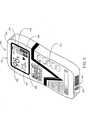
- FIG. 2depicts the use of a Universal/Upgrading Pulse Oximeter ("UPO") 210 to perform patient monitoring.
- a pulse oximetry sensor 110is attached to a patient (not illustrated) and provides the UPO 210 with a modulated red and IR photo-plethysmograph signal through a patient cable 220.
- the UPO 210computes the patient's oxygen saturation and pulse rate from the sensor signal and, optionally, displays the patient's oxygen status.
- the UPO 210may incorporate an internal power source 212, such as common alkaline batteries or a rechargeable power source.
- the UPO 210may also utilize an external power source 214, such as standard 110V AC coupled with an external step-down transformer and an internal or external AC-to-DC converter.
- the UPO 210In addition to providing pulse oximetry measurements, the UPO 210 also separately generates a signal, which is received by a pulse oximeter 268 external to the UPO 210. This signal is synthesized from the saturation calculated by the UPO 210 such that the external pulse oximeter 268 calculates the equivalent saturation and pulse rate as computed by the UPO 210.
- the external pulse oximeter 268 receiving the UPO signalmay be a multiparameter patient monitoring system (MPMS) 260 incorporating a pulse oximeter module 268, a standalone pulse oximeter instrument, or any other host instrument capable of measuring SpO 2 .
- MPMSmultiparameter patient monitoring system
- the UPO 210is connected to an existing MPMS 260 with a cable 230, advantageously integrating the UPO oxygen status measurements with other MPMS measurements. This allows the UPO calculations to be shown on a unified display of important patient parameters, networked with other patient data, archived within electronic patient records and incorporated into alarm management, which are all MPMS functions convenient to the caregiver.
- FIG. 3depicts the major functions of the UPO 210, including an internal pulse oximeter 310, a waveform generator 320, a power supply 330 and an optional display 340.
- Attached to the UPO 210is a sensor 110 and an external pulse oximeter 260.
- the internal pulse oximeter 310provides the sensor 110 with a drive signal 312 that alternately activates the sensor's red and IR LEDs, as is well-known in the art.
- a corresponding detector signal 314is received by the internal pulse oximeter 310.
- the internal pulse oximeter 310computes oxygen saturation, pulse rate, and, in some embodiments, other physiological parameters such as pulse occurrence, plethysmograph features and measurement confidence.
- These parameters 318are output to the waveform generator 320. A portion of these parameters may also be used to generate display drive signals 316 so that patient status may be read from, for example, an LED or LCD display module 340 on the UPO.
- the internal pulse oximeter 310may be a conventional pulse oximeter or, for upgrading an external pulse oximeter 260, it may be an advanced pulse oximeter capable of low perfusion and motion artifact performance not found in conventional pulse oximeters.
- An advanced pulse oximeter for use as an internal pulse oximeter 310is described in U.S. Patent No. 5,632,272 assigned to the assignee of the present invention and incorporated herein by reference.
- An advanced pulse oximetry sensor for use as the sensor 110 attached to the internal pulse oximeter 310is described in U.S. Patent No. 5,638,818 assigned to the assignee of the present invention and incorporated herein by reference.
- a line of advanced Masimo SET ® pulse oximeter OEM boards and sensorsare available from the assignee of the present invention.
- the waveform generator 320synthesizes a waveform, such as a triangular waveform having a sawtooth or symmetric triangle shape, that is output as a modulated signal 324 in response to an input drive signal 322.
- the drive input 322 and modulation output 324 of the waveform generator 320are connected to the sensor port 262 of the external pulse oximeter 260.
- the synthesized waveformis generated in a manner such that the external pulse oximeter 260 computes and displays a saturation and a pulse rate value that is equivalent to that measured by the internal pulse oximeter 310 and sensor 110.
- the waveforms for pulse oximetryare chosen to indicate to the external pulse oximeter 260 a perfusion level of 5%.
- the external pulse oximeter 260therefore, always receives a strong signal.
- the perfusion level of the waveforms synthesized for the external pulse oximetercan be set to indicate a perfusion level at or close to the perfusion level of the patient being monitored by the internal pulse oximeter 310.
- a digital data output 326is connected to the data port 264 of the external pulse oximeter 260. In this manner, saturation and pulse rate measurements and also samples of the unmodulated, synthesized waveform can be communicated directly to the external pulse oximeter 260 for display, bypassing the external pulse oximeter's signal processing functions.
- the measured plethysmograph waveform samples output from the internal pulse oximeter 310also may be communicated through the digital data output 326 to the external pulse oximeter 260.
- the synthesized waveformis not physiological data from the patient being monitored by the internal pulse oximeter 310, but is a waveform synthesized from predetermined stored waveform data to cause the external pulse oximeter 260 to calculate oxygen saturation and pulse rate equivalent to or generally equivalent (within clinical significance) to that calculated by the internal pulse oximeter 310.
- the actual physiological waveform from the patient received by the detectoris not provided to the external pulse oximeter 260 in the present embodiment. Indeed, the waveform provided to the external pulse oximeter will usually not resemble the plethysmographic waveform of physiological data from the patient being monitored by the internal pulse oximeter 260.
- the cable 230 ( FIG. 2 ) attached between the waveform generator 320 and external pulse oximeter 260provides a monitor ID 328 to the UPO, allowing identification of predetermined external pulse oximeter calibration curves.
- this cablemay incorporate an encoding device, such as a resistor, or a memory device, such as a PROM 1010 ( FIG. 10 ) that is read by the waveform generator 320.
- the encoding deviceprovides a value that uniquely identifies a particular type of external pulse oximeter 260 having known calibration curve, LED drive and modulation signal characteristics.
- the wavelengths of the actual sensor 110are not required to correspond to the particular calibration curve indicated by the monitor ID 328 or otherwise assumed for the external pulse oximeter 260. That is, the wavelength of the sensor 110 attached to the internal pulse oximeter 310 is not relevant or known to the external pulse oximeter 260.
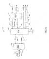
- FIG. 4illustrates one embodiment of the waveform generator portion 320 of the UPO 210 ( FIG. 3 ). Although this embodiment is illustrated and described as hardware, one of ordinary skill will recognize that the functions of the waveform generator may be implemented in software or firmware or a combination of hardware, software and firmware.
- the waveform generator 320performs waveform synthesis with a waveform look-up table ("LUT") 410, a waveform shaper 420 and a waveform splitter 430.
- the waveform LUT 410is advantageously a memory device, such as a ROM (read only memory) that contains samples of one or more waveform portions or segments containing a single waveform.
- These stored waveform segmentsmay be as simple as a single period of a triangular waveform, having a sawtooth or symmetric triangle shape, or more complicated, such as a simulated plethysmographic pulse having various physiological features, for example rise time, fall time and dicrotic notch.
- the waveform shaper 420creates a continuous pulsed waveform from the waveform segments provided by the waveform LUT 410.
- the waveform shaper 420has a shape parameter input 422 and an event indicator input 424 that are buffered 470 from the parameters 318 output from the internal pulse oximeter 310 ( FIG . 3 ).
- the shape parameter input 422determines a particular waveform segment in the waveform LUT 410.
- the chosen waveform segmentis specified by the first address transmitted to the waveform LUT 410 on the address lines 426.
- the selected waveform segmentis sent to the waveform shaper 420 as a series of samples on the waveform data lines 412.
- the event indicator input 424specifies the occurrence of pulses in the plethysmograph waveform processed by the internal pulse oximeter 310 ( FIG. 3 ).
- the event indicatormay be a delta time from the occurrence of a previously detected falling pulse edge or this indicator could be a real time or near real time indicator of the pulse occurrence.
- the waveform shaper 420accesses the waveform LUT 410 in a manner to create a corresponding delta time between pulses in the synthesized waveform output 428.
- the waveform shaperis clocked at a predetermined sample rate.
- the waveform shaper 420determines the number of sequential addresses to skip between samples and accesses the waveform LUT 410 accordingly. This effectively “stretches” or “shrinks” the retrieved waveform segment so as to fit in the time between two consecutive pulses detected by the UPO.
- the waveform splitter 430creates a first waveform 432 corresponding to a first waveform (such a red wavelength) expected by the external pulse oximeter 260 ( Fig. 3 ) and a second waveform (such as infrared) 434 expected by the external pulse oximeter 260.
- the relative amplitudes of the first waveform 432 and second waveform 434are adjusted to correspond to the ratio output 444 from a calibration curve LUT 440.
- the calibration curve LUT 440provides a corresponding ratio output 444 that results in the first waveform 432 and the second waveform 434 having an amplitude ratio that will be computed by the external pulse oximeter 260 ( FIG. 3 ) as equivalent to the oxygen saturation measured by the internal pulse oximeter 310 ( FIG. 3 ).
- the operating wavelengths of the sensor 110are not relevant to the operating wavelengths required by the external pulse oximeter 260 ( FIG. 3 ), i.e. the operating wavelengths that correspond to the calibration curve or curves utilized by the external pulse oximeter.
- the calibration curve LUT 440simply permits generation of a synthesized waveform as expected by the external oximeter 260 ( FIG. 3 ) based on the calibration curve used by the external pulse oximeter 260 ( FIG. 3 ).
- the calibration curve LUT 440contains data about the known calibration curve of the external pulse oximeter 260 ( FIG. 3 ), as specified by the monitor ID input 328.
- the waveform actually synthesizedis not a patient plethysmographic waveform. It is merely a stored waveform that will cause the external pulse oximeter to calculate the proper oxygen saturation valve and pulse rate values.. Although this does not provide a patient plethysmograph on the external pulse oximeter for the clinician, the calculated values, which is what is actually sought, will be accurate.
- a modulator 450responds to an LED drive input 322 to generate a modulated waveform output 324 derived from the first waveform 432 and second waveform 434. Also, a data communication interface 460 transmits as a digital data output 326 the data obtained from the sat 442, pulse rate 462 and synthesized waveform 428 inputs.
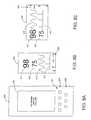
- FIG. 5depicts a handheld UPO 500 embodiment.
- the handheld UPO 500has keypad inputs 510, an LCD display 520, an external power supply input 530, an output port 540 for connection to an external pulse oximeter and a sensor input 550 at the top edge (not visible).
- the display 520shows the measured oxygen saturation 522, the measured pulse rate 524, a pulsating bar 526 synchronized with pulse rate or pulse events, and a confidence bar 528 indicating confidence in the measured values of saturation and pulse rate. Also shown are low battery 572 and alarm enabled 574 status indicators.
- the handheld embodiment described in connection with FIG. 5may also advantageously function in conjunction with a docking station that mechanically accepts, and electrically connects to, the handheld unit.
- the docking stationmay be co-located with a patient monitoring system and connected to a corresponding SpO 2 module sensor port, external power supply, printer and telemetry device, to name a few options.
- the handheld UPOmay be removed from a first docking station at one location to accompany and continuously monitor a patient during transport to a second location.
- the handheld UPOcan then be conveniently placed into a second docking station upon arrival at the second location, where the UPO measurements are displayed on the patient monitoring system at that location.
- FIG. 6shows a block diagram of a UPO embodiment, where the functions of the UPO 210 are split between a portable pulse oximeter 610 and a docking station 660.
- the portable pulse oximeter 610(“portable") is a battery operated, fully functional, stand-alone pulse oximeter instrument.
- the portable 610connects to a sensor 110 ( FIG. 2 ) through a UPO patient cable 220 ( FIG. 2 ) attached to a patient cable connector 618.
- the portable 610provides the sensor 110 with a drive signal 612 that alternately activates the sensor's red and IR LEDs, as is well-known in the art.
- the portablealso receives a corresponding detector signal 614 from the sensor.
- the portablecan also input a sensor ID on the drive signal line 612, as described in U.S. Patent No. 5,758,644 entitled Manual and Automatic Probe Calibration, assigned to the assignee of the present invention and incorporated herein by reference.
- the portable 610can be installed into the docking station 660 to expand its functionality. When installed, the portable 610 can receive power 662 from the docking station 660 if the docking station 660 is connected to external power 668. Alternately, with no external power 668 to the docking station 660, the portable 610 can supply power 662 to the docking station 660.
- the portable 610communicates to the docking station with a bidirectional serial data line 664.
- the portable 610provides the docking station with SpO 2 , pulse rate and related parameters computed from the sensor detector signal 614.
- the docking station 660may drive a host instrument 260 ( FIG. 2 ) external to the portable 610.
- the portable 610 and docking station 660 combinationmay function as a standalone pulse oximeter instrument, as described below with respect to FIG. 13 .
- the docking station 660does not perform any action when the portable 610 is not docked.
- the user interface for the docking station 660i.e. keypad and display, is on the portable 610.
- An indicator LED on the docking station 660is lit when the portable is docked.
- the docking station 660generates a detector signal output 674 to the host instrument 260 ( FIG. 2 ) in response to LED drive signals 672 from the host instrument and SpO 2 values and related parameters received from the portable 610.
- the docking station 660also provides a serial data output 682, a nurse call 684 and an analog output 688.
- An interface cable 690connects the docking station 660 to the host instrument patient cable 230 ( FIG. 2 ).
- the LED drive signals 672 and detector signal output 674are communicated between the docking station 660 and the host instrument 260 ( FIG. 2 ) via the interface cable 690.
- the interface cable 690provides a sync data output 692 to the docking station 660, communicating sensor, host instrument (e.g. monitor ID 328, FIG. 3 ) and calibration curve data.
- this dataallows the docking station 660 to appear to a particular-host instrument as a particular sensor providing patient measurements.
- FIG. 7provides further detail of the portable 610.
- the portable componentsinclude a pulse oximeter processor 710, a management processor 720, a power supply 730, a display 740 and a keypad 750.
- the pulse oximeter processor 710functions as an internal pulse oximeter, interfacing the portable to a sensor 110 ( FIG. 2 ) and deriving SpO 2 , pulse rate, a plethysmograph and a pulse indicator.
- An advanced pulse oximeter for use as the pulse oximeter processor 710is described in U.S. Patent No. 5,632,272 , referenced above.
- An advanced pulse oximetry sensor for use as the sensor 110 ( FIG. 2 ) attached to the pulse oximeter processor 710is described in U.S. Patent No.
- the pulse oximeter processor 710is the Masimo SET ® MS-3L board or a low power MS-5 board.
- the management processor 720controls the various functions of the portable 610, including asynchronous serial data communications 724 with the pulse oximeter processor 710 and synchronous serial communications 762 with the docking station 660 ( FIG. 6 ).
- the physical and electrical connection to the docking station 660 ( FIG. 6 )is via a docking station connector 763 and the docking station interface 760, respectively.
- the processor 720utilizes a real-time clock 702 to keep the current date and time, which includes time and date information that is stored along with SpO 2 parameters to create trend data.
- the processor of the portable 610 and the docking station 660 ( FIG. 6 )can be from the same family to share common routines and minimize code development time.
- the processor 720also controls the user interface 800 ( FIG. 8A ) by transferring data 742 to the display 740, including display updates and visual alarms, and by interpreting keystroke data 752 from the keypad 750.
- the processor 720generates various alarm signals, when required, via an enable signal 728, which controls a speaker driver 770.
- the speaker driver 770actuates a speaker 772, which provides audible indications such as, for example, alarms and pulse beeps.
- the processor 720also monitors system status, which includes battery status 736, indicating battery levels, and docked status 764, indicating whether the portable 610 is connected to the docking station 660 ( FIG. 6 ). When the portable 610 is docked and is on, the processor 720 also decides when to turn on or off docking station power 732.
- the caregivercan set (i.e. configure or program) the behavior of the portable display 740 and alarms when the docked portable 610 senses that an interface cable 690 has connected the docking station 660 to an external pulse oximeter, such as a multiparameter patient monitoring system.
- the portable display 740stops showing the SpO 2 811 ( FIG. 8 ) and pulse rate 813 ( FIG. 8 ) values when connected to an external pulse oximeter to avoid confusing the caregiver, who can read equivalent values on the patient monitoring system.
- the display 740continues to show the plethysmograph 815 ( FIG. 8 ) and visual pulse indicator 817 ( FIG. 8 ) waveforms.
- the portable alarmsremain active.
- Another task of the processor 720includes maintenance of a watchdog function.
- the watchdog 780monitors processor status on the watchdog data input 782 and asserts the ⁇ P reset output 784 if a fault is detected. This resets the management processor 720, and the fault is indicated with audible and visual alarms.
- the portable 610gets its power from batteries in the power supply 730 or from power 766 supplied from the docking station 660 ( FIG. 6 ) via the docking station interface 760.
- a power manager 790monitors the on/off switch on the keypad 750 and turns-on the portable power accordingly.
- the power manager 790turns off the portable on command by the processor 720.
- DC/DC converters within the power supply 730generate the required voltages 738 for operation of the portable 610 and docking station power 732.
- the portable batteriescan be either alkaline rechargeable batteries or another renewable power source:
- the batteries of the power supply 730supply docking station power 732 when the docking station 660 ( FIG. 6 ) is without external power.
- a battery charger within the docking station power supplyprovides charging current 768 to rechargeable batteries within the power supply 730.
- the docking station power supply 990( FIG. 9 ) monitors temperature 734 from a thermistor in the rechargeable battery pack, providing an indication of battery charge status.
- a non-volatile memory 706is connected to the management processor 720 via a high-speed bus 722.
- the memory 706is an erasable and field re-programmable device used to store boot data, manufacturing serial numbers, diagnostic failure history, adult SpO 2 and pulse rate alarm limits, neonate SpO 2 and pulse rate alarm limits, SpO 2 and pulse rate trend data, and program data. Other types of non-volatile memory are well known.
- the SpO 2 and pulse rate alarm limits, as well as SpO 2 related algorithm parameters,may be automatically selected based on the type of sensor 110 ( FIG. 2 ), adult or neonate, connected to the portable 610.
- the LCD display 740employs LEDs for a backlight to increase its contrast ratio and viewing distance when in a dark environment.
- the intensity of the backlightis determined by the power source for the portable 610.
- the portable 610is powered by either a battery pack within its power supply 730 or a battery pack in the docking station power supply 990 ( FIG. 9 )
- the backlight intensityis at a minimum level.
- the portable 610is powered by external power 668 ( FIG. 6 )
- the backlightis at a higher intensity to increase viewing distance and angle.
- button on the portablepermits overriding these intensity settings, and provides adjustment of the intensity.
- the backlightis controlled in two ways.
- the backlightWhenever any key is pressed, the backlight is illuminated for a fixed number of seconds and then turns off, except when the portable is docked and derives power from an external source. In that case, the backlight is normally on unless deactivated with a key on the portable 610.
- FIG. 8Aillustrates the portable user interface 800, which includes a display 740 and a keypad 750.
- the display 740is a dot matrix LCD device having 160 pixels by 480 pixels.
- the display 740can be shown in portrait mode, illustrated in FIG. 8B , or in landscape mode, illustrated in FIG. 8C .
- a tilt sensor 950 ( FIG. 9 ) in the docking station 660 ( FIG. 6 ) or a display mode key on the portable 610 ( FIG. 6 )determines portrait or landscape mode.
- the tilt sensor 950 ( FIG. 9 )can be a gravity-activated switch or other device responsive to orientation and can be alternatively located in the portable 610 ( FIG. 6 ).
- the tilt sensor 950FIG.
- the tilt sensor 950( FIG. 9 ) could also be a mercury tilt switch.
- FIGS. 8B and 8CExamples of how the display area can be used to display SpO 2 811, pulse rate 813, a plethysmographic waveform 815, a visual pulse indicator 817 and soft key icons 820 in portrait and landscape mode are shown in FIGS. 8B and 8C , respectively.
- the software program of the management processor 720( FIG. 7 ) can be easily changed to modify the category, layout and size of the display information shown in FIGS. 8B ⁇ C.
- Other advantageous information for displayis SpO 2 limits, alarm, alarm disabled, exception messages and battery status.
- the keypad 750includes soft keys 870 and fixed keys 880.
- the fixed keys 880each have a fixed function.
- the soft keys 870each have a function that is programmable and indicated by one of the soft key icons 820 located next to the soft keys 870. That is, a particular one of the soft key icons 820 is in proximity to a particular one of the soft keys 870 and has a text or a shape that suggests the function of that particular one of the soft keys 870.
- the button portion of each key of the keypad 750is constructed of florescent material so that the keys 870, 880 are readily visible in the dark.
- the keypad 750has one row of four soft keys 870 and one row of three fixed keys 880.
- the functions of the three fixed keys 880are power, alarm silence and light/contrast.
- the power functionis an on/off toggle button.
- the alarm silence function and the light/contrast functionhave dual purposes depending on the duration of the key press. A momentary press of the key corresponding to the alarm silence function will disable the audible alarm for a fixed period of time. To disable the audible alarm indefinitely, the key corresponding to the alarm silence function is held down for a specified length of time.
- the audible alarmis reactivated. If the key corresponding to the light/contrast function is pressed momentarily, it is an on/off toggle button for the backlight. If the key corresponding to the light/contrast function is held down, the display contrast cycles through its possible values.
- the default functions of the four soft keys 870are pulse beep up volume, pulse beep down volume, menu select, and display mode. These functions are indicated on the display by the up arrow, down arrow, "menu" and curved arrow soft key icons 820, respectively.
- the up volume and down volume functionsincrease or decrease the audible sound or "beep" associated with each detected pulse.
- the display mode functionrotates the display 740 through all four orthogonal orientations, including portrait mode ( FIG. 8B ) and landscape mode ( FIG. 8C ), with each press of the corresponding key.
- the menu select functionallows the functionality of the soft keys 870 to change from the default functions described above.
- Examples of additional soft key functionsthat can be selected using this menu feature are set SpO 2 high/low limit, set pulse rate high/low limit, set alarm volume levels, set display to show trend data, print trend data, erase trend data, set averaging time, set sensitivity mode, perform synchronization, perform rechargeable battery maintenance (deep discharge/recharge to remove battery memory), and display product version number.
- FIG. 9provides further details of the docking station 660, which includes a docking station processor 910, a non-volatile memory 920, a waveform generator 930, a PROM interface 940, a tilt sensor 950, a portable interface 970 and associated connector 972, status indicators 982, a serial data port 682, a nurse call output 684, an analog output 688 and a power supply 990.
- the docking station 660is intended to be associated with a fixed (non-transportable) host instrument, such as a multiparameter patient monitoring instrument in a hospital emergency room.
- the docking station 660is movable, and includes a battery pack within the power supply 990.
- the docking station processor 910orchestrates the activity on the docking station 660.
- the processor 910provides the waveform generator 930 with parameters 932 as discussed above for Figures 3 and 4 .
- the processor 910also provides asynchronous serial data 912 for communications with external devices and synchronous serial data 971 for communications with the portable 610 ( FIG. 6 ).
- the processor 910determines system status including sync status 942, tilt status 952 and power status 992.
- the portable management processor 720( FIG. 7 ) performs the watchdog function for the docking station processor 910.
- the docking station processor 910sends watchdog messages to the portable processor 720 ( FIG. 7 ) as part of the synchronous serial data 972 to ensure the correct operation of the docking station processor 910.
- the docking station processor 910accesses non-volatile memory 920 over a high-speed bus 922.
- the non-volatile memory 920is re-programmable and contains program data for the processor 910 including instrument communication protocols, synchronization information, a boot image, manufacturing history and diagnostic failure history.
- the waveform generator 930generates a synthesized waveform that a conventional pulse oximeter can process to calculate SpO 2 and pulse rate values or exception messages, as described above with respect to FIG. 4 .
- the waveform generator outputdoes not reflect a physiological waveform. It is merely a waveform constructed to cause the external pulse oximeter to calculate the correct saturation and pulse rate..
- physiological datacould be provided to the external pulse oximeter, but the external pulse oximeter would generally not be able to calculate the proper saturation values, and the upgrading feature would be lost.
- the waveform generator 930is enabled if an interface cable 690 ( FIG. 6 ), described below with respect to FIG. 10 , with valid synchronization information is connected. Otherwise, the power to the waveform generator 930 is disabled.
- the status indicators 982are a set of LEDs on the front of the docking station 660 used to indicate various conditions including external power (AC), portable docked, portable battery charging, docking station battery charging and alarm.
- the serial data port 682is used to interface with either a computer, a serial port of conventional pulse oximeters or serial printers via a standard RS-232 DB-9 connector 962. This port 682 can output trend memory, SpO 2 and pulse rate and support the system protocols of various manufacturers.
- the analog output 688is used to interface with analog input chart recorders via a connector 954 and can output "real-time" or trend SpO 2 and pulse rate data.
- the nurse call output 684 from a connector 964is activated when alarm limits are exceeded for a predetermined number of consecutive seconds. In another embodiment, data, including alarms, could be routed to any number of communications ports, and even over the internet, to permit remote use of the upgrading pulse oximeter.
- the PROM interface 940accesses synchronization data 692 from the PROM 1010 ( FIG. 10 ) in the interface cable 690 ( FIGS. 6, 10 ) and provides synchronization status 942 to the docking station processor 910.
- the portable interface 970provides the interconnection to the portable 610 ( FIG. 6 ) through the docking station interface 760 ( FIG. 7 ).
- external power 668is provided to the docking station 660 through a standard AC connector 968 and on/off switch 969.
- the power supply 990charges the battery in the portable power supply 730 ( FIG. 7 ) and the battery, if any, in the docking station power supply 990.
- the portable 610FIG. 6
- the docking station power 973is removed and the docking station 660 is turned off, except for the battery charger portion of the power supply 990.
- the docking station power 973 and, hence, the docking station 660turn on whenever a docked portable 610 ( FIG. 6 ) is turned on.
- the portable 610( FIG. 6 ) supplies power for an embodiment of the docking station 660 without a battery when external power 668 is removed or fails.
- FIG. 10provides further detail regarding the interface cable 690 used to connect between the docking station 660 ( FIG. 6 ) and the patient cable 230 ( FIG. 2 ) of a host instrument 260 ( FIG. 2 ).
- the interface cable 690is configured to interface to a specific host instrument and to appear to the host instrument as a specific sensor.
- a PROM 1010 built into the interface cable 690contains information identifying a sensor type, a specific host instrument, and the calibration curve of the specific host instrument.
- the PROM informationcan be read by the docking station 660 ( FIG. 6 ) as synchronization data 692.
- the synchronization data 692allows the docking station 660 ( FIG.
- the interface cable 690includes an LED drive path 672.
- the LED drive path 672is configured for common anode LEDs and includes IR cathode, red cathode and common anode signals.
- the interface cable 690also includes a detector drive path 674, including detector anode and detector cathode signals.
- a menu option on the portable 610also allows synchronization information to be calculated in the field.
- the docking station 660With manual synchronization, the docking station 660 ( FIG. 6 ) generates a waveform to the host instrument 260 ( FIG. 2 ) and displays an expected SpO 2 value. The user enters the SpO 2 value displayed on the host instrument using the portable keypad 750 ( FIG. 7 ). These steps are repeated until a predetermined number of data points are entered and the SpO 2 values displayed by the portable and the host instrument are consistent.
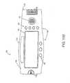
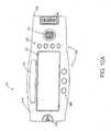
- FIGS. 11A-Bdepict an embodiment of the portable 610, as described above with respect to FIG. 6 .
- FIGS. 12A-Bdepict an embodiment of the docking station 660, as described above with respect to FIG 6 .
- FIG. 13depicts an embodiment of the UPO 210 where the portable 610 is docked with the docking station 660, also as described above with respect to FIG. 6 .
- FIG. 11Adepicts the portable front panel 1110.
- the portable 610has a patient cable connector 618, as described above with respect to FIG. 6 .
- the connector 618is rotatably mounted so as to minimize stress on an attached patient cable (not shown).
- the connector 618can freely swivel between a plane parallel to the front panel 1110 and a plane parallel to the side panel 1130.
- the connector 618can swivel between, and be releasably retained in, three locked positions.
- a first locked positionis as shown, where the connector is in a plane parallel to the front panel 1110.
- a second locked positionis where the connector 618 is in a plane parallel to the side panel 1130.
- the connector 618also has an intermediate locked position 45° between the first and the second locked positions.
- the connector 618is placed in the first locked position for attachment to the docking station 660.
- the portable front panel 1110also has a speaker 772, as described with respect to FIG. 7 .
- the front panel 1110has a row of soft keys 870 and fixed keys 880, as described above with respect to FIG. 8 .
- the front panel 1110has a finger actuated latch 1120 that locks onto a corresponding catch 1244 ( FIG. 12A ) in the docking station 660, allowing the portable 610 to be releasably retained by the docking station 660.
- An OEM labelcan be affixed to a recessed area 1112 on the front panel 1110.
- FIG. 11Bdepicts the portable back panel 1140.
- the back panel 1140has a socket 763, a pole clamp mating surface 1160, and a battery pack compartment 1170.
- the socket 763is configured to mate with a corresponding docking station plug 972 ( FIG. 12A ).
- the socket 763 and plug 972( FIG. 12A ) provide the electrical connection interface between the portable 610 and the docking station 660 ( FIG. 12A ).
- the socket 763houses multiple spring contacts that compress against plated edge-connector portions of the docking station plug 972 ( FIG. 12A ).
- a conventional pole clamp(not shown) may be removably attached to the mating surface 1160.
- the portable power supply 730( FIG. 7 ) is contained within the battery pack compartment 1170.
- the compartment 1170has a removable cover 1172 for protection, insertion and removal of the portable battery pack.
- Product labelssuch as a serial number identifying a particular portable, can be affixed with the back panel indent 1142.
- FIG. 12Adepicts the front side 1210 of the docking station 660.
- the front side 1210has a docking compartment 1220, a pole clamp recess 1230, pivots 1242, a catch 1244, a plug connector 972 and LED status indicators 982.
- the docking compartment 1220accepts and retains the portable 610 ( FIGS. 11A-B ), as shown in FIG. 13 .
- the pole clamp recess 1230accommodates a pole clamp (not shown) attached to the portable's pole clamp mating surface 1160 ( FIG. 11B ), assuming the pole clamp is in its closed position.
- the portable 610FIGS.
- FIGS. 11A ⁇ Bis retained in the compartment 1220 by pivots 1242 that fit into corresponding holes in the portable's side face 1130 and a catch 1244 that engages the portable's latch 1120 ( FIG. 11A ).
- the portable 610FIGS. 11A-B
- the portable 610FIGS. 11A-B
- the portable 610is undocked in reverse order, by first pressing the latch 1120 ( FIG. 11A ), which releases the portable from the catch 1244, rotating the portable 610 ( FIGS.
- the docking station plug 972inserts into the portable socket 763 ( FIG. 11B ), providing the electrical interface between the portable 610 and the docking station 660.
- the status indicators 982are as described above with respect to FIG. 9 .
- FIG. 12Bdepicts the back side 1260 of the docking station 660.
- the back side 1260has a serial (RS ⁇ 232 or USB) connector 962, an analog output and nurse call connector 964, an upgrade port connector 966, an AC power plug 968, an on/off switch 969 and a ground lug 1162.
- a handle 1180is provided at one end and fan vents 1170 are provided at the opposite end.
- a pair of feet 1190are visible near the back side 1260.
- a corresponding pair of feet(not visible) are located near the front side 1210 ( FIG. 12A ). The feet near the front side 1210 extend so as to tilt the front side 1210 ( FIG. 12A ) upward, making the display 740 ( FIG. 13 ) of a docked portable 610 ( FIG. 13 ) easier to read.
- FIG. 13illustrates both the portable 610 and the docking station 660.
- the portable 610 and docking station 660constitute three distinct pulse oximetry instruments.
- the portable 610 by itself, as depicted in FIGS. 11A-Bis a handheld pulse oximeter applicable to various patient monitoring tasks requiring battery power or significant mobility, such as ambulance and ER situations.
- the portable 610 docked in the docking station 660as depicted in FIG. 13 , is a standalone pulse oximeter applicable to a wide-range of typical patient monitoring situations from hospital room to the operating room.
- the portable 610 docked and the upgrade port 966FIG. 12B
- the upgrade port 966FIG. 12B
- UPOuniversal/upgrading pulse oximeter
- the docking station 660incorporates an input port that connects to a blood pressure sensor and an output port that connects to the blood pressure sensor port of a multiparameter patient monitoring system (MPMS).
- the docking station 660incorporates a signal processor that computes a blood pressure measurement based upon an input from the blood pressure sensor.
- the docking station 660also incorporates a waveform generator connected to the output port that produces a synthesized waveform based upon the computed measurement.
- the waveform generator outputis adjustable so that the blood pressure value displayed on the MPMS is equivalent to the computed blood pressure measurement.
- the portable 610is docked in the docking station 660 and the blood pressure sensor is connected to the input port, the portable displays a blood pressure value according to the computed blood pressure measurement.
- the docking station 660provides universal/upgrading capability for both blood pressure and SpO 2 .
- the docking station 660can function as an universal/upgrading instrument for other vital sign measurements, such as respiratory rate, EKG or EEG.
- the docking station 660incorporates related sensor connectors and associated sensor signal processors and upgrade connectors to an MPMS or standalone instrument.
- a variety of vital sign measurementscan be incorporated into the docking station 660, either individually or in combination, with or without SpO 2 as a measurement parameter, and with or without the portable 610.
- the docking station 660can be configured as a simple SpO 2 upgrade box, incorporating a SpO 2 processor and patient cable connector for a SpO 2 sensor that functions with or without the portable 610.
- the standalone configuration shown in FIG. 13has a rotatable display 740 that allows the instrument to be operated in either a vertical or horizontal orientation.
- a tilt sensor 950( FIG. 9 ) indicates when the bottom face 1310 is placed along a horizontal surface or is otherwise horizontally-oriented. In this horizontal orientation, the display 740 appears in landscape mode ( FIG. 8C ).
- the tilt sensor 950( FIG. 9 ) also indicates when the side face 1320 is placed along a horizontal surface or is otherwise horizontally oriented. In this vertical orientation, the display 740 appears in portrait mode ( FIG. 8B ).
- a soft key 870 on the portable 610can override the tilt sensor, allowing the display to be presented at any 90° orientation, i.e.
- the handheld configuration( FIG. 11A ), can also present the display 740 at any 90° orientation using a soft key 870.
- the portable 610does not have a tilt sensor and, hence, relies on a soft key 870 to change the orientation of the display when not docked.
- FIG. 14illustrates the docking station 660 incorporated within a local area network (LAN).
- the LAN shownis Ethernet-based 1460, using a central LAN server 1420 to interconnect various LAN clients 1430 and other system resources such as printers and storage (not shown).
- An Ethernet controller module 1410is incorporated with the docking station 660.
- the controller module 1410can be incorporated within the docking station 660 housing or constructed as an external unit. In this manner, the UPO, according to the present invention, can communicate with other devices on the LAN or over the Internet 1490.
- the Ethernet controller module 1410can be embedded with web server firmware, such as the Hewlett-Packard (HP) BFOOT-10501.
- the module 1410has both a 10 Base-T Ethernet interface for connection to the Ethernet 1460 and a serial interface, such as RS-232 or USB, for connection to the docking station 660.
- the module firmwareincorporates HTTP and TCP/IP protocols for standard communications over the World Wide Web.
- the firmwarealso incorporates a micro web server that allows custom web pages to be served to remote clients over the Internet, for example. Custom C++ programming allows expanded capabilities such as data reduction, event detection and dynamic web page configuration.
- the docking station 660there are many applications for the docking station 660 to Ethernet interface.
- Multiple UPOscan be connected to a hospital's LAN, and a computer on the LAN could be utilized to upload pulse rate and saturation data from the various UPOs, displaying the results.
- this Ethernet interfacecould be used to implement a central pulse oximetry monitoring station within a hospital.
- multiple UPOs from anywhere in the worldcan be monitored from a central location via the Internet.
- Each UPOis addressable as an individual web site and downloads web pages viewable on a standard browser, the web pages displaying oxygen saturation, pulse rate and related physiological measurements from the UPO. This feature allows a caregiver to monitor a patient regardless of where the patient or caregiver is located.
- a caregiver located at home in one city or at a particular hospitalcould download measurements from a patient located at home in a different city or at the same or a different hospital.
- Other applicationsinclude troubleshooting newly installed UPOs or uploading software patches or upgrades to UPOs via the Internet.
- alarmscould be forwarded to the URL of the clinician monitoring the patient.
- the UPOmay have other configurations besides the handheld unit described in connection with FIG. 5 or the portable 610 and docking station 660 combination described in connection with FIGS. 11-13 .
- the UPOmay be a module, with or without a display, that can be removably fastened to a patient via an arm strap, necklace or similar means. In a smaller embodiment, this UPO module may be integrated into a cable or connector used for attaching a sensor to a pulse oximeter.
- the UPOmay also be a circuit card or module that can externally or internally plug into or mate with a standalone pulse oximeter or multiparameter patient monitoring system. Alternatively, the UPO may be configured as a simple standalone upgrade instrument.
- a universal/upgrading apparatus and methodhave been mainly described in terms of a pulse oximetry measurement embodiment, the present invention is equally applicable to other physiological measurement parameters such as blood pressure, respiration rate, EEG and ECG, to name a few.
- a universal/upgrading instrumenthaving a single physiological measurement parameter or a multiple measurement parameter capability and configured as a handheld, standalone, portable, docking station, module, plug-in, circuit card, to name a few, is also within the scope of the present invention.
Landscapes
- Health & Medical Sciences (AREA)
- Life Sciences & Earth Sciences (AREA)
- Engineering & Computer Science (AREA)
- Physics & Mathematics (AREA)
- Biomedical Technology (AREA)
- General Health & Medical Sciences (AREA)
- Medical Informatics (AREA)
- Public Health (AREA)
- Veterinary Medicine (AREA)
- Heart & Thoracic Surgery (AREA)
- Molecular Biology (AREA)
- Surgery (AREA)
- Animal Behavior & Ethology (AREA)
- Biophysics (AREA)
- Pathology (AREA)
- Optics & Photonics (AREA)
- Computer Networks & Wireless Communication (AREA)
- Spectroscopy & Molecular Physics (AREA)
- Epidemiology (AREA)
- General Business, Economics & Management (AREA)
- Primary Health Care (AREA)
- Business, Economics & Management (AREA)
- Measurement Of The Respiration, Hearing Ability, Form, And Blood Characteristics Of Living Organisms (AREA)
- Measuring Pulse, Heart Rate, Blood Pressure Or Blood Flow (AREA)
- Measuring And Recording Apparatus For Diagnosis (AREA)
- Investigating Or Analysing Materials By Optical Means (AREA)
- Magnetic Treatment Devices (AREA)
- Magnetic Resonance Imaging Apparatus (AREA)
- Electrotherapy Devices (AREA)
Abstract
Description
- Oximetry is the measurement of the oxygen level status of blood. Early detection of low blood oxygen level is critical in the medical field, for example in critical care and surgical applications, because an insufficient supply of oxygen can result in brain damage and death in a matter of minutes. Pulse oximetry is a widely accepted noninvasive procedure for measuring the oxygen saturation level of arterial blood, an indicator of oxygen supply. A pulse oximetry system consists of a sensor applied to a patient, a pulse oximeter, and a patient cable connecting the sensor and the pulse oximeter.
- The pulse oximeter may be a standalone device or may be incorporated as a module or built-in portion of a multiparameter patient monitoring system, which also provides measurements such as blood pressure, respiratory rate and EKG. A pulse oximeter typically provides a numerical readout of the patient's oxygen saturation, a numerical readout of pulse rate, and an audible indicator or "beep" that occurs in response to each pulse. In addition, the pulse oximeter may display the patient's plethysmograph, which provides a visual display of the patient's pulse contour and pulse rate.
FIG.1 illustrates a priorart pulse oximeter 100 and associatedsensor 110. Conventionally, apulse oximetry sensor 110 hasLED emitters 112, typically one at a red wavelength and one at an infrared wavelength, and aphotodiode detector 114. Thesensor 110 is typically attached to an adult patient's finger or an infant patient's foot. For a finger, thesensor 110 is configured so that theemitters 112 project light through the fingernail and through the blood vessels and capillaries underneath. TheLED emitters 112 are activated bydrive signals 122 from thepulse oximeter 100. Thedetector 114 is positioned at the fingertip opposite the fingernail so as to detect the LED emitted light as it emerges from the finger tissues. The photodiode generatedsignal 124 is relayed by a cable to thepulse oximeter 100.- The
pulse oximeter 100 determines oxygen saturation (SpO2) by computing the differential absorption by arterial blood of the two wavelengths emitted by thesensor 110. Thepulse oximeter 100 contains asensor interface 120, an SpO2 processor130, aninstrument manager 140, adisplay 150, an audible indicator (tone generator)160 and akeypad 170. Thesensor interface 120 providesLED drive current 122 which alternately activates the sensor red andIR LED emitters 112. Thesensor interface 120 also has input circuitry for amplification and filtering of thesignal 124 generated by thephotodiode detector 114, which corresponds to the red and infrared light energy attenuated from transmission through the patient tissue site. The SpO2processor 130 calculates a ratio of detected red and infrared intensities, and an arterial oxygen saturation value is empirically determined based on that ratio. Theinstrument manager 140 provides hardware and software interfaces for managing thedisplay 150,audible indicator 160 andkeypad 170. Thedisplay 150 shows the computed oxygen status, as described above. Theaudible indicator 160 provides the pulse beep as well as alarms indicating desaturation events. Thekeypad 170 provides a user interface for such things as alarm thresholds, alarm enablement, and display options. - Computation of SpO2 relies on the differential light absorption of oxygenated hemoglobin, HbO2, and deoxygenated hemoglobin, Hb, to determine their respective concentrations in the arterial blood. Specifically, pulse oximetry measurements are made at red and IR wavelengths chosen such that deoxygenated hemoglobin absorbs more red light than oxygenated hemoglobin, and, conversely, oxygenated hemoglobin absorbs more infrared light than deoxygenated hemoglobin, for example 660 nm (red) and 905 nm (IR).
- To distinguish between tissue absorption at the two wavelengths, the red and
IR emitters 112 are provideddrive current 122 so that only one is emitting light at a given time. For example, theemitters 112 may be cycled on and off alternately, in sequence, with each only active for a quarter cycle and with a quarter cycle separating the active times. This allows for separation of red and infrared signals and removal of ambient light levels by downstream signal processing. Because only asingle detector 114 is used, it responds to both the red and infrared emitted light and generates a time-division-multiplexed ("modulated")output signal 124. This modulatedsignal 124 is coupled to the input of thesensor interface 120. - In addition to the differential absorption of hemoglobin derivatives, pulse oximetry relies on the pulsatile nature of arterial blood to differentiate hemoglobin absorption from absorption of other constituents in the surrounding tissues. Light absorption between systole and diastole varies due to the blood volume change from the inflow and outflow of arterial blood at a peripheral tissue site. This tissue site might also comprise skin, muscle, bone, venous blood, fat, pigment, etc., each of which absorbs light. It is assumed that the background absorption due to these surrounding tissues is invariant and can be ignored. Thus, blood oxygen saturation measurements are based upon a ratio of the time-varying or AC portion of the detected red and infrared signals with respect to the time-invariant or DC portion:

- Pulse oximetry is the standard-of-care in various hospital and emergency treatment environments. Demand has lead to pulse oximeters and sensors produced by a variety of manufacturers. Unfortunately, there is no standard for either performance by, or compatibility between, pulse oximeters or sensors. As a result, sensors made by one manufacturer are unlikely to work with pulse oximeters made by another manufacturer. Further, while conventional pulse oximeters and sensors are incapable of taking measurements on patients with poor peripheral circulation and are partially or fully disabled by motion artifact, advanced pulse oximeters and sensors manufactured by the assignee of the present invention are functional under these conditions. This presents a dilemma to hospitals and other caregivers wishing to upgrade their patient oxygenation monitoring capabilities. They are faced with either replacing all of their conventional pulse oximeters, including multiparameter patient monitoring systems, or working with potentially incompatible sensors and inferior pulse oximeters manufactured by various vendors for the pulse oximetry equipment in use at the installation.
- Hospitals and other caregivers are also plagued by the difficulty of monitoring patients as they are transported from one setting to another. For example, a patient transported by ambulance to a hospital emergency room will likely be unmonitored during the transition from ambulance to the ER and require the removal and replacement of incompatible sensors in the ER. A similar problem is faced within a hospital as a patient is moved between surgery, ICU and recovery settings. Incompatibility and transport problems are exacerbated by the prevalence of expensive and non-portable multiparameter patient monitoring systems having pulse oximetry modules as one measurement parameter.
- The Universal/Upgrading Pulse Oximeter (UPO) according to the present invention is focused on solving these performance, incompatibility and transport problems. The UPO provides a transportable pulse oximeter that can stay with and continuously monitor the patient as they are transported from setting to setting. Further, the UPO provides a synthesized output that drives the sensor input of other pulse oximeters. This allows the UPO to function as a universal interface that matches incompatible sensors with other pulse oximeter instruments. Further, the UPO acts as an upgrade to existing pulse oximeters that are adversely affected by low tissue perfusion and motion artifact. Likewise, the UPO can drive a SpO2 sensor input of multiparameter patient monitoring systems, allowing the UPO to integrate into the associated multiparameter displays, patient record keeping systems and alarm management functions.
- One aspect of the present invention is a measurement apparatus comprising a sensor, a first pulse oximeter and a waveform generator. The sensor has at least one emitter and an associated detector configured to attach to a tissue site. The detector provides an intensity signal responsive to the oxygen content of arterial blood at the tissue site. The first pulse oximeter is in communication with the detector and computes an oxygen saturation measurement based on the intensity signal. The waveform generator is in communication with the first pulse oximeter and provides a waveform based on the oxygen saturation measurement. A second pulse oximeter is in communication with the waveform generator and displays an oxygen saturation value based on the waveform. The waveform is synthesized so that the oxygen saturation value is generally equivalent to the oxygen saturation measurement.
- In another aspect of the present invention, a measurement apparatus comprises a first sensor port connectable to a sensor, an upgrade port, a signal processor and a waveform generator. The upgrade port is connectable to a second sensor port of a physiological monitoring apparatus. The signal processor is configured to compute a physiological measurement based on a signal input to the first sensor port. The waveform generator produces a waveform based on the physiological measurement, and the waveform is available at the upgrade port. The waveform is adjustable so that the physiological monitoring apparatus displays a value generally equivalent to the physiological measurement when the upgrade port is attached to the second sensor port.
- Yet another aspect of the present invention is a measurement method comprising the steps of sensing an intensity signal responsive to the oxygen content of arterial blood at a tissue site and computing an oxygen saturation measurement based on the intensity signal. Other steps are generating a waveform based on the oxygen saturation measurement and providing the waveform to the sensor inputs of a pulse oximeter so that the pulse oximeter displays an oxygen saturation value generally equivalent to the oxygen saturation measurement.
- An additional aspect of the present invention is a measurement method comprising the steps of sensing a physiological signal, computing a physiological measurement based upon the signal, and synthesizing a waveform as a function of the physiological measurement. A further step is outputting the waveform to a sensor input of a physiological monitoring apparatus. The synthesizing step is performed so that the measurement apparatus displays a value corresponding to the physiological measurement.
- A further aspect of the present invention is a measurement apparatus comprising a first pulse oximeter for making an oxygen saturation measurement and a pulse rate measurement based upon an intensity signal derived from a tissue site. Also included is a waveform generation means for creating a signal based upon the oxygen saturation measurement and the pulse rate measurement. In addition, there is a communication means for transmitting the signal to a second pulse oximeter.
- Another aspect of the present invention is a measurement apparatus comprising a portable portion having a sensor port, a processor, a display, and a docking connector. The sensor port is configured to receive an intensity signal responsive to the oxygen content of arterial blood at a tissue site. The processor is programmed to compute an oxygen saturation value based upon the intensity signal and to output the value to the display. A docking station has a portable connector and is configured to accommodate the portable so that the docking connector mates with the portable connector. This provides electrical connectivity between the docking station and the portable. The portable has an undocked position separate from the docking station in which the portable functions as a handheld pulse oximeter. The portable also has a docked position at least partially retained within the docking station in which the combination of the portable and the docking station has at least one additional function compared with the portable in the undocked position.
- A further aspect of the present invention is a measurement apparatus configured to function in both a first spatial orientation and a second spatial orientation. The apparatus comprises a sensor port configured to receive a signal responsive to a physiological state. The apparatus also has a tilt sensor providing an output responsive to gravity. In addition, there is a processor in communication with the sensor port and the tilt sensor output. The processor is programmed to compute a physiological measurement value based upon the signal and to determine whether the measurement apparatus is in the first orientation or the second orientation based upon the tilt sensor output. A display has a first mode and a second mode and is driven by the processor. The display shows the measurement value in the first mode when the apparatus is in the first orientation and shows the measurement value in the second mode when the apparatus is in the second orientation.
- Another aspect of the present invention is a measurement method comprising the steps of sensing a signal responsive to a physiological state and computing physiological measurement based on the signal. Additional steps are determining the spatial orientation of a tilt sensor and displaying the physiological measurement in a mode that is based upon the determining step.
FIG.1 is a block diagram of a prior art pulse oximeter;FIG.2 is a diagram illustrating a patient monitoring system incorporating a universal/upgrading pulse oximeter (UPO) according to the present invention;FIG.3 is top level block diagram of a UPO embodiment;FIG.4 is a detailed block diagram of the waveform generator portion of the UPO embodiment shown inFIG.3 ;FIG.5 is an illustration of a handheld embodiment of the UPO;FIG.6 is a top level block diagram of another UPO embodiment incorporating a portable pulse oximeter and a docking station;FIG.7 is a detailed block diagram of the portable pulse oximeter portion ofFIG.6 ;FIG.8A is an illustration of the portable pulse oximeter user interface, including a keyboard and display;FIGS.8B-C are illustrations of the portable pulse oximeter display showing portrait and landscape modes, respectively;FIG.9 is a detailed block diagram of the docking station portion ofFIG.6 ;FIG.10 is a schematic of the interface cable portion ofFIG.6 ;FIG.11A is a front view of an embodiment of a portable pulse oximeter;FIG.11B is a back view of a portable pulse oximeter;FIG.12A is a front view of an embodiment of a docking station;FIG.12B is a back view of a docking station;FIG.13 is a front view of a portable docked to a docking station; andFIG.14 is a block diagram of one embodiment of a local area network interface for a docking station.FIG.2 depicts the use of a Universal/Upgrading Pulse Oximeter ("UPO")210 to perform patient monitoring. Apulse oximetry sensor 110 is attached to a patient (not illustrated) and provides theUPO 210 with a modulated red and IR photo-plethysmograph signal through apatient cable 220. TheUPO 210 computes the patient's oxygen saturation and pulse rate from the sensor signal and, optionally, displays the patient's oxygen status. TheUPO 210 may incorporate aninternal power source 212, such as common alkaline batteries or a rechargeable power source. TheUPO 210 may also utilize anexternal power source 214, such as standard 110V AC coupled with an external step-down transformer and an internal or external AC-to-DC converter.- In addition to providing pulse oximetry measurements, the
UPO 210 also separately generates a signal, which is received by apulse oximeter 268 external to theUPO 210. This signal is synthesized from the saturation calculated by theUPO 210 such that theexternal pulse oximeter 268 calculates the equivalent saturation and pulse rate as computed by theUPO 210. Theexternal pulse oximeter 268 receiving the UPO signal may be a multiparameter patient monitoring system (MPMS)260 incorporating apulse oximeter module 268, a standalone pulse oximeter instrument, or any other host instrument capable of measuring SpO2. TheMPMS 260 depicted inFIG. 2 has arack 262 containing a number of modules for monitoring such patient parameters as blood pressure, EKG, respiratory gas, and SpO2. The measurements made by these various modules are shown on amultiparameter display 264, which is typically a video (CRT) device. TheUPO 210 is connected to an existingMPMS 260 with acable 230, advantageously integrating the UPO oxygen status measurements with other MPMS measurements. This allows the UPO calculations to be shown on a unified display of important patient parameters, networked with other patient data, archived within electronic patient records and incorporated into alarm management, which are all MPMS functions convenient to the caregiver. FIG.3 depicts the major functions of theUPO 210, including aninternal pulse oximeter 310, awaveform generator 320, apower supply 330 and anoptional display 340. Attached to theUPO 210 is asensor 110 and anexternal pulse oximeter 260. Theinternal pulse oximeter 310 provides thesensor 110 with adrive signal 312 that alternately activates the sensor's red and IR LEDs, as is well-known in the art. A correspondingdetector signal 314 is received by theinternal pulse oximeter 310. Theinternal pulse oximeter 310 computes oxygen saturation, pulse rate, and, in some embodiments, other physiological parameters such as pulse occurrence, plethysmograph features and measurement confidence. Theseparameters 318 are output to thewaveform generator 320. A portion of these parameters may also be used to generate display drive signals316 so that patient status may be read from, for example, an LED orLCD display module 340 on the UPO.- The
internal pulse oximeter 310 may be a conventional pulse oximeter or, for upgrading anexternal pulse oximeter 260, it may be an advanced pulse oximeter capable of low perfusion and motion artifact performance not found in conventional pulse oximeters. An advanced pulse oximeter for use as aninternal pulse oximeter 310 is described inU.S. Patent No. 5,632,272 assigned to the assignee of the present invention and incorporated herein by reference. An advanced pulse oximetry sensor for use as thesensor 110 attached to theinternal pulse oximeter 310 is described inU.S. Patent No. 5,638,818 assigned to the assignee of the present invention and incorporated herein by reference. Further, a line of advanced Masimo SET® pulse oximeter OEM boards and sensors are available from the assignee of the present invention. - The
waveform generator 320 synthesizes a waveform, such as a triangular waveform having a sawtooth or symmetric triangle shape, that is output as amodulated signal 324 in response to aninput drive signal 322. Thedrive input 322 andmodulation output 324 of thewaveform generator 320 are connected to thesensor port 262 of theexternal pulse oximeter 260. The synthesized waveform is generated in a manner such that theexternal pulse oximeter 260 computes and displays a saturation and a pulse rate value that is equivalent to that measured by theinternal pulse oximeter 310 andsensor 110. In the present embodiment, the waveforms for pulse oximetry are chosen to indicate to the external pulse oximeter260 a perfusion level of 5%. Theexternal pulse oximeter 260, therefore, always receives a strong signal. In an alternative embodiment, the perfusion level of the waveforms synthesized for the external pulse oximeter can be set to indicate a perfusion level at or close to the perfusion level of the patient being monitored by theinternal pulse oximeter 310. As an alternative to the generated wavefor, adigital data output 326, is connected to thedata port 264 of theexternal pulse oximeter 260. In this manner, saturation and pulse rate measurements and also samples of the unmodulated, synthesized waveform can be communicated directly to theexternal pulse oximeter 260 for display, bypassing the external pulse oximeter's signal processing functions. The measured plethysmograph waveform samples output from theinternal pulse oximeter 310 also may be communicated through thedigital data output 326 to theexternal pulse oximeter 260. - It will be understood from the above discussion that the synthesized waveform is not physiological data from the patient being monitored by the
internal pulse oximeter 310, but is a waveform synthesized from predetermined stored waveform data to cause theexternal pulse oximeter 260 to calculate oxygen saturation and pulse rate equivalent to or generally equivalent (within clinical significance) to that calculated by theinternal pulse oximeter 310. The actual physiological waveform from the patient received by the detector is not provided to theexternal pulse oximeter 260 in the present embodiment. Indeed, the waveform provided to the external pulse oximeter will usually not resemble the plethysmographic waveform of physiological data from the patient being monitored by theinternal pulse oximeter 260. - The cable230 (
FIG.2 ) attached between thewaveform generator 320 andexternal pulse oximeter 260 provides amonitor ID 328 to the UPO, allowing identification of predetermined external pulse oximeter calibration curves. For example, this cable may incorporate an encoding device, such as a resistor, or a memory device, such as a PROM1010 (FIG. 10 ) that is read by thewaveform generator 320. The encoding device provides a value that uniquely identifies a particular type ofexternal pulse oximeter 260 having known calibration curve, LED drive and modulation signal characteristics. Although the calibration curves of theexternal pulse oximeter 260 are taken into account, the wavelengths of theactual sensor 110, advantageously, are not required to correspond to the particular calibration curve indicated by themonitor ID 328 or otherwise assumed for theexternal pulse oximeter 260. That is, the wavelength of thesensor 110 attached to theinternal pulse oximeter 310 is not relevant or known to theexternal pulse oximeter 260. FIG.4 illustrates one embodiment of thewaveform generator portion 320 of the UPO210 (FIG.3 ). Although this embodiment is illustrated and described as hardware, one of ordinary skill will recognize that the functions of the waveform generator may be implemented in software or firmware or a combination of hardware, software and firmware. Thewaveform generator 320 performs waveform synthesis with a waveform look-up table ("LUT")410, awaveform shaper 420 and awaveform splitter 430. Thewaveform LUT 410 is advantageously a memory device, such as a ROM (read only memory) that contains samples of one or more waveform portions or segments containing a single waveform. These stored waveform segments may be as simple as a single period of a triangular waveform, having a sawtooth or symmetric triangle shape, or more complicated, such as a simulated plethysmographic pulse having various physiological features, for example rise time, fall time and dicrotic notch.- The
waveform shaper 420 creates a continuous pulsed waveform from the waveform segments provided by thewaveform LUT 410. Thewaveform shaper 420 has ashape parameter input 422 and anevent indicator input 424 that are buffered470 from theparameters 318 output from the internal pulse oximeter310 (FIG. 3 ). Theshape parameter input 422 determines a particular waveform segment in thewaveform LUT 410. The chosen waveform segment is specified by the first address transmitted to thewaveform LUT 410 on the address lines426. The selected waveform segment is sent to thewaveform shaper 420 as a series of samples on the waveform data lines412. - The
event indicator input 424 specifies the occurrence of pulses in the plethysmograph waveform processed by the internal pulse oximeter310 (FIG.3 ). For example, the event indicator may be a delta time from the occurrence of a previously detected falling pulse edge or this indicator could be a real time or near real time indicator of the pulse occurrence. Thewaveform shaper 420 accesses thewaveform LUT 410 in a manner to create a corresponding delta time between pulses in the synthesizedwaveform output 428. In one embodiment, the waveform shaper is clocked at a predetermined sample rate. From a known number of samples per stored waveform segment and the input delta time from the event indicator, thewaveform shaper 420 determines the number of sequential addresses to skip between samples and accesses thewaveform LUT 410 accordingly. This effectively "stretches" or "shrinks" the retrieved waveform segment so as to fit in the time between two consecutive pulses detected by the UPO. - The
waveform splitter 430 creates afirst waveform 432 corresponding to a first waveform (such a red wavelength) expected by the external pulse oximeter260 (Fig.3 ) and a second waveform (such as infrared)434 expected by theexternal pulse oximeter 260. The relative amplitudes of thefirst waveform 432 andsecond waveform 434 are adjusted to correspond to theratio output 444 from acalibration curve LUT 440. Thus, for every value of measured oxygen saturation at thesat input 442, thecalibration curve LUT 440 provides acorresponding ratio output 444 that results in thefirst waveform 432 and thesecond waveform 434 having an amplitude ratio that will be computed by the external pulse oximeter260 (FIG. 3 ) as equivalent to the oxygen saturation measured by the internal pulse oximeter310 (FIG.3 ). - As described above, one particularly advantageous aspect of the UPO is that the operating wavelengths of the sensor110 (
FIG.3 ) are not relevant to the operating wavelengths required by the external pulse oximeter260 (FIG.3 ), i.e. the operating wavelengths that correspond to the calibration curve or curves utilized by the external pulse oximeter. Thecalibration curve LUT 440 simply permits generation of a synthesized waveform as expected by the external oximeter260 (FIG.3 ) based on the calibration curve used by the external pulse oximeter260 (FIG.3 ). Thecalibration curve LUT 440 contains data about the known calibration curve of the external pulse oximeter260 (FIG.3 ), as specified by themonitor ID input 328. In other words, the waveform actually synthesized is not a patient plethysmographic waveform. It is merely a stored waveform that will cause the external pulse oximeter to calculate the proper oxygen saturation valve and pulse rate values.. Although this does not provide a patient plethysmograph on the external pulse oximeter for the clinician, the calculated values, which is what is actually sought, will be accurate. - A
modulator 450 responds to anLED drive input 322 to generate a modulatedwaveform output 324 derived from thefirst waveform 432 andsecond waveform 434. Also, adata communication interface 460 transmits as adigital data output 326 the data obtained from thesat 442,pulse rate 462 andsynthesized waveform 428 inputs. FIG.5 depicts ahandheld UPO 500 embodiment. Thehandheld UPO 500 haskeypad inputs 510, anLCD display 520, an externalpower supply input 530, anoutput port 540 for connection to an external pulse oximeter and asensor input 550 at the top edge (not visible). Thedisplay 520 shows the measuredoxygen saturation 522, the measuredpulse rate 524, a pulsatingbar 526 synchronized with pulse rate or pulse events, and aconfidence bar 528 indicating confidence in the measured values of saturation and pulse rate. Also shown arelow battery 572 and alarm enabled574 status indicators.- The handheld embodiment described in connection with
FIG.5 may also advantageously function in conjunction with a docking station that mechanically accepts, and electrically connects to, the handheld unit. The docking station may be co-located with a patient monitoring system and connected to a corresponding SpO2 module sensor port, external power supply, printer and telemetry device, to name a few options. In this configuration, the handheld UPO may be removed from a first docking station at one location to accompany and continuously monitor a patient during transport to a second location. The handheld UPO can then be conveniently placed into a second docking station upon arrival at the second location, where the UPO measurements are displayed on the patient monitoring system at that location. FIG.6 shows a block diagram of a UPO embodiment, where the functions of theUPO 210 are split between aportable pulse oximeter 610 and adocking station 660. The portable pulse oximeter610 ("portable") is a battery operated, fully functional, stand-alone pulse oximeter instrument. The portable610 connects to a sensor110 (FIG. 2 ) through a UPO patient cable220 (FIG. 2 ) attached to apatient cable connector 618. The portable610 provides thesensor 110 with adrive signal 612 that alternately activates the sensor's red and IR LEDs, as is well-known in the art. The portable also receives acorresponding detector signal 614 from the sensor. The portable can also input a sensor ID on thedrive signal line 612, as described inU.S. Patent No. 5,758,644 entitled Manual and Automatic Probe Calibration, assigned to the assignee of the present invention and incorporated herein by reference.- The portable610 can be installed into the
docking station 660 to expand its functionality. When installed, the portable610 can receivepower 662 from thedocking station 660 if thedocking station 660 is connected toexternal power 668. Alternately, with noexternal power 668 to thedocking station 660, the portable610 can supplypower 662 to thedocking station 660. The portable610 communicates to the docking station with a bidirectionalserial data line 664. In particular, the portable610 provides the docking station with SpO2, pulse rate and related parameters computed from thesensor detector signal 614. When the portable610 is installed, thedocking station 660 may drive a host instrument260 (FIG.2 ) external to the portable610. Alternatively, the portable610 anddocking station 660 combination may function as a standalone pulse oximeter instrument, as described below with respect toFIG.13 . - In one embodiment, the
docking station 660 does not perform any action when the portable610 is not docked. The user interface for thedocking station 660, i.e. keypad and display, is on the portable610. An indicator LED on thedocking station 660 is lit when the portable is docked. Thedocking station 660 generates adetector signal output 674 to the host instrument260 (FIG.2 ) in response to LED drive signals672 from the host instrument and SpO2 values and related parameters received from the portable610. Thedocking station 660 also provides aserial data output 682, anurse call 684 and ananalog output 688. - An
interface cable 690 connects thedocking station 660 to the host instrument patient cable230 (FIG.2 ). The LED drive signals672 anddetector signal output 674 are communicated between thedocking station 660 and the host instrument260 (FIG.2 ) via theinterface cable 690. Theinterface cable 690 provides async data output 692 to thedocking station 660, communicating sensor, host instrument (e.g. monitor ID 328,FIG.3 ) and calibration curve data. Advantageously, this data allows thedocking station 660 to appear to a particular-host instrument as a particular sensor providing patient measurements. FIG. 7 provides further detail of the portable610. The portable components include apulse oximeter processor 710, amanagement processor 720, apower supply 730, adisplay 740 and akeypad 750. Thepulse oximeter processor 710 functions as an internal pulse oximeter, interfacing the portable to a sensor110 (FIG.2 ) and deriving SpO2, pulse rate, a plethysmograph and a pulse indicator. An advanced pulse oximeter for use as thepulse oximeter processor 710 is described inU.S. Patent No. 5,632,272 , referenced above. An advanced pulse oximetry sensor for use as the sensor110 (FIG.2 ) attached to thepulse oximeter processor 710 is described inU.S. Patent No. 5,638,818 , also referenced above. Further, a line of advanced Masimo SET® pulse oximeter OEM boards and sensors are available from the assignee of the present invention. In one embodiment, thepulse oximeter processor 710 is the Masimo SET® MS-3L board or a low power MS-5 board.- The
management processor 720 controls the various functions of the portable610, including asynchronousserial data communications 724 with thepulse oximeter processor 710 and synchronous serial communications762 with the docking station660 (FIG.6 ). The physical and electrical connection to the docking station660 (FIG. 6 ) is via adocking station connector 763 and thedocking station interface 760, respectively. Theprocessor 720 utilizes a real-time clock 702 to keep the current date and time, which includes time and date information that is stored along with SpO2 parameters to create trend data. The processor of the portable610 and the docking station660 (FIG. 6 ) can be from the same family to share common routines and minimize code development time. - The
processor 720 also controls the user interface800 (FIG.8A ) by transferringdata 742 to thedisplay 740, including display updates and visual alarms, and by interpretingkeystroke data 752 from thekeypad 750. Theprocessor 720 generates various alarm signals, when required, via an enablesignal 728, which controls aspeaker driver 770. Thespeaker driver 770 actuates aspeaker 772, which provides audible indications such as, for example, alarms and pulse beeps. Theprocessor 720 also monitors system status, which includesbattery status 736, indicating battery levels, and docked status764, indicating whether the portable610 is connected to the docking station660 (FIG.6 ). When the portable610 is docked and is on, theprocessor 720 also decides when to turn on or offdocking station power 732. - Advantageously, the caregiver can set (i.e. configure or program) the behavior of the
portable display 740 and alarms when the docked portable610 senses that aninterface cable 690 has connected thedocking station 660 to an external pulse oximeter, such as a multiparameter patient monitoring system. In one user setting, for example, theportable display 740 stops showing the SpO2811 (FIG. 8 ) and pulse rate813 (FIG.8 ) values when connected to an external pulse oximeter to avoid confusing the caregiver, who can read equivalent values on the patient monitoring system. Thedisplay 740, however, continues to show the plethysmograph815 (FIG.8 ) and visual pulse indicator817 (FIG.8 ) waveforms. For one such user setting, the portable alarms remain active. - Another task of the
processor 720 includes maintenance of a watchdog function. Thewatchdog 780 monitors processor status on thewatchdog data input 782 and asserts theµP reset output 784 if a fault is detected. This resets themanagement processor 720, and the fault is indicated with audible and visual alarms. - The portable610 gets its power from batteries in the
power supply 730 or frompower 766 supplied from the docking station660 (FIG.6 ) via thedocking station interface 760. Apower manager 790 monitors the on/off switch on thekeypad 750 and turns-on the portable power accordingly. Thepower manager 790 turns off the portable on command by theprocessor 720. DC/DC converters within thepower supply 730 generate the requiredvoltages 738 for operation of the portable610 anddocking station power 732. The portable batteries can be either alkaline rechargeable batteries or another renewable power source: The batteries of thepower supply 730 supplydocking station power 732 when the docking station660 (FIG.6 ) is without external power. A battery charger within the docking station power supply provides charging current768 to rechargeable batteries within thepower supply 730. The docking station power supply990 (FIG.9 ) monitorstemperature 734 from a thermistor in the rechargeable battery pack, providing an indication of battery charge status. - A
non-volatile memory 706 is connected to themanagement processor 720 via a high-speed bus 722. In the present embodiment, thememory 706 is an erasable and field re-programmable device used to store boot data, manufacturing serial numbers, diagnostic failure history, adult SpO2 and pulse rate alarm limits, neonate SpO2 and pulse rate alarm limits, SpO2 and pulse rate trend data, and program data. Other types of non-volatile memory are well known. The SpO2 and pulse rate alarm limits, as well as SpO2 related algorithm parameters, may be automatically selected based on the type of sensor110 (FIG.2 ), adult or neonate, connected to the portable610. - The
LCD display 740 employs LEDs for a backlight to increase its contrast ratio and viewing distance when in a dark environment. The intensity of the backlight is determined by the power source for the portable610. When the portable610 is powered by either a battery pack within itspower supply 730 or a battery pack in the docking station power supply990 (FIG.9 ), the backlight intensity is at a minimum level. When the portable610 is powered by external power668 (FIG.6 ), the backlight is at a higher intensity to increase viewing distance and angle. In one embodiment, button on the portable permits overriding these intensity settings, and provides adjustment of the intensity. The backlight is controlled in two ways. Whenever any key is pressed, the backlight is illuminated for a fixed number of seconds and then turns off, except when the portable is docked and derives power from an external source. In that case, the backlight is normally on unless deactivated with a key on the portable610. FIG.8A illustrates theportable user interface 800, which includes adisplay 740 and akeypad 750. In one embodiment, thedisplay 740 is a dot matrix LCD device having 160 pixels by480 pixels. Thedisplay 740 can be shown in portrait mode, illustrated inFIG.8B , or in landscape mode, illustrated inFIG.8C . A tilt sensor950 (FIG.9 ) in the docking station660 (FIG.6 ) or a display mode key on the portable610 (FIG.6 ) determines portrait or landscape mode. The tilt sensor950 (FIG.9 ) can be a gravity-activated switch or other device responsive to orientation and can be alternatively located in the portable610 (FIG.6 ). In a particular embodiment, the tilt sensor950 (FIG.9 ) is a non-mercury tilt switch, part number CW 1300-1, available from Comus International, Nutley, NJ (www.comus-intl.com). The tilt sensor950 (FIG.9 ) could also be a mercury tilt switch.- Examples of how the display area can be used to display
SpO 2811,pulse rate 813, aplethysmographic waveform 815, avisual pulse indicator 817 and softkey icons 820 in portrait and landscape mode are shown inFIGS.8B and8C , respectively. The software program of the management processor720 (FIG.7 ) can be easily changed to modify the category, layout and size of the display information shown inFIGS.8B ·C. Other advantageous information for display is SpO2 limits, alarm, alarm disabled, exception messages and battery status. - The
keypad 750 includessoft keys 870 and fixedkeys 880. The fixedkeys 880 each have a fixed function. Thesoft keys 870 each have a function that is programmable and indicated by one of the softkey icons 820 located next to thesoft keys 870. That is, a particular one of the softkey icons 820 is in proximity to a particular one of thesoft keys 870 and has a text or a shape that suggests the function of that particular one of thesoft keys 870. In one embodiment, the button portion of each key of thekeypad 750 is constructed of florescent material so that thekeys - In one embodiment, the
keypad 750 has one row of foursoft keys 870 and one row of three fixedkeys 880. Other configurations are, of course, available, and specific arrangement is not significant. The functions of the three fixedkeys 880 are power, alarm silence and light/contrast. The power function is an on/off toggle button. The alarm silence function and the light/contrast function have dual purposes depending on the duration of the key press. A momentary press of the key corresponding to the alarm silence function will disable the audible alarm for a fixed period of time. To disable the audible alarm indefinitely, the key corresponding to the alarm silence function is held down for a specified length of time. If the key corresponding to the alarm silence function is pressed while the audible alarm has been silenced, the audible alarm is reactivated. If the key corresponding to the light/contrast function is pressed momentarily, it is an on/off toggle button for the backlight. If the key corresponding to the light/contrast function is held down, the display contrast cycles through its possible values. - In this embodiment, the default functions of the four
soft keys 870 are pulse beep up volume, pulse beep down volume, menu select, and display mode. These functions are indicated on the display by the up arrow, down arrow, "menu" and curved arrow softkey icons 820, respectively. The up volume and down volume functions increase or decrease the audible sound or "beep" associated with each detected pulse. The display mode function rotates thedisplay 740 through all four orthogonal orientations, including portrait mode (FIG.8B ) and landscape mode (FIG.8C ), with each press of the corresponding key. The menu select function allows the functionality of thesoft keys 870 to change from the default functions described above. Examples of additional soft key functions that can be selected using this menu feature are set SpO2 high/low limit, set pulse rate high/low limit, set alarm volume levels, set display to show trend data, print trend data, erase trend data, set averaging time, set sensitivity mode, perform synchronization, perform rechargeable battery maintenance (deep discharge/recharge to remove battery memory), and display product version number. FIG.9 provides further details of thedocking station 660, which includes adocking station processor 910, anon-volatile memory 920, a waveform generator930, aPROM interface 940, atilt sensor 950, aportable interface 970 and associatedconnector 972,status indicators 982, aserial data port 682, anurse call output 684, ananalog output 688 and apower supply 990. In one embodiment, thedocking station 660 is intended to be associated with a fixed (non-transportable) host instrument, such as a multiparameter patient monitoring instrument in a hospital emergency room. In a transportable embodiment, thedocking station 660 is movable, and includes a battery pack within thepower supply 990.- The
docking station processor 910 orchestrates the activity on thedocking station 660. Theprocessor 910 provides the waveform generator930 withparameters 932 as discussed above forFigures 3 and4 . Theprocessor 910 also provides asynchronousserial data 912 for communications with external devices and synchronousserial data 971 for communications with the portable610 (FIG.6 ). In addition, theprocessor 910 determines system status includingsync status 942,tilt status 952 andpower status 992. The portable management processor720 (FIG. 7 ) performs the watchdog function for thedocking station processor 910. Thedocking station processor 910 sends watchdog messages to the portable processor720 (FIG. 7 ) as part of the synchronousserial data 972 to ensure the correct operation of thedocking station processor 910. - The
docking station processor 910 accessesnon-volatile memory 920 over a high-speed bus 922. Thenon-volatile memory 920 is re-programmable and contains program data for theprocessor 910 including instrument communication protocols, synchronization information, a boot image, manufacturing history and diagnostic failure history. - The waveform generator930 generates a synthesized waveform that a conventional pulse oximeter can process to calculate SpO2 and pulse rate values or exception messages, as described above with respect to
FIG.4 . However, in the present embodiment, as explained above, the waveform generator output does not reflect a physiological waveform. It is merely a waveform constructed to cause the external pulse oximeter to calculate the correct saturation and pulse rate.. In an alternative embodiment, physiological data could be provided to the external pulse oximeter, but the external pulse oximeter would generally not be able to calculate the proper saturation values, and the upgrading feature would be lost. The waveform generator930 is enabled if an interface cable690 (FIG. 6 ), described below with respect toFIG. 10 , with valid synchronization information is connected. Otherwise, the power to the waveform generator930 is disabled. - The
status indicators 982 are a set of LEDs on the front of thedocking station 660 used to indicate various conditions including external power (AC), portable docked, portable battery charging, docking station battery charging and alarm. Theserial data port 682 is used to interface with either a computer, a serial port of conventional pulse oximeters or serial printers via a standard RS-232 DB-9connector 962. Thisport 682 can output trend memory, SpO2 and pulse rate and support the system protocols of various manufacturers. Theanalog output 688 is used to interface with analog input chart recorders via a connector954 and can output "real-time" or trend SpO2 and pulse rate data. Thenurse call output 684 from aconnector 964 is activated when alarm limits are exceeded for a predetermined number of consecutive seconds. In another embodiment, data, including alarms, could be routed to any number of communications ports, and even over the internet, to permit remote use of the upgrading pulse oximeter. - The
PROM interface 940 accessessynchronization data 692 from the PROM1010 (FIG.10 ) in the interface cable690 (FIGS.6, 10 ) and providessynchronization status 942 to thedocking station processor 910. Theportable interface 970 provides the interconnection to the portable610 (FIG. 6 ) through the docking station interface760 (FIG. 7 ). - As shown in
FIG.9 ,external power 668 is provided to thedocking station 660 through astandard AC connector 968 and on/offswitch 969. When thedocking station 660 hasexternal power 668, thepower supply 990 charges the battery in the portable power supply730 (FIG.7 ) and the battery, if any, in the dockingstation power supply 990. When the portable610 (FIG.6 ) is either removed or turned off, thedocking station power 973 is removed and thedocking station 660 is turned off, except for the battery charger portion of thepower supply 990. Thedocking station power 973 and, hence, thedocking station 660 turn on whenever a docked portable610 (FIG.6 ) is turned on. The portable610 (FIG.6 ) supplies power for an embodiment of thedocking station 660 without a battery whenexternal power 668 is removed or fails. FIG.10 provides further detail regarding theinterface cable 690 used to connect between the docking station660 (FIG.6 ) and the patient cable230 (FIG.2 ) of a host instrument260 (FIG.2 ). Theinterface cable 690 is configured to interface to a specific host instrument and to appear to the host instrument as a specific sensor. APROM 1010 built into theinterface cable 690 contains information identifying a sensor type, a specific host instrument, and the calibration curve of the specific host instrument. The PROM information can be read by the docking station660 (FIG.6 ) assynchronization data 692. Advantageously, thesynchronization data 692 allows the docking station660 (FIG.6 ) to generate a waveform to the host instrument that causes the host instrument to display SpO2 values equivalent to those calculated by the portable610 (FIG.6 ). Theinterface cable 690 includes anLED drive path 672. In the embodiment shown inFIG. 10 , theLED drive path 672 is configured for common anode LEDs and includes IR cathode, red cathode and common anode signals. Theinterface cable 690 also includes adetector drive path 674, including detector anode and detector cathode signals.- A menu option on the portable610 (
FIG. 6 ) also allows synchronization information to be calculated in the field. With manual synchronization, the docking station660 (FIG.6 ) generates a waveform to the host instrument260 (FIG.2 ) and displays an expected SpO2 value. The user enters the SpO2 value displayed on the host instrument using the portable keypad750 (FIG.7 ). These steps are repeated until a predetermined number of data points are entered and the SpO2 values displayed by the portable and the host instrument are consistent. FIGS.11A-B depict an embodiment of the portable610, as described above with respect toFIG.6 .FIGS.12A-B depict an embodiment of thedocking station 660, as described above with respect toFIG6 .FIG.13 depicts an embodiment of theUPO 210 where the portable 610 is docked with thedocking station 660, also as described above with respect toFIG.6 .FIG.11A depicts theportable front panel 1110. The portable610 has apatient cable connector 618, as described above with respect toFIG.6 . Advantageously, theconnector 618 is rotatably mounted so as to minimize stress on an attached patient cable (not shown). In one embodiment, theconnector 618 can freely swivel between a plane parallel to thefront panel 1110 and a plane parallel to theside panel 1130. In another embodiment, theconnector 618 can swivel between, and be releasably retained in, three locked positions. A first locked position is as shown, where the connector is in a plane parallel to thefront panel 1110. A second locked position is where theconnector 618 is in a plane parallel to theside panel 1130. Theconnector 618 also has an intermediate locked position 45° between the first and the second locked positions. Theconnector 618 is placed in the first locked position for attachment to thedocking station 660.- Shown in
FIG.11A , theportable front panel 1110 also has aspeaker 772, as described with respect toFIG.7 . Further, thefront panel 1110 has a row ofsoft keys 870 and fixedkeys 880, as described above with respect toFIG.8 . In addition, thefront panel 1110 has a finger actuatedlatch 1120 that locks onto a corresponding catch1244 (FIG.12A ) in thedocking station 660, allowing the portable610 to be releasably retained by thedocking station 660. An OEM label can be affixed to a recessedarea 1112 on thefront panel 1110. FIG.11B depicts the portable back panel1140. The back panel1140 has asocket 763, a pole clamp mating surface1160, and a battery pack compartment1170. Thesocket 763 is configured to mate with a corresponding docking station plug972 (FIG.12A ). Thesocket 763 and plug 972 (FIG.12A ) provide the electrical connection interface between the portable610 and the docking station660 (FIG.12A ). Thesocket 763 houses multiple spring contacts that compress against plated edge-connector portions of the docking station plug972 (FIG.12A ). A conventional pole clamp (not shown) may be removably attached to the mating surface1160. This conveniently allows the portable610 to be held to various patient-side or bedside mounts for hands-free pulse oximetry monitoring. The portable power supply730 (FIG.7 ) is contained within the battery pack compartment1170. The compartment1170 has a removable cover1172 for protection, insertion and removal of the portable battery pack. Product labels, such as a serial number identifying a particular portable, can be affixed with the back panel indent1142.FIG.12A depicts the front side1210 of thedocking station 660. The front side1210 has a docking compartment1220, a pole clamp recess1230, pivots1242, a catch1244, aplug connector 972 andLED status indicators 982. The docking compartment1220 accepts and retains the portable610 (FIGS.11A-B ), as shown inFIG.13 . When the portable610 (FIGS.11A-B ) is docked in the compartment1220, the pole clamp recess1230 accommodates a pole clamp (not shown) attached to the portable's pole clamp mating surface1160 (FIG.11B ), assuming the pole clamp is in its closed position. The portable610 (FIGS.11A ·B) is retained in the compartment1220 by pivots1242 that fit into corresponding holes in the portable'sside face 1130 and a catch1244 that engages the portable's latch1120 (FIG.11A ). Thus, the portable610 (FIGS.11A-B ) is docked by first attaching it at one end to the pivots1242, then rotating it about the pivots1242 into the compartment1220, where it is latched in place on the catch1244. The portable610 (FIGS.11A-B ) is undocked in reverse order, by first pressing the latch1120 (FIG. 11A ), which releases the portable from the catch1244, rotating the portable610 (FIGS. 11A-B ) about the pivots1242 out of the compartment1220 and then removing it from the pivots1242. As the portable is rotated into the compartment, thedocking station plug 972 inserts into the portable socket763 (FIG. 11B ), providing the electrical interface between the portable610 and thedocking station 660. Thestatus indicators 982 are as described above with respect toFIG.9 .FIG. 12B depicts the back side1260 of thedocking station 660. The back side1260 has a serial (RS·232 or USB)connector 962, an analog output andnurse call connector 964, anupgrade port connector 966, anAC power plug 968, an on/offswitch 969 and a ground lug1162. A handle1180 is provided at one end and fan vents1170 are provided at the opposite end. A pair of feet1190 are visible near the back side1260. A corresponding pair of feet (not visible) are located near the front side1210 (FIG.12A ). The feet near the front side1210 extend so as to tilt the front side1210 (FIG.12A ) upward, making the display740 (FIG.13 ) of a docked portable610 (FIG.13 ) easier to read.FIG.13 illustrates both the portable610 and thedocking station 660. The portable610 anddocking station 660 constitute three distinct pulse oximetry instruments. First, the portable610 by itself, as depicted inFIGS.11A-B is a handheld pulse oximeter applicable to various patient monitoring tasks requiring battery power or significant mobility, such as ambulance and ER situations. Second, the portable610 docked in thedocking station 660, as depicted inFIG.13 , is a standalone pulse oximeter applicable to a wide-range of typical patient monitoring situations from hospital room to the operating room. Third, the portable610 docked and the upgrade port966 (FIG.12B ) connected with an interface cable to the sensor port of a conventional pulse oximeter module268 (FIG.2 ) within a multiparameter patient monitoring instrument260 (FIG.2 ) or other conventional pulse oximeter, is a universal/upgrading pulse oximeter (UPO)instrument 210, as described herein. Thus, the portable610 anddocking station 660 configuration of theUPO 210 advantageously provides a three-in-one pulse oximetry instrument functionality.- Another embodiment of the
docking station 660 incorporates an input port that connects to a blood pressure sensor and an output port that connects to the blood pressure sensor port of a multiparameter patient monitoring system (MPMS). Thedocking station 660 incorporates a signal processor that computes a blood pressure measurement based upon an input from the blood pressure sensor. Thedocking station 660 also incorporates a waveform generator connected to the output port that produces a synthesized waveform based upon the computed measurement. The waveform generator output is adjustable so that the blood pressure value displayed on the MPMS is equivalent to the computed blood pressure measurement. Further, when the portable610 is docked in thedocking station 660 and the blood pressure sensor is connected to the input port, the portable displays a blood pressure value according to the computed blood pressure measurement. Thus, in this embodiment, thedocking station 660 provides universal/upgrading capability for both blood pressure and SpO2. - Likewise, the
docking station 660 can function as an universal/upgrading instrument for other vital sign measurements, such as respiratory rate, EKG or EEG. For this embodiment, thedocking station 660 incorporates related sensor connectors and associated sensor signal processors and upgrade connectors to an MPMS or standalone instrument. In this manner, a variety of vital sign measurements can be incorporated into thedocking station 660, either individually or in combination, with or without SpO2 as a measurement parameter, and with or without the portable610. In yet another embodiment, thedocking station 660 can be configured as a simple SpO2 upgrade box, incorporating a SpO2 processor and patient cable connector for a SpO2 sensor that functions with or without the portable610. - Unlike a conventional standalone pulse oximeter, the standalone configuration shown in
FIG.13 has arotatable display 740 that allows the instrument to be operated in either a vertical or horizontal orientation. A tilt sensor950 (FIG.9 ) indicates when the bottom face1310 is placed along a horizontal surface or is otherwise horizontally-oriented. In this horizontal orientation, thedisplay 740 appears in landscape mode (FIG.8C ). The tilt sensor950 (FIG.9 ) also indicates when the side face1320 is placed along a horizontal surface or is otherwise horizontally oriented. In this vertical orientation, thedisplay 740 appears in portrait mode (FIG.8B ). Asoft key 870 on the portable610 can override the tilt sensor, allowing the display to be presented at any 90° orientation, i.e. portrait, landscape, "upside-down" portrait or "upside-down" landscape orientations. The handheld configuration (FIG.11A ), can also present thedisplay 740 at any 90° orientation using asoft key 870. In the particular embodiment described above, however, the portable610 does not have a tilt sensor and, hence, relies on asoft key 870 to change the orientation of the display when not docked. FIG.14 illustrates thedocking station 660 incorporated within a local area network (LAN). The LAN shown is Ethernet-based1460, using acentral LAN server 1420 to interconnectvarious LAN clients 1430 and other system resources such as printers and storage (not shown). AnEthernet controller module 1410 is incorporated with thedocking station 660. Thecontroller module 1410 can be incorporated within thedocking station 660 housing or constructed as an external unit. In this manner, the UPO, according to the present invention, can communicate with other devices on the LAN or over theInternet 1490.- The
Ethernet controller module 1410 can be embedded with web server firmware, such as the Hewlett-Packard (HP) BFOOT-10501. Themodule 1410 has both a 10 Base-T Ethernet interface for connection to theEthernet 1460 and a serial interface, such as RS-232 or USB, for connection to thedocking station 660. The module firmware incorporates HTTP and TCP/IP protocols for standard communications over the World Wide Web. The firmware also incorporates a micro web server that allows custom web pages to be served to remote clients over the Internet, for example. Custom C++ programming allows expanded capabilities such as data reduction, event detection and dynamic web page configuration. - As shown in
FIG.14 , there are many applications for thedocking station 660 to Ethernet interface. Multiple UPOs can be connected to a hospital's LAN, and a computer on the LAN could be utilized to upload pulse rate and saturation data from the various UPOs, displaying the results. Thus, this Ethernet interface could be used to implement a central pulse oximetry monitoring station within a hospital. Further, multiple UPOs from anywhere in the world can be monitored from a central location via the Internet. Each UPO is addressable as an individual web site and downloads web pages viewable on a standard browser, the web pages displaying oxygen saturation, pulse rate and related physiological measurements from the UPO. This feature allows a caregiver to monitor a patient regardless of where the patient or caregiver is located. For example a caregiver located at home in one city or at a particular hospital could download measurements from a patient located at home in a different city or at the same or a different hospital. Other applications include troubleshooting newly installed UPOs or uploading software patches or upgrades to UPOs via the Internet. In addition alarms could be forwarded to the URL of the clinician monitoring the patient. - The UPO may have other configurations besides the handheld unit described in connection with
FIG.5 or the portable610 anddocking station 660 combination described in connection withFIGS. 11-13 . The UPO may be a module, with or without a display, that can be removably fastened to a patient via an arm strap, necklace or similar means. In a smaller embodiment, this UPO module may be integrated into a cable or connector used for attaching a sensor to a pulse oximeter. The UPO may also be a circuit card or module that can externally or internally plug into or mate with a standalone pulse oximeter or multiparameter patient monitoring system. Alternatively, the UPO may be configured as a simple standalone upgrade instrument. - Further, although a universal/upgrading apparatus and method have been mainly described in terms of a pulse oximetry measurement embodiment, the present invention is equally applicable to other physiological measurement parameters such as blood pressure, respiration rate, EEG and ECG, to name a few. In addition, a universal/upgrading instrument having a single physiological measurement parameter or a multiple measurement parameter capability and configured as a handheld, standalone, portable, docking station, module, plug-in, circuit card, to name a few, is also within the scope of the present invention.
- The UPO has been disclosed in detail in connection with various embodiments of the present invention. These embodiments are disclosed by way of examples only and are not to limit the scope of the present invention, which is defined by the claims that follow. One of ordinary skill in the art will appreciate many variations and modifications within the scope of this invention.

Claims (8)
- A patient monitoring system comprising:a portable physiological measurement device comprising a first local display and capable of operating in a portable mode, said portable mode providing portable monitoring as a standalone unit of one or more physiological parameters of a patient through communication with one or more sensors, and capable of operating in a docked mode, said docked mode providing monitoring of one or more physiological parameters of a patient; anda docking station forming a patient monitoring system when combined with the portable physiological measurement device, said docking station configured to mate with the portable physiological measurement device when the portable physiological measurement device is operating in at least the docked mode, wherein the portable physiological measurement device is in electrical communication with the docking station, and further wherein the docking station is in electrical communication with a second local display.
- The patient monitoring system of Claim 1, wherein the docking station further comprises a management processor.
- The patient monitoring system of Claim 2, wherein the management processor generates an output usable by a second patient monitoring system in communication with the docking station to cause to be displayed at least one of the monitored one or more physiological parameters of the patient when the portable physiological measurement device is operating in at least the docked mode.
- The patient monitoring system of Claim 3, wherein the patient monitoring system communicates with a display device.
- The patient monitoring system of Claim 1, wherein the one or more physiological parameters comprises one or more of blood oxygen content, respiratory gas, blood pressure, ECG, and pulse rate.
- A patient monitoring method utilizing a portable measurement apparatus comprising the steps of:performing a first physiological measurement with a portable measurement apparatus physically and electrically isolated from a docking station forming a standalone patient monitoring system, wherein said docking station is configured to mate with the portable measurement apparatus when the portable physiological measurement apparatus is operating in at least a docked mode, wherein the portable physiological measurement device is in electrical communication with the docking station, and further wherein the docking station is in electrical communication with a second local displaypresenting information related to said first measurement on a display portion of said standalone apparatus;performing a second physiological measurement with said portable measurement apparatus mated with said docking station;communicating said second physiological measurement to said docking station; andpresenting information related to said second measurement on a monitor in communication with said docking station.
- The method of Claim 6, further comprising presenting information related to said first measurement on a monitor in communication with said docking station when said portable physiological measurement apparatus is mated with said docking station.
- The method of Claim 6, wherein the physiological measurement comprises a measurement of one or more of blood oxygen content, respiratory gas, blood pressure, ECG, and pulse rate.
Applications Claiming Priority (4)
| Application Number | Priority Date | Filing Date | Title |
|---|---|---|---|
| US11709799P | 1999-01-25 | 1999-01-25 | |
| US16156599P | 1999-10-26 | 1999-10-26 | |
| EP00907031AEP1148809B1 (en) | 1999-01-25 | 2000-01-25 | Universal/upgrading pulse oximeter |
| EP07021807.8AEP1889569B1 (en) | 1999-01-25 | 2000-01-25 | Universal/upgrading pulse oximeter |
Related Parent Applications (3)
| Application Number | Title | Priority Date | Filing Date |
|---|---|---|---|
| EP07021807.8ADivisionEP1889569B1 (en) | 1999-01-25 | 2000-01-25 | Universal/upgrading pulse oximeter |
| EP07021807.8ADivision-IntoEP1889569B1 (en) | 1999-01-25 | 2000-01-25 | Universal/upgrading pulse oximeter |
| EP00907031ADivisionEP1148809B1 (en) | 1999-01-25 | 2000-01-25 | Universal/upgrading pulse oximeter |
Publications (3)
| Publication Number | Publication Date |
|---|---|
| EP1992278A2true EP1992278A2 (en) | 2008-11-19 |
| EP1992278A3 EP1992278A3 (en) | 2009-12-02 |
| EP1992278B1 EP1992278B1 (en) | 2014-05-07 |
Family
ID=26814906
Family Applications (2)
| Application Number | Title | Priority Date | Filing Date |
|---|---|---|---|
| EP00907031AExpired - LifetimeEP1148809B1 (en) | 1999-01-25 | 2000-01-25 | Universal/upgrading pulse oximeter |
| EP08012674.1AExpired - LifetimeEP1992278B1 (en) | 1999-01-25 | 2000-01-25 | Universal/upgrading pulse oximeter |
Family Applications Before (1)
| Application Number | Title | Priority Date | Filing Date |
|---|---|---|---|
| EP00907031AExpired - LifetimeEP1148809B1 (en) | 1999-01-25 | 2000-01-25 | Universal/upgrading pulse oximeter |
Country Status (8)
| Country | Link |
|---|---|
| US (1) | US6584336B1 (en) |
| EP (2) | EP1148809B1 (en) |
| JP (4) | JP4986324B2 (en) |
| AT (1) | ATE378001T1 (en) |
| AU (1) | AU2859600A (en) |
| CA (2) | CA2358454C (en) |
| DE (1) | DE60037106T2 (en) |
| WO (1) | WO2000042911A1 (en) |
Cited By (2)
| Publication number | Priority date | Publication date | Assignee | Title |
|---|---|---|---|---|
| CN106585995A (en)* | 2015-07-08 | 2017-04-26 | 中国人民解放军空军航空医学研究所 | Portable connecting device |
| CN109589117A (en)* | 2018-10-31 | 2019-04-09 | 深圳市龙华区中心医院 | It is a kind of based on the Respiratory Medicine of big data patient monitor control method and system |
Families Citing this family (622)
| Publication number | Priority date | Publication date | Assignee | Title |
|---|---|---|---|---|
| MX9702434A (en)* | 1991-03-07 | 1998-05-31 | Masimo Corp | Signal processing apparatus. |
| EP1357481A3 (en)* | 1991-03-07 | 2005-04-27 | Masimo Corporation | Signal processing apparatus and method |
| US5490505A (en) | 1991-03-07 | 1996-02-13 | Masimo Corporation | Signal processing apparatus |
| US5638818A (en)* | 1991-03-21 | 1997-06-17 | Masimo Corporation | Low noise optical probe |
| US6662033B2 (en)* | 1994-04-01 | 2003-12-09 | Nellcor Incorporated | Pulse oximeter and sensor optimized for low saturation |
| US6371921B1 (en)* | 1994-04-15 | 2002-04-16 | Masimo Corporation | System and method of determining whether to recalibrate a blood pressure monitor |
| EP1905352B1 (en) | 1994-10-07 | 2014-07-16 | Masimo Corporation | Signal processing method |
| US8019400B2 (en) | 1994-10-07 | 2011-09-13 | Masimo Corporation | Signal processing apparatus |
| US6931268B1 (en) | 1995-06-07 | 2005-08-16 | Masimo Laboratories, Inc. | Active pulse blood constituent monitoring |
| US5758644A (en)* | 1995-06-07 | 1998-06-02 | Masimo Corporation | Manual and automatic probe calibration |
| US6517283B2 (en) | 2001-01-16 | 2003-02-11 | Donald Edward Coffey | Cascading chute drainage system |
| US6027452A (en)* | 1996-06-26 | 2000-02-22 | Vital Insite, Inc. | Rapid non-invasive blood pressure measuring device |
| US6018673A (en) | 1996-10-10 | 2000-01-25 | Nellcor Puritan Bennett Incorporated | Motion compatible sensor for non-invasive optical blood analysis |
| US6229856B1 (en) | 1997-04-14 | 2001-05-08 | Masimo Corporation | Method and apparatus for demodulating signals in a pulse oximetry system |
| US6002952A (en) | 1997-04-14 | 1999-12-14 | Masimo Corporation | Signal processing apparatus and method |
| US6525386B1 (en)* | 1998-03-10 | 2003-02-25 | Masimo Corporation | Non-protruding optoelectronic lens |
| CA2333062A1 (en) | 1998-06-03 | 1999-12-09 | Mohamed K. Diab | Stereo pulse oximeter |
| USRE41912E1 (en) | 1998-10-15 | 2010-11-02 | Masimo Corporation | Reusable pulse oximeter probe and disposable bandage apparatus |
| US7245953B1 (en) | 1999-04-12 | 2007-07-17 | Masimo Corporation | Reusable pulse oximeter probe and disposable bandage apparatii |
| US6684091B2 (en)* | 1998-10-15 | 2004-01-27 | Sensidyne, Inc. | Reusable pulse oximeter probe and disposable bandage method |
| US6721585B1 (en) | 1998-10-15 | 2004-04-13 | Sensidyne, Inc. | Universal modular pulse oximeter probe for use with reusable and disposable patient attachment devices |
| US6463311B1 (en)* | 1998-12-30 | 2002-10-08 | Masimo Corporation | Plethysmograph pulse recognition processor |
| US6684090B2 (en) | 1999-01-07 | 2004-01-27 | Masimo Corporation | Pulse oximetry data confidence indicator |
| US6770028B1 (en) | 1999-01-25 | 2004-08-03 | Masimo Corporation | Dual-mode pulse oximeter |
| US6658276B2 (en) | 1999-01-25 | 2003-12-02 | Masimo Corporation | Pulse oximeter user interface |
| ATE378001T1 (en) | 1999-01-25 | 2007-11-15 | Masimo Corp | UNIVERSAL/UPGRADING PULSE OXIMETER |
| US20020140675A1 (en) | 1999-01-25 | 2002-10-03 | Ali Ammar Al | System and method for altering a display mode based on a gravity-responsive sensor |
| US6360114B1 (en) | 1999-03-25 | 2002-03-19 | Masimo Corporation | Pulse oximeter probe-off detector |
| US6675031B1 (en) | 1999-04-14 | 2004-01-06 | Mallinckrodt Inc. | Method and circuit for indicating quality and accuracy of physiological measurements |
| US6515273B2 (en)* | 1999-08-26 | 2003-02-04 | Masimo Corporation | System for indicating the expiration of the useful operating life of a pulse oximetry sensor |
| US6708049B1 (en)* | 1999-09-28 | 2004-03-16 | Nellcor Puritan Bennett Incorporated | Sensor with signature of data relating to sensor |
| US6950687B2 (en) | 1999-12-09 | 2005-09-27 | Masimo Corporation | Isolation and communication element for a resposable pulse oximetry sensor |
| US6377829B1 (en)* | 1999-12-09 | 2002-04-23 | Masimo Corporation | Resposable pulse oximetry sensor |
| EP1274343B1 (en) | 2000-04-17 | 2012-08-15 | Nellcor Puritan Bennett LLC | Pulse oximeter sensor with piece-wise function |
| US8224412B2 (en) | 2000-04-17 | 2012-07-17 | Nellcor Puritan Bennett Llc | Pulse oximeter sensor with piece-wise function |
| US6430525B1 (en) | 2000-06-05 | 2002-08-06 | Masimo Corporation | Variable mode averager |
| US7689437B1 (en)* | 2000-06-16 | 2010-03-30 | Bodymedia, Inc. | System for monitoring health, wellness and fitness |
| US6640116B2 (en)* | 2000-08-18 | 2003-10-28 | Masimo Corporation | Optical spectroscopy pathlength measurement system |
| DE60139128D1 (en) | 2000-08-18 | 2009-08-13 | Masimo Corp | PULSE OXIMETER WITH TWO OPERATING MODES |
| WO2002034129A1 (en)* | 2000-10-24 | 2002-05-02 | Optovent Ab | Capacity stress testing method and apparatus |
| AU2002226956A1 (en) | 2000-11-22 | 2002-06-03 | Leap Wireless International, Inc. | Method and system for providing interactive services over a wireless communications network |
| ES2278818T3 (en) | 2000-11-23 | 2007-08-16 | Sentec Ag | SENSOR AND PROCEDURE FOR MEASURING PHYSIOLOGICAL PARAMETERS. |
| US6760610B2 (en) | 2000-11-23 | 2004-07-06 | Sentec Ag | Sensor and method for measurement of physiological parameters |
| RU2218075C2 (en)* | 2001-01-09 | 2003-12-10 | Наумов Валерий Аркадьевич | Method and device for recording and processing plethysmogram data to measure human cardiovascular system parameters |
| US6985764B2 (en) | 2001-05-03 | 2006-01-10 | Masimo Corporation | Flex circuit shielded optical sensor |
| JP2003028791A (en)* | 2001-05-09 | 2003-01-29 | Olympus Optical Co Ltd | Optical imaging device |
| US20020188181A1 (en)* | 2001-06-07 | 2002-12-12 | Boit Christopher S. | Interface for a portable point-of-care patient diagnostic device |
| DE20109864U1 (en)* | 2001-06-13 | 2001-08-30 | REHAU AG + Co., 95111 Rehau | Integrated cable adapter |
| US6850787B2 (en) | 2001-06-29 | 2005-02-01 | Masimo Laboratories, Inc. | Signal component processor |
| US6697658B2 (en) | 2001-07-02 | 2004-02-24 | Masimo Corporation | Low power pulse oximeter |
| US7040318B2 (en) | 2001-07-30 | 2006-05-09 | Imt Medical Ag | Ventilator |
| US6748254B2 (en) | 2001-10-12 | 2004-06-08 | Nellcor Puritan Bennett Incorporated | Stacked adhesive optical sensor |
| US6701170B2 (en) | 2001-11-02 | 2004-03-02 | Nellcor Puritan Bennett Incorporated | Blind source separation of pulse oximetry signals |
| US20030212312A1 (en)* | 2002-01-07 | 2003-11-13 | Coffin James P. | Low noise patient cable |
| US6934570B2 (en)* | 2002-01-08 | 2005-08-23 | Masimo Corporation | Physiological sensor combination |
| US6822564B2 (en)* | 2002-01-24 | 2004-11-23 | Masimo Corporation | Parallel measurement alarm processor |
| US7355512B1 (en) | 2002-01-24 | 2008-04-08 | Masimo Corporation | Parallel alarm processor |
| WO2003065557A2 (en)* | 2002-01-25 | 2003-08-07 | Masimo Corporation | Power supply rail controller |
| US10173008B2 (en) | 2002-01-29 | 2019-01-08 | Baxter International Inc. | System and method for communicating with a dialysis machine through a network |
| US8775196B2 (en) | 2002-01-29 | 2014-07-08 | Baxter International Inc. | System and method for notification and escalation of medical data |
| US20030149593A1 (en)* | 2002-02-04 | 2003-08-07 | Msc Healthcare (S) Pte. Ltd. | Health-care system |
| WO2003071939A1 (en)* | 2002-02-22 | 2003-09-04 | Masimo Corporation | Active pulse spectraphotometry |
| US7509494B2 (en)* | 2002-03-01 | 2009-03-24 | Masimo Corporation | Interface cable |
| US6863652B2 (en)* | 2002-03-13 | 2005-03-08 | Draeger Medical Systems, Inc. | Power conserving adaptive control system for generating signal in portable medical devices |
| US6850788B2 (en) | 2002-03-25 | 2005-02-01 | Masimo Corporation | Physiological measurement communications adapter |
| US6792396B2 (en) | 2002-03-28 | 2004-09-14 | Ge Medical Systems Information Technologies, Inc. | Interface device and method for a monitoring network |
| US8234128B2 (en) | 2002-04-30 | 2012-07-31 | Baxter International, Inc. | System and method for verifying medical device operational parameters |
| US6997905B2 (en)* | 2002-06-14 | 2006-02-14 | Baxter International Inc. | Dual orientation display for a medical device |
| US7018361B2 (en) | 2002-06-14 | 2006-03-28 | Baxter International Inc. | Infusion pump |
| US7096054B2 (en)* | 2002-08-01 | 2006-08-22 | Masimo Corporation | Low noise optical housing |
| US7558892B2 (en)* | 2002-08-08 | 2009-07-07 | Agere Systems Inc. | Processing device peripheral with integral network interface circuitry |
| US7627354B2 (en)* | 2002-08-30 | 2009-12-01 | Qualcomm Incorporated | Display format for handheld wireless communication devices |
| SE523545C2 (en)* | 2002-09-19 | 2004-04-27 | Foss Tecator Ab | Method, a portable device and a measuring instrument for standardizing a satellite measuring instrument to a corresponding main measuring instrument |
| US7274955B2 (en)* | 2002-09-25 | 2007-09-25 | Masimo Corporation | Parameter compensated pulse oximeter |
| US7142901B2 (en)* | 2002-09-25 | 2006-11-28 | Masimo Corporation | Parameter compensated physiological monitor |
| US7096052B2 (en)* | 2002-10-04 | 2006-08-22 | Masimo Corporation | Optical probe including predetermined emission wavelength based on patient type |
| WO2004034898A2 (en)* | 2002-10-15 | 2004-04-29 | Philips Intellectual Property & Standards Gmbh | Method for the presentation of information concerning variations of the perfusion |
| US7190986B1 (en) | 2002-10-18 | 2007-03-13 | Nellcor Puritan Bennett Inc. | Non-adhesive oximeter sensor for sensitive skin |
| US7027849B2 (en) | 2002-11-22 | 2006-04-11 | Masimo Laboratories, Inc. | Blood parameter measurement system |
| US6970792B1 (en) | 2002-12-04 | 2005-11-29 | Masimo Laboratories, Inc. | Systems and methods for determining blood oxygen saturation values using complex number encoding |
| US7919713B2 (en) | 2007-04-16 | 2011-04-05 | Masimo Corporation | Low noise oximetry cable including conductive cords |
| US7225006B2 (en) | 2003-01-23 | 2007-05-29 | Masimo Corporation | Attachment and optical probe |
| US6920345B2 (en) | 2003-01-24 | 2005-07-19 | Masimo Corporation | Optical sensor including disposable and reusable elements |
| US6954664B2 (en)* | 2003-06-20 | 2005-10-11 | Smiths Medical Pm, Inc. | Oximetry simulator |
| US20050055276A1 (en)* | 2003-06-26 | 2005-03-10 | Kiani Massi E. | Sensor incentive method |
| US7003338B2 (en) | 2003-07-08 | 2006-02-21 | Masimo Corporation | Method and apparatus for reducing coupling between signals |
| US7500950B2 (en)* | 2003-07-25 | 2009-03-10 | Masimo Corporation | Multipurpose sensor port |
| US7254431B2 (en)* | 2003-08-28 | 2007-08-07 | Masimo Corporation | Physiological parameter tracking system |
| US7254434B2 (en)* | 2003-10-14 | 2007-08-07 | Masimo Corporation | Variable pressure reusable sensor |
| US7483729B2 (en) | 2003-11-05 | 2009-01-27 | Masimo Corporation | Pulse oximeter access apparatus and method |
| US7373193B2 (en)* | 2003-11-07 | 2008-05-13 | Masimo Corporation | Pulse oximetry data capture system |
| US20050113655A1 (en)* | 2003-11-26 | 2005-05-26 | Hull Drue A. | Wireless pulse oximeter configured for web serving, remote patient monitoring and method of operation |
| JP4751338B2 (en)* | 2003-12-30 | 2011-08-17 | ユニバーシティ オブ フロリダ リサーチファウンデーション インコーポレイティッド | New and specially configured nasal pulse oximeter |
| US7280858B2 (en)* | 2004-01-05 | 2007-10-09 | Masimo Corporation | Pulse oximetry sensor |
| US7371981B2 (en)* | 2004-02-20 | 2008-05-13 | Masimo Corporation | Connector switch |
| US7162288B2 (en) | 2004-02-25 | 2007-01-09 | Nellcor Purtain Bennett Incorporated | Techniques for detecting heart pulses and reducing power consumption in sensors |
| US7190985B2 (en)* | 2004-02-25 | 2007-03-13 | Nellcor Puritan Bennett Inc. | Oximeter ambient light cancellation |
| US7438683B2 (en) | 2004-03-04 | 2008-10-21 | Masimo Corporation | Application identification sensor |
| US7534212B2 (en) | 2004-03-08 | 2009-05-19 | Nellcor Puritan Bennett Llc | Pulse oximeter with alternate heart-rate determination |
| WO2005087097A1 (en) | 2004-03-08 | 2005-09-22 | Masimo Corporation | Physiological parameter system |
| US20050234317A1 (en)* | 2004-03-19 | 2005-10-20 | Kiani Massi E | Low power and personal pulse oximetry systems |
| WO2005096922A1 (en)* | 2004-03-31 | 2005-10-20 | Masimo Corporation | Physiological assessment system |
| US20050228244A1 (en)* | 2004-04-07 | 2005-10-13 | Triage Wireless, Inc. | Small-scale, vital-signs monitoring device, system and method |
| CA2464029A1 (en) | 2004-04-08 | 2005-10-08 | Valery Telfort | Non-invasive ventilation monitor |
| US7343186B2 (en) | 2004-07-07 | 2008-03-11 | Masimo Laboratories, Inc. | Multi-wavelength physiological monitor |
| US9341565B2 (en) | 2004-07-07 | 2016-05-17 | Masimo Corporation | Multiple-wavelength physiological monitor |
| US7937128B2 (en)* | 2004-07-09 | 2011-05-03 | Masimo Corporation | Cyanotic infant sensor |
| EP1781162A1 (en)* | 2004-07-09 | 2007-05-09 | Tadiran Spectralink Ltd. | Wearable device, system and method for measuring vital parameters |
| US7254429B2 (en) | 2004-08-11 | 2007-08-07 | Glucolight Corporation | Method and apparatus for monitoring glucose levels in a biological tissue |
| US8036727B2 (en) | 2004-08-11 | 2011-10-11 | Glt Acquisition Corp. | Methods for noninvasively measuring analyte levels in a subject |
| US7976472B2 (en) | 2004-09-07 | 2011-07-12 | Masimo Corporation | Noninvasive hypovolemia monitor |
| WO2006039350A1 (en)* | 2004-09-29 | 2006-04-13 | Masimo Corporation | Multiple key position plug |
| DE102004061541B4 (en)* | 2004-12-21 | 2007-11-29 | Aipermon Gmbh & Co. Kg | System for connecting mobile measuring devices to data acquisition devices |
| AU2006204886B2 (en) | 2005-01-13 | 2011-08-04 | Welch Allyn, Inc. | Vital signs monitor |
| US7392074B2 (en)* | 2005-01-21 | 2008-06-24 | Nonin Medical, Inc. | Sensor system with memory and method of using same |
| USD566282S1 (en) | 2005-02-18 | 2008-04-08 | Masimo Corporation | Stand for a portable patient monitor |
| USD554263S1 (en) | 2005-02-18 | 2007-10-30 | Masimo Corporation | Portable patient monitor |
| US20060189871A1 (en) | 2005-02-18 | 2006-08-24 | Ammar Al-Ali | Portable patient monitor |
| US7647083B2 (en) | 2005-03-01 | 2010-01-12 | Masimo Laboratories, Inc. | Multiple wavelength sensor equalization |
| US7937129B2 (en)* | 2005-03-21 | 2011-05-03 | Masimo Corporation | Variable aperture sensor |
| WO2006110859A2 (en) | 2005-04-13 | 2006-10-19 | Glucolight Corporation | Method for data reduction and calibration of an oct-based blood glucose monitor |
| US20060287589A1 (en)* | 2005-06-16 | 2006-12-21 | James Wobermin | Digital photoplethysmographic signal sensor |
| JP2007000445A (en)* | 2005-06-24 | 2007-01-11 | Ngk Spark Plug Co Ltd | Breathing state monitoring device and breathing state monitoring system |
| US12014328B2 (en) | 2005-07-13 | 2024-06-18 | Vccb Holdings, Inc. | Medicine bottle cap with electronic embedded curved display |
| JP4710084B2 (en)* | 2005-07-15 | 2011-06-29 | コニカミノルタセンシング株式会社 | Biological information measuring device |
| US7657295B2 (en) | 2005-08-08 | 2010-02-02 | Nellcor Puritan Bennett Llc | Medical sensor and technique for using the same |
| US7657294B2 (en) | 2005-08-08 | 2010-02-02 | Nellcor Puritan Bennett Llc | Compliant diaphragm medical sensor and technique for using the same |
| US7590439B2 (en) | 2005-08-08 | 2009-09-15 | Nellcor Puritan Bennett Llc | Bi-stable medical sensor and technique for using the same |
| US20070073116A1 (en)* | 2005-08-17 | 2007-03-29 | Kiani Massi E | Patient identification using physiological sensor |
| EP1758039A1 (en)* | 2005-08-27 | 2007-02-28 | Roche Diagnostics GmbH | Communication adaptor for portable medical or therapeutical devices |
| US20070060808A1 (en) | 2005-09-12 | 2007-03-15 | Carine Hoarau | Medical sensor for reducing motion artifacts and technique for using the same |
| US7725146B2 (en)* | 2005-09-29 | 2010-05-25 | Nellcor Puritan Bennett Llc | System and method for pre-processing waveforms |
| US7725147B2 (en) | 2005-09-29 | 2010-05-25 | Nellcor Puritan Bennett Llc | System and method for removing artifacts from waveforms |
| US8092379B2 (en) | 2005-09-29 | 2012-01-10 | Nellcor Puritan Bennett Llc | Method and system for determining when to reposition a physiological sensor |
| US7869850B2 (en) | 2005-09-29 | 2011-01-11 | Nellcor Puritan Bennett Llc | Medical sensor for reducing motion artifacts and technique for using the same |
| US7904130B2 (en) | 2005-09-29 | 2011-03-08 | Nellcor Puritan Bennett Llc | Medical sensor and technique for using the same |
| US7899510B2 (en) | 2005-09-29 | 2011-03-01 | Nellcor Puritan Bennett Llc | Medical sensor and technique for using the same |
| US7881762B2 (en) | 2005-09-30 | 2011-02-01 | Nellcor Puritan Bennett Llc | Clip-style medical sensor and technique for using the same |
| US7486979B2 (en) | 2005-09-30 | 2009-02-03 | Nellcor Puritan Bennett Llc | Optically aligned pulse oximetry sensor and technique for using the same |
| US7483731B2 (en) | 2005-09-30 | 2009-01-27 | Nellcor Puritan Bennett Llc | Medical sensor and technique for using the same |
| US8233954B2 (en) | 2005-09-30 | 2012-07-31 | Nellcor Puritan Bennett Llc | Mucosal sensor for the assessment of tissue and blood constituents and technique for using the same |
| US7555327B2 (en) | 2005-09-30 | 2009-06-30 | Nellcor Puritan Bennett Llc | Folding medical sensor and technique for using the same |
| US8062221B2 (en) | 2005-09-30 | 2011-11-22 | Nellcor Puritan Bennett Llc | Sensor for tissue gas detection and technique for using the same |
| US7962188B2 (en) | 2005-10-14 | 2011-06-14 | Masimo Corporation | Robust alarm system |
| US7530942B1 (en) | 2005-10-18 | 2009-05-12 | Masimo Corporation | Remote sensing infant warmer |
| WO2007064984A2 (en) | 2005-11-29 | 2007-06-07 | Masimo Corporation | Optical sensor including disposable and reusable elements |
| US7990382B2 (en)* | 2006-01-03 | 2011-08-02 | Masimo Corporation | Virtual display |
| US8182443B1 (en) | 2006-01-17 | 2012-05-22 | Masimo Corporation | Drug administration controller |
| US7806337B2 (en) | 2006-02-06 | 2010-10-05 | Draeger Medical Systems, Inc. | System for managing memory storing data in one or more wireless transceiver devices |
| US20070244377A1 (en)* | 2006-03-14 | 2007-10-18 | Cozad Jenny L | Pulse oximeter sleeve |
| US8219172B2 (en) | 2006-03-17 | 2012-07-10 | Glt Acquisition Corp. | System and method for creating a stable optical interface |
| US7758203B2 (en)* | 2006-04-03 | 2010-07-20 | Welch Allyn, Inc. | Power connections and interface for compact illuminator assembly |
| US8770482B2 (en)* | 2006-04-26 | 2014-07-08 | Roche Diagnostics Operations, Inc. | Apparatus and method to administer and manage an intelligent base unit for a handheld medical device |
| US7522948B2 (en) | 2006-05-02 | 2009-04-21 | Nellcor Puritan Bennett Llc | Medical sensor and technique for using the same |
| US8073518B2 (en) | 2006-05-02 | 2011-12-06 | Nellcor Puritan Bennett Llc | Clip-style medical sensor and technique for using the same |
| US7477924B2 (en) | 2006-05-02 | 2009-01-13 | Nellcor Puritan Bennett Llc | Medical sensor and technique for using the same |
| US8998809B2 (en) | 2006-05-15 | 2015-04-07 | Cercacor Laboratories, Inc. | Systems and methods for calibrating minimally invasive and non-invasive physiological sensor devices |
| US9176141B2 (en) | 2006-05-15 | 2015-11-03 | Cercacor Laboratories, Inc. | Physiological monitor calibration system |
| US7941199B2 (en) | 2006-05-15 | 2011-05-10 | Masimo Laboratories, Inc. | Sepsis monitor |
| WO2007140478A2 (en) | 2006-05-31 | 2007-12-06 | Masimo Corporation | Respiratory monitoring |
| US10188348B2 (en) | 2006-06-05 | 2019-01-29 | Masimo Corporation | Parameter upgrade system |
| US20070284114A1 (en) | 2006-06-08 | 2007-12-13 | Halliburton Energy Services, Inc. | Method for removing a consumable downhole tool |
| US20080257549A1 (en) | 2006-06-08 | 2008-10-23 | Halliburton Energy Services, Inc. | Consumable Downhole Tools |
| US7591318B2 (en) | 2006-07-20 | 2009-09-22 | Halliburton Energy Services, Inc. | Method for removing a sealing plug from a well |
| CN100571625C (en)* | 2006-08-07 | 2009-12-23 | 北京超思电子技术有限责任公司 | A kind of checking refers to press from both sides the method for oximeter measurement data and refer to press from both sides oximeter |
| US8145288B2 (en) | 2006-08-22 | 2012-03-27 | Nellcor Puritan Bennett Llc | Medical sensor for reducing signal artifacts and technique for using the same |
| US8315683B2 (en)* | 2006-09-20 | 2012-11-20 | Masimo Corporation | Duo connector patient cable |
| US8457707B2 (en) | 2006-09-20 | 2013-06-04 | Masimo Corporation | Congenital heart disease monitor |
| USD609193S1 (en) | 2007-10-12 | 2010-02-02 | Masimo Corporation | Connector assembly |
| USD614305S1 (en) | 2008-02-29 | 2010-04-20 | Masimo Corporation | Connector assembly |
| US8219170B2 (en) | 2006-09-20 | 2012-07-10 | Nellcor Puritan Bennett Llc | System and method for practicing spectrophotometry using light emitting nanostructure devices |
| USD587657S1 (en) | 2007-10-12 | 2009-03-03 | Masimo Corporation | Connector assembly |
| US8840549B2 (en) | 2006-09-22 | 2014-09-23 | Masimo Corporation | Modular patient monitor |
| US8175671B2 (en) | 2006-09-22 | 2012-05-08 | Nellcor Puritan Bennett Llc | Medical sensor for reducing signal artifacts and technique for using the same |
| US8195264B2 (en) | 2006-09-22 | 2012-06-05 | Nellcor Puritan Bennett Llc | Medical sensor for reducing signal artifacts and technique for using the same |
| US9161696B2 (en) | 2006-09-22 | 2015-10-20 | Masimo Corporation | Modular patient monitor |
| US8396527B2 (en) | 2006-09-22 | 2013-03-12 | Covidien Lp | Medical sensor for reducing signal artifacts and technique for using the same |
| US20080103375A1 (en)* | 2006-09-22 | 2008-05-01 | Kiani Massi E | Patient monitor user interface |
| US7869849B2 (en) | 2006-09-26 | 2011-01-11 | Nellcor Puritan Bennett Llc | Opaque, electrically nonconductive region on a medical sensor |
| US8123695B2 (en)* | 2006-09-27 | 2012-02-28 | Nellcor Puritan Bennett Llc | Method and apparatus for detection of venous pulsation |
| US7574245B2 (en) | 2006-09-27 | 2009-08-11 | Nellcor Puritan Bennett Llc | Flexible medical sensor enclosure |
| US7890153B2 (en) | 2006-09-28 | 2011-02-15 | Nellcor Puritan Bennett Llc | System and method for mitigating interference in pulse oximetry |
| US7796403B2 (en) | 2006-09-28 | 2010-09-14 | Nellcor Puritan Bennett Llc | Means for mechanical registration and mechanical-electrical coupling of a faraday shield to a photodetector and an electrical circuit |
| US7476131B2 (en) | 2006-09-29 | 2009-01-13 | Nellcor Puritan Bennett Llc | Device for reducing crosstalk |
| US7680522B2 (en) | 2006-09-29 | 2010-03-16 | Nellcor Puritan Bennett Llc | Method and apparatus for detecting misapplied sensors |
| US7684842B2 (en) | 2006-09-29 | 2010-03-23 | Nellcor Puritan Bennett Llc | System and method for preventing sensor misuse |
| US8068891B2 (en) | 2006-09-29 | 2011-11-29 | Nellcor Puritan Bennett Llc | Symmetric LED array for pulse oximetry |
| US8175667B2 (en) | 2006-09-29 | 2012-05-08 | Nellcor Puritan Bennett Llc | Symmetric LED array for pulse oximetry |
| US7880626B2 (en) | 2006-10-12 | 2011-02-01 | Masimo Corporation | System and method for monitoring the life of a physiological sensor |
| EP2073692B1 (en) | 2006-10-12 | 2017-07-26 | Masimo Corporation | Perfusion index smoothing |
| US9192329B2 (en) | 2006-10-12 | 2015-11-24 | Masimo Corporation | Variable mode pulse indicator |
| US9861305B1 (en) | 2006-10-12 | 2018-01-09 | Masimo Corporation | Method and apparatus for calibration to reduce coupling between signals in a measurement system |
| US8255026B1 (en) | 2006-10-12 | 2012-08-28 | Masimo Corporation, Inc. | Patient monitor capable of monitoring the quality of attached probes and accessories |
| US8265723B1 (en) | 2006-10-12 | 2012-09-11 | Cercacor Laboratories, Inc. | Oximeter probe off indicator defining probe off space |
| US20080094228A1 (en)* | 2006-10-12 | 2008-04-24 | Welch James P | Patient monitor using radio frequency identification tags |
| US8052618B2 (en)* | 2006-10-15 | 2011-11-08 | Roche Diagnostics Operations, Inc. | Diagnostic test element and process for its production |
| US8600467B2 (en) | 2006-11-29 | 2013-12-03 | Cercacor Laboratories, Inc. | Optical sensor including disposable and reusable elements |
| JP5441707B2 (en) | 2006-12-09 | 2014-03-12 | マシモ コーポレイション | Plethysmograph variation processor |
| US7791155B2 (en)* | 2006-12-22 | 2010-09-07 | Masimo Laboratories, Inc. | Detector shield |
| US8852094B2 (en) | 2006-12-22 | 2014-10-07 | Masimo Corporation | Physiological parameter system |
| US8652060B2 (en)* | 2007-01-20 | 2014-02-18 | Masimo Corporation | Perfusion trend indicator |
| US20080202764A1 (en)* | 2007-02-22 | 2008-08-28 | Halliburton Energy Services, Inc. | Consumable downhole tools |
| US7894869B2 (en) | 2007-03-09 | 2011-02-22 | Nellcor Puritan Bennett Llc | Multiple configuration medical sensor and technique for using the same |
| US8280469B2 (en) | 2007-03-09 | 2012-10-02 | Nellcor Puritan Bennett Llc | Method for detection of aberrant tissue spectra |
| US8229530B2 (en)* | 2007-03-09 | 2012-07-24 | Nellcor Puritan Bennett Llc | System and method for detection of venous pulsation |
| US8109882B2 (en) | 2007-03-09 | 2012-02-07 | Nellcor Puritan Bennett Llc | System and method for venous pulsation detection using near infrared wavelengths |
| US8221326B2 (en)* | 2007-03-09 | 2012-07-17 | Nellcor Puritan Bennett Llc | Detection of oximetry sensor sites based on waveform characteristics |
| US8265724B2 (en) | 2007-03-09 | 2012-09-11 | Nellcor Puritan Bennett Llc | Cancellation of light shunting |
| EP2139383B1 (en) | 2007-03-27 | 2013-02-13 | Masimo Laboratories, Inc. | Multiple wavelength optical sensor |
| US8374665B2 (en) | 2007-04-21 | 2013-02-12 | Cercacor Laboratories, Inc. | Tissue profile wellness monitor |
| WO2008154643A1 (en) | 2007-06-12 | 2008-12-18 | Triage Wireless, Inc. | Vital sign monitor for measuring blood pressure using optical, electrical, and pressure waveforms |
| US12245852B2 (en) | 2007-06-12 | 2025-03-11 | Sotera Wireless, Inc. | Optical sensors for use in vital sign monitoring |
| US11607152B2 (en) | 2007-06-12 | 2023-03-21 | Sotera Wireless, Inc. | Optical sensors for use in vital sign monitoring |
| US8602997B2 (en) | 2007-06-12 | 2013-12-10 | Sotera Wireless, Inc. | Body-worn system for measuring continuous non-invasive blood pressure (cNIBP) |
| US11330988B2 (en) | 2007-06-12 | 2022-05-17 | Sotera Wireless, Inc. | Body-worn system for measuring continuous non-invasive blood pressure (cNIBP) |
| US8764671B2 (en) | 2007-06-28 | 2014-07-01 | Masimo Corporation | Disposable active pulse sensor |
| US7857222B2 (en) | 2007-08-16 | 2010-12-28 | Hand Held Products, Inc. | Data collection system having EIR terminal interface node |
| US8048040B2 (en) | 2007-09-13 | 2011-11-01 | Masimo Corporation | Fluid titration system |
| WO2009049101A1 (en) | 2007-10-12 | 2009-04-16 | Masimo Corporation | Connector assembly |
| US8310336B2 (en) | 2008-10-10 | 2012-11-13 | Masimo Corporation | Systems and methods for storing, analyzing, retrieving and displaying streaming medical data |
| US8355766B2 (en)* | 2007-10-12 | 2013-01-15 | Masimo Corporation | Ceramic emitter substrate |
| WO2009049254A2 (en) | 2007-10-12 | 2009-04-16 | Masimo Corporation | Systems and methods for storing, analyzing, and retrieving medical data |
| MX338871B (en)* | 2007-12-10 | 2016-05-04 | Bayer Healthcare Llc | Interface for a health measurement and monitoring system. |
| US8352004B2 (en) | 2007-12-21 | 2013-01-08 | Covidien Lp | Medical sensor and technique for using the same |
| US8346328B2 (en) | 2007-12-21 | 2013-01-01 | Covidien Lp | Medical sensor and technique for using the same |
| US8366613B2 (en) | 2007-12-26 | 2013-02-05 | Covidien Lp | LED drive circuit for pulse oximetry and method for using same |
| US8577434B2 (en) | 2007-12-27 | 2013-11-05 | Covidien Lp | Coaxial LED light sources |
| US8452364B2 (en) | 2007-12-28 | 2013-05-28 | Covidien LLP | System and method for attaching a sensor to a patient's skin |
| US8442608B2 (en) | 2007-12-28 | 2013-05-14 | Covidien Lp | System and method for estimating physiological parameters by deconvolving artifacts |
| US8092993B2 (en) | 2007-12-31 | 2012-01-10 | Nellcor Puritan Bennett Llc | Hydrogel thin film for use as a biosensor |
| US8070508B2 (en) | 2007-12-31 | 2011-12-06 | Nellcor Puritan Bennett Llc | Method and apparatus for aligning and securing a cable strain relief |
| US8897850B2 (en) | 2007-12-31 | 2014-11-25 | Covidien Lp | Sensor with integrated living hinge and spring |
| US8199007B2 (en) | 2007-12-31 | 2012-06-12 | Nellcor Puritan Bennett Llc | Flex circuit snap track for a biometric sensor |
| US8750953B2 (en)* | 2008-02-19 | 2014-06-10 | Covidien Lp | Methods and systems for alerting practitioners to physiological conditions |
| US8571617B2 (en) | 2008-03-04 | 2013-10-29 | Glt Acquisition Corp. | Flowometry in optical coherence tomography for analyte level estimation |
| US8235102B1 (en) | 2008-03-26 | 2012-08-07 | Robertson Intellectual Properties, LLC | Consumable downhole tool |
| US8327926B2 (en) | 2008-03-26 | 2012-12-11 | Robertson Intellectual Properties, LLC | Method for removing a consumable downhole tool |
| US8437822B2 (en) | 2008-03-28 | 2013-05-07 | Covidien Lp | System and method for estimating blood analyte concentration |
| US8112375B2 (en) | 2008-03-31 | 2012-02-07 | Nellcor Puritan Bennett Llc | Wavelength selection and outlier detection in reduced rank linear models |
| US20090275844A1 (en) | 2008-05-02 | 2009-11-05 | Masimo Corporation | Monitor configuration system |
| JP2011519684A (en) | 2008-05-05 | 2011-07-14 | マシモ コーポレイション | Pulse oximeter system with electrical disconnect circuit |
| US8071935B2 (en) | 2008-06-30 | 2011-12-06 | Nellcor Puritan Bennett Llc | Optical detector with an overmolded faraday shield |
| US7880884B2 (en) | 2008-06-30 | 2011-02-01 | Nellcor Puritan Bennett Llc | System and method for coating and shielding electronic sensor components |
| US7887345B2 (en) | 2008-06-30 | 2011-02-15 | Nellcor Puritan Bennett Llc | Single use connector for pulse oximetry sensors |
| US20100004518A1 (en) | 2008-07-03 | 2010-01-07 | Masimo Laboratories, Inc. | Heat sink for noninvasive medical sensor |
| USD621516S1 (en) | 2008-08-25 | 2010-08-10 | Masimo Laboratories, Inc. | Patient monitoring sensor |
| US10089443B2 (en) | 2012-05-15 | 2018-10-02 | Baxter International Inc. | Home medical device systems and methods for therapy prescription and tracking, servicing and inventory |
| US8057679B2 (en) | 2008-07-09 | 2011-11-15 | Baxter International Inc. | Dialysis system having trending and alert generation |
| US8082110B2 (en)* | 2008-07-15 | 2011-12-20 | Nellcor Puritan Bennett Ireland | Low perfusion signal processing systems and methods |
| WO2010011763A1 (en)* | 2008-07-22 | 2010-01-28 | Jaafar Tindi | Handheld apparatus to determine the viability of a biological tissue |
| US8203438B2 (en) | 2008-07-29 | 2012-06-19 | Masimo Corporation | Alarm suspend system |
| US8515509B2 (en) | 2008-08-04 | 2013-08-20 | Cercacor Laboratories, Inc. | Multi-stream emitter for noninvasive measurement of blood constituents |
| SE532941C2 (en) | 2008-09-15 | 2010-05-18 | Phasein Ab | Gas sampling line for breathing gases |
| WO2010031070A2 (en) | 2008-09-15 | 2010-03-18 | Masimo Corporation | Patient monitor including multi-parameter graphical display |
| US8364220B2 (en) | 2008-09-25 | 2013-01-29 | Covidien Lp | Medical sensor and technique for using the same |
| US8914088B2 (en) | 2008-09-30 | 2014-12-16 | Covidien Lp | Medical sensor and technique for using the same |
| US8423112B2 (en) | 2008-09-30 | 2013-04-16 | Covidien Lp | Medical sensor and technique for using the same |
| US8417309B2 (en) | 2008-09-30 | 2013-04-09 | Covidien Lp | Medical sensor |
| US8401602B2 (en) | 2008-10-13 | 2013-03-19 | Masimo Corporation | Secondary-emitter sensor position indicator |
| US8554579B2 (en) | 2008-10-13 | 2013-10-08 | Fht, Inc. | Management, reporting and benchmarking of medication preparation |
| US8346330B2 (en) | 2008-10-13 | 2013-01-01 | Masimo Corporation | Reflection-detector sensor position indicator |
| US8771204B2 (en) | 2008-12-30 | 2014-07-08 | Masimo Corporation | Acoustic sensor assembly |
| US8588880B2 (en) | 2009-02-16 | 2013-11-19 | Masimo Corporation | Ear sensor |
| US9323894B2 (en) | 2011-08-19 | 2016-04-26 | Masimo Corporation | Health care sanitation monitoring system |
| US10032002B2 (en) | 2009-03-04 | 2018-07-24 | Masimo Corporation | Medical monitoring system |
| JP5749658B2 (en) | 2009-03-04 | 2015-07-15 | マシモ・コーポレイション | Medical monitoring system |
| US10007758B2 (en) | 2009-03-04 | 2018-06-26 | Masimo Corporation | Medical monitoring system |
| US8388353B2 (en) | 2009-03-11 | 2013-03-05 | Cercacor Laboratories, Inc. | Magnetic connector |
| US8452366B2 (en) | 2009-03-16 | 2013-05-28 | Covidien Lp | Medical monitoring device with flexible circuitry |
| US8897847B2 (en) | 2009-03-23 | 2014-11-25 | Masimo Corporation | Digit gauge for noninvasive optical sensor |
| US8221319B2 (en) | 2009-03-25 | 2012-07-17 | Nellcor Puritan Bennett Llc | Medical device for assessing intravascular blood volume and technique for using the same |
| US8509869B2 (en) | 2009-05-15 | 2013-08-13 | Covidien Lp | Method and apparatus for detecting and analyzing variations in a physiologic parameter |
| WO2010135373A1 (en) | 2009-05-19 | 2010-11-25 | Masimo Corporation | Disposable components for reusable physiological sensor |
| US8571619B2 (en) | 2009-05-20 | 2013-10-29 | Masimo Corporation | Hemoglobin display and patient treatment |
| US10973414B2 (en) | 2009-05-20 | 2021-04-13 | Sotera Wireless, Inc. | Vital sign monitoring system featuring 3 accelerometers |
| US8634891B2 (en) | 2009-05-20 | 2014-01-21 | Covidien Lp | Method and system for self regulation of sensor component contact pressure |
| US8956293B2 (en) | 2009-05-20 | 2015-02-17 | Sotera Wireless, Inc. | Graphical ‘mapping system’ for continuously monitoring a patient's vital signs, motion, and location |
| US11896350B2 (en) | 2009-05-20 | 2024-02-13 | Sotera Wireless, Inc. | Cable system for generating signals for detecting motion and measuring vital signs |
| US8418524B2 (en) | 2009-06-12 | 2013-04-16 | Masimo Corporation | Non-invasive sensor calibration device |
| US9775529B2 (en) | 2009-06-17 | 2017-10-03 | Sotera Wireless, Inc. | Body-worn pulse oximeter |
| US9010634B2 (en) | 2009-06-30 | 2015-04-21 | Covidien Lp | System and method for linking patient data to a patient and providing sensor quality assurance |
| US8505821B2 (en) | 2009-06-30 | 2013-08-13 | Covidien Lp | System and method for providing sensor quality assurance |
| US8670811B2 (en) | 2009-06-30 | 2014-03-11 | Masimo Corporation | Pulse oximetry system for adjusting medical ventilation |
| US8311601B2 (en) | 2009-06-30 | 2012-11-13 | Nellcor Puritan Bennett Llc | Reflectance and/or transmissive pulse oximeter |
| US8391941B2 (en) | 2009-07-17 | 2013-03-05 | Covidien Lp | System and method for memory switching for multiple configuration medical sensor |
| US20110208015A1 (en) | 2009-07-20 | 2011-08-25 | Masimo Corporation | Wireless patient monitoring system |
| US8471713B2 (en) | 2009-07-24 | 2013-06-25 | Cercacor Laboratories, Inc. | Interference detector for patient monitor |
| US8473020B2 (en) | 2009-07-29 | 2013-06-25 | Cercacor Laboratories, Inc. | Non-invasive physiological sensor cover |
| US8417310B2 (en) | 2009-08-10 | 2013-04-09 | Covidien Lp | Digital switching in multi-site sensor |
| US20110034783A1 (en)* | 2009-08-10 | 2011-02-10 | Nellcor Puritan Bennett Llc | Systems and methods for balancing power consumption and utility of wireless medical sensors |
| US8428675B2 (en) | 2009-08-19 | 2013-04-23 | Covidien Lp | Nanofiber adhesives used in medical devices |
| US8688183B2 (en) | 2009-09-03 | 2014-04-01 | Ceracor Laboratories, Inc. | Emitter driver for noninvasive patient monitor |
| US12121364B2 (en) | 2009-09-14 | 2024-10-22 | Sotera Wireless, Inc. | Body-worn monitor for measuring respiration rate |
| US20110172498A1 (en) | 2009-09-14 | 2011-07-14 | Olsen Gregory A | Spot check monitor credit system |
| US8545417B2 (en) | 2009-09-14 | 2013-10-01 | Sotera Wireless, Inc. | Body-worn monitor for measuring respiration rate |
| US11253169B2 (en) | 2009-09-14 | 2022-02-22 | Sotera Wireless, Inc. | Body-worn monitor for measuring respiration rate |
| US8527038B2 (en) | 2009-09-15 | 2013-09-03 | Sotera Wireless, Inc. | Body-worn vital sign monitor |
| US8364250B2 (en)* | 2009-09-15 | 2013-01-29 | Sotera Wireless, Inc. | Body-worn vital sign monitor |
| US9579039B2 (en) | 2011-01-10 | 2017-02-28 | Masimo Corporation | Non-invasive intravascular volume index monitor |
| US12156743B2 (en) | 2009-09-15 | 2024-12-03 | Sotera Wireless, Inc. | Body-worn vital sign monitor |
| US10806351B2 (en) | 2009-09-15 | 2020-10-20 | Sotera Wireless, Inc. | Body-worn vital sign monitor |
| US20110066044A1 (en) | 2009-09-15 | 2011-03-17 | Jim Moon | Body-worn vital sign monitor |
| US8321004B2 (en)* | 2009-09-15 | 2012-11-27 | Sotera Wireless, Inc. | Body-worn vital sign monitor |
| US10420476B2 (en) | 2009-09-15 | 2019-09-24 | Sotera Wireless, Inc. | Body-worn vital sign monitor |
| US20110137297A1 (en)* | 2009-09-17 | 2011-06-09 | Kiani Massi Joe E | Pharmacological management system |
| US9510779B2 (en) | 2009-09-17 | 2016-12-06 | Masimo Corporation | Analyte monitoring using one or more accelerometers |
| US8571618B1 (en) | 2009-09-28 | 2013-10-29 | Cercacor Laboratories, Inc. | Adaptive calibration system for spectrophotometric measurements |
| US9554739B2 (en) | 2009-09-29 | 2017-01-31 | Covidien Lp | Smart cable for coupling a medical sensor to an electronic patient monitor |
| US9066660B2 (en) | 2009-09-29 | 2015-06-30 | Nellcor Puritan Bennett Ireland | Systems and methods for high-pass filtering a photoplethysmograph signal |
| US8565847B2 (en)* | 2009-09-30 | 2013-10-22 | Covidien Lp | Evaluation board for a medical monitoring module system and method |
| US20110078596A1 (en)* | 2009-09-30 | 2011-03-31 | Nellcor Puritan Bennett Llc | Protocol Analyzer System And Method For Medical Monitoring Module |
| US8489167B2 (en)* | 2009-09-30 | 2013-07-16 | Covidien Lp | Evaluation kit for medical monitoring module system and method |
| US20110082711A1 (en) | 2009-10-06 | 2011-04-07 | Masimo Laboratories, Inc. | Personal digital assistant or organizer for monitoring glucose levels |
| US8430817B1 (en) | 2009-10-15 | 2013-04-30 | Masimo Corporation | System for determining confidence in respiratory rate measurements |
| WO2011047216A2 (en) | 2009-10-15 | 2011-04-21 | Masimo Corporation | Physiological acoustic monitoring system |
| US8821415B2 (en) | 2009-10-15 | 2014-09-02 | Masimo Corporation | Physiological acoustic monitoring system |
| US8690799B2 (en) | 2009-10-15 | 2014-04-08 | Masimo Corporation | Acoustic respiratory monitoring sensor having multiple sensing elements |
| US8790268B2 (en) | 2009-10-15 | 2014-07-29 | Masimo Corporation | Bidirectional physiological information display |
| US8870792B2 (en) | 2009-10-15 | 2014-10-28 | Masimo Corporation | Physiological acoustic monitoring system |
| US9106038B2 (en) | 2009-10-15 | 2015-08-11 | Masimo Corporation | Pulse oximetry system with low noise cable hub |
| US9848800B1 (en) | 2009-10-16 | 2017-12-26 | Masimo Corporation | Respiratory pause detector |
| US20110118557A1 (en)* | 2009-11-18 | 2011-05-19 | Nellcor Purifan Bennett LLC | Intelligent User Interface For Medical Monitors |
| US9839381B1 (en) | 2009-11-24 | 2017-12-12 | Cercacor Laboratories, Inc. | Physiological measurement system with automatic wavelength adjustment |
| WO2011069122A1 (en) | 2009-12-04 | 2011-06-09 | Masimo Corporation | Calibration for multi-stage physiological monitors |
| US9497092B2 (en) | 2009-12-08 | 2016-11-15 | Hand Held Products, Inc. | Remote device management interface |
| US9153112B1 (en) | 2009-12-21 | 2015-10-06 | Masimo Corporation | Modular patient monitor |
| US11289199B2 (en) | 2010-01-19 | 2022-03-29 | Masimo Corporation | Wellness analysis system |
| JP2011152261A (en)* | 2010-01-27 | 2011-08-11 | Nippon Koden Corp | Portable biological signal measuring/transmission system |
| US20110213217A1 (en)* | 2010-02-28 | 2011-09-01 | Nellcor Puritan Bennett Llc | Energy optimized sensing techniques |
| WO2011109312A2 (en) | 2010-03-01 | 2011-09-09 | Masimo Corporation | Adaptive alarm system |
| US8584345B2 (en) | 2010-03-08 | 2013-11-19 | Masimo Corporation | Reprocessing of a physiological sensor |
| US20110224499A1 (en) | 2010-03-10 | 2011-09-15 | Sotera Wireless, Inc. | Body-worn vital sign monitor |
| JP2013522588A (en) | 2010-03-12 | 2013-06-13 | エンハンスド サーフェイス ダイナミクス,インコーポレイテッド | System and method for fast collection of data from pressure sensors in a pressure sensing system |
| US9307928B1 (en) | 2010-03-30 | 2016-04-12 | Masimo Corporation | Plethysmographic respiration processor |
| US8888700B2 (en) | 2010-04-19 | 2014-11-18 | Sotera Wireless, Inc. | Body-worn monitor for measuring respiratory rate |
| US8747330B2 (en) | 2010-04-19 | 2014-06-10 | Sotera Wireless, Inc. | Body-worn monitor for measuring respiratory rate |
| US9173594B2 (en) | 2010-04-19 | 2015-11-03 | Sotera Wireless, Inc. | Body-worn monitor for measuring respiratory rate |
| US9173593B2 (en) | 2010-04-19 | 2015-11-03 | Sotera Wireless, Inc. | Body-worn monitor for measuring respiratory rate |
| US8979765B2 (en) | 2010-04-19 | 2015-03-17 | Sotera Wireless, Inc. | Body-worn monitor for measuring respiratory rate |
| US9339209B2 (en) | 2010-04-19 | 2016-05-17 | Sotera Wireless, Inc. | Body-worn monitor for measuring respiratory rate |
| US8712494B1 (en) | 2010-05-03 | 2014-04-29 | Masimo Corporation | Reflective non-invasive sensor |
| US9138180B1 (en) | 2010-05-03 | 2015-09-22 | Masimo Corporation | Sensor adapter cable |
| US8666468B1 (en) | 2010-05-06 | 2014-03-04 | Masimo Corporation | Patient monitor for determining microcirculation state |
| US9326712B1 (en) | 2010-06-02 | 2016-05-03 | Masimo Corporation | Opticoustic sensor |
| US8740792B1 (en) | 2010-07-12 | 2014-06-03 | Masimo Corporation | Patient monitor capable of accounting for environmental conditions |
| US9408542B1 (en) | 2010-07-22 | 2016-08-09 | Masimo Corporation | Non-invasive blood pressure measurement system |
| US8578082B2 (en) | 2010-07-29 | 2013-11-05 | Covidien LLP | Configurable patient monitoring system |
| WO2012027613A1 (en) | 2010-08-26 | 2012-03-01 | Masimo Corporation | Blood pressure measurement system |
| EP2621333B1 (en) | 2010-09-28 | 2015-07-29 | Masimo Corporation | Depth of consciousness monitor including oximeter |
| US9775545B2 (en) | 2010-09-28 | 2017-10-03 | Masimo Corporation | Magnetic electrical connector for patient monitors |
| US12198790B1 (en) | 2010-10-07 | 2025-01-14 | Masimo Corporation | Physiological monitor sensor systems and methods |
| US9211095B1 (en) | 2010-10-13 | 2015-12-15 | Masimo Corporation | Physiological measurement logic engine |
| US8723677B1 (en) | 2010-10-20 | 2014-05-13 | Masimo Corporation | Patient safety system with automatically adjusting bed |
| WO2012056405A2 (en)* | 2010-10-28 | 2012-05-03 | Enhanced Surface Dynamics, Inc. | Pressure sensor assembly and associated method for preventing the development of pressure injuries |
| US20120226117A1 (en) | 2010-12-01 | 2012-09-06 | Lamego Marcelo M | Handheld processing device including medical applications for minimally and non invasive glucose measurements |
| US10722132B2 (en) | 2010-12-28 | 2020-07-28 | Sotera Wireless, Inc. | Body-worn system for continuous, noninvasive measurement of cardiac output, stroke volume, cardiac power, and blood pressure |
| US10332630B2 (en) | 2011-02-13 | 2019-06-25 | Masimo Corporation | Medical characterization system |
| SG10201601161YA (en) | 2011-02-18 | 2016-03-30 | Sotera Wireless Inc | Optical sensor for measuring physiological properties |
| SG10201601164SA (en) | 2011-02-18 | 2016-03-30 | Sotera Wireless Inc | Modular wrist-worn processor for patient monitoring |
| US9066666B2 (en) | 2011-02-25 | 2015-06-30 | Cercacor Laboratories, Inc. | Patient monitor for monitoring microcirculation |
| US9629566B2 (en) | 2011-03-11 | 2017-04-25 | Spacelabs Healthcare Llc | Methods and systems to determine multi-parameter managed alarm hierarchy during patient monitoring |
| US8830449B1 (en) | 2011-04-18 | 2014-09-09 | Cercacor Laboratories, Inc. | Blood analysis system |
| US9095316B2 (en) | 2011-04-20 | 2015-08-04 | Masimo Corporation | System for generating alarms based on alarm patterns |
| US9622692B2 (en) | 2011-05-16 | 2017-04-18 | Masimo Corporation | Personal health device |
| US8414337B2 (en)* | 2011-05-20 | 2013-04-09 | Apple Inc. | Low profile male connector |
| US8671237B2 (en) | 2011-05-31 | 2014-03-11 | Covidien Lp | Patient monitoring platform interface |
| US9986919B2 (en) | 2011-06-21 | 2018-06-05 | Masimo Corporation | Patient monitoring system |
| US9532722B2 (en) | 2011-06-21 | 2017-01-03 | Masimo Corporation | Patient monitoring system |
| US9245668B1 (en) | 2011-06-29 | 2016-01-26 | Cercacor Laboratories, Inc. | Low noise cable providing communication between electronic sensor components and patient monitor |
| US11439329B2 (en) | 2011-07-13 | 2022-09-13 | Masimo Corporation | Multiple measurement mode in a physiological sensor |
| WO2013008187A1 (en) | 2011-07-13 | 2013-01-17 | Enhanced Surface Dynamics, Inc. | Methods and systems for the manufacture and initiation of a pressure detection mat |
| US9192351B1 (en) | 2011-07-22 | 2015-11-24 | Masimo Corporation | Acoustic respiratory monitoring sensor with probe-off detection |
| US8755872B1 (en) | 2011-07-28 | 2014-06-17 | Masimo Corporation | Patient monitoring system for indicating an abnormal condition |
| US20130046197A1 (en)* | 2011-08-16 | 2013-02-21 | Daniel F. Dlugos, Jr. | Docking station for patient bedside monitoring units |
| US9782077B2 (en) | 2011-08-17 | 2017-10-10 | Masimo Corporation | Modulated physiological sensor |
| US8621123B2 (en) | 2011-10-06 | 2013-12-31 | Honeywell International Inc. | Device management using virtual interfaces |
| US8539123B2 (en) | 2011-10-06 | 2013-09-17 | Honeywell International, Inc. | Device management using a dedicated management interface |
| US9808188B1 (en) | 2011-10-13 | 2017-11-07 | Masimo Corporation | Robust fractional saturation determination |
| US9943269B2 (en) | 2011-10-13 | 2018-04-17 | Masimo Corporation | System for displaying medical monitoring data |
| WO2013056160A2 (en) | 2011-10-13 | 2013-04-18 | Masimo Corporation | Medical monitoring hub |
| US9778079B1 (en) | 2011-10-27 | 2017-10-03 | Masimo Corporation | Physiological monitor gauge panel |
| WO2013074694A1 (en)* | 2011-11-15 | 2013-05-23 | Oneeros, Inc. | Pulse oximetry system |
| US9030211B2 (en) | 2011-11-30 | 2015-05-12 | Covidien Lp | Calibration resistance emulator |
| US9445759B1 (en) | 2011-12-22 | 2016-09-20 | Cercacor Laboratories, Inc. | Blood glucose calibration system |
| US9392945B2 (en) | 2012-01-04 | 2016-07-19 | Masimo Corporation | Automated CCHD screening and detection |
| US11172890B2 (en) | 2012-01-04 | 2021-11-16 | Masimo Corporation | Automated condition screening and detection |
| US12004881B2 (en) | 2012-01-04 | 2024-06-11 | Masimo Corporation | Automated condition screening and detection |
| US9267572B2 (en) | 2012-02-08 | 2016-02-23 | Masimo Corporation | Cable tether system |
| US9480435B2 (en) | 2012-02-09 | 2016-11-01 | Masimo Corporation | Configurable patient monitoring system |
| US10149616B2 (en) | 2012-02-09 | 2018-12-11 | Masimo Corporation | Wireless patient monitoring device |
| US10307111B2 (en) | 2012-02-09 | 2019-06-04 | Masimo Corporation | Patient position detection system |
| CN102525484B (en)* | 2012-02-20 | 2013-06-12 | 秦皇岛市康泰医学系统有限公司 | Digital portable pulse oximeter and battery power supply control method thereof |
| US9195385B2 (en) | 2012-03-25 | 2015-11-24 | Masimo Corporation | Physiological monitor touchscreen interface |
| JP6490577B2 (en) | 2012-04-17 | 2019-03-27 | マシモ・コーポレイション | How to operate a pulse oximeter device |
| CN104471623A (en)* | 2012-05-15 | 2015-03-25 | 太空实验室健康护理有限公司 | Configurable Portable Patient Monitoring System |
| US10542903B2 (en) | 2012-06-07 | 2020-01-28 | Masimo Corporation | Depth of consciousness monitor |
| US9697928B2 (en) | 2012-08-01 | 2017-07-04 | Masimo Corporation | Automated assembly sensor cable |
| US10827961B1 (en) | 2012-08-29 | 2020-11-10 | Masimo Corporation | Physiological measurement calibration |
| US9749232B2 (en) | 2012-09-20 | 2017-08-29 | Masimo Corporation | Intelligent medical network edge router |
| US9877650B2 (en) | 2012-09-20 | 2018-01-30 | Masimo Corporation | Physiological monitor with mobile computing device connectivity |
| US9955937B2 (en) | 2012-09-20 | 2018-05-01 | Masimo Corporation | Acoustic patient sensor coupler |
| US9474477B2 (en)* | 2012-09-24 | 2016-10-25 | Contec Medical Systems Co., Ltd. | Digital pulse oximeter with automatic direction-changing function |
| US9717458B2 (en) | 2012-10-20 | 2017-08-01 | Masimo Corporation | Magnetic-flap optical sensor |
| KR101974258B1 (en) | 2012-10-26 | 2019-04-30 | 백스터 코포레이션 잉글우드 | Improved image acquisition for medical dose preparation system |
| KR101623326B1 (en) | 2012-10-26 | 2016-05-20 | 백스터 코포레이션 잉글우드 | Improved work station for medical dose preparation system |
| US9560996B2 (en) | 2012-10-30 | 2017-02-07 | Masimo Corporation | Universal medical system |
| US9787568B2 (en) | 2012-11-05 | 2017-10-10 | Cercacor Laboratories, Inc. | Physiological test credit method |
| US9750461B1 (en) | 2013-01-02 | 2017-09-05 | Masimo Corporation | Acoustic respiratory monitoring sensor with probe-off detection |
| JP6027446B2 (en)* | 2013-01-08 | 2016-11-16 | 日本光電工業株式会社 | Biological information monitor system |
| US9724025B1 (en) | 2013-01-16 | 2017-08-08 | Masimo Corporation | Active-pulse blood analysis system |
| JP5961126B2 (en) | 2013-03-04 | 2016-08-02 | 日本光電工業株式会社 | Biological information monitor system |
| US9750442B2 (en) | 2013-03-09 | 2017-09-05 | Masimo Corporation | Physiological status monitor |
| US9965946B2 (en) | 2013-03-13 | 2018-05-08 | Masimo Corporation | Systems and methods for monitoring a patient health network |
| US10441181B1 (en) | 2013-03-13 | 2019-10-15 | Masimo Corporation | Acoustic pulse and respiration monitoring system |
| US9936917B2 (en) | 2013-03-14 | 2018-04-10 | Masimo Laboratories, Inc. | Patient monitor placement indicator |
| WO2014158820A1 (en) | 2013-03-14 | 2014-10-02 | Cercacor Laboratories, Inc. | Patient monitor as a minimally invasive glucometer |
| US9986952B2 (en) | 2013-03-14 | 2018-06-05 | Masimo Corporation | Heart sound simulator |
| WO2014143776A2 (en) | 2013-03-15 | 2014-09-18 | Bodhi Technology Ventures Llc | Providing remote interactions with host device using a wireless device |
| US10456038B2 (en) | 2013-03-15 | 2019-10-29 | Cercacor Laboratories, Inc. | Cloud-based physiological monitoring system |
| US10987026B2 (en) | 2013-05-30 | 2021-04-27 | Spacelabs Healthcare Llc | Capnography module with automatic switching between mainstream and sidestream monitoring |
| US12178572B1 (en) | 2013-06-11 | 2024-12-31 | Masimo Corporation | Blood glucose sensing system |
| US9891079B2 (en) | 2013-07-17 | 2018-02-13 | Masimo Corporation | Pulser with double-bearing position encoder for non-invasive physiological monitoring |
| US10555678B2 (en) | 2013-08-05 | 2020-02-11 | Masimo Corporation | Blood pressure monitor with valve-chamber assembly |
| WO2015038683A2 (en) | 2013-09-12 | 2015-03-19 | Cercacor Laboratories, Inc. | Medical device management system |
| US12367973B2 (en) | 2013-09-12 | 2025-07-22 | Willow Laboratories, Inc. | Medical device calibration |
| WO2015054161A2 (en) | 2013-10-07 | 2015-04-16 | Masimo Corporation | Regional oximetry sensor |
| US11147518B1 (en) | 2013-10-07 | 2021-10-19 | Masimo Corporation | Regional oximetry signal processor |
| US10828007B1 (en) | 2013-10-11 | 2020-11-10 | Masimo Corporation | Acoustic sensor with attachment portion |
| JP6384035B2 (en)* | 2013-10-11 | 2018-09-05 | セイコーエプソン株式会社 | Portable electronic devices |
| US10832818B2 (en) | 2013-10-11 | 2020-11-10 | Masimo Corporation | Alarm notification system |
| JP6591406B2 (en)* | 2013-10-11 | 2019-10-16 | マシモ・コーポレイション | System for displaying medical monitoring data |
| US12080421B2 (en) | 2013-12-04 | 2024-09-03 | Apple Inc. | Wellness aggregator |
| US20160019360A1 (en) | 2013-12-04 | 2016-01-21 | Apple Inc. | Wellness aggregator |
| US10279247B2 (en) | 2013-12-13 | 2019-05-07 | Masimo Corporation | Avatar-incentive healthcare therapy |
| US11259745B2 (en) | 2014-01-28 | 2022-03-01 | Masimo Corporation | Autonomous drug delivery system |
| US10086138B1 (en) | 2014-01-28 | 2018-10-02 | Masimo Corporation | Autonomous drug delivery system |
| US10532174B2 (en) | 2014-02-21 | 2020-01-14 | Masimo Corporation | Assistive capnography device |
| US9357654B2 (en) | 2014-03-03 | 2016-05-31 | Apple Inc. | Low-profile plug with cam and flexible circuit board |
| JP5830120B2 (en)* | 2014-03-20 | 2015-12-09 | 日本光電工業株式会社 | Method and apparatus for upgrading biological information monitor |
| JP6652935B2 (en)* | 2014-05-30 | 2020-02-26 | アップル インコーポレイテッドApple Inc. | Health data aggregator |
| US10313506B2 (en) | 2014-05-30 | 2019-06-04 | Apple Inc. | Wellness aggregator |
| US9924897B1 (en) | 2014-06-12 | 2018-03-27 | Masimo Corporation | Heated reprocessing of physiological sensors |
| US10123729B2 (en) | 2014-06-13 | 2018-11-13 | Nanthealth, Inc. | Alarm fatigue management systems and methods |
| US10231670B2 (en) | 2014-06-19 | 2019-03-19 | Masimo Corporation | Proximity sensor in pulse oximeter |
| EP3826028B1 (en) | 2014-06-30 | 2024-04-24 | Baxter Corporation Englewood | Managed medical information exchange |
| US10111591B2 (en) | 2014-08-26 | 2018-10-30 | Nanthealth, Inc. | Real-time monitoring systems and methods in a healthcare environment |
| CN117038008A (en) | 2014-09-02 | 2023-11-10 | 苹果公司 | Physical activity and fitness monitor |
| US10231657B2 (en) | 2014-09-04 | 2019-03-19 | Masimo Corporation | Total hemoglobin screening sensor |
| US10383520B2 (en) | 2014-09-18 | 2019-08-20 | Masimo Semiconductor, Inc. | Enhanced visible near-infrared photodiode and non-invasive physiological sensor |
| US11575673B2 (en) | 2014-09-30 | 2023-02-07 | Baxter Corporation Englewood | Central user management in a distributed healthcare information management system |
| US11107574B2 (en) | 2014-09-30 | 2021-08-31 | Baxter Corporation Englewood | Management of medication preparation with formulary management |
| US10154815B2 (en) | 2014-10-07 | 2018-12-18 | Masimo Corporation | Modular physiological sensors |
| EP3210183B1 (en) | 2014-10-24 | 2020-09-02 | Baxter Corporation Englewood | Automated exchange of healthcare information for fulfillment of medication doses |
| EP3937116A1 (en) | 2014-12-05 | 2022-01-12 | Baxter Corporation Englewood | Dose preparation data analytics |
| CN107405108B (en) | 2015-01-23 | 2020-10-23 | 迈心诺瑞典公司 | Nasal/oral intubation system and manufacture |
| EP3484134B1 (en) | 2015-02-02 | 2022-03-23 | Apple Inc. | Device, method, and graphical user interface for establishing a relationship and connection between two devices |
| BR112017016302B1 (en) | 2015-02-06 | 2022-12-06 | Masimo Corporation | PHYSIOLOGICAL SENSOR MANUFACTURING METHOD WITH EFFICIENT FLEXIBLE CIRCUIT |
| US10568553B2 (en) | 2015-02-06 | 2020-02-25 | Masimo Corporation | Soft boot pulse oximetry sensor |
| USD755392S1 (en) | 2015-02-06 | 2016-05-03 | Masimo Corporation | Pulse oximetry sensor |
| US10205291B2 (en) | 2015-02-06 | 2019-02-12 | Masimo Corporation | Pogo pin connector |
| CA2978455A1 (en) | 2015-03-03 | 2016-09-09 | Baxter Corporation Englewood | Pharmacy workflow management with integrated alerts |
| WO2016144385A1 (en) | 2015-03-08 | 2016-09-15 | Apple Inc. | Sharing user-configurable graphical constructs |
| US10524738B2 (en) | 2015-05-04 | 2020-01-07 | Cercacor Laboratories, Inc. | Noninvasive sensor system with visual infographic display |
| WO2016191307A1 (en) | 2015-05-22 | 2016-12-01 | Cercacor Laboratories, Inc. | Non-invasive optical physiological differential pathlength sensor |
| US10275116B2 (en) | 2015-06-07 | 2019-04-30 | Apple Inc. | Browser with docked tabs |
| WO2016207206A1 (en) | 2015-06-25 | 2016-12-29 | Gambro Lundia Ab | Medical device system and method having a distributed database |
| US10448871B2 (en) | 2015-07-02 | 2019-10-22 | Masimo Corporation | Advanced pulse oximetry sensor |
| US10991135B2 (en) | 2015-08-11 | 2021-04-27 | Masimo Corporation | Medical monitoring analysis and replay including indicia responsive to light attenuated by body tissue |
| CN107921317B (en) | 2015-08-20 | 2021-07-06 | 苹果公司 | Movement-based watch faces and complications |
| KR102612874B1 (en) | 2015-08-31 | 2023-12-12 | 마시모 코오퍼레이션 | Wireless patient monitoring systems and methods |
| US11504066B1 (en) | 2015-09-04 | 2022-11-22 | Cercacor Laboratories, Inc. | Low-noise sensor system |
| WO2017070120A1 (en) | 2015-10-19 | 2017-04-27 | Icu Medical, Inc. | Hemodynamic monitoring system with detachable display unit |
| US11679579B2 (en) | 2015-12-17 | 2023-06-20 | Masimo Corporation | Varnish-coated release liner |
| US10471159B1 (en) | 2016-02-12 | 2019-11-12 | Masimo Corporation | Diagnosis, removal, or mechanical damaging of tumor using plasmonic nanobubbles |
| US10993662B2 (en) | 2016-03-04 | 2021-05-04 | Masimo Corporation | Nose sensor |
| US10537285B2 (en) | 2016-03-04 | 2020-01-21 | Masimo Corporation | Nose sensor |
| JP2017176267A (en)* | 2016-03-28 | 2017-10-05 | 富士ゼロックス株式会社 | Biological information measurement device and light-emitting device |
| US11191484B2 (en) | 2016-04-29 | 2021-12-07 | Masimo Corporation | Optical sensor tape |
| JP6191977B1 (en) | 2016-05-02 | 2017-09-06 | 株式会社トリロバイト | Biological information measurement system and biological information measurement method |
| AU2017100667A4 (en) | 2016-06-11 | 2017-07-06 | Apple Inc. | Activity and workout updates |
| US11216119B2 (en) | 2016-06-12 | 2022-01-04 | Apple Inc. | Displaying a predetermined view of an application |
| US10873786B2 (en) | 2016-06-12 | 2020-12-22 | Apple Inc. | Recording and broadcasting application visual output |
| WO2018009612A1 (en) | 2016-07-06 | 2018-01-11 | Patient Doctor Technologies, Inc. | Secure and zero knowledge data sharing for cloud applications |
| US10617302B2 (en) | 2016-07-07 | 2020-04-14 | Masimo Corporation | Wearable pulse oximeter and respiration monitor |
| US10736543B2 (en) | 2016-09-22 | 2020-08-11 | Apple Inc. | Workout monitor interface |
| JP7197473B2 (en) | 2016-10-13 | 2022-12-27 | マシモ・コーポレイション | System and method for patient fall detection |
| US11083418B2 (en) | 2016-11-04 | 2021-08-10 | Wellsense, Inc. | Patient visualization system |
| US10492734B2 (en) | 2016-11-04 | 2019-12-03 | Wellsense, Inc. | Patient visualization system |
| GB2557199B (en) | 2016-11-30 | 2020-11-04 | Lidco Group Plc | Haemodynamic monitor with improved filtering |
| US11504058B1 (en) | 2016-12-02 | 2022-11-22 | Masimo Corporation | Multi-site noninvasive measurement of a physiological parameter |
| AU2017381172A1 (en) | 2016-12-21 | 2019-06-13 | Gambro Lundia Ab | Medical device system including information technology infrastructure having secure cluster domain supporting external domain |
| WO2018119239A1 (en) | 2016-12-22 | 2018-06-28 | Cercacor Laboratories, Inc | Methods and devices for detecting intensity of light with translucent detector |
| US10721785B2 (en) | 2017-01-18 | 2020-07-21 | Masimo Corporation | Patient-worn wireless physiological sensor with pairing functionality |
| US10327713B2 (en) | 2017-02-24 | 2019-06-25 | Masimo Corporation | Modular multi-parameter patient monitoring device |
| US11086609B2 (en) | 2017-02-24 | 2021-08-10 | Masimo Corporation | Medical monitoring hub |
| US10388120B2 (en) | 2017-02-24 | 2019-08-20 | Masimo Corporation | Localized projection of audible noises in medical settings |
| US11024064B2 (en) | 2017-02-24 | 2021-06-01 | Masimo Corporation | Augmented reality system for displaying patient data |
| WO2018156648A1 (en) | 2017-02-24 | 2018-08-30 | Masimo Corporation | Managing dynamic licenses for physiological parameters in a patient monitoring environment |
| EP3585254B1 (en) | 2017-02-24 | 2024-03-20 | Masimo Corporation | Medical device cable and method of sharing data between connected medical devices |
| EP3592231A1 (en) | 2017-03-10 | 2020-01-15 | Masimo Corporation | Pneumonia screener |
| WO2018194992A1 (en) | 2017-04-18 | 2018-10-25 | Masimo Corporation | Nose sensor |
| US10918281B2 (en) | 2017-04-26 | 2021-02-16 | Masimo Corporation | Medical monitoring device having multiple configurations |
| WO2018201078A1 (en) | 2017-04-28 | 2018-11-01 | Masimo Corporation | Spot check measurement system |
| USD835285S1 (en) | 2017-04-28 | 2018-12-04 | Masimo Corporation | Medical monitoring device |
| USD835284S1 (en) | 2017-04-28 | 2018-12-04 | Masimo Corporation | Medical monitoring device |
| USD835282S1 (en) | 2017-04-28 | 2018-12-04 | Masimo Corporation | Medical monitoring device |
| USD835283S1 (en) | 2017-04-28 | 2018-12-04 | Masimo Corporation | Medical monitoring device |
| CN117373636A (en) | 2017-05-08 | 2024-01-09 | 梅西莫股份有限公司 | System for pairing a medical system with a network controller using an adapter |
| US10845955B2 (en) | 2017-05-15 | 2020-11-24 | Apple Inc. | Displaying a scrollable list of affordances associated with physical activities |
| WO2019014629A1 (en) | 2017-07-13 | 2019-01-17 | Cercacor Laboratories, Inc. | Medical monitoring device for harmonizing physiological measurements |
| CN116805771A (en) | 2017-08-15 | 2023-09-26 | 梅西莫股份有限公司 | Waterproof connector for noninvasive patient monitor |
| USD880477S1 (en) | 2017-08-15 | 2020-04-07 | Masimo Corporation | Connector |
| USD906970S1 (en) | 2017-08-15 | 2021-01-05 | Masimo Corporation | Connector |
| USD890708S1 (en) | 2017-08-15 | 2020-07-21 | Masimo Corporation | Connector |
| EP4039177B1 (en) | 2017-10-19 | 2025-02-26 | Masimo Corporation | Display arrangement for medical monitoring system |
| USD925597S1 (en) | 2017-10-31 | 2021-07-20 | Masimo Corporation | Display screen or portion thereof with graphical user interface |
| CN111372517B (en) | 2017-10-31 | 2023-02-17 | 梅西莫股份有限公司 | System for displaying oxygen status indication |
| JP6933124B2 (en)* | 2017-12-22 | 2021-09-08 | コニカミノルタ株式会社 | Monitoring system |
| US11766198B2 (en) | 2018-02-02 | 2023-09-26 | Cercacor Laboratories, Inc. | Limb-worn patient monitoring device |
| JP6643384B2 (en)* | 2018-03-30 | 2020-02-12 | アップル インコーポレイテッドApple Inc. | Presentation of physiological data |
| WO2019204368A1 (en) | 2018-04-19 | 2019-10-24 | Masimo Corporation | Mobile patient alarm display |
| WO2019209915A1 (en) | 2018-04-24 | 2019-10-31 | Cercacor Laboratories, Inc. | Easy insert finger sensor for transmission based spectroscopy sensor |
| DK201870380A1 (en) | 2018-05-07 | 2020-01-29 | Apple Inc. | Displaying user interfaces associated with physical activities |
| US11317833B2 (en) | 2018-05-07 | 2022-05-03 | Apple Inc. | Displaying user interfaces associated with physical activities |
| DK180171B1 (en) | 2018-05-07 | 2020-07-14 | Apple Inc | USER INTERFACES FOR SHARING CONTEXTUALLY RELEVANT MEDIA CONTENT |
| US12097043B2 (en) | 2018-06-06 | 2024-09-24 | Masimo Corporation | Locating a locally stored medication |
| US10932729B2 (en) | 2018-06-06 | 2021-03-02 | Masimo Corporation | Opioid overdose monitoring |
| US10779098B2 (en) | 2018-07-10 | 2020-09-15 | Masimo Corporation | Patient monitor alarm speaker analyzer |
| US11872156B2 (en) | 2018-08-22 | 2024-01-16 | Masimo Corporation | Core body temperature measurement |
| US10953307B2 (en) | 2018-09-28 | 2021-03-23 | Apple Inc. | Swim tracking and notifications for wearable devices |
| US11389093B2 (en) | 2018-10-11 | 2022-07-19 | Masimo Corporation | Low noise oximetry cable |
| USD999246S1 (en) | 2018-10-11 | 2023-09-19 | Masimo Corporation | Display screen or portion thereof with a graphical user interface |
| KR102555104B1 (en) | 2018-10-11 | 2023-07-14 | 마시모 코오퍼레이션 | Patient Connector Assembly with Vertical Detents |
| USD998630S1 (en) | 2018-10-11 | 2023-09-12 | Masimo Corporation | Display screen or portion thereof with a graphical user interface |
| USD917564S1 (en) | 2018-10-11 | 2021-04-27 | Masimo Corporation | Display screen or portion thereof with graphical user interface |
| USD917550S1 (en) | 2018-10-11 | 2021-04-27 | Masimo Corporation | Display screen or portion thereof with a graphical user interface |
| US11406286B2 (en) | 2018-10-11 | 2022-08-09 | Masimo Corporation | Patient monitoring device with improved user interface |
| USD916135S1 (en) | 2018-10-11 | 2021-04-13 | Masimo Corporation | Display screen or portion thereof with a graphical user interface |
| USD1041511S1 (en) | 2018-10-11 | 2024-09-10 | Masimo Corporation | Display screen or portion thereof with a graphical user interface |
| USD998631S1 (en) | 2018-10-11 | 2023-09-12 | Masimo Corporation | Display screen or portion thereof with a graphical user interface |
| US11464410B2 (en) | 2018-10-12 | 2022-10-11 | Masimo Corporation | Medical systems and methods |
| USD957648S1 (en) | 2018-10-12 | 2022-07-12 | Masimo Corporation | Dongle |
| USD1013179S1 (en) | 2018-10-12 | 2024-01-30 | Masimo Corporation | Sensor device |
| USD897098S1 (en) | 2018-10-12 | 2020-09-29 | Masimo Corporation | Card holder set |
| US11272839B2 (en) | 2018-10-12 | 2022-03-15 | Ma Simo Corporation | System for transmission of sensor data using dual communication protocol |
| US12004869B2 (en) | 2018-11-05 | 2024-06-11 | Masimo Corporation | System to monitor and manage patient hydration via plethysmograph variablity index in response to the passive leg raising |
| US11986289B2 (en) | 2018-11-27 | 2024-05-21 | Willow Laboratories, Inc. | Assembly for medical monitoring device with multiple physiological sensors |
| US11684296B2 (en) | 2018-12-21 | 2023-06-27 | Cercacor Laboratories, Inc. | Noninvasive physiological sensor |
| US12066426B1 (en) | 2019-01-16 | 2024-08-20 | Masimo Corporation | Pulsed micro-chip laser for malaria detection |
| WO2020163640A1 (en) | 2019-02-07 | 2020-08-13 | Masimo Corporation | Combining multiple qeeg features to estimate drug-independent sedation level using machine learning |
| US12220207B2 (en) | 2019-02-26 | 2025-02-11 | Masimo Corporation | Non-contact core body temperature measurement systems and methods |
| CA3134842A1 (en) | 2019-04-17 | 2020-10-22 | Masimo Corporation | Patient monitoring systems, devices, and methods |
| DK201970532A1 (en) | 2019-05-06 | 2021-05-03 | Apple Inc | Activity trends and workouts |
| CN113892077A (en) | 2019-06-01 | 2022-01-04 | 苹果公司 | Multi-modal activity tracking user interface |
| US11152100B2 (en) | 2019-06-01 | 2021-10-19 | Apple Inc. | Health application user interfaces |
| CN118902469A (en) | 2019-06-26 | 2024-11-08 | 太空实验室健康护理有限公司 | Modifying monitored physiological data using data of body worn sensors |
| USD985498S1 (en) | 2019-08-16 | 2023-05-09 | Masimo Corporation | Connector |
| USD919100S1 (en) | 2019-08-16 | 2021-05-11 | Masimo Corporation | Holder for a patient monitor |
| US12207901B1 (en) | 2019-08-16 | 2025-01-28 | Masimo Corporation | Optical detection of transient vapor nanobubbles in a microfluidic device |
| USD917704S1 (en) | 2019-08-16 | 2021-04-27 | Masimo Corporation | Patient monitor |
| USD919094S1 (en) | 2019-08-16 | 2021-05-11 | Masimo Corporation | Blood pressure device |
| USD921202S1 (en) | 2019-08-16 | 2021-06-01 | Masimo Corporation | Holder for a blood pressure device |
| US11832940B2 (en) | 2019-08-27 | 2023-12-05 | Cercacor Laboratories, Inc. | Non-invasive medical monitoring device for blood analyte measurements |
| US12131661B2 (en) | 2019-10-03 | 2024-10-29 | Willow Laboratories, Inc. | Personalized health coaching system |
| JP2022552007A (en) | 2019-10-18 | 2022-12-14 | マシモ・コーポレイション | Display layouts and interactive objects for patient monitoring |
| USD927699S1 (en) | 2019-10-18 | 2021-08-10 | Masimo Corporation | Electrode pad |
| CN115176155A (en) | 2019-10-25 | 2022-10-11 | 塞卡科实验室有限公司 | Indicator compounds, devices including indicator compounds, and methods of making and using the same |
| CN110801234A (en)* | 2019-11-05 | 2020-02-18 | 深圳市正生技术有限公司 | Display method and device of pulse oximeter and pulse oximeter |
| US12272445B1 (en) | 2019-12-05 | 2025-04-08 | Masimo Corporation | Automated medical coding |
| WO2021146333A1 (en) | 2020-01-13 | 2021-07-22 | Masimo Corporation | Wearable device with physiological parameters monitoring |
| EP4096752A4 (en) | 2020-01-30 | 2024-06-12 | Willow Laboratories, Inc. | Redundant staggered glucose sensor disease management system |
| US11879960B2 (en) | 2020-02-13 | 2024-01-23 | Masimo Corporation | System and method for monitoring clinical activities |
| EP4104037A1 (en) | 2020-02-13 | 2022-12-21 | Masimo Corporation | System and method for monitoring clinical activities |
| DK202070616A1 (en) | 2020-02-14 | 2022-01-14 | Apple Inc | User interfaces for workout content |
| US12048534B2 (en) | 2020-03-04 | 2024-07-30 | Willow Laboratories, Inc. | Systems and methods for securing a tissue site to a sensor |
| US12390114B2 (en) | 2020-03-20 | 2025-08-19 | Masimo Corporation | Wearable device for monitoring health status |
| USD933232S1 (en) | 2020-05-11 | 2021-10-12 | Masimo Corporation | Blood pressure monitor |
| US12127838B2 (en) | 2020-04-22 | 2024-10-29 | Willow Laboratories, Inc. | Self-contained minimal action invasive blood constituent system |
| USD979516S1 (en) | 2020-05-11 | 2023-02-28 | Masimo Corporation | Connector |
| DK181037B1 (en) | 2020-06-02 | 2022-10-10 | Apple Inc | User interfaces for health applications |
| US12029844B2 (en) | 2020-06-25 | 2024-07-09 | Willow Laboratories, Inc. | Combination spirometer-inhaler |
| USD974193S1 (en) | 2020-07-27 | 2023-01-03 | Masimo Corporation | Wearable temperature measurement device |
| USD980091S1 (en) | 2020-07-27 | 2023-03-07 | Masimo Corporation | Wearable temperature measurement device |
| US12082926B2 (en) | 2020-08-04 | 2024-09-10 | Masimo Corporation | Optical sensor with multiple detectors or multiple emitters |
| JP2023538378A (en) | 2020-08-19 | 2023-09-07 | マシモ・コーポレイション | Straps for wearable devices |
| WO2022072383A1 (en) | 2020-09-30 | 2022-04-07 | Cercacor Laboratories, Inc. | Insulin formulations and uses in infusion devices |
| USD946597S1 (en) | 2020-09-30 | 2022-03-22 | Masimo Corporation | Display screen or portion thereof with graphical user interface |
| USD946596S1 (en) | 2020-09-30 | 2022-03-22 | Masimo Corporation | Display screen or portion thereof with graphical user interface |
| USD946598S1 (en) | 2020-09-30 | 2022-03-22 | Masimo Corporation | Display screen or portion thereof with graphical user interface |
| USD1072836S1 (en) | 2020-10-16 | 2025-04-29 | Masimo Corporation | Display screen or portion thereof with graphical user interface |
| USD1061585S1 (en) | 2020-10-16 | 2025-02-11 | Masimo Corporation | Display screen or portion thereof with graphical user interface |
| USD1072837S1 (en) | 2020-10-27 | 2025-04-29 | Masimo Corporation | Display screen or portion thereof with graphical user interface |
| USD1085102S1 (en) | 2021-03-19 | 2025-07-22 | Masimo Corporation | Display screen or portion thereof with graphical user interface |
| EP4323992B1 (en) | 2021-05-15 | 2025-05-14 | Apple Inc. | User interfaces for group workouts |
| USD997365S1 (en) | 2021-06-24 | 2023-08-29 | Masimo Corporation | Physiological nose sensor |
| EP4370022A1 (en) | 2021-07-13 | 2024-05-22 | Masimo Corporation | Wearable device with physiological parameters monitoring |
| WO2023003980A1 (en) | 2021-07-21 | 2023-01-26 | Masimo Corporation | Wearable band for health monitoring device |
| USD1036293S1 (en) | 2021-08-17 | 2024-07-23 | Masimo Corporation | Straps for a wearable device |
| US12362596B2 (en) | 2021-08-19 | 2025-07-15 | Masimo Corporation | Wearable physiological monitoring devices |
| WO2023034879A1 (en) | 2021-08-31 | 2023-03-09 | Masimo Corporation | Privacy switch for mobile communications device |
| USD1000975S1 (en) | 2021-09-22 | 2023-10-10 | Masimo Corporation | Wearable temperature measurement device |
| USD1048571S1 (en) | 2021-10-07 | 2024-10-22 | Masimo Corporation | Bite block |
| US20230222805A1 (en) | 2022-01-11 | 2023-07-13 | Masimo Corporation | Machine learning based monitoring system |
| USD1063893S1 (en) | 2022-03-11 | 2025-02-25 | Masimo Corporation | Electronic device |
| USD1057159S1 (en) | 2022-03-29 | 2025-01-07 | Masimo Corporation | Electronic measurement device |
| USD1057160S1 (en) | 2022-03-29 | 2025-01-07 | Masimo Corporation | Electronic measurement device |
| US11977729B2 (en) | 2022-06-05 | 2024-05-07 | Apple Inc. | Physical activity information user interfaces |
| US11896871B2 (en) | 2022-06-05 | 2024-02-13 | Apple Inc. | User interfaces for physical activity information |
| USD1095288S1 (en) | 2022-07-20 | 2025-09-30 | Masimo Corporation | Set of straps for a wearable device |
| USD1092244S1 (en) | 2023-07-03 | 2025-09-09 | Masimo Corporation | Band for an electronic device |
| USD1083653S1 (en) | 2022-09-09 | 2025-07-15 | Masimo Corporation | Band |
| USD1095483S1 (en) | 2022-09-23 | 2025-09-30 | Masimo Corporation | Caregiver notification device |
| USD1048908S1 (en) | 2022-10-04 | 2024-10-29 | Masimo Corporation | Wearable sensor |
| USD1071195S1 (en) | 2022-10-06 | 2025-04-15 | Masimo Corporation | Mounting device for a medical transducer |
| USD1078689S1 (en) | 2022-12-12 | 2025-06-10 | Masimo Corporation | Electronic device |
| USD1042596S1 (en) | 2022-12-12 | 2024-09-17 | Masimo Corporation | Monitoring camera |
| USD1068656S1 (en) | 2023-05-11 | 2025-04-01 | Masimo Corporation | Charger |
| USD1066244S1 (en) | 2023-05-11 | 2025-03-11 | Masimo Corporation | Charger |
| USD1094735S1 (en) | 2023-05-25 | 2025-09-23 | Masimo Corporation | Wearable device for physiological monitoring |
| USD1093406S1 (en) | 2023-08-07 | 2025-09-16 | Masimo Corporation | Display screen or portion thereof with graphical user interface |
| US20250311949A1 (en) | 2024-03-14 | 2025-10-09 | Masimo Corporation | Wearable device with physiological parameters monitoring |
| WO2025199468A1 (en) | 2024-03-22 | 2025-09-25 | Masimo Corporation | Monitoring of physiological parameters with wearable device |
Citations (3)
| Publication number | Priority date | Publication date | Assignee | Title |
|---|---|---|---|---|
| US5632272A (en) | 1991-03-07 | 1997-05-27 | Masimo Corporation | Signal processing apparatus |
| US5638818A (en) | 1991-03-21 | 1997-06-17 | Masimo Corporation | Low noise optical probe |
| US5758644A (en) | 1995-06-07 | 1998-06-02 | Masimo Corporation | Manual and automatic probe calibration |
Family Cites Families (10)
| Publication number | Priority date | Publication date | Assignee | Title |
|---|---|---|---|---|
| US4715385A (en)* | 1986-09-26 | 1987-12-29 | Marquette Electronics, Inc. | Patient monitoring system having transportable data module and display unit |
| JPH0228150U (en)* | 1988-08-15 | 1990-02-23 | ||
| US5375604A (en)* | 1992-12-11 | 1994-12-27 | Siemens Medical Electronics, Inc. | Transportable modular patient monitor |
| DK0601589T3 (en) | 1992-12-11 | 2000-07-24 | Siemens Medical Systems Inc | Portable, modular patient monitor with data capture modules |
| EP0640978A3 (en)* | 1993-08-31 | 1998-10-07 | Ohmeda Inc. | Non-invasive software update apparatus |
| JP3220738B2 (en)* | 1994-10-31 | 2001-10-22 | 日本光電工業株式会社 | Emergency monitor system |
| US5807247A (en)* | 1995-12-20 | 1998-09-15 | Nellcor Puritan Bennett Incorporated | Method and apparatus for facilitating compatibility between pulse oximeters and sensor probes |
| US5687717A (en)* | 1996-08-06 | 1997-11-18 | Tremont Medical, Inc. | Patient monitoring system with chassis mounted or remotely operable modules and portable computer |
| US5931791A (en)* | 1997-11-05 | 1999-08-03 | Instromedix, Inc. | Medical patient vital signs-monitoring apparatus |
| ATE378001T1 (en) | 1999-01-25 | 2007-11-15 | Masimo Corp | UNIVERSAL/UPGRADING PULSE OXIMETER |
- 2000
- 2000-01-25ATAT00907031Tpatent/ATE378001T1/ennot_activeIP Right Cessation
- 2000-01-25AUAU28596/00Apatent/AU2859600A/ennot_activeAbandoned
- 2000-01-25WOPCT/US2000/001884patent/WO2000042911A1/enactiveIP Right Grant
- 2000-01-25JPJP2000594379Apatent/JP4986324B2/ennot_activeExpired - Lifetime
- 2000-01-25EPEP00907031Apatent/EP1148809B1/ennot_activeExpired - Lifetime
- 2000-01-25CACA2358454Apatent/CA2358454C/ennot_activeExpired - Lifetime
- 2000-01-25CACA2684695Apatent/CA2684695C/ennot_activeExpired - Lifetime
- 2000-01-25DEDE60037106Tpatent/DE60037106T2/ennot_activeExpired - Lifetime
- 2000-01-25EPEP08012674.1Apatent/EP1992278B1/ennot_activeExpired - Lifetime
- 2000-03-01USUS09/516,110patent/US6584336B1/ennot_activeExpired - Lifetime
- 2009
- 2009-10-22JPJP2009242957Apatent/JP4987057B2/ennot_activeExpired - Lifetime
- 2010
- 2010-10-08JPJP2010228371Apatent/JP5443318B2/ennot_activeExpired - Fee Related
- 2013
- 2013-11-14JPJP2013235585Apatent/JP2014064929A/enactivePending
Patent Citations (3)
| Publication number | Priority date | Publication date | Assignee | Title |
|---|---|---|---|---|
| US5632272A (en) | 1991-03-07 | 1997-05-27 | Masimo Corporation | Signal processing apparatus |
| US5638818A (en) | 1991-03-21 | 1997-06-17 | Masimo Corporation | Low noise optical probe |
| US5758644A (en) | 1995-06-07 | 1998-06-02 | Masimo Corporation | Manual and automatic probe calibration |
Cited By (3)
| Publication number | Priority date | Publication date | Assignee | Title |
|---|---|---|---|---|
| CN106585995A (en)* | 2015-07-08 | 2017-04-26 | 中国人民解放军空军航空医学研究所 | Portable connecting device |
| CN106585995B (en)* | 2015-07-08 | 2019-03-15 | 中国人民解放军空军航空医学研究所 | Portable attachment device |
| CN109589117A (en)* | 2018-10-31 | 2019-04-09 | 深圳市龙华区中心医院 | It is a kind of based on the Respiratory Medicine of big data patient monitor control method and system |
Also Published As
| Publication number | Publication date |
|---|---|
| ATE378001T1 (en) | 2007-11-15 |
| CA2358454A1 (en) | 2000-07-27 |
| EP1148809A1 (en) | 2001-10-31 |
| JP5443318B2 (en) | 2014-03-19 |
| CA2358454C (en) | 2010-03-23 |
| JP2002535026A (en) | 2002-10-22 |
| DE60037106T2 (en) | 2008-09-11 |
| JP4987057B2 (en) | 2012-07-25 |
| CA2684695C (en) | 2012-11-06 |
| AU2859600A (en) | 2000-08-07 |
| CA2684695A1 (en) | 2000-07-27 |
| JP2011045733A (en) | 2011-03-10 |
| JP2014064929A (en) | 2014-04-17 |
| WO2000042911A1 (en) | 2000-07-27 |
| JP4986324B2 (en) | 2012-07-25 |
| JP2010012335A (en) | 2010-01-21 |
| DE60037106D1 (en) | 2007-12-27 |
| EP1148809B1 (en) | 2007-11-14 |
| EP1992278B1 (en) | 2014-05-07 |
| EP1992278A3 (en) | 2009-12-02 |
| US6584336B1 (en) | 2003-06-24 |
Similar Documents
| Publication | Publication Date | Title |
|---|---|---|
| EP1148809B1 (en) | Universal/upgrading pulse oximeter | |
| US9375185B2 (en) | Systems and methods for acquiring calibration data usable in a pulse oximeter | |
| US10231676B2 (en) | Dual-mode patient monitor | |
| US6770028B1 (en) | Dual-mode pulse oximeter | |
| US10912524B2 (en) | Modular patient monitor | |
| EP3977923B1 (en) | Modular patient monitor | |
| EP1889569B1 (en) | Universal/upgrading pulse oximeter | |
| CA2788001C (en) | Universal/upgrading pulse oximeter | |
| US12440171B2 (en) | Modular patient monitor |
Legal Events
| Date | Code | Title | Description |
|---|---|---|---|
| PUAI | Public reference made under article 153(3) epc to a published international application that has entered the european phase | Free format text:ORIGINAL CODE: 0009012 | |
| AC | Divisional application: reference to earlier application | Ref document number:1889569 Country of ref document:EP Kind code of ref document:P Ref document number:1148809 Country of ref document:EP Kind code of ref document:P | |
| AK | Designated contracting states | Kind code of ref document:A2 Designated state(s):AT BE CH CY DE DK ES FI FR GB GR IE IT LI LU MC NL PT SE | |
| RIN1 | Information on inventor provided before grant (corrected) | Inventor name:KIANI, MASSI E. Inventor name:VADEN, VAL E. Inventor name:ALI, AMMAR, AL Inventor name:DIAB, MOHAMED K. | |
| RIN1 | Information on inventor provided before grant (corrected) | Inventor name:VADEN, VAL E. Inventor name:DIAB, MOHAMED K. Inventor name:KIANI, MASSI E. Inventor name:ALI, AMMAR, AL | |
| RAP1 | Party data changed (applicant data changed or rights of an application transferred) | Owner name:MASIMO CORPORATION | |
| PUAL | Search report despatched | Free format text:ORIGINAL CODE: 0009013 | |
| AK | Designated contracting states | Kind code of ref document:A3 Designated state(s):AT BE CH CY DE DK ES FI FR GB GR IE IT LI LU MC NL PT SE | |
| 17P | Request for examination filed | Effective date:20100215 | |
| AKX | Designation fees paid | Designated state(s):AT BE CH CY DE DK ES FI FR GB GR IE IT LI LU MC NL PT SE | |
| 17Q | First examination report despatched | Effective date:20110830 | |
| GRAP | Despatch of communication of intention to grant a patent | Free format text:ORIGINAL CODE: EPIDOSNIGR1 | |
| INTG | Intention to grant announced | Effective date:20140115 | |
| GRAS | Grant fee paid | Free format text:ORIGINAL CODE: EPIDOSNIGR3 | |
| GRAA | (expected) grant | Free format text:ORIGINAL CODE: 0009210 | |
| AC | Divisional application: reference to earlier application | Ref document number:1889569 Country of ref document:EP Kind code of ref document:P Ref document number:1148809 Country of ref document:EP Kind code of ref document:P | |
| AK | Designated contracting states | Kind code of ref document:B1 Designated state(s):AT BE CH CY DE DK ES FI FR GB GR IE IT LI LU MC NL PT SE | |
| REG | Reference to a national code | Ref country code:GB Ref legal event code:FG4D | |
| REG | Reference to a national code | Ref country code:AT Ref legal event code:REF Ref document number:665946 Country of ref document:AT Kind code of ref document:T Effective date:20140515 | |
| REG | Reference to a national code | Ref country code:IE Ref legal event code:FG4D | |
| REG | Reference to a national code | Ref country code:DE Ref legal event code:R096 Ref document number:60048566 Country of ref document:DE Effective date:20140618 | |
| REG | Reference to a national code | Ref country code:AT Ref legal event code:MK05 Ref document number:665946 Country of ref document:AT Kind code of ref document:T Effective date:20140507 | |
| REG | Reference to a national code | Ref country code:NL Ref legal event code:VDEP Effective date:20140507 | |
| PG25 | Lapsed in a contracting state [announced via postgrant information from national office to epo] | Ref country code:FI Free format text:LAPSE BECAUSE OF FAILURE TO SUBMIT A TRANSLATION OF THE DESCRIPTION OR TO PAY THE FEE WITHIN THE PRESCRIBED TIME-LIMIT Effective date:20140507 Ref country code:CY Free format text:LAPSE BECAUSE OF FAILURE TO SUBMIT A TRANSLATION OF THE DESCRIPTION OR TO PAY THE FEE WITHIN THE PRESCRIBED TIME-LIMIT Effective date:20140507 Ref country code:GR Free format text:LAPSE BECAUSE OF FAILURE TO SUBMIT A TRANSLATION OF THE DESCRIPTION OR TO PAY THE FEE WITHIN THE PRESCRIBED TIME-LIMIT Effective date:20140808 | |
| PG25 | Lapsed in a contracting state [announced via postgrant information from national office to epo] | Ref country code:ES Free format text:LAPSE BECAUSE OF FAILURE TO SUBMIT A TRANSLATION OF THE DESCRIPTION OR TO PAY THE FEE WITHIN THE PRESCRIBED TIME-LIMIT Effective date:20140507 Ref country code:AT Free format text:LAPSE BECAUSE OF FAILURE TO SUBMIT A TRANSLATION OF THE DESCRIPTION OR TO PAY THE FEE WITHIN THE PRESCRIBED TIME-LIMIT Effective date:20140507 Ref country code:SE Free format text:LAPSE BECAUSE OF FAILURE TO SUBMIT A TRANSLATION OF THE DESCRIPTION OR TO PAY THE FEE WITHIN THE PRESCRIBED TIME-LIMIT Effective date:20140507 | |
| PG25 | Lapsed in a contracting state [announced via postgrant information from national office to epo] | Ref country code:PT Free format text:LAPSE BECAUSE OF FAILURE TO SUBMIT A TRANSLATION OF THE DESCRIPTION OR TO PAY THE FEE WITHIN THE PRESCRIBED TIME-LIMIT Effective date:20140908 | |
| PG25 | Lapsed in a contracting state [announced via postgrant information from national office to epo] | Ref country code:BE Free format text:LAPSE BECAUSE OF FAILURE TO SUBMIT A TRANSLATION OF THE DESCRIPTION OR TO PAY THE FEE WITHIN THE PRESCRIBED TIME-LIMIT Effective date:20140507 Ref country code:DK Free format text:LAPSE BECAUSE OF FAILURE TO SUBMIT A TRANSLATION OF THE DESCRIPTION OR TO PAY THE FEE WITHIN THE PRESCRIBED TIME-LIMIT Effective date:20140507 | |
| REG | Reference to a national code | Ref country code:DE Ref legal event code:R097 Ref document number:60048566 Country of ref document:DE | |
| PG25 | Lapsed in a contracting state [announced via postgrant information from national office to epo] | Ref country code:NL Free format text:LAPSE BECAUSE OF FAILURE TO SUBMIT A TRANSLATION OF THE DESCRIPTION OR TO PAY THE FEE WITHIN THE PRESCRIBED TIME-LIMIT Effective date:20140507 | |
| PLBE | No opposition filed within time limit | Free format text:ORIGINAL CODE: 0009261 | |
| STAA | Information on the status of an ep patent application or granted ep patent | Free format text:STATUS: NO OPPOSITION FILED WITHIN TIME LIMIT | |
| 26N | No opposition filed | Effective date:20150210 | |
| PG25 | Lapsed in a contracting state [announced via postgrant information from national office to epo] | Ref country code:IT Free format text:LAPSE BECAUSE OF FAILURE TO SUBMIT A TRANSLATION OF THE DESCRIPTION OR TO PAY THE FEE WITHIN THE PRESCRIBED TIME-LIMIT Effective date:20140507 | |
| REG | Reference to a national code | Ref country code:DE Ref legal event code:R097 Ref document number:60048566 Country of ref document:DE Effective date:20150210 | |
| REG | Reference to a national code | Ref country code:CH Ref legal event code:PL | |
| PG25 | Lapsed in a contracting state [announced via postgrant information from national office to epo] | Ref country code:LU Free format text:LAPSE BECAUSE OF FAILURE TO SUBMIT A TRANSLATION OF THE DESCRIPTION OR TO PAY THE FEE WITHIN THE PRESCRIBED TIME-LIMIT Effective date:20150125 | |
| PG25 | Lapsed in a contracting state [announced via postgrant information from national office to epo] | Ref country code:MC Free format text:LAPSE BECAUSE OF FAILURE TO SUBMIT A TRANSLATION OF THE DESCRIPTION OR TO PAY THE FEE WITHIN THE PRESCRIBED TIME-LIMIT Effective date:20140507 | |
| PG25 | Lapsed in a contracting state [announced via postgrant information from national office to epo] | Ref country code:LI Free format text:LAPSE BECAUSE OF NON-PAYMENT OF DUE FEES Effective date:20150131 Ref country code:CH Free format text:LAPSE BECAUSE OF NON-PAYMENT OF DUE FEES Effective date:20150131 | |
| REG | Reference to a national code | Ref country code:IE Ref legal event code:MM4A | |
| REG | Reference to a national code | Ref country code:FR Ref legal event code:PLFP Year of fee payment:17 | |
| PG25 | Lapsed in a contracting state [announced via postgrant information from national office to epo] | Ref country code:IE Free format text:LAPSE BECAUSE OF NON-PAYMENT OF DUE FEES Effective date:20150125 | |
| REG | Reference to a national code | Ref country code:FR Ref legal event code:PLFP Year of fee payment:18 | |
| REG | Reference to a national code | Ref country code:FR Ref legal event code:PLFP Year of fee payment:19 | |
| PGFP | Annual fee paid to national office [announced via postgrant information from national office to epo] | Ref country code:FR Payment date:20181213 Year of fee payment:20 | |
| PGFP | Annual fee paid to national office [announced via postgrant information from national office to epo] | Ref country code:DE Payment date:20190115 Year of fee payment:20 Ref country code:GB Payment date:20190123 Year of fee payment:20 | |
| REG | Reference to a national code | Ref country code:DE Ref legal event code:R071 Ref document number:60048566 Country of ref document:DE | |
| REG | Reference to a national code | Ref country code:GB Ref legal event code:PE20 Expiry date:20200124 | |
| PG25 | Lapsed in a contracting state [announced via postgrant information from national office to epo] | Ref country code:GB Free format text:LAPSE BECAUSE OF EXPIRATION OF PROTECTION Effective date:20200124 |