EP1991357B1 - A microfluidic analysis system - Google Patents
A microfluidic analysis systemDownload PDFInfo
- Publication number
- EP1991357B1 EP1991357B1EP07705997.0AEP07705997AEP1991357B1EP 1991357 B1EP1991357 B1EP 1991357B1EP 07705997 AEP07705997 AEP 07705997AEP 1991357 B1EP1991357 B1EP 1991357B1
- Authority
- EP
- European Patent Office
- Prior art keywords
- analysis system
- microfluidic analysis
- thermal
- detection
- conduit
- Prior art date
- Legal status (The legal status is an assumption and is not a legal conclusion. Google has not performed a legal analysis and makes no representation as to the accuracy of the status listed.)
- Not-in-force
Links
- 238000004458analytical methodMethods0.000titleclaimsdescription31
- 238000001514detection methodMethods0.000claimsdescription60
- 238000005382thermal cyclingMethods0.000claimsdescription25
- 238000004925denaturationMethods0.000claimsdescription8
- 230000036425denaturationEffects0.000claimsdescription8
- 238000001914filtrationMethods0.000claimsdescription6
- 238000005286illuminationMethods0.000claimsdescription6
- 239000007788liquidSubstances0.000claimsdescription4
- 230000005670electromagnetic radiationEffects0.000claimsdescription2
- 230000005855radiationEffects0.000claims3
- 125000004122cyclic groupChemical group0.000claims1
- 239000000523sampleSubstances0.000description66
- 230000003321amplificationEffects0.000description24
- 238000003199nucleic acid amplification methodMethods0.000description24
- 238000006243chemical reactionMethods0.000description19
- 238000000034methodMethods0.000description18
- 108020004414DNAProteins0.000description14
- 239000000835fiberSubstances0.000description13
- 238000003753real-time PCRMethods0.000description10
- 239000012530fluidSubstances0.000description8
- 238000011109contaminationMethods0.000description7
- 102000053602DNAHuman genes0.000description6
- 230000001419dependent effectEffects0.000description6
- 238000013461designMethods0.000description6
- 238000002360preparation methodMethods0.000description6
- 239000013615primerSubstances0.000description6
- 230000005284excitationEffects0.000description5
- 239000007850fluorescent dyeSubstances0.000description5
- 238000005259measurementMethods0.000description5
- 238000011897real-time detectionMethods0.000description5
- 239000000243solutionSubstances0.000description5
- 238000003556assayMethods0.000description4
- 238000010586diagramMethods0.000description4
- 238000005516engineering processMethods0.000description4
- 238000009396hybridizationMethods0.000description4
- 238000007689inspectionMethods0.000description4
- 108020004707nucleic acidsProteins0.000description4
- 102000039446nucleic acidsHuman genes0.000description4
- 150000007523nucleic acidsChemical class0.000description4
- 239000013307optical fiberSubstances0.000description4
- 102000004190EnzymesHuman genes0.000description3
- 108090000790EnzymesProteins0.000description3
- 108020004682Single-Stranded DNAProteins0.000description3
- 230000000295complement effectEffects0.000description3
- 238000012545processingMethods0.000description3
- 238000010926purgeMethods0.000description3
- PEDCQBHIVMGVHV-UHFFFAOYSA-NGlycerineChemical compoundOCC(O)COPEDCQBHIVMGVHV-UHFFFAOYSA-N0.000description2
- 238000001190Q-PCRMethods0.000description2
- 238000000137annealingMethods0.000description2
- 238000012864cross contaminationMethods0.000description2
- 230000001351cycling effectEffects0.000description2
- 239000000975dyeSubstances0.000description2
- 238000001917fluorescence detectionMethods0.000description2
- 239000011888foilSubstances0.000description2
- 238000012544monitoring processMethods0.000description2
- 230000003287optical effectEffects0.000description2
- 239000002245particleSubstances0.000description2
- 238000003752polymerase chain reactionMethods0.000description2
- 238000005086pumpingMethods0.000description2
- 238000012546transferMethods0.000description2
- 239000003155DNA primerSubstances0.000description1
- 108091028043Nucleic acid sequenceProteins0.000description1
- 230000004913activationEffects0.000description1
- 239000000853adhesiveSubstances0.000description1
- 230000001070adhesive effectEffects0.000description1
- WYTGDNHDOZPMIW-RCBQFDQVSA-NalstonineNatural productsC1=CC2=C3C=CC=CC3=NC2=C2N1C[C@H]1[C@H](C)OC=C(C(=O)OC)[C@H]1C2WYTGDNHDOZPMIW-RCBQFDQVSA-N0.000description1
- XAGFODPZIPBFFR-UHFFFAOYSA-NaluminiumChemical compound[Al]XAGFODPZIPBFFR-UHFFFAOYSA-N0.000description1
- 229910052782aluminiumInorganic materials0.000description1
- 239000004411aluminiumSubstances0.000description1
- 238000003491arrayMethods0.000description1
- 238000012512characterization methodMethods0.000description1
- 239000003153chemical reaction reagentSubstances0.000description1
- 238000010276constructionMethods0.000description1
- 238000003745diagnosisMethods0.000description1
- 238000010790dilutionMethods0.000description1
- 239000012895dilutionSubstances0.000description1
- 239000011521glassSubstances0.000description1
- 235000011187glycerolNutrition0.000description1
- 238000010438heat treatmentMethods0.000description1
- 238000003384imaging methodMethods0.000description1
- 238000009413insulationMethods0.000description1
- 238000004519manufacturing processMethods0.000description1
- 239000000463materialSubstances0.000description1
- 239000000203mixtureSubstances0.000description1
- 238000004445quantitative analysisMethods0.000description1
- 238000005070samplingMethods0.000description1
- 238000000926separation methodMethods0.000description1
- 238000001228spectrumMethods0.000description1
- 238000010561standard procedureMethods0.000description1
- 239000000126substanceSubstances0.000description1
- 238000012360testing methodMethods0.000description1
- 239000010409thin filmSubstances0.000description1
- 239000002699waste materialSubstances0.000description1
- XLYOFNOQVPJJNP-UHFFFAOYSA-NwaterSubstancesOXLYOFNOQVPJJNP-UHFFFAOYSA-N0.000description1
Images


Classifications
- B—PERFORMING OPERATIONS; TRANSPORTING
- B01—PHYSICAL OR CHEMICAL PROCESSES OR APPARATUS IN GENERAL
- B01L—CHEMICAL OR PHYSICAL LABORATORY APPARATUS FOR GENERAL USE
- B01L7/00—Heating or cooling apparatus; Heat insulating devices
- B01L7/52—Heating or cooling apparatus; Heat insulating devices with provision for submitting samples to a predetermined sequence of different temperatures, e.g. for treating nucleic acid samples
- B01L7/525—Heating or cooling apparatus; Heat insulating devices with provision for submitting samples to a predetermined sequence of different temperatures, e.g. for treating nucleic acid samples with physical movement of samples between temperature zones
- B—PERFORMING OPERATIONS; TRANSPORTING
- B01—PHYSICAL OR CHEMICAL PROCESSES OR APPARATUS IN GENERAL
- B01L—CHEMICAL OR PHYSICAL LABORATORY APPARATUS FOR GENERAL USE
- B01L3/00—Containers or dishes for laboratory use, e.g. laboratory glassware; Droppers
- B01L3/50—Containers for the purpose of retaining a material to be analysed, e.g. test tubes
- B01L3/502—Containers for the purpose of retaining a material to be analysed, e.g. test tubes with fluid transport, e.g. in multi-compartment structures
- B01L3/5027—Containers for the purpose of retaining a material to be analysed, e.g. test tubes with fluid transport, e.g. in multi-compartment structures by integrated microfluidic structures, i.e. dimensions of channels and chambers are such that surface tension forces are important, e.g. lab-on-a-chip
- B01L3/502715—Containers for the purpose of retaining a material to be analysed, e.g. test tubes with fluid transport, e.g. in multi-compartment structures by integrated microfluidic structures, i.e. dimensions of channels and chambers are such that surface tension forces are important, e.g. lab-on-a-chip characterised by interfacing components, e.g. fluidic, electrical, optical or mechanical interfaces
- B—PERFORMING OPERATIONS; TRANSPORTING
- B01—PHYSICAL OR CHEMICAL PROCESSES OR APPARATUS IN GENERAL
- B01L—CHEMICAL OR PHYSICAL LABORATORY APPARATUS FOR GENERAL USE
- B01L3/00—Containers or dishes for laboratory use, e.g. laboratory glassware; Droppers
- B01L3/50—Containers for the purpose of retaining a material to be analysed, e.g. test tubes
- B01L3/502—Containers for the purpose of retaining a material to be analysed, e.g. test tubes with fluid transport, e.g. in multi-compartment structures
- B01L3/5027—Containers for the purpose of retaining a material to be analysed, e.g. test tubes with fluid transport, e.g. in multi-compartment structures by integrated microfluidic structures, i.e. dimensions of channels and chambers are such that surface tension forces are important, e.g. lab-on-a-chip
- B01L3/502769—Containers for the purpose of retaining a material to be analysed, e.g. test tubes with fluid transport, e.g. in multi-compartment structures by integrated microfluidic structures, i.e. dimensions of channels and chambers are such that surface tension forces are important, e.g. lab-on-a-chip characterised by multiphase flow arrangements
- B01L3/502784—Containers for the purpose of retaining a material to be analysed, e.g. test tubes with fluid transport, e.g. in multi-compartment structures by integrated microfluidic structures, i.e. dimensions of channels and chambers are such that surface tension forces are important, e.g. lab-on-a-chip characterised by multiphase flow arrangements specially adapted for droplet or plug flow, e.g. digital microfluidics
- C—CHEMISTRY; METALLURGY
- C12—BIOCHEMISTRY; BEER; SPIRITS; WINE; VINEGAR; MICROBIOLOGY; ENZYMOLOGY; MUTATION OR GENETIC ENGINEERING
- C12Q—MEASURING OR TESTING PROCESSES INVOLVING ENZYMES, NUCLEIC ACIDS OR MICROORGANISMS; COMPOSITIONS OR TEST PAPERS THEREFOR; PROCESSES OF PREPARING SUCH COMPOSITIONS; CONDITION-RESPONSIVE CONTROL IN MICROBIOLOGICAL OR ENZYMOLOGICAL PROCESSES
- C12Q1/00—Measuring or testing processes involving enzymes, nucleic acids or microorganisms; Compositions therefor; Processes of preparing such compositions
- C12Q1/68—Measuring or testing processes involving enzymes, nucleic acids or microorganisms; Compositions therefor; Processes of preparing such compositions involving nucleic acids
- C12Q1/6844—Nucleic acid amplification reactions
- C12Q1/686—Polymerase chain reaction [PCR]
- G—PHYSICS
- G01—MEASURING; TESTING
- G01N—INVESTIGATING OR ANALYSING MATERIALS BY DETERMINING THEIR CHEMICAL OR PHYSICAL PROPERTIES
- G01N21/00—Investigating or analysing materials by the use of optical means, i.e. using sub-millimetre waves, infrared, visible or ultraviolet light
- G01N21/62—Systems in which the material investigated is excited whereby it emits light or causes a change in wavelength of the incident light
- G01N21/63—Systems in which the material investigated is excited whereby it emits light or causes a change in wavelength of the incident light optically excited
- G01N21/64—Fluorescence; Phosphorescence
- G01N21/6428—Measuring fluorescence of fluorescent products of reactions or of fluorochrome labelled reactive substances, e.g. measuring quenching effects, using measuring "optrodes"
- B—PERFORMING OPERATIONS; TRANSPORTING
- B01—PHYSICAL OR CHEMICAL PROCESSES OR APPARATUS IN GENERAL
- B01L—CHEMICAL OR PHYSICAL LABORATORY APPARATUS FOR GENERAL USE
- B01L2200/00—Solutions for specific problems relating to chemical or physical laboratory apparatus
- B01L2200/06—Fluid handling related problems
- B01L2200/0673—Handling of plugs of fluid surrounded by immiscible fluid
- B—PERFORMING OPERATIONS; TRANSPORTING
- B01—PHYSICAL OR CHEMICAL PROCESSES OR APPARATUS IN GENERAL
- B01L—CHEMICAL OR PHYSICAL LABORATORY APPARATUS FOR GENERAL USE
- B01L2300/00—Additional constructional details
- B01L2300/06—Auxiliary integrated devices, integrated components
- B01L2300/0627—Sensor or part of a sensor is integrated
- B01L2300/0654—Lenses; Optical fibres
- B—PERFORMING OPERATIONS; TRANSPORTING
- B01—PHYSICAL OR CHEMICAL PROCESSES OR APPARATUS IN GENERAL
- B01L—CHEMICAL OR PHYSICAL LABORATORY APPARATUS FOR GENERAL USE
- B01L2300/00—Additional constructional details
- B01L2300/08—Geometry, shape and general structure
- B01L2300/0832—Geometry, shape and general structure cylindrical, tube shaped
- B01L2300/0838—Capillaries
- B—PERFORMING OPERATIONS; TRANSPORTING
- B01—PHYSICAL OR CHEMICAL PROCESSES OR APPARATUS IN GENERAL
- B01L—CHEMICAL OR PHYSICAL LABORATORY APPARATUS FOR GENERAL USE
- B01L2300/00—Additional constructional details
- B01L2300/08—Geometry, shape and general structure
- B01L2300/0861—Configuration of multiple channels and/or chambers in a single devices
- B01L2300/0867—Multiple inlets and one sample wells, e.g. mixing, dilution
- B—PERFORMING OPERATIONS; TRANSPORTING
- B01—PHYSICAL OR CHEMICAL PROCESSES OR APPARATUS IN GENERAL
- B01L—CHEMICAL OR PHYSICAL LABORATORY APPARATUS FOR GENERAL USE
- B01L2300/00—Additional constructional details
- B01L2300/18—Means for temperature control
- B—PERFORMING OPERATIONS; TRANSPORTING
- B01—PHYSICAL OR CHEMICAL PROCESSES OR APPARATUS IN GENERAL
- B01L—CHEMICAL OR PHYSICAL LABORATORY APPARATUS FOR GENERAL USE
- B01L2300/00—Additional constructional details
- B01L2300/18—Means for temperature control
- B01L2300/1805—Conductive heating, heat from thermostatted solids is conducted to receptacles, e.g. heating plates, blocks
- B01L2300/1822—Conductive heating, heat from thermostatted solids is conducted to receptacles, e.g. heating plates, blocks using Peltier elements
- B—PERFORMING OPERATIONS; TRANSPORTING
- B01—PHYSICAL OR CHEMICAL PROCESSES OR APPARATUS IN GENERAL
- B01L—CHEMICAL OR PHYSICAL LABORATORY APPARATUS FOR GENERAL USE
- B01L2300/00—Additional constructional details
- B01L2300/18—Means for temperature control
- B01L2300/1838—Means for temperature control using fluid heat transfer medium
- B01L2300/185—Means for temperature control using fluid heat transfer medium using a liquid as fluid
- B—PERFORMING OPERATIONS; TRANSPORTING
- B01—PHYSICAL OR CHEMICAL PROCESSES OR APPARATUS IN GENERAL
- B01L—CHEMICAL OR PHYSICAL LABORATORY APPARATUS FOR GENERAL USE
- B01L2400/00—Moving or stopping fluids
- B01L2400/04—Moving fluids with specific forces or mechanical means
- B01L2400/0475—Moving fluids with specific forces or mechanical means specific mechanical means and fluid pressure
- B01L2400/0487—Moving fluids with specific forces or mechanical means specific mechanical means and fluid pressure fluid pressure, pneumatics
- B—PERFORMING OPERATIONS; TRANSPORTING
- B01—PHYSICAL OR CHEMICAL PROCESSES OR APPARATUS IN GENERAL
- B01L—CHEMICAL OR PHYSICAL LABORATORY APPARATUS FOR GENERAL USE
- B01L3/00—Containers or dishes for laboratory use, e.g. laboratory glassware; Droppers
- B01L3/50—Containers for the purpose of retaining a material to be analysed, e.g. test tubes
- B01L3/502—Containers for the purpose of retaining a material to be analysed, e.g. test tubes with fluid transport, e.g. in multi-compartment structures
- B01L3/5027—Containers for the purpose of retaining a material to be analysed, e.g. test tubes with fluid transport, e.g. in multi-compartment structures by integrated microfluidic structures, i.e. dimensions of channels and chambers are such that surface tension forces are important, e.g. lab-on-a-chip
- G—PHYSICS
- G01—MEASURING; TESTING
- G01N—INVESTIGATING OR ANALYSING MATERIALS BY DETERMINING THEIR CHEMICAL OR PHYSICAL PROPERTIES
- G01N2201/00—Features of devices classified in G01N21/00
- G01N2201/08—Optical fibres; light guides
- G01N2201/0826—Fibre array at source, distributing
- G—PHYSICS
- G01—MEASURING; TESTING
- G01N—INVESTIGATING OR ANALYSING MATERIALS BY DETERMINING THEIR CHEMICAL OR PHYSICAL PROPERTIES
- G01N2201/00—Features of devices classified in G01N21/00
- G01N2201/08—Optical fibres; light guides
- G01N2201/0833—Fibre array at detector, resolving
Definitions
- the inventionrelates to analysis of samples to which thermal cycling is applied for nucleic acid amplification, such as in the quantitative polymerase chain reaction (qPCR).
- qPCRquantitative polymerase chain reaction
- nucleic acid amplificationhas involved providing an array of samples in an assay plate and thermally cycling the plate reaction vessel. This, however, involves the laborious task of loading the samples and preparing a fresh assay well plate.
- the inventionis directed towards providing an improved thermal cycler system in which a requirement to heat and cool a reaction vessel is avoided. Another object is to achieve improved detection efficiency.
- a microfluidic analysis systemcomprising a thermal cycling device.
- the devicehas a plurality of fixed thermal zones and a fixed conduit passing through the thermal zones.
- the systemfurther comprises a controller for maintaining each thermal zone including its section of conduit at a constant temperature, means for flowing a series of droplets through the conduit so that each droplet is thermally cycled, and a detection system for detecting electromagnetic radiation from droplets at a plurality of cycles of the thermal cycling device.
- a cycle of the thermal cycling deviceis a piece of the fixed conduit that a droplet has to pass through to go through a thermal cycle of a serpentine pattern.
- the flow conduitcomprises a channel, a capillary tube inserted into the channel, and a refractive index-matching liquid in the channel.
- the detection systemcomprises a plurality of optic fibres for point detection of each of a plurality of cycles of the thermal cycling device.
- the channel and the capillary tubeare configured to receive the refractive index-matching liquid in the channel and at least partly surrounding the capillary tube.
- An analysis system of the inventionis based on microfluidics technology.
- Microfluidic devicesthemselves have dimensions ranging from several millimetres to micrometers.
- one of the components or dimensions of the device, such as a channel in the deviceis of the order of micrometers.
- PCRpolymerase chain reaction
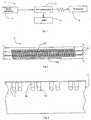
- Fig. 1shows an analysis system 1 for PCR. It has a sample preparation stage 2, a thermal cycling stage 3 for PCR, a waste outlet 4, and a real time detection stage 5 to achieve qPCR.
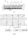
- Fig. 2shows the thermal cycler 3. It has a planar two dimensional serpentine channel 10 which is machined into a block which is segmented into three thermal zones 11, 12, and 13 separated by 1mm air gaps 15. The three thermal zones are controlled to achieve the three individual temperature zones required for the PCR reaction. Each thermal section is controlled by continuous temperature sensing and a PID feedback control system. Circular tubing is laid into a channel in a block of A1 material to ensure biocompatibility for the reaction. The circular tubing gives a smooth internal surface and has no sharp edges to restrict the reaction. This results in stable, spherical sample droplets. The tubing is embedded in the machined channel which results in high heat transfer from the block to the sample.
- Fig. 3shows the machined channel 17 which contains the tubing 10 and a refractive index matching solution.
- the machined channel 17enables the introduction of the refractive index matching solution 16 as it is considerably deeper than the diameter of the tubing 10.
- the solution 16covers the remainder of the channel above the tubing 10 and results in high accuracy detection through the tubing.
- An example of the refractive index matching with the tubingis the use of a glycerine dilution solution.
- the deviceis planar in design, which provides the ability for continuous detection throughout the thermal cycling process. This enables real time quantitative detection (termed "qPCR").
- the assemblymay be sealed using optical quality glass or thin film adhesive.
- Fig 4shows thermal foil heaters 18 for heating the blocks of the thermal zones 11 and 13.
- the low temperature thermal zone 12has a water channel 19 for maintaining a uniform low temperature.
- the thermal sectionsare controlled by temperature sensor monitoring and a PID feedback control system.
- the inlet to the analysis system 1is connected to the PCR preparation system 2.
- sample preparationthe double-stranded DNA sample is combined with two oligonucleotide primers.
- the sampleis segmented into droplets which are wrapped in immiscible oil.
- the oilavoids cross contamination between the sequential droplets and carry-over contamination within the device. This configuration avoids the need to purge the system between different samples.
- a queue of different droplets from the preparation systemmay be passed through the thermal cycler 3 directly.
- the block and tubingare stationary so only the wrapped samples and oil solution move in the thermal cycle system.
- Each thermal zone 11, 12, and 13, including the A1 block and the embedded tubing 10is an isothermal zone. Each zone is controlled to be isothermal with respect to time.
- the velocity of the sample through the deviceis defined by the control of the velocity of the carrier fluid. This is controlled by an external pumping system. The velocity may then be varied to control the residency time of the sample in each temperature zone 11-13.
- the samplepasses to the PCR thermal cycler 3 within the carrier fluid and through an initial denaturation zone 11(a) before commencement of thermal cycling.
- the samplepasses into the high thermal section 11 (a) where it is first separated into single stranded DNA in a process called denaturation at a temperature T H .
- the sampleflows through the device at a steady controlled velocity to the second temperature T L , where the hybridisation process takes place, during which the primers anneal to the complementary sequences of the sample.
- T Lthe second temperature
- T Mthe polymerase process occurs when the primers are extended along the single strand of DNA with a thermostable enzyme.
- the sampleundergoes the same thermal cycling and chemical reaction as it passes through N amplification cycles of the complete thermal device. This results in a maximum two-fold amplification after each cycle and a total amplification of I 1 + E N where I is the initial product, E is the efficiency of the reaction and N is the number of cycles.
- Fluorescent probesare contained in each sample droplet. The fluorescence level is detected in each droplet at each cycle. This quantitative analysis provides information on the specific concentration in the sample.
- the three thermal zonesare controlled to have temperatures as follows:
- the samplethen passes to the PCR thermal cycler 3 within the carrier fluid and through the initial denaturation zone 11(a) before thermal cycling.
- the initial preheatis an extended zone to ensure the sample has denatured successfully before thermal cycling. The requirement for a preheat zone and the length of denaturation time required is dependent on the chemistry being used in the reaction.
- the samplespass into the high temperature zone, of approximately 95°C, where the sample is first separated into single stranded DNA in a process called denaturation.
- the samplethen flows to the low temperature zone 12, of approximately 55°C, where the hybridisation process takes place, during which the primers anneal to the complementary sequences of the sample.
- the polymerase processoccurs when the primers are extended along the single strand of DNA with a thermostable enzyme.
- the sampleundergoes the same thermal cycling and chemical reaction as it passes through each thermal cycle of the serpentine pattern.
- the total number of cycles in the deviceis easily altered by an extension of block length and tubing.
- the system 1has a total cycle number of 30 in this embodiment.
- the devicemay be extended to a longer thermal cycler or a combination of two thermal cyclers to achieve a greater cycle number.
- a cycler 20there are two temperature zones 21 and 23, separated by an insulated air gap 24 to provide the correct temperatures zones necessary for the PCR reaction.
- the zone 21is heated by a thermal foil heater 22, and the zone 23 is heated by natural convection from the top block 21.
- the two zones including the embedded tubingare stationary throughout the reaction and hence isothermal with respect to time.
- the section temperaturesare:
- the position of the lower blockmay be adjusted by increasing the insulation gap 24. This adjusts the temperature of the zone 23.
- the tubingprotrudes below the edge of the bottom aluminium block when it is laid in the channel, providing an inspection window. This is advantageous for the quantitative detection as it provides optical access to the tubing in two planes.
- Different dropletsare queued in the sample preparation device and flow into the thermal cycler in a queue of droplets.
- a suggested optimum configuration for droplet stability, and to avoid contamination,is a droplet diameter of approximately 400 ⁇ m, and a spacing of the same distance.
- the wrapped nature of the dropletsenables continuous flow of alternative droplets without any contamination. This also removes the requirement to purge the system after each reaction.
- the samplethen passes to the PCR thermal cycler within the carrier fluid and through an initial preheat zone before entering the thermal cycling. The preheat zone is necessary for some chemistry for activation and also to ensure the sample is fully denatured before the thermal cycling reaction begins.
- the preheat dwell lengthresults in approximately 10 minutes preheat of the droplets at the higher temperature.
- the samplecontinues into the high temperature zone, of approximately 95°C, where the sample is first separated into single stranded DNA in a process called denaturation.
- the samplethen flows through the device to the low temperature zone, of approximately 60°C, where the hybridisation process takes place, during which the primers anneal to the complementary sequences of the sample.
- the polymerase processoccurs when the primers are extended along the single strand of DNA with a thermostable enzyme.
- the sampleundergoes the same thermal cycling and chemical reaction as it passes through each thermal cycle of the complete device.
- the total number of cycles in the deviceis easily altered by an extension of block length and tubing.
- the systemhas a total cycle number of 50 in this embodiment.
- the devicemay be extended to a longer thermal cycler or a combination of two thermal cyclers to achieve a greater cycle number.
- Real time detectionis applied to the device to provide quantitative polymerase chain reaction (qPCR). This involves the use of fluorescent probes such as SYBR Green or Taqman probes.
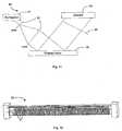
- the devicemay be divided into two sections; one with n cycles and one with p cycles as shown in Fig. 6 .
- the combination of the two devicesenables a PCR total cycle number of n, p or (n+p) depending on the tubing configuration and the heater control.
- Each blockmay be separately controlled to allow for individual use or combined use. Therefore, the cycle number of the device may be varied for greater versatility.
- Fig. 7shows a photograph of segmented droplets flowing though the thermal cycler shown in Fig.2 .
- the systemallows for the quadruplicate amplification of a sample.
- the designavoids cross contamination between successive samples and the planar device allows full field detection during the thermal cycling.
- a suggested optimum configuration for droplet stability, and to avoid contamination,is a droplet diameter of approximately 400 ⁇ m and a spacing of the same distance. This configuration is suggested for the tubing used in this embodiment which has an internal diameter of 400 ⁇ m.
- the wrapped nature of the dropletsenables continuous flow of alternative droplets without any contamination. This also removes the requirement to purge the system.
- Quantitative PCRis a variant of the basic PCR technique.
- the present Q-PCR methodsuse fluorescent probes to monitor the amplification process as it progresses.
- the SYBR Green 1 dyeis commonly used for the fluorescent detection of double-stranded DNA generated during PCR.
- the dyeexhibits a peak excitation maximum at 497 nm and a peak emission maximum at 520 nm.
- Taqman probesmay also be used which are a more target specific probe.
- the Taqman probeshave different excitation and emission wavelengths but one example is the FAM labelled probe which has a peak excitation of 488nm and an emission of 520nm.
- Fig 8demonstrates an example of a fluorescence amplification curve. This was demonstrated using a Taqman probe. There is little change in the fluorescent signal after the first number of thermal cycles. This defines the baseline for the amplification plot. Fluorescence intensity levels above this baseline represent amplification of PCR product. A fluorescent threshold can be fixed above this baseline that defines the threshold cycle, or Ct, for each reaction. The threshold cycle is defined as the fractional cycle number at which the fluorescence passes above a fixed threshold. Ct is observed in the early exponential stages of amplification. The higher the starting DNA template concentration, the sooner a significant increase in fluorescence is observed. Therefore the starting DNA concentration may be determined by the real time fluorescent detection of the amplifying sample.
- the detection system 5comprises:
- the choice of light sourceis dependent on the remainder of the detection system but there are many options including filtered white light, specific wavelength laser or laser diode. Fibre optics may also be incorporated for light transport. The filtering is dependent on the light source and detection system but commercially available filter components may be used.
- a detection indicatorthis will be provided in the sample preparation system.
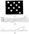
- SYBR green fluorescenceis demonstrated in Fig. 10 . This demonstrates the use of the fluorescence for the amplification detection in the tubing used in the thermal cycler. The increase of fluorescence with increased sample amplification may be seen from the images.
- the detection sensor usedis dependent on the field of view required and the illumination wavelength chosen. Detector options include CCD, CMOS, photodiode and photomultipliers
- the systemamplifies a DNA sample in a polymerase chain reaction comprising the following steps:
- the deviceis planar in design, enabling continuous quantitative PCR and multiple levels for any desired level of parallelism.
- the channel designenables manipulation for refractive index matching within the device for high quality detection. Also, the channel design results in high heat transfer efficiency by embedding the tubing within the channel. As the droplets are wrapped in an immiscible oil, sequential sample contamination or cross-over contamination within the device is avoided.
- Each thermal zoneis controlled by continuous temperature sensing and a PID feedback control system.
- a PID feedback control systemIn the embodiments there are 30 cycles and the particular temperatures defined achieved successful denaturation, annealing and hybridisation reactions.
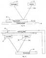
- Fig. 11shows a full field detection system 40 which allows real time detection without any moving parts.
- the system 40comprises an illuminator 41 and lenses 42 illuminating the cycler 20, and a filter 43 for impingement of emission onto a detector 44.
- Thisenables global measurement of the full thermal cycler 20 or the specific measurement at localised points along the thermal cycler. This is demonstrated in a view of the detection system in Fig.12 , in which individual measurements are taken for a linear series of points P.
- the detection measurement point in each cycleis dependent on the fluorescent probes used for qPCR. Some probes fluoresce at any point in the reaction whilst others only fluoresce at the annealing/extension stage.
- Figs. 13 and 14are scanning detection systems for two alternative configurations. These systems also allow real time detection by moving the relative positions of the detection system and the thermal cycler. In the system of Fig. 13 a positioning stage 45 moves the cycler 20, whereas in the system of Fig. 14 a positioning system 46 moves the illuminator 41 and the detector 44.
- the same movementmay be applied to multiple thermal cyclers by simple adding detection and illumination points.
- the angle of illumination and detection, or orientation of the optical fibers,may also be altered to facilitate multiple thermal cycler real time detection.
- Figs. 15 and 16show another quantitative detection configuration, 50.
- Optical fibersare placed at each loop of the tubing in the block.
- a set of fibers 51are placed vertically below the thermal cycler 20 and the fiber ends are perpendicular to the tubing.
- This bundleis attached to a light source 52 which excites the fluorescent particles contained in the droplets as they pass the fiber ends.
- Another bundle of fibers, 53are placed horizontally at the front of the thermal cycler with the fiber ends perpendicular to the tubing.
- This fiber bundle 53collects the emitted light from the fluorescent particles in the droplet as they pass the fiber ends.
- the other end of the fiber bundleis detected by a camera 54 for detection of the droplet fluorescence.
- An example of a detected fiber arrayis shown in Fig. 19 .
- a filter wheel 55may be used for alternative detection of different fluorescent probes. For example, there are probes with excitation wavelengths which are appropriate to use the same excitation source. However, different detection bandwidths will enable the detection of different probes individually. A filter wheel, a spectrometer or an alternative method of wavelength separation will successfully achieve this goal.
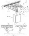
- the throughputmay also be increased by operating a bank 60 of thermal cyclers 61 -64 in parallel.
- a planar systemcan achieve series sampling of w samples and the parallel configuration can contain y parallel levels.
- the continuous multi layered thermal cycler 60results in the product (w x y) sample capability.
- Fig. 18shows a part of a cross-section through the cycler, in the direction of the arrows XIX-XIX of Fig. 17 . This shows the blocks 66 and 67 and the tubing 68. The tubing where it is exposed provides an array of inspection windows 69.
- All detection techniquesmay be applied to a multiple thermal cycler system for quantitative detection.
- the protruding tubing array for a multiple thermal cycler systemas shown in Fig. 17 , can be seen in Fig. 20.
- Fig. 20shows inspection windows 69 for a full 4 x 50 cycle system
- Fig. 21shows a detailed view of a small array of inspection windows 69 more closely.
- the measurement pointsmay be illuminated by full field illumination or point illumination by high speed scanning or fiber optics.
- the detectionmay be carried out the same way, by full field, scanning or simultaneous point detection.
- the inventionimproves upon current well based technology for the quantitative amplification of nucleic acids.
- the reagents and sampleare loaded into a multi-well plate that is then thermally cycled, with each cycle approximately doubling the target number.
- the resulting fluorescent intensityincreases proportionally so that, with calibration, the amplification can be monitored with time.
- Standard techniquesare then available to calculate the number of targets initially present, which is the required output for qPCR.
- the data setis again three dimensional, monitoring over the x, y plane and with time.
- the advantage over the well plateis that when plate amplification is complete the plate must be cleaned or disposed with, and a new plate primed and loaded onto the thermal cycling plate.
- the datais provided continuously for as long as droplets are fed into the thermal cycler. Because there is no carryover the system can be used continuously.
- the geometric arrangement of the capillary tubing in the thermal cyclerallows for serial processing, a procession of droplets, parallel processing and an array of closely packed capillary tubes.
- the rate of production of datais dependant upon the following factors:
- the overall pattern of the flow conduitmay not be serpentine.
- the thermal zonesmay be thermally controlled by flow of hot water rather than directly by heaters in the hotter zones.
- a thermoelectric coolermay be used for one or more cooler zones.
- the flow conduitmay not be in a repeated pattern. Instead, it may be straight or curved, passing through a plurality of sets of thermal zones to provide cycles.
- the detectionmay not involve fluorescence detection. It may alternatively involve detection of other parts of the electromagnetic spectrum such as change of light polarisation, depending on the desired detection technology.
Landscapes
- Chemical & Material Sciences (AREA)
- Health & Medical Sciences (AREA)
- Chemical Kinetics & Catalysis (AREA)
- Life Sciences & Earth Sciences (AREA)
- General Health & Medical Sciences (AREA)
- Analytical Chemistry (AREA)
- Biochemistry (AREA)
- Physics & Mathematics (AREA)
- Immunology (AREA)
- Clinical Laboratory Science (AREA)
- Organic Chemistry (AREA)
- Dispersion Chemistry (AREA)
- Molecular Biology (AREA)
- Zoology (AREA)
- Wood Science & Technology (AREA)
- Proteomics, Peptides & Aminoacids (AREA)
- Hematology (AREA)
- Engineering & Computer Science (AREA)
- Pathology (AREA)
- General Physics & Mathematics (AREA)
- Nuclear Medicine, Radiotherapy & Molecular Imaging (AREA)
- Optics & Photonics (AREA)
- Biophysics (AREA)
- Biotechnology (AREA)
- Microbiology (AREA)
- Bioinformatics & Cheminformatics (AREA)
- General Engineering & Computer Science (AREA)
- Genetics & Genomics (AREA)
- Measuring Or Testing Involving Enzymes Or Micro-Organisms (AREA)
- Apparatus Associated With Microorganisms And Enzymes (AREA)
Description
- The invention relates to analysis of samples to which thermal cycling is applied for nucleic acid amplification, such as in the quantitative polymerase chain reaction (qPCR).
- Conventionally, nucleic acid amplification has involved providing an array of samples in an assay plate and thermally cycling the plate reaction vessel. This, however, involves the laborious task of loading the samples and preparing a fresh assay well plate.
- It is known to provide a thermal cycler for nucleic acid amplification, and
US5270183 ,WO2005/075683 ,US6033880 , andUS6814934 describe thermal cycler analysis systems. - International patent application with publication number
WO 01/07159 - International patent application with publication number
WO 2004/0024330 - The invention is directed towards providing an improved thermal cycler system in which a requirement to heat and cool a reaction vessel is avoided. Another object is to achieve improved detection efficiency.
- According to the invention, there is provided a microfluidic analysis system comprising a thermal cycling device. The device has a plurality of fixed thermal zones and a fixed conduit passing through the thermal zones. The system further comprises a controller for maintaining each thermal zone including its section of conduit at a constant temperature, means for flowing a series of droplets through the conduit so that each droplet is thermally cycled, and a detection system for detecting electromagnetic radiation from droplets at a plurality of cycles of the thermal cycling device. A cycle of the thermal cycling device is a piece of the fixed conduit that a droplet has to pass through to go through a thermal cycle of a serpentine pattern. The flow conduit comprises a channel, a capillary tube inserted into the channel, and a refractive index-matching liquid in the channel. The detection system comprises a plurality of optic fibres for point detection of each of a plurality of cycles of the thermal cycling device. The channel and the capillary tube are configured to receive the refractive index-matching liquid in the channel and at least partly surrounding the capillary tube.
- The invention will be more clearly understood from the following description of some embodiments thereof, given by way of example only with reference to the accompanying drawings in which:-
Fig. 1 is a block diagram of an analysis system of the invention;Fig. 2 is a plan view of a thermal cycler of the system having three thermal zones,Fig. 3 is a vertical cross section, andFig. 4 is an end view of the thermal cycler;Fig. 5 is a perspective view of an alternative thermal cycler, having only two thermal zones;Fig. 6 is a diagram showing an arrangement with two exits, providing a choice of n cycles or n+p cycles;Fig. 7 is a photograph showing droplets flowing in a number of cycles of the thermal cycler having three thermal zones;Fig. 8 is a plot illustrating fluorescence characteristics for detection;Fig. 9 is a block diagram of a detection system of the analysis system;Fig. 10 is a pair of photographs, showing negative and positive fluorescence detection, from left to right;Figs. 11 to 14 are diagrams showing alternative detection arrangements;Figs. 15 and 16 are perspective views showing image capture via optic fibres;Fig. 17 is a perspective view of a three-dimensional cycler for parallel amplification, andFig. 18 is a cross-sectional plan view of this cycler;Fig. 19 is a sample image of part of a detector array captured from the thermal cycler ofFig. 17 ; andFigs. 20 and 21 are views of arrays of windows of the cycler ofFig. 17 .- An analysis system of the invention is based on microfluidics technology. Microfluidic devices themselves have dimensions ranging from several millimetres to micrometers. Typically one of the components or dimensions of the device, such as a channel in the device, is of the order of micrometers.
- The polymerase chain reaction, or PCR, is a powerful technique used to amplify low concentrations of specific DNA sequences to levels which may be detected. PCR can be used to achieve a billionfold increase in target sequence copy number by thermally cycling a specific chemical mix. This makes the PCR method extremely sensitive as it can detect a single DNA molecule in a sample.
Fig. 1 shows ananalysis system 1 for PCR. It has asample preparation stage 2, athermal cycling stage 3 for PCR, awaste outlet 4, and a realtime detection stage 5 to achieve qPCR.Fig. 2 shows thethermal cycler 3. It has a planar twodimensional serpentine channel 10 which is machined into a block which is segmented into threethermal zones 1mm air gaps 15. The three thermal zones are controlled to achieve the three individual temperature zones required for the PCR reaction. Each thermal section is controlled by continuous temperature sensing and a PID feedback control system. Circular tubing is laid into a channel in a block of A1 material to ensure biocompatibility for the reaction. The circular tubing gives a smooth internal surface and has no sharp edges to restrict the reaction. This results in stable, spherical sample droplets. The tubing is embedded in the machined channel which results in high heat transfer from the block to the sample.Fig. 3 shows themachined channel 17 which contains thetubing 10 and a refractive index matching solution. Themachined channel 17 enables the introduction of the refractiveindex matching solution 16 as it is considerably deeper than the diameter of thetubing 10. Thesolution 16 covers the remainder of the channel above thetubing 10 and results in high accuracy detection through the tubing. An example of the refractive index matching with the tubing is the use of a glycerine dilution solution. The device is planar in design, which provides the ability for continuous detection throughout the thermal cycling process. This enables real time quantitative detection (termed "qPCR"). The assembly may be sealed using optical quality glass or thin film adhesive.Fig 4 showsthermal foil heaters 18 for heating the blocks of thethermal zones thermal zone 12 has awater channel 19 for maintaining a uniform low temperature. The thermal sections are controlled by temperature sensor monitoring and a PID feedback control system.- The inlet to the
analysis system 1 is connected to thePCR preparation system 2. During sample preparation the double-stranded DNA sample is combined with two oligonucleotide primers. The sample is segmented into droplets which are wrapped in immiscible oil. The oil avoids cross contamination between the sequential droplets and carry-over contamination within the device. This configuration avoids the need to purge the system between different samples. A queue of different droplets from the preparation system may be passed through thethermal cycler 3 directly. The block and tubing are stationary so only the wrapped samples and oil solution move in the thermal cycle system. Eachthermal zone tubing 10, is an isothermal zone. Each zone is controlled to be isothermal with respect to time. The velocity of the sample through the device is defined by the control of the velocity of the carrier fluid. This is controlled by an external pumping system. The velocity may then be varied to control the residency time of the sample in each temperature zone 11-13. - The sample passes to the PCR
thermal cycler 3 within the carrier fluid and through an initial denaturation zone 11(a) before commencement of thermal cycling. The sample passes into the high thermal section 11 (a) where it is first separated into single stranded DNA in a process called denaturation at a temperature TH. - The sample flows through the device at a steady controlled velocity to the second temperature TL, where the hybridisation process takes place, during which the primers anneal to the complementary sequences of the sample. Finally, as the sample flows through the third and medium temperature zone, TM, the polymerase process occurs when the primers are extended along the single strand of DNA with a thermostable enzyme. The sample undergoes the same thermal cycling and chemical reaction as it passes through N amplification cycles of the complete thermal device. This results in a maximum two-fold amplification after each cycle and a total amplification of

- Fluorescent probes are contained in each sample droplet. The fluorescence level is detected in each droplet at each cycle. This quantitative analysis provides information on the specific concentration in the sample.
- The three thermal zones are controlled to have temperatures as follows:
Zone 11 95°C (TH),Zone 12 55°C (TL),Zone 13 72°C (M).- The prepared sample droplets, wrapped in the carrier fluid, enter the inlet to the thermal cycler at the controlled velocity. The sample then passes to the PCR
thermal cycler 3 within the carrier fluid and through the initial denaturation zone 11(a) before thermal cycling. The initial preheat is an extended zone to ensure the sample has denatured successfully before thermal cycling. The requirement for a preheat zone and the length of denaturation time required is dependent on the chemistry being used in the reaction. The samples pass into the high temperature zone, of approximately 95°C, where the sample is first separated into single stranded DNA in a process called denaturation. The sample then flows to thelow temperature zone 12, of approximately 55°C, where the hybridisation process takes place, during which the primers anneal to the complementary sequences of the sample. Finally, as the sample flows through the thirdmedium temperature zone 13, of approximately 72°C, the polymerase process occurs when the primers are extended along the single strand of DNA with a thermostable enzyme. The sample undergoes the same thermal cycling and chemical reaction as it passes through each thermal cycle of the serpentine pattern. The total number of cycles in the device is easily altered by an extension of block length and tubing. Thesystem 1 has a total cycle number of 30 in this embodiment. The device may be extended to a longer thermal cycler or a combination of two thermal cyclers to achieve a greater cycle number. - Referring to
Fig. 5 , in acycler 20 there are twotemperature zones insulated air gap 24 to provide the correct temperatures zones necessary for the PCR reaction. Thezone 21 is heated by athermal foil heater 22, and thezone 23 is heated by natural convection from thetop block 21. Again, the two zones including the embedded tubing are stationary throughout the reaction and hence isothermal with respect to time. - The section temperatures are:
Zone 21, 95°C (TH),Zone - The position of the lower block may be adjusted by increasing the
insulation gap 24. This adjusts the temperature of thezone 23. The tubing protrudes below the edge of the bottom aluminium block when it is laid in the channel, providing an inspection window. This is advantageous for the quantitative detection as it provides optical access to the tubing in two planes. - The prepared sample droplets, wrapped in the carrier fluid, enter the inlet to the thermal cycler at the controlled velocity. Different droplets are queued in the sample preparation device and flow into the thermal cycler in a queue of droplets. A suggested optimum configuration for droplet stability, and to avoid contamination, is a droplet diameter of approximately 400µm, and a spacing of the same distance. The wrapped nature of the droplets enables continuous flow of alternative droplets without any contamination. This also removes the requirement to purge the system after each reaction. The sample then passes to the PCR thermal cycler within the carrier fluid and through an initial preheat zone before entering the thermal cycling. The preheat zone is necessary for some chemistry for activation and also to ensure the sample is fully denatured before the thermal cycling reaction begins. The preheat dwell length results in approximately 10 minutes preheat of the droplets at the higher temperature. The sample continues into the high temperature zone, of approximately 95°C, where the sample is first separated into single stranded DNA in a process called denaturation. The sample then flows through the device to the low temperature zone, of approximately 60°C, where the hybridisation process takes place, during which the primers anneal to the complementary sequences of the sample. Finally the polymerase process occurs when the primers are extended along the single strand of DNA with a thermostable enzyme. The sample undergoes the same thermal cycling and chemical reaction as it passes through each thermal cycle of the complete device. The total number of cycles in the device is easily altered by an extension of block length and tubing. The system has a total cycle number of 50 in this embodiment. The device may be extended to a longer thermal cycler or a combination of two thermal cyclers to achieve a greater cycle number. Real time detection is applied to the device to provide quantitative polymerase chain reaction (qPCR). This involves the use of fluorescent probes such as SYBR Green or Taqman probes.
- For a larger cycle number, or an optional extension to the cycle number, the device may be divided into two sections; one with n cycles and one with p cycles as shown in
Fig. 6 . The combination of the two devices enables a PCR total cycle number of n, p or (n+p) depending on the tubing configuration and the heater control. Each block may be separately controlled to allow for individual use or combined use. Therefore, the cycle number of the device may be varied for greater versatility. - Case 1:
Block 2 is thermally controlled andblock 1 is uncontrolled (no temperature input). The sample may then enterblock 1, flow through the device and exit the thermal cycler atexit 2 following p cycles. - Case 2: The two blocks are thermally controlled. Then the sample enters
block 1, flows through the device and exits atexit 2 after (n+p) cycles. - Case 3: The tubing is changed to use
exit 1. The sample entersblock 1, flows throughblock 1 and then exits atexit 1 following n cycles. Fig. 7 shows a photograph of segmented droplets flowing though the thermal cycler shown inFig.2 . The system allows for the quadruplicate amplification of a sample. The design avoids cross contamination between successive samples and the planar device allows full field detection during the thermal cycling.- A suggested optimum configuration for droplet stability, and to avoid contamination, is a droplet diameter of approximately 400 µm and a spacing of the same distance. This configuration is suggested for the tubing used in this embodiment which has an internal diameter of 400 µm. The wrapped nature of the droplets enables continuous flow of alternative droplets without any contamination. This also removes the requirement to purge the system.
- Quantitative PCR, or Q-PCR, is a variant of the basic PCR technique. The present Q-PCR methods use fluorescent probes to monitor the amplification process as it progresses. The
SYBR Green 1 dye is commonly used for the fluorescent detection of double-stranded DNA generated during PCR. The dye exhibits a peak excitation maximum at 497 nm and a peak emission maximum at 520 nm. Taqman probes may also be used which are a more target specific probe. The Taqman probes have different excitation and emission wavelengths but one example is the FAM labelled probe which has a peak excitation of 488nm and an emission of 520nm. - Through the analysis of the cycle-to-cycle change in fluorescence signal important information regarding the DNA sample may be obtained. This is done by illuminating the sample and detecting the resulting fluorescence. Different product concentration will demonstrate fluorescence amplification at difference cycle numbers. Through the analysis of the behaviour of the sample the characterisation is possible.
Fig 8 demonstrates an example of a fluorescence amplification curve. This was demonstrated using a Taqman probe. There is little change in the fluorescent signal after the first number of thermal cycles. This defines the baseline for the amplification plot. Fluorescence intensity levels above this baseline represent amplification of PCR product. A fluorescent threshold can be fixed above this baseline that defines the threshold cycle, or Ct, for each reaction. The threshold cycle is defined as the fractional cycle number at which the fluorescence passes above a fixed threshold. Ct is observed in the early exponential stages of amplification. The higher the starting DNA template concentration, the sooner a significant increase in fluorescence is observed. Therefore the starting DNA concentration may be determined by the real time fluorescent detection of the amplifying sample.- Referring to
Fig. 9 thedetection system 5 comprises: - 30,
- light source;
- 31,
- optics for focusing the incident light;
- 32,
- filters for filtering the incident light;
- 34,
- focusing optics for focusing fluorescence emitted by the sample;
- 35,
- filter optics for filtering the emitted fluorescence;
- 36,
- sensor electronics; and
- 37,
- processing electronics.
- The choice of light source is dependent on the remainder of the detection system but there are many options including filtered white light, specific wavelength laser or laser diode. Fibre optics may also be incorporated for light transport. The filtering is dependent on the light source and detection system but commercially available filter components may be used.
- If a detection indicator is used this will be provided in the sample preparation system. The use of SYBR green fluorescence is demonstrated in
Fig. 10 . This demonstrates the use of the fluorescence for the amplification detection in the tubing used in the thermal cycler. The increase of fluorescence with increased sample amplification may be seen from the images. - The detection sensor used is dependent on the field of view required and the illumination wavelength chosen. Detector options include CCD, CMOS, photodiode and photomultipliers
- As the choice and combination of elements chosen are dependent on the overall detection system design and implementation a number of systems are outlined below.
- In summary, the system amplifies a DNA sample in a polymerase chain reaction comprising the following steps:
- a. Introducing spherical droplets of sample contained in an immiscible carrier fluid to the thermal cycler
- b. Passing the sample through circular tubing to provide a smooth internal surface and no sharp edges allowing for most stable, spherical droplets.
- c. Controlling the three thermal zones for successful reaction
- d. Controlling the carrier fluid velocity by an external pumping system to achieve the target residency times in the thermal zones
- e. Passing the sample through the (three) thermally controlled zones to successfully achieve DNA sample amplification.
- f. Repeating step e the necessary number of times to achieve the desired sample amplification
- g. The quantitative detection of the amplification process.
- The device is planar in design, enabling continuous quantitative PCR and multiple levels for any desired level of parallelism.
- The channel design enables manipulation for refractive index matching within the device for high quality detection. Also, the channel design results in high heat transfer efficiency by embedding the tubing within the channel. As the droplets are wrapped in an immiscible oil, sequential sample contamination or cross-over contamination within the device is avoided.
- Each thermal zone is controlled by continuous temperature sensing and a PID feedback control system. In the embodiments there are 30 cycles and the particular temperatures defined achieved successful denaturation, annealing and hybridisation reactions.
Fig. 11 shows a fullfield detection system 40 which allows real time detection without any moving parts. Thesystem 40 comprises anilluminator 41 andlenses 42 illuminating thecycler 20, and afilter 43 for impingement of emission onto adetector 44. This enables global measurement of the fullthermal cycler 20 or the specific measurement at localised points along the thermal cycler. This is demonstrated in a view of the detection system inFig.12 , in which individual measurements are taken for a linear series of points P. The detection measurement point in each cycle is dependent on the fluorescent probes used for qPCR. Some probes fluoresce at any point in the reaction whilst others only fluoresce at the annealing/extension stage.Figs. 13 and 14 are scanning detection systems for two alternative configurations. These systems also allow real time detection by moving the relative positions of the detection system and the thermal cycler. In the system ofFig. 13 apositioning stage 45 moves thecycler 20, whereas in the system ofFig. 14 apositioning system 46 moves theilluminator 41 and thedetector 44.- Whilst the above describes a single thermal cycler, the same movement may be applied to multiple thermal cyclers by simple adding detection and illumination points. The angle of illumination and detection, or orientation of the optical fibers, may also be altered to facilitate multiple thermal cycler real time detection.
Figs. 15 and 16 show another quantitative detection configuration, 50. Optical fibers are placed at each loop of the tubing in the block. A set offibers 51 are placed vertically below thethermal cycler 20 and the fiber ends are perpendicular to the tubing. This bundle is attached to alight source 52 which excites the fluorescent particles contained in the droplets as they pass the fiber ends. Another bundle of fibers, 53, are placed horizontally at the front of the thermal cycler with the fiber ends perpendicular to the tubing. Thisfiber bundle 53 collects the emitted light from the fluorescent particles in the droplet as they pass the fiber ends. The other end of the fiber bundle is detected by acamera 54 for detection of the droplet fluorescence. An example of a detected fiber array is shown inFig. 19 . The continuous acquisition of the fiber bundle image provides the quantitative detection of droplet fluorescence at each individual fiber position. Afilter wheel 55 may be used for alternative detection of different fluorescent probes. For example, there are probes with excitation wavelengths which are appropriate to use the same excitation source. However, different detection bandwidths will enable the detection of different probes individually. A filter wheel, a spectrometer or an alternative method of wavelength separation will successfully achieve this goal.- Referring to
Figs. 17 and 18 , the throughput may also be increased by operating abank 60 of thermal cyclers 61 -64 in parallel. A planar system can achieve series sampling of w samples and the parallel configuration can contain y parallel levels. The continuous multi layeredthermal cycler 60 results in the product (w x y) sample capability. Such a PCR test of the whole genome of any living form, including the human, could be addressed, which would have applications beyond diagnosis, in many fields of pure and applied science.Fig. 18 shows a part of a cross-section through the cycler, in the direction of the arrows XIX-XIX ofFig. 17 . This shows theblocks tubing 68. The tubing where it is exposed provides an array ofinspection windows 69. - All detection techniques may be applied to a multiple thermal cycler system for quantitative detection. The protruding tubing array for a multiple thermal cycler system, as shown in
Fig. 17 , can be seen inFig. 20. Fig. 20 showsinspection windows 69 for a full 4 x 50 cycle system andFig. 21 shows a detailed view of a small array ofinspection windows 69 more closely. The measurement points may be illuminated by full field illumination or point illumination by high speed scanning or fiber optics. The detection may be carried out the same way, by full field, scanning or simultaneous point detection. - The invention improves upon current well based technology for the quantitative amplification of nucleic acids. In that technology the reagents and sample are loaded into a multi-well plate that is then thermally cycled, with each cycle approximately doubling the target number. The resulting fluorescent intensity increases proportionally so that, with calibration, the amplification can be monitored with time. Standard techniques are then available to calculate the number of targets initially present, which is the required output for qPCR.
- In this invention the data set is again three dimensional, monitoring over the x, y plane and with time. The advantage over the well plate is that when plate amplification is complete the plate must be cleaned or disposed with, and a new plate primed and loaded onto the thermal cycling plate. In the invention the data is provided continuously for as long as droplets are fed into the thermal cycler. Because there is no carryover the system can be used continuously.
- The geometric arrangement of the capillary tubing in the thermal cycler allows for serial processing, a procession of droplets, parallel processing and an array of closely packed capillary tubes. The rate of production of data is dependant upon the following factors:
- 1. The droplet length (c. 0.5mm)
- 2. The droplet spacing (c. 1.5mm)
- 3. The droplet velocity (c. 1mm/s)
- 4. The number of parallel lines.
- Typical values are given in brackets. The possible degree of parallelism is very great. Using 0.8mm outside diameter tubing, 100 parallel lines could only take up 80mm of transverse width.
- Using data above, following the time when the first droplets have completed amplification, the system will produce an amplification curve every 0.02 seconds, or 180,000 curves per hour. This is far greater than anything available. Typical high-end systems at present with 384 well plates would need to process 469 plates to achieve the same data set.
- The following are some applications of the invention:
- Rare target detection
- Multiple assay analysis
- Multiple sample/assay analysis
- End point qualitative detection
- The invention is not limited to the embodiments described but may be varied in construction and detail. For example, the overall pattern of the flow conduit may not be serpentine. Alternatively, the thermal zones may be thermally controlled by flow of hot water rather than directly by heaters in the hotter zones. Also, a thermoelectric cooler may be used for one or more cooler zones. Further, the flow conduit may not be in a repeated pattern. Instead, it may be straight or curved, passing through a plurality of sets of thermal zones to provide cycles. Also, the detection may not involve fluorescence detection. It may alternatively involve detection of other parts of the electromagnetic spectrum such as change of light polarisation, depending on the desired detection technology.

Claims (18)
- A microfluidic analysis system (1) comprising a thermal cycling device (3), the device (3) having a plurality of fixed thermal zones (11, 12, 13) and a fixed conduit passing through the thermal zones (11, 12, 13), a controller for maintaining each thermal zone (11, 12, 13) including its section of conduit at a constant temperature, means for flowing a series of droplets through the conduit so that each droplet is thermally cycled, and a detection system (5) for detecting electromagnetic radiation from droplets at a plurality of cycles of the thermal cycling device (3), a cycle of the thermal cycling device (3) being a piece of the fixed conduit that a droplet has to pass through to go through a thermal cycle of a serpentine pattern, wherein the flow conduit comprises a channel (17), a capillary tube inserted into the channel (17), and a refractive index-matching liquid (16) in the channel (17), wherein the detection system (5) comprises a plurality of optic fibres (53) for point detection of each of a plurality of cycles of the thermal cycling device (3), and wherein the channel (17) and the capillary tube are configured to receive the refractive index-matching liquid (16) in the channel (17) and at least partly surrounding the capillary tube.
- A microfluidic analysis system (1) as claimed in claim 1, wherein the conduit is in a single plane.
- A microfluidic analysis system (1) as claimed in claims 1 or 2, wherein the thermal zones (11, 12, 13) are mutually thermally insulated.
- A microfluidic analysis system (1) as claimed in any preceding claim, wherein the capillary tube has a circular cross-section.
- A microfluidic analysis system (1) as claimed in claim 4, wherein the channel (17) has a depth greater them that of the capillary tube.
- A microfluidic analysis system (1) as claimed in any preceding claim, wherein the detection system (5) comprises optics for focusing incident light radiation.
- A microfluidic analysis system (1) as claimed in any preceding claim, wherein the detection system (5) comprises optics for filtering incident radiation.
- A microfluidic analysis system (1) as claimed in any preceding claim, wherein the detection system (5) comprises optics for filtering emitted radiation.
- A microfluidic analysis system (1) as claimed in any of claims 1 to 8 wherein the detection system (5) performs simultaneous detection of emitted light from a plurality of cycles.
- A microfluidic analysis system (1) as claimed in any preceding claim, wherein there is an air gap between adjacent thermal zones (11, 12, 13).
- A microfluidic analysis system (1) as claimed in claim 10, wherein said air gap is adjustable.
- A microfluidic analysis system (1) as claimed in any preceding claim, wherein the flow conduit passes through a hot thermal zone (11, 12, 13) for a length before a first cycle, providing a denaturation zone.
- A microfluidic analysis system (1) as claimed in any preceding claim, wherein the detection system (5) comprises a plurality of optic fibres (51) for point illumination of each of a plurality of cycles.
- A microfluidic analysis system (1) as claimed in 1, wherein the detection system (5) comprises a rotating filter for cyclic filtering of incident or emitted light.
- A microfluidic analysis system (1) as claimed in any preceding claim, wherein the conduit is in a serpentine pattern of multiple folds, each fold extending through a plurality of thermal zones (11, 12, 13).
- A microfluidic analysis system (1) as claimed in any preceding claim, wherein the system comprises a plurality of thermal cycling devices (3) arranged in parallel.
- A microfluidic analysis system (1) as claimed in claim 16, wherein the thermal cycling devices (3) are interconnected to form a physical unit.
- A microfluidic analysis system (1) as claimed in claims 16 or 17 wherein the detection system (5) performs simultaneous detection of emitted light from a plurality of cycles from a plurality of thermal cycling devices (3).
Applications Claiming Priority (2)
| Application Number | Priority Date | Filing Date | Title |
|---|---|---|---|
| US76567006P | 2006-02-07 | 2006-02-07 | |
| PCT/IE2007/000015WO2007091230A1 (en) | 2006-02-07 | 2007-02-07 | A microfluidic analysis system |
Publications (2)
| Publication Number | Publication Date |
|---|---|
| EP1991357A1 EP1991357A1 (en) | 2008-11-19 |
| EP1991357B1true EP1991357B1 (en) | 2016-09-14 |
Family
ID=37946144
Family Applications (1)
| Application Number | Title | Priority Date | Filing Date |
|---|---|---|---|
| EP07705997.0ANot-in-forceEP1991357B1 (en) | 2006-02-07 | 2007-02-07 | A microfluidic analysis system |
Country Status (3)
| Country | Link |
|---|---|
| US (4) | US20080280331A1 (en) |
| EP (1) | EP1991357B1 (en) |
| WO (1) | WO2007091230A1 (en) |
Families Citing this family (62)
| Publication number | Priority date | Publication date | Assignee | Title |
|---|---|---|---|---|
| US8968659B2 (en) | 2003-09-05 | 2015-03-03 | Stokes Bio Limited | Sample dispensing |
| US9597644B2 (en) | 2003-09-05 | 2017-03-21 | Stokes Bio Limited | Methods for culturing and analyzing cells |
| WO2005023427A1 (en) | 2003-09-05 | 2005-03-17 | Stokes Bio Limited | A microfluidic analysis system |
| EP1991357B1 (en) | 2006-02-07 | 2016-09-14 | Stokes Bio Limited | A microfluidic analysis system |
| US8501497B2 (en) | 2006-02-07 | 2013-08-06 | Stokes Bio Limited | Forming sample combinations using liquid bridge systems |
| US20100304446A1 (en)* | 2006-02-07 | 2010-12-02 | Stokes Bio Limited | Devices, systems, and methods for amplifying nucleic acids |
| US8735169B2 (en) | 2006-02-07 | 2014-05-27 | Stokes Bio Limited | Methods for analyzing agricultural and environmental samples |
| EP2298438A1 (en) | 2006-02-07 | 2011-03-23 | Stokes Bio Limited | A microfluidic droplet queuing network |
| US7629124B2 (en)* | 2006-06-30 | 2009-12-08 | Canon U.S. Life Sciences, Inc. | Real-time PCR in micro-channels |
| EP2099935B1 (en)* | 2006-11-30 | 2014-02-26 | The Regents Of The University Of California | Array for detecting microbes |
| EP1962084A1 (en)* | 2007-02-21 | 2008-08-27 | Roche Diagnostics GmbH | Apparatus for emitting and detecting beams of light |
| US8298763B2 (en)* | 2007-03-02 | 2012-10-30 | Lawrence Livermore National Security, Llc | Automated high-throughput flow-through real-time diagnostic system |
| US20110097763A1 (en)* | 2008-05-13 | 2011-04-28 | Advanced Liquid Logic, Inc. | Thermal Cycling Method |
| US9724695B2 (en)* | 2008-06-23 | 2017-08-08 | Canon U.S. Life Sciences, Inc. | Systems and methods for amplifying nucleic acids |
| EP3358019B1 (en) | 2008-08-12 | 2019-09-25 | Stokes Bio Limited | Methods for digital pcr |
| WO2010028288A2 (en) | 2008-09-05 | 2010-03-11 | Aueon, Inc. | Methods for stratifying and annotating cancer drug treatment options |
| US10512910B2 (en) | 2008-09-23 | 2019-12-24 | Bio-Rad Laboratories, Inc. | Droplet-based analysis method |
| US8709762B2 (en) | 2010-03-02 | 2014-04-29 | Bio-Rad Laboratories, Inc. | System for hot-start amplification via a multiple emulsion |
| US8951939B2 (en) | 2011-07-12 | 2015-02-10 | Bio-Rad Laboratories, Inc. | Digital assays with multiplexed detection of two or more targets in the same optical channel |
| US8633015B2 (en) | 2008-09-23 | 2014-01-21 | Bio-Rad Laboratories, Inc. | Flow-based thermocycling system with thermoelectric cooler |
| US9156010B2 (en) | 2008-09-23 | 2015-10-13 | Bio-Rad Laboratories, Inc. | Droplet-based assay system |
| US9764322B2 (en) | 2008-09-23 | 2017-09-19 | Bio-Rad Laboratories, Inc. | System for generating droplets with pressure monitoring |
| US9492797B2 (en) | 2008-09-23 | 2016-11-15 | Bio-Rad Laboratories, Inc. | System for detection of spaced droplets |
| US8663920B2 (en) | 2011-07-29 | 2014-03-04 | Bio-Rad Laboratories, Inc. | Library characterization by digital assay |
| US9417190B2 (en) | 2008-09-23 | 2016-08-16 | Bio-Rad Laboratories, Inc. | Calibrations and controls for droplet-based assays |
| US12090480B2 (en) | 2008-09-23 | 2024-09-17 | Bio-Rad Laboratories, Inc. | Partition-based method of analysis |
| US11130128B2 (en) | 2008-09-23 | 2021-09-28 | Bio-Rad Laboratories, Inc. | Detection method for a target nucleic acid |
| GB2477053B (en)* | 2008-09-23 | 2013-11-13 | Quantalife Inc | Droplet-based assay system |
| US12162008B2 (en) | 2008-09-23 | 2024-12-10 | Bio-Rad Laboratories, Inc. | Partition-based method of analysis |
| US9132394B2 (en) | 2008-09-23 | 2015-09-15 | Bio-Rad Laboratories, Inc. | System for detection of spaced droplets |
| EP2432597A2 (en) | 2009-05-19 | 2012-03-28 | Stokes Bio Limited | Sampling device |
| JP6155418B2 (en) | 2009-09-02 | 2017-07-05 | バイオ−ラッド・ラボラトリーズ・インコーポレーテッド | System for mixing fluids by combining multiple emulsions |
| US8399198B2 (en) | 2010-03-02 | 2013-03-19 | Bio-Rad Laboratories, Inc. | Assays with droplets transformed into capsules |
| EP2550351A4 (en) | 2010-03-25 | 2014-07-09 | Quantalife Inc | Detection system for droplet-based assays |
| EP2556170A4 (en) | 2010-03-25 | 2014-01-01 | Quantalife Inc | Droplet transport system for detection |
| CA2767182C (en) | 2010-03-25 | 2020-03-24 | Bio-Rad Laboratories, Inc. | Droplet generation for droplet-based assays |
| AU2011305445B2 (en) | 2010-09-24 | 2017-03-16 | The Board Of Trustees Of The Leland Stanford Junior University | Direct capture, amplification and sequencing of target DNA using immobilized primers |
| CA3215088A1 (en) | 2010-11-01 | 2012-05-10 | Bio-Rad Laboratories, Inc. | System for forming emulsions |
| US12097495B2 (en) | 2011-02-18 | 2024-09-24 | Bio-Rad Laboratories, Inc. | Methods and compositions for detecting genetic material |
| EP2686449B1 (en) | 2011-03-18 | 2020-11-18 | Bio-Rad Laboratories, Inc. | Multiplexed digital assays with combinatorial use of signals |
| WO2012139125A2 (en) | 2011-04-07 | 2012-10-11 | Life Technologies Corporation | System and methods for making and processing emulsions |
| US9121047B2 (en) | 2011-04-07 | 2015-09-01 | Life Technologies Corporation | System and methods for making and processing emulsions |
| WO2012139038A1 (en)* | 2011-04-08 | 2012-10-11 | Stokes Bio Limited | Systems and methods for continuous flow pcr systems |
| US20140111901A1 (en) | 2011-04-08 | 2014-04-24 | Stokes Bio Limited | System and Method for Charging Fluids |
| US20140127701A1 (en)* | 2011-04-08 | 2014-05-08 | Stokes Bio Limited | End-Point Optical System and Method of Use |
| EP3395957B1 (en) | 2011-04-25 | 2020-08-12 | Bio-Rad Laboratories, Inc. | Methods and compositions for nucleic acid analysis |
| EP2795271B1 (en)* | 2011-12-22 | 2021-07-28 | F. Hoffmann-La Roche AG | Light source lifetime extension in an optical system |
| US9855559B2 (en) | 2011-12-30 | 2018-01-02 | Abbott Molecular Inc. | Microorganism nucleic acid purification from host samples |
| WO2013155531A2 (en) | 2012-04-13 | 2013-10-17 | Bio-Rad Laboratories, Inc. | Sample holder with a well having a wicking promoter |
| US9914957B2 (en) | 2013-02-22 | 2018-03-13 | Bio-Rad Laboratories, Inc. | Devices, systems and methods for thermal control of droplet detection |
| PL2971031T3 (en)* | 2013-03-15 | 2020-04-30 | Drummond Scientific Company | Apparatus for rapidly and cyclically heating and cooling a fluid sample during pcr testing |
| BR112017022133A2 (en)* | 2015-04-13 | 2018-07-03 | Pioneer Hi Bred Int | multiplex streaming droplet platform for high throughput genetic detection |
| CN109072292A (en)* | 2016-02-22 | 2018-12-21 | 拜奥法尔防护有限责任公司 | device and method for fast PCR |
| WO2019103744A1 (en)* | 2017-11-22 | 2019-05-31 | Hewlett-Packard Development Company, L.P. | Temperature-cycling microfluidic devices |
| EP3658841B1 (en)* | 2017-11-22 | 2024-03-27 | Hewlett-Packard Development Company, L.P. | Temperature-controlling microfluidic devices |
| EP3824102A4 (en)* | 2018-11-14 | 2021-07-21 | Hewlett-Packard Development Company, L.P. | Microfluidic devices |
| WO2020109379A1 (en)* | 2018-11-27 | 2020-06-04 | Stilla Technologies | Microfluidic chip architecture with optimized phase flow |
| WO2021119201A1 (en) | 2019-12-10 | 2021-06-17 | Enumerix, Inc. | Methods and systems for three-dimensional lightsheet imaging |
| CN112538428B (en)* | 2020-12-01 | 2023-01-13 | 中国科学院上海微系统与信息技术研究所 | Microfluidic chip based on droplet microfluidic technology and detection method thereof |
| EP4301499A4 (en) | 2021-03-05 | 2025-01-22 | Enumerix, Inc. | Systems and methods for generating droplets and performing digital analyses |
| US12252745B2 (en) | 2021-09-02 | 2025-03-18 | Enumerix, Inc. | Detection and digital quantitation of multiple targets |
| EP4453246A1 (en) | 2021-12-20 | 2024-10-30 | Enumerix, Inc. | Detection and digital quantitation of multiple targets |
Citations (1)
| Publication number | Priority date | Publication date | Assignee | Title |
|---|---|---|---|---|
| WO2004024330A2 (en)* | 2002-09-12 | 2004-03-25 | Quanta Biotech Limited | Thermocycler and sample holder |
Family Cites Families (33)
| Publication number | Priority date | Publication date | Assignee | Title |
|---|---|---|---|---|
| US5270183A (en)* | 1991-02-08 | 1993-12-14 | Beckman Research Institute Of The City Of Hope | Device and method for the automated cycling of solutions between two or more temperatures |
| ATE208658T1 (en)* | 1993-07-28 | 2001-11-15 | Pe Corp Ny | APPARATUS AND METHOD FOR NUCLEIC ACID DUPLICATION |
| US5675155A (en)* | 1995-04-26 | 1997-10-07 | Beckman Instruments, Inc. | Multicapillary fluorescent detection system |
| US5736314A (en)* | 1995-11-16 | 1998-04-07 | Microfab Technologies, Inc. | Inline thermo-cycler |
| US5952202A (en)* | 1998-03-26 | 1999-09-14 | The Perkin Elmer Corporation | Methods using exogenous, internal controls and analogue blocks during nucleic acid amplification |
| WO2001007159A2 (en)* | 1999-07-28 | 2001-02-01 | Genset | Integration of biochemical protocols in a continuous flow microfluidic device |
| AU2001243487A1 (en)* | 2000-03-08 | 2001-09-17 | Imagene Technology, Inc | Lateral flow pcr with amplicon concentration and detection |
| WO2001089696A2 (en)* | 2000-05-24 | 2001-11-29 | Micronics, Inc. | Microfluidic concentration gradient loop |
| US20060127889A1 (en)* | 2000-07-25 | 2006-06-15 | Dotson Stanton B | Method for assessing transgene expression and copy number |
| AU2002307152A1 (en)* | 2001-04-06 | 2002-10-21 | California Institute Of Technology | Nucleic acid amplification utilizing microfluidic devices |
| US6981522B2 (en)* | 2001-06-07 | 2006-01-03 | Nanostream, Inc. | Microfluidic devices with distributing inputs |
| AUPR707101A0 (en)* | 2001-08-16 | 2001-09-06 | Corbett Research Pty Ltd | Continuous flow thermal device |
| US6754414B2 (en)* | 2001-09-27 | 2004-06-22 | Bio-Rad Laboratories, Inc. | Imaging of microarrays using fiber optic exciter |
| CN100439515C (en)* | 2003-03-03 | 2008-12-03 | 清华大学 | A nucleic acid analysis lab-on-a-chip system and its application |
| US7041481B2 (en)* | 2003-03-14 | 2006-05-09 | The Regents Of The University Of California | Chemical amplification based on fluid partitioning |
| GB0315438D0 (en)* | 2003-07-02 | 2003-08-06 | Univ Manchester | Analysis of mixed cell populations |
| WO2005023427A1 (en)* | 2003-09-05 | 2005-03-17 | Stokes Bio Limited | A microfluidic analysis system |
| JP2007528214A (en)* | 2003-12-10 | 2007-10-11 | スミスズ ディテクション インコーポレイティド | Independent monitoring system |
| DE10360406B3 (en) | 2003-12-19 | 2005-03-03 | Ti Automotive (Neuss) Gmbh | Hall effect sensor for vehicle fuel tank level gauge, measures field from moving magnet and is connected by lead to supply or evaluation instrument |
| WO2005075683A1 (en)* | 2004-02-03 | 2005-08-18 | Postech Foundation | High throughput device for performing continuous-flow reactions |
| EP1733023B1 (en)* | 2004-02-24 | 2013-01-23 | Thermal Gradient | Thermal cycling device |
| KR100552706B1 (en)* | 2004-03-12 | 2006-02-20 | 삼성전자주식회사 | Nucleic Acid Amplification Method and Apparatus |
| JP2005295877A (en)* | 2004-04-09 | 2005-10-27 | Taiyo Yuden Co Ltd | Method for analyzing nucleic acid, analyzer and disk for analysis |
| EP1742979A4 (en) | 2004-04-23 | 2008-05-21 | Eugenia Kumacheva | Method of producing polymeric particles with selected size, shape, morphology and composition |
| US20060053384A1 (en)* | 2004-09-07 | 2006-03-09 | La Fetra Frank E Jr | Customizable graphical user interface for utilizing local and network content |
| CN101163800B (en)* | 2005-02-18 | 2013-04-17 | 佳能美国生命科学公司 | Devices and methods for monitoring genomic DNA of organisms |
| US20070141593A1 (en)* | 2005-08-22 | 2007-06-21 | Lee Linda G | Apparatus, system, and method using immiscible-fluid-discrete-volumes |
| EP2298438A1 (en) | 2006-02-07 | 2011-03-23 | Stokes Bio Limited | A microfluidic droplet queuing network |
| US20100304446A1 (en)* | 2006-02-07 | 2010-12-02 | Stokes Bio Limited | Devices, systems, and methods for amplifying nucleic acids |
| EP1991357B1 (en) | 2006-02-07 | 2016-09-14 | Stokes Bio Limited | A microfluidic analysis system |
| US9170060B2 (en)* | 2008-01-22 | 2015-10-27 | Lawrence Livermore National Security, Llc | Rapid microfluidic thermal cycler for nucleic acid amplification |
| US9724695B2 (en)* | 2008-06-23 | 2017-08-08 | Canon U.S. Life Sciences, Inc. | Systems and methods for amplifying nucleic acids |
| US8697011B2 (en)* | 2009-05-19 | 2014-04-15 | Stokes Bio Limited | Sampling device with immiscible fluid supply tube in counter-flow arrangement |
- 2007
- 2007-02-07EPEP07705997.0Apatent/EP1991357B1/ennot_activeNot-in-force
- 2007-02-07USUS12/093,132patent/US20080280331A1/ennot_activeAbandoned
- 2007-02-07WOPCT/IE2007/000015patent/WO2007091230A1/enactiveApplication Filing
- 2014
- 2014-09-15USUS14/486,987patent/US20150140645A1/ennot_activeAbandoned
- 2017
- 2017-02-10USUS15/429,765patent/US11084039B2/enactiveActive
- 2021
- 2021-07-16USUS17/377,575patent/US20220040701A1/ennot_activeAbandoned
Patent Citations (1)
| Publication number | Priority date | Publication date | Assignee | Title |
|---|---|---|---|---|
| WO2004024330A2 (en)* | 2002-09-12 | 2004-03-25 | Quanta Biotech Limited | Thermocycler and sample holder |
Also Published As
| Publication number | Publication date |
|---|---|
| WO2007091230A1 (en) | 2007-08-16 |
| US20150140645A1 (en) | 2015-05-21 |
| US11084039B2 (en) | 2021-08-10 |
| US20170216846A1 (en) | 2017-08-03 |
| US20220040701A1 (en) | 2022-02-10 |
| EP1991357A1 (en) | 2008-11-19 |
| US20080280331A1 (en) | 2008-11-13 |
Similar Documents
| Publication | Publication Date | Title |
|---|---|---|
| US20220040701A1 (en) | Microfluidic analysis system | |
| US9777318B2 (en) | Systems and methods for monitoring the amplification of DNA | |
| EP2972549B1 (en) | Compact optical system for substantially simultaneous monitoring of samples in a sample array | |
| US9724695B2 (en) | Systems and methods for amplifying nucleic acids | |
| US10266873B2 (en) | Optical system for high resolution thermal melt detection | |
| EP2044220B1 (en) | Systems and methods for real-time pcr | |
| CN103249488A (en) | Real-time amplification and microarray detection of nucleic acid targets in flow chip assays | |
| JP2012515558A (en) | Microfluidic flow monitoring | |
| US20170051335A1 (en) | Apparatus and method for thermocyclic biochemical operations | |
| KR102666561B1 (en) | Multi channel isothermal amplification system | |
| KR102648855B1 (en) | Multi channel isothermal amplification system | |
| IE20070073A1 (en) | A microfluidic analysis system | |
| CN111560310B (en) | Random access type digital nucleic acid detection device and use method | |
| IE84897B1 (en) | A microfluidic analysis system | |
| Sayers et al. | A real-time continuous flow polymerase chain reactor for DNA expression quantification | |
| HK1232954A1 (en) | Apparatus and method for thermocyclic biochemical operations |
Legal Events
| Date | Code | Title | Description |
|---|---|---|---|
| PUAI | Public reference made under article 153(3) epc to a published international application that has entered the european phase | Free format text:ORIGINAL CODE: 0009012 | |
| 17P | Request for examination filed | Effective date:20080908 | |
| AK | Designated contracting states | Kind code of ref document:A1 Designated state(s):AT BE BG CH CY CZ DE DK EE ES FI FR GB GR HU IE IS IT LI LT LU LV MC NL PL PT RO SE SI SK TR | |
| 17Q | First examination report despatched | Effective date:20090618 | |
| DAX | Request for extension of the european patent (deleted) | ||
| GRAP | Despatch of communication of intention to grant a patent | Free format text:ORIGINAL CODE: EPIDOSNIGR1 | |
| INTG | Intention to grant announced | Effective date:20160406 | |
| GRAS | Grant fee paid | Free format text:ORIGINAL CODE: EPIDOSNIGR3 | |
| GRAA | (expected) grant | Free format text:ORIGINAL CODE: 0009210 | |
| AK | Designated contracting states | Kind code of ref document:B1 Designated state(s):AT BE BG CH CY CZ DE DK EE ES FI FR GB GR HU IE IS IT LI LT LU LV MC NL PL PT RO SE SI SK TR | |
| REG | Reference to a national code | Ref country code:GB Ref legal event code:FG4D | |
| REG | Reference to a national code | Ref country code:CH Ref legal event code:EP | |
| REG | Reference to a national code | Ref country code:IE Ref legal event code:FG4D | |
| REG | Reference to a national code | Ref country code:AT Ref legal event code:REF Ref document number:828330 Country of ref document:AT Kind code of ref document:T Effective date:20161015 | |
| REG | Reference to a national code | Ref country code:DE Ref legal event code:R096 Ref document number:602007047906 Country of ref document:DE | |
| REG | Reference to a national code | Ref country code:LT Ref legal event code:MG4D | |
| REG | Reference to a national code | Ref country code:NL Ref legal event code:MP Effective date:20160914 | |
| PG25 | Lapsed in a contracting state [announced via postgrant information from national office to epo] | Ref country code:FI Free format text:LAPSE BECAUSE OF FAILURE TO SUBMIT A TRANSLATION OF THE DESCRIPTION OR TO PAY THE FEE WITHIN THE PRESCRIBED TIME-LIMIT Effective date:20160914 Ref country code:LT Free format text:LAPSE BECAUSE OF FAILURE TO SUBMIT A TRANSLATION OF THE DESCRIPTION OR TO PAY THE FEE WITHIN THE PRESCRIBED TIME-LIMIT Effective date:20160914 | |
| REG | Reference to a national code | Ref country code:AT Ref legal event code:MK05 Ref document number:828330 Country of ref document:AT Kind code of ref document:T Effective date:20160914 | |
| PG25 | Lapsed in a contracting state [announced via postgrant information from national office to epo] | Ref country code:ES Free format text:LAPSE BECAUSE OF FAILURE TO SUBMIT A TRANSLATION OF THE DESCRIPTION OR TO PAY THE FEE WITHIN THE PRESCRIBED TIME-LIMIT Effective date:20160914 Ref country code:LV Free format text:LAPSE BECAUSE OF FAILURE TO SUBMIT A TRANSLATION OF THE DESCRIPTION OR TO PAY THE FEE WITHIN THE PRESCRIBED TIME-LIMIT Effective date:20160914 Ref country code:SE Free format text:LAPSE BECAUSE OF FAILURE TO SUBMIT A TRANSLATION OF THE DESCRIPTION OR TO PAY THE FEE WITHIN THE PRESCRIBED TIME-LIMIT Effective date:20160914 Ref country code:NL Free format text:LAPSE BECAUSE OF FAILURE TO SUBMIT A TRANSLATION OF THE DESCRIPTION OR TO PAY THE FEE WITHIN THE PRESCRIBED TIME-LIMIT Effective date:20160914 Ref country code:GR Free format text:LAPSE BECAUSE OF FAILURE TO SUBMIT A TRANSLATION OF THE DESCRIPTION OR TO PAY THE FEE WITHIN THE PRESCRIBED TIME-LIMIT Effective date:20161215 | |
| PG25 | Lapsed in a contracting state [announced via postgrant information from national office to epo] | Ref country code:RO Free format text:LAPSE BECAUSE OF FAILURE TO SUBMIT A TRANSLATION OF THE DESCRIPTION OR TO PAY THE FEE WITHIN THE PRESCRIBED TIME-LIMIT Effective date:20160914 Ref country code:EE Free format text:LAPSE BECAUSE OF FAILURE TO SUBMIT A TRANSLATION OF THE DESCRIPTION OR TO PAY THE FEE WITHIN THE PRESCRIBED TIME-LIMIT Effective date:20160914 | |
| PG25 | Lapsed in a contracting state [announced via postgrant information from national office to epo] | Ref country code:IS Free format text:LAPSE BECAUSE OF FAILURE TO SUBMIT A TRANSLATION OF THE DESCRIPTION OR TO PAY THE FEE WITHIN THE PRESCRIBED TIME-LIMIT Effective date:20170114 Ref country code:BE Free format text:LAPSE BECAUSE OF FAILURE TO SUBMIT A TRANSLATION OF THE DESCRIPTION OR TO PAY THE FEE WITHIN THE PRESCRIBED TIME-LIMIT Effective date:20160914 Ref country code:SK Free format text:LAPSE BECAUSE OF FAILURE TO SUBMIT A TRANSLATION OF THE DESCRIPTION OR TO PAY THE FEE WITHIN THE PRESCRIBED TIME-LIMIT Effective date:20160914 Ref country code:PL Free format text:LAPSE BECAUSE OF FAILURE TO SUBMIT A TRANSLATION OF THE DESCRIPTION OR TO PAY THE FEE WITHIN THE PRESCRIBED TIME-LIMIT Effective date:20160914 Ref country code:PT Free format text:LAPSE BECAUSE OF FAILURE TO SUBMIT A TRANSLATION OF THE DESCRIPTION OR TO PAY THE FEE WITHIN THE PRESCRIBED TIME-LIMIT Effective date:20170116 Ref country code:CZ Free format text:LAPSE BECAUSE OF FAILURE TO SUBMIT A TRANSLATION OF THE DESCRIPTION OR TO PAY THE FEE WITHIN THE PRESCRIBED TIME-LIMIT Effective date:20160914 Ref country code:BG Free format text:LAPSE BECAUSE OF FAILURE TO SUBMIT A TRANSLATION OF THE DESCRIPTION OR TO PAY THE FEE WITHIN THE PRESCRIBED TIME-LIMIT Effective date:20161214 Ref country code:AT Free format text:LAPSE BECAUSE OF FAILURE TO SUBMIT A TRANSLATION OF THE DESCRIPTION OR TO PAY THE FEE WITHIN THE PRESCRIBED TIME-LIMIT Effective date:20160914 | |
| REG | Reference to a national code | Ref country code:DE Ref legal event code:R097 Ref document number:602007047906 Country of ref document:DE | |
| PG25 | Lapsed in a contracting state [announced via postgrant information from national office to epo] | Ref country code:IT Free format text:LAPSE BECAUSE OF FAILURE TO SUBMIT A TRANSLATION OF THE DESCRIPTION OR TO PAY THE FEE WITHIN THE PRESCRIBED TIME-LIMIT Effective date:20160914 | |
| PLBE | No opposition filed within time limit | Free format text:ORIGINAL CODE: 0009261 | |
| STAA | Information on the status of an ep patent application or granted ep patent | Free format text:STATUS: NO OPPOSITION FILED WITHIN TIME LIMIT | |
| PG25 | Lapsed in a contracting state [announced via postgrant information from national office to epo] | Ref country code:DK Free format text:LAPSE BECAUSE OF FAILURE TO SUBMIT A TRANSLATION OF THE DESCRIPTION OR TO PAY THE FEE WITHIN THE PRESCRIBED TIME-LIMIT Effective date:20160914 | |
| 26N | No opposition filed | Effective date:20170615 | |
| PG25 | Lapsed in a contracting state [announced via postgrant information from national office to epo] | Ref country code:MC Free format text:LAPSE BECAUSE OF FAILURE TO SUBMIT A TRANSLATION OF THE DESCRIPTION OR TO PAY THE FEE WITHIN THE PRESCRIBED TIME-LIMIT Effective date:20160914 | |
| REG | Reference to a national code | Ref country code:CH Ref legal event code:PL | |
| PG25 | Lapsed in a contracting state [announced via postgrant information from national office to epo] | Ref country code:CH Free format text:LAPSE BECAUSE OF NON-PAYMENT OF DUE FEES Effective date:20170228 Ref country code:LI Free format text:LAPSE BECAUSE OF NON-PAYMENT OF DUE FEES Effective date:20170228 | |
| REG | Reference to a national code | Ref country code:IE Ref legal event code:MM4A | |
| PG25 | Lapsed in a contracting state [announced via postgrant information from national office to epo] | Ref country code:SI Free format text:LAPSE BECAUSE OF FAILURE TO SUBMIT A TRANSLATION OF THE DESCRIPTION OR TO PAY THE FEE WITHIN THE PRESCRIBED TIME-LIMIT Effective date:20160914 | |
| REG | Reference to a national code | Ref country code:FR Ref legal event code:ST Effective date:20171031 | |
| PG25 | Lapsed in a contracting state [announced via postgrant information from national office to epo] | Ref country code:LU Free format text:LAPSE BECAUSE OF NON-PAYMENT OF DUE FEES Effective date:20170207 | |
| PG25 | Lapsed in a contracting state [announced via postgrant information from national office to epo] | Ref country code:FR Free format text:LAPSE BECAUSE OF NON-PAYMENT OF DUE FEES Effective date:20170228 | |
| PG25 | Lapsed in a contracting state [announced via postgrant information from national office to epo] | Ref country code:IE Free format text:LAPSE BECAUSE OF NON-PAYMENT OF DUE FEES Effective date:20170207 | |
| PG25 | Lapsed in a contracting state [announced via postgrant information from national office to epo] | Ref country code:HU Free format text:LAPSE BECAUSE OF FAILURE TO SUBMIT A TRANSLATION OF THE DESCRIPTION OR TO PAY THE FEE WITHIN THE PRESCRIBED TIME-LIMIT; INVALID AB INITIO Effective date:20070207 | |
| PG25 | Lapsed in a contracting state [announced via postgrant information from national office to epo] | Ref country code:CY Free format text:LAPSE BECAUSE OF NON-PAYMENT OF DUE FEES Effective date:20160914 | |
| PG25 | Lapsed in a contracting state [announced via postgrant information from national office to epo] | Ref country code:TR Free format text:LAPSE BECAUSE OF FAILURE TO SUBMIT A TRANSLATION OF THE DESCRIPTION OR TO PAY THE FEE WITHIN THE PRESCRIBED TIME-LIMIT Effective date:20160914 | |
| PGFP | Annual fee paid to national office [announced via postgrant information from national office to epo] | Ref country code:GB Payment date:20230228 Year of fee payment:17 Ref country code:DE Payment date:20230222 Year of fee payment:17 | |
| REG | Reference to a national code | Ref country code:DE Ref legal event code:R119 Ref document number:602007047906 Country of ref document:DE | |
| GBPC | Gb: european patent ceased through non-payment of renewal fee | Effective date:20240207 | |
| PG25 | Lapsed in a contracting state [announced via postgrant information from national office to epo] | Ref country code:DE Free format text:LAPSE BECAUSE OF NON-PAYMENT OF DUE FEES Effective date:20240903 | |
| PG25 | Lapsed in a contracting state [announced via postgrant information from national office to epo] | Ref country code:GB Free format text:LAPSE BECAUSE OF NON-PAYMENT OF DUE FEES Effective date:20240207 | |
| PG25 | Lapsed in a contracting state [announced via postgrant information from national office to epo] | Ref country code:GB Free format text:LAPSE BECAUSE OF NON-PAYMENT OF DUE FEES Effective date:20240207 Ref country code:DE Free format text:LAPSE BECAUSE OF NON-PAYMENT OF DUE FEES Effective date:20240903 |