EP1991288B1 - Endoscopic suction device - Google Patents
Endoscopic suction deviceDownload PDFInfo
- Publication number
- EP1991288B1 EP1991288B1EP07751819.9AEP07751819AEP1991288B1EP 1991288 B1EP1991288 B1EP 1991288B1EP 07751819 AEP07751819 AEP 07751819AEP 1991288 B1EP1991288 B1EP 1991288B1
- Authority
- EP
- European Patent Office
- Prior art keywords
- port
- biopsy
- valve
- suction
- internal passage
- Prior art date
- Legal status (The legal status is an assumption and is not a legal conclusion. Google has not performed a legal analysis and makes no representation as to the accuracy of the status listed.)
- Active
Links
- 238000001574biopsyMethods0.000claimsdescription78
- 238000000034methodMethods0.000claimsdescription26
- 239000012530fluidSubstances0.000claimsdescription16
- 230000002262irrigationEffects0.000claimsdescription16
- 238000003973irrigationMethods0.000claimsdescription16
- 239000000463materialSubstances0.000claimsdescription11
- 208000007536ThrombosisDiseases0.000description6
- 229920003023plasticPolymers0.000description4
- XLYOFNOQVPJJNP-UHFFFAOYSA-NwaterSubstancesOXLYOFNOQVPJJNP-UHFFFAOYSA-N0.000description4
- FAPWRFPIFSIZLT-UHFFFAOYSA-MSodium chlorideChemical compound[Na+].[Cl-]FAPWRFPIFSIZLT-UHFFFAOYSA-M0.000description3
- 210000003811fingerAnatomy0.000description3
- 238000002347injectionMethods0.000description3
- 239000007924injectionSubstances0.000description3
- 239000011780sodium chlorideSubstances0.000description3
- 230000000881depressing effectEffects0.000description2
- 229920002457flexible plasticPolymers0.000description2
- 210000001035gastrointestinal tractAnatomy0.000description2
- 238000009434installationMethods0.000description2
- 239000002904solventSubstances0.000description2
- 229910001220stainless steelInorganic materials0.000description2
- 239000010935stainless steelSubstances0.000description2
- 230000002411adverseEffects0.000description1
- 230000000994depressogenic effectEffects0.000description1
- 230000001627detrimental effectEffects0.000description1
- 230000000694effectsEffects0.000description1
- 210000003238esophagusAnatomy0.000description1
- 210000003746featherAnatomy0.000description1
- 210000000245forearmAnatomy0.000description1
- 230000003287optical effectEffects0.000description1
- 230000003252repetitive effectEffects0.000description1
- 230000003068static effectEffects0.000description1
- 210000003813thumbAnatomy0.000description1
- 238000002627tracheal intubationMethods0.000description1
- 230000007704transitionEffects0.000description1
- 210000001113umbilicusAnatomy0.000description1
- 210000000707wristAnatomy0.000description1
Images


Classifications
- A—HUMAN NECESSITIES
- A61—MEDICAL OR VETERINARY SCIENCE; HYGIENE
- A61B—DIAGNOSIS; SURGERY; IDENTIFICATION
- A61B1/00—Instruments for performing medical examinations of the interior of cavities or tubes of the body by visual or photographical inspection, e.g. endoscopes; Illuminating arrangements therefor
- A61B1/012—Instruments for performing medical examinations of the interior of cavities or tubes of the body by visual or photographical inspection, e.g. endoscopes; Illuminating arrangements therefor characterised by internal passages or accessories therefor
- A61B1/015—Control of fluid supply or evacuation
- A—HUMAN NECESSITIES
- A61—MEDICAL OR VETERINARY SCIENCE; HYGIENE
- A61B—DIAGNOSIS; SURGERY; IDENTIFICATION
- A61B1/00—Instruments for performing medical examinations of the interior of cavities or tubes of the body by visual or photographical inspection, e.g. endoscopes; Illuminating arrangements therefor
- A61B1/00064—Constructional details of the endoscope body
- A61B1/00066—Proximal part of endoscope body, e.g. handles
- A61B1/00068—Valve switch arrangements
- A—HUMAN NECESSITIES
- A61—MEDICAL OR VETERINARY SCIENCE; HYGIENE
- A61B—DIAGNOSIS; SURGERY; IDENTIFICATION
- A61B1/00—Instruments for performing medical examinations of the interior of cavities or tubes of the body by visual or photographical inspection, e.g. endoscopes; Illuminating arrangements therefor
- A61B1/00131—Accessories for endoscopes
- A61B1/00137—End pieces at either end of the endoscope, e.g. caps, seals or forceps plugs
- A—HUMAN NECESSITIES
- A61—MEDICAL OR VETERINARY SCIENCE; HYGIENE
- A61B—DIAGNOSIS; SURGERY; IDENTIFICATION
- A61B1/00—Instruments for performing medical examinations of the interior of cavities or tubes of the body by visual or photographical inspection, e.g. endoscopes; Illuminating arrangements therefor
- A61B1/012—Instruments for performing medical examinations of the interior of cavities or tubes of the body by visual or photographical inspection, e.g. endoscopes; Illuminating arrangements therefor characterised by internal passages or accessories therefor
- A61B1/018—Instruments for performing medical examinations of the interior of cavities or tubes of the body by visual or photographical inspection, e.g. endoscopes; Illuminating arrangements therefor characterised by internal passages or accessories therefor for receiving instruments
- A—HUMAN NECESSITIES
- A61—MEDICAL OR VETERINARY SCIENCE; HYGIENE
- A61M—DEVICES FOR INTRODUCING MEDIA INTO, OR ONTO, THE BODY; DEVICES FOR TRANSDUCING BODY MEDIA OR FOR TAKING MEDIA FROM THE BODY; DEVICES FOR PRODUCING OR ENDING SLEEP OR STUPOR
- A61M39/00—Tubes, tube connectors, tube couplings, valves, access sites or the like, specially adapted for medical use
- A61M2039/0009—Assemblies therefor designed for particular applications, e.g. contrast or saline injection, suction or irrigation
Definitions
- the present inventionrelates to a suction device for use in removing fluid and material during an endoscopic procedure.
- an endoscopeis inserted through a patient's esophagus and intubated to a work site.
- the endoscopeis flexible and typically has optical and illuminating features that allow the physician to view the work site. Often during such procedures, it becomes necessary for the physician to evacuate blood clots or other materials in the gastrointestinal tract to clear the field of view. These materials are typically removed using components integral to the endoscope.
- An endoscopetypically has two trumpet valves located at the proximal end for the physician to control a suction line and an air/water line.
- an endoscopistwould use the suction line to clear the blood clots.
- the suction line and/or the associated trumpet valvemay clog if heavy or thick fluids are repetitively suctioned during a single procedure. Such clogging may require the procedure time to be extended by interruption of the procedure to clean the suction line, or in certain procedures, may require repeat intubation.
- US 2005/267417discloses an irrigating inlet valve for use with an endoscope.
- the valveis provided with a side entry port which is connected to a tube for providing irrigation fluid to the work site.
- a suction devicefor evacuating blood clots or other materials from an endoscopic work site.
- the suction deviceis designed for installation on the biopsy port of an endoscope.
- the deviceis a direct suction device that does not rely upon the integral trumpet valves or suction line of the endoscope.
- the present inventionis designed for use by an endoscopist to clear blood clots, fluids, small tissue and other material from an internal work site adjacent the distal end of an endoscope.
- the deviceis a direct suction device that is designed for mounting between the biopsy port of an endoscope and a remote suction source.
- the biopsy portalso known in the art as the instrument channel inlet port, provides access to a biopsy inlet valve channel within the endoscope. Instruments may be inserted through this port for use at an internal work site.
- the biopsy portis located on the scope in an external point during a procedure, and distal relative to the endoscope trumpet valves with respect to the physician.
- the suction deviceutilizes the biopsy port channel, does not rely upon the integral trumpet valves and suction line of the endoscope.
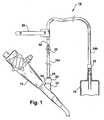
- Figure 1is a side plan view of a suction device 10 made in accordance with an embodiment of the invention.
- the deviceis illustrated installed onto the biopsy port 12 of an exemplary endoscope 14.
- a suction source 16provides a suction to remove and collect materials pulled through the endoscope biopsy port channel and the device 10.
- the deviceincludes biopsy valve connector 20, a flow controller or control valve 22, tubing 24a, 24b and a suction source connector 26.
- the devicealso includes a strap 28 that an operator may use to steady the device against his or her finger, wrist or forearm.
- the strapmay be physically attached to the device and helps maintain the position/orientation of the control valve to make operation easier. This feature also gives the operator a number of options. The operator can loop the strap on the index finger or thumb, maintaining proximate contact with the control valve until actuation is desired. Another option is to attach the device via the strap to the umbilicus of the endoscope so that the position of the turn valve is controlled and more readily accessible.
- the biopsy valve connectoris designed for quick installation on the biopsy port 12.
- the biopsy valve 20may be constructed of flexible material to form an effective connection, such as for example, a press fit connection, on the biopsy port.
- the biopsy valve 20includes a first end, or inlet port 34 and a second end, or outlet port 36.
- An internal passage(not shown in Figure 1 ) is formed between the inlet port 34 and outlet port 36, having a longitudinal axis. Similar coaxial inlet and outlet ports 78, 88 about a longitudinal axis A 1 of an internal passage are shown in Figure 5 .
- a flexible piece of plastic tubing 24aconnects the outlet port 36 and the control valve 22.
- the tubing 24aprovides a fluid connection from the biopsy valve 20 to the control valve 22.
- the line 24ais constructed of flexible plastic tubing and provides a strain-relief/transition to the control valve 22.
- the length of the tubing 24apermits accessibility of the control valve remote from the endoscope.
- the length of tubing 24a between the biopsy valve 20 and the control valve 22may be adequate to allow remote operation from the endoscope, such as for example, 12 inches.
- An additional suction line 24bleads from the downstream side of the control valve 22 to the suction source.
- control valve 22is shown in an open position.
- the control valve 22controls flow of materials through a main body 40.
- the control valvemay be any suitable valve, such as for example, a simple turn valve or check valve.
- the main body 40 illustratedis a tube-shaped hard plastic molded base.
- the control valve 22is less susceptible to clogging compared to an endoscope trumpet valve.
- opposing ends of the main body 50are attached to the flexible tubing 24a, 24b.
- connection structure and techniquescan be used between the main body 50 and the flexible tubing 24a, 24b. Also, any number of sections, combinations, sizes, or lengths of tubing may be used.
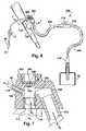
- FIG. 2Another exemplary embodiment of the invention is illustrated in Figure 2 .
- the device 60 shown in Figure 2includes an irrigation system 62 that advantageously does not utilize the air/water line of the endoscope.
- An enlarged perspective view of a portion of the irrigation system 62is best shown in Figure 3 .
- the device 60permits the delivery of fluid to the site during irrigation.
- Two exemplary methods for deliveryinclude attaching either a syringe (typically 60 cc filled with saline) or an external pump (such as an ERBETM brand).
- the delivery ratepressure of the saline exiting the device
- a stand-alone pump that has greater delivery pressurecould be utilized, but this is a relatively expensive option and the pressure would need to be limited or otherwise governed to ensure that no damage occurred to the mucosal wall.
- a hand or electric actuated pump apparatusthat builds air pressure inside the saline reservoir (similar to a plant sprayer or other such device) could also be used. This device could be designed to deliver a maximum pressure that both helped to disrupt and clear the tissue site, without causing any collateral damage.
- the irrigation system 62includes a flexible plastic tube 64 connecting biopsy valve connector 66 and an injection luer 68.
- the tube 64connects to a side entry port 74 in an outer circumferential surface 76 of the biopsy port 66.
- a needlecan be inserted into the distal end 70 of the luer to inject solvents into the biopsy valve channel and subsequently to the internal work site.
- the luermay include a tethered cap.
- the caphas a two-fold purpose. First, it acts to isolate the outside environment from the internal fluids in the device to ensure no leaks occur. Secondly, it prevents air from being drawn through a clamp 72 into the system while the vacuum (suction) is being applied.
- the pinch clamp 72can be used to prevent fluid travel in an opposing direction.
- the pinch clamp designmay allow for one-hand operation. With the pinch clamp closed, fluids that are pulled under suction out of the biopsy port can not travel out of the injection luer 68.
- Figure 4shows a side plan view of an endoscopic suction device 80 that includes an irrigation system 62, as discussed.
- the devicealso includes an alternative flow control valve 82.
- the control valve 82is includes a button 84 pressable inward in a direction D 1 to maintain suction between the biopsy valve 66 and the suction source 16.
- a push-button on/off devicemay be used, such as for example, a trumpet valve.
- a push-button actuated devicethat incorporates a spring to ensure the device is normally in the closed (no suction) position.
- Depressing the buttoncreates an open flow path so that operation is initiated. Releasing downward pressure on the button allows the spring to drive the valve closed. This drastically improves the response time by eliminating delay between the on/off positions.
- partially depressing the buttoncan result in a partially open channel, effectively limiting some of the suction pressure delivered to the site. It is believed that this ability to "feather" the amount of pressure provided can add to the operator's control.
- FIG. 5is an enlarged cross-sectional view of a designated portion of Figure 4 , and shows structural detail of the biopsy valve 66 installed on a biopsy port 12.
- the biopsy valve 66press fits over a standard endoscope stainless steel biopsy port 12.
- the valve 66includes an inlet port 78, an outlet port 88 and a side entry port 74.
- the longitudinal axis A 2 of the side entry portis at an angle ⁇ 1 , as illustrated less than 90 degrees, from the longitudinal axis A 1 of the internal passage 79. This orientation allows injected fluid in the tube 64 to travel downward into the internal passage 79 and toward the biopsy port 12.
- a flexible piece of plastic tubing 24aconnects the outlet port 88 and the control valve 82.
- the device 80Prior to the suction procedure beginning, the device 80 is installed on an exemplary endoscope 90 as shown in Figure 4 .
- the control valve 82 and the pinch clamp 72should be closed. In other words, the button of the trumpet valve 82 should not be depressed.
- the end of the suction line 24bincludes a suction connector 92 that attaches to a dedicated suction source 16. It should be noted that another connector design may be used, such as for example, a T-luer so that a shared suction source could be utilized.
- the control valve 82is actuated to turn the device "ON" (engage suction) to generate suctioning power at the endoscope biopsy channel opening.
- control valve 82By operation of the control valve 82 in this manner, flow of blood clots and other matter travels under suction out of the biopsy port in a direction D 2 and subsequently back through flexible tubing 24a, 24b to the suction source.
- the control valve 82When suction is no longer desired, either during or after the procedure, the control valve 82 is closed to turn the device "OFF" (static mode, no vacuum).
- the device 80is less susceptible to clogging than compared to an endoscope trumpet valve. Further, the device 80 is designed for one-time use and is believed to be economically disposable in intended applications.
- the biopsy valve structuresupports the introduction of devices into the biopsy channel before, during, and after suctioning procedures.
- the biopsy valve being utilized for the endoscopic procedurewould need to be removed from the biopsy port prior to introduction of an instrument. After the instrument is installed and used as required, the instrument is removed prior to the biopsy valve being re-installed for designated device usage. If the instrument was again required, the procedure would be repeated.
- FIG. 6shows a perspective view an endoscopic suction device 100 attached to the biopsy port 112 of an exemplary endoscope 102.
- the deviceincludes a biopsy valve 166, best shown in a cross-sectional view in Figure 7 , a control valve 114, suction tubing 24a, 24b, and a suction connector 116.
- the deviceprovides a suction path between the biopsy port 112 and a direct suction source 16.
- the suction controlis accomplished with a vented port controller 114 as shown in Figure 6 .
- the controllerincludes an open port 116 for finger operation, i.e., the port must be closed for suction to occur through the controller 114. It should be understood by others with ordinary skill in the art that several control valves have been discussed for purpose of example, and the invention can be practiced with any of these examples, or any other valve suitable in the art.
- the biopsy valve 166 shown in Figures 6 and 7can remain installed on the biopsy port and with the two relevant access ports of the biopsy valve essentially intact so that irrigation and endoscopic instruments can be utilized as needed.
- the biopsy valve 166allows the attachment of the suction line 24a to be accomplished from below, allowing the irrigation line 64 to attach to a side entry port, and endoscopic instruments to enter the internal passage through an instrument entry port. Instruments that are inserted into the internal passage advantageously gain access to the instrument channel of the endoscope through the biopsy port.
- FIG. 7an enlarged cross-sectional view of the biopsy valve 166 is shown along the lines 7-7 of Figure 6 .
- the biopsy valve 166press fits over a standard endoscope stainless steel biopsy port 112.
- the valve 166includes an inlet port 178, an outlet port 180, an instrument entry port 200 and a side entry port 174.
- An internal path 179leads from the inlet port 178 to the outlet port 180.
- a flexible piece of plastic tubing 24aconnects the outlet port 180 and the control valve 114.
- the inlet port 178defines an inlet travel path D 3 for suctioned material that is not co-linear with an exit travel path D 4 defined by the outlet port 180.
- the tubing 24adoes not extend directly out of the biopsy port, such as shown in Figures 1 and 4 . It is believed that the exit orientation shown in Figures 6 and 7 is less distractive and more inconspicuous during the medical procedure.
- the longitudinal axis A 3 of the side entry portis less than 90 degrees from the longitudinal axis A 4 of the inlet port 178.
- This orientationallows injected fluid to travel downward into the internal passage 179 and toward the biopsy port 112. It should be noted that the entry angle for the irrigation tubing can be equal to or greater than 90 degrees and still be effective. It has also been determined that the irrigation line could enter at another location (i.e. the tubing 24a) rather than in the valve body.
- the instrument entry port 200is a small aperture in the top of the biopsy valve 166.
- the entry port 200is disposed opposite the inlet port 178 to provide direct axial access to the biopsy port.
- a cap 202When inserting instrument of relatively small diameter, a cap 202 may be left in an installed position as shown. When inserting instruments of larger diameter, the cap may be removed.
- the capis connected to the biopsy valve 166 by a tether 204 for convenience of use. As shown, the cap includes a center aperture 206 therethrough.
- the biopsy valvemay include a flap member 208 internally mounted to the biopsy valve in the internal passage 179. The flap member inhibits fluid movement in a direction from the inlet port 178 of the biopsy valve to the instrument entry port 200.
- cap and flap member disclosedare for exemplary purposes only, and that other structure can be utilized in the practice of the present invention to seal the instrument entry port during suction, including, but not limited to, sufficiently small diameter of the instrument entry port 200 in relation to the outlet port 180 of the biopsy valve 166.
- the operation of the device 100 to perform suctionis similar to the operation of the device 80 shown in Figures 4 and 5 . Certain differences come in activities prior and after suction being performed.
- the device 100is initially installed on the biopsy port 112 and the suction connector 116 is attached to the direct suction source. With the control valve 116, 82, 22 closed, the endoscopist can visually check the internal work site and determine if any suctioning is required. If so, the instrument entry port is closed, for example, by closing the cap 202, and the suction control valve is actuated until adequate suctioning has occurred, and the control valve is closed again.
- the required endoscopic instrumentsuch as for example, a snare, cutting, or injection device, can be inserted through the instrument entry port 200.
- the size of the instrumentwill determine if the instrument is inserted with or without the cap removed. After the endoscopic instrument is removed, either during or after the procedure, the suctioning procedure can be repeated without removal of the biopsy valve 166.
Landscapes
- Health & Medical Sciences (AREA)
- Life Sciences & Earth Sciences (AREA)
- Surgery (AREA)
- Biomedical Technology (AREA)
- Medical Informatics (AREA)
- Optics & Photonics (AREA)
- Pathology (AREA)
- Radiology & Medical Imaging (AREA)
- Biophysics (AREA)
- Engineering & Computer Science (AREA)
- Physics & Mathematics (AREA)
- Heart & Thoracic Surgery (AREA)
- Nuclear Medicine, Radiotherapy & Molecular Imaging (AREA)
- Molecular Biology (AREA)
- Animal Behavior & Ethology (AREA)
- General Health & Medical Sciences (AREA)
- Public Health (AREA)
- Veterinary Medicine (AREA)
- Endoscopes (AREA)
- Instruments For Viewing The Inside Of Hollow Bodies (AREA)
Description
- The present invention relates to a suction device for use in removing fluid and material during an endoscopic procedure.
- Physicians perform endoscopic procedures within the gastrointestinal tract of a patient for a variety of different reasons. In an exemplary operation, an endoscope is inserted through a patient's esophagus and intubated to a work site. The endoscope is flexible and typically has optical and illuminating features that allow the physician to view the work site. Often during such procedures, it becomes necessary for the physician to evacuate blood clots or other materials in the gastrointestinal tract to clear the field of view. These materials are typically removed using components integral to the endoscope.
- An endoscope typically has two trumpet valves located at the proximal end for the physician to control a suction line and an air/water line. Conventionally, an endoscopist would use the suction line to clear the blood clots. However, the suction line and/or the associated trumpet valve may clog if heavy or thick fluids are repetitively suctioned during a single procedure. Such clogging may require the procedure time to be extended by interruption of the procedure to clean the suction line, or in certain procedures, may require repeat intubation.
US 2005/267417 discloses an irrigating inlet valve for use with an endoscope. The valve is provided with a side entry port which is connected to a tube for providing irrigation fluid to the work site.- However, there remains a need in the art for a suction device that resists clogging, allows for repetitive suction of heavy or thick fluids during a single procedure, does not adversely extend procedure time, is easy to operate, and is inexpensive enough to warrant one-time use.
- In several illustrated embodiments of the present invention, a suction device for evacuating blood clots or other materials from an endoscopic work site is disclosed. The suction device is designed for installation on the biopsy port of an endoscope. As such, the device is a direct suction device that does not rely upon the integral trumpet valves or suction line of the endoscope.
- Further features and advantages of the invention will become apparent from the following detailed description made with reference to the accompanying drawings.
Figure 1 is a side plan view of an endoscopic suction device attached between an endoscope biopsy port and a suction system, showing a device including a biopsy valve connector, a flow control valve, and a suction source connector;Figure 2 is a side plan view of another endoscopic suction device, showing a device including an irrigation line;Figure 3 is an enlarged perspective view of a flow control clamp shown on the irrigation line ofFigure 2 ;Figure 4 is a side plan view of yet another endoscopic suction device, showing a device having an alternative flow control valve;Figure 5 is an enlarged cross-sectional view of a designated portion ofFigure 4 , showing structural detail of the biopsy valve connector installed on a biopsy port of an endoscope;Figure 6 is a perspective view of yet another endoscopic suction device, showing a device including an alternative biopsy valve connector and an alterative flow control valve; andFigure 7 is an enlarged cross-sectional view of the biopsy valve connector shown along the lines 7-7 ofFigure 6 , showing structural detail of the biopsy valve connector installed on a biopsy port of an endoscope.- This Detailed Description of the Invention merely describes embodiments of the invention and is not intended to limit the scope of the claims in any way. Indeed, the invention as described is broader than and unlimited by the preferred embodiments, and the terms used have their full ordinary meaning.
- The present invention is designed for use by an endoscopist to clear blood clots, fluids, small tissue and other material from an internal work site adjacent the distal end of an endoscope. The device is a direct suction device that is designed for mounting between the biopsy port of an endoscope and a remote suction source. The biopsy port, also known in the art as the instrument channel inlet port, provides access to a biopsy inlet valve channel within the endoscope. Instruments may be inserted through this port for use at an internal work site. The biopsy port is located on the scope in an external point during a procedure, and distal relative to the endoscope trumpet valves with respect to the physician. The suction device utilizes the biopsy port channel, does not rely upon the integral trumpet valves and suction line of the endoscope.
- Referring now to the drawings,
Figure 1 is a side plan view of asuction device 10 made in accordance with an embodiment of the invention. The device is illustrated installed onto thebiopsy port 12 of anexemplary endoscope 14. Asuction source 16 provides a suction to remove and collect materials pulled through the endoscope biopsy port channel and thedevice 10. - The device includes
biopsy valve connector 20, a flow controller orcontrol valve 22,tubing suction source connector 26. As shown, the device also includes astrap 28 that an operator may use to steady the device against his or her finger, wrist or forearm. The strap may be physically attached to the device and helps maintain the position/orientation of the control valve to make operation easier. This feature also gives the operator a number of options. The operator can loop the strap on the index finger or thumb, maintaining proximate contact with the control valve until actuation is desired. Another option is to attach the device via the strap to the umbilicus of the endoscope so that the position of the turn valve is controlled and more readily accessible. - In an exemplary embodiment, the biopsy valve connector, or
biopsy valve 20, is designed for quick installation on thebiopsy port 12. Thebiopsy valve 20 may be constructed of flexible material to form an effective connection, such as for example, a press fit connection, on the biopsy port. Thebiopsy valve 20 includes a first end, orinlet port 34 and a second end, oroutlet port 36. An internal passage (not shown inFigure 1 ) is formed between theinlet port 34 andoutlet port 36, having a longitudinal axis. Similar coaxial inlet andoutlet ports Figure 5 . - As discussed, a flexible piece of
plastic tubing 24a connects theoutlet port 36 and thecontrol valve 22. Thetubing 24a provides a fluid connection from thebiopsy valve 20 to thecontrol valve 22. Theline 24a is constructed of flexible plastic tubing and provides a strain-relief/transition to thecontrol valve 22. The length of thetubing 24a permits accessibility of the control valve remote from the endoscope. The length oftubing 24a between thebiopsy valve 20 and thecontrol valve 22 may be adequate to allow remote operation from the endoscope, such as for example, 12 inches. Anadditional suction line 24b leads from the downstream side of thecontrol valve 22 to the suction source. - Still referring to
Figure 1 , thecontrol valve 22 is shown in an open position. Thecontrol valve 22 controls flow of materials through amain body 40. The control valve may be any suitable valve, such as for example, a simple turn valve or check valve. Themain body 40 illustrated is a tube-shaped hard plastic molded base. Thecontrol valve 22 is less susceptible to clogging compared to an endoscope trumpet valve. As shown, opposing ends of the main body 50 are attached to theflexible tubing flexible tubing - Another exemplary embodiment of the invention is illustrated in
Figure 2 . Often during evacuation procedures, the addition of water or other solvents are required to dilute materials or loosen blood clots. Conventionally, an endoscopist would use the air/water line of the endoscope to irrigate the work site for a more effective procedure. Thedevice 60 shown inFigure 2 includes anirrigation system 62 that advantageously does not utilize the air/water line of the endoscope. An enlarged perspective view of a portion of theirrigation system 62 is best shown inFigure 3 . Thedevice 60 permits the delivery of fluid to the site during irrigation. Two exemplary methods for delivery include attaching either a syringe (typically 60 cc filled with saline) or an external pump (such as an ERBE™ brand). In either case, the delivery rate (pressure of the saline exiting the device) is minimal. A stand-alone pump that has greater delivery pressure could be utilized, but this is a relatively expensive option and the pressure would need to be limited or otherwise governed to ensure that no damage occurred to the mucosal wall. A hand or electric actuated pump apparatus that builds air pressure inside the saline reservoir (similar to a plant sprayer or other such device) could also be used. This device could be designed to deliver a maximum pressure that both helped to disrupt and clear the tissue site, without causing any collateral damage. - The
irrigation system 62 includes a flexibleplastic tube 64 connectingbiopsy valve connector 66 and aninjection luer 68. Thetube 64 connects to aside entry port 74 in an outercircumferential surface 76 of thebiopsy port 66. A needle can be inserted into thedistal end 70 of the luer to inject solvents into the biopsy valve channel and subsequently to the internal work site. The luer may include a tethered cap. The cap has a two-fold purpose. First, it acts to isolate the outside environment from the internal fluids in the device to ensure no leaks occur. Secondly, it prevents air from being drawn through aclamp 72 into the system while the vacuum (suction) is being applied. The introduction of air would not necessarily be a functionally detrimental issue, but it does result in a whistling sound that can be a distraction/annoyance to the operator. Thepinch clamp 72 can be used to prevent fluid travel in an opposing direction. The pinch clamp design may allow for one-hand operation. With the pinch clamp closed, fluids that are pulled under suction out of the biopsy port can not travel out of theinjection luer 68. Figure 4 shows a side plan view of anendoscopic suction device 80 that includes anirrigation system 62, as discussed. The device also includes an alternativeflow control valve 82. Thecontrol valve 82 is includes abutton 84 pressable inward in a direction D1 to maintain suction between thebiopsy valve 66 and thesuction source 16. Although the design may vary, an exemplary valve has a large lumen to facilitate suction and rotates freely from the open to close positions. To optimize a quick and effortless on/off turning operation, a push-button on/off device may be used, such as for example, a trumpet valve. A push-button actuated device that incorporates a spring to ensure the device is normally in the closed (no suction) position. Depressing the button creates an open flow path so that operation is initiated. Releasing downward pressure on the button allows the spring to drive the valve closed. This drastically improves the response time by eliminating delay between the on/off positions. In addition, partially depressing the button can result in a partially open channel, effectively limiting some of the suction pressure delivered to the site. It is believed that this ability to "feather" the amount of pressure provided can add to the operator's control.Figure 5 is an enlarged cross-sectional view of a designated portion ofFigure 4 , and shows structural detail of thebiopsy valve 66 installed on abiopsy port 12. As discussed, thebiopsy valve 66, press fits over a standard endoscope stainlesssteel biopsy port 12. Thevalve 66 includes aninlet port 78, anoutlet port 88 and aside entry port 74. As shown, the longitudinal axis A2 of the side entry port is at an angle α1, as illustrated less than 90 degrees, from the longitudinal axis A1 of theinternal passage 79. This orientation allows injected fluid in thetube 64 to travel downward into theinternal passage 79 and toward thebiopsy port 12. As discussed, a flexible piece ofplastic tubing 24a connects theoutlet port 88 and thecontrol valve 82.- The operation of the
device 80 will now be discussed. Prior to the suction procedure beginning, thedevice 80 is installed on anexemplary endoscope 90 as shown inFigure 4 . Thecontrol valve 82 and thepinch clamp 72 should be closed. In other words, the button of thetrumpet valve 82 should not be depressed. The end of thesuction line 24b includes asuction connector 92 that attaches to adedicated suction source 16. It should be noted that another connector design may be used, such as for example, a T-luer so that a shared suction source could be utilized. Thecontrol valve 82 is actuated to turn the device "ON" (engage suction) to generate suctioning power at the endoscope biopsy channel opening. By operation of thecontrol valve 82 in this manner, flow of blood clots and other matter travels under suction out of the biopsy port in a direction D2 and subsequently back throughflexible tubing control valve 82 is closed to turn the device "OFF" (static mode, no vacuum). As discussed, thedevice 80 is less susceptible to clogging than compared to an endoscope trumpet valve. Further, thedevice 80 is designed for one-time use and is believed to be economically disposable in intended applications. - When an endoscopist or team of technicians is performing an endoscopic procedure, it is often necessary to alternate uses of the biopsy port. In another exemplary embodiment of the invention, the biopsy valve structure supports the introduction of devices into the biopsy channel before, during, and after suctioning procedures. In certain conventional designs, the biopsy valve being utilized for the endoscopic procedure would need to be removed from the biopsy port prior to introduction of an instrument. After the instrument is installed and used as required, the instrument is removed prior to the biopsy valve being re-installed for designated device usage. If the instrument was again required, the procedure would be repeated.
Figure 6 shows a perspective view anendoscopic suction device 100 attached to thebiopsy port 112 of anexemplary endoscope 102. The device includes abiopsy valve 166, best shown in a cross-sectional view inFigure 7 , acontrol valve 114,suction tubing suction connector 116. The device provides a suction path between thebiopsy port 112 and adirect suction source 16. The suction control is accomplished with a ventedport controller 114 as shown inFigure 6 . The controller includes anopen port 116 for finger operation, i.e., the port must be closed for suction to occur through thecontroller 114. It should be understood by others with ordinary skill in the art that several control valves have been discussed for purpose of example, and the invention can be practiced with any of these examples, or any other valve suitable in the art.- As discussed, the
biopsy valve 166 shown inFigures 6 and 7 can remain installed on the biopsy port and with the two relevant access ports of the biopsy valve essentially intact so that irrigation and endoscopic instruments can be utilized as needed. InFigures 6 and 7 , thebiopsy valve 166 allows the attachment of thesuction line 24a to be accomplished from below, allowing theirrigation line 64 to attach to a side entry port, and endoscopic instruments to enter the internal passage through an instrument entry port. Instruments that are inserted into the internal passage advantageously gain access to the instrument channel of the endoscope through the biopsy port. - Referring to
Figure 7 , an enlarged cross-sectional view of thebiopsy valve 166 is shown along the lines 7-7 ofFigure 6 . As discussed, thebiopsy valve 166, press fits over a standard endoscope stainlesssteel biopsy port 112. Thevalve 166 includes aninlet port 178, anoutlet port 180, aninstrument entry port 200 and aside entry port 174. Aninternal path 179 leads from theinlet port 178 to theoutlet port 180. As discussed, a flexible piece ofplastic tubing 24a connects theoutlet port 180 and thecontrol valve 114. - In this exemplary embodiment, the
inlet port 178 defines an inlet travel path D3 for suctioned material that is not co-linear with an exit travel path D4 defined by theoutlet port 180. As such, thetubing 24a does not extend directly out of the biopsy port, such as shown inFigures 1 and4 . It is believed that the exit orientation shown inFigures 6 and 7 is less distractive and more inconspicuous during the medical procedure. - Referring to the irrigation tubing orientation, the longitudinal axis A3 of the side entry port is less than 90 degrees from the longitudinal axis A4 of the
inlet port 178. This orientation allows injected fluid to travel downward into theinternal passage 179 and toward thebiopsy port 112. It should be noted that the entry angle for the irrigation tubing can be equal to or greater than 90 degrees and still be effective. It has also been determined that the irrigation line could enter at another location (i.e. thetubing 24a) rather than in the valve body. - The
instrument entry port 200 is a small aperture in the top of thebiopsy valve 166. Theentry port 200 is disposed opposite theinlet port 178 to provide direct axial access to the biopsy port. When inserting instrument of relatively small diameter, acap 202 may be left in an installed position as shown. When inserting instruments of larger diameter, the cap may be removed. The cap is connected to thebiopsy valve 166 by atether 204 for convenience of use. As shown, the cap includes acenter aperture 206 therethrough. The biopsy valve may include aflap member 208 internally mounted to the biopsy valve in theinternal passage 179. The flap member inhibits fluid movement in a direction from theinlet port 178 of the biopsy valve to theinstrument entry port 200. It should be understood that the cap and flap member disclosed are for exemplary purposes only, and that other structure can be utilized in the practice of the present invention to seal the instrument entry port during suction, including, but not limited to, sufficiently small diameter of theinstrument entry port 200 in relation to theoutlet port 180 of thebiopsy valve 166. - The operation of the
device 100 to perform suction is similar to the operation of thedevice 80 shown inFigures 4 and 5 . Certain differences come in activities prior and after suction being performed. When an endoscopic procedure is required that will likely involve suctioning during the procedure, thedevice 100 is initially installed on thebiopsy port 112 and thesuction connector 116 is attached to the direct suction source. With thecontrol valve cap 202, and the suction control valve is actuated until adequate suctioning has occurred, and the control valve is closed again. Without removing thebiopsy valve 166, the required endoscopic instrument, such as for example, a snare, cutting, or injection device, can be inserted through theinstrument entry port 200. As discussed, the size of the instrument will determine if the instrument is inserted with or without the cap removed. After the endoscopic instrument is removed, either during or after the procedure, the suctioning procedure can be repeated without removal of thebiopsy valve 166.
Claims (10)
- A device (100) for suctioning material during an endoscopic procedure, the device comprising:a) a biopsy valve (166) having an inlet port (178), an outlet port (180), an instrument entry port (200), and an outer circumferential surface,b) tubing (24a, 24b) connecting said biopsy valve outlet port (180) to a suction source connector (116) disposed remote from said biopsy valve (166); andc) a flow controller (114) fixed to said tubing (24a, 24b) and disposed between said biopsy valve outlet port (180) and said suction source connector (116);d) wherein said biopsy valve (166) defines an internal passage (179) leading from said inlet port (178) to said outlet port (180), said instrument entry port (200) leads to said internal passage (179) and said inlet port (178) is adapted for connection to an endoscope biopsy port (112);further wherein said outer circumferential surface defines a side entry port (174).
- The device (100) of claim 1 wherein said side entry port (174) is configured for injecting irrigation fluid through said biopsy port (112) via said internal passage (179).
- The device (100) of claim 1 wherein said side entry port (174) defines a downward flow path toward said biopsy port (112) angled less than 90 degrees from a longitudinal axis of said inlet port (178).
- The device (100) of claim 2 comprising an irrigation tube (64) having an inlet end and an outlet end, said outlet end secured to said side entry port (174), wherein a fluid may be dispensed through said tube (64) in a direction from said inlet end to said outlet end.
- The device (100) of claim 4 further comprising a controller (72) disposed on said irrigation tubing (64) to selectively prevent flow within said tube (64) in a direction from said biopsy valve (166).
- The device (100) of claim 5 wherein said controller (72) is a hand operated pinch clamp.
- The device (100) of claim 1 comprising a cap (202) removably connectable to said instrument entry port (200) for providing sealable access to said internal passage (179), wherein said cap (202) has a center aperture (206) therethrough for providing access to said internal passage (179).
- The device (100) of claim 1 comprising a flap member (208) internally mounted to said biopsy valve (166) in said internal passage (179), wherein said flap member (208) inhibits fluid movement in a direction from said inlet port (178) of said biopsy valve (166) to said instrument entry port (200).
- The device (100) of claim 1 wherein said outlet port (180) defines a suction exit path that is non-linear with a suction entry path defined by a longitudinal axis of said internal passage (179).
- The device (100) of claim 1 wherein said flow controller (114) is a manually operated vented port having an aperture in an outer circumferential wall, wherein said aperture must be covered to maintain suction between said biopsy valve (180) second end and said suction connector (116).
Applications Claiming Priority (3)
| Application Number | Priority Date | Filing Date | Title |
|---|---|---|---|
| US77624706P | 2006-02-24 | 2006-02-24 | |
| PCT/US2007/005086WO2007103057A2 (en) | 2006-02-24 | 2007-02-26 | Endoscopic suction device |
| US11/678,934US8251945B2 (en) | 2006-02-24 | 2007-02-26 | Endoscopic suction device |
Publications (3)
| Publication Number | Publication Date |
|---|---|
| EP1991288A2 EP1991288A2 (en) | 2008-11-19 |
| EP1991288A4 EP1991288A4 (en) | 2013-09-18 |
| EP1991288B1true EP1991288B1 (en) | 2015-01-21 |
Family
ID=38475363
Family Applications (1)
| Application Number | Title | Priority Date | Filing Date |
|---|---|---|---|
| EP07751819.9AActiveEP1991288B1 (en) | 2006-02-24 | 2007-02-26 | Endoscopic suction device |
Country Status (4)
| Country | Link |
|---|---|
| US (1) | US8251945B2 (en) |
| EP (1) | EP1991288B1 (en) |
| JP (1) | JP2009527337A (en) |
| WO (1) | WO2007103057A2 (en) |
Families Citing this family (30)
| Publication number | Priority date | Publication date | Assignee | Title |
|---|---|---|---|---|
| US7763033B2 (en) | 2006-10-18 | 2010-07-27 | Interlace Medical, Inc. | System and methods for preventing intravasation during intrauterine procedures |
| US9392935B2 (en) | 2006-11-07 | 2016-07-19 | Hologic, Inc. | Methods for performing a medical procedure |
| US8025656B2 (en) | 2006-11-07 | 2011-09-27 | Hologic, Inc. | Methods, systems and devices for performing gynecological procedures |
| WO2008124650A1 (en) | 2007-04-06 | 2008-10-16 | Interlace Medical, Inc. | Method, system and device for tissue removal |
| US9259233B2 (en) | 2007-04-06 | 2016-02-16 | Hologic, Inc. | Method and device for distending a gynecological cavity |
| US8951274B2 (en) | 2007-04-06 | 2015-02-10 | Hologic, Inc. | Methods of high rate, low profile tissue removal |
| US9095366B2 (en) | 2007-04-06 | 2015-08-04 | Hologic, Inc. | Tissue cutter with differential hardness |
| USD612496S1 (en) | 2008-07-15 | 2010-03-23 | Keymed (Medical & Industrial Equipment) Ltd. | Endoscope instrument channel adaptor |
| DE202008010700U1 (en) | 2008-08-12 | 2008-10-23 | Endo-Technik Wolfgang Griesat Gmbh | Connecting and / or connecting body device for attachment to a connection part of a working channel of an endoscope |
| GB2463067B (en)* | 2008-09-01 | 2010-08-04 | Keymed | Adaptor for an endoscope |
| US11903602B2 (en) | 2009-04-29 | 2024-02-20 | Hologic, Inc. | Uterine fibroid tissue removal device |
| WO2010132878A2 (en)* | 2009-05-15 | 2010-11-18 | Us Endoscopy | Manual irrigation pump for intraprocedural irrigation |
| EP2498668A4 (en) | 2009-11-13 | 2013-08-07 | Hologic Inc | Access system with removable outflow channel |
| DE202009017097U1 (en)* | 2009-12-18 | 2011-02-24 | Joimax Gmbh | Endoscope especially for minimally invasive spine surgery |
| US10143357B2 (en)* | 2010-08-10 | 2018-12-04 | Ronald Yamada | Endoscope gripping device |
| KR20120049592A (en)* | 2010-11-09 | 2012-05-17 | 삼성전자주식회사 | Endoscope |
| US8801630B2 (en)* | 2011-09-30 | 2014-08-12 | Olympus Medical Systems Corp. | Method of taking out liquid present inside subject therefrom |
| US9993585B2 (en) | 2011-11-11 | 2018-06-12 | University Of Virginia Patent Foundation | Method suction device and related method thereof |
| US9295454B2 (en)* | 2012-09-21 | 2016-03-29 | Ko-Pen Wang | Double lumen or double wire endobronchial ultrasound-guided histology needle (EBUS) |
| CN102989048A (en)* | 2012-11-27 | 2013-03-27 | 王玉萍 | Blood recovery device |
| US8622896B1 (en)* | 2013-01-04 | 2014-01-07 | Zafer Termanini | Liquid-cooled light source for endoscopy and irrigation/suction and power supply tubing and method thereof |
| USD726903S1 (en)* | 2013-07-22 | 2015-04-14 | Novosanis Nv | Liquid collector |
| CN105407812A (en) | 2013-11-18 | 2016-03-16 | 奥林巴斯株式会社 | Body fluid collection device and endoscope system |
| US9161680B2 (en) | 2013-11-26 | 2015-10-20 | Bracco Diagnostics Inc. | Disposable air/water valve for an endoscopic device |
| JP5953455B1 (en)* | 2014-07-30 | 2016-07-20 | オリンパス株式会社 | Pipe opening / closing device and insertion system including the pipe opening / closing device |
| US20160106400A1 (en)* | 2014-10-15 | 2016-04-21 | New York University | Endoscopic side release biopsy valve |
| CN106793919B (en)* | 2014-12-25 | 2019-06-11 | 奥林巴斯株式会社 | Endoscope |
| US10610092B2 (en)* | 2016-12-19 | 2020-04-07 | Sharon A Hibbs | Endoscope unblocking flush system |
| US20220015614A1 (en)* | 2018-12-11 | 2022-01-20 | University Of Washington | Systems and methods for synchronized suction-injection angioscope |
| WO2025043072A1 (en)* | 2023-08-23 | 2025-02-27 | Boston Scientific Scimed, Inc. | Umbilicus cables for use with medical devices |
Family Cites Families (57)
| Publication number | Priority date | Publication date | Assignee | Title |
|---|---|---|---|---|
| US1937362A (en) | 1930-10-30 | 1933-11-28 | Schellberg Oscar Boto | Colonic apparatus |
| US2701559A (en) | 1951-08-02 | 1955-02-08 | William A Cooper | Apparatus for exfoliating and collecting diagnostic material from inner walls of hollow viscera |
| DE2645048A1 (en) | 1975-10-08 | 1977-04-21 | Gen Electric | PLANTABLE ELECTROCHEMICAL SENSOR |
| US4198958A (en)* | 1977-06-01 | 1980-04-22 | Olympus Optical Co., Ltd. | Flexible cap and instrument seal for a suction control device in an endoscope |
| US4263516A (en)* | 1979-05-10 | 1981-04-21 | Papadakis George M | Breakwater and power generator |
| JPS6015523Y2 (en)* | 1979-10-06 | 1985-05-16 | 株式会社 メドス研究所 | Endoscope suction operation device |
| US5174290A (en) | 1982-03-22 | 1992-12-29 | Mountpelier Investments, S.A. | Tonometric catheter combination |
| US5415165A (en) | 1986-02-27 | 1995-05-16 | Mountpelier Investments | Tonometric catheter combination |
| US4643192A (en) | 1982-03-22 | 1987-02-17 | Regents Of The University Of Michigan | Hollow viscus tonometry |
| US5186172A (en) | 1982-03-22 | 1993-02-16 | Mountpelier Investments, S.A. | Remote sensing tonometric catheter apparatus |
| US6010453A (en) | 1982-03-22 | 2000-01-04 | Instrumentarium Corporation | Tonometric catheter combination |
| USD279925S (en) | 1982-07-15 | 1985-07-30 | Wise Lewis A | Suction tube handle with valve |
| US4736732A (en)* | 1985-09-03 | 1988-04-12 | Olympus Optical Co., Ltd. | Endoscopic fluid changing device |
| CA1264132A (en) | 1987-01-06 | 1990-01-02 | Gloria Ouellette | Colonic irrigator |
| US5053002A (en) | 1988-01-11 | 1991-10-01 | Olympus Corporation | Irrigation system for angioscope |
| US5456251A (en) | 1988-08-26 | 1995-10-10 | Mountpelier Investments, S.A. | Remote sensing tonometric catheter apparatus and method |
| US4944729A (en) | 1988-08-29 | 1990-07-31 | Shiley, Inc. | Femoral arterial cannula |
| US5078688A (en) | 1989-09-22 | 1992-01-07 | Baxter International Inc. | Paracentesis catheter system |
| US5002528A (en) | 1989-12-15 | 1991-03-26 | Aubrey Palestrant | Percutaneous irrigation and drainage system |
| US5312400A (en)* | 1992-10-09 | 1994-05-17 | Symbiosis Corporation | Cautery probes for endoscopic electrosurgical suction-irrigation instrument |
| US5322503A (en)* | 1991-10-18 | 1994-06-21 | Desai Ashvin H | Endoscopic surgical instrument |
| US5395349A (en) | 1991-12-13 | 1995-03-07 | Endovascular Technologies, Inc. | Dual valve reinforced sheath and method |
| US5256150A (en) | 1991-12-13 | 1993-10-26 | Endovascular Technologies, Inc. | Large-diameter expandable sheath and method |
| US5935122A (en) | 1991-12-13 | 1999-08-10 | Endovascular Technologies, Inc. | Dual valve, flexible expandable sheath and method |
| US5333603A (en)* | 1992-02-25 | 1994-08-02 | Daniel Schuman | Endoscope with palm rest |
| US5336174A (en)* | 1992-05-07 | 1994-08-09 | Ivac Corporation | Flow control valve |
| US5269781A (en) | 1992-06-10 | 1993-12-14 | Hewell Iii Todd S | Suction-assisted electrocautery unit |
| US5312327A (en)* | 1992-10-09 | 1994-05-17 | Symbiosis Corporation | Cautery override safety systems endoscopic electrosurgical suction-irrigation instrument |
| US5314406A (en)* | 1992-10-09 | 1994-05-24 | Symbiosis Corporation | Endoscopic electrosurgical suction-irrigation instrument |
| US5336220A (en)* | 1992-10-09 | 1994-08-09 | Symbiosis Corporation | Tubing for endoscopic electrosurgical suction-irrigation instrument |
| US5766211A (en) | 1993-02-08 | 1998-06-16 | Wood; Jan | Medical device for allowing insertion and drainage into a body cavity |
| US5474450A (en) | 1994-02-08 | 1995-12-12 | Chronister; Stephen H. | Dental instrument |
| US5667472A (en)* | 1994-03-18 | 1997-09-16 | Clarus Medical Systems, Inc. | Surgical instrument and method for use with a viewing system |
| US5674193A (en) | 1995-04-05 | 1997-10-07 | Hayes; Lili L. | Oral/nasal-gastric drainage kit |
| US5800493A (en)* | 1995-04-26 | 1998-09-01 | Gynecare, Inc. | Intrauterine ablation system |
| US5725478A (en)* | 1996-03-14 | 1998-03-10 | Saad; Saad A. | Methods and apparatus for providing suction and/or irrigation in a rigid endoscope while maintaining visual contact with a target area through the endoscope |
| US6117070A (en)* | 1996-11-28 | 2000-09-12 | Fuji Photo Optical Co., Ltd. | Plug device for endoscopic instrument channel |
| US5971917A (en)* | 1997-02-26 | 1999-10-26 | Fuji Photo Optical Co., Ltd. | Endoscope having washing ports |
| JPH11267089A (en)* | 1998-03-24 | 1999-10-05 | Olympus Optical Co Ltd | Polyp recovering endoscope system |
| JP3969856B2 (en)* | 1998-08-07 | 2007-09-05 | オリンパス株式会社 | Endoscope |
| US6413228B1 (en) | 1998-12-28 | 2002-07-02 | Pro Duct Health, Inc. | Devices, methods and systems for collecting material from a breast duct |
| JP4293689B2 (en) | 1999-10-05 | 2009-07-08 | 株式会社根本杏林堂 | Contrast medium injection device |
| US6808521B1 (en)* | 1999-11-18 | 2004-10-26 | Kimberly-Clark Worldwide, Inc. | Enteral feeding adapter |
| US6808505B2 (en)* | 2000-02-01 | 2004-10-26 | Kadan Jeffrey S | Diagnostic needle arthroscopy and lavage system |
| US6626827B1 (en) | 2000-09-01 | 2003-09-30 | C. R. Bard, Inc. | Fluid management assembly for use in endoscopic procedures |
| US6699184B2 (en) | 2000-03-10 | 2004-03-02 | C.R. Bard, Inc. | Fluid management assembly having a vented outlet line for use in endoscopic procedures |
| USD468015S1 (en) | 2001-01-22 | 2002-12-31 | Astra Tech Ab | Combined connector with valve and non-return valve for medical equipment |
| US6419662B1 (en) | 2001-01-30 | 2002-07-16 | Anthony Solazzo | Continuous irrigation Y-tubing control valve device and system |
| EP1441777A4 (en)* | 2001-07-17 | 2007-05-30 | Kerberos Proximal Solutions | Fluid exchange system for controlled and localized irrigation and aspiration |
| US7060025B2 (en)* | 2002-03-15 | 2006-06-13 | Ethicon Endo-Surgery, Inc. | Method for controlling position of medical instruments |
| JP2003284675A (en)* | 2002-03-28 | 2003-10-07 | Fuji Photo Optical Co Ltd | Cover type endoscope |
| US7347829B2 (en) | 2002-10-07 | 2008-03-25 | Suros Surgical Systems, Inc. | Introduction system for minimally invasive surgical instruments |
| JP4200731B2 (en)* | 2002-10-23 | 2008-12-24 | フジノン株式会社 | Endoscope forceps plug |
| FR2856912B1 (en)* | 2003-07-04 | 2008-05-23 | Tokendo | REMOVABLE OPERATING DEVICE FOR MEDICALALLY VENTABLE ENDOSCOPIC PROBE |
| US20050113766A1 (en) | 2003-11-26 | 2005-05-26 | Jim Mottola | Primer bulb for contrast media delivery system |
| US20050267417A1 (en)* | 2004-05-25 | 2005-12-01 | Secrest Dean J | Irrigating biopsy inlet valve |
| US20070043262A1 (en)* | 2005-08-18 | 2007-02-22 | Sightline Technologies Ltd. | Fluid supply for endoscope |
- 2007
- 2007-02-26WOPCT/US2007/005086patent/WO2007103057A2/enactiveApplication Filing
- 2007-02-26EPEP07751819.9Apatent/EP1991288B1/enactiveActive
- 2007-02-26JPJP2008556480Apatent/JP2009527337A/enactivePending
- 2007-02-26USUS11/678,934patent/US8251945B2/enactiveActive
Also Published As
| Publication number | Publication date |
|---|---|
| EP1991288A4 (en) | 2013-09-18 |
| EP1991288A2 (en) | 2008-11-19 |
| JP2009527337A (en) | 2009-07-30 |
| US8251945B2 (en) | 2012-08-28 |
| WO2007103057A2 (en) | 2007-09-13 |
| US20070232859A1 (en) | 2007-10-04 |
| WO2007103057A3 (en) | 2008-03-06 |
Similar Documents
| Publication | Publication Date | Title |
|---|---|---|
| EP1991288B1 (en) | Endoscopic suction device | |
| US8915842B2 (en) | Methods and devices for maintaining visibility and providing irrigation and/or suction during surgical procedures | |
| JP3423733B2 (en) | Endoscopic surgical instruments for suction and irrigation | |
| JP5860410B2 (en) | Colon cleaning device | |
| US6464498B2 (en) | Irrigation and aspiration handpiece | |
| US8070756B2 (en) | Polypectomy device and method of use | |
| US6168577B1 (en) | Directed stream blower for clearing a surgical site | |
| US5230704A (en) | Suction/irrigation instrument having reusable handle with disposable fluid path | |
| US5368560A (en) | Suction nozzle | |
| US20050267417A1 (en) | Irrigating biopsy inlet valve | |
| US20070282168A1 (en) | Biopsy inlet valve | |
| WO2004002334A1 (en) | Surgical instrument | |
| BRPI0614120A2 (en) | control system optimized to provide fluid medium to endoscope | |
| US11832795B2 (en) | Fluid control device for endoscope, and endoscope | |
| JPH0374584B2 (en) | ||
| US20070213667A1 (en) | Suction Irrigation Cleaner | |
| CN112336414A (en) | Thrombectomy with venturi aspiration | |
| EP1894585B1 (en) | Adjustable aspiration device | |
| EP0578376A1 (en) | Ultrasonic surgical aspirator | |
| JP2023504457A (en) | Medical devices for drug delivery and related methods of use | |
| US20190216989A1 (en) | Minimally Invasive Suction Sleeve | |
| US7722627B2 (en) | Surgical ligation instrument | |
| CN109528251B (en) | Irrigation and suction device for use with tubular instruments | |
| US12434017B2 (en) | Surgical insufflation systems and methods for use | |
| EP1996250A1 (en) | Apparatus for removal of accumulation of fluid or air below skin level |
Legal Events
| Date | Code | Title | Description |
|---|---|---|---|
| PUAI | Public reference made under article 153(3) epc to a published international application that has entered the european phase | Free format text:ORIGINAL CODE: 0009012 | |
| 17P | Request for examination filed | Effective date:20080924 | |
| AK | Designated contracting states | Kind code of ref document:A2 Designated state(s):DE FR GB | |
| DAX | Request for extension of the european patent (deleted) | ||
| RBV | Designated contracting states (corrected) | Designated state(s):DE FR GB | |
| A4 | Supplementary search report drawn up and despatched | Effective date:20130819 | |
| RIC1 | Information provided on ipc code assigned before grant | Ipc:A61M 1/00 20060101AFI20130812BHEP Ipc:A61B 1/00 20060101ALI20130812BHEP Ipc:A61B 1/015 20060101ALI20130812BHEP Ipc:A61M 39/00 20060101ALI20130812BHEP Ipc:A61B 1/018 20060101ALI20130812BHEP | |
| GRAP | Despatch of communication of intention to grant a patent | Free format text:ORIGINAL CODE: EPIDOSNIGR1 | |
| RIC1 | Information provided on ipc code assigned before grant | Ipc:A61B 1/00 20060101ALI20140730BHEP Ipc:A61M 39/00 20060101ALI20140730BHEP Ipc:A61M 1/00 20060101AFI20140730BHEP Ipc:A61B 1/018 20060101ALI20140730BHEP Ipc:A61B 1/015 20060101ALI20140730BHEP | |
| INTG | Intention to grant announced | Effective date:20140903 | |
| GRAS | Grant fee paid | Free format text:ORIGINAL CODE: EPIDOSNIGR3 | |
| GRAA | (expected) grant | Free format text:ORIGINAL CODE: 0009210 | |
| AK | Designated contracting states | Kind code of ref document:B1 Designated state(s):DE FR GB | |
| REG | Reference to a national code | Ref country code:GB Ref legal event code:FG4D | |
| REG | Reference to a national code | Ref country code:DE Ref legal event code:R096 Ref document number:602007040121 Country of ref document:DE Effective date:20150305 | |
| REG | Reference to a national code | Ref country code:DE Ref legal event code:R097 Ref document number:602007040121 Country of ref document:DE | |
| PLBE | No opposition filed within time limit | Free format text:ORIGINAL CODE: 0009261 | |
| STAA | Information on the status of an ep patent application or granted ep patent | Free format text:STATUS: NO OPPOSITION FILED WITHIN TIME LIMIT | |
| 26N | No opposition filed | Effective date:20151022 | |
| REG | Reference to a national code | Ref country code:FR Ref legal event code:PLFP Year of fee payment:10 | |
| REG | Reference to a national code | Ref country code:FR Ref legal event code:PLFP Year of fee payment:11 | |
| REG | Reference to a national code | Ref country code:FR Ref legal event code:PLFP Year of fee payment:12 | |
| P01 | Opt-out of the competence of the unified patent court (upc) registered | Effective date:20230513 | |
| PGFP | Annual fee paid to national office [announced via postgrant information from national office to epo] | Ref country code:DE Payment date:20250227 Year of fee payment:19 | |
| PGFP | Annual fee paid to national office [announced via postgrant information from national office to epo] | Ref country code:FR Payment date:20250225 Year of fee payment:19 | |
| PGFP | Annual fee paid to national office [announced via postgrant information from national office to epo] | Ref country code:GB Payment date:20250227 Year of fee payment:19 |